
SMC Pneumatics MIW/MIS Escapements · 2011. 5. 12. · Series MIW/MIS ø8, ø12, ø20, ø25, ø32...
18
Series MIW/MIS ø8, ø12, ø20, ø25, ø32 Escapements Series variations Series Stroke (mm) Finger option Stroke adjuster Scraper Bore size (mm) MIW MIS 8 12 20 25 32 8 12 20 25 32 8 10 12 20 25 30 32 50 1415 RSQ RSG RS MI Individual -X D- -X Courtesy of Steven Engineering, Inc.-230 Ryan Way, South San Francisco, CA 94080-6370-Main Office: (650) 588-9200-Outside Local Area: (800) 258-9200-www.stevenengineering.com
Transcript of SMC Pneumatics MIW/MIS Escapements · 2011. 5. 12. · Series MIW/MIS ø8, ø12, ø20, ø25, ø32...

Series MIW/MISø8, ø12, ø20, ø25, ø32
Escapements
����� �� ����� �� ��� ���� �� �� � ���� ������ � ����� ������ ����� ��� ��� ������
Series variations
SeriesStroke (mm) Finger
optionStroke
adjuster ScraperBore size(mm)
MIW
MIS
8122025328
12202532
8 10 12 20 25 30 32 50
1415
RSQ
RSG
RS�
MI�
Individual-X�
D-�
-X�
P1371-P1434-E.qxd 08.11.17 3:43 PM Page 1415
Courtesy of Steven Engineering, Inc.-230 Ryan Way, South San Francisco, CA 94080-6370-Main Office: (650) 588-9200-Outside Local Area: (800) 258-9200-www.stevenengineering.com
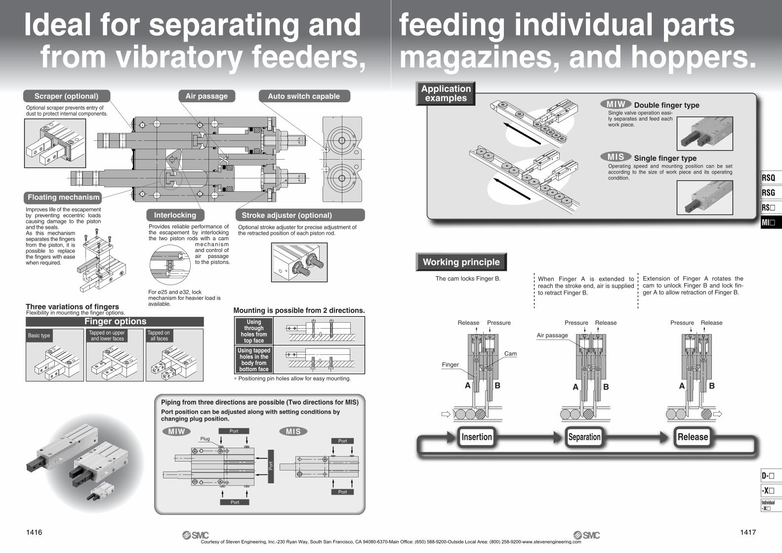
Ideal for separating and from vibratory feeders,
Floating mechanism
Three variations of fingers
Optional scraper prevents entry of dust to protect internal components.
Optional stroke adjuster for precise adjustment of the retracted position of each piston rod.
Scraper (optional) Air passage Auto switch capable
Stroke adjuster (optional)InterlockingProvides reliable performance of the escapement by interlocking the two piston rods with a cam
mechanism and control of air passage to the pistons.
For ø25 and ø32, lock mechanism for heavier load is available.
Flexibility in mounting the finger options.
Finger optionsBasic type Tapped on upper
and lower facesTapped on
all faces
Improves life of the escapement by preventing eccentric loads causing damage to the piston and the seals. As this mechanism separates the fingers from the piston, it is possible to replace the fingers with ease when required.
Mounting is possible from 2 directions.Using
throughholes from
top face
Using tappedholes in thebody from
bottom face
∗ Positioning pin holes allow for easy mounting.
Por
t
Plug
Port
Port
Port
Port
Piping from three directions are possible (Two directions for MIS)Port position can be adjusted along with setting conditions by changing plug position.
MIW MIS
1416
P1371-P1434-E.qxd 08.11.17 3:43 PM Page 1416
feeding individual partsmagazines, and hoppers.
Working principleWorking principle
Applicationexamples
Single finger type
Double finger typeSingle valve operation easi-ly separates and feed each work piece.
MIW
MISOperating speed and mounting position can be set according to the size of work piece and its operating condition.
The cam locks Finger B. When Finger A is extended to reach the stroke end, air is supplied to retract Finger B.
Extension of Finger A rotates the cam to unlock Finger B and lock fin-ger A to allow retraction of Finger B.
Finger
Cam
A B
Air passage
A B A B
Insertion Separation Release
Release ReleasePressure Pressure ReleasePressure
1417
RSQ
RSG
RS�
MI�
Individual-X�
D-�
-X�
P1371-P1434-E.qxd 08.11.17 3:43 PM Page 1417
Courtesy of Steven Engineering, Inc.-230 Ryan Way, South San Francisco, CA 94080-6370-Main Office: (650) 588-9200-Outside Local Area: (800) 258-9200-www.stevenengineering.com

Condition confirmation Confirmation of allowable lateral loadConfirmation of impact by work pieceProcedure 1 Procedure 2 Procedure 3
Model Selection 1Series MIW/MIS
Model Selection
Selection procedure
� The work piece moves horizontally on the conveyor. � When the work piece drops vertically from a shooter, etc.
Operation conditions
Operating pressure P (MPa)
Work piece mass m (Kg)
Work piece quantity x (Qty.)
Point of application L (mm)
Work piece transfer speed
V (m/min)
Coefficient of friction between the work piece and conveyor μ
Operation conditions
Operating pressure P (MPa)
Work piece mass m (Kg)
Work piece quantity x (Qty.)
Point of application L (mm)
Distance of work piece drop
H (mm)
Gravitational acceleration g (m/s2)
Point of application L
Poi
nt o
f ap
plic
atio
n L
Transfer speed V
Procedure 1 Confirmation of conditions
From the graph of operating range, obtain the point of intersection of the total mass of the work piece x ⋅ m (kg) indicated by the axis of ordinates and the transfer speed V (m/min) indicated by the axis of abscissas. Select a model so that the intersection will fall below the point of application L indicated by a line.
1. Calculation of work piece collision speedThe collision speed V is calculated from the distance of work piece fall H.
Work piece collision speed V = 2gH/1000 x 60 (m/min)
2. From the graph of operating range, obtain the intersection of the total mass of the work piece x ⋅ m (kg) indicated by the axis of ordinates and the collision speed V (m/min) obtained by calculation. Select a model so that the intersection will fall below the point of application L indicated by a line.
Procedure 2 Confirmation of impact
1. Calculation of applied lateral load FThe lateral load F equals the coefficient between the work piece and the conveyor. Thus, from the total amount of the work piece and coefficient of friction, F = μ ⋅ x ⋅ m ⋅ g (N)
2. From the graph of allowable lateral load, obtain the allowable lateral load F max from the intersection of the operating pressure and the point of application L indicated by the axis of abscissas. Select a model so that the value will be larger than the lateral load F applied in real operation. Lateral load: F ≤ Allowable lateral load: Fmax
1. Calculation of applied lateral load The lateral load F equals the total load of the work piece. Thus, F = x ⋅ m ⋅ g (N)
Procedure 3 Confirmation of allowable lateral load
1418
P1371-P1434-E.qxd 08.11.17 3:43 PM Page 1418
Courtesy of Steven Engineering, Inc.-230 Ryan Way, South San Francisco, CA 94080-6370-Main Office: (650) 588-9200-Outside Local Area: (800) 258-9200-www.stevenengineering.com
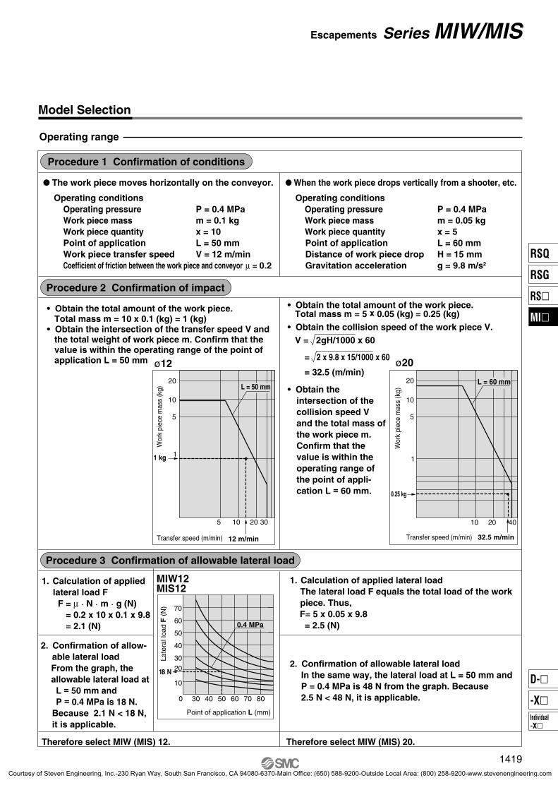
MIW12MIS12
Model Selection
Operating range
� The work piece moves horizontally on the conveyor. � When the work piece drops vertically from a shooter, etc.
Operating conditions Operating pressure P = 0.4 MPa Work piece mass m = 0.1 kg Work piece quantity x = 10 Point of application L = 50 mm Work piece transfer speed V = 12 m/min Coefficient of friction between the work piece and conveyor μ = 0.2
Operating conditions Operating pressure P = 0.4 MPa Work piece mass m = 0.05 kg Work piece quantity x = 5 Point of application L = 60 mm Distance of work piece drop H = 15 mm Gravitation acceleration g = 9.8 m/s2
Procedure 1 Confirmation of conditions
20
10
5
10 20 40
1
0.25 kg
32.5 m/min
L = 60 mm
Wor
k pi
ece
mas
s (k
g)
Transfer speed (m/min)
• Obtain the total amount of the work piece. Total mass m = 10 x 0.1 (kg) = 1 (kg)• Obtain the intersection of the transfer speed V and the total weight of work piece m. Confirm that the value is within the operating range of the point of application L = 50 mm
Therefore select MIW (MIS) 12. Therefore select MIW (MIS) 20.
1. Calculation of applied lateral load F F = μ ⋅ N ⋅ m ⋅ g (N)
= 0.2 x 10 x 0.1 x 9.8= 2.1 (N)
2. Confirmation of allow-able lateral loadFrom the graph, the allowable lateral load at L = 50 mm and P = 0.4 MPa is 18 N. Because 2.1 N < 18 N, it is applicable.
20
10
5
5 10 20 30
11 kg
12 m/min
L = 50 mm
Wor
k pi
ece
mas
s (k
g)
Transfer speed (m/min)
ø12
Procedure 3 Confirmation of allowable lateral load
Procedure 2 Confirmation of impact
• Obtain the intersection of the collision speed V and the total mass of the work piece m. Confirm that the value is within the operating range of the point of appli-cation L = 60 mm.
ø20
• Obtain the total amount of the work piece. Total mass m = 5 x 0.05 (kg) = 0.25 (kg)• Obtain the collision speed of the work piece V. V = 2gH/1000 x 60
= 2 x 9.8 x 15/1000 x 60
= 32.5 (m/min)
1. Calculation of applied lateral load The lateral load F equals the total load of the work piece. Thus,
F= 5 x 0.05 x 9.8 = 2.5 (N)
2. Confirmation of allowable lateral loadIn the same way, the lateral load at L = 50 mm and P = 0.4 MPa is 48 N from the graph. Because 2.5 N < 48 N, it is applicable.
Late
ral l
oad
F (
N)
Point of application L (mm)
807060504030
0.4 MPa
18 N
70
50
60
40
3020
10
0
1419
Escapements Series MIW/MIS
RSQ
RSG
RS�
MI�
Individual-X�
D-�
-X�
P1371-P1434-E.qxd 08.11.17 3:43 PM Page 1419
Courtesy of Steven Engineering, Inc.-230 Ryan Way, South San Francisco, CA 94080-6370-Main Office: (650) 588-9200-Outside Local Area: (800) 258-9200-www.stevenengineering.com
MIW12MIS12
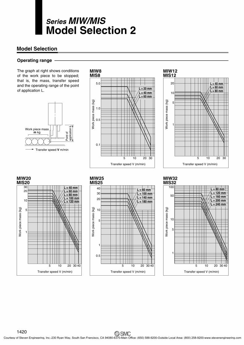
MIW32MIS32
MIW20MIS20
MIW25MIS25
MIW8MIS8
Model Selection 2Series MIW/MIS
Model Selection
Operating range
The graph at right shows conditions of the work piece to be stopped; that is, the mass, transfer speed and the operating range of the point of application L.
Poi
nt o
fap
plic
atio
n L
Work piece massm kg
Transfer speed V m/min
Wor
k pi
ece
mas
s (k
g)Transfer speed V (m/min)
3020105
5
20
1
10L = 80 mmL = 60 mmL = 40 mm
Wor
k pi
ece
mas
s (k
g)
Transfer speed V (m/min)
5 302010
1.0
5.0
0.5
0.1
L = 60 mmL = 40 mmL = 20 mm
Wor
k pi
ece
mas
s (k
g)
Transfer speed V (m/min)
5 40302010
100
50
10
1
5
L = 240 mmL = 200 mmL = 160 mmL = 120 mmL = 80 mm
Wor
k pi
ece
mas
s (k
g)
Transfer speed V (m/min)
5 40302010
10
40
30
20
0.5
5
1
L = 180 mmL = 140 mmL = 100 mmL = 60 mm
Wor
k pi
ece
mas
s (k
g)
Transfer speed V (m/min)
L = 120 mmL = 100 mmL = 80 mmL = 60 mm L = 40 mm
5 40302010
5
3020
10
1
1420
P1371-P1434-E.qxd 08.11.17 3:43 PM Page 1420
Courtesy of Steven Engineering, Inc.-230 Ryan Way, South San Francisco, CA 94080-6370-Main Office: (650) 588-9200-Outside Local Area: (800) 258-9200-www.stevenengineering.com
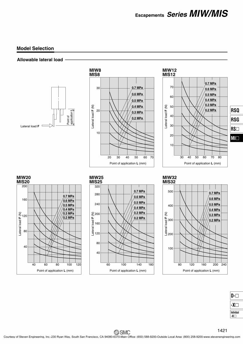
MIW12MIS12
MIW32MIS32
MIW20MIS20
MIW25MIS25
MIW8MIS8
Allowable lateral load
Model Selection
Poi
nt o
fap
plic
atio
n L
Lateral load F
0.2 MPa
0.3 MPa
0.4 MPa
0.5 MPa
0.6 MPa
0.7 MPa
Point of application L (mm)
30 60 70504020
Late
ral l
oad
F (
N)
20
30
10
0.2 MPa
0.3 MPa
0.4 MPa
0.5 MPa
0.6 MPa
0.7 MPa
Late
ral l
oad
F (
N)
Point of application L (mm)
807030 40 50 60
50
70
40
30
20
10
60
Late
ral l
oad
F (
N)
Point of application L (mm)
24020016012080
500
400
100
300
200
0.2 MPa
0.3 MPa
0.4 MPa
0.5 MPa
0.6 MPa
0.7 MPa
Late
ral l
oad
F (
N)
Point of application L (mm)
18014010060
160
320
280
240
200
40
120
80
0.2 MPa
0.3 MPa
0.4 MPa
0.5 MPa
0.6 MPa
0.7 MPa
Late
ral l
oad
F (
N)
Point of application L (mm)
40 1201008060
120
200
160
80
40
0.2 MPa0.3 MPa0.4 MPa 0.5 MPa 0.6 MPa0.7 MPa
1421
Escapements Series MIW/MIS
RSQ
RSG
RS�
MI�
Individual-X�
D-�
-X�
P1371-P1434-E.qxd 08.11.17 3:43 PM Page 1421
Courtesy of Steven Engineering, Inc.-230 Ryan Way, South San Francisco, CA 94080-6370-Main Office: (650) 588-9200-Outside Local Area: (800) 258-9200-www.stevenengineering.com

1422
12 1 A SD
50 1 A SD M9BW
M9BW
Port thread type
MIS
12
32
MIW
Cylinder bore8
12202532
8 mm12 mm20 mm25 mm32 mm
M9NVM9PVM9BV
M9NWVM9PWVM9BWV
M9NM9PM9B
M9NWM9PWM9BW
�
How to Order
Finger options
Nil: Basic type(Standard type)
1: Tapped on upper and lower faces
2: Tapped on all faces(5 surfaces including end surface)
Single finger type
Double finger type
ø8, ø12ø20, ø25Nil
TNTF
RcNPT
G
M thread
TypeSymbol Bore size
ø32
Stroke∗ Refer to the next page for standard stroke table.
Finger options
Nil: Basic type(Standard type)
1: Tapped on upper and lower faces
2: Tapped on all faces(5 surfaces including end surface)
Type of auto switchWithout auto switch (built-in magnet)Nil
∗ Refer to the table below for auto switch part numbers.
2 pcs.1 pc.
Number of auto switchesNilS
Made to OrderFor detailes, refer to page 1423.
Type Special functionElectrical
entry
Load voltageWiring
(output)Pre-wiredconnector
Applicable loadDC AC
Auto switch models Lead wire length (m)
Perpendicular In-line0.5(Nil)
3(L)
5(Z)
������
������
������
������
������
1(M)Ind
icator
light
Applicable auto switches/Refer to pages 1719 to 1827 for detailed specifications of auto switches.
Solid
sta
te s
witc
h
∗ Lead wire length symbols: 0.5 m ········ Nil (Example) M9NW 1 m ········ M (Example) M9NWM 3 m ········ L (Example) M9NWL 5 m ········ Z (Example) M9NWZ
∗ Refer to pages 1784 and 1785 for the details of auto switches with a pre-wired connector. ∗ Auto switches are shipped together (not assembled).
∗ Solid state auto switches marked with “�” are produced upon receipt of order.
24 V
3-wire (NPN)3-wire (PNP)
2-wire3-wire (NPN)3-wire (PNP)
2-wire
YesGrommet
ICcircuit
ICcircuit
�
�
Relay, PLC
�
Diagnostic indication(2-color display)
5 V, 12 V
12 V
5 V, 12 V
12 V
Strokeadjuster
Scraper
NoYes
NilA
NoYes
NilS
Series MIW/MISEscapements
ø8, ø12, ø20, ø25, ø32
3-2-64-MIW-MIS.qxd 09.9.30 4:15 PM Page 1
Courtesy of Steven Engineering, Inc.-230 Ryan Way, South San Francisco, CA 94080-6370-Main Office: (650) 588-9200-Outside Local Area: (800) 258-9200-www.stevenengineering.com
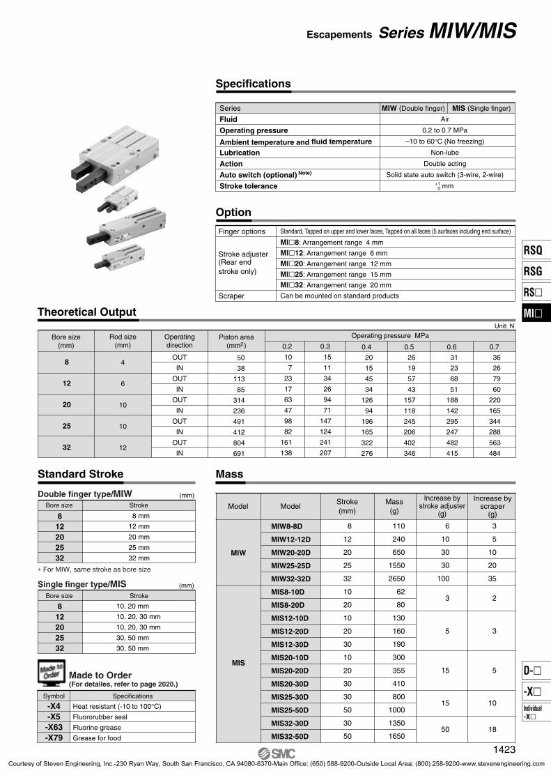
Theoretical Output
0.4 0.5 0.6 0.7
20
15
45
34
126
94
196
165
322
276
26
19
57
43
157
118
245
206
402
346
31
23
68
51
188
142
295
247
482
415
36
26
79
60
220
165
344
288
563
484
0.3
15
11
34
26
94
71
147
124
241
207
0.2
10
7
23
17
63
47
98
82
161
138
50
38
113
85
314
236
491
412
804
691
OUT
IN
OUT
IN
OUT
IN
OUT
IN
OUT
IN
4
6
10
10
12
8
12
20
25
32
8
12
20
25
32
10
20
10
20
30
10
20
30
30
50
30
50
110
240
650
1550
2650
62
80
130
160
190
300
355
410
800
1000
1350
1650
6
10
30
30
100
3
5
15
15
50
3
5
10
20
35
2
3
5
10
18
MIW8-8D
MIW12-12D
MIW20-20D
MIW25-25D
MIW32-32D
MIS8-10D
MIS8-20D
MIS12-10D
MIS12-20D
MIS12-30D
MIS20-10D
MIS20-20D
MIS20-30D
MIS25-30D
MIS25-50D
MIS32-30D
MIS32-50D
MIW
MIS
Double finger type/MIW
812202532
8 mm
12 mm
20 mm
25 mm
32 mm
Bore size Stroke
(mm)
∗ For MIW, same stroke as bore size
Single finger type/MIS
812202532
10, 20 mm
10, 20, 30 mm
10, 20, 30 mm
30, 50 mm
30, 50 mm
Bore size Stroke
(mm)
Symbol Specifications
Heat resistant (-10 to 100°C)
Fluororubber seal
Fluorine grease
Grease for food
-X4-X5-X63-X79
Made to Order(For detailes, refer to page 2020.)
Specifications
Option
Finger options
MI�8: Arrangement range 4 mm
MI�12: Arrangement range 6 mm
MI�20: Arrangement range 12 mm
MI�25: Arrangement range 15 mm
MI�32: Arrangement range 20 mm
Can be mounted on standard products
Standard, Tapped on upper and lower faces, Tapped on all faces (5 surfaces including end surface)
Stroke adjuster(Rear end stroke only)
Scraper
Series
Fluid
Operating pressure
Ambient temperature and fluid temperature
Lubrication
Action
Auto switch (optional) Note)
Stroke tolerance
Air
0.2 to 0.7 MPa
–10 to 60°C (No freezing)
Non-lube
Double acting
Solid state auto switch (3-wire, 2-wire)
mm
MIW (Double finger) MIS (Single finger)
+10
Operating pressure MPaUnit: N
Operatingdirection
Piston area(mm2)
Rod size(mm)
Bore size(mm)
MassStandard Stroke
Model ModelStroke(mm)
Mass(g)
Increase byscraper
(g)
Increase bystroke adjuster
(g)
1423
Escapements Series MIW/MIS
RSQ
RSG
RS�
MI�
Individual-X�
D-�
-X�
P1371-P1434-E.qxd 08.11.17 3:43 PM Page 1423
Courtesy of Steven Engineering, Inc.-230 Ryan Way, South San Francisco, CA 94080-6370-Main Office: (650) 588-9200-Outside Local Area: (800) 258-9200-www.stevenengineering.com

ø8 ø12, ø20
ø25, ø32
!1 !8
!9
u w
@4 @1@3
@2
@0
!0
!2
ow
wi!7
e
!4
!6
t
!5
qyr !3
Scraper
(ø32 only)
Stroke adjuster
Construction/Double Finger Type (MIW)
Option
No.
1
2
3
4
5
6
7
8
9
10
Description Material Note
Component parts
Body
Piston assembly
Finger
Cover
Cap (W)
Cam
Roller holder
Bumper
Head bumper
Needle roller
Aluminium alloy
Carbon steel
Aluminium alloy
Aluminium alloy
Stainless steel
Stainless steel
Urethane rubber
Urethane rubber
High carbon chromium bearing steel
Hard anodized
Heat treatment/Special treatment
Hard anodized
White anodized
Heat treatment (MIW8 to 20)
Heat treatment (MIW25, 32)
(MIW8 to 20)
No.
11
12
13
14
15
16
17
18
Description Material Note
Cylinder roller
Clip
R shape retaining ring
Piston seal
Rod seal
Gasket
Carbon steel
Carbon steel
Carbon steel
NBR
NBR
NBR
(MIW25, 32)
(MIW8)
(MIW12 to 32)
(MIW8 ... M-3P)
(MIW12 to 25 ... M-5P)
(MIW32 ... Rc1/8)
MIW8-8DMIW12-12DMIW20-20DMIW25-25DMIW32-32DMain parts No.
Replacement parts
ModelDescription Finger
Standard Tapped on upper and lower faces
e (1 pc.)
Tapped on all faces
MIW8-PS
MIW12-PS
MIW20-PS
MIW25-PS
MIW32-PS
Seal kit Scraper assembly Grease pack
MIW-A0804
MIW-A1204
MIW-A2004
MIW-A2504
MIW-A3204
MH-G01(contents quantity
30 g)
Plug
Hexagon socket taper plug
No.
19
20
21
22
23
Description Material Note
Option: adjuster
Hexagon nut with flange
Adjustment bolt
Adjustment bumper
Adjustment cap
Die thread
Carbon steel
Carbon steel
Urethane rubber
Aluminium alloy
Nickel plated
Nickel plated
White anodized
No.
24
Description Material Note
Option: scraper
Scraper Stainless steel + NBR
@4
MI-A0801-8
MI-A1201-12
MI-A2001-20
MI-A2501-25
MI-A3201-32
MI-A0802-8
MI-A1202-12
MI-A2002-20
MI-A2502-25
MI-A3202-32
MI-A0803-8
MI-A1203-12
MI-A2003-20
MI-A2503-25
MI-A3203-32
!4, !5, !6
1424
Series MIW/MIS
P1371-P1434-E.qxd 08.11.17 3:43 PM Page 1424
Courtesy of Steven Engineering, Inc.-230 Ryan Way, South San Francisco, CA 94080-6370-Main Office: (650) 588-9200-Outside Local Area: (800) 258-9200-www.stevenengineering.com

!0!1
!1 !7 !8 !5
!6
!9
!2w
w o
w
ie
r
uq !3 y
@0
t
Construction/Single Finger Type (MIS)
ø8 ø12, ø20
ø25, ø32 Option
Scraper Stroke adjuster
(ø32 only)
No.
1
2
3
4
5
6
7
8
9
Description Material Note
Component parts
Body
Piston assembly
Finger
Cover
Cap (S)
Bumper
Head bumper
Clip
R shape retaining ring
Aluminium alloy
Carbon steel
Aluminium alloy
Aluminium alloy
Urethane rubber
Urethane rubber
Carbon steel
Carbon steel
Hard anodized
Heat treatment/Special treatment
Hard anodized
White anodized
(MIS8)
(MIS12 to 32)
No.
10
11
12
13
14
Description Material Note
Piston seal
Rod seal
Gasket
NBR
NBR
NBR
(MIS8 ... M-3P)
(MIS12 to 25 ... M-5P)
(MIS32 ... Rc1/8)
MIS8-10DMIS8-20DMIS12-10DMIS12-20DMIS12-30DMIS20-10DMIS20-20DMIS20-30DMIS25-30DMIS25-50DMIS32-30DMIS32-50DMain parts No.
Replacement partsDescription
Model
Finger
!0, !1, !2
MIS8-PS
MIS12-PS
MIS20-PS
MIS25-PS
MIS32-PS
MIS-A0804
MIS-A1204
MIS-A2004
MIS-A2504
MIS-A3204
Seal kit Scraper assembly Grease pack
MH-G01(contents quantity
30 g)
Plug
Hexagon socket taper plug
No.
15
16
17
18
19
Description Material Note
Option: adjuster
Hexagon nut with flange
Adjustment bolt
Adjustment bumper
Adjustment cap
Die thread
Carbon steel
Carbon steel
Urethane rubber
Aluminium alloy
Nickel plated
Nickel plated
White anodized
No.
20
Description Material Note
Option: scraper
Scraper Stainless steel + NBR
MI-A0801-10
MI-A0801-20
MI-A1201-10
MI-A1201-20
MI-A1201-30
MI-A2001-10
MI-A2001-20
MI-A2001-30
MI-A2501-30
MI-A2501-50
MI-A3201-30
MI-A3201-50
MI-A0802-10
MI-A0802-20
MI-A1202-10
MI-A1202-20
MI-A1202-30
MI-A2002-10
MI-A2002-20
MI-A2002-30
MI-A2502-30
MI-A2502-50
MI-A3202-30
MI-A3202-50
MI-A0803-10
MI-A0803-20
MI-A1203-10
MI-A1203-20
MI-A1203-30
MI-A2003-10
MI-A2003-20
MI-A2003-30
MI-A2503-30
MI-A2503-50
MI-A3203-30
MI-A3203-50
e (1 pc.) @0
Standard Tapped on upper and lower faces Tapped on all faces
1425
Escapements Series MIW/MIS
RSQ
RSG
RS�
MI�
Individual-X�
D-�
-X�
P1371-P1434-E.qxd 08.11.17 3:43 PM Page 1425
Courtesy of Steven Engineering, Inc.-230 Ryan Way, South San Francisco, CA 94080-6370-Main Office: (650) 588-9200-Outside Local Area: (800) 258-9200-www.stevenengineering.com
NA P
D
PCPA
HE
HD
A
KBK
AME
PE
FFFE
MDMC
PD
PCPB
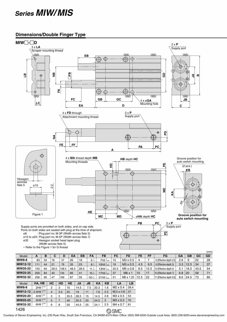
Dimensions/Double Finger Type
MIW�-�D
LC
LB
3 x LAScraper mounting thread
�F
B
EB
FC
NB
EA
GCGB
GD
FA
DMounting hole4 x øGA
JA
C
JB
B
2 x PSupply port
2 x PAttachment mounting thread4 x FD through
Supply port
Hexagon accross flats 5
ø4
HB depth HC
øHA depth HC Groove position forauto switch mounting
(2 pcs.)
Groove position for auto switch mountingMounting threads
4 x MA thread depth MB
ø15
2.2
Figure 1
2 x PSupply portSupply ports are provided on both sides, and on cap side.
Ports on both sides are sealed with plug at the time of shipment. ø8 : Plug part no. M-3P (Width across flats 5) ø12 to ø25: Plug part no. M-5P (Width across flats 7) ø32 : Hexagon socket head taper plug
(Width across flats 5) ∗ Refer to the Figure 1 for G thread
MIW8-8MIW12-12MIW20-20MIW25-25MIW32-32
A B C EA EB FA FB FD FE FF FG GA GB GD83
111
155
200
256
34
44
64
84
95
16
21
29.5
40
47
57
76
106.5
134
169
26
35
48.5
66
87
18
23
28.5
41
55
15
19
25.5
37
51
4 4.5 6.51012.5
6 (Effective depth 2.5)
6 (Effective depth 3)
10 (Effective depth 4)
15 (Effective depth 7)
17 (Effective depth 8.5)
7 9.512.51722
2.63.35.16.88.6
912.516.52024.5
2837547180
223443.55873
M3 x 0.5M3 x 0.5M5 x 0.8M6 x 1
M8 x 1.25
D FC GC6
8
11
15
19.5
0-0.1
0-0.1
0-0.1
0-0.1
0-0.1
7h9
10h9
13h9
17h9
21h9
0-0.036
0-0.036
0-0.043
0-0.043
0-0.052
Model
MIW8-8MIW12-12MIW20-20MIW25-25MIW32-32
Model
(mm)
HA, HB2H9
2.5H9
4H9
5H9
6H9
+0.025 0
+0.025 0
+0.030 0
+0.030 0
+0.030 0
HC2
4
5
5
6
HD HE JA JB3
3.5
5
7
8
15
25
35.5
40
50
14.5
19
28.5
35.5
44.5
7.5
11
15
20
25
KA20.3
7.6
14.5
24.5
24.1
KB1.6
2.2
2.8
3
2.5
LB28.4
37
53
70
81
LAM2 x 0.4M2.6 x 0.45M3 x 0.5M3 x 0.5M4 x 0.7
1426
Series MIW/MIS
P1371-P1434-E.qxd 08.11.17 3:43 PM Page 1426
Courtesy of Steven Engineering, Inc.-230 Ryan Way, South San Francisco, CA 94080-6370-Main Office: (650) 588-9200-Outside Local Area: (800) 258-9200-www.stevenengineering.com
SC
SA
SB
FC
FC
FFFE
FFFE
FA
FFFE
RG
RD
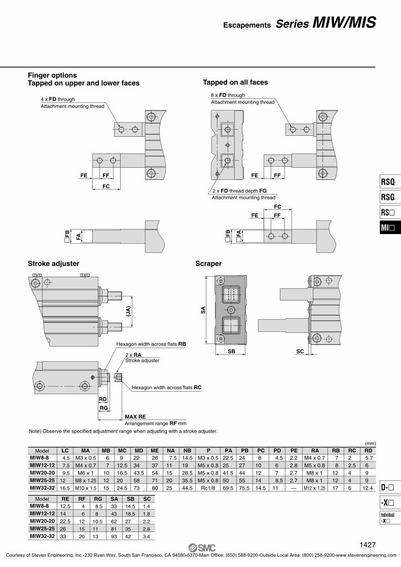
Finger optionsTapped on upper and lower faces Tapped on all faces
Stroke adjuster Scraper
Attachment mounting thread2 x FD thread depth FG
Attachment mounting thread8 x FD through
Attachment mounting thread4 x FD through
Note) Observe the specified adjustment range when adjusting with a stroke adjuster.
(JA
)
Arrangement range RF mm
Hexagon width across flats RC
Hexagon width across flats RB
2 x RAStroke adjuster
MAX RE
MIW8-8MIW12-12MIW20-20MIW25-25MIW32-32
LC MA MB MC MD ME NB 4.5
7.5
9.5
12
16.5
67
101215
912.516.52024.5
223443.55873
2837547180
14.51928.535.544.5
7.511152025
M3 x 0.5M4 x 0.7M6 x 1
M8 x 1.25M10 x 1.5
PA22.52541.55069.5
PB2427445575.5
PC 810121414.5
PD4.5678.5
11
PE2.22.82.72.7—
RB78
121217
RC22.5446
RD5.7699
12.4
RAM4 x 0.7M5 x 0.8M8 x 1M8 x 1
M12 x 1.25
PM3 x 0.5M5 x 0.8M5 x 0.8M5 x 0.8
Rc1/8
NAModel
MIW8-8MIW12-12MIW20-20MIW25-25MIW32-32
Model
(mm)
RF RG SA SB4
6
12
15
20
8.5
8
10.5
11
13
33
43
62
81
93
14.5
18.5
27
35
42
SC1.4
1.8
2.2
2.8
3.4
RE12.51422.52633
�F
B
�FA
�F
B
1427
Escapements Series MIW/MIS
RSQ
RSG
RS�
MI�
Individual-X�
D-�
-X�
P1371-P1434-E.qxd 08.11.17 3:43 PM Page 1427
Courtesy of Steven Engineering, Inc.-230 Ryan Way, South San Francisco, CA 94080-6370-Main Office: (650) 588-9200-Outside Local Area: (800) 258-9200-www.stevenengineering.com

N
HE
HD
PB
LC
LB
EB
PD KB
KA
GD
PEGCGB
FC
EA
FA
A
FFFE
ME
JB
MD
JA
CD
PA
PC
B
MC
PA PB
PD
PC
Dimensions/Single Finger Type
MIS�-�D
�F
B
Scraper mounting thread2 x LA Mounting hole
Supply port
2 x øGA
2 x P
Attachment mounting thread2 x FD through
(2 pcs.)
Groove position for auto switch mounting
ø4
Groove position forauto switch mounting
HB depth HC
øHA depth HC
4 x MA thread depth MBMounting thread
Supply port2 x P
ø15
2.2
Figure 1
Hexagon accross flats 5
Supply ports are provided on both sides.A port on a side is sealed with plug at the time of shipment. ø8 : Plug part no. M-3P (Width across flats 5) ø12 to ø25: Plug part no. M-5P (Width across flats 7) ø32 : Hexagon socket head taper plug
(Width across flats 5) ∗ Refer to the Figure 1 for G thread
6(Effectivedepth 2.5)
6(Effectivedepth 3)
10(Effectivedepth 4)
15(Effectivedepth 7)
17(Effectivedepth 8.5)
FGFB
M3 x 0.5
M3 x 0.5
FD
19
15
3.3
2.6
8 -0.1 0
11 -0.1 0
15 -0.1 0
19.5-0.1 0
6 -0.1 0
10h9 -0.036 0
13h9 -0.043 0
17h9 -0.043 0
21h9 -0.052 0
7h9 -0.036 0
FCFA GA
18
13
5
4
GD HA, HBGCGB
9.5
7
21
16
4.5
M5 x 0.825.5 5.1 712.5 6.5
M6 x 137 6.8 101710
M8 x 1.2551 8.6 12
25
28
342212.5
4
23
28.5
41
55
18
FFFEEBEAD
26
29.535
41
50
40
47
19203028384832425255756484
28 38 33 43 53 38.5 48.5 58.5 71 91 85105
59 79 72 92112 86.5106.5126.5144184165205
MIS8-10MIS8-20MIS12-10MIS12-20MIS12-30MIS20-10MIS20-20MIS20-30MIS25-30MIS25-50MIS32-30MIS32-50
CBA87
117105135165125155185215270250310
Model
2H9 0+0.025
2.5H9 0+0.025
4H9 0+0.030
5H9 0+0.030
6H9 0+0.030
1428
Series MIW/MIS
P1371-P1434-E.qxd 08.11.17 3:43 PM Page 1428
Courtesy of Steven Engineering, Inc.-230 Ryan Way, South San Francisco, CA 94080-6370-Main Office: (650) 588-9200-Outside Local Area: (800) 258-9200-www.stevenengineering.com

SBSC
SA
FC
FFFE
FFFE
FC
FA
FFFE
RD
RA
RE
Finger optionsTapped on upper and lower faces Tapped on all faces
�F
B�F
B �FA
Attachment mounting threadFD thread depth FG
With scraperWith adjuster
Attachment mounting thread4 x FD through
Attachment mounting thread
2 x FD through
Arrangement range RF mm
Hexagon width across flats RC
Hexagon width across flats RB
Stroke adjuster
M2.6 x 0.45
M2 x 0.4
LA
11.6
6.2
19
14
KA LB
18
13
4
3
MEMDLC
17.5
14
2.2
M3 x 0.514 26 62.8
M3 x 0.511 32 103
M4 x 0.720.4 39
7
5
MB
10
14
15
5
4
MC
7
10
1212
25
28
34
11
7.5
N
15
20
25
6
4.5
PC
8
12
11
10
8
PB
12
14
14.52.5
1.6
11
15
20
25
7.5
13
17.5
20.5
25
9.5
KBJBJA
3.5
265
7
8
32
40
3
4
5
5
6
2203028384832425255756484
PA192919293920.530.540.547674767
MIS8-10MIS8-20MIS12-10MIS12-20MIS12-30MIS20-10MIS20-20MIS20-30MIS25-30MIS25-50MIS32-30MIS32-50
HEHDHC
M4 x 0.7
M3 x 0.5
MA
M6 x 1
M8 x 1.25
M10 x 1.5
M5 x 0.8
M3 x 0.5
P
M5 x 0.8
M5 x 0.8
Rc1/8
Model
2.8
2.2
PE
14
12.5
RERD
2.7
2.7
—
8
7
RB
12
12
17
2.5
2
RC
4
4
6
6
5.7
9
9
12.4
22.5
26
33
1.8
1.4
SC
2.2
2.8
3.4
6
4
RF
12
15
20
8
8.5
10.5
11
13
18
14
SB
26
36
41
24
18.6
SA
34
40
49
RGMIS8-10MIS8-20MIS12-10MIS12-20MIS12-30MIS20-10MIS20-20MIS20-30MIS25-30MIS25-50MIS32-30MIS32-50
M5 x 0.8
M4 x 0.7
RA
M8 x 1
M8 x 1
M12 x 1.25
Model
Note) Observe the specified adjustment range when adjusting with a stroke adjuster.
7
6
PD
10
14
27
1429
Escapements Series MIW/MIS
RSQ
RSG
RS�
MI�
Individual-X�
D-�
-X�
P1371-P1434-E.qxd 08.11.17 3:43 PM Page 1429
Courtesy of Steven Engineering, Inc.-230 Ryan Way, South San Francisco, CA 94080-6370-Main Office: (650) 588-9200-Outside Local Area: (800) 258-9200-www.stevenengineering.com
E
C
A
B
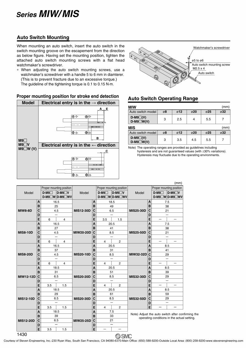
3 2.5 4 5.5 7D-M9�(V)D-M9�W(V)
MIW
3 3.5 4.5 5.5 7
MIS
Auto Switch Mounting
When mounting an auto switch, insert the auto switch in the switch mounting groove on the escapement from the direction as below figure. Having set the mounting position, tighten the attached auto switch mounting screws with a flat head watchmaker’s screwdriver.∗ When adjusting the auto switch mounting screws, use a
watchmaker’s screwdriver with a handle 5 to 6 mm in diamterer.(This is to prevent fracture due to an excessive torque.) The guideline of the tightening torque is 0.1 to 0.15 N·m.
Proper mounting position for stroke end detection Auto Switch Operating Range
Watchmaker’s screwdriver
ø5 to ø6
Auto switch
M2.5 x 4Auto switch mounting screw
(mm)
(mm)
Auto switch model ø8 ø12 ø20 ø25 ø32
Auto switch model ø8 ø12 ø20 ø25 ø32
Note) The operating ranges are provided as guidelines including hysteresis and are not guaranteed values (with ±30% variations).Hysteresis may fluctuate due to the operating environments.
Electrical entry is in the direction
Electrical entry is in the direction
Model
Model
Proper mounting position
D-M9�D-M9�W
D-M9�VD-M9�WV
16.5254.5�
16.5274.5�
16.5374.5�
18.5316.5�
18.5296.5�
18.5396.5�
MIW8-8D
MIS8-10D
MIS8-20D
MIW12-12D
MIS12-10D
MIS12-20D
ABCDEABCDEABCDEABCDEABCDEABCDE
6 4
6 4
6 4
3.5 1.5
3.5 1.5
3.5 1.5
Model
Proper mounting position
D-M9�D-M9�W
D-M9�VD-M9�WV
18.5496.5�
20.5418.5�
20.5318.5�
20.5518.5�
20.5618.5�
7.53321�
MIS12-30D
MIW20-20D
MIS20-10D
MIS20-20D
MIS20-30D
MIW25-25D
ABCDEABCDEABCDEABCDEABCDEABCDE
3.5 1.5
4 2
4 2
4 2
4 2
� �
Model
Proper mounting position
D-M9�D-M9�W
D-M9�VD-M9�WV
7.53821�
7.53821�
8.54129�
8.53929�
8.55929�
MIS25-30D
MIS25-50D
MIW32-32D
MIS32-30D
MIS32-50D
ABCDEABCDEABCDEABCDEABCDE
� �
� �
� �
� �
� �
(mm)
M9�M9�VM9�W (V)
D-M9�(V)D-M9�W(V)
Note) Adjust the auto switch after confirming the operating conditions in the actual setting.
1430
Series MIW/MIS
P1371-P1434-E.qxd 08.11.17 3:43 PM Page 1430
Courtesy of Steven Engineering, Inc.-230 Ryan Way, South San Francisco, CA 94080-6370-Main Office: (650) 588-9200-Outside Local Area: (800) 258-9200-www.stevenengineering.com

3. Please observe the specified torque limits when tightening screws to mount the attachment.A tightening torque above the specified limits can cause malfunction, while a tightening torque below the specified limits can cause dislocation or drop off.
Mounting
1. Design the attachment to be light and short.1) A long and heavy attachment can cause a large inertia
force in operation, sometimes affecting the life time.2) Design the attachment to be as short and light as possible
even within the limitation.
Warning
Mounting
1. When mounting an attachment on the finger, sup-port the finger with a tool like a spanner to prevent twisting.
Otherwise malfunction may result.
2. Please do not scratch or gouge the sliding part of the finger.It may increase the sliding resistance or cause abrasion.
3. Use a speed controller, etc. to keep the operating speed of the finger within the proper range.Otherwise the life time may be adversely affected by inertia force of the attachment.
4. Conduct meter-out control to throttle down the speed. Applicable speed controller Direct connection type –AS120� Piping type – AS1001F Direct connection type –AS220� Piping type – AS2001F etc.
Caution
1. Do not scratch or gouge the escapement by drop-ping or bumping it when mounting.Even a slight deformation can cause inaccuracy or malfunction.
2. Please observe the specified torque limits when tightening screws to mount the attachment.A tightening torque beyond the specified limits can cause malfunction, while a tightening torque below the specified limits can cause dislocation or drop off.
Warning
When mounting an attachment on the finger, support the finger with a tool like a spanner to prevent twisting.Mount attachments by inserting bolts, etc. into the female mounting threads on the fingers and tightening with the torque shown in the table below.
Mounting attachment on finger
Body through hole
Model
MIW8MIS8MIW12MIS12MIW20MIS20MIW25MIS25MIW32MIS32
Bolt
M3 x 0.5
M4 x 0.7
M6 x 1
M8 x 1.25
M10 x 1.5
Max tighteningtorque (N⋅m)
0.88
0.63
1.5
5.2
12.5
24.5
Max screw-in depth (mm)
6
4.5
6
9
12
15
ModelMIW8MIS8MIW12MIS12MIW20MIS20MIW25MIS25MIW32MIS32
Bolt
M3 x 0.5
M3 x 0.5
M5 x 0.8
M6 x 1
M8 x 1.25
Max tightening torque (N⋅m)
0.88
0.88
4.3
7.3
17.5
ModelMIW8MIS8MIW12MIS12MIW20MIS20MIW25MIS25MIW32MIS32
Bolt
M2.5 x 0.45
M3 x 0.5
M5 x 0.8
M6 x 1
M8 x 1.25
Max tightening torque (N⋅m)
0.5
0.88
4.3
7.3
17.5
Selection
Mounting
Body tap
Series MIW/MISSpecific Product Precautions 1Be sure to read before handling. Refer to front matters 42 and 43 for Safety Instructions and pages 3 to 11 for Actuator and Auto Switch Precautions.
1431
RSQ
RSG
RS�
MI�
Individual-X�
D-�
-X�
P1371-P1434-E.qxd 08.11.17 3:43 PM Page 1431
Courtesy of Steven Engineering, Inc.-230 Ryan Way, South San Francisco, CA 94080-6370-Main Office: (650) 588-9200-Outside Local Area: (800) 258-9200-www.stevenengineering.com

2. Be sure to use specified adjuster bolts for replacement.Otherwise, fracture may be caused by an impact etc.
3. Refer to the table below for the lock nut tightening torque.Insufficient tightening can cause air leakage.
1. Observe the specified adjustment range as shown on right when adjusting with a stroke adjuster.Bolts may shoot out when adjusting stroke adjuster over the maximum stroke as shown on right. Be sure to observe the specified adjustment range, otherwise malfunction may results.
Warning
Model
MIW8MIS8MIW12MIS12MIW20MIS20MIW25MIS25MIW32MIS32
Tightening torque (N⋅m)
1.2 to 1.5
2.5 to 3.0
10.5 to 12.5
10.5 to 12.5
34 to 42
Stroke adjuster
Changing of Piping Directions
Pressured from A port Finger A extends, finger B retractsPressure from B port Finger B extends, finger A retracts
Supply port operation
Model
MIW8MIS8
MIW12MIS12MIW20MIS20MIW25MIS25MIW32MIS32
Port size
Rc1/8
How to tight
Turn another 1/4 turn with a tool after manual tightening.
Turn another 1/6 turn with a tool after manual tightening.
Tightening torque 7 to 9 N•m
Handling of Adjuster Options
Handling of Adjuster Options Operating Environment
1. Do not use in an environment where the product is directly exposed to liquid such as cutting lubricant.Avoid use in an environment where the product is exposed to cutting lubricant, liquid coolant or oil mist. It can cause rattles, increase in sliding resistance and air leakage.
2. Do not use in an environment where the product is directly exposed to foreign matter such as dust, coarse particular, chips and polishing powder from a spatter grinder, etc.It can cause rattles, increase in sliding resistance and air leakage.
Caution
1. Please observe the specified torque limits when tightening a plug to change the piping directions.A tightening torque above the specified limits can cause a damage to the plug, while tightening torque below the specified limits can cause a damage to seal or the screw come loose during the operation.
M5 x 0.8Plug part no:
M-5P
M3 x 0.5Plug part no:
M-3P
Model
MIW8MIS8MIW12MIS12MIW20MIS20MIW25MIS25MIW32MIS32
At the maximum
stroke (mm)
At the maximum
adjustment (mm)
Adjustment range (mm)
12.5
14
22.5
26
33
4
6
12
15
20
8.4
8
10.5
11
13
Caution
Adjustment range
Maximum adjustment range
At the maximum stroke
Finger B
Port A Port B
Finger A
Finger A
Port A
Port B
Port APort B
Port APort B
Port APort B
Series MIW/MISSpecific Product Precautions 2Be sure to read before handling. Refer to front matters 42 and 43 for Safety Instructions and pages 3 to 11 for Actuator and Auto Switch Precautions.
1432
P1371-P1434-E.qxd 08.11.17 3:43 PM Page 1432
Courtesy of Steven Engineering, Inc.-230 Ryan Way, South San Francisco, CA 94080-6370-Main Office: (650) 588-9200-Outside Local Area: (800) 258-9200-www.stevenengineering.com
Series MIW/MISSpecific Product Precautions 3Be sure to read before handling. Refer to front matters 42 and 43 for Safety Instructions and pages 3 to 11 for Actuator and Auto Switch Precautions.
1. Please observe the specified torque limits when mounting a scraper.A tightening torque above the specified limits can cause a damage, while tightening torque below the specified limits can cause a dislocation or drop off.
Scraper Option
Caution
Tightening torque1. Keep away hands and other body parts from the fin-
gers of the escapement or movement range of the attachment.It can lead to an injury or accident.
2. When removing the escapement, first block off or remove the work piece on the primary side of the escapement, release compressed air and remove it.If the work piece remains, it can be transferred by mistake and cause failure to the equipment on the secondary side.
Warning
1. The non-lubricant type escapement is lubricated at the factory and does not need further lubrication for use.In case the product is lubricated by the customer, apply class 1 turbin oil (non additive) ISO VG32.In case the product is lubricated by the customer, be sure to continue lubrication.If it is discontinued, malfunction may result due to loss of initial lubricant.
Caution
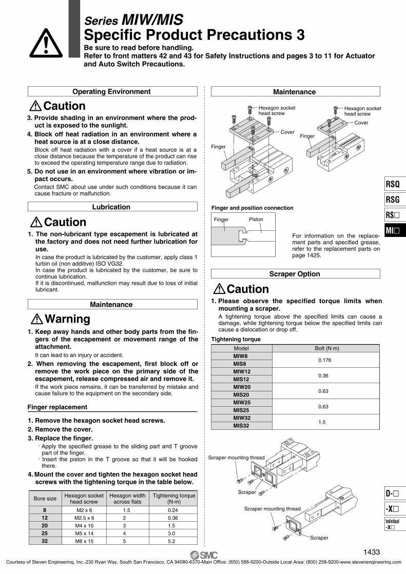
1. Remove the hexagon socket head screws.2. Remove the cover.3. Replace the finger.
. Apply the specified grease to the sliding part and T groove part of the finger.
. Insert the piston in the T groove so that it will be hooked there.
4. Mount the cover and tighten the hexagon socket head screws with the tightening torque in the table below.
Finger replacement
Lubrication
Maintenance
Maintenance
Bore size
812202532
Hexagon sockethead screw
Hexagon widthacross flats
Tightening torque(N⋅m)
M2 x 6
M2.5 x 6
M4 x 10
M5 x 14
M6 x 15
1.5
2
3
4
5
0.24
0.36
1.5
3.0
5.2
For information on the replace-ment parts and specified grease, refer to the replacement parts on page 1425.
3. Provide shading in an environment where the prod-uct is exposed to the sunlight.
4. Block off heat radiation in an environment where a heat source is at a close distance.Block off heat radiation with a cover if a heat source is at a close distance because the temperature of the product can rise to exceed the operating temperature range due to radiation.
5. Do not use in an environment where vibration or im-pact occurs.
Contact SMC about use under such conditions because it can cause fracture or malfunction.
CautionOperating Environment
ModelMIW8MIS8MIW12MIS12MIW20MIS20MIW25MIS25MIW32MIS32
Bolt (N⋅m)
0.176
0.36
0.63
0.63
1.5
Scraper mounting thread
Scraper
Scraper mounting thread
Scraper
Hexagon socket head screw
Hexagon socket head screw
Cover
Finger
Finger
Cover
Finger and position connection
Finger Piston
1433
RSQ
RSG
RS�
MI�
Individual-X�
D-�
-X�
P1371-P1434-E.qxd 08.11.17 3:43 PM Page 1433
Courtesy of Steven Engineering, Inc.-230 Ryan Way, South San Francisco, CA 94080-6370-Main Office: (650) 588-9200-Outside Local Area: (800) 258-9200-www.stevenengineering.com