
b - Medidor Rotatorio
8
ROTARY PISTON GAS METER IRM-3 M-IRM 3-4 ROTARY PISTON GAS METER IRM - 3 NATIONAL ACCREDITATION OF CERTIFICATION BODIES E
Transcript of b - Medidor Rotatorio

RO
TARY
PIS
TON
GA
S M
ETER
IRM
-3M
-IRM
3-4
ROTARY PISTONGAS METERIRM - 3
NATIONALACCREDITATION
OF CERTIFICATIONBODIES
E

2
INTRODUCTIONInstromet International is proud to introduce the latest member of the Instromet family of positive displacementrotary piston meters. As an alternative to the popular cartridge, Instromet engineers have developed a verycompact design that minimises the leakage of gas through the measurement chamber and maximises thevolume transferred by the rotors. The result is the IRM 3, a meter of remarkable performance.The IRM 3’s body is exceptionally rigid and will not be deformed by misalignment in the installation that could,in conventional rotary meters, cause the rotors to block. Special consideration has also been given to the servicemaintainer of the IRM 3 with special features that assist his task.The meter is robust, accurate and has a turn down ratio that can only be surpassed by an internal cartridgedesign. It is certified for custody transfer applications.
OUTSTANDING FEATURES
EXTRAORDINARYTURN DOWN RATIOFor all rotary meters, the performanceat lower capacities is determined bythe amount of gas leaking across therotors. The turn down ratio that canbe achieved by a meter is inverselyproportional to this unregistered gas;the smaller the leakage, the greaterthe meter’s range. Instromet’s newradical design allows as little gas aspossible to leak through themeasurement chamber giving thebest turn down ratio of allconventional meters. The IRM 3 hasalso a number of unprecedentedfeatures. The most striking aspect of the IRM3 is the “square shape” of the rotorswhere the length of each rotor isequal to its width. The rotors thuscontain the largest possible volumeof gas for the smallest outline profileand this reduces to a minimum theareas where unregistered gas canpass. The two lobes of the rotorsbeing larger have wider tips thatagain reduces the leakage.The rotors revolve at a slower speedfor an equivalent flow rate thusincreasing the life of the bearingsand making the meter noticeably quieter.
3” G100 (7M)
The “square” profile of the IRM 3 rotor
(L) compared to a conventional (R)

3
INSENSITIVE TO INSTALLATION STRESSESNormally the most vulnerable feature of a conventional rotary meter is the body’s sensitivity to stresses causedby the installation. With all aluminium rotary meters (except for the cartridge design) even small misalignmentsin the installation can distort the body thereby altering the rotor clearances and in severe cases causing therotors to block. To avoid this effect, special attention must be given to construction of the meter body as thematerial normally used (aluminium) tends to deform under stress. The IRM 3 has massive end plates giving themeter such a rigidity that the performance of the meter is not affected under conditions of bending, torsion orvibration.
The design of the bodyalso deadens the soundcaused by the internalmoving parts andcontributes to themeter’s quietness.
EXTREMELY ROBUSTAlthough a meter is a precision instrument it can be subjected under field conditions to rough handling andmistreatment such as overloading the meter, flow and pressure shocks, impurities in the gas etc. Under thesecircumstances the rotors or the rotor shafts will bend or twist resulting in their locking with subsequent seriousdamage. The short square construction is highly resistant to this kind of abuse.
In most rotary meter types the weakestpart of the internal construction isusually the main shaft. These shafts onwhich the timing gears are fitted have aparticular tendency to twist due to theirnarrow diameter. Since the main bearingis fitted on the shaft between the rotorand the timing gear, the diameter of theshaft and therefore its strength is limitedto the internal dimensions of thebearing. Increasing the diameter of theshaft and thus its strength would requirea larger bearing with consequentialdetriment to the turn down ratio.
The IRM 3 uses a radical different concept. In the IRM 3 the timing gear is fitted between the rotor and themain bearing, thereby removing any limit to the size of the shaft. The resultant resistance to twisting is at least10 times higher than in other meters thus making the IRM 3 less sensitive to meter mistreatment.
The Robust Construction
Timing Gear
Bearing
The bearings can be replaced without disturbing the timing gear
Internal end plates
EASE OF MAINTENANCE AND REPAIRThe modified position of the bearings gives the IRM 3 another unique advantage. By placing the timing gearsbetween the rotor and the main bearing the meter can be disassembled and the bearings can be replacedwithout removing the timing gears from the shaft. During disassembling the timing is not disturbed, makingbearing replacement a fast and easy job even for less experienced shops.
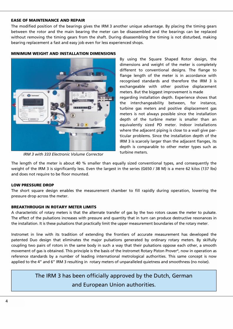
MINIMUM WEIGHT AND INSTALLATION DIMENSIONSBy using the Square Shaped Rotor design, thedimensions and weight of the meter is completelydifferent to conventional designs. The flange toflange length of the meter is in accordance withrecognised standards and therefore the IRM 3 isexchangeable with other positive displacementmeters. But the biggest improvement is made regarding installation depth. Experience shows thatthe interchangeability between, for instance,turbine gas meters and positive displacement gasmeters is not always possible since the installationdepth of the turbine meter is smaller than anequivalently sized PD meter. Indoor installationswhere the adjacent piping is close to a wall give par-ticular problems. Since the installation depth of theIRM 3 is scarcely larger than the adjacent flanges, itsdepth is comparable to other meter types such asturbine meters.
The length of the meter is about 40 % smaller than equally sized conventional types, and consequently theweight of the IRM 3 is significantly less. Even the largest in the series (G650 / 38 M) is a mere 62 kilos (137 lbs)and does not require to be floor mounted.
LOW PRESSURE DROPThe short square design enables the measurement chamber to fill rapidly during operation, lowering thepressure drop across the meter.
BREAKTHROUGH IN ROTARY METER LIMITSA characteristic of rotary meters is that the alternate transfer of gas by the two rotors causes the meter to pulsate.The effect of the pulsations increases with pressure and quantity that in turn can produce destructive resonances inthe installation. It is these pulsations that practically limit the upper measurement boundaries of the rotary meter.
Instromet in line with its tradition of extending the frontiers of accurate measurement has developed thepatented Duo design that eliminates the major pulsations generated by ordinary rotary meters. By skilfullycoupling two pairs of rotors in the same body in such a way that their pulsations oppose each other, a smoothmovement of gas is obtained. This principle is the basis of the Instromet Rotary Piston Prover®, now in operation asreference standards by a number of leading international metrological authorities. This same concept is nowapplied to the 4” and 6” IRM 3 resulting in rotary meters of unparalleled quietness and smoothness (no noise).
4
IRM 3 with 333 Electronic Volume Corrector
The IRM 3 has been officially approved by the Dutch, German
and European Union authorities.

5
The two sine curves represent thepulsations of the two sets ofrotors. The rotors aresynchronised so that the sinecurves are in opposite phases.
The dual rotors are standard in theG 400 and G 650 (23 M and 38 M) andoptional in the G 250 (16 M).
All aluminium surfaces are hardanodised for maximum protectionagainst corrosion and wear.
OTHER FEATURESTwo Index options are presently available, the economical Compact Index and the novel Universal Index. Aneight digit mechanical counter and low frequency pulse digit sensor are fitted as standard in both index models.The universal index has the added feature that the meter can read the gas flow from either direction without
changes to the meter itself. Such ameter can therefore be installed foreither left, right, top or bottom flowentry. This flexibility greatly reducesinventory requirements.
• Two thermal wells fortemperature probes arestandard.
• The meter is lubricated forup to ten years continuousservice.
IRM 3 with the Compact Index

6
PRINCIPAL OPERATING CHARACTERISTICS
Accuracy:less than 1. 0 % uncertainty
Repeatability:better than 0.1 %
Rangeability:greater than 1 :100
Flange rating:PN 16 - ANSI 150
Max. operating pressure:16 bar - 232 psi
Gas Temperature Range :-30° C to +60° C / -22° F to 140° F Other temperature ranges on request.
Flow Range:G 25 to G 650 / 1.5 M - 38M(0.6 m3/h - 1,000 m3/h) / (20 cfh - 38,000 cfh)6” G650 (38 M)
Temperature Well
Pressure Point
Oil Filling
Pressure Point
Optional HF Pulse Sensor
LF Pulse Sensor
Temperature Well
LF Pulse Sensor
Oil Drain
Front of Meter with Universal Index
Oil Sight-glass

Flow Range LK M No. H BL BT C E WT(lbs)
1.5 M 11/2 “& 2” 4 8 6 3/4 9 5 1/3 3 1/2 23
2 M 11/2” & 2” 4 8 6 3/4 9 5 1/3 3 1/2 23
3 M 2 “ 4 3/45/8 4 8 6 3/4 9 5 1/3 3 1/2 23
5 M / 7 M 3” 6 5/8 4 8 6 3/4 11 3/8 6 5/8 4 3/4 26
7 M / 11 M 3” 6 5/8 4 12 1/8 9 1/2 12 6 3/4 5 1/4 63
16 M 4” 7 1/25/8 8 12 1/8 9 1/2 13 1/2 7 2/3 5 7/8 69
23 M 4” 7 1/25/8 8 12 1/8 9 1/2 18 3/8 10 1/2 7 7/8 101
23 M 6” 9 1/23/4 8 12 1/8 10 1/4 18 3/8 10 1/2 7 7/8 110
38 M 6” 9 1/23/4 8 12 1/8 10 1/4 23 1/2 13 1/8 10 3/8 137
Flow Range LK M No. H BL BT C E WT (kg)
G 25 11/2 “& 2” 110 M16 4 202 171 228 137 91 11
G 40 11/2” & 2” 110 M16 4 202 171 228 137 91 11
G 65 2 “ 125 M16 4 202 171 228 137 91 11
G 100 3” 160 M16 8 202 171 290 168 122 14
G 160 3” 160 M16 8 308 241 305 175 130 29
G 250 4” 180 M16 8 308 241 343 194 149 32
G 400 4” 180 M16 8 308 241 466 270 196 46
G 400 6” 240 M20 8 308 260 466 270 196 50
G 650 6” 240 M20 8 308 260 598 336 262 62
All dimensions are in mm unless otherwise indicated. No. = Number of bolts.
7
125
125
DIN FLANGES
ANSI FLANGES
All dimensions are in inches unless otherwise indicated. No. = Number of bolts.
3 1/8
4 3/4
1/2
5/8
3 1/8
4 3/4
1/2
5/8
DIMENSIONS

Sales Offices:In Argentina:INSTROMET S.A.
In Australia:INSTROMET SYSTEMS AUSTRALIA PTY. LTD.
In Austria:INSTROMET B.V. GES.M.B.H.
In Belgium:INSTROMET INTERNATIONAL N.V.
In Brazil:INSTROMET MEDIÇÃO E CONTROLE LTDA.
In Croatia:INSTROMET CROATIA
In France:INSTROMET S.A.R.L.
In Germany:INSTROMET G.M.B.H.
In Hungary:INSTROMET HUNGARY SERVEX HUNGARY KFT.
In India:SIDDHA GAS INSTROMET INDIA PVT. LTD.
In Italy:INSTROMET ITALIA S.R.L.
In Korea:INSTROMET KOREA LTD.
In Malaysia:INSTROMET INTERNATIONALREGIONAL OFFICE, SOUTH EAST ASIA
In the Netherlands:INSTROMET B.V.
In Nigeria:INSTROMET WEST AFRICA B.V.
In Poland:INSTROMET POLSKA
In Portugal:INSTROMET PORTUGAL LDA.
In Spain:INSTROMET ACUSTER S.L.
In Switzerland:INSTROMET AG.
In the UK:INSTROMET UK
In the Ukraine:INSTROMET UKRAINE LTD.
In the USA:INSTROMET INC.
Products & Services:● Ultrasonic gas meters
● Turbine gas meters
● Rotary gas meters
● Insertion gas meters
● Electronic volume correctors
● Flow computer systems
● Calorimeters
● Gas chromatographs
● Supervisory Systems
● Gas filters
● Gas pressure regulators
● Safety shut-off valves
● Telemetering systems
● Electronic metering and control systems
● Calibration and test installations
● Complete gas measurement and control stations
● Commissioning, servicing, training and consulting
2010
00 C
opyr
ight
© In
stro
met
/ Ro
oduy
n V
orm
& D
ruk
The
Net
herla
nds
INSTROMET has agents and representatives worldwide.
INSTROMET has a continuing program of product research and development.Technical specifications and construction may change due to improvements.This publication serves as general information only, and all specifications aresubject to confirmation by INSTROMET.
YOUR SALES OFFICE OR REPRESENTATIVE:
Gas measurement and control equipment
For your nearest sales office orrepresentative please contact:INSTROMET INTERNATIONALRijkmakerlaan 9 - B-2910 ESSEN - BELGIUMTel: +32 3 6700 700 - Fax : +32 3 667 6940E-mail: [email protected]: http://www.instromet.com


![Horno Rotatorio[1][1]](https://static.fdocuments.ec/doc/165x107/553c3d524a7959473a8b4836/horno-rotatorio11.jpg)
