
EUROCONTROL EXPERIMENTAL CENTRE€¦ · DOVE 1 Fast-Time Simulation EUROCONTROL Project...
74
The information contained in this document is the property of the EUROCONTROL Agency and no part should be reproduced in any form without the Agencys permission. The views expressed herein do not necessarily reflect the official views or policy of the Agency. EUROPEAN ORGANISATION FOR THE SAFETY OF AIR NAVIGATION EUROCONTROL EUROCONTROL EXPERIMENTAL CENTRE DOVE 1 FAST-TIME SIMULATION EEC Report No. 381 Project AGC-Z-DO-0000 Issued: May 2003
Transcript of EUROCONTROL EXPERIMENTAL CENTRE€¦ · DOVE 1 Fast-Time Simulation EUROCONTROL Project...

The information contained in this document is the property of the EUROCONTROL Agency and no part shouldbe reproduced in any form without the Agency�s permission.
The views expressed herein do not necessarily reflect the official views or policy of the Agency.
EUROPEAN ORGANISATIONFOR THE SAFETY OF AIR NAVIGATION
EUROCONTROL
EUROCONTROL EXPERIMENTAL CENTRE
DOVE 1 FAST-TIME SIMULATION
EEC Report No. 381
Project AGC-Z-DO-0000
Issued: May 2003


REPORT DOCUMENTATION PAGE
Reference:EEC Report No. 381
Security Classification:Unclassified
Originator:EEC � SSP(Sector Safety and Productivity)
Originator (Corporate Author) Name/Location:EUROCONTROL Experimental CentreB.P.15F � 91222 Brétigny-sur-Orge CEDEXFRANCETelephone: +33 (0)1 69 88 75 00
Sponsor:Air/Ground Co-operative Programme(AGC)
Sponsor (Contract Authority) Name/Location:EUROCONTROL AgencyRue de la Fusée, 96B-1130 BrusselsTelephone: +32 2 729 9011
TITLE:
DOVE 1 FAST-TIME SIMULATION
AuthorsPaul Conroy
Date
05/03Pages
xiv + 60Figures
18Tables
5Annexes
-References
3
ProjectAGC-Z-DO-0000
Task No. Sponsor-
Period2001 - 2002
Distribution Statement:(a) Controlled by: Head pf SSP(b) Special Limitations: None(c) Copy to NTIS: YES / NO
Descriptors (keywords):
DOVE - Datalink Operational Validation Experiment � Datalink � Services � EATCHIP � FLIPCY �Monitor
Abstract:
This report describes an EUROCONTROL fast-time simulation study carried out for the AGCProgramme in Brussels, investigating the operational use of datalink services, beyond the scope ofimmediate implementation.The DOVE 1 fast-time simulation was the first in a series of simulations, both real-time and fast-time,that will be carried out at the Eurocontrol Experimental Centre in the coming years.The results showed that the operational impact of datalink services and applications could be significant,especially in terms of reduced R/T communications workload.


DOVE 1 Fast-Time Simulation EUROCONTROL
Project AGC-Z-DO-0000 � EEC Report No. 381 v
SUMMARY
The DOVE 1 fast-time simulation set out to investigate the workload reductions possible forcontrollers, by the introduction of advanced datalink services into their operating environment.
The datalink will provide controllers with a second communication channel to pilots that can bemanaged by either the Tactical or Planning Controller. This facility will enable an evolution of thecontroller working method, transferring Tactical Controller workload to the Planning Controller. It isexpected that reducing the reliance on the radio channel may reduce sector frequency congestion,increase safety, and ultimately enable higher sector capacity.
The anticipated progressive fitting of datalink capability made it necessary to consider a mixed-mode traffic environment, with controllers managing varying levels of both traffic and datalink-equipped aircraft. In this environment, controllers must differentiate between datalink-equippedand non-equipped aircraft, as well as selecting the preferred communication medium for those withdatalink capability.
The technology behind electronic data exchange could enable many different types of datalinkservice. Those services selected for the DOVE1 fast-time simulation were expected to be suitablefor medium and long-range implementation.
The DOVE 1 fast-time simulation investigated these reductions in a series of 18 simulation studies,covering various levels of datalink-equipage and traffic volume, set against a base referencescenario. A reference organisation was established with data [modified] from a previous simulation.It was the airspace of the Czech Republic, modified so as to be in accordance with the objectivesof the DOVE 1 simulation that was modelled. New tasks were established for this referenceorganisation representing controller operations in an electronic environment. This was then usedas a base to measure against.
The benefits associated with the use of a Monitoring message by a datalink-equipped aircraft, andtheir silent arrival into a sector, were explored. Analysis was conducted with equipage rates of50%, 75% and 100%, conducted over both 2002 and 2015 levels of traffic. Assessment of thebenefits was confined to recorded workload only, and did not include matters such as situationalawareness, or delays in datalink responses.
The benefits associated with the use of a VCI message to an aircraft, and their silent departurefrom one sector to another, were also investigated and explored. These runs were also conductedwith 50%, 75% and 100% equipage rates. They were conducted over both 2002 and 2015 levels oftraffic. Again, the benefits were analysed strictly in terms of workload.
These two major changes in tasks were incorporated together, and workload figures produced toindicate the enormous potential [in workload terms] of moving towards a silent operation. Thisexercise indicated the greatest potential of datalink so far, in relation to controller workload.
In these studies, redistribution of tasks across the sector was looked at, as well as redistribution oftasks to the ground system itself.
The provision of extra items of information to the controller, provided by services such as CAP andPPD was explored. Items of information include an aircraft�s heading, or the preferences of thepilot in relation to level or speed.

EUROCONTROL DOVE 1 Fast-Time Simulation
vi Project AGC-Z-DO-0000 - EEC Report No. 381
ATC clearances by datalink were looked at in terms of providing clearances in a non-time criticalroutine manner. The number of these non-time critical messages being used in the environmentwill have a large bearing on the benefits for this service.
How the FLIPCY service might benefit some tactical controllers, by reducing the requirement forcorrective action in the event of aircraft deviation was explored.
In general the studies found potential workload reductions were possible by the introduction ofdatalink services. The extent of these workload reductions varied from service to service.

DOVE 1 Fast-Time Simulation EUROCONTROL
Project AGC-Z-DO-0000 � EEC Report No. 381 vii
ACKNOWLEDGEMENTS
The author would like to take this opportunity to thank all the members of the AGC team inBrussels who were involved in the DOVE model simulation and subsequent real-time simulation.
Thanks are also due to all those in Brétigny-sur-Orge that provided assistance, guidance andencouragement during the course of the simulation.

EUROCONTROL DOVE 1 Fast-Time Simulation
viii Project AGC-Z-DO-0000 - EEC Report No. 381

DOVE 1 Fast-Time Simulation EUROCONTROL
Project AGC-Z-DO-0000 � EEC Report No. 381 ix
TABLE OF CONTENTS
LIST OF FIGURES ........................................................................................................... XII
LIST OF TABLES............................................................................................................. XII
REFERENCES ................................................................................................................ XIII
ABBREVIATIONS ........................................................................................................... XIV
1. INTRODUCTION...........................................................................................................11.1. BACKGROUND.............................................................................................................. 2
2. SIMULATION OBJECTIVES ........................................................................................32.1. MAIN OBJECTIVE.......................................................................................................... 32.2. DETAILED...................................................................................................................... 3
3. SIMULATION CONDUCT .............................................................................................43.1. SIMULATION DATA....................................................................................................... 53.2. STAGE ONE � CREATION OF REFERENCE ORGANISATION .................................. 5
3.2.1. Operational environment and controller tasks ...................................................63.2.2. Manning.............................................................................................................63.2.3. Radar separation standards ..............................................................................63.2.4. Sectors ..............................................................................................................63.2.5. Division Flight Level [DFL].................................................................................73.2.6. Traffic.................................................................................................................73.2.7. Traffic per sector................................................................................................7
3.3. STAGE TWO � INCORPORATING DATALINK TASKS � 2002 TRAFFIC .................... 83.4. STAGE THREE � INCORPORATING DATALINK TASKS � 2015 TRAFFIC ................ 8
4. SERVICES AND APPLICATIONS................................................................................9
5. RAMS CONTROLLER WORKLOAD CALCULATION...............................................115.1. RAMS ........................................................................................................................... 115.2. CONTROLLER PERCENTAGE LOADINGS................................................................ 12
5.2.1. Controller Percentage Loadings � Definition ...................................................12
6. DOVE TASK TIMES....................................................................................................136.1. TASK AND TIMINGS.................................................................................................... 136.2. TASK TABLES ............................................................................................................. 15
6.2.1. Conflict Search Tasks......................................................................................156.2.2. Flight Data Management Tasks.......................................................................156.2.3. Radar Tasks ....................................................................................................156.2.4. R/T Tasks ........................................................................................................166.2.5. Co-ordination Tasks ........................................................................................16
7. RESULTS....................................................................................................................177.1. RESULTS INTRODUCTION ........................................................................................ 17
EUROCONTROL DOVE 1 Fast-Time Simulation
x Project AGC-Z-DO-0000 � EEC Report No. 381
8. VOICE REPLACEMENT STUDIES � 2002 TRAFFIC ................................................188.1. REPLACEMENT OF INITIAL VOICE CONTACT -
DATALINK MONITOR - 100% EQUIPAGE................................................................... 188.1.1. Equipage .........................................................................................................188.1.2. Workload Results ............................................................................................19
8.2. REPLACEMENT OF INITIAL VOICE CONTACT �DATALINK MONITOR - 75% EQUIPAGE...................................................................... 208.2.1. Equipage .........................................................................................................208.2.2. Workload Results ............................................................................................20
8.3. REPLACEMENT OF INITIAL VOICE CONTACT �DATALINK MONITOR - 50% EQUIPAGE...................................................................... 218.3.1. Equipage .........................................................................................................218.3.2. Workload Results ............................................................................................21
8.4. REPLACEMENT OF INITIAL VOICE CONTACT �DATALINK MONITOR � RESULTS OVERVIEW............................................................... 228.4.1. Overall Results ................................................................................................22
8.5. REPLACEMENT OF FINAL VOICE CONTACT � DATALINK VCI -100% EQUIPAGE......................................................................................................... 248.5.1. Equipage .........................................................................................................248.5.2. Workload Results ............................................................................................24
8.6. REPLACEMENT OF FINAL VOICE CONTACT � DATALINK VCI -75% EQUIPAGE........................................................................................................... 258.6.1. Equipage .........................................................................................................258.6.2. Workload Results ............................................................................................25
8.7. REPLACEMENT OF FINAL VOICE CONTACT � DATALINK VCI -50% EQUIPAGE........................................................................................................... 268.7.1. Equipage .........................................................................................................268.7.2. Workload Results ............................................................................................26
8.8. REPLACEMENT OF FINAL VOICE CONTACT � DATALINK VCI �RESULTS OVERVIEW................................................................................................. 278.8.1. Overall Results ................................................................................................27
8.9. REPLACEMENT OF INITIAL AND FINAL VOICE CONTACT �COMBINED OVERVIEW.............................................................................................. 288.9.1. Overall Results ................................................................................................28
9. TASK REDISTRIBUTION STUDIES � 2002 TRAFFIC...............................................319.1. DATALINK TRANSFER - PLANNING CONTROLLER ................................................ 31
9.1.1. General............................................................................................................319.1.2. Equipage .........................................................................................................319.1.3. Workload Results ............................................................................................319.1.4. Specific Results ...............................................................................................32
9.2. DATALINK TRANSFER � SYSTEM TRANSFER OF AIRCRAFT ............................... 339.2.1. General............................................................................................................339.2.2. Equipage .........................................................................................................349.2.3. Workload Results ............................................................................................349.2.4. Specific Results ...............................................................................................35

DOVE 1 Fast-Time Simulation EUROCONTROL
Project AGC-Z-DO-0000 � EEC Report No. 381 xi
10. CAP � CONTROLLER ACCESS PARAMETERS � 2002 TRAFFIC..........................3610.1. GENERAL .................................................................................................................... 36
10.1.1. Method of application ......................................................................................3610.2. RESULTS..................................................................................................................... 37
10.2.1. Workload Results ............................................................................................37
11. PPD � PILOT PREFERENCE DOWNLINKS � 2002 TRAFFIC..................................3811.1. GENERAL .................................................................................................................... 3811.2. RESULTS..................................................................................................................... 38
12. ACL � ATC CLEARANCES AND INSTRUCTIONS � 2002 TRAFFIC .......................3912.1. GENERAL .................................................................................................................... 3912.2. RESULTS..................................................................................................................... 39
12.2.1. Workload Results ............................................................................................3912.2.2. Specific Results ...............................................................................................40
13. FLIPCY - FLIGHT PLAN CONSISTENCY CHECK � 2002 TRAFFIC ........................4113.1. GENERAL .................................................................................................................... 41
13.1.1. Method.............................................................................................................4113.2. RESULTS..................................................................................................................... 42
14. RESULTS OVERVIEW � 2002 TRAFFIC ...................................................................4314.1. RESULTS..................................................................................................................... 43
15. VOICE REPLACEMENT STUDIES � 2015 TRAFFIC ................................................4415.1. REPLACEMENT OF INITIAL AND FINAL VOICE CONTACT � 100% EQUIPAGE .... 44
15.1.1. Workload Results ............................................................................................4515.2. REPLACEMENT OF INITIAL AND FINAL VOICE CONTACT � 75% EQUIPAGE ...... 4615.3. REPLACEMENT OF INITIAL AND FINAL VOICE CONTACT � 50% EQUIPAGE ...... 46
15.3.1. Workload Results ............................................................................................4615.4. REPLACEMENT OF INITIAL AND FINAL VOICE CONTACT � COMBINED
OVERVIEW .................................................................................................................. 4715.4.1. Tactical Controllers..........................................................................................47
16. CONCLUSIONS AND RECOMMENDATIONS...........................................................4816.1. ACM SERVICE............................................................................................................. 48
16.1.1. Replacing initial and final calls.........................................................................4816.1.2. Transfer of Tasks across sector ......................................................................4816.1.3. Transfer of tasks to system .............................................................................4816.1.4. Other Factors...................................................................................................49
16.2. ACL .............................................................................................................................. 4916.3. RESPONSE TIMES...................................................................................................... 4916.4. CAP .............................................................................................................................. 5016.5. PPD .............................................................................................................................. 5016.6. FLIPCY......................................................................................................................... 5016.7. FINALLY....................................................................................................................... 51
FRENCH TRANSLATION (TRADUCTION EN LANGUE FRANÇAISE) ..........................53
EUROCONTROL DOVE 1 Fast-Time Simulation
xii Project AGC-Z-DO-0000 � EEC Report No. 381
LIST OF FIGURES
Figure 1: Organisation of the simulation........................................................................................ 4Figure 2: Sector layout .................................................................................................................. 7Figure 3: Workload - Datalink Monitor - 100% Datalink............................................................... 19Figure 4: Workload - Datalink Monitor - 75% Datalink................................................................. 20Figure 5: Workload - Datalink Monitor - 50% Datalink................................................................. 21Figure 6: Workload - Datalink VCI Transfer - 100% Datalink ...................................................... 24Figure 7: Workload - Datalink VCI and Transfer - 75% Datalink ................................................. 25Figure 8: Workload - Datalink VCI and Transfer - 50% Datalink ................................................. 26Figure 9: Workload - Datalink Monitor and VCI Combined - 100% Datalink ............................... 28Figure 10: Workload - Datalink Monitor and VCI Combined - 75% Datalink ................................. 28Figure 11: Workload - Datalink Monitor and VCI Combined - 50% Datalink ................................. 29Figure 12: Workload - Datalink VCI and Transfer - 75% Datalink - Planning Transfer.................. 32Figure 13: Workload - Datalink Transfer - 75% Datalink - System Transfer.................................. 34Figure 14: Workload - CAP � Controller Access Parameters ........................................................ 37Figure 15: Workload - ACL � ATC Clearances.............................................................................. 40Figure 16: Workload - FLIPCY � Flight Plan Consistency............................................................. 42Figure 17: Workload - Datalink Transfer and Assume Combined - 100% Datalink ....................... 45Figure 18: Workload - Datalink Transfer and Assume Combined - 75% and 50% Datalink.......... 46
LIST OF TABLES
Table 1: Conflict Search Tasks ....................................................................................................... 15Table 2: Flight Data Management Tasks ........................................................................................ 15Table 3: Radar Tasks...................................................................................................................... 15Table 4: R/T Tasks.......................................................................................................................... 16Table 5: Co-ordination Tasks.......................................................................................................... 16

DOVE 1 Fast-Time Simulation EUROCONTROL
Project AGC-Z-DO-0000 � EEC Report No. 381 xiii
REFERENCES
[1] Oze, S., I. Pichancourt, 21 May 2002, DOVE1 System Handbook � Version 1.1, Brétigny-sur-Orge, France, EUROCONTROL Experimental Centre (ACS).
[2] Behier, P., 18 June 2001, Towards Co-operative ATS � The COOPATS Concept, Edition 1.0,Brussels, Belgium, EUROCONTROL-EATMP-AGC Programme.
[3] Roca, J, 02 April 2001, Operational Requirements for Air/Ground Co-operative ATS � Edition1.0, Brussels, Belgium, EUROCONTROL-EATMP-AGC Programme.

EUROCONTROL DOVE 1 Fast-Time Simulation
xiv Project AGC-Z-DO-0000 � EEC Report No. 381
ABBREVIATIONS
Abbreviation De-CodeACC Area Control CentreACL ATC Clearances and InstructionsACM ATC Communications ManagementADAP Automatic Downlink of Aircraft ParametersAGC Air Ground Co-operative ATSATC Air Traffic ControlATS Air Traffic Services
ATSU Air Traffic Services UnitCAP Controller Access Parameters
COOPATS Co-operative ATSCPDLC Central Flow Management Unit
DFL Division Flight LevelDOVE Datalink Operational Validation Experiments
EATCHIP European ATC Harmonisation and Integration ProgrammeECAC European Civil Aviation Conference [area]
EATMP European Air Traffic Management ProgrammeEEC EUROCONTROL Experimental Centre
FDPS Flight Data Processing SystemFIR Flight Information RegionFL Flight Level
FLIPCY Flight Plan Consistency CheckFMS Flight Management SystemFUA Flexible Use of Airspace conceptHMI Human Machine Interface
MONITOR Datalink Monitoring MessageMTCD Medium Term Conflict DetectionNEU North East Upper sectorNM Nautical MilesPPD Pilot Preference Downlinks
RAMS Reorganised ATC Mathematical SimulatorRVSM Reduced Vertical Separation Minimum
R/T Radio TelephonySTATFOR Statistics and Forecasts Panel
STCA Short Term Conflict AlertSYSCO System to System Co-ordination
VCI Voice Change InstructionWSU West South Upper

DOVE 1 Fast-Time Simulation EUROCONTROL
Project AGC-Z-DO-0000 � EEC Report No. 381 1
1. INTRODUCTION
The DOVE 1 fast-time simulation was the first in a series of simulations, both fast time and real-time, requested by the AGC [Air Ground Co-operative ATS] programme in Brussels. The purposeof the simulation, and of the other simulations to be conducted in the future, was to investigate theoperational impact of advanced datalink services and applications, in a European en route ATCenvironment.
Simulation
The fast-time simulation was requested in 2000 and was performed during 2001. It was conductedusing the RAMS simulator at the EUROCONTROL Experimental Centre in Brétigny-sur-Orge.
Airspace
The geographical airspace simulated was based on Czech airspace. However, modifications to theairspace were carried out for the simulation.
The route structure currently existing in Czech airspace provides for many one-way routes. This isdesigned to de-conflict the traffic operating in the airspace. In order to introduce some level ofconflict for the traffic sample, several of these routes were re-aligned together again.
Up to four upper sectors are available to the Czech controllers, to open as traffic demands. In theCzech simulation, an upper airspace structure that had just two sectors covering the ATSU wassuggested as being the best option for them for the future. This sector structure was the one usedby the fast-time simulation, and also by the DOVE real-time simulation that followed.
A division flight level [DFL] of FL285 was chosen to mark the lower boundary of the upperairspace. This was to bring it into line with RVSM airspace requirements.
Because of these changes, and possible future changes in the airspace demanded by the real-timesimulation, the airspace was no longer considered as �Czech�. It was eventually regarded, for thepurpose of the simulations, as being the �DOVE� airspace.
Traffic
Traffic for the simulation was based on a 1997 traffic sample, again originally used for the Czechfast-time simulation in 1998.
This sample was then enhanced to bring it, nominally, to 2002 and 2015 levels.
Timeframe
The services and applications that were tested during the simulation are considered long-termdevelopments in datalink use. Initially the focus of the simulation was on the applications asforeseen in 2015 traffic, with the possibility to investigate them against earlier [lower] traffic levelsas well.
However, after initial simulation runs and given the unrealistic workloads recorded for that level oftraffic forecast for 2015, the focus altered to assessing the workload changes against 2002 trafficlevels first, followed by the 2015 levels.

EUROCONTROL DOVE 1 Fast-Time Simulation
2 Project AGC-Z-DO-0000 � EEC Report No. 381
1.1. BACKGROUND
The DOVE validation projects form part of the operational datalink validation work of the AirGround Co-operative ATS [AGC] Programme, based in EUROCONTROL Head Quarters.
The AGC Programme itself is part of the European Air Traffic Management Programme [EATMP].It develops the Co-operative Air Traffic Services (COOPATS) concept, the associated OperationalRequirements and an implementation strategy to implement COOPATS in the ECAC area.
Datalink technology is seen as the main technical enabler for these developments.
Coupled with automation, and the required improvements in ground-based and airborne-baseddisplays and functionality, datalink will permit the seamless transfer of information betweenairborne and ground-based parties.

DOVE 1 Fast-Time Simulation EUROCONTROL
Project AGC-Z-DO-0000 � EEC Report No. 381 3
2. SIMULATION OBJECTIVES
2.1. MAIN OBJECTIVE
The main objectives identified for the fast-time simulation were to:
• Assess the impact of specific datalink services, developed within the AGC Programme, onoperational workload within en route airspace;
• Feed information into the DOVE real-time simulations.
The objectives were addressed by a series of studies, in which various applications and serviceswere tested to see what benefits they might bring in terms of controller workload reduction.
They were tested in traffic levels equivalent to 2002 and 2015 levels.
The way the applications were simulated, along with timings for tasks, was to be re-assessed afterthe DOVE real-time simulation, scheduled for May 2002.
2.2. DETAILED
In detail, the services and applications being assessed during the fast-time simulation fell into twogroups � CPDLC and ADAP.
• CPDLC [Controller Pilot Data Link Communications] � specifically:
− ACL � ATC Clearances and Instructions.This is a datalink service that allows for pilot request of alterations to a flight�s profile,and also for controller instructions and pilot responses to these instructions.
− ACM � ATC Communications.This service covers the transfer between sectors of both voice and datacommunications.
− CPLDC Automation.This covered the automation of some controller tasks within the CPDLC services.
• ADAP [Automatic Downlink of Aircraft Parameters] � specifically:
− PPD � Pilot Preference Downlinks.This is a datalink service that allows pilots to place requests in front of the controller for,amongst other things, their preferred operating level or speed.
− CAP � Controller Access Parameters.Controller Access Parameters are parameters automatically downlinked from theaircraft that allow the controllers to see the heading, speed and rate of change of anaircraft on their radar display.
− FLIPCY � Flight Plan Consistency.This is a datalink service designed to eliminate discrepancies between flight routesheld in the aircraft [in the aircraft�s FMS] and on the ground [in the ground�s FDPS]. Itdoes this by requesting FMS route information from an aircraft, comparing it to theroute held on the ground, and then warning the controller of any discrepancy.

EUROCONTROL DOVE 1 Fast-Time Simulation
4 Project AGC-Z-DO-0000 � EEC Report No. 381
3. SIMULATION CONDUCT
The DOVE 1 fast-time study used the RAMS simulator, based at the Experimental Centre. Thestudy was conducted in three phases.
Stage 1
The first stage established a reference organisation.
Taking the traffic from a 1998 Czech fast-time simulation and augmenting it to 2002 levels was thefirst step in forming the reference organisation. This augmentation was calculated by STATFOR.
The sectorisation for the reference organisation scenarios was then determined - two upper levelsectors, with a division level of FL285 applied to them.
Lastly, controller tasks were established that reflected those tasks anticipated in the electronicEATCHIP-type environment that is foreseen.
Stage 2
The second stage involved taking the reference organisation and introducing the new datalinkcontroller tasks into it.
The tasks were introduced into scenarios that contained 100%, 75% and 50% datalink equipagerates. During this stage traffic remained at 2002 levels.
Stage 3
The third stage involved applying these new datalink tasks to the future traffic sample, again usingequipage rates of 100%, 75% and 50%
STAGE 1REFERENCE ORG
Traffic levels - 2002
2 Measured Sectors
Division FL285
EATCHIP TasksSTAGE 2
Datalink Tasks - 2002
Traffic levels - 2002
2 Measured Sectors
Division FL285
Datalink TasksSTAGE 3
Datalink Tasks - 2015
Traffic levels - 2015
2 Measured Sectors
Division FL285
Datalink Tasks
Figure 1: Organisation of the simulation

DOVE 1 Fast-Time Simulation EUROCONTROL
Project AGC-Z-DO-0000 � EEC Report No. 381 5
3.1. SIMULATION DATA
In the normal course of events, validation of data used in a simulation study � traffic, airspace, etc.- is carried out by members of a working group, set up specifically for the simulation. The membersof this working group normally comprise controllers from the state or area being simulated, and thesimulation personnel in Brétigny-sur-Orge.
This was not the case for the DOVE 1 fast-time simulation. The working group for the DOVE 1 fast-time simulation comprised members of the AGC Programme in EUROCONTROL headquartersand the simulation personnel in Brétigny-sur-Orge.
Since it was the AGC Programme, and not a specific state that was requesting the simulation, ameeting of the working group was held in January 2001 to determine the simulation environment �including the airspace to be used.
Factors involved in the choice of airspace for the simulation included the fact that no external wayof validating the simulation data was likely to be available and also included the need to keep theairspace environment simulated in the fast-time suitable for simulation at a later date in a real-timeenvironment.
Given these constraints, it was decided to re-use data that had already been used in a previousfast-time simulation. Several options were investigated, but in the end it was decided that the mostsuitable option available for simulation was the Czech airspace, modified to the needs of the DOVEsimulations.
Reasons for this choice included:
• A previously validated base traffic sample.
• A traffic sample that was not overly complex or intense, allowing for practical changes ifrequired.
• Validated geographical and airspace information for that area was already available in theEUROCONTROL facility in Brétigny-sur-Orge.
• Again, an airspace structure that could be easily altered, if required.
• The number of upper sectors that were to be simulated � two � was suitable for use interms of the DOVE real-time simulation. This is because a large-scale simulation,involving a considerable number of controllers, was not foreseen for the DOVE real-timesimulation.
3.2. STAGE ONE � CREATION OF REFERENCE ORGANISATION
The purpose of the reference organisation in a simulation is two-fold. In it the airspace structure,traffic and operational conditions are simulated, and this organisation is then used to
• Validate the performance of the RAMS simulator;• Provide a baseline against which proposed changes and future traffic can be measured.
In order to create this required baseline organisation, modifications were needed to the dataavailable for the DOVE simulation, mainly in relation to controller tasks.

EUROCONTROL DOVE 1 Fast-Time Simulation
6 Project AGC-Z-DO-0000 � EEC Report No. 381
3.2.1. Operational environment and controller tasks
At the time of their simulation in 1998, Czech controllers were operating in a �stripped�environment. This is an environment where controllers use paper flight progress strips to gatherinformation on flights, and also to record flight instructions given to aircraft.
Given the nature of datalink and the timeframe that was expected for the simulated applications tobecome operational, it was felt that an EATCHIP-type environment with SYSCO co-ordinationwould be more representative of controller working conditions anticipated during the operating lifeof the datalink technology.
This implied the controllers using a full electronic system with flight information, messaging andsystem update being conducted via the radar display. There are no paper strips in thisenvironment. The controller tasks recorded for the initial Czech simulation were therefore altered toreflect this new environment.
Further detailed explanation on the controller tasks defined is contained in the Section 5.2.
3.2.2. Manning
No change was required to the controller manning levels. It was assumed that manning on thesimulated sectors would be typical of most en route sectors operating in Europe at the moment �an Executive controller responsible for the normal radar tasks, and a Planning controller,responsible for co-ordination tasks and to provide assistance to the Executive.
Communication tasks were assumed to rest with the tactical controller in this type of environment.An exception to this, however, was tested in one study.
Planning and co-ordination tasks were assumed to rest with the Planning controller.
3.2.3. Radar separation standards
Radar separation of 5nm was used throughout the simulated airspace.
3.2.4. Sectors
One of the main objectives of the Czech simulation was to determine the optimum airspaceconfiguration to cope with traffic growth in the airspace.
The simulation concluded that, in relation to the upper airspace, the system could most benefitfrom the use of two upper sectors, covering the entire geographical area.
These sectors were identified as North-East [NEU] and West-South [WSU].
DOVE 1 Fast-Time Simulation EUROCONTROL
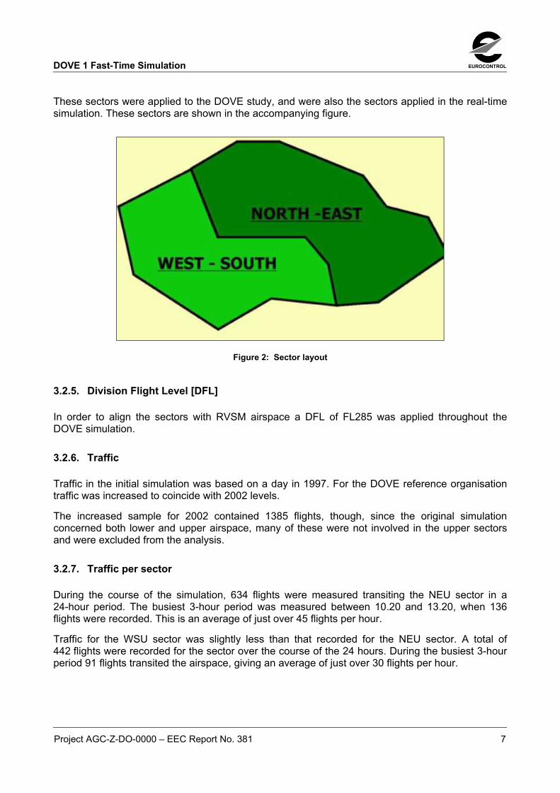
Project AGC-Z-DO-0000 � EEC Report No. 381 7
These sectors were applied to the DOVE study, and were also the sectors applied in the real-timesimulation. These sectors are shown in the accompanying figure.
Figure 2: Sector layout
3.2.5. Division Flight Level [DFL]
In order to align the sectors with RVSM airspace a DFL of FL285 was applied throughout theDOVE simulation.
3.2.6. Traffic
Traffic in the initial simulation was based on a day in 1997. For the DOVE reference organisationtraffic was increased to coincide with 2002 levels.
The increased sample for 2002 contained 1385 flights, though, since the original simulationconcerned both lower and upper airspace, many of these were not involved in the upper sectorsand were excluded from the analysis.
3.2.7. Traffic per sector
During the course of the simulation, 634 flights were measured transiting the NEU sector in a24-hour period. The busiest 3-hour period was measured between 10.20 and 13.20, when 136flights were recorded. This is an average of just over 45 flights per hour.
Traffic for the WSU sector was slightly less than that recorded for the NEU sector. A total of442 flights were recorded for the sector over the course of the 24 hours. During the busiest 3-hourperiod 91 flights transited the airspace, giving an average of just over 30 flights per hour.
EUROCONTROL DOVE 1 Fast-Time Simulation
8 Project AGC-Z-DO-0000 � EEC Report No. 381
3.3. STAGE TWO � INCORPORATING DATALINK TASKS � 2002 TRAFFIC
The second stage of the study involved taking the reference organisation, and then systematicallyapplying datalink services and applications to it.
These services and applications tested are briefly outlined in Section 8.
The datalink equipage rates applied in this series of studies were: 50%, 75% and 100% equipage.
Traffic levels for this stage of the simulation remained at 2002 levels.
3.4. STAGE THREE � INCORPORATING DATALINK TASKS � 2015 TRAFFIC
On request, the STATFOR unit of EUROCONTROL also increased the original 1997 traffic sampleto expected traffic levels for 2015. This enhanced sample was used for the second series ofstudies - stage three of the simulation.
The services and applications tested were the same set of datalink services and applicationstested in the 2002 simulation runs.
The datalink equipage rates applied in this series of studies also mirrored those used for theprevious stage: 50%, 75% and 100% equipage.
DOVE 1 Fast-Time Simulation EUROCONTROL
Project AGC-Z-DO-0000 � EEC Report No. 381 9
4. SERVICES AND APPLICATIONS
The following gives a brief introduction to the services and applications applied in the studiesduring the simulation.
• ACM ATC Communications Management
The initial applications investigated were from the ACM service. This is the service thatdeals with the routine transfer of both voice and data communications for an aircrafttransiting from sector to sector, or ATSU to ATSU.
The applications investigated included the silent transfer of the aircraft to an adjacentsector or centre by datalink, and also the silent arrival on frequency of an aircraft from anadjacent unit. The task of initiating these transfers, and also of receiving the aircraft intothe current sector, was judged to routinely fall under the remit of the Executive Controlleron the suite.
A variation, however, on these studies involved assessing the workload implications if theresponsibility for the task of transferring the aircraft to the next sector was given to thePlanning controller on the suite.
A further variation was the assessment of the workload in circumstances where thesystem automatically transferred some aircraft to the adjacent sector.
• ACL ATC Clearances and Instructions
The ACL service includes messages for all level, heading and routing instructions likely tobe given to an aircraft.
The simulator does not take into account controller free choice of a heading or level tospontaneously expedite an aircraft, or alleviate potential bottlenecks before they occur.The DOVE studies on ACL concentrated on the times when an aircraft would routinely[not involved in a conflict] have been given, for example, a new level clearance by datalinkinstead of by voice.
This is only a very limited look at this service, and further investigation would beappropriate.
• CAP Controller Access Parameters
The simulation runs involving CAP assessed the anticipated impact of the availability ofaircraft parameters downlinked to the controller.
These parameters include the aircraft heading, speed or rate of change, and were judgedto have been available to the controller whenever they accessed the datablock of anaircraft. This would normally have been when they were about to give an instruction, viathe label, to an aircraft.
• PPD Pilot Preference Downlinks
The PPD service allows for the automatic downlinking of pilot preferences to the ground.
In the definition of the PPD services, the list of preferences that can be downlinked isextensive: preferred flight level, preferred speed, preferred top of descent, minimumoperating speed and so on.

EUROCONTROL DOVE 1 Fast-Time Simulation
10 Project AGC-Z-DO-0000 � EEC Report No. 381
• FLIPCY Flight Plan Consistency
The FLIPCY service alerts the controller to discrepancies between ground-based andairborne flight plans.
However, only one route exists in the simulator for any given flight. It was thereforedecided to investigate FLIPCY from the aspect of how many transmissions the servicemight save a controller in attempting to resolve the issue of an aircraft suddenly deviatingfrom course during a flight.

DOVE 1 Fast-Time Simulation EUROCONTROL
Project AGC-Z-DO-0000 � EEC Report No. 381 11
5. RAMS CONTROLLER WORKLOAD CALCULATION
5.1. RAMS
The RAMS simulator works by analysing all events in the evolution of flights across a givenairspace, in order to detect and record all the ATC actions applicable to the flights.
Each simulation event, e.g. sector entry/exit, can trigger a number of tasks that are predefined asoccurring with that event. The model identifies these tasks as having occurred and records them.
The controller tasks are grouped into five categories:
• Flight Data Management TasksInvolves tasks associated with the updating of controller information and the performanceof computer updates.
• Co-ordination TasksRecording of co-ordinations with internal and external sectors.
• Planning or Conflict Search TasksTasks performed by controllers prior to execution of a clearance, in order to ensure thatthe clearance will be safe, or that certain conditions are being met.
• Routine R/T communications TasksThese tasks include all initial calls, transfer calls, or transmission of clearances.
• Radar TasksThis group represents the tasks associated with the provision of radar separation andmonitoring.
Each task is assigned an appropriate number of seconds for its execution and the task is assignedto one or more members of the control team to execute it.
Routinely, these task timings are provided by members of the working group, based on their day-to-day experience of the working environment and conditions being simulated. However, for theDOVE studies, since no actual ATSU was involved, task timings were arrived at in anothermanner.
The timings used for the DOVE studies were a mixture of task times used during previous fast-timesimulations, and also timings recorded in the simulation facility at Brétigny-sur-Orge. These lattertask times concerned the specific EATCHIP tasks that were assumed to occur in that type ofenvironment.
The times were established by stopwatch calculation of a controller working on the EATCHIPcontroller interface, the interface that would be used in the subsequent real-time simulations.

EUROCONTROL DOVE 1 Fast-Time Simulation
12 Project AGC-Z-DO-0000 � EEC Report No. 381
5.2. CONTROLLER PERCENTAGE LOADINGS
Assigning a control position and an execution time to each task enables RAMS to calculate boththe actual workload in minutes and the percentage loading on each working position, either overthe entire simulation period or over certain peak periods.
The loading value generally used in the interpretation of controller loadings is that obtained over athree-hour period - the 3-hour percentage loading.
The 3-hour percentage loading represents the total time spent by a working position on the tasksrecorded during the busiest 3-hour period of a simulation run. It is expressed as a percentage ofthat time.
Because it is over a reasonably long period of time, this percentage loading is used to assess thebalance of workload between sectors, and also, as in the DOVE studies, to compare results of thedifferent organisations tested.
All results presented here in this report are based on the 3-hour percentage loadings recorded.
5.2.1. Controller Percentage Loadings � Definition
To assist in the interpretation of the controller loadings, approximate terms corresponding tocertain percentage thresholds are used to describe them:
• �Severe� 3-hour loading: in excess of 50%.
• �Heavy� 3-hour loading: 40% - 49%.
These percentage levels may appear to be low. However, they do not include two essentialcomponents of a controller�s workload: thinking time and the time needed to prioritise tasks andthen to catch up on them later. These workload thresholds have evolved over many years ofevaluating controller workload through fast-time simulation and are generally regarded as arealistic description of a controller�s level of work.
Currently, RAMS identifies conflicts according to strict rules � a distance of 5.1nm between twoaircraft is considered to be full separation and requires no radar workload. In reality, a controllerwould supervise this situation until certain that no conflict would arise. This notion of the radarsupervision is not reflected in the results.
What this means is that the controller percentage loadings presented here are probablyunderstated, and a 50% loading would, in fact, be closer to 55% if the radar supervisions had beentaken into account.

DOVE 1 Fast-Time Simulation EUROCONTROL
Project AGC-Z-DO-0000 � EEC Report No. 381 13
6. DOVE TASK TIMES
The timings used for the DOVE studies were a mixture of task times used during previous fast-timesimulations, and also timings recorded in the simulation facility at Brétigny-sur-Orge.
These latter task times concerned the specific EATCHIP tasks that were assumed to occur in thesimulation environment. These times were established by stopwatch calculation of a controllerworking on the EATCHIP controller interface.
This was the interface that would be used in the subsequent real-time simulations.
6.1. TASK AND TIMINGS
DisplayThe following tables contain the general controller tasks that were assigned during the studies, thecontroller to whom they were assigned and the weighting, or length of time, associated with thetask. The time allocated to each task is expressed in seconds.
Where different tasks were introduced for particular studies, they are included in the report of theindividual study.
Generic tasksAlthough specific airspaces can generate particular controller tasks, many of the tasks specified forDOVE will remain constant from sector to sector, and airspace to airspace. The tasks detailedbelow are the ones that the working group felt would be generally applicable in a generic electronicworking environment. They are not exhaustive tasks, and, in the light of experience working withthis type of interface, controller task times may need to be amended or other controller tasks mayneed to be added for future studies.
Task groupingsFurthermore, in relation to tasks in the electronic environment and to the times allocated to them, itshould be noted that a significant difference arises when assessing controller tasks in thisenvironment compared to assessing them in an environment where paper strips are used.
In the working situation where strips are used the radar tasks and the flight data managementtasks are, more or less, distinct entities. In the electronic environment, because there are no stripsto see or mark, and information is updated on the radar display, the boundary between these twocategories of tasks becomes blurred. A single function, carried out on the radar display, canactually fulfil two or more controller tasks, in terms of the categories to which these tasks could beassigned.
For example, the physical act of transferring an aircraft � done by electronic input on the radardisplay - could be assessed as being a radar task, a flight data management task, or both at theone time.
For the purposes of the DOVE studies, tasks such as these was assessed as belonging to bothradar and flight data management categories.

EUROCONTROL DOVE 1 Fast-Time Simulation
14 Project AGC-Z-DO-0000 � EEC Report No. 381
To allocate them to the two task groups, the physical tasks were timed, and then that time was splitbetween the two categories of tasks. For the example of transferring an aircraft, a two-second task,to physically input the command, was translated to a one-second radar task and a one-secondflight data management task.
Small timesThis allocation of small task times can in itself lead to substantial difficulties within a simulation.RAMS, as used for this simulation, was not capable of dealing with increments of less than onewhole second in task times. Where task times were smaller than units of whole secondsrecalculations were done manually, after the simulation run was complete.
MonitoringIt should also be noted that within this electronic environment, and particularly within the silentdatalink environment, the Planning controller would be expected to be actively involved on thesuite and aware of what was being presented on the radar display.
It is for this reason that the planning controller was allocated monitoring tasks, for actions such asaircraft arrival on frequency, departing frequency, and general monitoring of the Tactical radartasks.
These tasks were small in nature, and in the case of a voice arrival on the frequency reflected thefact that the Planner needed to be aware of the voice communication, rather than having the taskof listening to it, and thereby repeating the Tactical controller�s workload.
Waiting timeIt is extremely important to bear in mind that the tasks associated with datalink functionality inthese DOVE simulations do not include a waiting time for completion of the task in them. Theyare only dealing with the physical act of transmitting the clearance. They also assume complete, oralmost complete, rapid compliance with an instruction.
DOVE 1 Fast-Time Simulation EUROCONTROL
Project AGC-Z-DO-0000 � EEC Report No. 381 15
6.2. TASK TABLES
6.2.1. Conflict Search Tasks
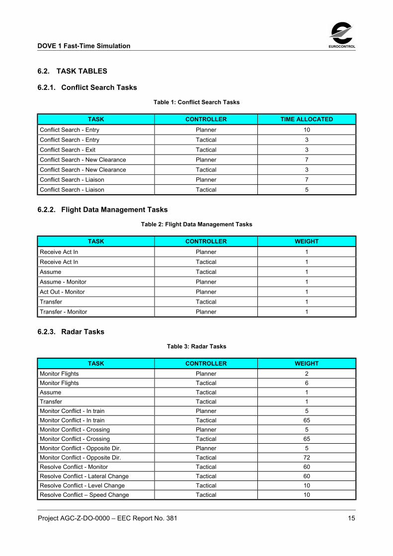
Table 1: Conflict Search Tasks
TASK CONTROLLER TIME ALLOCATEDConflict Search - Entry Planner 10Conflict Search - Entry Tactical 3Conflict Search - Exit Tactical 3Conflict Search - New Clearance Planner 7Conflict Search - New Clearance Tactical 3Conflict Search - Liaison Planner 7Conflict Search - Liaison Tactical 5
6.2.2. Flight Data Management Tasks
Table 2: Flight Data Management Tasks
TASK CONTROLLER WEIGHTReceive Act In Planner 1Receive Act In Tactical 1Assume Tactical 1Assume - Monitor Planner 1Act Out - Monitor Planner 1Transfer Tactical 1Transfer - Monitor Planner 1
6.2.3. Radar Tasks
Table 3: Radar Tasks
TASK CONTROLLER WEIGHTMonitor Flights Planner 2Monitor Flights Tactical 6Assume Tactical 1Transfer Tactical 1Monitor Conflict - In train Planner 5Monitor Conflict - In train Tactical 65Monitor Conflict - Crossing Planner 5Monitor Conflict - Crossing Tactical 65Monitor Conflict - Opposite Dir. Planner 5Monitor Conflict - Opposite Dir. Tactical 72Resolve Conflict - Monitor Tactical 60Resolve Conflict - Lateral Change Tactical 60Resolve Conflict - Level Change Tactical 10Resolve Conflict � Speed Change Tactical 10

EUROCONTROL DOVE 1 Fast-Time Simulation
16 Project AGC-Z-DO-0000 � EEC Report No. 381
6.2.4. R/T Tasks
Table 4: R/T Tasks
TASK CONTROLLER WEIGHTReceive First Call Planner 1Receive First Call Tactical 10Receive Flight Level Reached Planner 1Receive Flight Level Reached Tactical 6Transmit New Flight Level Planner 1Transmit New Flight Level Tactical 6Transmit Change of Frequency Planner 1Transmit Change of Frequency Tactical 8
6.2.5. Co-ordination Tasks
Table 5: Co-ordination Tasks
TASK CONTROLLER WEIGHTTransmit Co-ordination inter Centre Planner 4Receive Co-ordination inter Centre Planner 5

DOVE 1 Fast-Time Simulation EUROCONTROL
Project AGC-Z-DO-0000 � EEC Report No. 381 17
7. RESULTS
7.1. RESULTS INTRODUCTION
When interpreting the results presented throughout this report, account has to be taken of certainfactors and assumptions, with regard to controller working method etc., that were used throughoutthe series of studies.
HMIA controller HMI, similar to the one that was used in the DOVE real-time simulation, was assumedto be representative of those provided in future ATC systems. This is basically a mouse input HMI,with all access to labels, fields and menus being through the mouse.
Controller task times, particularly for tasks such as �Assume� and Transfer�, were based on thisHMI. If the HMI in a particular centre that intends to use datalink is significantly different from this,then controller loadings and possible benefits can also be expected to be different.
TimesThe possible benefits, and the size of the benefits, attributed to the introduction of these datalinkservices and applications are directly related to the specific task times being used in thissimulation.
If greater or lesser task times are applicable elsewhere, then it is logical to assume that thepossible benefits will be greater or smaller accordingly.
Small task timesWhilst every effort was undertaken to ensure accurate timing of tasks, when task times are as lowas 1 second the margin for error is considerable.
A half-second [0.5] variation on a 1-second task can produce a significant change in the workloadfigures.
Task splittingThe way to interpret tasks in an electronic environment, and to categorise them into groups forsimulation workload recording purposes, had not been determined before.
This model was a first attempt at placing these tasks in this type of simulation environment, andmay require further RAMS simulations to verify the validity of these placements in these taskgroups.

EUROCONTROL DOVE 1 Fast-Time Simulation
18 Project AGC-Z-DO-0000 � EEC Report No. 381
8. VOICE REPLACEMENT STUDIES � 2002 TRAFFIC
The use of datalink technology is seen as a prime enabler in the reduction of controller workload,covering a broad spectrum of controller tasks.
One of the areas where datalink is seen as being most beneficial is in the replacement of initial andfinal voice communications by datalink messages. These voice communication contacts representa considerable portion of any tactical controller�s workload, sometimes up to 40%. Other fast-timeand real-time simulations have verified this figure.
The following results report the anticipated reduction in controller workload, when these voicecontacts are replaced with datalink instructions. These datalink instructions are assumed to becompiled and sent simultaneously with radar system updates being carried out by the controllers.
The benefits are reported for scenarios in which the datalink-equipage rates were 50%, 75% and100% of the aircraft in the simulation.
The controller workload figures are presented over a 3-hour period, the busiest 3-hour periodrecorded during the 24-hour simulation of the day�s traffic. These reported loadings represent thetotal time spent by a working position on the tasks recorded during that busiest 3-hour period. Theyare recorded as percentages of that time.
All results in this first section of studies are based on 2002 levels of traffic.
None of the studies concerning this silent arrival into [Monitor] and departure of an aircraft from asector�s working environment addressed the situational awareness factors of this type ofcontrolling. The studies merely assessed the workload involved, and more detailed analysis ofsituational awareness should be covered in other studies.
Neither did these studies on Monitoring take into account other items such as a Mode-Cverification on first contact. Currently, this aircraft verification of its Mode-C read-out is arequirement. How this situation would be solved, if the requirement still existed in a predominantlydatalink environment, remains to be seen.
It was also assumed that datalink-equipped aircraft would continue to fly their current flight paths,without discrepancy, and would not need a clearance as such through the airspace, as they areprovided with by voice today. This was seen in the context that a FLIPCY type check would havebeen done prior to entry and any clearance amendments would have been processed beforehand.
8.1. REPLACEMENT OF INITIAL VOICE CONTACT - DATALINK MONITOR - 100% EQUIPAGE
8.1.1. Equipage
During this study, designed to assess the impact of the silent arrival on frequency of an aircraft, allaircraft in the simulation were assumed to be datalink-equipped.
It was anticipated that the aircraft, having transferred from the previous sector, would arrive on theselected frequency silently, sending a �Monitoring� alert to the new sector. This �Monitoring�message would alert the controller to the fact that the aircraft was indeed on the frequency andawaiting any instructions.

DOVE 1 Fast-Time Simulation EUROCONTROL
Project AGC-Z-DO-0000 � EEC Report No. 381 19
All aircraft were �Assumed� by the tactical controller. A single monitoring task was assigned to thePlanning controller, indicating that they too would become �aware� of the aircraft coming into thecontrol of the sector. This, however, replaced the two monitoring tasks previously given thePlanner in the EATCHIP environment - one for the voice arrival on frequency and one for noticingthe �Assume� by the Tactical.
8.1.2. Workload Results
The following table represents the busiest periods in terms of percentage workload, measured overperiods of three hours, for both Tactical and planning controllers in the upper sectors.
The columns in blue represent the workload measured in a standard EATCHIP environment, whilstthe columns in yellow represent the same sample measured in a datalink environment.
Percentages on the diagram are rounded up for simplicity, actual percentages are presented in theaccompanying table.
% Highest Workload - 3 HourDatalink Monitor and Assume
48
19
63
25 24
50
18
40
0
10
20
30
40
50
60
70
NEU Plan NEU Tact WSU Plan WSU Tact
EATCHIP
Datalink - 100%
Figure 3: Workload - Datalink Monitor - 100% Datalink
Sector Total Workload - EATCHIP Total Workload � Datalink 100%
NEU Planner 25.44% 24.18%NEU Tactical 62.64% 49.96%WSU Planner 19.18% 18.33%WSU Planner 48.47% 39.93%

EUROCONTROL DOVE 1 Fast-Time Simulation
20 Project AGC-Z-DO-0000 � EEC Report No. 381
8.2. REPLACEMENT OF INITIAL VOICE CONTACT � DATALINK MONITOR - 75% EQUIPAGE
8.2.1. Equipage
During this study 75% of the aircraft in the simulation were assumed to be datalink-equipped. Thismeant that 75% of the aircraft arrived silently, with a �Monitoring� alert, whilst 25% arrived into thesector with a voice contact as usual.
All aircraft, equipped or non-equipped were assumed by the tactical controller.
Again, for the datalink-equipped aircraft the Planning controllers would monitor the fact that theyhad arrived on the frequency at the same time as they monitored the radar �Assume�. In the case ofthe voice traffic arriving on frequency they had the normal second monitoring task assigned, as perthe EATCHIP baseline.
8.2.2. Workload Results
This table represents the percentage workload, measured over a period of three hours, for bothTactical and planning controllers in the upper sectors.
The columns in blue represent the workload measured in a standard EATCHIP environment, whilstthe columns in green represent the same sample measured in a datalink environment, but one inwhich only 75% of the aircraft are arriving silently into the sector with a �Monitoring� message.
Percentages on the diagram are rounded up for simplicity, actual percentages are presented in theaccompanying table.
% Highest Workload - 3 HourDatalink Monitor and Assume
25
63
19
48
24
54
19
42
0
10
20
30
40
50
60
70
NEU Plan NEU Tact WSU Plan WSU Tact
EATCHIP
Datalink - 75%
Figure 4: Workload - Datalink Monitor - 75% Datalink
Sector Total Workload - EATCHIP Total Workload � Datalink 75%
NEU Planner 25.44% 24.49%
NEU Tactical 62.64% 53.76%
WSU Planner 19.18% 18.57%
WSU Tactical 48.47% 42.43%

DOVE 1 Fast-Time Simulation EUROCONTROL
Project AGC-Z-DO-0000 � EEC Report No. 381 21
8.3. REPLACEMENT OF INITIAL VOICE CONTACT � DATALINK MONITOR - 50% EQUIPAGE
8.3.1. Equipage
During this study only 50% of the aircraft in the simulation were assumed to be datalink-equipped.This meant that 50% of the aircraft arrived silently, with a �Monitoring� message, whilst 50% of themarrived with a voice contact.
The task of �Assume� remained with the tactical controller, irrespective of datalink equipage.
In line with the previous studies the Planning controllers would monitor the fact that the datalink-equipped aircraft had arrived on frequency at the same time as they monitored the radar assume.They also monitored the voice arrivals separately.
8.3.2. Workload Results
This table represents the percentage workload, measured over a period of three hours, for bothTactical and planning controllers in the upper sectors.
The columns in blue represent the workload measured in a standard EATCHIP environment, whilstthe columns in light blue represent the same sample measured in a datalink environment, but onein which only 50% of the aircraft are arriving silently, using datalink.
Percentages on the diagram are rounded up for simplicity, actual percentages are presented in theaccompanying table.
% Highest Workload - 3 HourDatalink Monitor and Assume
48
19
63
25 25
58
45
19
0
10
20
30
40
50
60
70
NEU Plan NEU Tact WSU Plan WSU Tact
EATCHIPDatalink - 50%
Figure 5: Workload - Datalink Monitor - 50% Datalink
Sector Total Workload - EATCHIP Total Workload � Datalink 50%
NEU Planner 25.44% 24.81%
NEU Tactical 62.64% 57.57%
WSU Planner 19.18% 18.75%
WSU Tactical 48.47% 44.93%

EUROCONTROL DOVE 1 Fast-Time Simulation
22 Project AGC-Z-DO-0000 � EEC Report No. 381
8.4. REPLACEMENT OF INITIAL VOICE CONTACT � DATALINK MONITOR � RESULTS OVERVIEW
8.4.1. Overall Results
These 3 studies covered the use of the �Monitoring� message in datalink. This is the message thatwould be used by an aircraft silently arriving on a new sector�s frequency. The studies covereddatalink equipage rates from 100%, through 75% and down to 50 %.
Some factors, beyond those already identified in the general account of controller tasks, need to betaken into account when interpreting these figures.
No account of the situational awareness factors has been taken into account for these workloadfigures � they simply measure the changes in controller tasks.
No account has been taken, either, in the datalink task of the present day requirement to verify anaircraft�s Mode-C readout, or to issue it with a clearance through the airspace. For this latter part, itis assumed that an aircraft would merely continue to fly the route in the FMS, with anydiscrepancies from the expected route already sorted out by a FLIPCY check.
The size of the anticipated benefits would be directly in line with the amount of time that thecontroller is currently spending on the voice task of �Initial Contact�. In these simulations, a 10-second task was applied, to allow time for the controller to acknowledge the first contact from anaircraft, give a route clearance [or partial route clearance] and receive an acknowledgement fromthe aircraft. If that sequence were greater or less than 10 seconds then benefits from replacing itwith a �Monitoring� arrival might be expected to be lower or higher.
In mixed-equipage scenarios, the task of identifying whether an aircraft was datalink equipped ornot, and then deciding whether to use datalink or not was only given a small value [1 second]. Thisfigure is very much dependent on two factors � controller HMI, and also on the routine in acontrollers life. If controllers are presented with an HMI that allows them to easily distinguishbetween datalink and non-datalink flights, and then if they are making these decisions on a regularbasis and using datalink in a routine and natural way, that fact will be reflected by a small decisiontime. If this is not the case, then that time may need to be reviewed.
8.4.1.1. Tactical Controller NEU
Leaving aside the factors mentioned above, these studies showed the substantial potential benefitof using datalink to replace the initial voice contact with an aircraft. Based on a given voice tasktime of 10 seconds, the benefits ranged from 12.68% reduction in the Tactical workload in acomplete datalink environment, to 8.88% in a predominantly datalink environment, toapproximately a 5% reduction in the Tactical workload in a situation where 50% of the aircraft weredatalink-equipped.
These benefits in workload reduction actually equated to approximately 20%, 14% and 8%reductions when assessed as a percentage of the initial total controller workload.

DOVE 1 Fast-Time Simulation EUROCONTROL
Project AGC-Z-DO-0000 � EEC Report No. 381 23
8.4.1.2. Tactical Controller WSU
Traffic was lighter in the WSU sector, and the controller workload figures were accordingly lower.The reductions in the workload percentage for the sector, though smaller than the NEU, weregenerally in line with NEU. Controller reductions of nearly 8.34%, 5.84% and 3.34% equated toreductions ranging from 17%, to 12%, to 7% when assessed as a percentage of the initial totalcontroller workload
8.4.1.3. Planning Controllers NEU and WSU
There was no noticeable improvement shown in the workload figures for the Planning controller.This was due to the fact that all communications activity remained exclusively with the tacticalcontroller and the only changes to the Planning workload were small changes in their monitoringfunctions.

EUROCONTROL DOVE 1 Fast-Time Simulation
24 Project AGC-Z-DO-0000 � EEC Report No. 381
8.5. REPLACEMENT OF FINAL VOICE CONTACT � DATALINK VCI - 100% EQUIPAGE
8.5.1. Equipage
All aircraft in this simulation run were assumed to be datalink-equipped.During this study the task of transferring an aircraft from one sector to another was affected bydatalink � an uplinked Voice Change Instruction [VCI] replaced the task of transferring an aircraftby voice. It was expected that the task of transferring the aircraft to the next frequency by VCIhappened at the same time, and by the same action, as the tactical controller performing a radartransfer.It was also assumed that the Planning controller would monitor the fact that the aircraft had beeninstructed to leave the frequency at the same time as they monitored the radar transfer. Only onemonitor task was assigned, rather than the two that exist in the voice environment.
8.5.2. Workload Results
This table represents the busiest periods in terms of percentage workload, measured over periodsof three hours, for both Tactical and planning controllers in the upper sectors.The columns in blue represent the workload measured in a standard EATCHIP environment, whilstthe columns in yellow represent the same sample measured in a datalink environment.Percentages on the diagram are rounded up for simplicity, actual percentages are presented in theaccompanying table.
% Highest Workload - 3 HourDatalink VCI and Transfer
25
63
19
48
42
18
53
24
0
10
20
30
40
50
60
70
NEU Plan NEU Tact WSU Plan WSU Tact
EATCHIP
Datalink - 100%
Figure 6: Workload - Datalink VCI Transfer - 100% Datalink
Sector Total Workload - EATCHIP Total Workload � Datalink 100%
NEU Planner 25.44% 24.18%NEU Tactical 62.64% 52.57%WSU Planner 19.18% 18.33%WSU Planner 48.47% 41.82%

DOVE 1 Fast-Time Simulation EUROCONTROL
Project AGC-Z-DO-0000 � EEC Report No. 381 25
8.6. REPLACEMENT OF FINAL VOICE CONTACT � DATALINK VCI - 75% EQUIPAGE
8.6.1. Equipage
During this study 75% of the aircraft in the simulation were assumed to be datalink-equipped. Asfor the previous study, it was anticipated that the task of transferring the aircraft to the nextfrequency happened at the same time, and by the same action, as the tactical controller performinga radar transfer to the next sector.
All aircraft, equipped or non-equipped were assumed to be transferred by the tactical controller.
Again, the Planning controllers would monitor the fact that the datalink-equipped aircraft had beeninstructed to leave the frequency at the same time as they monitored the radar transfer. In the caseof voice transfer traffic they were assumed to have the normal second monitoring task associatedwith a voice transfer.
8.6.2. Workload Results
This table represents the percentage workload, measured over a period of three hours, for bothTactical and planning controllers in the upper sectors.
The columns in blue represent the workload measured in a standard EATCHIP environment, whilstthe columns in green represent the same sample measured in a datalink environment, but one inwhich only 75% of the aircraft are transferred using datalink.
Percentages on the diagram are rounded up for simplicity, actual percentages are presented in theaccompanying table.
% Highest Workload - 3 HourDatalink VCI and Transfer
48
19
63
25
44
19
56
24
0
10
20
30
40
50
60
70
NEU Plan NEU Tact WSU Plan WSU Tact
EATCHIP
Datalink - 75%
Figure 7: Workload - Datalink VCI and Transfer - 75% Datalink
Sector Total Workload - EATCHIP Total Workload � Datalink 75%
NEU Planner 25.44% 24.49%NEU Tactical 62.64% 56.34%WSU Planner 19.18% 18.59%WSU Tactical 48.47% 44.24%
EUROCONTROL DOVE 1 Fast-Time Simulation
26 Project AGC-Z-DO-0000 � EEC Report No. 381
8.7. REPLACEMENT OF FINAL VOICE CONTACT � DATALINK VCI - 50% EQUIPAGE
8.7.1. Equipage
During this study only 50% of the aircraft in the simulation were assumed to be datalink-equipped.Again, it was anticipated that the task of transferring the aircraft to the next frequency happened atthe same time, and by the same action, as the tactical controller performing a radar transfer to thenext sector.
The task of transfer remained exclusively with the tactical controller.
In line with the previous studies the Planning controllers would monitor the fact that the datalink-equipped aircraft had been instructed to leave the frequency at the same time as they monitoredthe radar transfer. Also in line with previous studies, in the event of a voice transfer a secondmonitoring task was assigned to the Planners.
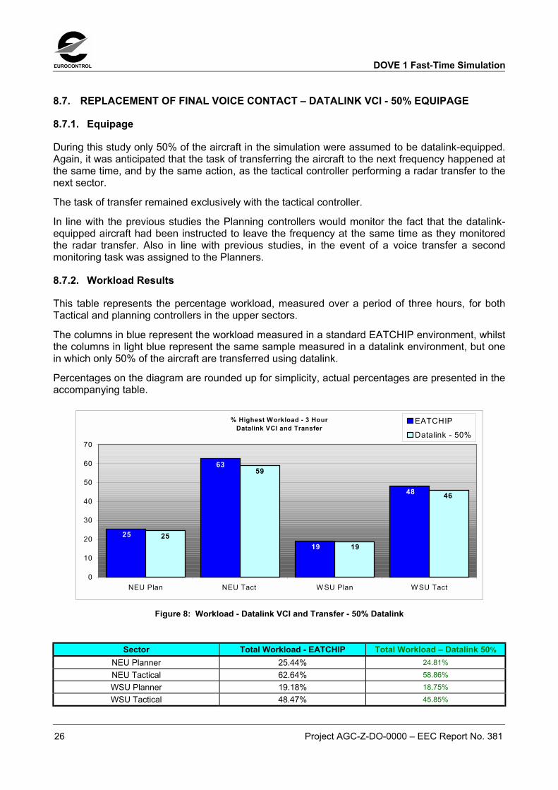
8.7.2. Workload Results
This table represents the percentage workload, measured over a period of three hours, for bothTactical and planning controllers in the upper sectors.
The columns in blue represent the workload measured in a standard EATCHIP environment, whilstthe columns in light blue represent the same sample measured in a datalink environment, but onein which only 50% of the aircraft are transferred using datalink.
Percentages on the diagram are rounded up for simplicity, actual percentages are presented in theaccompanying table.
% Highest Workload - 3 HourDatalink VCI and Transfer
25
63
19
48
19
46
59
25
0
10
20
30
40
50
60
70
NEU Plan NEU Tact W SU Plan W SU Tact
EATCHIP
Datalink - 50%
Figure 8: Workload - Datalink VCI and Transfer - 50% Datalink
Sector Total Workload - EATCHIP Total Workload � Datalink 50%NEU Planner 25.44% 24.81%NEU Tactical 62.64% 58.86%WSU Planner 19.18% 18.75%WSU Tactical 48.47% 45.85%

DOVE 1 Fast-Time Simulation EUROCONTROL
Project AGC-Z-DO-0000 � EEC Report No. 381 27
8.8. REPLACEMENT OF FINAL VOICE CONTACT � DATALINK VCI � RESULTS OVERVIEW
8.8.1. Overall Results
These initial 3 studies covered the use of datalink in transferring aircraft to an adjacent sector, incircumstances that ranged from ideal [100% equipage] to those that may be considered the mostproblematic [50% equipage].
Factors already highlighted in the previous reports need to be remembered here again, whenassessing these figures.
The size of the anticipated benefits would be directly in line with the amount of time that thecontroller is currently spending on the voice task of �Final Contact�. In these simulations, an 8-second task was applied, to allow time for the controller to give the appropriate frequency andreceive a full acknowledgement from the aircraft.
If that sequence were greater or less than 8 seconds then benefits from replacing it with a �VCI�might be expected to be lower or higher.
Also, the benefit of datalink in reducing frequency errors and reducing the amount of controller orpilot verification of frequencies, particularly in the light of 8.33 frequency use, is not taken intoaccount here. There is only one transmission allowed for in changing frequency.
8.8.1.1. Tactical Controller NEU
In general, these studies showed the substantial potential benefit of using datalink to replace oneof the most routine tasks in a controller�s work, that of transferring an aircraft to an adjacent sector.Based on a given task time of 8 seconds to transfer the aircraft [transfer instruction plus readback,the benefits ranged from 10% reduction in the Tactical workload in a complete datalinkenvironment, to 6.3% in a predominantly datalink environment, to approximately a 3.75% reductionin the Tactical workload in a situation where 50% of the aircraft were datalink-equipped.
These benefits in workload reduction actually equated to approximately 16%, 10% and 6%reductions when assessed as a percentage of the initial total controller workload.
8.8.1.2. Tactical Controller WSU
Traffic was lighter in the WSU sector, and the controller workload figures were accordingly lower.The reductions in the workload percentage for the sector, though smaller than the NEU, weregenerally in line with NEU.
Controller reductions of nearly 6.65%, 4.23% and 2.62% equated to reductions ranging from 14%,to 9%, to 5% when assessed as a percentage of the initial total controller workload.
8.8.1.3. Planning Controllers NEU and WSU
There was a very small improvement shown in the workload figures for the Planning controller, a1.26% decrease for the NEU sector, and less than 1% for the WSU sector. This was due to the factthat all communications activity remained exclusively with the tactical controller and the only taskeliminated from the Planning controller was a small one of monitoring the voice transmission tochange frequency.

EUROCONTROL DOVE 1 Fast-Time Simulation
28 Project AGC-Z-DO-0000 � EEC Report No. 381
8.9. REPLACEMENT OF INITIAL AND FINAL VOICE CONTACT � COMBINED OVERVIEW
8.9.1. Overall Results
As would be expected, when the results for replacing the initial voice contact and the final voicecontact are added together they produce very significant decreases in controller workload figures.A series of simulation runs was conducted to verify this, and the results are presented here in thefollowing tables.
% Highest Workload - 3 HourData link Assume InData link Transfer out
48
19
63
25 23
40
17
33
0
10
20
30
40
50
60
70
NEU Plan NEU Tact WSU Plan WSU Tact
Eatchip
Data Link - 100%
Figure 9: Workload - Datalink Monitor and VCI Combined - 100% Datalink
% Highest Workload - 3 HourDatalink Monitor and AssumeDatalink VCI and Transfer
25
63
19
48
24
47
18
38
0
10
20
30
40
50
60
70
NEU Plan NEU Tact WSU Plan WSU Tact
Eatchip
Data Link - 75%
Figure 10: Workload - Datalink Monitor and VCI Combined - 75% Datalink
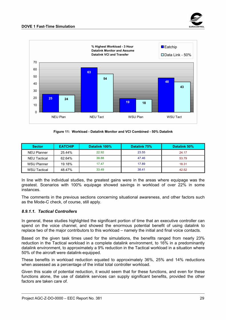
DOVE 1 Fast-Time Simulation EUROCONTROL
Project AGC-Z-DO-0000 � EEC Report No. 381 29
% Highest Workload - 3 HourDatalink Monitor and AssumeDatalink VCI and Transfer
48
19
63
25 24
54
43
18
0
10
20
30
40
50
60
70
NEU Plan NEU Tact WSU Plan WSU Tact
Eatchip
Data Link - 50%
Figure 11: Workload - Datalink Monitor and VCI Combined - 50% Datalink
Sector EATCHIP Datalink 100% Datalink 75% Datalink 50%NEU Planner 25.44% 22.92 23.55 24.17
NEU Tactical 62.64% 39.88 47.46 53.79
WSU Planner 19.18% 17.47 17.89 18.31
WSU Tactical 48.47% 33.49 38.41 42.52
In line with the individual studies, the greatest gains were in the areas where equipage was thegreatest. Scenarios with 100% equipage showed savings in workload of over 22% in someinstances.
The comments in the previous sections concerning situational awareness, and other factors suchas the Mode-C check, of course, still apply.
8.9.1.1. Tactical Controllers
In general, these studies highlighted the significant portion of time that an executive controller canspend on the voice channel, and showed the enormous potential benefit of using datalink toreplace two of the major contributors to this workload � namely the initial and final voice contacts.
Based on the given task times used for the simulations, the benefits ranged from nearly 23%reduction in the Tactical workload in a complete datalink environment, to 16% in a predominantlydatalink environment, to approximately a 9% reduction in the Tactical workload in a situation where50% of the aircraft were datalink-equipped.These benefits in workload reduction equated to approximately 36%, 25% and 14% reductionswhen assessed as a percentage of the initial total controller workload.Given this scale of potential reduction, it would seem that for these functions, and even for thesefunctions alone, the use of datalink services can supply significant benefits, provided the otherfactors are taken care of.
EUROCONTROL DOVE 1 Fast-Time Simulation
30 Project AGC-Z-DO-0000 � EEC Report No. 381
8.9.1.2. Planning Controllers
There was a very small improvement shown in the workload figures for the Planning controllers �up to 2.5%. However, this is viewed in the context that the Planners are already operating at a verycomfortable level, and the requirement to reduce workload is not especially targeted at them.
This was mainly due to the fact that the monitoring of the radar action and the monitoring of theflight arriving or leaving the sector were considered to have occurred at the same time. This isdifferent from the baseline scenarios, where the voice contact on frequency is a distinct entity initself, apart from the associated radar actions.

DOVE 1 Fast-Time Simulation EUROCONTROL
Project AGC-Z-DO-0000 � EEC Report No. 381 31
9. TASK REDISTRIBUTION STUDIES � 2002 TRAFFIC
9.1. DATALINK TRANSFER - PLANNING CONTROLLER
9.1.1. General
The transfer of some executive tasks, from the tactical controller to the Planning controller on thesuite, will achieve some of the major benefits envisaged in a datalink environment. It will help evenout the workload, by providing better distribution of work. The specific tasks to be delegated willvary from ATSU to ATSU, but it is felt that the transfer of aircraft will be one of the tasks that mightprove suitable for this delegation.
Potential workload gains for this task were investigated in a specific study, where the Planningcontroller transferred a significant percentage of the aircraft in the simulation.
9.1.2. Equipage
For this specific study, 75% of the aircraft in the simulation were again assumed to be datalink-equipped. However, workload was measured this time against tasks in which the Planningcontroller transferred all of these datalink-equipped aircraft, whilst the remainder of the aircraft[25%] were voice transferred by the Tactical controller.
To illustrate the change in task responsibility, a radar task of transferring the datalink aircraft wasgiven to the Planning controller. A second new task was also introduced for the Planningcontrollers, that of a conflict search task as the aircraft was approaching the boundary. This 3-second task was intended to show that the Planner had identified that the aircraft was datalink-equipped, was achieving its exit conditions, and so was theirs to transfer.
In line with the general behaviour required in this type of system, both controllers were assumed tomonitor the radar tasks of the other. However, they were considered to have monitored the factthat the aircraft had been instructed to leave the frequency at the same time that they monitoredthe radar transfer performed by the other controller.
9.1.3. Workload Results
The following table represents the percentage workload, measured over three hours, for bothTactical and planning controllers in the upper sectors.
The columns in blue represent the workload measured in a standard EATCHIP environment, whilstthe columns in burgundy represent the same sample measured in a datalink environment, but onein which 75% of the aircraft are transferred by the Planning controller, using datalink.
The columns in green represent the results from the previous 75% study, where the tacticalcontroller transferred the aircraft, and are included for comparison.
Percentages on the diagram are rounded up for simplicity, actual percentages are presented in theaccompanying table.
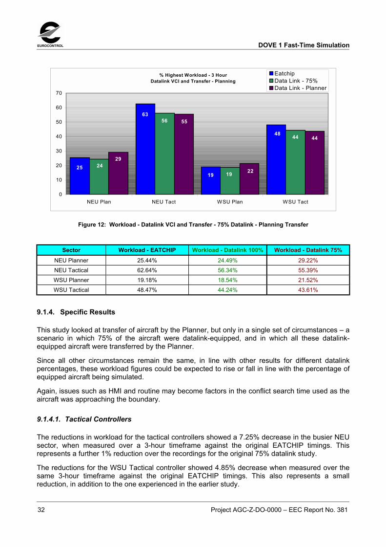
EUROCONTROL DOVE 1 Fast-Time Simulation
32 Project AGC-Z-DO-0000 � EEC Report No. 381
% Highest Workload - 3 HourDatalink VCI and Transfer - Planning
25
63
19
48
24
56
19
44
29
55
22
44
0
10
20
30
40
50
60
70
NEU Plan NEU Tact WSU Plan WSU Tact
EatchipData Link - 75%Data Link - Planner
Figure 12: Workload - Datalink VCI and Transfer - 75% Datalink - Planning Transfer
Sector Workload - EATCHIP Workload - Datalink 100% Workload - Datalink 75%NEU Planner 25.44% 24.49% 29.22%NEU Tactical 62.64% 56.34% 55.39%WSU Planner 19.18% 18.54% 21.52%WSU Tactical 48.47% 44.24% 43.61%
9.1.4. Specific Results
This study looked at transfer of aircraft by the Planner, but only in a single set of circumstances � ascenario in which 75% of the aircraft were datalink-equipped, and in which all these datalink-equipped aircraft were transferred by the Planner.
Since all other circumstances remain the same, in line with other results for different datalinkpercentages, these workload figures could be expected to rise or fall in line with the percentage ofequipped aircraft being simulated.
Again, issues such as HMI and routine may become factors in the conflict search time used as theaircraft was approaching the boundary.
9.1.4.1. Tactical Controllers
The reductions in workload for the tactical controllers showed a 7.25% decrease in the busier NEUsector, when measured over a 3-hour timeframe against the original EATCHIP timings. Thisrepresents a further 1% reduction over the recordings for the original 75% datalink study.
The reductions for the WSU Tactical controller showed 4.85% decrease when measured over thesame 3-hour timeframe against the original EATCHIP timings. This also represents a smallreduction, in addition to the one experienced in the earlier study.

DOVE 1 Fast-Time Simulation EUROCONTROL
Project AGC-Z-DO-0000 � EEC Report No. 381 33
These further decreases in workload, at first sight, would seem to be smaller than what one mightexpect. However, that can be explained by the fact that Tactical, whilst no longer doing thephysical act of transferring the aircraft, must maintain awareness of what is going on andawareness of which aircraft the Planner is likely to transfer. To do this it was assumed that theTactical would continue the task of validating the exit conditions on all aircraft. The task ofmonitoring each Planning transfer is also now recorded for the tactical controller, replacing theirphysical action of doing the transfer.
9.1.4.2. Planning Controllers
There were, as expected, increases in the workload noticed for the Planning controllers, 4.22% forthe NEU and 2.34% for the WSU. These corresponded to the increased tasks given to them.
It should be noted that the Planning controllers during this scenario are operating at quite acomfortable workload figure and some spare capacity is clearly there to be tapped. However, theamount of that spare capacity for the Planning controller will only become clearer as other morePlanning-orientated functions, such as FLIPCY or MTCD , are accounted for in their work.
9.2. DATALINK TRANSFER � SYSTEM TRANSFER OF AIRCRAFT
9.2.1. General
As was previously mentioned, the transfer of some executive tasks, from the tactical controller tothe Planning controller on the suite, will achieve some of the major benefits envisaged in a datalinkenvironment.
Datalink, however, also gives the opportunity for some tasks to be transferred not only from thecontroller to controller, but also from the controllers to the ground system itself.
The specific tasks to be delegated, and automated by the system, will vary from place to place andwill depend on the working environment and local agreed procedures. For the purposes of theDOVE studies, the automatic transfer of aircraft was looked at, again, purely in terms of task time,and without going into detail on the other factors such as situational awareness.
The automatic proposal to transfer an aircraft would be based on system recognition of variousdetails of the flight � time to run to the boundary, a comparison of flight conditions with required exitconditions, and most probably a crosscheck with other systems such as STCA and MTCD. It wouldbe only in the cases where the flight has met its exit conditions by a predetermined point that thesystem would be allowed to propose a transfer.
Potential workload gains for this task were investigated in a special study, where the systemperformed an automatic transfer of aircraft as they approached the boundary.
In looking at the automation of any tasks by the system, it is imperative that controller over-ride andpre-acceptance of the task before implementation by the system will be in effect. It is envisagedthat the system would propose transfer in a predetermined timeframe [30 seconds?], therebyallowing controller assessment veto if required.
This proposal by the system would be used as a prompt to the controller to carry out their own exitcondition check before agreeing to the transfer.
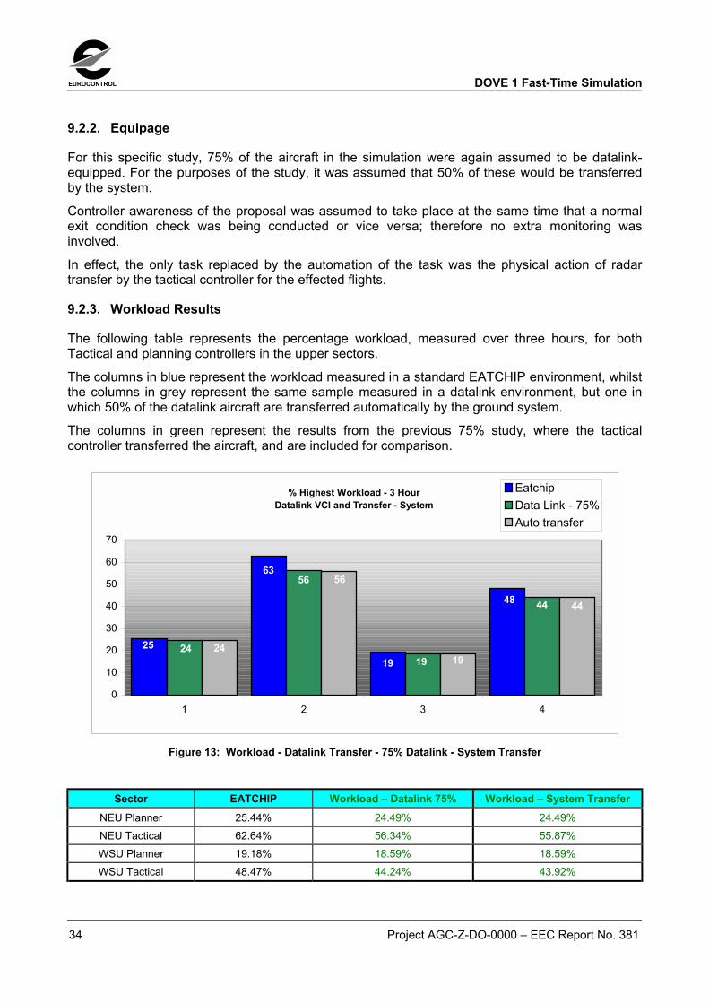
EUROCONTROL DOVE 1 Fast-Time Simulation
34 Project AGC-Z-DO-0000 � EEC Report No. 381
9.2.2. Equipage
For this specific study, 75% of the aircraft in the simulation were again assumed to be datalink-equipped. For the purposes of the study, it was assumed that 50% of these would be transferredby the system.
Controller awareness of the proposal was assumed to take place at the same time that a normalexit condition check was being conducted or vice versa; therefore no extra monitoring wasinvolved.
In effect, the only task replaced by the automation of the task was the physical action of radartransfer by the tactical controller for the effected flights.
9.2.3. Workload Results
The following table represents the percentage workload, measured over three hours, for bothTactical and planning controllers in the upper sectors.
The columns in blue represent the workload measured in a standard EATCHIP environment, whilstthe columns in grey represent the same sample measured in a datalink environment, but one inwhich 50% of the datalink aircraft are transferred automatically by the ground system.
The columns in green represent the results from the previous 75% study, where the tacticalcontroller transferred the aircraft, and are included for comparison.
% Highest Workload - 3 HourDatalink VCI and Transfer - System
48
19
63
25
44
19
56
24 24
56
19
44
0
10
20
30
40
50
60
70
1 2 3 4
EatchipData Link - 75%Auto transfer
Figure 13: Workload - Datalink Transfer - 75% Datalink - System Transfer
Sector EATCHIP Workload � Datalink 75% Workload � System TransferNEU Planner 25.44% 24.49% 24.49%NEU Tactical 62.64% 56.34% 55.87%WSU Planner 19.18% 18.59% 18.59%WSU Tactical 48.47% 44.24% 43.92%

DOVE 1 Fast-Time Simulation EUROCONTROL
Project AGC-Z-DO-0000 � EEC Report No. 381 35
9.2.4. Specific Results
As can be seen from the figures, this automation of the transfer task produced only a very smallfurther gain for the tactical controllers.
This small gain resulted from the fact that although the system did the transfer task, all other tasksassociated with a transfer, such as monitoring by the controllers, or controllers conducting aconflict search prior to exit, still remained.
It is thought that this type of automation of tasks will require further study in the future.
EUROCONTROL DOVE 1 Fast-Time Simulation
36 Project AGC-Z-DO-0000 � EEC Report No. 381
10. CAP � CONTROLLER ACCESS PARAMETERS � 2002 TRAFFIC
10.1. GENERAL
Controller Access Parameters [CAP] are a set of aircraft parameters automatically downlinked,without pilot intervention, to the ground and available for display to the controllers.
The parameters include aircraft heading, speed and rate of change, either climbing or descending.
As with any new technology or service, the way the service will be used is a matter of conjecture.For CAP, this will depend on several factors, including the refresh rate of the informationpresented, and the presentation and interface available to the controller.
For the purposes of the DOVE 1 fast-time studies, it was determined that the rate of informationwould be consistent with the radar update, which meant it would be current and accurate whenaccessed. The display was assumed to be similar to that on the EATCHIP interface that would beused in the real-time simulations. This meant that the CAP values were not necessarily presentedat all times, but rather when the controller accessed an aircraft�s label.
As mentioned before the way that a new service is used is open to conjecture. Until �live�experience is gained the amount of times that a service might be used is also open to conjecture.
Whilst the controllers, in their �scan� of their situation displays, might take note of CAP values asthey passed over labels and updated their information, it was felt that in reality the main benefits ofCAP lay elsewhere.
It is anticipated that one of the main benefits of the display of CAP information would be in actingas an assurance for controllers of an aircraft�s trajectory. This way, display of values couldeliminate the need for a questioning call on the R/T to an aircraft about, say, its current heading,prior to issuing a new one.
Another benefit would be in the assurance to the controller of aircraft compliance with ATCinstructions. It is assumed that controllers would access CAP values when they wished to confirm[without resorting to voice] aircraft compliance with an instruction, particularly during the resolutionof a conflict.
10.1.1. Method of application
Since new headings, levels or other changes to aircraft trajectories are usually only applied inRAMS as a result of a controller need to alter a profile in response to a conflict, in order to gaugethe potential workload reduction brought about by the availability to the controller of CAPs, it wasassumed that CAP would only be used when conflicts or radar interventions were registered.
In an attempt to quantify the amount of benefit the following methodology was used. When anaircraft is involved in a conflict in RAMS a certain task time is allocated to dealing with the conflict.This time is comprised of separate individual times allocated to specific actions dealing with theconflict, including surveillance.
If the controller has CAP values presented during a conflict, it could be assumed that thesurveillance portion of a conflict task time would be shorter than normal. Accordingly, thesurveillance part of the conflict and resolution time in determining a new heading, and thenmaintaining overall surveillance of the conflict was shortened from 10 seconds to 5 seconds foreach one.

DOVE 1 Fast-Time Simulation EUROCONTROL
Project AGC-Z-DO-0000 � EEC Report No. 381 37
10.2. RESULTS
By using the assurance given by the CAP values to lessen surveillance time in conflicts thecontrollers could expect to gain a workload reduction of approximately 1.5% in radar tasks.
The benefit of having the values available at other times, and using them in the course of generalmonitoring, is not quantifiable in this type of simulation.
10.2.1. Workload Results
The following table represents the percentage workload, measured over three hours, for bothTactical and planning controllers in the upper sectors.
The columns in blue represent the workload measured in a standard EATCHIP environment, whilstthe columns in yellow represent the same sample measured in a datalink environment, where CAPwas assumed to be used in conflict resolution.
Controller Access Parameters
25
63
19
48
25
61
19
47
0
10
20
30
40
50
60
70
NEU Plan NEU Tact WSU Plan WSU Tact
EatchipCAP
Figure 14: Workload - CAP � Controller Access Parameters
Sector EATCHIP CAPNEU Planner 25.44% 25.44%NEU Tactical 62.64% 61.29%WSU Planner 19.18% 19.18%WSU Tactical 48.27% 47.11%

EUROCONTROL DOVE 1 Fast-Time Simulation
38 Project AGC-Z-DO-0000 � EEC Report No. 381
11. PPD � PILOT PREFERENCE DOWNLINKS � 2002 TRAFFIC
11.1. GENERAL
Pilot Preference Downlinks [PPD] are aircraft downlinks to the ground, providing information to thecontrollers, amongst other things, on a pilot�s preference for a level or speed different to the onethat they are currently using, or different to their filed flight plan.
In common with CAP, it was difficult to define how this service would be used, how often it wouldbe used and how the information and requests would be presented to the controllers.
To fix a value for it, and to test the value of PPD to the Tactical controller, it was determined that upto 10% of the aircraft transiting an airspace might have occasion to use PPD. This figure waschosen to embrace both flights that might show a preference for a new level, and also to representoccasions when a controller might have asked for confirmation of a level being acceptable prior toissuing one to resolve a conflict.
It was estimated that this might occur in approximately 10 -15% of conflicts.
In terms of the Planning controller the value of PPD is in the provision of preferences before theaircraft enters the sector. This information could then be used in determining the most suitableoption for conflict resolution.
However, since this is simply further information for the Planner rather than a change in work ortasks, it was felt that the provision of PPD would have no material effect on workload for thePlanner.
11.2. RESULTS
Because of the small number of aircraft thus requiring or requesting level changes by PPD, and thelimited amount of conflicts occurring in the simulation where PPD might be referenced the savingswere almost negligible � not even 1% of workload for the Tactical controller.

DOVE 1 Fast-Time Simulation EUROCONTROL
Project AGC-Z-DO-0000 � EEC Report No. 381 39
12. ACL � ATC CLEARANCES AND INSTRUCTIONS � 2002 TRAFFIC
12.1. GENERAL
Datalink CPDLC is intended to be used in a strategic fashion, for routine messages, where time isnot a critical factor.
Because of the timeframe of message delivery, it is not presently considered to be suitable for usein tactical situations.
When looking at the ACL services for the DOVE simulation, the study concentrated mainly onissuing of a level or route clearance in a non-critical situation. Behaviour for other aspects of ACL,such as SSR uplink, would be expected to be the same.
12.2. RESULTS
For this study, it was determined that the average time of transmission for a level clearance, orsimple route instruction to be given to a flight, was 7 seconds. This covered the clearances givenby the controller and the read-back by the pilot, and also simultaneous input on the radar display.
It was also assumed that the average time to give a similar clearance by datalink was in the regionof 3 seconds � 1 second to decide whether the clearance was strategic in nature [and therebydetermining the which communications medium to use] and then 2 seconds to carry out the inputon the HMI.
Savings accounted for by the ACL service will invariably depend on the amount of these non-time-critical clearances that a controller would give in the course of their work.
Given the task times mentioned above, the following results show the possible savings in workloadfor various rates of clearances. In order to keep them in line with the rest of the workload figurescontained in the report they have been presented in terms of controller workload over 3 hours.
12.2.1. Workload Results
The following table represents the percentage workload, measured over three hours, of severalinstances of the issuance of ACL clearances.
The columns in blue represent the workload measured where these clearances are given by voice,whilst the columns in yellow represent the workload for these tasks done by datalink environment.Figures are presented for various rates of issuance of the clearances.

EUROCONTROL DOVE 1 Fast-Time Simulation
40 Project AGC-Z-DO-0000 � EEC Report No. 381
ACL - ATC Clearances
11.7
5.8
3.82.3
5
2.5 21.3
0%
4%
8%
12%
Every minute Every 2 mins. Every 3 mins. Every 5 mins.Minutes each message
Voice ClearancesDatalink ACL
Figure 15: Workload - ACL � ATC Clearances
1 message per 1 min 1 message per 2 mins. 1 message per 3 mins. 1 message per 5 mins.Voice 11.66% 5.80% 3.80% 2.33%ACL 5% 2.50% 2% 1.30%
12.2.2. Specific Results
As can be seen from the figures, this replacement of voice by datalink in this context producedresults that varied considerably, depending on usage. They all roughly equate, however, to ahalving of the workload in each case.
These gains would have to be assessed against the amount of this type of clearance that would beissued in any airspace.
DOVE 1 Fast-Time Simulation EUROCONTROL
Project AGC-Z-DO-0000 � EEC Report No. 381 41
13. FLIPCY - FLIGHT PLAN CONSISTENCY CHECK � 2002 TRAFFIC
13.1. GENERAL
After an aircraft operator has filed a flight plan, details of that flight plan are disseminated to allATSUs along the route of the flight. They are also loaded into the FMS in the cockpit of the aircraft.On occasions, the information held in these two separate systems can differ. This can lead toflights, following their FMS route, deviating unexpectedly from the route the controller believed theflight would be taking, the FDPS route. The FLIPCY service is introduced to address theseproblems.
A FLIPCY check would be done on an aircraft prior to entering the area of responsibility of anATSU. It would be conducted by the first sector in the ATSU. For the check the ground systemwould request a downlink of the aircraft route relevant to the ATSU, compare it to the details storedon the ground, and issue an alert if there was a discrepancy between the two.
The problem of aircraft deviation is more acute in some airspace than in others. Estimates varyfrom less than 5% of aircraft deviating, to instances quoted by ANSPs of 50% deviation. For thepurposes of the DOVE studies, a figure of 20% was tested.
13.1.1. Method
The ground system would automatically ask for the FMS portion of the route applicable to theATSU, compare it to the route held in the FDPS and then alert the controller if a discrepancy wasfound. The responsibility for the FLIPCY check would lie with the Planning controller.
The HMI that was assumed for this feature was one whereby a FLIPCY warning was presented tothe controller in the form of a message on the aircraft datablock. The controller, on accessing thewarning, was presented with a graphical display of the two routes stored. The controller could theneither accept the FMS route of the aircraft, which updated the ground system with the FMS route,or reject the FMS route.
If the FMS route was rejected a route clearance was prepared to be automatically uplinked to theaircraft after it came under control of the sector. No further action was required by the controller.
A FLIPCY check was determined to take approximately 5 seconds. This was 1 second torecognise the warning, 3 seconds to activate the routes and decide the more appropriate route,and then 1 second to perform the required HMI action.
This would replace an action that could take up 15 seconds of a Tactical controller�s time � thetime it was estimated that a controller would need to notice, then query a deviation, and then issuean instruction to an aircraft in order to rectify the situation.
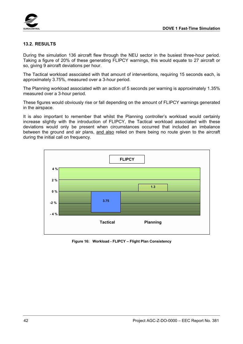
EUROCONTROL DOVE 1 Fast-Time Simulation
42 Project AGC-Z-DO-0000 � EEC Report No. 381
13.2. RESULTS
During the simulation 136 aircraft flew through the NEU sector in the busiest three-hour period.Taking a figure of 20% of these generating FLIPCY warnings, this would equate to 27 aircraft orso, giving 9 aircraft deviations per hour.
The Tactical workload associated with that amount of interventions, requiring 15 seconds each, isapproximately 3.75%, measured over a 3-hour period.
The Planning workload associated with an action of 5 seconds per warning is approximately 1.35%measured over a 3-hour period.
These figures would obviously rise or fall depending on the amount of FLIPCY warnings generatedin the airspace.
It is also important to remember that whilst the Planning controller�s workload would certainlyincrease slightly with the introduction of FLIPCY, the Tactical workload associated with thesedeviations would only be present when circumstances occurred that included an imbalancebetween the ground and air plans, and also relied on there being no route given to the aircraftduring the initial call on frequency.
Figure 16: Workload - FLIPCY � Flight Plan Consistency
4 %
2 %
0 %
-2 %
- 4 %
Tactical Planning
3.75
1.3
FLIPCY
DOVE 1 Fast-Time Simulation EUROCONTROL
Project AGC-Z-DO-0000 � EEC Report No. 381 43
14. RESULTS OVERVIEW � 2002 TRAFFIC
14.1. RESULTS
As reported earlier, the greatest benefits from datalink would appear to be in those areas wheredatalink replaces the long but necessary voice communications between controllers and pilots
In general, benefits for the non-communications aspects of datalink services � CAP, PPD and ACL- were certainly not as high as those potential benefits for communications services. This, however,is not unexpected, for several reasons:-
The first reason is that a considerable percentage of a controller�s workload is occupied by voicecommunications tasks. In these studies, voice communications workload for the tactical controllerwas almost at the same level as radar workload, with less than a 1% difference between them. Itaccounted for approximately 40% of the tactical controllers overall work. This trend in controllertasks is repeatedly seen across simulations, both fast time and real-time.
In different circumstances, in scenarios where traffic flow is even more stable, the voice taskscould even overtake the radar tasks as the main contributor to the controller�s workload. This isbecause, even though radar tasks may go down in a stable traffic environment, there is still therequirement to say at least �hello� and �goodbye� to each aircraft.
The second reason that the results present like this relates to the way that the non-ACM servicesaffect a controller�s normal routine. Services such as CAP and PPD are generally designed toprovide information to the controller in reaching decisions, and they are not intended as directreplacements for routine tasks in the way that the voice communications services are. They maysave some controller tasks, as simulated here, but that would not seem to be their primaryfunction.
Added to this is the fact that datalink use, at least for the moment, is intended to be strategic. In abusy ATC environment, involving a lot of traffic in evolution [climbing or descending], most ATCclearances would still be expected to be done by voice. Both these factors go a long way toexplaining the limited impact of the non-ACM services.
Having said that, ANY reduction in a controller�s workload, particularly in a workload that is ratedas being �heavy� or �severe� is to be welcomed, whichever service provides it.
The results for FLIPCY also fall into a different category from the results for voice tasks.Theoretically, if a controller gives a clearance to an aircraft on entering the ATSU there should bevery few, if any, occurrences of aircraft deviation. Therefore, the benefits for FLIPCY, calculatedagainst the time a controller might need to spend in resolving a deviation, would only be mostapparent if no initial clearance was given to an aircraft in the first place.

EUROCONTROL DOVE 1 Fast-Time Simulation
44 Project AGC-Z-DO-0000 � EEC Report No. 381
15. VOICE REPLACEMENT STUDIES � 2015 TRAFFIC
General
Initially, the intention of the DOVE 1 fast-time simulation was to investigate the potential benefitsbrought about by this particular set of datalink services, in the time frame in which they wereintended to be in use. That is why the year 2015 was chosen as a target year.
In fact, it was the original intention of the simulation team that traffic for 2015 would be tested first,with further tests carried out on earlier years if the opportunity arose.
However, even starting with a relatively moderate level of traffic, increasing it to 2015 levelsbrought about both a degree of uncertainty as to whether that level of traffic would be relevant atthat time, and also brought about traffic workload that would be unsustainable for a controller usingcurrent tasks and equipment.
When workload figures for the sectors were generated with 2015 levels of traffic, it soon becameapparent exactly how unsustainable they were. The Tactical controller for the NEU sector recordeda workload level of approximately 108%. This is unrealistic work for any controller, and means thatthe controller is fully occupied for 194 minutes in a 180-minute period.
That is why the emphasis of the study was primarily directed at 2002 traffic, and the detail wasfocussed on the benefits that the datalink services could produce, set against a realisticallymeasurable base.
The studies conducted for 2015 traffic must be seen in the context of the above. Flow control andother measures [such as sector splitting] would have been introduced long before traffic levels everapproached these workload figures.
Equipage
Simulation runs were conducted on traffic equipage levels corresponding to those used in the 2002studies � 100%, 75% and 50% equipage.
Voice replacement
As was stated above, traffic levels of this magnitude produce workload figures that are, in fact,unworkable and unrealistic.
Because of this, because of the many assumptions required for the CAP, PPD and other services,and the small benefits seen in 2002 traffic for these services, the report in the section dealing with2015 traffic will deal only with communications tasks and their replacement by datalink.
15.1. REPLACEMENT OF INITIAL AND FINAL VOICE CONTACT � 100% EQUIPAGE
The studies for 2015 traffic were run in a similar way to the 2002 traffic studies. Individual services,such as silent transfer out of an aircraft, and silent �Monitoring� in, were simulated individually.However, they are reported here together, since it is only by doing this that a realistic workloadfigure is attained

DOVE 1 Fast-Time Simulation EUROCONTROL
Project AGC-Z-DO-0000 � EEC Report No. 381 45
As would be expected, and in line with the figures for the 2002 studies, when the results forreplacing the initial voice contact and the final voice contact are added together they produce verysignificant decreases in controller workload figures. In keeping with the earlier studies, the scenariowhen 100% of the aircraft were considered datalink-equipped produced the greatest benefits.
Here, after the introduction of ACM, the tactical controllers workload was measured at 72.84% forNEU and at 53.79% for WSU. This compares to figures of 108% and 75% recorded for theEATCHIP organisation. Although these figures are still considered extremely �severe� in terms ofworkload measured over 3 hours, they are approaching levels of realism, which the earlier figures,without datalink services, were not.
These benefits in workload reduction equated to approximately 32.8% [NEU] and 28.7% [WSU]reductions when assessed as a percentage of the initial total controller workload.
15.1.1. Workload Results
The following table represents the percentage workload, measured over three hours, for bothTactical and planning controllers in the upper sectors.
The columns in blue represent the workload measured in a standard EATCHIP environment, whilstthe columns in yellow represent the same sample measured in a datalink environment, where allaircraft are considered datalink equipped.
Combined data link applications - future
29
75
41
108
37
73
26
54
0
20
40
60
80
100
120
NEU Plan NEU Tact WSU Plan WSU Tact
EatchipData link 100%
Figure 17: Workload - Datalink Transfer and Assume Combined - 100% Datalink

EUROCONTROL DOVE 1 Fast-Time Simulation
46 Project AGC-Z-DO-0000 � EEC Report No. 381
15.2. REPLACEMENT OF INITIAL AND FINAL VOICE CONTACT � 75% EQUIPAGE
Workload figures also fell dramatically for the study conducted with 75% equipage.
Here the Tactical controller in NEU recorded figures of 84.73%, whilst the WSU recorded workloadof 61.01%.
Again, these benefits in workload reduction equated to approximately 21.87% [NEU] and19.15% [WSU] reductions when assessed as a percentage of the initial total controller workload.
15.3. REPLACEMENT OF INITIAL AND FINAL VOICE CONTACT � 50% EQUIPAGE
As expected the benefits from a 50-50 split are significant, though they still leave the controller in ahopeless position in the busier sector.
Workload rates fell from a nominal 108.46% to 92.66% for the Tactical in the busiest sector [NEU]and from 75.47% to 65.82% in the Tactical position in WSU.
These benefits in workload reduction equated to approximately 14.5% [NEU] and 14.11% [WSU]reductions when assessed as a percentage of the initial total controller workload.
15.3.1. Workload Results
The table on the following page represents the percentage workload, measured over three hours,for both Tactical and planning controllers in the upper sectors.
The columns in blue represent the workload measured in a standard EATCHIP environment.
Columns in lighter blue represent the same sample measured in a datalink environment, but one inwhich 50% of the aircraft are datalink equipped.
The columns in green represent the same sample with 75% datalink-equipped aircraft.
Data link applications - future
75
29
108
41
66
27
93
39
61
27
85
37
0
20
40
60
80
100
120
NEU Plan NEU Tact WSU Plan WSU Tact
Eatchip50% data link75% data link
Figure 18: Workload - Datalink Transfer and Assume Combined - 75% and 50% Datalink
DOVE 1 Fast-Time Simulation EUROCONTROL
Project AGC-Z-DO-0000 � EEC Report No. 381 47
15.4. REPLACEMENT OF INITIAL AND FINAL VOICE CONTACT � COMBINED OVERVIEW
As can be seen from the tables, the workload reductions brought about by datalink for Planningcontrollers in these studies was small, and in line with the reductions seen in the 2002 studies.
Since the problem is clearly on the tactical side, the focus of these results is on the potentialbenefit to the tactical controllers.
15.4.1. Tactical Controllers
As can be seen from a workload figure of 108%, in an EATCHIP type environment, with currenttools and practices, the workload for the tactical controller under these circumstances and with thisamount of traffic becomes unsustainable.
Again, the studies highlighted the significant portion of time that an executive controller can spendon the voice channel. In the samples run for 2015 traffic R/T workload contributed to nearly 38% ofthe overall workload. That translates to nearly 70 minutes talking time in a 3-hour period.
Replacement of this amount of voice communication with a silent environment of assuming andtransferring aircraft must bring the levels of workload down considerably.
Although we started with an unrealistic figure of 108%, merely by introducing the datalink voicereplacement tasks tactical controller workload was reduced to 73%, in circumstances of fulldatalink equipage. Whilst this figure is still considered �severe� in terms of 3-hour workload, it isbeginning to approach manageable levels.

EUROCONTROL DOVE 1 Fast-Time Simulation
48 Project AGC-Z-DO-0000 � EEC Report No. 381
16. CONCLUSIONS AND RECOMMENDATIONS
In general the studies found potential workload reductions were possible by the introduction ofdatalink services. The extent of these workload reductions varied from service to service.
16.1. ACM SERVICE
16.1.1. Replacing initial and final calls
The reductions in workload brought about by the ACM service are considerable. It is known that inmost en route ATC Centres an aircraft will generally participate in 3 or 4 voice communicationexchanges with the controllers. These will consist of an initial call/exchange [always], a finalcall/exchange [always], and then usually one or two clearance or request exchanges during theflight. At the moment, all of these exchanges fall under the remit of the tactical controller.
Replacing one of these voice communication exchanges with a datalink exchange, either the initialcall to an aircraft or the final call to an aircraft, brings about a considerable reduction in workloadfor the Tactical controller. When both voice exchanges were replaced by datalink the savings inworkload became even more significant. In the view of some controllers datalink would beworthwhile even if only for the transfer functionality � these workload reductions would seem toagree with and reinforce that view.
16.1.2. Transfer of Tasks across sector
Allied to the ability to reduce voice communication workload, datalink also has the ability to benefitcontrollers by transferring some of the communications workload within the sector. By doing this itcan more evenly distribute the workload from an overworked position [Tactical] to one that hassome spare capacity in most cases [Planning].
When the task of transferring the aircraft was assigned to the Planning controller a further smallreduction on workload for the Tactical was seen. This was not as large as one might have thought,but it was still a further gain. The amount of benefit was small, simply because it was assumed thatthe Tactical would still need to be aware of what was happening in the airspace, and so would bemonitoring everything to the usual extent. In fact, the only task removed from the Tactical was thephysical one of pushing the mouse button.
As was expected the Planning controller workload rose somewhat with this reallocation of work,but it still remained at a very comfortable level. If responsibility issues for this type of delegation aresolved, then datalink could provide the enabler to roles on ATC sectors being redefined to be moretactical in nature for both controllers, rather than the present day system of an overworked Tacticaland an under-utilised Planner.
16.1.3. Transfer of tasks to system
Transfer of workload away from the controllers and on to the ground system itself is also availablewith datalink. Again, the monitoring of the system and what it was doing, and the absolute essentialneed for controllers to have the override of the system available to them, would seem to limit thisbenefit somewhat. However, in a future time, if systems proved to be reliable in their programming,and controller trust of the system was complete this monitoring factor may change for the better.

DOVE 1 Fast-Time Simulation EUROCONTROL
Project AGC-Z-DO-0000 � EEC Report No. 381 49
16.1.4. Other Factors
As stated in several places throughout the report, other factors must be considered whenaddressing the type of silent operation that datalink could provide. Chief amongst these otherfactors is controller situational awareness in a silent environment and also responsibility andliability for actions on the suite.
Datalink relies on both controllers being focused on the screen, with only limited opportunities tosupplement information on actions missed at the time. This is different to the voice environment,where the controller has the passive audio in their ear to provide information.
Transfer of tasks to others, or even to the system, also brings about questions of controllerresponsibility and liability.
Neither of these issues can be addressed in a RAMS type of simulation, however they will requireaddressing.
16.2. ACL
The ACL service contains several hundred messages, the vast majority of which cannot besimulated in a RAMS simulation such as this one. Therefore only limited assessment of the ACLservice was done in this simulation.
Datalink, as currently envisaged, is intended to be used in a non time-critical fashion. Clearanceswill be given by datalink only when time is not a critical factor. Therefore, if one looks at the impactof ACL simply in terms of it being an alternative means of delivering a clearance, the benefit isdirectly related to the HMI available, the amount of time that is required to process a clearance toan aircraft, and the number of clearances being delivered in any given period.
A routine level or �direct route� clearance delivered by voice takes in the order of 7 seconds. If thedatalink HMI permits composition and delivery of a clearance in less than that time then savings inworkload will accrue. If the HMI does not permit this, then no benefit will accrue, at least from aworkload point of view.
Either way, because this type of clearance generally does not take up a lot of a controller�sworkload [when compared to other radar tasks and communication tasks] the benefits that accruefrom it would appear to be limited.
If one looks at ACL as a means of transferring some tasks away from the Tactical and onto thePlanner, then the other issues of liability and responsibility come into play, and these are notaddressed here.
16.3. RESPONSE TIMES
An additional factor in terms of workload reduction attributable to datalink services and applicationswill be the response time from the aircraft to the datalink clearances and instructions. This will beespecially important in the case of ACL clearances.
Having given a VCI instruction a controller may revisit the label outside their normal scan to verifythat the instruction has been complied with. In the case of an ACL route or level clearance thelikelihood is that they would revisit the label, at least until the instruction had been complied with, or�WILCOed�.

EUROCONTROL DOVE 1 Fast-Time Simulation
50 Project AGC-Z-DO-0000 � EEC Report No. 381
If response times are long then the likelihood is that several revisits may happen. If this is the casethen constant checking may erode benefits gained by quick delivery of clearances. This was notaddressed in the simulation, where it was assumed that rapid delivery and compliance would takeplace [target date originally 2015].
Given the fact that a second DOVE simulation is taking place shortly, questions in relation to this�revisiting� could be specifically addressed there with the controllers.
16.4. CAP
The CAP service will not, as such, replace tasks in the way that services such as ACM may. CAP,instead, provides controllers with information, specifically relating to the current trajectory of anaircraft in terms of heading, speed and rate of climb or descent.
During the simulation CAP was assessed in terms of what workload this display of informationmight save a controller, primarily in relation to conflict surveillance and assurance of compliancewith an instruction. As such, benefits from CAP viewed in this way would more than likely berelated to the amount of conflicts that a controller encountered, and how much they used the CAPvalues to assist in their surveillance of conflicts and in their general surveillance.
Having said that, the surveillance workload associated with a conflict is only part of the overallworkload associated with solving a conflict. The impact of the reduction in surveillance would belimited.
CAP is most likely to provide assurance, and that is not quantifiable in a fast-time simulation.
16.5. PPD
PPD is similar to CAP in that its main purpose seems to be primarily that of a datalink information-providing service. It allows the pilot to place a request for a preferred operating level or speed atthe controller�s workstation, outside the realms of requests made via ACL. This information canthen be used in determining a preferred choice if the controller needs to move an aircraft.
Again, PPD is unlikely to actually replace a task, and will likely be absorbed into the task times thata controller is allocated for performing tasks such as conflict searches.
16.6. FLIPCY
FLIPCY is a datalink service that provides information and warning to a controller of a mismatchedset of flight plans, rather than directly replacing a current task. It was, however, assessed in thesimulation in terms of the workload it could save controllers by preventing an occurrence that mighttake place if FLIPCY was not being used.
This would appear to place the benefits of FLIPCY into a safety category and this is notmeasurable in a RAMS simulation.
Viewing FLIPCY in this preventative context the amount of workload that might be saved is directlyin proportion to the amount of aircraft deviations that might take place in any airspace. For thesimulation an average of 20% deviation was used, but that could be 0% or could be closer to 50%,according to some providers.
It should be remembered that if a controller is issuing a route clearance on first contact in an ATSUthen instances of aircraft deviation should be diminished.

DOVE 1 Fast-Time Simulation EUROCONTROL
Project AGC-Z-DO-0000 � EEC Report No. 381 51
16.7. FINALLY
This simulation was the first look at some of the advanced datalink services developed in AGC,and undoubtedly further investigation is warranted [and planned]. Further controller validation ofthe way the services are implemented or simulated is also warranted.
The main pointers from the simulation suggest that important and substantial benefits are to beachieved in the realms of communications task replacement. Other services provide much smallermovements in controller workload.
Having said that, it is important to remember that in heavily loaded or severely loaded sectors anydecrease in controller workload is welcome.
The second point to arise from the simulation is in relation to the aircraft equipage. Workloadreduction benefits are maximised when the entire fleet is considered equipped. This eliminateslengthy non-datalink tasks completely, as well as eliminating the need for controller choice ofcommunications medium, as would be required in a mixed-mode environment.

EUROCONTROL DOVE 1 Fast-Time Simulation
52 Project AGC-Z-DO-0000 � EEC Report No. 381
Page intentionally left blank

Simulation par modèle DOVE 1 EUROCONTROL
Projet AGC-Z-DO-0000 � Rapport CEE n° 381 53
TRADUCTION EN LANGUE FRANÇAISE
RESUME
La simulation par modèle DOVE 1 fut mise en �uvre pour analyser les possibles réductions decharge de travail pour les contrôleurs grâce à l�introduction de services avancés de datalink dansleur environnement de travail.
Le datalink fournira aux contrôleurs un second canal de communication avec les pilotes qui pourraêtre géré par le contrôleur radariste ou organique. Cette facilité permettra une évolution desméthodes de travail des contrôleurs, en transférant la charge du contrôleur radariste vers lecontrôleur organique. Il est prévu que la diminution du recours au canal radio devrait réduire lacongestion des fréquences, augmenter la sécurité, et finalement permettre une meilleure capacitédes secteurs.
L�introduction probablement progressive des fonctions datalink a rendu nécessaire de considérerun environnement de trafic mixte, avec des contrôleurs gérant différents niveaux de charge detrafic équipé et non équipé pour le datalink. Dans cet environnement, les contrôleurs doiventdistinguer les avions équipés et non équipés, et de même choisir le moyen de communication leplus approprié.
La technologie sous-jacente aux échanges de données électroniques pourrait autoriser différentstypes de services datalink. Les services retenus pour la simulation par modèle DOVE 1 devraientêtre mises en �uvre à moyen et long terme.
La simulation par modèle DOVE 1 a analysé les réductions de charge possibles grâce à une sériede 18 exercices, couvrant divers pourcentage d�avions équipés et de volumes de trafic, avec unmême scénario de référence. Une organisation de référence fut établie avec les données(modifiées) d�une simulation précédente. Il s�agissait de l�espace aérien de la république tchèque,adapté pour être conforme aux objectifs de la simulation DOVE 1. De nouvelles tâches furentdéfinies dans cette organisation de référence pour représenter les opérations des contrôleurs dansun environnement purement électronique. Cette organisation fut ensuite utilisée comme une basede mesure.
Les bénéfices associés à l�usage du message Monitoring par les avions datalink, et leur arrivéesilencieuse dans un secteur furent explorés. L�analyse fut menée avec des pourcentagesd�équipement de 50 %, 75 % et 100 % pour les années 2002 et 2015. L�évaluation des bénéficesfut restreinte à la charge de travail enregistrée, et ne prit pas en compte des paramètres commel�appréciation de la situation aérienne ou les délais des réponses datalink.
Les bénéfices associés à l�usage du message VCI pour les avions, et leur transfert silencieux d�unsecteur vers un autre secteur furent aussi analysés. Ces exercices furent exécutés avec des tauxd�avions équipés de 50 %, 75 % et 100 %. Là aussi, les bénéfices furent analysés strictement enterme de charge de travail.
Ces deux principaux changements dans les tâches de contrôle furent combinés, et des chiffres decharge furent produits pour indiquer l�énorme potentiel (en terme de charge de travail) d�appliquerdes opérations silencieuses. Cet exercice montra le plus important bénéfice du datalink en relationavec la charge de travail des contrôleurs.
Dans ces études, la redistribution des tâches au sein d�un secteur fut observée, ainsi que laredistribution des tâches vers le système sol lui-même.

EUROCONTROL Simulation par modèle DOVE 1
54 Projet AGC-Z-DO-0000 � Rapport CEE n° 381
La fourniture d�informations supplémentaires aux contrôleurs, fournies par des services tels queCAP et PPD, a été analysée. Ces informations incluent le cap actuel d�un avion ou les préférencesd�un pilote en matière de vitesse et de niveau.
Les ordres ATC par datalink ont été observés dans un contexte non critique. Le nombre de cesmessages non critiques utilisés dans l�environnement aura un impact important sur les bénéficesde ce service.
Les bénéfices possibles pour les contrôleurs radaristes du service FLIPCY qui permet de réduirele nombre d�actions correctives ont été analysés.
D�une manière générale, ces études ont établi que des réductions de charge de travail étaientpossibles lors de l�introduction des services datalink. L�étendue des ces réductions de charge detravail varie d�un service à l�autre.
Simulation par modèle DOVE 1 EUROCONTROL
Projet AGC-Z-DO-0000 � Rapport CEE n° 381 55
1. INTRODUCTION
La simulation par modèle DOVE 1 était la première d�une série de simulations, par modèle ettemps réel, demandées par le programme AGC (Air Ground Co-operative ATS) à Bruxelles.L�objective de cette simulation, et des autres simulations prévues dans le futur, était d�investiguerl�impact opérationnel des services et applications datalink avancés dans un environnement enroute européen.
Simulation
La simulation par modèle fut demandée en 2000 et réalisée en 2001. Elle fut menée avec lesimulateur RAMS au centre expérimental d�EUROCONTROL à Brétigny-sur-Orge.
Espace aérien
L�espace aérien simulé fut basé sur l�espace tchèque. Cependant, des modifications furentapportées à cet espace pour la simulation.
La structure des routes actuellement existante dans l�espace aérien tchèque fournit denombreuses routes à sens unique. Elle est conçue pour supprimer les conflits pour le trafictransitant dans cet espace. Afin d�introduire un certain niveau de conflits dans les échantillons detrafic, plusieurs de ces routes furent réalignées ensembles.
Jusqu�à quatre secteurs supérieurs peuvent être ouverts pour les contrôleurs tchèques, en fonctionde la demande en trafic. Dans la simulation tchèque, une structure d�espace aérien supérieur quine contenait que deux secteurs fut suggérée comme étant la meilleure option dans le futur. Cettestructure fut celle utilisée par la simulation par modèle, et aussi par la simulation temps réel DOVEqui suivit.
Un niveau de coupure (DFL) à FL285 fut choisi pour marquer la limite inférieure de l�espace aériensupérieur. Il s�agissait de prendre en compte les exigences de l�espace aérien RVSM.
A cause de ces changements et de possibles changements exigés par la simulation temps réel,l�espace aérien ne fut plus considéré comme « tchèque ». Il fut finalement considéré comme étantl�espace aérien « DOVE » pour les besoins de la simulation.
Trafic
Le trafic pour la simulation fut basé sur un échantillon de trafic de 1997, originellement utilisé pourla simulation par modèle tchèque en 1998.
Cet échantillon fut amélioré et étendu pour l�amener au niveau de trafic des années 2002 et 2015.
Echéance
Les services et les applications qui furent testés durant la simulation sont considérés comme desdéveloppements à long terme dans l�usage du datalink. Initialement l�objectif de la simulation étaitd�évaluer les applications avec un trafic de 2015, avec la possibilité d�évaluer celles-ci aussi avecun niveau de trafic plus actuel (faible).
Cependant, après les premiers exercices de simulation et étant donné les charges de travailenregistrées irréalistes pour un niveau de trafic prévu en 2015, l�objectif de la simulation fut changépour évaluer d�abord la charge de travail avec un niveau de trafic 2002, puis avec un niveau detrafic 2015.

EUROCONTROL Simulation par modèle DOVE 1
56 Projet AGC-Z-DO-0000 � Rapport CEE n° 381
1.1. CONTEXTE
Les projets de validation DOVE constituent une partie du travail de validation opérationnelle dudatalink du programme AGC (Air Ground Co-operative ATS Programme) basé au sièged�EUROCONTROL.
Le programme AGC lui-même est une partie du programme européen de gestion du trafic aérien(European Air Traffic Management Programme EATMP). Il développe le concept de servicescoopératifs pour le trafic aérien (Co-operative Air Traffic services COOPATS), les besoinsopérationnels associés et une stratégie d�implémentation dans la zone ECAC.
La technologie datalink est vue comme le principal élément technique pour ces développements.
Couplé avec l�automatisation, et les nécessaires améliorations des fonctions et des affichagesembarqués et au sol, le datalink permettra le transfert facile d�information entre le segment sol etles avions.
2. OBJECTIFS DE LA SIMULATION
2.1. PRINCIPAUX OBJECTIFS
Les principaux objectifs identifiés pour la simulation par modèle étaient :
• Evaluer l�impact des services datalink spécifiques, développés dans le programme AGC,sur la charge de travail opérationnelle dans un espace aérien en route;
• Fournir des informations pour la simulation temps réel DOVE.
Les objectifs furent adressés par une série d�études, dans lesquelles divers services etapplications furent testés pour voir quels bénéfices ils pourraient apporter en termes de réductionde charge de travail.
Il furent testés avec des niveaux de trafic équivalents aux années 2002 et 2015. La façon dont lesapplications furent simulées, ainsi que les durées pour les tâches, devait être réévaluée après lasimulation temps réel DOVE prévue en mai 2002.
2.2. OBJECTIFS DETAILLES
En détail, les services et les applications évalués pendant la simulation par modèle constituaientdeux groupes � CPDLC et ADAP.
• CPDLC (Controller Pilot Data Link Communication) � spécifiquement,
− ACL � ATC Clearance and InstructionsCe service datalink permet de demander aux pilotes des modifications des profils devol, mais aussi d�envoyer des instructions de contrôle et de recevoir les réponses despilotes.
− ACM � ATC CommunicationsCe service recouvre le transfert entre les secteurs des communications vocales etélectroniques.
− CPDLC AutomationCeci recouvre l�automatisation de certaines tâches de contrôle parmi les servicesCPDLC.

Simulation par modèle DOVE 1 EUROCONTROL
Projet AGC-Z-DO-0000 � Rapport CEE n° 381 57
• ADAP � (Automatic Downlink of Aircraft Parameters) � spécifiquement,
− PPD � Pilot Preference DownlinksCe service datalink permet aux pilotes d�exprimer des demandes aux contrôleurs, entreautres, leur niveau ou leur vitesse préférentiel.
− CAP � Controller Access ParametersCe sont les paramètres transmis automatiquement depuis l�avion qui permettent à uncontrôleur de voir le cap, la vitesse et l�accélération verticale d�un avion sur son écranradar.
− FLIPCY � Flight Plan ConsistancyCe service datalink est conçu pour éliminer les divergences entre les routes des volsmaintenues dans l�avion (FMS) et au sol (FDPS). Ce service demande les informationsde la route FMS d�un avion, les compare avec la route maintenue au sol, et avertit lecontrôleur d�une quelconque divergence.
3. CONCLUSIONS ET RECOMMANDATIONS
D�une manière générale, les études ont prouvé que des réductions de charge de travail étaientpossibles grâce à l�introduction des services datalink. L�étendue de ces réductions de charges detravail variait d�un service à l�autre.
3.1. SERVICE ACM
3.1.1. Remplacement des appels initiaux et finaux
Les réductions de charge de travail apportaient par le service ACM sont considérables. Il estconnu que dans la plupart des centres ATC en route un avion participe généralement à 3 ou 4échanges vocaux avec les contrôleurs. Ceux-ci consistent (toujours) en un appel/échange initial,un appel/échange final, et habituellement un ou deux échanges d�ordres ou demandes pendant levol. Actuellement, tous ces échanges sont sous la responsabilité du contrôleur radariste.
Remplacer un de ces échanges vocaux par un échange datalink, l�appel initial ou l�appel final à unavion, apporte une considérable réduction de la charge de travail du contrôleur radariste. Lorsquedeux échanges vocaux sont remplacés par le datalink, les économies de charge de travail sontencore plus significatives. Du point de vue de certains contrôleurs le datalink serait déjàintéressant uniquement pour cette seule fonction de transfert. Ces diminutions de charge de travailconfirment et renforcent ce point de vue.
3.1.2. Transfert des tâches au sein d�un secteur
En plus de la capacité de réduire la charge de travail due aux communications vocales, le datalinkpeut aussi bénéficier aux contrôleurs en transférant une partie de cette charge de travail dans lesecteur. Par ce biais il est tout à fait possible de distribuer la charge de travail entre une positionsurchargée (radariste) et une position qui a de la capacité disponible dans la plupart des cas(organique).
Lorsque la tâche de transfert d�un avion est assignée au contrôleur organique, on a observé unepetite réduction de charge supplémentaire pour le contrôleur radariste. Elle ne fut pas aussiimportante que ce qui pouvait être espéré, mais elle constituait cependant un gain supplémentaire.
EUROCONTROL Simulation par modèle DOVE 1
58 Projet AGC-Z-DO-0000 � Rapport CEE n° 381
Le bénéfice fut réduit tout simplement parce qu�il fut assumé que le contrôleur radariste devaitencore être informé de ce qui se passait dans l�espace aérien, et donc était toujours en train detout surveiller de façon habituelle. En fait, la seule tâche supprimée pour le contrôleur radariste futl�appui physique sur le bouton de la souris.
Comme prévu la charge de travail du contrôleur organique augmenta un peu à cause de cette réallocation du travail, mais elle resta cependant à un niveau très confortable. Si les questions deresponsabilité pour ce type de délégation étaient résolues, alors le datalink permettrait de redéfinirles rôles dans les secteurs ATC d�une manière plus tactique pour les deux contrôleurs,contrairement à la situation actuelle avec un contrôleur radariste surchargé et un contrôleurorganique sous-utilisé.
3.1.3. Transfert des tâches vers le système
Le transfert de la charge de travail des contrôleurs vers le système sol lui-même est aussi possibleavec le datalink. Une fois encore, la surveillance du système et de ces actions, et la nécessitéimpérative pour les contrôleurs d�avoir la primauté sur le système, semblerait limiter le bénéficed�une certaine manière. Cependant, dans le futur, si les systèmes prouvaient leur fiabilitéinformatique, et si les contrôleurs faisaient confiance à ceux-ci, l�aspect surveillance pourraits�améliorer.
3.1.4. Autres facteurs
Comme expliqué à plusieurs reprises dans ce rapport, d�autres facteurs doivent être considéréslorsqu�on étudie le type d�opérations silencieuses que le datalink pourrait fournir. Le plus importantde ces facteurs est la connaissance de la situation aérienne par les contrôleurs dans unenvironnement silencieux et aussi la responsabilité légale pour les actions sur les positions decontrôle.
Le datalink suppose deux contrôleurs concentrés sur leurs écrans, avec seulement de raresoccasions d�acquérir des informations supplémentaires sur les actions non prises en comptelorsqu�elles surviennent. C�est différent de l�environnement vocal, où le contrôleur a de manièrepassive l�écoute radio pour lui fournir des informations.
Le transfert des tâches vers les autres contrôleurs ou même vers le système soulève aussi desquestions sur la responsabilité légale des contrôleurs.
Aucun de ces points ne peut abordés dans une simulation de type RAMS, cependant ilsnécessiteront une analyse.
3.2. ACL
Le service ACL contient plusieurs centaines de message, la vaste majorité de ceux-ci ne peut pasêtre simulée dans une simulation RAMS telle que celle-ci. C�est pourquoi cette simulation nepermit seulement de réaliser qu�une évaluation limitée du service ACL.
Le datalink actuellement envisagé est prévu pour être utilisé d�une façon non critique du point devue du temps d�exécution. Des ordres ne seront donnés par datalink que lorsque le temps n�estpas un facteur critique. C�est pourquoi, si l�on regarde l�impact du service ACL comme étant unmoyen alternatif de délivrer des ordres, le bénéfice est directement lié à l�IHM disponible, au tempsnécessaire pour traiter un ordre pour un avion, et au nombre d�ordres envoyés dans une périodetemps.

Simulation par modèle DOVE 1 EUROCONTROL
Projet AGC-Z-DO-0000 � Rapport CEE n° 381 59
Un changement de niveau standard ou un ordre direct délivré par la voix prend de l�ordre de7 secondes. Si l�IHM datalink permet de composer et de délivrer des ordres en moins de tempsalors les gains de charge de travail seront accrus. Si l�IHM ne le permet pas, alors aucun bénéficesupplémentaire n�existera, du moins du point de vue de la charge de travail.
De toute façon, le bénéfice obtenu par cette fonctionnalité resterait limité car ce type d�ordres nereprésente pas généralement une charge de travail importante pour le contrôleur (comparé auxautres tâches de surveillance radar et de communication).
Si l�on regarde le service ACL comme un moyen de transférer quelques tâches du contrôleurradariste vers le contrôleur organique, alors les questions de responsabilité légale entrent en jeu,et elles ne sont pas abordées ici.
3.3. TEMPS DE REPONSE
Un facteur additionnel en termes de réduction charge de travail attribuée aux services et auxapplications datalink sera le temps de réponse des avions aux ordres et aux instructions datalink.Ce sera particulièrement important dans le cas des ordres ACL.
Ayant donné une instruction VCI, un contrôleur peut éventuellement vérifier le label en dehors deson périmètre de surveillance habituel pour s�assurer que l�instruction a bien été suivie. Dans lecas d�un ordre ACL pour une nouvelle route ou un changement de niveau il est probable que lecontrôleur vérifie le label, au moins jusqu�à ce que l�instruction ait été suivie, ou acceptée (WILCO).
Si les temps de réponse sont longs alors il est probable que plusieurs vérifications auront lieu. Sic�est le cas un suivi constant pourrait gommer les bénéfices obtenus par un envoi rapide desordres. Ce ne fut pas abordé pendant la simulation, pour laquelle il fut supposé que des envois etdes applications rapides des ordres avaient lieu.
Etant donné qu�une seconde simulation DOVE devrait avoir bientôt lieu, les questions concernantcette vérification pourraient être spécifiquement abordées à ce moment là avec les contrôleurs.
3.4. CAP
Le service CAP en tant que tel ne remplacera pas des tâches comme le service ACM. Le serviceCAP fournit plutôt aux contrôleurs des informations, concernant particulièrement la trajectoirecourante d�un avion en termes de cap, de vitesse et de taux de montée ou de descente.
Durant la simulation, CAP fut évalué pour savoir quelle diminution de charge de travail pourraitapporter au contrôleur l�affichage de ces informations, initialement en relation avec la surveillancedes conflits et la vérification du respect des consignes. Comme tel, les bénéfices de CAP seraienttrès probablement liés au nombre de conflits qu�un contrôleur pourrait rencontrer, et à la façondont il utiliserait les valeurs de CAP pour faciliter sa surveillance des conflits et sa surveillance engénéral.
Ceci étant dit, la charge de travail liée à la surveillance d�un conflit n�est seulement qu�une partiede la charge de travail globale associée à la résolution d�un conflit. L�impact de cette réduction desurveillance serait limité.
CAP fournira plus probablement une sécurité, et ce n�est pas quantifiable dans une simulation parmodèle.

EUROCONTROL Simulation par modèle DOVE 1
60 Projet AGC-Z-DO-0000 � Rapport CEE n° 381
3.5. PPD
Le service PPD est similaire au service CAP en ce sens que son principal but semble être defournir des informations. Il permet au pilote de transmettre à la position de contrôle une demandepour un niveau ou une vitesse préférentiel, en dehors du domaine des requêtes faites via ACL.Ces informations peuvent alors être utilisées pour déterminer un choix préférentiel si le contrôleura besoin d�agir sur l�avion.
Encore une fois, PPD ne remplacera probablement pas une tâche, et sera probablement inclusdans le temps qu�un contrôleur alloue pour exécuter des tâches telles que la recherche desconflits.
3.6. FLIPCY
FLIPCY est un service datalink qui fournit des informations et un avertissement au contrôleur sur ladivergence d�un ensemble de plans de vol, plutôt que le remplacement d�une tâche actuelle. Il futcependant évalué dans la simulation en termes de réduction de charge de travail en supprimantcertains événements qui pourraient survenir sans l�utilisation de FLIPCY.
Cela semblerait placer les bénéfices de FLIPCY dans le domaine de la sécurité et ce n�est pasmesurable dans une simulation RAMS.
En plaçant FLIPCY dans ce contexte préventif la charge de travail qui pourrait être économisée estdirectement proportionnelle aux nombres de déviations d�avions qui pourraient avoir lieu dansl�espace aérien. Pour la simulation une moyenne de 20 % de déviation fut utilisée, mais celapourrait être 0 % ou cela pourrait être plus proche de 50 % selon certains services de contrôle.
Il faut se rappeler que si un contrôleur envoie un ordre de changement de route au premier contactdans une zone de contrôle alors les cas de déviations devraient être réduits.
3.7. FINALEMENT
Cette simulation était un premier regard sur quelques uns des services datalink avancésdéveloppés dans AGC, et d�autres investigations sont sans aucun doute garanties (et planifiées).D�autres validations par les contrôleurs de la façon dont les services sont mis en �uvre ou simuléssont aussi assurées.
Les principaux indicateurs de la simulation suggèrent que d�importants et substantiels bénéficesseront atteints dans le domaine du remplacement des tâches de communication. D�autresservices fournissent des réductions beaucoup plus faibles de la charge de travail des contrôleurs.
Ceci étant dit, il est important de se rappeler que pour des secteurs lourdement ou excessivementchargés toute réduction de la charge de travail des contrôleurs est la bienvenue.
Le second point à souligner grâce à la simulation est en relation avec l�équipement des avions. Lesbénéfices de la diminution de la charge de travail des contrôleurs sont maximisés lorsque la flotteentière est considérée comme équipée. Cela élimine complètement les longues tâches nondatalink, ainsi que le besoin pour les contrôleurs de choisir un moyen de communication, commele demanderait un environnement mixte.