
pipe-fea 2
14
PIPE FEA USING ANSYS
Transcript of pipe-fea 2

8/11/2019 pipe-fea 2
http://slidepdf.com/reader/full/pipe-fea-2 1/14
PIPE FEA USING ANSYS

8/11/2019 pipe-fea 2
http://slidepdf.com/reader/full/pipe-fea-2 2/14
FEA and ANSYS
Finite Element Analysis (FEA) A numerical technique used for finding
approximate solution of physical problems
Only through the use of modern day computers,FEA becomes effective and practical
ANSYS The FEA software widely used in the industry, one
of Hatch’s main FEA software.
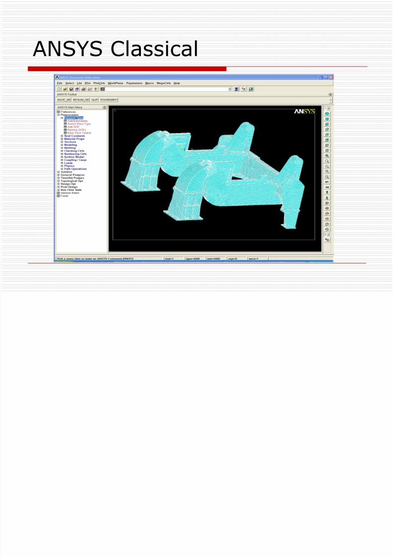
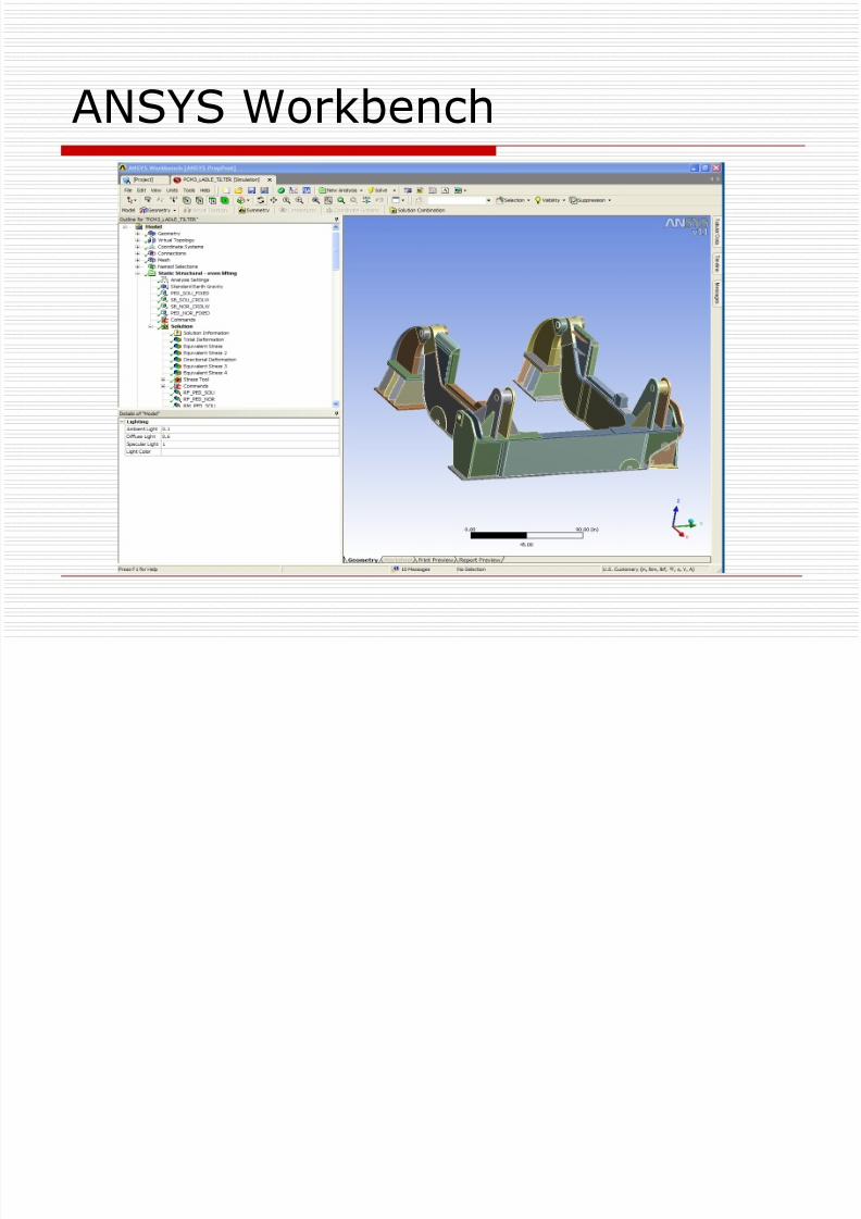
Two interfaces: classical and Workbench share thecore solvers
Workbench is easy to use, best suited for 3Dmodeling
Classical is more powerful, gives the user moreflexibilities
8/11/2019 pipe-fea 2
http://slidepdf.com/reader/full/pipe-fea-2 3/14
ANSYS Classical
8/11/2019 pipe-fea 2
http://slidepdf.com/reader/full/pipe-fea-2 4/14
ANSYS Workbench

8/11/2019 pipe-fea 2
http://slidepdf.com/reader/full/pipe-fea-2 5/14
FEA procedures

8/11/2019 pipe-fea 2
http://slidepdf.com/reader/full/pipe-fea-2 6/14
Pipe System To Be Analyzed
Long, large diameter, thin walled steelpipes
Lined with refractory and insulations
There is no other external loads exceptfor self weight
The pipes will see thermal growth atstart up
The roof of the bins may also move dueto thermal expansion at start up

8/11/2019 pipe-fea 2
http://slidepdf.com/reader/full/pipe-fea-2 7/14
FEA decisions
3D SOLID elements? – the model is too big!
2D SHELL elements? – possible, but still fairlyexpensive (in term of computing time and model
set up time) 1D BEAM elements – quick and easy, accurate
results for reaction forces and moments, whichmay be used in hand calculations for welds andguidance for support selections.
Detailed 3D / 2D sub models for Y-pipesection and diverters may be analyzed using the1D BEAM model results.

8/11/2019 pipe-fea 2
http://slidepdf.com/reader/full/pipe-fea-2 8/14
FEA load cases
The load steps the feed pipes may see: Erect Connect pipes to the bins
Start up, temperature going up (max. 200 C) Production cycles
A good understanding of eachload step is essential for the
success of the analysis!

8/11/2019 pipe-fea 2
http://slidepdf.com/reader/full/pipe-fea-2 9/14
FEA load cases
Load cases for the FEA model:0 Run one load case to determine the preload
required from the Spring support and size thespring
1. Room temperature; all support connectedexcept for the expansion joint; gravity loadapplied
2. Room temperature; all support connectedincluding the expansion joint; gravity loadapplied
3. Uniform max. temperature applied on pipes; allsupport connected including the expansion joint;gravity load applied; bin roof thermalmovements applied

8/11/2019 pipe-fea 2
http://slidepdf.com/reader/full/pipe-fea-2 10/14
FEA for pipes
“Skeleton” Line Model
Visual representation
of the beam modelBeam Model
Mesh

8/11/2019 pipe-fea 2
http://slidepdf.com/reader/full/pipe-fea-2 11/14
FEA for pipes
Element type PIPE16 (pipes and flanges): specialized BEAM element COMBIN14 (expansion joints & spring supports): Spring
elements
LINK 10 (cable support, if applicable): tension only linkelements
Real constants Each element is defined by Element Type and a set of
real constant values For example, “PIPE16 and Real constant set 2” tell
ANSYS these elements behave like a circular hollow
beam, OD=0.4064m, Wall thickness=0.0095m,… Material properties
Mild steel Increase the density for the pipes to match the density
of pipe+refractory+insulation

8/11/2019 pipe-fea 2
http://slidepdf.com/reader/full/pipe-fea-2 12/14
FEA Results for Pipes

8/11/2019 pipe-fea 2
http://slidepdf.com/reader/full/pipe-fea-2 13/14
FEA Results for Pipes
Displacement in all six degree of freedomsat any node
Reaction forces and moments at any node
Various stress results (bending stress, axialstress, shear stress, von-mises stress,principle stress…) for all elements
Physical properties of the model (volume,mass, moment of inertia…) based on themodel geometry

8/11/2019 pipe-fea 2
http://slidepdf.com/reader/full/pipe-fea-2 14/14