BAJA Presentation MIT Bellatores
15
2007 2009 2010 2011 2012 MIT FACULTY ADVISOR - Mr. AMIT KUMAR MARWAH TEAM CAPTIAN - RAHUL A WA TE BELLATORES 3D VIEWS
-
Upload
ashray-pawar -
Category
Documents
-
view
218 -
download
0
Transcript of BAJA Presentation MIT Bellatores
7/27/2019 BAJA Presentation MIT Bellatores
http://slidepdf.com/reader/full/baja-presentation-mit-bellatores 1/16
7/27/2019 BAJA Presentation MIT Bellatores
http://slidepdf.com/reader/full/baja-presentation-mit-bellatores 2/16
3D VIEWS
7/27/2019 BAJA Presentation MIT Bellatores
http://slidepdf.com/reader/full/baja-presentation-mit-bellatores 3/16
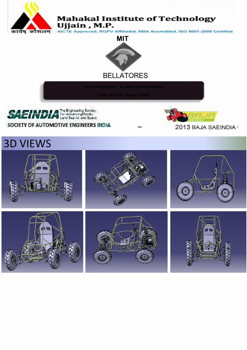
TECHNICAL SPECIFICATIONSENGINE
Type
Displacement c
Max. Torque N
Max Power , hp
TRANSMISS
Mahindra Alfa G
4 Forward- 1 re
STEERING
Rack And Pinio
SUSPENSIO
Front
Rear
BRAKES
Hydraulic Disc B
DIMENSION
Length (inches)
Width (inches)
Height (inches)
Weight Distribution (Total = 250kg)
51.2 KG
LEFT
76.5KG
48.8KG
RIGHT
73.5 KG
FRONT
REAR
WEIGHT
CENTER OF
WHEEL
Kerb Weight
Gross Weight
Front (OD x Wi
Rear (OD x Wid
CG wrt centreof firewall (mm
Y
Z
X
54”
Wheel Track
61” Wheel Base
7/27/2019 BAJA Presentation MIT Bellatores
http://slidepdf.com/reader/full/baja-presentation-mit-bellatores 4/16
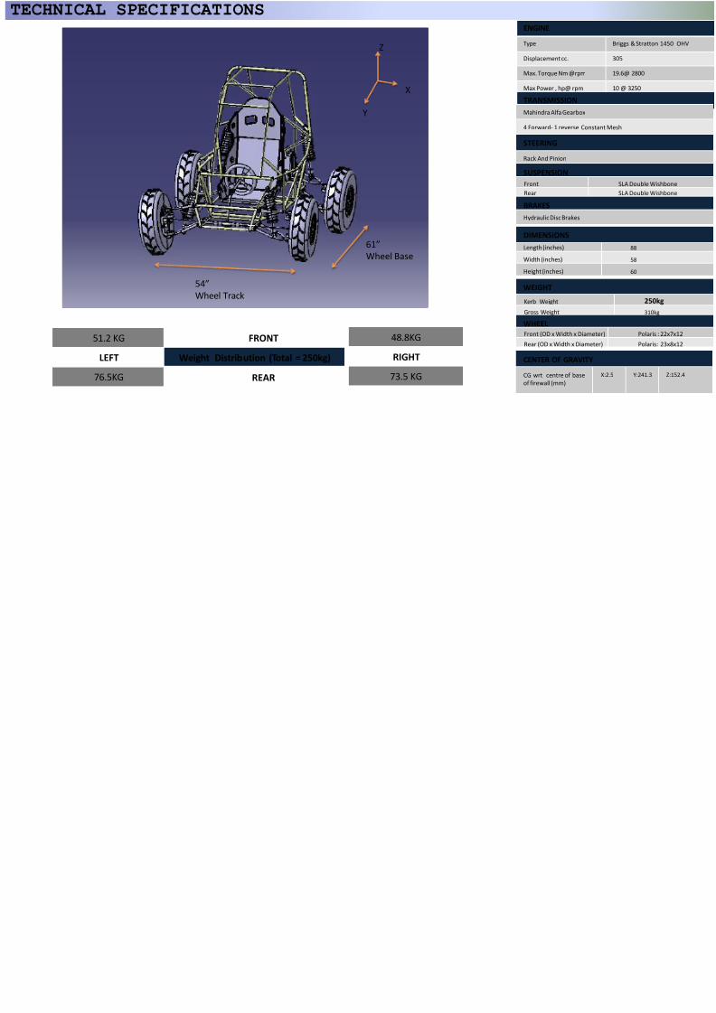
ROLL CAGE AND ERGONOMICSErgonomic Conditions
Parameter Std. Value Our Values Parameter
Angle at elbows 125⁰-140⁰ 132˚ Steering Wheel Dia.( mm)
Angle at Knees 120-⁰150⁰ 130˚ Angle of Steering Wheel
Angle at Back 8⁰-15⁰ 10 ̊
Salient Features
Adjustable Seat
Rulebook Conformance
Roll Cage Features
Parameter Value Parameter
Total Number of welds 81 Tube Outer Diameter mm
Weld Length 7 m Thickness of tube (mm)
Tubing Length 30.25 m Weight of tubing (Kg)
Parameter Allowable Value
Maximum vehicle width (inches) 64
Maximum vehicle length (inches) 108
Minimum firewall width at 27 inches above seat 29
Material used Steel alloys
Vertical distance of S.I.M. from seat (inches) 8 -14
Firewall angle in degrees Maximum 20
Firewall triangulation members -Upper
LowerLess than 5 inches
Angle- Greater than 20 deg
F.B.M. angle Less than 45 deg
Reach Bubble
Binocular Vision
7/27/2019 BAJA Presentation MIT Bellatores
http://slidepdf.com/reader/full/baja-presentation-mit-bellatores 5/16
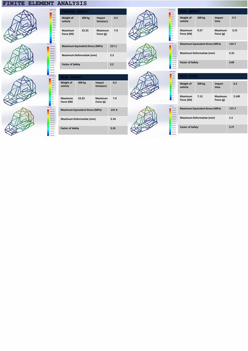
FINITE ELEMENT ANALYSIS
FRONTAL IMPACT SIDE IMPA
Weight of
vehicle
300 kg Impact
time(sec)
0.2
Maximum
Force (kN)
23.25 Maximum
Force (g)
7.9
Weight of
vehicle
Maximum
Force (kN)
Weight of
vehicle
300 kg Impact
time(sec)
0.2
Maximum
Force (kN)
23.25 Maximum
Force (g)
7.9
Weight of
vehicle
Maximum
Force (kN)
Maximum Equivalent Stress (MPa) 217.1
Maximum Deformation (mm) 2.3
Factor of Safety 2.2
Maximum Eq
Maximum De
Factor of Safe
Maximum Equivalent Stress (MPa) 137.4
Maximum Deformation (mm) 5.34
Factor of Safety 3.35
Maximum Eq
Maximum De
Factor of Safe
ROLL OVEREAR IMPACT
7/27/2019 BAJA Presentation MIT Bellatores
http://slidepdf.com/reader/full/baja-presentation-mit-bellatores 6/16
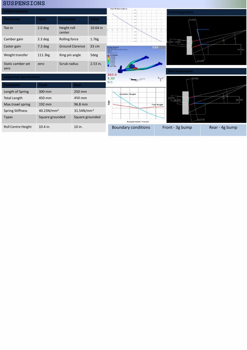
Front Suspensions
Rear Suspensions
Vehicle Dynamics
Parameter Value Parameter Value
Toe in 2.0 deg Height roll
center
10.64 in
Camber gain 2.3 deg Rolling force 1.76g
Caster gain 7.3 deg Ground Clarence 33 cm
Weight transfer 111.3kg King pin angle 5deg
Static camber set
zero
zero Scrub radius 2.53 in.
Suspension Specifications
Parameter Front RearLength of Spring 300 mm 250 mm
Total Length 450 mm 450 mm
Max.travel spring 192 mm 96.8 mm
Spring Stiffness 40.23N/mm2 31.54N/mm2
Types Square grounded Square grounded
Roll Centre Height 10.4 in. 10 in.
SUSPENSIONS
Boundary conditions Front - 3g bump
7/27/2019 BAJA Presentation MIT Bellatores
http://slidepdf.com/reader/full/baja-presentation-mit-bellatores 7/16
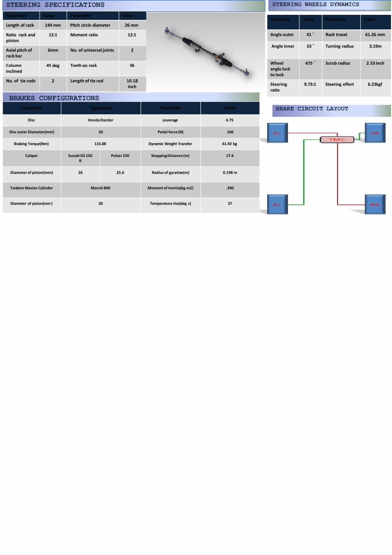
STEERING SPECIFICATIONS
Parameter Value Parameter Value
Length of rack 144 mm Pitch circle diameter 26 mm
Ratio rack and
pinion
12:1 Moment ratio 12:1
Axial pitch of
rack bar
6mm No. of universal joints 2
Column
inclined
45 deg Teeth on rack 36
No. of tie rods 2 Length of tie rod 10.18
inch
STEERING W
Parameter Va
Angle outer 4
Angle inner 3
Wheel
angle lockto lock
47
Steering
ratio
9.7
BRAKES CONFIGURATIONS
Parameter Type/value Parameter Value
Disc Honda Dazzler Leverage 4.75
Disc outer Diameter(mm) 20 Pedal force (N) 160
Braking Torque(Nm) 115.08 Dynamic Weight Transfer 61.92 kg
Caliper Suzuki GS 150
R
Pulsar 220 Stopping Distance (m) 17.6
Diameter of piston(mm) 26 25.6 Radius of gyration(m) 0.198 m
Tandem Master Cylinder Maruti 800 Moment of inertia(kg.m2) .390
Diameter of piston(mm) 20 Temperature rise(deg c) 37
BRAKE CIR
7/27/2019 BAJA Presentation MIT Bellatores
http://slidepdf.com/reader/full/baja-presentation-mit-bellatores 8/16
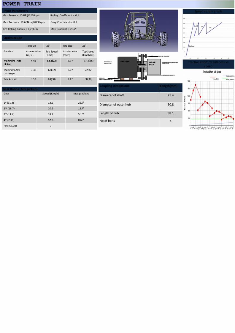
Input Parameters
POWER TRAIN
Optimization
Gear Speed (Kmph) Max gradient
1st (31.45) 12.2 26.7⁰
2nd (18.7) 20.5 12.7⁰
3rd (11.4) 33.7 5.16⁰
4th (7.35) 52.3 0.60⁰
Rev (55.08) 7
Tire Size 23” Tire Size 25”
Gearbox Acceleration
(m/s²)
Top Speed
(Time)
Acceleration
(m/s²)
Top Speed
(kmph) (s)
Mahindra Alfa
pickup
4.46 52.3(22) 3.97 57.3(36)
Mahindra Alfa
passenger
3.36 67(32) 3.07 72(42)
Tata Ace zip 3.52 63(30) 3.17 68(38)
Max Power = 10 HP@3250 rpm Rolling Coefficient = 0.1
Max Torque = 19.66Nm@2800 rpm Drag Coefficient = 0.9
Tire Rolling Radius = 0.286 m Max Gradient = 26.7⁰
Gear Ratios (Alfa pickup)Coupling Dimensions Length(mm)
Diameter of shaft 25.4
Diameter of outer hub 50.8
Length of hub 38.1
No of bolts 4
7/27/2019 BAJA Presentation MIT Bellatores
http://slidepdf.com/reader/full/baja-presentation-mit-bellatores 9/16
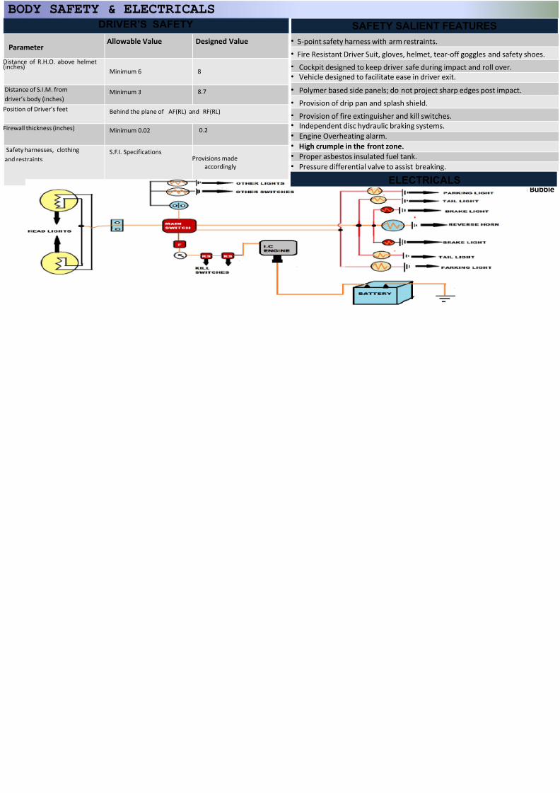
BODY SAFETY & ELECTRICALS
• 5-point safety harness with arm restraints.
• Fire Resistant Driver Suit, gloves, helmet, te
• Cockpit designed to keep driver safe during
• Vehicle designed to facilitate ease in driver
• Polymer based side panels; do not project s
• Provision of drip pan and splash shield.
• Provision of fire extinguisher and kill switch
• Independent disc hydraulic braking systems
• Engine Overheating alarm.
• High crumple in the front zone.
• Proper asbestos insulated fuel tank.
• Pressure differential valve to assist breaking
SAFETY SALIENT DRIVER’S SAFETY
Parameter Allowable Value Designed Value
Distance of R.H.O. above helmet(inches)
Minimum 6 8
Distance of S.I.M. from
driver’s body (inches)
Minimum 3 8.7
Position of Driver’s feet Behind the plane of AF(RL) and RF(RL)
Firewall thickness (inches) Minimum 0.02 0.2
Safety harnesses, clothing
and restraintsS.F.I. Specifications
Provisions made
accordingly
Binocular VisionELECTRICA
7/27/2019 BAJA Presentation MIT Bellatores
http://slidepdf.com/reader/full/baja-presentation-mit-bellatores 10/16
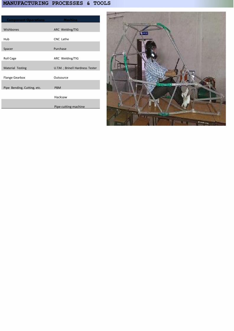
MANUFACTURING PROCESSES & TOOLS
Component/Operations Machine
Wishbones ARC Welding/TIG
Hub CNC Lathe
Spacer Purchase
Roll Cage ARC Welding/TIG
Material Testing U.T.M. ; Brinell Hardness Tester
Flange Gearbox Outsource
Pipe Bending, Cutting, etc. PBM
Hacksaw
Pipe cutting machine
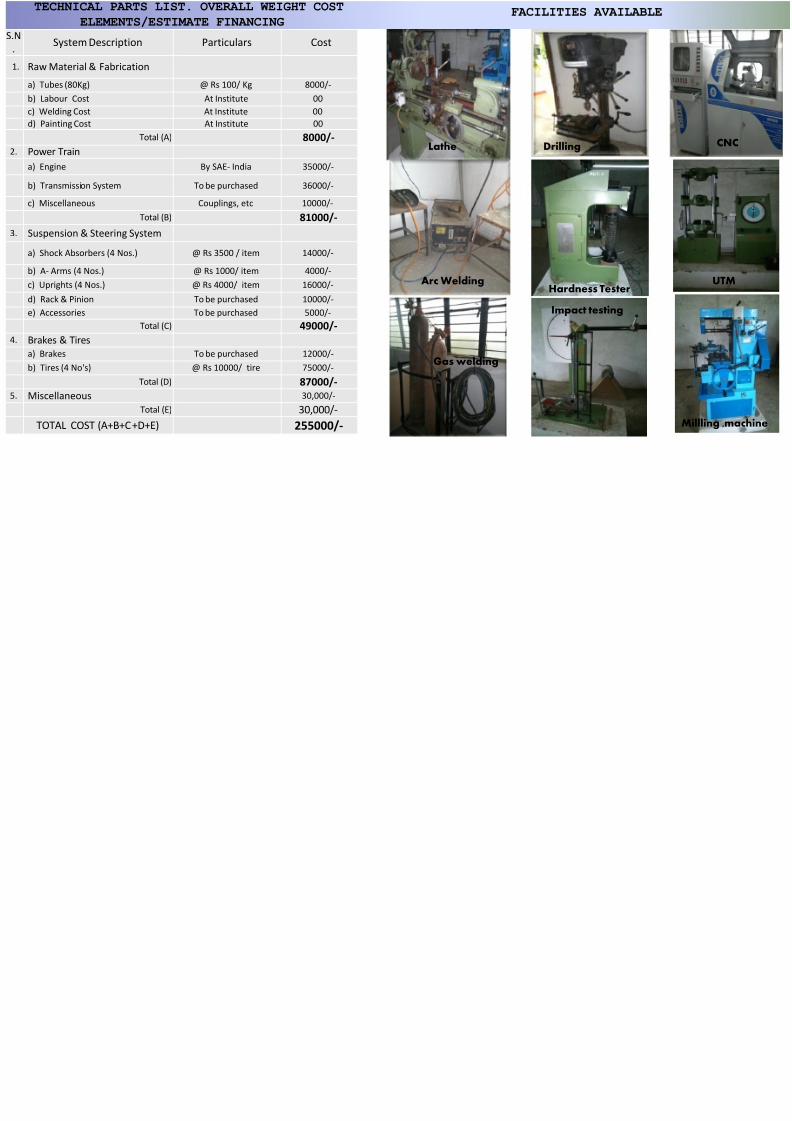
TECHNICAL PARTS LIST OVERALL WEIGHT COST
7/27/2019 BAJA Presentation MIT Bellatores
http://slidepdf.com/reader/full/baja-presentation-mit-bellatores 11/16
TECHNICAL PARTS LIST. OVERALL WEIGHT COST
ELEMENTS/ESTIMATE FINANCINGS.N
. System Description Particulars Cost
1. Raw Material & Fabrication
a) Tubes (80Kg) @ Rs 100/ Kg 8000/-
b) Labour Cost At Institute 00
c) Welding Cost At Institute 00
d) Painting Cost At Institute 00
Total (A) 8000/-2. Power Train
a) Engine By SAE- India 35000/-
b) Transmission System To be purchased 36000/-
c) Miscellaneous Couplings, etc 10000/-
Total (B) 81000/-
3. Suspension & Steering System
a) Shock Absorbers (4 Nos.) @ Rs 3500 / item 14000/-
b) A- Arms (4 Nos.) @ Rs 1000/ item 4000/-
c) Uprights (4 Nos.) @ Rs 4000/ item 16000/-
d) Rack & Pinion To be purchased 10000/-
e) Accessories To be purchased 5000/-
Total (C) 49000/-
4. Brakes & Tires
a) Brakes To be purchased 12000/-
b) Tires (4 No's) @ Rs 10000/ tire 75000/-
Total (D) 87000/-
5. Miscellaneous 30,000/-
Total (E) 30,000/-
TOTAL COST (A+B+C+D+E) 255000/-
Lathe Drilling
Arc WeldingHardness Teste
Gas welding
Impact testing
FACILITIES AVAI
7/27/2019 BAJA Presentation MIT Bellatores
http://slidepdf.com/reader/full/baja-presentation-mit-bellatores 12/16
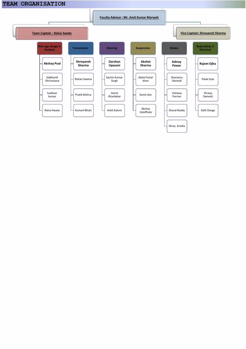
Roll cage design &Analysis
Akshay Poal
SiddharthShrivastava
Sudheerkumar
Rahul Awate
Transmission
ShreyanshSharma
Rohan Saxena
Pratik Mishra
Kumaril Bhatt
Steering
DarshanUpasani
Sachin KumarSingh
HarshKhardekar
Ankit Kalore
Suspension
AkshatSharma
Abdul Faizalkhan
Asmit Jain
AkshayUpadhyay
Brakes
AshrayPawar
ShantanuDwivedi
VishwasParmar
Sharat Reddy
Shrey Arodia
Faculty Advisor : Mr. Amit Kumar Marwah
Team Captain : Rahul Awate Vice Capt
TEAM ORGANISATION
7/27/2019 BAJA Presentation MIT Bellatores
http://slidepdf.com/reader/full/baja-presentation-mit-bellatores 13/16
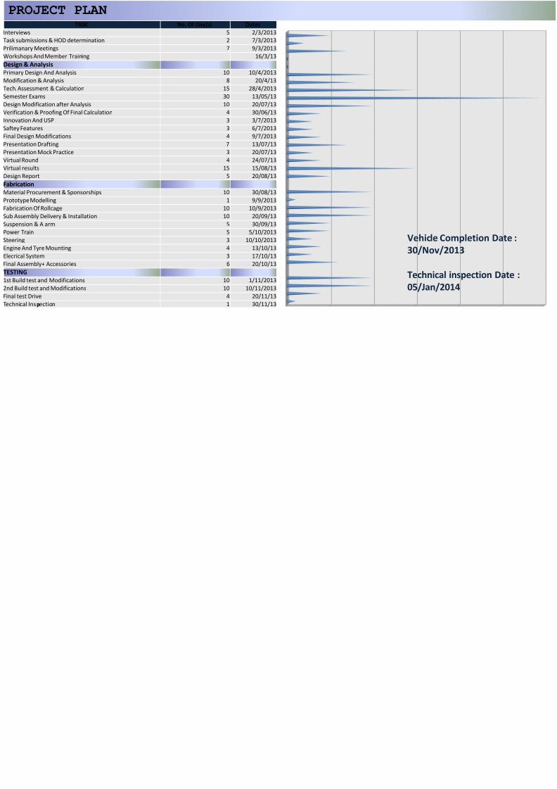
PROJECT PLAN
Vehicle
30/Nov
Technic
05/Jan/
TASK No. Of Day(s) Dates
Interviews 5 2/3/2013
Task submissions & HOD determination 2 7/3/2013
Prilimanary Meetings 7 9/3/2013
Workshops And Member Training 16/3/13
Design & Analysis
Primary Design And Analysis 10 10/4/2013
Modification & Analysis 8 20/4/13
Tech. Assessment & Calculation 15 28/4/2013
Semester Exams 30 13/05/13 Design Modification after Analysis 10 20/07/13
Verification & Proofing Of Final Calculation 4 30/06/13
Innovation And USP 3 3/7/2013
Saftey Features 3 6/7/2013
Final Design Modifications 4 9/7/2013
Presentation Drafting 7 13/07/13
Presentation Mock Practice 3 20/07/13
Virtual Round 4 24/07/13
Virtual results 15 15/08/13
Design Report 5 20/08/13
Fabrication
Material Procurement & Sponsorships 10 30/08/13 Prototype Modelling 1 9/9/2013
Fabrication Of Rollcage 10 10/9/2013
Sub Assembly Delivery & Installation 10 20/09/13
Suspension & A arm 5 30/09/13
Power Train 5 5/10/2013
Steering 3 10/10/2013
Engine And Tyre Mounting 4 13/10/13
Elecrical System 3 17/10/13
Final Assembly+ Accessories 6 20/10/13
TESTING
1st Build test and Modifications 10 1/11/2013
2nd Build test and Modifications 10 10/11/2013
Final test Drive 4 20/11/13
Technical Ins ection 1 30/11/13
7/27/2019 BAJA Presentation MIT Bellatores
http://slidepdf.com/reader/full/baja-presentation-mit-bellatores 14/16
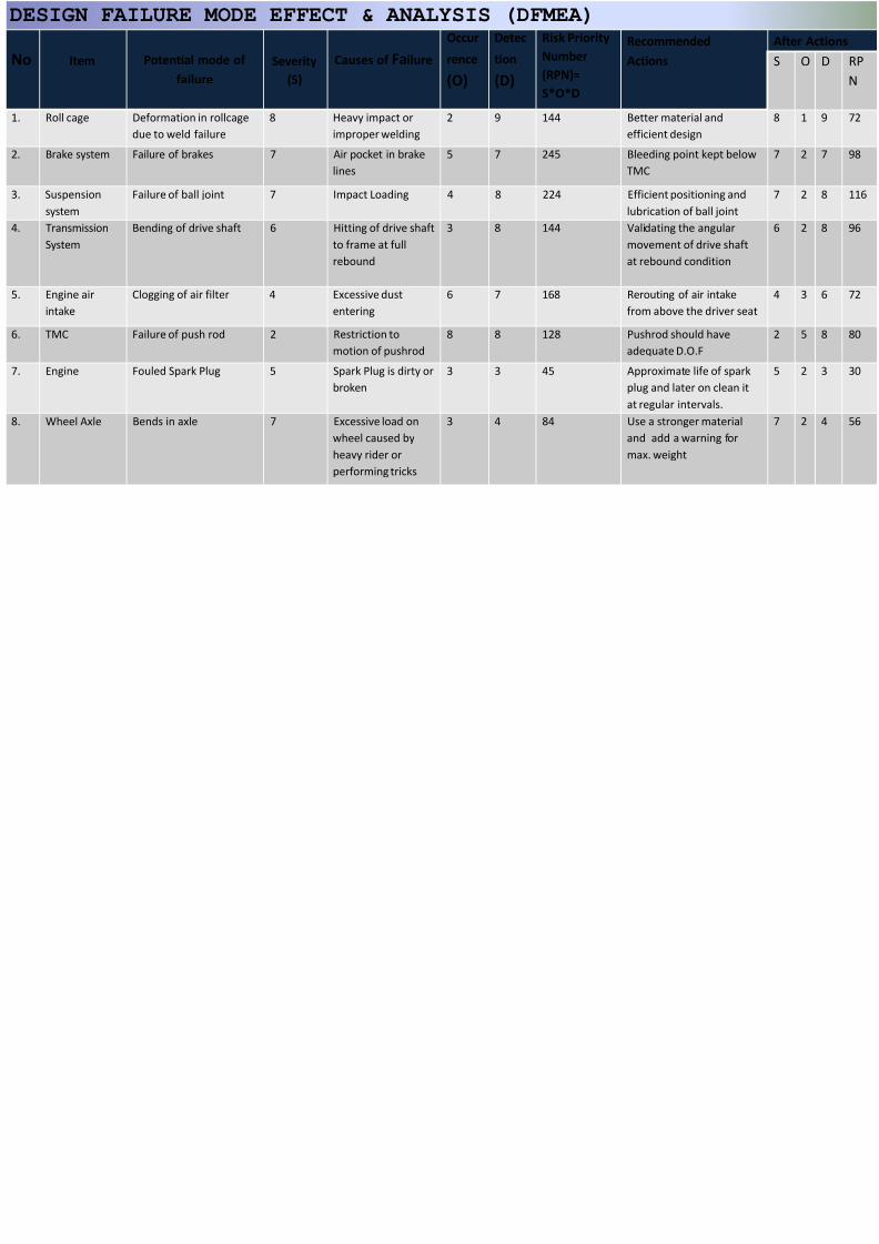
No Item Potential mode of
failure
Severity
(S)
Causes of Failure
Occur
rence
(O)
Detec
tion
(D)
Risk Priority
Number
(RPN)=
S*O*D
Recommend
Actions
1. Roll cage Deformation in rollcage
due to weld failure
8 Heavy impact or
improper welding
2 9 144 Better mater
efficient desig
2. Brake system Failure of brakes 7 Air pocket in brakelines
5 7 245 Bleeding poinTMC
3. Suspension
system
Failure of ball joint 7 Impact Loading 4 8 224 Efficient posit
lubrication of
4. Transmission
System
Bending of drive shaft 6 Hitting of drive shaft
to frame at full
rebound
3 8 144 Validating the
movement of
at rebound co
5. Engine air
intake
Clogging of air filter 4 Excessive dust
entering
6 7 168 Rerouting of
from above t
6. TMC Failure of push rod 2 Restriction to
motion of pushrod
8 8 128 Pushrod shou
adequate D.O
7. Engine Fouled Spark Plug 5 Spark Plug is dirty or
broken
3 3 45 Approximate
plug and late
at regular int
8. Wheel Axle Bends in axle 7 Excessive load on
wheel caused by
heavy rider or
performing tricks
3 4 84 Use a stronge
and add a wa
max. weight
DESIGN FAILURE MODE EFFECT & ANALYSIS (DFMEA)
7/27/2019 BAJA Presentation MIT Bellatores
http://slidepdf.com/reader/full/baja-presentation-mit-bellatores 15/16
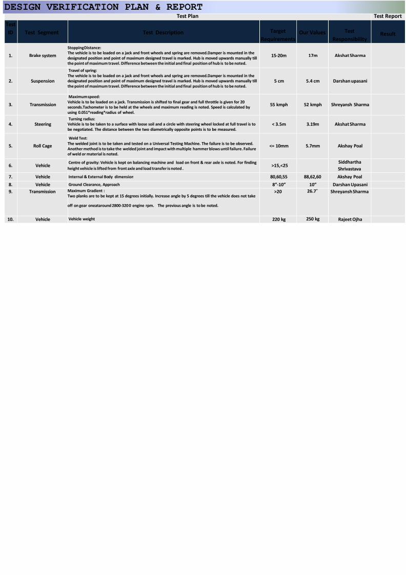
Test Plan
Test
ID Test Segment Test Description Target
Requirements
Our Valu
1. Brake system
Stopping Distance:
The vehicle is to be loaded on a jack and front wheels and spring are removed.Damper is mounted in the
designated position and point of maximum designed travel is marked. Hub is moved upwards manually till
the point of maximum travel. Difference between the initial and final position of hub is to be noted.
15-20m 17m
2. Suspension
Travel of spring:The vehicle is to be loaded on a jack and front wheels and spring are removed.Damper is mounted in the
designated position and point of maximum designed travel is marked. Hub is moved upwards manually till
the point of maximum travel. Difference between the initial and final position of hub is to be noted.
5 cm 5.4 cm
3. Transmission
Maximum speed:
Vehicle is to be loaded on a jack. Transmission is shifted to final gear and full throttle is given for 20
seconds.Tachometer is to be held at the wheels and maximum reading is noted. Speed is calculated by
using 0.051*reading*radius of wheel.
55 kmph 52 kmp
4. SteeringTurning radius:
Vehicle is to be taken to a surface with loose soil and a circle with steering wheel locked at full travel is to
be negotiated. The distance between the two diametrically opposite points is to be measured.< 3.5m 3.19m
5. Roll Cage
Weld Test:
The welded joint is to be taken and tested on a Universal Testing Machine. The failure is to be observed.Another method is to take the welded joint and impact with multiple hammer blows until failure. Failure
of weld or material is noted.
<= 10mm 5.7mm
6. VehicleCentre of gravity: Vehicle is kept on balancing machine and load on front & rear axle is noted. For finding
height vehicle is lifted from front axle and load transfer is noted .>15,<25
7. Vehicle Internal & External Body dimension 80,60,55 88,62,6
8. Vehicle Ground Clearance, Approach 8”-10” 10”
9. Transmission Maximum Gradient :
Two planks are to be kept at 15 degrees initially. Increase angle by 5 degrees till the vehicle does not take
off on gear oneataround 2800-3200 engine rpm. The previous angle is to be noted.
>20 26.7˚
10. Vehicle Vehicle weight 220 kg 250 kg
DESIGN VERIFICATION PLAN & REPORT

7/27/2019 BAJA Presentation MIT Bellatores
http://slidepdf.com/reader/full/baja-presentation-mit-bellatores 16/16


![Seres Mit[1]..](https://static.fdocuments.ec/doc/165x107/559f18a11a28abc5348b4877/seres-mit1.jpg)