UPV QuickStartGuide en 07
227
R&S ® UPV Audio Analyzer Quick Start Guide Quick Start Guide (;^DÜÌ) 1146.2078.62 ─ 07 Test & Measurement
-
Upload
melanie-hood -
Category
Documents
-
view
239 -
download
2
Transcript of UPV QuickStartGuide en 07
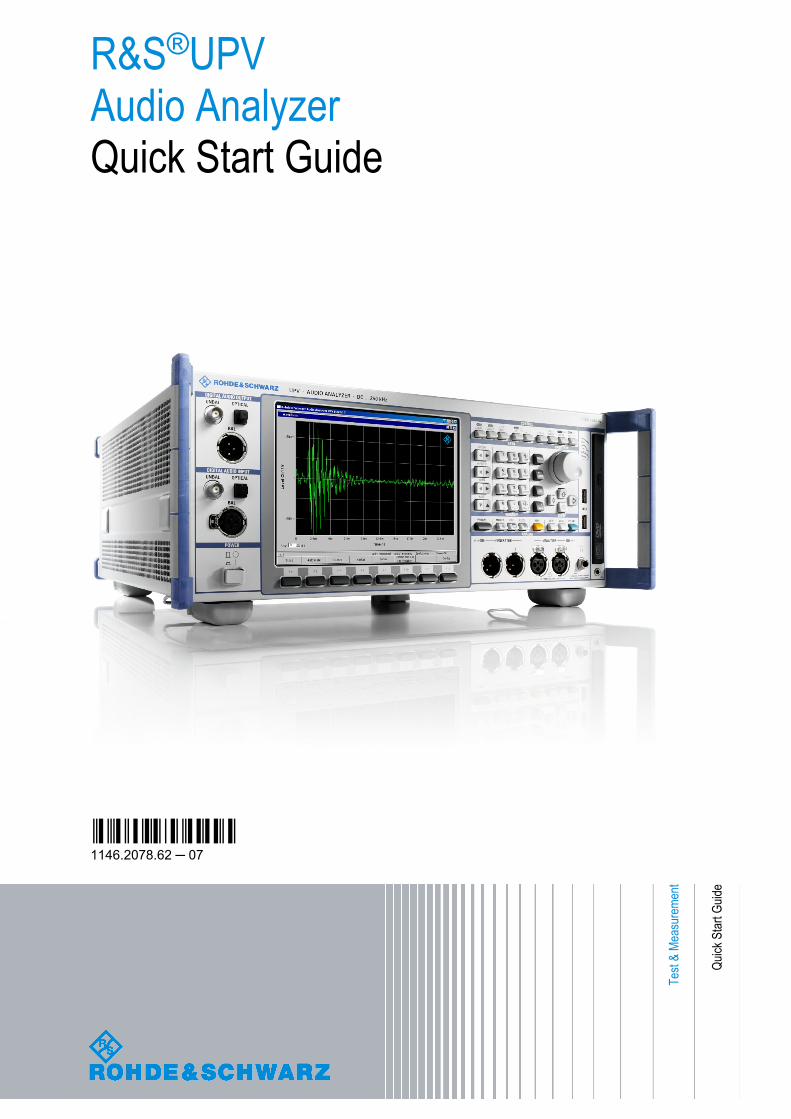
R&S®UPVAudio AnalyzerQuick Start Guide
Quick
Star
t Guid
e
(;^DÜÌ)1146.2078.62 ─ 07
Test
& Me
asur
emen
t
This manual applies to the following audio analyzers with their options:R&S®UPVR&S®UPV66
The firmware of the instrument makes use of several valuable open source software packages. For information, see the "Open SourceAcknowledgement" on the user documentation CD-ROM (included in delivery).Rohde & Schwarz would like to thank the open source community for their valuable contribution to embedded computing.
© 2012 Rohde & Schwarz GmbH & Co. KGMuehldorfstr. 15, 81671 Munich, GermanyPhone: +49 89 41 29 - 0Fax: +49 89 41 29 12 164E-mail: [email protected]: http://www.rohde-schwarz.comPrinted in Germany – Subject to change – Data without tolerance limits is not binding.R&S® is a registered trademark of Rohde & Schwarz GmbH & Co. KG.Trade names are trademarks of the owners.
The following abbreviation is used throughout the manual: R&S®UPV is abbreviated as R&S UPV.
1171.0000.42 - 07 Page 1
Basic Safety Instructions Always read through and comply with the following safety instructions!
All plants and locations of the Rohde & Schwarz group of companies make every effort to keep the safety standards of our products up to date and to offer our customers the highest possible degree of safety. Our products and the auxiliary equipment they require are designed, built and tested in accordance with the safety standards that apply in each case. Compliance with these standards is continuously monitored by our quality assurance system. The product described here has been designed, built and tested in accordance with the EC Certificate of Conformity and has left the manufacturer’s plant in a condition fully complying with safety standards. To maintain this condition and to ensure safe operation, you must observe all instructions and warnings provided in this manual. If you have any questions regarding these safety instructions, the Rohde & Schwarz group of companies will be happy to answer them.
Furthermore, it is your responsibility to use the product in an appropriate manner. This product is designed for use solely in industrial and laboratory environments or, if expressly permitted, also in the field and must not be used in any way that may cause personal injury or property damage. You are responsible if the product is used for any purpose other than its designated purpose or in disregard of the manufacturer's instructions. The manufacturer shall assume no responsibility for such use of the product.
The product is used for its designated purpose if it is used in accordance with its product documentation and within its performance limits (see data sheet, documentation, the following safety instructions). Using the product requires technical skills and, in some cases, a basic knowledge of English. It is therefore essential that only skilled and specialized staff or thoroughly trained personnel with the required skills be allowed to use the product. If personal safety gear is required for using Rohde & Schwarz products, this will be indicated at the appropriate place in the product documentation. Keep the basic safety instructions and the product documentation in a safe place and pass them on to the subsequent users.
Observing the safety instructions will help prevent personal injury or damage of any kind caused by dangerous situations. Therefore, carefully read through and adhere to the following safety instructions before and when using the product. It is also absolutely essential to observe the additional safety instructions on personal safety, for example, that appear in relevant parts of the product documentation. In these safety instructions, the word "product" refers to all merchandise sold and distributed by the Rohde & Schwarz group of companies, including instruments, systems and all accessories. For product-specific information, see the data sheet and the product documentation.
Safety labels on products
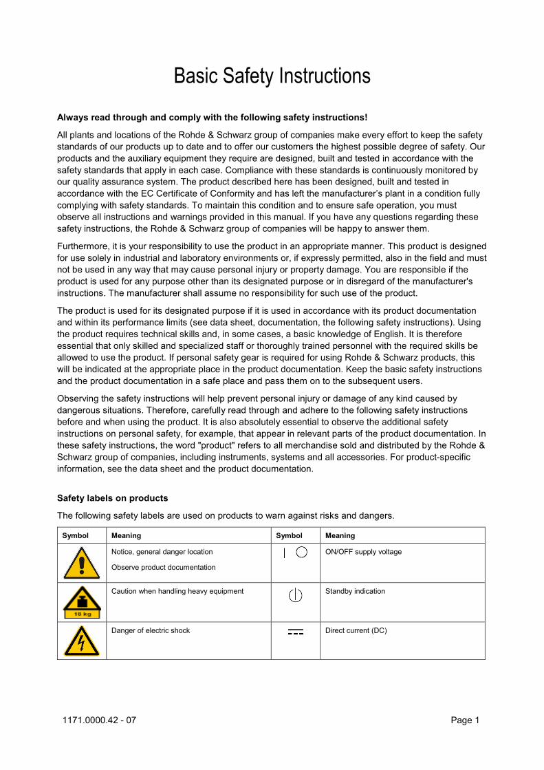
The following safety labels are used on products to warn against risks and dangers.
Symbol Meaning Symbol Meaning
Notice, general danger location
Observe product documentation
ON/OFF supply voltage
Caution when handling heavy equipment Standby indication
Danger of electric shock Direct current (DC)
Basic Safety Instructions
1171.0000.42 - 07 Page 2
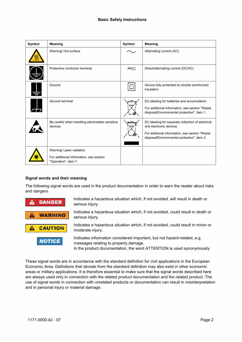
Symbol Meaning Symbol Meaning
Warning! Hot surface Alternating current (AC)
Protective conductor terminal Direct/alternating current (DC/AC)
Ground Device fully protected by double (reinforced) insulation
Ground terminal EU labeling for batteries and accumulators
For additional information, see section "Waste disposal/Environmental protection", item 1.
Be careful when handling electrostatic sensitive devices
EU labeling for separate collection of electrical and electronic devices
For additonal information, see section "Waste disposal/Environmental protection", item 2.
Warning! Laser radiation
For additional information, see section "Operation", item 7.
Signal words and their meaning
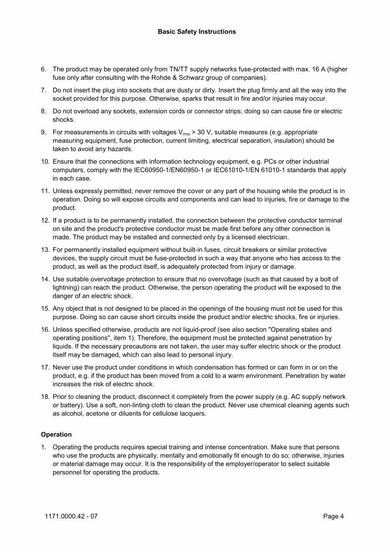
The following signal words are used in the product documentation in order to warn the reader about risks and dangers.
Indicates a hazardous situation which, if not avoided, will result in death or serious injury.
Indicates a hazardous situation which, if not avoided, could result in death or serious injury.
Indicates a hazardous situation which, if not avoided, could result in minor or moderate injury.
Indicates information considered important, but not hazard-related, e.g. messages relating to property damage. In the product documentation, the word ATTENTION is used synonymously.
These signal words are in accordance with the standard definition for civil applications in the European Economic Area. Definitions that deviate from the standard definition may also exist in other economic areas or military applications. It is therefore essential to make sure that the signal words described here are always used only in connection with the related product documentation and the related product. The use of signal words in connection with unrelated products or documentation can result in misinterpretation and in personal injury or material damage.
Basic Safety Instructions
1171.0000.42 - 07 Page 3
Operating states and operating positions
The product may be operated only under the operating conditions and in the positions specified by the manufacturer, without the product's ventilation being obstructed. If the manufacturer's specifications are not observed, this can result in electric shock, fire and/or serious personal injury or death. Applicable local or national safety regulations and rules for the prevention of accidents must be observed in all work performed.
1. Unless otherwise specified, the following requirements apply to Rohde & Schwarz products: predefined operating position is always with the housing floor facing down, IP protection 2X, use only indoors, max. operating altitude 2000 m above sea level, max. transport altitude 4500 m above sea level. A tolerance of ±10 % shall apply to the nominal voltage and ±5 % to the nominal frequency, overvoltage category 2, pollution severity 2.
2. Do not place the product on surfaces, vehicles, cabinets or tables that for reasons of weight or stability are unsuitable for this purpose. Always follow the manufacturer's installation instructions when installing the product and fastening it to objects or structures (e.g. walls and shelves). An installation that is not carried out as described in the product documentation could result in personal injury or even death.
3. Do not place the product on heat-generating devices such as radiators or fan heaters. The ambient temperature must not exceed the maximum temperature specified in the product documentation or in the data sheet. Product overheating can cause electric shock, fire and/or serious personal injury or even death.
Electrical safety
If the information on electrical safety is not observed either at all or to the extent necessary, electric shock, fire and/or serious personal injury or death may occur.
1. Prior to switching on the product, always ensure that the nominal voltage setting on the product matches the nominal voltage of the AC supply network. If a different voltage is to be set, the power fuse of the product may have to be changed accordingly.
2. In the case of products of safety class I with movable power cord and connector, operation is permitted only on sockets with a protective conductor contact and protective conductor.
3. Intentionally breaking the protective conductor either in the feed line or in the product itself is not permitted. Doing so can result in the danger of an electric shock from the product. If extension cords or connector strips are implemented, they must be checked on a regular basis to ensure that they are safe to use.
4. If there is no power switch for disconnecting the product from the AC supply network, or if the power switch is not suitable for this purpose, use the plug of the connecting cable to disconnect the product from the AC supply network. In such cases, always ensure that the power plug is easily reachable and accessible at all times. For example, if the power plug is the disconnecting device, the length of the connecting cable must not exceed 3 m. Functional or electronic switches are not suitable for providing disconnection from the AC supply network. If products without power switches are integrated into racks or systems, the disconnecting device must be provided at the system level.
5. Never use the product if the power cable is damaged. Check the power cables on a regular basis to ensure that they are in proper operating condition. By taking appropriate safety measures and carefully laying the power cable, ensure that the cable cannot be damaged and that no one can be hurt by, for example, tripping over the cable or suffering an electric shock.
Basic Safety Instructions
1171.0000.42 - 07 Page 4
6. The product may be operated only from TN/TT supply networks fuse-protected with max. 16 A (higher fuse only after consulting with the Rohde & Schwarz group of companies).
7. Do not insert the plug into sockets that are dusty or dirty. Insert the plug firmly and all the way into the socket provided for this purpose. Otherwise, sparks that result in fire and/or injuries may occur.
8. Do not overload any sockets, extension cords or connector strips; doing so can cause fire or electric shocks.
9. For measurements in circuits with voltages Vrms > 30 V, suitable measures (e.g. appropriate measuring equipment, fuse protection, current limiting, electrical separation, insulation) should be taken to avoid any hazards.
10. Ensure that the connections with information technology equipment, e.g. PCs or other industrial computers, comply with the IEC60950-1/EN60950-1 or IEC61010-1/EN 61010-1 standards that apply in each case.
11. Unless expressly permitted, never remove the cover or any part of the housing while the product is in operation. Doing so will expose circuits and components and can lead to injuries, fire or damage to the product.
12. If a product is to be permanently installed, the connection between the protective conductor terminal on site and the product's protective conductor must be made first before any other connection is made. The product may be installed and connected only by a licensed electrician.
13. For permanently installed equipment without built-in fuses, circuit breakers or similar protective devices, the supply circuit must be fuse-protected in such a way that anyone who has access to the product, as well as the product itself, is adequately protected from injury or damage.
14. Use suitable overvoltage protection to ensure that no overvoltage (such as that caused by a bolt of lightning) can reach the product. Otherwise, the person operating the product will be exposed to the danger of an electric shock.
15. Any object that is not designed to be placed in the openings of the housing must not be used for this purpose. Doing so can cause short circuits inside the product and/or electric shocks, fire or injuries.
16. Unless specified otherwise, products are not liquid-proof (see also section "Operating states and operating positions", item 1). Therefore, the equipment must be protected against penetration by liquids. If the necessary precautions are not taken, the user may suffer electric shock or the product itself may be damaged, which can also lead to personal injury.
17. Never use the product under conditions in which condensation has formed or can form in or on the product, e.g. if the product has been moved from a cold to a warm environment. Penetration by water increases the risk of electric shock.
18. Prior to cleaning the product, disconnect it completely from the power supply (e.g. AC supply network or battery). Use a soft, non-linting cloth to clean the product. Never use chemical cleaning agents such as alcohol, acetone or diluents for cellulose lacquers.
Operation
1. Operating the products requires special training and intense concentration. Make sure that persons who use the products are physically, mentally and emotionally fit enough to do so; otherwise, injuries or material damage may occur. It is the responsibility of the employer/operator to select suitable personnel for operating the products.
Basic Safety Instructions
1171.0000.42 - 07 Page 5
2. Before you move or transport the product, read and observe the section titled "Transport".
3. As with all industrially manufactured goods, the use of substances that induce an allergic reaction (allergens) such as nickel cannot be generally excluded. If you develop an allergic reaction (such as a skin rash, frequent sneezing, red eyes or respiratory difficulties) when using a Rohde & Schwarz product, consult a physician immediately to determine the cause and to prevent health problems or stress.
4. Before you start processing the product mechanically and/or thermally, or before you take it apart, be sure to read and pay special attention to the section titled "Waste disposal/Environmental protection", item 1.
5. Depending on the function, certain products such as RF radio equipment can produce an elevated level of electromagnetic radiation. Considering that unborn babies require increased protection, pregnant women must be protected by appropriate measures. Persons with pacemakers may also be exposed to risks from electromagnetic radiation. The employer/operator must evaluate workplaces where there is a special risk of exposure to radiation and, if necessary, take measures to avert the potential danger.
6. Should a fire occur, the product may release hazardous substances (gases, fluids, etc.) that can cause health problems. Therefore, suitable measures must be taken, e.g. protective masks and protective clothing must be worn.
7. Laser products are given warning labels that are standardized according to their laser class. Lasers can cause biological harm due to the properties of their radiation and due to their extremely concentrated electromagnetic power. If a laser product (e.g. a CD/DVD drive) is integrated into a Rohde & Schwarz product, absolutely no other settings or functions may be used as described in the product documentation. The objective is to prevent personal injury (e.g. due to laser beams).
8. EMC classes (in line with EN 55011/CISPR 11, and analogously with EN 55022/CISPR 22, EN 55032/CISPR 32) − Class A equipment:
Equipment suitable for use in all environments except residential environments and environments that are directly connected to a low-voltage supply network that supplies residential buildings Note: Class A equipment is intended for use in an industrial environment. This equipment may cause radio disturbances in residential environments, due to possible conducted as well as radiated disturbances. In this case, the operator may be required to take appropriate measures to eliminate these disturbances.
− Class B equipment: Equipment suitable for use in residential environments and environments that are directly connected to a low-voltage supply network that supplies residential buildings
Repair and service
1. The product may be opened only by authorized, specially trained personnel. Before any work is performed on the product or before the product is opened, it must be disconnected from the AC supply network. Otherwise, personnel will be exposed to the risk of an electric shock.
Basic Safety Instructions
1171.0000.42 - 07 Page 6
2. Adjustments, replacement of parts, maintenance and repair may be performed only by electrical experts authorized by Rohde & Schwarz. Only original parts may be used for replacing parts relevant to safety (e.g. power switches, power transformers, fuses). A safety test must always be performed after parts relevant to safety have been replaced (visual inspection, protective conductor test, insulation resistance measurement, leakage current measurement, functional test). This helps ensure the continued safety of the product.
Batteries and rechargeable batteries/cells
If the information regarding batteries and rechargeable batteries/cells is not observed either at all or to the extent necessary, product users may be exposed to the risk of explosions, fire and/or serious personal injury, and, in some cases, death. Batteries and rechargeable batteries with alkaline electrolytes (e.g. lithium cells) must be handled in accordance with the EN 62133 standard.
1. Cells must not be taken apart or crushed.
2. Cells or batteries must not be exposed to heat or fire. Storage in direct sunlight must be avoided. Keep cells and batteries clean and dry. Clean soiled connectors using a dry, clean cloth.
3. Cells or batteries must not be short-circuited. Cells or batteries must not be stored in a box or in a drawer where they can short-circuit each other, or where they can be short-circuited by other conductive materials. Cells and batteries must not be removed from their original packaging until they are ready to be used.
4. Cells and batteries must not be exposed to any mechanical shocks that are stronger than permitted.
5. If a cell develops a leak, the fluid must not be allowed to come into contact with the skin or eyes. If contact occurs, wash the affected area with plenty of water and seek medical aid.
6. Improperly replacing or charging cells or batteries that contain alkaline electrolytes (e.g. lithium cells) can cause explosions. Replace cells or batteries only with the matching Rohde & Schwarz type (see parts list) in order to ensure the safety of the product.
7. Cells and batteries must be recycled and kept separate from residual waste. Rechargeable batteries and normal batteries that contain lead, mercury or cadmium are hazardous waste. Observe the national regulations regarding waste disposal and recycling.
Transport
1. The product may be very heavy. Therefore, the product must be handled with care. In some cases, the user may require a suitable means of lifting or moving the product (e.g. with a lift-truck) to avoid back or other physical injuries.
2. Handles on the products are designed exclusively to enable personnel to transport the product. It is therefore not permissible to use handles to fasten the product to or on transport equipment such as cranes, fork lifts, wagons, etc. The user is responsible for securely fastening the products to or on the means of transport or lifting. Observe the safety regulations of the manufacturer of the means of transport or lifting. Noncompliance can result in personal injury or material damage.
3. If you use the product in a vehicle, it is the sole responsibility of the driver to drive the vehicle safely and properly. The manufacturer assumes no responsibility for accidents or collisions. Never use the product in a moving vehicle if doing so could distract the driver of the vehicle. Adequately secure the product in the vehicle to prevent injuries or other damage in the event of an accident.
Instrucciones de seguridad elementales
1171.0000.42 - 07 Page 7
Waste disposal/Environmental protection
1. Specially marked equipment has a battery or accumulator that must not be disposed of with unsorted municipal waste, but must be collected separately. It may only be disposed of at a suitable collection point or via a Rohde & Schwarz customer service center.
2. Waste electrical and electronic equipment must not be disposed of with unsorted municipal waste, but must be collected separately. Rohde & Schwarz GmbH & Co. KG has developed a disposal concept and takes full responsibility for take-back obligations and disposal obligations for manufacturers within the EU. Contact your Rohde & Schwarz customer service center for environmentally responsible disposal of the product.
3. If products or their components are mechanically and/or thermally processed in a manner that goes beyond their intended use, hazardous substances (heavy-metal dust such as lead, beryllium, nickel) may be released. For this reason, the product may only be disassembled by specially trained personnel. Improper disassembly may be hazardous to your health. National waste disposal regulations must be observed.
4. If handling the product releases hazardous substances or fuels that must be disposed of in a special way, e.g. coolants or engine oils that must be replenished regularly, the safety instructions of the manufacturer of the hazardous substances or fuels and the applicable regional waste disposal regulations must be observed. Also observe the relevant safety instructions in the product documentation. The improper disposal of hazardous substances or fuels can cause health problems and lead to environmental damage.
For additional information about environmental protection, visit the Rohde & Schwarz website.
Instrucciones de seguridad elementales ¡Es imprescindible leer y cumplir las siguientes instrucciones e informaciones de seguridad!
El principio del grupo de empresas Rohde & Schwarz consiste en tener nuestros productos siempre al día con los estándares de seguridad y de ofrecer a nuestros clientes el máximo grado de seguridad. Nuestros productos y todos los equipos adicionales son siempre fabricados y examinados según las normas de seguridad vigentes. Nuestro sistema de garantía de calidad controla constantemente que sean cumplidas estas normas. El presente producto ha sido fabricado y examinado según el certificado de conformidad de la UE y ha salido de nuestra planta en estado impecable según los estándares técnicos de seguridad. Para poder preservar este estado y garantizar un funcionamiento libre de peligros, el usuario deberá atenerse a todas las indicaciones, informaciones de seguridad y notas de alerta. El grupo de empresas Rohde & Schwarz está siempre a su disposición en caso de que tengan preguntas referentes a estas informaciones de seguridad.
Además queda en la responsabilidad del usuario utilizar el producto en la forma debida. Este producto está destinado exclusivamente al uso en la industria y el laboratorio o, si ha sido expresamente autorizado, para aplicaciones de campo y de ninguna manera deberá ser utilizado de modo que alguna persona/cosa pueda sufrir daño. El uso del producto fuera de sus fines definidos o sin tener en cuenta las instrucciones del fabricante queda en la responsabilidad del usuario. El fabricante no se hace en ninguna forma responsable de consecuencias a causa del mal uso del producto.
Instrucciones de seguridad elementales
1171.0000.42 - 07 Page 8
Se parte del uso correcto del producto para los fines definidos si el producto es utilizado conforme a las indicaciones de la correspondiente documentación del producto y dentro del margen de rendimiento definido (ver hoja de datos, documentación, informaciones de seguridad que siguen). El uso del producto hace necesarios conocimientos técnicos y ciertos conocimientos del idioma inglés. Por eso se debe tener en cuenta que el producto solo pueda ser operado por personal especializado o personas instruidas en profundidad con las capacidades correspondientes. Si fuera necesaria indumentaria de seguridad para el uso de productos de Rohde & Schwarz, encontraría la información debida en la documentación del producto en el capítulo correspondiente. Guarde bien las informaciones de seguridad elementales, así como la documentación del producto, y entréguelas a usuarios posteriores.
Tener en cuenta las informaciones de seguridad sirve para evitar en lo posible lesiones o daños por peligros de toda clase. Por eso es imprescindible leer detalladamente y comprender por completo las siguientes informaciones de seguridad antes de usar el producto, y respetarlas durante el uso del producto. Deberán tenerse en cuenta todas las demás informaciones de seguridad, como p. ej. las referentes a la protección de personas, que encontrarán en el capítulo correspondiente de la documentación del producto y que también son de obligado cumplimiento. En las presentes informaciones de seguridad se recogen todos los objetos que distribuye el grupo de empresas Rohde & Schwarz bajo la denominación de "producto", entre ellos también aparatos, instalaciones así como toda clase de accesorios. Los datos específicos del producto figuran en la hoja de datos y en la documentación del producto.
Señalización de seguridad de los productos
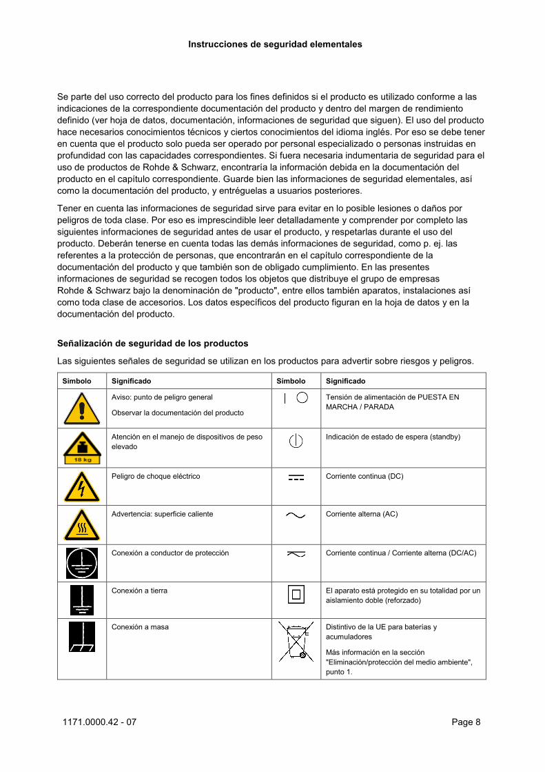
Las siguientes señales de seguridad se utilizan en los productos para advertir sobre riesgos y peligros.
Símbolo Significado Símbolo Significado
Aviso: punto de peligro general
Observar la documentación del producto
Tensión de alimentación de PUESTA EN MARCHA / PARADA
Atención en el manejo de dispositivos de peso elevado
Indicación de estado de espera (standby)
Peligro de choque eléctrico Corriente continua (DC)
Advertencia: superficie caliente Corriente alterna (AC)
Conexión a conductor de protección Corriente continua / Corriente alterna (DC/AC)
Conexión a tierra El aparato está protegido en su totalidad por un aislamiento doble (reforzado)
Conexión a masa Distintivo de la UE para baterías y acumuladores
Más información en la sección "Eliminación/protección del medio ambiente", punto 1.

Instrucciones de seguridad elementales
1171.0000.42 - 07 Page 9
Símbolo Significado Símbolo Significado
Aviso: Cuidado en el manejo de dispositivos sensibles a la electrostática (ESD)
Distintivo de la UE para la eliminación por separado de dispositivos eléctricos y electrónicos
Más información en la sección "Eliminación/protección del medio ambiente", punto 2.
Advertencia: rayo láser
Más información en la sección "Funcionamiento", punto 7.
Palabras de señal y su significado
En la documentación del producto se utilizan las siguientes palabras de señal con el fin de advertir contra riesgos y peligros.
Indica una situación de peligro que, si no se evita, causa lesiones graves o incluso la muerte.
Indica una situación de peligro que, si no se evita, puede causar lesiones graves o incluso la muerte.
Indica una situación de peligro que, si no se evita, puede causar lesiones leves o moderadas.
Indica información que se considera importante, pero no en relación con situaciones de peligro; p. ej., avisos sobre posibles daños materiales. En la documentación del producto se emplea de forma sinónima el término CUIDADO.
Las palabras de señal corresponden a la definición habitual para aplicaciones civiles en el área económica europea. Pueden existir definiciones diferentes a esta definición en otras áreas económicas o en aplicaciones militares. Por eso se deberá tener en cuenta que las palabras de señal aquí descritas sean utilizadas siempre solamente en combinación con la correspondiente documentación del producto y solamente en combinación con el producto correspondiente. La utilización de las palabras de señal en combinación con productos o documentaciones que no les correspondan puede llevar a interpretaciones equivocadas y tener por consecuencia daños en personas u objetos.
Estados operativos y posiciones de funcionamiento
El producto solamente debe ser utilizado según lo indicado por el fabricante respecto a los estados operativos y posiciones de funcionamiento sin que se obstruya la ventilación. Si no se siguen las indicaciones del fabricante, pueden producirse choques eléctricos, incendios y/o lesiones graves con posible consecuencia de muerte. En todos los trabajos deberán ser tenidas en cuenta las normas nacionales y locales de seguridad del trabajo y de prevención de accidentes.
Instrucciones de seguridad elementales
1171.0000.42 - 07 Page 10
1. Si no se convino de otra manera, es para los productos Rohde & Schwarz válido lo que sigue: como posición de funcionamiento se define por principio la posición con el suelo de la caja para abajo, modo de protección IP 2X, uso solamente en estancias interiores, utilización hasta 2000 m sobre el nivel del mar, transporte hasta 4500 m sobre el nivel del mar. Se aplicará una tolerancia de ±10 % sobre el voltaje nominal y de ±5 % sobre la frecuencia nominal. Categoría de sobrecarga eléctrica 2, índice de suciedad 2.
2. No sitúe el producto encima de superficies, vehículos, estantes o mesas, que por sus características de peso o de estabilidad no sean aptos para él. Siga siempre las instrucciones de instalación del fabricante cuando instale y asegure el producto en objetos o estructuras (p. ej. paredes y estantes). Si se realiza la instalación de modo distinto al indicado en la documentación del producto, se pueden causar lesiones o, en determinadas circunstancias, incluso la muerte.
3. No ponga el producto sobre aparatos que generen calor (p. ej. radiadores o calefactores). La temperatura ambiente no debe superar la temperatura máxima especificada en la documentación del producto o en la hoja de datos. En caso de sobrecalentamiento del producto, pueden producirse choques eléctricos, incendios y/o lesiones graves con posible consecuencia de muerte.
Seguridad eléctrica
Si no se siguen (o se siguen de modo insuficiente) las indicaciones del fabricante en cuanto a seguridad eléctrica, pueden producirse choques eléctricos, incendios y/o lesiones graves con posible consecuencia de muerte.
1. Antes de la puesta en marcha del producto se deberá comprobar siempre que la tensión preseleccionada en el producto coincida con la de la red de alimentación eléctrica. Si es necesario modificar el ajuste de tensión, también se deberán cambiar en caso dado los fusibles correspondientes del producto.
2. Los productos de la clase de protección I con alimentación móvil y enchufe individual solamente podrán enchufarse a tomas de corriente con contacto de seguridad y con conductor de protección conectado.
3. Queda prohibida la interrupción intencionada del conductor de protección, tanto en la toma de corriente como en el mismo producto. La interrupción puede tener como consecuencia el riesgo de que el producto sea fuente de choques eléctricos. Si se utilizan cables alargadores o regletas de enchufe, deberá garantizarse la realización de un examen regular de los mismos en cuanto a su estado técnico de seguridad.
4. Si el producto no está equipado con un interruptor para desconectarlo de la red, o bien si el interruptor existente no resulta apropiado para la desconexión de la red, el enchufe del cable de conexión se deberá considerar como un dispositivo de desconexión. El dispositivo de desconexión se debe poder alcanzar fácilmente y debe estar siempre bien accesible. Si, p. ej., el enchufe de conexión a la red es el dispositivo de desconexión, la longitud del cable de conexión no debe superar 3 m). Los interruptores selectores o electrónicos no son aptos para el corte de la red eléctrica. Si se integran productos sin interruptor en bastidores o instalaciones, se deberá colocar el interruptor en el nivel de la instalación.
5. No utilice nunca el producto si está dañado el cable de conexión a red. Compruebe regularmente el correcto estado de los cables de conexión a red. Asegúrese, mediante las medidas de protección y de instalación adecuadas, de que el cable de conexión a red no pueda ser dañado o de que nadie pueda ser dañado por él, p. ej. al tropezar o por un choque eléctrico.
Instrucciones de seguridad elementales
1171.0000.42 - 07 Page 11
6. Solamente está permitido el funcionamiento en redes de alimentación TN/TT aseguradas con fusibles de 16 A como máximo (utilización de fusibles de mayor amperaje solo previa consulta con el grupo de empresas Rohde & Schwarz).
7. Nunca conecte el enchufe en tomas de corriente sucias o llenas de polvo. Introduzca el enchufe por completo y fuertemente en la toma de corriente. La no observación de estas medidas puede provocar chispas, fuego y/o lesiones.
8. No sobrecargue las tomas de corriente, los cables alargadores o las regletas de enchufe ya que esto podría causar fuego o choques eléctricos.
9. En las mediciones en circuitos de corriente con una tensión Ueff > 30 V se deberán tomar las medidas apropiadas para impedir cualquier peligro (p. ej. medios de medición adecuados, seguros, limitación de tensión, corte protector, aislamiento etc.).
10. Para la conexión con dispositivos informáticos como un PC o un ordenador industrial, debe comprobarse que éstos cumplan los estándares IEC60950-1/EN60950-1 o IEC61010-1/EN 61010-1 válidos en cada caso.
11. A menos que esté permitido expresamente, no retire nunca la tapa ni componentes de la carcasa mientras el producto esté en servicio. Esto pone a descubierto los cables y componentes eléctricos y puede causar lesiones, fuego o daños en el producto.
12. Si un producto se instala en un lugar fijo, se deberá primero conectar el conductor de protección fijo con el conductor de protección del producto antes de hacer cualquier otra conexión. La instalación y la conexión deberán ser efectuadas por un electricista especializado.
13. En el caso de dispositivos fijos que no estén provistos de fusibles, interruptor automático ni otros mecanismos de seguridad similares, el circuito de alimentación debe estar protegido de modo que todas las personas que puedan acceder al producto, así como el producto mismo, estén a salvo de posibles daños.
14. Todo producto debe estar protegido contra sobretensión (debida p. ej. a una caída del rayo) mediante los correspondientes sistemas de protección. Si no, el personal que lo utilice quedará expuesto al peligro de choque eléctrico.
15. No debe introducirse en los orificios de la caja del aparato ningún objeto que no esté destinado a ello. Esto puede producir cortocircuitos en el producto y/o puede causar choques eléctricos, fuego o lesiones.
16. Salvo indicación contraria, los productos no están impermeabilizados (ver también el capítulo "Estados operativos y posiciones de funcionamiento", punto 1). Por eso es necesario tomar las medidas necesarias para evitar la entrada de líquidos. En caso contrario, existe peligro de choque eléctrico para el usuario o de daños en el producto, que también pueden redundar en peligro para las personas.
17. No utilice el producto en condiciones en las que pueda producirse o ya se hayan producido condensaciones sobre el producto o en el interior de éste, como p. ej. al desplazarlo de un lugar frío a otro caliente. La entrada de agua aumenta el riesgo de choque eléctrico.
18. Antes de la limpieza, desconecte por completo el producto de la alimentación de tensión (p. ej. red de alimentación o batería). Realice la limpieza de los aparatos con un paño suave, que no se deshilache. No utilice bajo ningún concepto productos de limpieza químicos como alcohol, acetona o diluyentes para lacas nitrocelulósicas.
Instrucciones de seguridad elementales
1171.0000.42 - 07 Page 12
Funcionamiento
1. El uso del producto requiere instrucciones especiales y una alta concentración durante el manejo. Debe asegurarse que las personas que manejen el producto estén a la altura de los requerimientos necesarios en cuanto a aptitudes físicas, psíquicas y emocionales, ya que de otra manera no se pueden excluir lesiones o daños de objetos. El empresario u operador es responsable de seleccionar el personal usuario apto para el manejo del producto.
2. Antes de desplazar o transportar el producto, lea y tenga en cuenta el capítulo "Transporte".
3. Como con todo producto de fabricación industrial no puede quedar excluida en general la posibilidad de que se produzcan alergias provocadas por algunos materiales empleados ―los llamados alérgenos (p. ej. el níquel)―. Si durante el manejo de productos Rohde & Schwarz se producen reacciones alérgicas, como p. ej. irritaciones cutáneas, estornudos continuos, enrojecimiento de la conjuntiva o dificultades respiratorias, debe avisarse inmediatamente a un médico para investigar las causas y evitar cualquier molestia o daño a la salud.
4. Antes de la manipulación mecánica y/o térmica o el desmontaje del producto, debe tenerse en cuenta imprescindiblemente el capítulo "Eliminación/protección del medio ambiente", punto 1.
5. Ciertos productos, como p. ej. las instalaciones de radiocomunicación RF, pueden a causa de su función natural, emitir una radiación electromagnética aumentada. Deben tomarse todas las medidas necesarias para la protección de las mujeres embarazadas. También las personas con marcapasos pueden correr peligro a causa de la radiación electromagnética. El empresario/operador tiene la obligación de evaluar y señalizar las áreas de trabajo en las que exista un riesgo elevado de exposición a radiaciones.
6. Tenga en cuenta que en caso de incendio pueden desprenderse del producto sustancias tóxicas (gases, líquidos etc.) que pueden generar daños a la salud. Por eso, en caso de incendio deben usarse medidas adecuadas, como p. ej. máscaras antigás e indumentaria de protección.
7. Los productos con láser están provistos de indicaciones de advertencia normalizadas en función de la clase de láser del que se trate. Los rayos láser pueden provocar daños de tipo biológico a causa de las propiedades de su radiación y debido a su concentración extrema de potencia electromagnética. En caso de que un producto Rohde & Schwarz contenga un producto láser (p. ej. un lector de CD/DVD), no debe usarse ninguna otra configuración o función aparte de las descritas en la documentación del producto, a fin de evitar lesiones (p. ej. debidas a irradiación láser).
8. Clases de compatibilidad electromagnética (conforme a EN 55011 / CISPR 11; y en analogía con EN 55022 / CISPR 22, EN 55032 / CISPR 32) − Aparato de clase A:
Aparato adecuado para su uso en todos los entornos excepto en los residenciales y en aquellos conectados directamente a una red de distribución de baja tensión que suministra corriente a edificios residenciales. Nota: Los aparatos de clase A están destinados al uso en entornos industriales. Estos aparatos pueden causar perturbaciones radioeléctricas en entornos residenciales debido a posibles perturbaciones guiadas o radiadas. En este caso, se le podrá solicitar al operador que tome las medidas adecuadas para eliminar estas perturbaciones.
− Aparato de clase B: Aparato adecuado para su uso en entornos residenciales, así como en aquellos conectados directamente a una red de distribución de baja tensión que suministra corriente a edificios residenciales.
Instrucciones de seguridad elementales
1171.0000.42 - 07 Page 13
Reparación y mantenimiento
1. El producto solamente debe ser abierto por personal especializado con autorización para ello. Antes de manipular el producto o abrirlo, es obligatorio desconectarlo de la tensión de alimentación, para evitar toda posibilidad de choque eléctrico.
2. El ajuste, el cambio de partes, el mantenimiento y la reparación deberán ser efectuadas solamente por electricistas autorizados por Rohde & Schwarz. Si se reponen partes con importancia para los aspectos de seguridad (p. ej. el enchufe, los transformadores o los fusibles), solamente podrán ser sustituidos por partes originales. Después de cada cambio de partes relevantes para la seguridad deberá realizarse un control de seguridad (control a primera vista, control del conductor de protección, medición de resistencia de aislamiento, medición de la corriente de fuga, control de funcionamiento). Con esto queda garantizada la seguridad del producto.
Baterías y acumuladores o celdas
Si no se siguen (o se siguen de modo insuficiente) las indicaciones en cuanto a las baterías y acumuladores o celdas, pueden producirse explosiones, incendios y/o lesiones graves con posible consecuencia de muerte. El manejo de baterías y acumuladores con electrolitos alcalinos (p. ej. celdas de litio) debe seguir el estándar EN 62133.
1. No deben desmontarse, abrirse ni triturarse las celdas.
2. Las celdas o baterías no deben someterse a calor ni fuego. Debe evitarse el almacenamiento a la luz directa del sol. Las celdas y baterías deben mantenerse limpias y secas. Limpiar las conexiones sucias con un paño seco y limpio.
3. Las celdas o baterías no deben cortocircuitarse. Es peligroso almacenar las celdas o baterías en estuches o cajones en cuyo interior puedan cortocircuitarse por contacto recíproco o por contacto con otros materiales conductores. No deben extraerse las celdas o baterías de sus embalajes originales hasta el momento en que vayan a utilizarse.
4. Las celdas o baterías no deben someterse a impactos mecánicos fuertes indebidos.
5. En caso de falta de estanqueidad de una celda, el líquido vertido no debe entrar en contacto con la piel ni los ojos. Si se produce contacto, lavar con agua abundante la zona afectada y avisar a un médico.
6. En caso de cambio o recarga inadecuados, las celdas o baterías que contienen electrolitos alcalinos (p. ej. las celdas de litio) pueden explotar. Para garantizar la seguridad del producto, las celdas o baterías solo deben ser sustituidas por el tipo Rohde & Schwarz correspondiente (ver lista de recambios).
7. Las baterías y celdas deben reciclarse y no deben tirarse a la basura doméstica. Las baterías o acumuladores que contienen plomo, mercurio o cadmio deben tratarse como residuos especiales. Respete en esta relación las normas nacionales de eliminación y reciclaje.
Transporte
1. El producto puede tener un peso elevado. Por eso es necesario desplazarlo o transportarlo con precaución y, si es necesario, usando un sistema de elevación adecuado (p. ej. una carretilla elevadora), a fin de evitar lesiones en la espalda u otros daños personales.
Instrucciones de seguridad elementales
1171.0000.42 - 07 Page 14
2. Las asas instaladas en los productos sirven solamente de ayuda para el transporte del producto por personas. Por eso no está permitido utilizar las asas para la sujeción en o sobre medios de transporte como p. ej. grúas, carretillas elevadoras de horquilla, carros etc. Es responsabilidad suya fijar los productos de manera segura a los medios de transporte o elevación. Para evitar daños personales o daños en el producto, siga las instrucciones de seguridad del fabricante del medio de transporte o elevación utilizado.
3. Si se utiliza el producto dentro de un vehículo, recae de manera exclusiva en el conductor la responsabilidad de conducir el vehículo de manera segura y adecuada. El fabricante no asumirá ninguna responsabilidad por accidentes o colisiones. No utilice nunca el producto dentro de un vehículo en movimiento si esto pudiera distraer al conductor. Asegure el producto dentro del vehículo debidamente para evitar, en caso de un accidente, lesiones u otra clase de daños.
Eliminación/protección del medio ambiente
1. Los dispositivos marcados contienen una batería o un acumulador que no se debe desechar con los residuos domésticos sin clasificar, sino que debe ser recogido por separado. La eliminación se debe efectuar exclusivamente a través de un punto de recogida apropiado o del servicio de atención al cliente de Rohde & Schwarz.
2. Los dispositivos eléctricos usados no se deben desechar con los residuos domésticos sin clasificar, sino que deben ser recogidos por separado. Rohde & Schwarz GmbH & Co.KG ha elaborado un concepto de eliminación de residuos y asume plenamente los deberes de recogida y eliminación para los fabricantes dentro de la UE. Para desechar el producto de manera respetuosa con el medio ambiente, diríjase a su servicio de atención al cliente de Rohde & Schwarz.
3. Si se trabaja de manera mecánica y/o térmica cualquier producto o componente más allá del funcionamiento previsto, pueden liberarse sustancias peligrosas (polvos con contenido de metales pesados como p. ej. plomo, berilio o níquel). Por eso el producto solo debe ser desmontado por personal especializado con formación adecuada. Un desmontaje inadecuado puede ocasionar daños para la salud. Se deben tener en cuenta las directivas nacionales referentes a la eliminación de residuos.
4. En caso de que durante el trato del producto se formen sustancias peligrosas o combustibles que deban tratarse como residuos especiales (p. ej. refrigerantes o aceites de motor con intervalos de cambio definidos), deben tenerse en cuenta las indicaciones de seguridad del fabricante de dichas sustancias y las normas regionales de eliminación de residuos. Tenga en cuenta también en caso necesario las indicaciones de seguridad especiales contenidas en la documentación del producto. La eliminación incorrecta de sustancias peligrosas o combustibles puede causar daños a la salud o daños al medio ambiente.
Se puede encontrar más información sobre la protección del medio ambiente en la página web de Rohde & Schwarz.

Sehr geehrter Kunde,Sie haben sich für den Kauf eines Rohde & Schwarz Produk-tes entschieden. Sie erhalten damit ein nach modernsten Fer-tigungsmethoden hergestelltes Produkt. Es wurde nach den Regeln unserer Qualitäts- und Umweltmanagementsysteme entwickelt, gefertigt und geprüft. Rohde & Schwarz ist unter ande-rem nach den Managementsys-temen ISO 9001 und ISO 14001 zertifiziert.
Der Umwelt verpflichtet ❙ Energie-effiziente, RoHS-konforme Produkte
❙ Kontinuierliche Weiterentwicklung nachhaltiger Umweltkonzepte
❙ ISO 14001-zertifiziertes Umweltmanagementsystem
Dear customer,You have decided to buy a Rohde & Schwarz product. This product has been manufactured using the most advanced meth-ods. It was developed, manufac-tured and tested in compliance with our quality management and environmental manage-ment systems. Rohde & Schwarz has been certified, for exam-ple, according to the ISO 9001 and ISO 14001 management systems.
Environmental commitment ❙ Energy-efficient products ❙ Continuous improvement in environmental sustainability
❙ ISO 14001-certified environmental management system
Cher client,Vous avez choisi d’acheter un produit Rohde & Schwarz. Vous disposez donc d’un produit fabriqué d’après les méthodes les plus avancées. Le dévelop-pement, la fabrication et les tests de ce produit ont été effec-tués selon nos systèmes de management de qualité et de management environnemental. La société Rohde & Schwarz a été homologuée, entre autres, conformément aux systèmes de management ISO 9001 et ISO 14001.
Engagement écologique ❙ Produits à efficience énergétique
❙ Amélioration continue de la durabilité environnementale
❙ Système de management environnemental certifié selon ISO 14001
Certified Environmental System
ISO 14001
Certified Quality System
ISO 9001Quality management and environmental management
1171
.020
0.11
V 0
5.01
1171020011
ISO-Qualitaets-Zertifikat_1171-0200-11_A4.indd 1 28.09.2012 10:25:08

1171.0200.22-06.00
Customer Support
Technical support – where and when you need it For quick, expert help with any Rohde & Schwarz equipment, contact one of our Customer Support Centers. A team of highly qualified engineers provides telephone support and will work with you to find a solution to your query on any aspect of the operation, programming or applications of Rohde & Schwarz equipment.
Up-to-date information and upgrades To keep your instrument up-to-date and to be informed about new application notes related to your instrument, please send an e-mail to the Customer Support Center stating your instrument and your wish. We will take care that you will get the right information.
Europe, Africa, Middle East Phone +49 89 4129 12345 [email protected]
North America Phone 1-888-TEST-RSA (1-888-837-8772) [email protected]
Latin America Phone +1-410-910-7988 [email protected]
Asia/Pacific Phone +65 65 13 04 88 [email protected]
China Phone +86-800-810-8228 / +86-400-650-5896 [email protected]
ContentsR&S®UPV
3Quick Start Guide 1146.2078.62 ─ 07
Contents1 Contents of the Customer Documentation..........................................5
2 Putting into Operation...........................................................................72.1 Description of the Front View......................................................................................7
2.2 Description of the Rear Panel....................................................................................18
2.3 Putting into Operation................................................................................................23
2.4 Function Check...........................................................................................................31
2.5 Presets.........................................................................................................................31
2.6 Windows XP.................................................................................................................32
2.7 Connecting External Keyboard and Mouse..............................................................33
2.8 Connecting an external monitor................................................................................33
2.9 Installing Options........................................................................................................47
2.10 Connect R&S UPV to a Network (LAN).....................................................................47
2.11 Firmware Update.........................................................................................................64
2.12 Windows XP Recovery and Backup..........................................................................65
3 Getting Started.....................................................................................713.1 Introduction - Getting Started....................................................................................71
3.2 Important Information for Measurements.................................................................72
3.3 Brief Introduction to Operation..................................................................................74
3.4 Introduction to Instrument Operation Using Examples..........................................87
3.5 Loading predefined instrument setups...................................................................107
4 Manual Operation...............................................................................1094.1 Introduction - Manual Operation..............................................................................109
4.2 Functional Division of the Audio Analyzer.............................................................110
4.3 General Information on Operation...........................................................................117
4.4 The Display................................................................................................................120
4.5 Panels.........................................................................................................................127
4.6 Settings on the Audio Analyzer...............................................................................133
4.7 Settings in the Panels...............................................................................................133
4.8 Measurement Displays.............................................................................................146
4.9 Settings in the Menu Bar..........................................................................................175
ContentsR&S®UPV
4Quick Start Guide 1146.2078.62 ─ 07
4.10 Settings on the Toolbar............................................................................................181
4.11 Settings in the Operating System............................................................................182
4.12 Auxiliaries Panel.......................................................................................................182
4.13 Rapid Deactivation of Outputs.................................................................................185
4.14 Help System...............................................................................................................185
4.15 File Management.......................................................................................................188
4.16 Manual Remote Operation........................................................................................192
4.17 Units...........................................................................................................................194
4.18 Overview of Keys......................................................................................................200
4.19 Overview of Panels and Measurement Displays (Graphical Windows)...............204
4.20 Overview of Status Messages..................................................................................207
Index....................................................................................................209
Contents of the Customer DocumentationR&S®UPV
5Quick Start Guide 1146.2078.62 ─ 07
1 Contents of the Customer DocumentationThe customer documentation for the R&S UPV consists of:
● Quick Start Guide● Operating manual for the base unit and the options● Service manual (English only)● Context-sensitive online help● Release Notes
The respective current version of the documentation is always available on the Internet(www.rohde-schwarz.com/downloads/manuals/upv.html).
Quick Start Guide
The printed quick start guide is part of the equipment supplied of the device. It containsinformation about the technical properties of the device, its commissioning, the funda-mental operating steps and controls. The quick start guide is divided into three chapters:
● Commissioning● Getting Started● Manual Operation
Operating manual
The operating manual is located on the supplied CD-ROM. In addition to the chapters ofthe quick start guide, it contains the description of all device functions and the remotecontrol of the device. Furthermore, it features notes for the preventive maintenance ofthe R&S UPV and for locating errors based on the warnings and error messages issuedby the device. It is divided into the following chapters:
● Putting into Operation● Getting Started● Manual Operation● Instrument Function● Remote Control - Fundamentals● Remote Control - Commands● Maintenance and Instrument Interfaces
Service Manual
The service manual in English is located on the supplied CD-ROM. It contains all thenecessary information to maintain the R&S UPV by replacing modules and to expand itsfunctionality by installing options. The service manual is divided into the following chap-ters:
● Performance Test● Adjustment● Repair
Contents of the Customer DocumentationR&S®UPV
6Quick Start Guide 1146.2078.62 ─ 07
● Firmware Update / Installing Options● Documents
Context-sensitive online help
The context-sensitive online help provides support for the operation of the R&S UPV andits options – it describes the manual operation and the remote control. The online help isinstalled on the R&S UPV by default and is also supplied as external .chm file on thedocumentation CD-ROM.
Release Notes
The release notes describe the installation of the firmware, new and improved functions,problems solved and last-minute changes to the documentation. The corresponding firm-ware version can be seen on the cover sheet of the release notes. The current versionof the release notes is available on the Internet (www.rohde-schwarz.com/downloads/firmware/upv.html).

Putting into OperationR&S®UPV
7Quick Start Guide 1146.2078.62 ─ 07
2 Putting into OperationThe R&S UPV audio analyzer is available in two models. The R&S UPV standard modeland an R&S 66 model specifically tailored to system application UPVthat is offered with-out display, without front panel controls and without CD/DVD drive. Except for the oper-ation via front panel, the R&S UPV66 variant is largely identical to the standard modelwith respect to functionality. This manual therefore describes both instruments in parallel,and any differences are indicated at the appropriate points in the text.
This chapter describes the controls and ports of the R&S audio analyzer UPV based onthe front and rear view and shows how to put the instrument into operation. It alsodescribes the connection of peripherals such as printer, keyboard, mouse and monitor.Specifications for the interfaces can be found in the data sheet.
The introduction to chapter 3.1, "Introduction - Getting Started", on page 71 providesan overview of the functions and the operating concept of the audio analyzer. Detailedoperating instructions and an overview of the menus are provided in chapter 4.1, "Intro-duction - Manual Operation", on page 109.
The CD-ROM contains the entire manual complete with the other chapters in printablePDF format: The individual menus and functions of the instrument including the associ-ated remote-control commands are explained in detail in the reference section of chapter"Device Functions." Basic information on remote control of the instrument is provided inthe chapters "Remote Control - Fundamentals" and "Remote Control - Commands". Adetailed description of the instrument interfaces can be found in the chapter "Maintenanceand Interfaces".
The audio analyzer is equipped with the Windows XP® operating system. No specialknowledge of the operating system used is required for operating the instrument.Basic PC knowledge, such as what a file, a directory, etc. is, or how data are transferredusing Windows Explorer ® are assumed and, therefore, are not discussed in any detail.The R&S UPV audio analyzer can be fully operated via the controls on the front panel. Itis, however, also possible to operate the instrument using an external keyboard andmouse. Operation follows the same basic rules which apply to other Windows programsin use today. It is also assumed that users are familiar with these basic rules. This infor-mation is therefore not specified in detail here.The R&S UPV66 model does not feature a front panel keyboard and has no display orCD/DVD drive; but similar to the R&S UPV standard model, it can be operated by meansof a keyboard or mouse after an external monitor is connected.
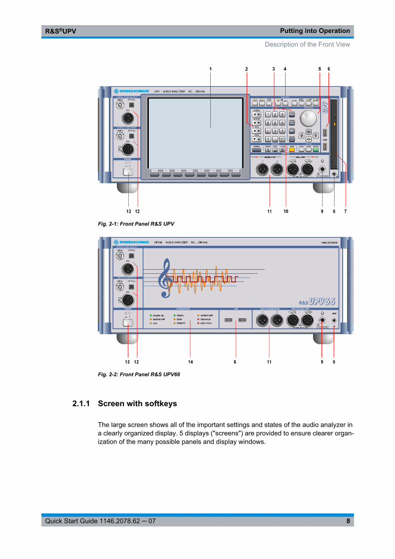
2.1 Description of the Front View
This section provides an overview of the control elements and connectors on the front ofthe R&S UPV / R&S UPV66
Description of the Front View
Putting into OperationR&S®UPV
8Quick Start Guide 1146.2078.62 ─ 07
Fig. 2-1: Front Panel R&S UPV
Fig. 2-2: Front Panel R&S UPV66
2.1.1 Screen with softkeys
The large screen shows all of the important settings and states of the audio analyzer ina clearly organized display. 5 displays ("screens") are provided to ensure clearer organ-ization of the many possible panels and display windows.
Description of the Front View
Putting into OperationR&S®UPV
9Quick Start Guide 1146.2078.62 ─ 07
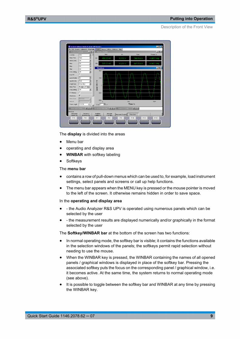
The display is divided into the areas
● Menu bar● operating and display area● WINBAR with softkey labeling● Softkeys
The menu bar
● contains a row of pull-down menus which can be used to, for example, load instrumentsettings, select panels and screens or call up help functions.
● The menu bar appears when the MENU key is pressed or the mouse pointer is movedto the left of the screen. It otherwise remains hidden in order to save space.
In the operating and display area
● - the Audio Analyzer R&S UPV is operated using numerous panels which can beselected by the user
● - the measurement results are displayed numerically and/or graphically in the formatselected by the user
The Softkey/WINBAR bar at the bottom of the screen has two functions:
● In normal operating mode, the softkey bar is visible; it contains the functions availablein the selection windows of the panels; the softkeys permit rapid selection withoutneeding to use the mouse.
● When the WINBAR key is pressed, the WINBAR containing the names of all openedpanels / graphical windows is displayed in place of the softkey bar. Pressing theassociated softkey puts the focus on the corresponding panel / graphical window, i.e.it becomes active. At the same time, the system returns to normal operating mode(see above).
● It is possible to toggle between the softkey bar and WINBAR at any time by pressingthe WINBAR key.
Description of the Front View
Putting into OperationR&S®UPV
10Quick Start Guide 1146.2078.62 ─ 07
The Softkeys
● corresponds to the label on the softkey bar and WINBAR. The softkeys can also beoperated using the function keys on the external keyboard or by clicking the associ-ated button.
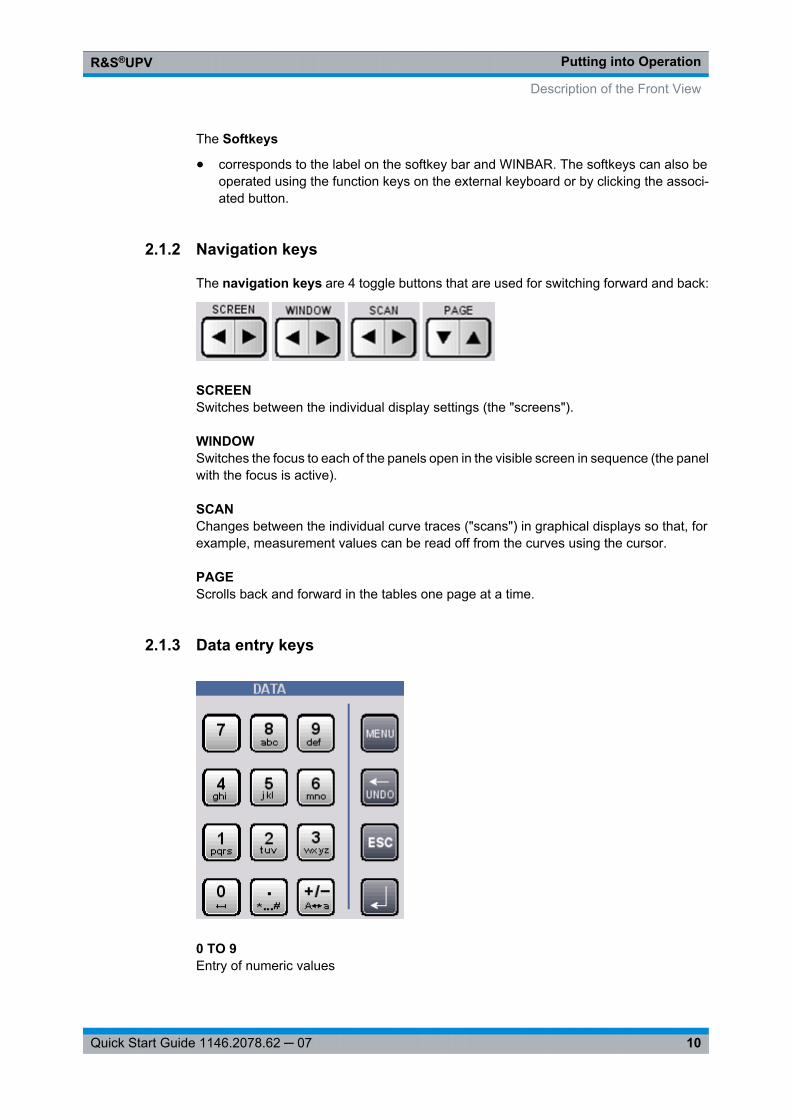
2.1.2 Navigation keys
The navigation keys are 4 toggle buttons that are used for switching forward and back:
SCREENSwitches between the individual display settings (the "screens").
WINDOWSwitches the focus to each of the panels open in the visible screen in sequence (the panelwith the focus is active).
SCANChanges between the individual curve traces ("scans") in graphical displays so that, forexample, measurement values can be read off from the curves using the cursor.
PAGEScrolls back and forward in the tables one page at a time.
2.1.3 Data entry keys
0 TO 9Entry of numeric values
Description of the Front View
Putting into OperationR&S®UPV
11Quick Start Guide 1146.2078.62 ─ 07
.Entry of decimal point
+/–Entry of sign
abc Entry of letters for file names and/or directory names in the file selector in the mobilephone method (see chapter 4.15.2, "Integrated File Select Window", on page 189), pro-vided that it appears in the R&S UPV style. The appearance of the file selector can bechanged via the Config panel under the "File Selector" heading. To switch on the R&SUPV style, the "Win Style" check mark must not be set (see chapter 4.15.1, "Selectingthe File Select Window", on page 189).
BLANKEntry of a space
* TO #Entry of special characters
A <---> aSwitching between uppercase and lowercase letters
MENUDisplays the menu bar on the screen
<--- / UNDODeletes the character to the left of the cursor
Undoes the action last performed
ESCCloses the open window; the old value or parameter is retained
ENTERCompletes the data entry; the new value is adopted
Confirms (OK) and closes open entry windows
Pressing the rotary knob has the same effect
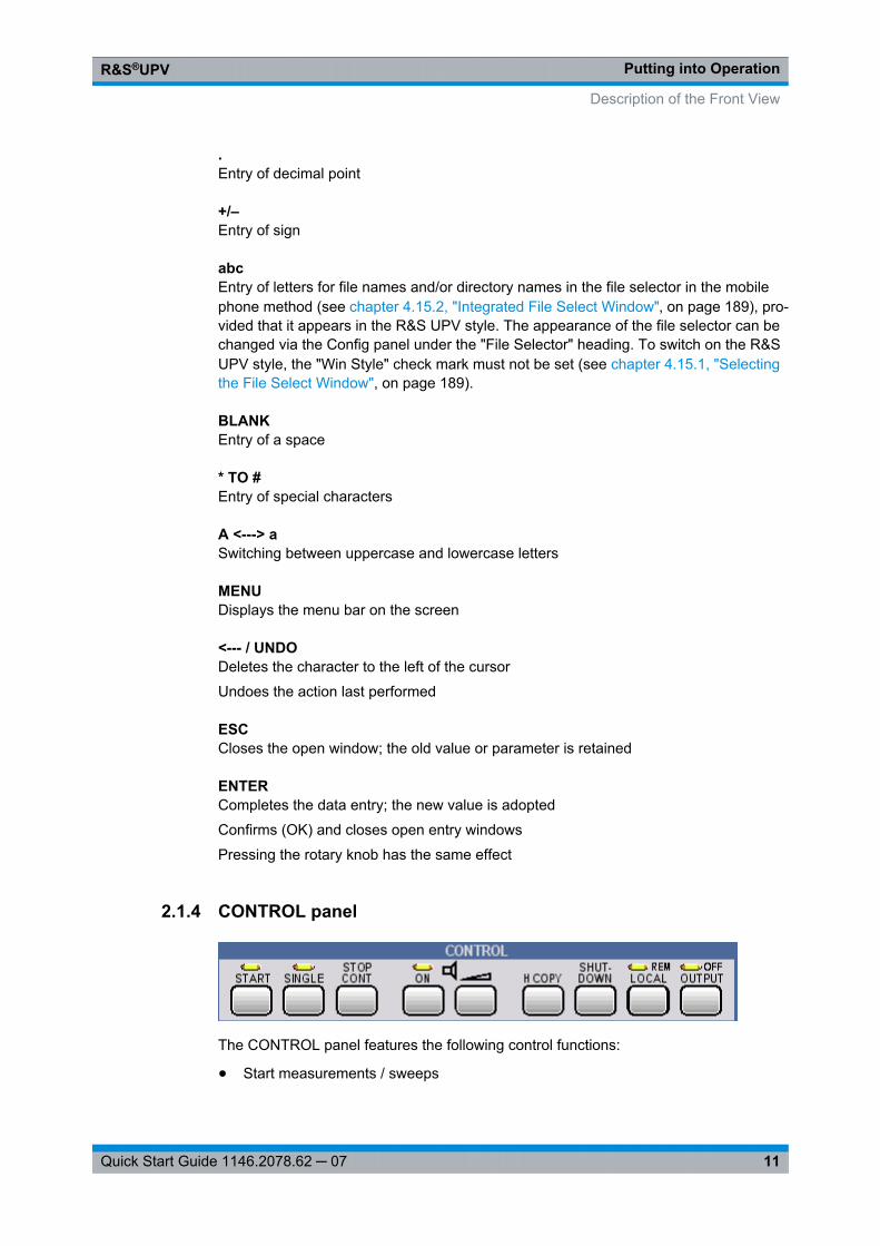
2.1.4 CONTROL panel
The CONTROL panel features the following control functions:
● Start measurements / sweeps
Description of the Front View
Putting into OperationR&S®UPV
12Quick Start Guide 1146.2078.62 ─ 07
● Adjust the loudspeaker● Print the screen contents● Shut down the operating system● Switch between remote / manual operation● Switch off outputs
STARTStarts continuous measurements and sweeps (the LED is on); resets Min/Max values forbar graph displays, averaging for measurement results, and limit overshoots
SINGLEStarts a single measurement or a single sweep (the LED is on during execution)
STOP/CONTMeasurement / sweep is stopped or continued (toggle function)
ONSwitches the loudspeaker or connected headphones on and off (toggle function)
VOLUMEOpens a window for adjusting the audio monitoring volume
H COPYDepending on the settings under Utilities, printout of the screen contents on the connec-ted printer is started or the screen contents are stored in a file
SHUTDOWNStores the current settings on the hard disk and then shuts down the Windows operatingsystem
LOCALSwitches from remote control to manual operation (the LED is on with remote control)
OUTPUTSwitches all outputs of the measuring instrument off or on again (the LED is on when theoutputs are switched off)
Description of the Front View
Putting into OperationR&S®UPV
13Quick Start Guide 1146.2078.62 ─ 07
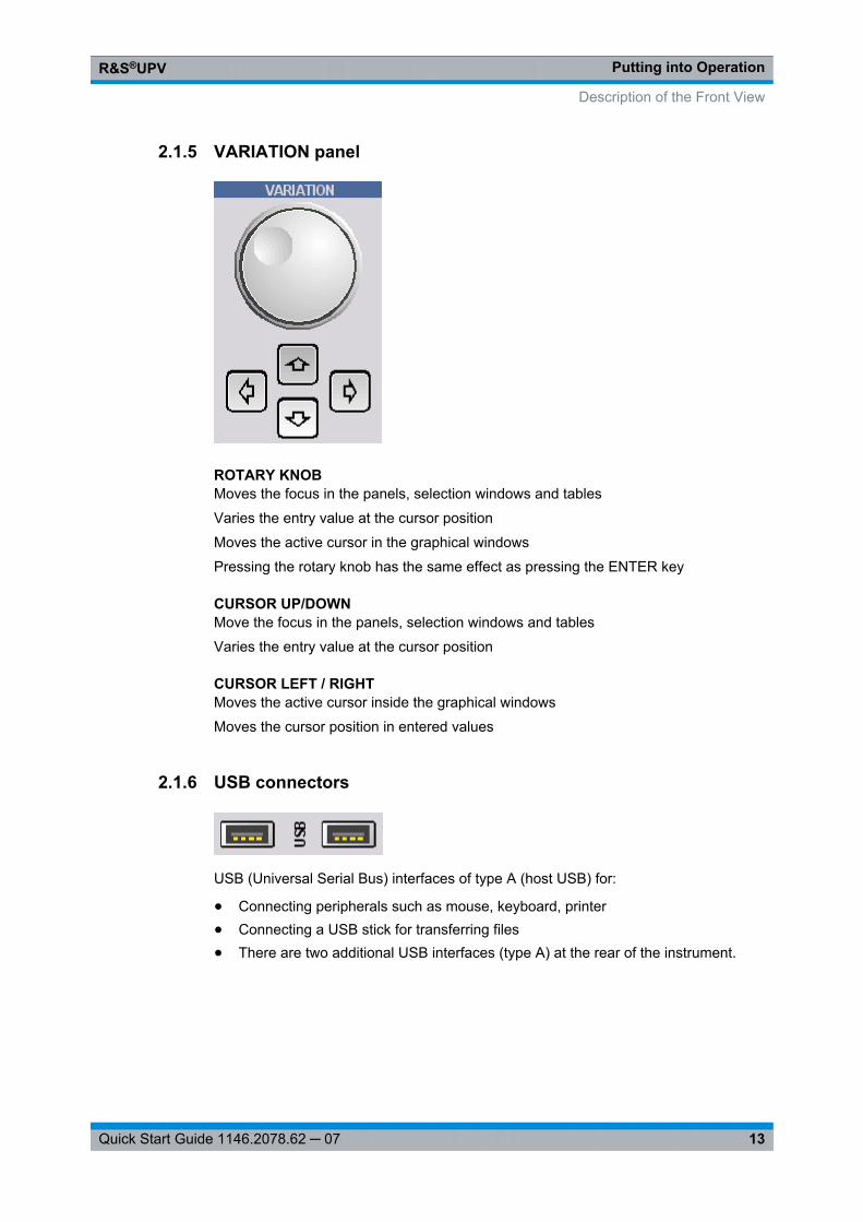
2.1.5 VARIATION panel
ROTARY KNOBMoves the focus in the panels, selection windows and tables
Varies the entry value at the cursor position
Moves the active cursor in the graphical windows
Pressing the rotary knob has the same effect as pressing the ENTER key
CURSOR UP/DOWNMove the focus in the panels, selection windows and tables
Varies the entry value at the cursor position
CURSOR LEFT / RIGHTMoves the active cursor inside the graphical windows
Moves the cursor position in entered values
2.1.6 USB connectors
USB (Universal Serial Bus) interfaces of type A (host USB) for:
● Connecting peripherals such as mouse, keyboard, printer● Connecting a USB stick for transferring files● There are two additional USB interfaces (type A) at the rear of the instrument.
Description of the Front View

Putting into OperationR&S®UPV
14Quick Start Guide 1146.2078.62 ─ 07
2.1.7 CD/DVD Combo drive
The integrated combined CD/DVD drive is used to
● install software updates on the R&S UPV● install sequence programs and macros● import data and instrument settings from other R&S UPVs● store data on a CD
2.1.8 Ground socket
Ground socket that is connected with the instrument housing.
2.1.9 Headphones connector
Connection of headphones for audio monitoring of the analysis or generator signal
2.1.10 WINDOW / SETUP panel
WINBARThe WINBAR is used to toggle between the softkey bar and WINBAR at any time:
● In normal operating mode, the softkey bar is visible; it contains the functions availablein the selection windows of the panels; the softkeys permit rapid selection withoutneeding to use the mouse.
Description of the Front View
Putting into OperationR&S®UPV
15Quick Start Guide 1146.2078.62 ─ 07
● When the WINBAR key is pressed, the WINBAR containing the names of all openedpanels or graphical windows is displayed in place of the softkey bar. Pressing theassociated softkey puts the focus on the corresponding panel or graphical window,i.e. it becomes active. At the same time, the system returns to normal operating mode(see above).
MODIFYOpens a selection of functions on the softkey bar; these functions can be used in con-junction with the rotary knob to move or resize the active panel or graphical window
HIDEMinimizes ("hides") the active panel or graphical window
CLOSECloses the active panel or graphical window
HELPPressing this key displays a context-sensitive help text
SAVEOpens a window for storing instrument settings
LOADOpens a window for loading predefined instrument settings
PRESETLoads the factory settings of the instrument
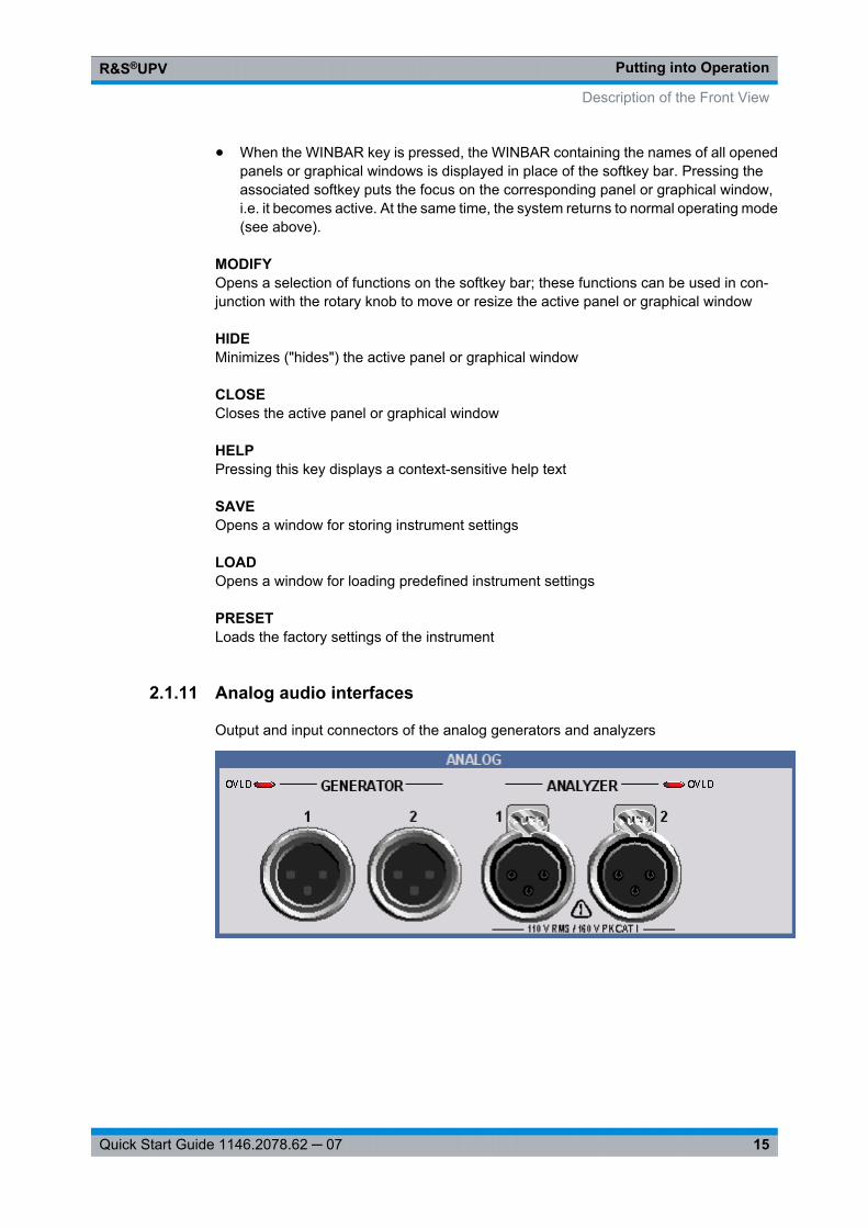
2.1.11 Analog audio interfaces
Output and input connectors of the analog generators and analyzers
Description of the Front View
Putting into OperationR&S®UPV
16Quick Start Guide 1146.2078.62 ─ 07
Possible instrument damage due to incorrect input voltagesThe instrument complies with measuring category I; make sure that the input voltage atthe connectors of the analog analyzers does not exceed 110 V (rms, sinusoidal) and160 V (peak value).Do not use the instrument in measuring categories II, III and IV.Explanation: Measuring circuits as defined in section 6.7.4 of EN61010-1: Measuringcategory I is intended for measurements on circuits which are not connected to the high-voltage current system.Meaning of the LEDs: Generator OVLD: Generator is overloaded. Analyzer OVLD: Thelow-impedance input resistors (300 Ohm or 600 Ohm) are overloaded and have beenswitched off.The output stage can be damaged by an unacceptably high external signal feed. Thefrontend can be damaged by an unacceptably high external signal feed from a low-impe-dance source in the analyzer. Injury to persons is to be excluded for external signal feedor excessive input voltage.
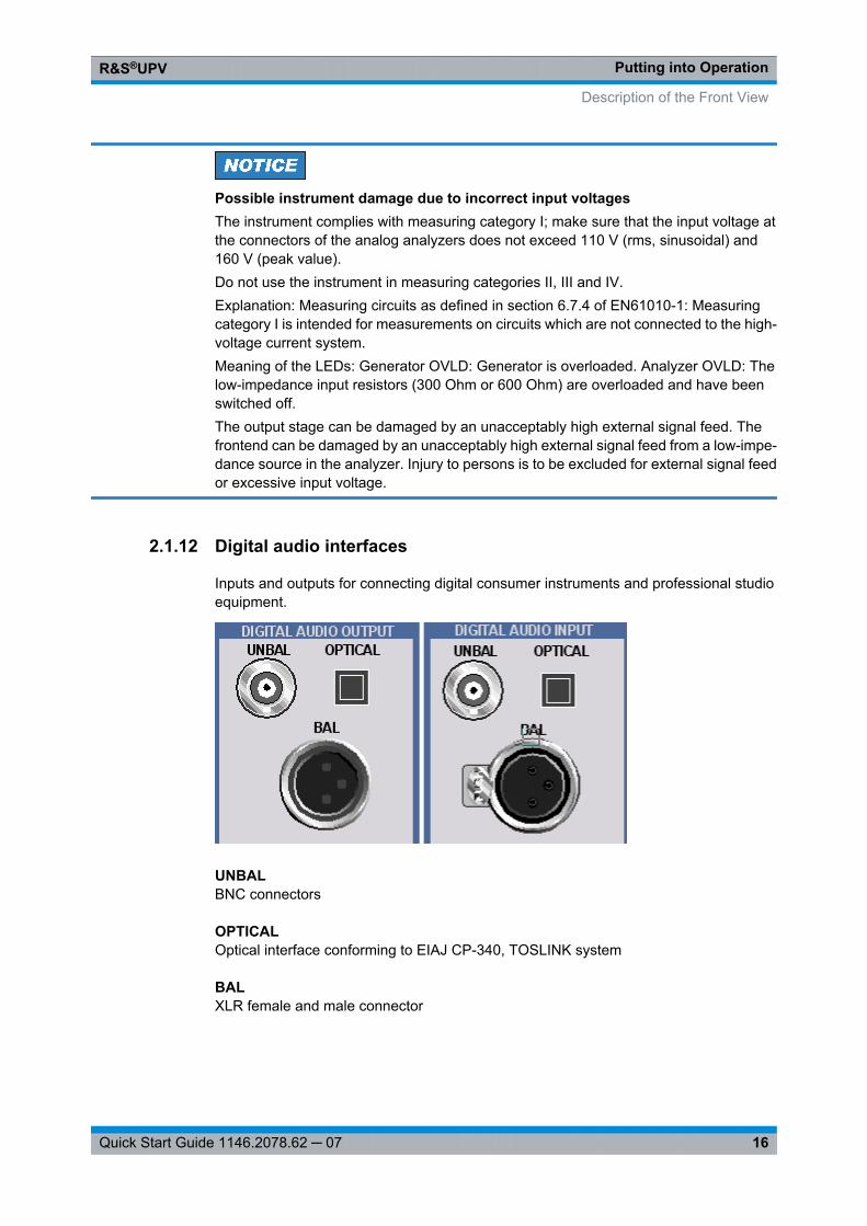
2.1.12 Digital audio interfaces
Inputs and outputs for connecting digital consumer instruments and professional studioequipment.
UNBALBNC connectors
OPTICALOptical interface conforming to EIAJ CP-340, TOSLINK system
BALXLR female and male connector
Description of the Front View
Putting into OperationR&S®UPV
17Quick Start Guide 1146.2078.62 ─ 07
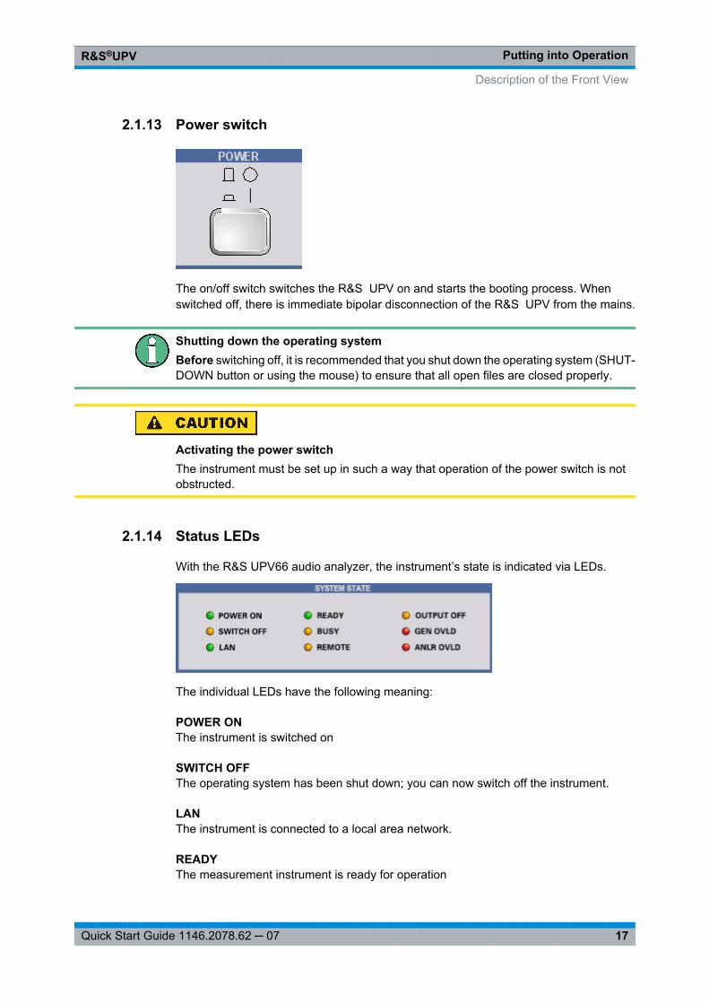
2.1.13 Power switch
The on/off switch switches the R&S UPV on and starts the booting process. Whenswitched off, there is immediate bipolar disconnection of the R&S UPV from the mains.
Shutting down the operating systemBefore switching off, it is recommended that you shut down the operating system (SHUT-DOWN button or using the mouse) to ensure that all open files are closed properly.
Activating the power switchThe instrument must be set up in such a way that operation of the power switch is notobstructed.
2.1.14 Status LEDs
With the R&S UPV66 audio analyzer, the instrument’s state is indicated via LEDs.
The individual LEDs have the following meaning:
POWER ONThe instrument is switched on
SWITCH OFFThe operating system has been shut down; you can now switch off the instrument.
LANThe instrument is connected to a local area network.
READYThe measurement instrument is ready for operation
Description of the Front View
Putting into OperationR&S®UPV
18Quick Start Guide 1146.2078.62 ─ 07
BUSYLights as long as a measurement is running
REMOTEThe instrument is in remote operation
OUTPUT OFFAll outputs of the R&S UPV66 audio analyzer are switched off
GEN OVLDGenerator is overloaded
ANLR OVLDThe low-impedance input resistors (300 Ohm or 600 Ohm) are overloaded and have beenswitched off.
UNBALBNC connectors
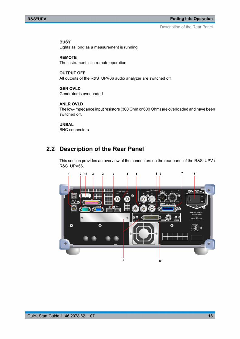
2.2 Description of the Rear Panel
This section provides an overview of the connectors on the rear panel of the R&S UPV /R&S UPV66.
Description of the Rear Panel
Putting into OperationR&S®UPV
19Quick Start Guide 1146.2078.62 ─ 07
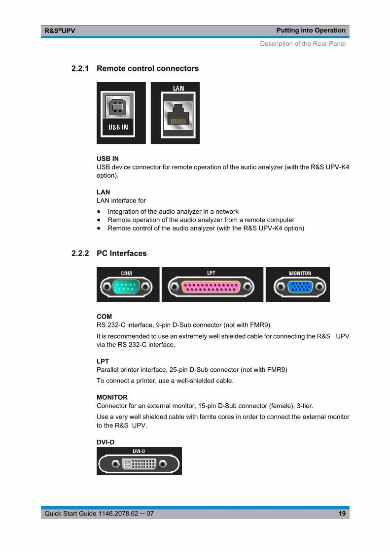
2.2.1 Remote control connectors
USB INUSB device connector for remote operation of the audio analyzer (with the R&S UPV-K4option).
LANLAN interface for
● Integration of the audio analyzer in a network● Remote operation of the audio analyzer from a remote computer● Remote control of the audio analyzer (with the R&S UPV-K4 option)
2.2.2 PC Interfaces
COMRS 232-C interface, 9-pin D-Sub connector (not with FMR9)
It is recommended to use an extremely well shielded cable for connecting the R&S UPVvia the RS 232-C interface.
LPTParallel printer interface, 25-pin D-Sub connector (not with FMR9)
To connect a printer, use a well-shielded cable.
MONITORConnector for an external monitor, 15-pin D-Sub connector (female), 3-tier.
Use a very well shielded cable with ferrite cores in order to connect the external monitorto the R&S UPV.
DVI-D
Description of the Rear Panel
Putting into OperationR&S®UPV
20Quick Start Guide 1146.2078.62 ─ 07
Connector for an external monitor, 24-pin D-Sub connector, 3-tier (only with FMR9)
Use a very well shielded cable with ferrite cores in order to connect the external monitorto the R&S UPV.
2.2.3 USB connectors
USB (Universal Serial Bus) interfaces of type A (host USB).
● Connecting peripherals such as mouse, keyboard, printer● Connecting a USB stick for transferring files
There are additional USB interfaces on the front of the instrument.
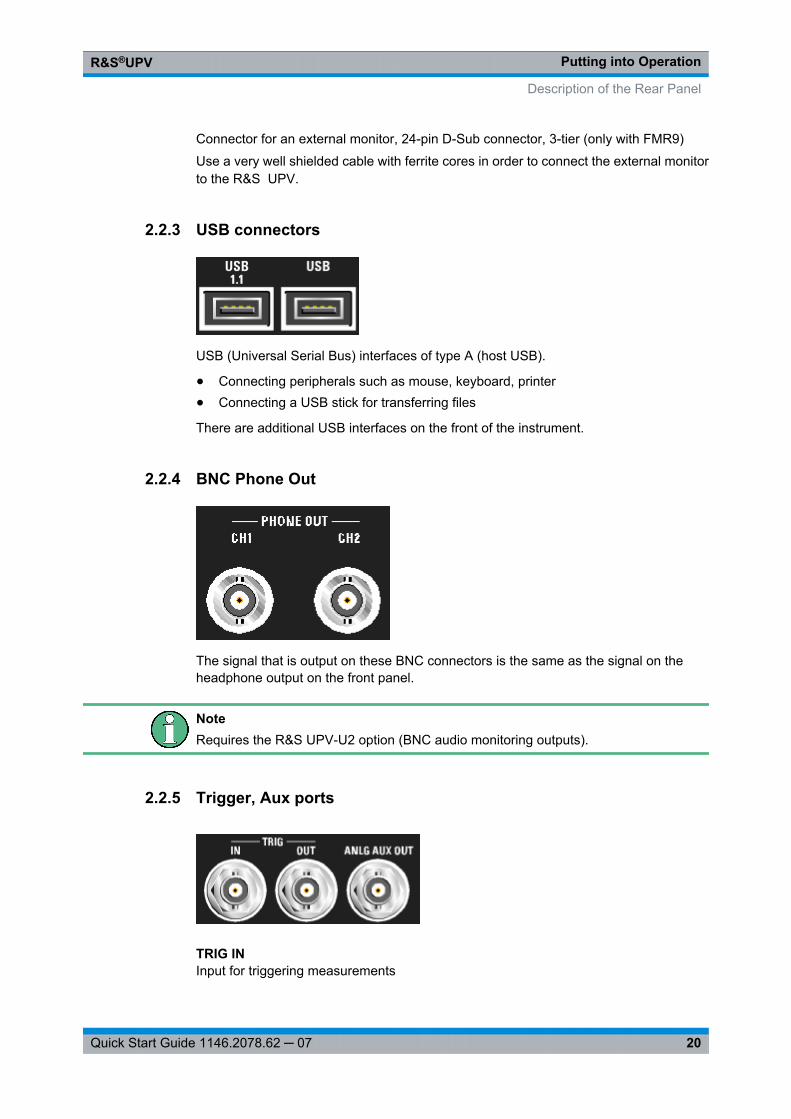
2.2.4 BNC Phone Out
The signal that is output on these BNC connectors is the same as the signal on theheadphone output on the front panel.
NoteRequires the R&S UPV-U2 option (BNC audio monitoring outputs).
2.2.5 Trigger, Aux ports
TRIG INInput for triggering measurements
Description of the Rear Panel

Putting into OperationR&S®UPV
21Quick Start Guide 1146.2078.62 ─ 07
TRIG OUTTrigger output and clock output
ANLG AUX OUTAdditional analog output for special applications
● DC output, e.g. for supplying power to hearing aids● Output for the analog generator signal via an integrated amplifier for the direct actua-
tion of small loudspeakers
2.2.6 Digital synchronization and expansion interfaces
Inputs and outputs for reference and sync signals for the R&S UPV-B2 option (digitalaudio interfaces)
NoteThese interfaces are only available in conjunction with the R&S UPV-B2 option.
SYNC INSynchronization input for word-clock signals
SYNC OUTOutput for synchronizing digital peripherals to the word clock or biphase clock of the R&S UPV
AUX INInput for a digital audio reference signal (DARS)
AUX OUTOutput for a digital audio reference signal (DARS) generated by the R&S UPV
2.2.7 IEC/IEEE-bus connector
Description of the Rear Panel
Putting into OperationR&S®UPV
22Quick Start Guide 1146.2078.62 ─ 07
IEC bus connector (IEC 625/IEEE 488) for remote control of the R&S UPV
NoteRequires the R&S UPV-K4 option (remote control).
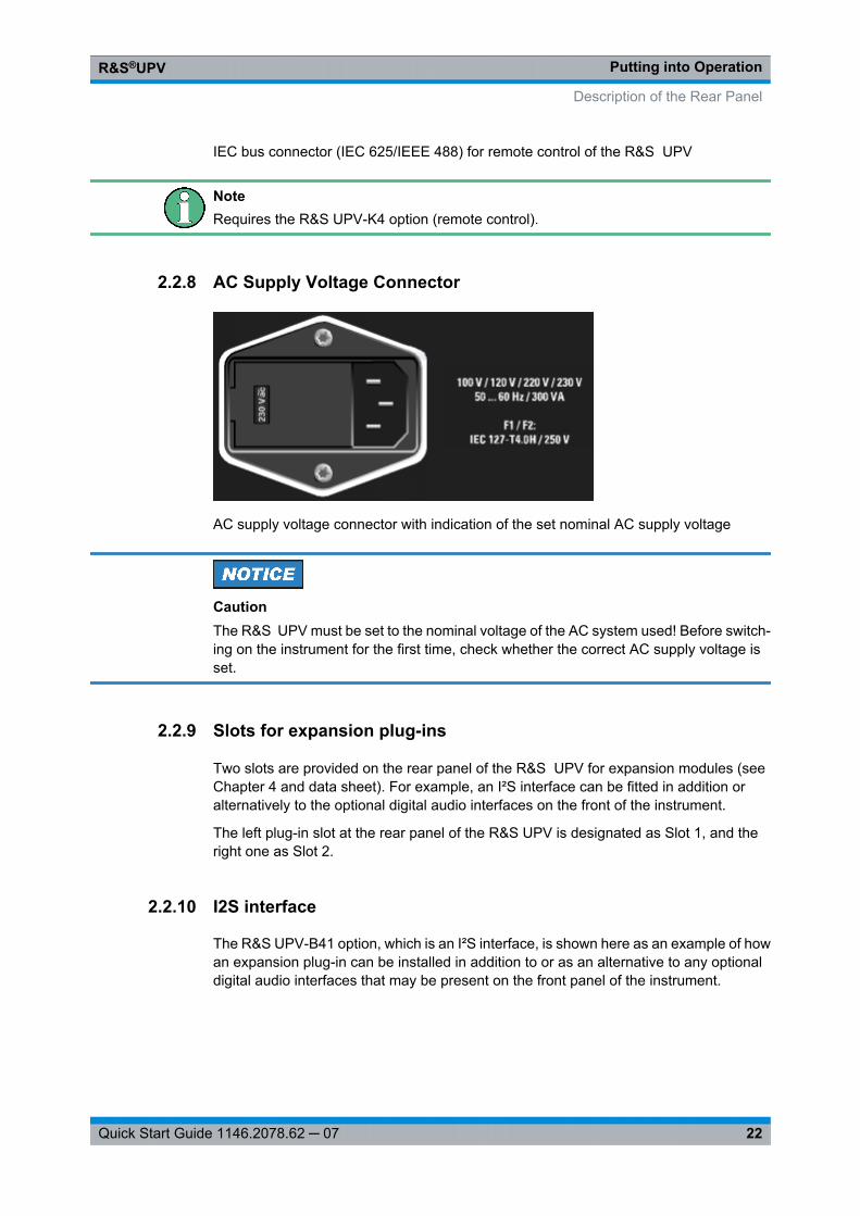
2.2.8 AC Supply Voltage Connector
AC supply voltage connector with indication of the set nominal AC supply voltage
CautionThe R&S UPV must be set to the nominal voltage of the AC system used! Before switch-ing on the instrument for the first time, check whether the correct AC supply voltage isset.
2.2.9 Slots for expansion plug-ins
Two slots are provided on the rear panel of the R&S UPV for expansion modules (seeChapter 4 and data sheet). For example, an I²S interface can be fitted in addition oralternatively to the optional digital audio interfaces on the front of the instrument.
The left plug-in slot at the rear panel of the R&S UPV is designated as Slot 1, and theright one as Slot 2.
2.2.10 I2S interface
The R&S UPV-B41 option, which is an I²S interface, is shown here as an example of howan expansion plug-in can be installed in addition to or as an alternative to any optionaldigital audio interfaces that may be present on the front panel of the instrument.
Description of the Rear Panel
Putting into OperationR&S®UPV
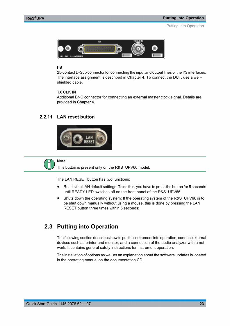
23Quick Start Guide 1146.2078.62 ─ 07
I²S25-contact D-Sub connector for connecting the input and output lines of the I²S interfaces.The interface assignment is described in Chapter 4. To connect the DUT, use a well-shielded cable.
TX CLK INAdditional BNC connector for connecting an external master clock signal. Details areprovided in Chapter 4.
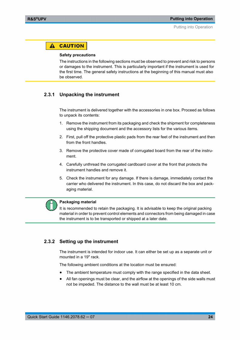
2.2.11 LAN reset button
NoteThis button is present only on the R&S UPV66 model.
The LAN RESET button has two functions:
● Resets the LAN default settings: To do this, you have to press the button for 5 secondsuntil READY LED switches off on the front panel of the R&S UPV66.
● Shuts down the operating system: If the operating system of the R&S UPV66 is tobe shut down manually without using a mouse, this is done by pressing the LANRESET button three times within 5 seconds;
2.3 Putting into Operation
The following section describes how to put the instrument into operation, connect externaldevices such as printer and monitor, and a connection of the audio analyzer with a net-work. It contains general safety instructions for instrument operation.
The installation of options as well as an explanation about the software updates is locatedin the operating manual on the documentation CD.
Putting into Operation
Putting into OperationR&S®UPV
24Quick Start Guide 1146.2078.62 ─ 07
Safety precautionsThe instructions in the following sections must be observed to prevent and risk to personsor damages to the instrument. This is particularly important if the instrument is used forthe first time. The general safety instructions at the beginning of this manual must alsobe observed.
2.3.1 Unpacking the instrument
The instrument is delivered together with the accessories in one box. Proceed as followsto unpack its contents:
1. Remove the instrument from its packaging and check the shipment for completenessusing the shipping document and the accessory lists for the various items.
2. First, pull off the protective plastic pads from the rear feet of the instrument and thenfrom the front handles.
3. Remove the protective cover made of corrugated board from the rear of the instru-ment.
4. Carefully unthread the corrugated cardboard cover at the front that protects theinstrument handles and remove it.
5. Check the instrument for any damage. If there is damage, immediately contact thecarrier who delivered the instrument. In this case, do not discard the box and pack-aging material.
Packaging materialIt is recommended to retain the packaging. It is advisable to keep the original packingmaterial in order to prevent control elements and connectors from being damaged in casethe instrument is to be transported or shipped at a later date.
2.3.2 Setting up the instrument
The instrument is intended for indoor use. It can either be set up as a separate unit ormounted in a 19" rack.
The following ambient conditions at the location must be ensured:
● The ambient temperature must comply with the range specified in the data sheet.● All fan openings must be clear, and the airflow at the openings of the side walls must
not be impeded. The distance to the wall must be at least 10 cm.
Putting into Operation
Putting into OperationR&S®UPV
25Quick Start Guide 1146.2078.62 ─ 07
Possible damage from electrostatic discharge
Electrical discharges can damage components of the instrument or a connected deviceunder test.For this reason, the instrument may be operated only at a workplace that is protectedagainst electrostatic discharge.The following methods can be used separately or in combination to protect against elec-trostatic discharges:● Protective wristband with ground conductor● Conductive floor covering with heel band
EMI suppressionTo suppress electromagnetic interference (EMI), the instrument may be operated only ifit is closed and all covers are in place. The EMC class is listed on the data sheet.The following conditions must be maintained to avoid interferences:● Use suitable double-shielded cables.● Do not use any USB cables that are longer than 1 m.● Use only USB devices that adhere to the permissible EMC values.● Terminate the outputs and cables with 50 Ω.● Use only the cables R&S UP-Z2, R&S UP-Z3 and R&S UP-Z4 for the digital interfa-
ces.
2.3.2.1 Separate installation
The R&S UPV can be set up on a level surface in horizontal position and with unfoldedinstrument feet.
Putting into Operation
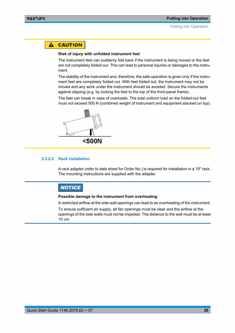
Putting into OperationR&S®UPV
26Quick Start Guide 1146.2078.62 ─ 07
Risk of injury with unfolded instrument feetThe instrument feet can suddenly fold back if the instrument is being moved or the feetare not completely folded out. This can lead to personal injuries or damages to the instru-ment.The stability of the instrument and, therefore, the safe operation is given only if the instru-ment feet are completely folded out. With feet folded out, the instrument may not bemoved and any work under the instrument should be avoided. Secure the instrumentsagainst slipping (e.g. by locking the feet to the top of the front-panel frame).The feet can break in case of overloads. The total uniform load on the folded-out feetmust not exceed 500 N (combined weight of instrument and equipment stacked on top).
2.3.2.2 Rack installation
A rack adapter (refer to data sheet for Order No.) is required for installation in a 19" rack.The mounting instructions are supplied with the adapter.
Possible damage to the instrument from overheatingA restricted airflow at the side wall openings can lead to an overheating of the instrument.To ensure sufficient air supply, all fan openings must be clear and the airflow at theopenings of the side walls must not be impeded. The distance to the wall must be at least10 cm.
Putting into Operation
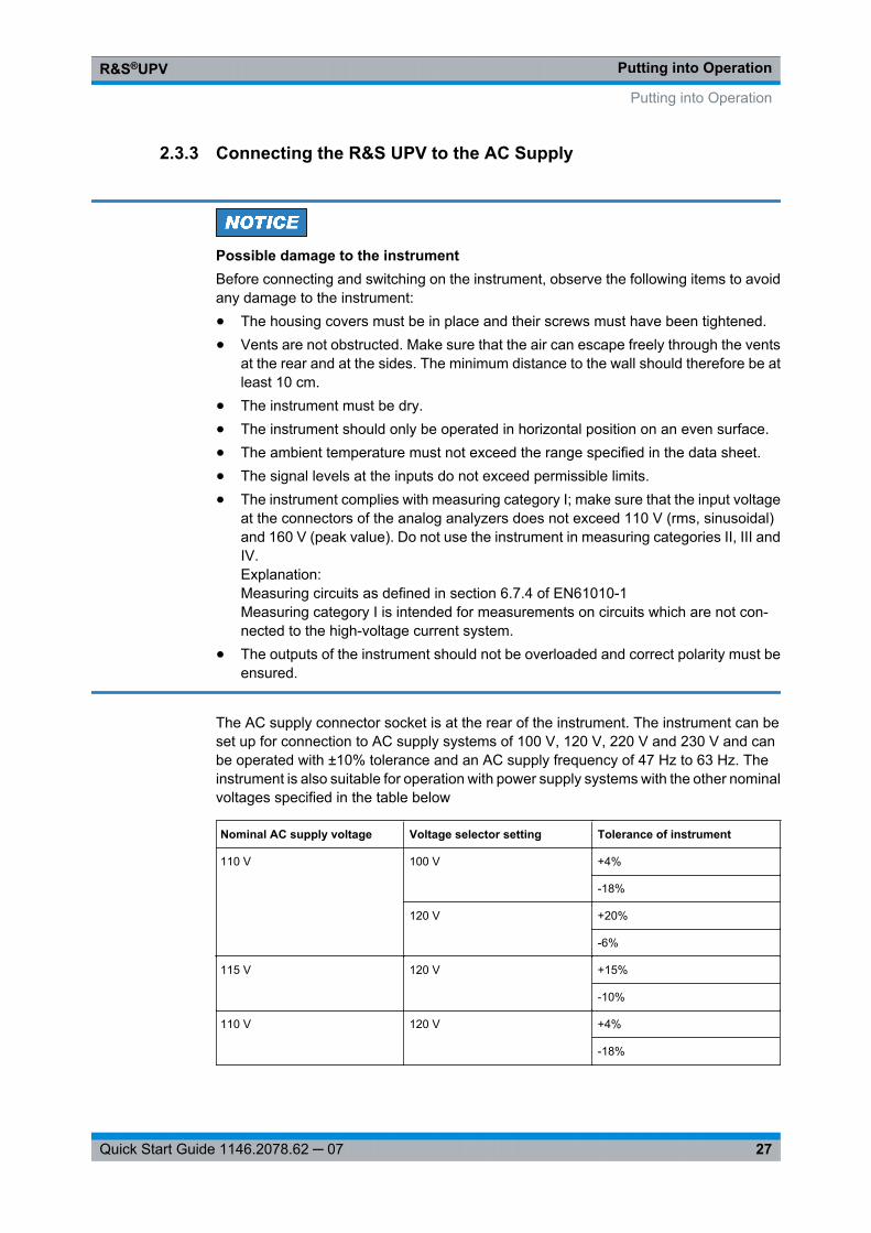
Putting into OperationR&S®UPV
27Quick Start Guide 1146.2078.62 ─ 07
2.3.3 Connecting the R&S UPV to the AC Supply
Possible damage to the instrumentBefore connecting and switching on the instrument, observe the following items to avoidany damage to the instrument:● The housing covers must be in place and their screws must have been tightened.● Vents are not obstructed. Make sure that the air can escape freely through the vents
at the rear and at the sides. The minimum distance to the wall should therefore be atleast 10 cm.
● The instrument must be dry.● The instrument should only be operated in horizontal position on an even surface.● The ambient temperature must not exceed the range specified in the data sheet.● The signal levels at the inputs do not exceed permissible limits.● The instrument complies with measuring category I; make sure that the input voltage
at the connectors of the analog analyzers does not exceed 110 V (rms, sinusoidal)and 160 V (peak value). Do not use the instrument in measuring categories II, III andIV.Explanation:Measuring circuits as defined in section 6.7.4 of EN61010-1Measuring category I is intended for measurements on circuits which are not con-nected to the high-voltage current system.
● The outputs of the instrument should not be overloaded and correct polarity must beensured.
The AC supply connector socket is at the rear of the instrument. The instrument can beset up for connection to AC supply systems of 100 V, 120 V, 220 V and 230 V and canbe operated with ±10% tolerance and an AC supply frequency of 47 Hz to 63 Hz. Theinstrument is also suitable for operation with power supply systems with the other nominalvoltages specified in the table below
Nominal AC supply voltage Voltage selector setting Tolerance of instrument
110 V 100 V +4%
-18%
120 V +20%
-6%
115 V 120 V +15%
-10%
110 V 120 V +4%
-18%
Putting into Operation
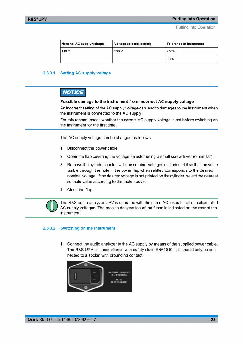
Putting into OperationR&S®UPV
28Quick Start Guide 1146.2078.62 ─ 07
Nominal AC supply voltage Voltage selector setting Tolerance of instrument
110 V 230 V +10%
-14%
2.3.3.1 Setting AC supply voltage
Possible damage to the instrument from incorrect AC supply voltageAn incorrect setting of the AC supply voltage can lead to damages to the instrument whenthe instrument is connected to the AC supply.For this reason, check whether the correct AC supply voltage is set before switching onthe instrument for the first time.
The AC supply voltage can be changed as follows:
1. Disconnect the power cable.
2. Open the flap covering the voltage selector using a small screwdriver (or similar).
3. Remove the cylinder labeled with the nominal voltages and reinsert it so that the valuevisible through the hole in the cover flap when refitted corresponds to the desirednominal voltage. If the desired voltage is not printed on the cylinder, select the nearestsuitable value according to the table above.
4. Close the flap.
The R&S audio analyzer UPV is operated with the same AC fuses for all specified ratedAC supply voltages. The precise designation of the fuses is indicated on the rear of theinstrument.
2.3.3.2 Switching on the instrument
1. Connect the audio analyzer to the AC supply by means of the supplied power cable.The R&S UPV is in compliance with safety class EN61010-1, it should only be con-nected to a socket with grounding contact.
Putting into Operation
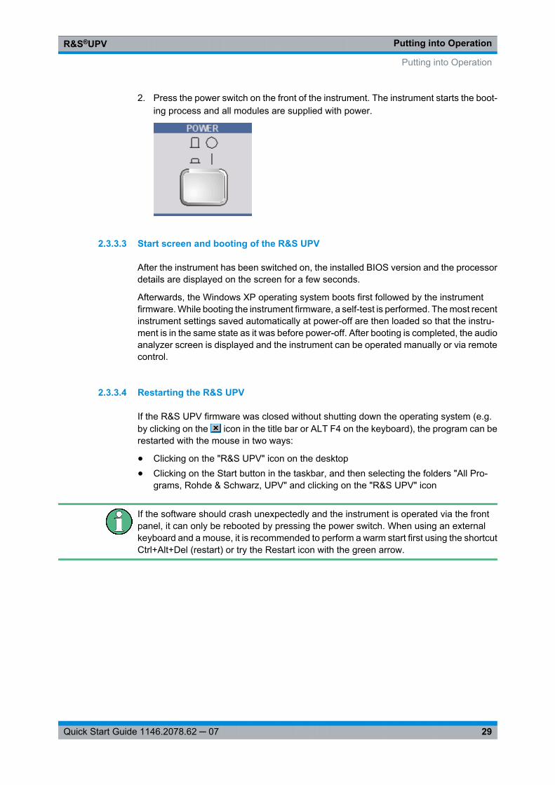
Putting into OperationR&S®UPV
29Quick Start Guide 1146.2078.62 ─ 07
2. Press the power switch on the front of the instrument. The instrument starts the boot-ing process and all modules are supplied with power.
2.3.3.3 Start screen and booting of the R&S UPV
After the instrument has been switched on, the installed BIOS version and the processordetails are displayed on the screen for a few seconds.
Afterwards, the Windows XP operating system boots first followed by the instrumentfirmware. While booting the instrument firmware, a self-test is performed. The most recentinstrument settings saved automatically at power-off are then loaded so that the instru-ment is in the same state as it was before power-off. After booting is completed, the audioanalyzer screen is displayed and the instrument can be operated manually or via remotecontrol.
2.3.3.4 Restarting the R&S UPV
If the R&S UPV firmware was closed without shutting down the operating system (e.g.by clicking on the icon in the title bar or ALT F4 on the keyboard), the program can berestarted with the mouse in two ways:
● Clicking on the "R&S UPV" icon on the desktop● Clicking on the Start button in the taskbar, and then selecting the folders "All Pro-
grams, Rohde & Schwarz, UPV" and clicking on the "R&S UPV" icon
If the software should crash unexpectedly and the instrument is operated via the frontpanel, it can only be rebooted by pressing the power switch. When using an externalkeyboard and a mouse, it is recommended to perform a warm start first using the shortcutCtrl+Alt+Del (restart) or try the Restart icon with the green arrow.
Putting into Operation
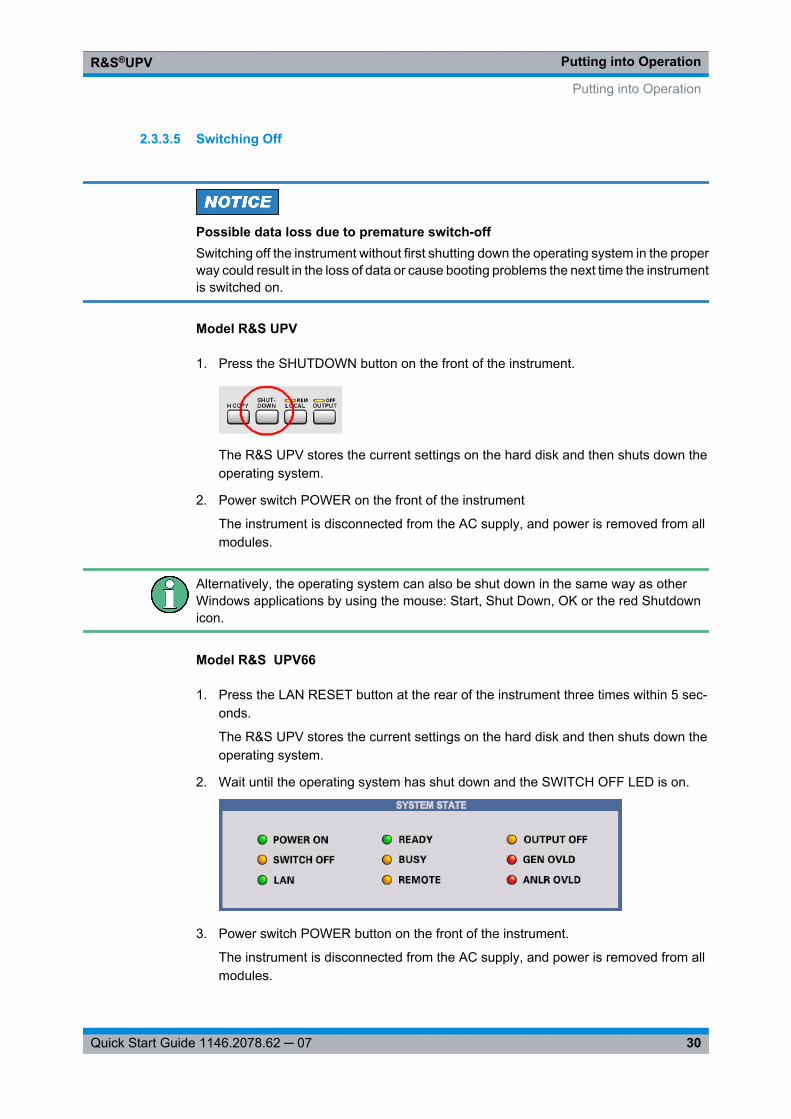
Putting into OperationR&S®UPV
30Quick Start Guide 1146.2078.62 ─ 07
2.3.3.5 Switching Off
Possible data loss due to premature switch-offSwitching off the instrument without first shutting down the operating system in the properway could result in the loss of data or cause booting problems the next time the instrumentis switched on.
Model R&S UPV
1. Press the SHUTDOWN button on the front of the instrument.
The R&S UPV stores the current settings on the hard disk and then shuts down theoperating system.
2. Power switch POWER on the front of the instrument
The instrument is disconnected from the AC supply, and power is removed from allmodules.
Alternatively, the operating system can also be shut down in the same way as otherWindows applications by using the mouse: Start, Shut Down, OK or the red Shutdownicon.
Model R&S UPV66
1. Press the LAN RESET button at the rear of the instrument three times within 5 sec-onds.
The R&S UPV stores the current settings on the hard disk and then shuts down theoperating system.
2. Wait until the operating system has shut down and the SWITCH OFF LED is on.
3. Power switch POWER button on the front of the instrument.
The instrument is disconnected from the AC supply, and power is removed from allmodules.
Putting into Operation
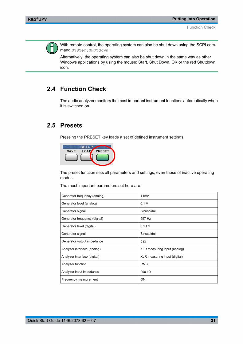
Putting into OperationR&S®UPV
31Quick Start Guide 1146.2078.62 ─ 07
With remote control, the operating system can also be shut down using the SCPI com-mand SYSTem:SHUTdown.
Alternatively, the operating system can also be shut down in the same way as otherWindows applications by using the mouse: Start, Shut Down, OK or the red Shutdownicon.
2.4 Function Check
The audio analyzer monitors the most important instrument functions automatically whenit is switched on.
2.5 Presets
Pressing the PRESET key loads a set of defined instrument settings.
The preset function sets all parameters and settings, even those of inactive operatingmodes.
The most important parameters set here are:
Generator frequency (analog) 1 kHz
Generator level (analog) 0.1 V
Generator signal Sinusoidal
Generator frequency (digital) 997 Hz
Generator level (digital) 0.1 FS
Generator signal Sinusoidal
Generator output impedance 5 Ω
Analyzer interface (analog) XLR measuring input (analog)
Analyzer interface (digital) XLR measuring input (digital)
Analyzer function RMS
Analyzer input impedance 200 kΩ
Frequency measurement ON
Function Check
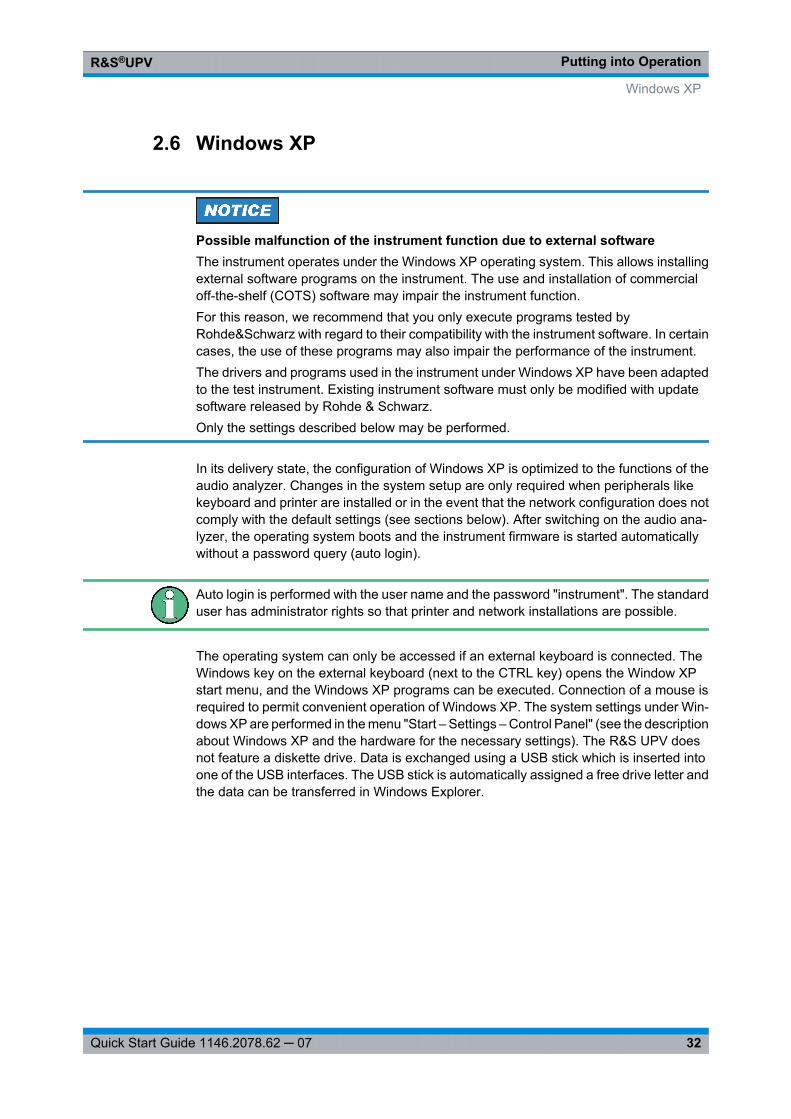
Putting into OperationR&S®UPV
32Quick Start Guide 1146.2078.62 ─ 07
2.6 Windows XP
Possible malfunction of the instrument function due to external softwareThe instrument operates under the Windows XP operating system. This allows installingexternal software programs on the instrument. The use and installation of commercialoff-the-shelf (COTS) software may impair the instrument function.For this reason, we recommend that you only execute programs tested byRohde&Schwarz with regard to their compatibility with the instrument software. In certaincases, the use of these programs may also impair the performance of the instrument.The drivers and programs used in the instrument under Windows XP have been adaptedto the test instrument. Existing instrument software must only be modified with updatesoftware released by Rohde & Schwarz.Only the settings described below may be performed.
In its delivery state, the configuration of Windows XP is optimized to the functions of theaudio analyzer. Changes in the system setup are only required when peripherals likekeyboard and printer are installed or in the event that the network configuration does notcomply with the default settings (see sections below). After switching on the audio ana-lyzer, the operating system boots and the instrument firmware is started automaticallywithout a password query (auto login).
Auto login is performed with the user name and the password "instrument". The standarduser has administrator rights so that printer and network installations are possible.
The operating system can only be accessed if an external keyboard is connected. TheWindows key on the external keyboard (next to the CTRL key) opens the Window XPstart menu, and the Windows XP programs can be executed. Connection of a mouse isrequired to permit convenient operation of Windows XP. The system settings under Win-dows XP are performed in the menu "Start – Settings – Control Panel" (see the descriptionabout Windows XP and the hardware for the necessary settings). The R&S UPV doesnot feature a diskette drive. Data is exchanged using a USB stick which is inserted intoone of the USB interfaces. The USB stick is automatically assigned a free drive letter andthe data can be transferred in Windows Explorer.
Windows XP
Putting into OperationR&S®UPV
33Quick Start Guide 1146.2078.62 ─ 07
2.7 Connecting External Keyboard and Mouse
2.7.1 Connecting an External Keyboard.
The R&S UPV allows connecting a commercially available, external keyboard with USBinterface. A keyboard simplifies the input of list entries, comment texts, file names, etc.and is required for operating Windows XP.
The keyboard is connected to one of the USB interfaces at the front or rear of the instru-ment.
The keyboard is detected automatically when it is connected. The US keyboard assign-ment is the default setting. A change of the keyboard language assignment and specialsettings, such as the repeat rate etc., can be performed in the Windows XP menu "Start- Control Panel - Keyboard" or "Regional and Language Options". The menu is openedby pressing the Windows key on the external keyboard.
2.7.2 Connecting an External Mouse
The R&S UPV allows connecting a commercially available mouse with USB interface.The mouse makes it easier to move and resize the panels / graphical windows on thescreen and provides alternative operating modes. This is recommended for convenientoperation of Windows XP.
The mouse is connected to one of the USB interfaces on the front or rear of the instrument.
The mouse is detected automatically when it is connected. Special settings, such as thespeed of the mouse cursor etc., can be performed in the Windows XP menu "Start -Control Panel - Mouse". The menu is opened by pressing the Windows key on the exter-nal keyboard.
2.8 Connecting an external monitor
Possible impairments of the instrument functionMake sure that the instrument is switched off before connecting the monitor. Otherwise,damages of the monitor and the R&S UPV cannot be ruled out.Do not modify the screen driver (Display type) and the display configuration since thiswill impair instrument operation.
The R&S UPV provides the option of connecting an external monitor via the analogMONITOR port or via the digital DVI-D socket on the rear of the instrument (only withFMR9).
Connecting External Keyboard and Mouse
Putting into OperationR&S®UPV
34Quick Start Guide 1146.2078.62 ─ 07
The interfaces of the connecting socket are described in the operating manual on the CD-ROM.
Connection
To prevent damage to the monitor and R&S UPV, the instrument must be switched offbefore an external monitor is connected. After connection, the external monitor is detec-ted when the instrument is started (but not if it is connected while the instrument is inoperation). The screen display with all elements, e.g. panels, measurement displays,softkey bar, etc., appears on the external screen. No further settings are needed.
2.8.1 Changing the screen resolution of the external monitor
The R&S UPV audio analyzer is equipped with an internal computer. Up to February2007, the instruments were supplied with a PC carrying the Rohde & Schwarz designationFMR6; instruments supplied after March 2007 included a PC of the FMR7 2012 FMR9type; instruments supplied as of March 2012 include a PC of type FMR9. The procedurefor setting the screen resolution when using an external monitor is different for the twoPC models. The procedure for each is described separately below.
Special features with the FMR9:
The Windows XP operating system used is only able to support a maximum of two mon-itors simultaneously. One of the two monitors is the internal LC display, so that only oneexternal monitor can be controlled, even if the R&S UPV with FMR9 has an analog VGAand a digital DVI port. The default setting assumes that the internal monitor and oneexternal analog VGA monitor will be used. The connected external monitor determinesthe behavior during the boot procedure depending on the selected setting under Win-dows: If an external analog VGA monitor is connected and "Notebook + Monitor" hasbeen selected under Windows, both screens will show the same content during the bootprocedure and when Windows is running. If a digital DVI monitor is connected, the internaldisplay will remain dark until Windows becomes active, independently of its Windowssetting during the boot procedure. Only after this will both displays show the same contentin parallel if "Notebook + Digital Display" was selected under Windows; Otherwise onlythe internal display becomes active under Windows.
Devices with FMR6
Set external monitor resolution to higher than 800 x 600 pixels
1. Switch off R&S UPV.
2. Connect the external monitor, keyboard and mouse.
3. Switch on R&S UPV.
4. After starting the R&S UPV, exit or minimize the UPV program by clicking on the buttons on the right in the title bar.
5. Right-click on the desktop to open the following context menu.
Connecting an external monitor

Putting into OperationR&S®UPV
35Quick Start Guide 1146.2078.62 ─ 07
6. "Select Graphics properties…".
7. Click on the "Monitor" icon.
8. Place the focus on the "True Color" field.
9. To select the hidden button (press the TAB key three times, then the spacebar, andclick on "Apply".
Connecting an external monitor
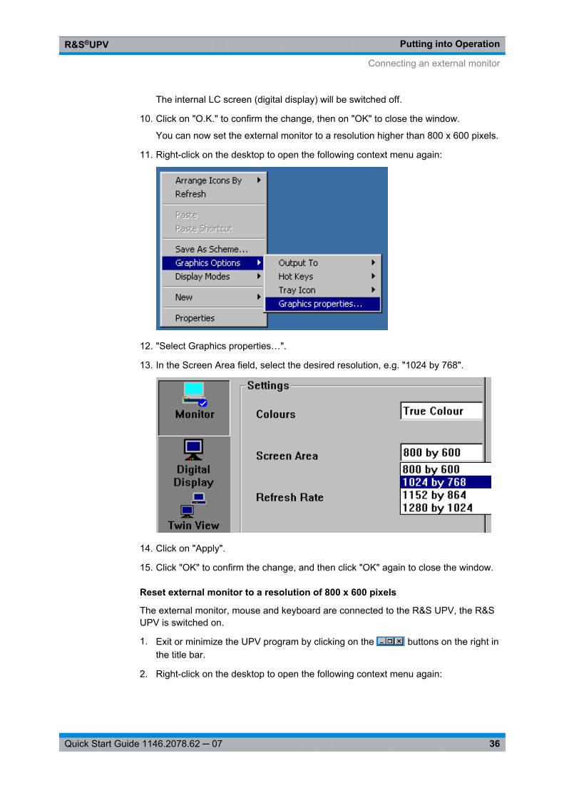
Putting into OperationR&S®UPV
36Quick Start Guide 1146.2078.62 ─ 07
The internal LC screen (digital display) will be switched off.
10. Click on "O.K." to confirm the change, then on "OK" to close the window.
You can now set the external monitor to a resolution higher than 800 x 600 pixels.
11. Right-click on the desktop to open the following context menu again:
12. "Select Graphics properties…".
13. In the Screen Area field, select the desired resolution, e.g. "1024 by 768".
14. Click on "Apply".
15. Click "OK" to confirm the change, and then click "OK" again to close the window.
Reset external monitor to a resolution of 800 x 600 pixels
The external monitor, mouse and keyboard are connected to the R&S UPV, the R&SUPV is switched on.
1. Exit or minimize the UPV program by clicking on the buttons on the right inthe title bar.
2. Right-click on the desktop to open the following context menu again:
Connecting an external monitor
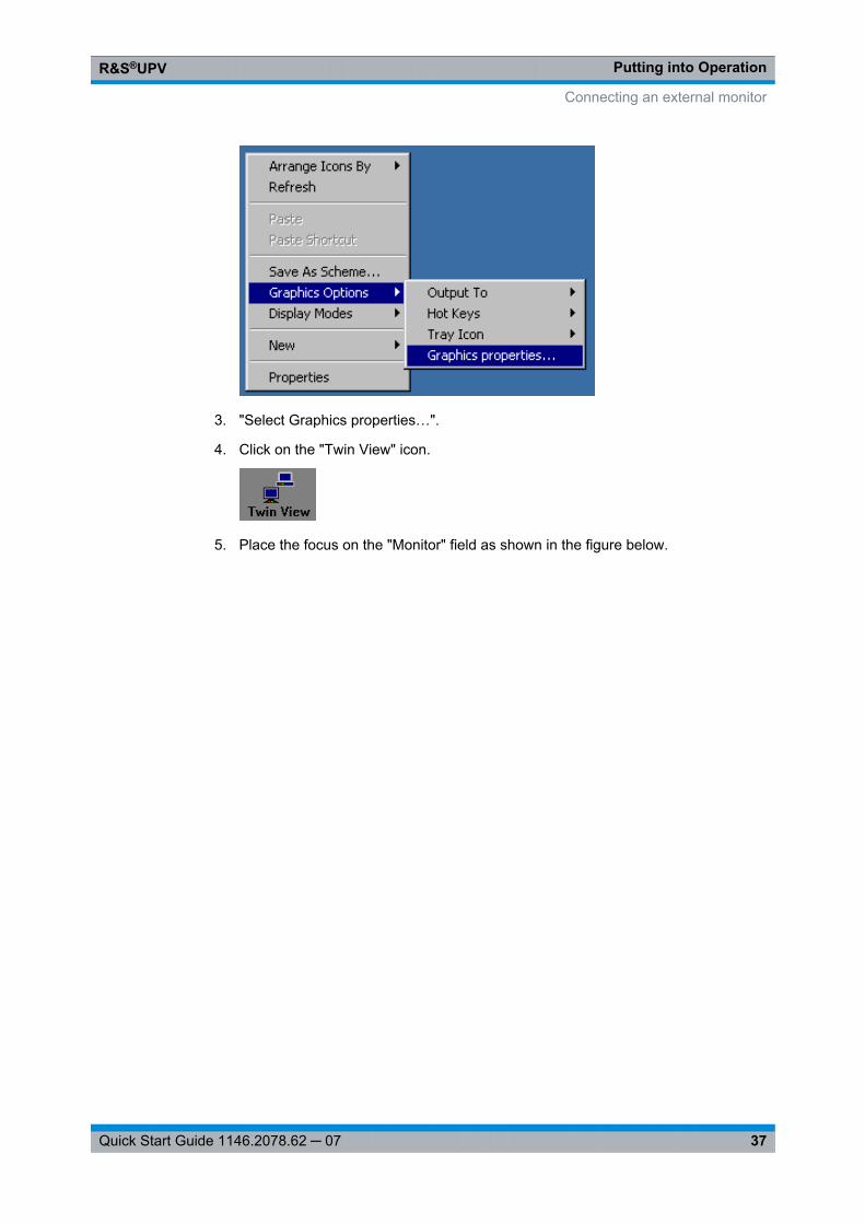
Putting into OperationR&S®UPV
37Quick Start Guide 1146.2078.62 ─ 07
3. "Select Graphics properties…".
4. Click on the "Twin View" icon.
5. Place the focus on the "Monitor" field as shown in the figure below.
Connecting an external monitor
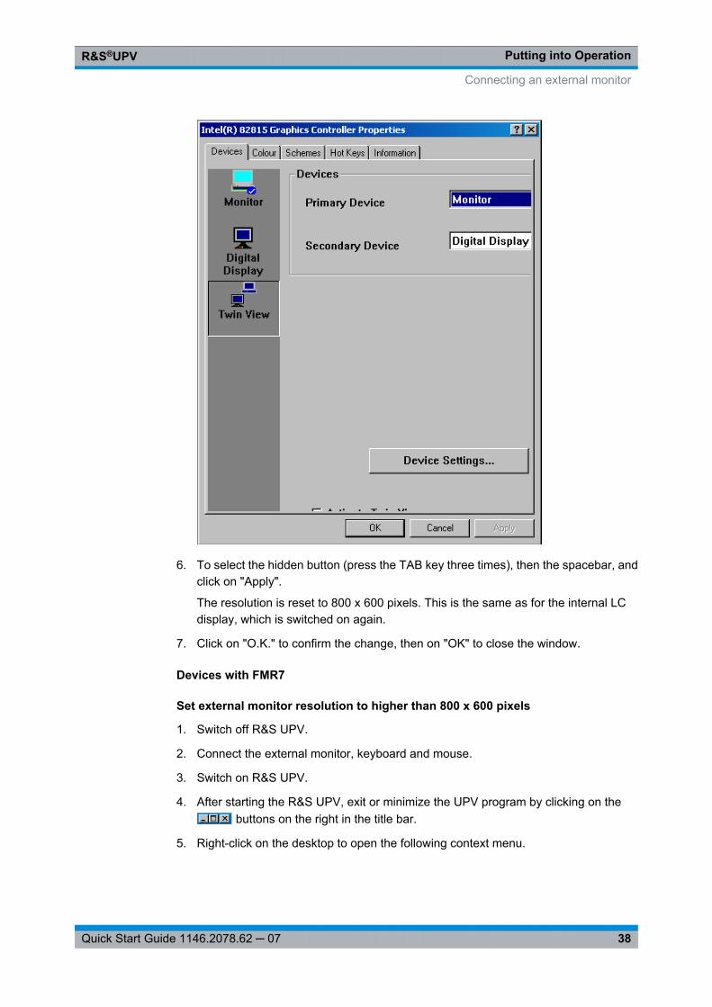
Putting into OperationR&S®UPV
38Quick Start Guide 1146.2078.62 ─ 07
6. To select the hidden button (press the TAB key three times), then the spacebar, andclick on "Apply".
The resolution is reset to 800 x 600 pixels. This is the same as for the internal LCdisplay, which is switched on again.
7. Click on "O.K." to confirm the change, then on "OK" to close the window.
Devices with FMR7
Set external monitor resolution to higher than 800 x 600 pixels
1. Switch off R&S UPV.
2. Connect the external monitor, keyboard and mouse.
3. Switch on R&S UPV.
4. After starting the R&S UPV, exit or minimize the UPV program by clicking on the buttons on the right in the title bar.
5. Right-click on the desktop to open the following context menu.
Connecting an external monitor
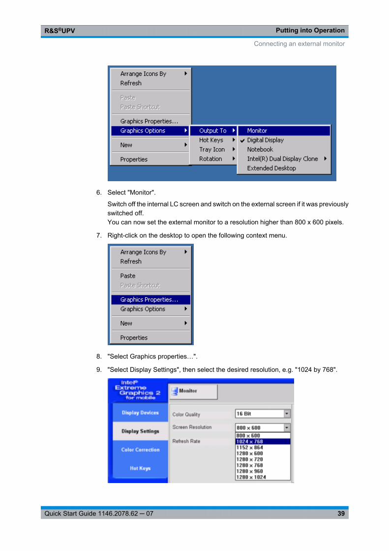
Putting into OperationR&S®UPV
39Quick Start Guide 1146.2078.62 ─ 07
6. Select "Monitor".
Switch off the internal LC screen and switch on the external screen if it was previouslyswitched off.You can now set the external monitor to a resolution higher than 800 x 600 pixels.
7. Right-click on the desktop to open the following context menu.
8. "Select Graphics properties…".
9. "Select Display Settings", then select the desired resolution, e.g. "1024 by 768".
Connecting an external monitor
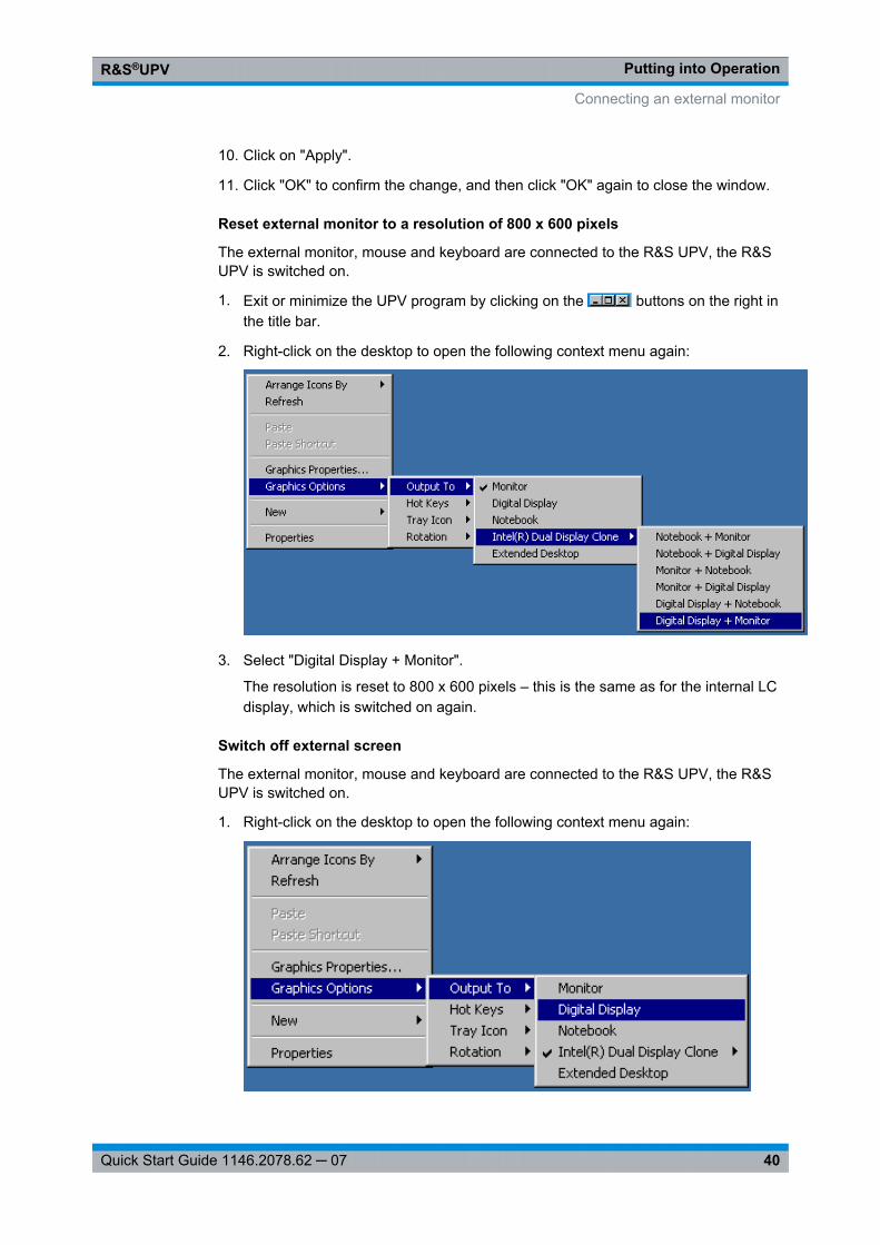
Putting into OperationR&S®UPV
40Quick Start Guide 1146.2078.62 ─ 07
10. Click on "Apply".
11. Click "OK" to confirm the change, and then click "OK" again to close the window.
Reset external monitor to a resolution of 800 x 600 pixels
The external monitor, mouse and keyboard are connected to the R&S UPV, the R&SUPV is switched on.
1. Exit or minimize the UPV program by clicking on the buttons on the right inthe title bar.
2. Right-click on the desktop to open the following context menu again:
3. Select "Digital Display + Monitor".
The resolution is reset to 800 x 600 pixels – this is the same as for the internal LCdisplay, which is switched on again.
Switch off external screen
The external monitor, mouse and keyboard are connected to the R&S UPV, the R&SUPV is switched on.
1. Right-click on the desktop to open the following context menu again:
Connecting an external monitor
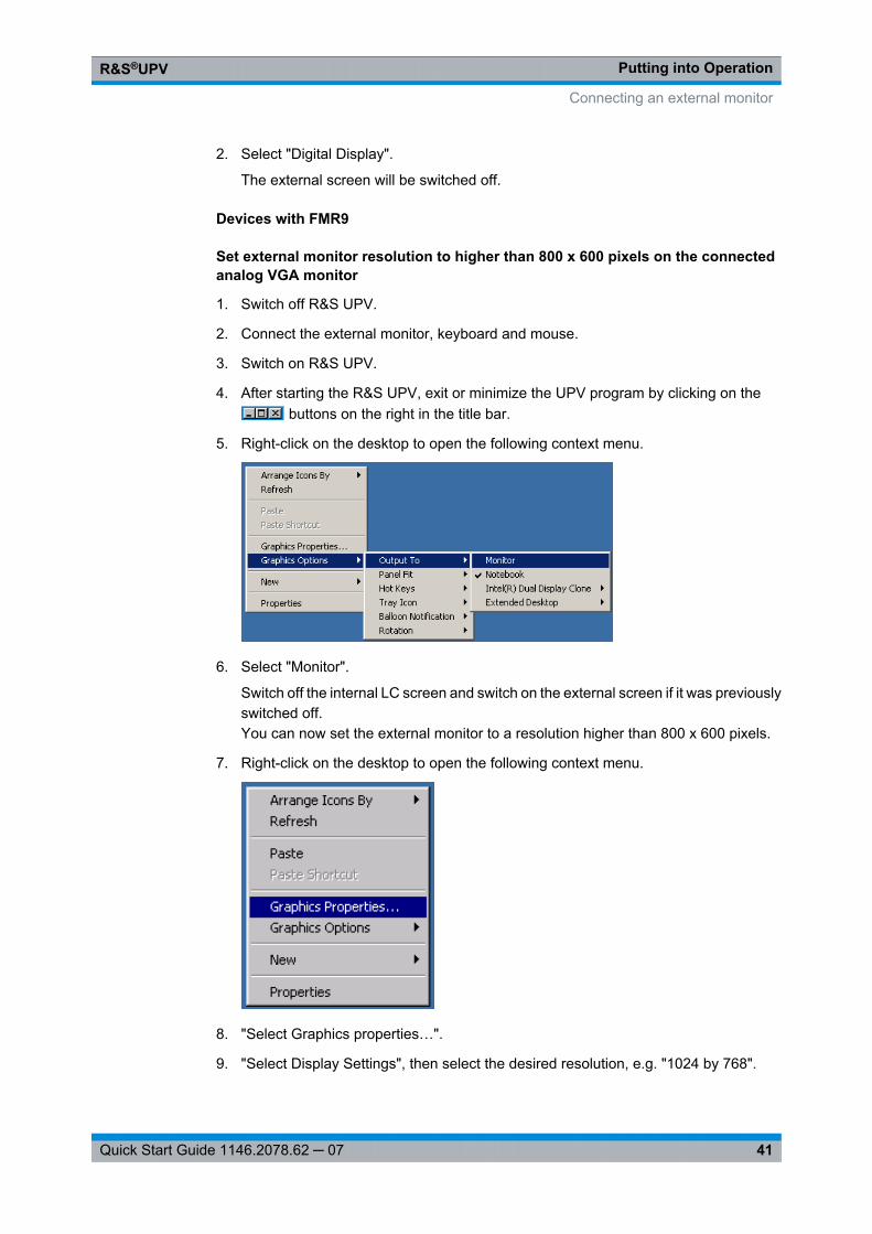
Putting into OperationR&S®UPV
41Quick Start Guide 1146.2078.62 ─ 07
2. Select "Digital Display".
The external screen will be switched off.
Devices with FMR9
Set external monitor resolution to higher than 800 x 600 pixels on the connectedanalog VGA monitor
1. Switch off R&S UPV.
2. Connect the external monitor, keyboard and mouse.
3. Switch on R&S UPV.
4. After starting the R&S UPV, exit or minimize the UPV program by clicking on the buttons on the right in the title bar.
5. Right-click on the desktop to open the following context menu.
6. Select "Monitor".
Switch off the internal LC screen and switch on the external screen if it was previouslyswitched off.You can now set the external monitor to a resolution higher than 800 x 600 pixels.
7. Right-click on the desktop to open the following context menu.
8. "Select Graphics properties…".
9. "Select Display Settings", then select the desired resolution, e.g. "1024 by 768".
Connecting an external monitor
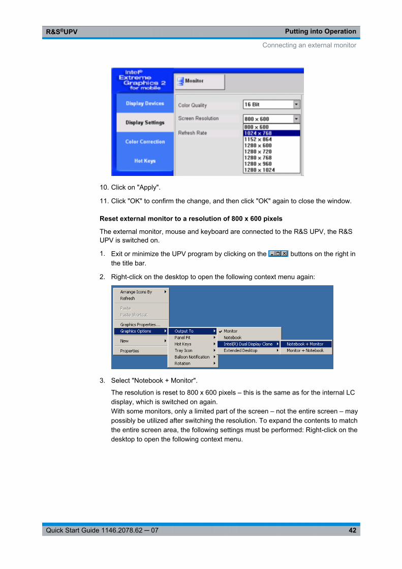
Putting into OperationR&S®UPV
42Quick Start Guide 1146.2078.62 ─ 07
10. Click on "Apply".
11. Click "OK" to confirm the change, and then click "OK" again to close the window.
Reset external monitor to a resolution of 800 x 600 pixels
The external monitor, mouse and keyboard are connected to the R&S UPV, the R&SUPV is switched on.
1. Exit or minimize the UPV program by clicking on the buttons on the right inthe title bar.
2. Right-click on the desktop to open the following context menu again:
3. Select "Notebook + Monitor".
The resolution is reset to 800 x 600 pixels – this is the same as for the internal LCdisplay, which is switched on again.With some monitors, only a limited part of the screen – not the entire screen – maypossibly be utilized after switching the resolution. To expand the contents to matchthe entire screen area, the following settings must be performed: Right-click on thedesktop to open the following context menu.
Connecting an external monitor
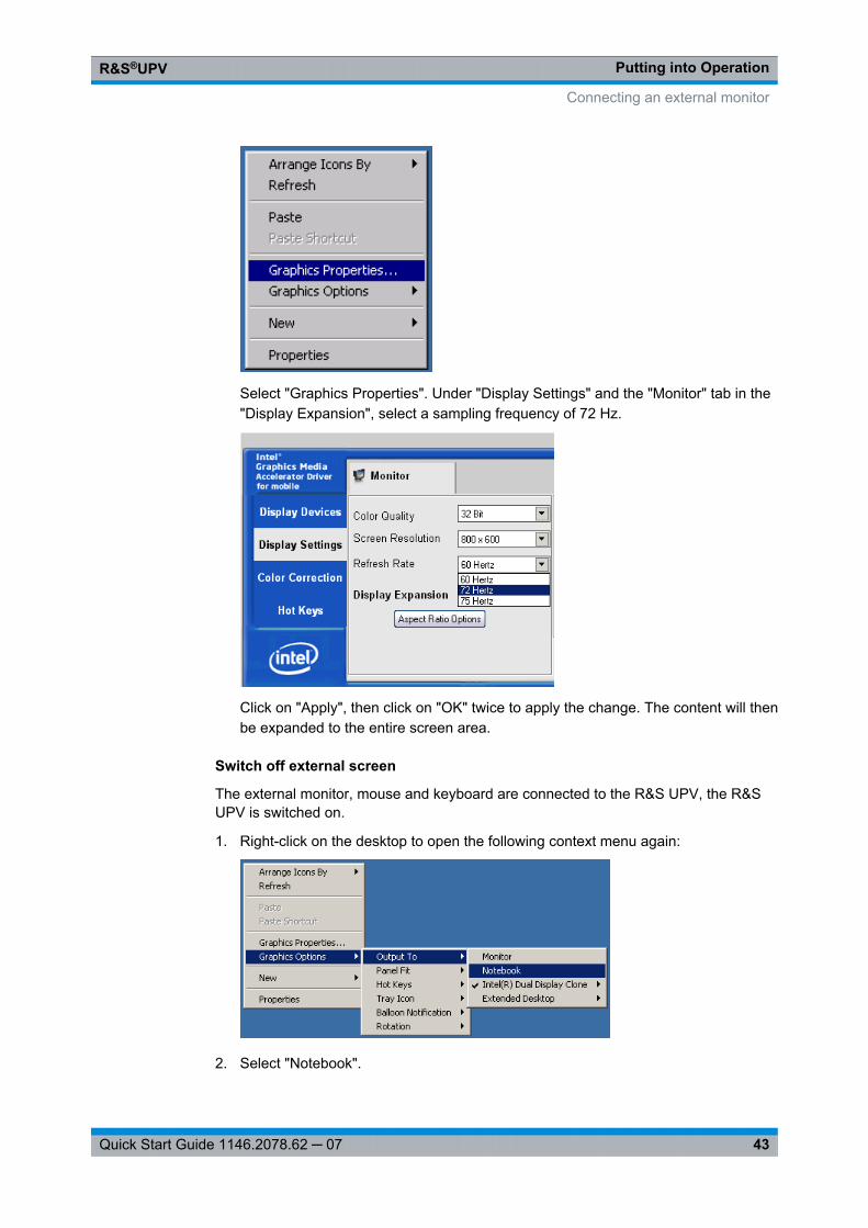
Putting into OperationR&S®UPV
43Quick Start Guide 1146.2078.62 ─ 07
Select "Graphics Properties". Under "Display Settings" and the "Monitor" tab in the"Display Expansion", select a sampling frequency of 72 Hz.
Click on "Apply", then click on "OK" twice to apply the change. The content will thenbe expanded to the entire screen area.
Switch off external screen
The external monitor, mouse and keyboard are connected to the R&S UPV, the R&SUPV is switched on.
1. Right-click on the desktop to open the following context menu again:
2. Select "Notebook".
Connecting an external monitor
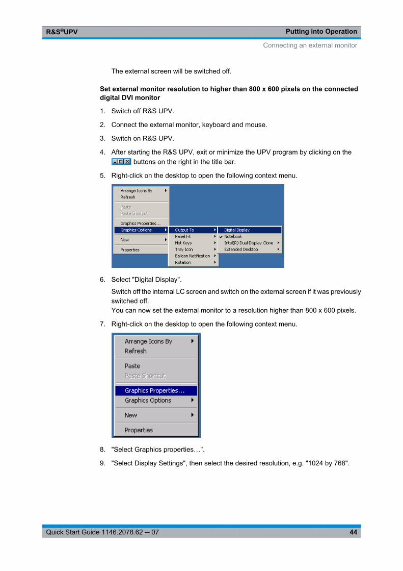
Putting into OperationR&S®UPV
44Quick Start Guide 1146.2078.62 ─ 07
The external screen will be switched off.
Set external monitor resolution to higher than 800 x 600 pixels on the connecteddigital DVI monitor
1. Switch off R&S UPV.
2. Connect the external monitor, keyboard and mouse.
3. Switch on R&S UPV.
4. After starting the R&S UPV, exit or minimize the UPV program by clicking on the buttons on the right in the title bar.
5. Right-click on the desktop to open the following context menu.
6. Select "Digital Display".
Switch off the internal LC screen and switch on the external screen if it was previouslyswitched off.You can now set the external monitor to a resolution higher than 800 x 600 pixels.
7. Right-click on the desktop to open the following context menu.
8. "Select Graphics properties…".
9. "Select Display Settings", then select the desired resolution, e.g. "1024 by 768".
Connecting an external monitor
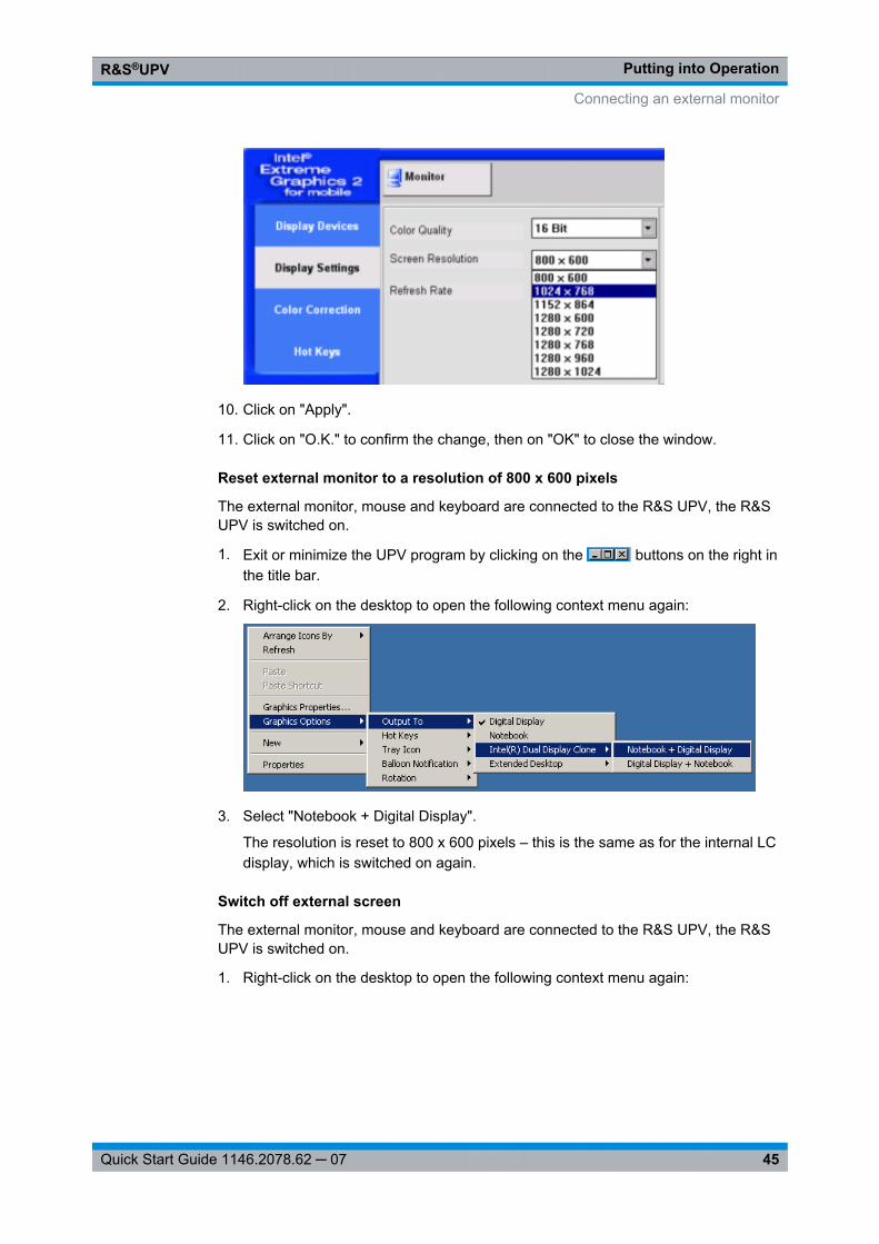
Putting into OperationR&S®UPV
45Quick Start Guide 1146.2078.62 ─ 07
10. Click on "Apply".
11. Click on "O.K." to confirm the change, then on "OK" to close the window.
Reset external monitor to a resolution of 800 x 600 pixels
The external monitor, mouse and keyboard are connected to the R&S UPV, the R&SUPV is switched on.
1. Exit or minimize the UPV program by clicking on the buttons on the right inthe title bar.
2. Right-click on the desktop to open the following context menu again:
3. Select "Notebook + Digital Display".
The resolution is reset to 800 x 600 pixels – this is the same as for the internal LCdisplay, which is switched on again.
Switch off external screen
The external monitor, mouse and keyboard are connected to the R&S UPV, the R&SUPV is switched on.
1. Right-click on the desktop to open the following context menu again:
Connecting an external monitor
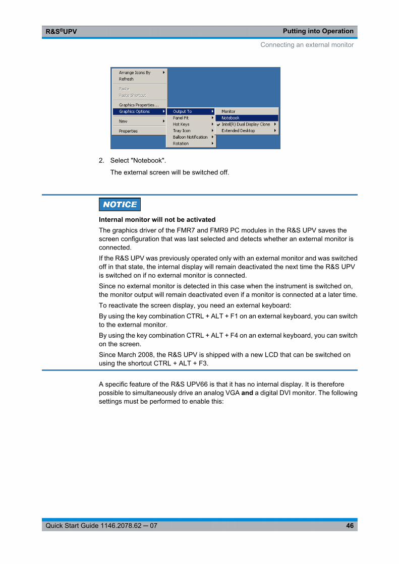
Putting into OperationR&S®UPV
46Quick Start Guide 1146.2078.62 ─ 07
2. Select "Notebook".
The external screen will be switched off.
Internal monitor will not be activatedThe graphics driver of the FMR7 and FMR9 PC modules in the R&S UPV saves thescreen configuration that was last selected and detects whether an external monitor isconnected.If the R&S UPV was previously operated only with an external monitor and was switchedoff in that state, the internal display will remain deactivated the next time the R&S UPVis switched on if no external monitor is connected.Since no external monitor is detected in this case when the instrument is switched on,the monitor output will remain deactivated even if a monitor is connected at a later time.To reactivate the screen display, you need an external keyboard:By using the key combination CTRL + ALT + F1 on an external keyboard, you can switchto the external monitor.By using the key combination CTRL + ALT + F4 on an external keyboard, you can switchon the screen.Since March 2008, the R&S UPV is shipped with a new LCD that can be switched onusing the shortcut CTRL + ALT + F3.
A specific feature of the R&S UPV66 is that it has no internal display. It is thereforepossible to simultaneously drive an analog VGA and a digital DVI monitor. The followingsettings must be performed to enable this:
Connecting an external monitor
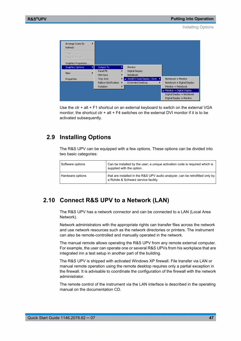
Putting into OperationR&S®UPV
47Quick Start Guide 1146.2078.62 ─ 07
Use the ctr + alt + F1 shortcut on an external keyboard to switch on the external VGAmonitor; the shortcut ctr + alt + F4 switches on the external DVI monitor if it is to beactivated subsequently.
2.9 Installing Options
The R&S UPV can be equipped with a few options. These options can be divided intotwo basic categories:
Software options Can be installed by the user; a unique activation code is required which issupplied with the option.
Hardware options that are installed in the R&S UPV audio analyzer, can be retrofitted only bya Rohde & Schwarz service facility.
2.10 Connect R&S UPV to a Network (LAN)
The R&S UPV has a network connector and can be connected to a LAN (Local AreaNetwork).
Network administrators with the appropriate rights can transfer files across the networkand use network resources such as the network directories or printers. The instrumentcan also be remote-controlled and manually operated in the network.
The manual remote allows operating the R&S UPV from any remote external computer.For example, the user can operate one or several R&S UPVs from his workplace that areintegrated inn a test setup in another part of the building.
The R&S UPV is shipped with activated Windows XP firewall. File transfer via LAN ormanual remote operation using the remote desktop requires only a partial exception inthe firewall. It is advisable to coordinate the configuration of the firewall with the networkadministrator.
The remote control of the instrument via the LAN interface is described in the operatingmanual on the documentation CD.
Installing Options
Putting into OperationR&S®UPV
48Quick Start Guide 1146.2078.62 ─ 07
2.10.1 Connection to the Network
Possible malfunction of the network operationIt is recommended that the connection of the instrument to the network be coordinatedwith the network administrator. Connection errors may affect the entire network.Do not connect or disconnect the network cable until the instrument is switched off(standby). Only then can the network connection be reliably detected and impairmentsto instrument operation can be avoided.
The instrument is connected to the network using a commercially available RJ-45 cableconnected to the LAN interface at the rear of the instrument.
2.10.2 Configuration of R&S UPV for Network Operation
The network interface operates with 100-MHz Ethernet IEEE 802.3u. The TCP/IP net-work protocol and the associated network services are preconfigured.
In order to exchange data in a local network (LAN), each connected computer or instru-ment must have a unique IP address or a unique computer name. In addition, networkaccess of the different users is organized by the assignment of access rights.
The access rights determine which of the available network resources, e.g. file storagesystems, are available for the R&S UPV.
Networks with DHCP
The R&S UPV is preconfigured for networks using DHCP (dynamic host configurationprotocol). In these networks, the R&S UPV is automatically assigned an unused IPaddress.
In this case, a unique computer name is used for identification in the network. Every R&SUPV is assigned an individual computer name at the factory. This name can be queriedin the Windows XP menu "Start - My Computer" and changed (see chapter 2.10.2.3,"Querying the computer name", on page 52).
Networks with fixed IP addresses
In networks using fixed IP addresses, the addresses are mostly assigned by the networkadministrator. The fixed IP address must be entered in the Windows XP menu "Start -Control Panel" (see chapter 2.10.2.2, "Entering the IP Address", on page 49).
Connect R&S UPV to a Network (LAN)
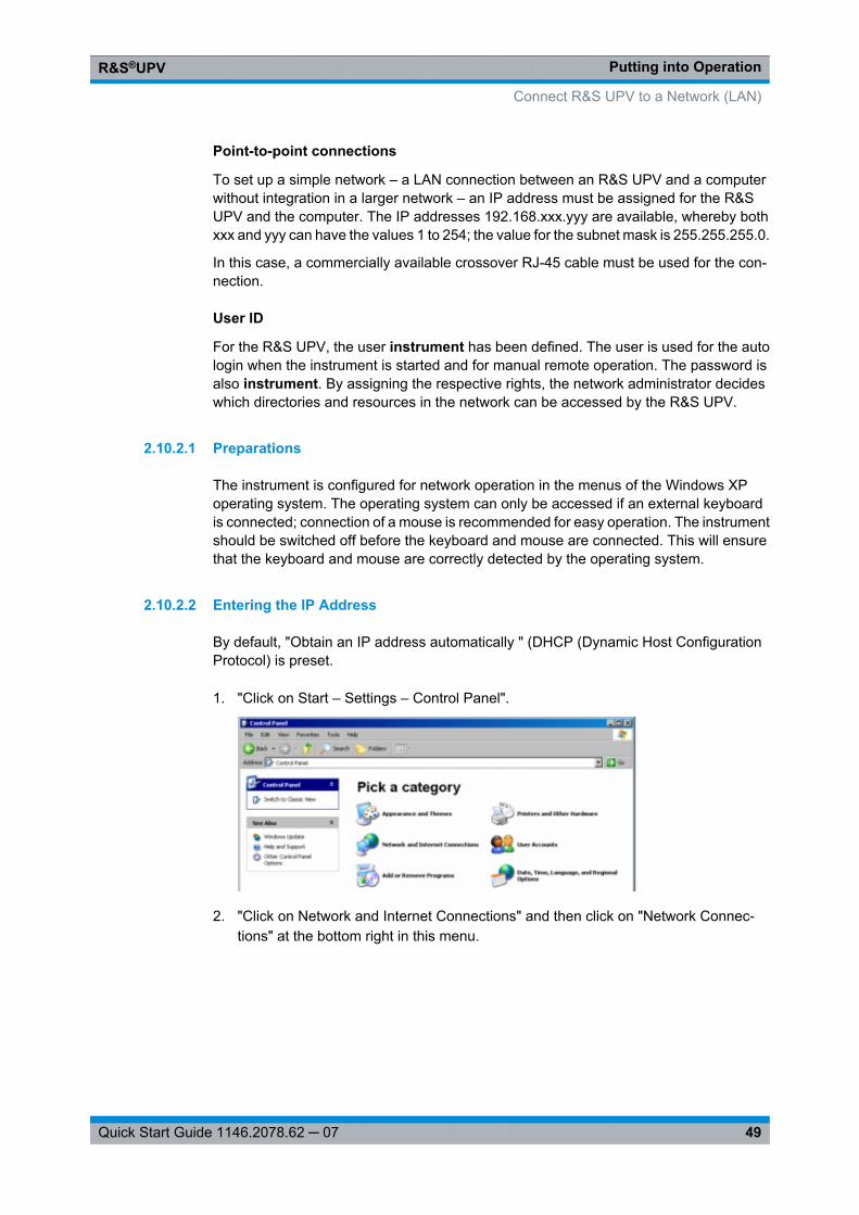
Putting into OperationR&S®UPV
49Quick Start Guide 1146.2078.62 ─ 07
Point-to-point connections
To set up a simple network – a LAN connection between an R&S UPV and a computerwithout integration in a larger network – an IP address must be assigned for the R&SUPV and the computer. The IP addresses 192.168.xxx.yyy are available, whereby bothxxx and yyy can have the values 1 to 254; the value for the subnet mask is 255.255.255.0.
In this case, a commercially available crossover RJ-45 cable must be used for the con-nection.
User ID
For the R&S UPV, the user instrument has been defined. The user is used for the autologin when the instrument is started and for manual remote operation. The password isalso instrument. By assigning the respective rights, the network administrator decideswhich directories and resources in the network can be accessed by the R&S UPV.
2.10.2.1 Preparations
The instrument is configured for network operation in the menus of the Windows XPoperating system. The operating system can only be accessed if an external keyboardis connected; connection of a mouse is recommended for easy operation. The instrumentshould be switched off before the keyboard and mouse are connected. This will ensurethat the keyboard and mouse are correctly detected by the operating system.
2.10.2.2 Entering the IP Address
By default, "Obtain an IP address automatically " (DHCP (Dynamic Host ConfigurationProtocol) is preset.
1. "Click on Start – Settings – Control Panel".
2. "Click on Network and Internet Connections" and then click on "Network Connec-tions" at the bottom right in this menu.
Connect R&S UPV to a Network (LAN)
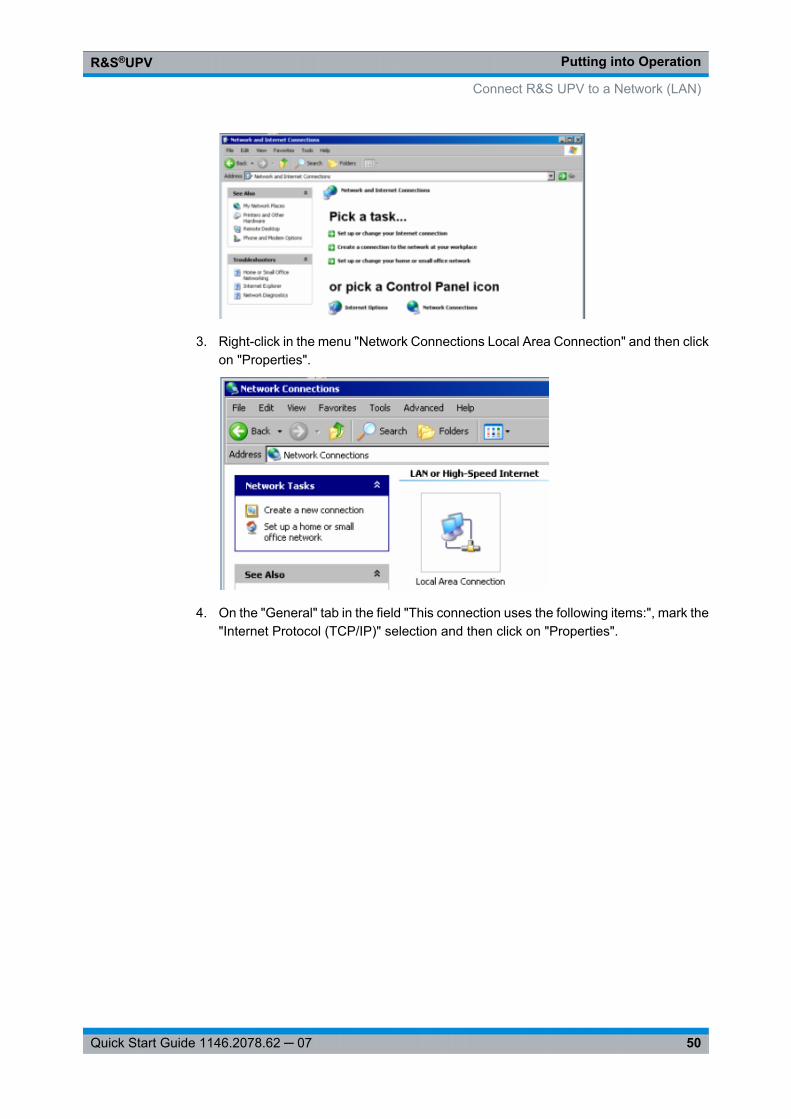
Putting into OperationR&S®UPV
50Quick Start Guide 1146.2078.62 ─ 07
3. Right-click in the menu "Network Connections Local Area Connection" and then clickon "Properties".
4. On the "General" tab in the field "This connection uses the following items:", mark the"Internet Protocol (TCP/IP)" selection and then click on "Properties".
Connect R&S UPV to a Network (LAN)
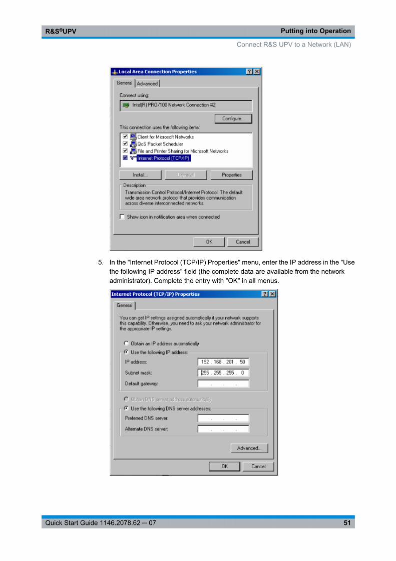
Putting into OperationR&S®UPV
51Quick Start Guide 1146.2078.62 ─ 07
5. In the "Internet Protocol (TCP/IP) Properties" menu, enter the IP address in the "Usethe following IP address" field (the complete data are available from the networkadministrator). Complete the entry with "OK" in all menus.
Connect R&S UPV to a Network (LAN)
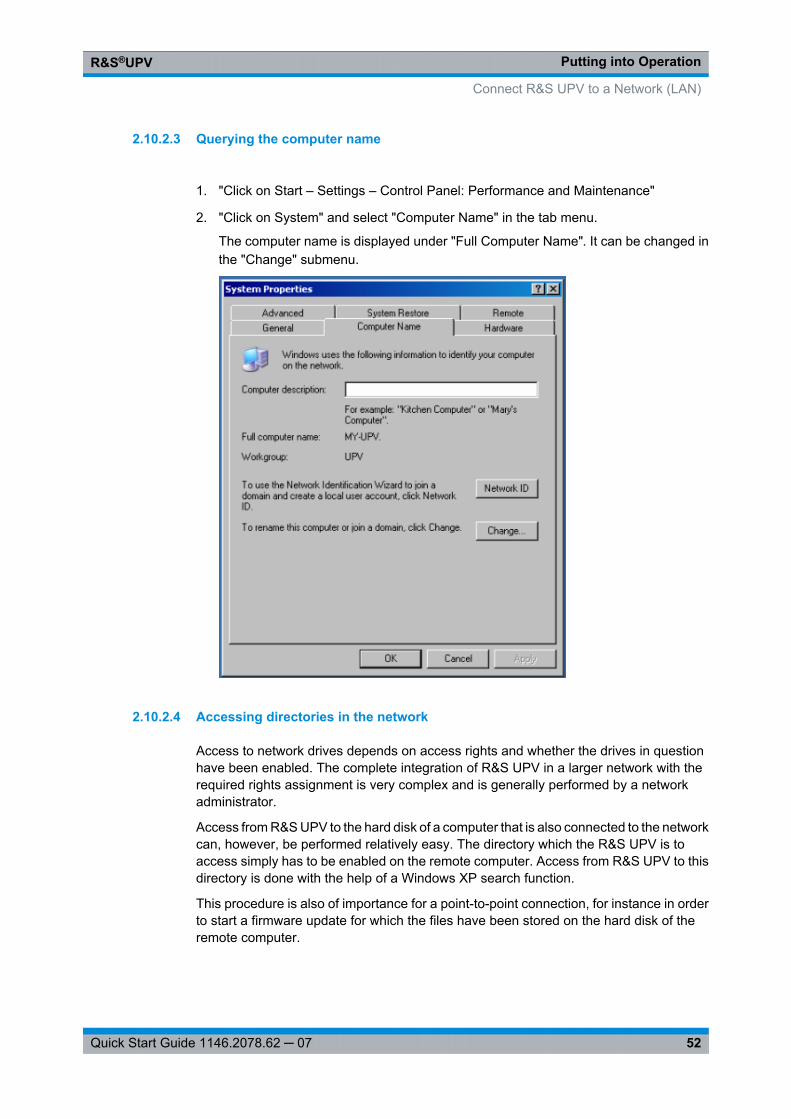
Putting into OperationR&S®UPV
52Quick Start Guide 1146.2078.62 ─ 07
2.10.2.3 Querying the computer name
1. "Click on Start – Settings – Control Panel: Performance and Maintenance"
2. "Click on System" and select "Computer Name" in the tab menu.
The computer name is displayed under "Full Computer Name". It can be changed inthe "Change" submenu.
2.10.2.4 Accessing directories in the network
Access to network drives depends on access rights and whether the drives in questionhave been enabled. The complete integration of R&S UPV in a larger network with therequired rights assignment is very complex and is generally performed by a networkadministrator.
Access from R&S UPV to the hard disk of a computer that is also connected to the networkcan, however, be performed relatively easy. The directory which the R&S UPV is toaccess simply has to be enabled on the remote computer. Access from R&S UPV to thisdirectory is done with the help of a Windows XP search function.
This procedure is also of importance for a point-to-point connection, for instance in orderto start a firmware update for which the files have been stored on the hard disk of theremote computer.
Connect R&S UPV to a Network (LAN)
Putting into OperationR&S®UPV
53Quick Start Guide 1146.2078.62 ─ 07
Both the computer and the audio analyzer must have a computer name and an IP address(see chapter 2.10.2, "Configuration of R&S UPV for Network Operation", on page 48).The menu name may deviate from the name specified in the following operatingsequence, depending on the language and on the operating system used on the com-puter.
Enabling the desired directory on the remote computer
1. On the computer, select the directory to be enabled in Windows Explorer and right-click to call up the "Properties" menu.
2. In the "Sharing" panel, activate the "Share this folder" check box.
3. Record the computer name of the PC (see chapter 2.10.2.3, "Querying the computername", on page 52).
At the R&S UPV, access the enabled directory
1. Use the Windows key to call up the "Start" menu.
2. In the menu, select "Search Computers or People", followed by "A Computer on theNetwork".
3. In the input window with the query "Which computer are you looking for?", enter thename of the computer and start the search with Enter.
The PC is listed with its computer name as the search result.
4. Click on the computer name. The enabled directory is displayed and the files storedin it can be used in the R&S UPV.
Note: If a user name and password are requested when you click the computer, thelogin name and password used on the computer must be entered.
2.10.3 Configuration via LXI
Be default, LXI is only available to the R&S UPV66, but it can also be installed on theR&S UPV at a later time, if needed.The LXI functionality for the R&S UPV66 requires the Windows XP operating system withService Pack 2 which may not yet be installed on older computers. If this is the case,please contact your Rohde & Schwarz subsidiary. The version of the operating systemcan be checked under "Instrument Properties" in the "General" menu.
LAN eXtensions for Instrumentation (LXI) is an instrumentation platform for measuringinstruments and test systems that is based on standard Ethernet technology. LXI isintended to be the LAN-based successor to GPIB, combining the advantages of Ethernetwith the simplicity and familiarity of GPIB. This standard provides a new way for config-uring virtual front panel instruments by using a network and a Web interface. The main
Connect R&S UPV to a Network (LAN)
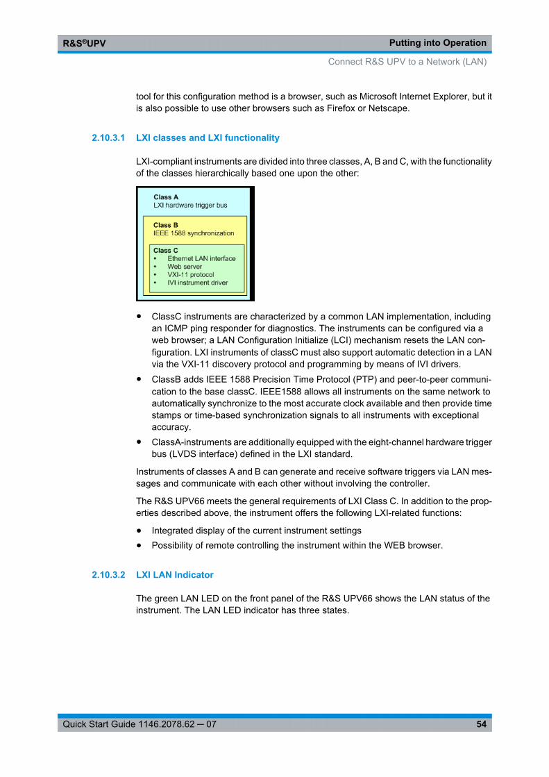
Putting into OperationR&S®UPV
54Quick Start Guide 1146.2078.62 ─ 07
tool for this configuration method is a browser, such as Microsoft Internet Explorer, but itis also possible to use other browsers such as Firefox or Netscape.
2.10.3.1 LXI classes and LXI functionality
LXI-compliant instruments are divided into three classes, A, B and C, with the functionalityof the classes hierarchically based one upon the other:
● ClassC instruments are characterized by a common LAN implementation, includingan ICMP ping responder for diagnostics. The instruments can be configured via aweb browser; a LAN Configuration Initialize (LCI) mechanism resets the LAN con-figuration. LXI instruments of classC must also support automatic detection in a LANvia the VXI-11 discovery protocol and programming by means of IVI drivers.
● ClassB adds IEEE 1588 Precision Time Protocol (PTP) and peer-to-peer communi-cation to the base classC. IEEE1588 allows all instruments on the same network toautomatically synchronize to the most accurate clock available and then provide timestamps or time-based synchronization signals to all instruments with exceptionalaccuracy.
● ClassA-instruments are additionally equipped with the eight-channel hardware triggerbus (LVDS interface) defined in the LXI standard.
Instruments of classes A and B can generate and receive software triggers via LAN mes-sages and communicate with each other without involving the controller.
The R&S UPV66 meets the general requirements of LXI Class C. In addition to the prop-erties described above, the instrument offers the following LXI-related functions:
● Integrated display of the current instrument settings● Possibility of remote controlling the instrument within the WEB browser.
2.10.3.2 LXI LAN Indicator
The green LAN LED on the front panel of the R&S UPV66 shows the LAN status of theinstrument. The LAN LED indicator has three states.
Connect R&S UPV to a Network (LAN)
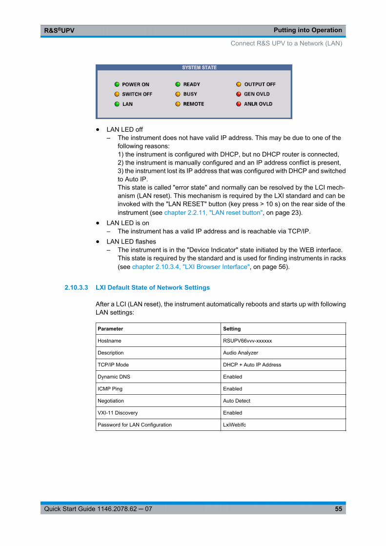
Putting into OperationR&S®UPV
55Quick Start Guide 1146.2078.62 ─ 07
● LAN LED off– The instrument does not have valid IP address. This may be due to one of the
following reasons:1) the instrument is configured with DHCP, but no DHCP router is connected,2) the instrument is manually configured and an IP address conflict is present,3) the instrument lost its IP address that was configured with DHCP and switchedto Auto IP.This state is called "error state" and normally can be resolved by the LCI mech-anism (LAN reset). This mechanism is required by the LXI standard and can beinvoked with the "LAN RESET" button (key press > 10 s) on the rear side of theinstrument (see chapter 2.2.11, "LAN reset button", on page 23).
● LAN LED is on– The instrument has a valid IP address and is reachable via TCP/IP.
● LAN LED flashes– The instrument is in the "Device Indicator" state initiated by the WEB interface.
This state is required by the standard and is used for finding instruments in racks(see chapter 2.10.3.4, "LXI Browser Interface", on page 56).
2.10.3.3 LXI Default State of Network Settings
After a LCI (LAN reset), the instrument automatically reboots and starts up with followingLAN settings:
Parameter Setting
Hostname RSUPV66vvv-xxxxxx
Description Audio Analyzer
TCP/IP Mode DHCP + Auto IP Address
Dynamic DNS Enabled
ICMP Ping Enabled
Negotiation Auto Detect
VXI-11 Discovery Enabled
Password for LAN Configuration LxiWebIfc
Connect R&S UPV to a Network (LAN)
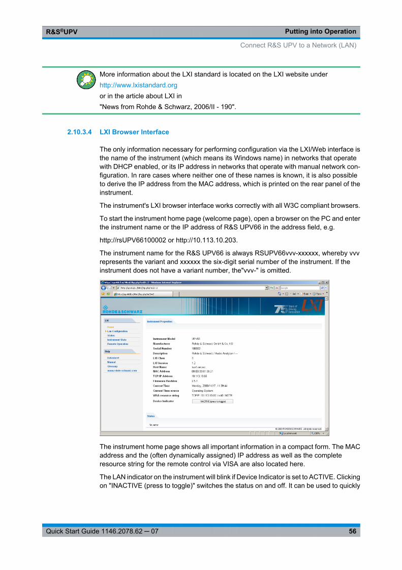
Putting into OperationR&S®UPV
56Quick Start Guide 1146.2078.62 ─ 07
More information about the LXI standard is located on the LXI website underhttp://www.lxistandard.orgor in the article about LXI in"News from Rohde & Schwarz, 2006/II - 190".
2.10.3.4 LXI Browser Interface
The only information necessary for performing configuration via the LXI/Web interface isthe name of the instrument (which means its Windows name) in networks that operatewith DHCP enabled, or its IP address in networks that operate with manual network con-figuration. In rare cases where neither one of these names is known, it is also possibleto derive the IP address from the MAC address, which is printed on the rear panel of theinstrument.
The instrument's LXI browser interface works correctly with all W3C compliant browsers.
To start the instrument home page (welcome page), open a browser on the PC and enterthe instrument name or the IP address of R&S UPV66 in the address field, e.g.
http://rsUPV66100002 or http://10.113.10.203.
The instrument name for the R&S UPV66 is always RSUPV66vvv-xxxxxx, whereby vvvrepresents the variant and xxxxxx the six-digit serial number of the instrument. If theinstrument does not have a variant number, the"vvv-" is omitted.
The instrument home page shows all important information in a compact form. The MACaddress and the (often dynamically assigned) IP address as well as the completeresource string for the remote control via VISA are also located here.
The LAN indicator on the instrument will blink if Device Indicator is set to ACTIVE. Clickingon "INACTIVE (press to toggle)" switches the status on and off. It can be used to quickly
Connect R&S UPV to a Network (LAN)
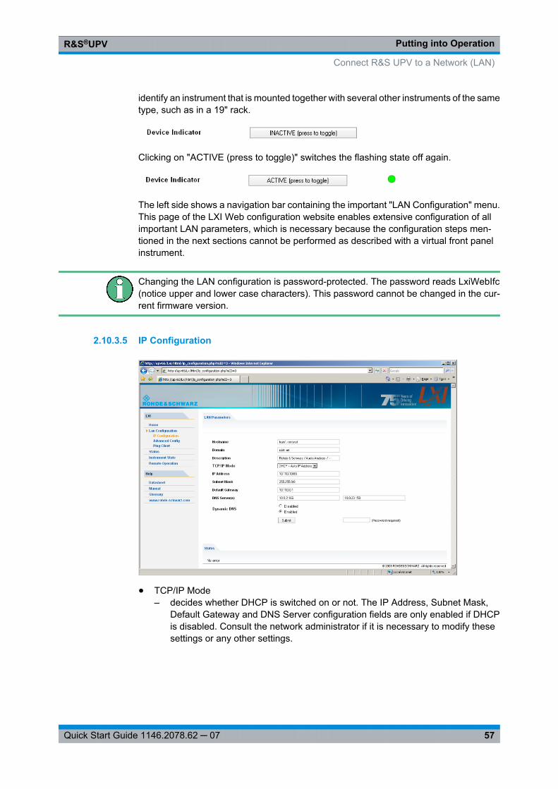
Putting into OperationR&S®UPV
57Quick Start Guide 1146.2078.62 ─ 07
identify an instrument that is mounted together with several other instruments of the sametype, such as in a 19" rack.
Clicking on "ACTIVE (press to toggle)" switches the flashing state off again.
The left side shows a navigation bar containing the important "LAN Configuration" menu.This page of the LXI Web configuration website enables extensive configuration of allimportant LAN parameters, which is necessary because the configuration steps men-tioned in the next sections cannot be performed as described with a virtual front panelinstrument.
Changing the LAN configuration is password-protected. The password reads LxiWebIfc(notice upper and lower case characters). This password cannot be changed in the cur-rent firmware version.
2.10.3.5 IP Configuration
● TCP/IP Mode– decides whether DHCP is switched on or not. The IP Address, Subnet Mask,
Default Gateway and DNS Server configuration fields are only enabled if DHCPis disabled. Consult the network administrator if it is necessary to modify thesesettings or any other settings.
Connect R&S UPV to a Network (LAN)
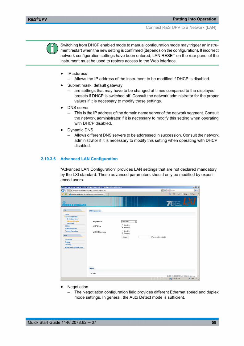
Putting into OperationR&S®UPV
58Quick Start Guide 1146.2078.62 ─ 07
Switching from DHCP enabled mode to manual configuration mode may trigger an instru-ment restart when the new setting is confirmed (depends on the configuration). If incorrectnetwork configuration settings have been entered, LAN RESET on the rear panel of theinstrument must be used to restore access to the Web interface.
● IP address– Allows the IP address of the instrument to be modified if DHCP is disabled.
● Subnet mask, default gateway– are settings that may have to be changed at times compared to the displayed
presets if DHCP is switched off. Consult the network administrator for the propervalues if it is necessary to modify these settings.
● DNS server– This is the IP address of the domain name server of the network segment. Consult
the network administrator if it is necessary to modify this setting when operatingwith DHCP disabled.
● Dynamic DNS– Allows different DNS servers to be addressed in succession. Consult the network
administrator if it is necessary to modify this setting when operating with DHCPdisabled.
2.10.3.6 Advanced LAN Configuration
"Advanced LAN Configuration" provides LAN settings that are not declared mandatoryby the LXI standard. These advanced parameters should only be modified by experi-enced users.
● Negotiation– The Negotiation configuration field provides different Ethernet speed and duplex
mode settings. In general, the Auto Detect mode is sufficient.
Connect R&S UPV to a Network (LAN)
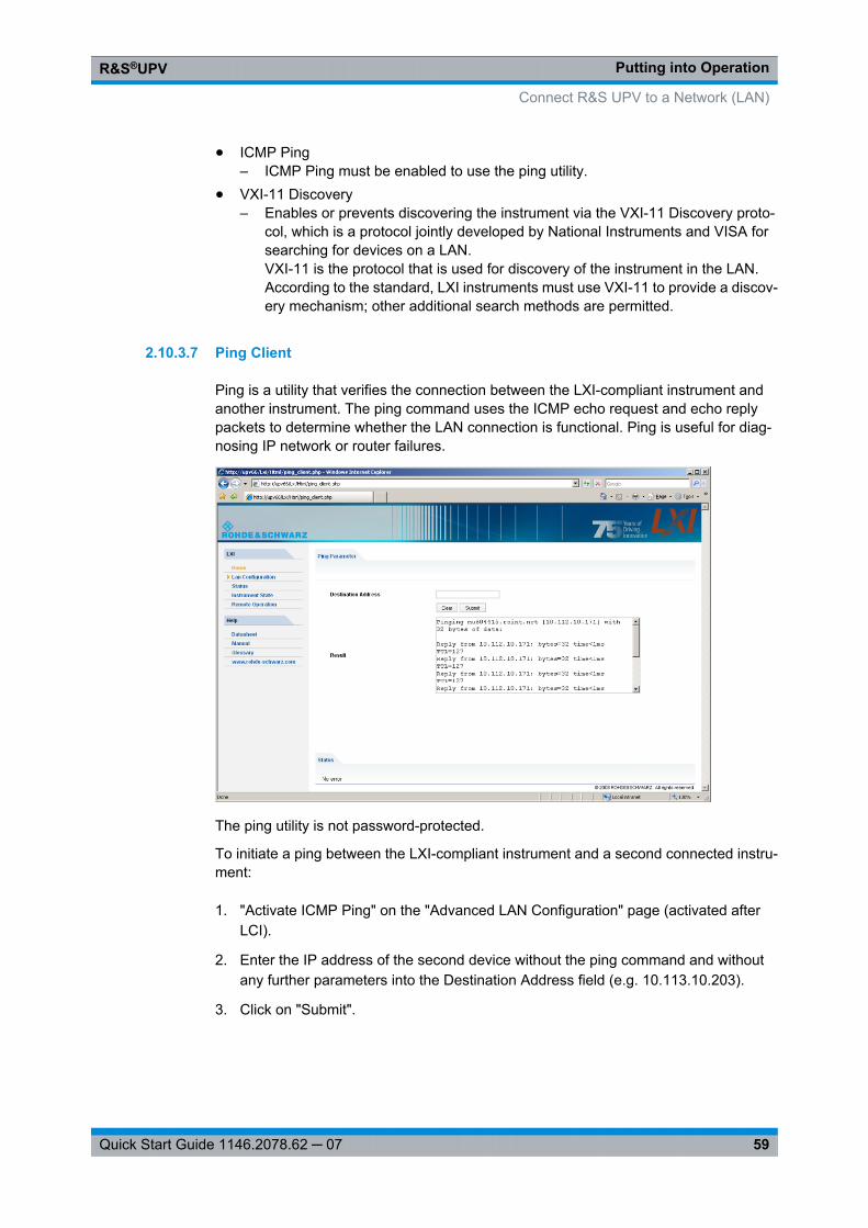
Putting into OperationR&S®UPV
59Quick Start Guide 1146.2078.62 ─ 07
● ICMP Ping– ICMP Ping must be enabled to use the ping utility.
● VXI-11 Discovery– Enables or prevents discovering the instrument via the VXI-11 Discovery proto-
col, which is a protocol jointly developed by National Instruments and VISA forsearching for devices on a LAN.VXI-11 is the protocol that is used for discovery of the instrument in the LAN.According to the standard, LXI instruments must use VXI-11 to provide a discov-ery mechanism; other additional search methods are permitted.
2.10.3.7 Ping Client
Ping is a utility that verifies the connection between the LXI-compliant instrument andanother instrument. The ping command uses the ICMP echo request and echo replypackets to determine whether the LAN connection is functional. Ping is useful for diag-nosing IP network or router failures.
The ping utility is not password-protected.
To initiate a ping between the LXI-compliant instrument and a second connected instru-ment:
1. "Activate ICMP Ping" on the "Advanced LAN Configuration" page (activated afterLCI).
2. Enter the IP address of the second device without the ping command and withoutany further parameters into the Destination Address field (e.g. 10.113.10.203).
3. Click on "Submit".
Connect R&S UPV to a Network (LAN)
Putting into OperationR&S®UPV
60Quick Start Guide 1146.2078.62 ─ 07
2.10.4 Configuration for manual remote operation
The R&S UPV can be operated manually from an external computer via a network con-nection. The Windows program Remote Desktop Connection is used for operation, see chapter 4.16, "Manual Remote Operation", on page 192.
Manual remote control of the audio analyzer is possible under the following conditions:
● the Windows 95 operating system or higher and the Remote Desktop Connectionprogram are installed on the external computer and a LAN interface is configured forthe network
● the audio analyzer and the computer are connected via LAN (see chapter 2.10.2,"Configuration of R&S UPV for Network Operation", on page 48),
● the Remote Desktop Connection program is activated on the audio analyzer (see chapter 2.10.4.1, "Activating the Remote Desktop Connection program at the R&SUPV", on page 60),
● on the external computer, the R&S UPV data have been entered in the RemoteDesktop Connection program (IP address or computer name of R&S UPV in the net-work (see chapter 2.10.2.3, "Querying the computer name", on page 52),
● the login at the external computer for R&S UPV was performed with the correct username (instrument) and the correct password (instrument) (see chapter 2.10.4.2,"Starting manual remote operation at the external computer", on page 61).
2.10.4.1 Activating the Remote Desktop Connection program at the R&S UPV
Unauthorized access possible to audio analyzerAfter activating Remote Desktop, access to this R&S UPV is possible for any user in thenetwork who knows the computer name and the login data of the audio analyzer.
Activating Remote Desktop
1. "Start – Settings – Control Panel": Click on "Performance and Maintenance".
2. "Click on System" and select "Remote" in the tab menu.
3. Activate the "Allow users to connect remotely to this computer" check box.
Connect R&S UPV to a Network (LAN)
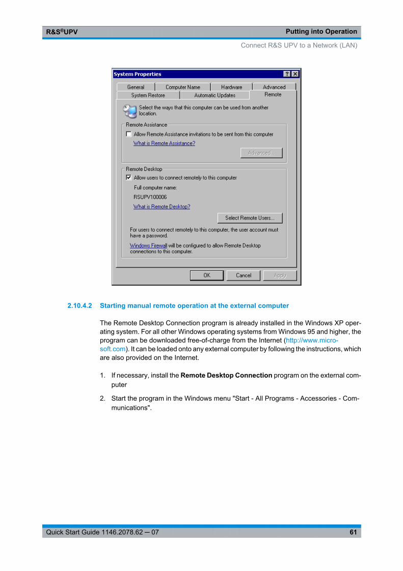
Putting into OperationR&S®UPV
61Quick Start Guide 1146.2078.62 ─ 07
2.10.4.2 Starting manual remote operation at the external computer
The Remote Desktop Connection program is already installed in the Windows XP oper-ating system. For all other Windows operating systems from Windows 95 and higher, theprogram can be downloaded free-of-charge from the Internet (http://www.micro-soft.com). It can be loaded onto any external computer by following the instructions, whichare also provided on the Internet.
1. If necessary, install the Remote Desktop Connection program on the external com-puter
2. Start the program in the Windows menu "Start - All Programs - Accessories - Com-munications".
Connect R&S UPV to a Network (LAN)
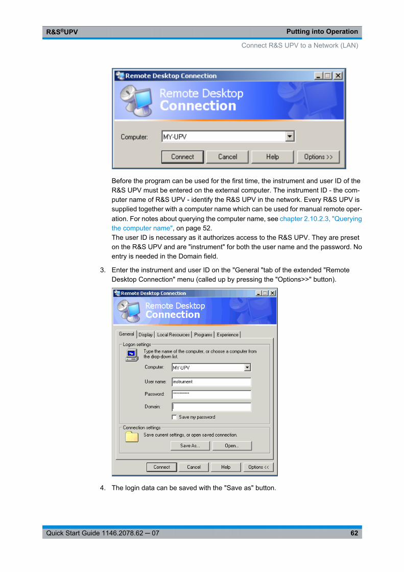
Putting into OperationR&S®UPV
62Quick Start Guide 1146.2078.62 ─ 07
Before the program can be used for the first time, the instrument and user ID of theR&S UPV must be entered on the external computer. The instrument ID - the com-puter name of R&S UPV - identify the R&S UPV in the network. Every R&S UPV issupplied together with a computer name which can be used for manual remote oper-ation. For notes about querying the computer name, see chapter 2.10.2.3, "Queryingthe computer name", on page 52.The user ID is necessary as it authorizes access to the R&S UPV. They are preseton the R&S UPV and are "instrument" for both the user name and the password. Noentry is needed in the Domain field.
3. Enter the instrument and user ID on the "General "tab of the extended "RemoteDesktop Connection" menu (called up by pressing the "Options>>" button).
4. The login data can be saved with the "Save as" button.
Connect R&S UPV to a Network (LAN)
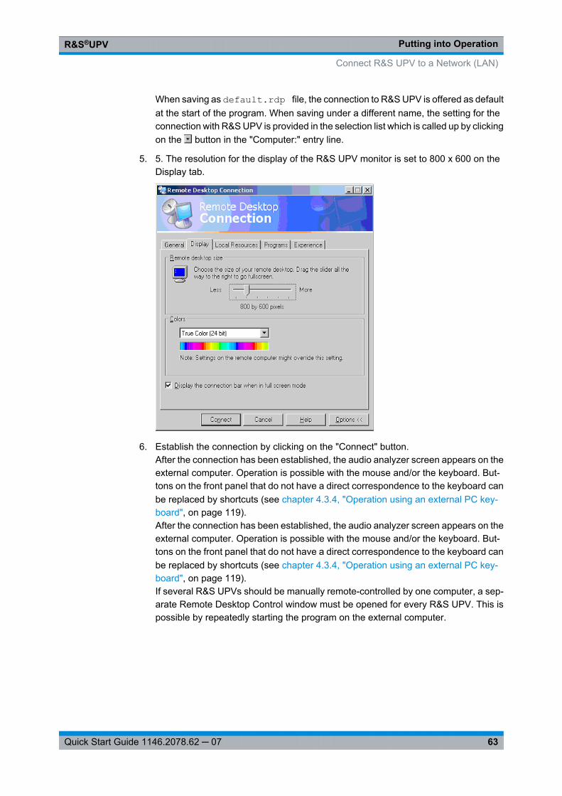
Putting into OperationR&S®UPV
63Quick Start Guide 1146.2078.62 ─ 07
When saving as default.rdp file, the connection to R&S UPV is offered as defaultat the start of the program. When saving under a different name, the setting for theconnection with R&S UPV is provided in the selection list which is called up by clickingon the button in the "Computer:" entry line.
5. 5. The resolution for the display of the R&S UPV monitor is set to 800 x 600 on theDisplay tab.
6. Establish the connection by clicking on the "Connect" button.After the connection has been established, the audio analyzer screen appears on theexternal computer. Operation is possible with the mouse and/or the keyboard. But-tons on the front panel that do not have a direct correspondence to the keyboard canbe replaced by shortcuts (see chapter 4.3.4, "Operation using an external PC key-board", on page 119).After the connection has been established, the audio analyzer screen appears on theexternal computer. Operation is possible with the mouse and/or the keyboard. But-tons on the front panel that do not have a direct correspondence to the keyboard canbe replaced by shortcuts (see chapter 4.3.4, "Operation using an external PC key-board", on page 119).If several R&S UPVs should be manually remote-controlled by one computer, a sep-arate Remote Desktop Control window must be opened for every R&S UPV. This ispossible by repeatedly starting the program on the external computer.
Connect R&S UPV to a Network (LAN)
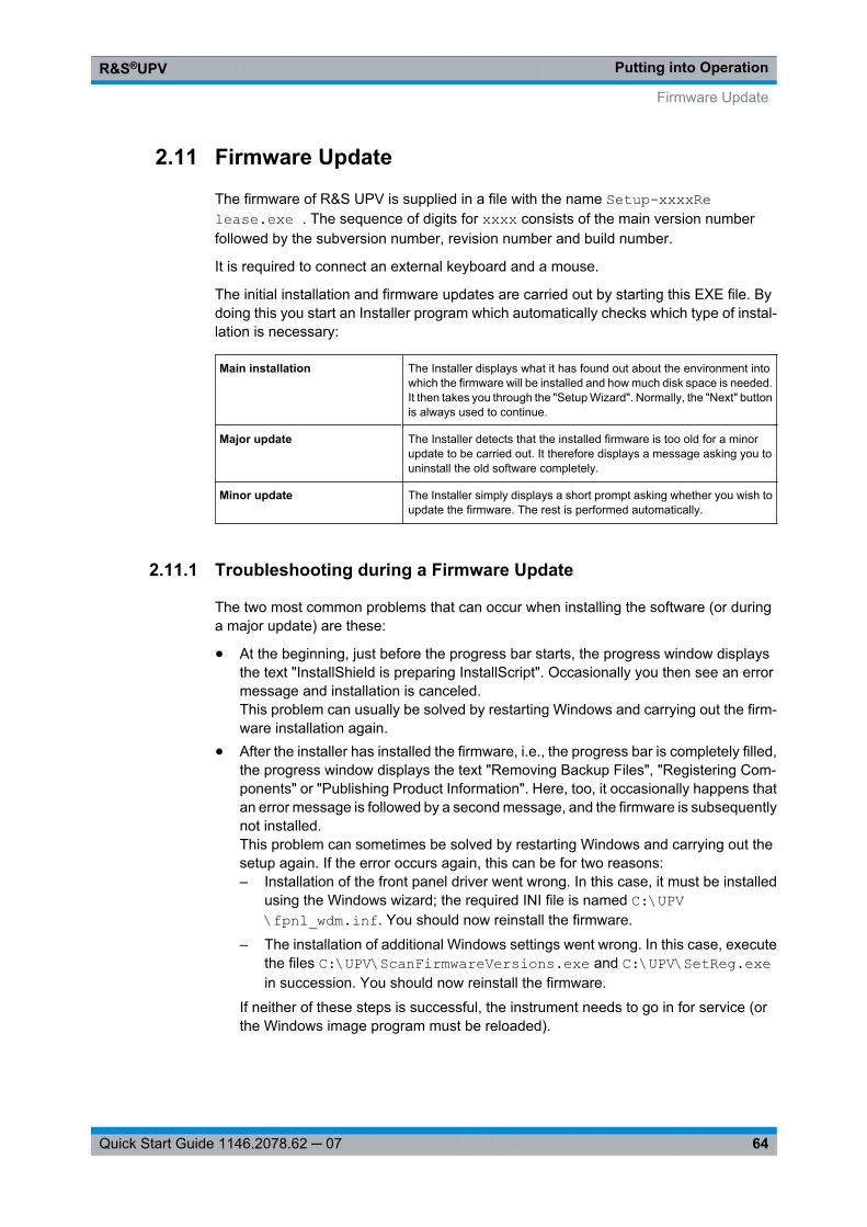
Putting into OperationR&S®UPV
64Quick Start Guide 1146.2078.62 ─ 07
2.11 Firmware Update
The firmware of R&S UPV is supplied in a file with the name Setup-xxxxRe lease.exe . The sequence of digits for xxxx consists of the main version numberfollowed by the subversion number, revision number and build number.
It is required to connect an external keyboard and a mouse.
The initial installation and firmware updates are carried out by starting this EXE file. Bydoing this you start an Installer program which automatically checks which type of instal-lation is necessary:
Main installation The Installer displays what it has found out about the environment intowhich the firmware will be installed and how much disk space is needed.It then takes you through the "Setup Wizard". Normally, the "Next" buttonis always used to continue.
Major update The Installer detects that the installed firmware is too old for a minorupdate to be carried out. It therefore displays a message asking you touninstall the old software completely.
Minor update The Installer simply displays a short prompt asking whether you wish toupdate the firmware. The rest is performed automatically.
2.11.1 Troubleshooting during a Firmware Update
The two most common problems that can occur when installing the software (or duringa major update) are these:
● At the beginning, just before the progress bar starts, the progress window displaysthe text "InstallShield is preparing InstallScript". Occasionally you then see an errormessage and installation is canceled.This problem can usually be solved by restarting Windows and carrying out the firm-ware installation again.
● After the installer has installed the firmware, i.e., the progress bar is completely filled,the progress window displays the text "Removing Backup Files", "Registering Com-ponents" or "Publishing Product Information". Here, too, it occasionally happens thatan error message is followed by a second message, and the firmware is subsequentlynot installed.This problem can sometimes be solved by restarting Windows and carrying out thesetup again. If the error occurs again, this can be for two reasons:– Installation of the front panel driver went wrong. In this case, it must be installed
using the Windows wizard; the required INI file is named C:\UPV\fpnl_wdm.inf. You should now reinstall the firmware.
– The installation of additional Windows settings went wrong. In this case, executethe files C:\UPV\ScanFirmwareVersions.exe and C:\UPV\SetReg.exein succession. You should now reinstall the firmware.
If neither of these steps is successful, the instrument needs to go in for service (orthe Windows image program must be reloaded).
Firmware Update
Putting into OperationR&S®UPV
65Quick Start Guide 1146.2078.62 ─ 07
2.12 Windows XP Recovery and Backup
The R&S UPV provides an invisible backup and recovery partition. A backup of the factorysystem partition (C:\) is saved by default and can be restored in case of a system crash.
In addition, backups of up to 5 firmware versions can be stored on this partition. It is e.g.possible to backup the current system partition prior to a firmware update or to providedifferent system configurations for different environments.
For the R&S UPV, the use of an external keyboard is recommended.
The operation is described with respect to an external keyboard. It is recommended toconnect a mouse that allows an intuitive operation!
During restore, the system partition (C:\) is deleted, formatted and rewritten. The datapartition (D:\) is not affected by this.
2.12.1 Calling the Windows XP Recovery and Backup Partition Menu
If several backups are already stored on the disk, the remaining space might not besufficient for an additional backup. In this case a warning is indicated in the Windows XPRecovery and Backup Partition menu and the user is requested to remove an old backupbefore making a new one.
1. Switch the instrument off and on again Press the cursor keys multiple times duringthe boot phase to ensure that the Boot menu does not independently close aftera short period of time.
2. In the Boot menu, use the cursor keys to select the"Backup/Recovery" line.
3. Open the "Windows XP Recovery and Backup Partition" menu with ENTER.
The menu shows the available selections for the recovery and backup partition:
Windows XP Recovery and Backup
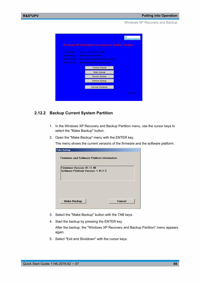
Putting into OperationR&S®UPV
66Quick Start Guide 1146.2078.62 ─ 07
2.12.2 Backup Current System Partition
1. In the Windows XP Recovery and Backup Partition menu, use the cursor keys toselect the "Make Backup" button.
2. Open the "Make Backup" menu with the ENTER key.
The menu shows the current versions of the firmware and the software platform.
3. Select the "Make Backup" button with the TAB keys.
4. Start the backup by pressing the ENTER key.
After the backup, the "Windows XP Recovery and Backup Partition" menu appearsagain.
5. Select "Exit and Shutdown" with the cursor keys.
Windows XP Recovery and Backup
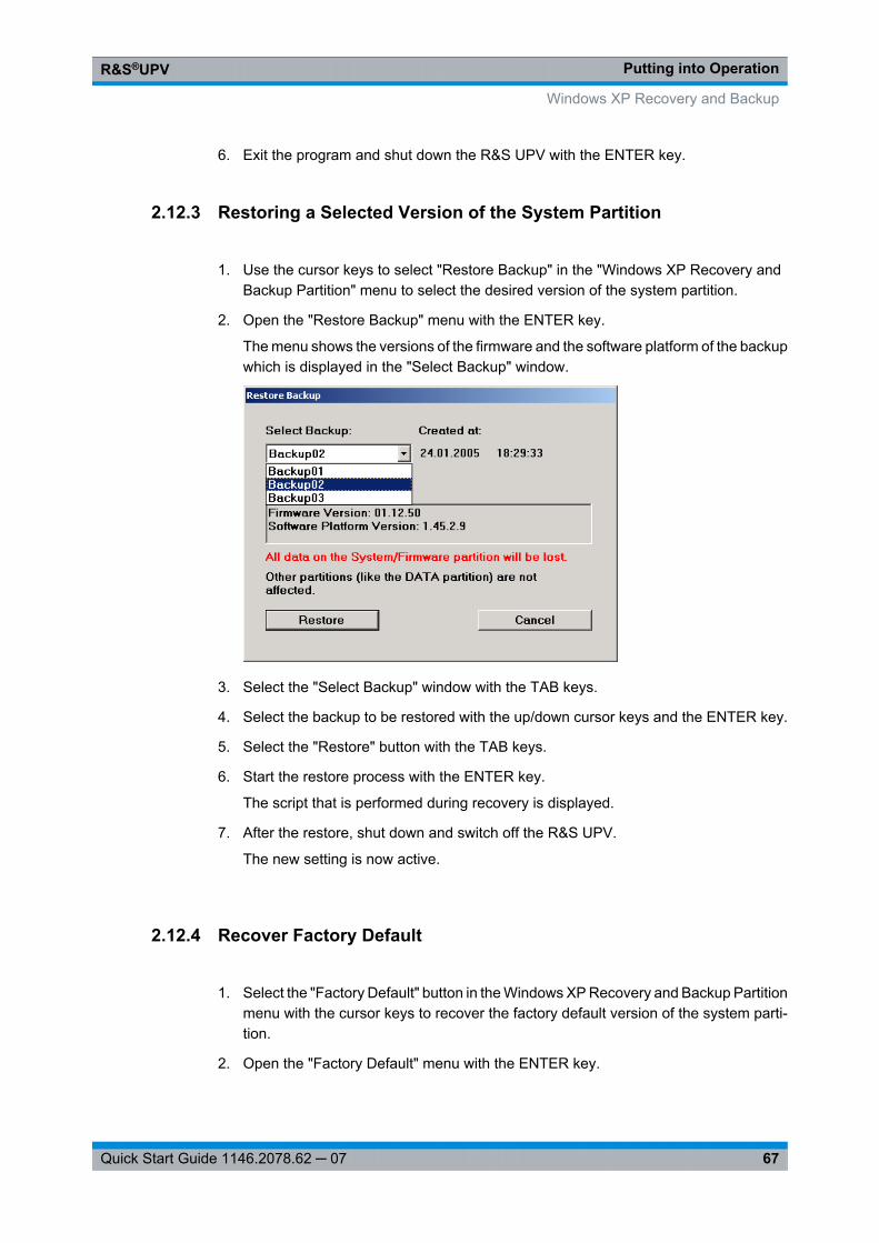
Putting into OperationR&S®UPV
67Quick Start Guide 1146.2078.62 ─ 07
6. Exit the program and shut down the R&S UPV with the ENTER key.
2.12.3 Restoring a Selected Version of the System Partition
1. Use the cursor keys to select "Restore Backup" in the "Windows XP Recovery andBackup Partition" menu to select the desired version of the system partition.
2. Open the "Restore Backup" menu with the ENTER key.
The menu shows the versions of the firmware and the software platform of the backupwhich is displayed in the "Select Backup" window.
3. Select the "Select Backup" window with the TAB keys.
4. Select the backup to be restored with the up/down cursor keys and the ENTER key.
5. Select the "Restore" button with the TAB keys.
6. Start the restore process with the ENTER key.
The script that is performed during recovery is displayed.
7. After the restore, shut down and switch off the R&S UPV.
The new setting is now active.
2.12.4 Recover Factory Default
1. Select the "Factory Default" button in the Windows XP Recovery and Backup Partitionmenu with the cursor keys to recover the factory default version of the system parti-tion.
2. Open the "Factory Default" menu with the ENTER key.
Windows XP Recovery and Backup
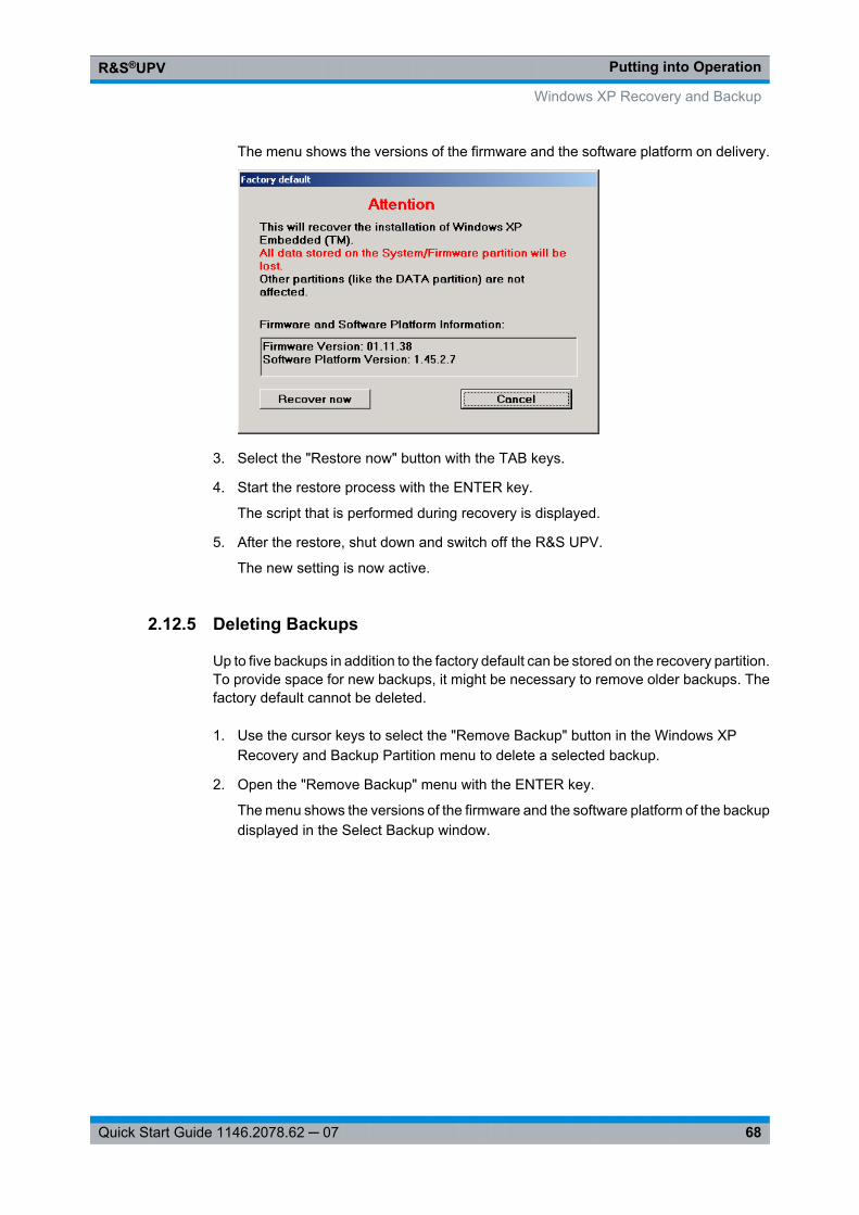
Putting into OperationR&S®UPV
68Quick Start Guide 1146.2078.62 ─ 07
The menu shows the versions of the firmware and the software platform on delivery.
3. Select the "Restore now" button with the TAB keys.
4. Start the restore process with the ENTER key.
The script that is performed during recovery is displayed.
5. After the restore, shut down and switch off the R&S UPV.
The new setting is now active.
2.12.5 Deleting Backups
Up to five backups in addition to the factory default can be stored on the recovery partition.To provide space for new backups, it might be necessary to remove older backups. Thefactory default cannot be deleted.
1. Use the cursor keys to select the "Remove Backup" button in the Windows XPRecovery and Backup Partition menu to delete a selected backup.
2. Open the "Remove Backup" menu with the ENTER key.
The menu shows the versions of the firmware and the software platform of the backupdisplayed in the Select Backup window.
Windows XP Recovery and Backup
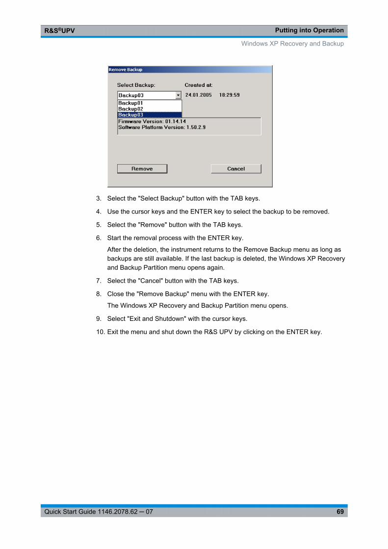
Putting into OperationR&S®UPV
69Quick Start Guide 1146.2078.62 ─ 07
3. Select the "Select Backup" button with the TAB keys.
4. Use the cursor keys and the ENTER key to select the backup to be removed.
5. Select the "Remove" button with the TAB keys.
6. Start the removal process with the ENTER key.
After the deletion, the instrument returns to the Remove Backup menu as long asbackups are still available. If the last backup is deleted, the Windows XP Recoveryand Backup Partition menu opens again.
7. Select the "Cancel" button with the TAB keys.
8. Close the "Remove Backup" menu with the ENTER key.
The Windows XP Recovery and Backup Partition menu opens.
9. Select "Exit and Shutdown" with the cursor keys.
10. Exit the menu and shut down the R&S UPV by clicking on the ENTER key.
Windows XP Recovery and Backup

Getting StartedR&S®UPV
71Quick Start Guide 1146.2078.62 ─ 07
3 Getting Started
3.1 Introduction - Getting Started
This chapter describes the manual operation of the R&S UPV audio analyzer. The infor-mation in this chapter also largely applies analogously to the R&S UPV66(which wasprimarily designed for system use) provided that an external monitor, keyboard, andmouse are connected to the instrument. For more detailed information on the operationvia external keyboard and mouse, see chapter 4, "Manual Operation", on page 109.
The R&S UPV audio analyzer is able to perform virtually all measurements occurring inthe audio world, from frequency response measurements through distortion factor andspectral displays to the analysis of digital data streams. Several measurement functionscan be carried out and displayed at the same time, whereby the measurements are per-formed perfectly simultaneously at all switched-on channels.
The R&S UPV performs all measurements using digital signal processing. Here, analogsignals to be measured are first subjected to complex preprocessing on analog mea-surement modules before they are digitalized and fed to the digital measurement routines.
This concept offers numerous advantages, for example:
● The measurement methods at the analog and digital interfaces are identical.● The measurement functions are available at both the analog and the digital interfaces.● Operation at the analog and digital interfaces is the same.
The many available options mean that the R&S UPV can be adapted to perform a widevariety of different tasks. The basic version of the instrument has analog audio interfaces.A number of special measurement functions are also available, but only after the appro-priate options have been installed (see the data sheet for details).
This chapter, "Getting Started", only describes the functions available in the basic versionof the R&S UPV audio analyzer.
Introduction - Getting Started
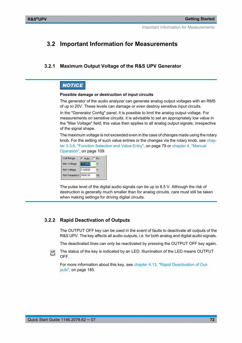
Getting StartedR&S®UPV
72Quick Start Guide 1146.2078.62 ─ 07
3.2 Important Information for Measurements
3.2.1 Maximum Output Voltage of the R&S UPV Generator
Possible damage or destruction of input circuitsThe generator of the audio analyzer can generate analog output voltages with an RMSof up to 20V. These levels can damage or even destroy sensitive input circuits.In the "Generator Config" panel, it is possible to limit the analog output voltage. Formeasurements on sensitive circuits, it is advisable to set an appropriately low value inthe "Max Voltage" field; this value then applies to all analog output signals, irrespectiveof the signal shape.The maximum voltage is not exceeded even in the case of changes made using the rotaryknob. For the setting of such value entries or the changes via the rotary knob, see chap-ter 3.3.6, "Function Selection and Value Entry", on page 79 or chapter 4, "ManualOperation", on page 109.
The pulse level of the digital audio signals can be up to 8.5 V. Although the risk ofdestruction is generally much smaller than for analog circuits, care must still be takenwhen making settings for driving digital circuits.
3.2.2 Rapid Deactivation of Outputs
The OUTPUT OFF key can be used in the event of faults to deactivate all outputs of theR&S UPV. The key affects all audio outputs, i.e. for both analog and digital audio signals.
The deactivated lines can only be reactivated by pressing the OUTPUT OFF key again.
The status of the key is indicated by an LED. Illumination of the LED means OUTPUTOFF.
For more information about this key, see chapter 4.13, "Rapid Deactivation of Out-puts", on page 185.
Important Information for Measurements
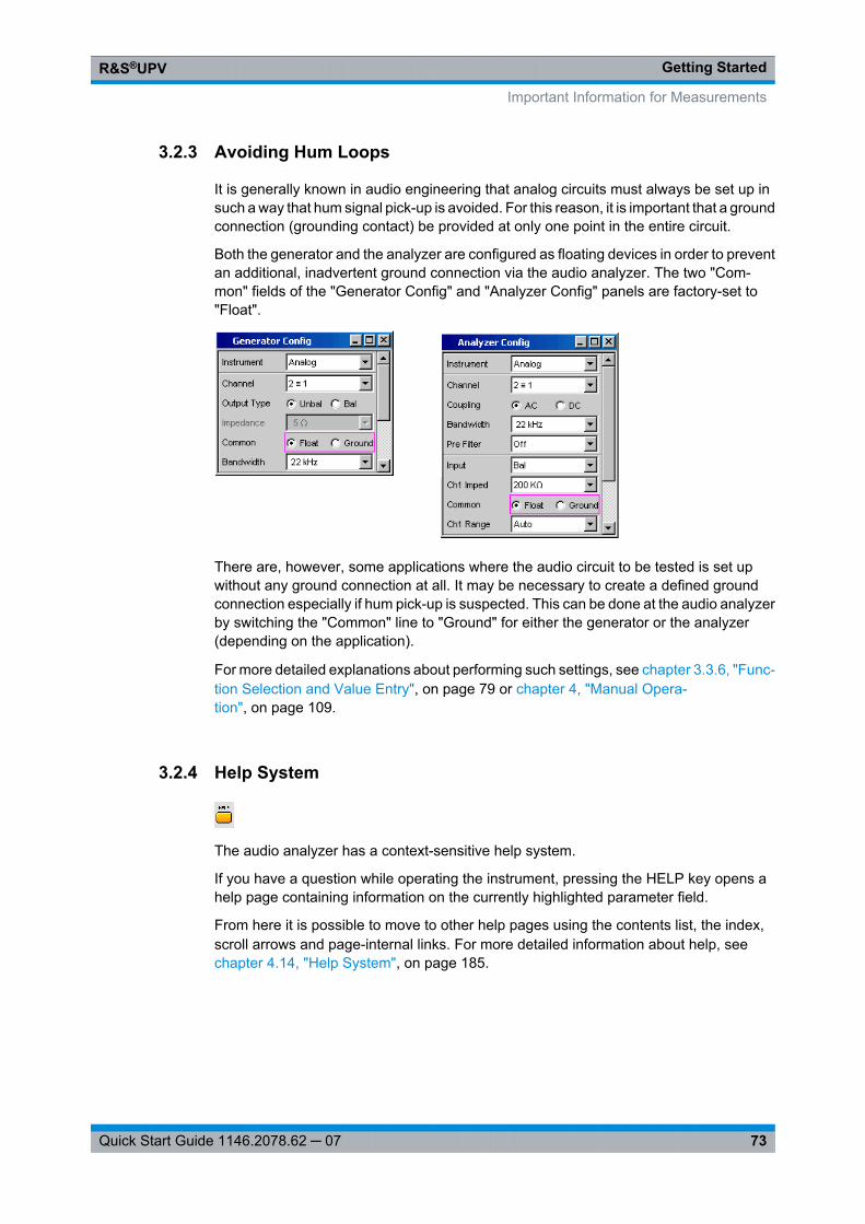
Getting StartedR&S®UPV
73Quick Start Guide 1146.2078.62 ─ 07
3.2.3 Avoiding Hum Loops
It is generally known in audio engineering that analog circuits must always be set up insuch a way that hum signal pick-up is avoided. For this reason, it is important that a groundconnection (grounding contact) be provided at only one point in the entire circuit.
Both the generator and the analyzer are configured as floating devices in order to preventan additional, inadvertent ground connection via the audio analyzer. The two "Com-mon" fields of the "Generator Config" and "Analyzer Config" panels are factory-set to"Float".
There are, however, some applications where the audio circuit to be tested is set upwithout any ground connection at all. It may be necessary to create a defined groundconnection especially if hum pick-up is suspected. This can be done at the audio analyzerby switching the "Common" line to "Ground" for either the generator or the analyzer(depending on the application).
For more detailed explanations about performing such settings, see chapter 3.3.6, "Func-tion Selection and Value Entry", on page 79 or chapter 4, "Manual Opera-tion", on page 109.
3.2.4 Help System
The audio analyzer has a context-sensitive help system.
If you have a question while operating the instrument, pressing the HELP key opens ahelp page containing information on the currently highlighted parameter field.
From here it is possible to move to other help pages using the contents list, the index,scroll arrows and page-internal links. For more detailed information about help, see chapter 4.14, "Help System", on page 185.
Important Information for Measurements
Getting StartedR&S®UPV
74Quick Start Guide 1146.2078.62 ─ 07
3.3 Brief Introduction to Operation
3.3.1 Windows User Interface and Controls
To provide the user with a familiar environment, the operation of R&S UPV is largelybased on the Windows user interfaces. All panels, entry windows, etc. are made up ofknown elements.
Operation follows the same basic rules which apply to other Windows programs in usetoday. It is assumed that the user is familiar with these basic rules. This information istherefore not given in detail in this manual.
The R&S UPV can be operated via the front panel. Additional peripherals such as amouse and keyboard can be connected, but are not essential requirements. The R&SUPV66 can be operated manually, provided that an external monitor, an external key-board and a mouse are connected.
After being switched on, the instrument is in the same state as it was before it wasswitched off. This applies to all setting parameters of the R&S UPV, including those notcurrently displayed on the screen.
The instrument is operated using function keys with permanently assigned functions,softkeys with functions which vary according to the application, the rotary knob with inte-grated entry function, and the display screen via which the panels are operated.
Operation using an external keyboard or mouse is also possible; this is explained in chapter 4, "Manual Operation", on page 109.
Selection frames or the highlighting of an entry field (dark background) indicate the cur-rent entry focus. Entries can be made in the element with entry focus.
3.3.2 The Display
The display is the central element for manually operating the R&S UPV. Both the instru-ment settings in the various panels, and the measurement results are displayed here.
To make the various functions of the R&S UPV audio analyzer easier to operate, theyare organized in a series of panels. The measurement results can be displayed as digitalnumeric values, data lists, in analog bar graphs or in result graphics. The user can freelychoose the number of panels and the number of graphical windows to be shown in thedisplay. The size of the windows can be changed within wide limits, whereby the fontsize, scaling and so on are adapted automatically (depending on the selected window).
Panels and display windows can be activated by pressing the WINBAR key.
Five display windows (or "screens") are provided so that the wealth of information canbe better organized. The direction keys are used to toggle between the individualscreens.
Brief Introduction to Operation

Getting StartedR&S®UPV
75Quick Start Guide 1146.2078.62 ─ 07
Fig. 3-1: Screen with the essential elements
1 = Panel2 = Menu bar3 = Numeric display4 = Graphical window5 = Hidden panels6 = WINBAR7 = Softkeys
One of the two bars (either the softkey bar or the WINBAR) is always displayed at thebottom of the screen.
In normal operating mode, the softkey bar is visible; it contains eight buttons which areassigned the functions available in the selection windows of the panels.
If there are more than 8 elements to choose from, the hidden elements in the selectionlist can be displayed by pressing the last softkey containing the >> symbol or the firstsoftkey containing the << symbol.
When the WINBAR key is pressed, the WINBAR appears in place of the softkey bar; thisis indicated by "Panel List" in the left-hand corner:
The labeled buttons show the names of all panels and graphical windows open in thecurrent screen. Pressing the associated softkey puts the focus on the correspondingpanel / graphical window, i.e. it becomes active. At the same time, the system returns tonormal operating mode (i.e. the softkey bar).
Brief Introduction to Operation
Getting StartedR&S®UPV
76Quick Start Guide 1146.2078.62 ─ 07
Hidden panels (see chapter 3.3.3, "Panels and Display Windows", on page 76) are alsolisted in the WINBAR. If a hidden panel is selected, it is redisplayed on the screen withits previously set size and position; it simultaneously receives the focus.
3.3.3 Panels and Display Windows
The R&S UPV audio analyzer distinguishes between the following panels and displaywindows:
● Panels used to perform function settings.● Configuration panels used for configuring how the measurement values are to be
displayed.● Numeric display fields for displaying the measurement values of the various mea-
surement functions.● Combo displays in which numeric measurement values can be supplemented by
bar graphs and limit monitoring.● Graphical windows in which measurement values are displayed in the form of dia-
grams.● Data lists in which the measurement values are listed in tabular form.
Panels are opened on the currently displayed screen by activating the menu bar usingthe MENU key, highlighting the "Instruments" or "DispConfig" button with the rotary knobor cursor keys, opening the pull-down menu with the Enter key or rotary-knob click, andthen highlighting the desired panel and selecting it with a rotary-knob click.
Display windows are selected in the same way, except that they are listed under the"Displays" menu item.
Each panel and display window is a separate window which can be either closed, openedor hidden. Panels/display windows are open if they are visible on the currently displayedscreen; If the panel size is minimized and moved to the bottom edge of the screen, it isreferred to as hidden.
In both cases, the panel / window is assigned an entry in the WINBAR at the bottom ofthe display. Only one window on the screen can be activated at any one time using thesoftkeys on the WINBAR (active windows are identified by their blue title bar).
As soon as a panel / display window is active, it can be moved around on the screen.This is done in the following way:
► After clicking on theMODIFY button, the following softkey labeling appears on theWINBAR:
After selecting the desired direction of movement using the appropriate softkey, thepanel can be moved / resized using the rotary knob.
Brief Introduction to Operation
Getting StartedR&S®UPV
77Quick Start Guide 1146.2078.62 ─ 07
The same panel / display window can be displayed in several screens at the same time.The display characteristics can be different for each of the screens; the content is, how-ever, always the same.
3.3.4 Structure of the Panels and Display Windows
The R&S UPV audio analyzer features the following panels with their main settings (fora detailed list of all panels with the most important setting parameters, see chapter 4,"Manual Operation", on page 109).
Panels which can be selected via the "Instruments" menu bar button:
Generator Config ● Selection of instrument (analog or digital interfaces)● Configuration of channels and bandwidths● Reference values
Generator Function ● Selection of test signals● Sweep function● Frequency and level settings● Filter and equalizer● DC Offset
Analyzer Config ● Selection of instrument (analog or digital interfaces)● Configuration of channels, measuring bandwidth and pre-filter● Range configuration● Reference values● Start and trigger conditions
Analyzer Function ● Selection of measurement functions● Measurement speed and accuracy● Activation of filter and equalizer● Activation of Post-FFT● Selection and settings for level monitor● Selection and settings for input monitor● Selection and settings for frequency, phase, group delay measurement● Selection and settings for waveform monitor
Filters ● Definition of filter properties
Auxiliaries ● Settings for integrated loudspeaker and connected headphones● Settings for R&S UPV-U2 BNC audio monitoring outputs● Settings for auxiliary analog output● Settings for trigger input and trigger output
Switcher Panel ● Operation of one or more R&S UPZ audio switchers
Protocol Generator ● Settings for the R&S UPV-K21 option (digital audio protocol)
Panels which can be selected via the "DispConfig" menu bar button:
Brief Introduction to Operation
Getting StartedR&S®UPV
78Quick Start Guide 1146.2078.62 ─ 07
Function Config
Level Monitor
Config
Input Config
Freq Phase Config
These four panels contain settings for displaying measurement values● in the numeric display fields● in the associated combo displays● and settings for limits, minimum values and maximum values
Sweep Graph Config
Impulse Response
FFT Graph Config
Waveform Config
PESQ/POLQA
Bar Graph Config
Up to four of each of these panels are available; they contain settings for displayingmeasurement values in the graphical windows, e.g.● one or two-channel display● units, scaling, grid lines, etc.● Evaluation of minimum and maximum values● Entry of limit curves● Settings for cursors and markers
The measurement results of the audio analyzer are shown in the following display win-dows (for a detailed list of all panels with the most important setting parameters, see chapter 4, "Manual Operation", on page 109).
Except for the Dig Analyzer Protocol window, the panels can be selected via the "Dis-plays" button in the menu bar:
Numeric Display ● Display of measurement results for measurement function selected in Ana-lyzer Function panel
● Display of measurement results for level monitor and/or input monitor selectedin Analyzer Function panel
● Frequency measurement results, or frequency measurement result andphase / group delay measurement result
Funct Ch1 to Ch2
Lev Mon Ch1 to Ch2
Input Ch1 to Ch2
Freq Ch1
Freq / Phase
These combo displays are extensions to the numeric measurement displays; theyshow the respective numeric value plus the following additional features:● Analog bar graphs● Limits● Minimum and maximum values
Sweep Graph 1…4
Impulse Response
FFT Graph 1…2
Waveform
PESQ/POLQA
Bar Graph 1…2
● Up to four of each of these display windows can be opened (depending on thewindow type) in order to display the scans of the different measurements
● Graphical display shows one or two channels● The measurement results are displayed in the way defined in the associated
configuration panel
Dig Analyzer Protocol ● The analyzed data of the digital audio protocol is displayed here (R&S UPV-K21 (option)
3.3.5 Basic Rules of Operation
The following basic rules are intended to simplify operation of the audio analyzer:
● Operating sequence in the panels from top to bottom
Brief Introduction to Operation
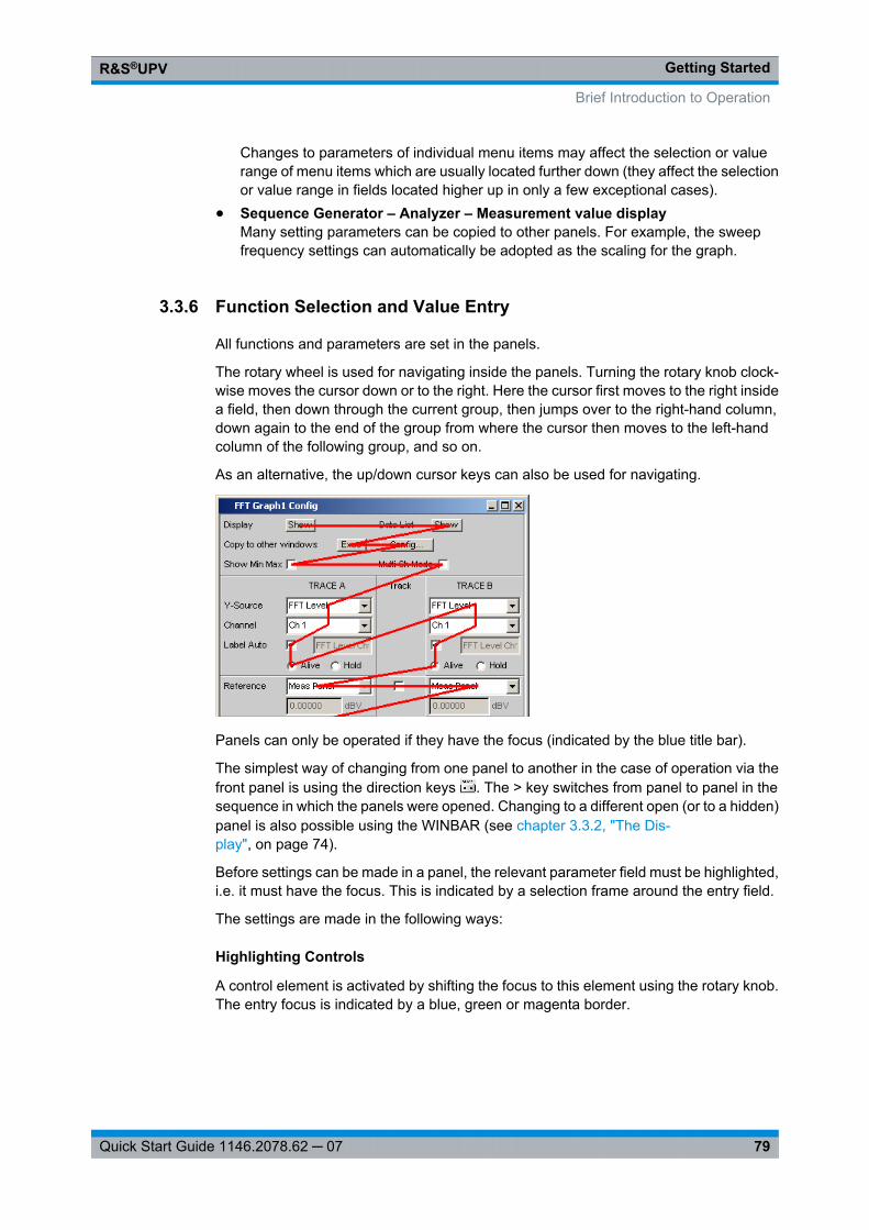
Getting StartedR&S®UPV
79Quick Start Guide 1146.2078.62 ─ 07
Changes to parameters of individual menu items may affect the selection or valuerange of menu items which are usually located further down (they affect the selectionor value range in fields located higher up in only a few exceptional cases).
● Sequence Generator – Analyzer – Measurement value displayMany setting parameters can be copied to other panels. For example, the sweepfrequency settings can automatically be adopted as the scaling for the graph.
3.3.6 Function Selection and Value Entry
All functions and parameters are set in the panels.
The rotary wheel is used for navigating inside the panels. Turning the rotary knob clock-wise moves the cursor down or to the right. Here the cursor first moves to the right insidea field, then down through the current group, then jumps over to the right-hand column,down again to the end of the group from where the cursor then moves to the left-handcolumn of the following group, and so on.
As an alternative, the up/down cursor keys can also be used for navigating.
Panels can only be operated if they have the focus (indicated by the blue title bar).
The simplest way of changing from one panel to another in the case of operation via thefront panel is using the direction keys . The > key switches from panel to panel in thesequence in which the panels were opened. Changing to a different open (or to a hidden)panel is also possible using the WINBAR (see chapter 3.3.2, "The Dis-play", on page 74).
Before settings can be made in a panel, the relevant parameter field must be highlighted,i.e. it must have the focus. This is indicated by a selection frame around the entry field.
The settings are made in the following ways:
Highlighting Controls
A control element is activated by shifting the focus to this element using the rotary knob.The entry focus is indicated by a blue, green or magenta border.
Brief Introduction to Operation
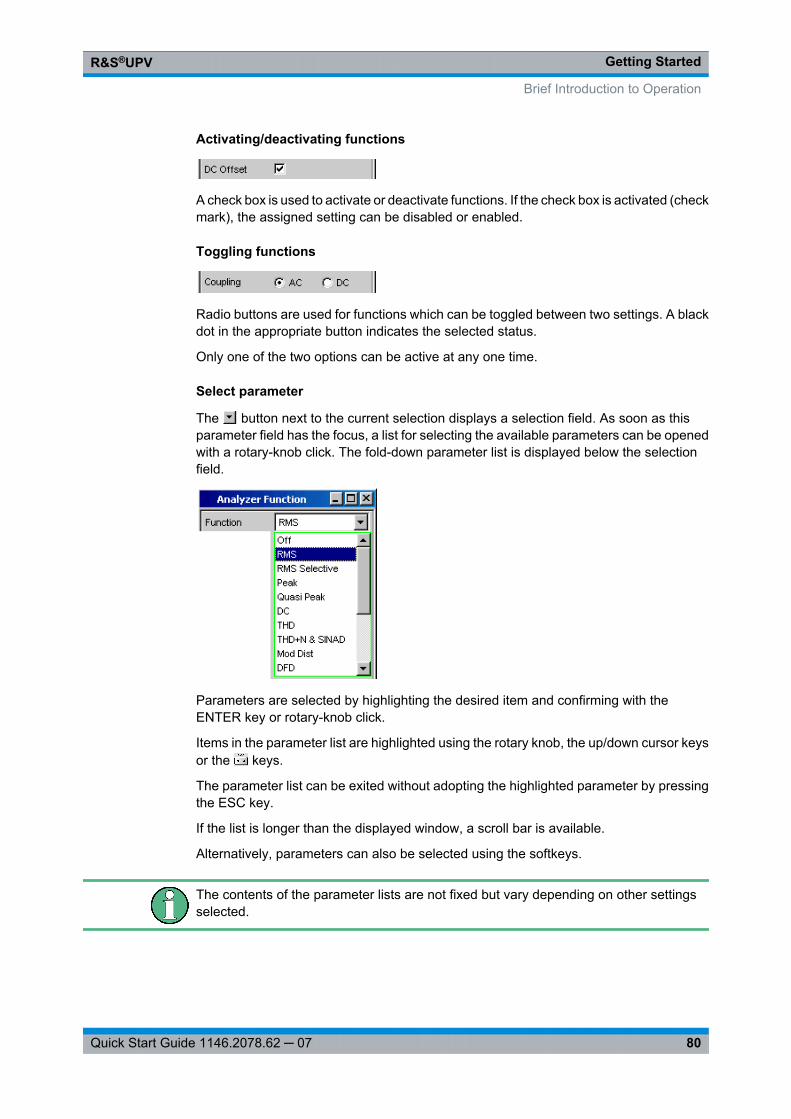
Getting StartedR&S®UPV
80Quick Start Guide 1146.2078.62 ─ 07
Activating/deactivating functions
A check box is used to activate or deactivate functions. If the check box is activated (checkmark), the assigned setting can be disabled or enabled.
Toggling functions
Radio buttons are used for functions which can be toggled between two settings. A blackdot in the appropriate button indicates the selected status.
Only one of the two options can be active at any one time.
Select parameter
The button next to the current selection displays a selection field. As soon as thisparameter field has the focus, a list for selecting the available parameters can be openedwith a rotary-knob click. The fold-down parameter list is displayed below the selectionfield.
Parameters are selected by highlighting the desired item and confirming with theENTER key or rotary-knob click.
Items in the parameter list are highlighted using the rotary knob, the up/down cursor keysor the keys.
The parameter list can be exited without adopting the highlighted parameter by pressingthe ESC key.
If the list is longer than the displayed window, a scroll bar is available.
Alternatively, parameters can also be selected using the softkeys.
The contents of the parameter lists are not fixed but vary depending on other settingsselected.
Brief Introduction to Operation
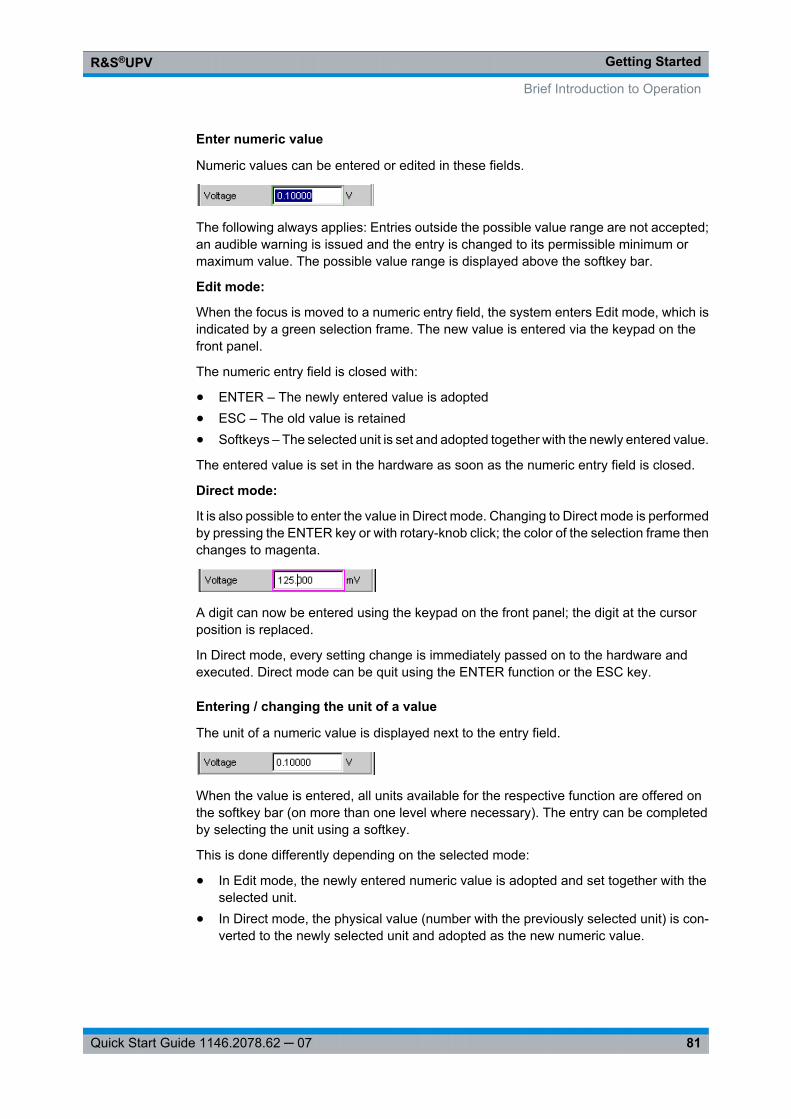
Getting StartedR&S®UPV
81Quick Start Guide 1146.2078.62 ─ 07
Enter numeric value
Numeric values can be entered or edited in these fields.
The following always applies: Entries outside the possible value range are not accepted;an audible warning is issued and the entry is changed to its permissible minimum ormaximum value. The possible value range is displayed above the softkey bar.
Edit mode:
When the focus is moved to a numeric entry field, the system enters Edit mode, which isindicated by a green selection frame. The new value is entered via the keypad on thefront panel.
The numeric entry field is closed with:
● ENTER – The newly entered value is adopted● ESC – The old value is retained● Softkeys – The selected unit is set and adopted together with the newly entered value.
The entered value is set in the hardware as soon as the numeric entry field is closed.
Direct mode:
It is also possible to enter the value in Direct mode. Changing to Direct mode is performedby pressing the ENTER key or with rotary-knob click; the color of the selection frame thenchanges to magenta.
A digit can now be entered using the keypad on the front panel; the digit at the cursorposition is replaced.
In Direct mode, every setting change is immediately passed on to the hardware andexecuted. Direct mode can be quit using the ENTER function or the ESC key.
Entering / changing the unit of a value
The unit of a numeric value is displayed next to the entry field.
When the value is entered, all units available for the respective function are offered onthe softkey bar (on more than one level where necessary). The entry can be completedby selecting the unit using a softkey.
This is done differently depending on the selected mode:
● In Edit mode, the newly entered numeric value is adopted and set together with theselected unit.
● In Direct mode, the physical value (number with the previously selected unit) is con-verted to the newly selected unit and adopted as the new numeric value.
Brief Introduction to Operation
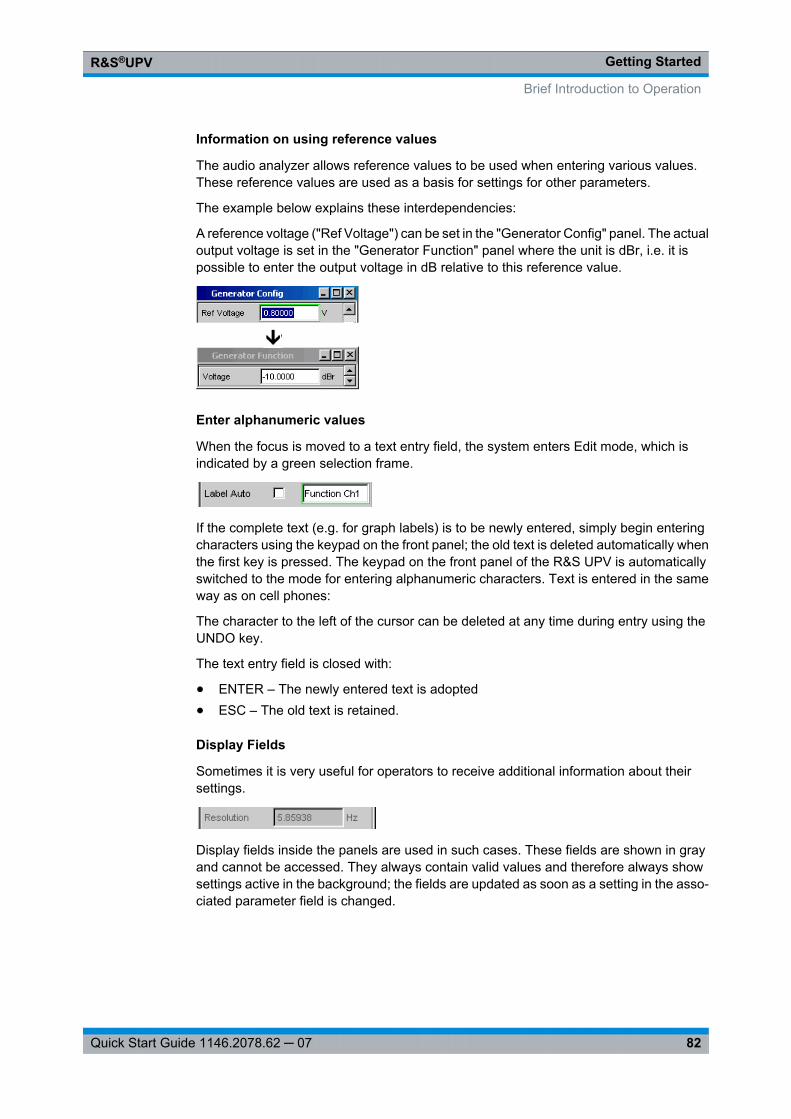
Getting StartedR&S®UPV
82Quick Start Guide 1146.2078.62 ─ 07
Information on using reference values
The audio analyzer allows reference values to be used when entering various values.These reference values are used as a basis for settings for other parameters.
The example below explains these interdependencies:
A reference voltage ("Ref Voltage") can be set in the "Generator Config" panel. The actualoutput voltage is set in the "Generator Function" panel where the unit is dBr, i.e. it ispossible to enter the output voltage in dB relative to this reference value.
Enter alphanumeric values
When the focus is moved to a text entry field, the system enters Edit mode, which isindicated by a green selection frame.
If the complete text (e.g. for graph labels) is to be newly entered, simply begin enteringcharacters using the keypad on the front panel; the old text is deleted automatically whenthe first key is pressed. The keypad on the front panel of the R&S UPV is automaticallyswitched to the mode for entering alphanumeric characters. Text is entered in the sameway as on cell phones:
The character to the left of the cursor can be deleted at any time during entry using theUNDO key.
The text entry field is closed with:
● ENTER – The newly entered text is adopted● ESC – The old text is retained.
Display Fields
Sometimes it is very useful for operators to receive additional information about theirsettings.
Display fields inside the panels are used in such cases. These fields are shown in grayand cannot be accessed. They always contain valid values and therefore always showsettings active in the background; the fields are updated as soon as a setting in the asso-ciated parameter field is changed.
Brief Introduction to Operation
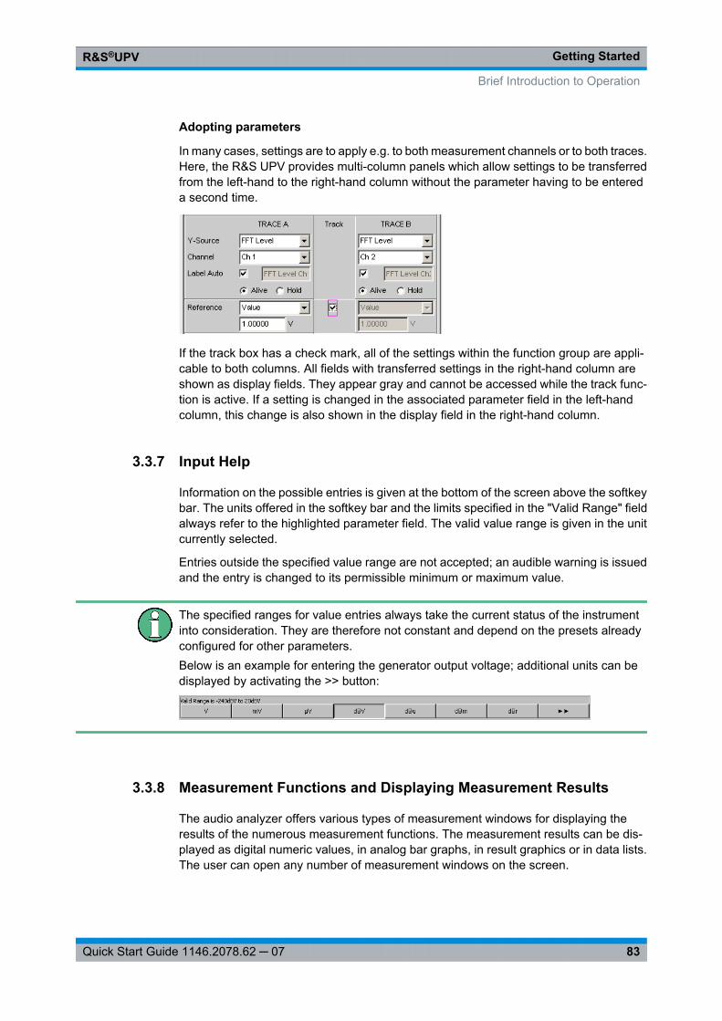
Getting StartedR&S®UPV
83Quick Start Guide 1146.2078.62 ─ 07
Adopting parameters
In many cases, settings are to apply e.g. to both measurement channels or to both traces.Here, the R&S UPV provides multi-column panels which allow settings to be transferredfrom the left-hand to the right-hand column without the parameter having to be entereda second time.
If the track box has a check mark, all of the settings within the function group are appli-cable to both columns. All fields with transferred settings in the right-hand column areshown as display fields. They appear gray and cannot be accessed while the track func-tion is active. If a setting is changed in the associated parameter field in the left-handcolumn, this change is also shown in the display field in the right-hand column.
3.3.7 Input Help
Information on the possible entries is given at the bottom of the screen above the softkeybar. The units offered in the softkey bar and the limits specified in the "Valid Range" fieldalways refer to the highlighted parameter field. The valid value range is given in the unitcurrently selected.
Entries outside the specified value range are not accepted; an audible warning is issuedand the entry is changed to its permissible minimum or maximum value.
The specified ranges for value entries always take the current status of the instrumentinto consideration. They are therefore not constant and depend on the presets alreadyconfigured for other parameters.Below is an example for entering the generator output voltage; additional units can bedisplayed by activating the >> button:
3.3.8 Measurement Functions and Displaying Measurement Results
The audio analyzer offers various types of measurement windows for displaying theresults of the numerous measurement functions. The measurement results can be dis-played as digital numeric values, in analog bar graphs, in result graphics or in data lists.The user can open any number of measurement windows on the screen.
Brief Introduction to Operation
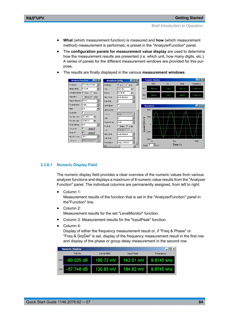
Getting StartedR&S®UPV
84Quick Start Guide 1146.2078.62 ─ 07
● What (which measurement function) is measured and how (which measurementmethod) measurement is performed, is preset in the "AnalyzerFunction" panel.
● The configuration panels for measurement value display are used to determinehow the measurement results are presented (i.e. which unit, how many digits, etc.).A series of panels for the different measurement windows are provided for this pur-pose.
● The results are finally displayed in the various measurement windows.
3.3.8.1 Numeric Display Field
The numeric display field provides a clear overview of the numeric values from variousanalyzer functions and displays a maximum of 8 numeric value results from the "AnalyzerFunction" panel. The individual columns are permanently assigned, from left to right:
● Column 1:Measurement results of the function that is set in the "AnalyzerFunction" panel inthe"Function" line.
● Column 2:Measurement results for the set "LevelMonitor" function.
● Column 3: Measurement results for the "InputPeak" function.● Column 4:
Display of either the frequency measurement result or, if "Freq & Phase" or"Freq & GrpDel" is set, display of the frequency measurement result in the first rowand display of the phase or group delay measurement in the second row.
Brief Introduction to Operation
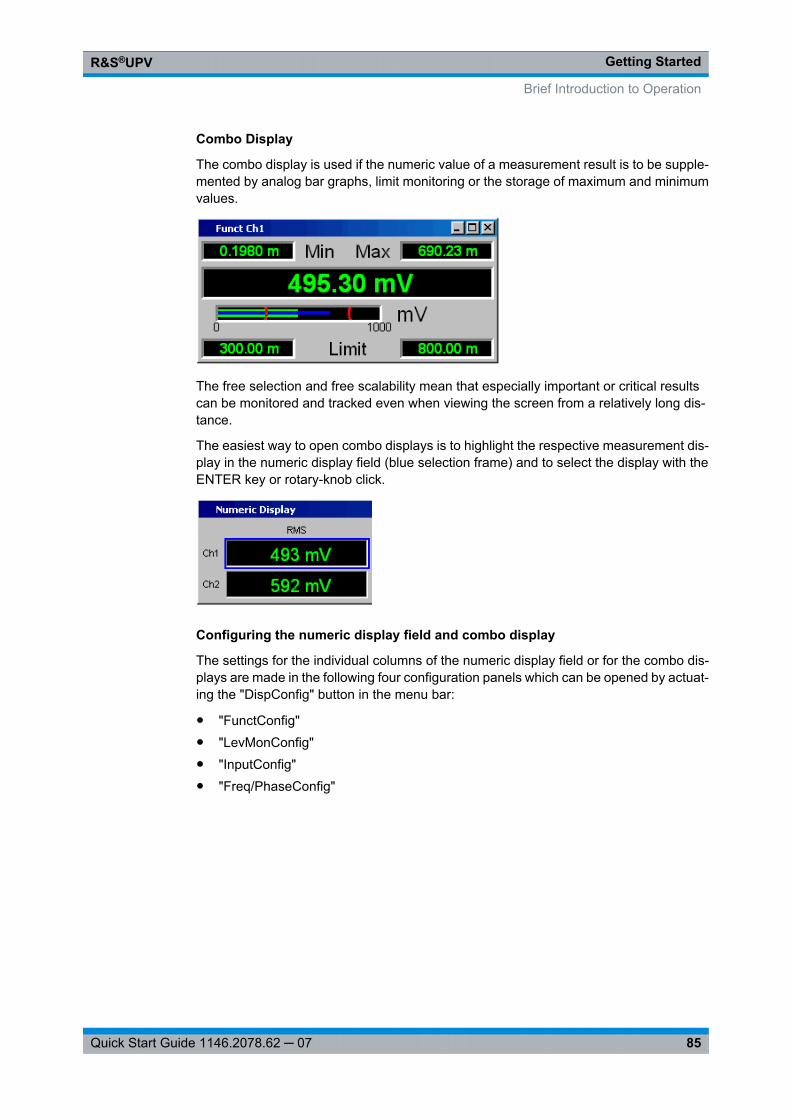
Getting StartedR&S®UPV
85Quick Start Guide 1146.2078.62 ─ 07
Combo Display
The combo display is used if the numeric value of a measurement result is to be supple-mented by analog bar graphs, limit monitoring or the storage of maximum and minimumvalues.
The free selection and free scalability mean that especially important or critical resultscan be monitored and tracked even when viewing the screen from a relatively long dis-tance.
The easiest way to open combo displays is to highlight the respective measurement dis-play in the numeric display field (blue selection frame) and to select the display with theENTER key or rotary-knob click.
Configuring the numeric display field and combo display
The settings for the individual columns of the numeric display field or for the combo dis-plays are made in the following four configuration panels which can be opened by actuat-ing the "DispConfig" button in the menu bar:
● "FunctConfig"● "LevMonConfig"● "InputConfig"● "Freq/PhaseConfig"
Brief Introduction to Operation

Getting StartedR&S®UPV
86Quick Start Guide 1146.2078.62 ─ 07
Graphical window
The most informative way of displaying measurement results is to use a two-dimensionalgraph. The audio analyzer distinguishes the graphical windows
● SweepGraph● Impulse Response● FFT Graph● Waveform● PESQ/POLQA● Bar Graph
These windows can be set using the associated configuration panels.
All graphical displays can be evaluated using horizontal and vertical cursors; markers areused to identify important measurement points. A broad range of softkey control functionscan be used to scale graphs, to display sections of graphs, and to perform many othertasks.
Brief Introduction to Operation
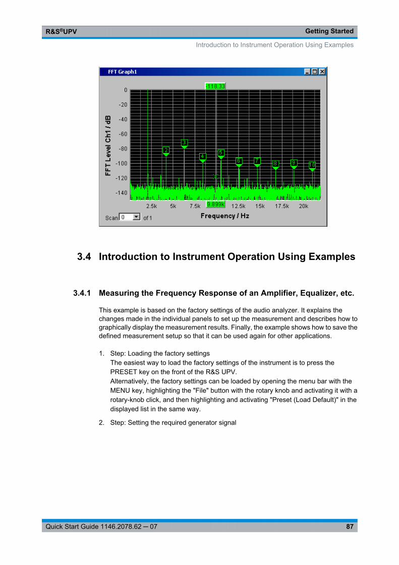
Getting StartedR&S®UPV
87Quick Start Guide 1146.2078.62 ─ 07
3.4 Introduction to Instrument Operation Using Examples
3.4.1 Measuring the Frequency Response of an Amplifier, Equalizer, etc.
This example is based on the factory settings of the audio analyzer. It explains thechanges made in the individual panels to set up the measurement and describes how tographically display the measurement results. Finally, the example shows how to save thedefined measurement setup so that it can be used again for other applications.
1. Step: Loading the factory settingsThe easiest way to load the factory settings of the instrument is to press thePRESET key on the front of the R&S UPV.Alternatively, the factory settings can be loaded by opening the menu bar with theMENU key, highlighting the "File" button with the rotary knob and activating it with arotary-knob click, and then highlighting and activating "Preset (Load Default)" in thedisplayed list in the same way.
2. Step: Setting the required generator signal
Introduction to Instrument Operation Using Examples
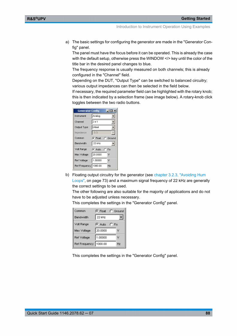
Getting StartedR&S®UPV
88Quick Start Guide 1146.2078.62 ─ 07
a) The basic settings for configuring the generator are made in the "Generator Con-fig" panel.The panel must have the focus before it can be operated. This is already the casewith the default setup, otherwise press the WINDOW </> key until the color of thetitle bar in the desired panel changes to blue.The frequency response is usually measured on both channels; this is alreadyconfigured in the "Channel" field.Depending on the DUT, "Output Type" can be switched to balanced circuitry;various output impedances can then be selected in the field below.If necessary, the required parameter field can be highlighted with the rotary knob;this is then indicated by a selection frame (see image below). A rotary-knob clicktoggles between the two radio buttons.
b) Floating output circuitry for the generator (see chapter 3.2.3, "Avoiding HumLoops", on page 73) and a maximum signal frequency of 22 kHz are generallythe correct settings to be used.The other following are also suitable for the majority of applications and do nothave to be adjusted unless necessary.This completes the settings in the "Generator Config" panel.
This completes the settings in the "Generator Config" panel.
Introduction to Instrument Operation Using Examples
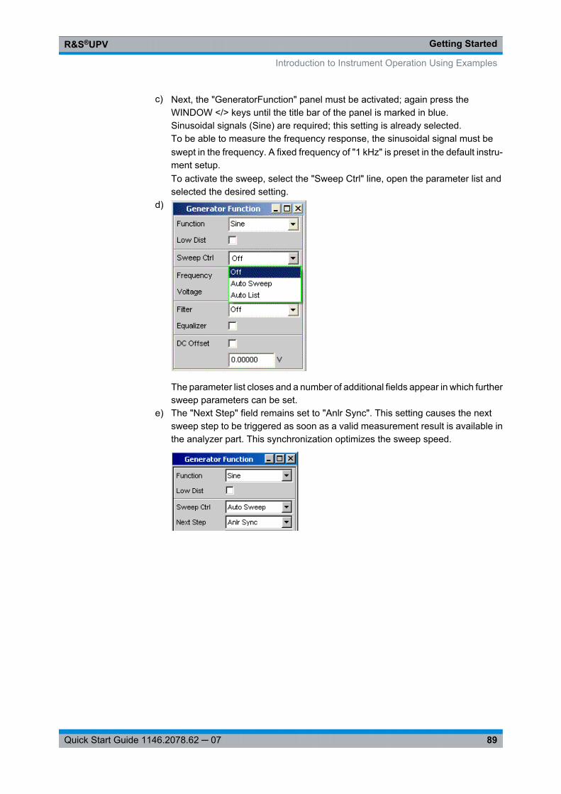
Getting StartedR&S®UPV
89Quick Start Guide 1146.2078.62 ─ 07
c) Next, the "GeneratorFunction" panel must be activated; again press theWINDOW </> keys until the title bar of the panel is marked in blue.Sinusoidal signals (Sine) are required; this setting is already selected.To be able to measure the frequency response, the sinusoidal signal must beswept in the frequency. A fixed frequency of "1 kHz" is preset in the default instru-ment setup.To activate the sweep, select the "Sweep Ctrl" line, open the parameter list andselected the desired setting.
d)
The parameter list closes and a number of additional fields appear in which furthersweep parameters can be set.
e) The "Next Step" field remains set to "Anlr Sync". This setting causes the nextsweep step to be triggered as soon as a valid measurement result is available inthe analyzer part. This synchronization optimizes the sweep speed.
Introduction to Instrument Operation Using Examples
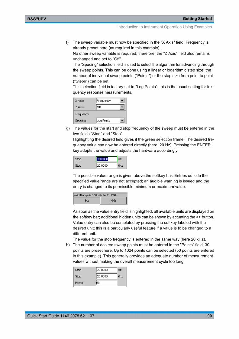
Getting StartedR&S®UPV
90Quick Start Guide 1146.2078.62 ─ 07
f) The sweep variable must now be specified in the "X Axis" field. Frequency isalready preset here (as required in this example).No other sweep variable is required; therefore, the "Z Axis" field also remainsunchanged and set to "Off".The "Spacing" selection field is used to select the algorithm for advancing throughthe sweep points. This can be done using a linear or logarithmic step size; thenumber of individual sweep points ("Points") or the step size from point to point("Steps") can be set.This selection field is factory-set to "Log Points"; this is the usual setting for fre-quency response measurements.
g) The values for the start and stop frequency of the sweep must be entered in thetwo fields "Start" and "Stop".Highlighting the desired field gives it the green selection frame. The desired fre-quency value can now be entered directly (here: 20 Hz). Pressing the ENTERkey adopts the value and adjusts the hardware accordingly.
The possible value range is given above the softkey bar. Entries outside thespecified value range are not accepted; an audible warning is issued and theentry is changed to its permissible minimum or maximum value.
As soon as the value entry field is highlighted, all available units are displayed onthe softkey bar; additional hidden units can be shown by actuating the >> button.Value entry can also be completed by pressing the softkey labeled with thedesired unit; this is a particularly useful feature if a value is to be changed to adifferent unit.The value for the stop frequency is entered in the same way (here 20 kHz).
h) The number of desired sweep points must be entered in the "Points" field, 30points are preset here. Up to 1024 points can be selected (50 points are enteredin this example). This generally provides an adequate number of measurementvalues without making the overall measurement cycle too long.
Introduction to Instrument Operation Using Examples
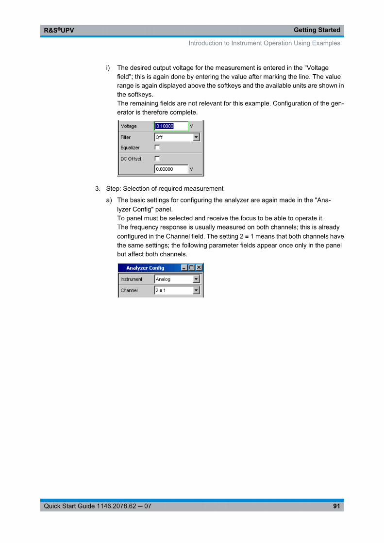
Getting StartedR&S®UPV
91Quick Start Guide 1146.2078.62 ─ 07
i) The desired output voltage for the measurement is entered in the "Voltagefield"; this is again done by entering the value after marking the line. The valuerange is again displayed above the softkeys and the available units are shown inthe softkeys.The remaining fields are not relevant for this example. Configuration of the gen-erator is therefore complete.
3. Step: Selection of required measurement
a) The basic settings for configuring the analyzer are again made in the "Ana-lyzer Config" panel.To panel must be selected and receive the focus to be able to operate it.The frequency response is usually measured on both channels; this is alreadyconfigured in the Channel field. The setting 2 ≡ 1 means that both channels havethe same settings; the following parameter fields appear once only in the panelbut affect both channels.
Introduction to Instrument Operation Using Examples
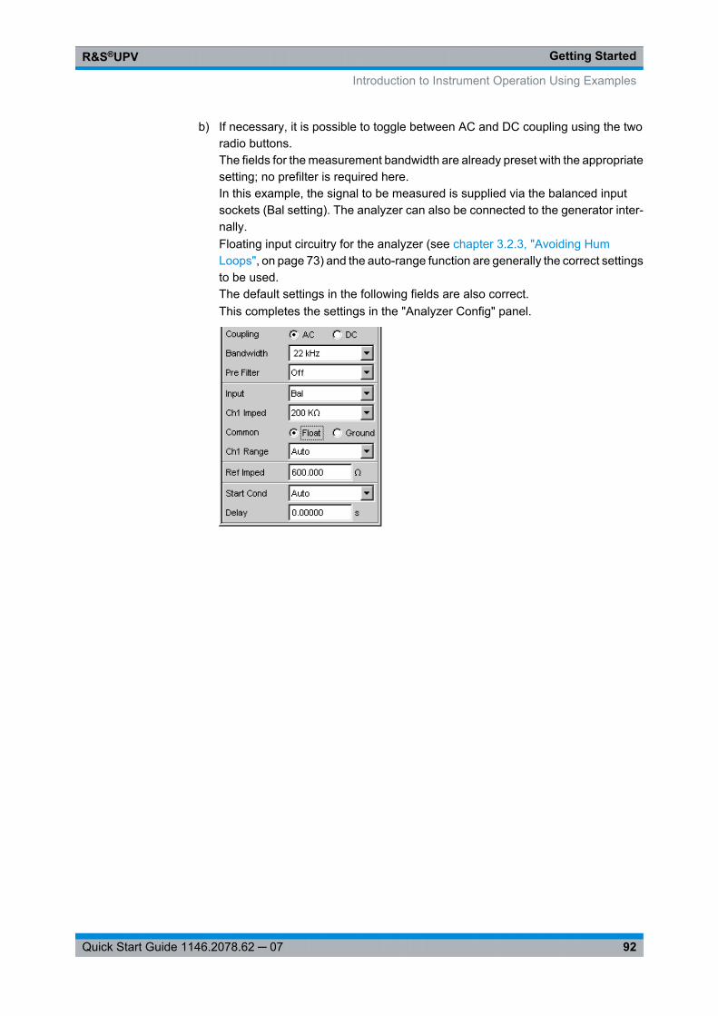
Getting StartedR&S®UPV
92Quick Start Guide 1146.2078.62 ─ 07
b) If necessary, it is possible to toggle between AC and DC coupling using the tworadio buttons.The fields for the measurement bandwidth are already preset with the appropriatesetting; no prefilter is required here.In this example, the signal to be measured is supplied via the balanced inputsockets (Bal setting). The analyzer can also be connected to the generator inter-nally.Floating input circuitry for the analyzer (see chapter 3.2.3, "Avoiding HumLoops", on page 73) and the auto-range function are generally the correct settingsto be used.The default settings in the following fields are also correct.This completes the settings in the "Analyzer Config" panel.
Introduction to Instrument Operation Using Examples
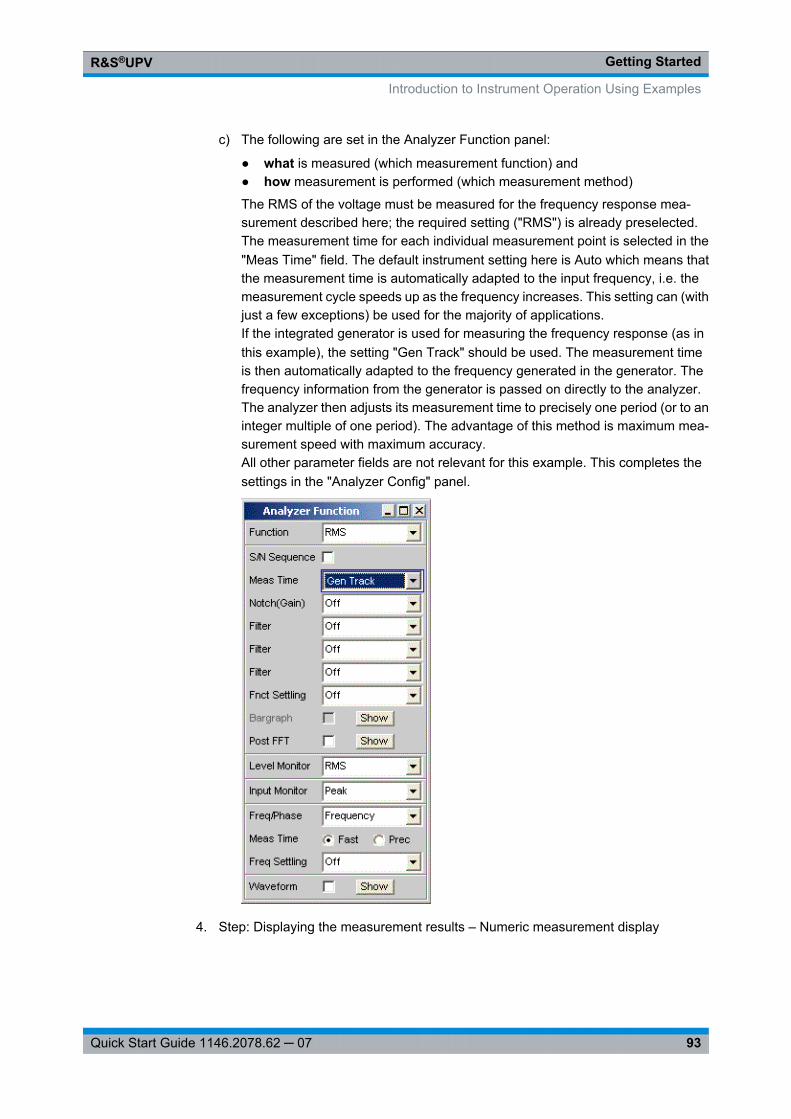
Getting StartedR&S®UPV
93Quick Start Guide 1146.2078.62 ─ 07
c) The following are set in the Analyzer Function panel:
● what is measured (which measurement function) and● how measurement is performed (which measurement method)
The RMS of the voltage must be measured for the frequency response mea-surement described here; the required setting ("RMS") is already preselected.The measurement time for each individual measurement point is selected in the"Meas Time" field. The default instrument setting here is Auto which means thatthe measurement time is automatically adapted to the input frequency, i.e. themeasurement cycle speeds up as the frequency increases. This setting can (withjust a few exceptions) be used for the majority of applications.If the integrated generator is used for measuring the frequency response (as inthis example), the setting "Gen Track" should be used. The measurement timeis then automatically adapted to the frequency generated in the generator. Thefrequency information from the generator is passed on directly to the analyzer.The analyzer then adjusts its measurement time to precisely one period (or to aninteger multiple of one period). The advantage of this method is maximum mea-surement speed with maximum accuracy.All other parameter fields are not relevant for this example. This completes thesettings in the "Analyzer Config" panel.
4. Step: Displaying the measurement results – Numeric measurement display
Introduction to Instrument Operation Using Examples
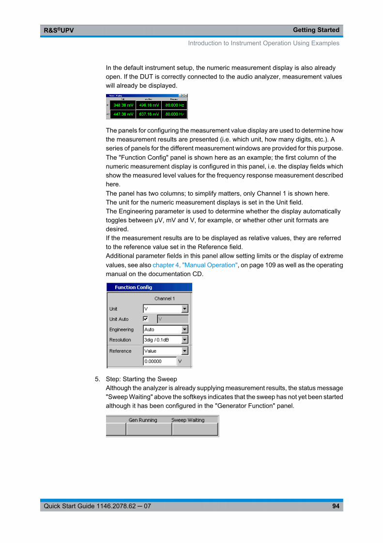
Getting StartedR&S®UPV
94Quick Start Guide 1146.2078.62 ─ 07
In the default instrument setup, the numeric measurement display is also alreadyopen. If the DUT is correctly connected to the audio analyzer, measurement valueswill already be displayed.
The panels for configuring the measurement value display are used to determine howthe measurement results are presented (i.e. which unit, how many digits, etc.). Aseries of panels for the different measurement windows are provided for this purpose.The "Function Config" panel is shown here as an example; the first column of thenumeric measurement display is configured in this panel, i.e. the display fields whichshow the measured level values for the frequency response measurement describedhere.The panel has two columns; to simplify matters, only Channel 1 is shown here.The unit for the numeric measurement displays is set in the Unit field.The Engineering parameter is used to determine whether the display automaticallytoggles between µV, mV and V, for example, or whether other unit formats aredesired.If the measurement results are to be displayed as relative values, they are referredto the reference value set in the Reference field.Additional parameter fields in this panel allow setting limits or the display of extremevalues, see also chapter 4, "Manual Operation", on page 109 as well as the operatingmanual on the documentation CD.
5. Step: Starting the SweepAlthough the analyzer is already supplying measurement results, the status message"Sweep Waiting" above the softkeys indicates that the sweep has not yet been startedalthough it has been configured in the "Generator Function" panel.
Introduction to Instrument Operation Using Examples
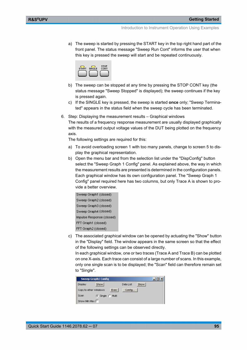
Getting StartedR&S®UPV
95Quick Start Guide 1146.2078.62 ─ 07
a) The sweep is started by pressing the START key in the top right hand part of thefront panel. The status message "Sweep Run Cont" informs the user that whenthis key is pressed the sweep will start and be repeated continuously.
b) The sweep can be stopped at any time by pressing the STOP CONT key (thestatus message "Sweep Stopped" is displayed); the sweep continues if the keyis pressed again.
c) If the SINGLE key is pressed, the sweep is started once only; "Sweep Termina-ted" appears in the status field when the sweep cycle has been terminated.
6. Step: Displaying the measurement results – Graphical windowsThe results of a frequency response measurement are usually displayed graphicallywith the measured output voltage values of the DUT being plotted on the frequencyaxis.The following settings are required for this:
a) To avoid overloading screen 1 with too many panels, change to screen 5 to dis-play the graphical representation.
b) Open the menu bar and from the selection list under the "DispConfig" buttonselect the "Sweep Graph 1 Config" panel. As explained above, the way in whichthe measurement results are presented is determined in the configuration panels.Each graphical window has its own configuration panel. The "Sweep Graph 1Config" panel required here has two columns, but only Trace A is shown to pro-vide a better overview.
c) The associated graphical window can be opened by actuating the "Show" buttonin the "Display" field. The window appears in the same screen so that the effectof the following settings can be observed directly.In each graphical window, one or two traces (Trace A and Trace B) can be plottedon one X-axis. Each trace can consist of a large number of scans. In this example,only one single scan is to be displayed; the "Scan" field can therefore remain setto "Single".
Introduction to Instrument Operation Using Examples
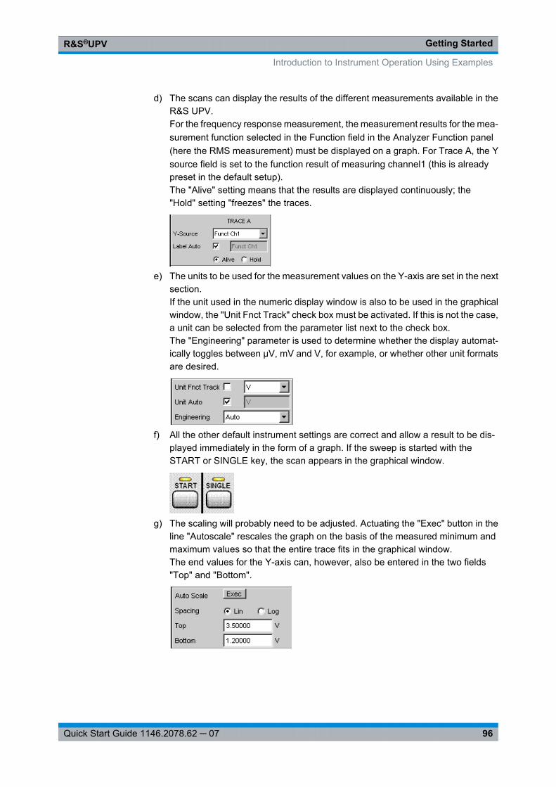
Getting StartedR&S®UPV
96Quick Start Guide 1146.2078.62 ─ 07
d) The scans can display the results of the different measurements available in theR&S UPV.For the frequency response measurement, the measurement results for the mea-surement function selected in the Function field in the Analyzer Function panel(here the RMS measurement) must be displayed on a graph. For Trace A, the Ysource field is set to the function result of measuring channel1 (this is alreadypreset in the default setup).The "Alive" setting means that the results are displayed continuously; the"Hold" setting "freezes" the traces.
e) The units to be used for the measurement values on the Y-axis are set in the nextsection.If the unit used in the numeric display window is also to be used in the graphicalwindow, the "Unit Fnct Track" check box must be activated. If this is not the case,a unit can be selected from the parameter list next to the check box.The "Engineering" parameter is used to determine whether the display automat-ically toggles between µV, mV and V, for example, or whether other unit formatsare desired.
f) All the other default instrument settings are correct and allow a result to be dis-played immediately in the form of a graph. If the sweep is started with theSTART or SINGLE key, the scan appears in the graphical window.
g) The scaling will probably need to be adjusted. Actuating the "Exec" button in theline "Autoscale" rescales the graph on the basis of the measured minimum andmaximum values so that the entire trace fits in the graphical window.The end values for the Y-axis can, however, also be entered in the two fields"Top" and "Bottom".
Introduction to Instrument Operation Using Examples
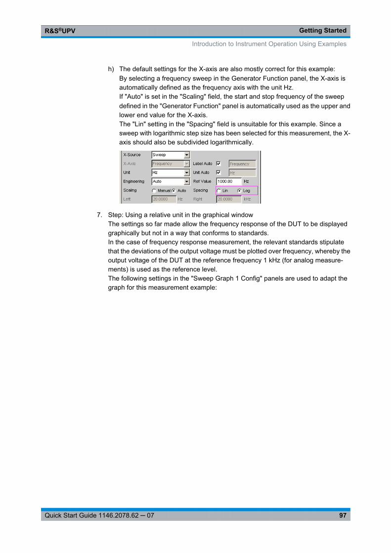
Getting StartedR&S®UPV
97Quick Start Guide 1146.2078.62 ─ 07
h) The default settings for the X-axis are also mostly correct for this example:By selecting a frequency sweep in the Generator Function panel, the X-axis isautomatically defined as the frequency axis with the unit Hz.If "Auto" is set in the "Scaling" field, the start and stop frequency of the sweepdefined in the "Generator Function" panel is automatically used as the upper andlower end value for the X-axis.The "Lin" setting in the "Spacing" field is unsuitable for this example. Since asweep with logarithmic step size has been selected for this measurement, the X-axis should also be subdivided logarithmically.
7. Step: Using a relative unit in the graphical windowThe settings so far made allow the frequency response of the DUT to be displayedgraphically but not in a way that conforms to standards.In the case of frequency response measurement, the relevant standards stipulatethat the deviations of the output voltage must be plotted over frequency, whereby theoutput voltage of the DUT at the reference frequency 1 kHz (for analog measure-ments) is used as the reference level.The following settings in the "Sweep Graph 1 Config" panels are used to adapt thegraph for this measurement example:
Introduction to Instrument Operation Using Examples
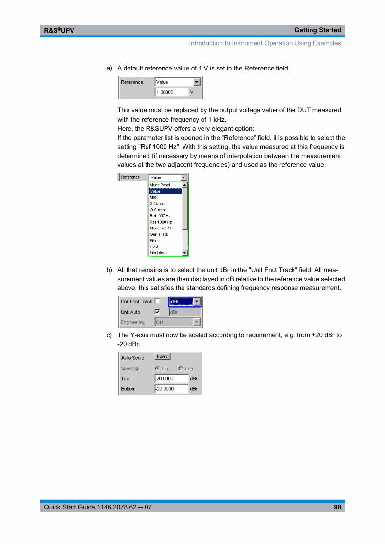
Getting StartedR&S®UPV
98Quick Start Guide 1146.2078.62 ─ 07
a) A default reference value of 1 V is set in the Reference field.
This value must be replaced by the output voltage value of the DUT measuredwith the reference frequency of 1 kHz.Here, the R&SUPV offers a very elegant option:If the parameter list is opened in the "Reference" field, it is possible to select thesetting "Ref 1000 Hz". With this setting, the value measured at this frequency isdetermined (if necessary by means of interpolation between the measurementvalues at the two adjacent frequencies) and used as the reference value.
b) All that remains is to select the unit dBr in the "Unit Fnct Track" field. All mea-surement values are then displayed in dB relative to the reference value selectedabove; this satisfies the standards defining frequency response measurement.
c) The Y-axis must now be scaled according to requirement, e.g. from +20 dBr to-20 dBr.
Introduction to Instrument Operation Using Examples
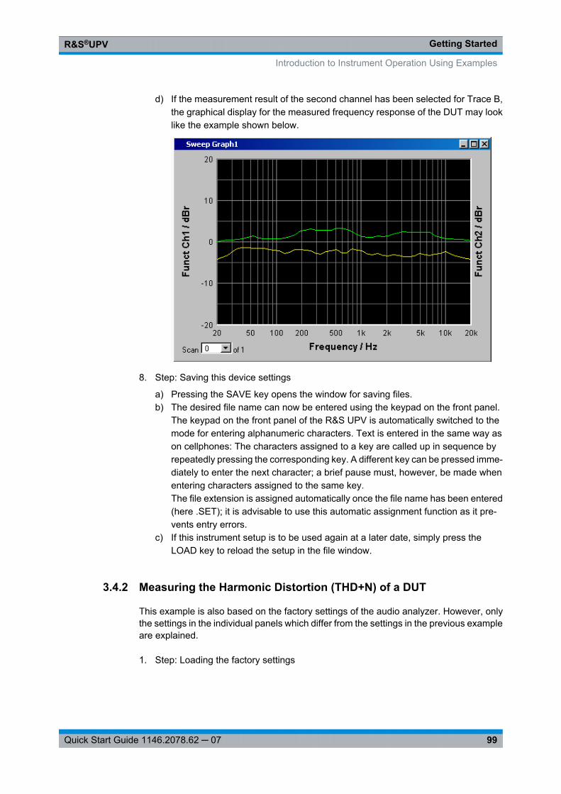
Getting StartedR&S®UPV
99Quick Start Guide 1146.2078.62 ─ 07
d) If the measurement result of the second channel has been selected for Trace B,the graphical display for the measured frequency response of the DUT may looklike the example shown below.
8. Step: Saving this device settings
a) Pressing the SAVE key opens the window for saving files.b) The desired file name can now be entered using the keypad on the front panel.
The keypad on the front panel of the R&S UPV is automatically switched to themode for entering alphanumeric characters. Text is entered in the same way ason cellphones: The characters assigned to a key are called up in sequence byrepeatedly pressing the corresponding key. A different key can be pressed imme-diately to enter the next character; a brief pause must, however, be made whenentering characters assigned to the same key.The file extension is assigned automatically once the file name has been entered(here .SET); it is advisable to use this automatic assignment function as it pre-vents entry errors.
c) If this instrument setup is to be used again at a later date, simply press theLOAD key to reload the setup in the file window.
3.4.2 Measuring the Harmonic Distortion (THD+N) of a DUT
This example is also based on the factory settings of the audio analyzer. However, onlythe settings in the individual panels which differ from the settings in the previous exampleare explained.
1. Step: Loading the factory settings
Introduction to Instrument Operation Using Examples
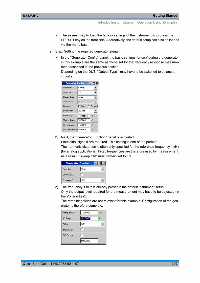
Getting StartedR&S®UPV
100Quick Start Guide 1146.2078.62 ─ 07
a) The easiest way to load the factory settings of the instrument is to press thePRESET key on the front side. Alternatively, the default setup can also be loadedvia the menu bar.
2. Step: Setting the required generator signal
a) In the "Generator Config" panel, the basic settings for configuring the generatorin this example are the same as those set for the frequency response measure-ment described in the previous section.Depending on the DUT, "Output Type " may have to be switched to balancedcircuitry.
b) Next, the "Generator Function" panel is activated.Sinusoidal signals are required. This setting is one of the presets.The harmonic distortion is often only specified for the reference frequency 1 kHz(for analog applications). Fixed frequencies are therefore used for measurement;as a result, "Sweep Ctrl" must remain set to Off.
c) The frequency 1 kHz is already preset in the default instrument setup.Only the output level required for the measurement may have to be adjusted (inthe Voltage field).The remaining fields are not relevant for this example. Configuration of the gen-erator is therefore complete.
Introduction to Instrument Operation Using Examples
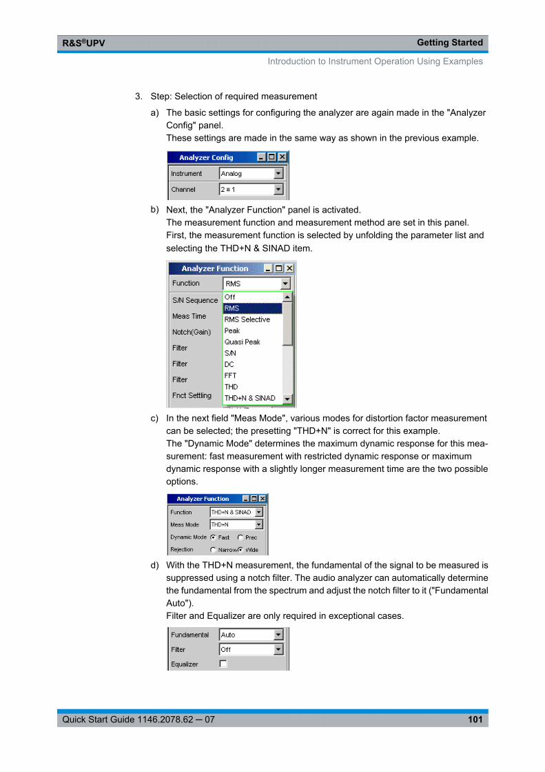
Getting StartedR&S®UPV
101Quick Start Guide 1146.2078.62 ─ 07
3. Step: Selection of required measurement
a) The basic settings for configuring the analyzer are again made in the "AnalyzerConfig" panel.These settings are made in the same way as shown in the previous example.
b) Next, the "Analyzer Function" panel is activated.The measurement function and measurement method are set in this panel.First, the measurement function is selected by unfolding the parameter list andselecting the THD+N & SINAD item.
c) In the next field "Meas Mode", various modes for distortion factor measurementcan be selected; the presetting "THD+N" is correct for this example.The "Dynamic Mode" determines the maximum dynamic response for this mea-surement: fast measurement with restricted dynamic response or maximumdynamic response with a slightly longer measurement time are the two possibleoptions.
d) With the THD+N measurement, the fundamental of the signal to be measured issuppressed using a notch filter. The audio analyzer can automatically determinethe fundamental from the spectrum and adjust the notch filter to it ("FundamentalAuto").Filter and Equalizer are only required in exceptional cases.
Introduction to Instrument Operation Using Examples
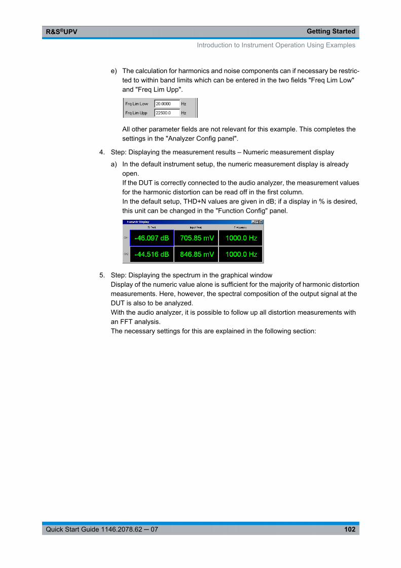
Getting StartedR&S®UPV
102Quick Start Guide 1146.2078.62 ─ 07
e) The calculation for harmonics and noise components can if necessary be restric-ted to within band limits which can be entered in the two fields "Freq Lim Low"and "Freq Lim Upp".
All other parameter fields are not relevant for this example. This completes thesettings in the "Analyzer Config panel".
4. Step: Displaying the measurement results – Numeric measurement display
a) In the default instrument setup, the numeric measurement display is alreadyopen.If the DUT is correctly connected to the audio analyzer, the measurement valuesfor the harmonic distortion can be read off in the first column.In the default setup, THD+N values are given in dB; if a display in % is desired,this unit can be changed in the "Function Config" panel.
5. Step: Displaying the spectrum in the graphical windowDisplay of the numeric value alone is sufficient for the majority of harmonic distortionmeasurements. Here, however, the spectral composition of the output signal at theDUT is also to be analyzed.With the audio analyzer, it is possible to follow up all distortion measurements withan FFT analysis.The necessary settings for this are explained in the following section:
Introduction to Instrument Operation Using Examples
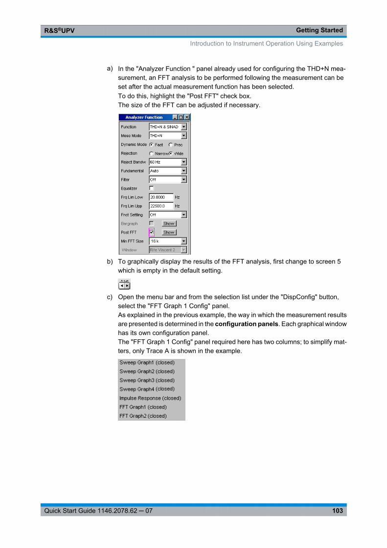
Getting StartedR&S®UPV
103Quick Start Guide 1146.2078.62 ─ 07
a) In the "Analyzer Function " panel already used for configuring the THD+N mea-surement, an FFT analysis to be performed following the measurement can beset after the actual measurement function has been selected.To do this, highlight the "Post FFT" check box.The size of the FFT can be adjusted if necessary.
b) To graphically display the results of the FFT analysis, first change to screen 5which is empty in the default setting.
c) Open the menu bar and from the selection list under the "DispConfig" button,select the "FFT Graph 1 Config" panel.As explained in the previous example, the way in which the measurement resultsare presented is determined in the configuration panels. Each graphical windowhas its own configuration panel.The "FFT Graph 1 Config" panel required here has two columns; to simplify mat-ters, only Trace A is shown in the example.
Introduction to Instrument Operation Using Examples
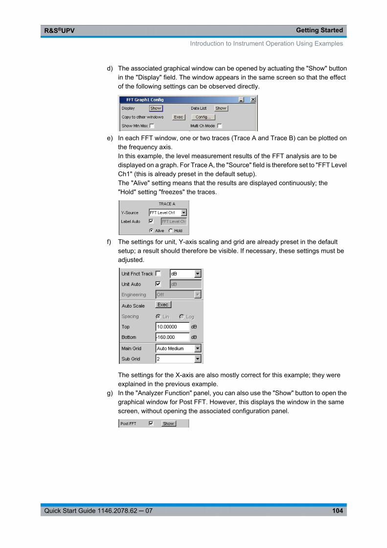
Getting StartedR&S®UPV
104Quick Start Guide 1146.2078.62 ─ 07
d) The associated graphical window can be opened by actuating the "Show" buttonin the "Display" field. The window appears in the same screen so that the effectof the following settings can be observed directly.
e) In each FFT window, one or two traces (Trace A and Trace B) can be plotted onthe frequency axis.In this example, the level measurement results of the FFT analysis are to bedisplayed on a graph. For Trace A, the "Source" field is therefore set to "FFT LevelCh1" (this is already preset in the default setup).The "Alive" setting means that the results are displayed continuously; the"Hold" setting "freezes" the traces.
f) The settings for unit, Y-axis scaling and grid are already preset in the defaultsetup; a result should therefore be visible. If necessary, these settings must beadjusted.
The settings for the X-axis are also mostly correct for this example; they wereexplained in the previous example.
g) In the "Analyzer Function" panel, you can also use the "Show" button to open thegraphical window for Post FFT. However, this displays the window in the samescreen, without opening the associated configuration panel.
Introduction to Instrument Operation Using Examples
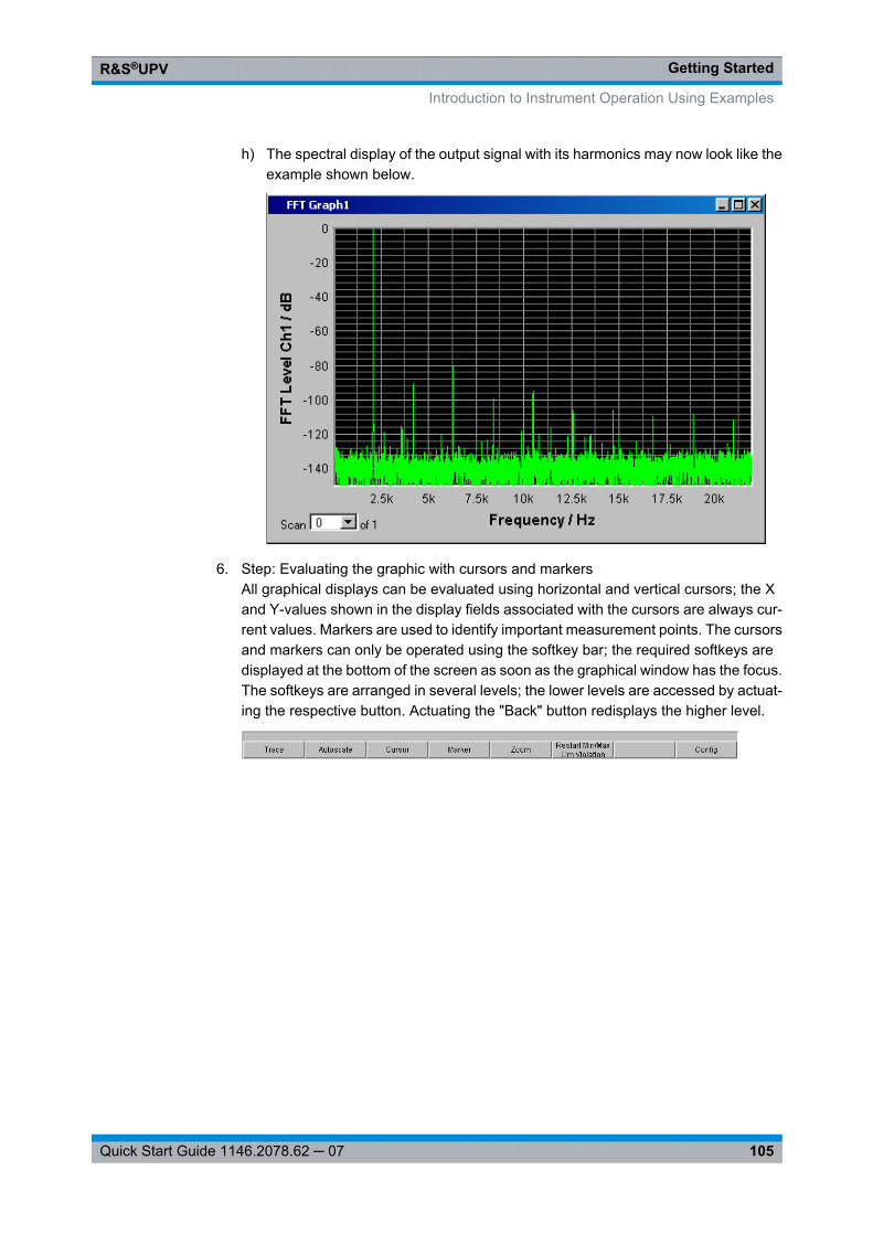
Getting StartedR&S®UPV
105Quick Start Guide 1146.2078.62 ─ 07
h) The spectral display of the output signal with its harmonics may now look like theexample shown below.
6. Step: Evaluating the graphic with cursors and markersAll graphical displays can be evaluated using horizontal and vertical cursors; the Xand Y-values shown in the display fields associated with the cursors are always cur-rent values. Markers are used to identify important measurement points. The cursorsand markers can only be operated using the softkey bar; the required softkeys aredisplayed at the bottom of the screen as soon as the graphical window has the focus.The softkeys are arranged in several levels; the lower levels are accessed by actuat-ing the respective button. Actuating the "Back" button redisplays the higher level.
Introduction to Instrument Operation Using Examples
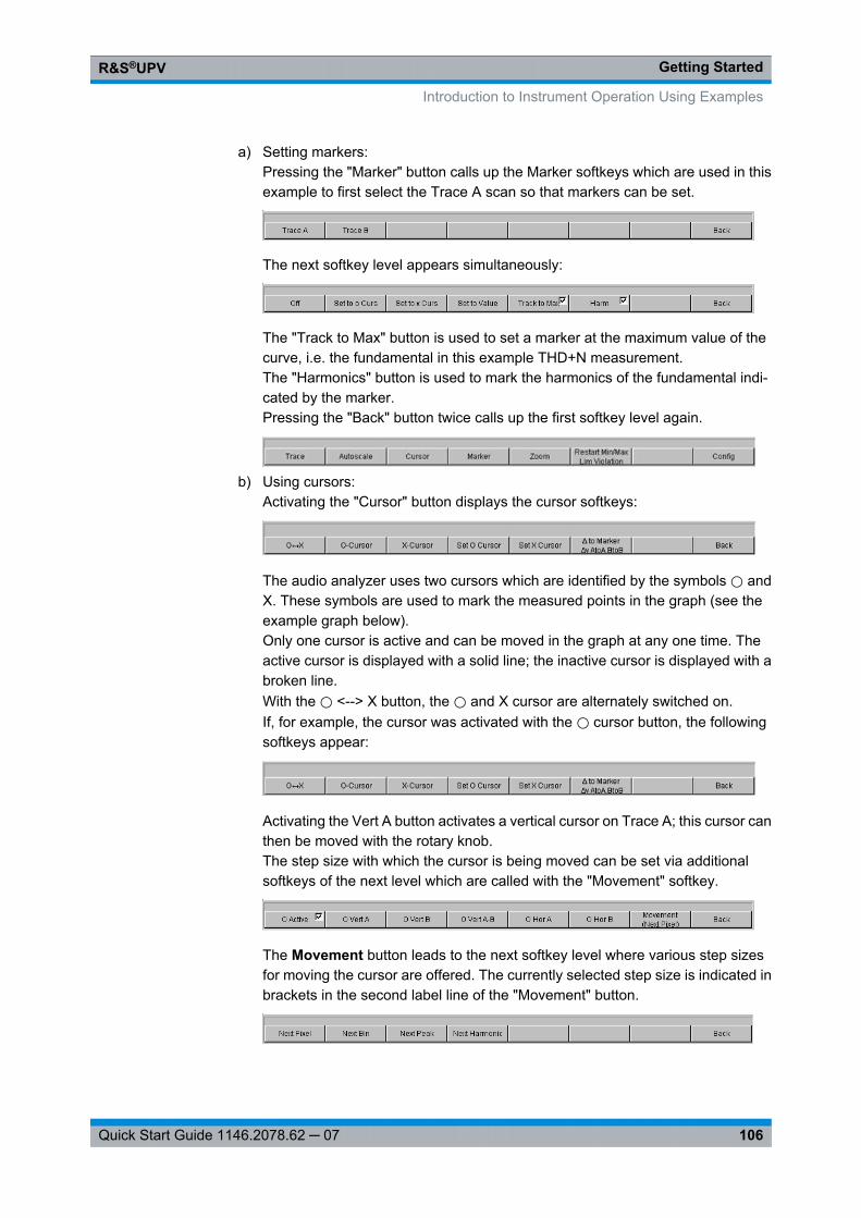
Getting StartedR&S®UPV
106Quick Start Guide 1146.2078.62 ─ 07
a) Setting markers:Pressing the "Marker" button calls up the Marker softkeys which are used in thisexample to first select the Trace A scan so that markers can be set.
The next softkey level appears simultaneously:
The "Track to Max" button is used to set a marker at the maximum value of thecurve, i.e. the fundamental in this example THD+N measurement.The "Harmonics" button is used to mark the harmonics of the fundamental indi-cated by the marker.Pressing the "Back" button twice calls up the first softkey level again.
b) Using cursors:Activating the "Cursor" button displays the cursor softkeys:
The audio analyzer uses two cursors which are identified by the symbols ⃝ andX. These symbols are used to mark the measured points in the graph (see theexample graph below).Only one cursor is active and can be moved in the graph at any one time. Theactive cursor is displayed with a solid line; the inactive cursor is displayed with abroken line.With the ⃝ <--> X button, the ⃝ and X cursor are alternately switched on.If, for example, the cursor was activated with the ⃝ cursor button, the followingsoftkeys appear:
Activating the Vert A button activates a vertical cursor on Trace A; this cursor canthen be moved with the rotary knob.The step size with which the cursor is being moved can be set via additionalsoftkeys of the next level which are called with the "Movement" softkey.
The Movement button leads to the next softkey level where various step sizesfor moving the cursor are offered. The currently selected step size is indicated inbrackets in the second label line of the "Movement" button.
Introduction to Instrument Operation Using Examples
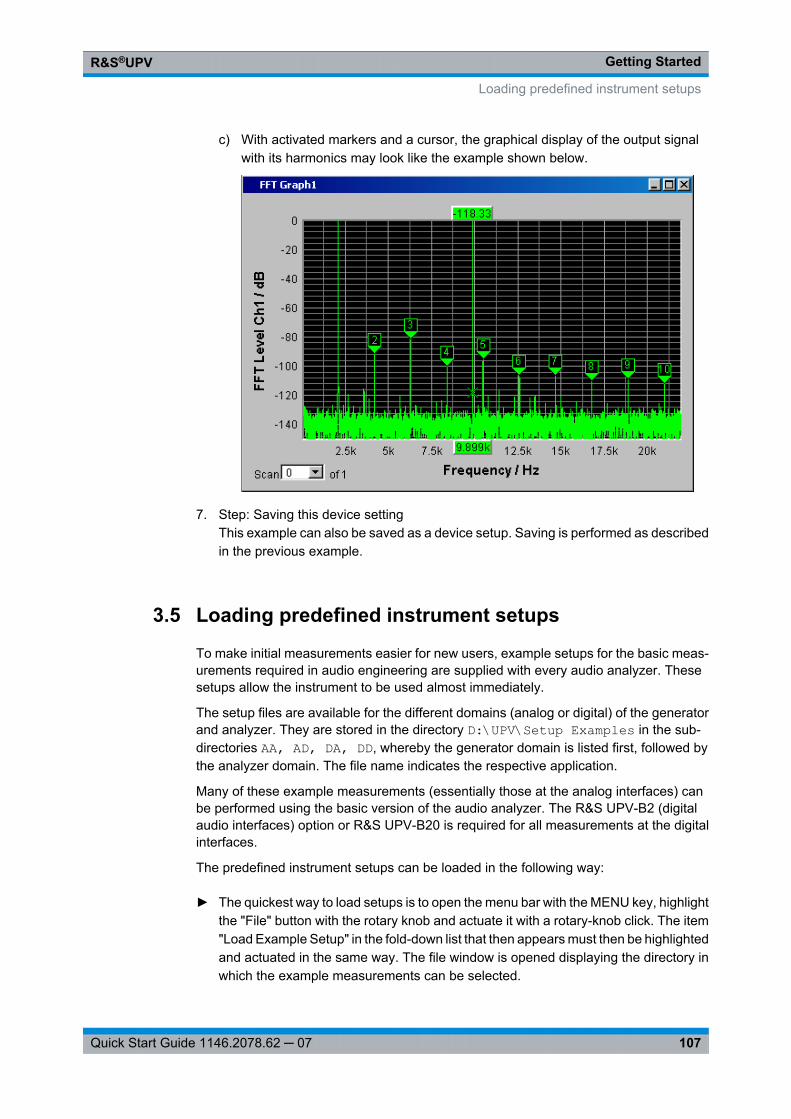
Getting StartedR&S®UPV
107Quick Start Guide 1146.2078.62 ─ 07
c) With activated markers and a cursor, the graphical display of the output signalwith its harmonics may look like the example shown below.
7. Step: Saving this device settingThis example can also be saved as a device setup. Saving is performed as describedin the previous example.
3.5 Loading predefined instrument setups
To make initial measurements easier for new users, example setups for the basic meas-urements required in audio engineering are supplied with every audio analyzer. Thesesetups allow the instrument to be used almost immediately.
The setup files are available for the different domains (analog or digital) of the generatorand analyzer. They are stored in the directory D:\UPV\Setup Examples in the sub-directories AA, AD, DA, DD, whereby the generator domain is listed first, followed bythe analyzer domain. The file name indicates the respective application.
Many of these example measurements (essentially those at the analog interfaces) canbe performed using the basic version of the audio analyzer. The R&S UPV-B2 (digitalaudio interfaces) option or R&S UPV-B20 is required for all measurements at the digitalinterfaces.
The predefined instrument setups can be loaded in the following way:
► The quickest way to load setups is to open the menu bar with the MENU key, highlightthe "File" button with the rotary knob and actuate it with a rotary-knob click. The item"Load Example Setup" in the fold-down list that then appears must then be highlightedand actuated in the same way. The file window is opened displaying the directory inwhich the example measurements can be selected.
Loading predefined instrument setups
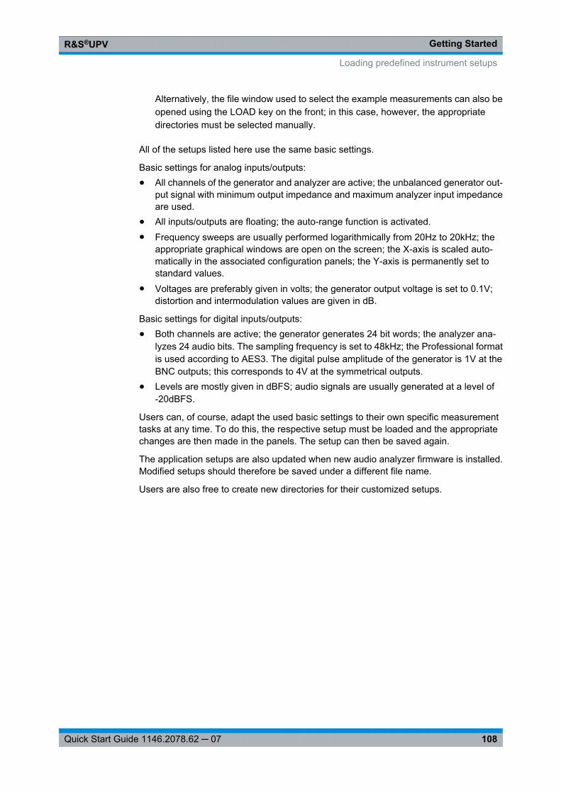
Getting StartedR&S®UPV
108Quick Start Guide 1146.2078.62 ─ 07
Alternatively, the file window used to select the example measurements can also beopened using the LOAD key on the front; in this case, however, the appropriatedirectories must be selected manually.
All of the setups listed here use the same basic settings.
Basic settings for analog inputs/outputs:● All channels of the generator and analyzer are active; the unbalanced generator out-
put signal with minimum output impedance and maximum analyzer input impedanceare used.
● All inputs/outputs are floating; the auto-range function is activated.● Frequency sweeps are usually performed logarithmically from 20Hz to 20kHz; the
appropriate graphical windows are open on the screen; the X-axis is scaled auto-matically in the associated configuration panels; the Y-axis is permanently set tostandard values.
● Voltages are preferably given in volts; the generator output voltage is set to 0.1V;distortion and intermodulation values are given in dB.
Basic settings for digital inputs/outputs:● Both channels are active; the generator generates 24 bit words; the analyzer ana-
lyzes 24 audio bits. The sampling frequency is set to 48kHz; the Professional formatis used according to AES3. The digital pulse amplitude of the generator is 1V at theBNC outputs; this corresponds to 4V at the symmetrical outputs.
● Levels are mostly given in dBFS; audio signals are usually generated at a level of-20dBFS.
Users can, of course, adapt the used basic settings to their own specific measurementtasks at any time. To do this, the respective setup must be loaded and the appropriatechanges are then made in the panels. The setup can then be saved again.
The application setups are also updated when new audio analyzer firmware is installed.Modified setups should therefore be saved under a different file name.
Users are also free to create new directories for their customized setups.
Loading predefined instrument setups
Manual OperationR&S®UPV
109Quick Start Guide 1146.2078.62 ─ 07
4 Manual Operation
4.1 Introduction - Manual Operation
The R&S UPV audio analyzer is available in two models. The R&S UPV standard modeland the R&S UPV66 which is specially designed for use in systems and has no display,not front panel controls and no CD/DVD drive. Apart from the omission of front-paneloperation, the R&S UPV66 model has largely the same functions as the standard model.This manual therefore describes both instruments in parallel without referencing the R&SUPV66 model in particular, and any differences are indicated at the appropriate points inthe text.
The R&S UPV audio analyzer uses the Windows® XP operating system. The instrumentis therefore operated in largely the same way as other Windows® applications. All panelsand display windows have the standard Windows® format and are operated in the sameway. The rotary knob, keys and softkeys, or alternatively an external keyboard and/ormouse, allow direct and convenient access to entries and settings. The clearly organizeddisplay shows the current state of the audio analyzer.
The R&S UPV model can be fully operated using the control elements on the front panel;additional peripherals such as a mouse and keyboard are not essential requirements.They can, however, be connected so that the user is free to decide how he would like tooperate the R&S UPV. Mixed operation is also possible.
If the R&S UPV66 model is to be operated manually, you need to connect an externalmonitor, a mouse, and a PC keyboard. The section "Overview of Keys" at the end of thischapter provides the keys and shortcuts on a PC keyboard that correspond to the front-panel keys available with the R&S UPV model. For further information on operation bymeans of mouse and keyboard, refer to the sections "Operation Using the Mouse" and"Operation Using an External PC Keyboard" in this chapter.
The use of the toolbar simplifies the operation of both models when using the mouse.See chapter 4.9, "Settings in the Menu Bar", on page 175.
Numerous online help functions assist the user in making settings.
After being switched on, the instrument is in the same state as it was before it wasswitched off. This applies to all setting parameters of the R&S UPV, including those notcurrently displayed on the screen.
The following chapter describes the manual operation of the R&S UPV audio analyzer.This includes a description of the screen displays, how to operate the panels and how toset parameters. Each of the setting descriptions is accompanied by a table explaininghow the different functions are performed via the front panel and using an external PCkeyboard or mouse.
An overview of the keys, panels and display windows can be found at the end of thischapter.
Introduction - Manual Operation
Manual OperationR&S®UPV
110Quick Start Guide 1146.2078.62 ─ 07
The functions and the remote control of the R&S UPV audio analyzer are described indetail in the operating manual which is located on the supplied documentation CD. Thequick start guide features an explanation of the general operating concept and a briefintroduction that contains step-by-step configurations for initial measurements (see chapter 3, "Getting Started", on page 71).
4.2 Functional Division of the Audio Analyzer
4.2.1 Instrument concept
The audio analyzer combines the following components in a single housing:● Generators with analog and – with the R&S UPV-B2 option (digital audio interfaces)
(or R&S UPV-B20) – also digital audio interfaces for generating the multiple test sig-nals,
● Analyzers with analog and – with the R&SUPV-B2 option (or R&SUPV-B20) – alsodigital audio interfaces for extensive measurement options and
● a computer (PC) with the Windows XP® operating system for controlling and oper-ating the entire instrument and with connections for PC peripherals and LAN
4.2.2 Generators
4.2.2.1 Universal generator
The universal generator consists of signal processors and generates the various testsignals from sinusoidal tones through intermodulation test signals (two-tone signals) tonoise signals and multi-tones. Following appropriate conversion, these signal are madeavailable at the analog outputs.
With the R&S UPV-B2 option (digital audio interfaces) (or R&SUPV-B20), they can alsobe output as digital data streams in various formats at the AES/EBU or SPDIF interfacesas well as at optical interfaces.
The R&S UPV-B4x, options, which can be installed in the expansion slots at the rear ofthe instrument, provide further interfaces for outputting the test signals.
With the R&S UPV-B2 (digital audio interfaces) and -K21 (digital audio protocol) optionscan also be used to generate digital ancillary data, such as channel status data, validityand parity bits.
With the R&S UPV-B2 (digital audio interfaces) and -K22 options allow the universalgenerator to be used to generate impairment signals for applying jitter or common-modeinterferences to the DUT connected to the AES/EBU or SPDIF interfaces.
Functional Division of the Audio Analyzer
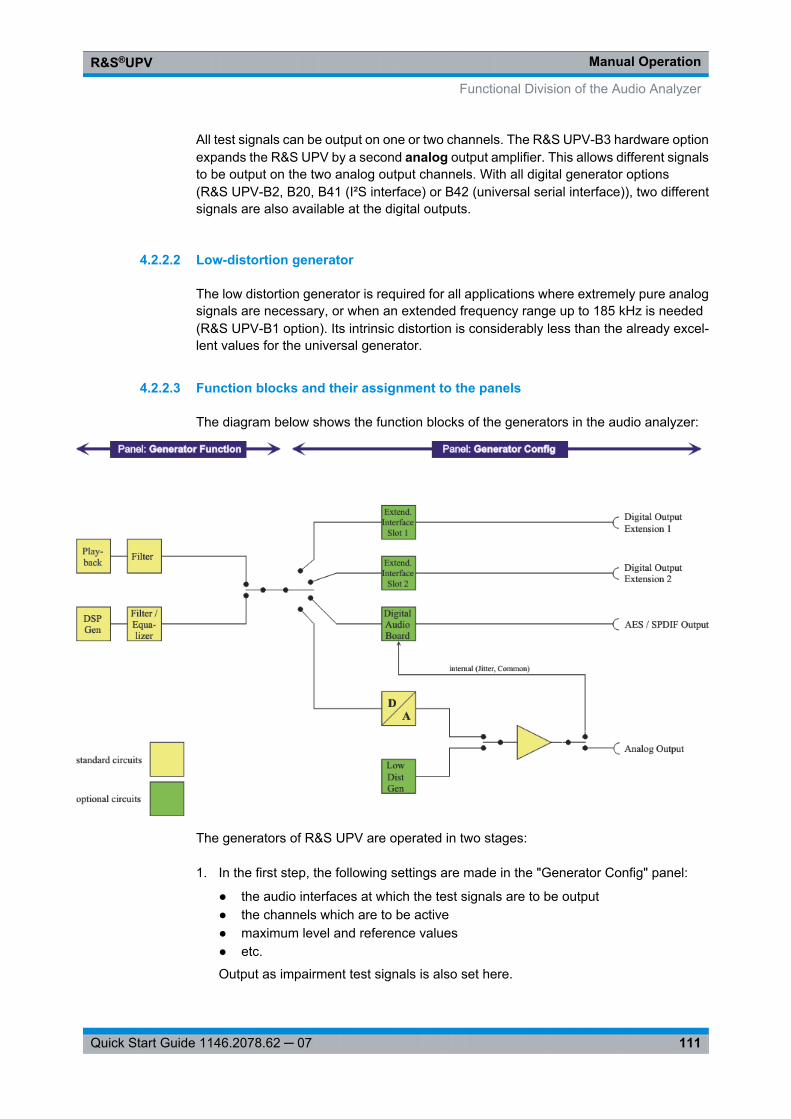
Manual OperationR&S®UPV
111Quick Start Guide 1146.2078.62 ─ 07
All test signals can be output on one or two channels. The R&S UPV-B3 hardware optionexpands the R&S UPV by a second analog output amplifier. This allows different signalsto be output on the two analog output channels. With all digital generator options(R&S UPV-B2, B20, B41 (I²S interface) or B42 (universal serial interface)), two differentsignals are also available at the digital outputs.
4.2.2.2 Low-distortion generator
The low distortion generator is required for all applications where extremely pure analogsignals are necessary, or when an extended frequency range up to 185 kHz is needed(R&S UPV-B1 option). Its intrinsic distortion is considerably less than the already excel-lent values for the universal generator.
4.2.2.3 Function blocks and their assignment to the panels
The diagram below shows the function blocks of the generators in the audio analyzer:
The generators of R&S UPV are operated in two stages:
1. In the first step, the following settings are made in the "Generator Config" panel:
● the audio interfaces at which the test signals are to be output● the channels which are to be active● maximum level and reference values● etc.
Output as impairment test signals is also set here.
Functional Division of the Audio Analyzer
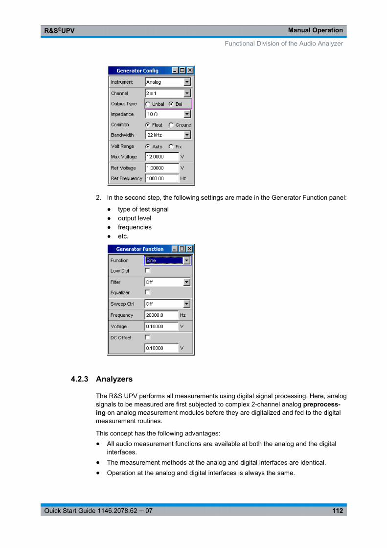
Manual OperationR&S®UPV
112Quick Start Guide 1146.2078.62 ─ 07
2. In the second step, the following settings are made in the Generator Function panel:
● type of test signal● output level● frequencies● etc.
4.2.3 Analyzers
The R&S UPV performs all measurements using digital signal processing. Here, analogsignals to be measured are first subjected to complex 2-channel analog preprocess-ing on analog measurement modules before they are digitalized and fed to the digitalmeasurement routines.
This concept has the following advantages:● All audio measurement functions are available at both the analog and the digital
interfaces.● The measurement methods at the analog and digital interfaces are identical.● Operation at the analog and digital interfaces is always the same.
Functional Division of the Audio Analyzer
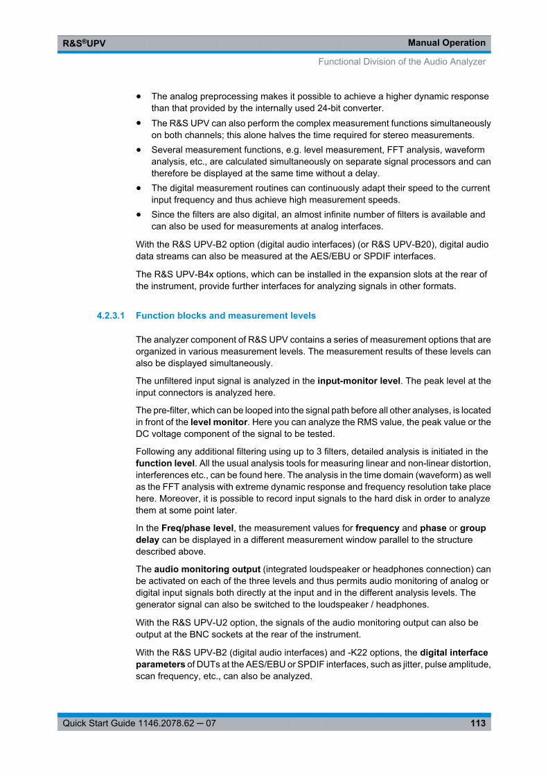
Manual OperationR&S®UPV
113Quick Start Guide 1146.2078.62 ─ 07
● The analog preprocessing makes it possible to achieve a higher dynamic responsethan that provided by the internally used 24-bit converter.
● The R&S UPV can also perform the complex measurement functions simultaneouslyon both channels; this alone halves the time required for stereo measurements.
● Several measurement functions, e.g. level measurement, FFT analysis, waveformanalysis, etc., are calculated simultaneously on separate signal processors and cantherefore be displayed at the same time without a delay.
● The digital measurement routines can continuously adapt their speed to the currentinput frequency and thus achieve high measurement speeds.
● Since the filters are also digital, an almost infinite number of filters is available andcan also be used for measurements at analog interfaces.
With the R&S UPV-B2 option (digital audio interfaces) (or R&S UPV-B20), digital audiodata streams can also be measured at the AES/EBU or SPDIF interfaces.
The R&S UPV-B4x options, which can be installed in the expansion slots at the rear ofthe instrument, provide further interfaces for analyzing signals in other formats.
4.2.3.1 Function blocks and measurement levels
The analyzer component of R&S UPV contains a series of measurement options that areorganized in various measurement levels. The measurement results of these levels canalso be displayed simultaneously.
The unfiltered input signal is analyzed in the input-monitor level. The peak level at theinput connectors is analyzed here.
The pre-filter, which can be looped into the signal path before all other analyses, is locatedin front of the level monitor. Here you can analyze the RMS value, the peak value or theDC voltage component of the signal to be tested.
Following any additional filtering using up to 3 filters, detailed analysis is initiated in thefunction level. All the usual analysis tools for measuring linear and non-linear distortion,interferences etc., can be found here. The analysis in the time domain (waveform) as wellas the FFT analysis with extreme dynamic response and frequency resolution take placehere. Moreover, it is possible to record input signals to the hard disk in order to analyzethem at some point later.
In the Freq/phase level, the measurement values for frequency and phase or groupdelay can be displayed in a different measurement window parallel to the structuredescribed above.
The audio monitoring output (integrated loudspeaker or headphones connection) canbe activated on each of the three levels and thus permits audio monitoring of analog ordigital input signals both directly at the input and in the different analysis levels. Thegenerator signal can also be switched to the loudspeaker / headphones.
With the R&S UPV-U2 option, the signals of the audio monitoring output can also beoutput at the BNC sockets at the rear of the instrument.
With the R&S UPV-B2 (digital audio interfaces) and -K22 options, the digital interfaceparameters of DUTs at the AES/EBU or SPDIF interfaces, such as jitter, pulse amplitude,scan frequency, etc., can also be analyzed.
Functional Division of the Audio Analyzer

Manual OperationR&S®UPV
114Quick Start Guide 1146.2078.62 ─ 07
The results of these different measurement functions can be displayed in various waysin the measurement windows. The type of display, the units used, scaling, etc., can beset differently for each measurement function in the associated panels.
The diagram below shows the function blocks and the analysis levels of the R&S UPV:
Similar to the generator component, the analyzer component is operated in two stages:
1. Operation begins in the "Analyzer Config" panel with the selection of:
● analog or digital input connectors● number of channels● AC or DC coupling● IF bandwidth● and a number of other parameters
Functional Division of the Audio Analyzer
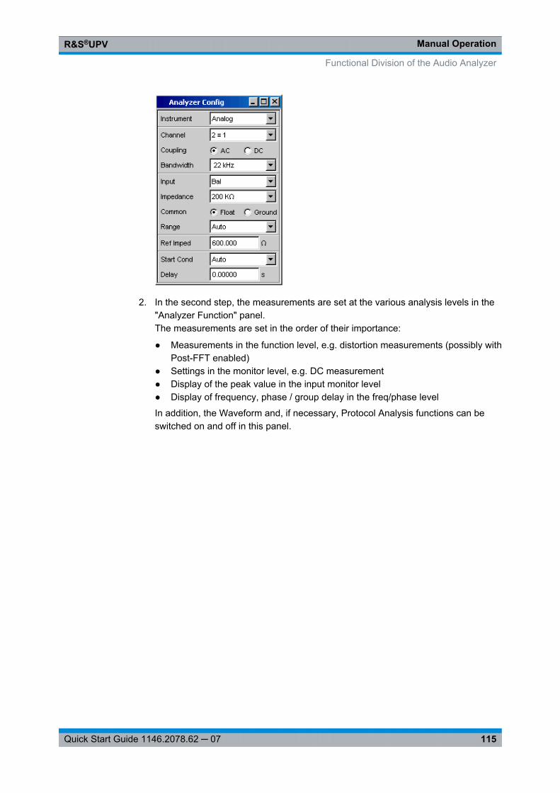
Manual OperationR&S®UPV
115Quick Start Guide 1146.2078.62 ─ 07
2. In the second step, the measurements are set at the various analysis levels in the"Analyzer Function" panel.The measurements are set in the order of their importance:
● Measurements in the function level, e.g. distortion measurements (possibly withPost-FFT enabled)
● Settings in the monitor level, e.g. DC measurement● Display of the peak value in the input monitor level● Display of frequency, phase / group delay in the freq/phase level
In addition, the Waveform and, if necessary, Protocol Analysis functions can beswitched on and off in this panel.
Functional Division of the Audio Analyzer
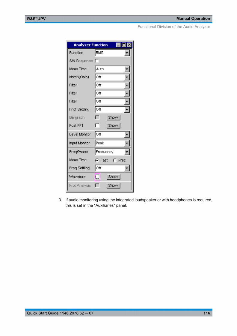
Manual OperationR&S®UPV
116Quick Start Guide 1146.2078.62 ─ 07
3. If audio monitoring using the integrated loudspeaker or with headphones is required,this is set in the "Auxiliaries" panel.
Functional Division of the Audio Analyzer
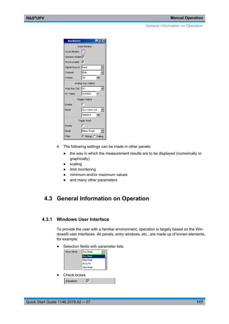
Manual OperationR&S®UPV
117Quick Start Guide 1146.2078.62 ─ 07
4. The following settings can be made in other panels:
● the way in which the measurement results are to be displayed (numerically orgraphically)
● scaling● limit monitoring● minimum and/or maximum values● and many other parameters
4.3 General Information on Operation
4.3.1 Windows User Interface
To provide the user with a familiar environment, operation is largely based on the Win-dows® user interfaces. All panels, entry windows, etc., are made up of known elements,for example:
● Selection fields with parameter lists
● Check boxes
General Information on Operation
Manual OperationR&S®UPV
118Quick Start Guide 1146.2078.62 ─ 07
● Radio buttons
● Entry fields
A blue, green or magenta selection frame or the highlighting of an entry field (dark back-ground) indicates the current entry focus. Entries can be made in the element with entryfocus.
Operation follows the same basic rules which apply to other Windows programs in usetoday. It is assumed that the user is familiar with these basic rules. This information istherefore not given in detail in this manual.
4.3.2 Using the Rotary Knob
Operation is possible using the front-panel keys, an external keyboard and/or a mouse.However, most of the settings can be made with the rotary knob:● Turning the rotary knob shifts the entry focus to the desired element.● Pressing the rotary knob (rotary-knob click) opens the parameter list in the selection
fields; a parameter can be selected from the list by again turning and then clickingwith the rotary knob.
● Check boxes are activated/deactivated by clicking with the rotary knob.● The individual radio buttons are selected by turning the rotary knob; they are toggled
by clicking with the rotary knob.● In the entry fields, the numeric values can be changed directly (with immediate effect
on the setting) or first edited and then adopted by clicking again with the rotary knob.
4.3.3 Operation Using the Mouse
Similar to other Windows® programs, the R&S UPV can also be operated with a mouse.To permit this, a commercially available mouse (not supplied with the instrument) is con-nected to one of the four USB interfaces at the front or rear of the instrument (see chap-ter 2.7.2, "Connecting an External Mouse", on page 33).
The mouse makes it easier to move and resize the panels and graphical windows on thescreen and provides alternative operating modes. It allows easy operation of Windows®.
Specifically for mouse operation, the R&S UPV also features a menu bar that either canbe displayed permanently at the top of the screen or appear at the top of the screen assoon as the mouse pointer is moved to the left side of the screen, and a toolbar that eithercan be displayed permanently at the top edge of the screen of appear at the right side ofthe screen as soon as the mouse pointer is moved there. In both cases, the permanentdisplay is set in the config panel under the heading "Always visible". This tool bar containsa number of icons for calling up frequently used functions.
The functions of the mouse correspond to the following front-panel functions:
General Information on Operation
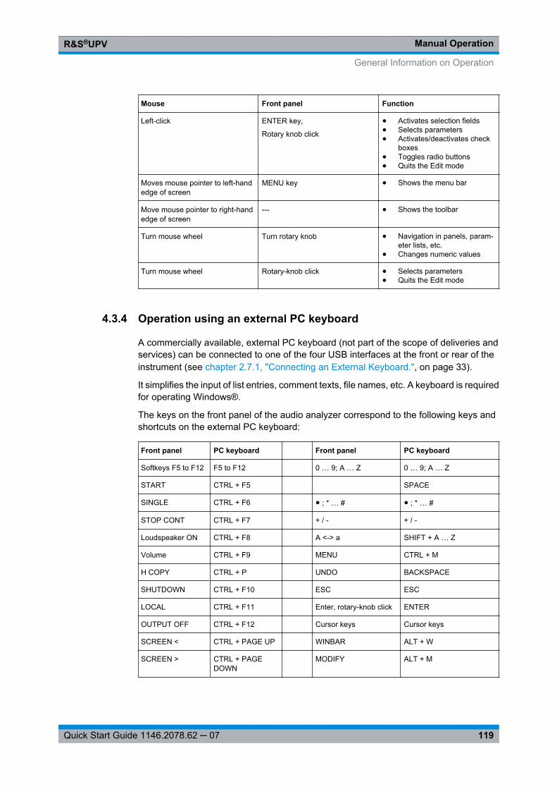
Manual OperationR&S®UPV
119Quick Start Guide 1146.2078.62 ─ 07
Mouse Front panel Function
Left-click ENTER key,
Rotary knob click
● Activates selection fields● Selects parameters● Activates/deactivates check
boxes● Toggles radio buttons● Quits the Edit mode
Moves mouse pointer to left-handedge of screen
MENU key ● Shows the menu bar
Move mouse pointer to right-handedge of screen
--- ● Shows the toolbar
Turn mouse wheel Turn rotary knob ● Navigation in panels, param-eter lists, etc.
● Changes numeric values
Turn mouse wheel Rotary-knob click ● Selects parameters● Quits the Edit mode
4.3.4 Operation using an external PC keyboard
A commercially available, external PC keyboard (not part of the scope of deliveries andservices) can be connected to one of the four USB interfaces at the front or rear of theinstrument (see chapter 2.7.1, "Connecting an External Keyboard.", on page 33).
It simplifies the input of list entries, comment texts, file names, etc. A keyboard is requiredfor operating Windows®.
The keys on the front panel of the audio analyzer correspond to the following keys andshortcuts on the external PC keyboard:
Front panel PC keyboard Front panel PC keyboard
Softkeys F5 to F12 F5 to F12 0 … 9; A … Z 0 … 9; A … Z
START CTRL + F5 SPACE
SINGLE CTRL + F6 ● ; * … # ● ; * … #
STOP CONT CTRL + F7 + / - + / -
Loudspeaker ON CTRL + F8 A <-> a SHIFT + A … Z
Volume CTRL + F9 MENU CTRL + M
H COPY CTRL + P UNDO BACKSPACE
SHUTDOWN CTRL + F10 ESC ESC
LOCAL CTRL + F11 Enter, rotary-knob click ENTER
OUTPUT OFF CTRL + F12 Cursor keys Cursor keys
SCREEN < CTRL + PAGE UP WINBAR ALT + W
SCREEN > CTRL + PAGEDOWN
MODIFY ALT + M
General Information on Operation
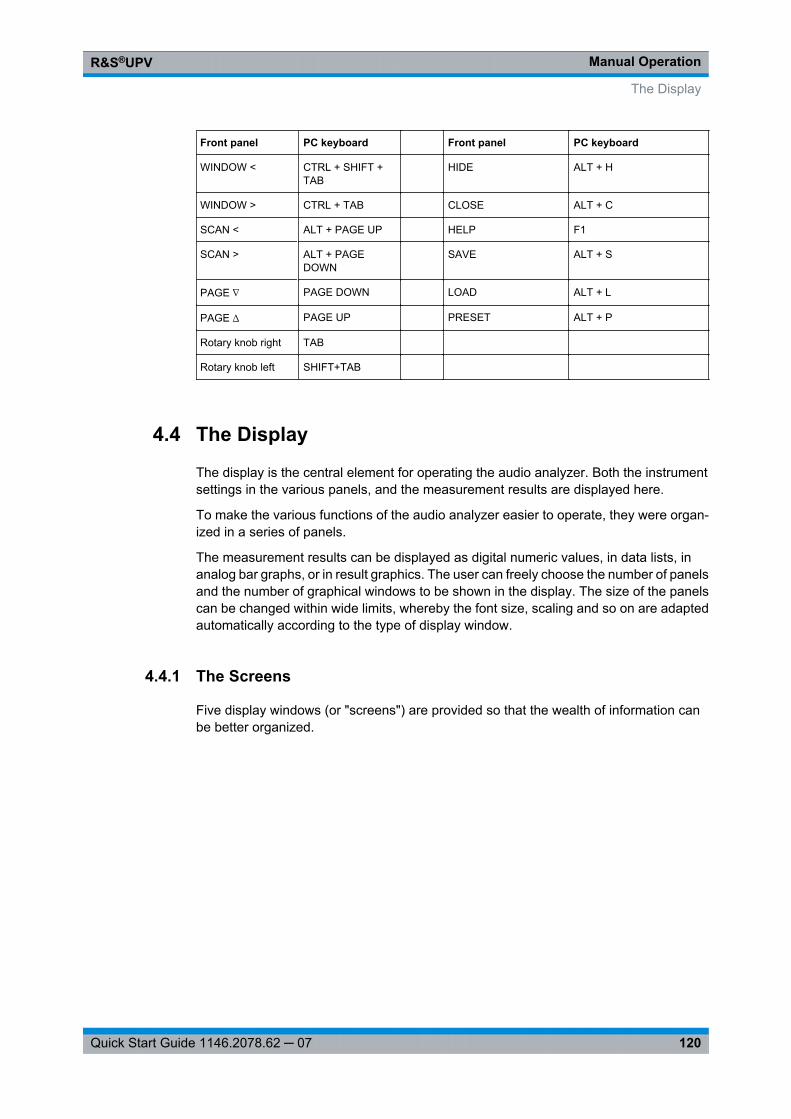
Manual OperationR&S®UPV
120Quick Start Guide 1146.2078.62 ─ 07
Front panel PC keyboard Front panel PC keyboard
WINDOW < CTRL + SHIFT +TAB
HIDE ALT + H
WINDOW > CTRL + TAB CLOSE ALT + C
SCAN < ALT + PAGE UP HELP F1
SCAN > ALT + PAGEDOWN
SAVE ALT + S
PAGE ∇ PAGE DOWN LOAD ALT + L
PAGE ∆ PAGE UP PRESET ALT + P
Rotary knob right TAB
Rotary knob left SHIFT+TAB
4.4 The Display
The display is the central element for operating the audio analyzer. Both the instrumentsettings in the various panels, and the measurement results are displayed here.
To make the various functions of the audio analyzer easier to operate, they were organ-ized in a series of panels.
The measurement results can be displayed as digital numeric values, in data lists, inanalog bar graphs, or in result graphics. The user can freely choose the number of panelsand the number of graphical windows to be shown in the display. The size of the panelscan be changed within wide limits, whereby the font size, scaling and so on are adaptedautomatically according to the type of display window.
4.4.1 The Screens
Five display windows (or "screens") are provided so that the wealth of information canbe better organized.
The Display
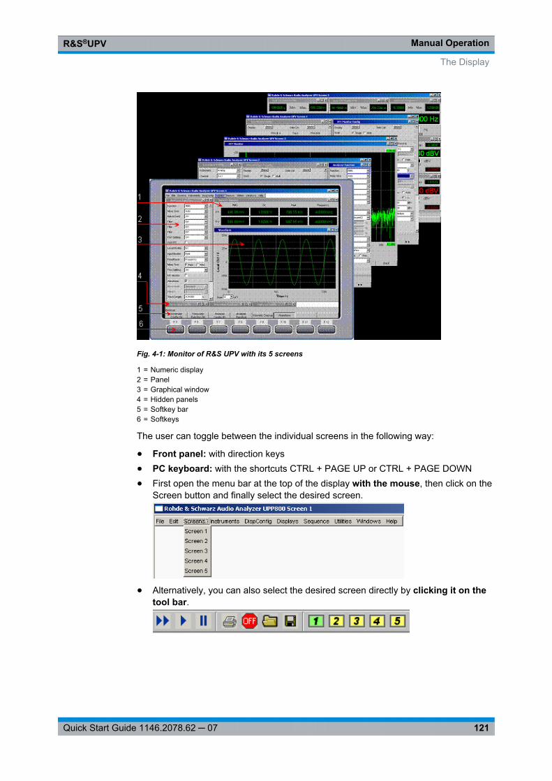
Manual OperationR&S®UPV
121Quick Start Guide 1146.2078.62 ─ 07
Fig. 4-1: Monitor of R&S UPV with its 5 screens
1 = Numeric display2 = Panel3 = Graphical window4 = Hidden panels5 = Softkey bar6 = Softkeys
The user can toggle between the individual screens in the following way:
● Front panel: with direction keys● PC keyboard: with the shortcuts CTRL + PAGE UP or CTRL + PAGE DOWN● First open the menu bar at the top of the display with the mouse, then click on the
Screen button and finally select the desired screen.
● Alternatively, you can also select the desired screen directly by clicking it on thetool bar.
The Display
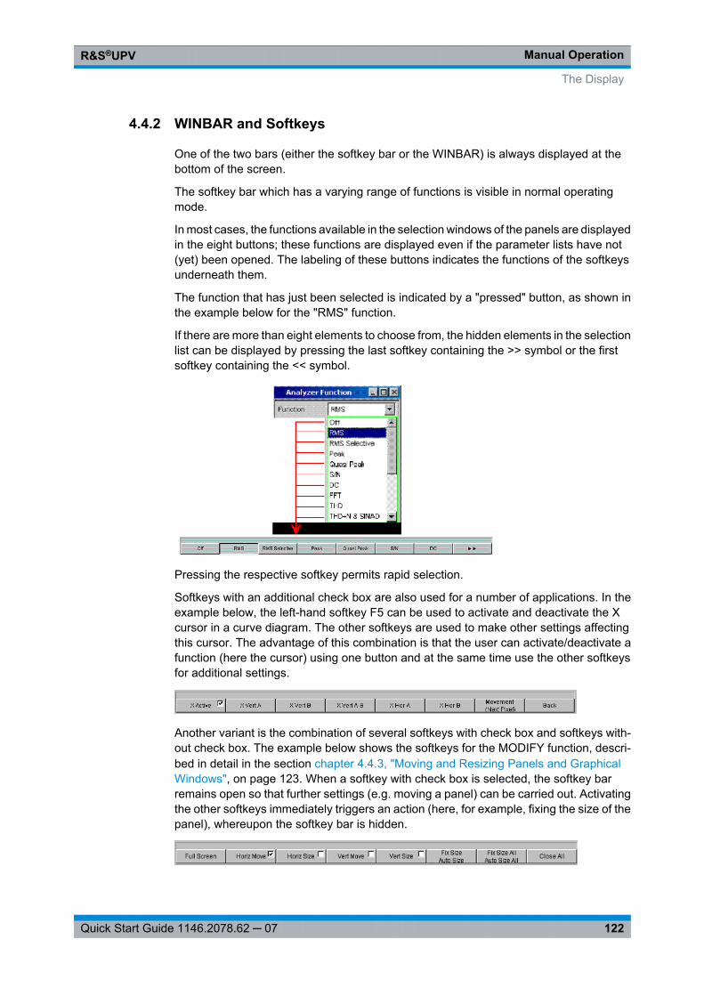
Manual OperationR&S®UPV
122Quick Start Guide 1146.2078.62 ─ 07
4.4.2 WINBAR and Softkeys
One of the two bars (either the softkey bar or the WINBAR) is always displayed at thebottom of the screen.
The softkey bar which has a varying range of functions is visible in normal operatingmode.
In most cases, the functions available in the selection windows of the panels are displayedin the eight buttons; these functions are displayed even if the parameter lists have not(yet) been opened. The labeling of these buttons indicates the functions of the softkeysunderneath them.
The function that has just been selected is indicated by a "pressed" button, as shown inthe example below for the "RMS" function.
If there are more than eight elements to choose from, the hidden elements in the selectionlist can be displayed by pressing the last softkey containing the >> symbol or the firstsoftkey containing the << symbol.
Pressing the respective softkey permits rapid selection.
Softkeys with an additional check box are also used for a number of applications. In theexample below, the left-hand softkey F5 can be used to activate and deactivate the Xcursor in a curve diagram. The other softkeys are used to make other settings affectingthis cursor. The advantage of this combination is that the user can activate/deactivate afunction (here the cursor) using one button and at the same time use the other softkeysfor additional settings.
Another variant is the combination of several softkeys with check box and softkeys with-out check box. The example below shows the softkeys for the MODIFY function, descri-bed in detail in the section chapter 4.4.3, "Moving and Resizing Panels and GraphicalWindows", on page 123. When a softkey with check box is selected, the softkey barremains open so that further settings (e.g. moving a panel) can be carried out. Activatingthe other softkeys immediately triggers an action (here, for example, fixing the size of thepanel), whereupon the softkey bar is hidden.
The Display
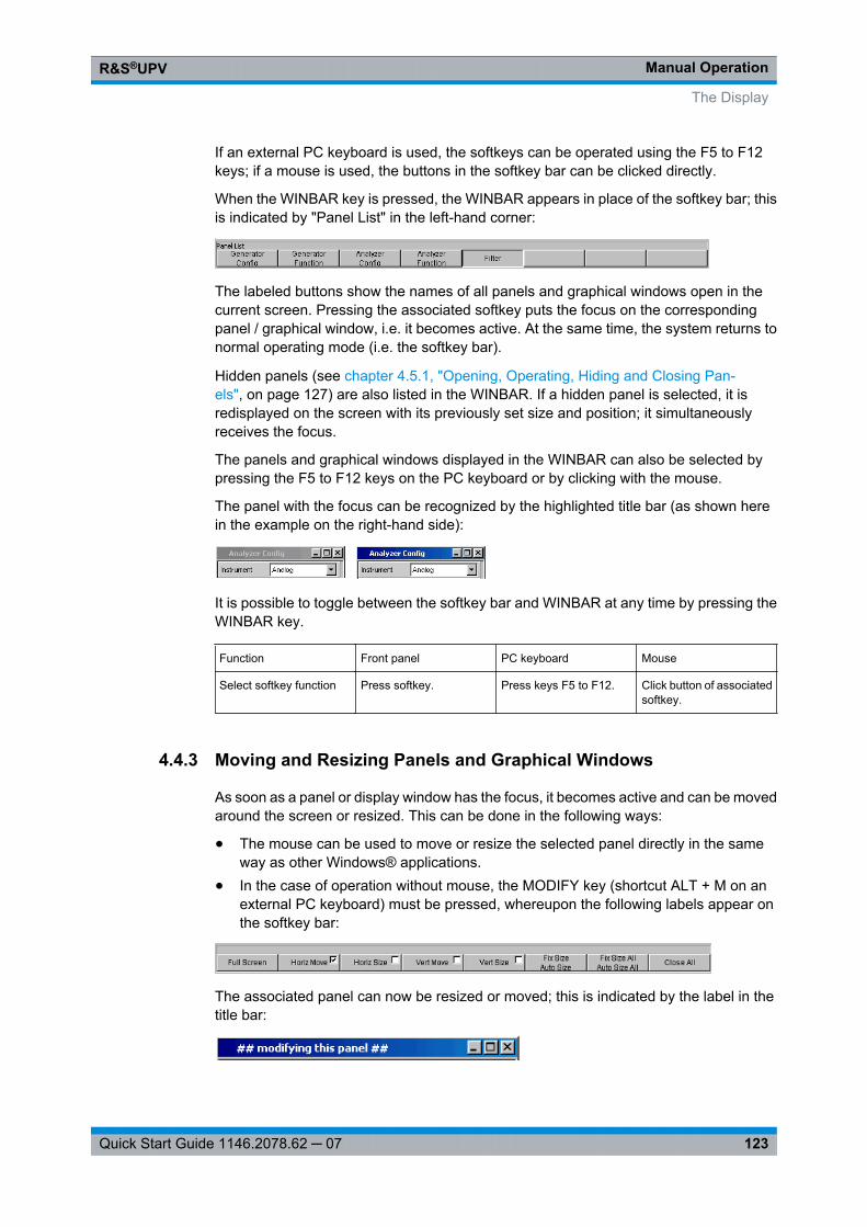
Manual OperationR&S®UPV
123Quick Start Guide 1146.2078.62 ─ 07
If an external PC keyboard is used, the softkeys can be operated using the F5 to F12keys; if a mouse is used, the buttons in the softkey bar can be clicked directly.
When the WINBAR key is pressed, the WINBAR appears in place of the softkey bar; thisis indicated by "Panel List" in the left-hand corner:
The labeled buttons show the names of all panels and graphical windows open in thecurrent screen. Pressing the associated softkey puts the focus on the correspondingpanel / graphical window, i.e. it becomes active. At the same time, the system returns tonormal operating mode (i.e. the softkey bar).
Hidden panels (see chapter 4.5.1, "Opening, Operating, Hiding and Closing Pan-els", on page 127) are also listed in the WINBAR. If a hidden panel is selected, it isredisplayed on the screen with its previously set size and position; it simultaneouslyreceives the focus.
The panels and graphical windows displayed in the WINBAR can also be selected bypressing the F5 to F12 keys on the PC keyboard or by clicking with the mouse.
The panel with the focus can be recognized by the highlighted title bar (as shown herein the example on the right-hand side):
It is possible to toggle between the softkey bar and WINBAR at any time by pressing theWINBAR key.
Function Front panel PC keyboard Mouse
Select softkey function Press softkey. Press keys F5 to F12. Click button of associatedsoftkey.
4.4.3 Moving and Resizing Panels and Graphical Windows
As soon as a panel or display window has the focus, it becomes active and can be movedaround the screen or resized. This can be done in the following ways:
● The mouse can be used to move or resize the selected panel directly in the sameway as other Windows® applications.
● In the case of operation without mouse, the MODIFY key (shortcut ALT + M on anexternal PC keyboard) must be pressed, whereupon the following labels appear onthe softkey bar:
The associated panel can now be resized or moved; this is indicated by the label in thetitle bar:
The Display
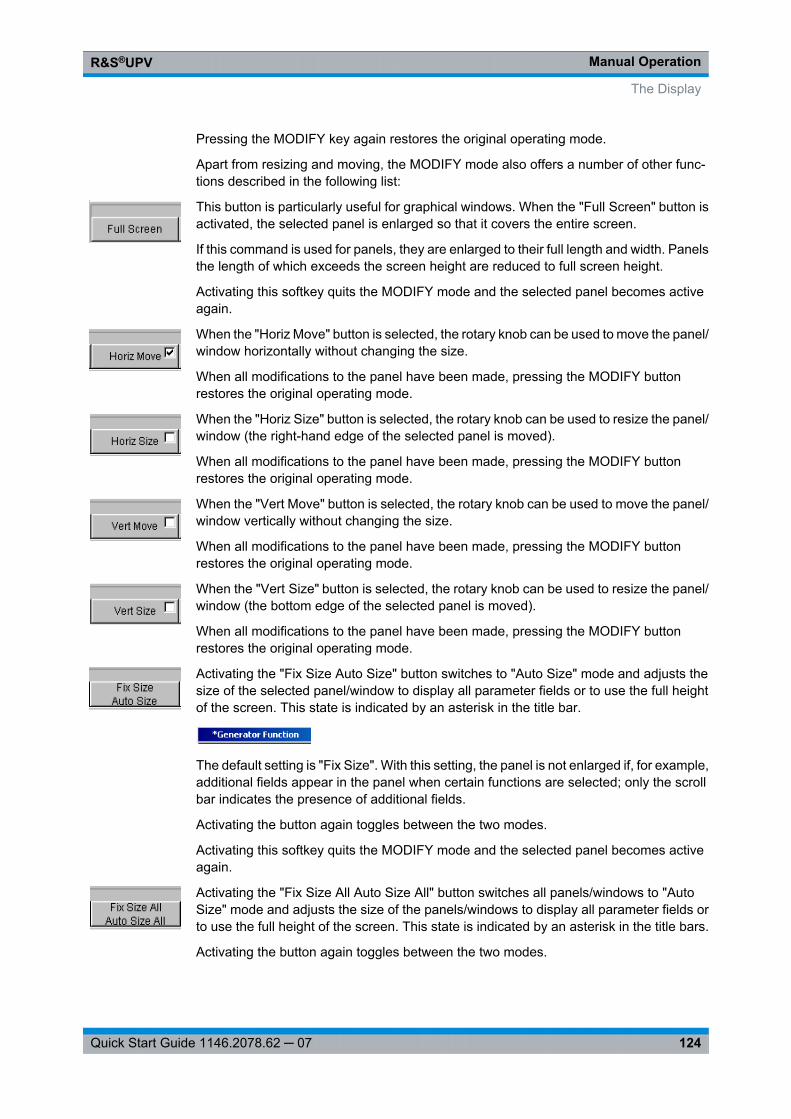
Manual OperationR&S®UPV
124Quick Start Guide 1146.2078.62 ─ 07
Pressing the MODIFY key again restores the original operating mode.
Apart from resizing and moving, the MODIFY mode also offers a number of other func-tions described in the following list:
This button is particularly useful for graphical windows. When the "Full Screen" button isactivated, the selected panel is enlarged so that it covers the entire screen.
If this command is used for panels, they are enlarged to their full length and width. Panelsthe length of which exceeds the screen height are reduced to full screen height.
Activating this softkey quits the MODIFY mode and the selected panel becomes activeagain.
When the "Horiz Move" button is selected, the rotary knob can be used to move the panel/window horizontally without changing the size.
When all modifications to the panel have been made, pressing the MODIFY buttonrestores the original operating mode.
When the "Horiz Size" button is selected, the rotary knob can be used to resize the panel/window (the right-hand edge of the selected panel is moved).
When all modifications to the panel have been made, pressing the MODIFY buttonrestores the original operating mode.
When the "Vert Move" button is selected, the rotary knob can be used to move the panel/window vertically without changing the size.
When all modifications to the panel have been made, pressing the MODIFY buttonrestores the original operating mode.
When the "Vert Size" button is selected, the rotary knob can be used to resize the panel/window (the bottom edge of the selected panel is moved).
When all modifications to the panel have been made, pressing the MODIFY buttonrestores the original operating mode.
Activating the "Fix Size Auto Size" button switches to "Auto Size" mode and adjusts thesize of the selected panel/window to display all parameter fields or to use the full heightof the screen. This state is indicated by an asterisk in the title bar.
The default setting is "Fix Size". With this setting, the panel is not enlarged if, for example,additional fields appear in the panel when certain functions are selected; only the scrollbar indicates the presence of additional fields.
Activating the button again toggles between the two modes.
Activating this softkey quits the MODIFY mode and the selected panel becomes activeagain.
Activating the "Fix Size All Auto Size All" button switches all panels/windows to "AutoSize" mode and adjusts the size of the panels/windows to display all parameter fields orto use the full height of the screen. This state is indicated by an asterisk in the title bars.
Activating the button again toggles between the two modes.
The Display
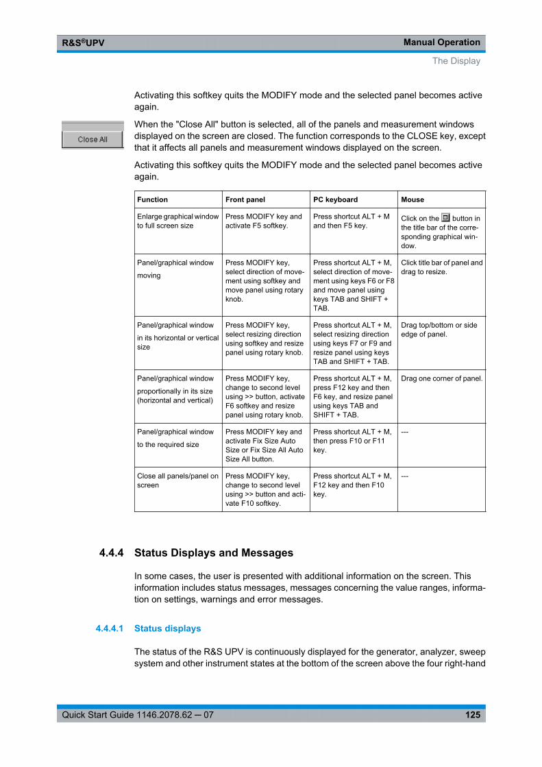
Manual OperationR&S®UPV
125Quick Start Guide 1146.2078.62 ─ 07
Activating this softkey quits the MODIFY mode and the selected panel becomes activeagain.
When the "Close All" button is selected, all of the panels and measurement windowsdisplayed on the screen are closed. The function corresponds to the CLOSE key, exceptthat it affects all panels and measurement windows displayed on the screen.
Activating this softkey quits the MODIFY mode and the selected panel becomes activeagain.
Function Front panel PC keyboard Mouse
Enlarge graphical windowto full screen size
Press MODIFY key andactivate F5 softkey.
Press shortcut ALT + Mand then F5 key.
Click on the button inthe title bar of the corre-sponding graphical win-dow.
Panel/graphical window
moving
Press MODIFY key,select direction of move-ment using softkey andmove panel using rotaryknob.
Press shortcut ALT + M,select direction of move-ment using keys F6 or F8and move panel usingkeys TAB and SHIFT +TAB.
Click title bar of panel anddrag to resize.
Panel/graphical window
in its horizontal or verticalsize
Press MODIFY key,select resizing directionusing softkey and resizepanel using rotary knob.
Press shortcut ALT + M,select resizing directionusing keys F7 or F9 andresize panel using keysTAB and SHIFT + TAB.
Drag top/bottom or sideedge of panel.
Panel/graphical window
proportionally in its size(horizontal and vertical)
Press MODIFY key,change to second levelusing >> button, activateF6 softkey and resizepanel using rotary knob.
Press shortcut ALT + M,press F12 key and thenF6 key, and resize panelusing keys TAB andSHIFT + TAB.
Drag one corner of panel.
Panel/graphical window
to the required size
Press MODIFY key andactivate Fix Size AutoSize or Fix Size All AutoSize All button.
Press shortcut ALT + M,then press F10 or F11key.
---
Close all panels/panel onscreen
Press MODIFY key,change to second levelusing >> button and acti-vate F10 softkey.
Press shortcut ALT + M,F12 key and then F10key.
---
4.4.4 Status Displays and Messages
In some cases, the user is presented with additional information on the screen. Thisinformation includes status messages, messages concerning the value ranges, informa-tion on settings, warnings and error messages.
4.4.4.1 Status displays
The status of the R&S UPV is continuously displayed for the generator, analyzer, sweepsystem and other instrument states at the bottom of the screen above the four right-hand
The Display
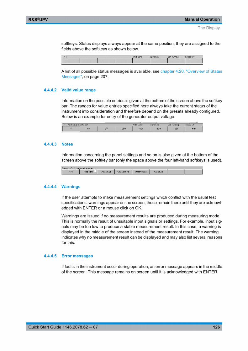
Manual OperationR&S®UPV
126Quick Start Guide 1146.2078.62 ─ 07
softkeys. Status displays always appear at the same position; they are assigned to thefields above the softkeys as shown below.
A list of all possible status messages is available, see chapter 4.20, "Overview of StatusMessages", on page 207.
4.4.4.2 Valid value range
Information on the possible entries is given at the bottom of the screen above the softkeybar. The ranges for value entries specified here always take the current status of theinstrument into consideration and therefore depend on the presets already configured.Below is an example for entry of the generator output voltage:
4.4.4.3 Notes
Information concerning the panel settings and so on is also given at the bottom of thescreen above the softkey bar (only the space above the four left-hand softkeys is used).
4.4.4.4 Warnings
If the user attempts to make measurement settings which conflict with the usual testspecifications, warnings appear on the screen; these remain there until they are acknowl-edged with ENTER or a mouse click on OK.
Warnings are issued if no measurement results are produced during measuring mode.This is normally the result of unsuitable input signals or settings. For example, input sig-nals may be too low to produce a stable measurement result. In this case, a warning isdisplayed in the middle of the screen instead of the measurement result. The warningindicates why no measurement result can be displayed and may also list several reasonsfor this.
4.4.4.5 Error messages
If faults in the instrument occur during operation, an error message appears in the middleof the screen. This message remains on screen until it is acknowledged with ENTER.
The Display
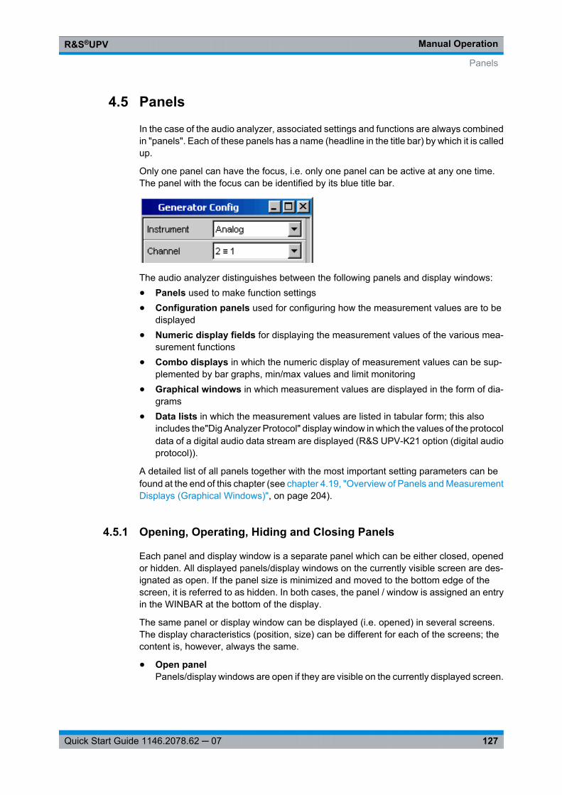
Manual OperationR&S®UPV
127Quick Start Guide 1146.2078.62 ─ 07
4.5 Panels
In the case of the audio analyzer, associated settings and functions are always combinedin "panels". Each of these panels has a name (headline in the title bar) by which it is calledup.
Only one panel can have the focus, i.e. only one panel can be active at any one time.The panel with the focus can be identified by its blue title bar.
The audio analyzer distinguishes between the following panels and display windows:● Panels used to make function settings● Configuration panels used for configuring how the measurement values are to be
displayed● Numeric display fields for displaying the measurement values of the various mea-
surement functions● Combo displays in which the numeric display of measurement values can be sup-
plemented by bar graphs, min/max values and limit monitoring● Graphical windows in which measurement values are displayed in the form of dia-
grams● Data lists in which the measurement values are listed in tabular form; this also
includes the"Dig Analyzer Protocol" display window in which the values of the protocoldata of a digital audio data stream are displayed (R&S UPV-K21 option (digital audioprotocol)).
A detailed list of all panels together with the most important setting parameters can befound at the end of this chapter (see chapter 4.19, "Overview of Panels and MeasurementDisplays (Graphical Windows)", on page 204).
4.5.1 Opening, Operating, Hiding and Closing Panels
Each panel and display window is a separate panel which can be either closed, openedor hidden. All displayed panels/display windows on the currently visible screen are des-ignated as open. If the panel size is minimized and moved to the bottom edge of thescreen, it is referred to as hidden. In both cases, the panel / window is assigned an entryin the WINBAR at the bottom of the display.
The same panel or display window can be displayed (i.e. opened) in several screens.The display characteristics (position, size) can be different for each of the screens; thecontent is, however, always the same.
● Open panelPanels/display windows are open if they are visible on the currently displayed screen.
Panels
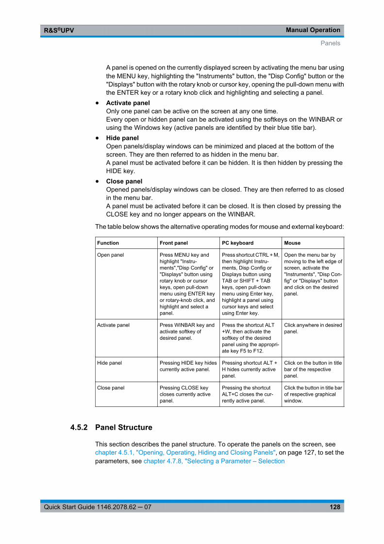
Manual OperationR&S®UPV
128Quick Start Guide 1146.2078.62 ─ 07
A panel is opened on the currently displayed screen by activating the menu bar usingthe MENU key, highlighting the "Instruments" button, the "Disp Config" button or the"Displays" button with the rotary knob or cursor key, opening the pull-down menu withthe ENTER key or a rotary knob click and highlighting and selecting a panel.
● Activate panelOnly one panel can be active on the screen at any one time.Every open or hidden panel can be activated using the softkeys on the WINBAR orusing the Windows key (active panels are identified by their blue title bar).
● Hide panelOpen panels/display windows can be minimized and placed at the bottom of thescreen. They are then referred to as hidden in the menu bar.A panel must be activated before it can be hidden. It is then hidden by pressing theHIDE key.
● Close panelOpened panels/display windows can be closed. They are then referred to as closedin the menu bar.A panel must be activated before it can be closed. It is then closed by pressing theCLOSE key and no longer appears on the WINBAR.
The table below shows the alternative operating modes for mouse and external keyboard:
Function Front panel PC keyboard Mouse
Open panel Press MENU key andhighlight "Instru-ments","Disp Config" or"Displays" button usingrotary knob or cursorkeys, open pull-downmenu using ENTER keyor rotary-knob click, andhighlight and select apanel.
Press shortcut CTRL + M,then highlight Instru-ments, Disp Config orDisplays button usingTAB or SHIFT + TABkeys, open pull-downmenu using Enter key,highlight a panel usingcursor keys and selectusing Enter key.
Open the menu bar bymoving to the left edge ofscreen, activate the"Instruments", "Disp Con-fig" or "Displays" buttonand click on the desiredpanel.
Activate panel Press WINBAR key andactivate softkey ofdesired panel.
Press the shortcut ALT+W, then activate thesoftkey of the desiredpanel using the appropri-ate key F5 to F12.
Click anywhere in desiredpanel.
Hide panel Pressing HIDE key hidescurrently active panel.
Pressing shortcut ALT +H hides currently activepanel.
Click on the button in titlebar of the respectivepanel.
Close panel Pressing CLOSE keycloses currently activepanel.
Pressing the shortcutALT+C closes the cur-rently active panel.
Click the button in title barof respective graphicalwindow.
4.5.2 Panel Structure
This section describes the panel structure. To operate the panels on the screen, see chapter 4.5.1, "Opening, Operating, Hiding and Closing Panels", on page 127, to set theparameters, see chapter 4.7.8, "Selecting a Parameter – Selection
Panels
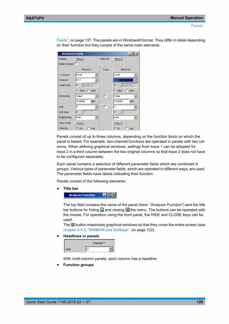
Manual OperationR&S®UPV
129Quick Start Guide 1146.2078.62 ─ 07
Fields", on page 137. The panels are in Windows® format. They differ in detail dependingon their function but they consist of the same main elements.
Panels consist of up to three columns, depending on the function block on which thepanel is based. For example, two-channel functions are operated in panels with two col-umns. When defining graphical windows, settings from trace 1 can be adopted fortrace 2 in a third column between the two original columns so that trace 2 does not haveto be configured separately.
Each panel contains a selection of different parameter fields which are combined ingroups. Various types of parameter fields, which are operated in different ways, are used.The parameter fields have labels indicating their function.
Panels consist of the following elements:
● Title bar
The top field contains the name of the panel (here: "Analyzer Function") and the titlebar buttons for hiding and closing the menu. The buttons can be operated withthe mouse. For operation using the front panel, the HIDE and CLOSE keys can beused.The button maximizes graphical windows so that they cover the entire screen (seechapter 4.4.2, "WINBAR and Softkeys", on page 122).
● Headlines in panels
With multi-column panels, each column has a headline.● Function groups
Panels
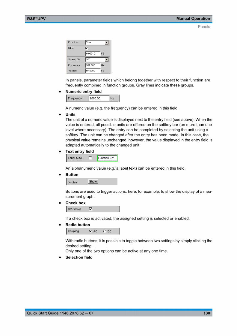
Manual OperationR&S®UPV
130Quick Start Guide 1146.2078.62 ─ 07
In panels, parameter fields which belong together with respect to their function arefrequently combined in function groups. Gray lines indicate these groups.
● Numeric entry field
A numeric value (e.g. the frequency) can be entered in this field.● Units
The unit of a numeric value is displayed next to the entry field (see above). When thevalue is entered, all possible units are offered on the softkey bar (on more than onelevel where necessary). The entry can be completed by selecting the unit using asoftkey. The unit can be changed after the entry has been made. In this case, thephysical value remains unchanged; however, the value displayed in the entry field isadapted automatically to the changed unit.
● Text entry field
An alphanumeric value (e.g. a label text) can be entered in this field.● Button
Buttons are used to trigger actions; here, for example, to show the display of a mea-surement graph.
● Check box
If a check box is activated, the assigned setting is selected or enabled.● Radio button
With radio buttons, it is possible to toggle between two settings by simply clicking thedesired setting.Only one of the two options can be active at any one time.
● Selection field
Panels
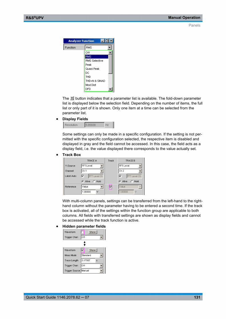
Manual OperationR&S®UPV
131Quick Start Guide 1146.2078.62 ─ 07
The button indicates that a parameter list is available. The fold-down parameterlist is displayed below the selection field. Depending on the number of items, the fulllist or only part of it is shown. Only one item at a time can be selected from theparameter list.
● Display Fields
Some settings can only be made in a specific configuration. If the setting is not per-mitted with the specific configuration selected, the respective item is disabled anddisplayed in gray and the field cannot be accessed. In this case, the field acts as adisplay field, i.e. the value displayed there corresponds to the value actually set.
● Track Box
With multi-column panels, settings can be transferred from the left-hand to the right-hand column without the parameter having to be entered a second time. If the trackbox is activated, all of the settings within the function group are applicable to bothcolumns. All fields with transferred settings are shown as display fields and cannotbe accessed while the track function is active.
● Hidden parameter fields
Panels
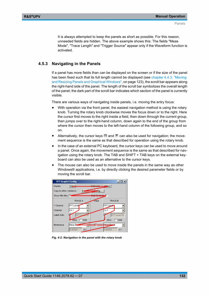
Manual OperationR&S®UPV
132Quick Start Guide 1146.2078.62 ─ 07
It is always attempted to keep the panels as short as possible. For this reason,unneeded fields are hidden. The above example shows this: The fields "MeasMode", "Trace Length" and "Trigger Source" appear only if the Waveform function isactivated.
4.5.3 Navigating in the Panels
If a panel has more fields than can be displayed on the screen or if the size of the panelhas been fixed such that its full length cannot be displayed (see chapter 4.4.3, "Movingand Resizing Panels and Graphical Windows", on page 123), the scroll bar appears alongthe right-hand side of the panel. The length of the scroll bar symbolizes the overall lengthof the panel; the dark part of the scroll bar indicates which section of the panel is currentlyvisible.
There are various ways of navigating inside panels, i.e. moving the entry focus:● With operation via the front panel, the easiest navigation method is using the rotary
knob. Turning the rotary knob clockwise moves the focus down or to the right. Herethe cursor first moves to the right inside a field, then down through the current group,then jumps over to the right-hand column, down again to the end of the group fromwhere the cursor then moves to the left-hand column of the following group, and soon.
● Alternatively, the cursor keys and can also be used for navigation; the move-ment sequence is the same as that described for operation using the rotary knob.
● In the case of an external PC keyboard, the cursor keys can be used to move arounda panel. Once again, the movement sequence is the same as that described for nav-igation using the rotary knob. The TAB and SHIFT + TAB keys on the external key-board can also be used as an alternative to the cursor keys.
● The mouse can also be used to move inside the panels in the same way as otherWindows® applications, i.e. by directly clicking the desired parameter fields or bymoving the scroll bar.
Fig. 4-2: Navigation in the panel with the rotary knob
Panels
Manual OperationR&S®UPV
133Quick Start Guide 1146.2078.62 ─ 07
4.6 Settings on the Audio Analyzer
The R&S UPV offers several and sometimes alternative options for setting parameters.Operation is possible from the front panel, with the aid of a mouse and/or from a PCkeyboard (see chapter 4.3, "General Information on Operation", on page 117). The tablesbelow list the operating options with the available entry media.
Some keys on the front panel of the R&S UPV directly initiate a setting, e.g. the OUTPUTOFF key switches the outputs off or on again. An overview showing the function of allkeys can be found at the end of this chapter (see chapter 4.18, "Overview ofKeys", on page 200).
Most of the parameters are set in the panels. The panels are operated on the screen asdescribed in the section Opening, operating, hiding and closing panels. How to enter andselect setting parameters in the panels is described in the following sections, the detaileddescription of all setting parameters is located in the operating manual supplied on thedocumentation CD.
Entries for file management tasks, such as saving and loading instrument settings, savingfiles, and so on, are made in special panels, see chapter 4.15, "File Manage-ment", on page 188.
A number of settings are made via the menu bar. This includes all settings that configuredthe R&S UPV as a complete instrument, e.g. the setting of the IEC bus address, functionof the HCopy key, etc. For more detailed information, see chapter 4.9, "Settings in theMenu Bar", on page 175.
The R&S UPV is equipped with the Windows XP operating system. Settings at systemlevel are only rarely required, e.g. installation of a new printer driver. Connecting a key-board and mouse makes Windows easier to use.
4.7 Settings in the Panels
In the panels of the R&S UPV audio analyzer, associated settings and functions arecombined. Each function block has its own panel.
The panels can be set independently of each other; however, there are also a number ofinterdependencies. For example, the digital measurement function of the protocol analy-sis only appears in the "Analyzer Function" panel if a digital analyzer has been selectedin the "Analyzer Config" panel. If an analog analyzer is selected, the protocol analysis isautomatically deactivated in the "Analyzer Function" panel and a message is displayedon the screen.
4.7.1 Focus
Panels can only be operated if they have the focus (indicated by the blue title bar).
The simplest way of changing from one panel to another in the case of operation via thefront panel is using the direction keys . The > key switches from panel to panel in the
Settings on the Audio Analyzer
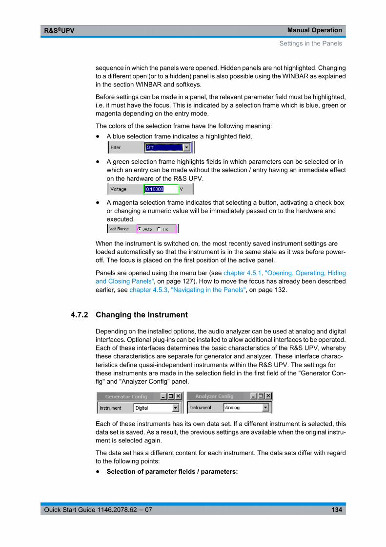
Manual OperationR&S®UPV
134Quick Start Guide 1146.2078.62 ─ 07
sequence in which the panels were opened. Hidden panels are not highlighted. Changingto a different open (or to a hidden) panel is also possible using the WINBAR as explainedin the section WINBAR and softkeys.
Before settings can be made in a panel, the relevant parameter field must be highlighted,i.e. it must have the focus. This is indicated by a selection frame which is blue, green ormagenta depending on the entry mode.
The colors of the selection frame have the following meaning:● A blue selection frame indicates a highlighted field.
● A green selection frame highlights fields in which parameters can be selected or inwhich an entry can be made without the selection / entry having an immediate effecton the hardware of the R&S UPV.
● A magenta selection frame indicates that selecting a button, activating a check boxor changing a numeric value will be immediately passed on to the hardware andexecuted.
When the instrument is switched on, the most recently saved instrument settings areloaded automatically so that the instrument is in the same state as it was before power-off. The focus is placed on the first position of the active panel.
Panels are opened using the menu bar (see chapter 4.5.1, "Opening, Operating, Hidingand Closing Panels", on page 127). How to move the focus has already been describedearlier, see chapter 4.5.3, "Navigating in the Panels", on page 132.
4.7.2 Changing the Instrument
Depending on the installed options, the audio analyzer can be used at analog and digitalinterfaces. Optional plug-ins can be installed to allow additional interfaces to be operated.Each of these interfaces determines the basic characteristics of the R&S UPV, wherebythese characteristics are separate for generator and analyzer. These interface charac-teristics define quasi-independent instruments within the R&S UPV. The settings forthese instruments are made in the selection field in the first field of the "Generator Con-fig" and "Analyzer Config" panel.
Each of these instruments has its own data set. If a different instrument is selected, thisdata set is saved. As a result, the previous settings are available when the original instru-ment is selected again.
The data set has a different content for each instrument. The data sets differ with regardto the following points:● Selection of parameter fields / parameters:
Settings in the Panels
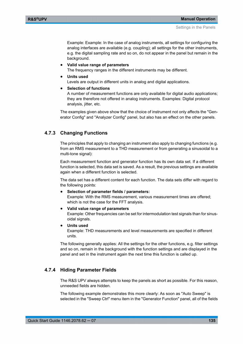
Manual OperationR&S®UPV
135Quick Start Guide 1146.2078.62 ─ 07
Example: Example: In the case of analog instruments, all settings for configuring theanalog interfaces are available (e.g. coupling); all settings for the other instruments,e.g. the digital sampling rate and so on, do not appear in the panel but remain in thebackground.
● Valid value range of parametersThe frequency ranges in the different instruments may be different.
● Units usedLevels are output in different units in analog and digital applications.
● Selection of functionsA number of measurement functions are only available for digital audio applications;they are therefore not offered in analog instruments. Examples: Digital protocolanalysis, jitter, etc.
The examples given above show that the choice of instrument not only affects the "Gen-erator Config" and "Analyzer Config" panel, but also has an effect on the other panels.
4.7.3 Changing Functions
The principles that apply to changing an instrument also apply to changing functions (e.g.from an RMS measurement to a THD measurement or from generating a sinusoidal to amulti-tone signal):
Each measurement function and generator function has its own data set. If a differentfunction is selected, this data set is saved. As a result, the previous settings are availableagain when a different function is selected.
The data set has a different content for each function. The data sets differ with regard tothe following points:● Selection of parameter fields / parameters:
Example: With the RMS measurement, various measurement times are offered;which is not the case for the FFT analysis.
● Valid value range of parametersExample: Other frequencies can be set for intermodulation test signals than for sinus-oidal signals.
● Units usedExample: THD measurements and level measurements are specified in differentunits.
The following generally applies: All the settings for the other functions, e.g. filter settingsand so on, remain in the background with the function settings and are displayed in thepanel and set in the instrument again the next time this function is called up.
4.7.4 Hiding Parameter Fields
The R&S UPV always attempts to keep the panels as short as possible. For this reason,unneeded fields are hidden.
The following example demonstrates this more clearly: As soon as "Auto Sweep" isselected in the "Sweep Ctrl" menu item in the "Generator Function" panel, all of the fields
Settings in the Panels
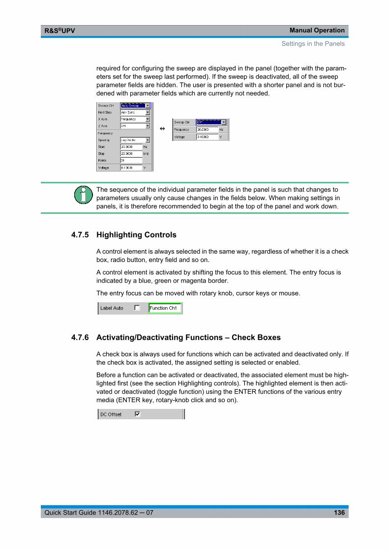
Manual OperationR&S®UPV
136Quick Start Guide 1146.2078.62 ─ 07
required for configuring the sweep are displayed in the panel (together with the param-eters set for the sweep last performed). If the sweep is deactivated, all of the sweepparameter fields are hidden. The user is presented with a shorter panel and is not bur-dened with parameter fields which are currently not needed.
The sequence of the individual parameter fields in the panel is such that changes toparameters usually only cause changes in the fields below. When making settings inpanels, it is therefore recommended to begin at the top of the panel and work down.
4.7.5 Highlighting Controls
A control element is always selected in the same way, regardless of whether it is a checkbox, radio button, entry field and so on.
A control element is activated by shifting the focus to this element. The entry focus isindicated by a blue, green or magenta border.
The entry focus can be moved with rotary knob, cursor keys or mouse.
4.7.6 Activating/Deactivating Functions – Check Boxes
A check box is always used for functions which can be activated and deactivated only. Ifthe check box is activated, the assigned setting is selected or enabled.
Before a function can be activated or deactivated, the associated element must be high-lighted first (see the section Highlighting controls). The highlighted element is then acti-vated or deactivated (toggle function) using the ENTER functions of the various entrymedia (ENTER key, rotary-knob click and so on).
Settings in the Panels
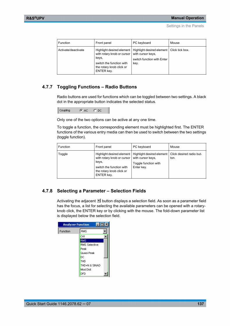
Manual OperationR&S®UPV
137Quick Start Guide 1146.2078.62 ─ 07
Function Front panel PC keyboard Mouse
Activate/deactivate Highlight desired elementwith rotary knob or cursorkeys,
switch the function withthe rotary knob click orENTER key.
Highlight desired elementwith cursor keys,
switch function with Enterkey.
Click tick box.
4.7.7 Toggling Functions – Radio Buttons
Radio buttons are used for functions which can be toggled between two settings. A blackdot in the appropriate button indicates the selected status.
Only one of the two options can be active at any one time.
To toggle a function, the corresponding element must be highlighted first. The ENTERfunctions of the various entry media can then be used to switch between the two settings(toggle function).
Function Front panel PC keyboard Mouse
Toggle Highlight desired elementwith rotary knob or cursorkeys,
switch the function withthe rotary knob click orENTER key.
Highlight desired elementwith cursor keys,
Toggle function withEnter key.
Click desired radio but-ton.
4.7.8 Selecting a Parameter – Selection Fields
Activating the adjacent button displays a selection field. As soon as a parameter fieldhas the focus, a list for selecting the available parameters can be opened with a rotary-knob click, the ENTER key or by clicking with the mouse. The fold-down parameter listis displayed below the selection field.
Settings in the Panels
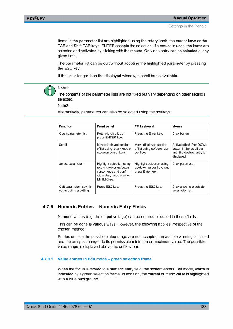
Manual OperationR&S®UPV
138Quick Start Guide 1146.2078.62 ─ 07
Items in the parameter list are highlighted using the rotary knob, the cursor keys or theTAB and Shift-TAB keys. ENTER accepts the selection. If a mouse is used, the items areselected and activated by clicking with the mouse. Only one entry can be selected at anygiven time.
The parameter list can be quit without adopting the highlighted parameter by pressingthe ESC key.
If the list is longer than the displayed window, a scroll bar is available.
Note1:The contents of the parameter lists are not fixed but vary depending on other settingsselected.Note2:Alternatively, parameters can also be selected using the softkeys.
Function Front panel PC keyboard Mouse
Open parameter list Rotary-knob click orpress ENTER key.
Press the Enter key. Click button.
Scroll Move displayed sectionof list using rotary knob orup/down cursor keys.
Move displayed sectionof list using up/down cur-sor keys.
Activate the UP or DOWNbutton in the scroll baruntil the desired entry isdisplayed.
Select parameter Highlight selection usingrotary knob or up/downcursor keys and confirmwith rotary-knob click orENTER key.
Highlight selection usingup/down cursor keys andpress Enter key.
Click parameter.
Quit parameter list with-out adopting a setting
Press ESC key. Press the ESC key. Click anywhere outsideparameter list.
4.7.9 Numeric Entries – Numeric Entry Fields
Numeric values (e.g. the output voltage) can be entered or edited in these fields.
This can be done is various ways. However, the following applies irrespective of thechosen method:
Entries outside the possible value range are not accepted; an audible warning is issuedand the entry is changed to its permissible minimum or maximum value. The possiblevalue range is displayed above the softkey bar.
4.7.9.1 Value entries in Edit mode – green selection frame
When the focus is moved to a numeric entry field, the system enters Edit mode, which isindicated by a green selection frame. In addition, the current numeric value is highlightedwith a blue background.
Settings in the Panels
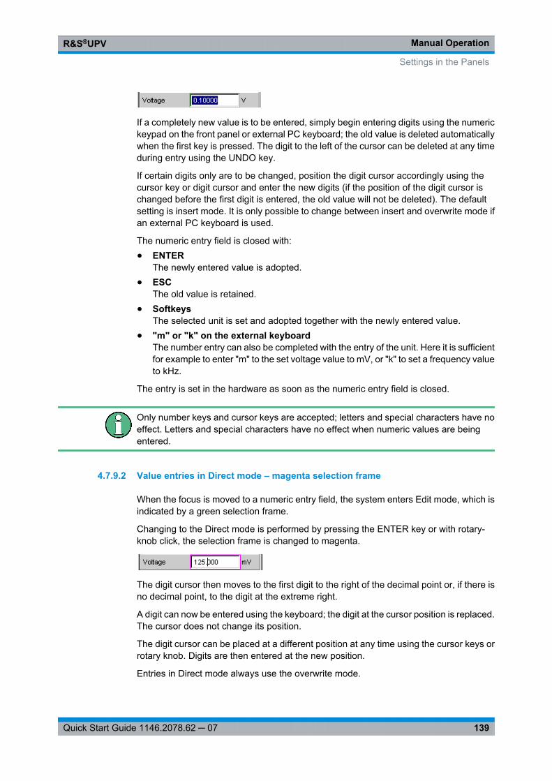
Manual OperationR&S®UPV
139Quick Start Guide 1146.2078.62 ─ 07
If a completely new value is to be entered, simply begin entering digits using the numerickeypad on the front panel or external PC keyboard; the old value is deleted automaticallywhen the first key is pressed. The digit to the left of the cursor can be deleted at any timeduring entry using the UNDO key.
If certain digits only are to be changed, position the digit cursor accordingly using thecursor key or digit cursor and enter the new digits (if the position of the digit cursor ischanged before the first digit is entered, the old value will not be deleted). The defaultsetting is insert mode. It is only possible to change between insert and overwrite mode ifan external PC keyboard is used.
The numeric entry field is closed with:● ENTER
The newly entered value is adopted.● ESC
The old value is retained.● Softkeys
The selected unit is set and adopted together with the newly entered value.● "m" or "k" on the external keyboard
The number entry can also be completed with the entry of the unit. Here it is sufficientfor example to enter "m" to the set voltage value to mV, or "k" to set a frequency valueto kHz.
The entry is set in the hardware as soon as the numeric entry field is closed.
Only number keys and cursor keys are accepted; letters and special characters have noeffect. Letters and special characters have no effect when numeric values are beingentered.
4.7.9.2 Value entries in Direct mode – magenta selection frame
When the focus is moved to a numeric entry field, the system enters Edit mode, which isindicated by a green selection frame.
Changing to the Direct mode is performed by pressing the ENTER key or with rotary-knob click, the selection frame is changed to magenta.
The digit cursor then moves to the first digit to the right of the decimal point or, if there isno decimal point, to the digit at the extreme right.
A digit can now be entered using the keyboard; the digit at the cursor position is replaced.The cursor does not change its position.
The digit cursor can be placed at a different position at any time using the cursor keys orrotary knob. Digits are then entered at the new position.
Entries in Direct mode always use the overwrite mode.
Settings in the Panels
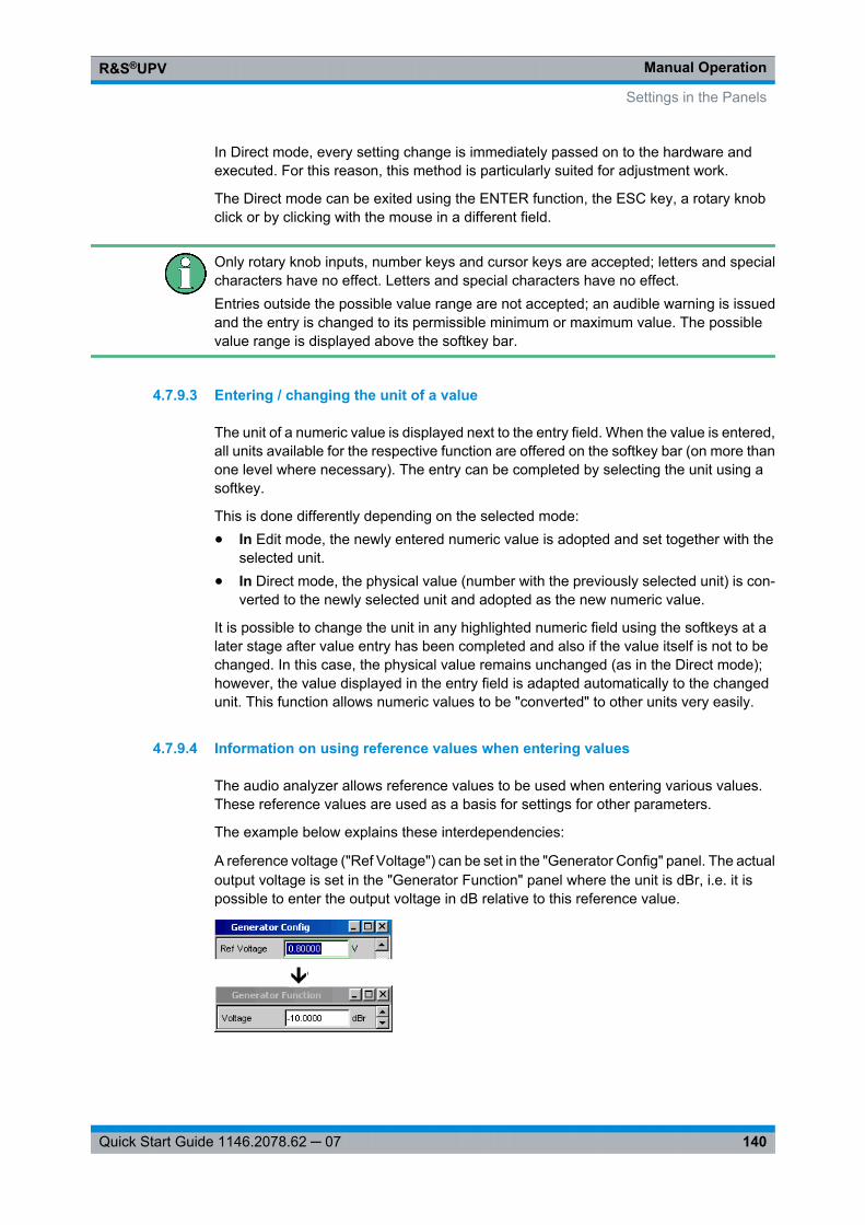
Manual OperationR&S®UPV
140Quick Start Guide 1146.2078.62 ─ 07
In Direct mode, every setting change is immediately passed on to the hardware andexecuted. For this reason, this method is particularly suited for adjustment work.
The Direct mode can be exited using the ENTER function, the ESC key, a rotary knobclick or by clicking with the mouse in a different field.
Only rotary knob inputs, number keys and cursor keys are accepted; letters and specialcharacters have no effect. Letters and special characters have no effect.Entries outside the possible value range are not accepted; an audible warning is issuedand the entry is changed to its permissible minimum or maximum value. The possiblevalue range is displayed above the softkey bar.
4.7.9.3 Entering / changing the unit of a value
The unit of a numeric value is displayed next to the entry field. When the value is entered,all units available for the respective function are offered on the softkey bar (on more thanone level where necessary). The entry can be completed by selecting the unit using asoftkey.
This is done differently depending on the selected mode:● In Edit mode, the newly entered numeric value is adopted and set together with the
selected unit.● In Direct mode, the physical value (number with the previously selected unit) is con-
verted to the newly selected unit and adopted as the new numeric value.
It is possible to change the unit in any highlighted numeric field using the softkeys at alater stage after value entry has been completed and also if the value itself is not to bechanged. In this case, the physical value remains unchanged (as in the Direct mode);however, the value displayed in the entry field is adapted automatically to the changedunit. This function allows numeric values to be "converted" to other units very easily.
4.7.9.4 Information on using reference values when entering values
The audio analyzer allows reference values to be used when entering various values.These reference values are used as a basis for settings for other parameters.
The example below explains these interdependencies:
A reference voltage ("Ref Voltage") can be set in the "Generator Config" panel. The actualoutput voltage is set in the "Generator Function" panel where the unit is dBr, i.e. it ispossible to enter the output voltage in dB relative to this reference value.
Settings in the Panels
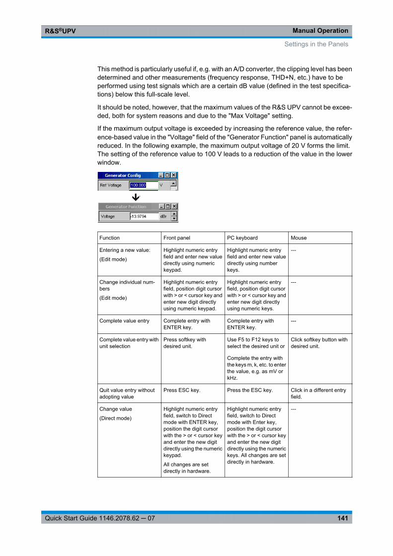
Manual OperationR&S®UPV
141Quick Start Guide 1146.2078.62 ─ 07
This method is particularly useful if, e.g. with an A/D converter, the clipping level has beendetermined and other measurements (frequency response, THD+N, etc.) have to beperformed using test signals which are a certain dB value (defined in the test specifica-tions) below this full-scale level.
It should be noted, however, that the maximum values of the R&S UPV cannot be excee-ded, both for system reasons and due to the "Max Voltage" setting.
If the maximum output voltage is exceeded by increasing the reference value, the refer-ence-based value in the "Voltage" field of the "Generator Function" panel is automaticallyreduced. In the following example, the maximum output voltage of 20 V forms the limit.The setting of the reference value to 100 V leads to a reduction of the value in the lowerwindow.
Function Front panel PC keyboard Mouse
Entering a new value:
(Edit mode)
Highlight numeric entryfield and enter new valuedirectly using numerickeypad.
Highlight numeric entryfield and enter new valuedirectly using numberkeys.
---
Change individual num-bers
(Edit mode)
Highlight numeric entryfield, position digit cursorwith > or < cursor key andenter new digit directlyusing numeric keypad.
Highlight numeric entryfield, position digit cursorwith > or < cursor key andenter new digit directlyusing numeric keys.
---
Complete value entry Complete entry withENTER key.
Complete entry withENTER key.
---
Complete value entry withunit selection
Press softkey withdesired unit.
Use F5 to F12 keys toselect the desired unit or
Complete the entry withthe keys m, k, etc. to enterthe value, e.g. as mV orkHz.
Click softkey button withdesired unit.
Quit value entry withoutadopting value
Press ESC key. Press the ESC key. Click in a different entryfield.
Change value
(Direct mode)
Highlight numeric entryfield, switch to Directmode with ENTER key,position the digit cursorwith the > or < cursor keyand enter the new digitdirectly using the numerickeypad.
All changes are setdirectly in hardware.
Highlight numeric entryfield, switch to Directmode with Enter key,position the digit cursorwith the > or < cursor keyand enter the new digitdirectly using the numerickeys. All changes are setdirectly in hardware.
---
Settings in the Panels
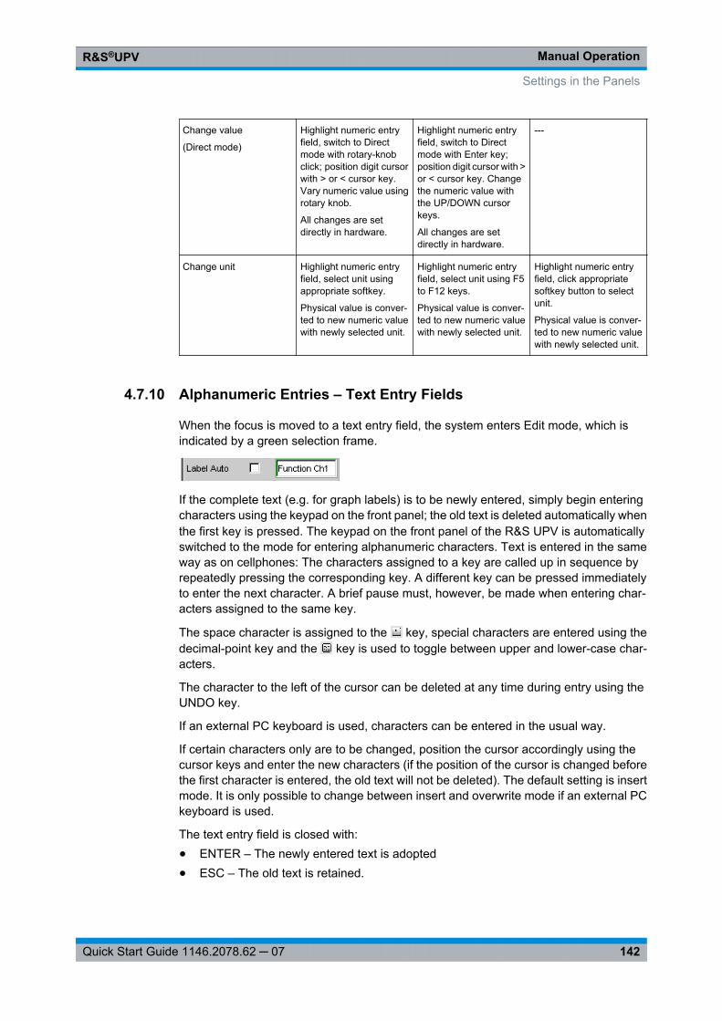
Manual OperationR&S®UPV
142Quick Start Guide 1146.2078.62 ─ 07
Change value
(Direct mode)
Highlight numeric entryfield, switch to Directmode with rotary-knobclick; position digit cursorwith > or < cursor key.Vary numeric value usingrotary knob.
All changes are setdirectly in hardware.
Highlight numeric entryfield, switch to Directmode with Enter key;position digit cursor with >or < cursor key. Changethe numeric value withthe UP/DOWN cursorkeys.
All changes are setdirectly in hardware.
---
Change unit Highlight numeric entryfield, select unit usingappropriate softkey.
Physical value is conver-ted to new numeric valuewith newly selected unit.
Highlight numeric entryfield, select unit using F5to F12 keys.
Physical value is conver-ted to new numeric valuewith newly selected unit.
Highlight numeric entryfield, click appropriatesoftkey button to selectunit.
Physical value is conver-ted to new numeric valuewith newly selected unit.
4.7.10 Alphanumeric Entries – Text Entry Fields
When the focus is moved to a text entry field, the system enters Edit mode, which isindicated by a green selection frame.
If the complete text (e.g. for graph labels) is to be newly entered, simply begin enteringcharacters using the keypad on the front panel; the old text is deleted automatically whenthe first key is pressed. The keypad on the front panel of the R&S UPV is automaticallyswitched to the mode for entering alphanumeric characters. Text is entered in the sameway as on cellphones: The characters assigned to a key are called up in sequence byrepeatedly pressing the corresponding key. A different key can be pressed immediatelyto enter the next character. A brief pause must, however, be made when entering char-acters assigned to the same key.
The space character is assigned to the key, special characters are entered using thedecimal-point key and the key is used to toggle between upper and lower-case char-acters.
The character to the left of the cursor can be deleted at any time during entry using theUNDO key.
If an external PC keyboard is used, characters can be entered in the usual way.
If certain characters only are to be changed, position the cursor accordingly using thecursor keys and enter the new characters (if the position of the cursor is changed beforethe first character is entered, the old text will not be deleted). The default setting is insertmode. It is only possible to change between insert and overwrite mode if an external PCkeyboard is used.
The text entry field is closed with:● ENTER – The newly entered text is adopted● ESC – The old text is retained.
Settings in the Panels
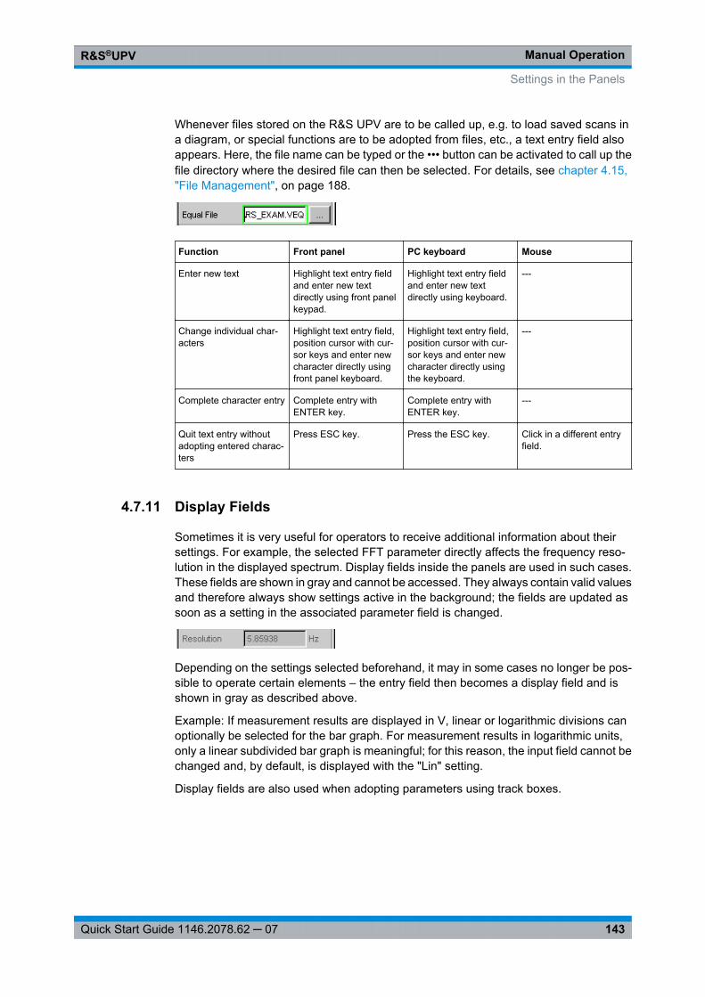
Manual OperationR&S®UPV
143Quick Start Guide 1146.2078.62 ─ 07
Whenever files stored on the R&S UPV are to be called up, e.g. to load saved scans ina diagram, or special functions are to be adopted from files, etc., a text entry field alsoappears. Here, the file name can be typed or the ••• button can be activated to call up thefile directory where the desired file can then be selected. For details, see chapter 4.15,"File Management", on page 188.
Function Front panel PC keyboard Mouse
Enter new text Highlight text entry fieldand enter new textdirectly using front panelkeypad.
Highlight text entry fieldand enter new textdirectly using keyboard.
---
Change individual char-acters
Highlight text entry field,position cursor with cur-sor keys and enter newcharacter directly usingfront panel keyboard.
Highlight text entry field,position cursor with cur-sor keys and enter newcharacter directly usingthe keyboard.
---
Complete character entry Complete entry withENTER key.
Complete entry withENTER key.
---
Quit text entry withoutadopting entered charac-ters
Press ESC key. Press the ESC key. Click in a different entryfield.
4.7.11 Display Fields
Sometimes it is very useful for operators to receive additional information about theirsettings. For example, the selected FFT parameter directly affects the frequency reso-lution in the displayed spectrum. Display fields inside the panels are used in such cases.These fields are shown in gray and cannot be accessed. They always contain valid valuesand therefore always show settings active in the background; the fields are updated assoon as a setting in the associated parameter field is changed.
Depending on the settings selected beforehand, it may in some cases no longer be pos-sible to operate certain elements – the entry field then becomes a display field and isshown in gray as described above.
Example: If measurement results are displayed in V, linear or logarithmic divisions canoptionally be selected for the bar graph. For measurement results in logarithmic units,only a linear subdivided bar graph is meaningful; for this reason, the input field cannot bechanged and, by default, is displayed with the "Lin" setting.
Display fields are also used when adopting parameters using track boxes.
Settings in the Panels
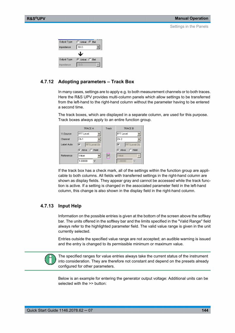
Manual OperationR&S®UPV
144Quick Start Guide 1146.2078.62 ─ 07
4.7.12 Adopting parameters – Track Box
In many cases, settings are to apply e.g. to both measurement channels or to both traces.Here the R&S UPV provides multi-column panels which allow settings to be transferredfrom the left-hand to the right-hand column without the parameter having to be entereda second time.
The track boxes, which are displayed in a separate column, are used for this purpose.Track boxes always apply to an entire function group.
If the track box has a check mark, all of the settings within the function group are appli-cable to both columns. All fields with transferred settings in the right-hand column areshown as display fields. They appear gray and cannot be accessed while the track func-tion is active. If a setting is changed in the associated parameter field in the left-handcolumn, this change is also shown in the display field in the right-hand column.
4.7.13 Input Help
Information on the possible entries is given at the bottom of the screen above the softkeybar. The units offered in the softkey bar and the limits specified in the "Valid Range" fieldalways refer to the highlighted parameter field. The valid value range is given in the unitcurrently selected.
Entries outside the specified value range are not accepted; an audible warning is issuedand the entry is changed to its permissible minimum or maximum value.
The specified ranges for value entries always take the current status of the instrumentinto consideration. They are therefore not constant and depend on the presets alreadyconfigured for other parameters.
Below is an example for entering the generator output voltage: Additional units can beselected with the >> button:
Settings in the Panels
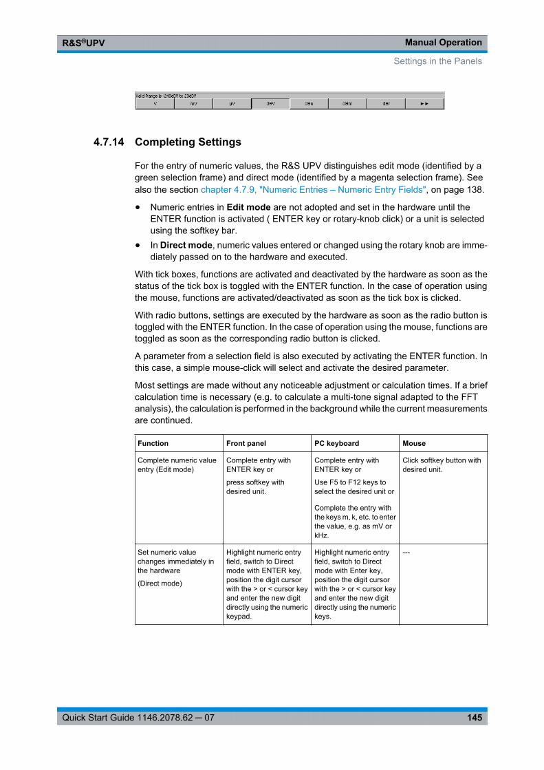
Manual OperationR&S®UPV
145Quick Start Guide 1146.2078.62 ─ 07
4.7.14 Completing Settings
For the entry of numeric values, the R&S UPV distinguishes edit mode (identified by agreen selection frame) and direct mode (identified by a magenta selection frame). Seealso the section chapter 4.7.9, "Numeric Entries – Numeric Entry Fields", on page 138.
● Numeric entries in Edit mode are not adopted and set in the hardware until theENTER function is activated ( ENTER key or rotary-knob click) or a unit is selectedusing the softkey bar.
● In Direct mode, numeric values entered or changed using the rotary knob are imme-diately passed on to the hardware and executed.
With tick boxes, functions are activated and deactivated by the hardware as soon as thestatus of the tick box is toggled with the ENTER function. In the case of operation usingthe mouse, functions are activated/deactivated as soon as the tick box is clicked.
With radio buttons, settings are executed by the hardware as soon as the radio button istoggled with the ENTER function. In the case of operation using the mouse, functions aretoggled as soon as the corresponding radio button is clicked.
A parameter from a selection field is also executed by activating the ENTER function. Inthis case, a simple mouse-click will select and activate the desired parameter.
Most settings are made without any noticeable adjustment or calculation times. If a briefcalculation time is necessary (e.g. to calculate a multi-tone signal adapted to the FFTanalysis), the calculation is performed in the background while the current measurementsare continued.
Function Front panel PC keyboard Mouse
Complete numeric valueentry (Edit mode)
Complete entry withENTER key or
press softkey withdesired unit.
Complete entry withENTER key or
Use F5 to F12 keys toselect the desired unit or
Complete the entry withthe keys m, k, etc. to enterthe value, e.g. as mV orkHz.
Click softkey button withdesired unit.
Set numeric valuechanges immediately inthe hardware
(Direct mode)
Highlight numeric entryfield, switch to Directmode with ENTER key,position the digit cursorwith the > or < cursor keyand enter the new digitdirectly using the numerickeypad.
Highlight numeric entryfield, switch to Directmode with Enter key,position the digit cursorwith the > or < cursor keyand enter the new digitdirectly using the numerickeys.
---
Settings in the Panels
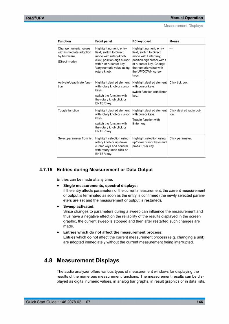
Manual OperationR&S®UPV
146Quick Start Guide 1146.2078.62 ─ 07
Function Front panel PC keyboard Mouse
Change numeric valueswith immediate adoptionby hardware
(Direct mode)
Highlight numeric entryfield, switch to Directmode with rotary-knobclick; position digit cursorwith > or < cursor key.Vary numeric value usingrotary knob.
Highlight numeric entryfield, switch to Directmode with Enter key;position digit cursor with >or < cursor key. Changethe numeric value withthe UP/DOWN cursorkeys.
---
Activate/deactivate func-tion
Highlight desired elementwith rotary knob or cursorkeys,
switch the function withthe rotary knob click orENTER key.
Highlight desired elementwith cursor keys,
switch function with Enterkey.
Click tick box.
Toggle function Highlight desired elementwith rotary knob or cursorkeys,
switch the function withthe rotary knob click orENTER key.
Highlight desired elementwith cursor keys,
Toggle function withEnter key.
Click desired radio but-ton.
Select parameter from list Highlight selection usingrotary knob or up/downcursor keys and confirmwith rotary-knob click orENTER key.
Highlight selection usingup/down cursor keys andpress Enter key.
Click parameter.
4.7.15 Entries during Measurement or Data Output
Entries can be made at any time.● Single measurements, spectral displays:
If the entry affects parameters of the current measurement, the current measurementor output is terminated as soon as the entry is confirmed (the newly selected param-eters are set and the measurement or output is restarted).
● Sweep activated:Since changes to parameters during a sweep can influence the measurement andthus have a negative effect on the reliability of the results displayed in the screengraphic, the current sweep is stopped and then after restarted such changes aremade.
● Entries which do not affect the measurement process:Entries which do not affect the current measurement process (e.g. changing a unit)are adopted immediately without the current measurement being interrupted.
4.8 Measurement Displays
The audio analyzer offers various types of measurement windows for displaying theresults of the numerous measurement functions. The measurement results can be dis-played as digital numeric values, in analog bar graphs, in result graphics or in data lists.
Measurement Displays
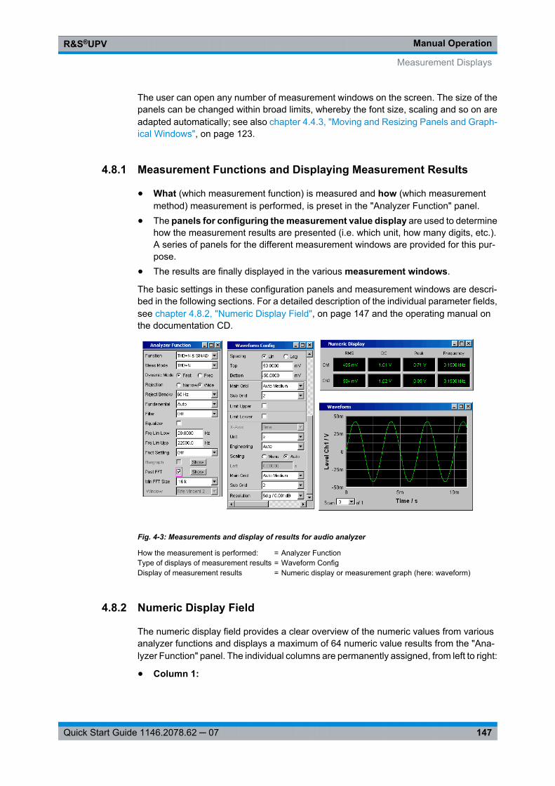
Manual OperationR&S®UPV
147Quick Start Guide 1146.2078.62 ─ 07
The user can open any number of measurement windows on the screen. The size of thepanels can be changed within broad limits, whereby the font size, scaling and so on areadapted automatically; see also chapter 4.4.3, "Moving and Resizing Panels and Graph-ical Windows", on page 123.
4.8.1 Measurement Functions and Displaying Measurement Results
● What (which measurement function) is measured and how (which measurementmethod) measurement is performed, is preset in the "Analyzer Function" panel.
● The panels for configuring the measurement value display are used to determinehow the measurement results are presented (i.e. which unit, how many digits, etc.).A series of panels for the different measurement windows are provided for this pur-pose.
● The results are finally displayed in the various measurement windows.
The basic settings in these configuration panels and measurement windows are descri-bed in the following sections. For a detailed description of the individual parameter fields,see chapter 4.8.2, "Numeric Display Field", on page 147 and the operating manual onthe documentation CD.
Fig. 4-3: Measurements and display of results for audio analyzer
How the measurement is performed: = Analyzer FunctionType of displays of measurement results = Waveform ConfigDisplay of measurement results = Numeric display or measurement graph (here: waveform)
4.8.2 Numeric Display Field
The numeric display field provides a clear overview of the numeric values from variousanalyzer functions and displays a maximum of 64 numeric value results from the "Ana-lyzer Function" panel. The individual columns are permanently assigned, from left to right:
● Column 1:
Measurement Displays
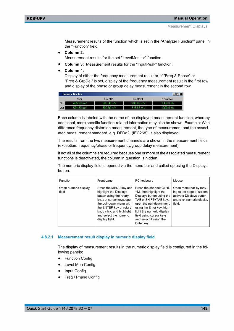
Manual OperationR&S®UPV
148Quick Start Guide 1146.2078.62 ─ 07
Measurement results of the function which is set in the "Analyzer Function" panel inthe "Function" field.
● Column 2:Measurement results for the set "LevelMonitor" function.
● Column 3: Measurement results for the "InputPeak" function.● Column 4:
Display of either the frequency measurement result or, if "Freq & Phase" or"Freq & GrpDel" is set, display of the frequency measurement result in the first rowand display of the phase or group delay measurement in the second row.
Each column is labeled with the name of the displayed measurement function, wherebyadditional, more specific function-related information may also be shown. Example: Withdifference frequency distortion measurement, the type of measurement and the associ-ated measurement standard, e.g. DFDd2 (IEC268), is also displayed.
The results from the two measurement channels are shown in the measurement fields(exception: frequency/phase or frequency/group delay measurement).
If not all of the columns are required because one or more of the associated measurementfunctions is deactivated, the column in question is hidden.
The numeric display field is opened via the menu bar and called up using the Displaysbutton.
Function Front panel PC keyboard Mouse
Open numeric displayfield
Press the MENU key andhighlight the Displaysbutton using the rotaryknob or cursor keys, openthe pull-down menu withthe ENTER key or rotary-knob click, and highlightand select the numericdisplay field.
Press the shortcut CTRL+M, then highlight theDisplays button using theTAB or SHIFT+TAB keys,open the pull-down menuusing the Enter key, high-light the numeric displayfield using cursor keysand select it using theEnter key.
Open menu bar by mov-ing to left edge of screen,activate Displays buttonand click numeric displayfield.
4.8.2.1 Measurement result display in numeric display field
The display of measurement results in the numeric display field is configured in the fol-lowing panels:● Function Config● Level Mon Config● Input Config● Freq / Phase Config
Measurement Displays
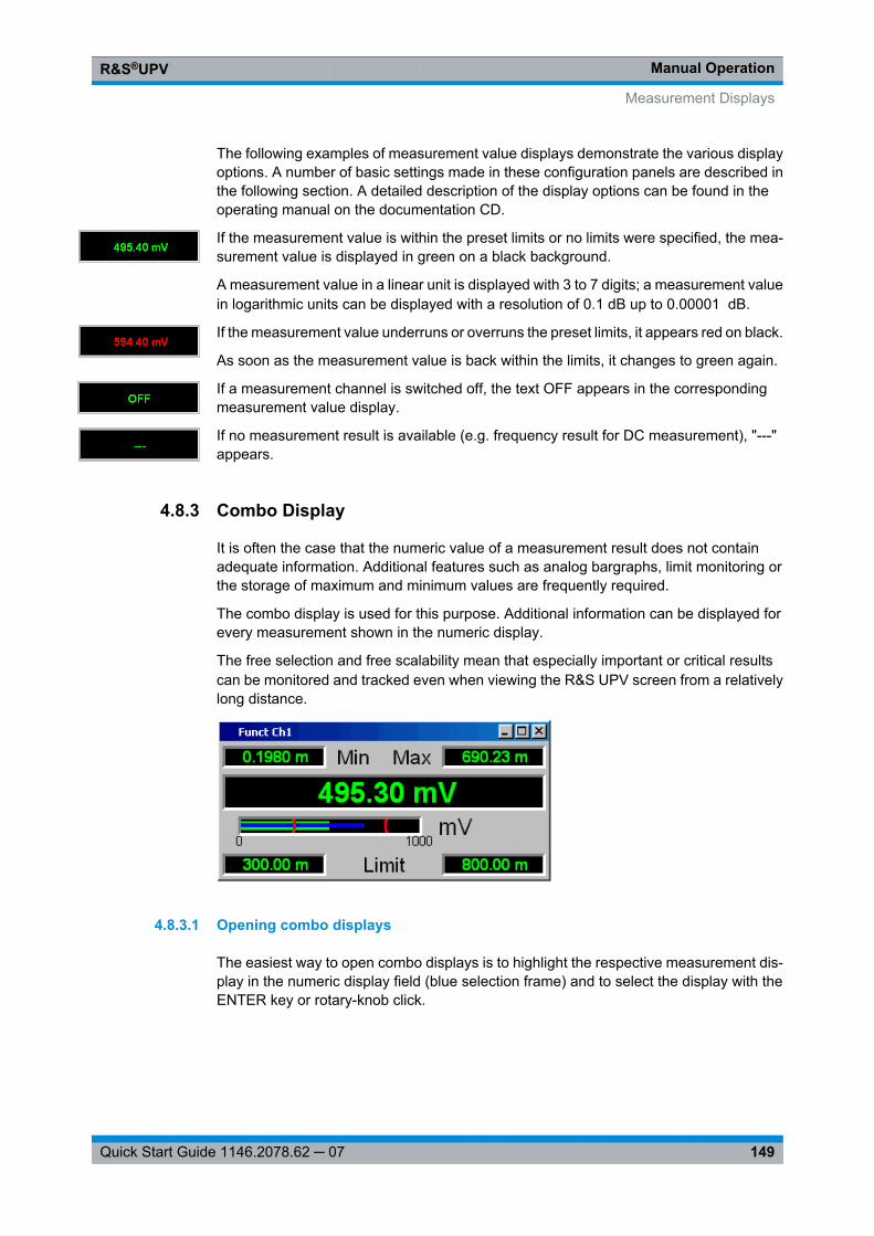
Manual OperationR&S®UPV
149Quick Start Guide 1146.2078.62 ─ 07
The following examples of measurement value displays demonstrate the various displayoptions. A number of basic settings made in these configuration panels are described inthe following section. A detailed description of the display options can be found in theoperating manual on the documentation CD.
If the measurement value is within the preset limits or no limits were specified, the mea-surement value is displayed in green on a black background.
A measurement value in a linear unit is displayed with 3 to 7 digits; a measurement valuein logarithmic units can be displayed with a resolution of 0.1 dB up to 0.00001 dB.
If the measurement value underruns or overruns the preset limits, it appears red on black.
As soon as the measurement value is back within the limits, it changes to green again.
If a measurement channel is switched off, the text OFF appears in the correspondingmeasurement value display.
If no measurement result is available (e.g. frequency result for DC measurement), "---"appears.
4.8.3 Combo Display
It is often the case that the numeric value of a measurement result does not containadequate information. Additional features such as analog bargraphs, limit monitoring orthe storage of maximum and minimum values are frequently required.
The combo display is used for this purpose. Additional information can be displayed forevery measurement shown in the numeric display.
The free selection and free scalability mean that especially important or critical resultscan be monitored and tracked even when viewing the R&S UPV screen from a relativelylong distance.
4.8.3.1 Opening combo displays
The easiest way to open combo displays is to highlight the respective measurement dis-play in the numeric display field (blue selection frame) and to select the display with theENTER key or rotary-knob click.
Measurement Displays
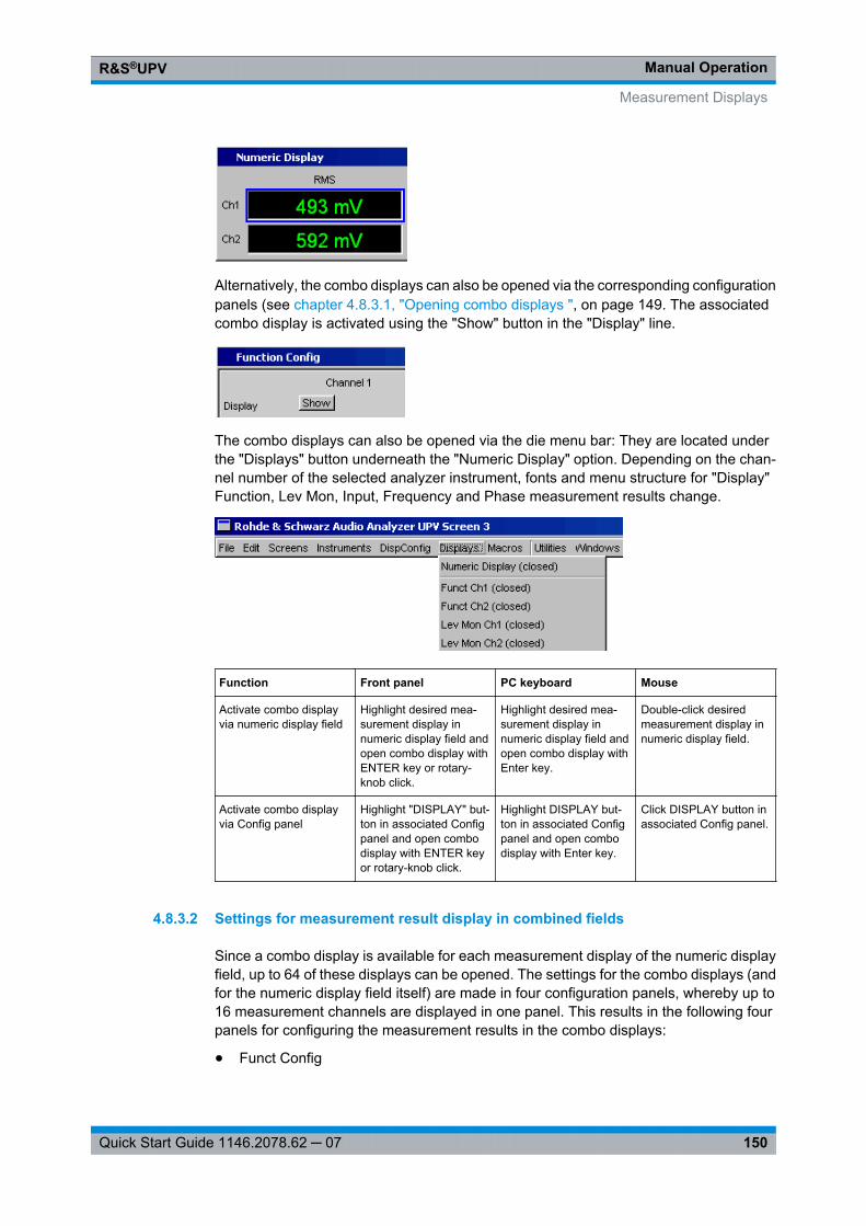
Manual OperationR&S®UPV
150Quick Start Guide 1146.2078.62 ─ 07
Alternatively, the combo displays can also be opened via the corresponding configurationpanels (see chapter 4.8.3.1, "Opening combo displays ", on page 149. The associatedcombo display is activated using the "Show" button in the "Display" line.
The combo displays can also be opened via the die menu bar: They are located underthe "Displays" button underneath the "Numeric Display" option. Depending on the chan-nel number of the selected analyzer instrument, fonts and menu structure for "Display"Function, Lev Mon, Input, Frequency and Phase measurement results change.
Function Front panel PC keyboard Mouse
Activate combo displayvia numeric display field
Highlight desired mea-surement display innumeric display field andopen combo display withENTER key or rotary-knob click.
Highlight desired mea-surement display innumeric display field andopen combo display withEnter key.
Double-click desiredmeasurement display innumeric display field.
Activate combo displayvia Config panel
Highlight "DISPLAY" but-ton in associated Configpanel and open combodisplay with ENTER keyor rotary-knob click.
Highlight DISPLAY but-ton in associated Configpanel and open combodisplay with Enter key.
Click DISPLAY button inassociated Config panel.
4.8.3.2 Settings for measurement result display in combined fields
Since a combo display is available for each measurement display of the numeric displayfield, up to 64 of these displays can be opened. The settings for the combo displays (andfor the numeric display field itself) are made in four configuration panels, whereby up to16 measurement channels are displayed in one panel. This results in the following fourpanels for configuring the measurement results in the combo displays:
● Funct Config
Measurement Displays
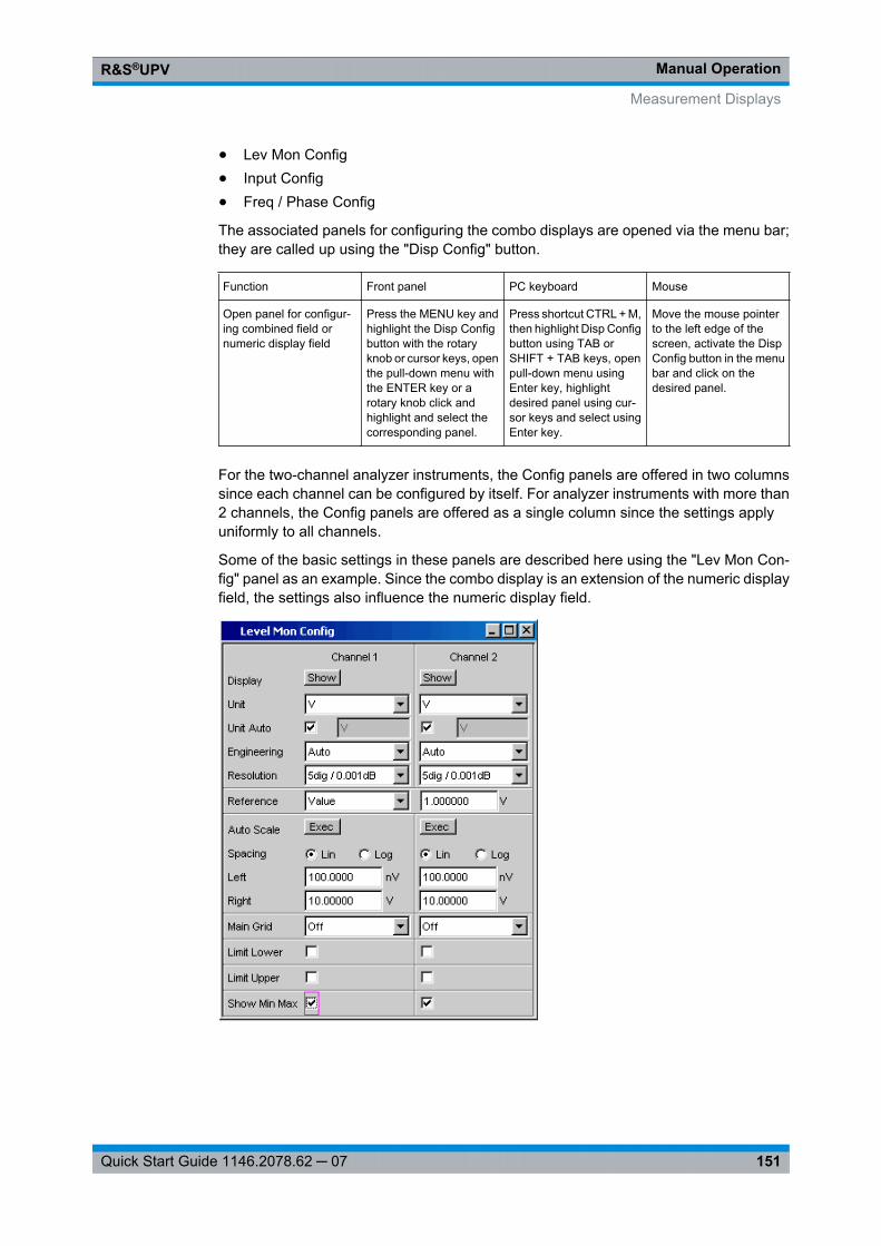
Manual OperationR&S®UPV
151Quick Start Guide 1146.2078.62 ─ 07
● Lev Mon Config● Input Config● Freq / Phase Config
The associated panels for configuring the combo displays are opened via the menu bar;they are called up using the "Disp Config" button.
Function Front panel PC keyboard Mouse
Open panel for configur-ing combined field ornumeric display field
Press the MENU key andhighlight the Disp Configbutton with the rotaryknob or cursor keys, openthe pull-down menu withthe ENTER key or arotary knob click andhighlight and select thecorresponding panel.
Press shortcut CTRL + M,then highlight Disp Configbutton using TAB orSHIFT + TAB keys, openpull-down menu usingEnter key, highlightdesired panel using cur-sor keys and select usingEnter key.
Move the mouse pointerto the left edge of thescreen, activate the DispConfig button in the menubar and click on thedesired panel.
For the two-channel analyzer instruments, the Config panels are offered in two columnssince each channel can be configured by itself. For analyzer instruments with more than2 channels, the Config panels are offered as a single column since the settings applyuniformly to all channels.
Some of the basic settings in these panels are described here using the "Lev Mon Con-fig" panel as an example. Since the combo display is an extension of the numeric displayfield, the settings also influence the numeric display field.
Measurement Displays
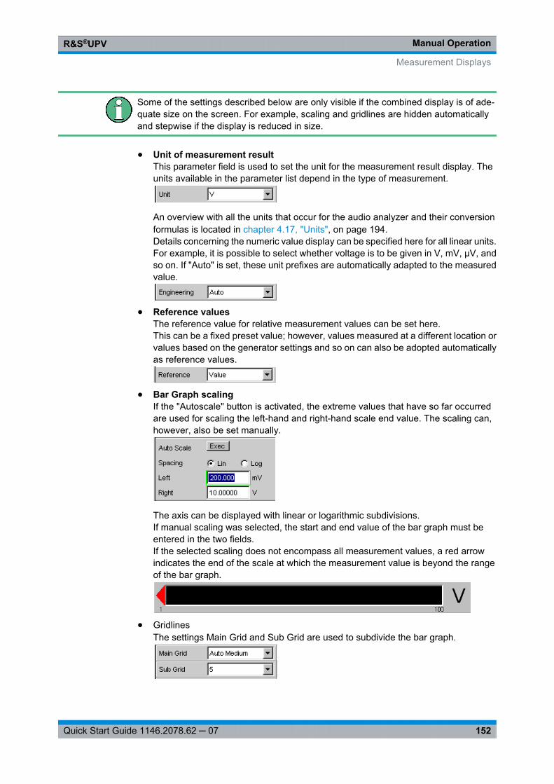
Manual OperationR&S®UPV
152Quick Start Guide 1146.2078.62 ─ 07
Some of the settings described below are only visible if the combined display is of ade-quate size on the screen. For example, scaling and gridlines are hidden automaticallyand stepwise if the display is reduced in size.
● Unit of measurement resultThis parameter field is used to set the unit for the measurement result display. Theunits available in the parameter list depend in the type of measurement.
An overview with all the units that occur for the audio analyzer and their conversionformulas is located in chapter 4.17, "Units", on page 194.Details concerning the numeric value display can be specified here for all linear units.For example, it is possible to select whether voltage is to be given in V, mV, µV, andso on. If "Auto" is set, these unit prefixes are automatically adapted to the measuredvalue.
● Reference valuesThe reference value for relative measurement values can be set here.This can be a fixed preset value; however, values measured at a different location orvalues based on the generator settings and so on can also be adopted automaticallyas reference values.
● Bar Graph scalingIf the "Autoscale" button is activated, the extreme values that have so far occurredare used for scaling the left-hand and right-hand scale end value. The scaling can,however, also be set manually.
The axis can be displayed with linear or logarithmic subdivisions.If manual scaling was selected, the start and end value of the bar graph must beentered in the two fields.If the selected scaling does not encompass all measurement values, a red arrowindicates the end of the scale at which the measurement value is beyond the rangeof the bar graph.
● GridlinesThe settings Main Grid and Sub Grid are used to subdivide the bar graph.
Measurement Displays
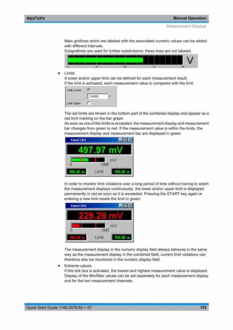
Manual OperationR&S®UPV
153Quick Start Guide 1146.2078.62 ─ 07
Main gridlines which are labeled with the associated numeric values can be addedwith different intervals.Subgridlines are used for further subdivisions; these lines are not labeled.
● LimitsA lower and/or upper limit can be defined for each measurement result.If the limit is activated, each measurement value is compared with the limit.
The set limits are shown in the bottom part of the combined display and appear as ared limit marking on the bar graph.As soon as one of the limits is exceeded, the measurement display and measurementbar changes from green to red. If the measurement value is within the limits, themeasurement display and measurement bar are displayed in green.
In order to monitor limit violations over a long period of time without having to watchthe measurement displays continuously, the lower and/or upper limit is displayedpermanently in red as soon as it is exceeded. Pressing the START key again orentering a new limit resets the limit to green.
The measurement display in the numeric display field always behaves in the sameway as the measurement display in the combined field; current limit violations cantherefore also be monitored in the numeric display field.
● Extreme valuesIf this tick box is activated, the lowest and highest measurement value is displayed.Display of the Min/Max values can be set separately for each measurement displayand for the two measurement channels.
Measurement Displays
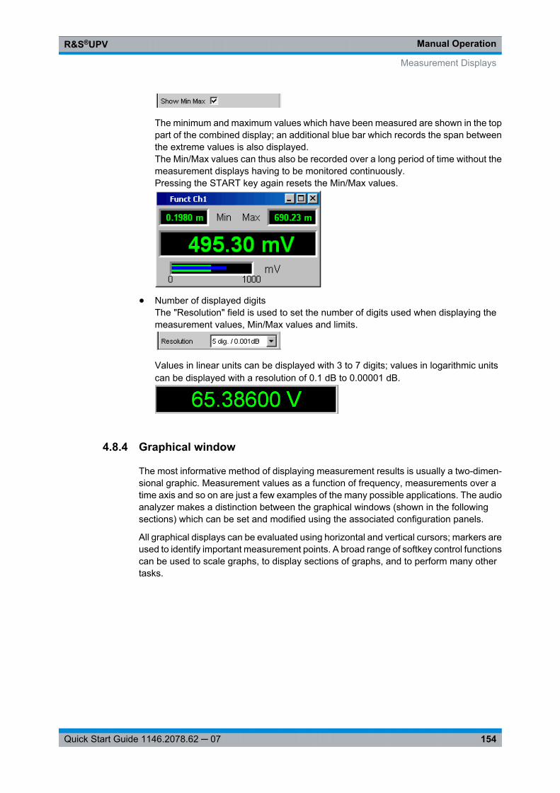
Manual OperationR&S®UPV
154Quick Start Guide 1146.2078.62 ─ 07
The minimum and maximum values which have been measured are shown in the toppart of the combined display; an additional blue bar which records the span betweenthe extreme values is also displayed.The Min/Max values can thus also be recorded over a long period of time without themeasurement displays having to be monitored continuously.Pressing the START key again resets the Min/Max values.
● Number of displayed digitsThe "Resolution" field is used to set the number of digits used when displaying themeasurement values, Min/Max values and limits.
Values in linear units can be displayed with 3 to 7 digits; values in logarithmic unitscan be displayed with a resolution of 0.1 dB to 0.00001 dB.
4.8.4 Graphical window
The most informative method of displaying measurement results is usually a two-dimen-sional graphic. Measurement values as a function of frequency, measurements over atime axis and so on are just a few examples of the many possible applications. The audioanalyzer makes a distinction between the graphical windows (shown in the followingsections) which can be set and modified using the associated configuration panels.
All graphical displays can be evaluated using horizontal and vertical cursors; markers areused to identify important measurement points. A broad range of softkey control functionscan be used to scale graphs, to display sections of graphs, and to perform many othertasks.
Measurement Displays
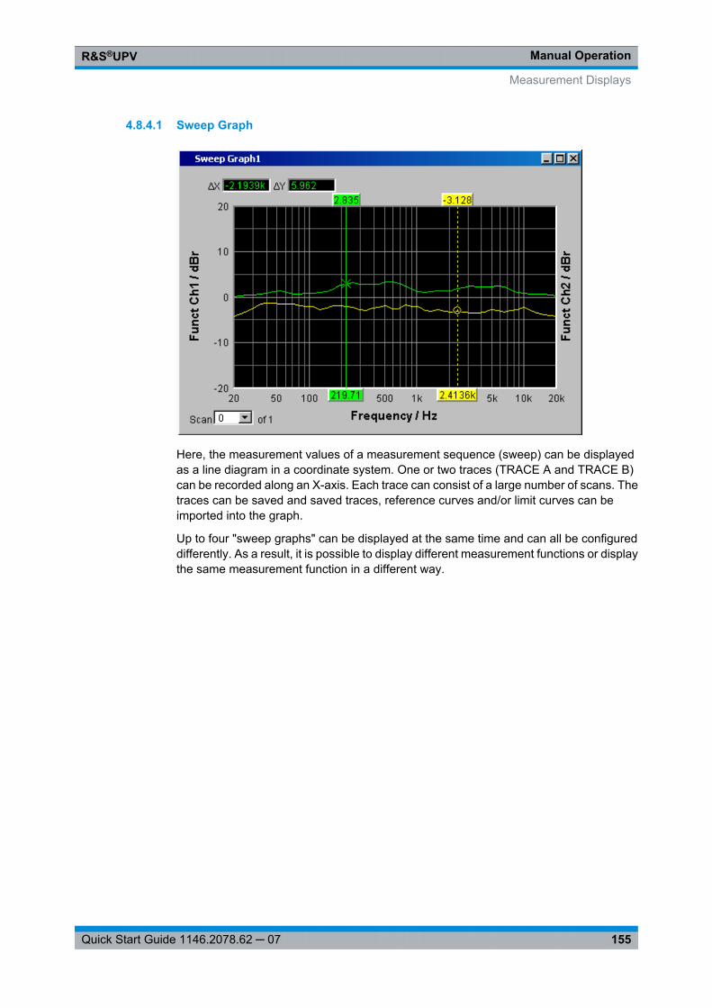
Manual OperationR&S®UPV
155Quick Start Guide 1146.2078.62 ─ 07
4.8.4.1 Sweep Graph
Here, the measurement values of a measurement sequence (sweep) can be displayedas a line diagram in a coordinate system. One or two traces (TRACE A and TRACE B)can be recorded along an X-axis. Each trace can consist of a large number of scans. Thetraces can be saved and saved traces, reference curves and/or limit curves can beimported into the graph.
Up to four "sweep graphs" can be displayed at the same time and can all be configureddifferently. As a result, it is possible to display different measurement functions or displaythe same measurement function in a different way.
Measurement Displays
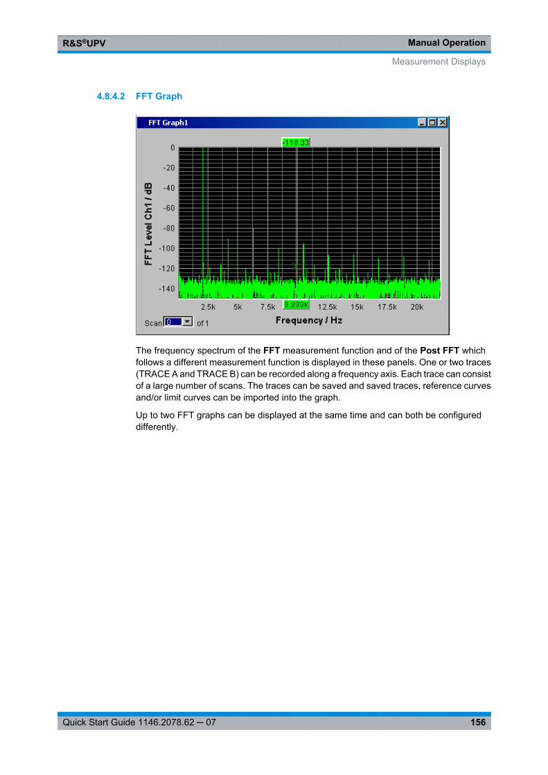
Manual OperationR&S®UPV
156Quick Start Guide 1146.2078.62 ─ 07
4.8.4.2 FFT Graph
The frequency spectrum of the FFT measurement function and of the Post FFT whichfollows a different measurement function is displayed in these panels. One or two traces(TRACE A and TRACE B) can be recorded along a frequency axis. Each trace can consistof a large number of scans. The traces can be saved and saved traces, reference curvesand/or limit curves can be imported into the graph.
Up to two FFT graphs can be displayed at the same time and can both be configureddifferently.
Measurement Displays
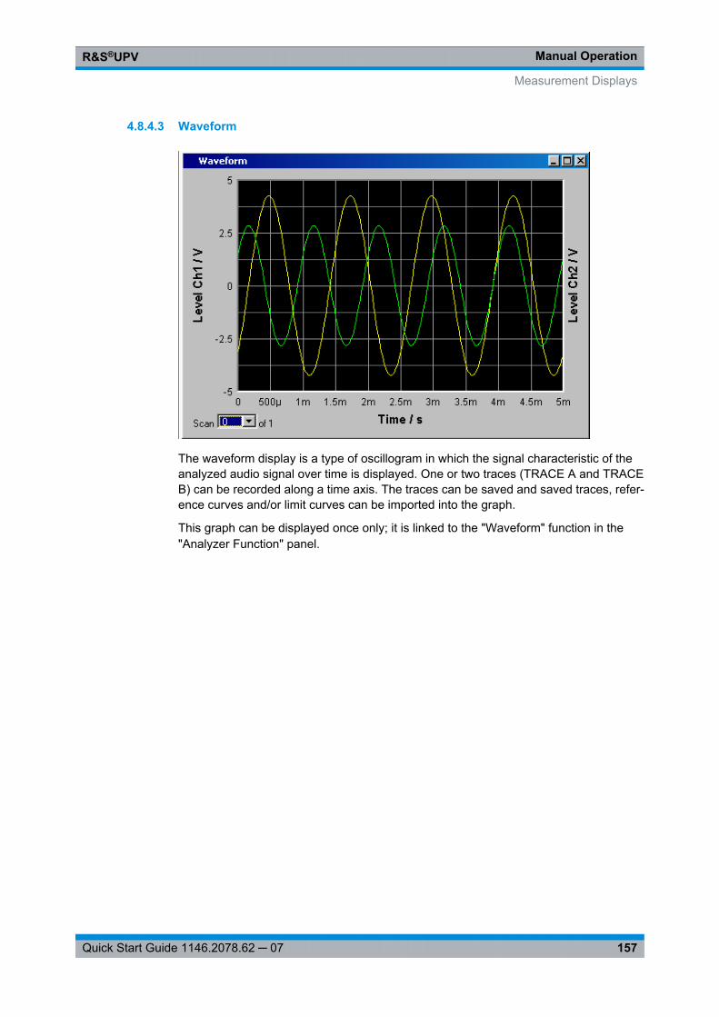
Manual OperationR&S®UPV
157Quick Start Guide 1146.2078.62 ─ 07
4.8.4.3 Waveform
The waveform display is a type of oscillogram in which the signal characteristic of theanalyzed audio signal over time is displayed. One or two traces (TRACE A and TRACEB) can be recorded along a time axis. The traces can be saved and saved traces, refer-ence curves and/or limit curves can be imported into the graph.
This graph can be displayed once only; it is linked to the "Waveform" function in the"Analyzer Function" panel.
Measurement Displays
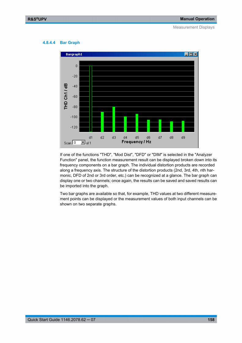
Manual OperationR&S®UPV
158Quick Start Guide 1146.2078.62 ─ 07
4.8.4.4 Bar Graph
If one of the functions "THD", "Mod Dist", "DFD" or "DIM" is selected in the "AnalyzerFunction" panel, the function measurement result can be displayed broken down into itsfrequency components on a bar graph. The individual distortion products are recordedalong a frequency axis. The structure of the distortion products (2nd, 3rd, 4th, nth har-monic, DFD of 2nd or 3rd order, etc.) can be recognized at a glance. The bar graph candisplay one or two channels; once again, the results can be saved and saved results canbe imported into the graph.
Two bar graphs are available so that, for example, THD values at two different measure-ment points can be displayed or the measurement values of both input channels can beshown on two separate graphs.
Measurement Displays
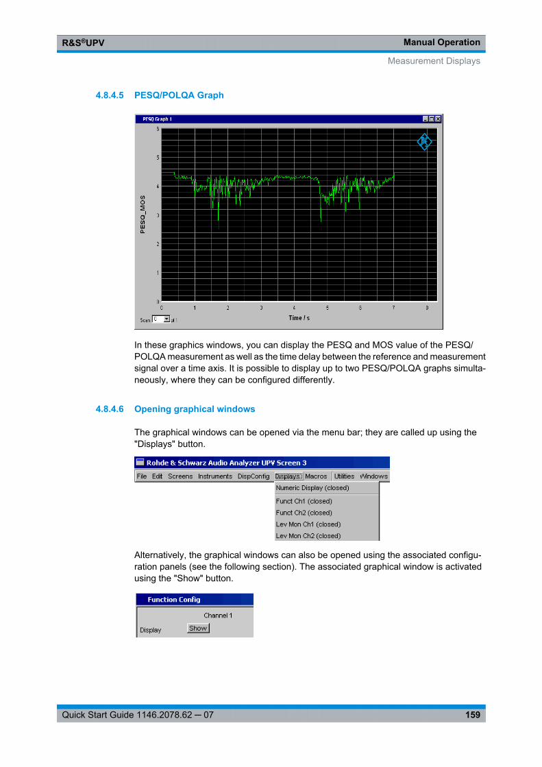
Manual OperationR&S®UPV
159Quick Start Guide 1146.2078.62 ─ 07
4.8.4.5 PESQ/POLQA Graph
In these graphics windows, you can display the PESQ and MOS value of the PESQ/POLQA measurement as well as the time delay between the reference and measurementsignal over a time axis. It is possible to display up to two PESQ/POLQA graphs simulta-neously, where they can be configured differently.
4.8.4.6 Opening graphical windows
The graphical windows can be opened via the menu bar; they are called up using the"Displays" button.
Alternatively, the graphical windows can also be opened using the associated configu-ration panels (see the following section). The associated graphical window is activatedusing the "Show" button.
Measurement Displays
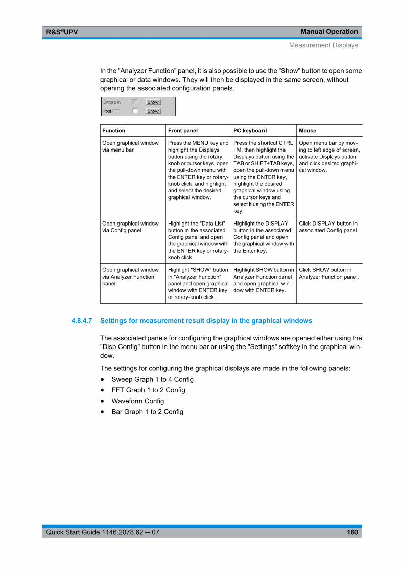
Manual OperationR&S®UPV
160Quick Start Guide 1146.2078.62 ─ 07
In the "Analyzer Function" panel, it is also possible to use the "Show" button to open somegraphical or data windows. They will then be displayed in the same screen, withoutopening the associated configuration panels.
Function Front panel PC keyboard Mouse
Open graphical windowvia menu bar
Press the MENU key andhighlight the Displaysbutton using the rotaryknob or cursor keys, openthe pull-down menu withthe ENTER key or rotary-knob click, and highlightand select the desiredgraphical window.
Press the shortcut CTRL+M, then highlight theDisplays button using theTAB or SHIFT+TAB keys,open the pull-down menuusing the ENTER key,highlight the desiredgraphical window usingthe cursor keys andselect it using the ENTERkey.
Open menu bar by mov-ing to left edge of screen,activate Displays buttonand click desired graphi-cal window.
Open graphical windowvia Config panel
Highlight the "Data List"button in the associatedConfig panel and openthe graphical window withthe ENTER key or rotary-knob click.
Highlight the DISPLAYbutton in the associatedConfig panel and openthe graphical window withthe Enter key.
Click DISPLAY button inassociated Config panel.
Open graphical windowvia Analyzer Functionpanel
Highlight "SHOW" buttonin "Analyzer Function"panel and open graphicalwindow with ENTER keyor rotary-knob click.
Highlight SHOW button inAnalyzer Function paneland open graphical win-dow with ENTER key.
Click SHOW button inAnalyzer Function panel.
4.8.4.7 Settings for measurement result display in the graphical windows
The associated panels for configuring the graphical windows are opened either using the"Disp Config" button in the menu bar or using the "Settings" softkey in the graphical win-dow.
The settings for configuring the graphical displays are made in the following panels:● Sweep Graph 1 to 4 Config● FFT Graph 1 to 2 Config● Waveform Config● Bar Graph 1 to 2 Config
Measurement Displays
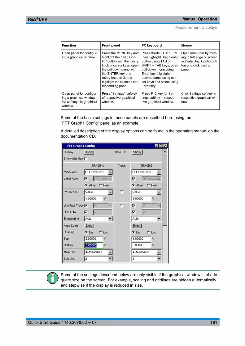
Manual OperationR&S®UPV
161Quick Start Guide 1146.2078.62 ─ 07
Function Front panel PC keyboard Mouse
Open panel for configur-ing a graphical window
Press the MENU key andhighlight the "Disp Con-fig" button with the rotaryknob or cursor keys, openthe pulldown menu withthe ENTER key or arotary knob click andhighlight the selected cor-responding panel.
Press shortcut CTRL + M,then highlight Disp Configbutton using TAB orSHIFT + TAB keys, openpull-down menu usingEnter key, highlightdesired panel using cur-sor keys and select usingEnter key.
Open menu bar by mov-ing to left edge of screen,activate Disp Config but-ton and click desiredpanel.
Open panel for configur-ing a graphical windowvia softkeys in graphicalwindow
Press "Settings" softkeyof respective graphicalwindow.
Press F12 key for Set-tings softkey in respec-tive graphical window.
Click Settings softkey inrespective graphical win-dow.
Some of the basic settings in these panels are described here using the"FFT Graph1 Config" panel as an example.
A detailed description of the display options can be found in the operating manual on thedocumentation CD.
Some of the settings described below are only visible if the graphical window is of ade-quate size on the screen. For example, scaling and gridlines are hidden automaticallyand stepwise if the display is reduced in size.
Measurement Displays
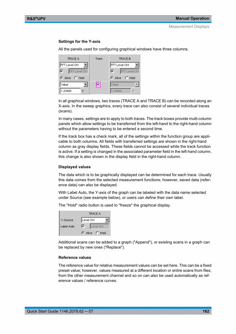
Manual OperationR&S®UPV
162Quick Start Guide 1146.2078.62 ─ 07
Settings for the Y-axis
All the panels used for configuring graphical windows have three columns.
In all graphical windows, two traces (TRACE A and TRACE B) can be recorded along anX-axis. In the sweep graphics, every trace can also consist of several individual traces(scans).
In many cases, settings are to apply to both traces. The track boxes provide multi-columnpanels which allow settings to be transferred from the left-hand to the right-hand columnwithout the parameters having to be entered a second time.
If the track box has a check mark, all of the settings within the function group are appli-cable to both columns. All fields with transferred settings are shown in the right-handcolumn as gray display fields. These fields cannot be accessed while the track functionis active. If a setting is changed in the associated parameter field in the left-hand column,this change is also shown in the display field in the right-hand column.
Displayed values
The data which is to be graphically displayed can be determined for each trace. Usuallythis data comes from the selected measurement functions; however, saved data (refer-ence data) can also be displayed.
With Label Auto, the Y-axis of the graph can be labeled with the data name selectedunder Source (see example below), or users can define their own label.
The "Hold" radio button is used to "freeze" the graphical display.
Additional scans can be added to a graph ("Append"), or existing scans in a graph canbe replaced by new ones ("Replace").
Reference values
The reference value for relative measurement values can be set here. This can be a fixedpreset value; however, values measured at a different location or entire scans from files,from the other measurement channel and so on can also be used automatically as ref-erence values / reference curves.
Measurement Displays
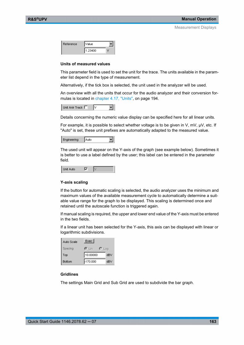
Manual OperationR&S®UPV
163Quick Start Guide 1146.2078.62 ─ 07
Units of measured values
This parameter field is used to set the unit for the trace. The units available in the param-eter list depend in the type of measurement.
Alternatively, if the tick box is selected, the unit used in the analyzer will be used.
An overview with all the units that occur for the audio analyzer and their conversion for-mulas is located in chapter 4.17, "Units", on page 194.
Details concerning the numeric value display can be specified here for all linear units.
For example, it is possible to select whether voltage is to be given in V, mV, µV, etc. If"Auto" is set, these unit prefixes are automatically adapted to the measured value.
The used unit will appear on the Y-axis of the graph (see example below). Sometimes itis better to use a label defined by the user; this label can be entered in the parameterfield.
Y-axis scaling
If the button for automatic scaling is selected, the audio analyzer uses the minimum andmaximum values of the available measurement cycle to automatically determine a suit-able value range for the graph to be displayed. This scaling is determined once andretained until the autoscale function is triggered again.
If manual scaling is required, the upper and lower end value of the Y-axis must be enteredin the two fields.
If a linear unit has been selected for the Y-axis, this axis can be displayed with linear orlogarithmic subdivisions.
Gridlines
The settings Main Grid and Sub Grid are used to subdivide the bar graph.
Measurement Displays
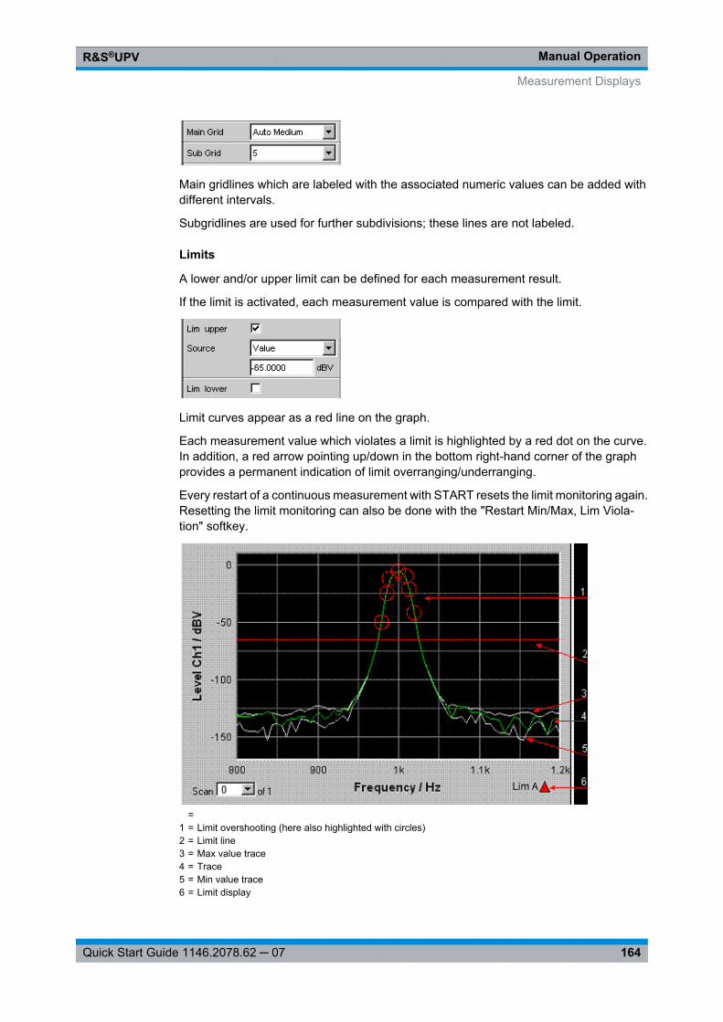
Manual OperationR&S®UPV
164Quick Start Guide 1146.2078.62 ─ 07
Main gridlines which are labeled with the associated numeric values can be added withdifferent intervals.
Subgridlines are used for further subdivisions; these lines are not labeled.
Limits
A lower and/or upper limit can be defined for each measurement result.
If the limit is activated, each measurement value is compared with the limit.
Limit curves appear as a red line on the graph.
Each measurement value which violates a limit is highlighted by a red dot on the curve.In addition, a red arrow pointing up/down in the bottom right-hand corner of the graphprovides a permanent indication of limit overranging/underranging.
Every restart of a continuous measurement with START resets the limit monitoring again.Resetting the limit monitoring can also be done with the "Restart Min/Max, Lim Viola-tion" softkey.
=1 = Limit overshooting (here also highlighted with circles)2 = Limit line3 = Max value trace4 = Trace5 = Min value trace6 = Limit display
Measurement Displays
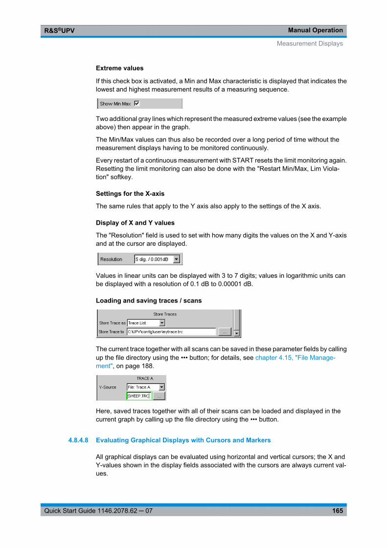
Manual OperationR&S®UPV
165Quick Start Guide 1146.2078.62 ─ 07
Extreme values
If this check box is activated, a Min and Max characteristic is displayed that indicates thelowest and highest measurement results of a measuring sequence.
Two additional gray lines which represent the measured extreme values (see the exampleabove) then appear in the graph.
The Min/Max values can thus also be recorded over a long period of time without themeasurement displays having to be monitored continuously.
Every restart of a continuous measurement with START resets the limit monitoring again.Resetting the limit monitoring can also be done with the "Restart Min/Max, Lim Viola-tion" softkey.
Settings for the X-axis
The same rules that apply to the Y axis also apply to the settings of the X axis.
Display of X and Y values
The "Resolution" field is used to set with how many digits the values on the X and Y-axisand at the cursor are displayed.
Values in linear units can be displayed with 3 to 7 digits; values in logarithmic units canbe displayed with a resolution of 0.1 dB to 0.00001 dB.
Loading and saving traces / scans
The current trace together with all scans can be saved in these parameter fields by callingup the file directory using the ••• button; for details, see chapter 4.15, "File Manage-ment", on page 188.
Here, saved traces together with all of their scans can be loaded and displayed in thecurrent graph by calling up the file directory using the ••• button.
4.8.4.8 Evaluating Graphical Displays with Cursors and Markers
All graphical displays can be evaluated using horizontal and vertical cursors; the X andY-values shown in the display fields associated with the cursors are always current val-ues.
Measurement Displays
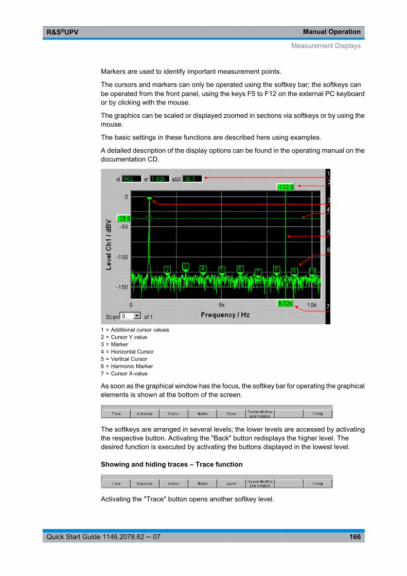
Manual OperationR&S®UPV
166Quick Start Guide 1146.2078.62 ─ 07
Markers are used to identify important measurement points.
The cursors and markers can only be operated using the softkey bar; the softkeys canbe operated from the front panel, using the keys F5 to F12 on the external PC keyboardor by clicking with the mouse.
The graphics can be scaled or displayed zoomed in sections via softkeys or by using themouse.
The basic settings in these functions are described here using examples.
A detailed description of the display options can be found in the operating manual on thedocumentation CD.
1 = Additional cursor values2 = Cursor Y value3 = Marker4 = Horizontal Cursor5 = Vertical Cursor6 = Harmonic Marker7 = Cursor X-value
As soon as the graphical window has the focus, the softkey bar for operating the graphicalelements is shown at the bottom of the screen.
The softkeys are arranged in several levels; the lower levels are accessed by activatingthe respective button. Activating the "Back" button redisplays the higher level. Thedesired function is executed by activating the buttons displayed in the lowest level.
Showing and hiding traces – Trace function
Activating the "Trace" button opens another softkey level.
Measurement Displays
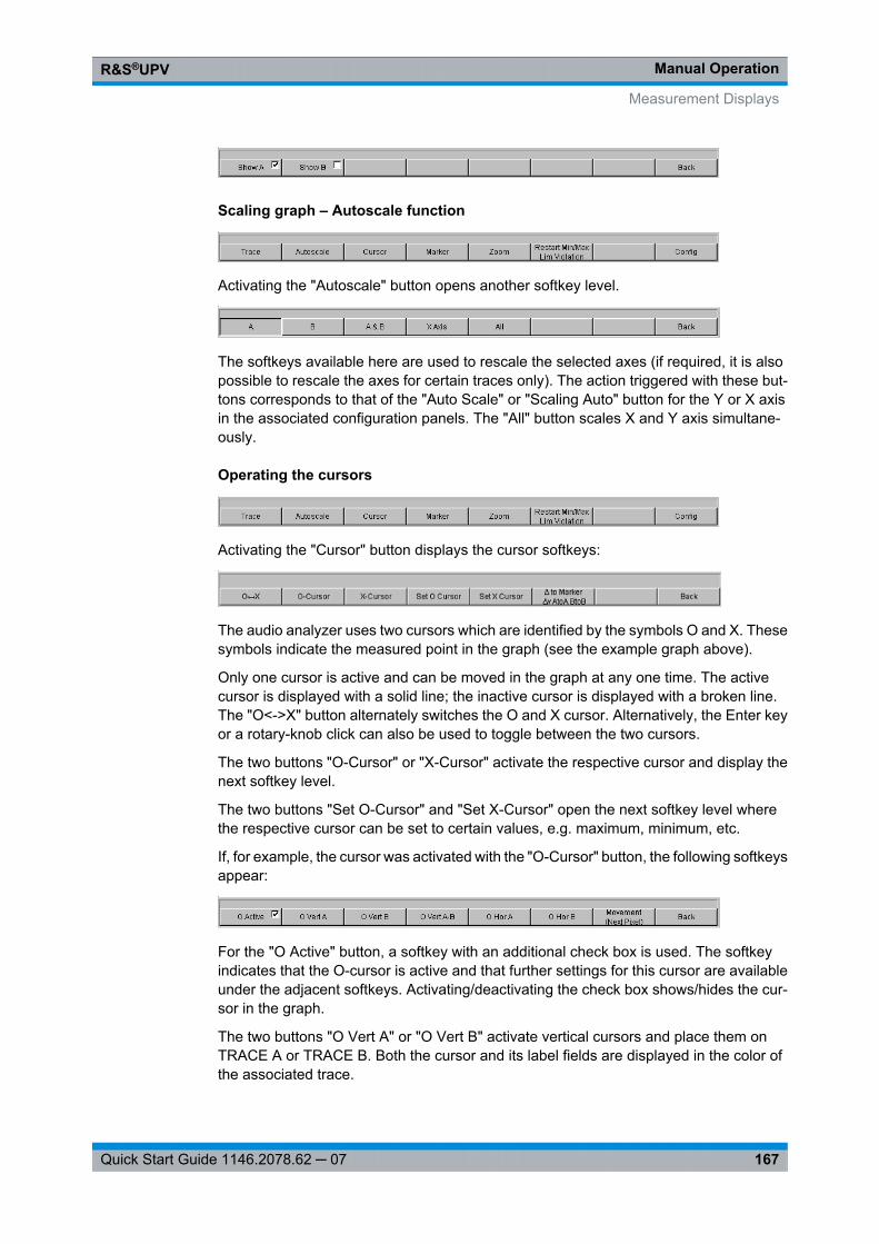
Manual OperationR&S®UPV
167Quick Start Guide 1146.2078.62 ─ 07
Scaling graph – Autoscale function
Activating the "Autoscale" button opens another softkey level.
The softkeys available here are used to rescale the selected axes (if required, it is alsopossible to rescale the axes for certain traces only). The action triggered with these but-tons corresponds to that of the "Auto Scale" or "Scaling Auto" button for the Y or X axisin the associated configuration panels. The "All" button scales X and Y axis simultane-ously.
Operating the cursors
Activating the "Cursor" button displays the cursor softkeys:
The audio analyzer uses two cursors which are identified by the symbols O and X. Thesesymbols indicate the measured point in the graph (see the example graph above).
Only one cursor is active and can be moved in the graph at any one time. The activecursor is displayed with a solid line; the inactive cursor is displayed with a broken line.The "O<->X" button alternately switches the O and X cursor. Alternatively, the Enter keyor a rotary-knob click can also be used to toggle between the two cursors.
The two buttons "O-Cursor" or "X-Cursor" activate the respective cursor and display thenext softkey level.
The two buttons "Set O-Cursor" and "Set X-Cursor" open the next softkey level wherethe respective cursor can be set to certain values, e.g. maximum, minimum, etc.
If, for example, the cursor was activated with the "O-Cursor" button, the following softkeysappear:
For the "O Active" button, a softkey with an additional check box is used. The softkeyindicates that the O-cursor is active and that further settings for this cursor are availableunder the adjacent softkeys. Activating/deactivating the check box shows/hides the cur-sor in the graph.
The two buttons "O Vert A" or "O Vert B" activate vertical cursors and place them onTRACE A or TRACE B. Both the cursor and its label fields are displayed in the color ofthe associated trace.
Measurement Displays
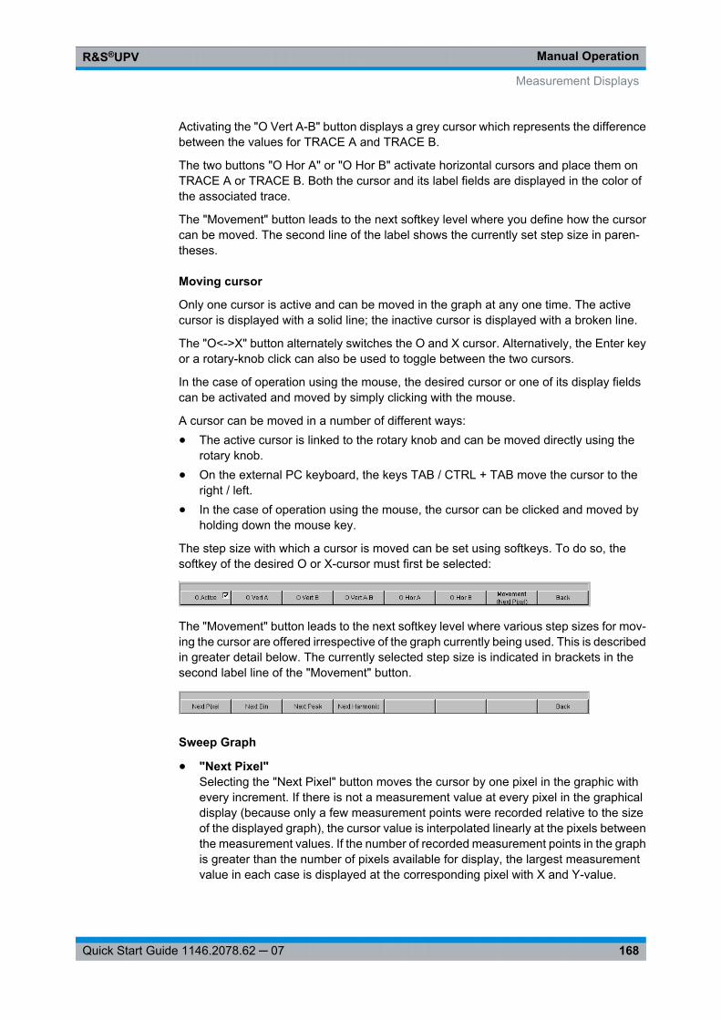
Manual OperationR&S®UPV
168Quick Start Guide 1146.2078.62 ─ 07
Activating the "O Vert A-B" button displays a grey cursor which represents the differencebetween the values for TRACE A and TRACE B.
The two buttons "O Hor A" or "O Hor B" activate horizontal cursors and place them onTRACE A or TRACE B. Both the cursor and its label fields are displayed in the color ofthe associated trace.
The "Movement" button leads to the next softkey level where you define how the cursorcan be moved. The second line of the label shows the currently set step size in paren-theses.
Moving cursor
Only one cursor is active and can be moved in the graph at any one time. The activecursor is displayed with a solid line; the inactive cursor is displayed with a broken line.
The "O<->X" button alternately switches the O and X cursor. Alternatively, the Enter keyor a rotary-knob click can also be used to toggle between the two cursors.
In the case of operation using the mouse, the desired cursor or one of its display fieldscan be activated and moved by simply clicking with the mouse.
A cursor can be moved in a number of different ways:● The active cursor is linked to the rotary knob and can be moved directly using the
rotary knob.● On the external PC keyboard, the keys TAB / CTRL + TAB move the cursor to the
right / left.● In the case of operation using the mouse, the cursor can be clicked and moved by
holding down the mouse key.
The step size with which a cursor is moved can be set using softkeys. To do so, thesoftkey of the desired O or X-cursor must first be selected:
The "Movement" button leads to the next softkey level where various step sizes for mov-ing the cursor are offered irrespective of the graph currently being used. This is describedin greater detail below. The currently selected step size is indicated in brackets in thesecond label line of the "Movement" button.
Sweep Graph
● "Next Pixel"Selecting the "Next Pixel" button moves the cursor by one pixel in the graphic withevery increment. If there is not a measurement value at every pixel in the graphicaldisplay (because only a few measurement points were recorded relative to the sizeof the displayed graph), the cursor value is interpolated linearly at the pixels betweenthe measurement values. If the number of recorded measurement points in the graphis greater than the number of pixels available for display, the largest measurementvalue in each case is displayed at the corresponding pixel with X and Y-value.
Measurement Displays

Manual OperationR&S®UPV
169Quick Start Guide 1146.2078.62 ─ 07
● "Next Step"Selecting the "Next Step" button moves the cursor to the next measured value withevery increment. The cursor is therefore moved in smaller or larger steps dependingon the number of measurement points. If the graph is displayed relatively small orthe number of recorded measurement values displayed is greater than the numberof pixels available in the graphical field, the cursor sometimes does not appear tomove (it remains on the same pixel). However, the associated display fields alwaysshow the currently selected measurement point with X and Y-value.
● "Next Peak"Selecting the "Next Peak" button moves the cursor to the next measured peak withevery increment.
FFT Graph
● "Next Pixel"Selecting the "Next Pixel" button moves the cursor by one pixel in the graphic withevery increment.With FFT analyses, the number of recorded measurement points (bins) is usuallymuch greater than the number of pixels available for display in the graph; the cursorthen indicates the bin with the largest measurement value at the pixel in question anddisplays this bin with its X and Y-values.
● "Next Bin"Selecting the "Next Bin" button moves the cursor to the next measured bin with everyincrement.Since with FFT analyses the number of recorded measurement points (bins) is usu-ally much greater than the number of pixels available for display, the cursor some-times does not appear to move (it remains on the same pixel). However, the associ-ated display fields always show the currently selected measurement point with X andY-value.
● "Next Peak"Selecting the "Next Peak" button moves the cursor to the next measured peak withevery increment.
● "Next Harmonic"Selecting the "Next Harmonic" button moves the cursor to the next marked harmonicwith every increment.This button is also available if the harmonic marker is not active (see the next section,Operating the markers). In this case, the button activates the harmonic marker.
Waveform
● "Next Pixel"Selecting the "Next Pixel" button moves the cursor by one pixel in the graphic withevery increment.If there is not a measurement value at every pixel in the graphical display (becauseonly a few measurement points were recorded relative to the size of the displayedgraph), the cursor value is interpolated linearly at the pixels between the measure-ment values.If the number of recorded measurement points in the graph is greater than the numberof pixels available for display, the largest measurement value in each case is dis-played at the corresponding pixel with X and Y-value.
Measurement Displays
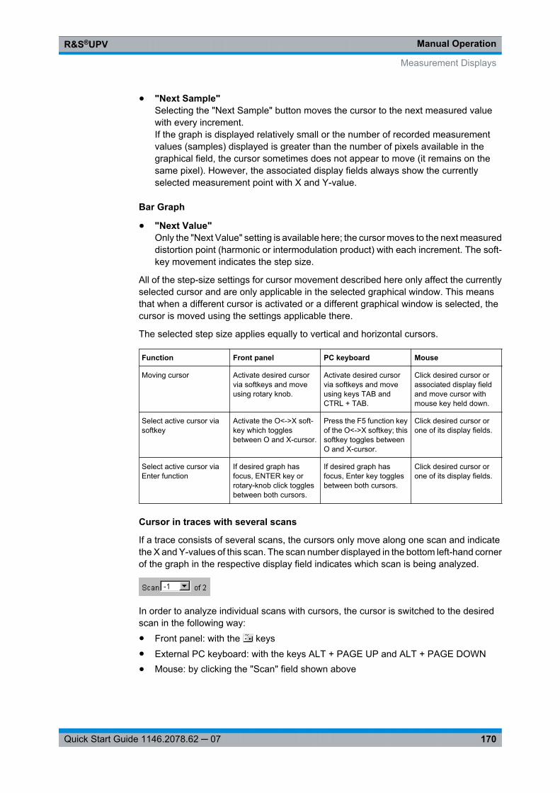
Manual OperationR&S®UPV
170Quick Start Guide 1146.2078.62 ─ 07
● "Next Sample"Selecting the "Next Sample" button moves the cursor to the next measured valuewith every increment.If the graph is displayed relatively small or the number of recorded measurementvalues (samples) displayed is greater than the number of pixels available in thegraphical field, the cursor sometimes does not appear to move (it remains on thesame pixel). However, the associated display fields always show the currentlyselected measurement point with X and Y-value.
Bar Graph
● "Next Value"Only the "Next Value" setting is available here; the cursor moves to the next measureddistortion point (harmonic or intermodulation product) with each increment. The soft-key movement indicates the step size.
All of the step-size settings for cursor movement described here only affect the currentlyselected cursor and are only applicable in the selected graphical window. This meansthat when a different cursor is activated or a different graphical window is selected, thecursor is moved using the settings applicable there.
The selected step size applies equally to vertical and horizontal cursors.
Function Front panel PC keyboard Mouse
Moving cursor Activate desired cursorvia softkeys and moveusing rotary knob.
Activate desired cursorvia softkeys and moveusing keys TAB andCTRL + TAB.
Click desired cursor orassociated display fieldand move cursor withmouse key held down.
Select active cursor viasoftkey
Activate the O<->X soft-key which togglesbetween O and X-cursor.
Press the F5 function keyof the O<->X softkey; thissoftkey toggles betweenO and X-cursor.
Click desired cursor orone of its display fields.
Select active cursor viaEnter function
If desired graph hasfocus, ENTER key orrotary-knob click togglesbetween both cursors.
If desired graph hasfocus, Enter key togglesbetween both cursors.
Click desired cursor orone of its display fields.
Cursor in traces with several scans
If a trace consists of several scans, the cursors only move along one scan and indicatethe X and Y-values of this scan. The scan number displayed in the bottom left-hand cornerof the graph in the respective display field indicates which scan is being analyzed.
In order to analyze individual scans with cursors, the cursor is switched to the desiredscan in the following way:● Front panel: with the keys● External PC keyboard: with the keys ALT + PAGE UP and ALT + PAGE DOWN● Mouse: by clicking the "Scan" field shown above
Measurement Displays
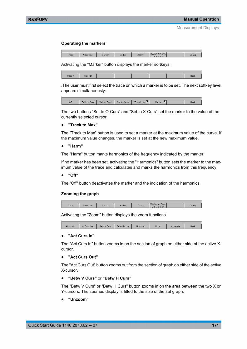
Manual OperationR&S®UPV
171Quick Start Guide 1146.2078.62 ─ 07
Operating the markers
Activating the "Marker" button displays the marker softkeys:
.The user must first select the trace on which a marker is to be set. The next softkey levelappears simultaneously:
The two buttons "Set to O-Curs" and "Set to X-Curs" set the marker to the value of thecurrently selected cursor.
● "Track to Max"
The "Track to Max" button is used to set a marker at the maximum value of the curve. Ifthe maximum value changes, the marker is set at the new maximum value.
● "Harm"
The "Harm" button marks harmonics of the frequency indicated by the marker.
If no marker has been set, activating the "Harmonics" button sets the marker to the max-imum value of the trace and calculates and marks the harmonics from this frequency.
● "Off"
The "Off" button deactivates the marker and the indication of the harmonics.
Zooming the graph
Activating the "Zoom" button displays the zoom functions.
● "Act Curs In"
The "Act Curs In" button zooms in on the section of graph on either side of the active X-cursor.
● "Act Curs Out"
The "Act Curs Out" button zooms out from the section of graph on either side of the activeX-cursor.
● "Betw V Curs" or "Betw H Curs"
The "Betw V Curs" or "Betw H Curs" button zooms in on the area between the two X orY-cursors. The zoomed display is fitted to the size of the set graph.
● "Unzoom"
Measurement Displays
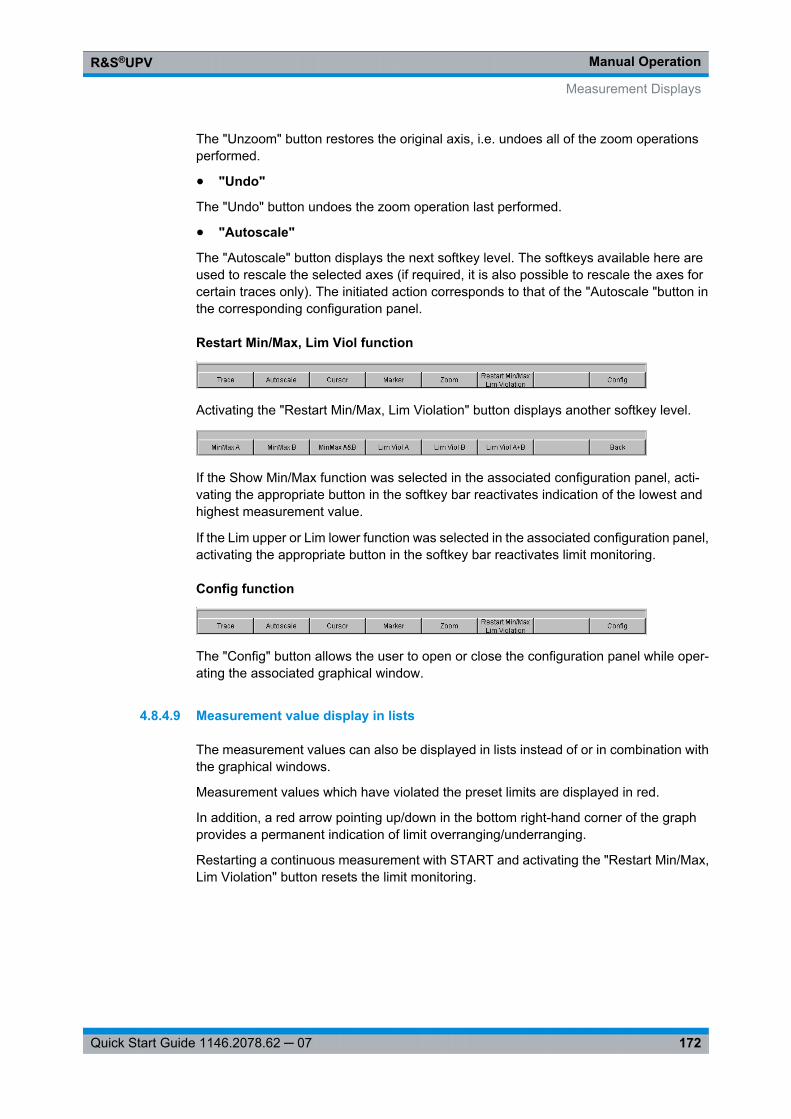
Manual OperationR&S®UPV
172Quick Start Guide 1146.2078.62 ─ 07
The "Unzoom" button restores the original axis, i.e. undoes all of the zoom operationsperformed.
● "Undo"
The "Undo" button undoes the zoom operation last performed.
● "Autoscale"
The "Autoscale" button displays the next softkey level. The softkeys available here areused to rescale the selected axes (if required, it is also possible to rescale the axes forcertain traces only). The initiated action corresponds to that of the "Autoscale "button inthe corresponding configuration panel.
Restart Min/Max, Lim Viol function
Activating the "Restart Min/Max, Lim Violation" button displays another softkey level.
If the Show Min/Max function was selected in the associated configuration panel, acti-vating the appropriate button in the softkey bar reactivates indication of the lowest andhighest measurement value.
If the Lim upper or Lim lower function was selected in the associated configuration panel,activating the appropriate button in the softkey bar reactivates limit monitoring.
Config function
The "Config" button allows the user to open or close the configuration panel while oper-ating the associated graphical window.
4.8.4.9 Measurement value display in lists
The measurement values can also be displayed in lists instead of or in combination withthe graphical windows.
Measurement values which have violated the preset limits are displayed in red.
In addition, a red arrow pointing up/down in the bottom right-hand corner of the graphprovides a permanent indication of limit overranging/underranging.
Restarting a continuous measurement with START and activating the "Restart Min/Max,Lim Violation" button resets the limit monitoring.
Measurement Displays
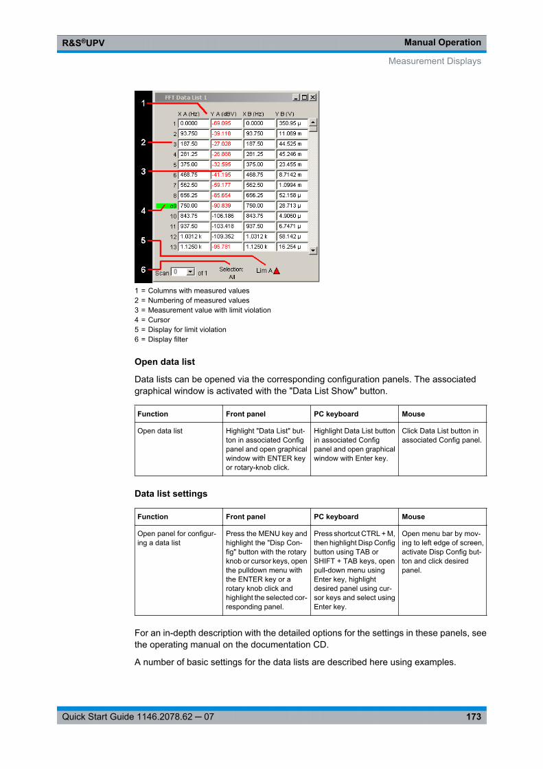
Manual OperationR&S®UPV
173Quick Start Guide 1146.2078.62 ─ 07
1 = Columns with measured values2 = Numbering of measured values3 = Measurement value with limit violation4 = Cursor5 = Display for limit violation6 = Display filter
Open data list
Data lists can be opened via the corresponding configuration panels. The associatedgraphical window is activated with the "Data List Show" button.
Function Front panel PC keyboard Mouse
Open data list Highlight "Data List" but-ton in associated Configpanel and open graphicalwindow with ENTER keyor rotary-knob click.
Highlight Data List buttonin associated Configpanel and open graphicalwindow with Enter key.
Click Data List button inassociated Config panel.
Data list settings
Function Front panel PC keyboard Mouse
Open panel for configur-ing a data list
Press the MENU key andhighlight the "Disp Con-fig" button with the rotaryknob or cursor keys, openthe pulldown menu withthe ENTER key or arotary knob click andhighlight the selected cor-responding panel.
Press shortcut CTRL + M,then highlight Disp Configbutton using TAB orSHIFT + TAB keys, openpull-down menu usingEnter key, highlightdesired panel using cur-sor keys and select usingEnter key.
Open menu bar by mov-ing to left edge of screen,activate Disp Config but-ton and click desiredpanel.
For an in-depth description with the detailed options for the settings in these panels, seethe operating manual on the documentation CD.
A number of basic settings for the data lists are described here using examples.
Measurement Displays
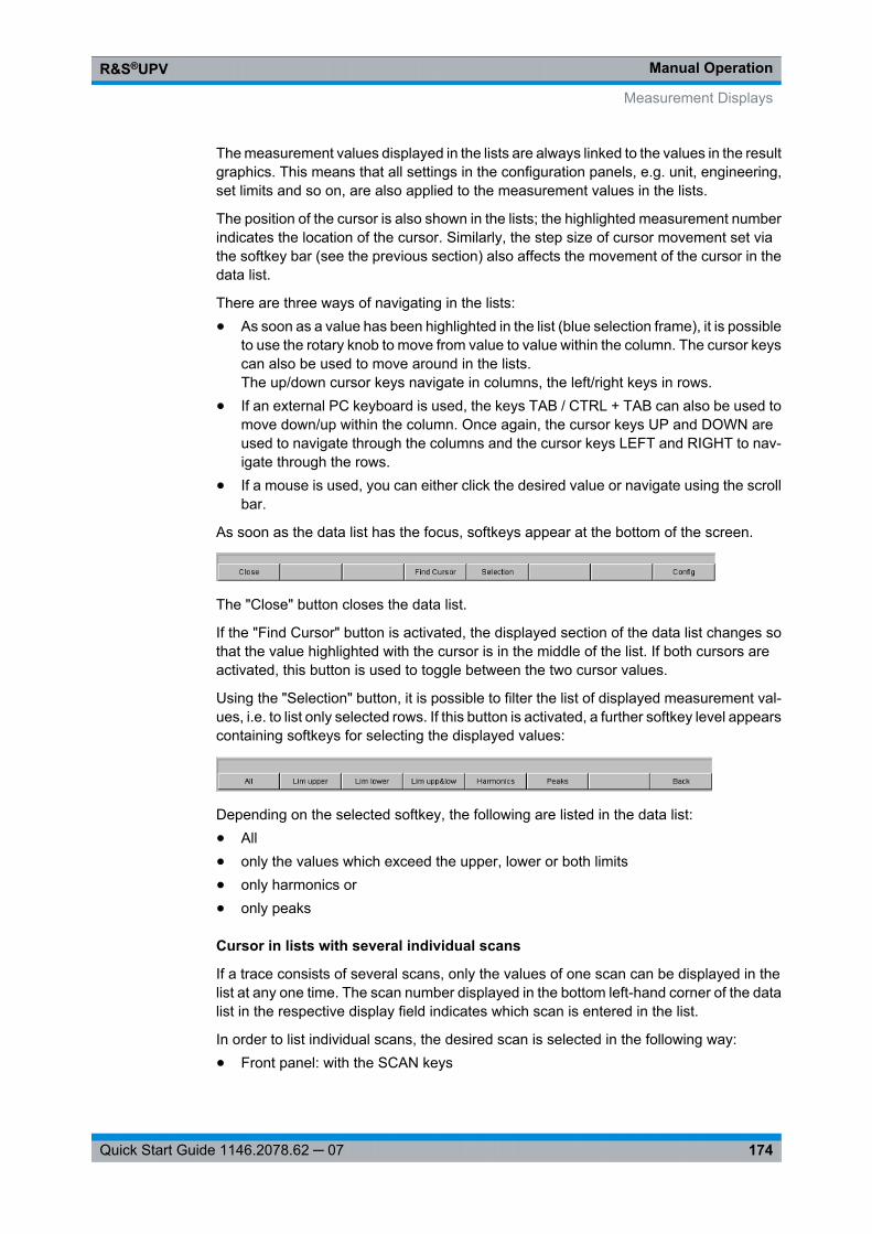
Manual OperationR&S®UPV
174Quick Start Guide 1146.2078.62 ─ 07
The measurement values displayed in the lists are always linked to the values in the resultgraphics. This means that all settings in the configuration panels, e.g. unit, engineering,set limits and so on, are also applied to the measurement values in the lists.
The position of the cursor is also shown in the lists; the highlighted measurement numberindicates the location of the cursor. Similarly, the step size of cursor movement set viathe softkey bar (see the previous section) also affects the movement of the cursor in thedata list.
There are three ways of navigating in the lists:● As soon as a value has been highlighted in the list (blue selection frame), it is possible
to use the rotary knob to move from value to value within the column. The cursor keyscan also be used to move around in the lists.The up/down cursor keys navigate in columns, the left/right keys in rows.
● If an external PC keyboard is used, the keys TAB / CTRL + TAB can also be used tomove down/up within the column. Once again, the cursor keys UP and DOWN areused to navigate through the columns and the cursor keys LEFT and RIGHT to nav-igate through the rows.
● If a mouse is used, you can either click the desired value or navigate using the scrollbar.
As soon as the data list has the focus, softkeys appear at the bottom of the screen.
The "Close" button closes the data list.
If the "Find Cursor" button is activated, the displayed section of the data list changes sothat the value highlighted with the cursor is in the middle of the list. If both cursors areactivated, this button is used to toggle between the two cursor values.
Using the "Selection" button, it is possible to filter the list of displayed measurement val-ues, i.e. to list only selected rows. If this button is activated, a further softkey level appearscontaining softkeys for selecting the displayed values:
Depending on the selected softkey, the following are listed in the data list:● All● only the values which exceed the upper, lower or both limits● only harmonics or● only peaks
Cursor in lists with several individual scans
If a trace consists of several scans, only the values of one scan can be displayed in thelist at any one time. The scan number displayed in the bottom left-hand corner of the datalist in the respective display field indicates which scan is entered in the list.
In order to list individual scans, the desired scan is selected in the following way:● Front panel: with the SCAN keys
Measurement Displays
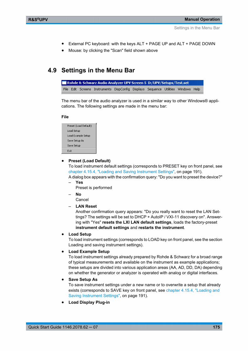
Manual OperationR&S®UPV
175Quick Start Guide 1146.2078.62 ─ 07
● External PC keyboard: with the keys ALT + PAGE UP and ALT + PAGE DOWN● Mouse: by clicking the "Scan" field shown above
4.9 Settings in the Menu Bar
The menu bar of the audio analyzer is used in a similar way to other Windows® appli-cations. The following settings are made in the menu bar:
File
● Preset (Load Default)To load instrument default settings (corresponds to PRESET key on front panel, seechapter 4.15.4, "Loading and Saving Instrument Settings", on page 191).A dialog box appears with the confirmation query: "Do you want to preset the device?"– Yes
Preset is performed– No
Cancel– LAN Reset
Another confirmation query appears: "Do you really want to reset the LAN Set-tings? The settings will be set to DHCP + AutoIP / VXI-11 discovery on". Answer-ing with "Yes" resets the LXI LAN default settings, loads the factory-presetinstrument default settings and restarts the instrument.
● Load SetupTo load instrument settings (corresponds to LOAD key on front panel, see the sectionLoading and saving instrument settings).
● Load Example SetupTo load instrument settings already prepared by Rohde & Schwarz for a broad rangeof typical measurements and available on the instrument as example applications;these setups are divided into various application areas (AA, AD, DD, DA) dependingon whether the generator or analyzer is operated with analog or digital interfaces.
● Save Setup AsTo save instrument settings under a new name or to overwrite a setup that alreadyexists (corresponds to SAVE key on front panel, see chapter 4.15.4, "Loading andSaving Instrument Settings", on page 191).
● Load Display Plug-in
Settings in the Menu Bar
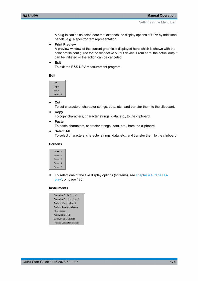
Manual OperationR&S®UPV
176Quick Start Guide 1146.2078.62 ─ 07
A plug-in can be selected here that expands the display options of UPV by additionalpanels, e.g. a spectrogram representation.
● Print PreviewA preview window of the current graphic is displayed here which is shown with thecolor profile configured for the respective output device. From here, the actual outputcan be initiated or the action can be canceled.
● ExitTo exit the R&S UPV measurement program.
Edit
● CutTo cut characters, character strings, data, etc., and transfer them to the clipboard.
● CopyTo copy characters, character strings, data, etc., to the clipboard.
● PasteTo paste characters, character strings, data, etc., from the clipboard.
● Select AllTo select characters, character strings, data, etc., and transfer them to the clipboard.
Screens
● To select one of the five display options (screens), see chapter 4.4, "The Dis-play", on page 120.
Instruments
Settings in the Menu Bar
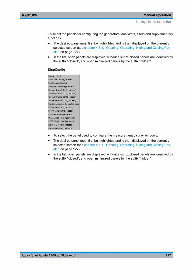
Manual OperationR&S®UPV
177Quick Start Guide 1146.2078.62 ─ 07
To select the panels for configuring the generators, analyzers, filters and supplementaryfunctions.● The desired panel must first be highlighted and is then displayed on the currently
selected screen (see chapter 4.5.1, "Opening, Operating, Hiding and Closing Pan-els", on page 127)
● In the list, open panels are displayed without a suffix, closed panels are identified bythe suffix "closed", and open minimized panels by the suffix "hidden".
DispConfig
● To select the panel used to configure the measurement display windows.● The desired panel must first be highlighted and is then displayed on the currently
selected screen (see chapter 4.5.1, "Opening, Operating, Hiding and Closing Pan-els", on page 127)
● In the list, open panels are displayed without a suffix, closed panels are identified bythe suffix "closed", and open minimized panels by the suffix "hidden".
Settings in the Menu Bar
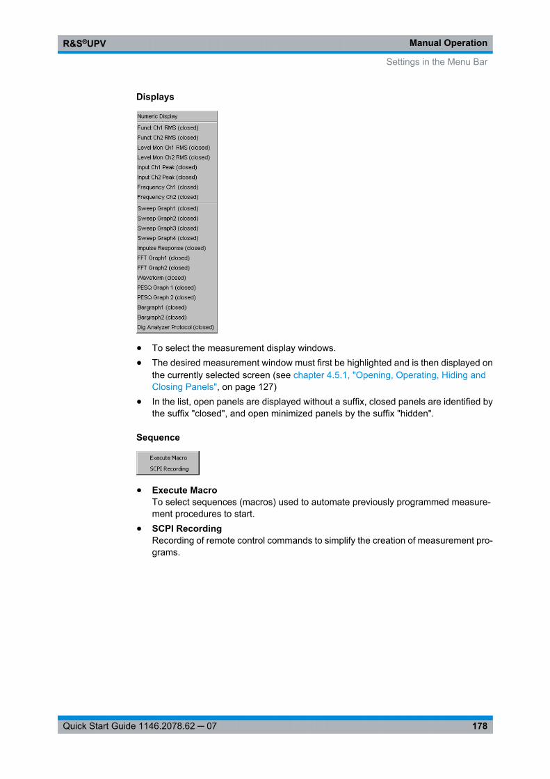
Manual OperationR&S®UPV
178Quick Start Guide 1146.2078.62 ─ 07
Displays
● To select the measurement display windows.● The desired measurement window must first be highlighted and is then displayed on
the currently selected screen (see chapter 4.5.1, "Opening, Operating, Hiding andClosing Panels", on page 127)
● In the list, open panels are displayed without a suffix, closed panels are identified bythe suffix "closed", and open minimized panels by the suffix "hidden".
Sequence
● Execute MacroTo select sequences (macros) used to automate previously programmed measure-ment procedures to start.
● SCPI RecordingRecording of remote control commands to simplify the creation of measurement pro-grams.
Settings in the Menu Bar
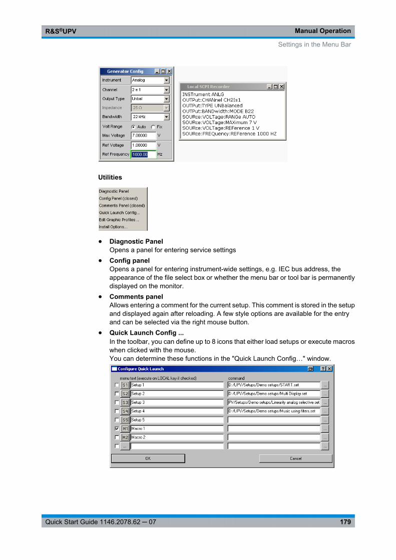
Manual OperationR&S®UPV
179Quick Start Guide 1146.2078.62 ─ 07
Utilities
● Diagnostic PanelOpens a panel for entering service settings
● Config panelOpens a panel for entering instrument-wide settings, e.g. IEC bus address, theappearance of the file select box or whether the menu bar or tool bar is permanentlydisplayed on the monitor.
● Comments panelAllows entering a comment for the current setup. This comment is stored in the setupand displayed again after reloading. A few style options are available for the entryand can be selected via the right mouse button.
● Quick Launch Config ...In the toolbar, you can define up to 8 icons that either load setups or execute macroswhen clicked with the mouse.You can determine these functions in the "Quick Launch Config…" window.
Settings in the Menu Bar
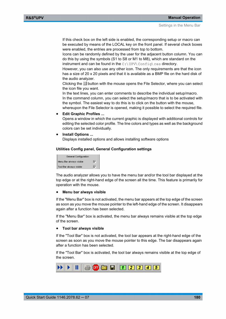
Manual OperationR&S®UPV
180Quick Start Guide 1146.2078.62 ─ 07
If this check box on the left side is enabled, the corresponding setup or macro canbe executed by means of the LOCAL key on the front panel. If several check boxeswere enabled, the entries are processed from top to bottom.Icons can be randomly defined by the user for the adjacent button column. You cando this by using the symbols (S1 to S8 or M1 to M8), which are standard on theinstrument and can be found in the C:\UPV\Config\res directory.However, you can also use any other icon. The only requirements are that the iconhas a size of 20 x 20 pixels and that it is available as a BMP file on the hard disk ofthe audio analyzer.Clicking the button with the mouse opens the File Selector, where you can selectthe icon file you want.In the text lines, you can enter comments to describe the individual setup/macro.In the command column, you can select the setup/macro that is to be activated withthe symbol. The easiest way to do this is to click on the button with the mouse,whereupon the File Selector is opened, making it possible to select the required file.
● Edit Graphic Profiles ...Opens a window in which the current graphic is displayed with additional controls forediting the selected color profile. The line colors and types as well as the backgroundcolors can be set individually.
● Install Options ...Displays installed options and allows installing software options
Utilities Config panel, General Configuration settings
The audio analyzer allows you to have the menu bar and/or the tool bar displayed at thetop edge or at the right-hand edge of the screen all the time. This feature is primarily foroperation with the mouse.
● Menu bar always visible
If the "Menu Bar" box is not activated, the menu bar appears at the top edge of the screenas soon as you move the mouse pointer to the left-hand edge of the screen. It disappearsagain after a function has been selected.
If the "Menu Bar" box is activated, the menu bar always remains visible at the top edgeof the screen.
● Tool bar always visible
If the "Tool Bar" box is not activated, the tool bar appears at the right-hand edge of thescreen as soon as you move the mouse pointer to this edge. The bar disappears againafter a function has been selected.
If the "Tool Bar" box is activated, the tool bar always remains visible at the top edge ofthe screen.
Settings in the Menu Bar
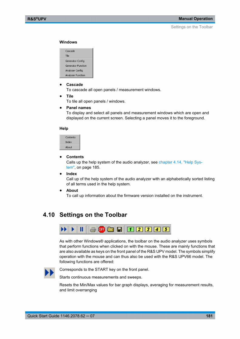
Manual OperationR&S®UPV
181Quick Start Guide 1146.2078.62 ─ 07
Windows
● CascadeTo cascade all open panels / measurement windows.
● TileTo tile all open panels / windows.
● Panel namesTo display and select all panels and measurement windows which are open anddisplayed on the current screen. Selecting a panel moves it to the foreground.
Help
● ContentsCalls up the help system of the audio analyzer, see chapter 4.14, "Help Sys-tem", on page 185.
● IndexCall up of the help system of the audio analyzer with an alphabetically sorted listingof all terms used in the help system.
● AboutTo call up information about the firmware version installed on the instrument.
4.10 Settings on the Toolbar
As with other Windows® applications, the toolbar on the audio analyzer uses symbolsthat perform functions when clicked on with the mouse. These are mainly functions thatare also available as keys on the front panel of the R&S UPV model. The symbols simplifyoperation with the mouse and can thus also be used with the R&S UPV66 model. Thefollowing functions are offered:
Corresponds to the START key on the front panel.
Starts continuous measurements and sweeps.
Resets the Min/Max values for bar graph displays, averaging for measurement results,and limit overranging
Settings on the Toolbar
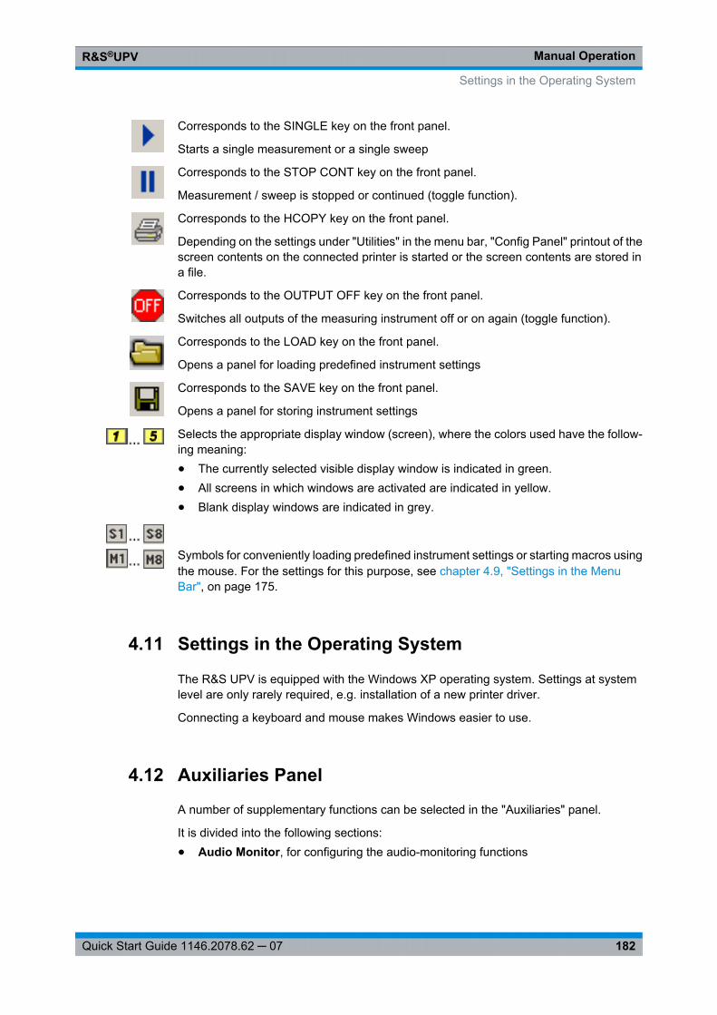
Manual OperationR&S®UPV
182Quick Start Guide 1146.2078.62 ─ 07
Corresponds to the SINGLE key on the front panel.
Starts a single measurement or a single sweep
Corresponds to the STOP CONT key on the front panel.
Measurement / sweep is stopped or continued (toggle function).
Corresponds to the HCOPY key on the front panel.
Depending on the settings under "Utilities" in the menu bar, "Config Panel" printout of thescreen contents on the connected printer is started or the screen contents are stored ina file.
Corresponds to the OUTPUT OFF key on the front panel.
Switches all outputs of the measuring instrument off or on again (toggle function).
Corresponds to the LOAD key on the front panel.
Opens a panel for loading predefined instrument settings
Corresponds to the SAVE key on the front panel.
Opens a panel for storing instrument settings
Selects the appropriate display window (screen), where the colors used have the follow-ing meaning:● The currently selected visible display window is indicated in green.● All screens in which windows are activated are indicated in yellow.● Blank display windows are indicated in grey.
Symbols for conveniently loading predefined instrument settings or starting macros usingthe mouse. For the settings for this purpose, see chapter 4.9, "Settings in the MenuBar", on page 175.
4.11 Settings in the Operating System
The R&S UPV is equipped with the Windows XP operating system. Settings at systemlevel are only rarely required, e.g. installation of a new printer driver.
Connecting a keyboard and mouse makes Windows easier to use.
4.12 Auxiliaries Panel
A number of supplementary functions can be selected in the "Auxiliaries" panel.
It is divided into the following sections:● Audio Monitor, for configuring the audio-monitoring functions
Settings in the Operating System
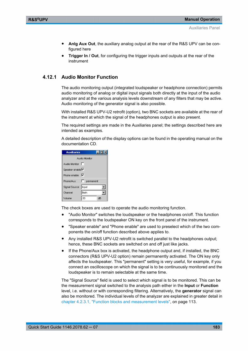
Manual OperationR&S®UPV
183Quick Start Guide 1146.2078.62 ─ 07
● Anlg Aux Out, the auxiliary analog output at the rear of the R&S UPV can be con-figured here
● Trigger In / Out, for configuring the trigger inputs and outputs at the rear of theinstrument
4.12.1 Audio Monitor Function
The audio monitoring output (integrated loudspeaker or headphone connection) permitsaudio monitoring of analog or digital input signals both directly at the input of the audioanalyzer and at the various analysis levels downstream of any filters that may be active.Audio monitoring of the generator signal is also possible.
With installed R&S UPV-U2 retrofit (option), two BNC sockets are available at the rear ofthe instrument at which the signal of the headphones output is also present.
The required settings are made in the Auxiliaries panel; the settings described here areintended as examples.
A detailed description of the display options can be found in the operating manual on thedocumentation CD.
The check boxes are used to operate the audio monitoring function.● "Audio Monitor" switches the loudspeaker or the headphones on/off. This function
corresponds to the loudspeaker ON key on the front panel of the instrument.● "Speaker enable" and "Phone enable" are used to preselect which of the two com-
ponents the on/off function described above applies to.● Any installed R&S UPV-U2 retrofit is switched parallel to the headphones output;
hence, these BNC sockets are switched on and off just like jacks.● If the Phone/Aux box is activated, the headphone output and, if installed, the BNC
connectors (R&S UPV-U2 option) remain permanently activated. The ON key onlyaffects the loudspeaker. This "permanent" setting is very useful, for example, if youconnect an oscilloscope on which the signal is to be continuously monitored and theloudspeaker is to remain selectable at the same time.
The "Signal Source" field is used to select which signal is to be monitored. This can bethe measurement signal switched to the analysis path either in the Input or Functionlevel, i.e. without or with corresponding filtering. Alternatively, the generator signal canalso be monitored. The individual levels of the analyzer are explained in greater detail inchapter 4.2.3.1, "Function blocks and measurement levels", on page 113.
Auxiliaries Panel
Manual OperationR&S®UPV
184Quick Start Guide 1146.2078.62 ─ 07
In the "Channel" field, you select whether the signal of an individual channel (mono) orthe stereo signal is applied to the audio monitoring output. If "Both" is set, both channelsare separately available at the two headphone outputs; the loudspeaker outputs the sig-nal from both channels. The same applies with installed R&SUPV-U2 retrofit for the twoBNC sockets that are present.
In the "Volume" field, the playback volume of the loudspeaker or connected headphonesis set by entering or changing the numeric value in the range from 0 dB to -120 dB.
Alternatively, the loudspeaker key at the front of the instrument can be used. A windowwith a symbolized volume control opens which can be operated directly with the rotaryknob, the cursor keys or the mouse. The ENTER function or pressing the volume keyagain confirms the setting and closes the window.
Possible hearing damage from high sound pressureThe output voltage of the built-in headphones amplifier is influenced by the incomingsignal, by instrument settings such as the selected measurement range and test function,and by the set volume.If the volume is set to maximum, the headphones amplifier may generate high outputvoltages with an RMS value of up to 8 V.Depending on the headphones' sensitivity, this may produce very high sound pressurelevels that may cause hearing damage.To monitor varying input signals, therefore, it is advisable to reduce the volume and takeoff the headphones until the signal has settled.
4.12.2 Auxiliary analog output
An auxiliary analog output, ANLG AUX OUT, for the following special applications is pro-vided at the rear:
● Output of a DC signal, e.g. for supplying power to hearing aids● Auxiliary output for the analog generator signal via an integrated amplifier for the
direct activation of small loudspeakers● Output for single-channel audio monitoring
For details, see the operating manual on the documentation CD.
4.12.3 Trigger Input, Trigger Output
A trigger input and trigger output for the following applications are provided at the rear:● Input for triggering measurements● Output for a measurement-event-dependent signal that can be used to trigger exter-
nal instruments / circuits● Alternatively, clock signals can also be output at the TRIGOUT socket
Auxiliaries Panel
Manual OperationR&S®UPV
185Quick Start Guide 1146.2078.62 ─ 07
4.13 Rapid Deactivation of Outputs
The OUTPUT OFF key can be used in the event of faults to deactivate the outputs of thegenerator. This means:● The levels of all digital outputs are set to 0 V.● The levels of all analog outputs are set to 0 V, whereby the outputs remain terminated
(i.e., the impedance is retained).
The deactivated lines can only be reactivated by pressing the OUTPUT OFF key again.
Specialty Anlg Aux Output:
If DC is selected as signal source in the "Anlg Aux Out" line in the Auxiliaries panel, theDC voltage indicated in the line below will be retained even if you press the OUTPUTOFF key.
This ensures the supply voltage or the operation point is retained when a device undertest (DUT) is connected.
The status of the key is indicated by an LED. Illumination of the LED means OUTPUTOFF.
In case of an overload of the analyzer inputs (input voltage at 300 Ω or 600 Ω greaterthan 25 V), the generator output is automatically switched off and the OUTPUT-OFF LEDlights up as if the OUTPUT-OFF key has been pressed to protect the analyzer input. Afterthe analyzer inputs have been overloaded in this way, measurements can be resumedprovided that the overvoltage has been rectified or the input impedance has beenswitched to 200 kΩ.
4.14 Help System
The R&S UPV has a context-sensitive help system. The help system provides a helppage for every parameter and can be called up at any time while the instrument is beingoperated. The help system has a navigation bar, i.e. starting from the context-sensitivepage it is possible to move to other help pages using the contents list, the index, scrollarrows and page-internal links.
Rapid Deactivation of Outputs
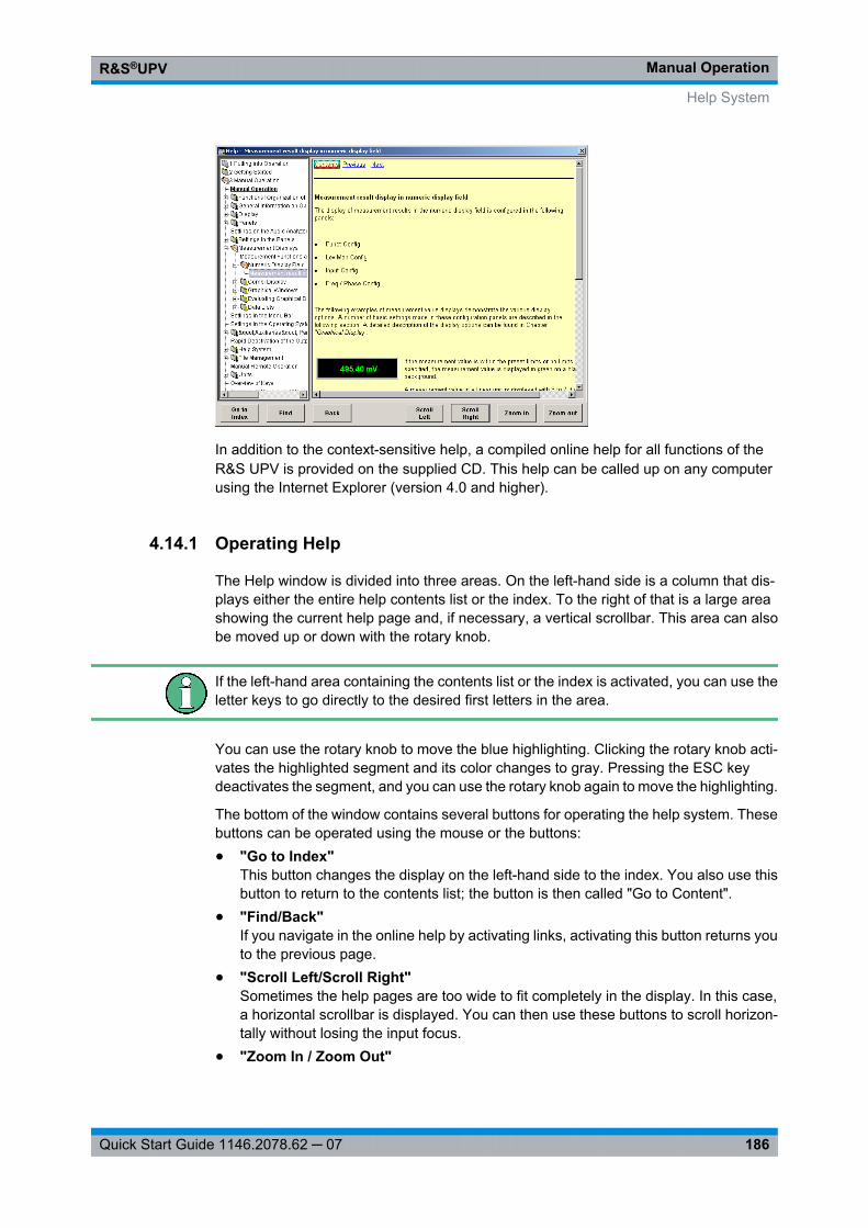
Manual OperationR&S®UPV
186Quick Start Guide 1146.2078.62 ─ 07
In addition to the context-sensitive help, a compiled online help for all functions of theR&S UPV is provided on the supplied CD. This help can be called up on any computerusing the Internet Explorer (version 4.0 and higher).
4.14.1 Operating Help
The Help window is divided into three areas. On the left-hand side is a column that dis-plays either the entire help contents list or the index. To the right of that is a large areashowing the current help page and, if necessary, a vertical scrollbar. This area can alsobe moved up or down with the rotary knob.
If the left-hand area containing the contents list or the index is activated, you can use theletter keys to go directly to the desired first letters in the area.
You can use the rotary knob to move the blue highlighting. Clicking the rotary knob acti-vates the highlighted segment and its color changes to gray. Pressing the ESC keydeactivates the segment, and you can use the rotary knob again to move the highlighting.
The bottom of the window contains several buttons for operating the help system. Thesebuttons can be operated using the mouse or the buttons:● "Go to Index"
This button changes the display on the left-hand side to the index. You also use thisbutton to return to the contents list; the button is then called "Go to Content".
● "Find/Back"If you navigate in the online help by activating links, activating this button returns youto the previous page.
● "Scroll Left/Scroll Right"Sometimes the help pages are too wide to fit completely in the display. In this case,a horizontal scrollbar is displayed. You can then use these buttons to scroll horizon-tally without losing the input focus.
● "Zoom In / Zoom Out"
Help System
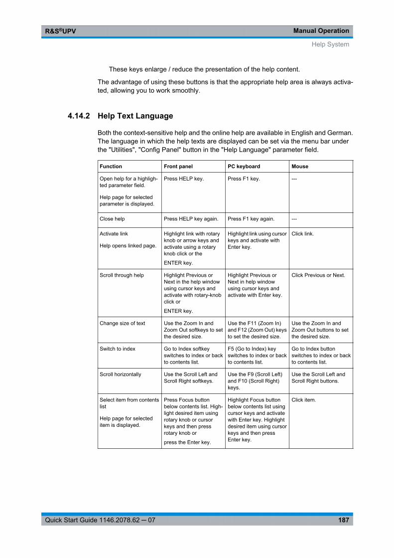
Manual OperationR&S®UPV
187Quick Start Guide 1146.2078.62 ─ 07
These keys enlarge / reduce the presentation of the help content.
The advantage of using these buttons is that the appropriate help area is always activa-ted, allowing you to work smoothly.
4.14.2 Help Text Language
Both the context-sensitive help and the online help are available in English and German.The language in which the help texts are displayed can be set via the menu bar underthe "Utilities", "Config Panel" button in the "Help Language" parameter field.
Function Front panel PC keyboard Mouse
Open help for a highligh-ted parameter field.
Help page for selectedparameter is displayed.
Press HELP key. Press F1 key. ---
Close help Press HELP key again. Press F1 key again. ---
Activate link
Help opens linked page.
Highlight link with rotaryknob or arrow keys andactivate using a rotaryknob click or the
ENTER key.
Highlight link using cursorkeys and activate withEnter key.
Click link.
Scroll through help Highlight Previous orNext in the help windowusing cursor keys andactivate with rotary-knobclick or
ENTER key.
Highlight Previous orNext in help windowusing cursor keys andactivate with Enter key.
Click Previous or Next.
Change size of text Use the Zoom In andZoom Out softkeys to setthe desired size.
Use the F11 (Zoom In)and F12 (Zoom Out) keysto set the desired size.
Use the Zoom In andZoom Out buttons to setthe desired size.
Switch to index Go to Index softkeyswitches to index or backto contents list.
F5 (Go to Index) keyswitches to index or backto contents list.
Go to Index buttonswitches to index or backto contents list.
Scroll horizontally Use the Scroll Left andScroll Right softkeys.
Use the F9 (Scroll Left)and F10 (Scroll Right)keys.
Use the Scroll Left andScroll Right buttons.
Select item from contentslist
Help page for selecteditem is displayed.
Press Focus buttonbelow contents list. High-light desired item usingrotary knob or cursorkeys and then pressrotary knob or
press the Enter key.
Highlight Focus buttonbelow contents list usingcursor keys and activatewith Enter key. Highlightdesired item using cursorkeys and then pressEnter key.
Click item.
Help System
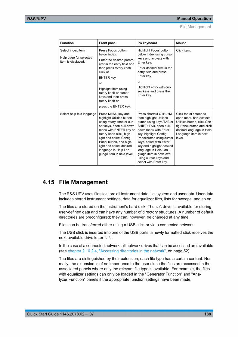
Manual OperationR&S®UPV
188Quick Start Guide 1146.2078.62 ─ 07
Function Front panel PC keyboard Mouse
Select index item
Help page for selecteditem is displayed.
Press Focus buttonbelow index.
Enter the desired param-eter in the entry field andthen press rotary knobclick or
ENTER key
or
Highlight item usingrotary knob or cursorkeys and then pressrotary knob or
press the ENTER key.
Highlight Focus buttonbelow index using cursorkeys and activate withEnter key.
Enter desired item in theentry field and pressEnter key
or
Highlight entry with cur-sor keys and press theEnter key.
Click item.
Select help text language Press MENU key andhighlight Utilities buttonusing rotary knob or cur-sor keys, open pull-downmenu with ENTER key orrotary-knob click, high-light and select ConfigPanel button, and high-light and select desiredlanguage in Help Lan-guage item in next level.
Press shortcut CTRL+M,then highlight Utilitiesbutton using keys TAB orSHIFT+TAB, open pull-down menu with Enterkey, highlight ConfigPanel button using cursorkeys, select with Enterkey and highlight desiredlanguage in Help Lan-guage item in next levelusing cursor keys andselect with Enter key.
Click top of screen toopen menu bar, activateUtilities button, click Con-fig Panel button and clickdesired language in HelpLanguage item in nextlevel.
4.15 File Management
The R&S UPV uses files to store all instrument data, i.e. system and user data. User dataincludes stored instrument settings, data for equalizer files, lists for sweeps, and so on.
The files are stored on the instrument's hard disk. The D:\drive is available for storinguser-defined data and can have any number of directory structures. A number of defaultdirectories are preconfigured; they can, however, be changed at any time.
Files can be transferred either using a USB stick or via a connected network.
The USB stick is inserted into one of the USB ports; a newly formatted stick receives thenext available drive letter E:\.
In the case of a connected network, all network drives that can be accessed are available(see chapter 2.10.2.4, "Accessing directories in the network", on page 52).
The files are distinguished by their extension; each file type has a certain content. Nor-mally, the extension is of no importance to the user since the files are accessed in theassociated panels where only the relevant file type is available. For example, the fileswith equalizer settings can only be loaded in the "Generator Function" and "Ana-lyzer Function" panels if the appropriate function settings have been made.
File Management
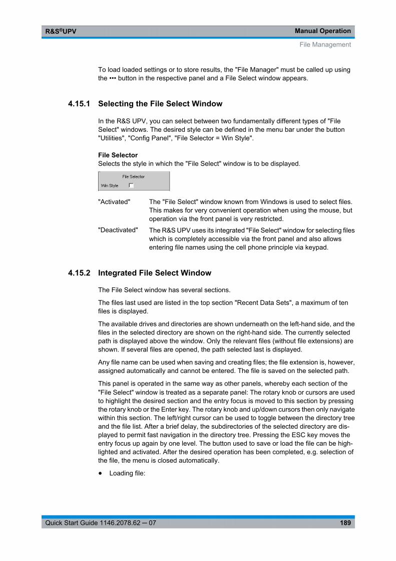
Manual OperationR&S®UPV
189Quick Start Guide 1146.2078.62 ─ 07
To load loaded settings or to store results, the "File Manager" must be called up usingthe ••• button in the respective panel and a File Select window appears.
4.15.1 Selecting the File Select Window
In the R&S UPV, you can select between two fundamentally different types of "FileSelect" windows. The desired style can be defined in the menu bar under the button"Utilities", "Config Panel", "File Selector = Win Style".
File SelectorSelects the style in which the "File Select" window is to be displayed.
"Activated" The "File Select" window known from Windows is used to select files.This makes for very convenient operation when using the mouse, butoperation via the front panel is very restricted.
"Deactivated" The R&S UPV uses its integrated "File Select" window for selecting fileswhich is completely accessible via the front panel and also allowsentering file names using the cell phone principle via keypad.
4.15.2 Integrated File Select Window
The File Select window has several sections.
The files last used are listed in the top section "Recent Data Sets", a maximum of tenfiles is displayed.
The available drives and directories are shown underneath on the left-hand side, and thefiles in the selected directory are shown on the right-hand side. The currently selectedpath is displayed above the window. Only the relevant files (without file extensions) areshown. If several files are opened, the path selected last is displayed.
Any file name can be used when saving and creating files; the file extension is, however,assigned automatically and cannot be entered. The file is saved on the selected path.
This panel is operated in the same way as other panels, whereby each section of the"File Select" window is treated as a separate panel: The rotary knob or cursors are usedto highlight the desired section and the entry focus is moved to this section by pressingthe rotary knob or the Enter key. The rotary knob and up/down cursors then only navigatewithin this section. The left/right cursor can be used to toggle between the directory treeand the file list. After a brief delay, the subdirectories of the selected directory are dis-played to permit fast navigation in the directory tree. Pressing the ESC key moves theentry focus up again by one level. The button used to save or load the file can be high-lighted and activated. After the desired operation has been completed, e.g. selection ofthe file, the menu is closed automatically.
● Loading file:
File Management
Manual OperationR&S®UPV
190Quick Start Guide 1146.2078.62 ─ 07
Highlight the file and load by pressing the rotary knob or activating the Select button/softkey.
● Saving file:Enter the file name in the "File Name:" field. Highlight the directory in which the fileis to be saved and then activate the "Save" button/softkey.
● Creating file:Enter the file name in the "File Name:" field. Highlight the directory in which the fileis to be saved and then activate the "Create" button/softkey. The created file is empty;it has to be filled with the desired values using the associated editor.
4.15.3 File Manager
The File Manager is used to perform general file management tasks, such as copying,moving, renaming and deleting files and creating new directories. This also allows savingexternally created files in the R&S UPV by copying them to the internal hard disk from aUSB stick, a CD or a network.
The "File Manager" can be called up in all panels in which files can be loaded. It is calledup using the "File Manager…" button in the "File Select" window.
Additionally, it is also possible to call up the File Manager via the menu bar.
The file types to be displayed can be selected in the "File Type" section at the top of theFile Manager. All files ("All Files (*:*)") or specific file types (e.g. "Waveforms (*.wav)")can be selected. A list of file types is given in the panel at the end of this section.
The available drives and directories are shown underneath on the left-hand side, and thefiles in the selected directory are shown on the right-hand side. The currently selectedpath is displayed above the window. If several files are opened, the path selected last isdisplayed. Unlike the "File Select" window, displays the complete file name including theextension.
The buttons/softkeys trigger the assigned action, e.g. copying, moving or deleting thehighlighted file. In addition, it is possible to create a new directory in the level below thehighlighted directory.
This panel is operated in the same way as other panels, whereby each section of the"File Select" window is treated as a separate panel: The rotary knob or cursors are usedto highlight the desired section and the entry focus is moved to this section by pressingthe rotary knob or the Enter key. The rotary knob and up/down cursors then only navigatewithin this section. The left/right cursor can be used to toggle between the directory treeand the file list. After a brief delay, the subdirectories of the selected directory are dis-played to permit fast navigation in the directory tree. Pressing the ESC key moves theentry focus up again by one level. The buttons/softkeys can be selected and activated.
● Moving file:Highlight the file and then activate the "Cut" button/softkey. Highlight the directory towhich the file is to be moved and then activate the Paste button/softkey. If a file withthe same name already exists in the target directory, a confirmation query appearswhich the user must acknowledge before the file is overwritten.
● Copying file:
File Management
Manual OperationR&S®UPV
191Quick Start Guide 1146.2078.62 ─ 07
Highlight the file and then activate the "Copy" button/softkey. Highlight the directoryto which the file is to be copied and then activate the Paste button/softkey. If a filewith the same name already exists in the target directory, a confirmation queryappears which the user must acknowledge before the file is overwritten.
● Renaming file:Highlight the file and then activate the "Rename" button/softkey. A window opens inwhich the new file name can be entered. Enter the name and press the Enter key. Ifa file with the same name already exists, a confirmation query appears which theuser must acknowledge before the file is overwritten.
● Deleting file:Highlight the file and then activate the "Delete" button/softkey. A confirmation querythen appears which the user must acknowledge before the file is deleted.
● Creating a new directory:Highlight the drive or directory level under which the new directory is to be created,and then activate the "Create New Directory" button/softkey. A window opens inwhich the new directory name can be entered. Enter the name and press the Enterkey.
4.15.4 Loading and Saving Instrument Settings
With the menu bar and the button "File", "Load Setup", "Load Example Setup", "SaveSetup as", "Save Setup" or "Load Display Plug-in", the "File Select" window is called up.
Instrument settings can also be loaded/saved directly using the LOAD / SAVE keys onthe front of the instrument. Pressing these keys opens the "File Select" window.
Every R&S UPV audio analyzer has a range of instrument settings which have beenprepared by Rohde & Schwarz for a broad selection of typical measurements and whichare available on the instrument as sample setups. These setups are divided into differentapplication areas (AA, AD, DD, DA), depending on whether generator or analyzer isoperated with analog or digital interfaces, and are selected via the menu bar, "File" and"Load Example Setup".
This allows users to make settings for their own specific measurement tasks very simplyby modifying these example setups.
All of these sample settings are located in the directory D:\UPV\Setup Examples.
Every R&S UPV also features the factory-based default instrument setting. These canbe called up directly using the File button on the menu bar or by pressing the PRESETkey on the front of the instrument.
File Management
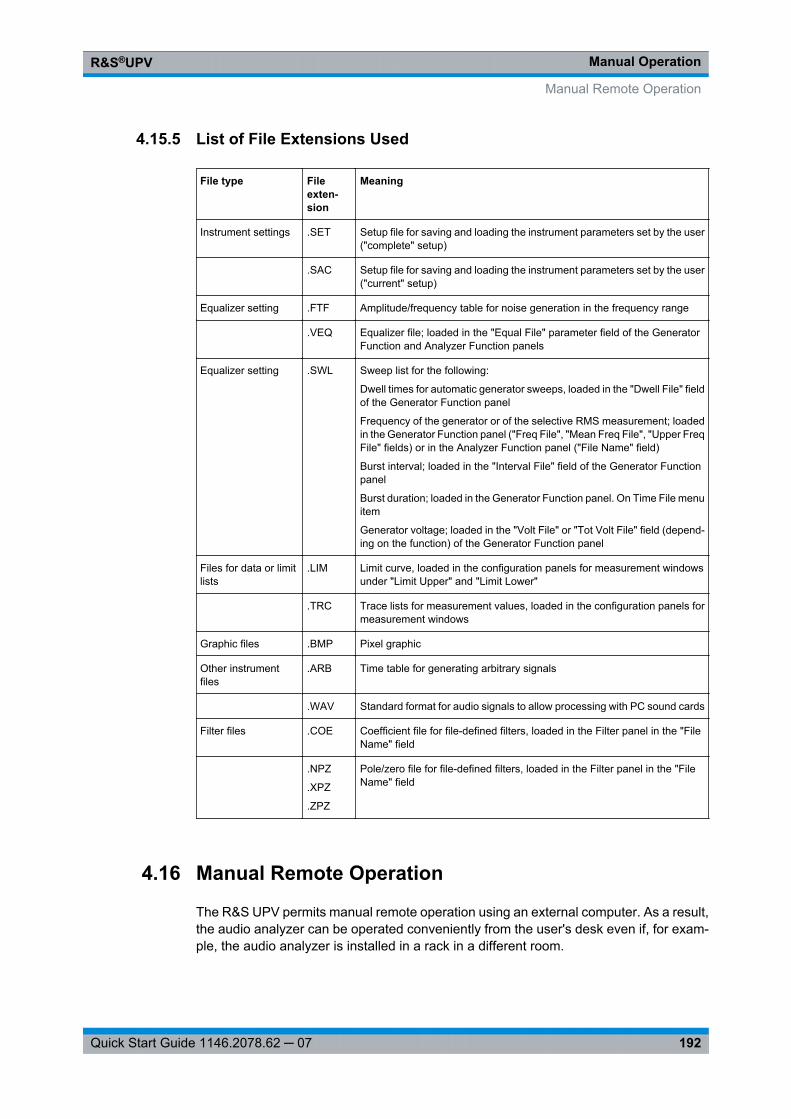
Manual OperationR&S®UPV
192Quick Start Guide 1146.2078.62 ─ 07
4.15.5 List of File Extensions Used
File type Fileexten-sion
Meaning
Instrument settings .SET Setup file for saving and loading the instrument parameters set by the user("complete" setup)
.SAC Setup file for saving and loading the instrument parameters set by the user("current" setup)
Equalizer setting .FTF Amplitude/frequency table for noise generation in the frequency range
.VEQ Equalizer file; loaded in the "Equal File" parameter field of the GeneratorFunction and Analyzer Function panels
Equalizer setting .SWL Sweep list for the following:
Dwell times for automatic generator sweeps, loaded in the "Dwell File" fieldof the Generator Function panel
Frequency of the generator or of the selective RMS measurement; loadedin the Generator Function panel ("Freq File", "Mean Freq File", "Upper FreqFile" fields) or in the Analyzer Function panel ("File Name" field)
Burst interval; loaded in the "Interval File" field of the Generator Functionpanel
Burst duration; loaded in the Generator Function panel. On Time File menuitem
Generator voltage; loaded in the "Volt File" or "Tot Volt File" field (depend-ing on the function) of the Generator Function panel
Files for data or limitlists
.LIM Limit curve, loaded in the configuration panels for measurement windowsunder "Limit Upper" and "Limit Lower"
.TRC Trace lists for measurement values, loaded in the configuration panels formeasurement windows
Graphic files .BMP Pixel graphic
Other instrumentfiles
.ARB Time table for generating arbitrary signals
.WAV Standard format for audio signals to allow processing with PC sound cards
Filter files .COE Coefficient file for file-defined filters, loaded in the Filter panel in the "FileName" field
.NPZ
.XPZ
.ZPZ
Pole/zero file for file-defined filters, loaded in the Filter panel in the "FileName" field
4.16 Manual Remote Operation
The R&S UPV permits manual remote operation using an external computer. As a result,the audio analyzer can be operated conveniently from the user's desk even if, for exam-ple, the audio analyzer is installed in a rack in a different room.
Manual Remote Operation

Manual OperationR&S®UPV
193Quick Start Guide 1146.2078.62 ─ 07
Unlike remote operation where remote-control commands are used, the manualremote operation requires separate Windows software which is installed on the externalcomputer. When launched, the Windows software Remote Desktop Connection simu-lates the user interface of the R&S UPV. This allows the instrument to be manually oper-ated at the external computer in the same way as at the instrument itself.
Manual remote operation is only possible if the audio analyzer and computer are con-nected via LAN and the Windows software is installed on the computer.
Establishing the connection and installation of the remote-control software on the externalPC is described in chapter 2.10.4, "Configuration for manual remote opera-tion", on page 60.
Manual remote operation is started on the external computer by calling up the RemoteDesktop Connection program and clicking on the Connect button. The R&S UPV mustbe selected as the remote operation device, i.e. its computer name must be displayed inthe Computer: If the computer has been configured for remote operation of more thanone instrument, the desired instrument can be selected from the list which is displayedby clicking the button. The user ID and password (instrument in both cases) can bestored when the software is first installed. The entry is possible in the expanded"Options>>" menu.
After logon, the instrument firmware of R&S UPV boots on the external computer. Afterthe completion of the boot process, the screen of the audio analyzer appears and theR&S UPV can be manually remote-controlled from the external computer. The startingconfiguration is that which was active before the connection was set up. The individualfunctions are operated using the mouse and panel. Front panel keys which are not directlyavailable on the panel may be replaced by shortcuts (see chapter 4.18, "Overview ofKeys", on page 200).
When establishing the connection, the instrument firmware at the R&S UPV is exited.During the manual remote control, it is not possible to perform any operations at theR&S UPV itself. Access by an external computer and the identity of the remote user isindicated on the login display of Windows.
To return to direct operation at the R&S UPV, it is necessary to log off the external userand log on the local user.
The external user can be logged off at the external computer in the "Start" menu of theR&S UPV window by clicking on "Disconnect" in the bottom right menu area.
Manual Remote Operation
Manual OperationR&S®UPV
194Quick Start Guide 1146.2078.62 ─ 07
Logging off is also possible directly at the R&S UPV in the remote control window.
The local user can be logged on at the R&S UPV in the remote control screen only afterpressing the shortcut Ctrl + Alt + Del. By default, the R&S UPV uses instrument for thisuser name, and the password is also instrument.
After login, the instrument software starts with the settings used for manual remote oper-ation.
4.17 Units
The R&S UPV features two types of units:● Units for measurement result display:
In the configuration panels for the measurement displays, a display unit must beselected for each measurement function. This unit is then used for the measurementresult displayed in the measurement display windows. The unit is selected in the Unitfields of the respective panel.
● Units for value entries (e.g. reference values, frequencies, levels, etc.):When data is entered, the available units are displayed on the softkeys. This allowsvalue entries to be adopted by selecting the unit without a further entry window havingto be opened.
4.17.1 Units in Measurement Result Displays
To simplify matters: In the following conversion formulas, the entry values are designatedby the unit only. Example: "dBu" means: value in "dBu".
4.17.1.1 Units for analog level measurement results
Basic unit: V
Units
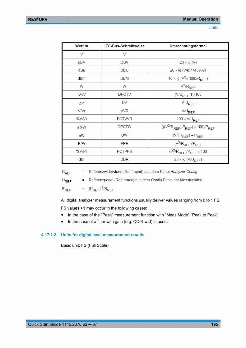
Manual OperationR&S®UPV
195Quick Start Guide 1146.2078.62 ─ 07
All digital analyzer measurement functions usually deliver values ranging from 0 to 1 FS.
FS values >1 may occur in the following cases:● In the case of the "Peak" measurement function with "Meas Mode" "Peak to Peak"● In the case of a filter with gain (e.g. CCIR wtd) is used.
4.17.1.2 Units for digital level measurement results
Basic unit: FS (Full Scale)
Units
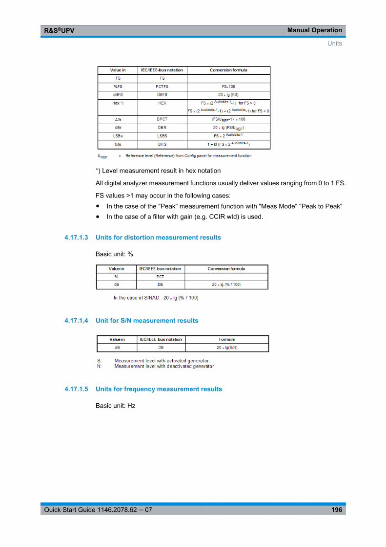
Manual OperationR&S®UPV
196Quick Start Guide 1146.2078.62 ─ 07
*) Level measurement result in hex notation
All digital analyzer measurement functions usually deliver values ranging from 0 to 1 FS.
FS values >1 may occur in the following cases:● In the case of the "Peak" measurement function with "Meas Mode" "Peak to Peak"● In the case of a filter with gain (e.g. CCIR wtd) is used.
4.17.1.3 Units for distortion measurement results
Basic unit: %
4.17.1.4 Unit for S/N measurement results
4.17.1.5 Units for frequency measurement results
Basic unit: Hz
Units
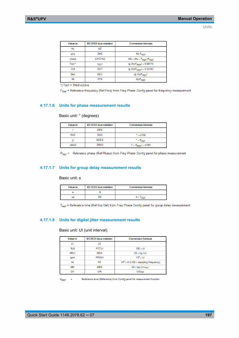
Manual OperationR&S®UPV
197Quick Start Guide 1146.2078.62 ─ 07
4.17.1.6 Units for phase measurement results
Basic unit: ° (degrees)
4.17.1.7 Units for group delay measurement results
Basic unit: s
4.17.1.8 Units for digital jitter measurement results
Basic unit: UI (unit interval)
Units
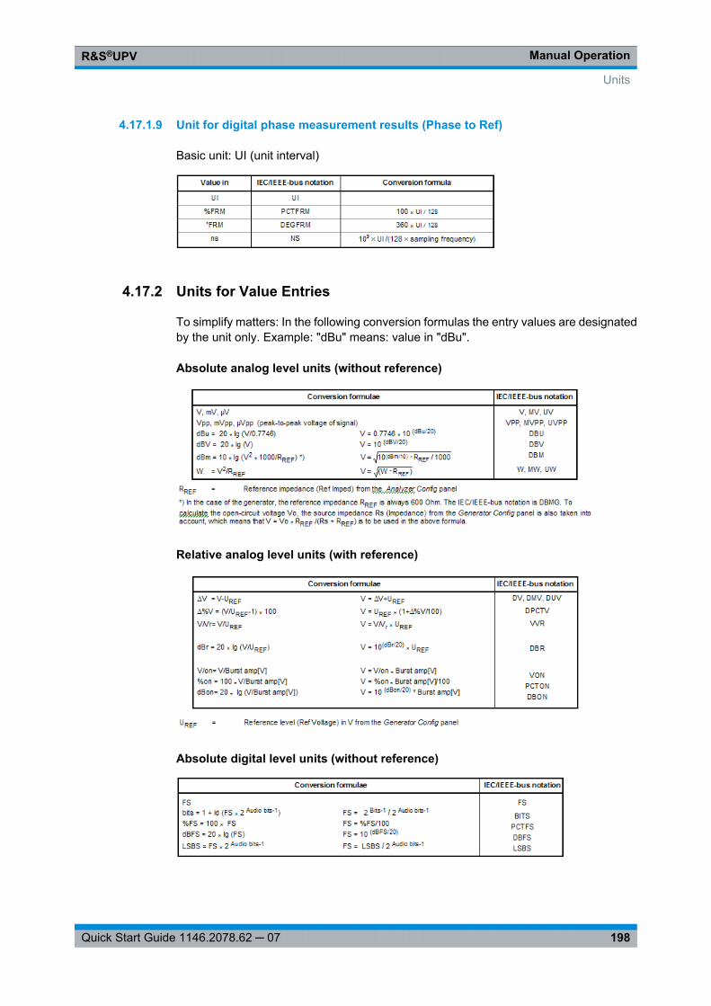
Manual OperationR&S®UPV
198Quick Start Guide 1146.2078.62 ─ 07
4.17.1.9 Unit for digital phase measurement results (Phase to Ref)
Basic unit: UI (unit interval)
4.17.2 Units for Value Entries
To simplify matters: In the following conversion formulas the entry values are designatedby the unit only. Example: "dBu" means: value in "dBu".
Absolute analog level units (without reference)
Relative analog level units (with reference)
Absolute digital level units (without reference)
Units
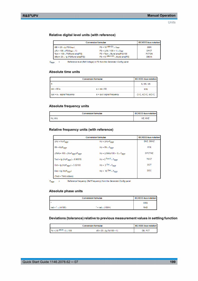
Manual OperationR&S®UPV
199Quick Start Guide 1146.2078.62 ─ 07
Relative digital level units (with reference)
Absolute time units
Absolute frequency units
Relative frequency units (with reference)
Absolute phase units
Deviations (tolerance) relative to previous measurement values in settling function
Units
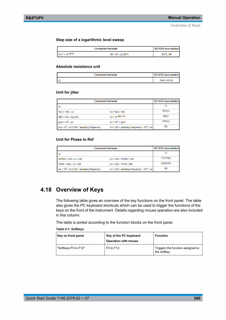
Manual OperationR&S®UPV
200Quick Start Guide 1146.2078.62 ─ 07
Step size of a logarithmic level sweep
Absolute resistance unit
Unit for jitter
Unit for Phase to Ref
4.18 Overview of Keys
The following table gives an overview of the key functions on the front panel. The tablealso gives the PC keyboard shortcuts which can be used to trigger the functions of thekeys on the front of the instrument. Details regarding mouse operation are also includedin this column.
The table is sorted according to the function blocks on the front panel.
Table 4-1: Softkeys
Key on front panel Key of the PC keyboard
Operation with mouse
Function
"Softkeys F5 to F12" F5 to F12 Triggers the function assigned tothe softkey.
Overview of Keys
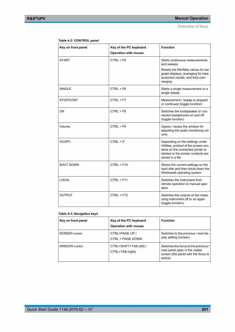
Manual OperationR&S®UPV
201Quick Start Guide 1146.2078.62 ─ 07
Table 4-2: CONTROL panel
Key on front panel Key of the PC keyboard
Operation with mouse
Function
START CTRL + F5 Starts continuous measurementsand sweeps
Resets the Min/Max values for bargraph displays, averaging for mea-surement results, and limit over-ranging
SINGLE CTRL + F6 Starts a single measurement or asingle sweep
STOP/CONT CTRL + F7 Measurement / sweep is stoppedor continued (toggle function)
ON CTRL + F8 Switches the loudspeaker or con-nected headphones on and off(toggle function)
Volume CTRL + F9 Opens / closes the window foradjusting the audio monitoring vol-ume
HCOPY CTRL + P Depending on the settings underUtilities, printout of the screen con-tents on the connected printer isstarted or the screen contents arestored in a file
SHUT DOWN CTRL + F10 Stores the current settings on thehard disk and then shuts down theWindows® operating system
LOCAL CTRL + F11 Switches the instrument fromremote operation to manual oper-ation
OUTPUT CTRL + F12 Switches the outputs of the meas-uring instrument off or on again(toggle function)
Table 4-3: Navigation keys
Key on front panel Key of the PC keyboard
Operation with mouse
Function
SCREEN cursor CTRL+PAGE UP /
CTRL + PAGE DOWN
Switches to the previous / next dis-play setting (screen)
WINDOW cursor CTRL+SHIFT+TAB (left) /
CTRL+TAB (right)
Switches the focus to the previous /next panel open in the visiblescreen (the panel with the focus isactive)
Overview of Keys
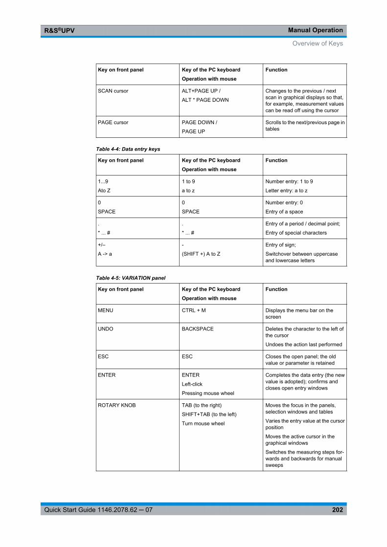
Manual OperationR&S®UPV
202Quick Start Guide 1146.2078.62 ─ 07
Key on front panel Key of the PC keyboard
Operation with mouse
Function
SCAN cursor ALT+PAGE UP /
ALT * PAGE DOWN
Changes to the previous / nextscan in graphical displays so that,for example, measurement valuescan be read off using the cursor
PAGE cursor PAGE DOWN /
PAGE UP
Scrolls to the next/previous page intables
Table 4-4: Data entry keys
Key on front panel Key of the PC keyboard
Operation with mouse
Function
1...9
Ato Z
1 to 9
a to z
Number entry: 1 to 9
Letter entry: a to z
0
SPACE
0
SPACE
Number entry: 0
Entry of a space
.
* ... #
.
* ... #
Entry of a period / decimal point;
Entry of special characters
+/–
A -> a
-
(SHIFT +) A to Z
Entry of sign;
Switchover between uppercaseand lowercase letters
Table 4-5: VARIATION panel
Key on front panel Key of the PC keyboard
Operation with mouse
Function
MENU CTRL + M Displays the menu bar on thescreen
UNDO BACKSPACE Deletes the character to the left ofthe cursor
Undoes the action last performed
ESC ESC Closes the open panel; the oldvalue or parameter is retained
ENTER ENTER
Left-click
Pressing mouse wheel
Completes the data entry (the newvalue is adopted); confirms andcloses open entry windows
ROTARY KNOB TAB (to the right)
SHIFT+TAB (to the left)
Turn mouse wheel
Moves the focus in the panels,selection windows and tables
Varies the entry value at the cursorposition
Moves the active cursor in thegraphical windows
Switches the measuring steps for-wards and backwards for manualsweeps
Overview of Keys
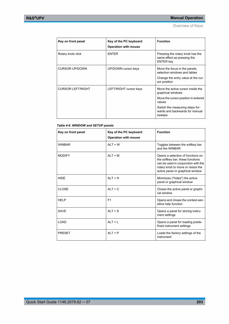
Manual OperationR&S®UPV
203Quick Start Guide 1146.2078.62 ─ 07
Key on front panel Key of the PC keyboard
Operation with mouse
Function
Rotary knob click ENTER Pressing the rotary knob has thesame effect as pressing theENTER key
CURSOR UP/DOWN UP/DOWN cursor keys Move the focus in the panels,selection windows and tables
Change the entry value at the cur-sor position
CURSOR LEFT/RIGHT LEFT/RIGHT cursor keys Move the active cursor inside thegraphical windows
Move the cursor position in enteredvalues
Switch the measuring steps for-wards and backwards for manualsweeps
Table 4-6: WINDOW and SETUP panels
Key on front panel Key of the PC keyboard
Operation with mouse
Function
WINBAR ALT + W Toggles between the softkey barand the WINBAR
MODIFY ALT + M Opens a selection of functions onthe softkey bar; these functionscan be used in conjunction with therotary knob to move or resize theactive panel or graphical window
HIDE ALT + H Minimizes ("hides") the activepanel or graphical window
CLOSE ALT + C Closes the active panel or graphi-cal window
HELP F1 Opens and closes the context-sen-sitive help function
SAVE ALT + S Opens a panel for storing instru-ment settings
LOAD ALT + L Opens a panel for loading prede-fined instrument settings
PRESET ALT + P Loads the factory settings of theinstrument
Overview of Keys

Manual OperationR&S®UPV
204Quick Start Guide 1146.2078.62 ─ 07
4.19 Overview of Panels and Measurement Displays (Graph-ical Windows)
Panels which can be selected via the Instruments menu bar button:
Generator Config ● Selection of instrument (analog or digital interfaces)● Configuration of channels● Bandwidth and sampling rate● Reference values● Synchronization settings and word length (for digital interfaces)
Generator Function ● Selection of test signals● Sweep function● Frequency and level settings● Filter and equalizer
Analyzer Config ● Selection of instrument (analog or digital interfaces)● Configuration of channels● Measurement bandwidth and sampling rate● Reference impedance● Start and trigger conditions
Analyzer Function ● Selection of measurement functions● Measurement speed and accuracy● Activation of filter and equalizer● Activation of Post-FFT● Selection and settings for level monitor● Selection and settings for input monitor● Selection and settings for frequency, phase, group delay measurement● Selection and settings for waveform monitor
Filters ● Definition of filter properties
Auxiliaries Audio monitoring function● Settings for integrated loudspeaker and connected headphones● Signal source and channels● Volume● ON/OFF and volume control also possible using keys in CONTROL panel
Auxiliary Analog Output● Function selection and settings
Trigger Input, Trigger Output● Function selection and settings
Switcher Panel ● Function settings and operation of one or more connected Audio SwitchersR&S UPZ.
Protocol Generator ● Settings for the generator functions for generating the digital audio protocolof the R&S UPV.-K21 option (digital audio protocol).
Overview of Panels and Measurement Displays (Graphical Windows)
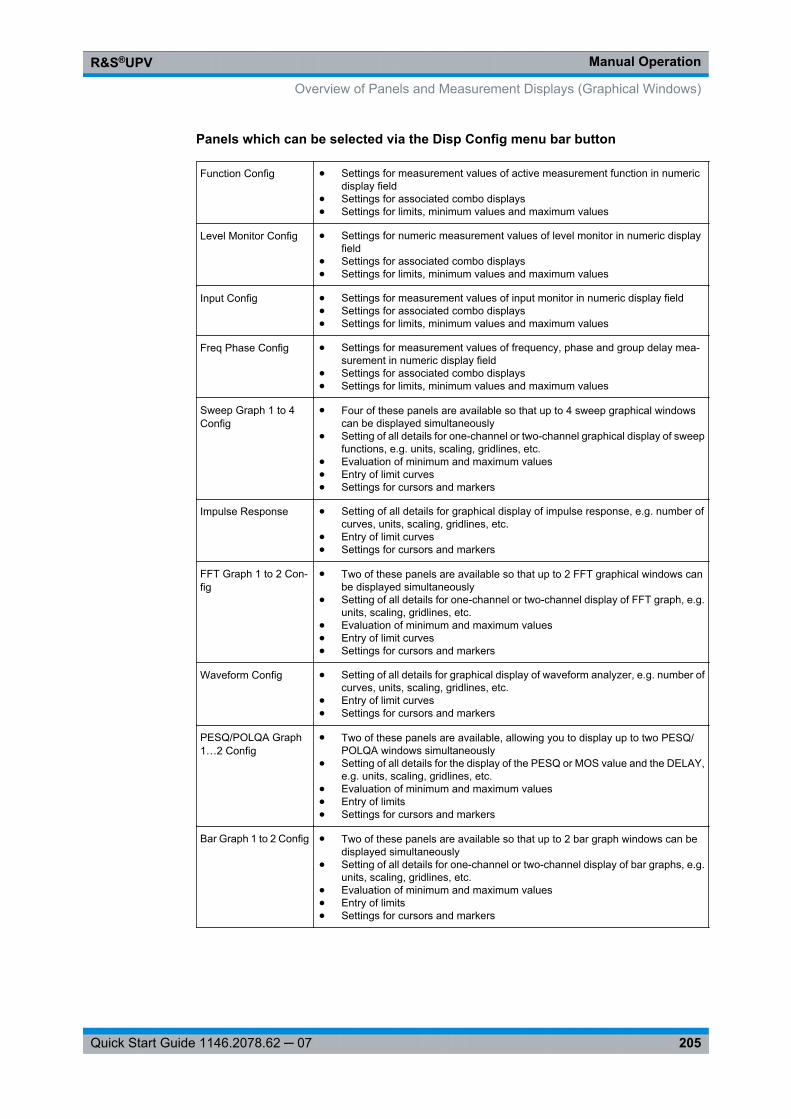
Manual OperationR&S®UPV
205Quick Start Guide 1146.2078.62 ─ 07
Panels which can be selected via the Disp Config menu bar button
Function Config ● Settings for measurement values of active measurement function in numericdisplay field
● Settings for associated combo displays● Settings for limits, minimum values and maximum values
Level Monitor Config ● Settings for numeric measurement values of level monitor in numeric displayfield
● Settings for associated combo displays● Settings for limits, minimum values and maximum values
Input Config ● Settings for measurement values of input monitor in numeric display field● Settings for associated combo displays● Settings for limits, minimum values and maximum values
Freq Phase Config ● Settings for measurement values of frequency, phase and group delay mea-surement in numeric display field
● Settings for associated combo displays● Settings for limits, minimum values and maximum values
Sweep Graph 1 to 4Config
● Four of these panels are available so that up to 4 sweep graphical windowscan be displayed simultaneously
● Setting of all details for one-channel or two-channel graphical display of sweepfunctions, e.g. units, scaling, gridlines, etc.
● Evaluation of minimum and maximum values● Entry of limit curves● Settings for cursors and markers
Impulse Response ● Setting of all details for graphical display of impulse response, e.g. number ofcurves, units, scaling, gridlines, etc.
● Entry of limit curves● Settings for cursors and markers
FFT Graph 1 to 2 Con-fig
● Two of these panels are available so that up to 2 FFT graphical windows canbe displayed simultaneously
● Setting of all details for one-channel or two-channel display of FFT graph, e.g.units, scaling, gridlines, etc.
● Evaluation of minimum and maximum values● Entry of limit curves● Settings for cursors and markers
Waveform Config ● Setting of all details for graphical display of waveform analyzer, e.g. number ofcurves, units, scaling, gridlines, etc.
● Entry of limit curves● Settings for cursors and markers
PESQ/POLQA Graph1…2 Config
● Two of these panels are available, allowing you to display up to two PESQ/POLQA windows simultaneously
● Setting of all details for the display of the PESQ or MOS value and the DELAY,e.g. units, scaling, gridlines, etc.
● Evaluation of minimum and maximum values● Entry of limits● Settings for cursors and markers
Bar Graph 1 to 2 Config ● Two of these panels are available so that up to 2 bar graph windows can bedisplayed simultaneously
● Setting of all details for one-channel or two-channel display of bar graphs, e.g.units, scaling, gridlines, etc.
● Evaluation of minimum and maximum values● Entry of limits● Settings for cursors and markers
Overview of Panels and Measurement Displays (Graphical Windows)
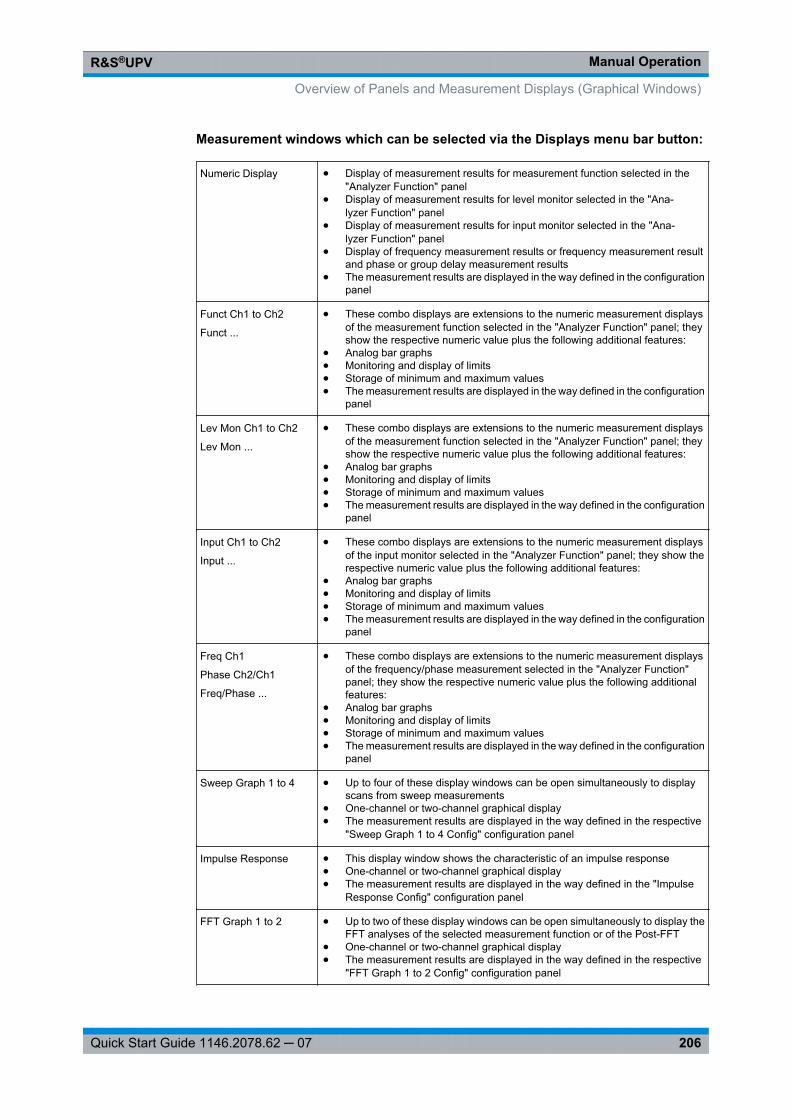
Manual OperationR&S®UPV
206Quick Start Guide 1146.2078.62 ─ 07
Measurement windows which can be selected via the Displays menu bar button:
Numeric Display ● Display of measurement results for measurement function selected in the"Analyzer Function" panel
● Display of measurement results for level monitor selected in the "Ana-lyzer Function" panel
● Display of measurement results for input monitor selected in the "Ana-lyzer Function" panel
● Display of frequency measurement results or frequency measurement resultand phase or group delay measurement results
● The measurement results are displayed in the way defined in the configurationpanel
Funct Ch1 to Ch2
Funct ...
● These combo displays are extensions to the numeric measurement displaysof the measurement function selected in the "Analyzer Function" panel; theyshow the respective numeric value plus the following additional features:
● Analog bar graphs● Monitoring and display of limits● Storage of minimum and maximum values● The measurement results are displayed in the way defined in the configuration
panel
Lev Mon Ch1 to Ch2
Lev Mon ...
● These combo displays are extensions to the numeric measurement displaysof the measurement function selected in the "Analyzer Function" panel; theyshow the respective numeric value plus the following additional features:
● Analog bar graphs● Monitoring and display of limits● Storage of minimum and maximum values● The measurement results are displayed in the way defined in the configuration
panel
Input Ch1 to Ch2
Input ...
● These combo displays are extensions to the numeric measurement displaysof the input monitor selected in the "Analyzer Function" panel; they show therespective numeric value plus the following additional features:
● Analog bar graphs● Monitoring and display of limits● Storage of minimum and maximum values● The measurement results are displayed in the way defined in the configuration
panel
Freq Ch1
Phase Ch2/Ch1
Freq/Phase ...
● These combo displays are extensions to the numeric measurement displaysof the frequency/phase measurement selected in the "Analyzer Function"panel; they show the respective numeric value plus the following additionalfeatures:
● Analog bar graphs● Monitoring and display of limits● Storage of minimum and maximum values● The measurement results are displayed in the way defined in the configuration
panel
Sweep Graph 1 to 4 ● Up to four of these display windows can be open simultaneously to displayscans from sweep measurements
● One-channel or two-channel graphical display● The measurement results are displayed in the way defined in the respective
"Sweep Graph 1 to 4 Config" configuration panel
Impulse Response ● This display window shows the characteristic of an impulse response● One-channel or two-channel graphical display● The measurement results are displayed in the way defined in the "Impulse
Response Config" configuration panel
FFT Graph 1 to 2 ● Up to two of these display windows can be open simultaneously to display theFFT analyses of the selected measurement function or of the Post-FFT
● One-channel or two-channel graphical display● The measurement results are displayed in the way defined in the respective
"FFT Graph 1 to 2 Config" configuration panel
Overview of Panels and Measurement Displays (Graphical Windows)
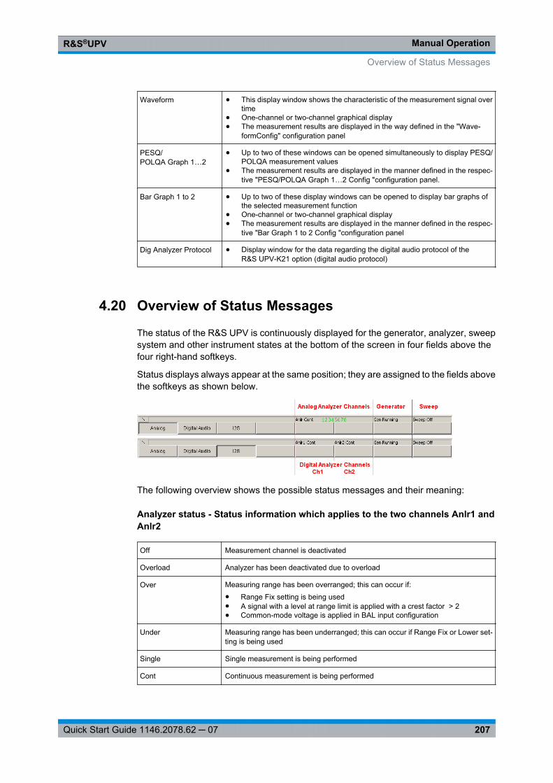
Manual OperationR&S®UPV
207Quick Start Guide 1146.2078.62 ─ 07
Waveform ● This display window shows the characteristic of the measurement signal overtime
● One-channel or two-channel graphical display● The measurement results are displayed in the way defined in the "Wave-
formConfig" configuration panel
PESQ/POLQA Graph 1…2
● Up to two of these windows can be opened simultaneously to display PESQ/POLQA measurement values
● The measurement results are displayed in the manner defined in the respec-tive "PESQ/POLQA Graph 1…2 Config "configuration panel.
Bar Graph 1 to 2 ● Up to two of these display windows can be opened to display bar graphs ofthe selected measurement function
● One-channel or two-channel graphical display● The measurement results are displayed in the manner defined in the respec-
tive "Bar Graph 1 to 2 Config "configuration panel
Dig Analyzer Protocol ● Display window for the data regarding the digital audio protocol of theR&S UPV-K21 option (digital audio protocol)
4.20 Overview of Status Messages
The status of the R&S UPV is continuously displayed for the generator, analyzer, sweepsystem and other instrument states at the bottom of the screen in four fields above thefour right-hand softkeys.
Status displays always appear at the same position; they are assigned to the fields abovethe softkeys as shown below.
The following overview shows the possible status messages and their meaning:
Analyzer status - Status information which applies to the two channels Anlr1 andAnlr2
Off Measurement channel is deactivated
Overload Analyzer has been deactivated due to overload
Over Measuring range has been overranged; this can occur if:● Range Fix setting is being used● A signal with a level at range limit is applied with a crest factor > 2● Common-mode voltage is applied in BAL input configuration
Under Measuring range has been underranged; this can occur if Range Fix or Lower set-ting is being used
Single Single measurement is being performed
Cont Continuous measurement is being performed
Overview of Status Messages
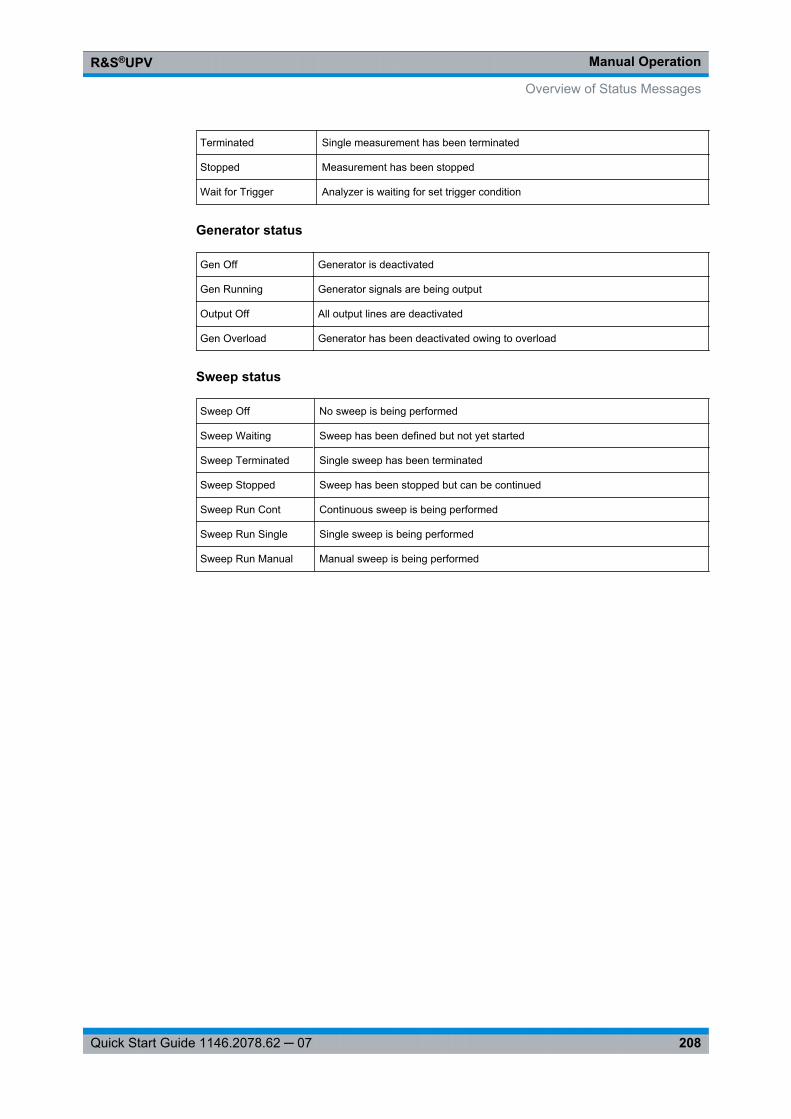
Manual OperationR&S®UPV
208Quick Start Guide 1146.2078.62 ─ 07
Terminated Single measurement has been terminated
Stopped Measurement has been stopped
Wait for Trigger Analyzer is waiting for set trigger condition
Generator status
Gen Off Generator is deactivated
Gen Running Generator signals are being output
Output Off All output lines are deactivated
Gen Overload Generator has been deactivated owing to overload
Sweep status
Sweep Off No sweep is being performed
Sweep Waiting Sweep has been defined but not yet started
Sweep Terminated Single sweep has been terminated
Sweep Stopped Sweep has been stopped but can be continued
Sweep Run Cont Continuous sweep is being performed
Sweep Run Single Single sweep is being performed
Sweep Run Manual Manual sweep is being performed
Overview of Status Messages
IndexR&S®UPV
209Quick Start Guide 1146.2078.62 ─ 07
Index
Symbols
19" rack ............................................................................ 26
A
AC supply ........................................................................ 27AC supply fuse ................................................................ 28Activate monitor .............................................................. 46Activate panel ................................................................ 127Analysis
with cursors ............................................................ 165with markers ............................................................ 165
Analyzer status .............................................................. 207Audio Monitor ................................................................ 183Auxiliaries panel ............................................................ 182Auxiliary analog output .................................................. 184
B
Backup ............................................................................ 65Bar Graph ...................................................................... 158BIOS version .................................................................... 29Booting ............................................................................ 29Brief introduction, operation ............................................ 74Button Sequence .................................................. 175, 178
C
Changing unit ................................................................ 140Clipping level .................................................................. 140Close All button .............................................................. 123Close panel .................................................................... 127Combined Display .......................................................... 149Combo fields setting ...................................................... 150Computer name .............................................................. 60Cont .............................................................................. 207Conversion formulas ...................................................... 194Conversion formulas for analog level measurement results
.......... 194Converting units ............................................................ 194
D
Data loss .......................................................................... 30DC Adjusting .................................................................. 207Device indicator .............................................................. 55DHCP networks .............................................................. 48Directories in the network ................................................ 52DispConfig button .......................................................... 177Display .......................................................................... 120Displays button ...................................................... 175, 178Display window .............................................................. 127
E
Edit button ...................................................................... 176Electrical discharges ........................................................ 24EMC protective measures ................................................ 24EN61010-1 ...................................................................... 27Entering the IP Address .................................................. 49Ethernet .......................................................................... 47Example
Measuring frequency response ................................ 87
Measuring harmonic distortion .................................. 99Example setups ............................................................ 107External keyboard ............................................................ 33External software ............................................................ 32
F
Factory Default setting .................................................... 67FFT Graph .................................................................... 156File button ...................................................................... 175File Extensions .............................................................. 192File Management .......................................................... 188File Select window ........................................................ 189Firewall ............................................................................ 47Firmware Update ............................................................ 64Fix All Sizes button ........................................................ 123Fix Size Auto Size button .............................................. 123Frequency response ...................................................... 140Full Screen button .......................................................... 123Functional testing ............................................................ 31Function level ................................................................ 113
G
Generator (low distortion) .............................................. 111Generator status ............................................................ 208Gen Off .......................................................................... 208Gen Overload ................................................................ 208Gen Running .................................................................. 208Getting Started ................................................................ 71Graphical window .......................................................... 154
H
Help button ............................................................ 175, 181Help System .................................................................. 185Help Text Language ...................................................... 187Help Texts
Language ................................................................ 187Hide panel ...................................................................... 127Horiz Size button ............................................................ 123Hum loops, avoiding ........................................................ 73
I
Input Help ................................................................ 83, 144Input level ...................................................................... 113Input voltage, permissible ................................................ 27Input voltages .................................................................. 16Instrument Concept ........................................................ 110Instrument feet ................................................................ 25Instruments button ........................................................ 176Instrument settings
/saving/loading ........................................................ 191Internal monitor will not be activated ................................ 46IP address ........................................................................ 60
K
KeyLAN RESET .............................................................. 30SHUTDOWN ............................................................ 30
Keyboard .......................................................................... 33
IndexR&S®UPV
210Quick Start Guide 1146.2078.62 ─ 07
L
LAN configurationPassword .................................................................. 56
LAN connection ................................................................ 47LAN LED .......................................................................... 55LED
LAN ............................................................................ 55SWITCH OFF ............................................................ 30
LoadInstrument settings .................................................. 191Traces ...................................................................... 165
Loading predefined instrument setups .......................... 107Low Distortion Generator .............................................. 111LXI (LAN eXtensions) ...................................................... 53LXI browser interface ...................................................... 56LXI website ...................................................................... 55
M
Manual Operation .......................................................... 109Manual Remote Operation ...................................... 60, 192Maximum output voltage .................................................. 72Measurement result display in numeric display field ............
148Measurement value display in lists ................................ 172Monitor
Connecting ................................................................ 33Monitor level .................................................................. 113Mouse .............................................................................. 33Moving graphical windows ............................................ 123Moving panels ................................................................ 123
N
Navigating in lists .......................................................... 173Negotiation ...................................................................... 58Network connector .......................................................... 47Network directories .......................................................... 52Next Bin ........................................................................ 169Next Peak ...................................................................... 168Next Pixel ...................................................................... 168Next Sample .................................................................. 169Next Step ...................................................................... 168Next Value .................................................................... 170
O
Open panel .................................................................... 127Operating Concept ........................................................ 109Operating examples ........................................................ 87Operation with mouse .................................................... 118Option
Installation ................................................................ 47Output Off ...................................................................... 208Output voltage, limiting .................................................... 72Over .............................................................................. 207Overload ........................................................................ 207Overview of Keys .......................................................... 200
P
PanelOverview .................................................................. 204
Panels ............................................................................ 127Parameter fields ............................................................ 128Password ........................................................................ 49
LAN configuration ...................................................... 56PC keyboard .................................................................. 119PESQ/POLQA Graph .................................................... 159Ping Client ........................................................................ 59Point-to-point connections .............................................. 49Power supply connection ................................................ 27Presets ............................................................................ 31
Q
Querying the computer name .......................................... 52
R
Rack Adapter .................................................................. 26Rack installation .............................................................. 24Rapid deactivation .......................................................... 72Rapid Deactivation of Outputs ...................................... 185Rated voltages ................................................................ 27Recovery .......................................................................... 65Reference values .......................................................... 140Remote control
Manual ...................................................................... 60Remote desktop .............................................................. 60Resizing graphical windows .......................................... 123Resizing panels .............................................................. 123Risk of overheating .......................................................... 26Rotary knob .................................................................... 118
S
Safety precautions .......................................................... 23Saving
Instrument settings .................................................. 191Traces ...................................................................... 165
Scaling graph ................................................................ 167Screen resolution ............................................................ 34Screens .......................................................................... 120Screens button .............................................................. 176Setting AC supply voltage ................................................ 28Settings in the Menu Bar ................................................ 175Settings in the Operating System .................................. 182Settings on the Toolbar .................................................. 181Shortcuts
Ctrl+Alt+Del .............................................................. 29Ctrl + Alt + F3 ............................................................ 46Ctrl + Alt + F4 ............................................................ 46
Single ............................................................................ 207Softkeys ........................................................................ 122Software lockup .............................................................. 29Splash screen .................................................................. 29Status displays .............................................................. 125Status messages .......................................................... 207Stopped .......................................................................... 207Sweep Graph ................................................................ 155Sweep Off ...................................................................... 208Sweep Run Cont ............................................................ 208Sweep Run Manual ........................................................ 208Sweep Run Single ........................................................ 208Sweep status ................................................................ 208Sweep Stopped .............................................................. 208Sweep Terminated ........................................................ 208Sweep Waiting .............................................................. 208Switching Off .................................................................... 30Switching on the instrument ............................................ 28System partition .............................................................. 67
IndexR&S®UPV
211Quick Start Guide 1146.2078.62 ─ 07
T
Terminated .................................................................... 207Title bar .......................................................................... 129Total load ........................................................................ 25Traces
Saving ...................................................................... 165showing and hiding .................................................. 166
Track Box ...................................................................... 144Trigger input .................................................................. 184Trigger output ................................................................ 184Trig In Out ...................................................................... 184
U
Under ............................................................................ 207Unit for digital phase measurement results (Phase to Ref) ...
..... 198Unit for S/N measurement results .................................. 196Unit of measurement result ............................................ 152Units .............................................................................. 194Units for digital jitter measurement results .................... 197Units for digital level measurement results .................... 195Units for distortion measurement results ...................... 196Units for frequency measurement results ...................... 196Units for group delay measurement results .................. 197Units for phase measurement results ............................ 197Units for Value Entries .................................................. 198Universal generator ........................................................ 110User ID ............................................................................ 49Utilities button ........................................................ 175, 179Utilities Config panel, General Configuration settings ..........
180
V
Valid value range .......................................................... 126Value range, permissible .............................................. 126Vert Move button ............................................................ 123Vert Size button ............................................................ 123Volume .......................................................................... 183Volume key .................................................................... 183VXI-11 Discovery ............................................................ 58
W
Wait for DC Adj .............................................................. 207Wait for Trigger .............................................................. 207Warm start ...................................................................... 29Warnings ........................................................................ 126Waveform ...................................................................... 157Windows button .................................................... 175, 181Windows XP .................................................................... 32Windows XP Recovery and Backup ................................ 65
X
X-axis ............................................................................ 165
Y
Y-axis ............................................................................ 162