Unidad docente de Electrónica y Automática - UPM · UNIVERSIDAD POLITÉCNICA DE MADRID...
35
UNIVERSIDAD POLITÉCNICA DE MADRID DEPARTAMENTO DE FÍSICA APLICADA E INGENIERÍA DE SISTEMAS Unidad docente de Electrónica y Automática LABORATORIO DE MECATRONICA Autor: Laurent Boisard Tutor: Carlos Platero Dueñas
Transcript of Unidad docente de Electrónica y Automática - UPM · UNIVERSIDAD POLITÉCNICA DE MADRID...

UNIVERSIDAD POLITÉCNICA DE MADRID
DEPARTAMENTO DE
FÍSICA APLICADA E
INGENIERÍA DE SISTEMAS
Unidad docente de Electrónicay Automática
LABORATORIODE
MECATRONICA
Autor: Laurent BoisardTutor: Carlos Platero Dueñas

Boisard Laurent Laboratory of Mecatronic
GCII-Fais-upm 2
Thanks,Thanks to Mr. Carlos Platero Dueñas who is my tutor to find me a stage subject
in the Polytechnic University of Madrid, and help me to succeed in my stage. And toMr. Colas, who is my teacher of English in the University of Toulon and the Var, whofind me this training course abroad which brought to me more things which I didn’tknow. And to Mr. Mario José Garcia of the international relation of the university ofMadrid who puts himself in contact with Mr. Martin Jacques who take care of theinternational relation in Toulon.

Boisard Laurent Laboratory of Mecatronic
GCII-Fais-upm 3
Boisard Laurent Laboratory of Mecatronic
GCII-Fais-upm 4
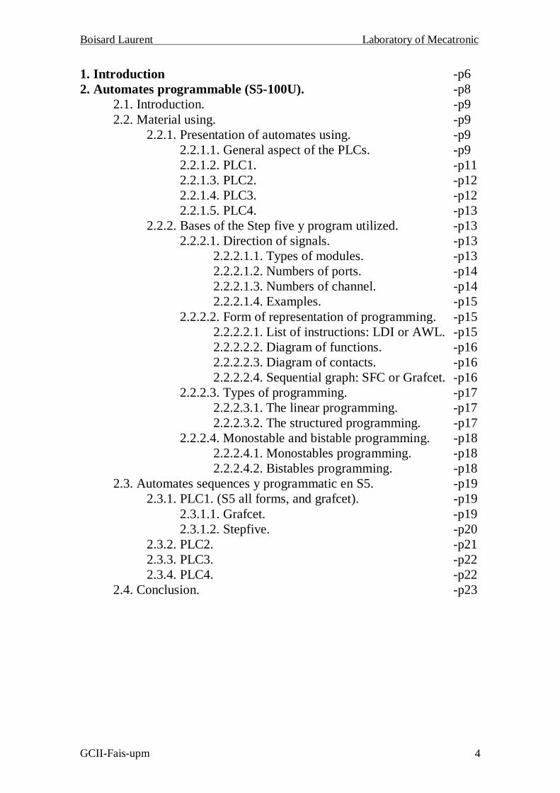
1. Introduction -p62. Automates programmable (S5-100U). -p8
2.1. Introduction. -p92.2. Material using. -p9
2.2.1. Presentation of automates using. -p92.2.1.1. General aspect of the PLCs. -p92.2.1.2. PLC1. -p112.2.1.3. PLC2. -p122.2.1.4. PLC3. -p122.2.1.5. PLC4. -p13
2.2.2. Bases of the Step five y program utilized. -p132.2.2.1. Direction of signals. -p13
2.2.2.1.1. Types of modules. -p132.2.2.1.2. Numbers of ports. -p142.2.2.1.3. Numbers of channel. -p142.2.2.1.4. Examples. -p15
2.2.2.2. Form of representation of programming. -p152.2.2.2.1. List of instructions: LDI or AWL. -p152.2.2.2.2. Diagram of functions. -p162.2.2.2.3. Diagram of contacts. -p162.2.2.2.4. Sequential graph: SFC or Grafcet. -p16
2.2.2.3. Types of programming. -p172.2.2.3.1. The linear programming. -p172.2.2.3.2. The structured programming. -p17
2.2.2.4. Monostable and bistable programming. -p182.2.2.4.1. Monostables programming. -p182.2.2.4.2. Bistables programming. -p18
2.3. Automates sequences y programmatic en S5. -p192.3.1. PLC1. (S5 all forms, and grafcet). -p19
2.3.1.1. Grafcet. -p192.3.1.2. Stepfive. -p20
2.3.2. PLC2. -p212.3.3. PLC3. -p222.3.4. PLC4. -p22
2.4. Conclusion. -p23
Boisard Laurent Laboratory of Mecatronic
GCII-Fais-upm 5
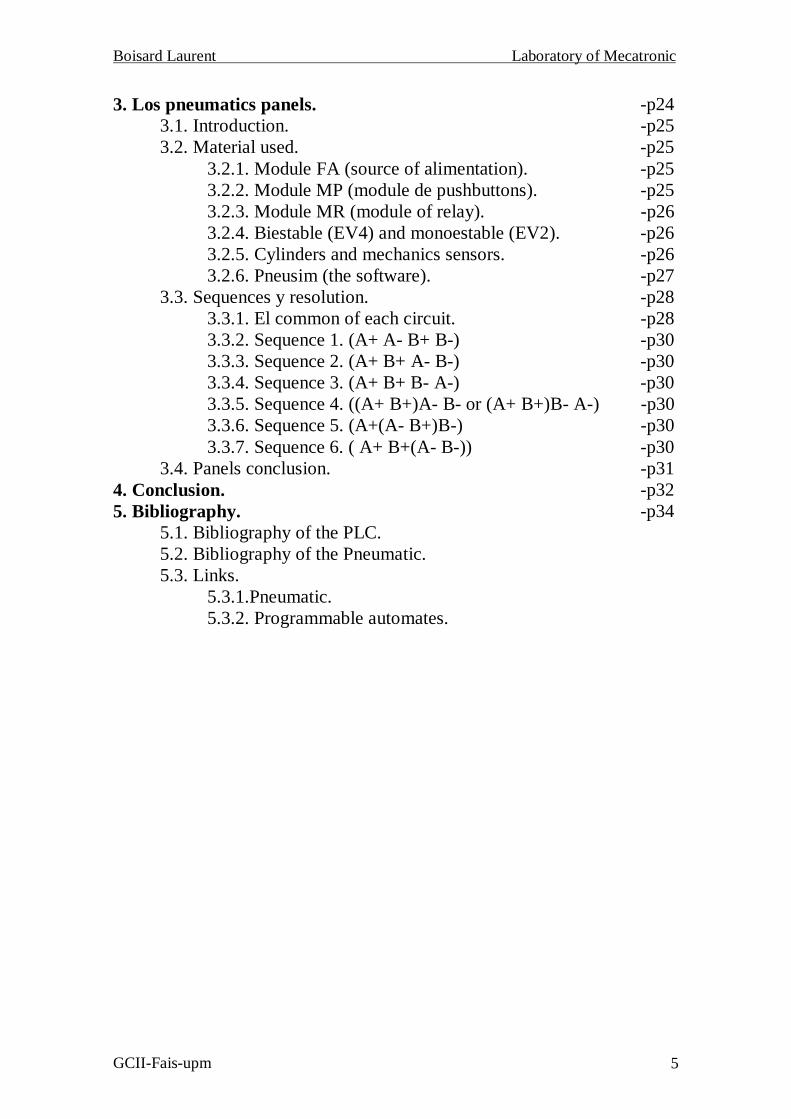
3. Los pneumatics panels. -p243.1. Introduction. -p253.2. Material used. -p25
3.2.1. Module FA (source of alimentation). -p253.2.2. Module MP (module de pushbuttons). -p253.2.3. Module MR (module of relay). -p263.2.4. Biestable (EV4) and monoestable (EV2). -p263.2.5. Cylinders and mechanics sensors. -p263.2.6. Pneusim (the software). -p27
3.3. Sequences y resolution. -p283.3.1. El common of each circuit. -p283.3.2. Sequence 1. (A+ A- B+ B-) -p303.3.3. Sequence 2. (A+ B+ A- B-) -p303.3.4. Sequence 3. (A+ B+ B- A-) -p303.3.5. Sequence 4. ((A+ B+)A- B- or (A+ B+)B- A-) -p303.3.6. Sequence 5. (A+(A- B+)B-) -p303.3.7. Sequence 6. ( A+ B+(A- B-)) -p30
3.4. Panels conclusion. -p314. Conclusion. -p325. Bibliography. -p34
5.1. Bibliography of the PLC.5.2. Bibliography of the Pneumatic.5.3. Links.
5.3.1.Pneumatic.5.3.2. Programmable automates.
Boisard Laurent Laboratory of Mecatronic
GCII-Fais-upm 6

Boisard Laurent Laboratory of Mecatronic
GCII-Fais-upm 7
The objective of this training course is to set up a new laboratory in thePolytechnic University of Madrid, in the department of F.A.I.S. « Fisica AplicadaIngeneria de Sistema ». This new laboratory will be called laboratory of« Mecatronic ».
This new laboratory will be composed of five pneumatics panels and fourpneumatics manipulators controlled by programmable automates.
The five pneumatics panels will be used in order to develop the pureselectropneumatics circuits (therefore with relays and contactors mechanical), and thefours manipulators will be used to develop electropneumatics circuits controlled bysome programmable automata.
It will be thus possible for us to thereafter carry out pneumatic circuits with acabled logic (pure circuits) or with a programmed logic (circuits controlled byprogrammable automates).
The Mecatronic is a a branch of engineering which try to combine the bestaspects of mechanics, electronics, computing and engineering of control to find optimalsolutions in the productions and the processes of manufacture.
Mecatronic is the union of bases, procedures and techniques for the service, ofthe production and development of the machines, and the devices and the installationdirected towards the future. The Mecatronic is thus an interdisciplinary technique builton the bases of mechanical, electric of engineering and electronics linked with dataprocessing and engineering of the « software ». The central goal is the integraldevelopment of systems of components (MECA), which must intelligently be controlled(TRONICA).

Boisard Laurent Laboratory of Mecatronic
GCII-Fais-upm 8

Boisard Laurent Laboratory of Mecatronic
GCII-Fais-upm 9
2.1. Introduction PLC:
The Industrial Programmable Automata is an electronic equipment, which couldbe programmed in a non-data-processing language to control, in real time and with theindustrial conditions, the sequential processes.
For this part of the project, we have to work out various programs for themanipulators, and carry out a preset sequence.
Each manipulator is different of an other, then we have to assimilate the outputsof the PLC (programmable logic controller) with the magnetic sensors in order to knowwhere the signal come from and the position of the manipulator. After that will comethe elaboration of the programs thanks to the software " StepFive ".
2.2. Material using.
2.2.1. Presentation of automates using.
2.2.1.1. General aspect of the PLCs.
The CPU: - A memory programmable(Programmable - Analog or numerical Input and OutputLogic Controller) - Control unit (Organizer)
- Timer- A meter interns- And memories independent
Comparison by a bus series to:
Peripheries: - Programmable automata- Timer- Meter- Comparator- Analog or numerical Input and Output

Boisard Laurent Laboratory of Mecatronic
GCII-Fais-upm 10
Representation of the PLC
Apron of command (They are all the same for all the PLC).
For the program, we use of the output of the manipulator like conditions and itsoutput to control the manipulator.
To make the contact easy between the manipulator and the PLC we use the“Apron of command”. By this way we could control the inputs of the PLC to simulatethe program.
All the Di are the outputs of the manipulator connect to the inputs of the PLC.And all the EVi are the outputs of the PLC connect to the inputs of the manipulator.
For each PLC, you can see which input of the PLC correspond to the output ofthe manipulator and then which input of the manipulator correspond to the output of thePLC.
Each Di is the representation of a sensor, then we use it for the program,transferred in the PLC, to know how the manipulator is and what it will do when itarrives to the place that we want.
This document represents the panel of sensors of the PLC2 (all the other PLCare represented on its left). The example of the PLC2 is important because we can seeall the possibility of inputs and outputs of a manipulator.
For this example, there is more possibility to explain because this manipulatoruses bistable and monostable valves to move.

Boisard Laurent Laboratory of Mecatronic
GCII-Fais-upm 11
Panel of sensors
Then we can see that the first part of the manipulator, which is controlled by abistable valve, could go to the left and then to the right and then to go to the left. Theinputs are EV1 and EV2.
It’s the same thing for the second part of the manipulator.(Go up and down)Contrary, the third and the fourth part are controlled by monostables valves.
Then there is only one input for each movement, and this input controls the twomovement of the manipulator. (Close and open the grip and turn the grip to the right andleft)
2.2.1.2. PLC1.
This manipulator is composed of four pneumatics cylinders, one horizontal, thesecond vertical, the third cylinder of rotation (right-left) and the last is a clamp thatopens and closes. Each cylinder takes two magnetic detectors of end of the direction.
The cylinders are controlled with four 4/2 monostables electrovalves.Assignation of the sensors:
D1 ---> Left cylinder horizontal ---> E32.1D2 ---> Right cylinder horizontal ---> E32.2D3 ---> On the top ---> E32.3D4 ---> On the bottom ---> E32.4D5 ---> Rotation to the left ---> E32.5D6 ---> Rotation to the right ---> E32.6D7 ---> Open the grip ---> E32.7D8 ---> Close the grip ---> E33.1
EV1 ---> Cylinder horizontal ---> A32.1EV2 ---> Cylinder vertical ---> A32.2EV3 ---> Rotation ---> A32.3EV4 ---> Grip ---> A32.4

Boisard Laurent Laboratory of Mecatronic
GCII-Fais-upm 12
2.2.1.3. PLC2.
This manipulator is constituted of four cylinders: one vertical, the secondhorizontal, the third cylinder of rotation and the last, which opens and closes the clamp.
The cylinders are controlled by two electrovalves monostables (rotation and clamp)and others two electrovalves bistables (cylinders horizontal and vertical) with tenmagnetic detectors of end of the direction.
Assignation of the sensors:
D1 ---> Left cylinder horizontal ---> E32.1D2 ---> Middle cylinder horizontal ---> E32.2D3 ---> Right cylinder horizontal ---> E32.3D4 ---> On the top ---> E32.4D5 ---> In the middle ---> E32.5D6 ---> On the bottom ---> E32.6D7 ---> Rotation to the right ---> E32.7D8 ---> Rotation to the left ---> E33.1D9 ---> Close the grip ---> E33.2D10 ---> Open the grip ---> E33.3
EV1 ---> Cylinder horizontal left ---> A32.1EV2 ---> Cylinder horizontal right ---> A32.2EV3 ---> Cylinder vertical top ---> A32.3EV4 ---> Cylinder vertical bottom ---> A32.4EV5 ---> Rotation ---> A32.5EV6 ---> Grip ---> A32.6
2.2.1.4. PLC3.
This manipulator is constituted of three pneumatics cylinders, one vertical, thesecond cylinder of rotation (right-left) and the last one which controls clamps whichopen and close. Each cylinder has two magnetic detectors of end of the direction.
The cylinders are controlled with three electrovalves 4/2 monostables.Assignation of the sensors:
D1 ---> On the top ---> E32.1D2 ---> On the bottom ---> E32.2D3 ---> To the right ---> E32.3D4 ---> To the left ---> E32.4D5 ---> Close the grip ---> E32.5D6 ---> Open the grip ---> E32.6
EV1 ---> Cylinder vertical ---> A32.1EV2 ---> Cylinder horizontal ---> A32.2EV3 ---> Grip ---> A32.3

Boisard Laurent Laboratory of Mecatronic
GCII-Fais-upm 13
2.2.1.5. PLC4.
This manipulator is constituted of three cylinders one horizontal, the secondvertical, and the last is a clamp that opens and closes controlled by one electrovalvemonostable and two electrovalves bistables with eight magnetic detectors of end of thedirection.
Assignation of the sensors:
D1 ---> Right cylinder horizontal ---> E32.1D2 ---> Middle cylinder horizontal ---> E32.2D3 ---> Left cylinder horizontal ---> E32.3D4 ---> On the top ---> E32.4D5 ---> In the middle ---> E32.5D6 ---> On the bottom ---> E32.6D7 ---> Open the grip ---> E32.7D8 ---> Close the grip ---> E33.1
EV1 ---> Cylinder horizontal left ---> A32.1EV2 ---> Cylinder horizontal right ---> A32.2EV3 ---> Cylinder vertical top ---> A32.3EV4 ---> Cylinder vertical bottom ---> A32.4EV5 ---> Grip ---> A32.5
2.2.2. Bases of the Step five and programming used.
2.2.2.1. The direction of the signals
The direction of the signals is defined by:
- Its abbreviation which is the type of connected module.- Its number of its connected port.- And its number of channel.
2.2.2.1.1.Types of modules.
- If it’s an Input module then its direction is "E".- If it’s an Output module then its direction is "A".

Boisard Laurent Laboratory of Mecatronic
GCII-Fais-upm 14
2.2.2.1.2. Number of port.
The number of its connected port:- Given number of 0 (on the right of the control unit) to 31.- Use until 16 elements of the bus- And connected until 32 modules.
2.2.2.1.3.The number of channel.
- If there is branch of a digital module of four channels then they are numbered from 0to 3. - If there is branch of a digital module of height channels then they are numbered from0 to 7.

Boisard Laurent Laboratory of Mecatronic
GCII-Fais-upm 15
2.2.2.1.4. Examples.
E1.0---> Input, connected port n° 1, and channel 0.A2.5---> Output, connected port n° 2, and channel 5.If direction of the signals doesn’t exist then we use "O".
We use Input called from E32.0 to E32.7 and from E33.0 to E33.7.And Output called from A32.0 to A32.7 and from A33.0 to A33.7.
The Input “E32.0” and “E33.0” are respectively kept for the “START” and the“EMERGENCY STOP”
2.2.2.2. Form of representation of the program:
2.2.2.2.1. List of instructions: LDI or AWL.
It is a low-level language similar to the assembly language with sentences.Single it allows an operation by line.
For example: U E 1.2UN E 1.3U E 1.4
ON E 1.5 O E 1.6
= A 2.5BE
The combinative operations:
- AND indicated by "U".- NAND indicated by "UN".- OR indicated by "O".- NOR indicated by "ON".
The memory operation:
- "S" which active an operand ("1" logic).- "R" which inibe an operand ("0" logic).
We can only put one instruction by line. And each instruction is doing one after theother.

Boisard Laurent Laboratory of Mecatronic
GCII-Fais-upm 16
2.2.2.2.2. Diagram of functions: FUP.
For example:
For this representation, we use logic doors.
2.2.2.2.3. Diagram of contacts: LD or KOP.
It consists of a symbolic programming very similar to the electrical diagrams.
For example:
2.2.2.2.4. Sequential graph (SFC or GRAFCET).
This program isn’t do with the software of StepFive but with Mediss.
It is a graphical language that provides a representation in form of diagram ofthe sequences of the program.

Boisard Laurent Laboratory of Mecatronic
GCII-Fais-upm 17
On the example, 0, 1 and 2 are the stages, EV1 and EV2 are the actions and D0,D1 and D2 are the transitions. Then when the transition is good it changes stage to dothe other action.
2.2.2.3. Types of programming.
There are two types of programming:
2.2.2.3.1. The linear programming.
- It’s cyclic.- It’s got a maximum of 1024 instructions.- It is not advised.
2.2.2.3.2. The structured programming.
- It’s cyclic too.- It is divided into several parts. (Modules ).

Boisard Laurent Laboratory of Mecatronic
GCII-Fais-upm 18
We will use the structured programming. In this programming we can use until16 modules.
There are several types of modules:- The organization modules like OB 1, OB 2, OB 3 . . .- The programs module from PB 0 to PB 255.- The function modules from FB 0 to FB 255.- And the modules of data from DB 2 to DB 255.
2.2.2.4. Monostable and bistable programming.
We will use different forms of programming, one for the monostable and otherone for the bistable.
2.2.2.4.1. Monostables programming.
For the programming of manipulators controlled by monostables valves, we usein the StepFive the “R” and the “S” which is memorial programming in order to put theinput of the valves to 24Volts that is “1 logic” and to 0Volt that is “0 logic”.
For example on the PLC1, if we want the manipulator to go to the right and thenstay there, we have to put EV1 (input of this manipulator for the horizontaldisplacement) to 24Volts. If EV1 go back to 0Volt, the manipulator will go back to itsinitial place. Then in order to keep the manipulator on the right EV1 has to stay at24Volts.
2.2.2.4.2. Bistables programming.
For the programming of manipulators controlled by bistables valves, we use inthe StepFive the standard form: the “=” then that put the input to 24Volts only for thetime when the condition are right.
For example on the PLC2, if we want the manipulator to go to the right and thenstay there, we have to put EV1 at 24Volts but only if it’s at the right place, if the sensorsof the arrival isn’t activated and then EV1 at 0Volts. Then when the manipulator will beat the right place then EV1 equalize 0Volt and the manipulator won’t move before EV2equalize 24Volts.

Boisard Laurent Laboratory of Mecatronic
GCII-Fais-upm 19
2.3. Automates sequences y programs en S5.
For the first automata, I will show two types of programming. For all theprograms we have to use all the movements of automates then all the in Input of themanipulator. Then, we use the fact that the program is cyclic in order to limit thenumber of segment.
2.3.1. PLC1. (S5, and grafcet).
Initialization: - Left, down, rotation to the right, grip open.
Sequence: - Go up, right horizontal, go down, close the grip, go up, left horizontal,turn, go down, open the grip, go up, turn, go down (initialization state)
2.3.1.1. Grafcet.

Boisard Laurent Laboratory of Mecatronic
GCII-Fais-upm 20
2.3.1.2. Step five.
Segment 1 Segment 2 Segment 3 Segment 4 Segment 5U –STARTU – D1U – D3U – D5U – D7S – EV4
U – D1U – D3U – D5U – D8S – EV1
O – STOPO (U – D2U – D3U – D6U – D7)R – EV1
U – D2U – D3U – D5U – D8O (U – D1U – D3U – D6U – D7)S – EV2
O – STOPO (U – D2U – D4U – D5U – D7)O (U – D1U – D4U – D6U – D8)R – EV2
Segment 6 Segment 7 Segment 8 Segment 9 Segment 10U – D2U – D3U – D5U – D7S – EV3
O – STOPU – D1U – D3U – D6U – D8R – EV3
O – STOPU – D2U – D4U – D5U – D8R – EV3
U – D1U – D4U – D6U – D7S – EV4
BE

Boisard Laurent Laboratory of Mecatronic
GCII-Fais-upm 21
2.3.2. PLC2.
Initialization: - Left, down, rotation to the right, grip open.
Sequence: - Go up, right horizontal, go down, close the grip, go up, left horizontal,turn, go down, open the grip, go up, turn, go down (initialization state)
Seg 1 Seg 2 Seg 3 Seg 4 Seg 5U – STARTU – D1U – D6U – D7U – D10O – EV3UN – D4O (U – D3U – D6U – D7U – D9O – EV3UN – D4)O (U – D1U – D6U – D8U – D10O – EV3UN – D4UN – STOP= – EV3
U – D1U – D4U – D7U – D10O – EV2UN – D3= – EV2
U – D3U – D4U – D7U – D10O – EV4UN – D6O (U – D1U – D4U – D8U – D9O – EV4UN – D6)O (U – D1U – D4U – D7U – D10O – EV4UN – D6UN – STOP= – EV4
U – D3U – D6U – D7U – D10S – EV6
U – D3U – D4U – D7U – D9O – EV1UN – D1= – EV1
Seg 6 Seg 7 Seg 8 Seg 9U – D1U – D4U – D7U – D9S – EV5
U – D1U – D6U – D8U – D9R – EV6
U – D1U – D4U – D8U – D10R – EV5
BE

Boisard Laurent Laboratory of Mecatronic
GCII-Fais-upm 22
2.3.3. PLC3.
Initialization: - Down, rotation to the right, grip open.
Sequence: - Go up, go down, close the grip, go up, turn, go down, open the grip, goup, turn, go down (initialization state)
Seg 1 Seg 2 Seg 3 Seg 4 Seg 5U – STARTU – D1U – D3U – D6S – EV1
U – D2U – D3U – D6S – EV3
U – D2U – D3U – D5O – STOPR – EV1
U – D1U – D3U – D5S – EV2
U – D1U – D4U – D5S – EV1
Seg 6 Seg 7 Seg 8 Seg 9U – D2U – D4U – D5O – STOPR – EV3
U – D2U – D4U – D6O – STOPR – EV1
U – D1U – D4U – D6O – STOPR – EV2
BE
2.3.4. PLC4.
Initialization: - left, down, grip open.
Sequence: - Go up, right horizontal, go down, close the grip, go up, left horizontal,go down, open the grip, go up, go down (initialization state)
Seg 1 Seg 2 Seg 3U – D3U – D5U – D7O (U – D2U – D6U – D7)S – EV5
U – D3U – D6U – D8O (U – D2U – D5U – D8)O – STOPS – EV5
U – D3U – D4U – D7O – EV4UN – D5O (U – D3U – D5U – D8O – EV4UN – D6)O (U – D2U – D4U – D7O – EV4UN – D6UN – STOP= – EV4

Boisard Laurent Laboratory of Mecatronic
GCII-Fais-upm 23
Seg 5 Seg 6 Seg 7U – D3U – D6U – D7O – EV3O (U – D2U – D5U – D7)O – EV3UN – D4)O (U – D2U – D6U – D8O – EV3UN – D5)UN – STOP= – EV3
U – D2U – D3U – D4U – D7O – EV1UN – D2O (U – D2U – D4U – D7O – EV1UN – D1UN – STOP= – EV1
BE
2.4. Conclusion PLC:
We have seen that some « parts » of the manipulators were controlled bymonostables valves and other by bistables valves, what have generated a change in the aprogrammatic. Thus for the monostables we use functions like « Set » and « Reset »which allow respectively to put the output of the PLC on 24 Volts or on 0 Volts, and forthe bistables, we only have to put the output on 24 Volts without put it back to 0 Volts.
The advantage of the use of the manipulator controlled by programmableautomata is because, for any sequence wanting to be carried out by the manipulator,none the connected cables change and thus only the program must be changed. Anotheradvantage it is that the programming of the automata can be carried out of a PC says« personal », and only one PC makes possible to program several automata bytransferring the program by a series bus from the PC the PLC.
The disadvantage of this use is the knowledge of the programming language, inorder to be able to program a sequence as fast as possible. Indeed the " StepFive " is aprogramming language, which doesn’t appear very complicated, but it is difficult tocontrol its subtleties in a few weeks.

Boisard Laurent Laboratory of Mecatronic
GCII-Fais-upm 24

Boisard Laurent Laboratory of Mecatronic
GCII-Fais-upm 25
3.1. Introduction pneumatic:
The pneumatic concept is about the phenomena and about the applications ofoverpressure or depression of the air. The majority of the pneumatic applications arebased on the use of overpressure.
For each panel, we have to do different sequences in order to see all thepossibility of wiring, and the modifications we have to do on each one to do othersequence.
For the realization of pneumatics and electropneumatics diagrams we use a« software » of the Norgren Martonair company, which work on this one which is aMSDOS software called « Pneusim ».
3.2. Material utilized.
3.2.1. Module FA (source of alimentation).
This module is the source of electric energy. Its tension of input is 220VA peakto peak, and its tension of output is 24Volts DC with a current of 1.3V.
3.2.2. Module MP (module de pushbuttons).
This module is composed of three pushbuttons, one red (used for the STOP), oneother green (used for the START) and the last orange (used for the emergency STOP).There are two contacts commutable by pushbutton and an indicator light by pushbutton.
The red pushbutton has got two positions one up and the other down butcontrary to the two other it stay in its position when we don’t push it. The green and theorange have got two positions too, but if we don’t push it, it will come back to its initialposition.
The indicator light and the push button function with 24VDC and a current of3A for the push button and 24mA for the indicator.

Boisard Laurent Laboratory of Mecatronic
GCII-Fais-upm 26
3.2.3. Module MR (module of relay).
This module is composed of three relays, which controlled each one fourcontacts. The relays have a LED in order to indicate if they are or they are not activate.When the relay is activated by the tension, the contacts that it controls change of place.
The indicator light and the push button function with 24VDC and a current of3A for the push button and 24mA for the indicator.
3.2.4. The pneumatic valves: Bistable (EV4) and monostable (EV2).
The pneumatic valves are those that govern the movement of the cylinders.There are two type of valves the monostable and the bistable.
- The monostable valve (EV2) has got only one current input then when thereis current, it send air by one of its air output and when there isn’t any current,it send air by the other air output.
- The bistable valve (EV4) has got two current input then when there is currentin one of them, it send air by one of its air output. And when there is currentin the other air input, it send air by the other air output. Then contrary to thebistable valve he could send air by the two air output in the same time and itcould send no air.
The pneumatics valves receive air of a compressor, which send air to all thevalves of the laboratory.
3.2.5. The pneumatic cylindersThe pneumatic cylinder is a device able to turn the contained energy into the
compressed air in mechanical work.
Boisard Laurent Laboratory of Mecatronic
GCII-Fais-upm 27
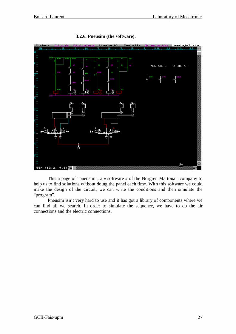
3.2.6. Pneusim (the software).
This a page of ”pneusim”, a « software » of the Norgren Martonair company tohelp us to find solutions without doing the panel each time. With this software we couldmake the design of the circuit, we can write the conditions and then simulate the“program”.
Pneusim isn’t very hard to use and it has got a library of components where wecan find all we search. In order to simulate the sequence, we have to do the airconnections and the electric connections.

Boisard Laurent Laboratory of Mecatronic
GCII-Fais-upm 28
3.3. Sequences y resolution.
3.3.1. The common of each circuit.
This is the START and the STOP, which are all the same for each panel. We useK0 because of the fact that if we don’t push the “Start Button” the sequence will stop. Ifwe don’t push the button, it will come back in its initial place and cut the alimentation.
Then K0 is used to keep current in the circuit, because when you push “StartButton” the contact K0 is connected until we push the Stop.
Boisard Laurent Laboratory of Mecatronic
GCII-Fais-upm 29
A0 A1 B0 B1
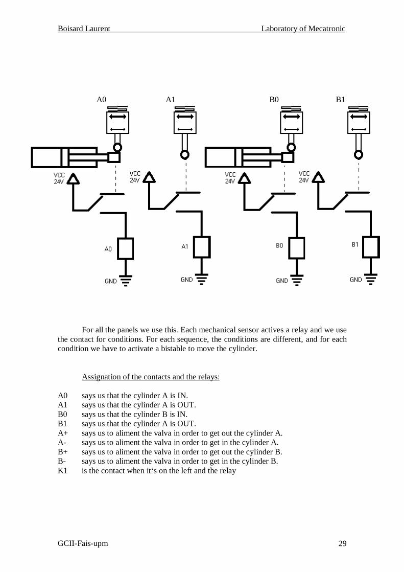
For all the panels we use this. Each mechanical sensor actives a relay and we usethe contact for conditions. For each sequence, the conditions are different, and for eachcondition we have to activate a bistable to move the cylinder.
Assignation of the contacts and the relays:
A0 says us that the cylinder A is IN.A1 says us that the cylinder A is OUT.B0 says us that the cylinder B is IN.B1 says us that the cylinder A is OUT.A+ says us to aliment the valva in order to get out the cylinder A.A- says us to aliment the valva in order to get in the cylinder A.B+ says us to aliment the valva in order to get out the cylinder B.B- says us to aliment the valva in order to get in the cylinder B.K1 is the contact when it‘s on the left and the relay

Boisard Laurent Laboratory of Mecatronic
GCII-Fais-upm 30
3.3.2. Sequence 1. (A+ A- B+ B-)
Sensors active Bistables (A+, A-, B+, B-), relays (K0, K1).
/E . A0 . B0. /K1 active A+ /E . A1 . B0 active A- /E . K1 . A0 . B0 active B+ /E . A0 . B1 active B- (A1 . B0) + (K1 . /B1) active K1
3.3.3. Sequence 2. (A+ B+ A- B-)
/E . A0 . B0 . K0 active A+ /E . A1 . B0 active B+ /E . A1 . B1 active A- /E . A0 . B1 active B-
3.3.4. Sequence 3. (A+ B+ B- A-)
/E . A0 . B0 . K0 active A+ /E . A1 . B0 . /K1 active B+ /E . A1 . B1 active B- /E . A1 . B0. K1 active A- (A1 . B1) + (K1 . /A0) active K1
3.3.5. Sequence 4. ((A+ B+) A- B- or (A+ B+) B- A-)
/E . A0 . B0 . K0 active A+ and B+/E . A1 . B1 active A- or B-
{ /E . A1 . B0 active A- {if B- before or { /E . A0 . B1 active B- {if A- before
3.3.6. Sequence 5. (A+(A- B+)B-)
/E . A0 . B0 . K0 active A+ /E . A1 . B0 active A- and B+ /E . A0 . B1 active B-
3.3.7. Sequence 6. (A+ B+(A- B-))
/E . A0 . B0 . K0 active A+ /E . A1 . B0 active B+ /E . A1 . B1 active A- and B-
For the sequence 1 and 3, we have to use a relay more because there were thesame conditions for two movements. Then the panel could do right the sequence.
Boisard Laurent Laboratory of Mecatronic
GCII-Fais-upm 31
3.4. Conclusion pneumatic:
Thus for the control of the cylinders we use only bistable valves (one bycylinders), which make it possible the cylinder to come out or re-enter sending pressureto them by one of its two inputs. The use of the mechanical sensors helps us to know theposition of the cylinder.
The advantages of this method are that there isn’t any programmatic language toknow, and that the software « Pneusim » is easier to use than StepFive. And contrary tothe manipulator controlled by programmable automates they need only an impulsion ofair to move until the end of movement. The manipulator controlled by programmableautomates need air until the end of the movement.
The disadvantage is that each sequence needs a different wiring, and then tochange the sequence we have to disconnect all the wire and then reconnect them.

Boisard Laurent Laboratory of Mecatronic
GCII-Fais-upm 32
Boisard Laurent Laboratory of Mecatronic
GCII-Fais-upm 33
The installation of the laboratory of Mecatronic allowed us to observe by thepractice, the difference between the pure circuit’s electropneumatic and theelectropneumatic circuits controlled by programmable automata. As well as we can seethe advantages and the disadvantages of each method.
These methods use the same base that is the utilization of the pneumatic to movethe automata. Then the fact that we use the air is normal for reason of price and use. Theair is clean and free, anywhere we go there is air around.

Boisard Laurent Laboratory of Mecatronic
GCII-Fais-upm 34

Boisard Laurent Laboratory of Mecatronic
GCII-Fais-upm 35
5.1. Bibliography of the PLC.
[Mand97] Enrique Mandado Pérez, Jorge Marcos Acevedo, Serafín Alfonso PérezLópez. Controladores lógicos y autómatas programables. Departament oftecnology electronic of the Vigo’s University . Ed. Marcombo, Boixareueditores, Barcelona, 1997.
[Balc92] Josep Balcells, José Luis Romeral. Autómatas programables. Serie MundoElectronic. Ed. Marcombo, Boixareu editores, Barcelona. 1992
5.2. Bibliography of the Pneumatic.
[Car80] Carnicer Royo, E. Aire comprimido. Neumática convencional. Ed.Paraninfo. Madrid. 1980
[Gui95] Guillen Salvador, Antonio. Automatización neumática y electroneumatica.Ed. Marcombo, Boixareu editores, Barcelona.1995
[Cemb99] Cembranos Nistal, Florencio J. “Automatismos eléctricos,neumáticos e hidráulicos”. Ed. Paraninfo. Madrid.1999
5.3. Links.
Eya.swin.net5.3.1. Pneumatic:
www.norgren.comwww.festo.comwww.smces.es
5.3.2. Programmable automates.
www.ad.siemens.dewww.modicom.eswww.omron.es