Serie UTBS - kaffe.gr manual.pdf · • Lea atentamente el contenido del presente libro de...
90
1 Serie UTBS Unidades de tratamiento de aire de bajo perfil Low-profile air-handling units Manual de instalación. Instrucciones de uso Installation manual. Instructions for use
Transcript of Serie UTBS - kaffe.gr manual.pdf · • Lea atentamente el contenido del presente libro de...

1
Serie UTBS
Unidades de tratamiento de aire de bajo perfil
Low-profile air-handling units
Manual de instalación. Instrucciones de uso Installation manual. Instructions for use

2
ES
PA
ÑO
L
ESPAÑOL
INDICE
1. GENERALIDADES . . . . . . . . . . . . . . . . . . . . . . . . . . . . . . . . . . . . . . . . . . . . . . . . . . . . . . . . . . . . . . . . . 32. NORMAS DE SEGURIDAD Y MARCADO “CE” . . . . . . . . . . . . . . . . . . . . . . . . . . . . . . . . . . . . . . . . . . . . . . . . . 33. NORMAS GENERALES . . . . . . . . . . . . . . . . . . . . . . . . . . . . . . . . . . . . . . . . . . . . . . . . . . . . . . . . . . . . . . . . . 34. ETIQUETADO DE LA UNIDAD . . . . . . . . . . . . . . . . . . . . . . . . . . . . . . . . . . . . . . . . . . . . . . . . . . . . . . . . . . . . . . . 45. MANIPULACIÓN . . . . . . . . . . . . . . . . . . . . . . . . . . . . . . . . . . . . . . . . . . . . . . . . . . . . . . . . . . . . . . . . . 56. INSTALACIÓN . . . . . . . . . . . . . . . . . . . . . . . . . . . . . . . . . . . . . . . . . . . . . . . . . . . . . . . . . . . . . . . . . 5 6.1. GENERALIDADES . . . . . . . . . . . . . . . . . . . . . . . . . . . . . . . . . . . . . . . . . . . . . . . . . . . . . . . . . . . . . . 5 6.2. IDENTIFICACIÓN DE PARTES DEL EQUIPO . . . . . . . . . . . . . . . . . . . . . . . . . . . . . . . . . . . . . . . . . . 6 6.3. LUGAR DE EMPLAZAMIENTO . . . . . . . . . . . . . . . . . . . . . . . . . . . . . . . . . . . . . . . . . . . . . . . . . . . . 6 6.4. ESPACIO PARA MANTENIMIENTO . . . . . . . . . . . . . . . . . . . . . . . . . . . . . . . . . . . . . . . . . . . . . . . . . 6 6.5. ENSAMBLAJE DE MÓDULOS . . . . . . . . . . . . . . . . . . . . . . . . . . . . . . . . . . . . . . . . . . . . . . . . . . . . . 8 6.5.1. UNIÓN DE TEJADILLOS . . . . . . . . . . . . . . . . . . . . . . . . . . . . . . . . . . . . . . . . . . . . . . . . 8 6.5.2. ENSAMBLAJE DE JUNTAS FLEXIBLES . . . . . . . . . . . . . . . . . . . . . . . . . . . . . . . . . . . . 9 6.5.3. ENSAMBLAJE DE UNIDADES EN PARALELO . . . . . . . . . . . . . . . . . . . . . . . . . . . . . . . 9 6.6. CONEXIÓN ELÉCTRICA DEL EQUIPO . . . . . . . . . . . . . . . . . . . . . . . . . . . . . . . . . . . . . . . . . . . . . 10 6.6.1. CONEXIÓN DE LOS MOTORES . . . . . . . . . . . . . . . . . . . . . . . . . . . . . . . . . . . . . . . . . 11 6.6.2. CONEXIÓN DE LA BATERÍA ELÉCTRICA . . . . . . . . . . . . . . . . . . . . . . . . . . . . . . . . . . 11 6.7. CONEXIÓN DE SENSORES DE PRESIÓN . . . . . . . . . . . . . . . . . . . . . . . . . . . . . . . . . . . . . . . . . . 16 6.7.1. ENSUCIAMIENTO DE FILTROS . . . . . . . . . . . . . . . . . . . . . . . . . . . . . . . . . . . . . . . . . . 16 6.7.2. CONTROL EN VENTILADORES . . . . . . . . . . . . . . . . . . . . . . . . . . . . . . . . . . . . . . . . . . . . . . . . . 16 6.7.2.1. CONEXIONADO DEL EQUIPO A PRESIÓN O CAUDAL CONSTANTE . . . . . . . . . . . 16 6.7.2.2. CONFIGURACIÓN DEL TRANSMISOR DE PRESIÓN DIFERENCIAL (TDP-S Y TDP-D) . . . . . . . . . . . . . . . . . . . . . . . . . . . . . . . . . . . . . . . . . . . . . . . . . . 18 6.7.2.2.1. MODELO TDP-S . . . . . . . . . . . . . . . . . . . . . . . . . . . . . . . . . . . . . . . . . . 18 6.7.2.2.2. MODELO TDP-D . . . . . . . . . . . . . . . . . . . . . . . . . . . . . . . . . . . . . . . . . . 19 6.7.2.2.3. CALIBRACIÓN DEL TRANSMISOR DE PRESIÓN (TDP-S Y TDP-D) . . 21 6.7.2.3. CONFIGURACIÓN DEL VARIADOR DE FRECUENCIA . . . . . . . . . . . . . . . . . . . . . . . 21 6.7.2.3.1. AJUSTE DEL PUNTO DE TRABAJO . . . . . . . . . . . . . . . . . . . . . . . . . . . 21 6.7.2.3.2. FUNCIONAMIENTO Y FALLOS . . . . . . . . . . . . . . . . . . . . . . . . . . . . . . . 22 6.7.2.3.3. RECONFIGURACIÓN DEL VARIADOR DE FRECUENCIA . . . . . . . . . . . 23 6.8. CONEXIÓN DEL EQUIPO A LA RED HIDRÁULICA . . . . . . . . . . . . . . . . . . . . . . . . . . . . . . . . . . . . 25 6.9. CONEXIÓN DEL EQUIPO A LA RED DE CONDUCTOS . . . . . . . . . . . . . . . . . . . . . . . . . . . . . . . . 26 6.10. RED DE DESAGÜE . . . . . . . . . . . . . . . . . . . . . . . . . . . . . . . . . . . . . . . . . . . . . . . . . . . . . . . . . . . 26 6.11. INSTALACIÓN DE CAJAS CON COMPUERTAS . . . . . . . . . . . . . . . . . . . . . . . . . . . . . . . . . . . . . 277. PROCEDIMIENTO DE PUESTA EN MARCHA . . . . . . . . . . . . . . . . . . . . . . . . . . . . . . . . . . . . . . . . . . . . . . . . . 278. OPERACIONES DE EMERGENCIA . . . . . . . . . . . . . . . . . . . . . . . . . . . . . . . . . . . . . . . . . . . . . . . . . . . . . . . . . 289. MANTENIMIENTO PREVENTIVO . . . . . . . . . . . . . . . . . . . . . . . . . . . . . . . . . . . . . . . . . . . . . . . . . . . . . . . . . . . 29 9.1. BATERÍAS DE INTERCAMBIO TÉRMICO . . . . . . . . . . . . . . . . . . . . . . . . . . . . . . . . . . . . . . . . . . . 29 9.2. RED DE DESAGÜE . . . . . . . . . . . . . . . . . . . . . . . . . . . . . . . . . . . . . . . . . . . . . . . . . . . . . . . . . . . . 29 9.3. MOTORES . . . . . . . . . . . . . . . . . . . . . . . . . . . . . . . . . . . . . . . . . . . . . . . . . . . . . . . . . . . . . . . . 29 9.4. VENTILADORES . . . . . . . . . . . . . . . . . . . . . . . . . . . . . . . . . . . . . . . . . . . . . . . . . . . . . . . . . . . . . . 30 9.5. FILTROS . . . . . . . . . . . . . . . . . . . . . . . . . . . . . . . . . . . . . . . . . . . . . . . . . . . . . . . . . . . . . . . . 30 9.5.1. SUSTITUCIÓN DE FILTRO EN EQUIPO PRINCIPAL Y RECUPERADOR PARALELO Y DE DOBLE ALTURA. . . . . . . . . . . . . . . . . . . . . . . . 30 9.5.2. SUSTITUCIÓN DE FILTROS EN RECUPERADORES EN LÍNEA . . . . . . . . . . . . . . . . . 31 9.6. BATERÍAS . . . . . . . . . . . . . . . . . . . . . . . . . . . . . . . . . . . . . . . . . . . . . . . . . . . . . . . . . . . . . . . . 31 9.7. COMPUERTAS . . . . . . . . . . . . . . . . . . . . . . . . . . . . . . . . . . . . . . . . . . . . . . . . . . . . . . . . . . . . . . . 31 9.8. SILENCIADOR . . . . . . . . . . . . . . . . . . . . . . . . . . . . . . . . . . . . . . . . . . . . . . . . . . . . . . . . . . . . . . . . 32 9.8.1. MÓDULO DE MEZCLAS . . . . . . . . . . . . . . . . . . . . . . . . . . . . . . . . . . . . . . . . . . . . . . . 32 9.8.2. CAJA DE MEZCLA 2 VÍAS CON BANCADA Y TEJADILLO . . . . . . . . . . . . . . . . . . . . . 33 9.9. HUMECTADOR . . . . . . . . . . . . . . . . . . . . . . . . . . . . . . . . . . . . . . . . . . . . . . . . . . . . . . . . . . . . . . . 33 9.10. RECUPERADOR . . . . . . . . . . . . . . . . . . . . . . . . . . . . . . . . . . . . . . . . . . . . . . . . . . . . . . . . . . . . . 3410. RECICLAJE . . . . . . . . . . . . . . . . . . . . . . . . . . . . . . . . . . . . . . . . . . . . . . . . . . . . . . . . . . . . . . . . 34

3
ES
PA
ÑO
L
1. GENEralIDaDEs
• Leagradecemoslaconfianzaquehadepositadoennosotrosmediantelacompradeesteaparato.Ustedhaadquiridounproductodecalidadquehasidototalmentefabricadose-gúnlasreglastécnicasdeseguridadreconocidasyconformesalasnormasdelaCE.
• Leaatentamenteelcontenidodelpresentelibrodeinstrucciones,puescontieneindicacio-nesimportantesparasuseguridaddurantelainstalación,elusoyelmantenimientodeesteproducto.Consérveloparaconsultasposteriores.
• Rogamoscompruebeelperfectoestadodelaparatoaldesembalarlo, yaquecualquierdefectodeorigenquepresenteestáamparadoporlagarantíaS&P.
• Elpersonalresponsabledelmontaje,delapuestaenmarchaydelmantenimiento,debeleerestasinstruccionesdeusoyfamiliarizarseconellasantesdeempezar.
2. NOrMas DE sEGUrIDaD Y MarCaDO “CE”
• LostécnicosdeS&Pestánfirmementecomprometidosconlainvestigaciónydesarrollodeproductoscadavezmáseficientesyquecumplanconlasnormasdeseguridadenvigor.
• Lasnormasyrecomendacionesqueseindicanacontinuación,reflejanlasnormasvigen-tes,preferentementeenmateriadeseguridadyporlotantosebasanprincipalmenteenelcumplimientode lasnormasdecaráctergeneral.Porconsiguiente,recomendamosatodaslaspersonasexpuestasariesgosqueseatenganescrupulosamentealasnormasdeprevencióndeaccidentesenvigorensupaís
• S&Pquedaexentodecualquierresponsabilidadporeventualesdañoscausadosaperso-nasyobjetosderivadosdelafaltadecumplimientodelasnormasdeseguridad,asícomodeposiblesmodificacionesenelproducto.ElselloCEylacorrespondientedeclaracióndeconformidad,atestiguanlaconformidadconlasnormascomunitariasaplicables.
3. NOrMas GENEralEs
• SeharealizadoelanálisisdelosriesgosdelproductocomoestáprevistoenlaDirectivadeMáquinas.Estemanualcontienelainformacióndestinadaatodoelpersonalexpuesto,conelfindeprevenirposiblesdañosapersonasy/oobjetosacausadeunadefectuosamanipulaciónomantenimiento.Todas las intervencionesdemantenimiento (correctivoypreventivo)debenserrealizadasconlamáquinaparadaylacorrienteeléctricadesconec-tada.
• Paraevitarelpeligrodeposiblearranqueaccidental,pongacartelesdeadvertenciaenelcuadroeléctricocentralyenlaconsoladecontrolconelsiguientemensaje:
”atención: control desconectado para operaciones de mantenimiento”
• Antesdeconectarelcabledealimentacióneléctricaalosmotores,verifiquequelatensióndelíneacorrespondealaindicadaenlaplacadecaracterísticasdelaunidad.
• Verifiqueperiódicamentelasetiquetasdelproducto.Siconelpasodeltiemposonilegibles,debensersustituidas.

4
ES
PA
ÑO
L
4. ETIQUETaDO DE la UNIDaD
• Launidadestáprovistadediversospictogramasdeseñalizaciónquenodebenserelimi-nados.Lasseñalessedividenen:
PICTOGraMa / ETIQUETa sIGNIfICaDO
Señalizacióndel registrodeaccesoalos ventiladores. Indica la obligatorie-daddedesconectarelequipoyespe-rar,pueshaypartesenmovimientoyexisteelpeligrodeengancharalgunapartedelcuerpo.
Indicación del sentido del aire en launidad.
Indicacióndeentradaysalidadelflui-dodelintercambiadortérmicodeaguafría.
Indicacióndeentradaysalidadelflui-dodelintercambiadortérmicodeaguacaliente.
Placadecaracterísticasde launidad.Enellaseindica-Modelo-Código-Númerodeserie-Añodefabricación-Potenciaútildemotoresinstalados-Intensidadmáximaabsolutadelmotor(A)-Potenciabateríaeléctricainstalada.-Alimentación

5
ES
PA
ÑO
L
5. MaNIPUlaCIÓN
• Alarecepcióndelequipo,sedesembalarálaunidadcomprobandolaintegridaddeésta,cualquierdesperfectopuedeserindicativodeundañoenelequipo.Serepasaráycom-probaráquenofalteningúnelemento.
• Silaunidadpresentaalgúndañooelenvíonoescompleto,anotarlasincidenciasenelalbarándeentregayenviarunareclamaciónalacompañíaquerealizóelenvío.AsimismohacerconstarcualquierincidenciaaS&P.
• Elclimatizadorsesuministradivididoenmódulos.Eltrasladodecadaunodelosmóduloshastasulugardeimplantacióndefinitivasolopodrárealizarseenlaposicióndemontajesalvoautorizaciónexpresadelfabricante.
• Losaparatossedeberántransportarconcorreasdeelevación.Elequipoposeeunascan-tonerasagujereadasparasucargaydescarga.
6. INsTalaCIÓN
6.1. GENEralIDaDEs
• Elempleadoencargadodelarecepcióndelequipodeberáasegurarsequelascaracterís-ticasdelsuministroeléctricodisponibleestándeacuerdoconlosdatoseléctricosquehayenlaplacadecaracterísticasdelaunidad.
• Antesdeimplantarelequipoensulugardefinitivo,secomprobaráqueellugardondesevaaubicarelequipoeslosuficientementeresistentecomoparapodersoportarelpesodeéste.
• Noseinstalaránestosequipos,bajoningúnconcepto,enentornosinflamablesoexplosi-vos,enentornoscargadosdevaporesdeaceite,deairesalinoocorrosivos.
• Lainstalacióndelosequipospuedeserpeligrosa,debidoalmaterialusado,alaspresionesenelsistemaya loscomponenteseléctricos.Esporelloquesólopersonaldeservicioentrenadoycualificadodebeinstalar,servirorepararlosequipos.
• Setendrálaprecaución,cuandosehaganoperacionesenelinteriordelequipo,deinte-rrumpirlacorrienteeléctricaenelseccionadorprincipal,paraimpedirlosposiblesacciden-tesconlaspartesmóvilesdelequipoquepuedanponerseenmarchaimprevisiblemente,asícomoparaimpediruncontactodirectooindirectoconcualquierparteactiva.
• Enlainstalacióndelequiposedeberánivelarparaunbuenajustedelosdiferentesmódu-los,unperfectoevacuadodecondensadosyunabuenaaperturadelosregistros.
• Paracomprobarelperfectoestadodelventiladorserevisaráelcentradodelarodeaspira-ciónhaciendogirarlaturbinaamano.

6
ES
PA
ÑO
L
6.2. IDENTIfICaCIÓN DE ParTEs DEl EQUIPO
Elmóduloprincipalpuedeestarcompuestoportresseccionesdiferenciadas:filtro,bateríasyventiladores,pudiendonoestaralgunadelasdosprimeras.Enlafigurasiguienteseidentifi-canloscomponentesprincipalesdelmóduloprincipal.
6.3. lUGar DE EMPlaZaMIENTO
• Evitar la instalacióndelaparatoenzonaspróximasafuentesdecaloryzonashúmedasdóndelaunidadpuedaentrarencontactoconelagua.
• Seaconsejaemplazarlaunidadenunaubicacióndóndelainstalaciónseadefácilacceso.Preverunespaciosuficienteparaelmantenimiento,elconexionadoy laevacuacióndecondensados.
6.4. EsPaCIO Para MaNTENIMIENTO
• Elinstaladordebepreverunosespacioslibresdeobstrucciónypoderaccederlibrementealaparatoparasumantenimiento.Elespaciorequeridodependerádelladodelaunidaddóndesehagalaextracción.Elequipoestáprovistodeunosregistroslateralesparapoderaccederalosfiltrosoalosventiladores.Paraextraerlasbateríassedebesacarelpanellateral.Tantolosfiltroscomolosventiladoressepuedenextraerporcualquierladodelaunidad.

7
ES
PA
ÑO
L
Modelo A (mm) B (mm)
UTBS-2 750 360
UTBS-3 1100 410
UTBS-5 1500 410
UTBS-8 1900 500
• Paraelmontajeentechoysuelo,sedeberásuspenderdelascuatroescuadrasexistentesencadamódulocomosigue:
MONTAJEENTECHOMONTAJEENSUELO
aTENCIÓN! Debido a la longitud y el peso de los aparatos, se deberá suspender cada módulo por separado.

8
ES
PA
ÑO
L
Ningúnobstáculodeberáimpediroreducirelpasodeaireenaspiración.
POSICIÓNMONTAJE
6.5. ENsaMBlaJE DE MÓDUlOs
Losbastidoresdelosmódulosdisponendeescuadrasenlascuatroesquinascuyafuncióneslasujecióndelequipoaltechoylasujecióndediferentesmódulosentresi.Sielequipoestáformadopordiferentesmódulossesuministraráunkitdeunióncompuestopor4juegosdetornillos,arandelas,tuercasyjuntadeestanqueidad.
6.5.1. UNIÓN DE TEJaDIllOs
Sihapedidounclimatizadorparairalaintemperie,elequipollevaráincorporadountejadilloanti-lluvia.Encasoqueelclimatizadorestéformadoporunoomásmódulos,launióndelostejadillossedeberárealizarponiendomasillaenlasuniones,cómoindicalafigura:

9
ES
PA
ÑO
L
6.5.2. ENsaMBlaJE DE JUNTas flEXIBlEs
Sihapedido juntasflexiblesen las terminacionesde lasunidades,se lesuministraránporseparado.
6.5.3. ENsaMBlaJE DE UNIDaDEs EN ParalElO
Cuándosehayanpedidoequiposparainstalarenparalelo,enelcasodetenermódulorecu-peradoromódulofree-cooling,elequipovendráprovistodeescuadrasparaunirlosmódulos.Parafijardichasescuadrassedeberáaccederalequipoporelinterior:
- Situarlaescuadrasobreelperfildealuminioyatornillarcondostornillosautotala-drantes(1)
- Colocarburlete(2)- Procederalaunióndelosmódulosfijandolasdosescuadrasmedianteuntornillo
M8,arandelasyunatuerca(3)

10
ES
PA
ÑO
L
Ejemplo de unión de módulos en paralelo:
6.6. CONEXIÓN ElÉCTrICa DEl EQUIPO
• Lainstalacióndebeserrealizadaporpersonalcalificado.
• Seinstalaráncablescuyaseccióncumplalasdirectivasactualeseimpidanuncalentamien-todeéstosyunacaídadetensiónsuperioralapermitida.Secumplirálanormativavigenteyentodomomentoseseguiránloscriteriosdelproyectista.
• Antesderealizarlaconexióndeloscables,secomprobaráquelainstalacióneléctricaestédesconectadayquenohayatensiónentreloscables.
• Unavezinstalado,elaparatodebecumplirconlasDirectivassiguientes:-DirectivadeBajaTension2006/95/CE-DirectivadeMáquinas2006/42/CE-DirectivadeCompatibilidadElectromegnética2004/108/CE
• Realizadasestasoperacioneshayqueverificarelaprietedetodaslasconexioneseléctri-cas(uncablemalapretadopuedeocasionardañosirreparables).
• Verificarquelapuestaatierrasehaefectuadocorrectamenteyquelasproteccionestér-micasydesobre-intensidadhansidoreguladasconformealosvaloresestablecidosenlaplacadecaracterísticas.
• Comomedidadeseguridadsielventiladorsequedarasintensiónsedeberánrealizarlosenclavamientosnecesariosparaque todos losdemáselementoseléctricosquedensintensión.

11
ES
PA
ÑO
L
6.6.1. CONEXIÓN DE lOs MOTOrEs
• Pararealizarelconexionadodelosmotores:- Enlosequiposlacajadeconexionesdelosmotoresestáorientadahaciaellado
delregistrodeinspecciónparafacilitarsuacceso.
• Pasarlamangueraporlospasacablesinstaladosenlaunidad:
6.6.2. CONEXIÓN DE la BaTErÍa ElÉCTrICa
• Utilizarlabateríaeléctricaúnicamentepararecalentarelairelimpio.Elensuciamientodelasresistenciaseléctricasaumentaelriesgodeincendio.Serecomiendalautilizacióndeunfiltrodeaireencimadelabatería.
• Laconexióneléctricadeberápreverundispositivodecontroldelcaudaldeaire.Labateríadeberáponerseenmarchacuandosealcanceelcaudaldeairemínimoobiencuandolavelocidaddelairedentrodelabateríaseasuperiora1,5m/s.
• Lainstalacióneléctricanodebepermitirquesepuedaponerenmarchalabateríasielven-tiladorestáparado.Labateríaeléctricadebeponerseenmarchadespuésobienalmismotiempoqueelventilador.
• Lainstalacióneléctricanodebepermitirquesepuedapararelventiladorcuandolabateríaestéenfuncionamiento.Elventiladordebepermanecerparadodespuésdelparoyelen-friamientodelabatería.
• Notocarlabateríaeléctricacuandoestéenfuncionamiento.
• Encasodequeunodelosdispositivosdeproteccióneléctricadelainstalaciónseaccio-nara,desenchufarelaparatoyverificarlainstalaciónantesdeponerlaenmarchadenuevo.

12
ES
PA
ÑO
L
Enelesquemaadjuntosemuestracomoconectarlasresistenciasdelabateríaeléctrica:
Conexionado electrico BE-2 15 kw 1 etapa catalogo
Conexionado electrico BE-2 7,5 kw 2 etapas catalogo

13
ES
PA
ÑO
L
Conexionado electrico BE-3 24 kw 1 etapa catalogo
Conexionado electrico BE-3 24 kw 2 etapas catalogo

14
ES
PA
ÑO
L
Conexionado electrico BE-5 18 kw 2 etapas catalogo
Conexionado electrico BE-5 12 kw 3 etapas catalogo

15
ES
PA
ÑO
L
Conexionado electrico BE-8 22,5 kw 2 etapas catalogo
Conexionado electrico BE-8 15 kw 3 etapas catalogo

16
ES
PA
ÑO
L
6.7. CONEXIÓN DE sENsOrEs DE PrEsIÓN
6.7.1. ENsUCIaMIENTO DE fIlTrOs
Paracontrolarelensuciamientodelosfiltroselequipodisponede2tomasdepresiónacadaladodelosfiltrosconelfindeconectarunpresostato.Enelapartado9.5.semuestraunatablaconlosvaloresrecomendadosparalasustitucióndelosfiltros.
6.7.2. CONTrOl EN VENTIlaDOrEs
• Elequipodisponede3tomasdepresiónparacontrolarelventiladoracaudalconstanteoapresiónconstante.Pararealizaruncontrolacaudalconstanteesnecesariointroducirelvalor“K”delasiguientetabla:
UTBS-2 K=69
UTBS-3 K=84
UTBS-5 K=84
UTBS-8 K=104
6.7.2.1 CONEXIONaDO DEl EQUIPO a PrEsIÓN O CaUDal CONsTaNTE

17
ES
PA
ÑO
L
• Comprobarqueelinterruptor“SW1”delvariadordefrecuenciaestáenlaposiciónSOURCE.
ATENCIÓN: cuando se utilice un único variador de frecuencia para controlar dos motores los protectores térmicos se conectarán en serie.
6.7.2.2 CONfIGUraCIÓN DEl TraNsMIsOr DE PrEsIÓN DIfErENCIal (TDP-s Y TDP-D)
• Sisedeseaconfigurarelequipopararealizaruncontrolapresiónconstantepuedenem-plearselosmodelosdetransmisordepresióndiferencialTDP-SyTDP-D.SisedeseallevaracabouncontrolacaudalconstanteúnicamentesepuedeutilizarelmodeloTDP-D.
Elconexionadodelostubosdepresióndependerádeltipodecontrolrequerido,talycomosemuestraenlasiguientefigura

18
ES
PA
ÑO
L
Importante:eltubodepresiónmásaltatienequeconectarsealterminal“+”yeldepresiónmásbajaal“-“.Encasodenorealizarsedeestamaneralapresiónmedidaestaráfueraderangoylapantalladeltransmisorparpadeará.
6.7.2.2.1 MODElO TDP-s

19
ES
PA
ÑO
L
fUNCIONaMIENTO a PrEsIÓN CONsTaNTE
• Situareljumperdetiposeñaldesalidadeltrasmisor(mA/V)enlaposicióndevoltaje(con-figuracióndefábrica).
• ConfigurarelmicrointerruptorDIPtalycomoseindicaenlastablassiguientes.Laselec-cióndelrangodepresióndeseadoserealizamediantelosinterruptoresDIP1,DIP2yDIP3.
Rango de presión (Pa) DIP 1 DIP 2 DIP 3
-50...+50 1 1 1
0...+100 0 1 1
0...+150 1 0 1
0...+300 0 0 1
0...+500 1 1 0
0...+1000 0 1 0
0...+1600 1 0 0
0...+2500 0 0 0
Micro interruptor DIP 4/5/6 ON / OFF Observaciones
DIP 4 - No utilizado
DIP 5 Seleccionar en función del tiempo de amorti-guación deseado: 0,4s (OFF) / 10s (ON)
DIP 6 OFF Voltaje de salida mínimo 0V
6.7.2.2.2 MODElO TDP-D

20
ES
PA
ÑO
L
fUNCIONaMIENTO a PrEsIÓN CONsTaNTE
• Situareljumperdetiposeñaldesalidadeltrasmisor(mA/V)enlaposicióndevoltaje(con-figuracióndefábrica).
•ConfigurarelmicrointerruptorDIPtalycomoseindicaenlasiguientetabla:
Micro interruptor DIP ON / OFF Observaciones
DIP 1 - No utilizado
DIP 2 - No utilizado
DIP 3 - No utilizado
DIP 4 OFF Modo presión (Pa)
DIP 5 Seleccionar en función del tiempo de amortiguación deseado: 0,4s (OFF) / 10s (ON)
DIP 6 OFF Voltaje de salida mínimo 0V
•Ajustarelrangodepresión:paraellopulseelbotónde“OK”ydesplácesealrangodeseadomediantelosbotones“”y“”.Finalmentevuelvaapulsar“OK”paraguardarlaconfigu-ración.Losrangosdepresiónseleccionablessonlossiguientes:-50...+50Pa;0...+100Pa;0...+150Pa;0...+300Pa;0...+500Pa;0...+1000Pa;0...+1600Pa;0...+2500Pa.
fUNCIONaMIENTO a CaUDal CONsTaNTE
DisponibleúnicamenteenelmodeloTDP-D.Enestemododefuncionamientoeltransmisordepresiónconviertelapresióndiferencial(∆P)acaudal(qv)mediantelasiguienteecuación:
qv=k √∆P
• Situareljumperdetiposeñaldesalidadeltrasmisor(mA/V)enlaposicióndevoltaje(con-figuracióndefábrica).
•ConfigurarelmicrointerruptorDIPtalycomoseindicaenlasiguientetabla:
Micro interruptor DIP ON / OFF Observaciones
DIP 1 - No utilizado
DIP 2 - No utilizado
DIP 3 - No utilizado
DIP 4 ON Modo caudal
DIP 5 Seleccionar en función del tiempo de amortiguación deseado: 0,4s (OFF) / 10s (ON)
DIP 6 OFF Voltaje de salida mínimo 0V

21
ES
PA
ÑO
L
•Ajustarelrangodecaudalyelparámetrok:pulsandoelbotón“OK”seaccedeenprimerlugaralaseleccióndelrangodecaudal.Pulsándolonuevamentesevaaccediendounoaunoalosdistintosdígitosdelparámetrok,conlaposibilidaddeelegironoundecimal.Mediantelosbotones“”y“”seajustanlosvaloresdeseados.Finalmentevolviendoapulsar“OK”seguardalaconfiguraciónysesaledelmenúdeajuste.Losrangosdecaudalselecciona-blessonlossiguientes:100m3/h;300m3/h;500m3/h;1000m3/h;3000m3/h;5000m3/h;9999m3/h;30m3/hx1000;50m3/hx1000;99,99m3/hx1000.Lasunidadesm3/hpuedenreemplazarseporl/s.
•Pegarlaetiquetaadhesivacorrespondientealaunidaddemedidaempleadaenelparáme-trok(m3/h,l/s,m3/hx1000,l/sx1000).
6.7.2.2.3 CalIBraCIÓN DEl TraNsMIsOr DE PrEsIÓN (TDP-s Y TDP-D)
Unavezrealizadotodoelconexionadoserecomiendaefectuaruncalibradoacero.Trasen-cenderelequipo(seiluminaelLEDverde)espereunosinstantesaqueeltransmisoralcancela temperaturade funcionamientousual.Acontinuaciónpulseelbotóndepuestaacero.ElLEDamarilloparpadearáhastaquefinaliceelprocesodecalibración.Parallevaracabocorrectamentelacalibraciónlapresiónenlosterminales+y–hadeserlamisma.Sereco-miendaquelostubosesténdesconectados.
6.7.2.3 CONfIGUraCIÓN DEl VarIaDOr DE frECUENCIa
Elvariadordefrecuenciavienepre-configuradoporS&Ppararealizaruncontrolapresiónocaudalconstante,yelúnicoajustequeesnecesariorealizaresconfigurarlafrecuenciadelpuntodetrabajodelequipo.
6.7.2.3.1 aJUsTE DEl PUNTO DE TraBaJO
Elrangodefrecuenciasdefuncionamientoestáprefijadopordefectoentre20Hzy50Hz.Enalgunassituacioneselpuntodetrabajorequiereunafrecuenciadesalidasuperiora50Hz,porloqueseránecesarioreconfiguraresteparámetro.El reajuste es únicamente necesario si la frecuencia del punto de trabajo es superior a 50Hz,nosiéndolocuandoesinferior.Este dato puede encontrarlo en la hoja de selección del equipoycorrespondealpunto de operación máximodelsistema.Paraajustarloprocedacomosedetallaacontinuación.Paradesplazarseentrelosdiferentesmenúsyentrelosvaloresdeunparámetrodentrodeunmenúgirar la rueda.Paraaccederaunmenúdeterminadoyparaseleccionarel valordeunparámetropulse“ENT”.Pararetrocederalmenúanteriorosalirdelaseleccióndeunparámetropulse“ESC”.

22
ES
PA
ÑO
L
Enprimerlugarentreenmodoprogramación.Elvariadordisponededosmodosdefunciona-miento,RUNyPROGRAMACIÓN.ParapasardeunoaotroesnecesariopulsarESCdurantedossegundos.
• PulseESCdurantedos segundoshastaque los leds indicadoresdemodoparpadeensimultáneamente.
Acontinuacióndesbloqueeelvariador:• Pulse“ENT”ygirelaruedahastallegaralmenú“SUP-“• Pulse“ENT”ygirelaruedahastaelparámetro“COd”• Pulse“ENT”ygirelaruedahastaqueaparezca“1951”• Pulse“ENT”ygirelaruedahastaqueaparezca“OFF”• Pulse“ENT”yvuelvaalmenúprincipalpulsandodosveces“ESC”Verifiquesielvalordelparámetro“tFr”delmenú“drC”es igualomayorqueelvalorde lafrecuenciadelpuntodetrabajodelequipo.Denoserasí,modifiqueésteparámetroconunvalorigualosuperioraldelpuntodetrabajodelequipo:• Pulse“ENT”ygirelaruedahastallegaralmenú“drC-“• Pulse“ENT”ygirelaruedahastaelparámetro“tFr”• Pulse“ENT”ygirelaruedahastaunvalorigualosuperioraldelafrecuenciadetrabajodel
equipo• Pulse“ENT”yvuelvaalmenúprincipalpulsandodosveces“ESC”
Acontinuaciónintroduzcaelvalordelafrecuenciadelpuntodetrabajodelequipoenelpa-rámetro“HSP”delmenú“Set”:• Girelaruedahastallegaralmenú“Set-“• Pulse“ENT”ygirelaruedahastaelparámetro“HSP”• Pulse “ENT”ygire la ruedahasta introducirel valor de la frecuencia de trabajo del
equipo• Pulse“ENT”ysalgadelmenúdeconfiguraciónpulsandotresveces“ESC”
Porúltimovuelvaapulsardurantedossegundos“ESC”hastaquelos3ledsindicadoresseiluminendeformasecuencialparavolveralmodoRUN(mododefuncionamientoautomáticodelvariadordefrecuencia).
6.7.2.3.2 fUNCIONaMIENTO Y fallOs
Puesta en marcha del equipo:Elequiposeponeenmarchaautomáticamentealapuestaentensión.Lamodificacióndelvalordeconsignase realizamedianteelparámetro rPI,accesibledesde losmenús “rEF”,“Set”ysubmenú“-PI”delmenú“Fun”.

23
ES
PA
ÑO
L
Pasos a seguir en caso de fallo del variador de frecuencia:Conelfinevitarposiblesdañosapersonas,elrearmedelvariadoresmanual.Encasodefalloseprocederácomosedetallaacontinuación:• Desconectarelvariadordelaalimentación• Solucionarelproblema• Volveradartensiónalvariador(elventiladorsepondráenmarchaautomáticamente)
6.7.2.3.3 rECONfIGUraCIÓN DEl VarIaDOr DE frECUENCIa
Encasodeproducirseunadesconfiguraciónporerrordelvariadordefrecuencia,procedacomosedescribeacontinuación.Enprimerlugarentreenmodoprogramación.Elvariadordisponededosmodosdefunciona-miento,RUNyPROGRAMACIÓN.ParapasardeunoaotroesnecesariopulsarESCdurantedossegundos.• PulseESCdurantedos segundoshastaque los leds indicadoresdemodoparpadeen
simultáneamente.Acontinuacióndesbloqueeelvariador:• Pulse“ENT”ygirelaruedahastallegaralmenú“SUP-“• Pulse“ENT”ygirelaruedahastaelparámetro“COd”• Pulse“ENT”ygirelaruedahastaqueaparezca“1951”• Pulse“ENT”ygirelaruedahastaqueaparezca“OFF”• Pulse“ENT”yvuelvaalmenúprincipalpulsandodosveces“ESC”
Retornealaconfiguracióndefábrica:• Sitúeseenelmenú“drC”ypulse“ENT”• Desplácesehasta“CFG”ypulse“ENT”• Seleccione“Std”ypulse“ENT”• Pulse“ESC”pararetrocederymediantelaruedadesplácesehasta“FCS”• Pulse“ENT”ydesplácesehasta“In1”• Pulse“ENT”yretornaráalaconfiguracióndefábrica
Procedaalareconfiguracióndelvariadordefrecuencia.Paraelloajustelosparámetrosdelasiguientetabla:
Menú Parámetro Valor
CtL LAC L3
CtL Fr1 AI1
CtL Fr2 AIU1
CtL rFC LI3
FLt Atr nO
FLt FLr YES
FLt EtF LI5
FLt LEt LO
drC tUn YES
drC UFt nLd

24
ES
PA
ÑO
L
Menú Parámetro Valor
drC SFr 8 kHz
I-O tCC 2C
I-O tCt LEL
I-O rrS nO
Set LSP 20 Hz
FUn PSS PS2 nO
FUn PSS PS4 nO
FUn SAI SA2 nO
FUn PI PIF AI1
FUn PI rPG 0,2
FUn PI rIG 0,2
FUn PI PII YES
FUn PI rPI 50,0
FUn StC Stt nSt
FUn AdC AdC nO
Introduzcalosvaloresnominalesdelaplacadecaracterísticasdelmotorutilizadoenlospa-rámetrosquesemuestranenlatablasiguiente:
aTENCIÓN: cuando se utilice un único variador de frecuencia para controlardos motores se deberá duplicar el valor de la corriente nominal “nCr”.
Menú Parámetro Observaciones
drC bFr Frecuencia nominal ventilador
drC UnS Tensión nominal del motor que aparece en la placa de características
drC FrS Frecuencia nominal del motor que aparece en la placa de características
drC nCr Corriente nominal del motor que figura en la placa de características
drC nSP Velocidad nominal del motor que aparece en la placa de características
drC COS Coseno del ángulo de desfase del motor que figura en la placa de características
Porúltimovuelvaapulsardurantedossegundos“ESC”hastaquelos3ledsindicadoresseiluminendeformasecuencialparavolveralmodoRUN(mododefuncionamientoautomáti-codelvariadordefrecuencia).

25
ES
PA
ÑO
L
6.8. CONEXIÓN DEl EQUIPO a la rED HIDrÁUlICa
-Presiónmáximaadmisible:31,62bar-Temperaturamáxima:150ºC
• Enlosintercambiadoresconconexionesroscadaselaprieteserealizarásujetandoelcolec-tordelabateríaconlaherramientanecesariaparaimpedirquesetransmitaelesfuerzoalcolector,pueséstesepodríadañar.
• EnlatablasiguienteseespecificaunarelacióndeltipoderoscaparacadamodelodeUTBS:
MODELO ROSCA
UTBS-2(2,4y6filas) 35x1,5(1”3/8)
UTBS-3(2,4y6filas) 35x1,5(1”3/8)
UTBS-5(2,4y6filas) 35x1,5(1”3/8)
UTBS-8(2,4y6filas) 42x1,5(1”5/8)
• Lasbateríasdeagua trabajanacontracorrientedelpasodelaireparaproporcionar lasprestacionescorrectas.Deestamanera,laentradadelfluidosedebeconectarenelco-lectorsituadoenelladodelasalidadelaireylasalidadelfluidoenelcolectorsituadoenelladodelaentradadelaire,comoindicanlassiguientesfiguras:

26
ES
PA
ÑO
L
• Seaconsejacolocarelementosindispensablesparaelbuenfuncionamientodelainstala-ción,haciendomenciónespecialenlossiguientesapartados:
- Filtroenlaentradaalequipoqueretengapartículasensuspensión.- Secolocaránpurgadoresdeaireencadaunodelospuntosaltosdelainstalación
paramantenerunabuenacirculacióndeagua.- Esaconsejablequelainstalaciónhidráulicanosequedenuncasinagua(instalar
unaválvuladellenadoautomático,presostatosquedenseñaldealarmaycortenlatensióndelequipo,etc.)
- Secomprobaráqueelcaudaldeaguaquecirculaporelequiposeaelidóneo.- Sedebeninstalarllavesdecortedepasototalencadaunadeconexioneshidráu-
licas,deformatalquepermitanaislarelequipoencasodenecesidad(limpiezadefiltros,reparaciones,sustituciones,etc.)sinobligaralvaciadodetodoelcircuito.
- Secolocaránmanguitosanti-vibratoriosenlaentradaylasalidadelequipo,detalformaquenosetransmitanvibracionesqueprovoquenlaroturadelasbateríasdeintercambioporexcesodetensionesenloscircuitos.
6.9. CONEXIÓN DEl EQUIPO a la rED DE CONDUCTOs
• Elequiponuncaservirácomosoporteoestructuraportantedelosconductos.
• La conexióndel equipo a los conductosde aire sedebe realizarmediante conexionesflexiblesparaevitarlatransmisióndevibracionesalainstalación.
• Secomprobaráquelaentradaylaimpulsióndeairenoesténobstruidasohayaalgúnobs-táculoqueimpidalabuenacirculacióndeéste.Sinosereúnenestosrequisitoslaeficienciadelsistemaseveráafectada.
6.10. rED DE DEsaGÜE
• Esimprescindibleinstalarunsifónconunadiferenciadecotassuperioralapresióndispo-nibleenmm.c.a.quesuministraelventilador,parafacilitareldesagüedecondensadosdelabandeja.
• Lareddedesagüetendráunapendientemínimadeun2%.

27
ES
PA
ÑO
L
MUY IMPOrTaNTE:
•Elprocesodefabricacióndelospanelesincluyelaimpregnaciónconagentesquími-cosconunolorpenetrantetípico.Afindeevitarsutransmisiónaloslocaleshabitadosserecomiendaelfuncionamientocontinuodelabombaderecirculacióndeaguadu-rante24horasSINQUEFUNCIONEELVENTILADOR,paralavarlospanelesyposte-riormenteevacuarelaguadelavadoantesdeprocederalapuestaenmarchanormal.
6.11. INsTalaCIÓN DE CaJas CON COMPUErTas
• Verificarqueelgirodeestasserealizasuavementeysinatascosentodosurecorrido.
• Encompuertasconmandomanualapretarlosuficientementeelmandoparaimpedirquelacompuertapuedacerrarseduranteelfuncionamientodelequipo,impidiendolacircula-cióndeaire.
• En caso de que la caja de mezclas vaya comandada por servomotor, se procederá aconexionarsegúnlasinstruccionesdelfabricante.Sinembargo,antesdeinstalarelservo-motorsedebenquitarlosmandosmanualesdelascompuertas.
7. PrOCEDIMIENTO DE PUEsTa EN MarCHa
• Antesdeprocederalapuestaenmarchasedeberáncerrartodoslospanelesdeaccesoalequipo.
• Secomprobaráquelatomadetierraestábienconectada.
• Enprimer lugarsepondráenfuncionamientolabombadecirculacióndeagua.Esperarvariosminutoshastacomprobarqueelcaudaldecirculaciónpermanececonstanteynohayvariacionesdecaudal.Comprobarquesehanarrastradolasburbujasdeairehastalospuntosdepurgadoyqueéstassehaneliminado.
• Secomprobaráquelaspresionesdelainstalaciónnosuperenlaspermitidasporlasbate-ríasdeintercambio.
• Manteneralmenosdurante2horas funcionando labombadecirculación.Desconectarlabombayprocederadesmontarelfiltrodelainstalación.Paraellocerrarlasválvulasdecortenecesariasparaimpedirelvaciadodelcircuitoylimitarlaentradadeairealmismo.Procederalalimpiezadelfiltro.
• Seobservarándetenidamentelaspartículasqueharetenidoelfiltro,comprobandoqueelorigendedichaspartículasnoobstruirádenuevoelfiltro(eselcasodecascarilladetube-ríasdehierro,depósitoscalcáreos,etc.).
• Volveracolocarelfiltro,purgardenuevolainstalaciónyconectardenuevolabombadecirculación.Esperardenuevovariosminutoshastacomprobarqueelcaudaldecirculaciónpermanececonstanteynohayvariacionesdecaudal.Encasodenohaberunabuenacirculacióndeagua,volverarealizarlasoperacionesanteriormentedescritas.
• Antesdeponerelequipobajotensióncomprobarquenohayningúnelementoqueimpida
28
ES
PA
ÑO
L
elgirodelascompuertasreguladoras,siéstassondeactuaciónmedianteservomotor.
• Silascompuertassondeactuadormanual,asegurarmedianteelaprietedelmandoma-nualquenosepuedencerrarporlaactuacióndelaireocualquierotroelementoduranteelfuncionamientodelequipo.
• Conectarel interruptorgeneralde fuerzaexternoa launidad,manteniendoenposicióndeparoelinterruptordemandodeésta.Realizadoestocomprobarquelatensiónenlosborneseléctricosdeentradadelequipocorrespondenconlasestablecidasenlaplacadecaracterísticas(latensiónmínimaadmitidaserádeun10%inferioralanominalindicadaenlaplacadecaracterísticas).
• Nosepondráenmarchaelventiladorsilareddeconductosnoestácompletamentece-rrada,pueslaconexióndelventiladorsincargapuedeprovocarsobre-intensidadesquepodríandeteriorarelmotor.Estemismoefectosepuedeproducir si lapresiónestáticasolicitadaesmayorque laspérdidasdecargaproducidaen la reddeconductos.Parasolucionarestecasoactuarsobrelascompuertasderegulacióndecaudalcerrándolas,deformaqueseproduzcaunamayorpérdidadecarga.
• Conectarelinterruptordemandoexternoydetenerloinstantesdespués.
• Comprobarqueelsentidodegirodelosmotorescoincideconelestablecidoporelfabri-cante(observarelsentidodegiromarcadoenelventilador).Sielsentidodegironoeselcorrectointercambiardosdelasfasesdefuerza.Pararealizarestaoperacióndesconectarelinterruptordemandodelequipoyelinterruptordefuerzayunavezrealizadoesto,inter-cambiarlasfases.
• Comprobadoelsentidodegiro,ysinosehaobservadoningúnruidoextraño,volveraconectarelequipo.
• Secomprobarámedianteuntacómetrolasrevolucionesdegirodelventiladorydelmotor.
• Conelequipoenmarchacomprobarlasintensidadesabsorbidasporcadaelementoeléc-trico,comprobandoque la intensidadnosobrepasa losvalores límitesdecadauno.Secomprobaráasímismoquenohaydesfasesentrelasintensidadesquecirculanporcadalínea,salvoquecomponenteseléctricosmonofásicosloprovoquen.
• Secomprobará la intensidadtotalabsorbidaportodoelequipo,comprobandotambiénquenohaydesfasesentrelascorrientesdelasdiferenteslíneas.
8. OPEraCIONEs DE EMErGENCIa
• Encasodequeseobservealgunaanomalíadelequipodetenerelfuncionamientodelmis-momedianteeldispositivodeparodeemergencia.
• Estas operaciones de emergencia serán, en general, debidas a algún problema con elcircuitoeléctrico,encuyocasotendremosproblemasconlosmotores,y,portanto,ten-dremosquedesconectarlacorrienteeléctricaparalocalizarlaavería,quepodráserinternaalequipo(cortacircuitos,etc.)oexternaalmismo(problemasdesuministro,variacióndetensión,etc.).
• Encasode incendiosedebeneutralizarelmismoconelusodeextintoresapropiados.

29
ES
PA
ÑO
L
Estosextintoresdebenseradecuadosparausarlossobreelementoseléctricos.
9. MaNTENIMIENTO PrEVENTIVO
• ElMantenimientoPreventivoesunprogramadecontrolpreestablecidoquesesigueperió-dicamenteparaevitarunparodelequiponoprogramado.
• EntodomomentoseráaplicableelReglamentodeInstalacionesTécnicascomplementa-riasenlosEdificiosencuantoalaaplicacióndenormasdemantenimiento,salvojustifica-cióntécnica.
• Esdevitalimportanciayenfuncióndelasnecesidadesdefuncionamientodelequipo,reali-zarunlistadoconaquelloselementosimprescindiblesparaunaprontasolucióndeaverías.Enfuncióndeestelistadosevaloraráelstocknecesarioderepuestoparapoderrealizarreparacionesrápidas.
• Elpersonaldedicadoalmantenimientodebedisponerdeunprogramadeformaciónespe-cífico.
• Antesdeempezarlasoperacionesdemantenimientodelaunidaddesconectarelinterrup-torgeneraldelequipo.Unadescargaeléctricapuedecausardañospersonales.
• Enestasoperacionesdeberemostenerencuentalossiguientesaspectos:
9.1. BaTErÍas DE INTErCaMBIO TÉrMICO
• Alcomenzarcadatemporada(veranoeinvierno)comprobarquelasaletasdelasbateríasnoesténobstruidasporpolvo,pelusauotroscuerposextrañosqueimpidanlacirculacióndeaireydisminuyanelrendimientodelabatería.
• Limpiarconcuidado labateríaconaireapresióno inclusoenequiposconbandejaderecogidadecondensadosconaguaapresiónydetergentesnoabrasivos,paranodañarlasaletas.
• Peinarlasaletasquelonecesiten.
• Asegurarsedequenoexistanfugasdelfluidoprimario(aguaovapor)porloscodosyco-lectores.
• Silosequiposvanaestarlargosperiodossinfuncionarylainstalaciónnocontieneglycol,esconvenientevaciarlainstalaciónhidráulica(seevitaráncongelacioneseninvierno).
9.2. rED DE DEsaGÜE
• Comprobarmensualmenteelestadodelabandejaderecogidadecondensadosverifican-dosulimpiezayverificandoquenoquedeaguaestancada.
• Comprobarelestadodelsifónverificandoquenohayobstruccionesqueimpidanlalibrecirculacióndelaguadecondensados
9.3. MOTOrEs
• Secomprobaráqueelconsumoeléctriconohayaaumentado.
• Comprobarperiódicamentequelasconexioneseléctricashacenbuencontactoparaevitaraverías.
• Engeneral,sevigilaránperiódicamentelostornillosdesujecióndelventilador,motor,ban-

30
ES
PA
ÑO
L
cada,loscualespodríandarlugaraaveríasyruidossiseaflojaran.
9.4. VENTIlaDOrEs
• Selimpiarádesuciedadlosálabesyrodetesdelosventiladorestrimestralmentepuesestapuedeproducir,ademásdeunadisminucióndecaudalundesequilibradoyruidosmoles-tos.
• Secomprobaránperiódicamenteloscaudalesdelosventiladores.
9.5. fIlTrOs
• Paraasegurarnoslaeficaciadelosfiltrosesprecisocontrolarlapérdidadecargaqueseproduceenlosmismos(indicativodesugradodesuciedad).Enlatablasiguienteseindi-canlosmáximosvalores,recomendados,enlapérdidadecargaparalasustitucióndelosfiltros.
Filtro G4 F5 F6 F7 F8 F9
P. Carga (Pa)
150 200 200 200 225 225
• Aúnnoproduciéndoselapérdidadecargamáximapermitidalosfiltrosserevisaránmen-sualmentecomprobandolaestanqueidaddelconjuntofiltroyportafiltro.
• Noesrecomendableellavadodefiltros,puesnuncaseconseguirálaeficaciadepartidayloquesepuedeproduciresundeteriorodelosmismos.Aunqueellavadoolaaspiraciónensentidocontrarioalacirculaciónhabitualdelairepuedanconseguirunacabadoóptimoesaconsejabletenerunjuegodefiltrossiemprecomorepuesto.Bajoningúnconceptosepermitiráelfuncionamientodelequiposinfiltrospuesestopodríaafectarelensuciamientodeelementosvitalesdelequipoy,portanto,undeteriorodelosmismosyunapérdidadeeficiencia.
9.5.1. sUsTITUCIÓN DE fIlTrO EN EQUIPO PrINCIPal Y rECUPEraDOr ParalElO Y DE DOBlE alTUra
Paraextraerelfiltrosedebeabrirelregistrodeinspeccióncorrespondienteyprocederasuextraccióndeslizandoelfiltrohaciaelexterior.Losfiltrosdealtaeficacia(apartirdeF6)estanprovistosdeunsistemadeanclajemediantemanecillas.Parapoderextraerfacilmenteelfiltrosedebengirarlamanecillassuperioreinferiorydeslizarelfiltro.Reponerelfiltroyrepetirlaoperaciónalainversa.Estemismosistemadeanclajeseencuentraenlosmódulosdefiltra-ciónylosmódulosrecuperadoresdecalorparalelosydedoblealtura.
31
ES
PA
ÑO
L
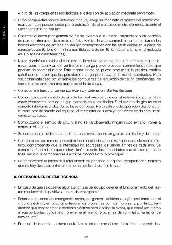
9.5.2. sUsTITUCIÓN DE fIlTrOs EN rECUPEraDOrEs EN lÍNEa
Paraextraerelfiltrosedebeabrirelregistrodeinspeccióncorrespondiente,desatornillandolostornillosquelosujetan.Seliberarálapalancatirandodeellahaciaabajoeinmediatamen-teelfiltrocaeráporsupeso.Retirarelfiltrodeslizándolohaciaelexterior.Reponerelfiltroyrepetirlaoperaciónalainversa.
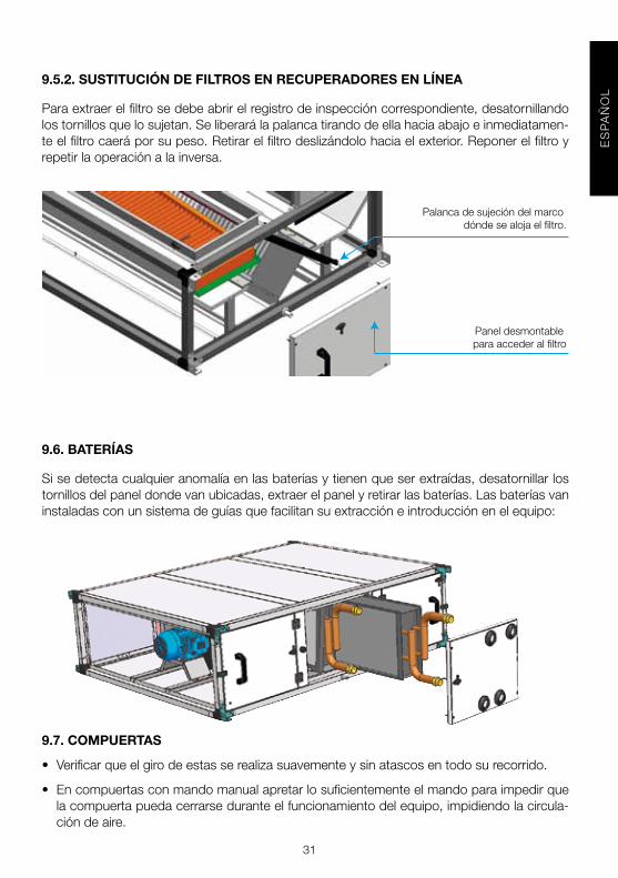
9.6. BaTErÍas
Sisedetectacualquieranomalíaenlasbateríasytienenqueserextraídas,desatornillarlostornillosdelpaneldondevanubicadas,extraerelpanelyretirarlasbaterías.Lasbateríasvaninstaladasconunsistemadeguíasquefacilitansuextraccióneintroducciónenelequipo:
9.7. COMPUErTas
• Verificarqueelgirodeestasserealizasuavementeysinatascosentodosurecorrido.
• Encompuertasconmandomanualapretarlosuficientementeelmandoparaimpedirquelacompuertapuedacerrarseduranteelfuncionamientodelequipo,impidiendolacircula-cióndeaire.

32
ES
PA
ÑO
L
9.8. sIlENCIaDOrEs
• Paraextraerelconjuntodelosbaflessedebedesmontarelpanellateralcorrespondiente,desatornillandolostornillosquelosujetan.
9.8.1. MÓDUlO DE MEZClas
• Módulode2vías:Seenvíasiempreconunaposiciónfijadelascompuertas,sinocoincideconlasnecesidadesdelainstalación,cambiarelpanelfrontaltalycomoseindica.
• Módulode3vías(A+B)(Mezcla):Cuandovaintercaladoentredosmódulossetienenquequitarlospanelesfrontalestalycomoseindica.(B)
a
B
quitarpanel
quitarpanel

33
ES
PA
ÑO
L
9.8.2. CaJa DE MEZCla 2 VÍas CON BaNCaDa Y TEJaDIllO
• Siempresesuministraráaizquierdasyencasodequeseaaderechas,elclientetendráquecambiardeposiciónelpanelfrontalconlacompuertasegúnimagen.
9.9. HUMECTaDOr
• El humidificador evaporativo es una sección concebidapara aumentar el contenidodevapordeaguadelairetratadoporevaporaciónnaturaldelaguaenfaselíquida.Elcaudaldeaireahumidificaratraviesaunpaneldecelulosaonduladoconimpregnacionesquímicasqueledanrigidez,esponjosidadypropiedadesanti-incrustantes,queestácontinuamentemojadoporunsistemaderecirculacióndeagua(nosuministrado).
• Comprobarquelabandejaderecogidadeaguamantieneelniveladecuado.
• Comprobarlabuenadistribucióndeaguaportodoslospanelesdelhumectador.
• Lospanelesdecelulosanopuedensoportartemperaturasdeairesuperioresa60ºC,tem-peraturaapartirdelacualempiezaatostarseyexistenriesgosdecombustión.Asegurarsedequeestonopuedasucederyensucasopreverunsistemadealarmasiseproduceestehecho.
• Secomprobaráqueelriegodelospanelestengaunexcesodeaguaquecaealabandejasinquereboseporlaschapasdecerramientodelsistemaderiego.
• Sedeberáajustarelcaudaldeaguadelabombaobservandoperiódicamenteelestadodelospaneles(ensucaradeentradadeaire).Sepuedereducirsinoaparecendepósitosmineralesblanquecinosensusuperficieo,porelcontrario,aumentarlosiseobservande-pósitosdecal.
• Suvidaoperativa(contandoconsuministrodeaguapotablenormalconvaloresdepHentornoa7)dependefundamentalmentedelcorrectofuncionamientodelsistemadepurgacontinuaydesconcentracióndesalesminerales.Sinoseoperaadecuadamente,lospa-neleshabráquesustituirlesenbreveplazoporbloquearseloscanalesdepasodeaireporlosdepósitoscalizos.
• Larecuperacióndelospanelespuedeintentarsemediantesuinmersiónenunadisolucióndeácidoacéticodébil(15-20%)oenvinagredevino.
• Asimismoenlosperiodoslargosdeinactividadesimprescindiblevaciarylimpiartotalmen-telabandeja.

34
ES
PA
ÑO
L
9.10. rECUPEraDOr
Paraextraerelrecuperadorsedebeabrirelregistrodeinspeccióncorrespondiente,desator-nillandolostornillosquelosujetan.Deslizarelintercambiadorparaprocederasuextracción.
¡¡¡ATENCIÓN!!!Sostenerconunamanoelinter-cambiadorduranteestaoperaciónparaevitarsucaídaporgravedad(riesgodedañosenelintercambiador y riesgo de accidente para eltécnicoquerealizalaoperación).Paraextraerelintercambiadordesuubicación,deslíceloporsusguías,tirandodelosángulosynodelasaletasdel intercambiador,paranodañarlo. Limpie el intercambiador con aire comprimi-dooconunaspiradorylávelocondetergentenoagresivo.Elmantenimientoperiódicoreco-mendadoesdeunavezporcadaestaciónenfuncionamiento.
10. rECIClaJE
LanormativadelaCEEyelcompromisoquedebemosadquirirconlasfuturasgeneraciones,nosobliganalrecicladodemateriales;lerogamosquenoolvidedepositartodosloselemen-tossobrantesdelembalajeenloscorrespondientescontenedoresdereciclaje,asícomodellevarlosaparatossustituidosalGestordeResiduosmáspróximos.

35
EN
GL
ISH
ENGLISH
TaBlE Of CONTENTs
1. OVERVIEW . . . . . . . . . . . . . . . . . . . . . . . . . . . . . . . . . . . . . . . . . . . . . . . . . . . . . . . . . . . . . . . . 362. SAFETY STANDARDS AND “EC” MARKING . . . . . . . . . . . . . . . . . . . . . . . . . . . . . . . . . . . . . . . . . . . . . . . . 363. GENERAL STANDARDS . . . . . . . . . . . . . . . . . . . . . . . . . . . . . . . . . . . . . . . . . . . . . . . . . . . . . . . . . . . . . . . . 364. UNIT LABELING . . . . . . . . . . . . . . . . . . . . . . . . . . . . . . . . . . . . . . . . . . . . . . . . . . . . . . . . . . . . . . . . 375. HANDLING . . . . . . . . . . . . . . . . . . . . . . . . . . . . . . . . . . . . . . . . . . . . . . . . . . . . . . . . . . . . . . . . 376. INSTALLATION . . . . . . . . . . . . . . . . . . . . . . . . . . . . . . . . . . . . . . . . . . . . . . . . . . . . . . . . . . . . . . . . 38 6.1. OVERVIEW . . . . . . . . . . . . . . . . . . . . . . . . . . . . . . . . . . . . . . . . . . . . . . . . . . . . . . . . . . . . . . . . 38 6.2.IDENTIFICATION OF PARTS OF THE UNIT . . . . . . . . . . . . . . . . . . . . . . . . . . . . . . . . . . . . . . . . 38 6.3. INSTALLATION SITE . . . . . . . . . . . . . . . . . . . . . . . . . . . . . . . . . . . . . . . . . . . . . . . . . . . . . . . . . . 39 6.4. MAINTENANCE SPACE . . . . . . . . . . . . . . . . . . . . . . . . . . . . . . . . . . . . . . . . . . . . . . . . . . . . . . . 39 6.5. ASSEMBLING THE MODULES . . . . . . . . . . . . . . . . . . . . . . . . . . . . . . . . . . . . . . . . . . . . . . . . . 41 6.5.1. COVER SEAMS . . . . . . . . . . . . . . . . . . . . . . . . . . . . . . . . . . . . . . . . . . . . . . . . . . . . . 41 6.5.2. ASSEMBLING FLEXIBLE CONNECTIONS . . . . . . . . . . . . . . . . . . . . . . . . . . . . . . . 41 6.5.3. ASSEMBLING UNITS SIDE BY SIDE . . . . . . . . . . . . . . . . . . . . . . . . . . . . . . . . . . . . 42 6.6. ELECTRICAL CONNECTION . . . . . . . . . . . . . . . . . . . . . . . . . . . . . . . . . . . . . . . . . . . . . . . . . . . 43 6.6.1. CONNECTING THE MOTORS . . . . . . . . . . . . . . . . . . . . . . . . . . . . . . . . . . . . . . . . . 44 6.6.2. CONNECTING THE ELECTRICAL HEATER . . . . . . . . . . . . . . . . . . . . . . . . . . . . . . 44 6.7. CONNECTING THE PRESSURE SENSORS . . . . . . . . . . . . . . . . . . . . . . . . . . . . . . . . . . . . . . . 49 6.7.1. DIRTY FILTERS . . . . . . . . . . . . . . . . . . . . . . . . . . . . . . . . . . . . . . . . . . . . . . . . . . . . . . 49 6.7.2. FAN CONTROLS . . . . . . . . . . . . . . . . . . . . . . . . . . . . . . . . . . . . . . . . . . . . . . . . . . . . . 49 6.7.2.1. CONNECTING THE CONSTANT PRESSURE OR CONSTANT AIRFLOW EQUIPMENT . . . . . . . . . . . . . . . . . . . . . . . . . . . . . . . . . . . 49 6.7.2.2. CONFIGURING THE DIFFERENTIAL PRESSURE TRANSMITTER (TDP-S & TDP-D) . . . . . . . . . . . . . . . . . . . . . . . . . . . . . . . . . . . . . . . . . . . . . . . . . 50 6.7.2.2.1. TDP-S MODEL . . . . . . . . . . . . . . . . . . . . . . . . . . . . . . . . . . . . . . . . . . . . 51 6.7.2.2.2. TDP-D MODEL . . . . . . . . . . . . . . . . . . . . . . . . . . . . . . . . . . . . . . . . . . . . 52 6.7.2.2.3. CALIBRATION OF THE PRESSURE TRANSMITTER (TDP-S and TDP-D) . . . . . . . . . . . . . . . . . . . . . . . . . . . . . . . . . . . . . . . . 54 6.7.2.3. CONFIGURING THE VARIABLE FREQUENCY DRIVE . . . . . . . . . . . . . . . . . . . . . 54 6.7.2.3.1. SETTING THE WORKING POINT . . . . . . . . . . . . . . . . . . . . . . . . . . . . . . 54 6.7.2.3.2. OPERATION AND FAULTS . . . . . . . . . . . . . . . . . . . . . . . . . . . . . . . . . . . 55 6.7.2.3.3. RECONFIGURING THE FREQUENCY INVERTER . . . . . . . . . . . . . . . . . 56 6.8. CONNECTING THE UNIT TO THE WATER NETWORK . . . . . . . . . . . . . . . . . . . . . . . . . . . . . 58 6.9. CONNECTING THE UNIT TO THE DUCT SYSTEM . . . . . . . . . . . . . . . . . . . . . . . . . . . . . . . 59 6.10. DRAINAGE SYSTEM . . . . . . . . . . . . . . . . . . . . . . . . . . . . . . . . . . . . . . . . . . . . . . . . . . . . . . . . 59 6.11.INSTALLING DAMPERS BOXES . . . . . . . . . . . . . . . . . . . . . . . . . . . . . . . . . . . . . . . . . . . . . . . . 607. START-UP PROCEDURE . . . . . . . . . . . . . . . . . . . . . . . . . . . . . . . . . . . . . . . . . . . . . . . . . . . . . . . . . . . . . . . 608. EMERGENCY OPERATIONS . . . . . . . . . . . . . . . . . . . . . . . . . . . . . . . . . . . . . . . . . . . . . . . . . . . . . . . . . . . . 619. PREVENTIVE MAINTENANCE . . . . . . . . . . . . . . . . . . . . . . . . . . . . . . . . . . . . . . . . . . . . . . . . . . . . . . . . . . . 61 9.1. HEAT EXCHANGER COILS . . . . . . . . . . . . . . . . . . . . . . . . . . . . . . . . . . . . . . . . . . . . . . . . . . . . 62 9.1.1. DX COILS . . . . . . . . . . . . . . . . . . . . . . . . . . . . . . . . . . . . . . . . . . . . . . . . . . . . . . . . . . 62 9.2.DRAINAGE SYSTEM . . . . . . . . . . . . . . . . . . . . . . . . . . . . . . . . . . . . . . . . . . . . . . . . . . . . . . . . . . 62 9.3. MOTORS . . . . . . . . . . . . . . . . . . . . . . . . . . . . . . . . . . . . . . . . . . . . . . . . . . . . . . . . . . . . . . . . 62 9.4. VENTILADORES . . . . . . . . . . . . . . . . . . . . . . . . . . . . . . . . . . . . . . . . . . . . . . . . . . . . . . . . . . . . . . 63 9.5. FILTERS . . . . . . . . . . . . . . . . . . . . . . . . . . . . . . . . . . . . . . . . . . . . . . . . . . . . . . . . . . . . . . . . 63 9.5.1. REPLACING THE FILTER IN THE MAIN UNIT AND SIDE-BY-SIDE OR STACKED RECOVERY UNIT. . . . . . . . . . . . . . . . . . . . . . 63 9.5.2. REPLACING FILTERS FOR IN-LINE RECOVERY MODULES . . . . . . . . . . . . . . . . . 64 9.6. COILS . . . . . . . . . . . . . . . . . . . . . . . . . . . . . . . . . . . . . . . . . . . . . . . . . . . . . . . . . . . . . . . . 64 9.7. DAMPERS . . . . . . . . . . . . . . . . . . . . . . . . . . . . . . . . . . . . . . . . . . . . . . . . . . . . . . . . . . . . . . . 64 9.8. SILENCER . . . . . . . . . . . . . . . . . . . . . . . . . . . . . . . . . . . . . . . . . . . . . . . . . . . . . . . . . . . . . . . . 65 9.8.1. MIXING MODULE . . . . . . . . . . . . . . . . . . . . . . . . . . . . . . . . . . . . . . . . . . . . . . . . . . . 65 9.8.2. MIXING BOX 2 WAY WITH BASE AND ROOF . . . . . . . . . . . . . . . . . . . . . . . . . . . . 66 9.9. RECOVERY UNIT . . . . . . . . . . . . . . . . . . . . . . . . . . . . . . . . . . . . . . . . . . . . . . . . . . . . . 6610. RECYCLING . . . . . . . . . . . . . . . . . . . . . . . . . . . . . . . . . . . . . . . . . . . . . . . . . . . . . . . . . . . . . . . . 67

36
EN
GL
ISH
1. OVErVIEW
• Weappreciatethetrustyouhaveplacedinusbypurchasingthisdevice.Youhavepurcha-sedahigh-qualityproductthathasbeenmanufacturedinstrictcompliancewithrecogni-zedtechnicalregulationsregardingsafety,andinaccordancewithECstandards.
• Readthisinstructionbookletcarefully,sinceitcontainsimportantinformationforyoursafetyduringtheinstallation,useandmaintenanceofthisproduct.
• Keepthisbookletincaseyouneedtoconsultitinthefuture.
• Weaskthatyoumakesuretheequipmentisinperfectconditionwhenyouunpackit,sinceanyexistingdefectiscoveredbytheS&Pwarranty.
• Techniciansresponsibleforinstalling,start-upandmaintenancemustreadtheinstructionsandbefamiliarwiththembeforestartingwork.
2. safETY sTaNDarDs aND “EC” MarKING
• S&Pengineersarefirmlycommittedtoresearchanddevelopmenttoachieveproductswithimprovedefficiencythatcomplieswithcurrentsafetystandards.
• Thestandardsandrecommendationsindicatedbelowreflectcurrentstandardsinthefieldof safety, and therefore are based primarily on meeting standards of a general nature.Consequently,werecommendthatallpersonnelexposedtorisksadherestrictlytolocalregulationsinforceregardinghazardprevention.
• S&Pisinnowayresponsibleforanydamageorinjurycausedtopersonsorobjectsresul-tingfromfailuretocomplywithsafetystandards,andanypossiblemodificationstothepro-duct.TheECsealandstatementofconformityserveasproofoftheproduct’scompliancewithapplicableEuropeanCommunitystandards.
3. GENEral sTaNDarDs
• ProductriskshavebeenanalysedpursuanttotheprovisionsoftheMachineryDirective.Thismanualcontainsinformationintendedforallpersonnelexposedtohazards,withthegoal of preventingpersonal injuriesordamage toobjects resulting frommishandlingorimpropermaintenance.Allmaintenanceservicework(correctiveandpreventive)mustbeperformedwiththeequipmentstoppedanddisconnected.
• Toavoiddangerofpossibleaccidentalstartupensurethattheequipmentiselectricallyiso-latedandlocked.Ifthisisnotpossible,warningsignsshouldbeplacedonmaindistributionconsolethatstate:
“WarNING: controls disconnected for maintenance”
• Beforeconnectingthepowercabletothemotors,makesurethatthevoltageonthelinematchesthevoltageindicatedontheunit’sidentificationplate.

37
EN
GL
ISH
4. UNIT laBElING
• Theunitcomeswithavarietyoflabelsthatmustnotberemoved.Herewithsamplelabelsandmeaning:
ICON / laBEl MEaNING
Signingonfanaccessdoor. Indicatesthat the equipment must be discon-nected, followedby awaitingperiod,since there are moving parts thatconstitutedangertoentry.
Indicatesdirectionofairflowintheunit.
Indicates the inlet/outlet for the coldwaterheatexchanger.
Indicates the inlet/outlet for the hotwaterheatexchanger.
Unitidentificationplate.Thisindicates:-Model-Code-Serialnumber-Dateofmanufacture-Outputpowerofinstalledmotors(Kw)-Maximumabsorbedcurrentofmotor(A)-Powerofinstalledelectricheater-Electricalsupply
5. HaNDlING
• Whenunitreceived,unpackandmakesurethepackagingisintact;anydefectmayindicatedamagetotheequipment.Reviewitcarefullytomakesurethatnopartsaremissing.
• Ifthereisanydamagetotheunitortheshipmentisnotcomplete,writedowntheproblemsonthedeliveryslipandsendaclaimtothecarrier.AlsoreportanyproblemstoS&P.
• Theclimatecontrolunitissuppliedinseparatemodules.Eachmodulemaybemovedtoitsfinalpointofinstallationonlyinthepositionwhichwillbeinstalled,exceptwhenexpresslyauthorisedbythemanufacturer.
• Componentsshouldbetransportedusingappropriatehoistandslings.Theequipmenthascornerlugsforloadingandunloading.

38
EN
GL
ISH
6. INsTallaTION
6.1. OVErVIEW
• Thetechnicianresponsibleforequipmentreceiptmustensurethatthecharacteristicsoftheexistingpowersupplyagreewiththeelectricaldataontheunit’sidentificationplate.
• Beforeinstallingtheequipmentinitsfinalposition,makesurethattheplacewhereitwillbelocatedisstrongenoughtosupportitsweight.
• Undernocircumstancesshouldtheseunitsbeinstalledinflammableorexplosiveenviron-ments,inenvironmentsthatcontainoilvapours,saltair,orcorrosiveenvironments.
• Equipmentinstallationcanpresenthazardsduetothematerialused,pressuresinthesys-temandtheelectricalcomponents.Forthisreason,onlytrainedandqualifiedserviceper-sonnelmayinstallserviceorrepairtheequipment.
• Asaprecaution,whenperformingoperationsinsidetheequipment,shutoffthepoweratamainbreaker.Thisservestopreventanyaccidentsinvolvingtheequipment’smovingparts,whichcanstartaccidentally,wellastopreventanydirectorindirectcontactwithliveparts.
• When installing theunit, itmustbe levelled toallow foragoodfitbetween thedifferentmodules,perfectcondensatedrainageandproperopeningofthedoors.
• Totestwhetherthefan is inperfectcondition,checkthecenteringof the intakeringbyturningtheimpellerbyhand.
6.2. IDENTIfICaTION Of ParTs Of THE UNIT
Themainmodulemayconsistofthreedifferentsections:filter,coilsandfans.However,oneofthefirsttwosectionsmaynotbeincluded.Thefollowingillustrationidentifiesthemaincom-ponentsofthemainmodule.

39
EN
GL
ISH
6.3. INsTallaTION sITE
• Avoidinstallingtheunitinareasnearheatsourcesorindampareaswheretheunitmightcomeincontactwithwater.
• Itisrecommendedthattheunitbeinstalledinaplacethatiseasilyaccessiblefortheinsta-llation.Providesufficientroomformaintenance,connectionanddrainageofcondensate.
6.4. MaINTENaNCE sPaCE
• Theinstallershouldleavesufficientunobstructedspacetoallowfreeaccesstotheunitformaintenance.Theamountofspaceneededwilldependonwhichsideoftheunitisperfor-mingtheextraction.Theunitisequippedwithsomesideaccessdoorsforaccesstothefiltersandfans.Toremovethecoils,thesidepanelmustberemoved.Boththefiltersandthefanscanberemovedfromeithersideoftheunit.
Model A (mm) B (mm)
UTBS-2 750 360
UTBS-3 1100 410
UTBS-5 1500 410
UTBS-8 1900 500

40
EN
GL
ISH
• Forceilingandfloor-mountedapplications,theunitmustbesuspendedfromthefourangle brackets oneachmodule,asfollows:
CEILINGMOUNTEDFLOORMOUNTED
WarNING! Due to the length and weight of the units, each module must be suspended separately.
Thereshouldbenothingblockingorrestrictingtheintakeofair.
MOUNTINGPOSITION

41
EN
GL
ISH
6.5. assEMBlING THE MODUlEs
Themoduleframeshavemountingbracketsoneachcornerthatareusedtosecuretheequi-pmenttotheceilingandtojointhevariousmodulestooneanother.Iftheunitismadeupofdifferentmodules,itwillbesuppliedwithajoiningkitwith4setsofbolts,washers,nutsandasealinggasket.
6.5.1. COVEr sEaMs
Ifyouhaveorderedaclimatecontrolunitforoutdoorusage,theequipmentwillcomeequip-pedwitharain-proofcover.Iftheclimatecontrolunitismadeupofoneormoremodules,theseamsbetweenthecoversmustbesealedasshownintheillustration:
6.5.2. assEMBlING flEXIBlE CONNECTIONs
• Ifyouhaveorderedflexibleconnectionsfortheendsoftheunits,theywillbesuppliedse-parately.

42
EN
GL
ISH
6.5.3. assEMBlING UNITs sIDE BY sIDE
Ifyouhaveorderedequipmentforside-by-sideinstallationofaheatrecoverymoduleorfreecoolingmodule,theequipmentwillbesuppliedwithjoiningbracketstojointhemodulesto-gether.Toattachthesebrackets,theequipmentmustbeaccessedfromtheinside:
- Place thebracket over the aluminiumstrip and tightenwith the two self-drillingscrews(1))
- Insertpackingstrip(2)- JointhemodulestogetherbysecuringthetwobracketsusinganM8bolt,washers
andanut(3))
Example of joining modules side by side:

43
EN
GL
ISH
6.6. ElECTrICal CONNECTION
• Beforeputtingtheunitinplace,makesurethatthenominalsupplyvoltagematchesthatlistedontheunit’sidentificationplate.
• It should be installed with cables whose cross-section meets current regulationsandpreventsoverheatingandvoltagedropsthatexceedpermissiblelimits.Currentregulationsmustbeobeyed,andthedesigner’sinstructionsmustbefollowedatalltimes.
• Beforeconnectingthecables,makesurethattheelectricity isturnedoffandthatthereisnovoltagepresentinanyofthem.
• Theinstallermustkeepthefollowingpointsinmindwhenperformingtheelectricalconnections:
-Anexternalcontrolmustbeinstalledthatoperatestheequipment.-Anemergencyshut-offswitchmustbeinstalledinthemostaccessibleplace
inordertostoptheequipmentintheeventofaproblem.-Themotorsmustbeconnectedfollowingtheinstructionsinthewiringsche-
matics for the terminal boxes for the various motors. The equipment hasglandsonthesideswherethepowerisconnectedforrunningpowercablestothemotors.
-Apoweroutlet,fuseor“U”curvethermo-magneticbreakermustbeinstalledforeachfan,whichwillprotecteachpowerlineintheevenofashortcircuit.
-The general power line must have a fuse or “U” curve thermo-magneticbreakerthatwillprotectthemainspowerintheeventofashortcircuit.
- Interlocked contactors with a thermal relay are recommended for use toprotectagainstover-current.
• The instructions in current regulations regarding the protection of electrical linesagainstdefectsanddirectandindirectcontactmustbeobeyedatalltimes.
• Afterthesestepsareperformed,checktomakesureallelectricalconnectionsaresecure(loosewiringconnectionscancauseirreparabledamage).
• Checktomakesuretheelectricalresistancebetweenearthandanyelectricaltermi-nalisgreaterthan1megohms.Ifitisnot,donotstartuptheunituntiltheelectricalshorthasbeenlocatedandrepaired.
• Asasafetymeasure,ifthereisnopowertothefan,thenecessaryinterlocksmustbeperformedsothatallotherelectricalcomponentsarealsode-energised.

44
EN
GL
ISH
6.6.1. CONNECTING THE MOTOrs
• Toconnectthemotors:- OntheUTBS-2andUTBS-3units,themotorterminalboxfacesthesidewiththe
inspectiondoortomakeiteasiertoaccess.
• Runthesleevethroughthecableglandinstalledontheunit:
6.6.2. CONNECTING THE ElECTrICal HEaTEr
• Usetheelectricheatertoheatcleanair.Fireriskisincreasedwhentheelectricheatergetsdirty,thereforeitisrecommendedtoplaceanairfilterbeforetheheatingelement.
• Theelectricalinstallermustprovideairflowcontroldevice,sothat,theelectricalheaterope-rateswhentheminimumairflowisreached,orwhentheairspeedovertheheaterismorethan1.5m/s.
• Theelectricheatershouldoperateifthefanisoff.Theelectricalheatershouldoperateafter,oratthesametimeasthefanisactivated.
• Thefanmuststayoffafterthestopandcoolingofthecoil.
• Donottouchtheheaterwhenitisworking.
• Incasethatoneofthecontroldeviceswasactivated,switchofftheunitandverifytheins-tallationbeforerestarting.

45
EN
GL
ISH
Conexionado electrico BE-2 15 kw 1 etapa catalogo
Conexionado electrico BE-2 7,5 kw 2 etapas catalogo
Theattachedschematicshowshowtoconnecttheresistorstotheelectricalheater:
WiringdiagramBE-215kW1step
WiringdiagramBE-27,5kW2steps
STANDARD:
A: HEATER ELEMENT 2,5 kWB: THERMAL PROTECTION R/AC: THERMAL PROTECTION R/M
STANDARD:
A: HEATER ELEMENT 2,5 kWB: THERMAL PROTECTION R/AC: THERMAL PROTECTION R/M
Sample of connection with regulator:
D: CONTROL TTC-2000E: SWITCHF: CONTACTORG: LINE PROTECTIONH: DUCT SENSOR TEMPERATURE(ACCESSORIES)
Sample of connection with regulator:
D: REGULATOR TTC-2000E: SWITCHF: CONTACTORG: LINE PROTECTIONH: DUCT SENSOR TEMPERATURE(ACCESSORIES)

46
EN
GL
ISH
Conexionado electrico BE-3 24 kw 1 etapa catalogo
Conexionado electrico BE-3 24 kw 2 etapas catalogo
WiringdiagramBE-324kW1step
WiringdiagramBE-324kW2steps
STANDARD:
A: HEATER ELEMENT 4,0 kWB: THERMAL PROTECTION R/AC: THERMAL PROTECTION R/M
STANDARD:
A: HEATER ELEMENT 4,0 kWB: THERMAL PROTECTION R/AC: THERMAL PROTECTION R/M
Sample of connection with regulator:
D: REGULATOR TTC-40 FE: SWITCHF: CONTACTORG: LINE PROTECTIONH: DUCT SENSOR TEMPERATURE(ACCESSORIES)
Sample of connection with regulator:
D: REGULATOR TTC-40 FE: SWITCHF: CONTACTORG: LINE PROTECTIONH: DUCT SENSOR TEMPERATURE(ACCESSORIES)

47
EN
GL
ISH
Conexionado electrico BE-5 18 kw 2 etapas catalogo
Conexionado electrico BE-5 12 kw 3 etapas catalogo
WiringdiagramBE-518kW2steps
WiringdiagramBE-512kW3steps
STANDARD:
A: HEATER ELEMENT 6,0 kWB: THERMAL PROTECTION R/AC: THERMAL PROTECTION R/M
STANDARD:
A: HEATER ELEMENT 4,0 kWB: THERMAL PROTECTION R/AC: THERMAL PROTECTION R/M
Sample of connection with regulator:
D: REGULATOR TTC-40 FD1: REGULATOR TT-S4E: SWITCHF:CONTACTORG: LINE PROTECTIONH: DUCT SENSOR TEMPERATURE(ACCESSORIES)
Sample of connection with regulator:
D: REGULATOR TTC-40 FD1: REGULATOR TT-S4E: SWITCHF:CONTACTORG: LINE PROTECTIONH: DUCT SENSOR TEMPERATURE(ACCESSORIES)

48
EN
GL
ISH
Conexionado electrico BE-5 18 kw 2 etapas catalogo
Conexionado electrico BE-5 12 kw 3 etapas catalogo
WiringdiagramBE-822,5kW2steps
WiringdiagramBE-815kW3steps
STANDARD:
A: HEATER ELEMENT 6,0 kWB: THERMAL PROTECTION R/AC: THERMAL PROTECTION R/M
STANDARD:
A: HEATER ELEMENT 4,0 kWB: THERMAL PROTECTION R/AC: THERMAL PROTECTION R/M
Sample of connection with regulator:
D: REGULATOR TTC-40 FD1: REGULATOR TT-S4E: SWITCHF:CONTACTORG: LINE PROTECTIONH: DUCT SENSOR TEMPERATURE(ACCESSORIES)
Sample of connection with regulator:
D: REGULATOR TTC-40 FD1: REGULATOR TT-S4E: SWITCHF:CONTACTORG: LINE PROTECTIONH: DUCT SENSOR TEMPERATURE(ACCESSORIES)

49
EN
GL
ISH
6.7. CONNECTING THE PrEssUrE sENsOrs
6.7.1. DIrTY fIlTErs
Theequipmentisequippedwith2pressuretapsoneachsideofthefilterssothatapressureswitchcanbeinstalledtocontroldirtlevelsinthefilters.Section9.5presentsatablewiththevaluesrecommendedforfilterreplacement.
6.7.2. faN CONTrOls
•Theunithas3pressuretapstomaintainthefanataconstantairfloworconstantpressure.Tobeabletocontrolthefansatconstantairflow,factorKshowninthefollowingtablemustbeentered:
UTBS-2 K=69
UTBS-3 K=84
UTBS-5 K=84
UTBS-8 K=104
6.7.2.1 CONNECTING THE CONsTaNT PrEssUrE Or CONsTaNT aIrflOW EQUIPMENT

50
EN
GL
ISH
• Checkthattheswitch“SW1”issettoSOURCE.
WARNING: in cases where a single variable frequency drive is used to control two motors, the thermal protection devices must be connected in series.
6.7.2.2 CONfIGUrING THE DIffErENTIal PrEssUrE TraNsMITTEr (TDP-s & TDP-D))
• Ifyouwishtoconfiguretheequipmenttooperateunderconstantpressurecontrol,youcanusedifferentialpressuretransmittermodelsTDP-SorTDP-D.IfyouwishtooperatewithconstantairflowcontrolyoumustusetheTDP-Dmodel.
The way you connect the pressure tubes depends on the type of control required, asshowninthediagrambelow:

51
EN
GL
ISH
Important:theupperpressuretubemustbeconnectedtothe“+”terminalandtheloweronetothe“-“terminal.Failingthis,thepressuremeasuredwillbeoutofrangeandthetransmitterscreenwillflash.
6.7.2.2.1 TDP-s MODEl
Air direction
CONsTaNT PrEssUrE CONTrOlLeaveoneofthepressuretapsunconnected.
CONsTaNT aIrflOW CONTrOlConnectthetwotapsandenterthevalueKshowninthetableaboveintothepressuretransducer.

52
EN
GL
ISH
CONsTaNT PrEssUrE OPEraTION
• Checkthatthetransmitteroutputsignaltypejumper(mA/V)inthevoltageposition(factorysetting).
• ConfiguretheDIPswitchesasindicatedinthetablesbelow.TherequiredpressurerangeisselectedusingtheswitchesDIP1,DIP2andDIP3.
Pressure range (Pa) DIP 1 DIP 2 DIP 3
-50...+50 1 1 1
0...+100 0 1 1
0...+150 1 0 1
0...+300 0 0 1
0...+500 1 1 0
0...+1000 0 1 0
0...+1600 1 0 0
0...+2500 0 0 0
DIP switch DIP 4/5/6 ON / OFF Notes
DIP 4 - Not used
DIP 5 Select according to the required damping time: 0,4s (OFF) / 10s (ON))
DIP 6 OFF Minimum output voltage 0V
6.7.2.2.2 TDP-D MODEl

53
EN
GL
ISH
CONsTaNT PrEssUrE OPEraTION
• Checkthatthetransmitteroutputsignaltypejumper(mA/V)inthevoltageposition(factory-setting).
•ConfiguretheDIPswitchesasindicatedinthetablebelow:
DIP switch ON / OFF Notes
DIP 1 - Not used
DIP 2 - Not used
DIP 3 - Not used
DIP 4 OFF Pressure mode (Pa)
DIP 5 Select according to the required damping time: 0,4s (OFF) / 10s (ON)
DIP 6 OFF Minimum output voltage 0V
• Set the pressure range: Press the “OK” button and move to the required range usingbuttons“”and“”.Finallypress“OK”againtosavetheconfiguration.Thepressurerangeswhichmaybeselectedareasfollow:-50...+50Pa;0...+100Pa;0...+150Pa;0...+300Pa;0...+500Pa;0...+1000Pa;0...+1600Pa;0...+2500Pa.
CONsTaNT flOW OPEraTION
OnlyavailablewiththeTDP-Dmodel.Inthismodeofoperationthepressuretransmitterconvertsthepressuredifferential(∆P)toaflow(qv)basedonthefollowingequation:
qv=k √∆P
• Place the transmitter’s output signal type jumper (mA/V) in the voltageposition (factorysetting).
•ConfiguretheDIPswitchasindicatedinthetablebelow:
Microswitch DIP ON / OFF Notes
DIP 1 - Not used
DIP 2 - Not used
DIP 3 - Not used
DIP 4 ON Flow mode
DIP 5 Select according to the required damping time: 0,4s (OFF) / 10s (ON)
DIP 6 OFF Minimum output voltage 0V

54
EN
GL
ISH
•Settheflowrangeandtheparameterk:Pressthe“OK”buttontoaccesstheairflowrangeselection.Pressagaintoaccesstheindividualdigitsoftheparameterk,onebyone,withtheoptionofselectingornotselectingadigitafterthedecimalpoint.Usingbuttons“”y“”youcansettherequiredvalues.Finallypress“OK”tosavetheconfigurationandexitthesettingsmenu.Theflowrangeswhichmaybeselectedareasfollow:100m3/h;300m3/h;500m3/h;1000m3/h;3000m3/h;5000m3/h;9999m3/h;30m3/hx1000;50m3/hx1000;99,99m3/hx1000.Theunitsm3/hcanbechangedtol/s.
•Attachtheadhesivelabelcorrespondingtotheunitofmeasurementusedforparameterk(m3/h,l/s,m3/hx1000,l/sx1000).
6.7.2.2.3 CalIBraTION Of THE PrEssUrE TraNsMITTEr (TDP-s aND TDP-D)
Oncefullyconnectedwerecommendyoucarryoutazerocalibration:Afterturningontheequipment(thegreenLEDisilluminated)waitafewmomentsuntilthetransmitterreachesitsnormalworkingtemperature.Thenpressthezerosetbutton.TheyellowLEDflashesuntilthecalibrationprocessiscomplete.Foracorrectcalibration,thepressureinthe+and–terminalsmustbethesame.Itisrecommendedthatthetubesaredisconnected.
6.7.2.3 CONfIGUrING THE VarIaBlE frEQUENCY DrIVE
Thefrequencyinvertercomespre-configuredbySoler&Palautooperateunderconstantpres-sureorconstantairflowandtheonlysettingrequiredistoconfigurethedesiredworkingpointfrequency.
6.7.2.3.1 sETTING THE WOrKING POINT
Theoperating frequency range ispresetbydefaultbetween20Hzand50Hz. Insomecir-cumstances, theworkingpointneedsanoutput frequencyhigher than50Hz, so that it isnecessarytoreconfigurethisparameter.resetting this parameter is only required if the working point frequency is above 50Hz,otherwiseitisnotnecessary.This data item can be found in the equipment selections sheetandcorrespondstothesystem’smaximum operating point. Tomaketheadjustment,proceedasdescribedbelow:
Tomovebetweenthevariousmenus,andbetweenvaluesofaparameterwithinamenu,turnthewheel.Toaccessaparticularmenuandtoselectthevalueofaparameter,press“ENT”.Toreturntothepreviousmenuortoexittheselectionofaparameterpress“ESC”.

55
EN
GL
ISH
Firstly, enter programming mode. The inverter has two operating modes, RUN and PRO-GRAMMING.Tomovefromonetotheother,pressESCfortwoseconds.
• PressESCfortwosecondsuntilthemodeindicatorLEDsflashsimultaneously.
Nextunlocktheinverter:• Press“ENT”andturnthewheeluntilyoureachthe“SUP-“menu• Press“ENT”andturnthewheeluntilyoureachthe“COD”parameter• Press“ENT”andturnthewheeluntil“1951”appears• Press“ENT”andturnthewheeluntil“OFF”appears• Press“ENT”andreturntothemainmenubypressing“ESC”twice
Checkifthevalueofthe“tFr”parameteronthe“drC”menuisgreaterthanorequaltothevalueoftheequipment’sworkingpointfrequency.Ifitisnot,changetheparametertoavaluegreaterthanorequaltotheequipment’sworkingpoint:• Press“ENT”andturnthewheeluntilyoureachthe“drC-“menu• Press“ENT”andturnthewheeluntilyoureachthe“tFr”parameter• Press“ENT”andturnthewheeluntilthevalueisgreaterthanorequaltotheequipment’s
workingpointfrequency• Press“ENT”andreturntothemainmenubypressing“ESC”twice
Then,enterthevalueoftheequipmentworkingpointfrequencyinthe“HSP”parameterofthe“Set”menu::• Turnthewheeluntilyoureachthe“Set-“menu• Press“ENT”andturnthewheeluntilyoureachthe“HSP”parameter• Press“ENT”andturnthewheeluntilthe value of the equipment working frequency
has been entered• Press“ENT”andexittheconfigurationmenubypressing“ESC”threetimes
Finally,againpress“ESC”fortwosecondsuntilthe3indicatorLEDslightsequentiallytoreturntoRUNmode(automaticfrequencyconverteroperationmode).
6.7.2.3.2 OPEraTION aND faUlTs
starting up the equipment:Theequipmentstartsupautomaticallywhenthepowersupplyisconnected.ThevalueofthesetpointcanbechangedusingtherPIparameter,whichcanbeaccessedfromthe“rEF”,“Set”menusandthe“-PI”submenuofthe“Fun”menu.
Locationofthe3ModeLeds.Dependingonhowtheyarelitup,theyindicatetheselectedmode:
-SEQUENTIALLY:Runmode-SIMULTANEOUSLY:Programmingmode

56
EN
GL
ISH
steps to follow in the event of a fault on the frequency inverter:Toavoidpossibleinjurytopersonnel,theinverterhastoberesetmanually.Intheeventofafault,proceedasdescribedbelow:• Disconnecttheinverterfromthepowersupply• Solvetheproblem• Reconnectthepowersupply(theinverterwillstartupautomatically)
6.7.2.3.3 rECONfIGUrING THE frEQUENCY INVErTEr
Intheeventthatconfigurationsettingsarelostduetoafrequencyinverterfault,proceedasdescribedbelow.Firstly enter programming mode. The inverter has two operating modes, RUN and PRO-GRAMMING.Tomovefromonetotheother,pressESCfortwoseconds.
• PressESCfortwosecondsuntilthemodeindicatorLEDsflashsimultaneously.
Nextunlocktheinverter:• Press“ENT”andturnthewheeluntilyoureachthe“SUP-“menu• Press“ENT”andturnthewheeluntilyoureachthe“COd”parameter• Press“ENT”andturnthewheeluntil“1951”appears• Press“ENT”andturnthewheeluntil“OFF”appears• Press“ENT”andreturntothemainmenubypressing“ESC”twice
Resettofactoryconfiguration:• Gotothe“drC”menuandpress“ENT”• Moveto“CFG”andpress“ENT”• Select“Std”andpress“ENT”• Press“ESC”toexitandusethewheeltomoveto“FCS”• Press“ENT”andmoveto“In1”• Press“ENT”andtheinverterwillberesettothefactoryconfiguration
Proceed to reconfigure the frequency inverter. To do this, set the parameters in the tablebelow:
Menu Parameter Value
CtL LAC L3
CtL Fr1 AI1
CtL Fr2 AIU1
CtL rFC LI3
FLt Atr nO
FLt FLr YES
FLt EtF LI5
FLt LEt LO
drC tUn YES
drC UFt nLd

57
EN
GL
ISH
Menu Parameter Value
drC SFr 8 kHz
I-O tCC 2C
I-O tCt LEL
I-O rrS nO
Set LSP 20 Hz
FUn PSS PS2 nO
FUn PSS PS4 nO
FUn SAI SA2 nO
FUn PI PIF AI1
FUn PI rPG 0,2
FUn PI rIG 0,2
FUn PI PII YES
FUn PI rPI 50,0
FUn StC Stt nSt
FUn AdC AdC nO
Entertheratedvaluesfromthenameplateforthemotorusedintheparametersshowninthetablebelow:
WarNING: where using a single frequency inverter to control two motors, double the value of the rated current “nCr”
Menu Parameter Notes
drC bFr Rated frequency of the fan
drC UnS Rated voltage of the motor as shown on the name plate
drC FrS Rated frequency of the motor as shown on the name plate
drC nCr Rated current of the motor as it appears on the name plate
drC nSP Rated speed of the motor as shown on the name plate
drC COS Cosine of the phase offset angle of the motor as shown on the name plate
Finallyagainpress“ESC”fortwosecondsuntilthe3indicatorLEDslightsequentiallytoreturntoRUNmode(automaticfrequencyinverteroperationmode).
58
EN
GL
ISH
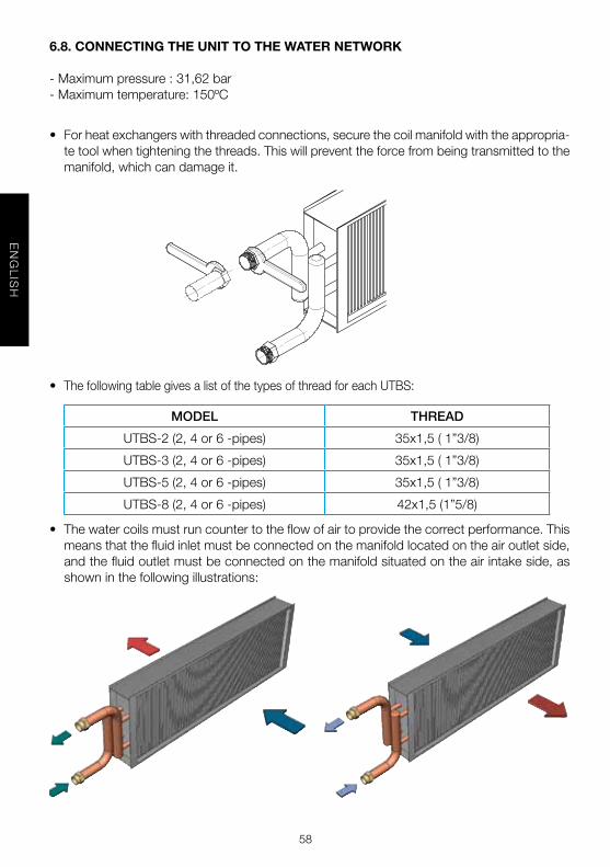
6.8. CONNECTING THE UNIT TO THE WaTEr NETWOrK
-Maximumpressure:31,62bar-Maximumtemperature:150ºC
• Forheatexchangerswiththreadedconnections,securethecoilmanifoldwiththeappropria-tetoolwhentighteningthethreads.Thiswillpreventtheforcefrombeingtransmittedtothemanifold,whichcandamageit.
• ThefollowingtablegivesalistofthetypesofthreadforeachUTBS:
MODEL THREAD
UTBS-2(2,4or6-pipes) 35x1,5(1”3/8)
UTBS-3(2,4or6-pipes) 35x1,5(1”3/8)
UTBS-5(2,4or6-pipes) 35x1,5(1”3/8)
UTBS-8(2,4or6-pipes) 42x1,5(1”5/8)
• Thewatercoilsmustruncountertotheflowofairtoprovidethecorrectperformance.Thismeansthatthefluidinletmustbeconnectedonthemanifoldlocatedontheairoutletside,andthefluidoutletmustbeconnectedonthemanifoldsituatedontheairintakeside,asshowninthefollowingillustrations:

59
EN
GL
ISH
• Wesuggesthavingall theelementsneeded for the installationonhand,mentioning thefollowingdevicesinparticular:
-Unitintakepre-filterthattrapssuspendedparticulatematter.-Bleedvalvesshouldbefittedateachofthehighpointsintheinstallationtomaintain
goodwatercirculation.- It is recommended tokeepwater in thehydraulicsystematall times (install an
auto-fillervalveandpressureswitchesthatsendanalarmandshutoffpowertotheequipment,etc.)
-Checktomakesurethattheflowofwatercirculatingthroughtheunitisappropriate.-Shut-offvalvesmustbeinstalledateachconnectiononthewaterlinetoallowthe
unittobeisolatedifnecessary(tocleanfilters,makerepairs,replacepartsetc.)andavoidtheneedtocompletelydrainthewatercircuit.
- Anti-vibrationbellowsshouldbe installedat the inletandoutlet from theunit topreventthetransmissionofvibrationsthatcouldresultindamagetotheheatex-changercoilsduetoexcessstressonthecircuits.
6.9. CONNECTING THE UNIT TO THE DUCT sYsTEM
• Neverusetheunitasasupportorweight-bearingstructureforductwork.
• Connecttheunittotheairductsusingflexibleconnectorstopreventvibrationsfrombeingtransmittedtotheductsystem.
• Checktomakesureairintakeandflowarenotbeingblockedandthattherearenoobsta-clesimpedinggoodaircirculation.Failuretodosowillaffecttheefficiencyofthesystem.
6.10. DraINaGE sYsTEM
• AsiphonmustbeinstalledwithpressureheaddifferenceinmmWGgreaterthanthepres-sureprovidedbythefan,tofacilitatedrainingcondensatefromthetray.
• Thedrainagesystemshouldhaveaminimumslopeof2%.

60
EN
GL
ISH
VErY IMPOrTaNT:
•Thepanelmanufacturingprocessimpregnatesthemwithchemicalagentsthathavea characteristic strongodour. Toprevent thisodour frombeing transmitted tooc-cupiedspaces, it isrecommendedthatthewaterrecirculationpumpbeallowedtoruncontinuouslyfor24hoursWITHOUTRUNNINGTHEFANtowashoffthepanels.Afterwards,draintherinsewaterbeforecommencingnormalstart-up.
6.11. INsTallING DaMPEr BOXEs
• Makesurethatthesecanberotatedwithgentlepressure,withnobindinganywhereintheirrangeofmotion.
• For manually controlled damper boxes, tighten the control sufficiently to prevent thedamperfromclosingwhiletheunitisrunning,blockingoffthecirculationofair.
• Ifthemixingboxiscontrolledbyaservomotor,connectitaccordingtothemanufacturer’sinstructions.However,thelevershouldberemovedbeforeinstallingtheservomotor.
7. sTarT-UP PrOCEDUrE
• Allaccesspanelsontheunitmustbeclosedbeforestarting.
• Makesurethattheearthconnectionissecurelyconnected.
• First turnon thewatercirculationpump.Waitseveralminutes tomakesure theflowofcirculationremainssteadyandthatthereisnovariationintheflow.Makesurethatanyairbubbleshavebeendrawntothebleedpointsandthattheyhavebeenbledoff.
• Makesurethatthepressuresintheunitdonotexceedthemaximumpressurefortheex-changercoils.
• Continuetorunthecirculationpumpforatleast2hours.Turnoffthepumpandthenre-movethefilterfromtheunit.Todoso,closetheappropriateshut-offvalvestopreventthewaterlinefromemptying,andtopreventairfromgettingin.Thencleanthefilter.
• Takeacarefullookattheparticlestrappedinthefilter.Makesurethattheseparticlesarenotcomingfromasourcethatwillclogthefilteragain(suchaspipescalefromironpipes,hardwaterdeposits,etc.).
• Re-insertthefilter,bleedtheairfromthesystemandturnthecirculationpumponagain.Waitseveralmoreminutestomakesurethattheflowofwaterremainssteadyandthereisnovariationintheflow.Ifgoodwatercirculationisnotachieved,repeatthestepsdescribedabove.
• Beforeturningonthepowertotheunit,checktomakesurethatnothingishinderingthemovementoftheregulatordampersiftheseareoperatedusingaservomotor.
• Ifthedamperaremanuallyoperated,makesurebymanuallytighteningthecontrolthattheycannotbeclosedduetotheforceofairoranythingelsewhiletheunitisrunning.

61
EN
GL
ISH
• Turnontheexternalmainpowerswitchtotheunit,keepingthecontrolswitchintheoffposition.Afterthat,checktomakesuretheinputvoltageattheunit’selectricalterminalsmatches theone indicatedon the identificationplate (theminimumvoltagewillbe10%belowtheratedvoltageindicatedontheidentificationplate).
• Donotstartupthefaniftheductnetworkisnotcompletelyclosed,sinceturningonthefanwithnoloadcancauseover-currentsthatcauseweartothemotor.Thiscanalsooccurifthestaticpressuredemandedisgreaterthanthepressurelossesthatoccurintheductnetwork.Tofixthis,closetheflowregulatordamperssothatthere isagreaterpressureloss.
• Turnontheexternalcontrolswitchandstopitafewsecondslater.
• Makesurethatthemotorsarerotatinginthedirectionsetbythemanufacturer(notethedirectionofrotationmarkedonthefan). Ifthedirectionofrotationis incorrect,swapthepowerphases.Todoso,disconnecttheunitcontrolswitchandthemainswitchandthenswapthephases.
• Onceyou’vecheckedthedirectionofrotation,ifyouhavenotnotedanystrangenoises,youmayturntheunitonagain.
• Testfanandmotorrotationspeedusingatachometer.
• Makesurethattheunitreceivesadequateairflow,orelseitsperformancewillbeseriouslycompromised.
• Withtheunitrunning,testthecurrentdrawnbyeachelectricalcomponent,checkingtomakesurethatthecurrentdoesnotexceedthelimitsforeachcomponent.Alsomakesuretherearenophaselagsbetweenthecurrentscirculatingoneachline,exceptwhensingle-phaseelectricalcomponentscausethis.
• Testthetotalcurrentdrawnbytheunitasawhole,alsocheckingtomakesuretherearenophaselagsbetweenthecurrentsonthedifferentlines.
8. EMErGENCY OPEraTIONs
• Ifanyproblemsarenotedontheunit,turnitoffusingtheemergencyshut-offdevice.
• Theseemergencyoperationswillgenerallybetheresultofsomeproblemwiththeelectricalcircuit,inwhichcaseyoumayhaveproblemswiththemotors.Youwillthereforeneedtodisconnectthepowertolocatethefault,whichmaybeinsidetheunit(shortcircuit)orex-ternaltoit(problemswiththepowersupply,voltagevariations,etc.).
• In the event of fire, it must be extinguished using suitable extinguishers. Extinguishersshouldbeappropriateforuseonelectricalfires.
9. PrEVENTIVE MaINTENaNCE
• Preventivemaintenanceisapresetprogrammeofchecksthatisfollowedregularlytopre-ventequipmentbreakdowns.

62
EN
GL
ISH
• ThesupplementalBuildingFacilityTechnicalRegulationsareapplicableatalltimestomain-tenancestandards,exceptwhenjustifiedotherwisefortechnicalreasons.
• Themaintenancesupervisorshouldkeepacopyof thepreventivemaintenance recom-mendationsgivenbelowonfile,makingasmanycopiesasneededforuse.
• Accordingtotheequipment’soperatingneeds,itiscrucialtomakealistofthoseelementsthatareneeded toquickly resolveequipment faults.This listwillserve todetermine thesparepartsinventoryneededtobeabletoperformrepairsquickly.
• Amaintenancelogshouldrecordeachcomponentservicedduringmaintenance,aswellasactivitiesperformedorrepairsmade.
• Maintenancestaffmusthaveaccesstoaspecifictrainingprogramme.
• Beforestartingmaintenanceoperationsontheunit,turnofftheunit’smainswitch.Electricalshockcancausepersonalinjury.
• Keepthefollowinginmindwhenperformingmaintenanceoperations:
9.1. WaTEr COIls
• Werecommendcleaningthecoilsonceayear.
• Don’tuseabrasivecleaner.
• Brushoffthefinsthatneedit.
• Makesurethatthereisnoleakagefrompipework.
• Ifthecoilsarenotused,pleasedrainthewatertoavoiddamage.
9.1.1 DX COIls
• Werecommendcleaningthecoilsonceayear.
• Don’tusetheabrasivecleaner.
• Makesurethatthereistheleakagefrompipework.
9.2. DraINaGE sYsTEM
• Werecommendcheckingperiodicallythecondensatedriptrayandcleanit.
• Werecommendcheckingthesiphon.
9.3. MOTOrs
• Checkthepowerconsumptionhasnotincreased.
• Periodically check the electrical connections aremakinggoodcontact; thiswill preventbreakdowns.
• Werecommendcheckingthefanmountingperiodically.

63
EN
GL
ISH
9.4. faNs
• Everythreemonths,cleanthedirtfromthefanbladesandbearings,sincedirtcannotonlyreduceairflowbutalsoleadtounbalancedoperationandincreasenoise.
• Periodically,testtheairflowoneachfan.
9.5. fIlTErs
• Tomakesurethatthefiltersareworkingproperly,thepressurelossacrossthefiltermustbemonitoredprecisely(sincethisisanindicatorofdirtlevels).Thefollowingtableindicatesthemaximumrecommendedvaluesforpressurelossbeforefilterreplacement.
Filter G4 F5 F6 F7 F8 F9
Pressure Loss (Pa)
150 200 200 200 225 225
• Evenifthemaximumpressurelosshasnotbeenreached,filtersshouldbeinspectedeachmonthtomakesurethatthefilterandfilterhousingaresealed.
• Itisnotrecommendedthatfiltersbewashed,sincetheywillneverrecovertheirinitialeffi-ciencyanddoingsocanproducewearonthefilters.Althoughwashingorvacuumingintheoppositedirectionfromnormalaircirculationcanachieveanoptimalfinish,itisrecom-mendedthatyoualwayshaveasetofreplacementfiltersonhand.Undernocircumstancesshouldtheunitberunwithoutfilters,sincethiscanintroducedirtintovitalcomponentsoftheunitandleadtoequipmentwearandlossofefficiency.
9.5.1. rEPlaCING THE fIlTEr IN THE MaIN UNIT aND sIDE-BY-sIDE Or sTaCKED rECOVErY UNIT.
Toremovethefilter,opentheinspectiondoor,andremovethefilterbypullingitout.Forthehighefficiencyfilters(fromF6),aneasyfixingsystemisusedtoassurehighertightness.Turnhandleandremovethefilter.Thissystemisfoundonthefiltermodulesandside-by-sideorstackedheatrecoverymodulestoo.

64
EN
GL
ISH
9.5.2. rEPlaCING fIlTErs fOr IN-lINE rECOVErY MODUlEs
Toremovethefilter,opentheinspectiondoorbypullingitout.Turnthehandleandremovethefilter.
9.6. COIls
Ifyoudetectanyprobleminthecoilsandtheyneedtoberemoved,loosentheboltsfromthepanelwheretheyarelocated,removethepanelandextractthecoils.Thecoilsareinstalledinslodforeasyslideinandslideout.
9.7. DaMPErs
• Makesurethatthedampercanopenandcloseunrestrictedlyandthe(way)isunobstruc-ted.
• Formanuallycontrolleddampersfixthehandlefirmlytopreventthedamperclosewhiletheunitisrunning.

65
EN
GL
ISH
9.8. sIlENCErs
• Toremovethebafflesunscrewthecorrespondingsidepanel.
9.8.1. MIXING MODUlE
• Air2inletsection:Issentwithafixedpositionofthedampers.Ifnotcoincidewiththeneedsoftheinstallation,changethefrontalpanelasshown.
• Air3inletsection(A+B):Whenitisinstalledbetweentwomoduleswillhavetoremovethefrontpanelsasshown.(B)
a
B
removepanel
removepanel

66
EN
GL
ISH
9.8.2. MIXING BOX 2 WaY WITH BasE aND rOOf
• Damper,asstandard,suppliedlefthand.Ifrequiredrighthand,installercanchangeposi-tionoffrontpanelasshownbelow.
9.9.rECOVErY UNIT
Toremovetheheatexchangeropentheinspectiondoorandpullitout.

67
EN
GL
ISH
WARNING!!!Support theheatexchangerwithyour hand while performing this step to pre-ventitfromfallingduetoitsownweight(thereisariskofdamagetotheheatexchangerandariskofaccidenttothetechnicianperformingtheoperation).Toremovetheheatexchangerfromitslocation,slide italong itsguides,pullingat thecornersandnotonthefins,inordertopreventdamage.Clean theheatexchangerusingcompressedairoravacuumcleanerandwashitusingmilddetergent. It is recommended that periodicmaintenancebeperformedonceperseasonofoperation.
10. rECYClING
InaccordancewithEECStandardsandourresponsibilityforfuturegenerations,weareobli-ged to recycle all the materials we can. Therefore, please deposit all waste material andpackagingintheircorrespondingrecyclingcontainersandhandinthereplacedunitstothenearesthandlerofthistypeofwasteproduct.

68
FR
AN
ÇA
IS
FRANÇAIS
sOMMaIrE
1. GÉNÉRALITÉS . . . . . . . . . . . . . . . . . . . . . . . . . . . . . . . . . . . . . . . . . . . . . . . . . . 472. NORMES DE SÉCURITÉ ET MARQUAGE “CE” . . . . . . . . . . . . . . . . . . . . . . . . 473. NORMES GÉNÉRALES . . . . . . . . . . . . . . . . . . . . . . . . . . . . . . . . . . . . . . . . . . . . 474. ÉTIQUETAGE DE L’UNITÉ . . . . . . . . . . . . . . . . . . . . . . . . . . . . . . . . . . . . . . . . . . 485. MANIPULATION . . . . . . . . . . . . . . . . . . . . . . . . . . . . . . . . . . . . . . . . . . . . . . . . . 496. INSTALLATION . . . . . . . . . . . . . . . . . . . . . . . . . . . . . . . . . . . . . . . . . . . . . . . . . . 49 6.1. GÉNÉRALITÉS . . . . . . . . . . . . . . . . . . . . . . . . . . . . . . . . . . . . . . . . . . 49 6.2. IDENTIFICATION DES COMPOSANTS . . . . . . . . . . . . . . . . . . . . . . . 50 6.3. EMPLACEMENT . . . . . . . . . . . . . . . . . . . . . . . . . . . . . . . . . . . . . . . . . 50 6.4. ESPACE POUR LA MAINTENANCE . . . . . . . . . . . . . . . . . . . . . . . . . . 50 6.5. ASSEMBLAGE DES MODULES . . . . . . . . . . . . . . . . . . . . . . . . . . . . . 52 6.5.1. TOLES PARE-PLUIE . . . . . . . . . . . . . . . . . . . . . . . . . . . . . . 52 6.5.2. MONTAGE DES MANCHETTES SOUPLES . . . . . . . . . . . . 52 6.5.3. ASSEMBLAGE D’APPAREILS EN PARALLÈLE . . . . . . . . . 53 6.6. RACCORDEMENT ÉLECTRIQUE . . . . . . . . . . . . . . . . . . . . . . . . . . . 54 6.6.1. RACCORDEMENT AUX MOTEURS . . . . . . . . . . . . . . . . . . 54 6.6.2. RACCORDEMENT DE LA BATTERIE ÉLECTRIQUE. . . . . . 55 6.7. BRANCHEMENT DES CAPTEURS DE PRESSION . . . . . . . . . . . . . . 58 6.7.1. FILTRES ENCRASSES . . . . . . . . . . . . . . . . . . . . . . . . . . . . 58 6.7.2. CONTRÔLE SUR LES VENTILATEURS . . . . . . . . . . . . . . . 58 6.8. RACCORDEMENT DE L’UNITE AU RÉSEAU D’EAU . . . . . . . . . . . . 59 6.9. RACCORDEMENT DE L’ÉQUIPEMENT AU RÉSEAU DE CONDUITS 60 6.10. RESEAU D’EVACUATION . . . . . . . . . . . . . . . . . . . . . . . . . . . . . . . . 60 6.11.INSTALLATION DE CAISSONS DE MELANGE . . . . . . . . . . . . . . . . . 617. MISE EN MARCHE . . . . . . . . . . . . . . . . . . . . . . . . . . . . . . . . . . . . . . . . . . . . . . 618. OPÉRATIONS D’URGENCE . . . . . . . . . . . . . . . . . . . . . . . . . . . . . . . . . . . . . . . 629. MAINTENANCE PRÉVENTIVE . . . . . . . . . . . . . . . . . . . . . . . . . . . . . . . . . . . . . 62 9.1. BATTERIES D’ÉCHANGE THERMIQUE . . . . . . . . . . . . . . . . . . . . . . 63 9.2. RÉSEAU D’ÉVACUATION . . . . . . . . . . . . . . . . . . . . . . . . . . . . . . . . . 63 9.3. MOTEURS . . . . . . . . . . . . . . . . . . . . . . . . . . . . . . . . . . . . . . . . . . . . 63 9.4. VENTILATEURS . . . . . . . . . . . . . . . . . . . . . . . . . . . . . . . . . . . . . . . . 63 9.5. FILTRES . . . . . . . . . . . . . . . . . . . . . . . . . . . . . . . . . . . . . . . . . . . . . . 63 9.5.1. REMPLACEMENT DU FILTRE DU MODULE PRINCIPAL ET DES MODULES AVEC RÉCUPÉRATEUR DE CHALEUR . . . . 64 9.5.2. REMPLACEMENT DES FILTRES SUR LES RÉCUPÉRATEURS EN LIGNE . . . . . . . . . . . . . . . . . . . 64 9.6. BATTERIES . . . . . . . . . . . . . . . . . . . . . . . . . . . . . . . . . . . . . . . . . . . . . 65 9.7. REGISTRES . . . . . . . . . . . . . . . . . . . . . . . . . . . . . . . . . . . . . . . . . . . . 65 9.8. HUMIDIFICATEUR . . . . . . . . . . . . . . . . . . . . . . . . . . . . . . . . . . . . . . . 65 9.9. RÉCUPÉRATEUR . . . . . . . . . . . . . . . . . . . . . . . . . . . . . . . . . . . . . . . . 6610. RECYCLAGE . . . . . . . . . . . . . . . . . . . . . . . . . . . . . . . . . . . . . . . . . . . . . . . . . . . 67

69
FR
AN
ÇA
IS
1. GÉNÉralITÉs
• Ceproduitaétéfabriquéenrespectantderigoureusesrèglestechniquesdesécurité,con-formémentauxnormesdelaCE.
• Avantd’installeretd’utiliserceproduit,lireattentivementcesinstructionsquicontiennentd’importantesindicationspourvotresécuritéetcelledesutilisateurs,pendantl’installation,l’utilisationetl’entretiendeceproduit.
• Unefoisl’installationterminée,laissercemanuelàladispositiondel’utilisateurfinalpourtouteconsultationultérieure.
• Dèsréception,vérifierleparfaitétatdel’appareilétantdonnéquetoutdéfautd’origineestcouvertparlagarantieS&P.
• Demême,vérifierqueletypeduproduitsoitconformeàceluicommandéetquelescarac-téristiquesinscritessurlaplaquesignalétiquesoientcompatiblesaveccellesdel’installation
• Lepersonnelresponsabledumontage,delamiseenrouteetdelamaintenancedoitlirecesinstructionsd’emploiavantd’entreprendrequelconqueopérationsurl’unitédetraite-mentd’air.
2. NOrMEs DE sÉCUrITÉ ET MarQUaGE “CE”
• Lesnormesetrecommandationsindiquéesci-aprèssontlerefletdesnormesenvigueur,toutparticulièrementpourcequiconcernelasécurité.Nousrecommandonsàtouteslespersonnesexposéesàdesrisquesderespecterscrupuleusementlesnormesdepréven-tiondesaccidents,envigueurdansleurpays.
• LeGroupeS&Pnepourraenaucuncasêtretenueresponsabledeséventuelsdommagescorporelsoumatérielsdusnon-respectdesnormesdesécuritéainsiquedeséventuellesmodificationsapportéesauproduit.LemarquageCEetladéclarationdeconformitéco-rrespondante,attestentdurespectdesnormescommunautairesapplicables.
3. NOrMEs GÉNÉralEs
• L’analysedes risquesduproduitaétéeffectuéecomme lestipule laDirectivemachine.Cemanuelcontient les informationsdestinéesà l’ensembledupersonnelexposéàcesrisquesafindeprévenir leséventuelsdommagessur lespersonneset/ouobjetssuiteàunemanipulationouopérationdemaintenancedéfectueuse.Toutes les interventionsdemaintenance(correctiveetpréventive)doiventêtrefaitesmachinearrêtéeetalimentationélectriquecoupée.
• Pourévitertoutrisquededémarrageaccidentel,placersurletableauélectriquecentraletlaconsoledecommande,desaffichesd’avertissementcontenantlesindicationssuivantes:
”attention : maintenance en cours, commande débranchée”
• Avantdebrancherlecâbled’alimentationélectriqueauxmoteurs,vérifierquelatensionduréseaucorrespondàcelle indiquéesur laplaquecaractéristiquede l’unitédetraitementd’air.
• Vérifier régulièrement les étiquettes du produit. Ces dernières doivent être remplacéeslorsqu’ellesdeviennentillisibles.

70
FR
AN
ÇA
IS
4. ÉTIQUETaGE DE l’UNITÉ
• L’unitédetraitementd’airestmuniedediverspictogrammesdesignalisationquinedoiventpasêtreeffacés.Cessignauxsontdeplusieurstypes:
PICTOGraMME / ÉTIQUETTE sIGNIfICaTION
Signalisation sur le panneau d’accèsauxventilateurs.Indiquequ’ilestobli-gatoire de débrancher et d’attendrel’arrêtdesventilateurspourévitertoutrisquededommagecorporel..
Indicationdusensdufluxd’airdanslamachine.
Indicationd’entréeetdesortiedeflui-dedelabatteried’eauchaude.
Indicationd’entréeetdesortiedeflui-dedelabatteried’eaufroide.
Plaque caractéristique de l’appareil.Elleindique:-Modèle-Code-Numérodesérie-Annéedefabrication-Caractéristiquesduventilateur.-Caractéristiquesdesbatteries.

71
FR
AN
ÇA
IS
5. MaNIPUlaTION
• Dèslaréceptionduproduit,lesortirdesonemballageetvérifiersonétatgénéral.Contrôleretvérifierlaprésencedetousleséléments.
• Sil’unitéestdétérioréeousil’envoiestincomplet,noterlesélémentsendommagésoulespiècesmanquantessurlebordereaudelivraisonetdéposeruneréclamationauprèsdelacompagniedetransport.SignalertoutincidentàS&P.
• L’unitédetraitementd’airestfourniedémontéeendeuxmodules.Letransfertdechacundesmodulessursonlieudemiseenplacedéfinitivenepourrasefairequedanslapositiondemontage,saufautorisationexpressedufabricant.
• Lesappareilsdoiventêtretransportésavecdesélinguesdelevage.L’équipementestmunidecornièrespercéesprévuespoursamanipulation.
6. INsTallaTION
6.1. GÉNÉralITÉs
• Lapersonneenchargederéceptionnerl’unitédetraitementd’airdoitvérifierquelescarac-téristiquesduréseauélectriquesontcompatiblesaveclesvaleursindiquéessurlaplaquecaractéristiquedel’appareil.
• Avantd’installerl’unitédetraitementd’airàl’emplacementprévu,s’assurerquelesupportestsuffisammentrésistantpourpouvoirsupporterlepoidsdel’unité.
• Nepasinstallerl’unitédetraitementd’airdansdesenvironnements,inflammablesouex-plosifs,chargésdevapeurd’huile,d’airsalinoudematièrescorrosives.
• L’installationdecesappareilsprésentedesrisquesliésauxmatérielsutilisés,auxpressionsdanslesystèmeetauxcomposantsélectriques.Seuldupersonneltechniqueexpérimentéetdûmentqualifiéesthabilitéàl’installer,entretenirouréparerlesunitésdetraitementd’air.
• Sidestravauxsontàeffectuersurl’appareil,couperl’alimentationélectriquesurledisjonc-teurprincipalets’assurerquepersonnenepuisseleremettreenmarcheaccidentellement.
• Aucoursdel’installationdel’unitédetraitementd’air,s’assurerquelesdifférentsmodulessontparfaitementdeniveauetbienalignés,afindepermettrelebonécoulementdescon-densatsetl’ouverturecorrectedesregistres.
• Vérifierquelaturbineduventilateurestbiencentréeparrapportàsonpavillond’aspirationenlafaisanttourneraveclamain.

72
FR
AN
ÇA
IS
6.2. IDENTIfICaTION DEs COMPOsaNTs DE l’UNITE DE TraITEMENT D’aIr
Lemoduleprincipalpeutêtrecomposédetroissectionsdifférentes:filtres,batteriesetven-tilateurs.L’unedesdeuxpremièressectionspeutnepasêtreprésente.Leschémasuivantmontrelesprincipauxcomposantsdumoduleprincipal.
6.3. EMPlaCEMENT
• Éviterd’installerl’unitédetraitementd’airdansdeszonesprochesdesourcesdechaleuretdezoneshumidesoùilpourraitentrerencontactavecdel’eau.
• Nousconseillonsdeplacerl’appareildansunendroitfaciled’accès.Prévoirsuffisammentdeplacepourlestravauxdemaintenance,lebranchementetl’évacuationdescondensats.
6.4. EsPaCE POUr la MaINTENaNCE
• L’installateurdoitprévoirdesespacesdépourvusd’obstaclesafindepouvoiraccéderfa-cilementàl’appareilpourlesopérationsdemaintenance.L’espacenécessairedépendducôtédel’unitéparlequellesbatteriessontretirées.Desportespermettentd’accéderauxfiltresouauxventilateurs.Lesfiltresetlesventilateurspeuventêtredémontésden’importequelcôtédel’appareil.Lesbatteriessontaccessiblesaprèsavoirretiré lepanneaucotécollecteurs

73
FR
AN
ÇA
IS
Modèle A (mm.) B (mm.)
UTBS-2 750 360
UTBS-3 1100 410
UTBS-5 1500 410
UTBS-8 1900 500
• Pourfixerl’unitédetraitementd’airauplafond,utiliserlesquatreéquerresd’angle,prévuesàceteffetsur chaque module,commeindiquéparleschémaci-après:
aTTENTION ! De par la longueur et le poids des appareils, suspendre chaque module séparément.
Aucunobstaclenedoitgênerouempêcherlabonnecirculationdel’airàl’aspiration.

74
FR
AN
ÇA
IS
6.5. assEMBlaGE DEs MODUlEs
Leséquerresd’angleserventaussiàunir lesdifférentsmodulesentreeux.Si l’appareilestcomposédeplusieursmodules,unkitderaccordementcomposéde4boulonsetd’unjointd’étanchéitéestfourniaveclemoduleajoutéaumoduleprincipal.
6.5.1. TOlEs ParE-PlUIE
Encasd’installationdel’unitédetraitementd’airàl’extérieur,prévoirlemontaged’unetôlepare-pluie.Sil’unitéestcomposéedeplusieursmodules,utiliserunmasticadaptépouras-surerl’étanchéitéàlajonctiondestôlespare-pluie,commeindiquésurlafiguresuivante::
6.5.2. MONTaGE DEs MaNCHETTEs sOUPlEs
Lesmanchettessouplessemontentàl’aspirationet/ouausoufflagedel’unitédetraitementd’air. Elles sont livrées séparément non montées. Les manchettes souples sont montéessurlesmodulesleséquerresd’angle,commeindiquéparagraphe6.5.ASSEMBLAGEDESMODULES

75
FR
AN
ÇA
IS
6.5.3. assEMBlaGE D’aPParEIls EN ParallÈlE
Encasd’utilisationd’unmodulede récupérationdechaleuroud’unmodule free-cooling,lesmodulesprincipauxdoiventêtreinstallésenparallèle.Lesmodulessontfournisavecdeséquerresdefixationàmonteràl’intérieurdel’unité:
- Placerl’équerresurleprofilenaluminiumetvisseravecdeuxvisauto-perceuse(1)- Placerlejointd’étanchéité(2)- RaccorderlesmodulesenreliantlesdeuxéquerresparunboulonM8(3)
Exemple d’assemblage de modules en parallèle:

76
FR
AN
ÇA
IS
6.6. raCCOrDEMENT ÉlECTrIQUE DEs UNITEs DE TraITEMENT D’aIr
• L’installationdoitêtreeffectuéeparunprofessionnelqualifié.
• Avantdemanipulerl’unité,s’assurerqu’elleestdébranchéeduréseauélectrique,mêmes’ilestarrêté.
• S’assurerquel’installationrépondauxréglementationsmécaniquesetélectriquesenvigueurdanschaquepays.Pourleraccordement,laligneélectriquedevraprévoiruninterrupteurom-nipolaireayantuneouvertureentrecontactsd’aumoins3mm,biendimensionnéparrapportàlachargeetconformeauxnormesenvigueurs.
• Unefoismisenservice,l’appareildoitrépondreauxDirectricessuivantes:- DirectivedeBasseTension2006/95/CE- DirectivedeMachines2006/42/CE- DirectivedeCompatibilitéÉlectromagnétique2004/108/CE
• Avantd’installer l’unitédetraitementd’air,vérifierque la tensionet la fréquenceduréseauélectriquesontcompatiblesaveclesvaleursindiquéessurlaplaquecaractéristiquedel’unité.
• Utiliserdescâblesdont lasectionestconformeauxDirectivesactuellesafind’éviter toutesurchauffeet/ouchutedetension.
• Lesmoteursdesventilateursdoiventêtreraccordéscommeindiquéparlesschémasderac-cordementplacédanslaboiteàbornesdesmoteurs.L’unitéestéquipéedepresse-étoupespourfairepasserlescâblesd’alimentationdesmoteurs.
• Unefoiscesopérationsréalisées,vérifierleserragedetouslesraccordementsélectriques.
• Vérifierquelamiseàlaterreaétécorrectementeffectuéeetquelesprotectionsthermiquesoudesurintensitéontétérégléesconformémentauxvaleursdonnéessurlaplaquecaracté-ristiques.
• Parmesuredesécurité,encasdecoupuredetensionsurleventilateur,prévoirlemontageélectriquedetellefaçonquetouslesautresélémentsélectriquessoientégalementhorsten-sion.
6.6.1. raCCOrDEMENT aUX MOTEUrs
• Pourraccorderlesmoteurs:- SurlesunitésUTBS-2etUTBS-3,laboiteàbornesdesmoteursestorientéeversla
ported’accèsafind’enfacilitersonraccordement.- SurlesunitésUTBS-5etUTBS-8,lesboitesàbornessontorientésversl’extérieurde
l’unitéetaccessiblessoitparlaported’accèssoitendémontantlepanneaulatéral.
• Passerlecâbleparlespresse-étoupesinstalléssurl’appareil:

77
FR
AN
ÇA
IS
• Enleverlecouvercledelaboiteàbornesetraccorderlemoteurentriangle,commeindiqué:
6.6.2. raCCOrDEMENT DE la BaTTErIE ÉlECTrIQUE
• Utiliser labatterieélectriqueuniquementpour réchaufferde l’airpropre.L’encrassementdesrésistancesélectriquesaugmentelerisqued’incendie.L’utilisationd’unfiltreàairenamontdelabatterieestrecommandée
• Lebranchementélectriquedoitprévoirundispositifdecontrôledudébitd’air.Labatteriedoitêtremiseenmarchequesiledébitd’airminimalestatteintouquandlavitessed’airdanslabatterieestsupérieureà1,5m/s.
• L’installationélectriquenedoitpaspermettrequel’onpuissemettreenmarchelabatteriesileventilateurestarrêté.Labatterieélectriquedoitêtremiseenmarcheaprèsouenmêmetempsqueleventilateur.
• L’installationélectriquenedoitpaspermettrequel’onpuissearrêterleventilateurquandlabatterieestenfonctionnement.Leventilateurdoitêtrearrêtéaprèsl’arrêtetlerefroidisse-mentdelabatterie.
• Nejamaistoucherlabatterieélectriquequandelleestenfonctionnement.
• Aucasoùundesdispositifsdeprotectionélectriquedel’installations’actionnerait,débran-cherl’appareiletvérifierl’installationavantdelaremettreenmarche.
Leschémaci-jointindiquecommentraccorderlesrésistancesdelabatterieélectrique:

78
FR
AN
ÇA
IS BATTERIE ÉLECTRIQUE À 2 ÉTAGES (2 x 12 kW)
ÉTAGE 1 (3 x 4 kW) ÉTAGE 2 (3 x 4 kW)
R1
S1
T1
R2
S2
T2
À raccorderau circuit de commande
À raccorderau circuit de commande
À double protections thermiques 2 (Réarmement manuel)
À double protections thermiques 1 (Réarmement automatique)
BATTERIE ÉLECTRIQUE À 1 ÉTAGE (24 kW)
ÉTAGE 1 (6 x 4 kW)
R
S
T
À raccorderau circuit de commande
À raccorderau circuit de commande
À double protections thermiques 2 (Réarmement manuel)
À double protections thermiques 1 (Réarmement automatique)
BATTERIE ÉLECTRIQUE À 2 ÉTAGES (2 x 7,5 kW)
ÉTAGE 1 (3 x 2,5 kW) ÉTAGE 2 (3 x 2,5 kW)
R1
S1
T1
R2
S2
T2
À raccorderau circuit de commande
À raccorderau circuit de commande
À double protections thermiques 2 (Réarmement manuel)
À double protections thermiques 1 (Réarmement automatique)
BATTERIE ÉLECTRIQUE À 1 ÉTAGE (15 kW)
ÉTAGE 1 (6 x 2,5 kW)
R
S
T
À raccorderau circuit de commande
À raccorderau circuit de commande
À double protections thermiques 2 (Réarmement manuel)
À double protections thermiques 1 (Réarmement automatique)

79
FR
AN
ÇA
IS
BATTERIE ÉLECTRIQUE À 2 ÉTAGES (2 x 18 kW)
ÉTAGE 1 (3 x 6 kW) ÉTAGE 2 (3 x 6 kW)
R1
S1
T1
R2
S2
T2
À raccorderau circuit de commande
À raccorderau circuit de commande
À double protections thermiques 2 (Réarmement manuel)
À double protections thermiques 1 (Réarmement automatique)
BATTERIE ÉLECTRIQUE À 2 ÉTAGES (2 x 22,5 kW)
ÉTAGE 1 (3 x 7,5 kW) ÉTAGE 2 (3 x 7,5 kW)
R1
S1
T1
R2
S2
T2
À raccorderau circuit de commande
À raccorderau circuit de commande
À double protections thermiques 2 (Réarmement manuel)
À double protections thermiques 1 (Réarmement automatique)
BATTERIE ÉLECTRIQUE À 3 ÉTAGES (3 x 12 kW)
ÉTAGE 1 (3 x 4 kW) ÉTAGE 2 (3 x 4 kW) ÉTAGE 2 (3 x 4 kW)
R1
S1
T1
R2
S2
T2
R3
S3
T3
À raccorderau circuit de commande
À raccorderau circuit de commande
À double protections thermiques 2 (Réarmement manuel)
À double protections thermiques 1 (Réarmement automatique)
BATTERIE ÉLECTRIQUE À 3 ÉTAGES (3 x 15 kW)
ÉTAGE 1 (3 x 5 kW) ÉTAGE 2 (3 x 5 kW) ÉTAGE 2 (3 x 5 kW)
R1
S1
T1
R2
S2
T2
R3
S3
T3
À raccorderau circuit de commande
À raccorderau circuit de commande
À double protections thermiques 2 (Réarmement manuel)
À double protections thermiques 1 (Réarmement automatique)

80
FR
AN
ÇA
IS
6.7. BraNCHEMENT DEs CaPTEUrs DE PrEssION
6.7.1. fIlTrEs ENCrassEs
Pourcontrôlerl’étatd’encrassementdesfiltres,l’unitédisposede2prisesdepressionenamontetenavaldesfiltresàraccorderàunpressostat. Untableau indiquant lesvaleursmaximalesrecommandéesavantunchangementdefiltresestdonnéauparagraphe9.5.
6.7.2. CONTrÔlE sUr lEs VENTIlaTEUrs
• L’appareildisposede3prisesdepressionpourutiliserleventilateurendébitconstantouàpressionconstante.Pourunfonctionnementendébitconstant,entrerlefacteurKsuivant:
UTBS-2 K=69
UTBS-3 K=84
UTBS-5 K=84
UTBS-8 K=104

81
FR
AN
ÇA
IS
6.8. raCCOrDEMENT DE l’UNITE DE TraITEMENT D’aIr aU rÉsEaU D’EaU
-Pressionmaximaleadmissible:31,62bar-Temperaturemaximale:150ºC
• Surlesbatteriesàraccordsfiletés,leserragedoitêtreréaliséenimmobilisantlecollecteurdelabatterieàl’aidedel’outilafind’empêcherqueleseffortsnesoienttransmisaucollec-teur(risquededétériorationdecedernier).
• Letableauci-dessousdonnelestypesdefiletagepourchaquemodèledebatterie:
MODÈLE FILETAGE
UTBS-2(2,4et6rangs) 35x1,5(1”3/8)
UTBS-3(2,4et6rangs) 35x1,5(1”3/8)
UTBS-5(2,4et6rangs) 35x1,5(1”3/8)
UTBS-8(2,4et6rangs) 42x1,5(1”5/8)
• Lesbatteriesàeaudoiventtravaillerdanslesenscontrairedel’écoulementd’air(contre-courant)pourdonnerdesperformancescorrectes.L’entréedufluidedoitdoncêtreraccor-déeaucollecteursituéducôtédelasortied’airetlasortiedufluidesurlecollecteursituéducôtédel’entréed’air,commeindiquésurlesfiguressuivantes:

82
FR
AN
ÇA
IS
• Ilestconseillédemettreenplacelesélémentsindispensablesaubonfonctionnementdel’installationenrespectantplusparticulièrementlespointsci-dessous:
- Miseenplaced’un filtrepour retenir lesparticulesensuspensionauniveaude
l’entréedufluide.- Installationdepurgeursd’air auniveaude tous lespointshautsde l’installation
pouroptimiserlacirculationd’eau.- Ne jamais laisser l’installation hydraulique sans eau (installation d’un robinet de
remplissageautomatique,depressostatsd’alarmecoupantl’alimentationélectri-quedel’unitédetraitementd’air,etc.)
- Vérifierlaconformitédudébitd’eaucirculantdanslecircuit.- Installationd’unrobinetd’arrêtsurchaqueraccordhydraulique,demanièreàpou-
voirisolerl’équipementencasdebesoin(nettoyagedesfiltres,réparations,rem-placements,etc.)sansavoiràvidangerl’ensembleducircuit.
- Pose de manchons antivibratoires à l’entrée et à la sortie de l’équipement, demanièreàéviter la transmissiondevibrationspouvantprovoquer la rupturedesbatteriesd’échangeduesàunexcèsdecontraintesdanslescircuits.
6.9. raCCOrDEMENT DE l’ÉQUIPEMENT aU rÉsEaU DE CONDUITs
• L’unitédetraitementd’airnedoitjamaissupporterlepoidsdesconduits.
• Leraccordementdel’appareilauxconduitsd’airdoitsefaireavecdesmanchettessouplespouréviterdetransmettredesvibrationsàl’installation.
• Vérifiezquel’entréeetlerefoulementd’airnesontpasobstruésetqu’iln’yapasd’obstacleempêchantlabonnecirculationdel’air.Sicesconditionsnesontpasréunies,l’efficacitédusystèmen’estpasgarantie.
6.10. rEsEaU D’EVaCUaTION
• Il est indispensabled’installerunsiphonavecunedénivellationsupérieureà lapressiondisponibleduventilateur(enmmCE)pourquel’évacuationdescondensatsdubacsefassecorrectement.
• Leréseaud’évacuationdoitprévoirunepenteminimaled’environ2%.

83
FR
AN
ÇA
IS
PrEParaTION HUMIDIfCaTEUr TrÈs IMPOrTaNT:
•Lafabricationdespanneauxcomprendunprocessusd’imprégnationpardesagentschimiquesayantuneodeurpénétrantetypique.Afind’éviterqu’ellesetransmetteauxlocaux,ilestconseillédefairefonctionnerencontinulapompederecirculationd’eaupendant 24heuresSANSQUELEVENTILATEURNEFONCTIONNEafin laver lespanneaux.Evacuerl’eaudelavageavantdeprocéderàlamiseenmarchenormale.
6.11. INsTallaTION DE CaIssONs DE MElaNGE
• Vérifierquelesventellesdesregistress’ouvrentetsefermentsansà-coupsetsansgênesurtoutleurparcours.
• Pour lesregistresàcommandemanuelle,serrercorrectement lacommandepouréviterqueleregistresefermeencoursdefonctionnementdel’unité,perturbantlacirculationdel’air.
• Silecaissondemélangeestcommandéparservomoteur,raccorderleservomoteurselonlesinstructionsdufabricant.
7. MIsE EN MarCHE
• Avantdemettreenmarche l’installation, fermer tous lespanneauxetportesd’accèsàl’appareil.
• Vérifierquelaprisedeterreestbienraccordée.
• Mettre en fonctionnement la pompe de circulation d’eau. Patienter quelques minutesjusqu’àcequeledébitdecirculationsoitconstantetqu’aucunevariationnesoitconstatée.S’assurerdel’évacuationdesbullesd’airparlespurges.
• S’assurerque lespressionsdans lescircuitsd’eaunedépassentpas lesvaleurs limitesautoriséesparlesbatteries.
• Laisserlapompedecirculationtournerpendantaumoins2heures.Déconnecterlapompeetdémonterlefiltredel’installation.Pourcela,fermerlesrobinetsd’arrêtnécessairespourempêcherlavidangeducircuitetlimiterlesentréesd’air.Nettoyerlefiltre.
• S’assurer que les particules retenues par le filtre ne proviennent pas d’une source en-trainantsystématiquement l’obstructiondufiltre (copeauxdestuyauteriesen fer,dépôtscalcaires,etc.).
• Replacerlefiltre,purgerdenouveaul’installationetrebrancherlapompedecirculation.Pa-tienterquelquesminutesjusqu’àcequeledébitdecirculationsoitconstantetqu’aucunevariationnesoitconstatée.Silacirculationd’eaun’esttoujourspassatisfaisante,recom-mencerlesopérationsprécédemmentdécrites.
• Avantdemettrel’équipementsoustension,vérifierqu’aucunélémentnegênelefonction-nementlesvoletsderéglagequandilssontactionnésparleservomoteur.

84
FR
AN
ÇA
IS
• Vérifierleserragedelacommandemanueldesvoletsderéglage.
• Mettreenmarchel’unitédetraitementd’airaveclemarche-arrêtdel’installationetl’arrêter.
• S’assurerquelaturbineduventilateurtournedanslesensderotationcorrect.Silesensderotationn’estpascorrect,inverserdeuxdesphasesdel’alimentation.Pourréalisercetteopération,couperaupréalablel’alimentationélectriquedesmoteurs.
• Unefoisvérifiélesensderotation,etsiaucunbruitsuspectn’aétédétecté,rebrancherl’unitédetraitementd’air.
• Vérifierqueledébitd’airestconformeàceluiprévupourl’appareil.
• Vérifierlesintensitésabsorbéesparchaqueélémentélectrique,ens’assurantquel’intensiténedépassepaslesvaleurslimites.
• Vérifierqu’iln’yaitpasdedéséquilibreimportantentrelesphases(saufsidescomposantsélectriquesmonophasésleprovoquent).
• Vérifierl’intensitétotaleabsorbéepartoutel’unitédetraitementd’air.
8. OPÉraTIONs D’UrGENCE
• Siuneanomalieestdétectée,arrêterl’unitédetraitementd’airavecledispositifdecoupu-re.
• Lesopérationsd’urgencesontgénéralementduesàunproblèmesurlecircuitélectrique.Danscecasdébrancher l’unitéde traitementd’airdu réseauélectriqueetvérifier toutel’installation.
• Encasd’incendie,leneutraliseravecdesextincteursappropriés.Cesextincteursdoiventêtreconçuspouréteindredesincendiessurdesélémentsélectriques.
9. MaINTENaNCE PrÉVENTIVE
• LaMaintenancePréventiveestunprogrammedecontrôledéfiniàl’avancepouréviterunarrêtnonprogrammédel’appareil.
• Ilestrecommandédemaintenirenstocklespiècesderechangenécessaireauxopérationsdemaintenancelespluscourantes.
• Lepersonneldemaintenancedoitavoirsuiviuneformationspécifique.
• Avanttouteopérationdemaintenancesurl’unitédetraitementd’air,couperl’alimentationélectriqueavecl’interrupteurgénéraldel’appareilets’assurerquepersonnenepuisselaremettreenmarchemêmeaccidentellement.
• Lorsdecesopérations,tenircomptedesaspectssuivants:

85
FR
AN
ÇA
IS
9.1. BaTTErIEs D’ÉCHaNGE THErMIQUE
• Achaquedébutdesaison(étéethiver),vérifierquelesailettesdesbatteriesnesontpasobstruéespar lapoussière,pardespeluchesoupar toutautrecorpsétrangerpouvantgêneràlacirculationd’airetdiminuerlesperformancesdelabatterie.
• Nettoyersoigneusementlabatterieavecdel’airsouspression.Lesbatteriesavecbacderécupérationdescondensatsdoiventêtrenettoyésàl’eausouspressionetavecundéter-gentnonabrasifpournepasendommagerlesailettes.
• Brosserlesailettessinécessaire.
• S’assurerqu’iln’yapasdefuitedefluideprimaire(eauouvapeur)auniveaudescoudesetdescollecteurs.
• Sileséquipementssontamenésànepasfonctionnerpendantunelonguepériode,vidan-gerl’installationhydrauliqueafind’éviterlacongélationduliquideenhiver.
9.2. rÉsEaU D’ÉVaCUaTION
• Contrôlerl’étatdubacderécupérationdescondensatstouslesmoisenvérifiantsonétatdepropretéetens’assurantqu’iln’yapasd’eaustagnante.
• Contrôlerl’étatdusiphonenvérifiantl’absenced’obstructionssusceptiblesd’empêcherlalibrecirculationdel’eaudescondensats.
9.3. MOTEUrs
• Secomprobaráqueelconsumoeléctriconohayaaumentado.
• Comprobarperiódicamentequelasconexioneseléctricashacenbuencontactoparaevitaraverías.
• Engeneral,sevigilaránperiódicamentelostornillosdesujecióndelventilador,motor,ban-cada,loscualespodríandarlugaraaveríasyruidossiseaflojaran.
9.4. VENTIlaTEUrs
• Nettoyerrégulièrementlaturbineduventilateurpouréviterlespertesdedébit,lesdéséqui-libresetlesbruitsanormaux.
• Vérifierrégulièrementledébitdu/desventilateur(s).
9.5. fIlTrEs
• Pourgarantirl’efficacitédesfiltres,ilestnécessairedecontrôlerleurétatd’encrassementparcontrôlede lapertedecharge.Letableausuivant indique lesvaleursmaximalesdepertedechargerecommandéesavantleremplacementdesfiltres.
Filtre G4 F5 F6 F7 F8 F9
P. de charge (Pa) 150 200 200 200 225 225

86
FR
AN
ÇA
IS
• Mêmesilapertedechargemaximaleadmissiblen’estpasatteinte,contrôlerlesfiltrestouslesmoisenvérifiantl’étanchéitédel’ensemblefiltre-porte-filtre.
• Nepaslaverlesfiltres.Avoirtoujoursàdispositionunjeucompletdefiltresenrechange.Nejamaisfairefonctionnerl’unitédetraitementd’airsansfiltre.
9.5.1. rEMPlaCEMENT DU fIlTrE DU MODUlE PrINCIPal ET DEs MODUlEs aVEC rÉCUPÉraTEUr DE CHalEUr.
Pourextrairelefiltre,ouvrirlaported’accèscorrespondante,fairepivoterlesmanettessupé-rieureetinférieureetsortirlefiltreenlefaisantglisserversl’extérieur.Replacerlefiltreneufenrépétantlesopérationsdanslesensinverse.Lemêmesystèmedemontageseretrouvedanslemoduledefiltrationetlesmodulesavecrécupérateurdechaleur,enparallèleetàdoublehauteur.
9.5.2. rEMPlaCEMENT DEs fIlTrEs sUr lEs rÉCUPÉraTEUrs EN lIGNE
Pourchangerlefiltre,ouvrirlepanneaulatéralaprèsavoirretirélesvisdefixation.Libérerlelevierenl’amenantverslebas.Retirerlefiltreenlefaisantglisserversl’extérieur.Mettrelefiltreneufenplaceetrépéterl’opérationdanslesensinverse.

87
FR
AN
ÇA
IS
9.6. BaTTErIEs
Pourextrairelesbatteries,dévisserlesvisdupanneaulatéralparlequelpassentlescollec-teurs,etleretirer.Lesbatteriessontinstalléesavecunsystèmedeglissièresquifaciliteleurextractionetleurinsertiondansl’unitédetraitementd’air.
9.7. rEGIsTrEs
• Vérifierquelesventellesdesregistress’ouvrentetsefermentsansà-coupsetsansgênesur tout leurparcours.Pour les registresàcommandemanuelle,serrercorrectement lacommandepour éviterque le registre se fermeaucoursdu fonctionnementde l’unité,perturbantlacirculationdel’air.
9.8. HUMIDIfICaTEUr
• L’humidificateur à évaporation permet d’augmenter le niveau d’humidité relative de l’airtraité.Ledébitd’airàhumidifiertraversedespanneauxencellulosecontinuellement im-prégnésd’eaugrâceàunsystèmederecirculation.
• Vérifierquelebacderécupérationd’eauconserveleniveaunécessaire.
• Vérifier labonnerépartitiondel’eausurtouslespanneauxencontrôlant l’ensembledestuyauxetvannesenPVC.
• Lespanneauxencellulosenedoiventenaucuncasêtreexposésàdestempératuresd’airsupérieuresà60ºC,températureàpartirdelaquelleilexisteunrisqued’incendie.S’assurerqu’enaucuncascelapuisseseproduireet,lecaséchéant,prévoirunsystèmed’alarmepourleprévenir.
• Vérifierquel’excèsd’eaupassantsurlespanneauxtombecorrectementdanslebacsansdébordement.
• Régler ledébitd’eaude lapompeenobservant régulièrement l’étatdespanneaux (surlafacecôteentréed’air); ilestpossibledeleréduiresiaucundépôtminéralblanchâtren’apparaîtàlasurfaceou,aucontraire,del’augmentersidesdépôtsdecalcairesontdé-tectés.

88
FR
AN
ÇA
IS
• Leurduréedevie (encomptantsurunealimentationeneaupotablenormaleavecdesvaleursdepHde7environ)dépendprincipalementdubonfonctionnementdusystèmedepurgecontinuepourbaiserlaconcentrationenselsminéraux.Encasdenonrespectdecetteconcentrationilexisteunrisqued’obstructiondupassagedel’airparlesdépôtscalcairesentrainantl’obligationdechangerlespanneaux.
• Ilestpossibled’enleverenpartiecedépôtenplongeantlespanneauxdansunesolutiond’acideacétiquedefaibleconcentration(15-20%)oudansduvinaigred’alcool.
Pendantlespériodesprolongéesd’inactivité,ilestindispensabledevideretnettoyertotale-mentlebac.
9.9. rÉCUPÉraTEUr
Pourextrairel’échangeurdumodulerécupérateur,dévisserlesvisdefixationetretirerlepan-neaulatéral.Faireglisserl’échangeurversl’extérieur.
ATTENTION!!! Pendant cette opération, sou-tenir d’une main l’échangeur pour éviter qu’ilnetombecequipourraitprovoquerdesdom-mages aussi bien pour l’opérateur en chargedelamaintenancequepourl’échangeur.Pour extraire l’échangeur de son emplace-ment,lefaireglissersursesglissièresenleti-rantparlesanglessanstoucherlesailettesdel’échangeurpournepaslesendommager.Nettoyerl’échangeuràl’aircompriméouavecunaspirateuretlelaveravecundétergentnonagressif.Ilestrecommandédenettoyerl’échangeuraumoinsunefoisparsaison.
89
FR
AN
ÇA
IS
10. rECYClaGE
LanormedelaCEetl’engagementquenousdevonsprendreparrapportauxnouvellesgé-nérationsnousobligentàrecyclerlesmatériaux;nousvousprionsdoncdenepasoublierdedéposertouslesélémentsrestantsdel’emballagedanslescontainersderecyclagecorres-pondants,etd’emporterlesappareilsusagésauPointdeRecyclageleplusproche.PourtoutequestionconcernantlesproduitsS&P,veuillezvousdirigerauRéseaudeServiceAprès-ventesurleterritoireouàvotredistributeurhabituelpourlerestedumonde.Poursalocalisation,vouspouvezconsulterlapagewww.solerpalau.com

Ref.:
902
3027
900