
Protocol of Minnesota. Has it got a binding character for ...
Upload
brett-mortonCategory
view
215download
1
Proyecto del segador de lluvia
Simajhuleu, GuatemalaIngenieros Sin Fronteras
Universidad de Minnesota
Implementación: agosto 2009

ÍndiceA) Análisis de necesidades y la elección del sistema
– Simajuleu, Guatemala– Evaluación: El suministro y La Distribución de agua– Análisis de los alternativos y la elección de lluvia– Análisis de la demanda
B) Los planes y las calculaciones para el sistema – Resumen del sistema– Sistema de canaleta y tubería– Tanque y bomba– Sistema de cloración– Operación y mantenimiento– Presupuesto

Simajuleu, Guatemala
• 48.3 kilómetros al noroeste de la Ciudad de Guatemala
• Un pueblo maya con 2500 personas
• Agricultura de subsistencia y la crianza de bovino
• Idiomas: español y cakchiquel
• Organización compañera: Long Way Home

Evaluación 1: enero 2008TRABAJOS: SUMINISTRO Y DISTRIBUCIÓN A LA COMUNIDADo calidad, rendimiento y protecciones de las fuentes principaleso Evaluación del sistema de distribución desde las fuentes principales a la
comunidado determinación de recursos alternativos de agua
CONCLUSIONES: MANANTIALES Y TUBERIA FRÁGILESo Las freutes son 3 manantiales a 10km de calidad y rendimiento aceptableo La distribución consiste de tuberia PVC con mas de 30 años o Terreno montañoso causa presión baja y dificultades de distribucióno Agua subterránea fue determinado un alternativo caro
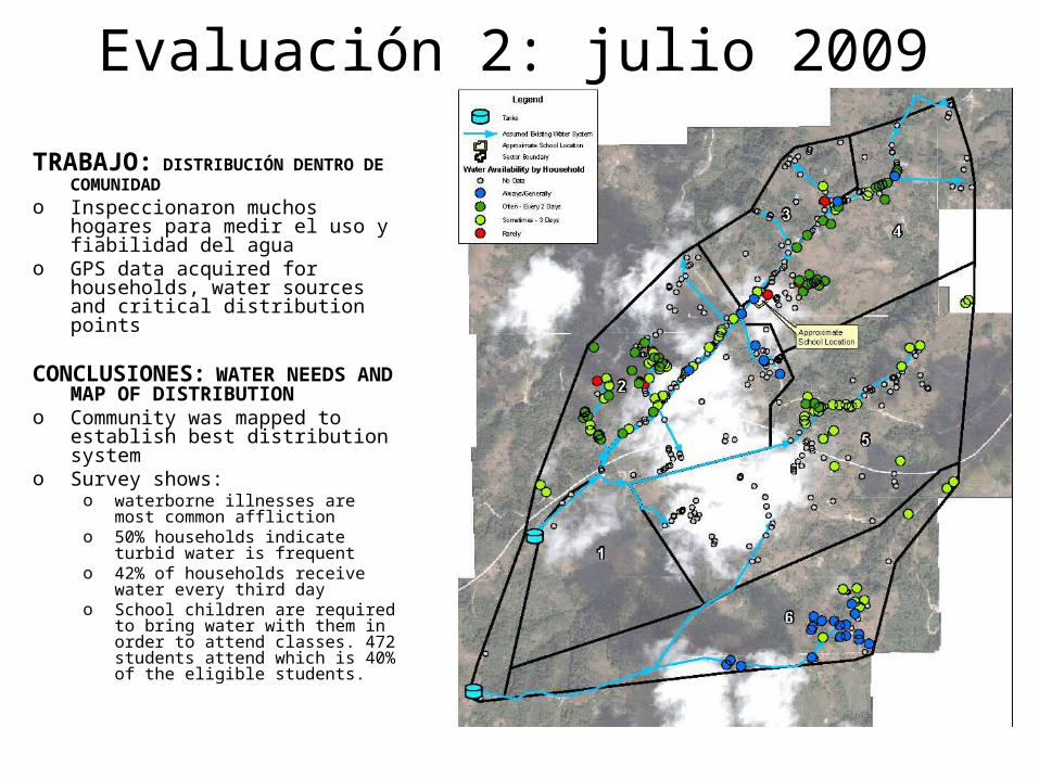
Evaluación 2: julio 2009
TRABAJO: DISTRIBUCIÓN DENTRO DE COMUNIDAD
o Inspeccionaron muchos hogares para medir el uso y fiabilidad del agua
o GPS data acquired for households, water sources and critical distribution points
CONCLUSIONES: WATER NEEDS AND MAP OF DISTRIBUTION
o Community was mapped to establish best distribution system
o Survey shows: o waterborne illnesses are most
common afflictiono 50% households indicate turbid
water is frequento 42% of households receive water
every third dayo School children are required to bring
water with them in order to attend classes. 472 students attend which is 40% of the eligible students.

Assessment 2: July 2009
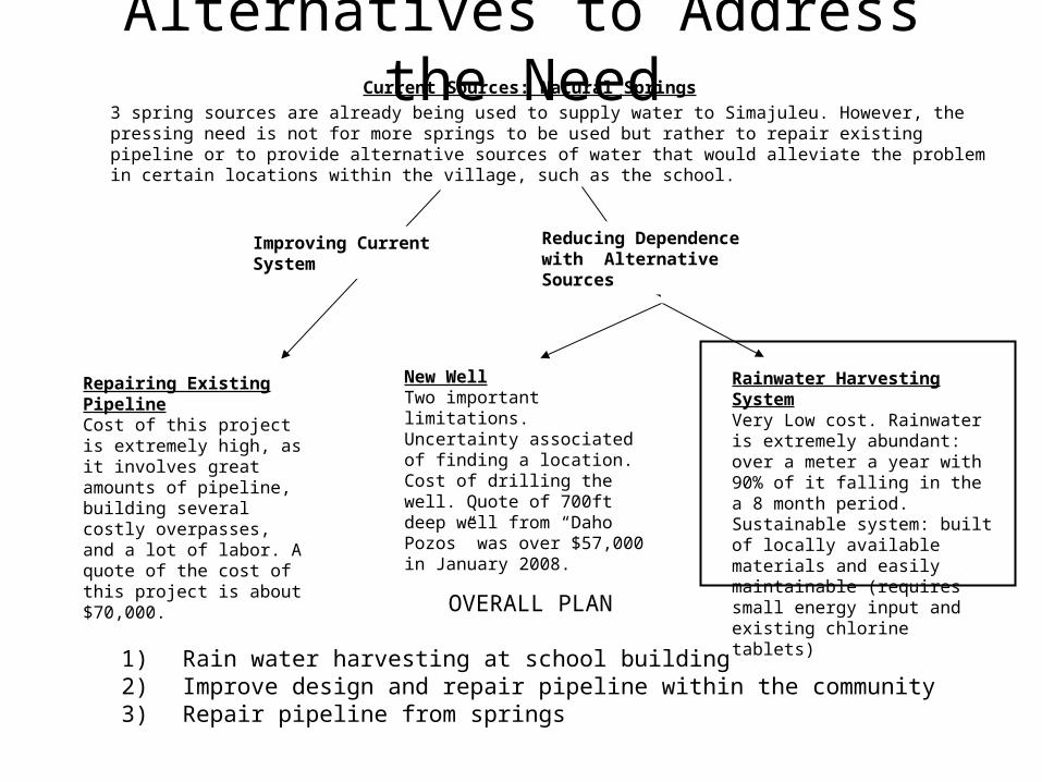
Alternatives to Address the NeedCurrent Sources: Natural Springs
3 spring sources are already being used to supply water to Simajuleu. However, the pressing need is not for more springs to be used but rather to repair existing pipeline or to provide alternative sources of water that would alleviate the problem in certain locations within the village, such as the school.
Repairing Existing PipelineCost of this project is extremely high, as it involves great amounts of pipeline, building several costly overpasses, and a lot of labor. A quote of the cost of this project is about $70,000.
New WellTwo important limitations. Uncertainty associated of finding a location. Cost of drilling the well. Quote of 700ft deep well from “Daho Pozos” was over $57,000 in January 2008.
Rainwater Harvesting SystemVery Low cost. Rainwater is extremely abundant: over a meter a year with 90% of it falling in the a 8 month period. Sustainable system: built of locally available materials and easily maintainable (requires small energy input and existing chlorine tablets)
Improving Current System Reducing Dependence with Alternative Sources
OVERALL PLAN
1) Rain water harvesting at school building2) Improve design and repair pipeline within the community3) Repair pipeline from springs

Quote to drill a well by Daho Pozos Inc.
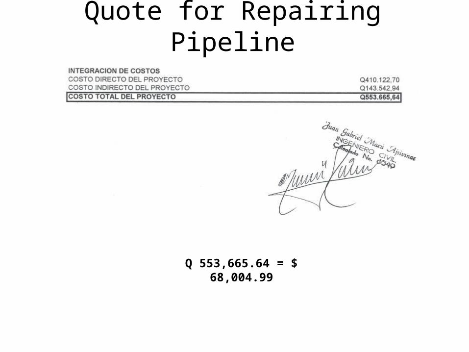
Quote for Repairing Pipeline
Q 553,665.64 = $ 68,004.99

Selection of School
WHY?
• Example of rain water harvesting system that could be replicated around village
• Large surface area will yield appreciable amounts of rainwater. Possibility of expansion.
• Ensure the supply goes to the most vulnerable members of the village, the children.
SCHOOL
WATER LINE
SCHOOL
ELEVATED TANK
HOW?
Elevated tank can be disconnected from main line and connected to our rain water catchment system:
• benefit community by reducing dependence on main line
• benefit school by having its own reliable water source

Water Demand Analysis
Collection, Consumption and Resulting Tank Level
0
20000
40000
60000
80000
100000
120000
140000
Aug Sept
OctNov
Dec Jan Feb
March
April
May JuneJuly
Month
Lite
rs
Gross Collection Total Consumption Tank Level
Aug 0.158 23.3 30004 45551 75556 29905 4534 34439 41117 41117 41117Sept 0.227 25.2 43107 65444 108551 29905 4904 34808 73743 114860 130000Oct 0.141 20.8 26776 40650 67426 29905 4047 33952 33474 148334 130000Nov 0.042 11.3 7976 12109 20084 29905 2199 32103 -12019 136315 117981Dec 0.017 8.2 3228 4901 8129 29905 1596 31500 -23371 112944 94610Jan 0.01 7.4 1899 2883 4782 29905 1440 31345 -26563 86382 68047Feb 0.01 6.2 1899 2883 4782 29905 1206 31111 -26329 60053 41718
March 0.012 6 2279 3460 5738 29905 1168 31072 -25334 34719 16385April 0.033 8.9 6267 9514 15781 29905 1732 31636 -15856 18863 529May 0.118 17.6 22408 34019 56428 29905 3425 33329 23098 41961 23627June 0.258 25.2 48994 74381 123376 29905 4904 34808 88567 130529 130000July 0.189 24.5 35891 54489 90380 29905 4767 34672 55708 186236 130000
Total 1.215 185 230729 350285 581013 358856 35921 394777 186236 - -
Tank Level [L]
Building 3 Collection [L]
Building 5 Collection
[L]Accumulation [L]
Collection/ Consumption diff.
[L]First Flush [L]
Total Consumption [L]
Rainfall [m]
Month
Consumption [L]
Gross Collection [L]
Rainy Days
TANK SPACE CONSTRAINTS 20*30*8 FEET CAPACITY 130,000 Liters
29905 Liters in 20 days Supply of 390 gallons/day 3.1L/day/student during dry season

Water Demand AnalysisSuggested Supply • 14L/day by U.N. standards for students: 5L/day
Rainwater Supply• Storage tank with 130,000L capacity 3.1L/day
This should satisfy their current and future needs because:
– School obtains about 900gallons/week or 1.5L/day from the main line which brings the total supply to 4.6L/day
– School requested 2.4L/day (300 gallons/day)
– System is conveniently expandable because:• Community will possess knowledge based on this project• School has more buildings to harvest rain water• School has more free space where tanks can be built and
connected to storage tank

System Overview

Street
building 1 Building 635'3" x 22'-10" 28' x 30'-7"
Building 2 15'-10" gutter to ground
128'-8" x 36'-9" Basketball court8'-8" gutter ground
Building 366'-10" x 30'-7"9' gutter to ground
Underground Tank Building 520'x30' 10' gutter to ground6' underground 32'x97'2'above
Building 469'-9" x 32'
Elevated Tank 9'-7" gutter to ground Portico Building 76'-8" 80'-5" x 30'-4"x 28-7" 10'-2" gutter to ground
Fence 9'-2" g to g
School Layout: Piping and Storage
First flush systemPumpPVC pipeTank
3
5

Determining Roof Flow RateCalculations based on the largest building used in collection
100 year storm has a rain intensity of 10.8 in/hr
2 22
. . ( ) 6.732 . 1552 10,448.1.
gal galR I RoofArea ft ft
hr ft hr
Flow Rate from Roof
3 2. . 10.8 . . 7.481 6.732
12 .
in ft gal galR I VolumetricConversion
hr in ft ft hr

Determining Gutter SizeRoof Flow rate: 10,448.1 gal/hr
Sections of Gutter: 8
Gutter Flow Rate: 1306.01 gal/hr
United States Uniform Plumbing Code
A gutter of 5” diameter with a 1/8” slope was chosen. Rectangular gutters of slightly
greater capacity are to be used.
Flow Rates in gal/hr given Gutter Diameter and Slope
Diameter of
Gutter Gutter Slope
1/16" 1/8" 1/4" 1/2"
3" 340 480 680 960
4" 720 1020 1440 2040
5" 1250 1760 2500 3540
6" 1920 2720 3840 5840
7" 2760 3900 5520 7800
8" 3980 5600 7960 1120

Calculating Downspout Size
• Using Bernoulli’s equation the fluid velocity of each downspout can be calculated.Bernoulli’s Equation
• Fluid Velocity based on shortest downspout with 4’’ of length
• Volumetric Flow Rate based on a 3”-diameter downspout and this velocity
• A downspout of 3” can drain 6846 gal/hr of rain, which exceeds the 2612 gal/hr required
g
vz
p
g
vz
p
22
22
22
21
11
sec63.4)12/4)(
sec2.32(22
212
ftft
ftgzv
sec227275.0)125.0(
sec63.4
322 ftftx
ftVAQ
hr
gal
hr
gal
hrx
ft
galx
ft261205.6120
sec360048.7
sec227275.0
3
3
A downspout of 3’’ or greater will be used

Calculating Pipe SizesManning’s Equation:
2/31/2k A
V Sn P
Slope [ft/ft] Q [gal/hr]
Pipe Diameter
[in]Pipe Radius
[ft]Pipe Area
[ft2]
Wetted Perimeter
[ft] n [] k []1/8th inch
1/6th inch
1/4th inch
(a/p)^2/
3 k/n1/8th inch
1/6th inch
1/4th inch
2 0.083 0.022 0.523 0.009 1.486 0.010 0.0140.0208
333 0.120165.111 1189.2 1373.2 1681.8
3 0.125 0.049 0.785 0.009 1.486 0.010 0.0140.0208
333 0.157165.111 3506.3 4048.7 4958.6
4 0.167 0.087 1.047 0.009 1.486 0.010 0.0140.0208
333 0.191165.111 7551.2 8719.4
10679.1
5 0.208 0.136 1.308 0.009 1.486 0.010 0.0140.0208
333 0.221165.111
13691.3
15809.3
19362.4
6 0.250 0.196 1.570 0.009 1.486 0.010 0.0140.0208
333 0.250165.111
22263.6
25707.7
31485.4
4” diameter pipe at a slope of ¼” will be used
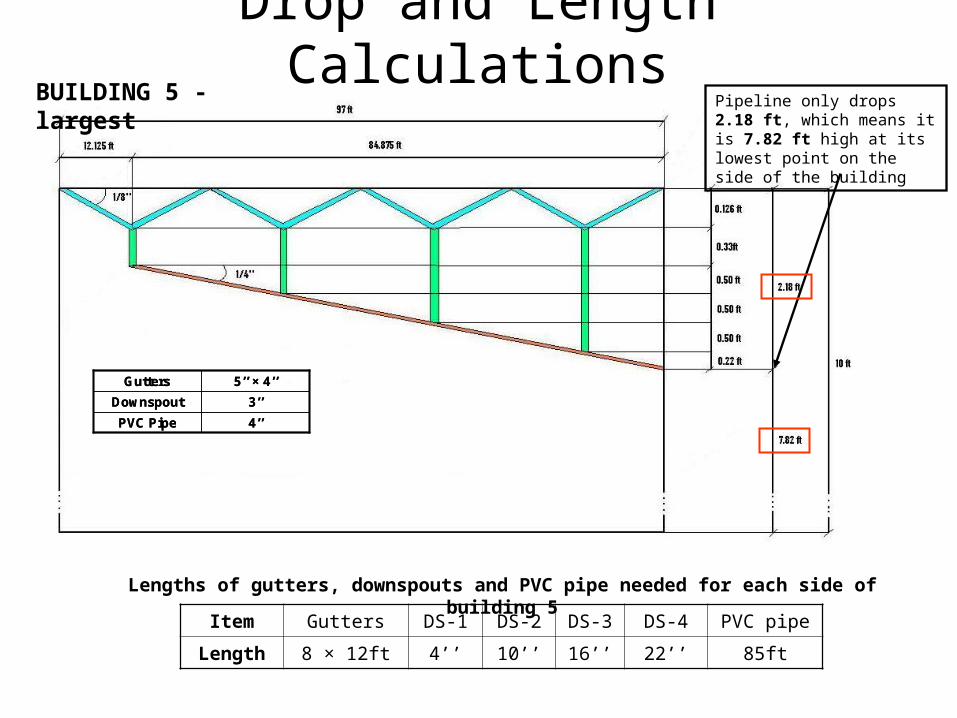
Drop and Length CalculationsPipeline only drops 2.18 ft, which means it is 7.82 ft high at its lowest point on the side of the building
Lengths of gutters, downspouts and PVC pipe needed for each side of building 5
Item Gutters DS-1 DS-2 DS-3 DS-4 PVC pipe
Length 8 × 12ft 4’’ 10’’ 16’’ 22’’ 85ft
BUILDING 5 - largest
4’’PVC Pipe
3’’Downspout
5’’ × 4’’Gutters
4’’PVC Pipe
3’’Downspout
5’’ × 4’’Gutters

Drop and Length CalculationsPipeline only drops 1.6 ft, which means it is 7.4 ft high at its lowest point on the side of the building
Item Gutters DS-1 DS-2 DS-3 PVC pipe
Length 6 × 11ft = 66ft 4’’ 9.5’’ 15’’ 56ft
BUILDING 3 - smallest
Lengths of gutters, downspouts and PVC pipe needed for each side of building 3
4’’PVC Pipe
3’’Downspout
5’’ × 4’’Gutters
4’’PVC Pipe
3’’Downspout
5’’ × 4’’Gutters

• 4 first flush systems, at each side of the two buildings
• For the first flush system, we are using a necessary first flush approximation of 10 gallons / 1000 square feet, which means we’re flushing the first 0.407mm of rain off the roof.
• The areas of our roofs are: Building 3: Building 5: 66'10” x 30'7” = 2043.986 ft2 97' x 32' = 3104 ft2
• These are the minimum amounts that can be flushed to effectively eliminate contaminates in the water
• Flush 11 gal from each side of Building 3 and 16 gal from each side of Building 5 • We will use barrels and piping that would add up to this volumetric capacity
mm=in
mm
ft
in
gal
ft
ft
gal0.407
1
25.4
1
12
1
.13368
1000
10 3
2
22
102044 20.44
1000
galft = gal
ft
First Flush Systems
22
103104 31.04
1000
galft = gal
ft

First Flush Diagram

Gutter Attachment to Fascia
Gutters will be bolted directly to the corrugated roof.
To eliminate rain water from overshooting our gutters all will be placed with a minimum of 3” of overhang.

Piping Plan
First flush systemPump4 inch PVC pipeTank2 inch PVC pipe
1
2
4
5 3
6
3
5
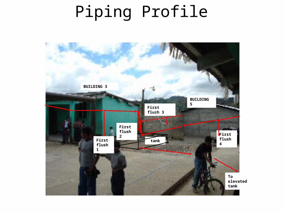
Piping Profile
tankFirst flush 1
First flush 4
To elevated tank
First flush 3
BUILDING 5
BUILDING 3
First flush 2

Length of Piping and Gutters
Section Length of Pipe (ft)
1 (two sides of building 3) 112
2 (end of building 3) 40
3 (two sides of building 5) 170
4 (end of building 5) 50
5 (first flush to tank-horizontal) 90
5(first flush to tank - vertical) 15
TOTAL 4’’ PVC PIPE 477
6 (underground to elevated tank- horizontal) 120
6 (underground to elevated tank-vertical) 15
TOTAL 2’’ PVC PIPE 135
Section Length (ft) of 5’’ Gutter Length (ft) of 3’’ Downspouts
Two sides of building 3 132 (12 by 11ft) 4.75
Two sides of building 5 192 (16 by 12ft) 8.6
TOTAL 324 13.35

Storage Tank: ComparisonTank Type Advantages Disadvantages
Cement Cost: Would be far cheaper than the multiple polytanks required.
Construction: Tank would require 2 weeks of construction time if everything went smoothly.
Construction: The village already has a tank of near identical size and construction, so maintenance and construction methods are known by the locals.
Construction: Tank construction would require the dependence on skilled mason's from the village.
Water Quality: The basic nature of cement would help neutralize any acidic nature inherent in the rainwater.
Permanent: Once constructed this tank would be permanent.
Polytank Construction: Tanks are already constructed reducing implementation time.
Cost: Polytanks would be much more than double the cost of a single concrete tank.
Flexible: The Tanks are flexible and are able to be moved in The future if needed.
Size limitations: Polytanks are not manufactured in 100,000 L size so multiple tanks would be necessary, further raising costs.
Degradation: Polytanks are susceptible to UV degradation decreasing their lifetime.

Tank Designs
Dimensions

Outside View in PerspectiveApproximate Scale

Elements in Perspective Approximate Scale

Plane View – Exact Scale
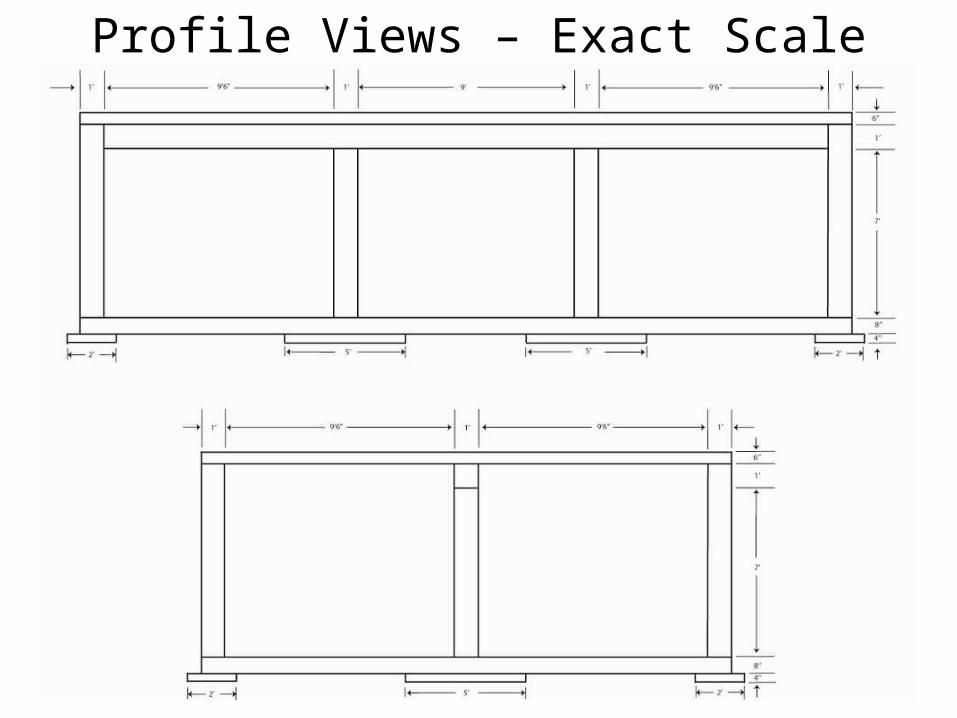
Profile Views – Exact Scale

Tank Designs
Rebar Details

Footings
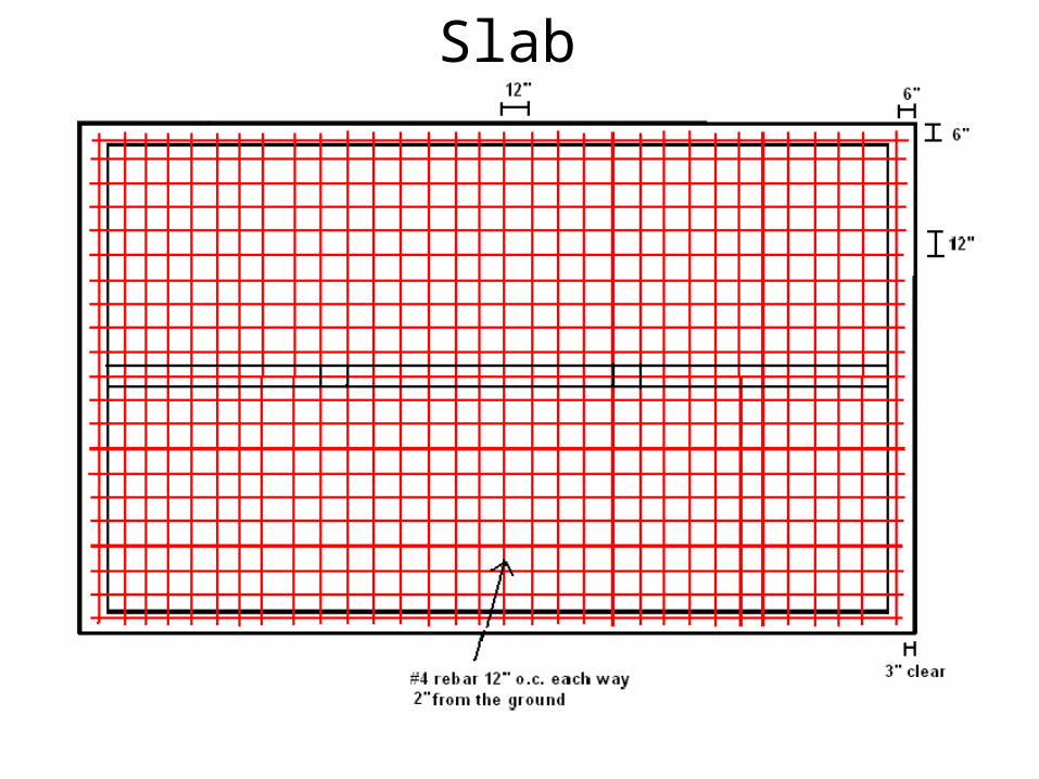
Slab

Walls and Column

Slab, Beam and Cap

Cap

Pump System View
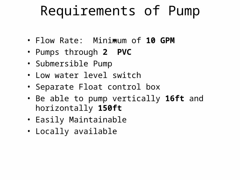
Requirements of Pump
• Flow Rate: Minimum of 10 GPM• Pumps through 2” PVC• Submersible Pump• Low water level switch• Separate Float control box• Be able to pump vertically 16ft and horizontally 150ft• Easily Maintainable• Locally available
Determining Desired Flow Rate
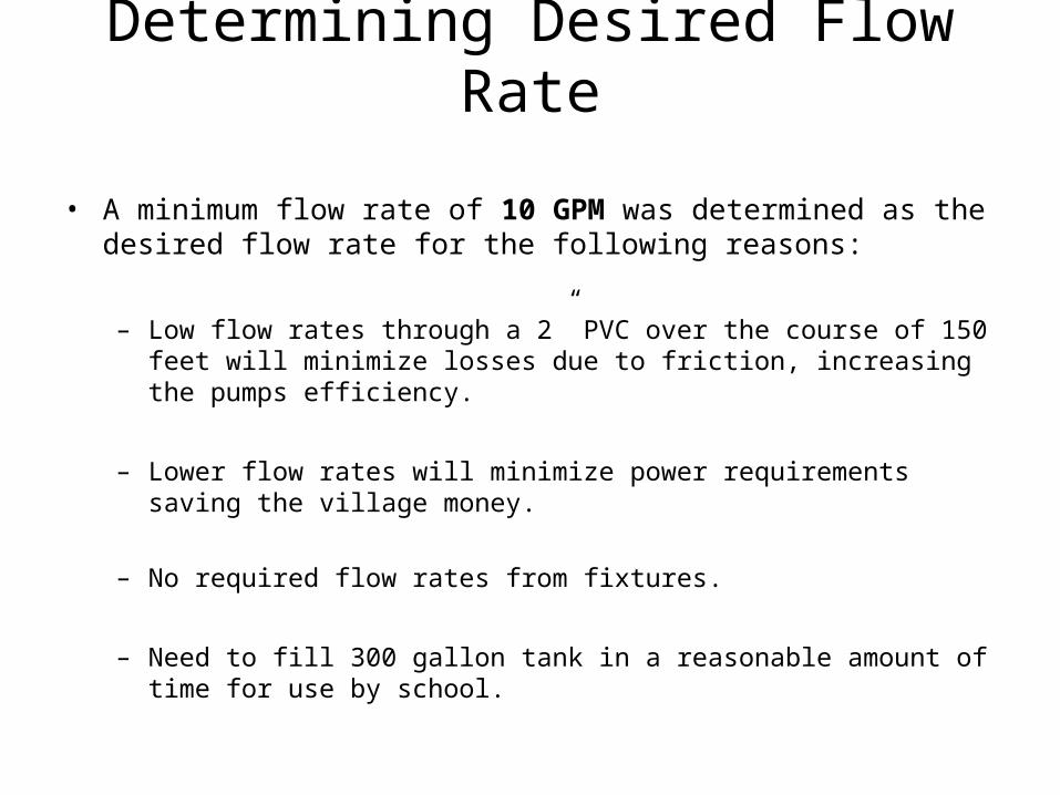
• A minimum flow rate of 10 GPM was determined as the desired flow rate for the following reasons:
– Low flow rates through a 2” PVC over the course of 150 feet will minimize losses due to friction, increasing the pumps efficiency.
– Lower flow rates will minimize power requirements saving the village money.
– No required flow rates from fixtures.
– Need to fill 300 gallon tank in a reasonable amount of time for use by school.
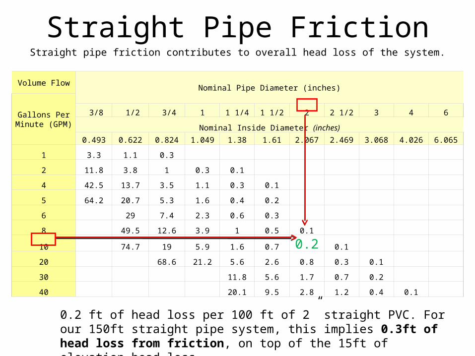
Straight Pipe FrictionStraight pipe friction contributes to overall head loss of the system.
Volume FlowNominal Pipe Diameter (inches)
Gallons Per Minute (GPM)
3/8 1/2 3/4 1 1 1/4 1 1/2 2 2 1/2 3 4 6
Nominal Inside Diameter (inches)
0.493 0.622 0.824 1.049 1.38 1.61 2.067 2.469 3.068 4.026 6.065
1 3.3 1.1 0.3
2 11.8 3.8 1 0.3 0.1
4 42.5 13.7 3.5 1.1 0.3 0.1
5 64.2 20.7 5.3 1.6 0.4 0.2
6 29 7.4 2.3 0.6 0.3
8 49.5 12.6 3.9 1 0.5 0.1
10 74.7 19 5.9 1.6 0.7 0.2 0.1
20 68.6 21.2 5.6 2.6 0.8 0.3 0.1
30 11.8 5.6 1.7 0.7 0.2
40 20.1 9.5 2.8 1.2 0.4 0.1
0.2 ft of head loss per 100 ft of 2” straight PVC. For our 150ft straight pipe system, this implies 0.3ft of head loss from friction, on top of the 15ft of elevation head loss.
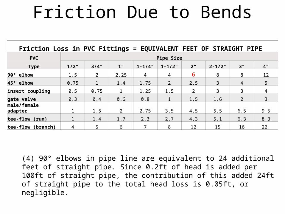
Friction Due to Bends
Friction Loss in PVC Fittings = EQUIVALENT FEET OF STRAIGHT PIPE PVC Pipe Size
Type 1/2" 3/4" 1" 1-1/4" 1-1/2" 2" 2-1/2" 3" 4"
90° elbow 1.5 2 2.25 4 4 6 8 8 12
45° elbow 0.75 1 1.4 1.75 2 2.5 3 4 5
insert coupling 0.5 0.75 1 1.25 1.5 2 3 3 4
gate valve 0.3 0.4 0.6 0.8 1 1.5 1.6 2 3
male/female adapter 1 1.5 2 2.75 3.5 4.5 5.5 6.5 9.5
tee-flow (run) 1 1.4 1.7 2.3 2.7 4.3 5.1 6.3 8.3
tee-flow (branch) 4 5 6 7 8 12 15 16 22
(4) 90° elbows in pipe line are equivalent to 24 additional feet of straight pipe. Since 0.2ft of head is added per 100ft of straight pipe, the contribution of this added 24ft of straight pipe to the total head loss is 0.05ft, or negligible.

Power Calculations
• Total Dynamic Head (TDH)
Total Dynamic Head
TDH Components Quantity Head loss [ft]
Vertical lift 16 ft 16
Straight Pipe Friction 150 ft 0.30
90 degree elbow 4 0.05
Check Valve 1 0.6
Total TDH 16.95
• Minimum Power Requirements
[ ]* [ ] 10 *16.95[ ] 0.08 0.1
2178 2178
flowrate GPM TDH ft GPM ftPower hp hp
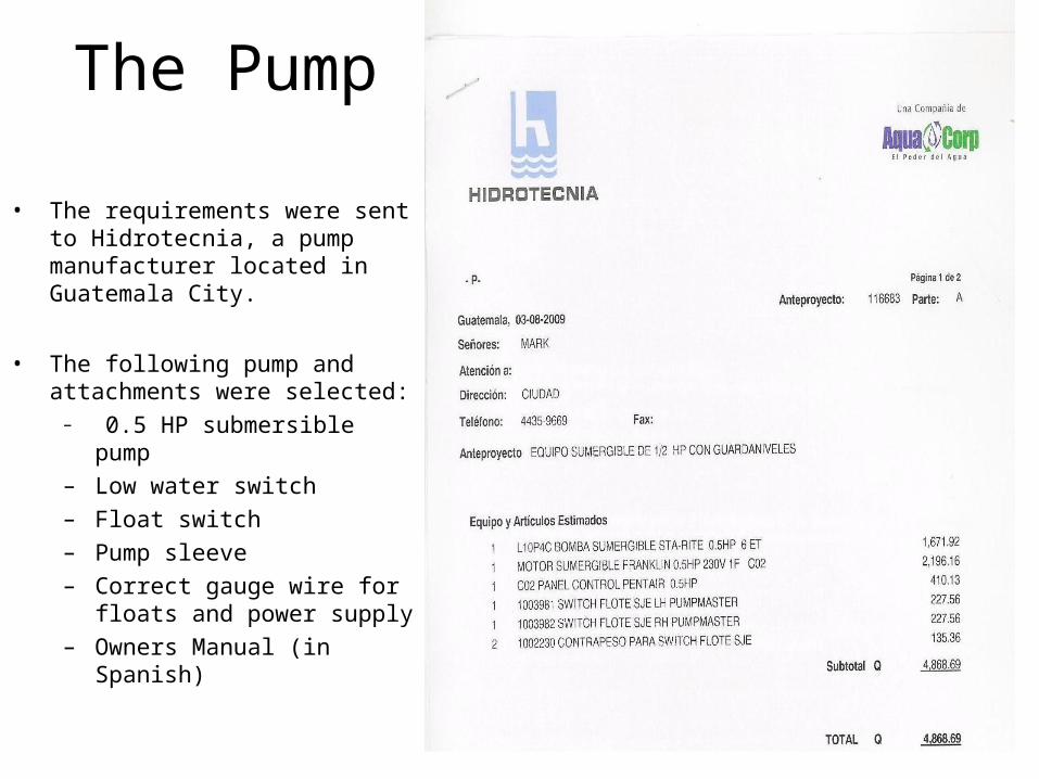
The Pump
• The requirements were sent to Hidrotecnia, a pump manufacturer located in Guatemala City.
• The following pump and attachments were selected:
– 0.5 HP submersible pump– Low water switch– Float switch– Pump sleeve– Correct gauge wire for floats
and power supply– Owners Manual (in Spanish)
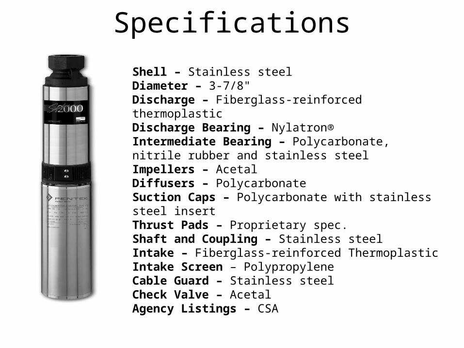
Specifications
Shell – Stainless steelDiameter – 3-7/8"Discharge – Fiberglass-reinforced thermoplasticDischarge Bearing – Nylatron®Intermediate Bearing – Polycarbonate, nitrile rubber and stainless steelImpellers – AcetalDiffusers – PolycarbonateSuction Caps – Polycarbonate with stainless steel insertThrust Pads – Proprietary spec.Shaft and Coupling – Stainless steelIntake – Fiberglass-reinforced ThermoplasticIntake Screen – PolypropyleneCable Guard – Stainless steelCheck Valve – AcetalAgency Listings – CSA

Pump Placement
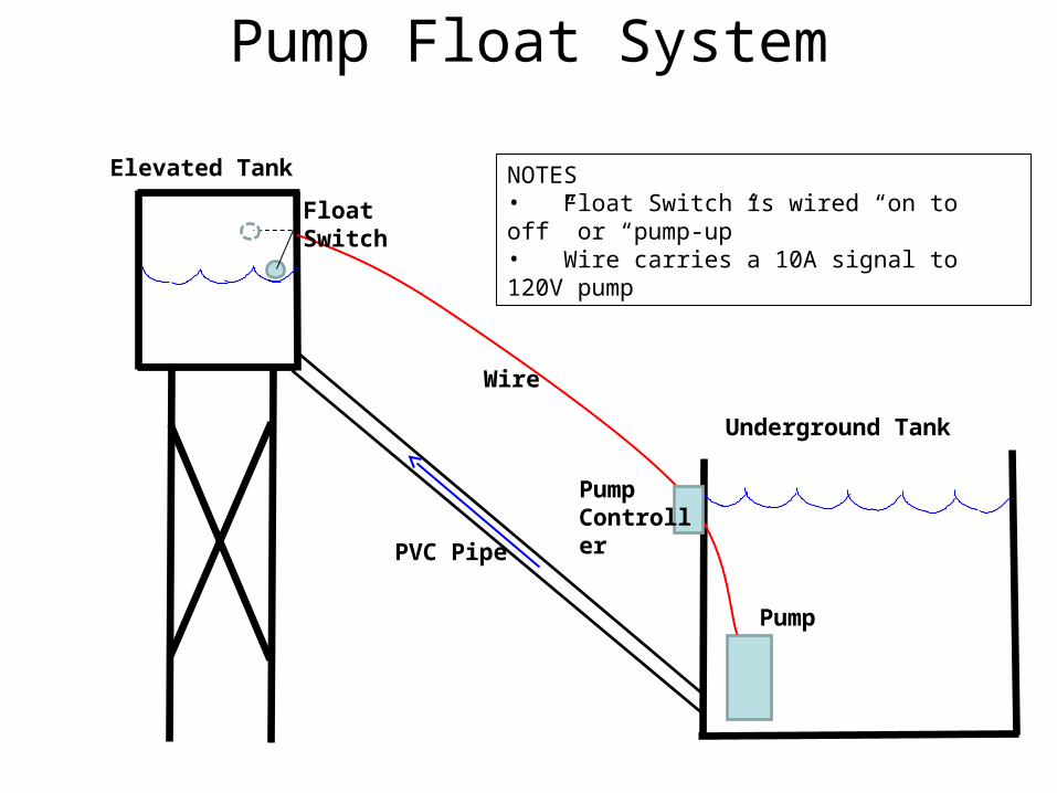
Pump Float System
Underground Tank
Pump
Elevated Tank
PVC Pipe
Wire
Float Switch
NOTES• Float Switch is wired “on to off” or “pump-up”• Wire carries a 10A signal to 120V pump
PumpController

ChlorinationCTI 8 Water Chlorinator
Compatible Technology InternationalCost: $100
BEST SET-UP WOULD BE AFTER
ELEVATED TANK
Requirements Our system
Gravity Fed enclosed system
Gravity Fed after elevated tank
Flow rates:
2-20gal/min
2 gal/min at hand-washing stations
3’’ or 4’’ PVC ¾ ‘’ but can be adapted
2.5’’ diameter chlorine tablets
Same, provided by Municipalidad
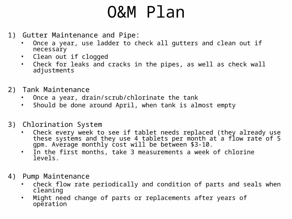
O&M Plan1) Gutter Maintenance and Pipe:
• Once a year, use ladder to check all gutters and clean out if necessary• Clean out if clogged • Check for leaks and cracks in the pipes, as well as check wall adjustments
2) Tank Maintenance • Once a year, drain/scrub/chlorinate the tank• Should be done around April, when tank is almost empty
3) Chlorination System • Check every week to see if tablet needs replaced (they already use these
systems and they use 4 tablets per month at a flow rate of 5 gpm. Average monthly cost will be between $3-10.
• In the first months, take 3 measurements a week of chlorine levels.
4) Pump Maintenance• check flow rate periodically and condition of parts and seals when cleaning• Might need change of parts or replacements after years of operation

Community Agreement