NOTE: SI/200 US - BPT Group mex_si200_us 24059012 02_09.pdf · - Aumente la distancia que separa el...
8
1 SI/200 ENTRANCE SELECTOR This unit permits the selection of two entry panels and is configured to crea- te the following systems: • Single or multi-family systems with several entrances using the same number of selectors as there are entry panels minus one. • Residential systems using the unit as a block selector. Operating characteristics • Protection of any connections instal- led and management of the “engaged” signal, irrespective of whether the unit is used as a selector for several entry panels or as a block selector in resi- dential systems. The protection mechanism is disabled under the following conditions: - approx. 2 minutes after the call; - when the handset is replaced (SW1 jumper connected); - permanently (SW2 jumper connec- ted). • The selector is equipped with an amplifier which regenerates the call signal. • Possibility of connecting up to three internal units to the same call. • Possibility of trading the origin of an external call by means of different tones which correspond to two diffe- rent entry panels. To enable this function, connect termi- nal 8A of SI/200 selector to terminal 8A on the power supplier installed (A/200, A/241, etc.), figure 3. In this case, connections cannot be made for calls originating from internal floor landings. Function of each terminal, figure 1 Terminal block B (to power supplier or preceding selector) 5 – 11V supply voltage 21 + to entry panel 8 call 1 common 8A call 2 common 11 audio to receiver 12 audio to entry panel 23 input 14V AC 13 door release solenoid 16 0V AC 24 engaged signal input Terminal block E (to entry panel no. 1) 5 – 11V supply voltage 21 + to entry panel 8 call common 11 audio to receiver 12 audio to entry panel 23 output 14V AC 13 door release solenoid 16 0V AC 24 engaged signal output RS reset ( 1 ) E audio enable ( 1 ) Functions for combined (audio and video entry systems) installa- tions. Terminal block F (to entry panel no. 2 or subsequent selector) 5 – 11V supply voltage 21 + to entry panel 8 call common 11 audio to receiver 12 audio to entry panel 23 output 14V AC 13 door release solenoid 16 0V AC 24 engaged signal output Terminal block G (services) 1 call 1 input 2 call 2 input 4 engaged signal output (for resi- dential systems) 5 general reset 6 enable output Terminal block H (services) 1 call 1 output 2 call 2 output SW jumpers functions, figure 1 (in ON position) SW1 resetting of engaged entry panels by replacing the hand- set. SW2 deactivation of call protection and engaged signal. NOTE. The selector is supplied with SW1 jumper wired in. When A/241 power supplier are used (1+n installations), the SW1 jumper must be connected, figure 1. Technical features • Supply voltage: 11 V DC. • Current demand: 45 mA max. (5 mA quiescent). • Working temperature range: from 0 °C to +35 °C. • Dimensions: 8 DIN units, low profile module, figure 2. The power supplier can be installed without terminal covers into boxes provided with DIN rail (EN 50022). Dimensions are shown in figure 2A. It can also be surface mounted, using the DIN rail supplied, but fitted with terminal covers. Dimensions are shown in figure 2B. DISPOSAL Do not litter the environment with packing material: make sure it is dis- posed of according to the regulations in force in the country where the prod- uct is used. When the equipment reaches the end of its life cycle, take measures to ensure it is not discarded in the envi- ronment. The equipment must be disposed of in compliance with the regulations in force, recycling its component parts wherever possible. Components that qualify as recyclable waste feature the relevant symbol and the material’s abbreviation. SI/200 US 02.2009/2405-9012 5 21 8 11 12 23 13 ON SW1 OFF 5 21 8 11 12 23 13 16 24 RS E E F 5 21 8 8A 11 12 23 13 16 24 B SW2 16 24 1 2 1 2 4 5 G 6 H SW 1 43,5 45 7,5 57 140 106 A B 64,5 140 145 2 BPT S.p.A. Via Cornia, 1 33079 Sesto al Reghena-PN-Italy [email protected] – www.bpt.it EN INSTALLATION INSTRUCTIONS NOTE: This equipment has been tested and found to com- ply with the limits for a Class B digital device, pursuant to Part 15 of the FCC Rules. These limits are designed to pro- vide reasonable protection against harmful interference in a residential installation. This equipment generates, uses and can radiate radio frequency energy and, if not installed and used in accordance with the instruc- tions, may cause harmful interference to radio communications. However, there is no guarantee that interference will not occur in a par- ticular installation. If this equipment does cause harmful interference to radio or television reception, which can be determined by turning the equipment off and on, the user is encouraged to try to correct the interference by one or more of the following measures: - Reorient or relocate the receiving antenna. - Increase the separation between the equipment and receiver. - Connect the equipment into an outlet on a circuit different from that to which the receiver is connected. - Consult the dealer or an experienced radio/TV technician for help. DIMENSIONS IN MILLIMETRES DIMENSIONES EN MILIMETROS
Transcript of NOTE: SI/200 US - BPT Group mex_si200_us 24059012 02_09.pdf · - Aumente la distancia que separa el...
1
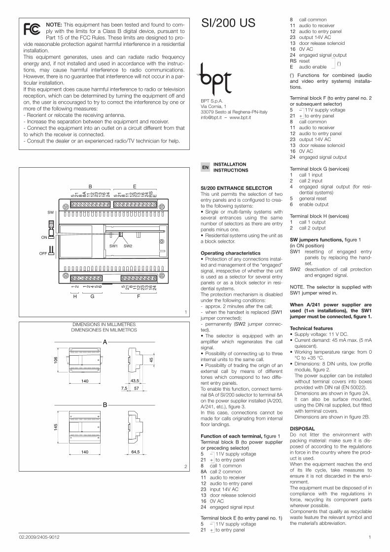
SI/200 ENTRANCE SELECTORThis unit permits the selection of twoentry panels and is configured to crea-te the following systems:• Single or multi-family systems withseveral entrances using the samenumber of selectors as there are entrypanels minus one.• Residential systems using the unit asa block selector.
Operating characteristics• Protection of any connections instal-led and management of the “engaged”signal, irrespective of whether the unitis used as a selector for several entrypanels or as a block selector in resi-dential systems.The protection mechanism is disabledunder the following conditions:- approx. 2 minutes after the call;- when the handset is replaced (SW1jumper connected);- permanently (SW2 jumper connec-ted).• The selector is equipped with anamplifier which regenerates the callsignal.• Possibility of connecting up to threeinternal units to the same call.• Possibility of trading the origin of anexternal call by means of differenttones which correspond to two diffe-rent entry panels.To enable this function, connect termi-nal 8A of SI/200 selector to terminal 8Aon the power supplier installed (A/200,A/241, etc.), figure 3.In this case, connections cannot bemade for calls originating from internalfloor landings.
Function of each terminal, figure 1Terminal block B (to power supplieror preceding selector)5 – 11V supply voltage21 + to entry panel8 call 1 common8A call 2 common11 audio to receiver12 audio to entry panel23 input 14V AC13 door release solenoid16 0V AC24 engaged signal input
Terminal block E (to entry panel no. 1)5 – 11V supply voltage21 + to entry panel
8 call common11 audio to receiver12 audio to entry panel23 output 14V AC13 door release solenoid16 0V AC24 engaged signal outputRS reset (1)E audio enable
(1) Functions for combined (audioand video entry systems) installa-tions.
Terminal block F (to entry panel no. 2or subsequent selector)5 – 11V supply voltage21 + to entry panel8 call common11 audio to receiver12 audio to entry panel23 output 14V AC13 door release solenoid16 0V AC24 engaged signal output
Terminal block G (services)1 call 1 input2 call 2 input4 engaged signal output (for resi-
dential systems)5 general reset6 enable output
Terminal block H (services)1 call 1 output2 call 2 output
SW jumpers functions, figure 1(in ON position)SW1 resetting of engaged entry
panels by replacing the hand-set.
SW2 deactivation of call protectionand engaged signal.
NOTE. The selector is supplied withSW1 jumper wired in.
When A/241 power supplier areused (1+n installations), the SW1jumper must be connected, figure 1.
Technical features• Supply voltage: 11 V DC.• Current demand: 45 mA max. (5 mA
quiescent).• Working temperature range: from 0
°C to +35 °C.• Dimensions: 8 DIN units, low profile
module, figure 2.The power supplier can be installedwithout terminal covers into boxesprovided with DIN rail (EN 50022).Dimensions are shown in figure 2A. It can also be surface mounted,using the DIN rail supplied, but fittedwith terminal covers.Dimensions are shown in figure 2B.
DISPOSALDo not litter the environment withpacking material: make sure it is dis-posed of according to the regulationsin force in the country where the prod-uct is used.When the equipment reaches the endof its life cycle, take measures toensure it is not discarded in the envi-ronment.The equipment must be disposed of incompliance with the regulations inforce, recycling its component partswherever possible.Components that qualify as recyclablewaste feature the relevant symbol andthe material’s abbreviation.
SI/200 US
02.2009/2405-9012
5 21 8 11 12 23 13
ON
SW1OFF
5 21 8 11 12 23 13 16 24 RS E
E
F
5 21 8 8A 11 12 23 13 16 24
B
SW2
16 241 2 1 2 4 5
G
6
H
SW
1
43,5
45
7,5 57140
106
A
B
64,5140
145
2
BPT S.p.A.Via Cornia, 133079 Sesto al [email protected] – www.bpt.it
ENINSTALLATIONINSTRUCTIONS
NOTE: This equipment has been tested and found to com-ply with the limits for a Class B digital device, pursuant toPart 15 of the FCC Rules. These limits are designed to pro-
vide reasonable protection against harmful interference in a residentialinstallation.This equipment generates, uses and can radiate radio frequencyenergy and, if not installed and used in accordance with the instruc-tions, may cause harmful interference to radio communications.However, there is no guarantee that interference will not occur in a par-ticular installation.If this equipment does cause harmful interference to radio or televisionreception, which can be determined by turning the equipment off andon, the user is encouraged to try to correct the interference by one ormore of the following measures:- Reorient or relocate the receiving antenna. - Increase the separation between the equipment and receiver.- Connect the equipment into an outlet on a circuit different from thatto which the receiver is connected.- Consult the dealer or an experienced radio/TV technician for help.
DIMENSIONS IN MILLIMETRESDIMENSIONES EN MILIMETROS

2
(1) Funciones para equipos mixtos(audiointercomunicador y monitores).
Bornera F (a la placa exterior n° 2 o alselector siguiente)5 – 11V alimentación21 + placa exterior8 común llamada11 audio al derivado interno12 audio a la placa exterior23 salida 14VAC13 cerradura eléctrica16 0VAC24 salida señalización de ocupado
Bornera G (servicios)1 entrada llamada 12 entrada llamada 24 salida señalización de ocupado
(para equipos residenciales)5 reinicializar general6 salida habilitación
Bornera H (servicios)1 salida llamada 12 salida llamada 2
Funciones de los puentes SW (fig.1) (en posicion ON)SW1 restablecimiento de las placas
exteriores ocupadas al colgar elauricular
SW2 desactivación de la protecciónde llamadas y señal de ocupa-do.
NOTA. El selector se provee con elpuente SW1 insertado.
Si se emplea el alimentador A/241(equipos 1+n), se debe montar elpuente SW1 (fig. 1).
Características técnicas• Alimentación: 11VDC.• Consumo: 45 mA máx. (5 mA en
reposo).• Temperatura de funcionamiento: de
0 °C a +35 °C.• Dimensiones: módulo de 8 unidades
bajo para guía DIN (fig. 2).
El aparato se puede instalar, sin cubre-bornes, en cajas dotadas de guías DIN(EN 50022).Por las dimensiones consultar la fig.2A.También se puede aplicar a la paredcon cubrebornes, utilizando la guíaDIN que se entrega de serie.Por las dimensiones consultar la fig.2B.
ELIMINACIONComprobar que no se tire al me-dioambiente el material de emba-laje,sino que sea eliminado conforme a lasnormas vigentes en el país donde seutilice el producto.Al final del ciclo de vida del aparatoevítese que éste sea tirado almedioambiente.La eliminación del aparato debe efec-tuarse conforme a las normas vigentesy privilegiando el reciclaje de suspartes componentes.En los componentes, para los cualesestá prevista la eliminación con recicla-je, se indican el símbolo y la sigla delmaterial.
SELECTOR DE ENTRADA SI/200Este aparato permite seleccionar dosplacas exteriores y puede utilizarsepara la realización de los siguientestipos de equipos: • Equipos mono o plurifamiliares convarias entradas, utilizando un númerode selectores igual al de placas exte-riores menos uno.• Equipos residenciales, utilizando elaparato como selector de bloque deviviendas.
Característicasfuncionales del selector• Protección de eventuales conexio-nes en curso y control de la señaliza-ción de ocupado, ya sea que se lo uti-lice como selector para varias placasexteriores o como selector de bloqueen equipos residenciales.La protección se inhabilita de lassiguientes maneras:- aproximadamente 2 minutos de-spués de la llamada;- cuando se cuelga el auricular (puen-te SW1 montado);- de forma permanente (puente SW2montado).• El selector está dotado de un ampli-ficador que regenera la señal de llama-da.• Posibilidad de conectar a una mismallamada hasta 3 derivados internos.• Posibilidad de reconocer la placaexterior de la cual proviene la llamada,mediante nota diferenciada para dosentradas.Para obtener esta función, conectar elborne 8A del selector SI/200 con elborne 8A del alimentador utilizado(A/200, A/241, etc.), fig. 3.En este caso no es posible realizar laconexión para una posible llamadadesde el rellano.
Funciones de los bornes (fig. 1)Bornera B (al alimentador o al selectoranterior)5 – 11V alimentación21 + placa exterior8 común llamada 18A común llamada 211 audio al derivado interno12 audio a la placa exterior23 entrada 14VAC13 cerradura eléctrica16 0VAC24 entrada señalización de ocupado
Bornera E (a la placa exterior n° 1)5 – 11V alimentación21 + placa exterior8 común llamada11 audio al derivado interno12 audio a la placa exterior23 salida 14VAC13 cerradura eléctrica16 0VAC24 salida señalización de ocupadoRS reinicializar (1)E habilitación audio
E
SI/200
5218111223131624RSE
F
B G
H
521
8111223131624
52188A111223131624
12456
12
A/200N
B
C
+B52188A11
589
122316NOCNC A
L N
3
E INSTRUCCIONESPARA LA INSTALACION
LEVITONLEVITON S de RL de CVLAGO TANA 43 Col HUICHAPAN CP11290MEXICO DF Tel 5082 1040
LEA Y CONSERVE ESTEINSTRUCTIVO
NOTA: este equipo ha sido ensayado y declarado conforme alos límites establecidos para un dispositivo digital de Clase B,
de acuerdo con el Apartado 15 de las Normas FCC. Estos límites hansido diseñados para ofrecer una protección razonable contra interfe-rencias perjudiciales en una instalación residencial.Este equipo genera, utiliza y puede emitir energía de radiofrecuencia y, si nose instala y utiliza conforme a las instrucciones, puede crear interferenciasperjudiciales para las radiocomunicaciones. Sin embargo, no se garantizaque no se produzcan interferencias en una instalación concreta.Si este equipo crea interferencias perjudiciales para la recepción deradio o televisión, lo cual se puede comprobar apagando y encendien-do el equipo, se recomienda al usuario que intente corregir la interfe-rencia adoptando una o varias de las siguientes medidas:- Modifique la orientación o la posición de la antena receptora. - Aumente la distancia que separa el equipo del receptor.- Conecte el equipo a un tomacorriente de un circuito diferente de aquelal que está conectado el receptor.- Solicite la asistencia de su distribuidor o de un técnico de radio/TVcualificado.

3
INSTALLATION WIRING DIAGRAMSESQUEMAS DE INSTALACIONES
C : 0,5 mm2
Max. 3
CP
A : 1 mm2
B : 0,5 mm2
150 m 100 m
C : 1 mm2
CP: Personal door-bell button.Pulsador de llamada desde el rellano.
AE: Auxiliary door-lock release button.Pulsador auxiliar abrepuerta.
WIRE CROSS-SECTIONSECCION DE LOS CONDUCTORES

5681114
DE
12
MC/…
TMP/…+TTS/…+
MVA/100.01+MC/…
AE
12V
E
SI/200
F
BG
H
521
8111223131624
12456
12
34 2 1
34
38A 9 8 54
2 1
B B B B CB
BAAABBBBB
2
MVA/100.01
561719-+
C1234
B
SW2
SW3
1 2
SW
B
AE
12V
AAABBBBB
1
HA/2005
218
2
3
111214
HPC/1+HA/200+…KHPS+…HPP/6+…HTS+KHSO
4
1B
KHSO5218111223131624RSE
A/200RN
C589
A
CP
YC/200
5789
C
2
521
88A111223131624
C
XC/200
5789
1
CPC/200C
5789
+B52188A11122316NOCNC
B
L N
4
SE 7511.4 UL
SINGLE OR MULTI-FLAT INSTALLA-TION WITH 2 ENTRANCES.
EQUIPO MONO O MULTIFAMILIARCON 2 ENTRADAS.

C/200 3
34
9 8 54
2 1 5 21 8 11 12 NC NO 16
BB CBB
CP
8A
SE 7512.4-B UL
B
C589
A/200N
+B52188A11122316NOCNC A
C5789
1
CP
C
XC/200
5789
BB
YC/200
5789
C
2CP
B
L N
5
SE 7512.4 UL
SINGLE OR MULTI-FLAT INSTALLA-TION WITH 3 ENTRANCES.
EQUIPO MONO O MULTIFAMILIARCON 3 ENTRADAS.
SE 7512.4-A UL

5681114
DE
12
MC/…
TMP/…+TTS/…+
MVA/100.01+MC/…
AE
12V
E
SI/200
F
BG
H
521
8111223131624
12456
12
34 2 1
BAAABBBBB
3
MVA/100.01
561719-+
SW2
SW3
1 2
SW
4 3 2 1
4 3 2 1
E
SI/200
F
BG
H
521
8111223131624
521
88A111223131624
12456
12
15 21 8 11 2312
NONC13 164 3 2 1
4 3 2 1
SE 7512.4-A UL
B
AS/200
1623+B521
A
1 2
SW
2
521
88A111223131624
AE
12V
AAABBBBB
2
HA/2005
218
2
3
111214
HPC/1+HA/200+…KHPS+…HPP/6+…HTS+KHSO
4
1B
AE
12V
AAABBBBB
1
HA/2005
218
2
3
111214
HPC/1+HA/200+…KHPS+…HPP/6+…HTS+KHSO
4
1B
KHSO
5218111223131624RSE
C1234
KHSO5218111223131624RSE
L N
6
SE 7512.4-B UL

9 8 5
E
SI/200
F
BG
H
521
8111223131624
521
88A111223131624
12456
12
34 2 1
34 2 1 241316121185
BB C
1
B
CP
CP
8A
SE 7513.4-B UL
B
C
A/200N
+B52188A111223
589
16NOCNC A
1
C/200 3
CXC/200
1 2
SW
AE
12V
AAABBBBB
1
HA/2005
218
2
3
111214
HPC/1+HA/200+…KHPS+…HPP/6+…HTS+KHSO
4
1
B
KHSO5218111223131624RSE
YC/200
5789
C
2
34
4
2 1
B BBB
C5789
CP5789
L N
7
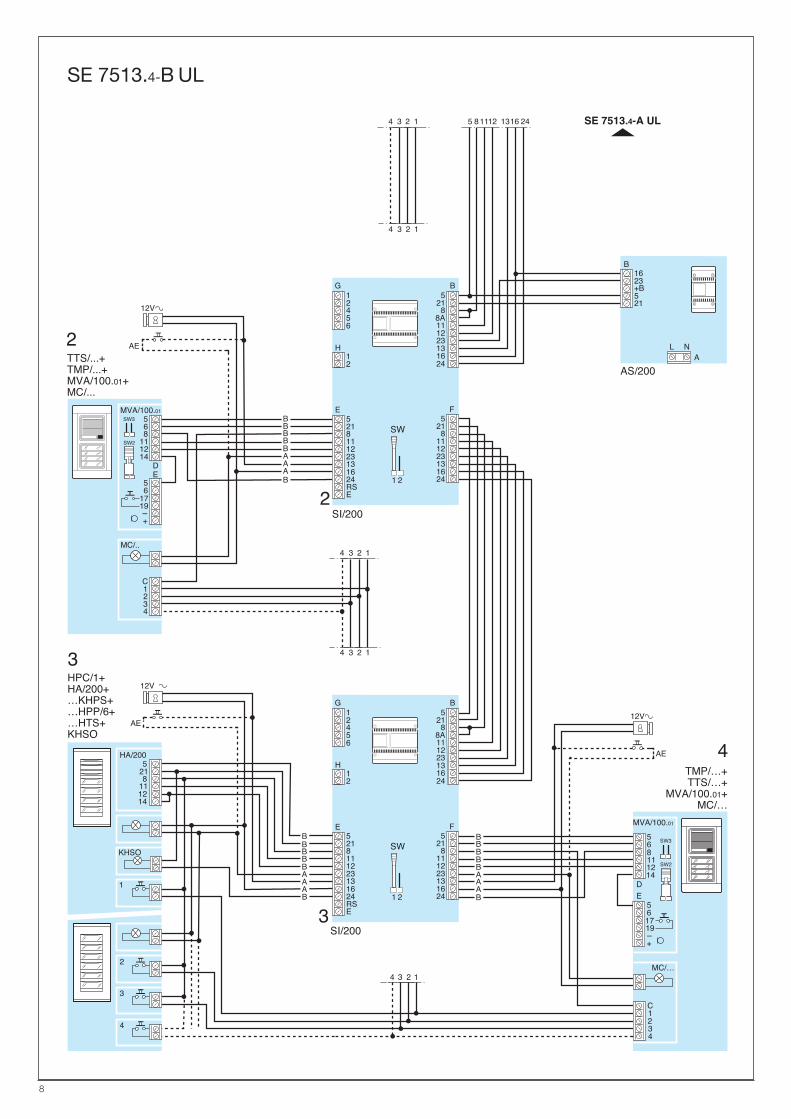
SE 7513.4 UL
SINGLE OR MULTI-FLAT INSTALLA-TION WITH 4 ENTRANCES.
EQUIPO MONO O MULTIFAMILIARCON 4 ENTRADAS.
SE 7513.4-A UL
4 3 2 1
4 3 2 1
E
SI/200
F
BG
H
521
88A111223131624
12456
12
3
E
SI/200
5218111223131624RSE
F
BG
H
521
8111223131624
521
88A111223131624
12456
12
AE
12V
BAAABBBBB
2
2
MVA/100.01
C1234
DE
MC/..
TTS/...+TMP/...+MVA/100.01+MC/...
B
AS/200A
115 128 1316 244 3 2 1
4 3 2 1
SE 7513.4-A UL
SW2
SW3
1 2
SW
1 2
SW
568
111214
56
1719-+
1623+B521
5681114
DE
12
MC/…
TMP/…+TTS/…+
MVA/100.01+MC/…
AE
12VAE
12V
34 2 1
AAABBBBB
BAAABBBBB
3
4
MVA/100.01
561719-+
C1234
SW2
SW3
HA/2005
218
2
3
111214
HPC/1+HA/200+…KHPS+…HPP/6+…HTS+KHSO
4
1B
KHSO
5218111223131624RSE
521
8111223131624
L N
8
SE 7513.4-B UL