BREAKERS DE CAJA ABIERTA · - CAPACIDAD DE RUPTURA: 100 KA (SEGÚN IEC 60947-2 CATEGORÍA “B”...
17
UAN25B3H- M2C2S261N UAN32B3H- M2C2S261P UAN40B3H- M2C2S261Q DISYUNTOR DE CAJA ABIERTA, TIPO UAN, DE 1250-2500 A - RANGO DE REGULACIÓN DE CORRRIENTE: 0,5 - 1 (1250 - 2,500 A) - TENSIÓN DE SERVICIO: 690 VAC - TENSION DE AISLAMIENTO: 1000 VAC - CAPACIDAD DE RUPTURA: 100 KA (SEGÚN IEC 60947-2 CATEGORÍA “B” KS C 4620). PARA 500/480/460 VAC Y 415/380/230/220 VAC - DIMENCIONES (FRAME "B", FIXED TYPE ): 408 x 404 x 296 mm DISYUNTOR DE CAJA ABIERTA, TIPO UAN, DE 1600-3200 A - RANGO DE REGULACIÓN DE CORRRIENTE: 0,5 - 1 (1600 - 3200 A) - TENSIÓN DE SERVICIO: 690 VAC - TENSION DE AISLAMIENTO: 1000 VAC - CAPACIDAD DE RUPTURA: 100 KA (SEGÚN IEC 60947-2 CATEGORÍA “B” KS C 4620). PARA 500/480/460 VAC Y 415/380/230/220 VAC - DIMENCIONES (FRAME "B", FIXED TYPE ): 408 x 404 x 296 mm DISYUNTOR DE CAJA ABIERTA, TIPO UAN, DE 2000-4000 A - RANGO DE REGULACIÓN DE CORRRIENTE: 0,5 - 1 (2000 - 4000 A) - TENSIÓN DE SERVICIO: 690 VAC - TENSION DE AISLAMIENTO: 1000 VAC - CAPACIDAD DE RUPTURA: 100 KA (SEGÚN IEC 60947-2 CATEGORÍA “B” KS C 4620) . PARA 500/480/460 VAC Y 415/380/230/220 VAC - DIMENCIONES (FRAME "B", FIXED TYPE ): 408 x 404 x 296 mm BREAKERS DE CAJA ABIERTA CÓDIGO DESCRIPCIÓN HYUNDAI 1
-
Upload
trinhthien -
Category
Documents
-
view
309 -
download
1
Transcript of BREAKERS DE CAJA ABIERTA · - CAPACIDAD DE RUPTURA: 100 KA (SEGÚN IEC 60947-2 CATEGORÍA “B”...

UAN25B3H-M2C2S261N
UAN32B3H-M2C2S261P
UAN40B3H-M2C2S261Q
DISYUNTOR DE CAJA ABIERTA, TIPO UAN, DE 1250-2500 A - RANGO DE REGULACIÓN DE CORRRIENTE: 0,5 - 1 (1250 - 2,500 A) - TENSIÓN DE SERVICIO: 690 VAC - TENSION DE AISLAMIENTO: 1000 VAC - CAPACIDAD DE RUPTURA: 100 KA (SEGÚN IEC 60947-2 CATEGORÍA “B” KS C 4620). PARA 500/480/460 VAC Y 415/380/230/220 VAC - DIMENCIONES (FRAME "B", FIXED TYPE ): 408 x 404 x 296 mmDISYUNTOR DE CAJA ABIERTA, TIPO UAN, DE 1600-3200 A - RANGO DE REGULACIÓN DE CORRRIENTE: 0,5 - 1 (1600 - 3200 A) - TENSIÓN DE SERVICIO: 690 VAC - TENSION DE AISLAMIENTO: 1000 VAC - CAPACIDAD DE RUPTURA: 100 KA (SEGÚN IEC 60947-2 CATEGORÍA “B” KS C 4620). PARA 500/480/460 VAC Y 415/380/230/220 VAC - DIMENCIONES (FRAME "B", FIXED TYPE ): 408 x 404 x 296 mm
DISYUNTOR DE CAJA ABIERTA, TIPO UAN, DE 2000-4000 A - RANGO DE REGULACIÓN DE CORRRIENTE: 0,5 - 1 (2000 - 4000 A) - TENSIÓN DE SERVICIO: 690 VAC - TENSION DE AISLAMIENTO: 1000 VAC - CAPACIDAD DE RUPTURA: 100 KA (SEGÚN IEC 60947-2 CATEGORÍA “B” KS C 4620) . PARA 500/480/460 VAC Y 415/380/230/220 VAC - DIMENCIONES (FRAME "B", FIXED TYPE ): 408 x 404 x 296 mm
BREAKERS DE CAJA ABIERTA
CÓDIGO DESCRIPCIÓN
HYUNDAI 1

U-Series
Air Circuit Breakers
LV & MV Circuit Breakers

/Air Circuit BreakersU-Series
4
Features
A frame[85kA]
B frame[100kA]
C frame[100kA]
D frame1)
[150kA]
•630 - 2,000A (UAN)•630 - 1,600A (UAS)
•630 - 4,000A (UAN)•2,000 - 3,200A (UAS)
•3,200 - 5,000A (UAN)
•4,000 - 6,300A (UAN)
368 mm328 mm
399 mm
624 mm
766 mm
460
mm
※ - Breaking capacity is at AC500V. 1) D frame will be available from 2015-1st half.
| Full line-up |
• U-Series ACB maximize your choice and satisfaction with compact size and dual (UAN/UAS) model.
Buildings
•Multipurpose buildings
•Hospitals
•Commercial buildings
•Hotels
Data centers & Networks
•Broadcasting stations
•IT/Telecommunications
Industrials
•Steel/Metal
•Gas/Chemical
•Pulp/Paper
Electric power facilities
•Electric power stations
• Electric power substations
•Dispersed power generators
•Renewable energy facilities
| Applications |
• U-Series ACB offering high breaking capacity and advanced protection trip relay is suitable to cover various applications including buildings, data centers, industrials and so on. U-Series ACB protects these facilities from harmonic frequency by 100 % capacity of N phase.

ACB
U-Series Air Circuit Breaker_5
| Compliance with standards |
Standard •IEC 60947-1,2 International Electrotechnical Commission
•EN 60947-2 European Standard
•GB China National Standard (Guojia Biaozhun)
•GOST R 50030.2-99 9 Government Standard of Russia
•GOST R 50030.1-2000 Government Standard of Russia
•KS C 4620 Korean Standards Association
Approval •ISO 18001, 14001, 9001
•KS/KOREA Korea Quality Certificate Standard Association
•CE Community European
•GOST-R/RUSSIA Government Standard of Russia
•CCC/CHINA China Compulsory Certification
•KR/KOREA Korean Register of Shipping
•GL/GERMANY Germanischer Lloyd
•LR/U.K Lloyd's Register of Shipping
•ABS/U.S.A American Bureau of Shipping
•BV/FRANCE Bureau Veritas
•NK/JAPAN Nippon Kaiji Kyokai
•DNV/NORWAY Det Norske Veritas
•RINA/ITALY Regisero Italland Navale
•RS/RUSSIA Russian Maritime Register of Shipping
CB type test •DEKRA Formerly KEMA Quality Registered
•KERI Korea Electrotechnology Research Institute

/Air Circuit BreakersU-Series
6
Features
❶ Motor❷ Closing coil❸ Trip coil ❹ Double trip coil❺ Trip supervision coil❻ Under voltage trip coil
❼ Auxiliary switch❽ Condenser trip device❾ Lifting lug❿ Mechanical interlock kit Phase insulation barrier ON/OFF button cover
OCR portable checker Key lock device Miss-insertion preventer Fixing block Counter OCR & Alarm switch reset device
❶ ❷ ❸ ❹
❺ ❻ ❼ ❽
❾ ❿
| Various accessories |
Test jumper Draw-in/out handle Draw-in/out and
position lock device Door flange Dust cover
[ Body ]

/Air Circuit BreakersU-Series
10
Vertical/Horizontal
Horizontal/Front
Horizontal/Vertical
Front/Vertical
Vertical/Front
Front/Horizontal
| Multiple terminal busbar connections |
•Increases the user's convenience by diversified terminal connection methods according to busbar's type. •Simply turn a horizontal connector in 90̊ to make it a vertical connector (The opposite case is the same).
Mixed connection (Top/Bottom)
Standard connection
Vertical Horizontal Front
※ - Changing connector is available only for UAN/UAS A frame 630 - 1,600A, UAN/UAS B frame 2,000 - 3,200A. - Front connection type is suitable for panels with limited installation space. - When changing connections above 4,000A, additional component is needed. Please contact us.
Features
ACB
U-Series Air Circuit Breaker_11
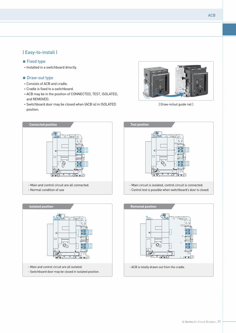
[ Draw-in/out guide rail ]
- Main and control circuit are all connected.- Normal condition of use
Test position
- Main circuit is isolated, control circuit is connected.- Control test is possible when switchboard’s door is closed.
Isolated position
- Main and control circuit are all isolated.- Switchboard door may be closed in isolated position.
Removed position
- ACB is totally drawn out from the cradle.
Connected position
접접접접(Connected Position)
| Easy-to-install |
Fixed type •Installed in a switchboard directly.
Draw-out type •Consists of ACB and cradle. •Cradle is fixed to a switchboard. • ACB may be in the position of CONNECTED, TEST, ISOLATED,
and REMOVED. • Switchboard door may be closed when (ACB is) in ISOLATED
position.

/Air Circuit BreakersU-Series
12
| Internals |
❶ Arc chamber ❷ Frame❸ Counter ❹ Auxiliary switch❺ Motor❻ Closing/Trip/UVT coil
❼ MHT device❽ Protection trip relay (OCR)❾ Mechanism❿ Draw-in/out device Front cover Control terminal protection cover
Control terminal Manual charging handle Closing spring Moving contact Fixed contact Terminal busbar
❶
❷❸
❹
❺
❻
❾
❿
❻
❹
❽
❾
❿
❼
❽
❶
Current transformer Terminal clip Cradle
Structure

ACB
U-Series Air Circuit Breaker_13
| Externals |
[ Inside ] [ Rear ]
[ Fixed type ] [ Draw-out type ]
❸
❹
❻❼
❽❾
❿
❺
❶
❷
❸
❹
❻
❺
❶
❷
[ Front ]
[ Cradle ]
❶ Control terminal❷ Front cover❸ Close/Open indicator❹ Close button❺ Protection trip relay (OCR)❻ Open button
❼ Position lock device❽ Position lock release button❾ Draw-in/out handle insertion hole❿ Position indicator Counter Charged/Discharged indicator
Manual charging handle Name plate Arc shield Terminal busbar OCR & Alarm switch reset button Draw-in/out guide rail

/Air Circuit BreakersU-Series
14
Frame A frame B frame C frame D frame1) A frame B frame
Model UAN UAS
Recognition order code:Rated current (In max at 40 C̊) (A)
06 : 63008 : 80010 : 1,00012 : 1,25016 : 1,60020 : 2,000
06 : 63008 : 80010 : 1,00012 : 1,25016 : 1,60020 : 2,00025 : 2,50032 : 3,20040 : 4,000
32 : 3,20040 : 4,00050 : 5,000
40 : 4,00050 : 5,00063 : 6,300
06 : 63008 : 80010 : 1,00012 : 1,25016 : 1,600
20 : 2,00025 : 2,50032 : 3,200
Rated operating voltage (Ue) (V) AC690 AC690Rated insulation voltage (Ui) (V) AC1,000 AC1,000Frequency (Hz) 50/60 50/60Number of poles 3, 4 3, 4Current setting range (….. x In max) 0.4 - 1.0 0.4 - 1.0Rated current of neutral pole (…..% x In) 100 % 100 %
Rated breaking capacity(Icu) (kA sym)
IEC 60947-2category “B”
KS C 4620
AC690/600/550V 65 85 85 100 55 70AC500/480/460V 85 100 100 150 65 85AC415/380/230/220V 85 100 100 150 65 85
Rated service breaking capacity (…..% x Icu) 100 % 100 %
Rated making capacity(Icm)(kA peak)
IEC 60947-2category “B”
KS C 4620
AC690/600/550V 143 187 187 220 121 154AC500/480/460V 187 220 220 330 143 187AC415/380/230/220V 187 220 220 330 143 187
Rated short-time capacity(Icw)(kA, without Inst.)
1 sec 65 85 85 100 55 702 sec 60 75 75 100 45 653 sec 50 65 65 100 36 55
Rated impulse withstand voltage (Uimp) (kV) 12 12Maximum total breaking time (ms) 40 40
Closing operating timeMotor charging time (sec) max. 10 10
Closing time (ms) max. 80 80
Life cycle (times)
MechanicalWithout maintenance 20,000 15,000 10,000 10,000 20,000 15,000
With maintenance 30,000 2,000 2,000 15,000 30,000 20,000
ElectricalWithout maintenance 5,000 06 - 20 : 10,000
25 - 40 : 5,000 2,000 2,000 5,000 5,000
With maintenance 10,000 06 - 20 : 15,00025 - 40 : 10,000 5,000 5,000 10,000 10,000
Weight (kg)
3 poleDraw-out type 63 06 - 32 : 87
40 : 107 145 210 63 87
Fixed type 34 06 - 32 : 4440 : 61 76 120 34 44
4 poleDraw-out type 280 06 - 32 : 130
40 : 61 173 280 74 103
Fixed type 44 06 - 32 : 5540 : 81 81 160 44 55
External dimension (mm)(WxHxD, except busbar)
3 poleDraw-out type 328 x 460 x 368 399 x 460 x 368 624 x 460 x 368 766×460×368.4 328 x 460 x 368 399 x 460 x 368
Fixed type 337 x 404 x 296 408 x 404 x 296 633 x 404 x 296 775.4×404.4×295.8 337 x 404 x 296 408 x 404 x 296
4 poleDraw-out type 413 x 460 x 368 514 x 460 x 368 794 x 460 x 368 996×460×368.4 413 x 460 x 368 514 x 460 x 368
Fixed type 422 x 404 x 296 523 x 404 x 296 803 x 404 x 296 1,005×404.4×295.8 422 x 404 x 296 523 x 404 x 296
D D
H
W
H
WD D
H
W
H
W
Ratings
※ 1) D frame will be available from 2015-1st half.
Fixed type Draw-out type

ACB
U-Series Air Circuit Breaker_29
ACB Terminal
VR VS VT VN
UPR
ACB Terminal
VR VS VT VN
UPR
VNVTVSVR
VNVTVSVR
A B C
A B C N
75
4256.4
91.4
46.6
27.629.1
3 CT 3 WireVoltage connection
3 P 3 Wire
4 P 4 Wire / 3 P 4 Wire
| Measurement |
Outside view
Voltage module•UPR-LP/LH/SP trip relay offers VM (voltage module) as an essential option, to measure voltage.•Voltage input range: AC69 - 690V
Connect with ACB terminal
Connect busbar
UAN※ Install the length of connecting cable between ACB and voltage module is less than 50mm.

/Air Circuit BreakersU-Series
30
ACB 1
In
Out
ACB 2-1
In
Out
In
Out
In In
Out Out
ACB 2-2
Fault A
Fault B
ACB 3-1 ACB 3-2 ACB 3-N
Zone 1
Zone 2
Zone 3
ZSI connecting
In case of that short time-delay or ground fault accident occurs at ZSI built in system, the breaker at accident site sends ZSI signal to halt upstream breaker’s operation.
To eliminate a breakdown, trip relay of ACB at accident site activates trip operation without time delay.
The upstream breaker that received ZSI signal adhere to pre-set short time-delay or ground fault time delay for protective coordination in the system. However upstream breaker that did not receive its signal will trip instantaneously.
For ordinary ZSI operation, it should arrange operation time accordingly so that downstream circuit breakers will react before upstream ones under overcurrent/short time delay/ground fault situations.
ZSI connecting line needs to be maximum 3m.
Example
| Zone selective interlock function |
Zone selective interlocking drops delay time that eliminates faults for breakers.It minimizes the shock that all kinds of electric machineries get under fault conditions.
※ It is not available in self-power OCR.
Protection Trip Relay (OCR)

ACB
U-Series Air Circuit Breaker_31
| Communication function |
Modbus-RTU / RS-485•Operation mode: Differential•Distance: Max.1.2km•Cable: RS-485 shielded twist 2-pair cable•Baud rate: 9,600, 19,200, 38,400 bps•Transmission method: Half-duplex•Termination: 150 Ω
Measurementpart
Self power
SMPSpower
R S T N
Rogowski CT
Display(LCD, LED)
Trip operationRelay
selection
MHT
ACB trip
PTA contact
LTD contact
STD/INST contact
GFT or ELT contact
COMMON contact
MCU processing
External contact
ZSI
ZSI output +ZSI output -ZSI input +ZSI input -
COMM.RS-485 +
RS-485 -
Power CT
ZCT Earth leakage
Testterminal
ACB
Trip relay
110V - 220V
SCADA system
Modbus/RS-485
| System diagram |

/Air Circuit BreakersU-Series
32
NCTk ℓ
NT
CT1CT2
CT3
Ac
22
L
21
NTSR
Rn Sn Tn Nn MCR+
MCR-
3029
PT
MHT
TTNN
TP
Rn Sn Tn
R S T
1a forMCR
NCT NCT1 2
N
Nn
CT4
Over-currentprotective device
UPR-LN
UPR-LN
NT
CT1CT2
CT3
S/I
24
Ac
22
L
21
NTSR
Rn Sn Tn Nn
23
P/T
COM MCR+
MCR-
3029
35
19
2S
0SPT
20
MHTMHT
TTNN
TTPP
Rn Sn Tn
ZSI
G/E
26
R S T
1a for MCR
NCT NCT1 2
ZI1
ZI2
ZO1
ZO2
31 32 33 34
+ - + -IN OUT
COM
36
+ -COMMU-NICA-TION
+ -
N
Nn
CT4RR+ RR-
5 6
+ -REMOTERESET
Over-currentprotective device
UPR-LA
20S
Source
AC,DC100-250V - S
NCTk ℓ
UPR-LA
| Circuit diagrams |
Protection Trip Relay (OCR)

ACB
U-Series Air Circuit Breaker_33
20S
Source
AC,DC100-250V - S
NCTk ℓk ℓ
NT
CT1CT2
CT3
S/I
24
Ac
22
L
21
NTSR
Rn Sn Tn Nn
23 27
P/T ELT
COM
302928
35
19
2S
0SPT
20
MHTMHT
TTNN
TP
Rn Sn Tn
ZSI
G/E
26
R S T
1a for MCR
ELT1 2
NCT NCT1 2
ZI1
ZI2
ZO1
ZO2
31 32 33 34
+ - + -IN OUT
COM
36
+ -COMMU-NICA-TION
+ -
N
Nn
CT4RR+ RR-
5 6
+ -REMOTERESET
MCR+
MCR-
UPR-LAG / LAZ
Over-currentprotective device
UPR-LAG/LAZ
20S
Source
AC,DC100-250V - S
NTCOM 0SPT
MHTMHT
TTNN
TP
COM RR+ RR- MCR+
MCR-
CT1CT2
CT3
S/I
24
Ac
22
L
21
NTSR
Rn Sn Tn Nn
23
P/T
3029
35
19
2S
20Rn Sn Tn
ZSI
G/E
26
R S T
1a for MCR
NCT NCT1 2
ZI1
ZI2
ZO1
ZO2
31 32 33 34
+ - + -IN OUT
36
+ -COMMU-NICA-TION
+ -
N
Nn
CT4
5 6
+ -REMOTERESET
VM
VR VNVTVS
VR VNVTVS
3Ø3W/3Ø4W
UPR-LP / LH
NCTk ℓ
Over-currentprotective device
UPR-LP/LH

/Air Circuit BreakersU-Series
34
NTMCR+
MCR- PT
MHT
TTNN
TP
1a forMCR
CT1CT2
CT3
Ac
22
L
21
NTSR
Rn Sn Tn Nn
Rn Sn Tn
R S T
UPR-SN
Over-currentprotective device
UPR-SN
NTCOM MCR+
MCR- 0SPT
MHT
TTNN
TTPP
1a for MCR
ZI1
ZI2
ZO1
ZO2 COM RR+ RR-
20S
Source
AC,DC100-250V - S
CT1CT2
CT3
S/I
24
Ac
22
L
21
NTSR
Rn Sn Tn Nn
23
P/T
35
19
2S
20Rn Sn Tn
ZSI
G/E
26
R S T
31 32 33 34
+ - + -IN OUT
36
+ -COMMU-NICA-TION
+ -
5 6
+ -REMOTERESET
UPR-SA
Over-currentprotective device
UPR-SA
| Circuit diagrams |
Protection Trip Relay (OCR)

ACB
U-Series Air Circuit Breaker_35
20S
Source
AC,DC100-250V - S
3Ø3W/3Ø4W
CT1CT2
CT3
2422
L
21
NTSR
23
P/T
35
19
2S
20Rn Sn Tn
ZSI
26
R S T
31 32 33 34
+ - + -IN OUT
36
+ -COMMU-NICA-TION
+ -
5 6
+ -REMOTERESET
VM
VR VTVS
VR VTVS
UPR-SP
NTCOM 0SPT
MHTMHT
TTNN
TP
COM RR+ RR- MCR+
MCR-S/IAcRn Sn Tn Nn G/E
1a for MCR
ZI1
ZI2
ZO1
ZO2
Over-currentprotective device
UPR-SP