Bousias, S. , Sextos, A., Kwon, O-S., Taskari, O ...
29
Bousias, S., Sextos, A., Kwon, O-S., Taskari, O., Elnashai, A. S., Evaggeliou, N., & Di Sarno, L. (2017). Intercontinental Hybrid Simulation for the Assessment of a Three-Span R/C Highway Overpass. Journal of Earthquake Engineering. https://doi.org/10.1080/13632469.2017.1351406 Peer reviewed version License (if available): Unspecified Link to published version (if available): 10.1080/13632469.2017.1351406 Link to publication record in Explore Bristol Research PDF-document This is the author accepted manuscript (AAM). The final published version (version of record) is available online via Taylor & Francis at http://www.tandfonline.com/doi/full/10.1080/13632469.2017.1351406. Please refer to any applicable terms of use of the publisher. University of Bristol - Explore Bristol Research General rights This document is made available in accordance with publisher policies. Please cite only the published version using the reference above. Full terms of use are available: http://www.bristol.ac.uk/red/research-policy/pure/user-guides/ebr-terms/
Transcript of Bousias, S. , Sextos, A., Kwon, O-S., Taskari, O ...

Bousias, S., Sextos, A., Kwon, O-S., Taskari, O., Elnashai, A. S.,Evaggeliou, N., & Di Sarno, L. (2017). Intercontinental HybridSimulation for the Assessment of a Three-Span R/C HighwayOverpass. Journal of Earthquake Engineering.https://doi.org/10.1080/13632469.2017.1351406
Peer reviewed versionLicense (if available):UnspecifiedLink to published version (if available):10.1080/13632469.2017.1351406
Link to publication record in Explore Bristol ResearchPDF-document
This is the author accepted manuscript (AAM). The final published version (version of record) is available onlinevia Taylor & Francis at http://www.tandfonline.com/doi/full/10.1080/13632469.2017.1351406. Please refer to anyapplicable terms of use of the publisher.
University of Bristol - Explore Bristol ResearchGeneral rights
This document is made available in accordance with publisher policies. Please cite only thepublished version using the reference above. Full terms of use are available:http://www.bristol.ac.uk/red/research-policy/pure/user-guides/ebr-terms/
1
Intercontinental Hybrid Simulation for the Assessment of
a three-span R/C Highway Overpass
Stathis Bousias1, Anastasios Sextos2, Oh-Sung Kwon3, Olympia Taskari4
Amr Elnashai5, Nikos Evangeliou6 and Luigi Di Sarno7
ABSTRACT
This paper presents hybrid simulations of a three-span R/C bridge among E.U., U.S. and
Canada. The tests involved partners located on both sides of the Atlantic with each one
assigned a numerical or a physical module of the sub-structured bridge. Despite the network
latency in linking five remote sites located on the two sides of the Atlantic (compared to
previous studies in which sites were not as widely distributed) and considering the rate-
dependency of the physical specimen as per Molina et al. (2002), the intercontinental hybrid
simulation was accomplished and repeated successfully employing different tools, thus
highlighting the robustness, efficiency and repetitiveness of the approach. Adaptations,
challenges and limitations are critically discussed particularly focusing on the implications of
network communication latency, the insensitivity of the sub-structuring arrangement and the
accuracy of the results obtained.
1. INTRODUCTION
Hybrid simulation is a cost-effective alternative, compared to large scale shake table tests
for dynamic testing of structural systems, combining physical testing with numerical
simulation. In hybrid simulation, the structure is partitioned into a number of components; the
unknown behavior of the most complex component is experimentally tested in the laboratory
while the remainder of the emulated system is numerically analyzed in computer stations.
The numerical to physical coupling is achieved via a transfer system comprising of a test
frame, actuators, sensors, a controller, and an interface program which links a controller to
the numerical model.
1 Professor, Dept. of Civil Engineering, University of Patras, Greece 2 Associate Professor, Dept. of Civil Engineering, University of Bristol, UK & Aristotle University of Thessaloniki, Greece 3 Associate Professor, Dept. of Civil Engineering, University of Toronto, Canada 4 Dr. Civil Engineer, Dept. of Civil Engineering, Aristotle University of Thessaloniki, Greece 5 Dean of Engineering, Pennsylvania State University, US 6 Post-doc researcher, Dept. of Electrical and Computer Engineering, University of Patras, Greece 7 Assistant Professor, Dept. of Engineering, University of Sannio, Italy

2
The same sub-structuring concept has also been successfully applied for the coordination
of purely numerical analysis modules where no physical testing is performed, in contrast to
the hybrid simulation application. This, so called, “multi-platform simulation” permits the
appropriate selection and combination of different numerical analysis packages, thus enabling
the concurrent use of the most sophisticated constitutive laws, element types and features of
each package for each corresponding part of the system (i.e. abutments, superstructure and
supporting pile groups for instance in the case of a long bridge), depending on the foreseen
inelastic material behavior, level and nature of the seismic forces, boundary conditions and
the geometry of the particular problem. As for the case of hybrid testing though, the
computational cost and level of expertise is relatively high compared to a conventional all-
inclusive simulation package. In addition, its computational efficiency is network-dependent.
The communication among the numerical and experimental components as well as the
solution of the equation of motion of the entire structure is achieved via purpose-specific
coordination software. To this end, specialized software platforms have been developed, e.g.
OpenFresco (Schellenberg et al. 2009) and UI-SimCor (Kwon et al. 2008)]. In the former, the
analysis of the numerical substructures is performed within a finite element software
(OpenSees) and the only network communication required is that with the laboratory-tested
component(s). This feature is particularly advantageous for the hybrid simulation of
structures with large number of DOFs, as it keeps network communication to the minimum.
On the other hand, UI-SimCor relies on external finite element codes and physical testing for
the numerical and the experimental substructures, respectively, while solving a numerical
time integration scheme and fully undertaking the task of communicating the deformation
vector to all substructures thus receiving the returning measured deformation/resistance
vectors. The intense network communication is particularly problematic for structures with
many substructures and/or degrees-of-freedom and may even lead to process halting.
In general, most of the hybrid simulation tests have been conducted locally, where both
numerical analysis and physical experimentation have been conducted within a single
laboratory. However, the nature of the test lends itself to allowing substructures to be
geographically-distributed between test sites across a computer network. In this context, there
is no need for either using a unique experimental facility or for satisfying physical proximity
for the multiple experimental or numerical components. The components (analytical,
experimental or a combination of both) are treated on different networked computers and, can
thus be located anywhere in the world. This multi-site approach has already been developed
in the United States for the assessment of complex interacting systems. It was supported by

3
National Science Foundation, through the Network for Earthquake Engineering Simulation
(NEES, www.nees.org) scheme (Kwon et al. 2005; Pan et al. 2005; Saouma et al. 2012;
Spencer et al. 2004; Takahashi and Fenves 2006; among many others) with the aim to raise
the limitations related to the laboratory capacities. Spencer et al. (2004), for instance, tested a
two-bay single-story steel frame at an expanded time scale known as the Multi-Site Online
Simulation Testbed (MOST) experiment. This experiment coupled two large-scale physical
components in Illinois and Colorado with a computational simulation. Building on the MOST
experiment, the so-called Fast-MOST test (Mosqueda 2006; Mosqueda and Stojadinović
2008) and the Multi-site soil-structure-foundation interaction test, MISST, (Elnashai et al.
2008; Spencer et al. 2006) were then conducted. The first (Fast-MOST) consisted of a six-
span bridge with five remote experimental and numerical column substructures distributed
within NEES facilities: namely, UC Berkeley, University of Colorado, Boulder, SUNY
Buffalo, University of Illinois at Urbana-Champaign (UIUC) and Lehigh University while the
latter (MISST) simulated the response of a bridge structure which was partitioned into five
separate modules distributed at three of NEES equipment sites (UIUC, Lehigh University,
and Rensselaer Polytechnic Institute). Similarly, a grid-based network of advanced
laboratories for earthquake engineering simulation has been developed in Europe (UK-
NEES), initially comprising the research laboratories at the Universities of Bristol, Oxford
and Cambridge (Ojaghi et al. 2010).
Based on the examined problem and the available equipment, pseudo-dynamic hybrid
tests can be executed in real time or in an extended time scale. When the rate-dependent
behavior of an experimental component is of interest, as is for instance the case of rubber
bearings or viscous dampers, the strain-rate dependency of the restoring forces yields the
execution of the test in an extended time scale not reliable. In this case, hybrid testing must
be conducted in real time (Carrion et al. 2009; Chae et al. 2014; Chen et al. 2014; Nakashima
and Masaoka 1999) or at an affordable speed for the available equipment accompanied by
proper compensation techniques for the restoring forces of the experimentally tested
components. In this light, Molina et al. (2002) proposed a simple proportional correction of
the measured forces that compensates the remaining strain-rate effect of rubber bearings due
to the unrealistically slow speed of the test; the correction factor being obtained by means of
a characterizing test on the specific rubber isolators, which were of interest in the particular
test. Several other Real Time Distributed Hybrid Tests (RTHT) have been carried out
highlighting the challenges and current limitations for studying the rate-dependent dynamic

4
coupling (Chen and Ricles 2009; Dion et al. 2010; Ojaghi et al. 2014; Schellenberg et al.
2014).
In case that rate-dependent problems studied by means of remote sites that are
geographically distributed at a great distance, the inevitable additional time delay in
communication introduces a considerable degree of uncertainty, which is further hindered by
the lack of a systematic study for the exploration of possible network implications. This is
further amplified by the fact that, despite the increasing number of geographically distributed
tests within US or Europe, the number of wide range international hybrid tests is rather
limited. Takahashi et al. (2008) performed a geographically distributed test for a two-span
continuous bridge between UC Berkeley and Kyoto University in Japan. The strong nonlinear
behavior of the C-bent RC and the steel pier of the bridge were experimentally tested at the
two laboratories, leading to a very stable set of tests involving strongly nonlinear behavior.
More recently, a continuous intercontinental test was conducted between University of Kassel
in Germany and UC Berkeley in the US (http://openfresco.berkeley.edu/2012/09/kassel-
berkeley/). The experimental substructure of the test consisted of a friction device (Dorka
1995) and a fixed Tuned-Mass-Damper (TMD). The computational portion of the hybrid
model consisted of a single degree of freedom mass with viscous damping. Computations
were executed at UC Berkeley and the experimental substructure was located at the
University of Kassel. Due to the average network communication time of 0.2 sec between the
two sites and the uncertainty in the network lag, the 0.01 sec of numerical integration time
was executed in 1 sec of real-time, which resulted in the time scale factor of 100.
Along these lines, the objectives of this paper are to:
systematically study the effect of remote host distance on the feasibility of executing
hybrid simulation at the system level among long-separated sites
investigate the feasibility of implementing hybrid simulation tools and procedures that
are not tailored to the existing equipment in Europe, and
demonstrate the stability and accuracy of an intercontinental multi-platform and/or
hybrid test for the case of a real bridge with rate-dependent behavior concentrated on
its elastomeric bearings while considering soil-embankment-abutment-bridge
interaction (Taskari and Sextos 2015).
The bridge studied was partitioned into five structural components (modules), each one
being analyzed using specific software in different computer stations (Figure 1) located at
Aristotle University of Thessaloniki, Greece (AUTH), University of Patras, Greece
(UPATRAS), University of Sannio, Italy (USANNIO), University of Illinois at Urbana-

5
Champaign, U.S. (UIUC) and University of Toronto, Canada (UofT). At the final stage, the
numerical module representing the left bridge bearing was replaced by a physical specimen
tested at the Structures laboratory at University of Patras. In both cases (i.e. multi-platform
simulation and hybrid testing) UI-SimCor (Kwon et al. 2007, 2008) was used as the
simulation coordinator. The description of the series of the experiments, from the
geographically-distributed multi-platform simulation to the intercontinental hybrid
simulation, as well as the limitations, challenges met and adaptations required towards a
robust, intercontinental hybrid testing are discussed in the following.
Figure 1. Geographical distribution of the numerical and experimental sub-structures involved in the intercontinental multi-platform simulation and hybrid testing. All sites
connect to the coordinator located at AUTH.
2. DESCRIPTION OF THE BRIDGE
The particular structure is a three-span (27-45-27m) reinforced concrete (R/C) overpass of
a total length of 99.0 m, which is part of EGNATIA highway in Northern Greece. The slope
of the deck along its axis is constant and equal to 7% with increasing altitudes towards the
west abutment. The deck is a 10 m wide, prestressed concrete box girder section, while the
two piers are designed with a solid circular reinforced concrete section with diameter equal to
2.0 m and are monolithically connected to the deck. The heights of the left and the right pier
are 7.95 m and 9.35 m, respectively. Two series of 48 longitudinal bars of 25 mm diameter
are spaced equally around the section perimeter, while the transverse reinforcement consists
of an outer spiral of 14 mm diameter spaced at 75 mm and an inner 16 mm spiral equally
spaced. The deck is supported on two elastomeric bearings (350 ×450 ×136mm) with a shear
modulus (G) equal to 1.0 MPa, which is supported on seat type abutments with a backwall
height equal to 2.0 m. Sliding joints of 10 cm and 15 cm length separate the deck from the
abutment along the longitudinal and the transverse direction, respectively. Given the stiff soil
formations corresponding to class B according to EC8-Part 2 (CEN 2005) or C according to

6
NEHRP [FEMA440, 2004], surface footings of 9 m × 8 m × 2 m and 12 m × 4.5 m × 1.5 m
are designed for the foundation of the piers and the abutments, respectively. A general layout
of the bridge configuration is illustrated in Figure 2. The bridge was designed for a peak
ground acceleration of 0.16 g adopting an importance factor equal to 1.0, and a behavior (or
force reduction) factor equal to 2.40 according to Greek Seismic Code (Earthquake Planning
and Protection Organization (EPPO) 2000; Ministry of Public Works of Greece 1999) that
was used at the time of construction.
Figure 2. General overview of the bridge configuration.
3. IMPLEMENTATION AND VERIFICATION OF HYBRID TESTING
3.1 System sub-structuring
For the purpose of this study, the five components (modules), were picked to correspond
to the bridge deck, the left pier, the right pier, as well as the left and right abutment bearing.
Each component was numerically analyzed or experimentally tested as described in the
following section. Figure 3 illustrates the bridge sub-structuring scheme used for the multi-
platform simulation and the hybrid testing.
The specialized software platform UI-SimCor (Kwon et al. 2008) developed by the
research group of the University of Illinois was used for coordinating the simulation. UI-
SimCor involves an enhanced MATLAB-based script which coordinates software or
hardware components through TCP-IP connections. Analytical models of some parts of the
structure or experimental specimens representing specific parts of the same structure are all
considered as super-elements with many DOFs. Specially developed interface programs
permit the interaction with different analysis software such as Zeus-NL (Elnashai et al. 2002)
OpenSees (McKenna et al. 2002), FedeasLab (Filippou and Constantinides 2004), and
Abaqus (Hibbit and Sorenson 2006). After the initialization step where the network
connection between the modules is established, the stiffness matrix of the entire structure is
evaluated using predefined deformation values. The gravity forces are applied during the
static loading stage where displacements due to gravity forces are imposed. Finally, UI-

7
SimCor performs Newmark numerical integration as it steps through the seismic record by
utilizing the operator-splitting (OS) method with a modified α- parameter (a-OS method),
which introduces numerical damping to suppress the high-frequency spurious oscillations.
Figure 3. Layout of the bridge sub-structuring for the multi-platform
simulation and hybrid testing.
3.2 Experimental substructure module
The physical module comprised the elastomeric bearings located at the left end of the
bridge. The experimental setup installed at the Structures Laboratory of the University of
Patras employed a pair of bearings placed one on top of the other (back-to-back configuration)
and inserted between stiff end plates – the latter were prevented from displacing or rotating
(Figure 4). A nearly constant vertical load of 240 kN was imposed to the isolators, regardless
of the level of applied lateral deformation. The 350 mm-in-diameter low damping rubber
bearings used (ALGA, Type NB4) consisted of seven, 11 mm-thick layers of rubber and six
steel plates each of a thickness of 6 mm. The total height of each bearing, including the
external connection plates, was 181 mm, while the total rubber height was 77 mm. The
prescribed shear modulus of the rubber was 0.99 MPa. The measured horizontal and vertical
stiffness of the bearings were estimated as: Kh = 1237 kN/m and Kv = 469.6 MN/m.
Although a dynamic actuator (with a 1500 l/min servo valve supplied by a 600 l/min
pump) was employed for applying command displacement increments, during the tests
presented here the command displacement were applied in a slow (relatively to actual seismic
8
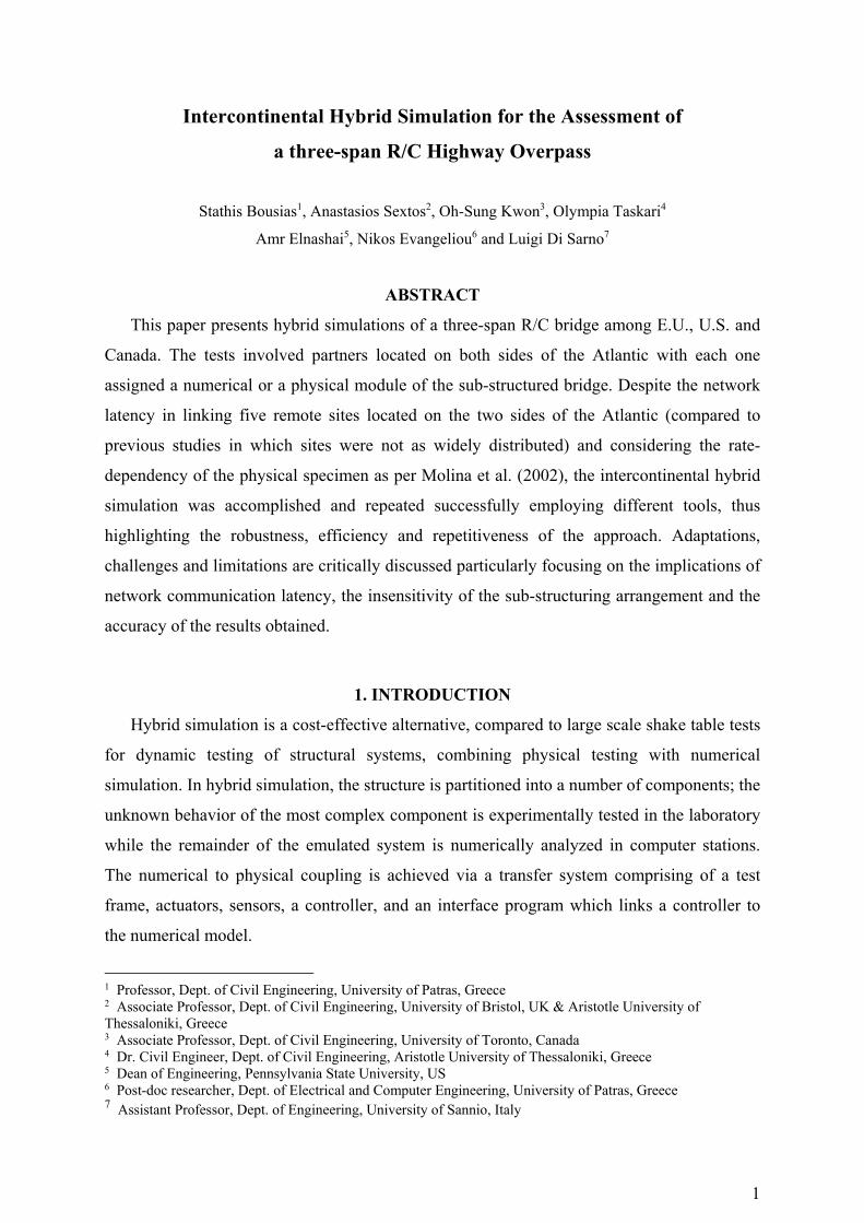
velocity), step-wise manner. Owing to the quasi-static nature of the test, strain rate effects
affecting the response of the elastomeric bearing cannot be accounted for by applying
realistic strain rate. Thus, the force correction procedure proposed by Molina et al. (2002)
was adopted to approximately account for the increase in force due to the strain rate effect;
the measured force was adjusted as a function of measured quantities (force, displacement,
force rate and displacement rate) to yield a rate-dependent force estimate. Such calibration
was realized by subjecting a pair of identical isolators (different to those used in the final test,
to avoid any effect of scragging) to different testing velocities and for deformation levels
similar to those expected during the hybrid tests. From these tests it was possible to obtain a
relationship for the “corrected” force based on other measured quantities. The corrected force
was then returned to the numerical integration scheme for advancing the solution to the next
step.
Figure 4. Experimental setup (top) and bearings tested (bottom, left) at the University of Patras along with the computational server at the University of Thessaloniki
(bottom, right).
3.3 Numerical substructure modules
OpenSees analysis platform was used for the numerical analysis of all the numerical
modules. Each module was modeled separately with the following assumptions:
9
Module 1. Bridge deck: The deck is expected to remain linear and thus was modeled with
elastic beam-column elements.
Modules 2 and 3: Left and Right Pier: The left pier was modeled with nonlinear beam-
column fiber elements. The stress-strain relationships for the confined and the unconfined
concrete were obtained from the literature (Mander et al. 1988), while the uniaxial Giuffré-
Menegotto-Pinto (Taucer et al. 1991) material with isotropic strain hardening was used for
the reinforcement bars. The median design strength of concrete and the yielding strength of
reinforcing steel are 35.7 and 550 MPa, respectively. Soil-structure interaction was
considered at the pier footing. The dynamic impedance at the footing-soil interface was
derived according to Mylonakis et al.(2006), as a product of the static stiffness K, times the
dynamic stiffness coefficient k(ω) where ω is the frequency of interest. In this case, ω was
assumed to be equal to the first natural cyclic frequency of the examined bridge. The
radiation damping coefficient C(ω) was then derived for the same cyclic frequency. The
derived values for the dynamic stiffness and dashpot coefficients are presented in Figure 5.
Modules 4 and 5: Left and Right Bearings: The hysteretic behavior of the bearings is
considered with the use of nonlinear translational springs, with a horizontal effective stiffness
determined by the shear modulus of the elastomer (G), the full cross-sectional area (A) and
the total thickness of the rubber layers (tr), i.e. Keff =GA/tr. The yield force (Fy) and
displacement (Dy) of the bearing was determined assuming a value for the maximum shear
strain equal to 2.0 and a value of 2.0 for the elastic (K1) over the inelastic stiffness (K2) ratio
(Naeim and Kelly 1999).

10
Figure 5. Overview of the numerical model employed for the purposes of multi-platform simulation. Sub-structuring is identical to that of Fig. 3, however, all modules are purely
numerical.
3.4 Analysis coordinator
UI-SimCor acted as the Analysis Coordinator. Each module was analyzed in a different
computer station after appropriate definition of the control points at the joint dynamic degrees
of freedom (DOFs) of interest. At each analysis step, a predefined displacement was imposed
by the analysis coordinator and forces were measured to each specific module to establish the
initial stiffness matrix of the sub-structured system. The established matrix was then used in
the static and dynamic loading stage to determine the desirable target displacements. An
indicative plot of seismic response of the individual bridge components under the N-S
component of the ground motion (PGA: 0.32g) recorded at a site in El Centro, California,
during the Imperial Valley earthquake of May 18, 1940, is depicted in Figure 6. Given that
the intensity of the particular earthquake record exceeded the design level, strongly nonlinear
response was observed in all piers and bearings.
3.5 Verification of hybrid simulation
Before proceeding with the hybrid simulation, it was deemed necessary to ensure that the
multi-platform analysis yields similar results to that of the full model (i.e., the single module
finite element model running on a single computer).

11
Figure 6. Seismic response of individual bridge components (piers, bearings, deck) under the El Centro earthquake.
12
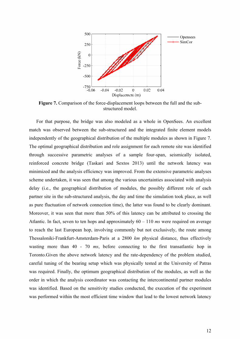
Figure 7. Comparison of the force-displacement loops between the full and the sub-structured model.
For that purpose, the bridge was also modeled as a whole in OpenSees. An excellent
match was observed between the sub-structured and the integrated finite element models
independently of the geographical distribution of the multiple modules as shown in Figure 7.
The optimal geographical distribution and role assignment for each remote site was identified
through successive parametric analyses of a sample four-span, seismically isolated,
reinforced concrete bridge (Taskari and Sextos 2013) until the network latency was
minimized and the analysis efficiency was improved. From the extensive parametric analyses
scheme undertaken, it was seen that among the various uncertainties associated with analysis
delay (i.e., the geographical distribution of modules, the possibly different role of each
partner site in the sub-structured analysis, the day and time the simulation took place, as well
as pure fluctuation of network connection time), the latter was found to be clearly dominant.
Moreover, it was seen that more than 50% of this latency can be attributed to crossing the
Atlantic. In fact, seven to ten hops and approximately 60 – 110 ms were required on average
to reach the last European hop, involving commonly but not exclusively, the route among
Thessaloniki-Frankfurt-Amsterdam-Paris at a 2800 km physical distance, thus effectively
wasting more than 40 - 70 ms, before connecting to the first transatlantic hop in
Toronto.Given the above network latency and the rate-dependency of the problem studied,
careful tuning of the bearing setup which was physically tested at the University of Patras
was required. Finally, the optimum geographical distribution of the modules, as well as the
order in which the analysis coordinator was contacting the intercontinental partner modules
was identified. Based on the sensitivity studies conducted, the execution of the experiment
was performed within the most efficient time window that lead to the lowest network latency

13
between Europe and North America 10:00am and 12:00pm GMT, naturally correlated to
nighttime in the east coast of the United States.
3.6 Communication between controller and UI-SimCor
Another issue that had to be dealt with is the way in which displacement commands,
generated by the simulation coordination software, are introduced as reference signals to the
laboratory control system. To show the potential and applicability of the approach in labs
with different hardware platforms, two approaches for implementing hybrid simulation in
control systems of substantially different capabilities were realized at the Structures
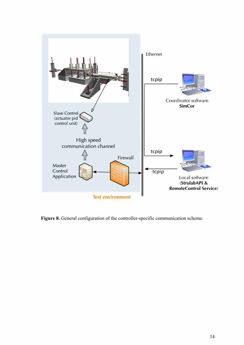
Laboratory of the University of Patras (Figures 8-9).
The smoothest way to introduce reference displacements to the host controller is when the
latter supports network communication. If this is the case, then the main concern is security
because with controllers functioning within a local laboratory network, risks maybe
encountered when they are exposed to a public network through which the reference signals
are received, Figure 8. Thus, any scheme for implementing hybrid simulation in modern
controllers should deal with the problem of riskless introduction of reference command
signals from the public to the local network. For this purpose, a MATLAB-based parenthetic
application (StrulabAPI) was built, running on a machine in the public network, but
communicating with both the remote server running UI-SimCor (via a network card
configured on the public network) and the control application (master controller) in the
laboratory (via a second network card on the same machine, but configured on the local
network). The StrulabAPI application receives - through the public network - the target
displacement command from UI-SimCor and updates - through the local network - the
command displacement in the dual memory blocks of the master controller application. Any
updating of the dual memory is instantly seen by the control unit operating the actuator (Fig.
8) and proceeds in applying the displacement command received. Any modifications which
need to be realized on the target displacement received from UI-SimCor is performed within
StrulabAPI: these may include scaling (if the specimen is in different scale with respect to the
analytical substructures) and geometric transformation (in case the reference coordinate
system of the target displacement does not coincide with the current actuator axis). More
details can be found in Bousias et al. (2014).
14
Figure 8. General configuration of the controller-specific communication scheme.

15
Figure 9. General configuration of the analog-input scheme.
For controllers without networking capabilities, as is the case for most controllers in
structural laboratories, the analog-input option, which is available in almost all of them, may
be explored: i.e. the capability to accept external input in the form of an analog signal. The
approach developed at the consortium-partner University of Toronto was used: target
displacements sent out by UI-SimCor were received by a purpose-built application [Network
Interface for Controllers – NICON, (Kammula et al. 2014; Zhan and Kwon 2015)] in
LabVIEW environment.

16
(a)
(b)
Figure 10. Experimental component: (a) displacement, and (b) force-displacement response.
The displacement command received (in digital form) from the network is directed by
NICON to a digital–to–analog (DAC) unit and the scaled analog output signal is hard-wired
from this unit to the analog input terminal of the actuator controller, as reference
displacement (or force) value, Figure 9. Upon execution of the command signal, the opposite
route is followed: the measured reaction force is directed (in analog form) to an analog–to–
digital converter (ADC) with the resulting digital signal being sent to the simulation
coordination software via the NICON. Νo compensation due to the network (varying) time
was introduced in the experimental module as all rate-dependent effects on the force response
of the isolator were compensated via the characterization process.
0 100 200 300 400 500 600 700 800 900 100060
40
20
0
20
40
60
Simulation Steps
Dis
plac
emen
t (m
m)
NICON
StrulabAPI
60 40 20 0 20 40 60800
600
400
200
0
200
400
600
Displacement (mm)
Res
tori
ng F
orce
(kN
)
NICON
StrulabAPI

17
Displacement (Figure 10(a)) and force-displacement response (Figure 10(b)) obtained from
each approach, i.e. the “analog-in” (NICON) and the Matlab script (StrulabAPI), are
compared. It is shown that displacements obtained by the two approaches practically coincide
and force-displacement loops compare very well – the asymmetry in the force-displacement
response is due to bearing damage owing to previous tests. However, what is not depicted in
these figures is that steps are completed faster in the analog-input” (NICON) approach – this
is elaborated in the following section along with other time-related issues.
4. HYBRID SIMULATION CASES AND RESULTS
4.1 Hybrid simulation cases
After deciding the geographical distribution of the modules and the experimental setup of
the bearings, four types of experiments were conducted among the partners, as summarized in
Table 1, namely, (a) Intercontinental multi-platform simulation (IMPS), (b) Hybrid
simulation at the University of Patras only (HSUPAT), (c) Hybrid Test between University of
Patras and Aristotle University (HTGR), and (d) Intercontinental Hybrid Test (IHT). The El
Centro earthquake record was used for all the aforementioned experiments. A total number of
1000 steps were executed while the time step was set equal to 0.01sec.
Table 1. Alternative configurations and roles among the geographically distributed remote
sites.
IMPS HTUPAT HTGR IHT
Module 1 AUTH UPATRAS AUTH AUTH
Module 2 UIUC UPATRAS AUTH UIUC
Module 3 USANNIO UPATRAS AUTH USANNIO
Module 4 UPATRAS UPATRAS UPATRAS UPATRAS
Module 5 U of T UPATRAS AUTH U of T
Coordinator AUTH UPATRAS AUTH AUTH
4.2 Comparison of results from different analysis cases
Figure 11 depicts the force-displacement loops for module 4 (left bearing) and the first
three simulations (HSUPAT, HTGR, IHT). It is observed that, despite the system sub-
structuring to sites widespread all over the world, the results of the local hybrid simulation
(HSUPAT), the Thessaloniki-Patras hybrid test (HTGR) and the Intercontinental Hybrid Test
(IHT) lead almost identical results.

18
Figure 11. Comparison of the force–displacement loops for the three experiments.
4.3 Observed distribution of communication delays
To study the sensitivity of the total time ttot required for completing each step on various
network-related and analysis parameters, the individual sources of delay had to be identified
and measured for each one of the n=5 remote sites involved and their four different
configurations summarized in Table 1, namely (a) the time, t1, required for the finite element
analysis at a given step, (b) the time required to communicate target commands to each
substructure, t2,n, (c) the time t3,n for completing the individual (numerical or experimental)
operations at a sub-structure level of the respective remote site; (d) the time, t4,n, required for
the analysis coordinator to receive measured values and (e) tnet the pure networking (internet)
time spent in transmitting the data along the various to remote modules worldwide.
Figure 12. Schematic representation of operations and time duration within each time step
19
The disaggregation of the time step into individual modules for the three main cases of
multi-platform simulation (IMPS), and hybrid testing at a national (HTGR) and
intercontinental level (IHT) is presented in Figure 12. It is noted that the time indicated in the
graphs for each one of the n modules (remote sites) is the sum of communication and
operation time, t2,n+t3,n+t4,n.
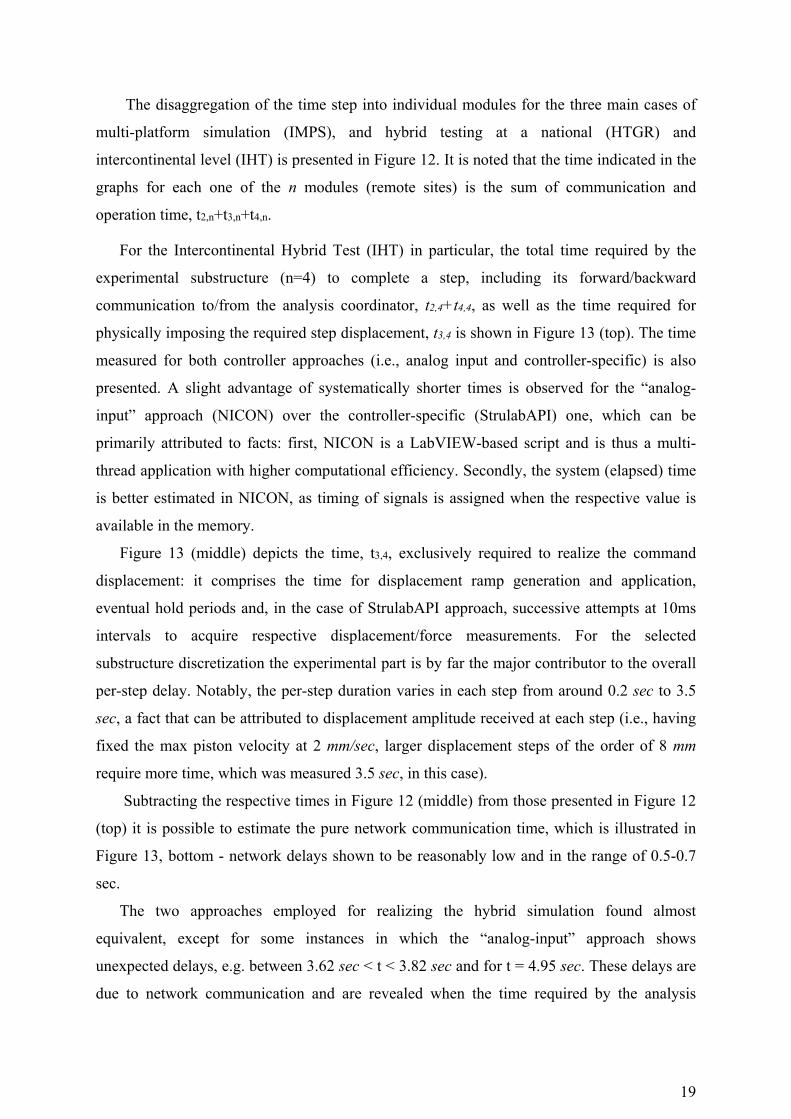
For the Intercontinental Hybrid Test (IHT) in particular, the total time required by the
experimental substructure (n=4) to complete a step, including its forward/backward
communication to/from the analysis coordinator, t2,4+t4,4, as well as the time required for
physically imposing the required step displacement, t3,4 is shown in Figure 13 (top). The time
measured for both controller approaches (i.e., analog input and controller-specific) is also
presented. A slight advantage of systematically shorter times is observed for the “analog-
input” approach (NICON) over the controller-specific (StrulabAPI) one, which can be
primarily attributed to facts: first, NICON is a LabVIEW-based script and is thus a multi-
thread application with higher computational efficiency. Secondly, the system (elapsed) time
is better estimated in NICON, as timing of signals is assigned when the respective value is
available in the memory.
Figure 13 (middle) depicts the time, t3,4, exclusively required to realize the command
displacement: it comprises the time for displacement ramp generation and application,
eventual hold periods and, in the case of StrulabAPI approach, successive attempts at 10ms
intervals to acquire respective displacement/force measurements. For the selected
substructure discretization the experimental part is by far the major contributor to the overall
per-step delay. Notably, the per-step duration varies in each step from around 0.2 sec to 3.5
sec, a fact that can be attributed to displacement amplitude received at each step (i.e., having
fixed the max piston velocity at 2 mm/sec, larger displacement steps of the order of 8 mm
require more time, which was measured 3.5 sec, in this case).
Subtracting the respective times in Figure 12 (middle) from those presented in Figure 12
(top) it is possible to estimate the pure network communication time, which is illustrated in
Figure 13, bottom - network delays shown to be reasonably low and in the range of 0.5-0.7
sec.
The two approaches employed for realizing the hybrid simulation found almost
equivalent, except for some instances in which the “analog-input” approach shows
unexpected delays, e.g. between 3.62 sec < t < 3.82 sec and for t = 4.95 sec. These delays are
due to network communication and are revealed when the time required by the analysis

20
engine, t1, (time-difference between receiving the response from the last module, n=5, until
the next command to the first module, n=1, is sent) and the ramp/hold time in the
experimental module are subtracted from the total time step duration. Even though the
sporadic presence of this delay is not expected to introduce any major error in the response of
the bridge at a system level, its unpredictable nature highlights the necessity for further
studies to identify and minimize network latency particularly when the remote sites are
widely separated, rate-dependent phenomena are involved and RTDS is pursued.
Another interesting aspect is the time required for the analysis coordinator UI-SimCor to
communicate with each one of the five modules (substructures) for the three main
configurations of the intercontinental multiplatform simulation (IMPS), the national hybrid
testing (HTGR) and the Intercontinental Hybrid Testing (IHT). It is noted that in this case
communication time refers not only to the network delays but also to the required time for the
numerical analysis or the execution of the experiment to proceed by one time step as well as
the “waiting” time of each module until UI-SimCor sends/ receives data in a series way
(predetermined order of modules).

21
Figure 13. IHT: per step duration in the experimental module: total time, t2,4+t3,4+t4,4 (top); ramp-and-hold duration per step, t3,4 (middle); communication time per step, t2,4+t4,4 (bottom).

22
Figure 14. Communication time (t2,n+t3,n+t4,n) for the Intercontinental Multi-Platform Simulation (IMPS, top), Hybrid Test between Greek partners (HTGR, middle) and the
Intercontinental Hybrid Test (IHT, bottom).

23
Table 2. Statistical distributions and sources of variation for the communication time of each
module for the IHT.
Modules Location of remote sites
Distribution observed
Distribution parameters
(sec), t2,n+t3,n+t4,n
Network delay, t2,n+t4,n
Experimental delay,
t3,n
CPU Time,
t3,n Coordinator AUTH ‐ ‐ Module 1
(Deck/Elastic) AUTH Normal
μ=0.21 σ=0.06
- - x
Module 2 (Left Pier, Nonlinear)
UIUC Log-normal μ=0.35 σ=0.12
x - x
Module 3 (Right Pier, Nonlinear)
USANNIO Log-normal μ=0.32 σ=0.16
x - x
Module 4 (Left Bearing, Nonlinear)
UPATRAS Log-normal μ=0.78 σ=0.52
x x
Module 5 (Right Bearing, Nonlinear)
UofT Log-normal μ=0.28 σ=0.11
x - x
As shown in Figure 14, in the case of multi-platform simulation (IMPS), the numerical
part at the most distant module from the analysis coordinator (i.e., Univ. of Illinois at Urbana-
Champaign) in Module 2 required more time to communicate with UI-SimCor per time step,
which is natural since the analysis coordinator was running in Europe. This is also an
indication that the roles between different remote sites and particularly that of the coordinator
should be very carefully selected based on preliminary parametric studies.
For the two national and intercontinental hybrid tests (Figure 14 middle and bottom), it is
evident that the experimentally tested component (left bearing, Module 4), needed more time
to establish communication with UI-SimCor, which is also quite anticipated since the time
measured includes the execution of the experimental step.
A final issue that was studied is the variation of time delay along the entire duration of the
Intercontinental Hybrid Test (IHT). This is deemed an important information as highly
dispersed times required to accomplish a time step are deemed prohibitive for studying
problems that are strongly rate-dependent. The statistical distribution of the communication
time per step of the individual modules for the Intercontinental Hybrid Test was then
examined considering three sources of variation, namely, network delay, experimental delay
and CPU time of the numerical analysis, the latter including the effect of nonlinear soil, pier
or bearing response under stronger ground motions in the involved sites. Table 2 summarizes
the observed distributions and the sources of variation for the communication of all modules
this test as well as the sites where the response was nonlinear.

24
It is seen that the communication time of Module 1 (i.e. numerically analyzing the bridge
deck) follows a normal distribution (with mean value μ=0.21sec and standard deviation
σ=0.06sec). For this very example, since Module 1 is numerically analyzed locally and the
deck remains elastic during the hybrid test, the only source of variation is attributed to the
CPU procedures in the computer station used for the coordination and the analysis of the
hybrid simulation. Naturally, the coefficient of variation C.O.V. of the time required per step
is kept reasonably low (0.28). Mean times and standard deviations are higher for sites running
numerical analysis of substructures that exhibit nonlinear response as also shown in Table 2,
corresponding to cov values between 0.35-0.50, while following a rather uniform
distribution. As anticipated, the communication time of the experimental component (i.e.
Module 4: left bearing), which integrates experimental and communication sources of
variation, follows a log-normal distribution with μ=0.18 and σ=0.52.
6. CONCLUSIONS
This paper investigates the effect of remote host distance on the feasibility, accuracy and
performance of hybrid simulation among long-separated sites. Both geographically
distributed multi-platform analysis and hybrid simulations were performed for the case of a
real three-span reinforced concrete bridge between European and North American partners.
Two different approaches employed for implementing hybrid simulation. In the first, a fully
featured controller was employed, while in the second the “analog-input” approach was
selected. The component that was physically tested was the bearing located at the left bridge
abutment, while the complementary superstructure components were numerically analyzed.
It is concluded from this study that an intercontinental experiment among five sites can be
performed successfully (at a time expansion of 150-250 times), thus highlighting the
increasing capabilities of geographically distributed hybrid simulation. It was also proven
feasible to implement tools and procedures that are not tailored to the existing equipment in
Europe after appropriate hardware and software adaptations at the local host.
From a technical point of view, the two approaches employed for realizing the hybrid
simulation (i.e., fully featured controller versus “analog-input” method) were almost equally
efficient, except for some instances in which the latter showed unexpected delays. These
delays are due to network communication and are uncovered when the time required by the
analysis engine and the ramp/hold time in the experimental module are subtracted from the
total time step duration.

25
Clearly, the distance among remote hosts remains a crucial factor considering future
Real-Time Hybrid Testing experiments particularly for studying rate-dependent physical
problems among sites at great distance. This is because the time expansion tolerance of rate
sensitive components or devices is counteracted by the network latency, which can only be
reduced at a certain degree (particularly in terms of signals crossing the Atlantic).
On the other hand, the observation that the communication time followed certain
distributions around the mean might be a useful tool in compensating for the related
uncertainty while designing similar experiments. Overall, the intercontinental hybrid
experiment was accomplished and repeated successfully, highlighting the robustness,
efficiency and repetitiveness of the approach. However, further research is needed to
minimize uncertainties, and optimize the efficiency of the communicating algorithms both at
the site level and for the coordination of the multiple sites.
ACKNOWLEDGMENTS
This work carried out was funded by the 7th Framework Programme of the European
Commission, under the PIRSES-GA-2009-247567-EXCHANGE-SSI grant (Experimental &
Computational Hybrid Assessment Network for Ground-Motion Excited Soil-Structure
Interaction Systems, www.exchange-ssi.net). The authors would also like to thank Prof. Alain
Pecker for his valuable comments during the project.
REFERENCES
ABAQUS [2010] "User’s manual," Hibbit, Karlsson and Sorensen Inc., Rhode Island, USA.
Bousias, S., Kwon, O-S, Evangeliou, N., Sextos, A. and Taskari, O. [2014] "Implementation issues in distributed hybrid simulation," 6th World Conf. of Structural Control and Monitoring, Barcelona, Spain.
Carrion, J., Spencer, B., and Phillips, B. (2009). “Real-time hybrid simulation for structural control performance assessment.” Earthquake Engineering and Engineering Vibration, 8(4), 481–492.
CEN. (2005). European Standard EN 1998-2. Eurocode 8: Design of structures for earthquake resistance — Part 2 Bridges, Committee for Standarization. Brussels, Belgium.
Chae, Y., Ricles, J., and Sause, R. (2014). “Large-scale real-time hybrid simulation of a three-story steel frame building with magneto-rheological dampers.” Earthquake Engineering & Structural Dynamics.
Chen, C., and Ricles, J. M. (2009). “Improving the inverse compensation method for real-
26
time hybrid simulation through a dual compensation scheme.” Earthquake Engineering & Structural Dynamics, 38, 1237–1255.
Chen, P., Tsai, K., and Lin, P. (2014). “Real-time hybrid testing of a smart base isolation system.” Earthquake, 43, 139–158.
Dion, C., Bouaanani, N., Tremblay, R., Lamarche, C. P., and Leclerc, M. (2010). “Real-time hybrid testing of seismic protective systems for bridge structures.” 9th US National and 10th Canadian Conference on Earthquake Engineering: Reaching Beyond Borders, Toronto, Canada, 25-29 July.
Dorka, U. (1995). “Friction Device for protection of structural systems against dynamic actions.” Patent Number 5456047. United States Patent.
Earthquake Planning and Protection Organization (EPPO). (2000). “Greek Seismic Code EAK2000 (amended in 2003), Athens, Greece (in Greek).” Athens.
Elnashai, A., Papanikolaou, V., and Lee, D. (2002). Zeus NL – A System for Inelastic Analysis of Structures. Univ. of Illinois at Urbana-Champaign.
Elnashai, A. S., Spencer, B. F., Kim, S. J., Holub, C. J., and Kwon, O. S. (2008). “Hybrid distributed simulation of a bridge-foundation-soil interacting system.” The 4th International Conference on Bridge Maintenance, Safety, and Management, Seoul, Korea.
FEMA440. (2004). “NEHRP Recommended provisions for seismic regulations for new buildings and other structures.”
Filippou, F., and Constantinides, M. (2004). FEDEASLab Getting Started Guide and Simulation Examples.
Hibbit, K., and Sorenson, N. (2006). ABAQUS ver. 6.6, User’s Manual. Pawtucket, USA.
Kammula, V., Erochko, J., Kwon, O. S., and Christopoulos, C. (2014). “Application of hybrid-simulation to fragility assessment of the telescoping self-centering energy dissipative bracing system.” Earthquake Engineering and Structural Dynamics.
Kwon, O.-S., Elnashai, A. S., Spencer, B. F., O.-S. Kwon, Elnashai, A. S., and Spencer, B. F. (2008). “A framework for distributed analytical and hybrid simulaitons.” Structural Engineering and Mechanics, 30(3), 331–350.
Kwon, O.-S., Elnashai, A. S., Spencer, B. F., and Park, K. (2007). “UI-SIMCOR : A global platform for hybrid distributed simulation.” 9th Canadian Conference on Earthquake Engineering, Ontario, Canada, 139–149.
Kwon, O.-S., Nakata, N., Elnashai, A., and Spencer, B. (2005). “A framework for multi-site distributed simulation.” Journal of Earthquake Engineering, 9(5), 741–753.
Mander, J. B., Priestley, M. J. N., and Park, R. (1988). “Theoretical Stress‐Strain Model for Confined Concrete.” Journal of Structural Engineering, 114(8), 1804–1826.
McKenna, F., Fenves, G., and Scott, M. (2002). Open system for earthquake engineering simulation. University of California, Berkeley.
Ministry of Public Works of Greece. (1999). Circular E39/99: Guidelines for Seismic Design of Bridges, Athens (in Greek).
Molina, F. J. (2002). “Pseudodynamic tests on rubber base isolators with numerical substructuring of the superstructure and strain-rate effect compensation.” Earthquake Engineering & Structural Dynamics, 31(8), 1563–1582.

27
Mosqueda, G. (2006). “Fast Hybrid Simulation with Geographically Distributed Substructures.” Asce.
Mosqueda, G., and Stojadinović, B. (2008). “Hybrid seismic response simulation on a geographically distributed bridge model.” Journal of Structural Engineering, ASCE, 134(4), 535–543.
Mylonakis, G. E., Nikolaou, S., and Gazetas, G. (2006). “Footings under seismic loading: analysis and design issues with emphasis on bridge foundations.” Soil Dynamics and Earthquake Engineering, 26(9), 824–853.
Naeim, F., and Kelly, J. M. (1999). Design of Seismic Isolated Structures: From Theory to Practice. John Wiley and Sons, New York.
Nakashima, M., and Masaoka, N. (1999). “Real- time on-line test for MDOF systems.” Earthquake Engineering & Structural Dynamics, 28, 393–420.
Ojaghi, M., Martinez, I. L., Dietz, M., Williams, M. S., Blakeborough, A., Crewe, A., Taylor, C. E., Madabhushi, S. P. G., Haigh, S., and Ali, A. (2010). “UK-NEES-Distributed hybrid testing between Bristol, Cambridge and Oxford Universities: connecting structural dynamics labs to a geotechnical centrifuge.” 9th US National and 10th Canadian Conference on Earthquake Engineering: Reaching Beyond Borders, Toronto, Canada, 25-29 July.
Ojaghi, M., Williams, M. S., Dietz, M. S., Blakeborough, A., and Martínez, I. L. (2014). “Real-time distributed hybrid testing : coupling geographically distributed scienti fi c equipment across the Internet to extend seismic testing capabilities.” (November 2013), 1023–1043.
Pan, P., Tada, M., and Nakashima, M. (2005). “Online hybrid test by internet linkage of distributed test-analysis domains.” Earthquake Engineering & Structural Dynamics, 34(11), 1407–1425.
Saouma, V., Kang, D.-H., and Haussmann, G. (2012). “A computational finite-element program for hybrid simulation.” Earthquake Engineering & Structural Dynamics, 41, 375–389.
Schellenberg, A., Becker, T. C., and Mahin, S. A. (2014). “Development of a large scale hybrid shake table and application to testing a friction slider isolated system.” 10th National Conference on Earthquake Engineering, Anchorage, Alaska, U.S.
Schellenberg, A., Mahin, S. A., and Fenves, G. (2009). Advanced Implementation of Hybrid Simulation.
Spencer, B., Elnashai, A., Kuchma, D., Ricles, J., Sause, R., Abdoun, T., Kim, S., Holub, C., Roy, S., Radwan, H., Nakata, N., and Marullo, T. (2006). Multi-site soil-strucutre-foundation interaction test (MISST).
Spencer, B. F., Finholt, T., Foster, I., Kesselman, C., Beldica, C., Futrelle, J., Gullapalli, S., Hubbard, P., Liming, L., Marcusiu, D., Pearlman, L., and Severance, C. (2004). “NEESGRID : A distributed collaboratory for advanced earthquake engineering experiment and simulation.” 13 th World Conference on Earthquake Engineering, Vancouver, B.C., Canada.
Takahashi, Y., and Fenves, G. (2006). “Software framework for distributed experimental–computational simulation of structural systems.” Earthquake Engineering & Structural Dynamics, 35(3), 267–291.

28
Takahashi, Y., Iemura, H., Mahin, S., and Fenves, G. (2008). “International distributed hybrid simulation of 2-span continuous bridge.” 14th World Conference on Earthquake Engineering.
Taskari, O., and Sextos, A. G. (2013). “Robustness, Repeatability and Resilience of Intercontinetal Distributed Computing for the purposes of Seismic Assessment of Bridges.” 4th ECCOMMAS Thematic Conference on Computational Methods in Structural Dynamics and Earthquake Engineering, Kos Island, Greece, 12-14 June 2013.
Taskari, O., and Sextos, A. G. (2015). “Probabilistic assessment of abutment-embankment stiffness and implications in the predicted performance of short bridges.” Journal of Earthquake Engineering, 19(5), 822-846. .
Taucer, F., Spacone, E., and Filippou, F. (1991). A fiber beam-column element for seismic response analysis of reinforced concrete structures, Report No. UCB/EERC-91/17, Earthquake Eng. Research Center, University of California at Berkeley, CA, 1991.
Zhan, H., and Kwon, O.-S. (2015). “Actuator controller interface program for pseudo- dynamic hybrid simulation.” 2015 World Congress on Advances in Structural Engineering and Mechanics, Songdo, Korea.
Zhan, H. and Kwon, O. [2015] "Actuator controller interface program for pseudo-dynamic hybrid simulation," Advances in Structural Engineering Mechanics, Songdo, Korea, Aug. 25-29.