
03 Numeric Basics
68
Digital Design: An Embedded Systems Approach Using Verilog Chapter 3 Numeric Basics Portions of this work are from the book, Digital Design: An Embedded Systems Approach Using Verilog, by Peter J. Ashenden, published by Morgan Kaufmann Publishers, Copyright 2007 Elsevier Inc. All rights reserved.
description
numrical approach
Transcript of 03 Numeric Basics
Digital Design:An Embedded Systems Approach Using Verilog
Chapter 3Numeric Basics
Portions of this work are from the book, Digital Design: An Embedded Systems Approach Using Verilog, by Peter J. Ashenden, published by Morgan Kaufmann Publishers, Copyright 2007 Elsevier Inc. All rights reserved.
Verilog
Digital Design — Chapter 3 — Numeric Basics 2
Numeric Basics Representing and processing
numeric data is a common requirement unsigned integers signed integers fixed-point real numbers floating-point real numbers complex numbers
Verilog
Digital Design — Chapter 3 — Numeric Basics 3
Unsigned Integers Non-negative numbers (including 0)
Represent real-world data e.g., temperature, position, time, …
Also used in controlling operation of a digital system
e.g., counting iterations, table indices Coded using unsigned binary (base
2) representation analogous to decimal representation
Verilog
Digital Design — Chapter 3 — Numeric Basics 4
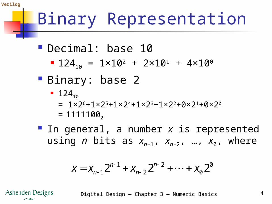
Binary Representation Decimal: base 10
12410 = 1×10² + 2×101 + 4×100
Binary: base 2 12410
= 1×26+1×25+1×24+1×23+1×22+0×21+0×20
= 11111002
In general, a number x is represented using n bits as xn–1, xn–2, …, x0, where
00
22
11 222 xxxx n
nn
n
Verilog
Digital Design — Chapter 3 — Numeric Basics 5
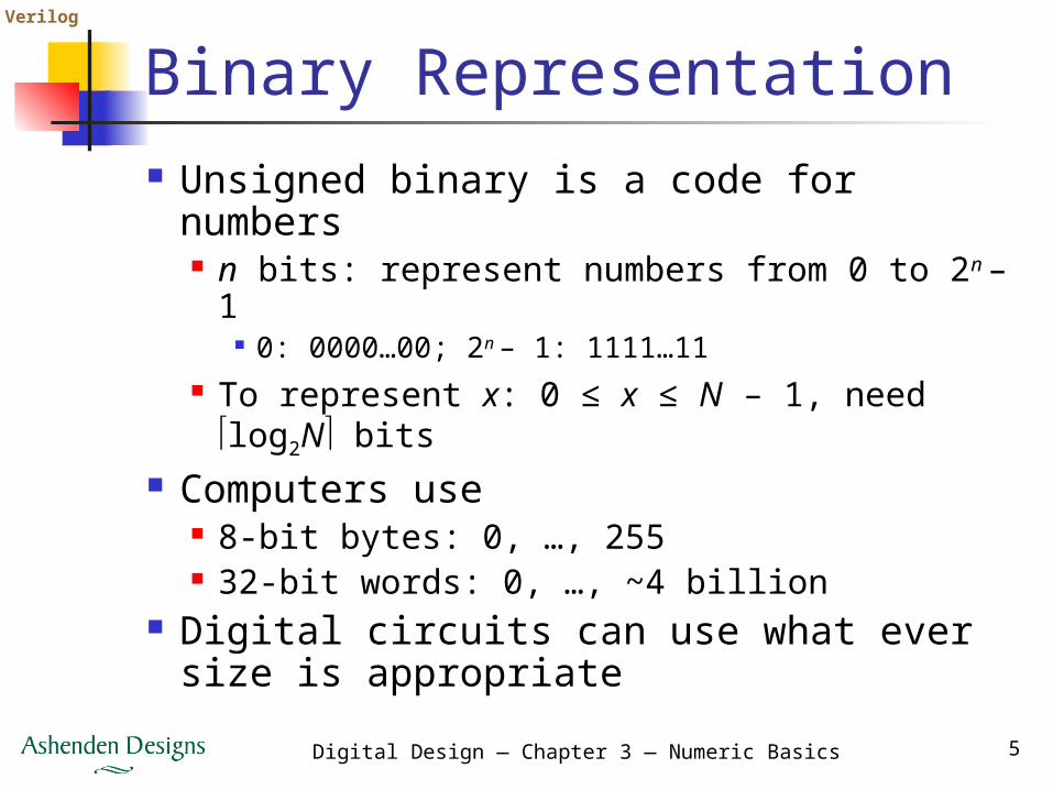
Binary Representation Unsigned binary is a code for numbers
n bits: represent numbers from 0 to 2n – 1 0: 0000…00; 2n – 1: 1111…11
To represent x: 0 ≤ x ≤ N – 1, need log2N bits
Computers use 8-bit bytes: 0, …, 255 32-bit words: 0, …, ~4 billion
Digital circuits can use what ever size is appropriate
Verilog
Digital Design — Chapter 3 — Numeric Basics 6
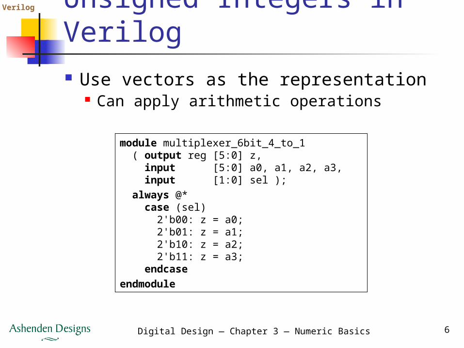
Unsigned Integers in Verilog Use vectors as the representation
Can apply arithmetic operationsmodule multiplexer_6bit_4_to_1 ( output reg [5:0] z, input [5:0] a0, a1, a2, a3, input [1:0] sel ); always @* case (sel) 2'b00: z = a0; 2'b01: z = a1; 2'b10: z = a2; 2'b11: z = a3; endcaseendmodule
Verilog
Digital Design — Chapter 3 — Numeric Basics 7
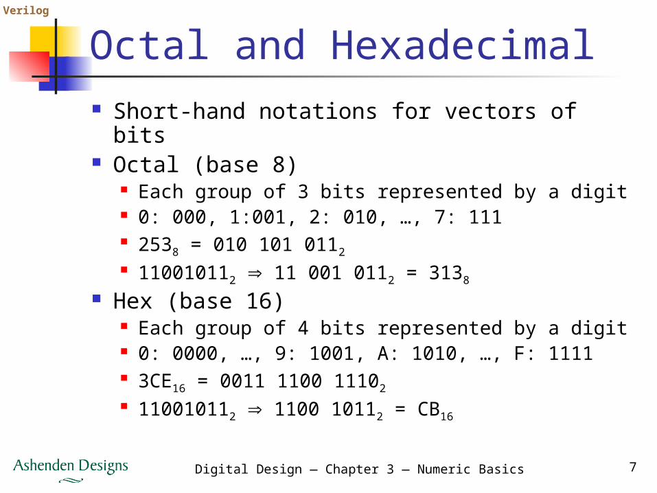
Octal and Hexadecimal Short-hand notations for vectors of bits Octal (base 8)
Each group of 3 bits represented by a digit 0: 000, 1:001, 2: 010, …, 7: 111 2538 = 010 101 0112 110010112 11 001 0112 = 3138
Hex (base 16) Each group of 4 bits represented by a digit 0: 0000, …, 9: 1001, A: 1010, …, F: 1111 3CE16 = 0011 1100 11102 110010112 1100 10112 = CB16
Verilog
Digital Design — Chapter 3 — Numeric Basics 8
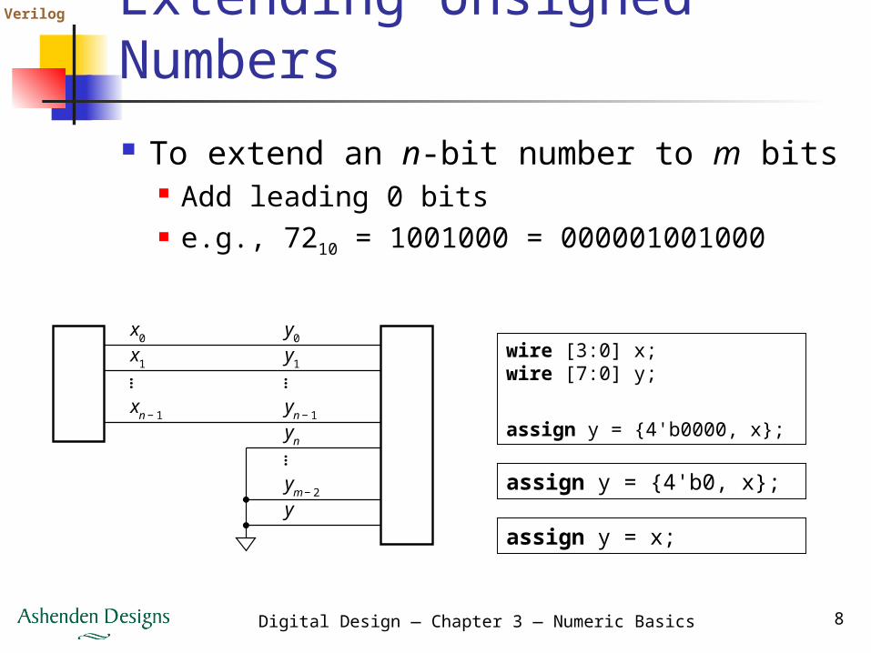
Extending Unsigned Numbers To extend an n-bit number to m bits
Add leading 0 bits e.g., 7210 = 1001000 = 000001001000
wire [3:0] x;wire [7:0] y;
assign y = {4'b0000, x};
assign y = {4'b0, x};
assign y = x;
x0
… ……
x1
xn − 1
y0
y1
yn − 1
yn
ym − 2
y
Verilog
Digital Design — Chapter 3 — Numeric Basics 9
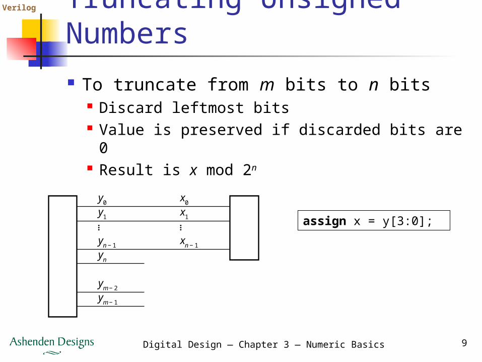
Truncating Unsigned Numbers To truncate from m bits to n bits
Discard leftmost bits Value is preserved if discarded bits are 0 Result is x mod 2n
assign x = y[3:0];…
y0
y1
yn − 1
x0
x1
xn − 1
yn
ym − 2
ym − 1
…
Verilog
Digital Design — Chapter 3 — Numeric Basics 10
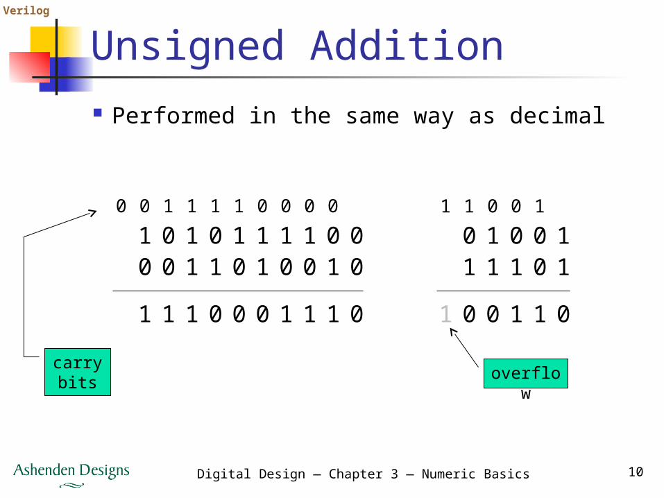
Unsigned Addition Performed in the same way as decimal
overflow
carry bits
1 0 1 0 1 1 1 1 0 0
1 1 1 0 0 0 1 1 1 0
0 0 1 1 0 1 0 0 1 0
0 0 1 1 1 1 0 0 0 0
0 1 0 0 1
0 0 11 1 0
1 1 1 0 1
1 1 0 0 1

Verilog
Digital Design — Chapter 3 — Numeric Basics 11
Addition Circuits Half adder
for least-significant bits
Full adder for remaining bits
000 yxs
001 yxc
iiii cyxs
iiiiii cyxyxc 1
xi yi ci si ci+1
0 0 0 0 0
0 0 1 1 0
0 1 0 1 0
0 1 1 0 1
1 0 0 1 0
1 0 1 0 1
1 1 0 0 1
1 1 1 1 1
Verilog
Digital Design — Chapter 3 — Numeric Basics 12
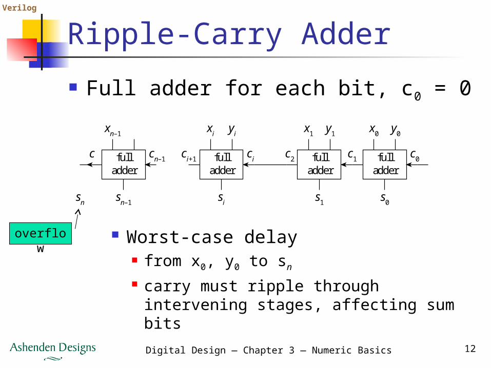
Ripple-Carry Adder Full adder for each bit, c0 = 0
overflow
Worst-case delay from x0, y0 to sn
carry must ripple through intervening stages, affecting sum bits
fulladder
xi
si
cici+1
yi
fulladder
x0
s0
c0c1
y0
fulladder
x1
s1
c2
y1
fulladder
xn–1
sn–1sn
cn–1c
Verilog
Digital Design — Chapter 3 — Numeric Basics 13
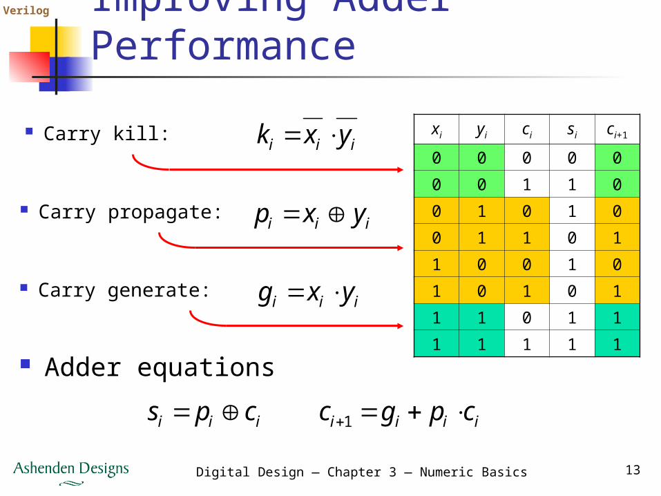
Improving Adder Performance
Carry kill: xi yi ci si ci+1
0 0 0 0 0
0 0 1 1 0
0 1 0 1 0
0 1 1 0 1
1 0 0 1 0
1 0 1 0 1
1 1 0 1 1
1 1 1 1 1
Carry propagate:
Carry generate:
iii yxk
iii yxp
iii yxg
Adder equationsiii cps iiii cpgc 1
Verilog
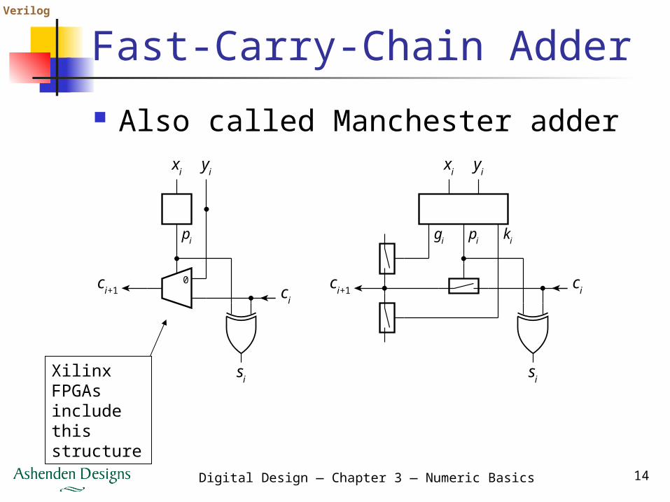
Digital Design — Chapter 3 — Numeric Basics 14
Fast-Carry-Chain Adder Also called Manchester adder
Xilinx FPGAs include this structure
xi
gi pi ki
si
cici+1
yixi
pi
si
ci
ci+1
yi
0
Verilog
Digital Design — Chapter 3 — Numeric Basics 15
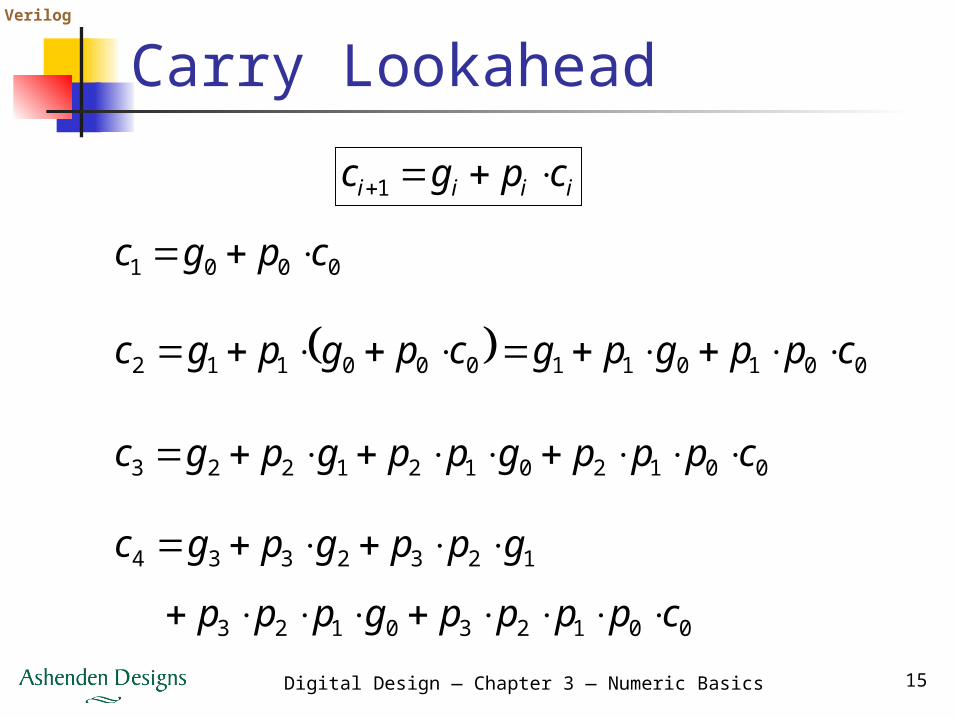
Carry Lookaheadiiii cpgc 1
0001 cpgc
001011000112 cppgpgcpgpgc
00120121223 cpppgppgpgc
001230123
1232334
cppppgppp
gppgpgc
Verilog
Digital Design — Chapter 3 — Numeric Basics 16
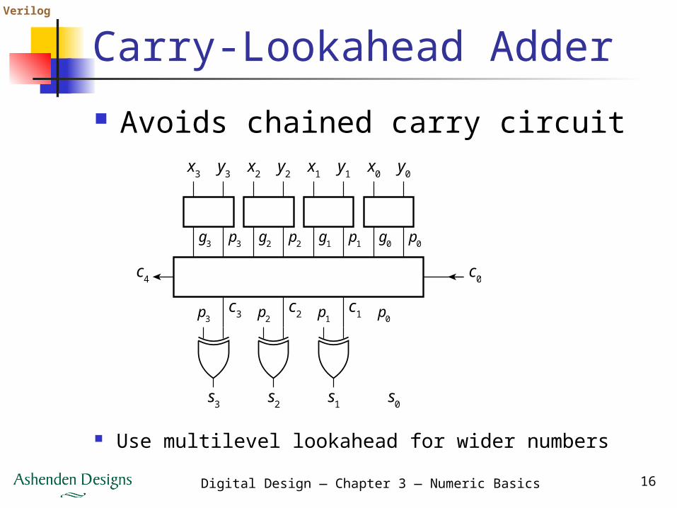
Carry-Lookahead Adder Avoids chained carry circuit
Use multilevel lookahead for wider numbers
x0
g0 p0
p3
s3
c0
c3
c4
y0x1
g1 p1
y1x2
g2 p2
y2x3
g3 p3
y3
p2
s2
c2 p1
s1
c1 p0
s0
Verilog
Digital Design — Chapter 3 — Numeric Basics 17
Other Optimized Adders Other adders are based on other
reformulations of adder equations Choice of adder depends on
constraints e.g., ripple-carry has low area, so is
ok for low performance circuits e.g., Manchester adder ok in FPGAs
that include carry-chain circuits
Verilog
Digital Design — Chapter 3 — Numeric Basics 18
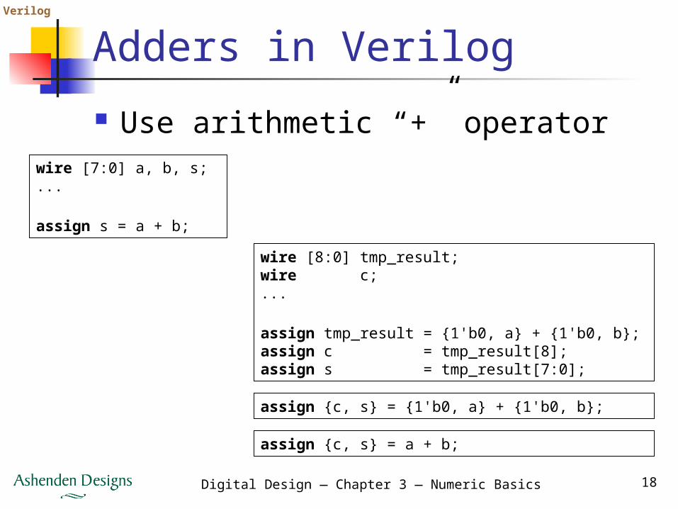
Adders in Verilog Use arithmetic “+” operator
wire [7:0] a, b, s; ...
assign s = a + b;
wire [8:0] tmp_result;wire c;...
assign tmp_result = {1'b0, a} + {1'b0, b};assign c = tmp_result[8];assign s = tmp_result[7:0];
assign {c, s} = {1'b0, a} + {1'b0, b};
assign {c, s} = a + b;
Verilog
Digital Design — Chapter 3 — Numeric Basics 19
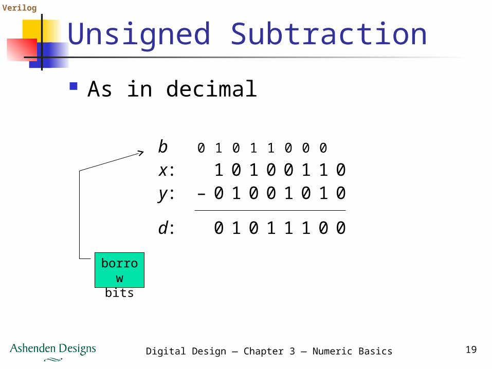
Unsigned Subtraction As in decimal
borrow bits
1 0 1 0 0 1 1 0
0 1 0 1 1 1 0 0
0– 1 0 0 1 0 1 0
0 1 0 1 1 0 0 0
x:y:
d:
b
Verilog
Digital Design — Chapter 3 — Numeric Basics 20
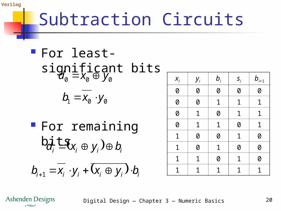
Subtraction Circuits For least-significant
bits
For remaining bits
000 yxd
001 yxb
iiii byxd
iiiiii byxyxb 1
xi yi bi si bi+1
0 0 0 0 0
0 0 1 1 1
0 1 0 1 1
0 1 1 0 1
1 0 0 1 0
1 0 1 0 0
1 1 0 1 0
1 1 1 1 1
Verilog
Digital Design — Chapter 3 — Numeric Basics 21
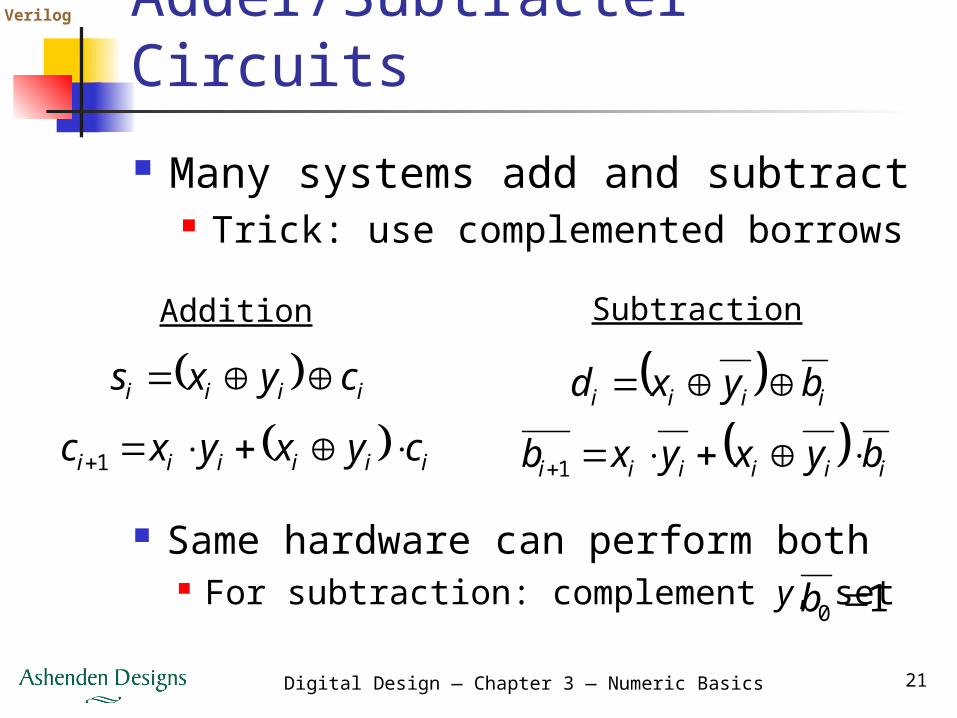
Adder/Subtracter Circuits Many systems add and subtract
Trick: use complemented borrows
iiii byxd
iiiiii byxyxb 1
iiii cyxs
iiiiii cyxyxc 1
Addition Subtraction
Same hardware can perform both For subtraction: complement y, set 10 b
Verilog
Digital Design — Chapter 3 — Numeric Basics 22
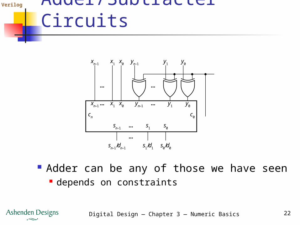
Adder/Subtracter Circuits
Adder can be any of those we have seen depends on constraints
y0y1yn–1
y0
c0cn
y1yn–1
…
…
…
…
x0x1xn–1
x0x1xn–1
… s0s1sn–1
sn–1/dn–1 s1/d1 s0/d0
…
Verilog
Digital Design — Chapter 3 — Numeric Basics 23
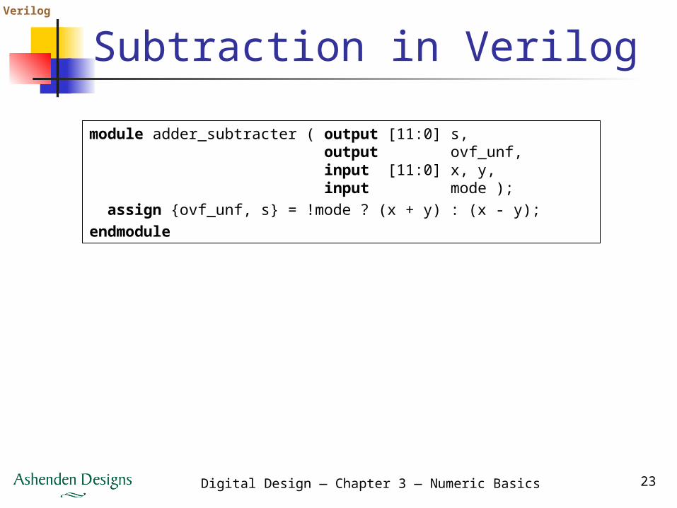
Subtraction in Verilogmodule adder_subtracter ( output [11:0] s, output ovf_unf, input [11:0] x, y, input mode ); assign {ovf_unf, s} = !mode ? (x + y) : (x - y);endmodule
Verilog
Digital Design — Chapter 3 — Numeric Basics 24
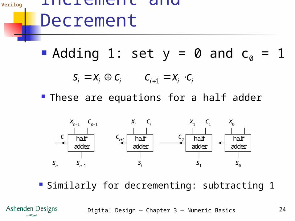
Increment and Decrement Adding 1: set y = 0 and c0 = 1
iii cxs iii cxc 1
These are equations for a half adder
Similarly for decrementing: subtracting 1
halfadder
xi
si
ci
ci+1 halfadder
x0
s0
c1
halfadder
x1
s1
c2halfadder
xn–1
sn–1sn
cn–1
c
Verilog
Digital Design — Chapter 3 — Numeric Basics 25
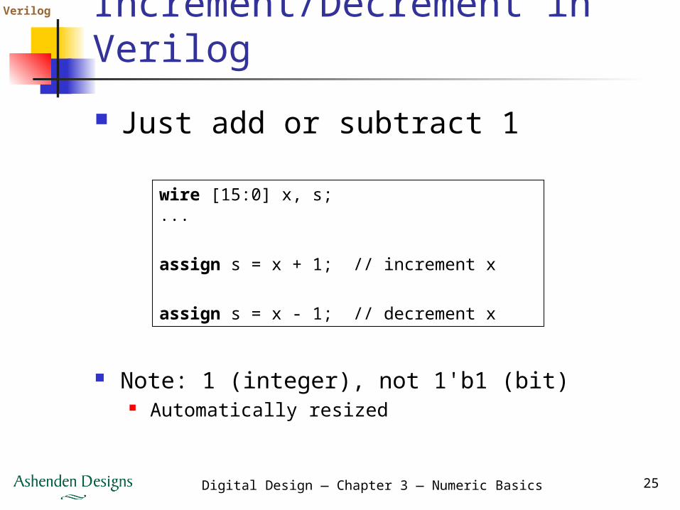
Increment/Decrement in Verilog Just add or subtract 1
wire [15:0] x, s;...
assign s = x + 1; // increment x
assign s = x - 1; // decrement x
Note: 1 (integer), not 1'b1 (bit) Automatically resized
Verilog
Digital Design — Chapter 3 — Numeric Basics 26
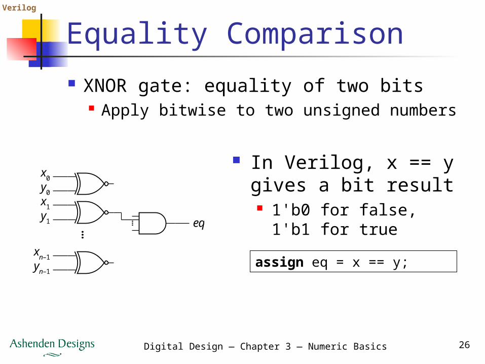
Equality Comparison XNOR gate: equality of two bits
Apply bitwise to two unsigned numbers
assign eq = x == y;
In Verilog, x == y gives a bit result 1'b0 for false, 1'b1 for
true
x0
eq…
y0x1y1
xn–1yn–1
…
Verilog
Digital Design — Chapter 3 — Numeric Basics 27
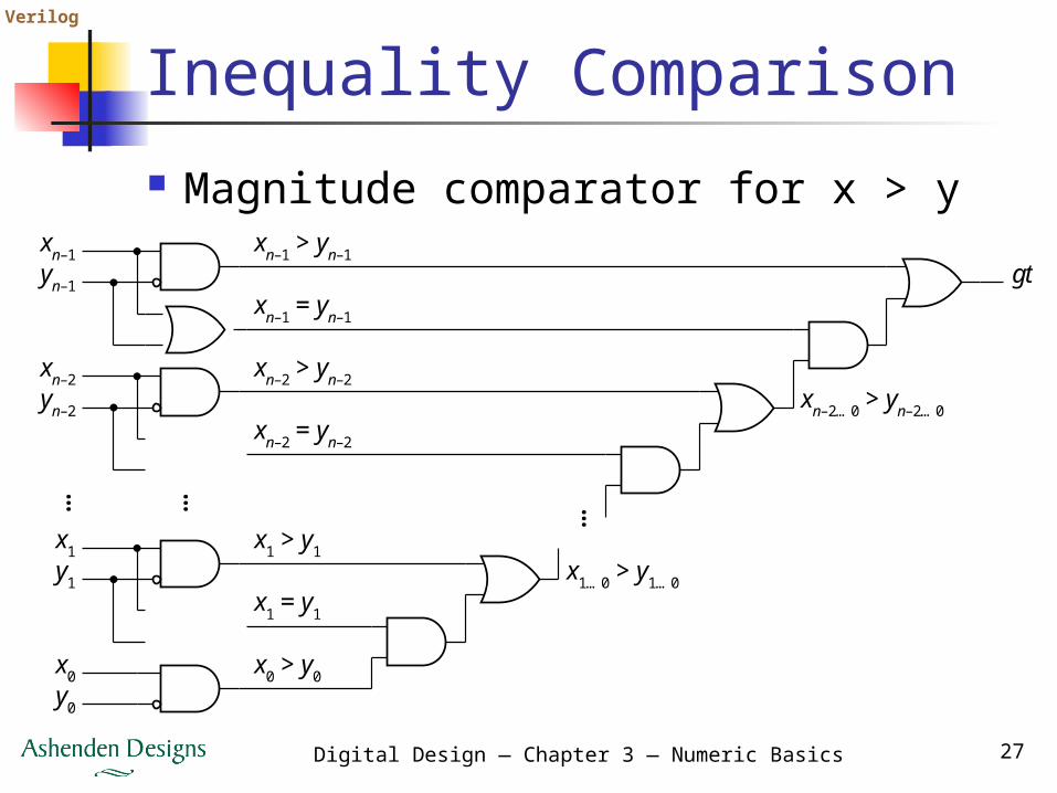
Inequality Comparison Magnitude comparator for x > y
xn–1gt
xn–1 > yn–1
xn–1 = yn–1
xn–2 > yn–2
xn–2 = yn–2
yn–1
xn–2yn–2
x1 > y1x1…0 > y1…0
xn–2…0 > yn–2…0
x1 = y1
x1y1
x0 > y0x0y0
…… …
Verilog
Digital Design — Chapter 3 — Numeric Basics 28
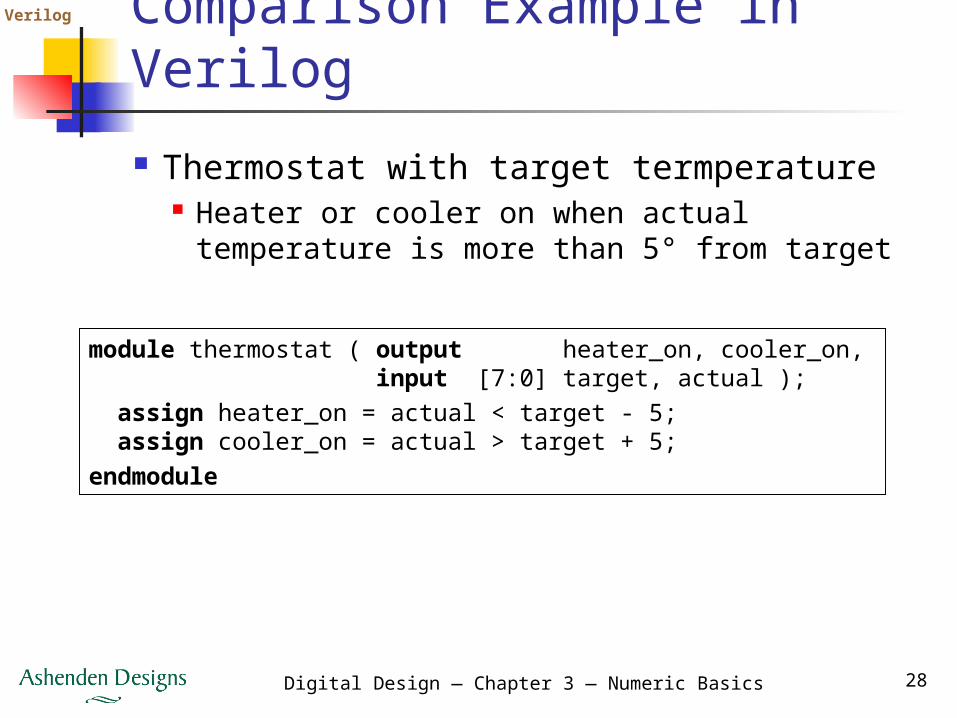
Comparison Example in Verilog Thermostat with target termperature
Heater or cooler on when actual temperature is more than 5° from target
module thermostat ( output heater_on, cooler_on, input [7:0] target, actual ); assign heater_on = actual < target - 5; assign cooler_on = actual > target + 5;endmodule
Verilog
Digital Design — Chapter 3 — Numeric Basics 29
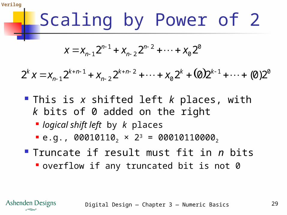
Scaling by Power of 2
This is x shifted left k places, with k bits of 0 added on the right logical shift left by k places e.g., 000101102 × 23 = 000101100002
Truncate if result must fit in n bits overflow if any truncated bit is not 0
00
22
11 222 xxxx n
nn
n
010
22
11 2)0(202222
kknkn
nkn
k xxxx

Verilog
Digital Design — Chapter 3 — Numeric Basics 30
Scaling by Power of 2
This is x shifted right k places, with k bits truncated on the right logical shift right by k places e.g., 011101102 / 23 = 011102
Fill on the left with k bits of 0 if result must fit in n bits
00
22
11 222 xxxx n
nn
n
kkk
knn
knn
k xxxxxx
222222/ 0
11
022
11
Verilog
Digital Design — Chapter 3 — Numeric Basics 31
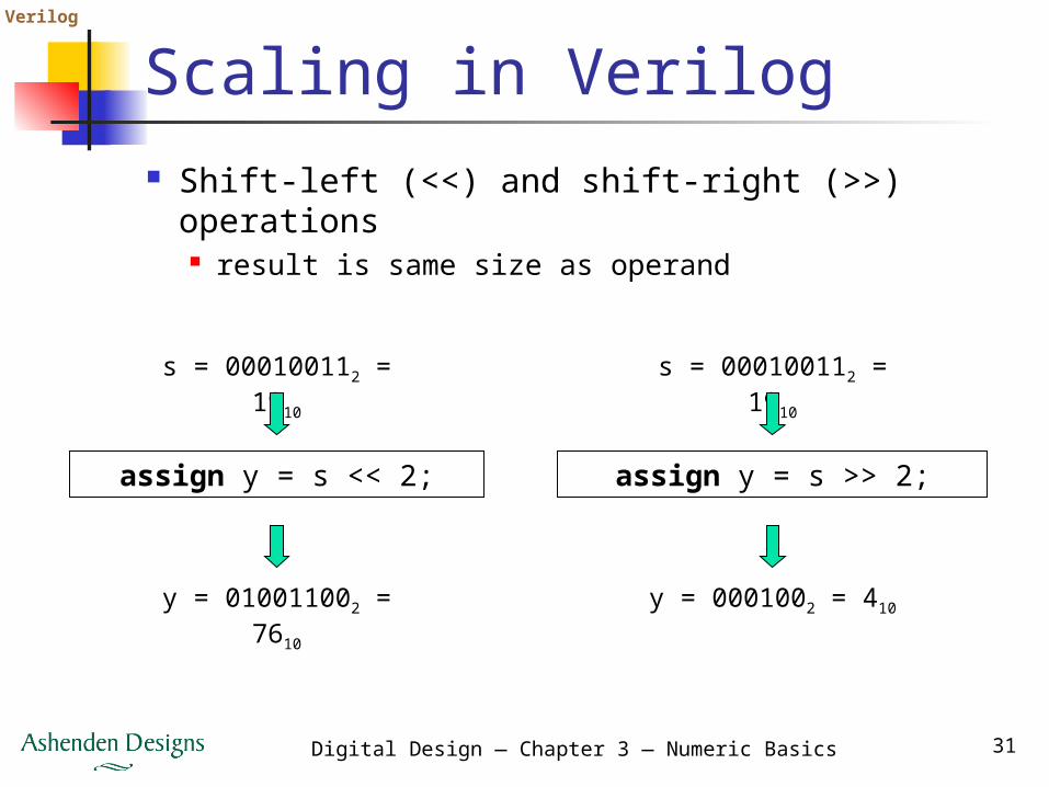
Scaling in Verilog Shift-left (<<) and shift-right (>>) operations
result is same size as operand
assign y = s << 2;
s = 000100112 = 1910
y = 010011002 = 7610
assign y = s >> 2;
s = 000100112 = 1910
y = 0001002 = 410
Verilog
Digital Design — Chapter 3 — Numeric Basics 32
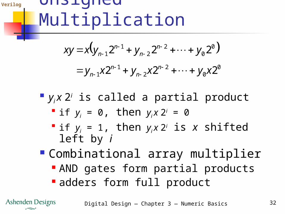
Unsigned Multiplication
yi x 2i is called a partial product if yi = 0, then yi x 2i = 0 if yi = 1, then yi x 2i is x shifted left by i
Combinational array multiplier AND gates form partial products adders form full product
0
02
21
1
00
22
11
222
222
xyxyxy
yyyxxyn
nn
n
nn
nn

Verilog
Digital Design — Chapter 3 — Numeric Basics 33
Unsigned Multiplication
Adders can be any of those we have seen
Optimized multipliers combine parts of adjacent adders
x0 y1x1xn–1
y0
c0cn
y1yn–1 yn–2
…
……
xn–2
x0x1xn–2
… s0s1s2
xn–1
…sn–1
… s1s2
…
… … …
sn–1
adder
x0 y2x1xn–1
y0
c0cn
y1yn–1 yn–2
…
………
xn–2
x0x1xn–2
s0
xn–1
…
adder
… s1s2
…sn–1
x0 y0x1xn–1
y0
c0cn
y1yn–1 yn–2
…
………
xn–2
x0x1xn–2
s0
xn–1
adder
… s1s2
…sn–1
x0 yn–1x1xn–1
y0
c0cn
y1yn–1 yn–2
…
………
xn–2
p0p1p2pn–1pnpn+1p2n–2p2n–1
x0x1x
Verilog
Digital Design — Chapter 3 — Numeric Basics 34
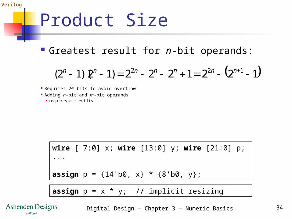
Product Size Greatest result for n-bit operands:
1221222)12)(12( 122 nnnnnnn
Requires 22n bits to avoid overflow Adding n-bit and m-bit operands
requires n + m bits
wire [ 7:0] x; wire [13:0] y; wire [21:0] p;...
assign p = {14'b0, x} * {8'b0, y};
assign p = x * y; // implicit resizing
Verilog
Digital Design — Chapter 3 — Numeric Basics 35
Other Unsigned Operations Division, remainder
More complicated than multiplication Large circuit area, power
Complicated operations are often performed sequentially in a sequence of steps, one per clock
cycle cost/performance/power trade-off

Verilog
Digital Design — Chapter 3 — Numeric Basics 36
Gray Codes Important for position encoders
Only one bit changes at a time
Segment
Code Segment
Code
0 0000 8 11001 0001 9 11012 0011 10 11113 0010 11 11104 0110 12 10105 0111 13 10116 0101 14 10017 0100 15 1000
See book for n-bit Gray code
Verilog
Digital Design — Chapter 3 — Numeric Basics 37
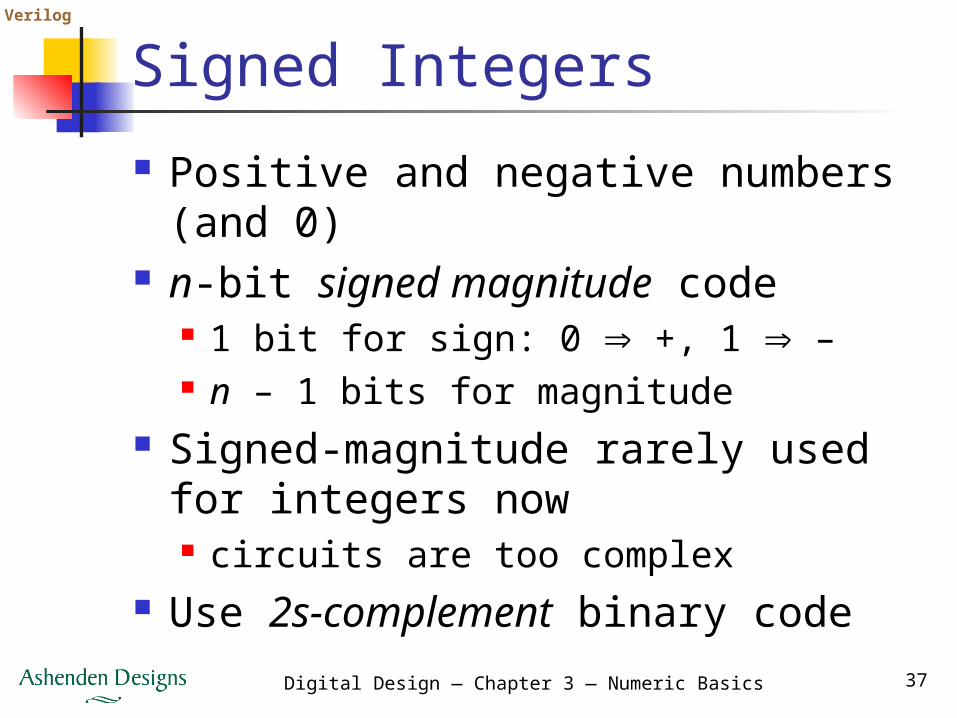
Signed Integers Positive and negative numbers (and
0) n-bit signed magnitude code
1 bit for sign: 0 +, 1 – n – 1 bits for magnitude
Signed-magnitude rarely used for integers now circuits are too complex
Use 2s-complement binary code
Verilog
Digital Design — Chapter 3 — Numeric Basics 38
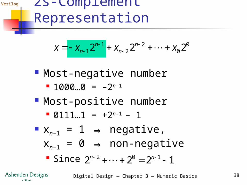
2s-Complement Representation
Most-negative number 1000…0 = –2n–1
Most-positive number 0111…1 = +2n–1 – 1
xn–1 = 1 ⇒ negative,xn–1 = 0 ⇒ non-negative Since
00
22
11 222 xxxx n
nn
n
1222 102 nn
Verilog
Digital Design — Chapter 3 — Numeric Basics 39
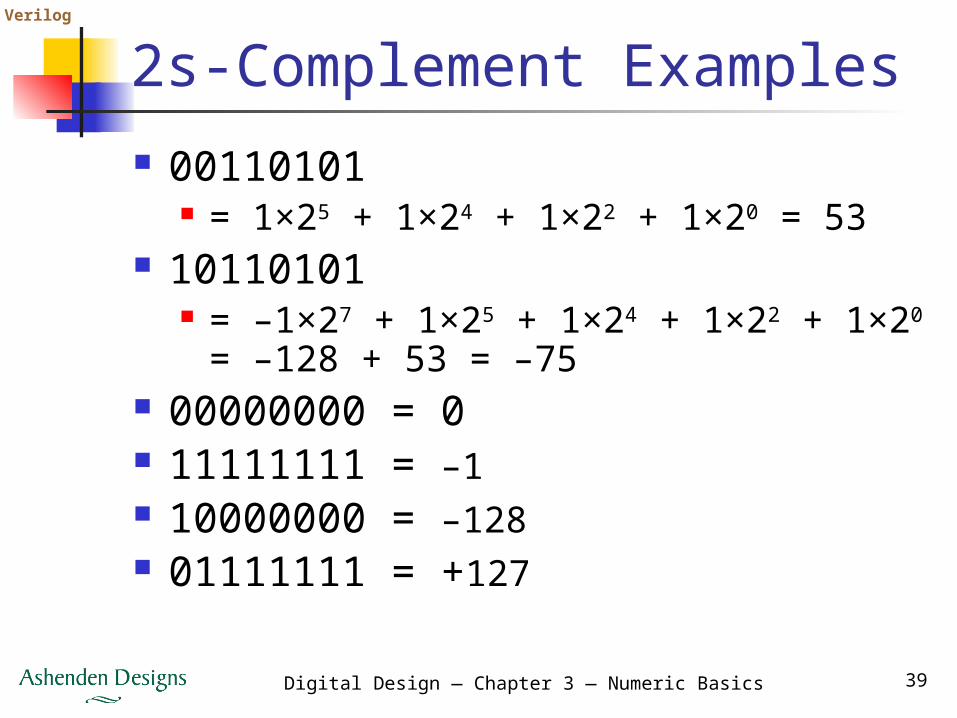
2s-Complement Examples 00110101
= 1×25 + 1×24 + 1×22 + 1×20 = 53 10110101
= –1×27 + 1×25 + 1×24 + 1×22 + 1×20
= –128 + 53 = –75 00000000 = 0 11111111 = –1 10000000 = –128 01111111 = +127
Verilog
Digital Design — Chapter 3 — Numeric Basics 40
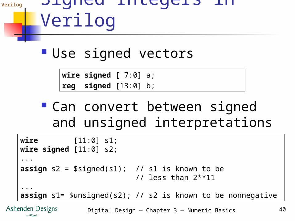
Signed Integers in Verilog Use signed vectors
wire signed [ 7:0] a;reg signed [13:0] b;
Can convert between signed and unsigned interpretations
wire [11:0] s1;wire signed [11:0] s2;...assign s2 = $signed(s1); // s1 is known to be // less than 2**11...assign s1= $unsigned(s2); // s2 is known to be nonnegative
Verilog
Digital Design — Chapter 3 — Numeric Basics 41
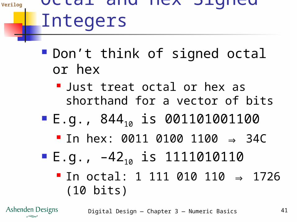
Octal and Hex Signed Integers Don’t think of signed octal or hex
Just treat octal or hex as shorthand for a vector of bits
E.g., 84410 is 001101001100 In hex: 0011 0100 1100 ⇒ 34C
E.g., –4210 is 1111010110 In octal: 1 111 010 110 ⇒ 1726 (10
bits)
Verilog
Digital Design — Chapter 3 — Numeric Basics 42
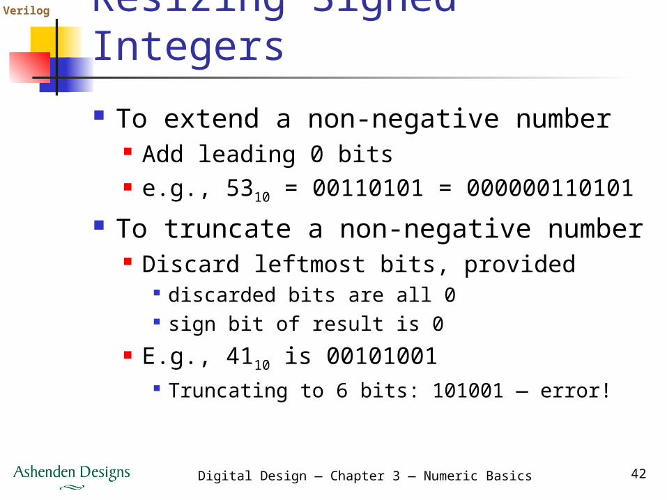
Resizing Signed Integers To extend a non-negative number
Add leading 0 bits e.g., 5310 = 00110101 = 000000110101
To truncate a non-negative number Discard leftmost bits, provided
discarded bits are all 0 sign bit of result is 0
E.g., 4110 is 00101001 Truncating to 6 bits: 101001 — error!
Verilog
Digital Design — Chapter 3 — Numeric Basics 43
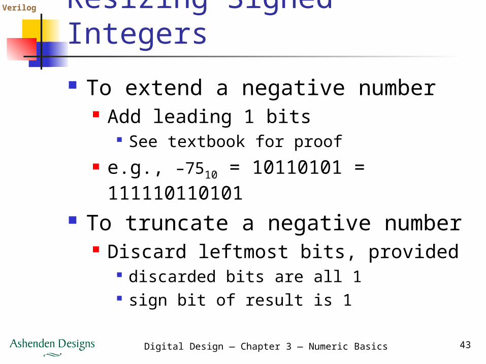
Resizing Signed Integers To extend a negative number
Add leading 1 bits See textbook for proof
e.g., –7510 = 10110101 = 111110110101
To truncate a negative number Discard leftmost bits, provided
discarded bits are all 1 sign bit of result is 1
Verilog
Digital Design — Chapter 3 — Numeric Basics 44
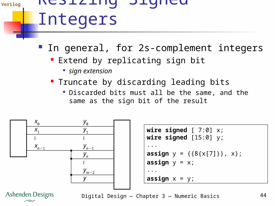
Resizing Signed Integers In general, for 2s-complement integers
Extend by replicating sign bit sign extension
Truncate by discarding leading bits Discarded bits must all be the same, and the
same as the sign bit of the result
wire signed [ 7:0] x;wire signed [15:0] y;...assign y = {{8{x[7]}}, x};assign y = x;...assign x = y;
… ……
x0
x1
xn − 1
y0
y1
yn − 1
yn
ym − 2
y
Verilog
Digital Design — Chapter 3 — Numeric Basics 45
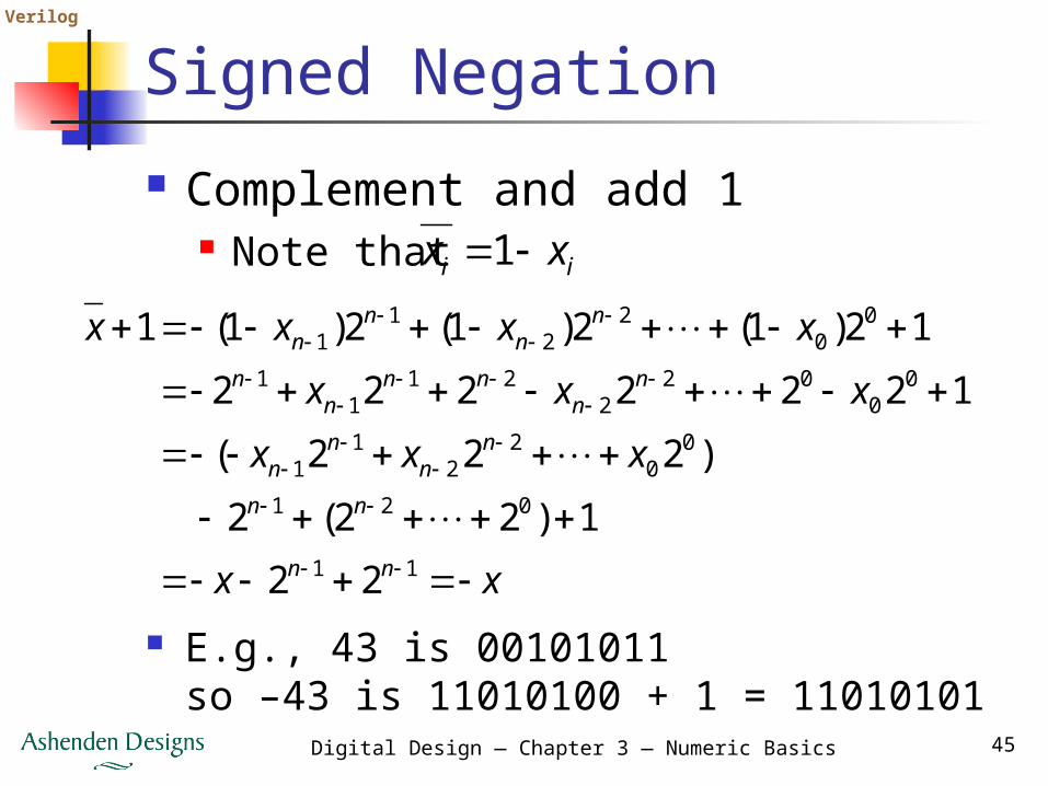
Signed Negation Complement and add 1
Note that
xx
xxx
xxx
xxxx
nn
nn
nn
nn
nn
nnn
n
nn
nn
11
021
00
22
11
00
022
211
1
00
22
11
22
1)22(2
)222(
1222222
12)1(2)1(2)1(1
ii xx 1
E.g., 43 is 00101011so –43 is 11010100 + 1 = 11010101
Verilog
Digital Design — Chapter 3 — Numeric Basics 46
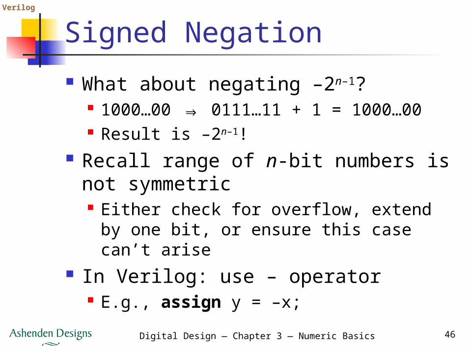
Signed Negation What about negating –2n–1?
1000…00 ⇒ 0111…11 + 1 = 1000…00 Result is –2n–1!
Recall range of n-bit numbers is not symmetric Either check for overflow, extend by
one bit, or ensure this case can’t arise In Verilog: use – operator
E.g., assign y = –x;
Verilog
Digital Design — Chapter 3 — Numeric Basics 47
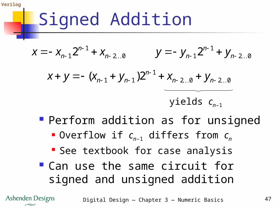
Signed Addition
Perform addition as for unsigned Overflow if cn–1 differs from cn
See textbook for case analysis Can use the same circuit for signed
and unsigned addition
021
12
nn
n xxx 021
12
nn
n yyy
02021
11 2)(
nnn
nn yxyxyx
yields cn–1
Verilog
Digital Design — Chapter 3 — Numeric Basics 48
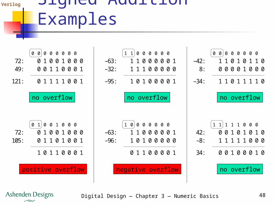
Signed Addition Examples
no overflow
positive overflow negative overflow
no overflow no overflow
no overflow
0 1 0 0 1 0 0 0
0 1 1 1 1 0 0 1
072:49:
121:
0 1 1 0 0 0 1
0 0 0 0 0 0 0 0
0 1 0 0 1 0 0 0
1 0 1 1 0 0 0 1
072:
105: 1 1 0 1 0 0 1
0 1 0 0 1 0 0 0
1 1 0 0 0 0 0 1
1 0 1 0 0 0 0 1
1–63:–32:
–95:
1 1 0 0 0 0 0
1 1 0 0 0 0 0 0
1 1 0 0 0 0 0 1
0 1 1 0 0 0 0 1
1–63:–96: 0 1 0 0 0 0 0
1 0 0 0 0 0 0 0
1 1 0 1 0 1 1 0
1 1 0 1 1 1 1 0
0–42:
–34:
8: 0 0 0 1 0 0 0
0 0 0 0 0 0 0 0
0 0 1 0 1 0 1 0
0 0 1 0 0 0 1 0
142:
34:
–8: 1 1 1 1 0 0 0
1 1 1 1 1 0 0 0
Verilog
Digital Design — Chapter 3 — Numeric Basics 49
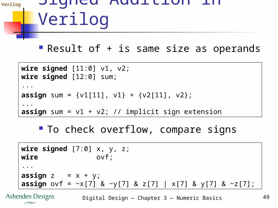
Signed Addition in Verilog Result of + is same size as operands
wire signed [11:0] v1, v2;wire signed [12:0] sum;...assign sum = {v1[11], v1} + {v2[11], v2};...assign sum = v1 + v2; // implicit sign extension
To check overflow, compare signswire signed [7:0] x, y, z;wire ovf;...assign z = x + y;assign ovf = ~x[7] & ~y[7] & z[7] | x[7] & y[7] & ~z[7];
Verilog
Digital Design — Chapter 3 — Numeric Basics 50
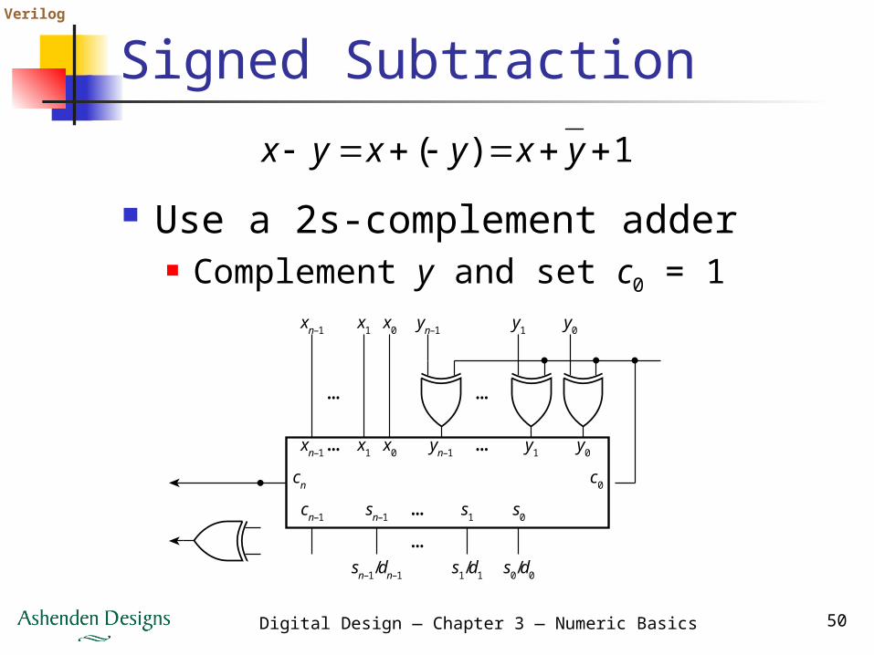
Signed Subtraction
Use a 2s-complement adder Complement y and set c0 = 1
1)( yxyxyx
y0y1yn–1
y0
c0cn
y1yn–1
…
…
…
…
x0x1xn–1
x0x1xn–1
… s0s1sn–1
sn–1/dn–1 s1/d1 s0/d0
…cn–1
Verilog
Digital Design — Chapter 3 — Numeric Basics 51
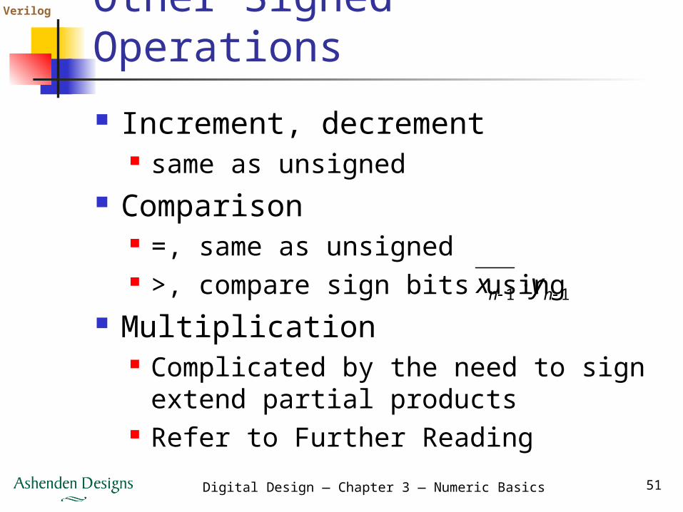
Other Signed Operations Increment, decrement
same as unsigned Comparison
=, same as unsigned >, compare sign bits using
Multiplication Complicated by the need to sign
extend partial products Refer to Further Reading
11 nn yx
Verilog
Digital Design — Chapter 3 — Numeric Basics 52
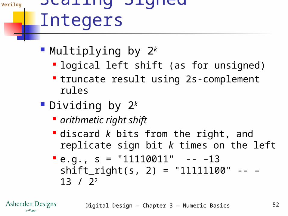
Scaling Signed Integers Multiplying by 2k
logical left shift (as for unsigned) truncate result using 2s-complement
rules Dividing by 2k
arithmetic right shift discard k bits from the right, and
replicate sign bit k times on the left e.g., s = "11110011" -- –13
shift_right(s, 2) = "11111100" -- –13 / 22
Verilog
Digital Design — Chapter 3 — Numeric Basics 53
Fixed-Point Numbers Many applications use non-integers
especially signal-processing apps Fixed-point numbers
allow for fractional parts represented as integers that are
implicitly scaled by a power of 2 can be unsigned or signed
Verilog
Digital Design — Chapter 3 — Numeric Basics 54
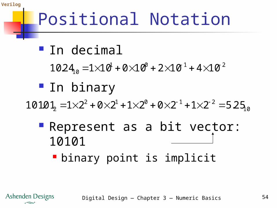
Positional Notation In decimal
210110 10410210010124.10
In binary10
210122 25.5212021202101.101
Represent as a bit vector: 10101 binary point is implicit
Verilog
Digital Design — Chapter 3 — Numeric Basics 55
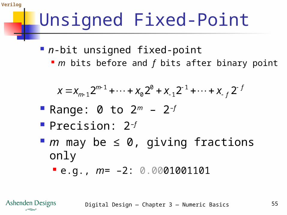
Unsigned Fixed-Point n-bit unsigned fixed-point
m bits before and f bits after binary pointf
fm
m xxxxx
2222 1
10
01
1
Range: 0 to 2m – 2–f
Precision: 2–f
m may be ≤ 0, giving fractions only e.g., m= –2: 0.0001001101

Verilog
Digital Design — Chapter 3 — Numeric Basics 56
Signed Fixed-Point n-bit signed 2s-complement fixed-point
m bits before and f bits after binary pointf
fm
m xxxxx
2222 1
10
01
1
Range: –2m–1 to 2m–1 – 2–f
Precision: 2–f
E.g., 111101, signed fixed-point, m = 2 11.11012 = –2 + 1 + 0.5 + 0.25 + 0.0625
= –0.187510
Verilog
Digital Design — Chapter 3 — Numeric Basics 57
Choosing Range and Precision Choice depends on application Need to understand the numerical
behavior of computations performed some operations can magnify quantization
errors In DSP
fixed-point range affects dynamic range precision affects signal-to-noise ratio
Perform simulations to evaluate effects
Verilog
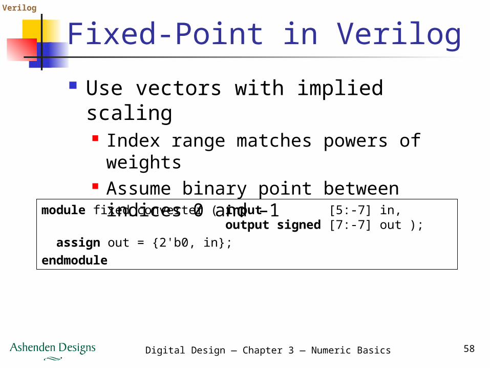
Digital Design — Chapter 3 — Numeric Basics 58
Fixed-Point in Verilog Use vectors with implied scaling
Index range matches powers of weights
Assume binary point between indices 0 and –1
module fixed_converter ( input [5:-7] in, output signed [7:-7] out ); assign out = {2'b0, in};endmodule
Verilog
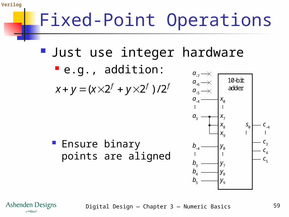
Digital Design — Chapter 3 — Numeric Basics 59
Fixed-Point Operations Just use integer hardware
e.g., addition:fff yxyx 2/)22(
Ensure binary points are aligned
x0
10-bitadder
……a–4
a–5
a–6
a–7
x7a3
x8
x9
y0……
b–4
y7b3
b4
b5
c–4
c3
c4
c5
…
y8
y9
s0…
Verilog
Digital Design — Chapter 3 — Numeric Basics 60
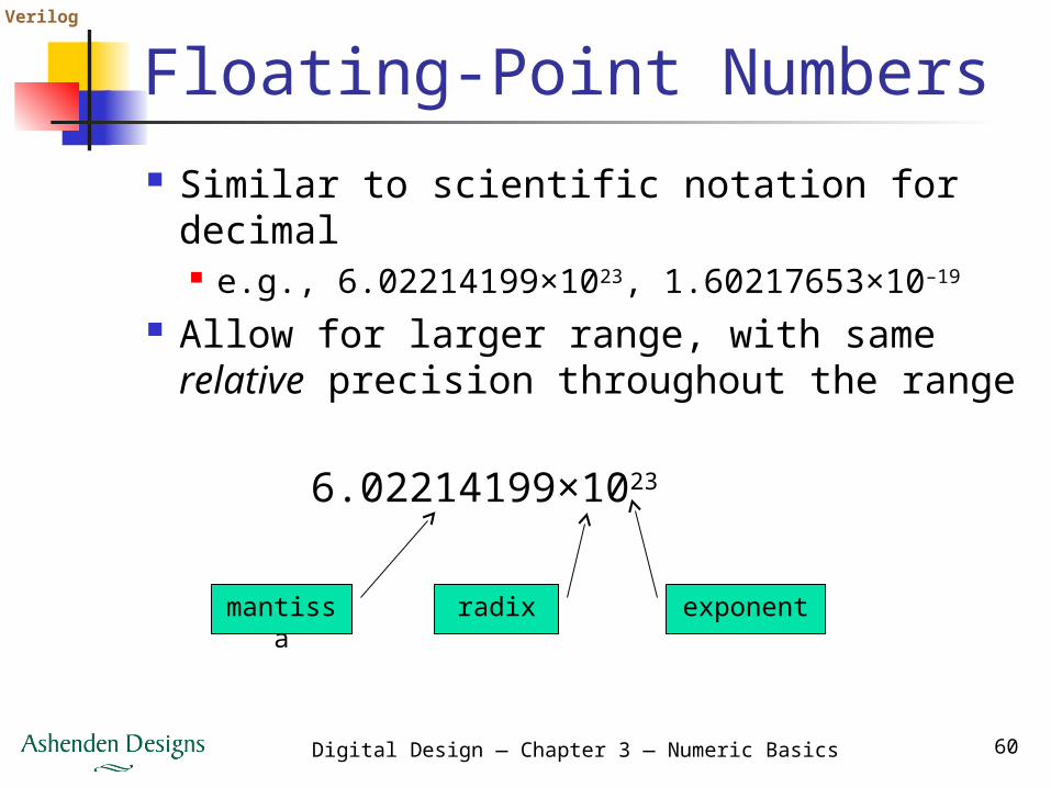
Floating-Point Numbers Similar to scientific notation for decimal
e.g., 6.02214199×10²³, 1.60217653×10⁻¹⁹
Allow for larger range, with same relative precision throughout the range
6.02214199×10²³
mantissa radix exponent
Verilog
Digital Design — Chapter 3 — Numeric Basics 61
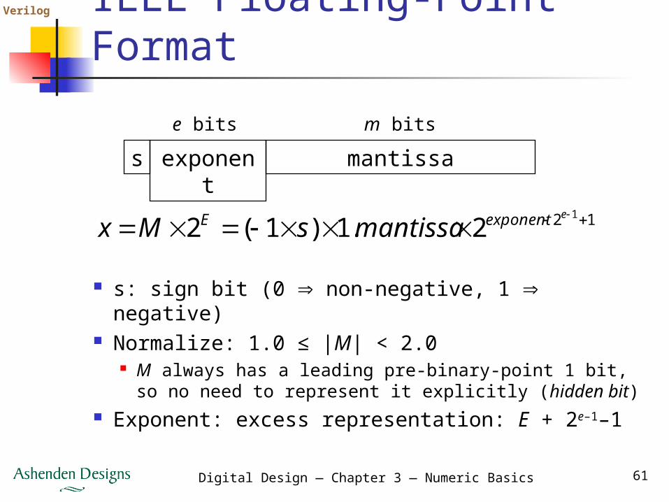
IEEE Floating-Point Format
s: sign bit (0 non-negative, 1 negative) Normalize: 1.0 ≤ |M| < 2.0
M always has a leading pre-binary-point 1 bit, so no need to represent it explicitly (hidden bit)
Exponent: excess representation: E + 2e–1–1
s exponent
mantissae bits m bits
12 1
2.1)1(2
eexponentE mantissasMx
Verilog
Digital Design — Chapter 3 — Numeric Basics 62
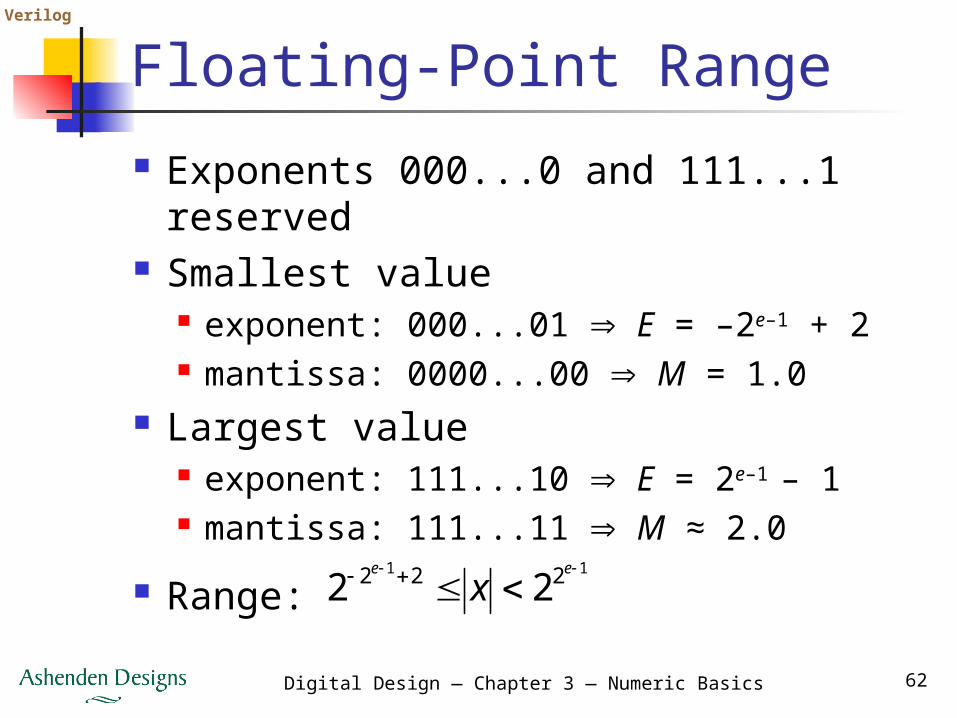
Floating-Point Range Exponents 000...0 and 111...1
reserved Smallest value
exponent: 000...01 E = –2e–1 + 2 mantissa: 0000...00 M = 1.0
Largest value exponent: 111...10 E = 2e–1 – 1 mantissa: 111...11 M ≈ 2.0
Range:11 222 22
ee
x
Verilog
Digital Design — Chapter 3 — Numeric Basics 63
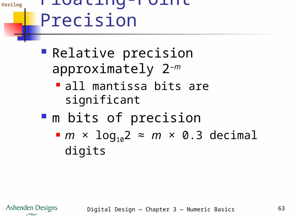
Floating-Point Precision Relative precision approximately 2–
m
all mantissa bits are significant m bits of precision
m × log102 ≈ m × 0.3 decimal digits
Verilog
Digital Design — Chapter 3 — Numeric Basics 64
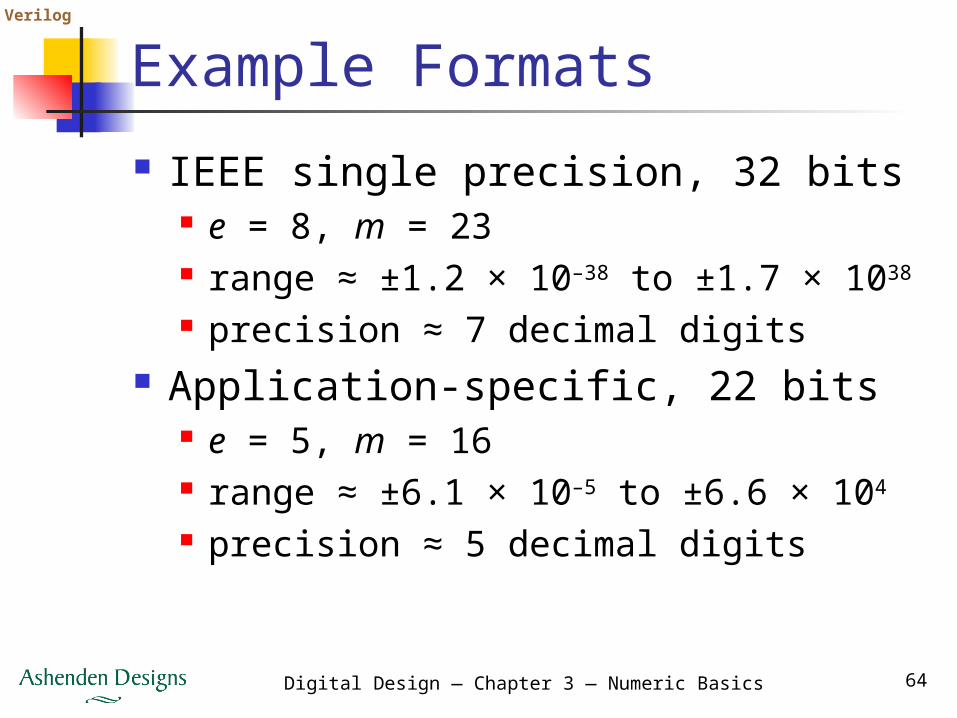
Example Formats IEEE single precision, 32 bits
e = 8, m = 23 range ≈ ±1.2 × 10–38 to ±1.7 × 1038
precision ≈ 7 decimal digits Application-specific, 22 bits
e = 5, m = 16 range ≈ ±6.1 × 10⁻⁵ to ±6.6 × 10⁴
precision ≈ 5 decimal digits
Verilog
Digital Design — Chapter 3 — Numeric Basics 65
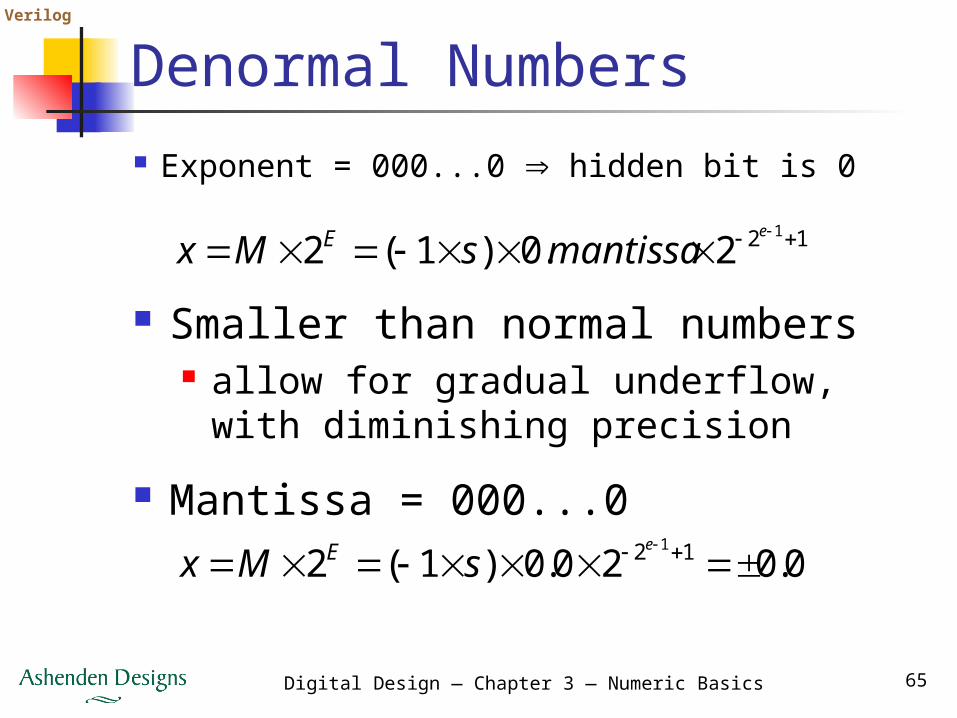
Denormal Numbers Exponent = 000...0 hidden bit is 0
12 1
2.0)1(2
e
mantissasMx E
Smaller than normal numbers allow for gradual underflow, with
diminishing precision Mantissa = 000...0
0.020.0)1(2 12 1
e
sMx E

Verilog
Digital Design — Chapter 3 — Numeric Basics 66
Infinities and NaNs Exponent = 111...1, mantissa = 000...0
±Infinity Can be used in subsequent calculations,
avoiding need for overflow check Exponent = 111...1, mantissa ≠ 000...0
Not-a-Number (NaN) Indicates illegal or undefined result
e.g., 0.0 / 0.0 Can be used in subsequent calculations
Verilog
Digital Design — Chapter 3 — Numeric Basics 67
Floating-Point Operations Considerably more complicated
than integer operations E.g., addition
unpack, align binary points, adjust exponents
add mantissas, check for exceptions round and normalize result, adjust
exponent Combinational circuits not feasible
Pipelined sequential circuits
Verilog
Digital Design — Chapter 3 — Numeric Basics 68
Summary Unsigned: Signed: Octal and Hex short-hand Operations: resize, arithmetic,
compare Arithmetic circuits trade off
speed/area/power Fixed- and floating-point non-integers Gray codes for position encoding
00
22
11 222 xxxx n
nn
n
00
22
11 222 xxxx n
nn
n