


Idiomas
Páginas
Jurídico

1P/N 134897500B (0904) www.frigidaire.com
SUBJECT PAGEPre-Installation Requirements...............................2Electrical Requirements..........................................3Water Supply Requirements ....................................3Drain Requirements.................................................3Exhaust System Requirements .................................4-5Gas Supply Requirements ...........................................5Location...................................................................5Rough-ln Dimensions.............................................6Mobile Home Installation...........................................7Unpacking..............................................................7Electrical Installation.................................................8Grounding Requirements.........................................83 & 4-Wire Connections ............................................9Installation.......................................................10-11Replacement Parts.................................................11
Table Of Contents
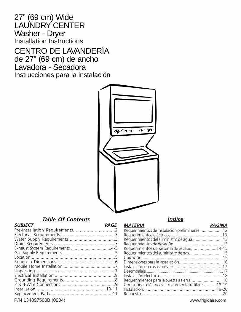
27” (69 cm) WideLAUNDRY CENTERWasher - DryerInstallation InstructionsCENTRO DE LAVANDERÍAde 27" (69 cm) de anchoLavadora - Secadora Instrucciones para la instalación
IndiceMATERIA PAGINARequerimientos de instalación preliminares....................12Requerimientos eléctricos...........................................13Requerimientos del suministro de agua..........................13Requerimientos de desagüe..........................................13Requerimientos del sistema de escape.....................14-15Requerimientos del suministro de gas.............................15Ubicación.......................................................................15Dimensiones para la instalación.....................................16Instalación en casas móviles........................................17Desembalaje........................................................................17Instalación eléctrica.....................................................18Requerimientos para la puesta a tierra...........................18Conexiónes eléctricas - trifilares y tetrafilares..........18-19Instalación..............................................................19-20Repuestos...................................................................20
2
IMPORTANT SAFETY INSTRUCTION
This is the safety alert symbol. This symbol alerts you to hazards that can kill or hurt you or others. All safety messages willbe preceded by the safety alert symbol and the word "DANGER" or "WARNING". These words mean:
DANGER
All safety messages will identify the hazard, tell you how to reduce the chance of injury, and tell you what can happen if theinstructions are not followed.
For your safety the information in this manual must be followed to minimize the risk of fire orexplosion or to prevent property damage, personal injury or loss of life. Do not store or use gasoline or other flammable vaporsand liquid in the vicinity of this or any other appliance.
Read all of the following instructions before installing and using this appliance.• Destroy the carton and plastic bags after the Laundry Center is unpacked. Children might use them for play. Cartons
covered with rugs, bedspreads, or plasic sheets can become airtight chambers causing suffocation. Place all materials in a garbage container or make materials inaccessible to children.• Installations must be performed by a qualified or licensed contractor, plumber, or gasfitter qualified or license by the state,
province, or region where this appliance is being installed.• Before beginning installation, carefully read these instructions. This will simplify the installation and ensure the Laundry Center
is installed correctly and safely. Leave these instructions near the Laundry Center after installation for future reference.• The electrical service to the Laundry Center must conform with local codes and ordinances and the latest edition of the National
Electrical Code, ANSI/NFPA 70, or in Canada, the Canadian electrical code C22.1 part 1.• The gas service to the Laundry Center must conform with local codes and ordinances and the latest edition of the National Fuel
Gas Code ANSI Z223.1, or in Canada, CAN/ACG B149.1-2000.• The Laundry Center is designed under ANSI Z 21.5.1 or ANZI/UL 2158 - CAN/CSA C22.2 No. 112 (latest editions) for HOME
USE only. This Laundry Center is not recommended for commercial applications such as restaurants or beauty salons, etc.• Do not install a Laundry Center with flexible plastic venting materials. Flexible venting materials are known to collapse, be
easily crushed and trap lint. These conditions will obstruct clothes dryer airflow and increase the risk of fire.• Your safety and the safety of others is very important. We have provided many important safety messages in the
Installation Instructions / Use & Care Guide and on your appliance. Always read and obey all safety messages.• The instructions in this manual and other literature included with this dryer are not meant to cover every possible condition and
situation that may occur. Good safe practice and caution MUST be applied when installing, operating and maintaing any appliance.
WHAT TO DO IF YOU SMELL GAS• Do not try to light any appliance.• Do not touch any electrical switch; do not use any phone in your building.• Clear the room, building or area of all occupants.• Immediately call your gas supplier from a neighbor’s phone. Follow the gas supplier's instructions.• If you cannot reach your gas supplier, call the fire department.
You can be killed or seriously injured if you don't immediately follow instructions.
You can be killed or seriously injured if you don't follow instructions.
PRE-INSTALLATION REQUIREMENTS
Tools and Materials Required for Installation: • Adjustable pliers. • Phillips, straight, & square bit screwdrivers. • Adjustible wrench. • Pipe wrench for gas supply (gas dryer). • LP-resistant thread tape (for natural gas or LP supply, gas dryer)
• Carpenter's level. • External vent hood. • Rigid or semi-rigid metal 4 inch (10.2 cm) exhaust duct work. • 3-wire or 4-wire 240 volt corg kit (electric dryer).
• 4 in. (10.2 cm) clamp. • Gas line shutoff valve (gas dryer). • ½ NPT union flare adapters (x2) and flexible gas supply line (gas dryer). • Metal foil tape not (duct tape).
3
ELECTRICAL REQUIREMENTS
ELECTRIC Laundry Center
CIRCUIT - Individual 30 amp. branch circuit fused with 30amp. time delay fuses or circuit breakers.
Use separately fused circuits for washers and dryers, and DONOT operate a washer and a dryer on the same circuit.
POWER SUPPLY - 3 wire or 4-wire, 240 volt, single phase, 60Hz, Alternating Current.
POWER SUPPLY CORD KIT - 3 wire - the dryer MUST employa 3-conductor power supply cord NEMA 10-30 type SRDT ratedat 240 volt AC minimum, 30 amp., with 3 open end spade lugconnectors with upturned ends or closed loop connectors andmarked for use with clothes dryers. See ELECTRICALCONNECTIONS FOR A 3-WIRE SYSTEM.
4 wire - The dryer MUST employ a 4-conductor power supplycord NEMA 14-30 type SRDT or ST (as required) rated at 240volt AC minimum, 30 amp., with 4 open end spade lugconnectors with upturned ends or closed loop connectors andmarked for use with clothes dryers. See ELECTRICALCONNECTIONS FOR A 4-WIRE SYSTEM.(Canada - 4-wire power supply cord is installed on dryer.)
WARNING – Risk of Shock. Appliance grounded to neutralconductor through a link. Grounding through the neutral link isprohibited for (1) New branch circuit installations (2) mobilehomes; (3) recreational vehicles; and (4) areas where local codesdo not permit grounding through the neutral, (1) disconnect thelink from the neutral, (2) use grounding terminal or lead toground appliance in accordance with local codes and (3) connectneutral terminal or lead to branch circuit neutral in usual manner(if the appliance is to be connected by means of a cord kit, use4-conductor cord for this purpose). USE COPPER CONDUCTORONLY.
OUTLET RECEPTACLE - NEMA 10-30R receptacle to be locatedso the power supply cord is accessible when the dryer is in theinstalled position. (Canada - NEMA 14-30R receptacle.)
WATER SUPPLY REQUIREMENTS
Hot and cold water faucets MUST be installed within 42 inches(106.68 cm) of your laundry center’s water inlet. The faucetsMUST be 3/4 inch (1.9 cm) garden hose type so inlet hoses canbe connected. Water pressure MUST be between 10 and 120pounds per square inch (maximum unbalance pressure, hot vs.cold, 10 psi). Your water department can advise you of yourwater pressure.
CIRCUIT - Individual 15 amp minimum branch circuit fused witha time delay fuse or circuit breaker.
POWER SUPPLY -3 wire, 120 volt single phase, 60 Hz,Alternating Current.
POWER SUPPLY CORD -The gas laundry center is equippedwith a 120 volt 3-wire power cord.
GAS Laundry Center
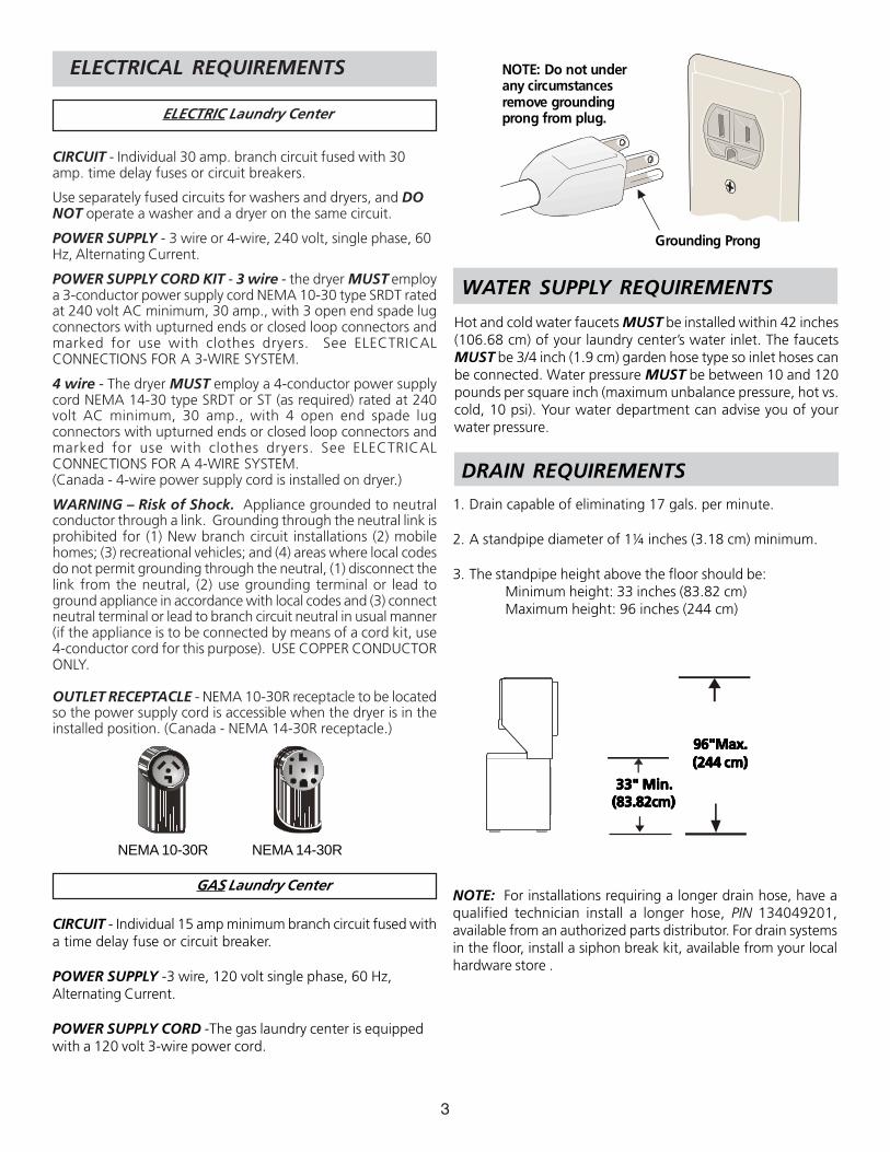
NEMA 10-30R NEMA 14-30R
NOTE: Do not underany circumstancesremove groundingprong from plug.
Grounding Prong
DRAIN REQUIREMENTS
1. Drain capable of eliminating 17 gals. per minute.
2. A standpipe diameter of 1¼ inches (3.18 cm) minimum.
3. The standpipe height above the floor should be:Minimum height: 33 inches (83.82 cm)Maximum height: 96 inches (244 cm)
33" Min.33" Min.33" Min.33" Min.33" Min.(83.82cm)(83.82cm)(83.82cm)(83.82cm)(83.82cm)
NOTE: For installations requiring a longer drain hose, have aqualified technician install a longer hose, PIN 134049201,available from an authorized parts distributor. For drain systemsin the floor, install a siphon break kit, available from your localhardware store .
96"Max.96"Max.96"Max.96"Max.96"Max.(244 cm)(244 cm)(244 cm)(244 cm)(244 cm)
4
Do not allow combustible materials (forexample: clothing, draperies/curtains, paper) to come incontact with exhaust system. The dryer MUST NOT beexhausted into a chimney, a wall, a ceiling, or any concealedspace of a building which can accumulate lint, resulting in a firehazard.
Exceeding the length of duct pipe or numberof elbows allowed in the "MAXIMUM LENGTH" charts cancause an accumulation of lint in the exhaust system. Pluggingthe system could create a fire hazard, as well as increase dryingtimes.
Do not screen the exhaust ends of the ventsystem, nor use any screws, rivets or other fastening meansthat extend into the duct and catch lint to assemble theexhaust system. Lint can become caught in the screen, on thescrews or rivets, clogging the duct work and creating a fire hazardas well as increasing drying times. Use an approved vent hoodto terminate the duct outdoors, and seal all joints with ducttape. All male duct pipe fittings MUST be installed downstreamwith the flow of air.
Explosion hazard. Do not install the dryerwhere gasoline or other flammables are kept or stored. Ifthe dryer is installed in a garage, it must be a minimum of 18inches (45.7 cm) above the floor. Failure to do so can result indeath, explosion, fire or burns. The exhaust system back pressureMUST not exceed 0.6 inches (1.52 cm) of water column,measured with an inclined manometer at the point the exhaustconnects to the dryer. The exhaust system should be inspectedand cleaned a minimum of every 18 months with normalusage. The more the dryer is used, the more often you shouldcheck the exhaust system and vent hood for proper operation.
The maximum length of the exhaust system depends upon thetype of duct used, number of elbows and type of exhaust hood.
The maximum length for both rigid and flexible duct is shown inthe chart below.
Do not install flexible plastic or flexible foil ventingmaterial. If installing semi-rigid venting, do not exceed 8 ft.(2.4m) duct length.
CORRECT CORRECT
INCORRECT INCORRECT
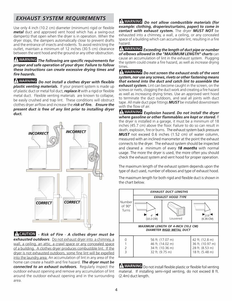
EXHAUST SYSTEM REQUIREMENTS
Use only 4 inch (10.2 cm) diameter (minimum) rigid or flexiblemetal duct and approved vent hood which has a swing-outdamper(s) that open when the dryer is in operation. When thedryer stops, the dampers automatically close to prevent draftsand the entrance of insects and rodents. To avoid restricting theoutlet, maintain a minimum of 12 inches (30.5 cm) clearancebetween the vent hood and the ground or any other obstruction.
The following are specific requirements forproper and safe operation of your dryer. Failure to followthese instructions can create excessive drying times andfire hazards.
Do not install a clothes dryer with flexibleplastic venting materials. If your present system is made upof plastic duct or metal foil duct, replace it with a rigid or flexiblemetal duct. Flexible venting materials are known to collapse,be easily crushed and trap lint. These conditions will obstructclothes dryer airflow and increase the risk of fire. Ensure thepresent duct is free of any lint prior to installing dryerduct.
- Risk of Fire - A clothes dryer must beexhausted outdoors. Do not exhaust dryer into a chimney, awall, a ceiling, an attic, a crawl space or any concealed spaceof a building. A clothes dryer produces combustible lint. If thedryer is not exhausted outdoors, some fine lint will be expelledinto the laundry area. An accumulation of lint in any area of thehome can create a health and fire hazard. The dryer must beconnected to an exhaust outdoors. Regularly inspect theoutdoor exhaust opening and remove any accumulation of lintaround the outdoor exhaust opening and in the surroundingarea.
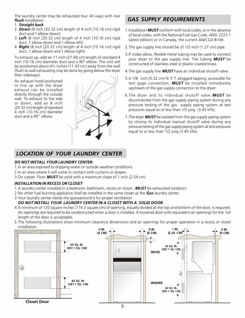
EXHAUST DUCT LENGTHS
Numberof 90°Turns
MAXIMUM LENGTH OF 4-INCH (10.2 CM)DIAMETER RIGID METAL DUCT
EXHAUST HOOD TYPE
0123
56 ft. (17.07 m)46 ft. (14.02 m)34 ft. (10.36 m)32 ft. (9.75 m)
42 ft. (12.8 m)36 ft. (10.97 m)28 ft. (8.53 m)18 ft. (5.48 m)
Louvered4”
(10.2 CM)2.5”
(6.35 CM)
5
60 SQ. IN.(387.1 SQ. CM)
60 SQ. IN.(387.1 SQ. CM)
Closet Door
0 IN.(0 CM)
DRYER
WASHER
0 IN.(0 CM)
1 IN.(2.54 CM)
0 IN.(0 CM)
60 SQ. IN.(387.1 SQ. CM)
60 SQ. IN.(387.1 SQ. CM)
LOCATION OF YOUR LAUNDRY CENTERDO NOT INSTALL YOUR LAUNDRY CENTER:1.In an area exposed to dripping water or outside weather conditions.2.In an area where it will come in contact with curtains or drapes.3.On carpet. Floor MUST be solid with a maximum slope of 1 inch (2.54 cm).
INSTALLATION IN RECESS OR CLOSET1.A laundry center installed in a bedroom, bathroom, recess or closet, MUST be exhausted outdoors.2.No other fuel burning appliance shall be installed in the same closet as the Gas laundry center.3.Your laundry center needs the spacearound it for proper ventilation.
DO NOT INSTALL YOUR LAUNDRY CENTER IN A CLOSET WITH A SOLID DOOR.4.A minimum of 120 square inches (774.2 square cm) of opening, equally divided at the top and bottom of the door, is required.
Air openings are required to be unobstructed when a door is installed. A louvered door with equivalent air openings for the fulllength of the door is acceptable.
5.The following illustrations show minimum clearance dimensions and air openings for proper operation in a recess or closetinstallation.
The laundry center may be exhausted four (4) ways with rearflush installation:1. Straight back2. Down (8 inch [20.32 cm] length of 4 inch [10.16 cm] rigid
duct and 1 elbow down)3. Left (8 inch [20.32 cm] length of 4 inch [10.16 cm] rigid
duct, 1 elbow down and 1 elbow left)4. Right (8 inch [20.32 cm] length of 4 inch [10.16 cm] rigid
duct, 1 elbow down and 1 elbow right)
To exhaust up, add an 11 inch (27.94 cm) length of standard 4inch (10.16 cm) diameter duct and a 90° elbow. The unit willbe positioned about 4½ inches (11.43 cm) away from the wall(flush to wall exhausting may be done by going below the dryerthen sideways).
An exhaust hood positionedto line up with the dryerexhaust can be installeddirectly through the outsidewall. To exhaust to the sideor down, add an 8 inch(20.32 cm) length of standard4 inch (10.16 cm) diameterduct and a 90° elbow.
GAS SUPPLY REQUIREMENTS
1.Installation MUST conform with local codes, or in the absenceof local codes, with the National Fuel Gas Code, ANSI Z223.1(latest edition) or in Canada, the current AN/CGA B149.
2.The gas supply line should be of 1/2 inch (1.27 cm) pipe.
3.If codes allow, flexible metal tubing may be used to connectyour dryer to the gas supply line. The tubing MUST beconstructed of stainless steel or plastic-coated brass.
4.The gas supply line MUST have an individual shutoff valve.
5.A 1/8 inch (0.32 cm) N. P. T. plugged tapping, accessible fortest gage connection, MUST be installed immediatelyupstream of the gas supply connection to the dryer.
6.The dryer and its individual shutoff valve MUST bedisconnected from the gas supply piping system during anypressure testing of the gas supply piping system at testpressures equal to or less than 1/2 psig (3.45 kPa).
7.The dryer MUST be isolated from the gas supply piping systemby closing its individual manual shutoff valve during anypressure testing of the gas supply piping system at test pressuresequal to or less than 1/2 psig (3.45 kPa).
6
25 ¼
IN.
(64.
13 C
M)
4 13
/16
IN.
(12.
22 C
M)
2 ½
IN.
(6.3
5 C
M)
47“
16 ¼
IN.
(41.
27 C
M)
36 1
/16I
N.
(91.
60 C
M)
30 1
3/16
IN.
(78.
26 C
M)
11 7
/16
IN.
(29.
5 CM
)
1 7/
8 IN
.(4
.76
CM)
3 ¾
IN.
(9.5
2 C
M)
9 3/
8 IN
.(2
3.81
CM
)
41 ¼
IN(1
04.7
7 C
M)
29 7
/16
IN(7
4.77
CM
)
27 IN
.(6
8.58
CM
)
DR
AIN
OU
TLET
(REA
R)
WA
TER
INLE
TS(R
EAR
)
VEN
T
5 ¼
IN.
(13.
33 C
M)G
AS
SUPP
LYPI
PE (R
EAR
)
43 IN
.(1
09.2
2 C
M)
54 5
/16
IN.
(137
.95
CM
)
75 ½
IN.
(191
.77
CM
)
43 IN
.(1
09.2
2 C
M)
ELEC
TRIC
AL
CON
NEC
TIO
N
12
½ IN
.(3
1.75
CM
)
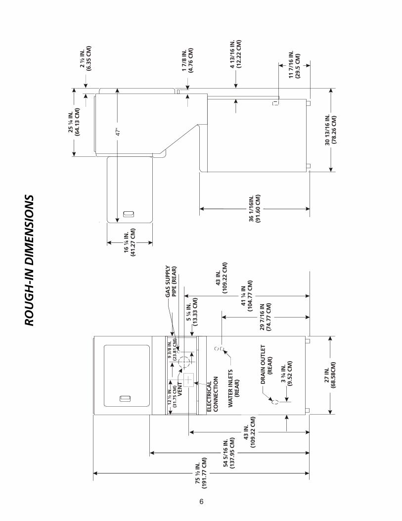
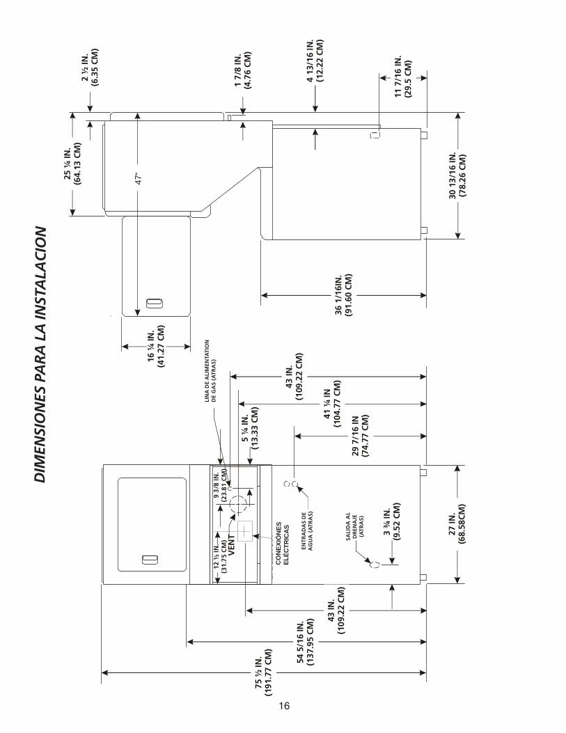
RO
UG
H-I
N D
IMEN
SIO
NS
7
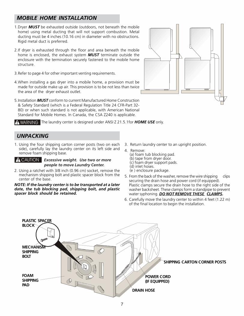
PLASTIC SPACERBLOCK
MECHANISMSHIPPINGBOLT
FOAMSHIPPINGPAD
DRAIN HOSE
POWER CORD(IF EQUIPPED)
SHIPPING CARTON CORNER POSTS
1. Using the four shipping carton corner posts (two on eachside), carefully lay the laundry center on its left side andremove foam shipping base.
CAUTION Excessive weight. Use two or more people to move Laundry Center.
2. Using a ratchet with 3/8 inch (0.96 cm) socket, remove themechanism shipping bolt and plastic spacer block from thecenter of the base.
NOTE: If the laundry center is to be transported at a laterdate, the tub blocking pad, shipping bolt, and plasticspacer block should be retained.
3. Return laundry center to an upright position.
4. Remove:(a) foam tub blocking pad.(b) tape from dryer door.(c) foam dryer support pads.(d) inlet hoses.(e ) enclosure package.
5. From the back of the washer, remove the wire shipping clipssecuring the drain hose and power cord (if equipped).Plastic clamps secure the drain hose to the right side of thewasher backsheet. These clamps form a standpipe to preventwater syphoning. DO NOT REMOVE THESE CLAMPS.
6. Carefully move the laundry center to within 4 feet (1.22 m)of the final location to begin the installation.
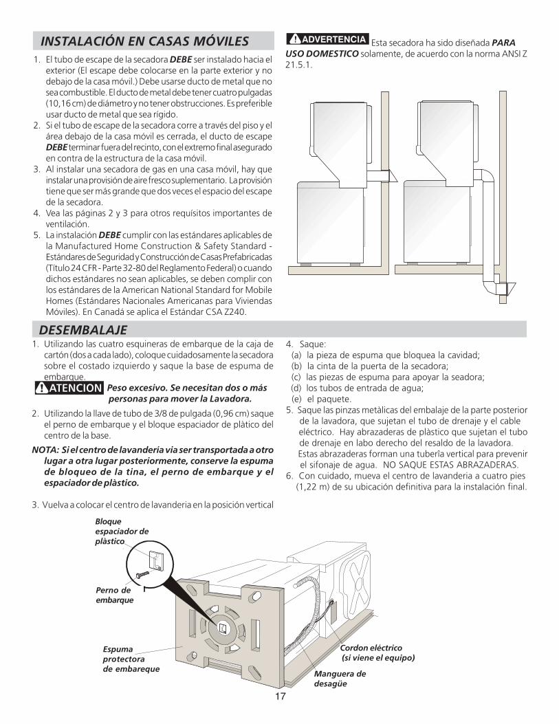
1.Dryer MUST be exhausted outside (outdoors, not beneath the mobilehome) using metal ducting that will not support combustion. Metalducting must be 4 inches (10.16 cm) in diameter with no obstructions.Rigid metal duct is preferred.
2.If dryer is exhausted through the floor and area beneath the mobilehome is enclosed, the exhaust system MUST terminate outside theenclosure with the termination securely fastened to the mobile homestructure.
3.Refer to page 4 for other important venting requirements.
4.When installing a gas dryer into a mobile home, a provision must bemade for outside make up air. This provision is to be not less than twicethe area of the dryer exhaust outlet.
5.Installation MUST conform to current Manufactured Home Construction& Safety Standard (which is a Federal Regulation Title 24 CFR-Part 32-80) or when such standard is not applicable, with American NationalStandard for Mobile Homes. In Canada, the CSA Z240 is applicable.
WARNING The laundry center is designed under ANSI Z 21.5.1for HOME USE only.
UNPACKING
MOBILE HOME INSTALLATION
8
ELECTRICAL INSTALLATION
The following are specific requirements forproper and safe electrical installation of your laundry center.Failure to follow these instructions can create electrical shockand/or a fire hazard.
This appliance MUST be properly grounded.Electrical shock can result if the laundry center is not properlygrounded. Follow the instructions in this manual for propergrounding.
Do not use an extension cord with thislaundry center. Some extension cords are not designed towithstand the amounts of electrical current this laundry centerutilizes and can melt, creating electrical shock and/or fire hazard.Locate the laundry center within reach of the receptacle for thelength power cord to be purchased, allowing some slack in thecord. Refer to the pre-installation requirements in this manualfor the proper power cord to be purchased.
A U.L. approved strain relief must beinstalled onto power cord. If the strain relief is not attached, thecord can be pulled out of the laundry center and can be cut byany movement of the cord, resulting in electrical shock.
Do not use an aluminum wired receptaclewith a copper Wired power cord and plug (or vice versa). Achemical reaction occurs between copper and aluminum andcan cause electrical shorts.
The proper wiring and receptacle is a copper wired powercord with a copper wired receptacle OR aluminum wiredpower cord with an aluminum wired receptacle.
NOTE: Laundry centers operating on a 208 volt power supplywill have longer drying times than laundry centers operating ona 240 volt power supply.
GROUNDING REQUIREMENTS
Improper connection of the equipmentgrounding conductor can result in a risk of electrical shock.Check with a licensed electrician if you are in doubt as to whetherthe appliance is properly grounded.
For a grounded, cord-connected laundry center:1. The laundry center MUST be grounded. In the event of
malfunction or breakdown, grounding will reduce the risk ofelectrical shock by a path of least resistance for electricalcurrent.
2. If your laundry center is equipped with a power supply cordhaving an equipment-grounding conductor and a groundingplug, the plug MUST be plugged into an appropriate, copperwired receptacle that is properly installed and grounded inaccordance with all local codes and ordinances. If in doubt,call a licensed electrician. Do not modify plug providedwith the appliance.
For a permanently connected laundry center:The laundry center MUST be connected to a grounded metal,permanent wiring system; or an equipment grounding conductorMUST be run with the circuit conductors and connected to theequipment-grounding terminal or lead on the appliance.
Improper connection of the equipmentgrounding conductor can result in a risk of electrical shock.Check with a licensed electrician if you are in doubt as towhether the appliance is properly grounded.
For a grounded cord connected laundry center:1. The laundry center MUST be grounded. In the event of
malfunction or breakdown, grounding will reduce the risk ofelectrical shock by providing a path of least resistance forthe electrical current.
2. Since your laundry center is equipped with a power supplycord having an equipment-grounding conductor and agrounding plug, the plug MUST be plugged into anappropriate outlet that is properly installed and grounded inaccordance with all codes and ordinances. If in doubt, call alicensed electrician.
1. The laundry center is equipped with a three-prong (grounding)plug for your protection against shock hazard and shouldbe plugged directly into a properly grounded three-prongreceptacle. Do not cut or remove the grounding prong fromthe plug.
Non-Canadian ELECTRIC Laundry Center
ALL GAS Laundry Centers
DANGER
DANGER
ALL ELECTRIC Laundry Centers
Canadian ELECTRIC Laundry Center
WARNING
WARNING
WARNING
WARNING
WARNING
9
NON-CANADIAN ELECTRIC Laundry Center
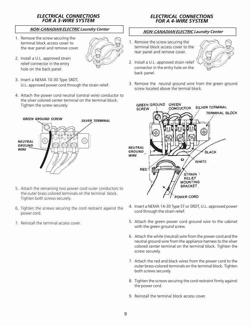
5. Attach the remaining two power cord outer conductors tothe outer brass colored terminals on the terminal block.Tighten both screws securely.
6. Tighten the screws securing the cord restraint against thepower cord.
7. Reinstall the terminal access cover.
SILVER TERMINALGREEN GROUND SCREW
NEUTRALGROUNDWIRE
ELECTRICAL CONNECTIONSFOR A 3-WIRE SYSTEM
1. Remove the screw securing theterminal block access cover tothe rear panel and remove cover.
2. Install a U.L. approved strainrelief connector in the entryhole on the back panel.
3. Insert a NEMA 10-30 Type SRDT,U.L. approved power cord through the strain relief.
4. Attach the power cord neutral (central wire) conductor tothe silver colored center terminal on the terminal block.Tighten the screw securely.
NON-CANADIAN ELECTRIC Laundry Center
NEUTRALGROUNDWIRE
1. Remove the screw securing theterminal block access cover to therear panel and remove cover.
2. Install a U.L. approved strain reliefconnector in the entry hole on theback panel.
3. Remove the neutral ground wire from the green groundscrew located above the termial block.
4. Insert a NEMA 14-30 Type ST or SRDT, U.L. approved powercord through the strain relief.
5. Attach the green power cord ground wire to the cabinetwith the green ground screw.
6. Attach the white (neutral) wire from the power cord and theneutral ground wire from the appliance harness to the silvercolored center terminal on the terminal block. Tighten thescrew securely.
7. Attach the red and black wires from the power cord to theouter brass-colored terminals on the terminal block. Tightenboth screws securely.
8. Tighten the screws securing the cord restraint firmly againstthe power cord.
9. Reinstall the terminal block access cover.
ELECTRICAL CONNECTIONSFOR A 4-WIRE SYSTEM
10
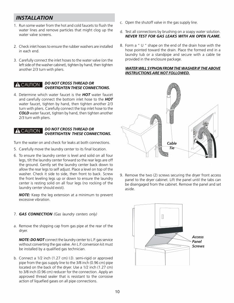
9. Remove the two (2) screws securing the dryer front accesspanel to the dryer cabinet. Lift the panel until the tabs canbe disengaged from the cabinet. Remove the panel and setaside.
AccessPanelScrews
CableTie
INSTALLATION1. Run some water from the hot and cold faucets to flush the
water lines and remove particles that might clog up thewater valve screens.
2. Check inlet hoses to ensure the rubber washers are installedin each end.
3. Carefully connect the inlet hoses to the water valve (on theleft side of the washer cabinet), tighten by hand, then tightenanother 2/3 turn with pliers.
DO NOT CROSS THREAD OR OVERTIGHTEN THESE CONNECTIONS.
4. Determine which water faucet is the HOT water faucetand carefully connect the bottom inlet hose to the HOTwater faucet, tighten by hand, then tighten another 2/3turn with pliers. Carefully connect the top inlet hose to theCOLD water faucet, tighten by hand, then tighten another2/3 turn with pliers.
DO NOT CROSS THREAD OR OVERTIGHTEN THESE CONNECTIONS.
Turn the water on and check for leaks at both connections.
5. Carefully move the laundry center to its final location.
6. To ensure the laundry center is level and solid on all fourlegs, tilt the laundry center forward so the rear legs are offthe ground. Gently set the laundry center back down toallow the rear legs to self adjust. Place a level on top of thewasher. Check it side to side, then front to back. Screwthe front leveling legs up or down to ensure the laundrycenter is resting solid on all four legs (no rocking of thelaundry center should exist).
NOTE: Keep the leg extension at a minimum to preventexcessive vibration.
7. GAS CONNECTION (Gas laundry centers only)
a. Remove the shipping cap from gas pipe at the rear of thedryer.
NOTE: DO NOT connect the laundry center to L.P. gas servicewithout converting the gas valve. An L.P. conversion kit mustbe installed by a qualified gas technician.
b. Connect a 1/2 inch (1.27 cm) I.D. semi-rigid or approvedpipe from the gas supply line to the 3/8 inch (0.96 cm) pipelocated on the back of the dryer. Use a 1/2 inch (1.27 cm)to 3/8 inch (0.96 cm) reducer for the connection. Apply anapproved thread sealer that is resistant to the corrosiveaction of liquefied gases on all pipe connections.
CAUTION
CAUTION
c. Open the shutoff valve in the gas supply line.
d. Test all connections by brushing on a soapy water solution.NEVER TEST FOR GAS LEAKS WITH AN OPEN FLAME.
8. Form a “ U “ shape on the end of the drain hose with thehose pointed toward the drain. Place the formed end in alaundry tub or a standpipe and secure with a cable tieprovided in the enclosure package.
WATER WILL SYPHON FROM THE WASHER IF THE ABOVEINSTRUCTIONS ARE NOT FOLLOWED.
11
10. Connect the exhaust duct to outside duct work. Use duct tape to seal all joints.
11. Plug the power cord into a grounded outlet.
12. Reinstall the dryer front access panel.
NOTE: Check to ensure the power is off at a circuit breaker/fuse box before plugging the power cord into anoutlet.
13. Turn on the power at a circuit breaker/fuse box.
14. Run the washer and dryer though a cycle. Check for properoperation.
NOTE: On gas dryers, before the burner will light, it isnecessary for the gas line to be bled of air. If the burnerdoes not light within 45 seconds the first time thedryer is turned on, the safety switch will shut theburner off. If this happens, turn the timer to “OFF”and wait 5 minutes before making another attempt tolight.
15. If your laundry center does not operate, please review the“Avoid Service Checklist” located in your Owner’s Guidebefore calling for service.
16. Place these instructions in a location near the laundrycenter for future reference.
NOTE: A wiring diagram is located behind the dryer frontaccess panel.
Before operating the dryer, makesure the dryer area is clear and free fromcombustible materials, gasoline, and otherflammable vapors. Also see that nothing (such asboxes, clothing, etc.) obstructs the flow ofcombustion and ventilation air.
WARNING
WARNING
REPLACEMENT PARTS
If replacement parts are needed for your laundry center, contactthe source where you purchased your laundry center.
Destroy the carton, plastic bags, and metalband after the laundry center is unpacked. Children might usethem for play. Cartons covered with rugs, bedspreads, or plasticsheets can become airtight chambers causing suffocation. Placeall materials in a garbage container or make materials inaccessibleto children.
Label all wires prior to disconnection whenservicing controls. Wiring errors can cause improper anddangerous operation. Verify proper operation after servicing.
The instructions in this manual and all otherliterature included with this laundry center are not meant tocover every possible condition and situation that may occur. Goodsafe practice and caution MUST be applied when installing,operating and maintaining any appliance.
Maximum benefits and enjoyment are achieved whenall the Safety and Operating instructions are understoodand practiced as a routine with your laundry tasks.
12
Este símbolo significa alerta. Este símbolo lo alerta acerca de peligros que pueden matar o lesionar, tanto a usted como aotras personas. Todos los mensajes de seguridad serán precedidos por el símbolo de alerta para su seguridad y la palabra "PELIGROo ADVERTENCIA" (DANGER” o WARNING). Estas palabras significan:
PELIGRO (DANGER) Usted morirá o resultará seriamente lesionado si no sigue las instrucciones siguientes.
ADVERTENCIA (WARNING) Usted puede morir o resultar seriamente lesionado si no sigue lasinstrucciones siguientes.
Todos los mensajes de seguridad identificarán el peligro, le dirán a usted cómo reducir la posibilidad de lesión ytambién qué puede suceder si no se siguen las instrucciones.
RIESGO DE INCENDIO. Para su seguridad, siga las instrucciones contenidas en este manual a fin de reducira un mínimo los riesgos de incendio o explosión o para evitar daños materiales, lesiones personales o la muerte. GUARDE ESTASINSTRUCCIONES.
• Hemos proporcionado muchos mensajes importantes para la seguridad en las Instrucciones de Operación del Manual de Uso yMantenimiento, las Instrucciones de Instalación y en el mismo aparato. Siempre lea y obedezca todos los mensajes paraseguridad.La instalación y el servicio de la centro de lavadaría de ropa se deben realizar por un instalador calificado, la agenciade servicio o el surtidor de gas.
• Instale la centro de lavadaría de ropa según las instrucciones del fabricante y los códigos locales. Antes de comenzar lainstalación, lea cuidadosamente estas instrucciones. Esto simplificará la instalación y asegurará que la secadora se instalecorrectamente y de manera segura. Después de completar la instalación, coloque estas instrucciones cerca de la secadora parareferencia futura.
• La alimentación eléctrica para la centro de lavadaría deberá cumplir con los códigos y reglamentos locales y con la última edición delCódigo Eléctrico Nacional, ANSI/NFPA 70 o en Canadá CSA C22.1 Código Eléctrico Canadiense, Parte 1.
• La alimentación de gas para la centro de lavadaría deberá cumplir con los códigos y reglamentos locales y con la última edición delCódigo Nacional para Gases Combustibles, ANSI Z223.1 o en Canadá CAN/CGA B149.12.
• La secadora está clasificada para USO DOMESTICO solamente, de acuerdo con la norma ANSI Z 21.5.1 o ANSI/UL 2158 - CAN/CSAC22.2 No. 112 (las últimas ediciónes). Esta secadora no se recomienda para uso commercial tal como en restaurantes, salones debelleza, etc.
• Los materiales de ventilación flexibles se pueden colapsar o apachurrar fácilmente y atrapar pelusa. Estas condiciones obstruirán lacirculación de aire de la centro de lavadaría de ropa y aumentarán el riesgo de incendio.
• No almacene ni utilice gasolina u otros vapores y líquidos inflamables en la proximidad de éste o de cualquier otro artefacto eléctrico.• La instalación y el servicio de mantenimiento debe de realizarlos un instalador calificado, la agencia de servicios o el proveedor de
gas.
QUE DEBE HACER SI PERCIBE OLOR A GAS• No trate de encender ningún artefacto eléctrico.• No toque ningún interruptor eléctrico; no use ningún teléfono en su edificio.• Haga salir a todos los ocupantes de la habitación, del edificio y del lugar.• Llame a su proveedor de gas desde el teléfono de un vecino. Siga las instrucciones del proveedor de gas.• Si no logra comunicarse con su proveedor de gas, llame al departamento de bomberos.
Requisitos de preinstalación
Herramientas y materiales necesarios para la instalación:• Pinzas ajustables• Destornilladores Philips con punta derecha y cuadrada• Llave ajustable• Llave para tubos de suministro de gas• Cinta aislante resistente al gas LP (para suministro de gas natural o LP)
• Nivel de carpintero• Capucha de ventilación externa• Conducto de escape de metal rígido o semirígido de 4 pulgadas (10 cm)• Kit de cables de alimentación trifilar o tetrafilar de 240 voltios (secadora eléctrica)• Abrazadera de 4” (10,2 cm)
• Válvula de cierre de línea de gas (secadora a gas)• Adaptadores NPI de unión acampanada (x2) y línea flexible de suministro de gas (secadora a gas) de ½’ (15,2 cm)• Cinta de papel aluminio (no cinta adhesiva aislante)
SEGURIDAD de CENTRO DE LAVANDARIA
13
NEMA 10-30RNEMA 10-30RNEMA 10-30RNEMA 10-30RNEMA 10-30R NEMA 14-30RNEMA 14-30RNEMA 14-30RNEMA 14-30RNEMA 14-30R
NOTA : Para las instalaciones que requieran un tubo de màslargo, pida a un técnico capacitado que instale un tubo màslargo, P/N 131461201, disponsible en los disribuidoresautorizados de piezas de repuesto. Para los sistemas de drenajeen el piso, instale un uego para detener la acción de sifón,disponsible de una ferretería local.
REQUERIMIENTOS ELÉCTRICOS
Centro de lavanderia ELÉCTRICAS
CIRCUITO: circuito independiente individual de 30 A con fusiblesde acción retardada o disyuntores.
Use circuitos con fusibles separados para las lavadoras ysecadoras y NO haga funcionar una lavadora y una secadoraen el mismo circuito.
SUMINISTRO ELÉCTRICO: trifilar o tetrafilar, 240 V, 1 fase, 60Hz, corriente alterna.
CABLE DE ALIMENTACIÓN ELÉCTRICA: Trifilar: la lavadorasy secadora DEBE emplear un cable de alimentación eléctricade 3 conductores tipo NEMA 10-30, SRDT calificado para CAmínima de 240 voltios, 30 A., con 3 conectores de terminalhorquilla con extremos doblados hacia arriba o de bucle cerradoy calificados para uso en secadoras de ropa. Vea CONEXIONESELÉCTRICAS PARA UN SISTEMA TRIFILAR.
Tetrafilar: la secadora DEBE emplear un cable de alimentacióneléctrica de 4 conductores tipo NEMA 14-30, SRDT o ST (segúnse especifique) calificado para CA mínima de 240 voltios, 30amp., con 4 conectores de terminal horquilla con extremosdoblados hacia arriba o de bucle cerrado y calificados para usoen secadoras de ropa. Vea CONEXIONES ELÉCTRICAS PARAUN SISTEMA TETRAFILAR.(Canadá - cable de alimentación eléctrica de 4 cables instaladoen la lavadoras y secadora.)
ADVERTENCIA: riesgo de choque eléctrico Electrodomésticopuesto a tierra a través de un enlace al conductor neutro. Lapuesta a tierra a través del neutro está prohibida para (1)instalaciones de circuitos de bifurcación nuevos (2) casasrodantes; (3) vehículos recreativos; y (4) áreas cuyas leyes localesno permiten la puesta a tierra a través del neutro; (1) desconecteel enlace al neutro; (2) use un terminal o cable de puesta atierra para realizar la conexión según las leyes locales; y (3)conecte el terminal o cable del neutro al neutro del circuito debifurcación como se hace normalmente (si el electrodomésticose va a conectar a través de un kit de cordón eléctrico, use uncable tetrafilar). SÓLO USE CABLES DE COBRE.
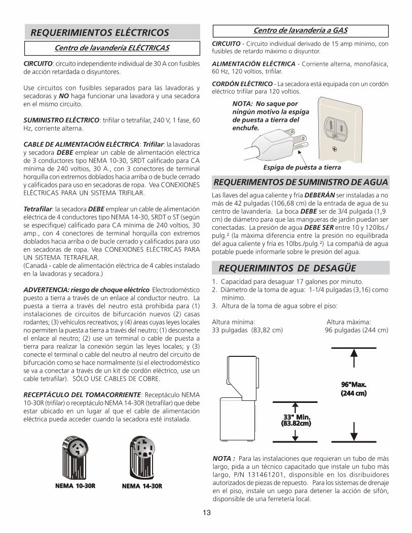
RECEPTÁCULO DEL TOMACORRIENTE: Receptáculo NEMA10-30R (trifilar) o receptáculo NEMA 14-30R (tetrafilar) que debeestar ubicado en un lugar al que el cable de alimentacióneléctrica pueda acceder cuando la secadora esté instalada.
NOTE: Do not underany circumstancesremove groundingprong from plug.
Grounding Prong
NOTA: No saque porningún motivo la espigade puesta a tierra delenchufe.
Espiga de puesta a tierra
Centro de lavandería a GAS
CIRCUITO - Circuito individual derivado de 15 amp mínimo, confusibles de retardo máximo o disyuntor.
ALIMENTACIÓN ELÉCTRICA - Corriente alterna, monofásica,60 Hz, 120 voltios, trifilar.
CORDÓN ELÉCTRICO - La secadora está equipada con un cordóneléctrico trifilar para 120 voltios.
REQUERIMENTOS DE SUMINISTRO DE AGUALas llaves del agua caliente y fría DEBERÁN ser instaladas a nomás de 42 pulgadas (106,68 cm) de la entrada de agua de sucentro de lavandería. La boca DEBE ser de 3/4 pulgada (1,9cm) de diámetro para que las mangueras de jardin puedan serconectadas. La presión de agua DEBE SER entre 10 y 120lbs./pulg.² (la màxima diferencia entre la presión no equilibradadel agua caliente y fría es 10lbs./pulg.²) La compañià de aguapotable puede informarle sobre le presión del agua.
REQUERIMINTOS DE DESAGÜE1. Capacidad para desaguar 17 galones por minuto.2. Diàmetro de la toma de agua: 1-1/4 pulgadas (3,16) como mínimo.3. Altura de la toma de agua sobre el piso:
Altura mínima: Altura màxima:33 pulgadas (83,82 cm) 96 pulgadas (244 cm)
33" Min. 33" Min. 33" Min. 33" Min. 33" Min.(83.82cm)(83.82cm)(83.82cm)(83.82cm)(83.82cm)
96"Max.96"Max.96"Max.96"Max.96"Max.(244 cm)(244 cm)(244 cm)(244 cm)(244 cm)
14
CORRECT CORRECT
No permita que los materiales combustibles (por ejemplo: laropa, cortinas/cortinajes, papel) tengan contacto con los ductos.El escape de la secadora NO DEBE dirigirse hacia el interior deuna chimenea, hacia una pared, hacia el cielo raso o hacia cualquierotro espacio reducido del edificio, donde puede ocurriracumulación de pelusas y constituir un peligro de incendio.
Exceder la longitud del conducto rigido o los números de codospermitidos en los diagramas "LARGO MÁXIMO" puede disminuirla capacidad de exhaustación del sistema. Obstruir el conductopuede provocar peligro de incendio, así como aumentar el tiempode secado.
No obstruya los extremos del tubo de ventilacion, ni utilicetornillos, remaches u otros medios de fijación que puedan obstruirel conducto y atrapar pelusa. Las pelusas podrían quedar atrapadasen los filtros, en los tornillos o en los remaches, lo cual obstruiría elsistema de escape y crearía un riesgo de incendio, así comotambién prolongaría el tiempo de secado. Use una caperuza desalida adecuada para el extremo del ducto que salga al exteriorde la vivienda y selle todas las juntas con cinta adhesiva para ductos.Todos los accesorios de tubería machos, DEBEN ser instalados aguasabajo del flujo de aire.
Riesgo de explosión. No instale la centrode lavadaría donde se guarda gasolina u otros materialesinflamables. Si la centro de lavadaríase instala en un garage, elladebe estar por lo menos 18 pulgadas (45,7 cm) por encima delsuelo. El incumplimiento puede resultar en la muerte, explosión,incendio, o quemaduras.1. La constrapresión del sistema de escape NO DEBE exceder 0,6 pulgadas (1,52 cm) de columna de agua, medida con un manómetro inclinado en la conexión del ducto de escape a la secadora.2. El sistema de escape debe ser inspeccionado y limpiado cada 2 años como mínimo, bajo condiciones de uso normal. Mientras màs se use la secadora, con mayor frecuencia deben inspeccionarse el sistema de escape y la caperuza de salida para verificar su buen funcionamiento.
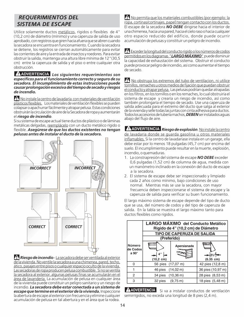
El largo màximo sistema de escape depende del tipo de ductoque se usa, del número de codos y del tipo de caperuza desalida. En la tabla se muestra el largo màximo tanto paraductos flexibles como rigidos.
Si va a instalar conductos de ventilaciónsemirrígidos, no exceda una longitud de 8 pies (2,4 m).
INCORRECT INCORRECT
0 56 pies (17,07 m) 42 pies (12,8 m)
1 46 pies (14,02 m) 36 pies (10,97 m)
2 34 pies (10,36 m) 28 pies (8,53 m)
3 32 pies (9,75 m) 18 pies (5,48 m)
TIPO DE CAPERUZA DE SALIDA(Preferido)
Número de Codos
a 90°
LARGO MÁXIMO del Conducto MetálicoRigido de 4” (10,2 cm) de Diámetro
4”
(10,2 cm)
Apersianada
(6.35 cm)2½"
REQUERIMIENTOS DEL SISTEMA DE ESCAPEUtilice solamente ductos metálicos, rígidos o flexibles de 4"(10,2 cm) de diámetro (mínimo) y una caperuza de salida de usoaprobado, con registros que giren hacia afuera que se abren cuandola secadora se encuentra en funcionamiento. Cuando la secadorase detiene, los registros se cierran automáticamente para evitarlas corrientes de aire y la entrada de insectos y roedores. Para evitarobstruir la salida, mantenga una altura libre mínima de 12"(30,5cm) entre la caperuza de salida y el piso o entre cualquier otraobstrucción.
Los siguientes requerimientos sonespecíficos para el funcionamiento correcto y seguro de susecadora. El incumplimiento de estas instrucciones puedecausar prolongación excesiva del tiempo de secado y riesgosde incendio.
No instale la centro de lavadaría con materiales de ventilaciónplásticos flexibles. Los materiales de ventilación flexibles se puedencolapsar o apachurrar fácilmente y atrapar pelusa. Estas condicionesobstruirán la circulación de aire de la Secadora de ropa y aumentaránel riesgo de incendio.Si su sistema de escape actual tiene ductos de plástico o de láminasmetálicas delgadas, reemplácelo con un ducto metálico rígido oflexible. Asegúrese de que los ductos existentes no tenganpelusas antes de instalar el ducto de la secadora.
Riesgo de incendio - La secadora debe ser ventilada al exteriorde la vivienda. No ventile la secadora a una chimenea, pared, techo,ático, pasajes entre pisos o cualquier espacio oculto de la vivienda.Las secadoras de ropa producen pelusa combustible. Si no se ventilala secadora al exterior, algunas pelusas finas se acumularán en elárea de lavandería. La acumulación de pelusa en cualquier áreade la vivienda puede constituir un peligro sanitario y un riesgo deincendio. La secadora debe estar conectada a un sistema deescape que termine en el exterior de la vivienda. Inspeccionela abertura de escape al exterior con frecuencia y elimine cualquieracumulación de pelusa en tal abertura y en el área que la rodea.
15
puede ser instalada directamente a través de la pared exterior.Para colocar el ducto de escape hacia arriba, añada un ducto 11pulgadas (27,94 cm) de longitud y 4 pulgadas (10,16 cm) dediàmetro y un ducto acodado de 90°. El artefacto debe estar aaproximadamente 4 1/2 pulgadas (11,43 cm) de la pared (se puedecolocar el ducto de escape paralelo con la pared colocàndolo debajode la secadora y dirigido hacia un lado). Para permitir el escapelateral o inferior, agregue un ducto de 8 pulgadas (20,32 cm) delargo y 4 pulgadas (10,16 cm) de diàmetro estàndar y un codo de90°.
REQUERIMIENTOS DEL SUMINISTRO DE GAS1. La instalación DEBE hacerse cumplir con los códigos locales o en
ausencia de los mismos, de acuerdo con los estandares del NationalFuel Gas Code (Código Nacional para Gases Combustibles), ANSIZ223.1 (la última editión). Para Canadá, el Estandar CAN/CGAB149 que esté en vigor.
2. La tubería de alimentación de gas debe ser de 1/2 pulgada(1,27 cm) de diámetro.
3. Si está permitido por los códigos locales, se puede usar tubería demetal para conectar su secadora a la línea de suministro de gas.La tubería DEBE ser fabricada de acero inoxidable o cobrerecubierto de plástico.
4. La tubería de alimentación de gas DEBE tener una llave de cierreindividual.
5. Una toma de 1/8 de pulgada (0,32 cm) N.P.T. accesible paraconexión del manómetro de prueba, DEBE ser instaladainmediatamente aguas arriba de la conexión de la tubería dealimentación de gas a la secadora.
6. La secadora DEBE ser desconectada del sistema de tuberías dealimentación de gas durante cualquier ensayo de presión delsistema de tuberías de alimentación de gas realizado a presionesde prueba de más de 1/2 lbs/pulg.2 (3,45 kPa).
7. La secadora DEBE aislarse del sistema de tuberías de alimentaciónde gas durante cualquier ensayo de presión del sistema de tuberíasde alimentación de gas realizado en ensayos de presión iguales oinferiores a 1/2 lbs/pulg.2 (3,45 kPa).
60 SQ. IN.(387.1 SQ. CM)
60 SQ. IN.(387.1 SQ. CM)
Closet Door
Pulg.²Pulg.²Pulg.²Pulg.²Pulg.²
Pulg.²Pulg.²Pulg.²Pulg.²Pulg.²
0 IN.(0 CM)
DRYER
WASHER
0 IN.(0 CM)
1 IN.(2.54 CM)
0 IN.(0 CM)
60 SQ. IN.(387.1 SQ. CM)
60 SQ. IN.(387.1 SQ. CM)
SECADORA
LAVADORA
Pulg.²
Pulg.²
Se puede colocar el ducto de escape de cuatro (4) manerasdistíntas cuando el artefacto està instalado con el fondo paralelocon la pared.1. Derecho hacia atràs.2. Hacia abajo - ducto rigido, 8 pulgadas (20.32 cm) de longitud y 4 pulgadas (10,16 cm) de diàmetro & 1 ducto acodado hacia abajo.3. Hacia la izquierda - ducto rigido, 8 pilgadas (20,32 cm) de longitud y 4 pulgadas (10,16 cm) de diàmetro, 1 ducto acodado hacia abajo y un ducto acodado hacia la derecha.4. Hacia la derecha - ducto rigido, 8 pulgadas (20,32 cm) de longitud y 4 pulgadas (10,16 cm) de diàmetro, 1 ducto acodado hacia abajo y un ducto acodado hacia la derecha.Aungue un sistema vertical sea aceptable, algunas circunstanciasatenuantes pueden afectar el funcionamiento de la secadora:• Se debe utilizar solamente conductos metalicos rigidos.• Una salida del sistema vertical en el
techo, puede exponerle a un corrientede aire descendente y disminuir así sucapacidad de exhaustación.
• El aislante que debe atravesar el sistemapuede causar condensación y disminuirasí la capacidad de exhaustación delsistema.
• La capacidad de exhaustación de un sistema de exhaustacióncomprimido o ondulado puede disminuirse.
Para colocar el ducto de escape hacia arriba, añada un ductode 11 pulgadas (27,94 cm) de longitud y de 4 pulgadas (10,16cm) de diàmetro y un ducto acodado de 90°. El artefactodebe estar a aproximadamente 4 1/2 pulgadas (11,43 cm) dela pared (Se puede colocar el ducto de escape paralelo con lapared por colocarlo debajo de la secadora y dirigirlo hacia unlado). Una caperuza de escape colocada en forma tal que sealinie con el escape de la secadora,
UBICACIÓN DE SU LAVANDERÍANO INSTALE SU LAVANDERÍ:1. En un lugar donde puede haber goteos de agua o quede expuesta a las inclemencias del tiempo.2. En un área donde pueda entrar en contacto con cortinas, cortinajes o cualquier otra cosa que obstruya el flujo de combustión y
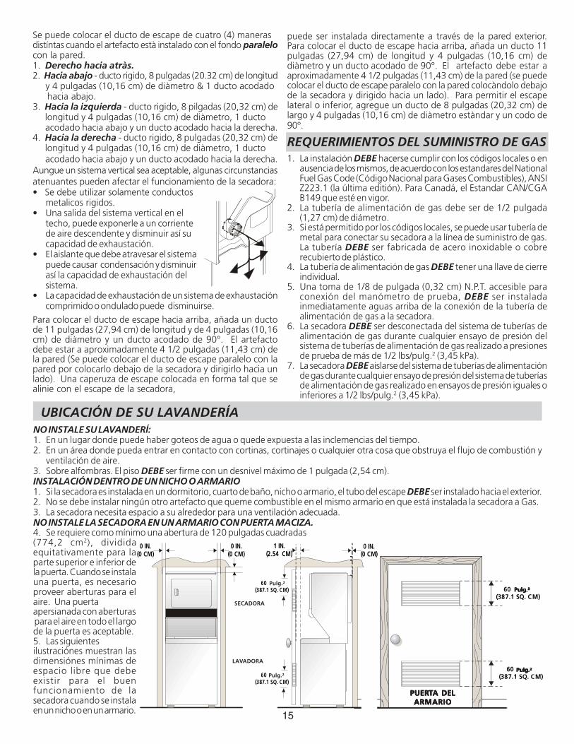
ventilación de aire.3. Sobre alfombras. El piso DEBE ser firme con un desnivel máximo de 1 pulgada (2,54 cm).INSTALACIÓN DENTRO DE UN NICHO O ARMARIO1. Si la secadora es instalada en un dormitorio, cuarto de baño, nicho o armario, el tubo del escape DEBE ser instalado hacia el exterior.2. No se debe instalar ningún otro artefacto que queme combustible en el mismo armario en que está instalada la secadora a Gas.3. La secadora necesita espacio a su alrededor para una ventilación adecuada.NO INSTALE LA SECADORA EN UN ARMARIO CON PUERTA MACIZA.4. Se requiere como mínimo una abertura de 120 pulgadas cuadradas(774,2 cm2), divididaequitativamente para laparte superior e inferior dela puerta. Cuando se instalauna puerta, es necesarioproveer aberturas para elaire. Una puertaapersianada con aberturas para el aire en todo el largode la puerta es aceptable.5. Las siguientesilustraciónes muestran lasdimensiónes mínimas deespacio libre que debeexistir para el buenfuncionamiento de lasecadora cuando se instalaen un nicho o en un armario.
PUERPUERPUERPUERPUERTTTTTA DELA DELA DELA DELA DELARMARIOARMARIOARMARIOARMARIOARMARIO
16
DIM
ENSI
ON
ES P
AR
A L
A IN
STA
LAC
ION
25 ¼
IN.
(64.
13 C
M)
3 ¾
IN.
(9.5
2 CM
)
4 13
/16
IN.
(12.
22 C
M)
9 3
/8 I
N.
(23.
81 C
M)
2 ½
IN.
(6.3
5 CM
)
47“
16 ¼
IN.
(41.
27 C
M)
36 1
/16I
N.
(91.
60 C
M)
30 1
3/16
IN.
(78.
26 C
M)
11 7
/16
IN.
(29.
5 CM
)
41 ¼
IN(1
04.7
7 C
M)
29 7
/16
IN(7
4.77
CM
)
27 IN
.(6
8.58
CM
)
DR
AIN
OU
TLET
(REA
R)
WA
TER
INLE
TS(R
EAR)
VEN
T1
7/8
IN.
(4.7
6 CM
)5
¼ IN
.(1
3.33
CM
)GA
S SU
PPLY
PIPE
(RE
AR
)
43 IN
.(1
09.2
2 C
M)
54 5
/16
IN.
(137
.95
CM
)
75 ½
IN.
(191
.77
CM
)
43 IN
.(1
09.2
2 C
M)
ELEC
TRIC
AL
CON
NEC
TIO
N
12 ½
IN.
(31.
75
CM
)
LIN
A D
E A
LIM
ENTA
TIO
ND
E G
AS
(ATR
AS)
CO
NEX
IÓN
ESEL
ÉCTR
ICA
S
ENTR
AD
AS
DE
AG
UA
(A
TRA
S)
SALI
DA
AL
DR
ENA
JE(A
TRA
S)
17
4. Saque: (a) la pieza de espuma que bloquea la cavidad; (b) la cinta de la puerta de la secadora; (c) las piezas de espuma para apoyar la seadora; (d) los tubos de entrada de agua; (e) el paquete.5. Saque las pinzas metàlicas del embalaje de la parte posterior de la lavadora, que sujetan el tubo de drenaje y el cable eléctrico. Hay abrazaderas de plàstico que sujetan el tubo de drenaje en labo derecho del resaldo de la lavadora. Estas abrazaderas forman una tuberîa vertical para prevenir el sifonaje de agua. NO SAQUE ESTAS ABRAZADERAS.6. Con cuidado, mueva el centro de lavanderia a cuatro pies (1,22 m) de su ubicación definitiva para la instalación final.
PLASTIC SPACERBLOCK
MECHANISMSHIPPINGBOLT
FOAMSHIPPINGPAD
DRAIN HOSE
POWER CORD(IF EQUIPPED)
SHIPPING CARTON CORNER POSTS
Bloqueespaciador deplàstico
Perno deembarque
Espumaprotectorade embareque Manguera de
desagüe
Cordon eléctrico (si viene el equipo)
INSTALACIÓN EN CASAS MÓVILES1. El tubo de escape de la secadora DEBE ser instalado hacia el
exterior (El escape debe colocarse en la parte exterior y nodebajo de la casa móvil.) Debe usarse ducto de metal que nosea combustible. El ducto de metal debe tener cuatro pulgadas(10,16 cm) de diámetro y no tener obstrucciones. Es preferibleusar ducto de metal que sea rígido.
2. Si el tubo de escape de la secadora corre a través del piso y elárea debajo de la casa móvil es cerrada, el ducto de escapeDEBE terminar fuera del recinto, con el extremo final aseguradoen contra de la estructura de la casa móvil.
3. Al instalar una secadora de gas en una casa móvil, hay queinstalar una provisión de aire fresco suplementario. La provisióntiene que ser más grande que dos veces el espacio del escapede la secadora.
4. Vea las páginas 2 y 3 para otros requísitos importantes deventilación.
5. La instalación DEBE cumplir con las estándares aplicables dela Manufactured Home Construction & Safety Standard -Estándares de Seguridad y Construcción de Casas Prefabricadas(Título 24 CFR - Parte 32-80 del Reglamento Federal) o cuandodichos estándares no sean aplicables, se deben complir conlos estándares de la American National Standard for MobileHomes (Estándares Nacionales Americanas para ViviendasMóviles). En Canadá se aplica el Estándar CSA Z240.
Esta secadora ha sido diseñada PARAUSO DOMESTICO solamente, de acuerdo con la norma ANSI Z21.5.1.
DESEMBALAJE1. Utilizando las cuatro esquineras de embarque de la caja de
cartón (dos a cada lado), coloque cuidadosamente la secadorasobre el costado izquierdo y saque la base de espuma deembarque.
Peso excesivo. Se necesitan dos o más personas para mover la Lavadora.
2. Utilizando la llave de tubo de 3/8 de pulgada (0,96 cm) saqueel perno de embarque y el bloque espaciador de plàtico delcentro de la base.
NOTA: Si el centro de lavandería via ser transportada a otrolugar a otra lugar posteriormente, conserve la espumade bloqueo de la tina, el perno de embarque y elespaciador de plàstico.
3. Vuelva a colocar el centro de lavanderia en la posición vertical
18
INSTALACIÓN ELÉCTRICA
TODAS los centro lavandoria ELÉCTRICAS
Los siguientes requerimientos sonespecíficos para el funcionamiento correcto y seguro de susecadora. El incumplimiento de estas instrucciones puedecausar prolongación excesiva del tiempo de secado y riesgosde incendio.
Este artefacto DEBE ser puesto a tierra demanera correcta. Si la lavanderia no está debidamente puesta atierra se puede producir un choque eléctrico. Siga las instruccionesindicadas en este manual para la puesta a tierra en forma correcta.
No use un cordón de extensión con estalavanderia. Algunos cordones de extensión no pueden soportar lacantidad de corriente eléctrica que utiliza esta secadora y puedenfundirse, creando un peligro de choque eléctrico y/o incendio.Ubique la lavanderia de manera que el cordón eléctrico lleguehasta el tomacorriente que se va a usar, dejando un poco de holgurapara el cordón. Consulte los requerimientos de instalaciónpreliminares indicados en este manual para el cordón eléctrico quedebe ser adquirido.
Se debe instalar un anclaje aprobado por elU.L. para el cordón eléctrico. Si no se utiliza un anclaje para sujetarel cordón eléctrico, éste puede salirse de la lavanderia y cortarsecon cualquier movimiento, resultando en un choque eléctrico.
No utilice un tomacorriente con cables dealuminio con un cordón y un enchufe de cobre (o viceversa). Seproduce una reacción química entre el cobre y el aluminio quepuede causar cortacircuitos. El cableado y tomacorrienteapropiado es un cordón eléctrico equipado con conductoresde cobre con un tomacorriente con conductores de cobre.
NOTA: Las lavanderia que operan con un suministro de energíade 208 voltios usarán más tiempo de secado que aquellas queoperan con un suministro de energía de 240 voltios.
REQUERIMIENTOS PARA LA PUESTA A TIERRA
Centro de lavanderia ELÉCTRICAS No canadienses
La conexión indebida del conductor de puestaa tierra del equipo puede ocasionar un riesgo de choque eléctrico.Consulte con un electricista profesional si tiene alguna duda respectoa la puesta a tierra correcta del artefacto.Para una secadora puesta a tierra, con cordón eléctrico:1. La lavanderia DEBE ser puesta a tierra. En caso de
malfuncionamiento o falla, la puesta a tierra reducirá el riesgode choque eléctrico proporcionando un trayecto de menorresistencia a la corriente eléctrica.
2. Si su lavanderia está equipada con un cordón eléctrico que poseeun conductor de puesta a tierra del equipo y un enchufe depuesta a tierra, dicho enchufe DEBE ser conectado a untomacorriente adecuado, debidamente instalado y puesto atierra de acuerdo con todos los códigos y reglamentos locales.Si tiene alguna duda consulte a un electricista profesional. Nomodifique el enchufe proporcionado la aplicación.
Para una lavanderia conectada permanentemente:1. La lavanderia DEBE ser conectada a un sistema de cableado
metálico permanente, puesto a tierra; o se debe instalar unconductor de puesta a tierra de equipo junto con losconductores del circuito y conectarse al borne de puesta a tierradel equipo o al cable del artefacto.
Centro de lavanderia ELÉCTRICAS canadienses
La conexión indebida del conductor de puestaa tierra del equipo puede ocasionar un riesgo de choque eléctrico.Consulte con un electricista profesional si tiene alguna dudarespecto a la puesta a tierra correcta del artefacto.
Para una lavanderia puesta a tierra, con cordón eléctrico:1. La lavanderia DEBE ser puesta a tierra.En caso de
malfuncionamiento o falla, la puesta a tierra reducirá el riesgode choque eléctrico proporcionando un trayecto de menorresistencia a la corriente eléctrica.
2. Si su lavanderia está equipada con un cordón eléctrico queposee un conductor de puesta a tierra del equipo y un enchufede puesta a tierra, dicho enchufe DEBE ser conectado a untomacorriente adecuado, debidamente instalado y puesto atierra de acuerdo con todos los códigos y reglamentos locales.Si tiene alguna duda consulte a un electricista profesional. Nomodifique el enchufe proporcionado la aplicación.
TODOS los centros lavanderia a GAS
Esta lavenderia está equipada con un enchufe de tres espigas (depuesta a tierra) para protección en contra de choques eléctricosy debe ser conectada directamenta en un receptáculo para tresespigas el cual debe estar puesto a tierra. No corte ni elimine laespiga de puesta a tierra de este enchufe.
CONEXIÓNES ELÉCTRICAS PARAUN SISTEMA TRIFILAR
Centro de lavanderia ELÉCTRICAS No canadienses
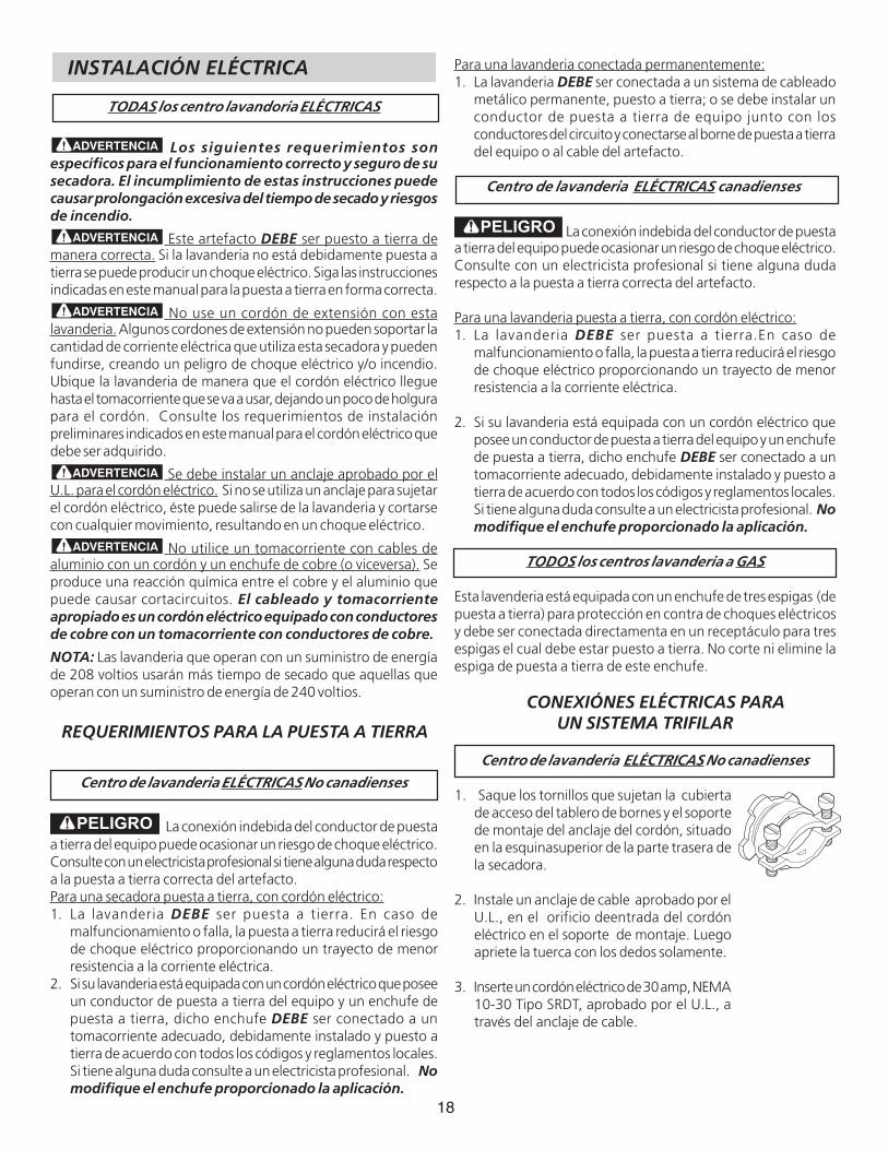
1. Saque los tornillos que sujetan la cubiertade acceso del tablero de bornes y el soportede montaje del anclaje del cordón, situadoen la esquinasuperior de la parte trasera dela secadora.
2. Instale un anclaje de cable aprobado por elU.L., en el orificio deentrada del cordóneléctrico en el soporte de montaje. Luegoapriete la tuerca con los dedos solamente.
3. Inserte un cordón eléctrico de 30 amp, NEMA10-30 Tipo SRDT, aprobado por el U.L., através del anclaje de cable.
19
CABLE DEPUESTA ATIERRANEUTR0
ROJO
NEGRO
BLANCO
CONDUCTOR VERDE DE CORDÓNELÉCTRICO
TORNILLO VERDEDE PUESTAA TIERRA
BORNE PLATEADO
CORDÓNELÉCTRICO
TABLERO DEBORNES
SOPORTEDE MONTAJE
DEL ANCLAJE DECABLE
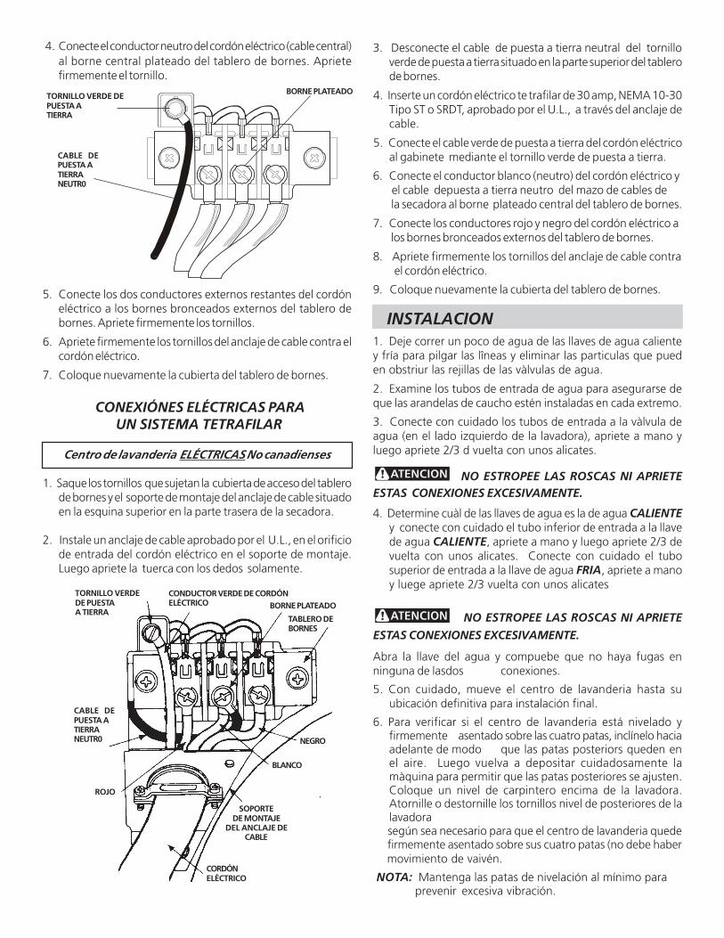
3. Desconecte el cable de puesta a tierra neutral del tornilloverde de puesta a tierra situado en la parte superior del tablerode bornes.
4. Inserte un cordón eléctrico te trafilar de 30 amp, NEMA 10-30Tipo ST o SRDT, aprobado por el U.L., a través del anclaje decable.
5. Conecte el cable verde de puesta a tierra del cordón eléctricoal gabinete mediante el tornillo verde de puesta a tierra.
6. Conecte el conductor blanco (neutro) del cordón eléctrico y el cable depuesta a tierra neutro del mazo de cables de la secadora al borne plateado central del tablero de bornes.
7. Conecte los conductores rojo y negro del cordón eléctrico a los bornes bronceados externos del tablero de bornes.
8. Apriete firmemente los tornillos del anclaje de cable contrael cordón eléctrico.
9. Coloque nuevamente la cubierta del tablero de bornes.
INSTALACION1. Deje correr un poco de agua de las llaves de agua calientey fría para pilgar las lîneas y eliminar las particulas que pueden obstriur las rejillas de las vàlvulas de agua.
2. Examine los tubos de entrada de agua para asegurarse deque las arandelas de caucho estén instaladas en cada extremo.
3. Conecte con cuidado los tubos de entrada a la vàlvula deagua (en el lado izquierdo de la lavadora), apriete a mano yluego apriete 2/3 d vuelta con unos alicates.
NO ESTROPEE LAS ROSCAS NI APRIETEESTAS CONEXIONES EXCESIVAMENTE.
4. Determine cuàl de las llaves de agua es la de agua CALIENTEy conecte con cuidado el tubo inferior de entrada a la llavede agua CALIENTE, apriete a mano y luego apriete 2/3 devuelta con unos alicates. Conecte con cuidado el tubosuperior de entrada a la llave de agua FRIA, apriete a manoy luege apriete 2/3 vuelta con unos alicates
NO ESTROPEE LAS ROSCAS NI APRIETE
ESTAS CONEXIONES EXCESIVAMENTE.
Abra la llave del agua y compuebe que no haya fugas enninguna de lasdos conexiones.
5. Con cuidado, mueve el centro de lavanderia hasta suubicación definitiva para instalación final.
6. Para verificar si el centro de lavanderia está nivelado yfirmemente asentado sobre las cuatro patas, inclínelo haciaadelante de modo que las patas posteriors queden enel aire. Luego vuelva a depositar cuidadosamente lamàquina para permitir que las patas posteriores se ajusten.Coloque un nivel de carpintero encima de la lavadora.Atornille o destornille los tornillos nivel de posteriores de lalavadora
según sea necesario para que el centro de lavanderia quede firmemente asentado sobre sus cuatro patas (no debe haber movimiento de vaivén.
NOTA: Mantenga las patas de nivelación al mínimo para prevenir excesiva vibración.
TORNILLO VERDE DEPUESTA ATIERRA
BORNE PLATEADO
CABLE DEPUESTA ATIERRANEUTR0
4. Conecte el conductor neutro del cordón eléctrico (cable central)al borne central plateado del tablero de bornes. Aprietefirmemente el tornillo.
5. Conecte los dos conductores externos restantes del cordóneléctrico a los bornes bronceados externos del tablero debornes. Apriete firmemente los tornillos.
6. Apriete firmemente los tornillos del anclaje de cable contra elcordón eléctrico.
7. Coloque nuevamente la cubierta del tablero de bornes.
CONEXIÓNES ELÉCTRICAS PARA UN SISTEMA TETRAFILAR
Centro de lavanderia ELÉCTRICAS No canadienses
1. Saque los tornillos que sujetan la cubierta de acceso del tablerode bornes y el soporte de montaje del anclaje de cable situadoen la esquina superior en la parte trasera de la secadora.
2. Instale un anclaje de cable aprobado por el U.L., en el orificiode entrada del cordón eléctrico en el soporte de montaje.Luego apriete la tuerca con los dedos solamente.
20
.
7 . CONEXIÓN DEL GAS (Secadoras a gas solamente) a. Saque la tapa de embarque de la tubería de gas de la
secadora situada en la parte trasera.
NOTA: NO conecte la lavandería al suministro de propano, sinprimero instalar el juego de conversión a propano. El juego deconversión a propano debe ser instalado por un técnico de gascalificado.
b.Conecte una tubería semirígida de 1/2" (1,27 cm) D.I. o una tubería aprobada, desde la línea de suministro de gas a la tubería de 3/8" (0,96 cm) ubicada en la parte trasera de la secadora. Utilice un reductor de 1/2" (1,27
cm) a 3/8" (0,96 cm) para la conexión. Aplique un sellador de roscas de uso aprobado, resistente a la corrosión de los gases licuados, en todas las uniones de la tubería.
c. Abra la válvula de cierre en la tubería de suministro degas.
d. Pruebe todas las conexiones aplicando con unaescobilla una solución jabonosa.
NUNCA UTILICE UNA LLAMA ABIERTA PARA DETECTARFUGAS DE GAS.
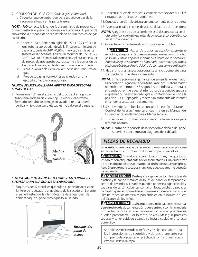
8. Forme una "U" en el extremo del tubo de drenage co el tubo señalando hacia el drenaje. Coloque el extremo formado del tubo de drenaje en lavadero or una tubería vertical y fíjelo con su sujetacables incluido en el paquete.
SI NO SE SIGUEN LAS INSTRUCCIONES ANTERIORE, ELSIFON SACARA EL AGUA DE LA LAVADORA.
9. Saque los dos (2) tornillos que sujen el panel de acceso de lantero de la secadora al gabinete de la secadora. Levante el panel hasta que las lengüetas se desenganchen del gabinet saque el panel y colóque lo a un lado.
Ataduradealambre
Tornillos delpanle deacceso
10. Conecte el ducto de escapeal sistema de escape exterior. Utilicecinta para obturar todas as uniones.
11.Conecte el cordón eléctrico a un tomacorriente puesto a tierra.
12. Vuelva a instalar el panel de acceso delantero de la seadora.
NOTA: Asegúrese de que la corriente esté desconectada en el disyuntor/caja de fusibles, antes de conectar el cordón eléctrico en el tomacorriente.
13.Conecte la corriente en el disyuntor/caja de fusibles.
Antes de poner en funcionamiento lasecadora, asegúrese de que no haya materiales combustibles,gasolina y otros vapores inflamables cerca de la secadora.Además asegúrese de que no haya nada (tal como cajas, ropas,etc.) que obstruya el flujo del aire de combustión y ventilación.
14. Haga funcionar la secadora durante un ciclo completo para comprobar su buen funcionamiento.
NOTA: En las secadoras a gas, antes de encender el quemadores necesario purgar el aire de la tubería del gas. Si el quemadorno enciende dentro de 45 segundos, cuando la secadora seenciende por primera vez, el interruptor de seguridad apagaráel quemador. Si ésto sucede, gire el contador de tiempo a laposición "OFF" (apagado) y espere 5 minutos antes de intentarencender la secadora nuevamente.
15.Si su lavandería no funciona, consulte la sección "Lista deControl de Averías" que se encuentra en su Manual delUsuario, antes de llamar para obtener servicio.
16.Conserve estas instrucciones cerca de la secadora parareferencia futura.
NOTA: Dentro de la consola de la secadora o debajo del panelsuperior se encuentra un diagrama del cableado.
PIEZAS DE RECAMBIOSi necesita obtener piezas de recambio para su secadora, póngaseen contacto con el distribuidor donde compró su secadora.
Cuando se reparan los controles, marque todoslos cables con etiquetas antes de desconectarlos. Cualquier errorde cableado puede causar una operación inadecuada y peligrosa.Asegúrese de que la secadora funcione adecuadamente despuésde repararla.
Destruya la caja de cartón, las bolsas deplástico y la banda metálica después de haber desempacado elcentro de lavandería. Los niños pueden ponerse a jugar con ellos.Las cajas de cartón cubiertas con alfombras, colchas o pedazosde plástico pueden convertirse en cámaras sin aire y causar asfixia.Elimine todos los materiales poniéndolos en la basura o fueradel alcance de los niños.
Las instrucciones incluidas en este manualy en el resto de la documentación que se entrega con la lavanderíano pueden cubrir todas las situaciones o condiciones posibles quepuedan presentarse. Por lo tanto, se DEBEN seguir prácticasseguras y tener cuidado cuando se instala cualquier artefactodoméstico.
Se obtiene el máximo de beneficios y resultadoscuando todaslas instrucciones de seguridad y defuncionamiento soncomprendidas y puestas en prácticade forma rutinaria cadavez que se lava la ropa
Top Related