UNIVERSIDAD TÉCNICA DEL NORTE - …repositorio.utn.edu.ec/bitstream/123456789/5674/2/INFORME...
18
UNIVERSIDAD TÉCNICA DEL NORTE FACULTAD DE INGENIERÍA EN CIENCIAS APLICADAS CARRERA DE INGENIERÍA EN ELECTRÓNICA Y REDES DE COMUNICACIÓN INFORME TÉCNICO TEMA: “ANÁLISIS DE RENDIMIENTO EN LOS ENLACES DE RADIO DE LA UNIVERSIDAD TÉCNICA DEL NORTE” AUTOR: CRISTIAN ANDRÉS RUALES HUACA DIRECTOR: ING. CARLOS ALBERTO VÁSQUEZ AYALA Msc. IBARRA-ECUADOR 2016
Transcript of UNIVERSIDAD TÉCNICA DEL NORTE - …repositorio.utn.edu.ec/bitstream/123456789/5674/2/INFORME...
UNIVERSIDAD TÉCNICA DEL NORTE
FACULTAD DE INGENIERÍA EN CIENCIAS APLICADAS
CARRERA DE INGENIERÍA EN ELECTRÓNICA Y REDES DE
COMUNICACIÓN
INFORME TÉCNICO
TEMA:
“ANÁLISIS DE RENDIMIENTO EN LOS ENLACES DE RADIO
DE LA UNIVERSIDAD TÉCNICA DEL NORTE”
AUTOR: CRISTIAN ANDRÉS RUALES HUACA
DIRECTOR: ING. CARLOS ALBERTO VÁSQUEZ AYALA Msc.
IBARRA-ECUADOR
2016

“ANÁLISIS DE RENDIMIENTO EN LOS
ENLACES DE RADIO DE LA
UNIVERSIDAD TÉCNICA DEL NORTE”
Cristian Andrés Ruales H.
Resumen - La Universidad Técnica del
Norte cuenta con seis extensiones
universitarias, al necesitar que cada una de
ellas tenga acceso a la red interna de la
misma se implementaron seis enlaces de
radio. Este proyecto tiene como objetivo
analizar y determinar el estado a nivel
físico y software de cada uno de los enlaces
de radio.
I. INTRODUCCIÓN
La Universidad Técnica del Norte está
creciendo tecnológicamente con el objetivo
de mejorar sus servicios, métodos
académicos y así cumplir con uno de los
requisitos básicos para la acreditación
académica. El área de Redes y
Comunicaciones del DDTI se encarga de la
administración de los 6 radioenlaces.
Los radio enlaces que se encuentran
activos no tuvieron una planificación ni
fueron dimensionados según las
necesidades por las cuales entraron en
funcionamiento. Al culminar este análisis
se podrá detectadas las necesidades y las
fallas de cada uno de los radio enlaces ya
mencionados, se sugerirá un modelo de
cambio y dimensionamiento según lo que
necesite cada uno de ellos, logrando
optimizar los recursos y capacidad de cada
equipo teniendo en cuenta las normas
establecidas para un radio enlace. Todo este
proceso será beneficiada la UTN ya que
necesita que sus radio enlaces estén
operando según las normas establecidas por
el ente regular que es la ARCOTEL.
II. MARCO TEÓRICO
2.1.- Enlace De Radio
Es una interconexión entre los
terminales de telecomunicaciones
efectuados por ondas electromagnéticas.
Los enlaces se hacen básicamente entre
puntos visibles. Una de sus mayores
características son la interoperabilidad y la
movilidad que pueden llegar a tener acceso
a lugares apartados sin necesidad de tener
una infraestructura física robusta.
2.2.- Enlace Punto A Punto
Este radio enlace permite interconectar
dos redes remotas como si fueran una sola
red. Dichos enlaces son viables desde 500
m. o menos hasta una distancia máxima
aproximada de 80 Km. La Figura 1 muestra
este tipo de conexión.
Figura 1. Enlace punto a punto
Fuente: Recuperado de
http://www.neoclan.net/pages/files/puntoapunto.jpg

Un radio enlace está conformado por los
siguientes componentes:
Antena
Power Over Ethernet (POE1)
Cable FTP2 (Foiled Twisted Pair)
Conector RJ-45 (Registered Jack)
Transmisor
Receptor
Línea de vista
2.3.- Plan Nacional de Frecuencias y Uso
del Espectro Radioeléctrico
Este plan establece la atribución de las
bandas de frecuencias a los diferentes
servicios de radiocomunicaciones. Para
este análisis se verificara que los enlaces de
radio estén usando las frecuencias en
función de los lineamientos EQA.50 y
EQA.90.
2.4.- UBIQUITI
Se dedica principalmente al diseño de
hardware de redes inalámbricas, tanto para
la comunicación a largas distancias, como
para el despliegue de pequeñas redes Wi-
Fi, priorizando la innovación y el alto
rendimiento a bajo coste.
2.5.- MIKROTIK
Es una compañía proveedora
de tecnología disruptiva de hardware y
software para la creación de redes, su
funcionalidad principal es convertir una
1 POE: Permite que la alimentación eléctrica se
suministre a un dispositivo de red, usando el
mismo cable que se utiliza para la conexión de
red 2 FTP: Par trenzado con blindaje global
PC o una placa Mikrotik RouterBOARD
en un router dedicado.
III. SITUACIÓN ACTUAL
Los enlaces de radio de la Universidad
Técnica del Norte están distribuidos como
se muestra en la Tabla 1.
Tabla 1. Distribución de enlaces de radio UTN
ENLACE ACCESS POINT ESTACIÓN
1
UTN Terraza
Edificio Central Lomas de Azaya
Lomas de Azaya Granja la Pradera
El enlace desde la Universidad Técnica del Norte hacia la
Granja La Pradera tiene un rebote ya que no existe línea de
vista directamente entre los dos puntos mencionados.
2 UTN Terraza CAI -
FICAYA Granja Yuyucocha
3 UTN Terraza
Edificio Central Colegio Universitario
4 UTN Terraza
Edificio Central Centro Infantil
5 UTN Terraza
Edificio Central
FCCSS(Antiguo
Hospital)
6 UTN Terraza
Edificio Central
Planta Textil (Estadio
Universitario)
Fuente: Universidad Técnica del Norte
El diagrama físico de los enlaces de
radio de la UTN se muestra en la Figura 2.
Figura 2. Diagrama Físico de los enlaces de radio de la UTN
Fuente: Universidad Técnica del Norte

3.1.- Análisis de Interferencias en el
Espectro Electromagnético
Para el análisis de frecuencias en cada
uno de los puntos de partida se utilizó las
siguientes herramientas:
AirView Spectrum Analyzer
Wireless Snooper
Cambium Spectrum Analyzer 2.5.1
En la Tabla 2 se detalla la frecuencia
con la cual están en funcionamiento y la
ubicación del equipo.
Tabla 2. Equipos ubicados en la terraza del Edificio
Central
ENLACE FRECUENCIA
UTN - AZAYA 5180 MHz
UTN – COLEGIO UNIVERSITARIO 5690 MHz
UTN – CENTRO INFANTIL 5230 MHz
UTN – FCCSS(ANTIGUO
HOSPITAL) 5200 MHz
UTN – PLANTA TEXTIL 5180 MHz
UTN CAI - YUYUCOCHA
5180 MHz
AZAYA – GRANJA PRADERA 5180 MHz
Fuente: Universidad Técnica del Norte
3.2.- Modelos de Equipos
En la Tabla 3 se especifica el modelo de
los equipos marca Ubiquiti que están
implementados.
Tabla 3. Equipos Ubiquiti Implementados
ENLACE DE
RADIO
MODELO DE ANTENA
Access Point Estación
Terraza Edificio
Central UTN –
Lomas de Azaya
NanoBridge
M5
NanoBridge
M5
Lomas de Azaya –
Granja La Pradera
NanoBridge
M5
NanoBridge
M5
Terraza Edificio
Central UTN –
Colegio
Universitario
NanoBridge
M5
NanoBridge
M5
Terraza Edificio
Central UTN -
Planta Textil
NanoStation 5
con pigtail y
grilla
--------------
Fuente: Universidad Técnica del Norte
En la Tabla 4 se especifica el modelo de
los equipos marca Mikrotik que están
implementados.
Tabla 4. Equipos Mikrotik Implementados
ENLACE DE
RADIO
MODELO DE ANTENA
Access Point Estación
Terraza
CAI/FICAYA –
Granja Yuyucocha
Tarjeta
RB411AH
con panel tipo
diamante
Tarjeta
RB411AH
con panel tipo
diamante
Terraza UTN -
Centro infantil
Tarjeta
RB411AH
con panel tipo
diamante
Tarjeta
RB411AH
con panel tipo
diamante
Terraza UTN -
FCCSS(Antiguo
Hospital)
Tarjeta
RB411AH
con panel tipo
diamante
Tarjeta
RB411AH
con panel tipo
diamante
Fuente: Universidad Técnica del Norte
3.3.- Análisis del Rendimiento y Consumo
de los Enlaces De Radio
A continuación se muestra un ejemplo
claro del desarrollo realizado para el
Enlace Terraza Edificio Central UTN –
COLEGIO UNIVERSITARIO
Los datos del enlace se muestran en
la Tabla 5.

Tabla 5. Datos del enlace Edificio Central UTN –
Colegio Universitario
PARÁMETROS VALOR
Tipo de Antena Parabólica
Potencia de Salida 23 dBm
Ganancia 22 dBi
Sensibilidad -96 dBm
Canal 48
Ancho de Canal 20 MHz
Frecuencia 5,8 GHz
Distancia 1 Km
Dirección IP Access Point 172.16.1.178/24
Dirección IP Estación 172.16.1.178/24
Fuente: Universidad Técnica del Norte
3.3.1.- Cálculos del Enlace
Los cálculos de los parámetros que no
existen en el datasheet son necesarios para
el trazado de los enlaces en el software y se
muestran en las ecuaciones 1, 2, 3 y 4.
Longitud de Onda: es la distancia real
que recorre una en un determinado
intervalo de tiempo.
[ ] [ ]
Ecuación 1. Fórmula de Longitud de Onda, Enlace Terraza
Edificio Central UTN – COLEGIO UNIVERSITARIO
FSL: es la cantidad de pérdida de
datos por le medio de transmisión al
realizar un enlace de radio.
( ) ( )
( ) ( )
[ ]
Ecuación 2. Fórmula de Pérdida en el espacio libre, Enlace
Terraza Edificio Central UTN – COLEGIO
UNIVERSITARIO
PIRE: es la cantidad de potencia que
distribuye a los dispositivos receptores
dentro de su alcance.
[ ]
Ecuación 3. Fórmula de Potencia Isotrópica Radiada
Equivalente, Enlace Terraza Edificio Central UTN – COLEGIO UNIVERSITARIO
Ecuación del Enlace: es el margen de
operatividad del sistema, es la señal
máxima que debe tener el enlace.
(
)
Cable UTP es 0
(
)
[ ]
Ecuación 4. Fórmula del margen de sensibilidad, Enlace
Terraza Edificio Central UTN – COLEGIO UNIVERSITARIO
3.3.2.- Estado del Enlace
En las Figuras 3 y 4 se puede apreciar el
rendimiento y la tasa de transmisión de las
tarjetas inalámbrica y LAN de los equipos
que realizan el Enlace de Radio, utilizando
las herramientas de Ubiquiti.
Realizando un análisis de la información
obtenida se puede llegar a concluir que el
nivel de rendimiento es totalmente eficaz y
la tasa de trasmisión que soporta el enlace
punto a punto es la cantidad necesaria para
brindar un servicio de calidad al Colegio

Universitario, vale recalcar que las
configuraciones de este enlace necesita
varios cambios que serán descritos
detalladamente en la última parte de este
proyecto.
Figura 3. Throughput Access Point, Enlace Edificio Central
UTN – COLEGIO UNIVERSITARIO
Fuente: Universidad Técnica del Norte
Figura 4. Throughput Estación, Enlace Edificio Central
UTN – COLEGIO UNIVERSITARIO
Fuente: Universidad Técnica del Norte
En las Figuras 5 y 6 presentadas se
realizó una medición de velocidad entre los
equipos de cada extremo, la información
que se obtuvo de este test es la cantidad de
información en Megabits por segundo que
recibe la estación.
Figura 5. Speed Test Access Point, Enlace Edificio Central
UTN – COLEGIO UNIVERSITARIO
Fuente: Universidad Técnica del Norte
Figura 6. Speed Test Estación, Enlace Edificio Central UTN
– COLEGIO UNIVERSITARIO
Fuente: Universidad Técnica del Norte
3.3.3.- Coordenadas Geográficas
Las coordenadas geográficas de las
ubicaciones de cada campus externo que
cuenta la UTN como se muestra en la Tabla
6.
Tabla 6. Coordenadas Geográficas
LUGAR LATITUD LONGUITUD
Universidad Técnica del
Norte 0°21'28.80"N 78° 6'39.10"O
Lomas de Azaya 0°22'40.10"N 78° 7'53.98"O
Granja La Pradera 0°21'22.14"N 78°12'24.96"O
Granja Yuyucocha 0°19'42.75"N 78° 7'52.10"O
Colegio Universitario 0°21'44.50"N 78° 7'6.19"O
Centro Infantil 0°20'48.10"N 78° 6'39.00"O
FCCSS (Antiguo
Hospital) 0°20'49.00"N 78° 6'51.10"O
Fuente: Universidad Técnica del Norte
IV. PLAN DE DIMENSIONAMIENTO
Después de haber realizado el análisis de
todas las partes que está conformado un
enlace de radio, existen equipos que
deberían ser sustituidos por las siguientes
razones.
Enlace UTN – AZAYA / AZAYA –
GRANJA PRADERA: Los
requerimientos que necesita la granja
la pradera esta sobre las capacidades
de los equipos.

Está totalmente saturado el
rendimiento del enlace antes analizado, en
esta extensión tuvo un aumento en gran
manera la cantidad de usuarios y de
dispositivos de red. Los dispositivos
actuales en funcionamiento no están
satisfaciendo las necesidades de este
campus.
Enlace UTN – FCCSS (Antiguo
Hospital SVP): Existe un error en la
tarjeta inalámbrica de la estación, se
desconecta cada cierto tiempo lo que
afecta en su totalidad la conectividad
hacia todos los servicios. Los pigtail
tienen una deterioración y están
aislados lo que hace que exista una
variación de potencia.
Enlace UTN – COLEGIO
UNIVERSITARIO: Este radio enlace
está cumpliendo con las necesidades
por no tener incremento de oficinas ni
laboratorios. Se realizaría un
mantenimiento a nivel de software y
físico para mejorar su funcionamiento
y optimizar sus capacidades.
Enlace UTN – GRANJA
YUYUCOCHA: Los equipos están en
total funcionamiento bridando total
conectividad a todos los servicios. La
corrección estaría enfocada más a la
parte del soporte en el cual está
ubicado el equipo estacionario ya que
no es el adecuado.
De la misma forma se realizaría un
mantenimiento a nivel de software y
físico para mejorar su funcionamiento
y optimizar sus capacidades.
Enlace UTN – CENTRO INFANTIL:
La tarjeta RB433AH de la estación se
reinicia intempestivamente y es
totalmente imposible tener acceso a la
red desde la guardería hacia los
servicios de la Universidad.
Enlace UTN – PLANTA TEXTIL:
Este es uno de los más preocupantes ya
que se están construyendo nuevas
instalaciones para esta facultad y los
equipos que están en funcionamiento
son demasiado antiguos lo cual da
muchos errores y un bajo rendimiento
del mismo teniendo varias
problemáticas y limitaciones de
conexión a la red interna.
V. PLAN DE MIGRACIÓN
Después haber desarrollado este
proyecto, están claras las problemáticas y
los diferentes errores a los que están
sometidos los seis enlaces de radio de la
Universidad Técnica del Norte. A
continuación sugeriré un modelo de equipo
que logre mejorar el rendimiento y la
capacidad, teniendo en cuenta las
características de cada enlace. Los dos
enlaces de radio que requieren más
capacidad por su planificación de
incremento en obra civil y por el aumento

de usuarios son los que se mencionan a
continuación:
Enlace UTN – AZAYA / AZAYA –
GRANJA PRADERA
Enlace UTN – PLANTA TEXTIL
Las opciones óptimas capaces de
satisfacer las necesidades de cada uno
teniendo en cuenta su funcionamiento a
largo plazo son los siguientes modelos:
Ubiquiti Rocket M5
Mikrotik BaseBox 5
Cualquiera de los dos equipos antes
detallados necesita de una antena Dish de
30 dBi, con estos equipos cumpliría con las
necesidades del enlace.
Al no tener un incremento o una
saturación en cada una de las extensiones
universitarias descritas a continuación:
Enlace UTN – FCCSS (Antiguo
Hospital SVP)
Enlace UTN – CENTRO INFANTIL
Los equipos de los Enlaces (UTN –
AZAYA / AZAYA – GRANJA PRADERA
y UTN – PLANTA TEXTIL) que serían
reemplazados por los modelos antes
sugeridos, pueden suplir las necesidades
que requiere cada extensión universitaria,
después de haberles realizado un
mantenimiento total como se ha
especificado anteriormente. En este caso
sería el cambio a equipos Ubiquiti
NanoBridge M5.
Mediante el análisis realizado
anteriormente se determinó que en los
siguientes dos enlaces descritos no se
encontraron problemáticas en los equipos,
por lo cual no existe fundamento real para
realizar un cambio de los mismos.
Enlace UTN – GRANJA
YUYUCOCHA
Enlace UTN – COLEGIO
UNIVERSITARIO
VI. BENEFICIOS DE LA
REALIZACIÓN DE LOS CAMBIOS
Al tomar en cuenta los cambios que se
recomiendan anteriormente, los enlaces de
radio adoptarían las siguientes
características:
Disponibilidad del servicio hacia
todos los servicios de la UTN.
Mejoraría el rendimiento de cada
equipo.
Cumplir con las necesidades y
requerimientos de las instalaciones.
El correcto funcionamiento y la
optimización de los equipos
beneficiara al desarrollo y avance
de la UTN, por ser un requisito de
acreditación el registro de los
enlaces de radio.

VI. CONCLUSIONES
Con la ayuda de libros, información y
varias herramientas inalámbricas se
consiguió analizar, identificar y detectar
cada uno de los parámetros con los que se
encuentran en funcionamiento los seis
enlaces de radio de la Universidad Técnica
del Norte, logrando determinar el nivel de
eficiencia con la que están brindando el
servicio a cada una de las extensiones de la
UTN, obteniendo determinar los errores y
proponiendo los correctivos necesarios.
Se verificó la frecuencia en cual está en
funcionamiento cada equipo Access Point,
basándose en las leyes que están
establecidas actualmente en el país por el
ente regulador, en cuanto a las
telecomunicaciones y uso del espectro
radioeléctrico que especifica claramente las
sanciones a cada una de las infracciones
cometidas,
Se logró tener en claro la situación
actual de configuraciones, estado y
funcionamiento de los equipos con la
realización del levantamiento de
información de los seis enlaces de radio.
Analizado el rendimiento y
funcionamiento se consiguió determinar los
cambios necesarios de equipos y la
corrección de errores en la parte de
configuraciones que se debe realizar para
tener un óptimo funcionamiento y un
rendimiento adecuado para cada uno de
ellos.
Al haber escogido un modelo
determinado el cual ayudó a corregir los
errores que se están suscitando en los seis
enlaces de radio ya implementados, se
obtuvo una guía aprobada sobre la
realización y planificación completa para el
desarrollo de los mismos logrando
dimensionar según las necesidades que se
requiera.
Con la ayuda de este análisis se puede
realizar varios cambios que ayudaran para
la regularización, ya que es parte de la
acreditación para la Universidad Técnica
del Norte tener registrado los enlaces de
radio ante el ente regulador.
VII. RECOMENDACIONES
Corregir todos los parámetros que se
encuentran con fallas a nivel físico y de
configuración en los equipos.
Realizar mantenimiento a todos los
dispositivos físicos activos y pasivos de
todos los radio enlaces.
Continuamente actualizar la versión de
firmware de cada dispositivo que brinda
cada fabricante.
Monitorear el rendimiento de cada uno
de los radio enlaces, logrando anticipar e
identificar algún tipo de error.
Realizar un barrido de todas las
frecuencias que se están usando en el medio
de transmisión para evitar interferencia y
pérdidas de la señal.
Utilizar la frecuencia permitida para una
identidad educativa pública según permita
el ente regulador. Se debe tener en cuenta la
definición de bandas libres dentro de los
marcos regulatorios, que dan la posibilidad
de utilizar esas porciones del espectro
electromagnético para la implementación
de redes a costos asequibles.
VIII. BIBLIOGRAFÍA
Agencia de Regulación y Control de
Telecomunicaciones. (11 de Julio
de 2011). Instructivo Formularios
Redes de Acceso Universal de
Internet. Obtenido de
www.arcotel.gob.ec/wp-
content/plugins/download-
monitor/download.php?id=579
Bateman, A. (2013). Comunicaciones
digitales: Diseño para el mundo
real. España: Marcombo.
Recuperado el 15 de 10 de 2015
París Diaz, M. (2008). Universidad Rey
Juan Carlos. Obtenido de
http://docencia.etsit.urjc.es/moodle/
mod/forum/discuss.php?d=11068&
parent=31700
Radiocomunicaciones.net. (2014).
Radioenlaces. Obtenido de
Radiocomunicaciones.net
Restrepo Angulo, J. (2010). Conceptos
Básicos de Ingeniería de
Radiopropagación. Compendio de
Telecomunicaciones #3. Medellín:
Universidad de Medellín.
Rodriguez, S. (2009). Modelo de Calidad
de Servicio para una Red de Datos
HSDPA. Santiago de Chile.
Salazar López, J. C., & Villegas Berny, P. I.
(22 de Octubre de 2012). Sistema
de un Enlace Punto a Punto /
Multipunto. Obtenido de
http://es.slideshare.net/PIVB/sistem
a-de-enlace-punto-a-multipunto
Universidad Técnica del Norte. (2016).
Universidad Técnica del Norte.
Obtenido de
http://www.utn.edu.ec/web/uniport
al/?page_id=2008
AUTOR
CRISTIAN ANDRÉS RUALES H.
Nacido en Ibarra,
Ecuador, el 02 de
Junio de 1989.
Realizó sus
estudios
secundarios en el
Colegio Fisco
misional “SAN
FRANCISCO” de
Ibarra. Estudiante
de la Universidad
Técnica del Norte en la Facultad de
Ingeniería en Ciencias Aplicadas, Carrera
de Electrónica y Redes de Comunicación
2016. Actualmente desempeña el puesto de
Técnico 2 en la empresa Soluciones
Avanzadas Informáticas Y
Telecomunicaciones SAITEL.

TECNICA DEL NORTE UNIVERSITY
FACULTY OF ENGINEERING IN APPLIED SCIENCES CAREER
IN ELECTRONIC AND COMMUNICATION’S NETWORKS
ENGINEERING
TECHNICAL REPORT
TOPIC:
"PERFORMANCE ANALYSIS OF RADIO LINKS THE TECNICA
DEL NORTE UNIVERSITY"
AUTHOR: CRISTIAN ANDRÉS RUALES HUACA
DIRECTOR: ENG. CARLOS ALBERTO VÁSQUEZ AYALA Msc.
IBARRA-ECUADOR
2016

"PERFORMANCE ANALYSIS OF RADIO
LINKS THE TECNICA DEL NORTE
UNIVERSITY"
Cristian Andrés Ruales H.
Summary.- The Tecnica del Norte
University has six university extensions, by
requiring that each has access to the
internal network of the same six radio links
were implemented. This project aims to
analyze and determine the status physically
and software of each of the radio links.
IX. INTRODUCTION
The Tecnica del Norte University is
growing technologically with the aim of
improving its services, academic methods
and thus fulfill one of the basic
requirements for academic accreditation.
The area DDTI Networks and
Communications is responsible for the
administration of the 6 radio links.
Radio links that are active or were not
planning were sized according to the needs
for which they became operational. Upon
completion of this analysis can be detected
needs and shortcomings of each radio links
already mentioned, a model of change and
sizing as you need each will be suggested,
thus optimizing resources and capacity of
each team taking account rules set for a
radio link. This whole process will benefit
the UTN because you need your radio links
are operating according to standards set by
the regulating body that is the ARCOTEL.
X. THEORETICAL FRAMEWORK
10.1.- Radio Link
It is an interconnection between
telecommunications terminals made by
electromagnetic waves. Links are basically
made between visible points.
One of its greatest features are
interoperability and mobility can have
access to remote locations without the need
for a robust physical infrastructure.
10.2.- Point to Point
This radio link allows interconnect two
remote networks as if they were a single
network. These links are viable from 500
m. or less up to a maximum distance of
approximately 80 km. Figure 6 shows this
type of connection.
Figura 6. Point to Point Source: Recovered From
http://www.neoclan.net/pages/files/puntoapunto.jpg
A radio relay network consists of the
following components:
Antenna
Power Over Ethernet (POE3)
Cable FTP4 (Foiled Twisted Pair)
RJ-45 (Registered Jack)
3 POE: Allows power to be supplied to a
network device using the same cable used for
network connection 4 FTP: Twisted pair with overall screen

Receiver Transmitter
Line of sight
10.3.- National Frequency Plan and Use of
Radio Spectrum
This plan provides for the allocation of
frequency bands to the various radio
services. This analysis verified that the
radio links using frequencies are based on
the guidelines EQA.50 and EQA.90.
10.4.- UBIQUITI
It is mainly engaged in the design of
wireless networking hardware for both
communication over long distances, as for
the deployment of small WiFi networks,
prioritizing innovation and high
performance at low cost.
10.5.- MIKROTIK
It is a disruptive technology provider
of hardware and software for networking
company, its main function is to converted
PC or MikroTik RouterBOARD plate on a
dedicated router.
XI. CURRENT SITUATION
Radio links Technical University
North are distributed as shown in Table 1.
Table 1. Distribution of radio links UTN
LINK ACCESS POINT STATION
1
UTN Terraza Edificio
Central Lomas de Azaya
Lomas de Azaya Granja la Pradera
The link from the Technical University Farm North towards
La Pradera has a rebound since there is no direct line of
sight between the two points mentioned.
2 UTN Terraza CAI -
FICAYA Granja Yuyucocha
3 UTN Terraza Edificio
Central Colegio Universitario
4 UTN Terraza Edificio
Central Centro Infantil
5 UTN Terraza Edificio
Central
FCCSS(Antiguo
Hospital)
6 UTN Terraza Edificio
Central
Planta Textil (Estadio
Universitario)
Source: Technica University North
Physical diagram of the radio links
UTN shown in Figure 7.
Figura 7. Physical diagram of the radio links UTN
Source: Technica University North
11.1 Analysis of interference in the
Electromagnetic Spectrum
Frequency analysis for each of the
starting points the following tools was used:
Spectrum Analyzer AirView
Wireless Snooper
Cambium Spectrum Analyzer 2.5.1
Table 2 shows the frequency with which
they are operating and vehicle location is
detailed.
Table 2. Equipment located on the terrace of the
Central Building
ENLACE FRECUENCIA
UTN - AZAYA 5180 MHz
UTN – COLEGIO UNIVERSITARIO 5690 MHz
UTN – CENTRO INFANTIL 5230 MHz
UTN – FCCSS(ANTIGUO HOSPITAL) 5200 MHz
UTN – PLANTA TEXTIL 5180 MHz
UTN CAI - YUYUCOCHA
5180 MHz
AZAYA – GRANJA PRADERA 5180 MHz
Source: Technica University North
11.2.- Equipment Models
Table 3 shows the model of brand
Ubiquiti equipment specified are
implemented.

Table 3. Equipment Ubiquiti Implemented
RADIO LINK ANTENNA MODEL
Access Point Station
Terraza Edificio
Central UTN –
Lomas de Azaya
NanoBridge
M5 NanoBridge M5
Lomas de Azaya
– Granja La
Pradera
NanoBridge
M5 NanoBridge M5
Terraza Edificio
Central UTN –
Colegio
Universitario
NanoBridge
M5 NanoBridge M5
Terraza Edificio
Central UTN -
Planta Textil
NanoStation 5
con pigtail y
grilla
--------------
Source: Technica University North
Table 4 shows the model Mikrotik brand
teams are implemented is specified. Table 4. Equipment Mkrotik Implemented
RADIO LINK ANTENNA MODEL
Access Point Station
Terraza
CAI/FICAYA –
Granja
Yuyucocha
Card
RB411AH with
diamond-panel
Card
RB411AH with
diamond-panel
Terraza UTN -
Centro infantil
Card
RB411AH with
diamond-panel
Card
RB411AH with
diamond-panel
Terraza UTN -
FCCSS(Antigu
o Hospital)
Card
RB411AH with
diamond-panel
Card
RB411AH with
diamond-panel
Source: Technica University North
11.3.- Performance Analysis and Consumer
radio links
Here is a clear example of the
development made for Central Terrace
Building Link UTN shown. The link data
shown in Table 5.
Table 5. Data link Central Building UTN -
College
PARÁMETER VALUE
Type of Antenna Parabólica
Output Power 23 dBm
Gain 22 dBi
Sensitivity -96 dBm
Channel 48
Channel width 20 MHz
Frequency 5,8 GHz
Distance 1 Km
Access Point IP Address 172.16.1.178/24
Access IP Address 172.16.1.178/24
Source: Technica University North
11.3.1 Calculations Link
The calculations of the parameters that
do not exist in the datasheet are necessary
for tracing the links in the software and are
shown in equations 1, 2, 3 and 4.
Wavelength: it is the actual distance
at a given time interval.
[ ] [ ]
Equation 1. Formula Wavelength, Terrace Central Link
Building UTN - COLLEGE
FSL: the amount of data loss by
transmission means him to make a
radio link.
( ) ( )
( ) ( )
[ ]
Equation 2. Loss Formula in free space, Terrace Central Link Building UTN – COLLEGE
PIRE is the amount of power
distributed to recipient devices
within range.
[ ]
Equation 3. Formula equivalent isotropically radiated
power, Terrace Central Link Building UTN - COLLEGE
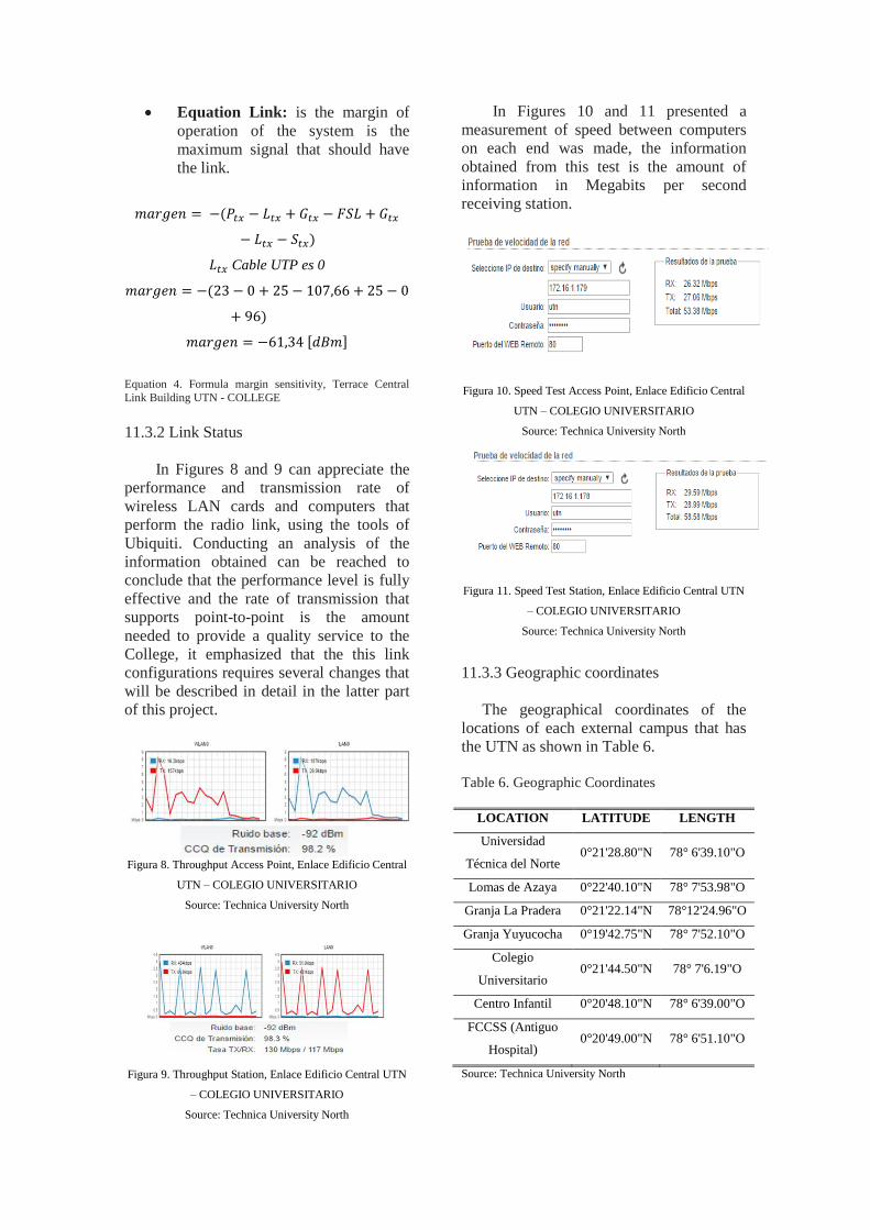
Equation Link: is the margin of
operation of the system is the
maximum signal that should have
the link.
(
)
Cable UTP es 0
(
)
[ ]
Equation 4. Formula margin sensitivity, Terrace Central
Link Building UTN - COLLEGE
11.3.2 Link Status
In Figures 8 and 9 can appreciate the
performance and transmission rate of
wireless LAN cards and computers that
perform the radio link, using the tools of
Ubiquiti. Conducting an analysis of the
information obtained can be reached to
conclude that the performance level is fully
effective and the rate of transmission that
supports point-to-point is the amount
needed to provide a quality service to the
College, it emphasized that the this link
configurations requires several changes that
will be described in detail in the latter part
of this project.
Figura 8. Throughput Access Point, Enlace Edificio Central
UTN – COLEGIO UNIVERSITARIO
Source: Technica University North
Figura 9. Throughput Station, Enlace Edificio Central UTN
– COLEGIO UNIVERSITARIO
Source: Technica University North
In Figures 10 and 11 presented a
measurement of speed between computers
on each end was made, the information
obtained from this test is the amount of
information in Megabits per second
receiving station.
Figura 10. Speed Test Access Point, Enlace Edificio Central
UTN – COLEGIO UNIVERSITARIO
Source: Technica University North
Figura 11. Speed Test Station, Enlace Edificio Central UTN
– COLEGIO UNIVERSITARIO
Source: Technica University North
11.3.3 Geographic coordinates
The geographical coordinates of the
locations of each external campus that has
the UTN as shown in Table 6.
Table 6. Geographic Coordinates
LOCATION LATITUDE LENGTH
Universidad
Técnica del Norte 0°21'28.80"N 78° 6'39.10"O
Lomas de Azaya 0°22'40.10"N 78° 7'53.98"O
Granja La Pradera 0°21'22.14"N 78°12'24.96"O
Granja Yuyucocha 0°19'42.75"N 78° 7'52.10"O
Colegio
Universitario 0°21'44.50"N 78° 7'6.19"O
Centro Infantil 0°20'48.10"N 78° 6'39.00"O
FCCSS (Antiguo
Hospital) 0°20'49.00"N 78° 6'51.10"O
Source: Technica University North

XII. SIZING PLAN
Having completed the analysis of all
parties is made a radio link, there are teams
that should be replaced by the following
reasons.
Link UTN - Azaya / azaya - PRAIRIE
FARM: The farm requirements needed
meadow is on the capabilities of the
equipment. Is fully saturated link
performance analyzed above, this
extension had greatly increased the
number of users and network devices.
Current devices running are not meeting
the needs of this campus.
Link UTN - FCCSS (Old Hospital
SVP): There is an error in the wireless
card from the station, it disconnects
every so often affecting entire
connectivity to all services. The pigtail
have a deterioration and isolated making
there is power variation.
Link UTN - COLLEGE: This radio
link is meeting the needs for not having
increasing offices or laboratories. level
maintenance software and hardware
would be made to improve its
performance and optimize its
capabilities.
Link UTN - FARM YUYUCOCHA:
The teams are fully operational and
bridling full connectivity to all services.
The correction would be focused more
on the part of the support on which is
located the stationary equipment
because it is not right.
Similarly maintenance would be done at
the level of software and hardware to
improve performance and optimize their
capabilities.
UTN Link - CHILD CENTER: The
card RB433AH station restarts
unexpectedly and it is totally impossible
to access the network from kindergarten
to University services.
UTN Link - TEXTILE PLANT: This
is one of the most worrying as they are
building new facilities for this faculty
and computers that are running are too
old which gives many errors and poor
performance of it having several
problems and limitations connection to
the internal network
XIII. IMMIGRATION PLAN
After having developed this project are
clear issues and the different errors that are
under six radio links Technical University
North. Then I will suggest a model of team
that achieves improved performance and
capacity, taking into account the
characteristics of each link. The two radio
links that require more capacity planning
increase in civil works and the increase
users are those listed below:
Link UTN - Azaya / Azaya - PRAIRIE
FARM
Link UTN - TEXTILE PLANT
The best options that meet the needs of
each given their long-term operation are the
following models:
Ubiquiti Rocket M5
Mikrotik base Box 5
Either before equipment needs a detailed
Dish antenna 30 dBi, fulfill these needs link
equipment.
Having no increase or saturation in each
of the university extensions described
below:
Link UTN - FCCSS (Old Hospital
SVP)
Link UTN - CHILD CENTER
The teams Links (UTN - Azaya / azaya
- FARM MEADOW and UTN - TEXTILE
PLANT) which would be replaced by the
previously suggested models, can meet the
needs required by each university
extension, after having made a total
maintenance as specified previously. In this
case it would change teams NanoBridge
Ubiquiti M5.

Through the above analysis it was
determined that in the following two links
described unproblematic in the teams met,
so there is no real basis for a change in
them.
Link UTN - FARM
YUYUCOCHA
Link UTN - COLLEGE
XIV. BENEFITS OF MAKING
CHANGES
By taking into account the changes
recommended above, the radio links take
the following characteristics:
Availability of service to all the
services of the UTN.
Would improve the performance of
each team.
Meeting the needs and requirements of
the facility.
The correct operation and optimization
of the equipment benefit the
development and advancement of the
UTN, as a requirement for accreditation
registration radio links.
XV. CONCLUSIONS
With the help of books, information
and various wireless tools it was achieved
analyze, identify and detect each of the
parameters that are in operation six radio
links Technical University Northern,
obtaining determine the level of efficiency
with they are providing service to each of
the extensions of the UTN, obtaining
determine errors and proposing the
necessary corrective measures.
The frequency which is operating each
team Access Point, based on the laws that
are currently established in the country by
the regulator, regarding
telecommunications and use of radio
spectrum which clearly specifies penalties
for each verified infringements.
It was possible to be clear about the
current situation of configurations, status
and operation of the equipment with the
completion of gathering information of the
six radio links.
Analyzed the performance and
operation was achieved determine the
necessary changes in equipment and error
correction on the part of configurations to
be performed for optimal performance and
adequate performance for each of them.
Having chosen a particular model
which helped correct the errors being raised
in the six radio links already implemented
an approved guidance on the
implementation and comprehensive
planning for their development was
obtained achieving dimensioned according
to the needs that required.
With the help of this analysis you can
make several changes to help for
regularization, since it is part of the
Technical University accreditation for
North have registered radio links to the
regulator.
XVI. RECOMMENDATIONS
Fix all parameters that are physically
flawed and equipment configuration.
Perform maintenance on all assets and
liabilities physical devices of all radio links.
Continuously update the firmware of
each device that provides each
manufacturer.
Monitor the performance of each radio
links, making anticipate and identify some
kind of error.
Perform a scan of all frequencies that
are being used in the transmission medium
to avoid interference and signal loss.
Use the frequency allowed for a public
educational identity as permitted by the
regulator.

XVII. BIBLIOGRAPHY
Agencia de Regulación y Control de
Telecomunicaciones. (11 de Julio
de 2011). Instructivo Formularios
Redes de Acceso Universal de
Internet. Obtenido de
www.arcotel.gob.ec/wp-
content/plugins/download-
monitor/download.php?id=579
Bateman, A. (2013). Comunicaciones
digitales: Diseño para el mundo
real. España: Marcombo.
Recuperado el 15 de 10 de 2015
París Diaz, M. (2008). Universidad Rey
Juan Carlos. Obtenido de
http://docencia.etsit.urjc.es/moodle/
mod/forum/discuss.php?d=11068&
parent=31700
Radiocomunicaciones.net. (2014).
Radioenlaces. Obtenido de
Radiocomunicaciones.net
Restrepo Angulo, J. (2010). Conceptos
Básicos de Ingeniería de
Radiopropagación. Compendio de
Telecomunicaciones #3. Medellín:
Universidad de Medellín.
Rodriguez, S. (2009). Modelo de Calidad
de Servicio para una Red de Datos
HSDPA. Santiago de Chile.
Salazar López, J. C., & Villegas Berny, P. I.
(22 de Octubre de 2012). Sistema
de un Enlace Punto a Punto /
Multipunto. Obtenido de
http://es.slideshare.net/PIVB/sistem
a-de-enlace-punto-a-multipunto
Universidad Técnica del Norte. (2016).
Universidad Técnica del Norte.
Obtenido de
http://www.utn.ed
u.ec/web/uniportal
/?page_id=2008
AUTHOR
CRISTIAN
ANDRÉS
RUALES H.
Born in Ibarra, Ecuador, June 02, 1989. He
completed his secondary education at the
College Treasury missionary "SAN
FRANCISCO" Ibarra. Student at the Technical
University of the North in the Faculty of
Engineering of Applied Science, Race
Electronics and Communication Networks 2016
currently holds the position of Technical 2 in
the company Advanced Computer Solutions and
Telecommunications SAITEL.