
Traducción del manual original - Avdel Global · Conjunto del émbolo 13 Conjunto del gatillo 14...
56
07287 07267 Máquina hidroneumática Manual de Instrucciones Traducción del manual original
Transcript of Traducción del manual original - Avdel Global · Conjunto del émbolo 13 Conjunto del gatillo 14...
07287
0726
7
Máqu ina h idroneumát ica
Manua l de I ns t rucc ionesTraducc ión de l manua l o r ig i na l

3
Normas de seguridad 4
EspecificacionesEspecificaciones de la máquina 5Dimensiones de la máquina 5
Uso previstoSelección de máquina 6
Puesta en servicioSuministro de aire 7Procedimiento de funcionamiento 7
BoquillasInstrucciones de montaje 8Componentes de la boquilla 07287 8Tablas de selección para Monobolt®, Avdelok®, Avtainer®, Maxlok® y Hemlok® 9Instrucciones de uso 9
AccesoriosKit de asa y soporte 10Adaptador de expulsión lateral 10Vaso recogeclavos 10Kit de conexión rápida y lista de piezas 11
Mantenimiento de la máquinaDiario/Semanal 12Datos de seguridad de la grasa de litio Moly EP 3753 12Kit de servicio 12Mantenimiento 13Vaso recogeclavos 13Conjunto del émbolo 13Conjunto del gatillo 14Unidad intensificadora 14Intensificadores de tracción y empuje 14Conjunto del regulador de presión y del filtro 15Conjunto del manómetro 15
Í nd ice
GARANTÍA LIMITADA
Avdel ofrece la garantía limitada de que sus productos estarán libres de defectos de fabricación y
materiales que se produzcan en condiciones de funcionamiento normales. Esta garantía limitada está
condicionada a: (1) que el producto sea instalado, mantenido y manejado de acuerdo con las instrucciones
y el folleto del producto y (2) a la confirmación por parte de Avdel de este defecto, tras una inspección y
prueba. Avdel ofrece la mencionada garantía limitada durante un periodo de doce (12) meses, a partir de
la entrega del producto de Avdel al comprador directo de Avdel. En caso de cualquier incumplimiento de
la mencionada garantía, el único remedio será la devolución de las mercancías defectuosas para su
reparación o el reembolso del precio de compra a discreción de Avdel. LA GARANTÍA EXPRESA LIMITADA
Y EL REMEDIO MENCIONADOS ANTERIORMENTE SON EXCLUSIVOS Y SUSTITUYEN A TODAS LAS DEMÁS
GARANTÍAS Y REMEDIOS. CUALQUIER GARANTÍA IMPLÍCITA RELATIVA A LA CALIDAD, IDONEIDAD PARA UN
FIN O COMERCIABILIDAD QUEDA, EN VIRTUD DEL PRESENTE DOCUMENTO, ESPECÍFICAMENTE
RECHAZADA Y EXCLUIDA POR PARTE DE AVDEL.
La política de Avdel UK Limited se centra en el desarrollo y la mejora continua del producto y por ello se reserva el derecho a cambiar las especificaciones de cualquier producto sin previo aviso.
Montajes generalesMontaje general del pistolín y lista de piezas 16-17Montaje general del conjunto manguera y lista de piezas 16-17Montaje general de la unidad intensificadora y lista de piezas 18-19Montaje general del intensificador de empuje y lista de piezas 20Montaje general del intensificador de tracción y lista de piezas 21
CebadoDetalles del aceite 22Datos de seguridad del aceite Hyspin® VG32 22Procedimiento de cebado 23Procedimiento de cebado alternativo 24
Diagnósticos de fallosSíntoma, causa posible y remedio 25

4
Normas de segur idad
1 No utilizar la máquina para otro propósito que no sea aquel para el que está diseñada.
2 No utilizar con esta herramienta/máquina otro equipo que no sea el recomendado y suministrado por Avdel.
3 Cualquier modificación realizada por el cliente en la herramienta/máquina, boquillas, accesorios o cualquier equipo suministrado
por Avdel o los representantes de ésta son responsabilidad del cliente. Avdel aconsejará con gusto sobre cualquier modificación
propuesta.
4 La herramienta/máquina debe mantenerse en condiciones seguras de funcionamiento en todo momento. Personal competente
entrenado debe efectuar comprobaciones a intervalos regulares en cuanto a daños y mal funcionamiento. Cualquier proceso de
desmontaje debe ser realizado sólo por personal entrenado en los procedimientos de Avdel. No desmonte esta
herramienta/máquina sin consultar antes las instrucciones de mantenimiento. Debe ponerse en contacto con Avdel para
conocer los requisitos de formación.
5 La herramienta/máquina deberá hacerse funcionar en todo momento bajo las indicaciones de la legislación de seguridad e
higiene aplicable. En el Reino Unido se aplica el acta "Health and Safety at Work Act 1974". Cualquier pregunta sobre el
funcionamiento correcto de la herramienta/máquina y sobre la seguridad del operario debe dirigirse directamente a Avdel.
6 El cliente debe explicar a los operarios las precauciones que se deben tomar cuando se usa esta herramienta/máquina.
7 Desconecte siempre la conexión neumática de la entrada de la herramienta/máquina antes de intentar ajustar, montar o retirar
una boquilla.
8 No haga funcionar la herramienta/máquina si ésta está dirigida hacia una persona o el operario.
9 Antes de hacer funcionar la herramienta/máquina adopte una postura estable y firme.
10 Debe asegurarse de que los orificios de ventilación no estén bloqueados ni tapados y que las mangueras estén siempre en
buenas condiciones.
11 La presión de funcionamiento no debe superar los 7 bares.
12 No haga funcionar la máquina si no incorpora el equipo de colocación completo a menos que se especifique lo contrario.
13 Debe prestar especial atención a que los vástagos gastados no se conviertan en un peligro.
14 Antes de hacer funcionar la máquina, se debe montar con un deflector de vástagos en buen estado.
15 Cuando la máquina se monta con un deflector de vástagos, se debe girar de modo que la abertura no quede encarada frente al
operario o cualquier otra persona que esté trabajando cerca.
16 Cuando se utilice la máquina, se recomienda la utilización de gafas de seguridad, tanto por parte del operario como de
cualquier persona que se encuentre en las proximidades, a fin de protegerse de la proyección de cualquier remache, en el caso
de que éste saliera despedido al aire. Se recomienda la utilización de guantes en el caso de que la aplicación incluya bordes o
esquinas afilados.
17 Tener cuidado en evitar que se enreden ropas sueltas, corbatas, cabello largo, trapos de limpiar, etc. en las partes móviles de
la máquina, que deben mantenerse secas y limpias para el mejor agarre posible.
18 Cuando transporte la máquina de un lugar a otro, mantenga las manos alejadas del gatillo para evitar una puesta en marcha
involuntaria.
19 Deberá evitar un contacto innecesario con el aceite hidráulico. Para minimizar la posibilidad de erupciones cutáneas, debe
tenerse la precaución de realizar un lavado a fondo.
20 Los datos C.O.S.H.H. del aceite hidráulico y de los lubricantes están disponibles en el proveedor de la máquina.
Cualquier persona que deba instalar, poner en funcionamiento o realizar el servicio de esta máquinadebe leerse este manual de instrucciones con especial atención en relación a las siguientes normas de seguridad.

5
Las dimensiones que se muestran en negrilla están en milímetros.Otras dimensiones están en pulgadas.
3000118.11
0726
7
652.5
63 Ø2.5 Ø
40 Ø1.6 Ø
1626.4
652.5
1706.7
50019.68
2509.84
40015.74
Presión de aire Mínima - Máxima 5-7 bares (72,5 – 101,5 psi)
Volumen de aire libre necesario a 5,5 bares 3,5 litros
Carrera Descarga mínima 29 mm (1,14 pulgadas)
Ciclo libre 32 mm (1,26 pulgadas)
Fuerza de tracción a 5,5 bares 32,4 kN
Tiempo de ciclo Aproximadamente 1,7 segundos
Nivel de ruido 75 dB(A)
Peso del pistolín (sin boquilla) 1,47 kg (3,23 lb)
Peso total Pistolín e intensificador(sin boquilla) 40 kg (88 lb)
Vibración Menos de 2,5 m/s2 (8,2 pies/s2)
Espec i f i cac iones
Espec i f icac iones de la máquina
Dimens iones de la máquina

6
Uso previsto
La máquina hidroneumática 07287 está diseñada para colocar remaches tipo perno-collar y remaches de rotura de vástago Avdel
® a alta velocidad; es ideal para para el montaje de lotes o de líneas en serie en una amplia variedad de aplicaciones en
todo tipo de industrias. La 07287 sigue la idea de un intensificador remoto separado del pistolín formado por; pistolín de remachado, mangueras de conexión, intensificador aire-aceite y unidad intensificadora (ver las páginas 5, 16, 18, 20 y 21). El pistolín montado con un deflector de vástagos es la herramienta estándar; no obstante como opción hay disponible un vaso recogeclavos y un accesorio de expulsión lateral (ver detalles en la página 10). También es posible adquirir sólo la herramienta básica (referencia 07287-00200) que viene sin boquilla.
Selección de máquina

7
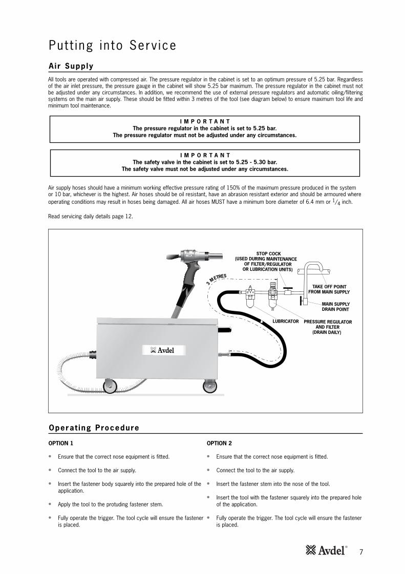
La máquina funciona con aire comprimido. El regulador de presión de la unidad intensificadora está ajustado para una presión óptimade 5,25 bares. Independientemente de la presión de aire de entrada, el medidor de presión de la unidad intensificadora mostrarácomo máximo 5,25 bares. El regulador de presión de la unidad intensificadora no se debe ajustar bajo ninguna circunstancia.Además, se recomienda utilizar reguladores de presión externos y sistemas automáticos de lubricación y filtrado en la alimentaciónde aire principal. Éstos se deben montar a una distancia máxima de 3 m de la máquina (véase el gráfico siguiente) para asegurar almáximo la vida útil de la máquina y reducir al mínimo el mantenimiento.
86
42
0
10121416
0726
7
Puesta en serv ic ioSumin is t ro de a i re
Proced imiento de func ionamiento
OPCIÓN 2
• Asegúrese de que ha montado el equipo de boquilla correcto.
• Conectar la máquina a la alimentación de aire.
• Insertar el vástago del remache en la boquilla de la máquina.
• Acercarse, con la pistola y el remache insertado en la boquilla,al taladro de la pieza e introducir completamente el cuerpo del remache.
• Accionar completamente el gatillo. El ciclo de la máquinaasegurará la correcta colocación del remache.
OPCIÓN 1
• Asegúrese de que ha montado el equipo de boquilla correcto.
• Conectar la máquina a la alimentación de aire.
• Insertar el cuerpo del remache completamente en el taladro de la pieza.
• Acercar la pistola a la pieza e introducir el vástago delremache en la boquilla.
• Accionar completamente el gatillo. El ciclo de la máquinaasegurará la correcta colocación del remache.
Las mangueras de suministro de aire tienen un presión de trabajo efectiva mínima del 150% respecto a la presión máximaproducida por el sistema o 10 bares, lo que sea más alto. Las mangueras de aire deben ser resistentes al aceite, tener una parteexterior resistente a la abrasión y se deben proteger cuando haya riesgo de que las condiciones de funcionamiento puedandañarlas. Todas las mangueras de aire DEBEN tener un diámetro mínimo de 6,4 mm o 1/4 pulgadas.
Consúltese la información del mantenimiento diario en la página 12.
I M P O R T A N T EEl regulador de presión de la unidad intensificadora está ajustado a 5,25 bares.
El regulador de presión no se debe ajustar bajo ninguna circunstancia.
I M P O R T A N T ELa válvula de seguridad de la unidad intensificadora está ajustada a 5,25 – 5,30 bares.
La válvula de seguridad no se debe ajustar bajo ninguna circunstancia.
PUNTO DE PARTIDA DE LA ALIMENTACIÓN
PRINCIPAL
PUNTO DE DRENAJEDE LA ALIMENTA-CIÓN PRINCIPAL
LUBRICADOR REGULADOR DE PRESIÓNY FILTRO
(DRENAJE DIARIO)
LLAVE DE CIERRE (SE USA DURANTE EL
MANTENIMIENTO DEL FILTRO/REGULADORES O EN LAS
UNIDADES DE LUBRICACIÓN)
3 METROS
8
Boqu i l l as
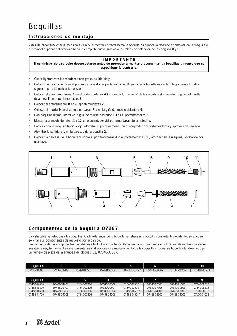
I M P O R T A N T EEl suministro de aire debe desconectarse antes de proceder a montar o desmontar las boquillas a menos que se
especifique lo contrario.
• Cubrir ligeramente las mordazas con grasa de litio Moly.
• Colocar las mordazas 5 en el portamordazas 4 o el portamordazas 3, según si la boquilla es corta o larga (véase la tablasiguiente para identificar las piezas).
• Colocar el aprietamordazas 7 en el portamordazas 4 (busque la forma en ‘V’ de las mordazas) o insertar la guía del muelledelantera 6 en el portamordazas 3.
• Colocar el amortiguador 8 en el aprietamordazas 7.
• Colocar el muelle 9 en el aprietamordazas 7 o en la guía del muelle delantera 6.
• Con boquillas largas, atornillar la guía de muelle posterior 10 en el portamordazas 3.
• Montar la arandela de retención 11 en el adaptador del portamordazas de la máquina.
• Sosteniendo la máquina hacia abajo, atornillar el portamordazas en el adaptador del portamordazas y apretar con una llave.
• Atornillar la sufridera 1 en la carcasa de la boquilla 2.
• Colocar la carcasa de la boquilla 2 sobre el portamordazas 4 o el portamordazas 3 y atornillar en la máquina, apretando conuna llave.
Ins t rucc iones de monta je
1 2 3 5 10 116 9
1 2 4 9 115 87
Componentes de la boqu i l la 07287
En esta tabla se relacionan las boquillas. Cada referencia de la boquilla se refiere a la boquilla completa. No obstante, se puedensolicitar sus componentes de repuesto por separado.Los números de los componentes se refieren a la ilustración anterior. Recomendamos que tenga en stock los elementos que debensustituirse regularmente. Lea atentamente las instrucciones de mantenimiento de las boquillas. Todas las boquillas también incluyenun número de pieza de la arandela de bloqueo 11, 07340-00327.
Antes de hacer funcionar la máquina es esencial montar correctamente la boquilla. Si conoce la referencia completa de la máquina odel remache, podrá solicitar una boquilla completa nueva gracias a las tablas de selección de las páginas 8 y 9.
BOQUILLA 1 2 4 5 7 8 9
BOQUILLA 1 2 3 5 6 9 1007498-00500 07497-03202 07498-00501 07498-00502 07497-03002* 07498-00507 07500-02005 07498-00503
07490-04900 07490-04400 07340-00306 07340-00304 07340-07502 07340-07503 07340-01503 07340-0150207498-01300 07498-01400 07340-00306 07340-00304 07340-07502 07340-07503 07340-01503 07340-0150207498-04600 07498-03202 07340-00306 07340-00304 07498-04501* 07498-04502 07498-03003 07100-0400307498-04700 07498-04701 07340-00306 07498-04503 07498-04501* 07498-04900 07498-03003 07100-04003
9
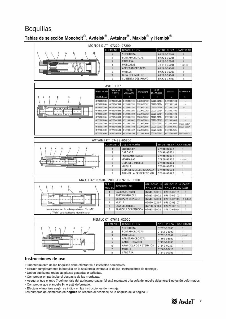
Boquillas
Tablas de selección Monobolt®
, Avdelok®
, Avtainer®
, Maxlok®
y Hemlok®
Instrucciones de uso
El mantenimiento de las boquillas debe efectuarse a intervalos semanales.
• Extraer completamente la boquilla en la secuencia inversa a la de las "Instrucciones de montaje".
• Deben sustituirse todas las piezas gastadas o dañadas.
• Comprobar en particular el desgaste de las mordazas.
• Asegurar que el tubo 7 del montaje del aprietamordazas (si está montado) o la guía del muelle delantera 6 no estén deformados.
• Comprobar que el muelle 9 no esté deformado.
• Efectuar el montaje según se indica en las instrucciones de montaje. Los números de elementos en negrilla se refieren al despiece de la boquilla de la página 8.
10
1 2
34
5
9
10
5
7
8
6
11
9
10
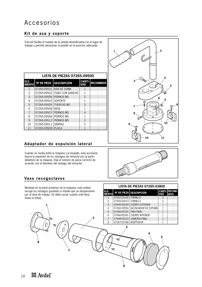
K i t de asa y sopor te
Accesor ios
LISTA DE PIEZAS 07265-09500
ELE-MENTO
123456789
1011
Nº DE PIEZA
07265-0950107265-0950207265-0950407265-0950307265-0950507265-0950807265-0950707265-0950607265-0951207265-0951107265-09509
DESCRIPCIÓN
ASA DE GOMATUBO CON GANCHOPERNOS M5SOPORTETUERCAS M5BASEPERNOS M5PERNOS M5PERNOS M5GRAPASPLACA
CANTI-DAD
11213141221
RECAMBIOS
-----------
Este kit facilita el manejo de la unidad intensificadora en el lugar detrabajo y permite almacenar el pistolín en la posición adecuada.
Adaptador de expu ls ión la tera l
Cuando se monta entre la máquina y la boquilla, este accesoriofuerza la expulsión de los vástagos de remache por la partedelantera de la máquina. Elija el número de pieza correcto deacuerdo con el diámetro del vástago del remache.
Vaso recogec lavos
Montada en la parte posterior de la máquina, esta unidadrecoge los vástagos gastados e impide que se desparramenpor el área de trabajo. Se debe vaciar cuando esté llenahasta la mitad.
LISTA DE PIEZAS 07265-03800
ELE-MENTO
12345678
Nº DE PIEZA
07267-0103907265-0201307640-0023907265-0205407340-0033507640-0024107498-0031007267-01038
DESCRIPCIÓN
TORNILLOTORNILLOCUERPO EXTERIORSILENCIADOR DE ESPUMATAPA FINALCUERPO INTERIORCUBIERTA FINALADAPTADOR
CANTI-DAD
32111111
RECAM-BIOS
--------
1
8
2
6
4
7
5
3

11
Ki t de conex ión ráp ida
1
2 3 9
4
1
5
6*14
*157 *16
8
9
10
11
9
1213
2
6
5
Accesor ios
LISTA DE PIEZAS 07267-01250ELEMENTO
123456789
10111213
* 14* 15* 16
Nº DE PIEZA
07265-0320607265-0326907265-0329507265-0929607265-0320407265-0320507265-0327507267-0102207265-0203107265-0327807267-0327707265-0327207265-0322107267-0325107267-0325207265-03292
DESCRIPCIÓN
TUERCACONEXIÓNEXTENSIÓN DEL TUBO NEUMÁTICOEXTENSIÓN DEL LATIGUILLO HIDRÁULICOARANDELATORNILLOCAJÓNCONECTORARANDELACONECTOR DE AJUSTE RÁPIDOACOPLADOR DE AJUSTE RÁPIDOARANDELACONECTORANILLO DE GOMAARANDELA ESPACIADORAABRAZADERA
CANTIDAD
4412441262212111
RECAMBIOS
----------------
* Estos elementos forman parte de la máquina básica, pero no del kit de conexión rápida.
Este kit permite una conexión rápida del pistolín y la manguera con la unidad intensificadora.

12
• Desmontar y limpiar la boquilla prestando especial atención a las mordazas. Lubricar con grasa de litio Moly EP 3753 antes devolverla a montar.
• Comprobar las fugas de aceite y las fugas de aire en la manguera de suministro de aire y en las conexiones.
La grasa se puede solicitar como un elemento único; el número de pieza se muestra en el siguiente kit de servicio.
Primeros auxilios
PIEL:Como la grasa es completamente resistente al agua, se elimina mejor con un limpiador cutáneo emulsificante aprobado.INGESTIÓN:Hacer que la persona beba 30 ml de leche de magnesia, preferiblemente en una taza. OJOS:Irritante pero no peligrosa. Irrigar con agua y buscar atención médica.Incendio
PUNTO DE INFLAMACIÓN: Por encima de 220 ºC.No está clasificada como inflamable.Medios extintores apropiados: CO2, Halón o rociado de agua si es aplicado por un operario experimentado.Medio ambiente
Recoger residuos para quemar o enviar al centro de residuos autorizado.Manejo
Usar crema de barrera o guantes resistentes al aceite.Almacenaje
Lejos del calor y de agentes oxidantes.
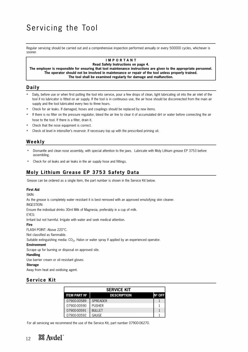
Para el mantenimiento completo aconsejamos utilizar el kit de servicio, número de pieza 07900-06270.
I M P O R T A N T ELea las instrucciones de seguridad de la página 4.
El cliente es el responsable de asegurar que se proporcionan al personal apropiado las instrucciones demantenimiento de la máquina. El operario no deberá verse implicado en el mantenimiento o reparación de lamáquina a menos que reciba la formación adecuada. La máquina deberá ser examinada de forma regular en
cuanto a daños y mal funcionamiento.
Manten imiento de la máqu ina
Diar io
Semanal
Datos de segur idad de la grasa de l i t io Moly EP 3753
• Cada día, antes de usar la máquina o cuando se ponga en servicio por primera vez, poner unas gotas de aceite lubricante ligeroen la entrada de aire de la máquina si no se ha montado un lubricador en el suministro de aire. Si la máquina se usa de formacontinua, la manguera de aire se debe desconectar de la alimentación principal y se debe lubricar la máquina cada dos o tres horas.
• Verificar la existencia de fugas de aire. Las mangueras y acoplamientos dañados se deben reemplazar por elementos nuevos.
• Si no hay un filtro en el regulador de presión, purgar la conexión neumática para limpiarla de la suciedad acumulada o del aguaantes de conectar la manguera de aire a la máquina. Si hay un filtro, vaciarlo.
• Comprobar que se ha montado el equipo de colocación correcto.
• Comprobar el nivel del aceite del depósito del intensificador. Si es necesario llenarlo con el aceite de cebado prescrito.
Se debe realizar un mantenimiento regular así como una inspección general anual o cada 500.000 ciclos, lo que se produzca antes.
Ki t de serv ic io
CANT.
111
ELEMENTO Nº DE PIEZA
07900-0058907900-0059007900-0059107900-00592
DESCRIPCIÓN
PORTAMORDAZASPROPULSORÉMBOLOMEDIDOR 1
KIT DE SERVICIO
13
Manten imiento de la máqu inaManten imiento
Vaso recogec lavos
Los números de elementos en negrilla se refieren al montaje general y a la lista de piezas de las páginas 16 y 17.
• La conexión neumática se debe desconectar para realizar el mantenimiento o antes de cualquier desmontaje a menos que seespecifique lo contrario.
• Se recomienda que cualquier trabajo de desmontaje se realice en un entorno limpio.
• Antes de desmontar la máquina se debe quitar la boquilla. Para las instrucciones de montaje véase la sección Boquillas en laspáginas 8 y 9.
• Extraer el tornillo de purga 18 y la arandela 19 del pistolín de la máquina y vaciar el aceite.
• Para un mantenimiento total de la máquina se recomienda continuar con el desmontaje de los submontajes en el orden que semuestra en el dorso de la página.
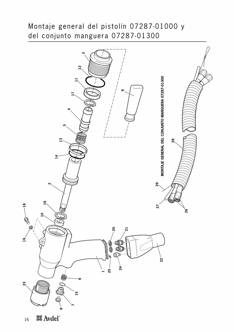
• Para desconectar los latiguillos de aceite 26 y el tubo neumático 27 del pistolín de la máquina, bajar el manguito protector 22para poder acceder a las conexiones.
• Desconectar el tubo neumático empujando y liberando el conector de conexión rápida. Mediante dos llaves fijas, aflojar loslatiguillos de aceite del conector 21, dejando el conector montado en el pistolín de la máquina. Retirar el pistolín de la máquina.
Los números de elementos en negrilla se refieren al despiece del vaso recogeclavos de la página 10.
• Para extraer el vaso recogeclavos de la máquina, aflojar los tres tornillos 1 y deslizar el adaptador del vaso recogeclavos 8conjuntamente con el vaso recogeclavos fuera de la tapa de cierre 3* (*en las páginas 16 y 17).
• Extraer dos tornillos 2 y separar el conjunto del receptor de vástagos del adaptador del receptor de vástagos.
• Montar en el orden contrario al del desmontaje.
Conjunto de l émbolo
Los números de elementos en negrilla se refieren al montaje general y a la lista de piezas de las páginas 16 y 17.
• Sujetar el pistolín de la máquina 1 en un tornillo de mordazas blandas y, sujetando con una llave fija las partes planas del resaltode la tapa de cierre 3, desatornillar ésta conjuntamente con el anillo tórico 12.
• Extraer el anillo tórico 12 de la ranura exterior de la tapa de cierre 3 y extraer la junta 11 del diámetro interior.
• Con los alicates extraer el anillo elástico 17 del émbolo 2 y retirar el soporte del deflector 4 y el muelle 5.
• Empujar el émbolo 2 fuera de la parte posterior de la máquina (durante esta operación se puede derramar aceite de la máquina).
• Con los alicates extraer el anillo elástico 16 del pistolín de la máquina y extraer el collarín estanco 10.
• Extraer el anillo tórico 14 y el anillo de grafito 13 del émbolo 2.
• Montar en orden inverso al del desmontaje, asegurándose de que las juntas 10, 11, 14 y el anillo de grafito 13 se montencorrectamente como se muestra en la página 16.
• Utilizar la herramienta de inserción del émbolo* para montar éste.
* Componente incluido en el kit de servicio.
I M P O R T A N T ELea las instrucciones de seguridad de la página 4.
El cliente es el responsable de asegurar que se proporcionan al personal apropiado las instrucciones demantenimiento de la máquina. El operario no deberá verse implicado en el mantenimiento o reparación de lamáquina a menos que reciba la formación adecuada. La máquina deberá ser examinada de forma regular en
cuanto a daños y mal funcionamiento.
Cada 500.000 ciclos la máquina se debe desmontar completamente y los componentes gastados, dañados o recomendados sedeben sustituir por otros nuevos. Se deben renovar todos los anillos tóricos y las juntas y se deben lubricar con grasa de litio Moly EP 3753 antes de volverlos a montar.
14
I M P O R T A N T E
Comprobar la máquina mediante el mantenimiento diario y semanalEl cebado es SIEMPRE necesario después de haber desmontado la máquina y antes de volver a ponerla
en marcha.
Manten imiento de la máqu ina
Conjunto de l gat i l lo
In tens i f icadores de t racc ión y empuje
Un idad in tens i f icadora
• Con una llave fija aflojar la contratuerca 7 y extraer el gatillo 6, el anillo tórico 15 y el muelle 8 del cuerpo de pistolín 1.
• Montar en el orden contrario al del desmontaje.
Los números de elementos en negrilla se refieren a los planos de montaje general y a la lista de piezas de las páginas 16-17.
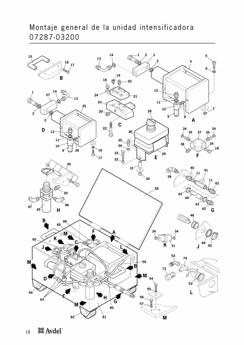
• La unidad intensificadora incluye dos intensificadores 4 y 25, una válvula de pilotaje 23, un conjunto de regulador de presión yfiltro 45 y un conjunto del manómetro 53 junto con los tubos neumáticos internos de la unidad intensificadora.
• El mantenimiento se limita a la extracción y sustitución de los conjuntos completos.
• Para desmontar la unidad intensificadora se debe extraer la placa base 61 y los componentes montados en ella. Esto es posibledespués de desmontar los tubos neumáticos y extraer los elementos que impiden la extracción de la placa base.
Los números de elementos en negrilla se refieren a los planos de montaje general y a la lista de piezas de las páginas 18-19.
• Para extraer los intensificadores 4, 25 y el depósito de aceite 36, desconectar los latiguillos de aceite con dos llaves fijas (tengaen cuenta que se puede derramar aceite de los latiguillos y del intensificador) y extraer los tubos neumáticos (conectores rápidos)que conectan el intensificador a la válvula de pilotaje.
• Con una llave fija extraer las dos tuercas y sus arandelas que aseguran el intensificador en la placa base.
• Levantar el intensificador de la unidad intensificadora.
• Montar en el orden contrario al del desmontaje.
Los números de elementos en negrilla se refieren a los planos de montaje general y a la lista de piezas de las páginas 18-19.
15
Los números de elementos en negrilla se refieren a los planos de montaje general y a la lista de piezas de las páginas 18-19.
Manten im iento de la máqu inaConjunto de l regu lador de pres ión y de l f i l t ro
Con junto de l manómetro
• Para extraer el conjunto del regulador de presión y del filtro 45 de la unidad intensificadora, desconectar los dos tubosneumáticos 59 y 63 del regulador.
• Extraer los dos tornillos, los espaciadores, las arandelas y las tuercas que aseguran el regulador en la unidad intensificadora.
• Extraer el conjunto de la unidad intensificadora.
• Montar en el orden contrario al del desmontaje.
• Para extraer el conjunto del manómetro 53, extraer el tubo neumático de la parte posterior del manómetro.
• Extraer la abrazadera de la parte posterior del manómetro y retirar el manómetro de la parte delantera de la unidadintensificadora.
• Montar en el orden contrario al del desmontaje.
• Después de cada desmontaje y montaje, el sistema SE DEBE cebar.
I M P O R T A N T EEl regulador de presión de la unidad intensificadora está ajustado a 5,25 bares.
El regulador de presión no se debe ajustar bajo ninguna circunstancia.
I M P O R T A N T ELa válvula de seguridad de la unidad intensificadora está ajustada a 5,25 – 5,30 bares.
La válvula de seguridad no se debe ajustar bajo ninguna circunstancia.
16
Monta je genera l de l p is to l í n 07287-01000 y de l con jun to manguera 07287-01300
6
7
19
23
18
14
10
16
13
2
54
11
31
2
17
15
8
1
20
25
21
22
9
27
29
28
26
24
MO
NTA
JE G
EN
ER
AL
DEL
CO
NJU
NTO
MA
NG
UER
A 0
7287-0
1300

17
Lista de piezas de 07287-01000 y 07287-01300
18
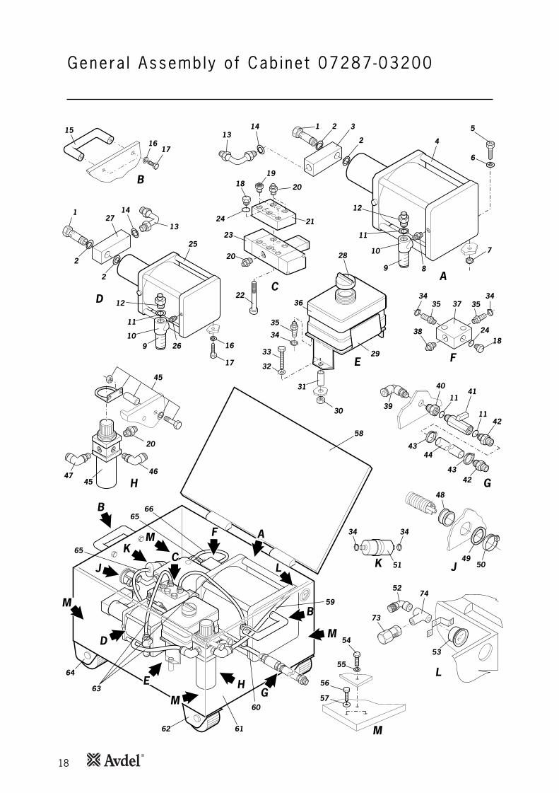
Monta je genera l de la un idad in tens i f i cadora 07287-03200
H
61
64
63
60
59
65
65
62
58
66
C
M
KM
J
G
B
M
B
A
M
E
D
F
L
14
A
4
5
6
7
1
9
10
2
2 313
8
11
12
B
15
1617
42
39
G
41
1142
11
40
4344
43
C22
1918
20
20
24 21
23
E29
30
31
28
32
33
36
35
34
H
20
46
45
4745
J
48
5049K
34 34
51
L
53
M
56
57
54
55
2714
D
25
16
1
910
2
2
13
26
11
12
17 F
3534
3534
1838 24
37
52
73
74
19
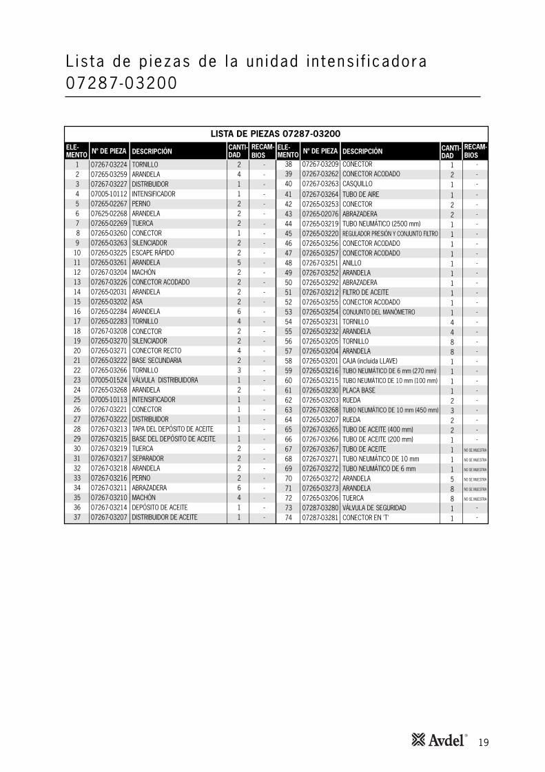
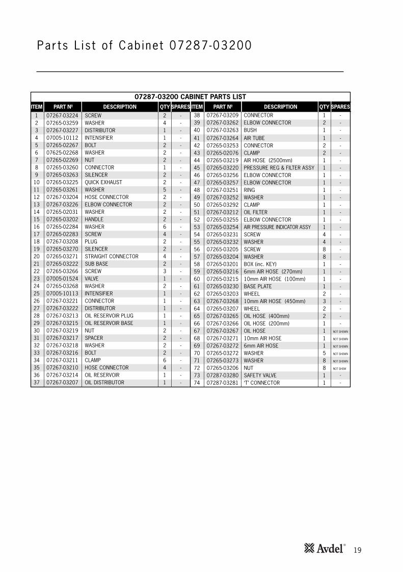
L is ta de p iezas de la un idad in tens i f i cadora 07287-03200
LISTA DE PIEZAS 07287-03200
ELE-MENTO
1234567 89
10111213141516171819202122232425262728293031323334353637
Nº DE PIEZA
07267-0322407265-0325907267-0322707005-1011207265-0226707625-0226807265-0226907265-0326007265-0326307265-0322507265-0326107267-0320407267-0322607265-0203107265-0320207265-0228407265-0228307267-0320807265-0327007265-0327107265-0322207265-0326607005-0152407265-0326807005-1011307267-0322107267-0322207267-0321307267-0321507267-0321907267-0321707267-0321807267-0321607267-0321107267-0321007267-0321407267-03207
TUERCA
VÁLVULA DISTRIBUIDORA
ABRAZADERA
DESCRIPCIÓN
TORNILLOARANDELA DISTRIBUIDORINTENSIFICADORPERNOARANDELA
CONECTORSILENCIADORESCAPE RÁPIDOARANDELAMACHÓNCONECTOR ACODADOARANDELAASAARANDELATORNILLO
SILENCIADORCONECTOR RECTO BASE SECUNDARIATORNILLO
ARANDELAINTENSIFICADORCONECTORDISTRIBUIDORTAPA DEL DEPÓSITO DE ACEITEBASE DEL DEPÓSITO DE ACEITETUERCASEPARADORARANDELAPERNO
MACHÓNDEPÓSITO DE ACEITEDISTRIBUIDOR DE ACEITE
CANTI-DAD
2411222122522226422423121111122226411
ELE-MENTO
38394041424344454647484950515253545556575859606162636465666768697071727374
Nº DE PIEZA
07267-0320907267-0326207267-0326307267-0326407265-0325307265-0207607265-0321907265-0322007265-0325607265-0325707267-0325107267-0325207265-0329207267-0321207265-0325507265-0325407265-0323107265-0323207265-0320507265-0320407265-0320107265-0321607265-0321507265-0323007265-0320307267-0326807265-0320707267-0326507267-0326607267-0326707267-0327107267-0327207265-0327207265-0327307265-0320607287-0328007287-03281
DESCRIPCIÓN
CONECTORCONECTOR ACODADOCASQUILLOTUBO DE AIRECONECTORABRAZADERATUBO NEUMÁTICO (2500 mm)REGULADOR PRESIÓN Y CONJUNTO FILTROCONECTOR ACODADOCONECTOR ACODADOANILLOARANDELAABRAZADERAFILTRO DE ACEITECONECTOR ACODADOCONJUNTO DEL MANÓMETROTORNILLOARANDELATORNILLOARANDELACAJA (incluida LLAVE)TUBO NEUMÁTICO DE 6 mm (270 mm)TUBO NEUMÁTICO DE 10 mm (100 mm)PLACA BASERUEDATUBO NEUMÁTICO DE 10 mm (450 mm)RUEDATUBO DE ACEITE (400 mm)TUBO DE ACEITE (200 mm)TUBO DE ACEITETUBO NEUMÁTICO DE 10 mmTUBO NEUMÁTICO DE 6 mmARANDELAARANDELATUERCAVÁLVULA DE SEGURIDADCONECTOR EN 'T'
CANTI-DAD
1211221111111111448811112322111158811
RECAM-BIOS
-----------------------------
--
NO SE MUESTRA
NO SE MUESTRA
NO SE MUESTRA
NO SE MUESTRA
NO SE MUESTRA
NO SE MUESTRA
RECAM-BIOS
------
------------------------------
-
CONECTOR

20
Monta je genera l de l i n tens i f i cador de empu je07005-10113
1
3
2
4 5 7 8 96 10 1211
14
13
15
16
17
19
20
24 25
21
22
23
18
L is ta de p iezas de l in tens i f icador de empuje 07005-10113
ELE-MENTO
123456789
10111213
Nº DE PIEZA
07267-0811907267-0810407267-0810707267-0812507267-0810607287-0810907267-0813407267-0813307287-0811707267-0811007267-0803107267-0811207267-08113
DESCRIPCIÓN
JUNTAJUNTABRIDA FRONTALARANDELATORNILLOVARILLAMUELLEGUÍA DEL MUELLECILINDRO NEUMÁTICOÉMBOLOARANDELAJUNTATUERCA
CANTI-DAD
4114411111118
RECAM-BIOS
-------------
LISTA DE PIEZAS DEL INTENSIFICADOR DE EMPUJE 07005-10113
ELE-MENTO
14151617181920212223242526
Nº DE PIEZA
07267-0801507267-0811607267-0813007287-0811407267-0812607267-0812207267-0810307287-0810207267-0812807267-0810107267-0812307267-0812107267-08135
DESCRIPCIÓN
CONTRATUERCABRIDA POSTERIOREXTENSIÓN DE VARILLAVARILLA DE TENSIÓNARANDELA DE MUELLEFILTROJUNTACABEZAL DE ACEROARANDELACONECTORARANDELATORNILLO DE PURGAFILTRO
CANTI-DAD
1114811111111
RECAM-BIOS
------------
NO SE MUESTRA
21
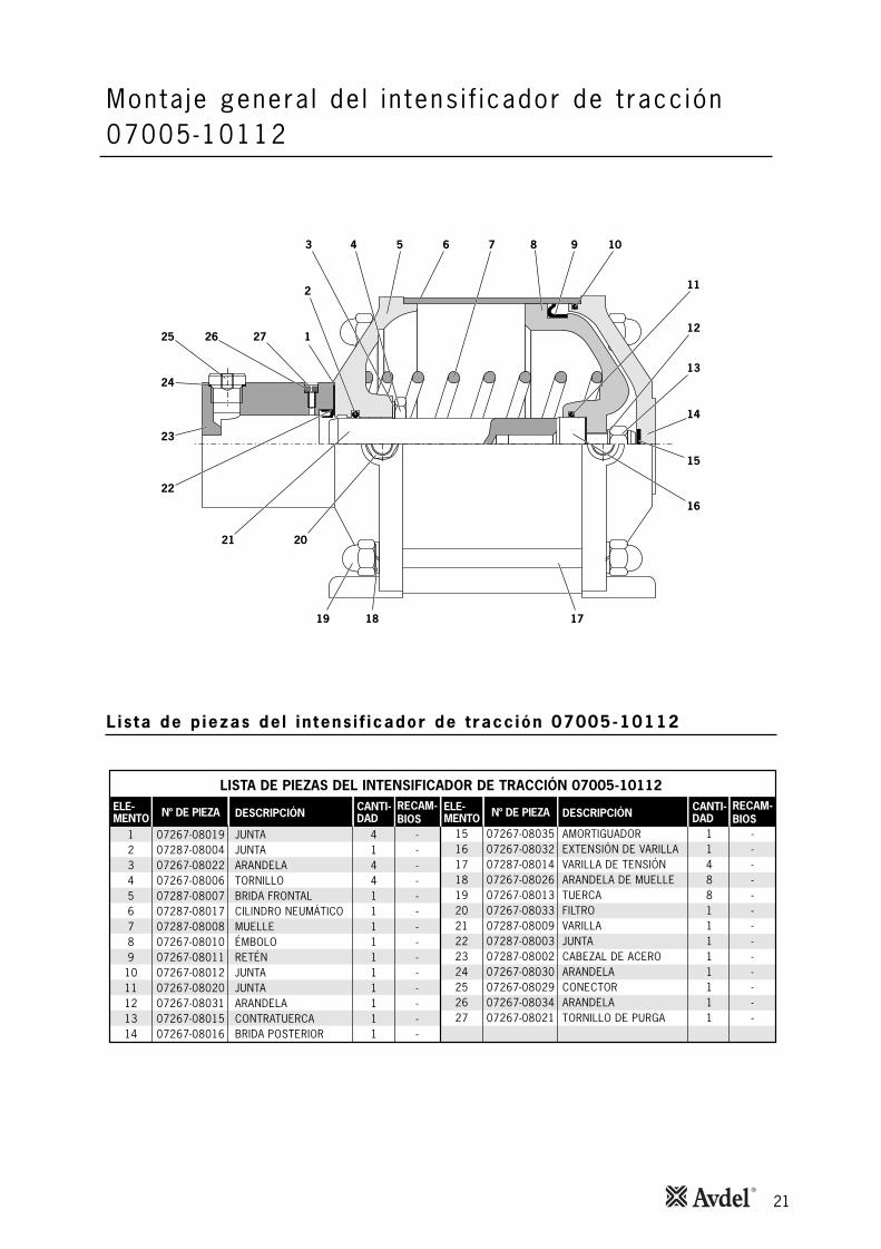
Monta je genera l de l i n tens i f i cador de t racc ión07005-10112
171819
16
15
14
12
13
11
1098743 65
2
1272625
24
23
22
21 20
L is ta de p iezas de l in tens i f icador de t racc ión 07005-10112
LISTA DE PIEZAS DEL INTENSIFICADOR DE TRACCIÓN 07005-10112
ELE-MENTO
123456789
1011121314
Nº DE PIEZA
07267-0801907287-0800407267-0802207267-0800607287-0800707287-0801707287-0800807267-0801007267-0801107267-0801207267-0802007267-0803107267-0801507267-08016
DESCRIPCIÓN
JUNTAJUNTAARANDELATORNILLOBRIDA FRONTALCILINDRO NEUMÁTICOMUELLEÉMBOLORETÉNJUNTAJUNTAARANDELACONTRATUERCABRIDA POSTERIOR
CANTI-DAD
41441111111111
RECAM-BIOS
--------------
ELE-MENTO
15161718192021222324252627
Nº DE PIEZA
07267-0803507267-0803207287-0801407267-0802607267-0801307267-0803307287-0800907287-0800307287-0800207267-0803007267-0802907267-0803407267-08021
VARILLA
DESCRIPCIÓN
AMORTIGUADOREXTENSIÓN DE VARILLAVARILLA DE TENSIÓNARANDELA DE MUELLETUERCAFILTRO
JUNTACABEZAL DE ACEROARANDELACONECTORARANDELATORNILLO DE PURGA
CANTI-DAD
1148811111111
RECAM-BIOS
-------------
22
Cebado
Deta l les de l ace i te
Datos de seguridad del aceite Hysp in® VG32
El cebado es SIEMPRE necesario después de haber desmontado la máquina y antes de volver a ponerla en marcha. También puedeser necesario restaurar la carrera completa después de un uso considerable, cuando se haya reducido la carrera de remachado ocuando para la colocación de un remache requiera más de una pulsación de gatillo.
El aceite recomendado para el cebado es el Hyspin® VG32, disponible en recipientes de 0,5 litros (nº de pieza 07992-00002) o de4,5 l (nº de pieza 07992-00006). Consulte los datos de seguridad a continuación.
Primeros auxiliosPIEL:Lavar a fondo con jabón y agua tan pronto como sea posible. El contacto casual no requiere ninguna atención inmediata. El contactoen un plazo corto no requiere una atención inmediata.INGESTIÓN:Pídase atención médica inmediatamente. NO se debe inducir al vómito.OJOS:Irrigar inmediatamente con agua durante varios minutos. Aunque NO es un irritante primario, puede producirse una irritación menortras el contacto.
Punto de inflamación232 °C. No está clasificado como inflamable.Medios extintores apropiados: CO2, polvo seco, espuma o niebla de agua. NO utilizar agua a presión.
Medio ambienteELIMINACIÓN DE RESIDUOS: A través de un contratista autorizado en un lugar permitido. Puede ser incinerado. El producto utilizado puede ser enviado para su recuperación.DERRAME:Impedir la entrada en desagües, cloacas y cursos de agua. Embeberlo con material absorbente.
ManejoUsar protección de ojos, guantes impermeables (por ejemplo de PVC) y un delantal de plástico. Usarlo en una zona bien ventilada.
AlmacenajeNo se requieren precauciones especiales.

23
I M P O R T A N T E
CONECTAR LA ALIMENTACIÓN DE AIRE (así se hace descender el émbolo, lo que permite que penetre másaceite de cebado en la máquina).
NO ACTIVAR EL GATILLO DURANTE LA EXTRACCIÓN DEL TORNILLO DE PURGA.Todas las operaciones deberán llevarse a cabo sobre un banco de trabajo limpio y con las manos limpias.DEBE prestarse atención en todo momento para asegurarse de que no se introduce en la máquina ninguna
materia extraña, ya que pueden producirse daños severos.
CebadoProced imiento de cebado
Los números de elementos en negrilla se refieren al montaje general y a la lista de piezas de las páginas 16 y 17.
• Antes de iniciar el procedimiento de cebado, se ha de tener a mano un contenedor capaz de recoger el exceso de aceite.
• Desconectar al alimentación de aire y aflojar la tapa del deposito de aceite del intensificador.
• Llenar el depósito del armario con aceite de cebado VG32 Hyspin® hasta el nivel de 20 mm (0,8") de la parte superior deldepósito.
• Extraer el tornillo de purga 18 y la arandela 19 de la parte delantera de la máquina.
• Conectar la máquina al suministro de aire.
• PRESTAR ESPECIAL ATENCIÓN A QUE LOS ORIFICIOS DE PURGA NO ESTÉN ENCARADOS DIRECTAMENTE HACIA ELOPERARIO U OTRAS PERSONAS.
• Colocar el asa de la máquina sobre el contenedor con el orificio de purga orientado hacia el contenedor y activar el gatillo.
• Una vez se haya expulsado el aceite por el orificio de purga, soltar el gatillo.
• Activar de nuevo el gatillo, volver a colocar el tornillo de purga 18 y la arandela 19 en la parte delantera de la máquina ANTESde soltar el gatillo.
• Desconectar la máquina de la manguera de aire.
• Extraer el tornillo de purga 18 y la arandela 19 de la parte posterior de la máquina.
• Conectar la máquina al suministro de aire.
• Activar el gatillo hasta que se haya expulsado el aceite por el orificio de purga. Soltar el gatillo y volver a colocar el tornillo depurga 18 y la arandela 19 en la parte posterior de la máquina.
• Repetir la secuencia de activar y desactivar el gatillo, con intervalos de algunos segundos, para permitir que circule el aceite decebado.
• Continuar hasta que el aceite fluya por ambos orificios de purga sin burbujas (hay que asegurarse de que el depósito de aceiteno esté vacío, ya que de lo contrario el aire se puede introducir en el sistema y formar burbujas en la corriente de aceite).
• Cuando por ambos orificios salga aceite sin aire, active el gatillo y apriete el tornillo de purga con una llave Allen. Suelte algatillo y apriete el tornillo de purga posterior con una llave Allen.
• Si es necesario llene el depósito de aceite.
24
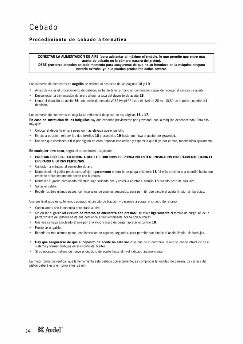
CebadoProcedimiento de cebado a l ternat ivo
CONECTAR LA ALIMENTACIÓN DE AIRE (para adelantar al máximo el émbolo, lo que permite que entre másaceite de cebado en la cámara trasera del pistón).
DEBE prestarse atención en todo momento para asegurarse de que no se introduce en la máquina ningunamateria extraña, ya que pueden producirse daños severos.
Los números de elementos en negrilla se refieren al despiece de las páginas 18 y 19.
• Antes de iniciar el procedimiento de cebado, se ha de tener a mano un contenedor capaz de recoger el exceso de aceite.
• Desconectar la alimentación de aire y aflojar la tapa del depósito de aceite 28.
• Llenar el depósito de aceite 36 con aceite de cebado VG32 Hyspin® hasta el nivel de 20 mm (0,8") de la parte superior deldepósito.
Los números de elementos en negrilla se refieren al despiece de las páginas 16 y 17.
En caso de sustitución de los latiguillos hay que cebarlos previamente por gravedad, con la máquina desconectada. Para ellohay que:
• Colocar el depósito en una posición más elevada que el pistolín.
• En dicha posición, extraer los dos tornillos 18 y arandelas 19 hasta que fluya el aceite por gravedad.
• Una vez que comience a fluir por alguno de ellos, taponar ese orificio y esperar a que fluya por el otro, taponándolo igualmente.
En cualquier otro caso, seguir el procedimiento siguiente:
• PRESTAR ESPECIAL ATENCIÓN A QUE LOS ORIFICIOS DE PURGA NO ESTÉN ENCARADOS DIRECTAMENTE HACIA ELOPERARIO U OTRAS PERSONAS.
• Conectar la máquina al suministro de aire.
• Manteniendo el gatillo presionado, aflojar ligeramente el tornillo de purga delantero 18 (el más próximo a la boquilla) hasta queempiece a fluir lentamente aceite con burbujas.
• Mantener el gatillo presionado mientras siga saliendo aire y volver a apretar el tornillo 18 cuando cese de salir aire.
• Soltar el gatillo.
• Repetir los tres últimos pasos, con intervalos de algunos segundos, para permitir que circule el aceite limpio, sin burbujas.
Una vez finalizado esto, tenemos purgado el circuito de tracción y pasamos a purgar el circuito de retorno.
• Continuamos con la máquina conectada al aire.
• Sin pulsar el gatillo (el circuito de retorno se encuentra con presión), se afloja ligeramente el tornillo de purga 18 de laparte trasera del pistolín hasta que comience a fluir lentamente aceite con burbujas.
• Una vez se haya expulsado el aire por el orificio trasero de purga, apretar el tornillo 18.
• Presionar el gatillo.
• Repetir los tres últimos pasos, con intervalos de algunos segundos, para permitir que circule el aceite limpio, sin burbujas.
• Hay que asegurarse de que el depósito de aceite no esté vacío ya que de lo contrario, el aire se puede introducir en elsistema y formar burbujas en el circuito de aceite).
• Si es necesario, rellene de nuevo el depósito de aceite hasta el nivel indicado anteriormente.
La mejor forma de verificar que la herramienta está cebada correctamente, es comprobar la longitud de carrera. La carrera delpistón deberá esta en torno a los 32 mm.

Síntoma Causa pos ib le Remedio Página de re ferenc ia
Otros síntomas o fallos deben notificarse a su distribuidor autorizado Avdel® o un centro de reparaciones.
25
D iagnóst icos de fa l los
Se necesitan
pulsaciones para
colocar el
remache
La máquina no
agarra el vástago
del remache
La máquina no
rompe el vástago
o perno
La máquina no
deforma el collar
Presión de aire baja
Falta de lubricación
Mordazas rotas o desgastadas
Nivel de aceite muy bajo o hay aire
en el aceite
Mordazas rotas o sucias
Portamordazas suelto
Muelle roto o debilitado en
el interior de la boquilla
Componente incorrecto en la boquilla
Presión de aire insuficiente
Longitud del perno incorrecta
Se ha de cebar la máquina
Silenciador de escape sucio
Válvula de pilotaje sucia
Presión de aire insuficiente
Carcasa de estampación gastadas
Se ha de cebar la máquina
Carcasa de estampación resquebrajada
Longitud del perno incorrecta
Aumentar la presión del aire
Lubricar el punto de entrada de aire de
la máquina
Colocar nuevas mordazas
Cebar la máquina
Limpiar las mordazas o montar nuevas
mordazas
Apretar contra arandela de retención de nylon
Colocar nuevo muelle
Identificar y sustituir
Ajustar presión/fugas de aire
Cambiar por un perno de la longitud correcta
Volver a cebar la máquina
Limpiar el silenciador
Extraer o limpiar la válvula
Ajustar presión/fugas de aire
Sustituir
Volver a cebar la máquina
Sustituir
Cambiar por un perno de la longitud correcta
7
12
8
22-24
8
8
8
8
7
22-24
7
22-24

26
Notas

27
Dec larac ión de conformidad
Nosotros, Avdel UK Limited, Watchmead Industrial Estate, Welwyn Garden City, Herts, AL7 1LYdeclaramos bajo nuestra única responsabilidad que el producto:
Modelo 07287
Número de Serie ................................................
al que se refiere esta declaración está en conformidad con las siguientes normas:
EN ISO 12100 – partes 1 y 2BS EN ISO 8662 – parte 6 BS EN ISO 11202BS EN ISO 3744 BS EN 982ISO EN 792 parte 13 – 2000 BS EN 983
siguiendo las disposiciones de la Directiva de Máquinas 2006/42/EC
Esta caja contiene una máquina conalimentación que está en conformidad conla Directiva de Máquinas 2006/42/EC. La"Declaración de Conformidad" se encuentraen el interior.
Fecha de publicación
A. Seewraj – Director de ingeniería de producto – Máquinas de automatización

Mantenemos unido su universo®
Localice su filial de STANLEY Engineered Fastening más cercana en www.StanleyEngineeredFastening.com/contact
Si desea localizar a su distribuidor más cercano, entre en www.StanleyEngineeredFastening.com/econtact/distributors
Número de manual Edición C/N
07900-00918 B 14-147
www.StanleyEngineeredFastening.com
© 2013 Stanley Black & Decker, Inc., Rev. 01.2014
Avdel UK Limited Pacific House, 2 Swiftfields
Welwyn Garden City, Hertfordshire AL7 1LY Tel. +44 (0)1707 292-000 · Fax -199
Avbolt®, Avdel®, Avdelok®, Avex®, Avinox®, Avseal®, Avtainer®, Hemlok®, Maxlok® y Monobolt® son marcas registradas de Avdel UK Limited. Las denominaciones y los logotipos de otras empresas mencionados en este documento pueden ser marcas registradas de sus propietarios respectivos. Los datos presentados están sujetos a cambios sin notificación previa por la política de mejora y desarrollo continuo de los productos. Su representante local de Avdel está a su disposición en caso de que necesite confirmar la información más actual.

07287
07267
Hydro-Pneumat ic Power Too l
I n s t ruc t i on Manua lOr ig i na l I ns t ruc t i on

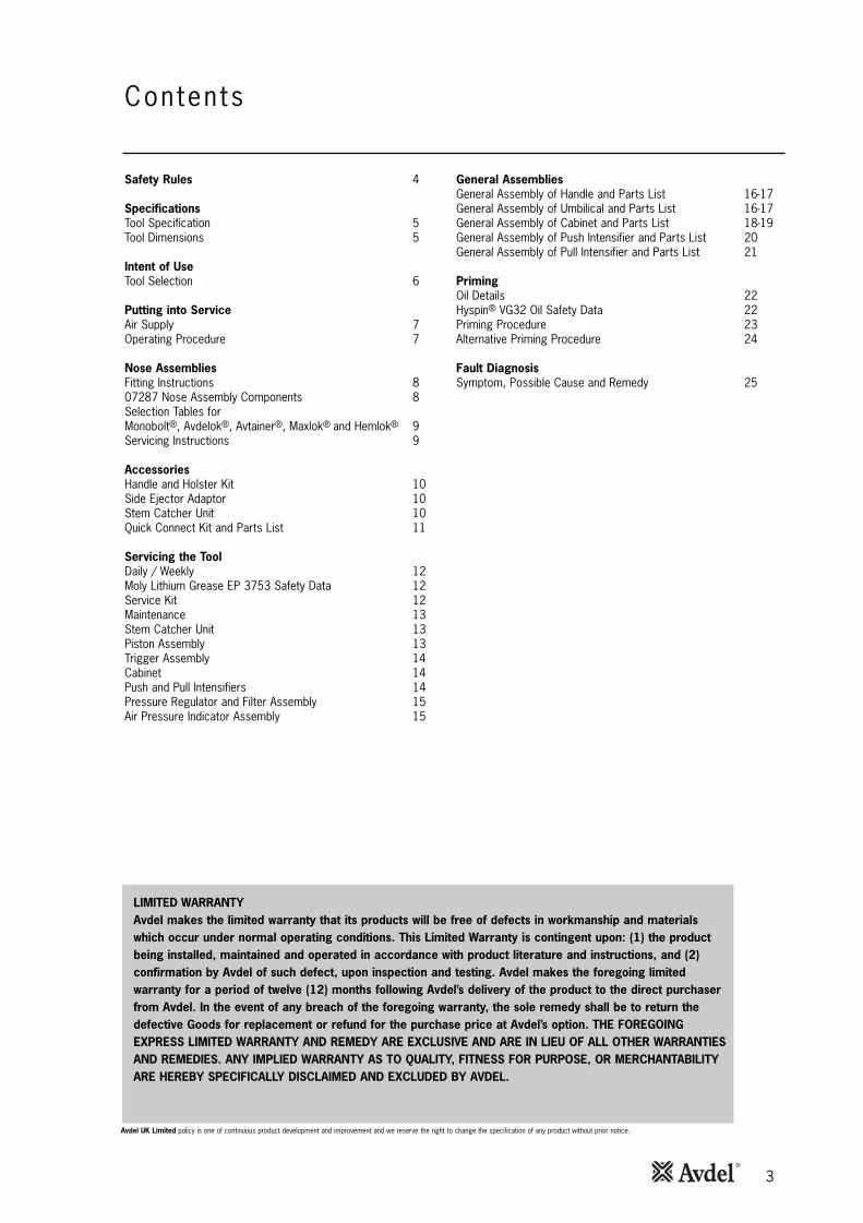
3
Safety Rules 4
SpecificationsTool Specification 5Tool Dimensions 5
Intent of UseTool Selection 6
Putting into ServiceAir Supply 7Operating Procedure 7
Nose AssembliesFitting Instructions 807287 Nose Assembly Components 8Selection Tables forMonobolt®, Avdelok®, Avtainer®, Maxlok® and Hemlok® 9Servicing Instructions 9
AccessoriesHandle and Holster Kit 10Side Ejector Adaptor 10Stem Catcher Unit 10Quick Connect Kit and Parts List 11
Servicing the ToolDaily / Weekly 12Moly Lithium Grease EP 3753 Safety Data 12Service Kit 12Maintenance 13Stem Catcher Unit 13Piston Assembly 13Trigger Assembly 14Cabinet 14Push and Pull Intensifiers 14Pressure Regulator and Filter Assembly 15Air Pressure Indicator Assembly 15
Contents
LIMITED WARRANTYAvdel makes the limited warranty that its products will be free of defects in workmanship and materialswhich occur under normal operating conditions. This Limited Warranty is contingent upon: (1) the productbeing installed, maintained and operated in accordance with product literature and instructions, and (2)confirmation by Avdel of such defect, upon inspection and testing. Avdel makes the foregoing limitedwarranty for a period of twelve (12) months following Avdel’s delivery of the product to the direct purchaserfrom Avdel. In the event of any breach of the foregoing warranty, the sole remedy shall be to return thedefective Goods for replacement or refund for the purchase price at Avdel’s option. THE FOREGOINGEXPRESS LIMITED WARRANTY AND REMEDY ARE EXCLUSIVE AND ARE IN LIEU OF ALL OTHER WARRANTIESAND REMEDIES. ANY IMPLIED WARRANTY AS TO QUALITY, FITNESS FOR PURPOSE, OR MERCHANTABILITYARE HEREBY SPECIFICALLY DISCLAIMED AND EXCLUDED BY AVDEL.
Avdel UK Limited policy is one of continuous product development and improvement and we reserve the right to change the specification of any product without prior notice.
General AssembliesGeneral Assembly of Handle and Parts List 16-17General Assembly of Umbilical and Parts List 16-17General Assembly of Cabinet and Parts List 18-19General Assembly of Push Intensifier and Parts List 20General Assembly of Pull Intensifier and Parts List 21
PrimingOil Details 22Hyspin® VG32 Oil Safety Data 22Priming Procedure 23Alternative Priming Procedure 24
Fault DiagnosisSymptom, Possible Cause and Remedy 25

4
Sa fe ty Ru les
1 Do not use outside the design intent.
2 Do not use equipment with this tool/machine other than that recommended and supplied by Avdel UK Limited.
3 Any modification undertaken by the customer to the tool/machine, nose assemblies, accessories or any equipment supplied by
Avdel UK Limited or their representatives, shall be the customer’s entire responsibility. Avdel UK Limited will be pleased to advise
upon any proposed modification.
4 The tool/machine must be maintained in a safe working condition at all times and examined at regular intervals for damage and
function by trained competent personnel. Any dismantling procedure shall be undertaken only by personnel trained in Avdel UK
Limited procedures. Do not dismantle this tool/machine without prior reference to the maintenance instructions. Please contact
Avdel UK Limited with your training requirements.
5 The tool/machine shall at all times be operated in accordance with relevant Health and Safety legislation. In the U.K. the “Health
and Safety at Work Act 1974” applies. Any question regarding the correct operation of the tool/machine and operator safety
should be directed to Avdel UK Limited.
6 The precautions to be observed when using this tool/machine must be explained by the customer to all operators.
7 Always disconnect the airline from the tool/machine inlet before attempting to adjust, fit or remove a nose assembly.
8 Do not operate a tool/machine that is directed towards any person(s) or the operator.
9 Always adopt a firm footing or a stable position before operating the tool/machine.
10 Ensure that vent holes do not become blocked or covered and that hoses are always in a good condition.
11 The operating pressure shall not exceed 7 bar.
12 Do not operate the tool if it is not fitted with a complete nose assembly unless specifically instructed otherwise.
13 Care shall be taken to ensure that spent stems are not allowed to create a hazard.
14 The tool must be fitted with an undamaged pintail deflector before operating.
15 When the tool is fitted with a stem deflector, it should be rotated until the aperture is facing way from the operator and other
person(s) working in the vicinity.
16 When using the tool, the wearing of safety glasses is required both by the operator and others in the vicinity to protect against
fastener ejection, should a fastener be placed ‘in air’. We recommend wearing gloves if there are sharp edges or corners on the
application.
17 Take care to avoid entanglement of loose clothes, ties, long hair, cleaning rags etc. in the moving parts of the tool which should
be kept dry and clean for best possible grip.
18 When carrying the tool from place to place keep hands away from the trigger/lever to avoid inadvertent start up.
19 Excessive contact with hydraulic fluid oil should be avoided. To minimize the possibility of rashes, care should be taken to wash
thoroughly.
20 C.O.S.H.H. data for all hydraulic oils and lubricants is available on request from your tool supplier.
This instruction manual must be read with particular attention to the following safety rules, by any personinstalling, operating, or servicing this tool.

5
Dimensions shown in bold are in millimetres.Other dimensions are in inches.
3000118.11
07267
652.5
63 Ø2.5 Ø
40 Ø1.6 Ø
1626.4
652.5
1706.7
50019.68
2509.84
40015.74
Air Pressure Minimum - Maximum 5-7 bar (72.5 - 101.5 psi)
Free Air Volume Required @ 5.5 bar (80 psi) 3.5 litres
Stroke Minimum Underload 29mm (1.14in)
Free Cycling 32mm (1.26in)
Pull Force @ 5.5 bar (80 psi) 32.4 kN
Cycle time Approximately 1.7 second
Noise Level 75 dB(A)
Pistol Weight (without nose equipment) 1.47 kg (3.23 lb)
Total Weight Pistol and Intensifier(without nose equipment) 40 kg (88 lb)
Vibration Less than 2.5 m/s2 (8.2 ft/s2)
Spec i f i ca t ions
Tool Spec i f icat ion
Too l D imens ions
6
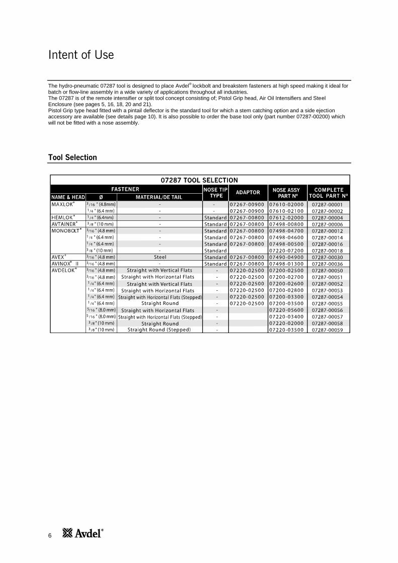
Intent of Use
The hydro-pneumatic 07287 tool is designed to place Avdel®
lockbolt and breakstem fasteners at high speed making it ideal for batch or flow-line assembly in a wide variety of applications throughout all industries. The 07287 is of the remote intensifier or split tool concept consisting of; Pistol Grip head, Air Oil Intensifiers and Steel Enclosure (see pages 5, 16, 18, 20 and 21). Pistol Grip type head fitted with a pintail deflector is the standard tool for which a stem catching option and a side ejection accessory are available (see details page 10). It is also possible to order the base tool only (part number 07287-00200) which will not be fitted with a nose assembly.
Tool Selection
7
All tools are operated with compressed air. The pressure regulator in the cabinet is set to an optimum pressure of 5.25 bar. Regardlessof the air inlet pressure, the pressure gauge in the cabinet will show 5.25 bar maximum. The pressure regulator in the cabinet must notbe adjusted under any circumstances. In addition, we recommend the use of external pressure regulators and automatic oiling/filteringsystems on the main air supply. These should be fitted within 3 metres of the tool (see diagram below) to ensure maximum tool life andminimum tool maintenance.
86
42
0
10121416
TAKE OFF POINTFROM MAIN SUPPLY
STOP COCK(USED DURING MAINTENANCE
OF FILTER/REGULATOR OR LUBRICATION UNITS)
MAIN SUPPLYDRAIN POINT
PRESSURE REGULATORAND FILTER
(DRAIN DAILY)
LUBRICATOR
3 M
ETRES
07267
Put t ing in to Serv iceAir Supp ly
Operat ing Procedure
OPTION 2
• Ensure that the correct nose equipment is fitted.
• Connect the tool to the air supply.
• Insert the fastener stem into the nose of the tool.
• Insert the tool with the fastener squarely into the prepared holeof the application.
• Fully operate the trigger. The tool cycle will ensure the fasteneris placed.
OPTION 1
• Ensure that the correct nose equipment is fitted.
• Connect the tool to the air supply.
• Insert the fastener body squarely into the prepared hole of theapplication.
• Apply the tool to the protuding fastener stem.
• Fully operate the trigger. The tool cycle will ensure the fasteneris placed.
Air supply hoses should have a minimum working effective pressure rating of 150% of the maximum pressure produced in the systemor 10 bar, whichever is the highest. Air hoses should be oil resistant, have an abrasion resistant exterior and should be armoured whereoperating conditions may result in hoses being damaged. All air hoses MUST have a minimum bore diameter of 6.4 mm or 1/4 inch.
Read servicing daily details page 12.
I M P O R T A N TThe pressure regulator in the cabinet is set to 5.25 bar.
The pressure regulator must not be adjusted under any circumstances.
I M P O R T A N TThe safety valve in the cabinet is set to 5.25 - 5.30 bar.
The safety valve must not be adjusted under any circumstances.

8
Nose Assembl ies
I M P O R T A N TThe air supply must be disconnected when fitting or removing nose assemblies unless specifically instructed
otherwise.
• Lightly coat the jaws with Molylithium grease.
• Drop Jaws 5 into Jaw Housing 4 or Chuck Collet 3, depending on whether you have a short or long nose assembly (see table
opposite for identification).
• Insert Jaw Spreader 7 into Jaw Housing 4 (locating in the ‘V’ shape formed by the jaws) or insert front Spring Guide 6 into Chuck
Collet 3.
• Locate Buffer 8 on Jaw Spreader 7.
• Locate Spring 9 onto Jaw Spreader 7 or onto Front Spring Guide 6.
• On long nose assemblies, screw Rear Spring Guide 10 into Chuck Collet 3.
• Fit Locking Ring 11 onto the end plug of the tool.
• Holding tool pointing down, screw on the assembled jaw housing or chuck collet onto the end plug and tighten with spanner.
• Screw Nose Tip 1 into Nose Casing 2.
• Place Nose Casing 2 over Jaw Housing 4 or Chuck Collet 3 and screw onto tool, tightening with spanner.
F i t t ing Ins t ruct ions
1 2 3 5 10 116 9
1 2 4 9 115 87
07287 Nose Assembly ComponentsThis table lists nose assemblies. Each nose assembly represents a unique assembly of components which can be ordered individually.Component numbers refer to the illustration above. We recommend some stock as items will need regular replacement. Read theNose Assemblies Servicing Instructions opposite carefully. All nose assemblies also include a locking ring 11 part number07340-00327.
It is essential that the correct nose assembly is fitted prior to operating the tool. By knowing your original complete tool part numberor the details of the fastener to be placed, you will be able to order a new complete nose assembly using the selection tables onpages 8 and 9.
NOSE ASSY 1 2 4 5 7 8 9
NOSE ASSY 1 2 3 5 6 9 1007498-00500 07497-03202 07498-00501 07498-00502 07497-03002* 07498-00507 07500-02005 07498-00503
07490-04900 07490-04400 07340-00306 07340-00304 07340-07502 07340-07503 07340-01503 07340-01502 07498-01300 07498-01400 07340-00306 07340-00304 07340-07502 07340-07503 07340-01503 07340-01502
07498-04600
07498-03202
07340-00306
07340-00304
07498-04501*
07498-04502
07498-03003
07100-04003 07498-04700
07498-04701 07340-00306
07498-04503
07498-04501*
07498-04900
07498-03003
07100-04003

17
Nose Assemblies
Selection Tables for Monobolt®, Avdelok®, Avtainer®, Maxlok® and Hemlok®
Service Instructions
Nose assemblies should be serviced at weekly intervals.
• Remove the complete nose assembly using the reverse procedure to the ‘Fitting instructions’.
• Any worn or damaged part should be replaced by a new part.
• Particularly check wear on jaws.
• Ensure Jaw Spreader 7 assembly tube (where fitted) or Front Spring Guide 6 is not distorted.
• Check Spring 9 is not distorted.
• Assemble according to fitting instructions. Item numbers in bold refer to the Nose Assembly drawing on page 8.

10
1 2
34
5
9
10
5
7
8
6
11
9
10
Handle and Ho ls ter K i t
Accessor ies
07265-09500 PARTS LISTITEM PART Nº DESCRIPTION QTY SPARES
1 07265-09501 RUBBER HANDLE 1 -2 07265-09502 TUBE WITH HOOK 1 -3 07265-09504 M5 BOLTS 2 -4 07265-09503 HOLSTER 1 -5 07265-09505 M5 NUTS 3 -6 07265-09508 BASE 1 -7 07265-09507 M5 BOLT 4 -8 07265-09506 M5 BOLT 1 -9 07265-09512 M5 BOLT 2 -
10 07265-09511 CLIPS 2 -11 07265-09509 PLATE 1 -
This kit enables an easier handling of the cabinet around theworkplace and allows the tool pistol to be stored in a convenientposition.
Side E ject ion Adaptor
When fitted between the tool and the nose assembly, this accessoryforces fastener stems to eject at the front of the tool. Choose thecorrect part number according to the stem diameter of the fastener.
Stem Catcher Un i t
Fitted to the rear of the tool, this unit catches the spent stems,preventing them fouling the work area. It should be emptiedwhen half full of spent stems.
07265-03800 PARTS LISTITEM PART Nº DESCRIPTION QTY SPARES
1 07267-01039 SCREW 3 -2 07265-02013 SCREW 2 -3 07640-00239 OUTER BODY 1 -4 07265-02054 FOAM SILENCER 1 -5 07340-00335 END CAP 1 -6 07640-00241 INNER BODY 1 -7 07498-00310 END COVER 1 -8 07267-01038 ADAPTOR 1 -
1
8
2
6
4
7
5
3

11
Quick Connect K i t
1
2 3 9
4
1
5
6*14
*157 *16
8
910
11
9
1213
2
6
5
Accessor ies
ITEM PART Nº DESCRIPTION QTY SPARES
07267-01250 PARTS LIST
1 07265-03206 NUT 4 -2 07265-03269 CONNECTION 4 -3 07265-03295 AIR HOSE EXTENSION 1 -4 07265-09296 OIL HOSE EXTENSION 2 -5 07265-03204 WASHER 4 -6 07265-03205 SCREW 4 -7 07265-03275 TRAY 1 -8 07267-01022 NIPPLE 2 -9 07265-02031 WASHER 6 -
10 07265-03278 QUICK FITTING NIPPLE 2 -11 07267-03277 QUICK FITTING COUPLER 2 -12 07265-03272 WASHER 1 -13 07265-03221 CONNECTOR 2 -
* 14 07267-03251 RUBBER RING 1 -* 15 07267-03252 SPACER WASHER 1 -* 16 07265-03292 CLAMP 1 -
* These items are part of the Base Tool and are not part of the QuickConnect Kit
This kit enables rapid connection of the handle and hose to the cabinet.
Par ts L is t o f Qu ick Connect K i t 07267-01250
12
• Dismantle and clean nose assembly, with special attention to the jaws. Lubricate with Moly Lithium grease EP 3753 beforeassembling.
• Check for oil leaks and air leaks in the air supply hose and fittings.
Grease can be ordered as a single item, the part number is shown in the Service Kit below.
First AidSKIN:As the grease is completely water resistant it is best removed with an approved emulsifying skin cleaner.INGESTION:Ensure the individual drinks 30ml Milk of Magnesia, preferably in a cup of milk. EYES:Irritant but not harmful. Irrigate with water and seek medical attention.FireFLASH POINT: Above 220°C.Not classified as flammable.Suitable extinguishing media: CO2, Halon or water spray if applied by an experienced operator.EnvironmentScrape up for burning or disposal on approved site.HandlingUse barrier cream or oil resistant glovesStorageAway from heat and oxidising agent.
For all servicing we recommend the use of the Service Kit, part number 07900-06270.
I M P O R T A N TRead Safety Instructions on page 4.
The employer is responsible for ensuring that tool maintenance instructions are given to the appropriate personnel.The operator should not be involved in maintenance or repair of the tool unless properly trained.
The tool shall be examined regularly for damage and malfunction.
Serv ic ing the Too l
Dai ly
Weekly
Moly L i th ium Grease EP 3753 Safety Data
• Daily, before use or when first putting the tool into service, pour a few drops of clean, light lubricating oil into the air inlet of thetool if no lubricator is fitted on air supply. If the tool is in continuous use, the air hose should be disconnected from the main airsupply and the tool lubricated every two to three hours.
• Check for air leaks. If damaged, hoses and couplings should be replaced by new items.
• If there is no filter on the pressure regulator, bleed the air line to clear it of accumulated dirt or water before connecting the air
hose to the tool. If there is a filter, drain it.
• Check that the nose equipment is correct.
• Check oil level in intensifier’s reservoir. If necessary top up with the prescribed priming oil.
Regular servicing should be carried out and a comprehensive inspection performed annually or every 500000 cycles, whichever issooner.
Serv ice K i t
ITEM PART Nº DESCRIPTION Nº OFF
07900-00589 SPREADER 107900-00590 PUSHER 107900-00591 BULLET 107900-00592 GAUGE 1
SERVICE KIT
13
Serv ic ing the Too lMaintenance
Stem Catcher Un i t
Item numbers in bold refer to the General Assembly and Parts List on pages 16 and 17.
• The airline must be disconnected before any servicing or dismantling is attempted unless specifically instructed otherwise.
• It is recommended that any dismantling operation be carried out in clean conditions.
• Prior to dismantling the tool it is necessary to remove the nose assembly. For simple removal instructions see the NoseAssemblies section on pages 8 and 9.
• Remove Bleed Screw 18 and Washer 19 from the tool handle and drain oil from tool.
• For total tool servicing we advise that you proceed with dismantling of sub-assemblies in the order shown overleaf.
• To disconnect Oil Hose 26 and Air Hose 27 from the tool handle, lower Sleeve 22 to gain access to the hoses.
• Disconnect air hose by pushing and releasing the quick release connector. Using two spanners, undo oil hose at Connector 21,leaving the connector attached to the tool handle. Remove the tool handle.
Item numbers in bold refer to the Stem Catcher Unit drawing on page 10.
• To remove the stem catcher assembly from the tool, loosen three Screws 1 and slide stem catcher Adaptor 8 together with thestem catcher from off of the Stop Cover 3* (*on pages 16 and 17).
• Remove two Screws 2 and separate the stem catcher assembly from stem catcher adaptor.
• Assemble in reverse order of dismantling.
Pis ton Assembly
Item numbers in bold refer to the General Assembly and Parts List on pages 16 and 17.
• Grip tool Handle 1 in a vice fitted with soft jaws and, using a spanner on the flats of the protrusion on Stop Cover 3, unscrewstop cover, together with ‘O’ Ring 12.
• Remove ‘O’ Ring 12 from groove on outer diameter of Stop Cover 3 and remove Seal 11 from inner diameter.
• Using circlip pliers, remove Circlip 17 from Piston 2 and withdraw Deflector Support 4 and Spring 5.
• Push Piston 2 out of rear of tool (some oil will be ejected from tool during this action).
• Using circlip pliers, remove Circlip 16 from tool handle and remove Lip Seal 10.
• Remove ‘O’ Ring 14 and Graphite Ring 13 from Piston 2.
• Assemble in reverse order of dismantling, ensuring that Seals 10, 11, 14 and Graphite Ring 13 are assembled the correct wayround as shown on page 16.
• Use piston insertion tool* to install the piston.
* Item included in the service kit.
I M P O R T A N TRead Safety Instructions on page 4.
The employer is responsible for ensuring that tool maintenance instructions are given to the appropriate personnel.The operator should not be involved in maintenance or repair of the tool unless properly trained.
The tool shall be examined regularly for damage and malfunction.
Every 500000 cycles the tool should be completely dismantled and new components should be used where worn, damaged orrecommended. All ‘O’ rings and seals should be renewed and lubricated with Moly Lithium grease EP 3753 before assembling.
14
I M P O R T A N T
Check the tool against daily and weekly servicingPriming is ALWAYS necessary after the tool has been dismantled and prior to operating.
Serv ic ing the Too lTr igger Assembly
Push and Pu l l In tens i f iers
Cabinet
Item numbers in bold refer to the General Assembly drawing and Parts List on pages 16-17.
• Using a spanner, undo Locknut 7 and remove Trigger 6, ‘O’ Ring 15, and Spring 8 from Handle 1.
• Assemble in reverse order of dismantling.
Item numbers in bold refer to the General Assembly drawing and Parts List on pages 18-19.
• The cabinet comprises two Intensifiers 4 and 25, a pilot Valve 23, a Pressure Regulator and Filter Assembly 45 and an AirPressure Indicating Assembly 53 together with the air hoses internal to the cabinet.
• Servicing is limited to removal/replacement of complete assemblies and the renewal of seals within the pilot valve.
• To dismantle the cabinet it is necessary to extract the Base Plate 61 and the components installed on it. This is possible afterdisconnecting all hoses and removing items restricting the withdrawal of the base plate.
Item numbers in bold refer to the General Assembly drawing and Parts List on pages 18-19.
• To remove Intensifiers 4, 25 and Oil Reservoir 36, disconnect the oil hose using two spanners, (be prepared for oil spillage fromhose/ intensifier), then remove the hoses (quick release connectors) connecting the intensifier to the pilot valve.
• Using a spanner, remove the two nuts and associated washers securing the intensifier to the baseplate.
• Lift intensifier clear of cabinet.
• Replacement is in reverse order of removal.

15
Item numbers in bold refer to the General Assembly drawing and Parts List on pages 18-19.
Serv ic ing the Too lPressure Regula tor and F i l ter Assembly
A i r Pressure Ind icator Assembly
• To remove the Pressure Regulator and Filter Assembly 45 from the cabinet, disconnect the two Air Hoses 59 and 63 at theregulator.
• Remove the two screws, spacers, washers and nuts securing the regulator to the cabinet.
• Remove assembly from the cabinet.
• Replacement is in reverse order of removal.
• To remove the Air Pressure Indicator Assembly 53, remove the air hose from the rear of the gauge.
• Remove the clamp from the rear of the gauge and withdraw gauge from front of the cabinet.
• Replacement is in reverse order of removal.
• After any dismantling/assembling has occurred, the system MUST be primed.
I M P O R T A N TThe pressure regulator in the cabinet is set to 5.25 bar.
The pressure regulator must not be adjusted under any circumstances.
I M P O R T A N TThe safety valve in the cabinet is set to 5.25 - 5.30 bar.
The safety valve must not be adjusted under any circumstances.

16
Genera l Assembly o f Hand le 07287-01000 andUmbi l i ca l 07287-01300
6
7
19
23
18
14
10
16
13
2
54
11
31
2
17
15
8
1
20
25
21
22
9
27
29
28
26
GEN
ERA
L A
SS
EMB
LY O
F U
MB
ILIC
AL
07
28
7-0
13
00
24

17
Parts List for 07287-01000 and 07287-01300
18
Genera l Assembly o f Cab inet 07287-03200
H
61
64
63
60
59
65
65
62
58
66
C
M
KM
J
G
B
M
B
A
M
E
D
F
L
14
A
4
5
6
7
1
9
10
2
2 313
8
11
12
B
15
1617
42
39
G
41
1142
11
40
4344
43
C22
1918
20
20
24 21
23
E29
30
31
28
32
33
36
35
34
H
20
46
45
4745
J
48
5049K
34 34
51
L
53
M
56
57
54
55
2714
D
25
16
1
910
2
2
13
26
11
12
17 F
3534
3534
1838 24
37
52
73
74
19
Par ts L is t o f Cab inet 07287-03200
07287-03200 CABINET PARTS LISTITEM PART Nº DESCRIPTION QTY SPARESITEM PART Nº DESCRIPTION QTY SPARES
1 07267-03224 SCREW 2 -2 07265-03259 WASHER 4 -3 07267-03227 DISTRIBUTOR 1 -4 07005-10112 INTENSIFIER 1 -5 07265-02267 BOLT 2 -6 07625-02268 WASHER 2 -7 07265-02269 NUT 2
8 07265-03260 CONNECTOR 1 -9 07265-03263 SILENCER 2 -
10 07265-03225 QUICK EXHAUST 2 -11 07265-03261 WASHER 5 -12 07267-03204 HOSE CONNECTOR 2 -13 07267-03226 ELBOW CONNECTOR 2 -14 07265-02031 WASHER 2 -15 07265-03202 HANDLE 2 -16 07265-02284 WASHER 6 -17 07265-02283 SCREW 4 -18 07267-03208 PLUG 2 -19 07265-03270 SILENCER 2 -20 07265-03271 STRAIGHT CONNECTOR 4 -21 07265-03222 SUB BASE 2 -22 07265-03266 SCREW 3 -23 07005-01524 VALVE 1 -24 07265-03268 WASHER 2 -25 07005-10113 INTENSIFIER 1 -26 07267-03221 CONNECTOR 1 -27 07267-03222 DISTRIBUTOR 1 -28 07267-03213 OIL RESERVOIR PLUG 1 -29 07267-03215 OIL RESERVOIR BASE 1 -30 07267-03219 NUT 2 -31 07267-03217 SPACER 2 -32 07267-03218 WASHER 2 -33 07267-03216 BOLT 2 -34 07267-03211 CLAMP 6 -35 07267-03210 HOSE CONNECTOR 4 -3637
07267-0321407267-03207
OIL RESERVOIROIL DISTRIBUTOR
11
--
38 07267-03209 CONNECTOR 1 -39 07267-03262 ELBOW CONNECTOR 2 -40 07267-03263 BUSH 1 -41 07267-03264 AIR TUBE 1 -42 07265-03253 CONNECTOR 2 -43 07265-02076 CLAMP 2 -44 07265-03219 AIR HOSE (2500mm) 1 -45 07265-03220 PRESSURE REG & FILTER ASSY 1 -46 07265-03256 ELBOW CONNECTOR 1 -47 07265-03257 ELBOW CONNECTOR 1 -48 07267-03251 RING 1 -49 07267-03252 WASHER 1 -50 07265-03292 CLAMP 1 -51 07267-03212 OIL FILTER 1 -52 07265-03255 ELBOW CONNECTOR 1 -53 07265-03254 AIR PRESSURE INDICATOR ASSY 1 -54 07265-03231 SCREW 4 -55 07265-03232 WASHER 4 -56 07265-03205 SCREW 8 -57 07265-03204 WASHER 8 -58 07265-03201 BOX (inc. KEY) 1 -59 07265-03216 6mm AIR HOSE (270mm) 1 -60 07265-03215 10mm AIR HOSE (100mm) 1 -61 07265-03230 BASE PLATE 1 -62 07265-03203 WHEEL 2 -63 07267-03268 10mm AIR HOSE (450mm) 3 -64 07265-03207 WHEEL 2 -65 07267-03265 OIL HOSE (400mm) 2 -66 07267-03266 OIL HOSE (200mm) 1 -
--
67 07267-03267 OIL HOSE 1 NOT SHOWN
68 07267-03271 10mm AIR HOSE 1 NOT SHOWN
69 07267-03272 6mm AIR HOSE 1 NOT SHOWN
70 07265-03272 WASHER 5 NOT SHOWN
71 07265-03273 WASHER 8 NOT SHOWN
727374
07265-0320607287-0328007287-03281
NUTSAFETY VALVE‘T’ CONNECTOR
811
NOT SHOW
-

20
Genera l Assembly o f Push In tens i f ie r 07005-10113
1
3
2
4 5 7 8 96 10 1211
14
13
15
16
17
19
20
24 25
21
22
23
18
Par ts L is t o f Push In tens i f ier 07005-10113
ITEM PART Nº DESCRIPTION QTY SPARES
1 07267-08119 SEAL 4 -2 07267-08104 SEAL 1 -3 07267-08107 FRONT FLANGE 1 -4 07267-08125 WASHER 4 -5 07267-08106 SCREW 4 -6 07287-08109 ROD 1 -7 07267-08134 SPRING 1 -8 07267-08133 SPRING GUIDE 1 - 9 07287-08117 PNEUMATIC CYLINDER 1 -10 07267-08110 PISTON 1 -11 07267-08031 WASHER 1 -12 07267-08112 SEAL 1 -13 07267-08113 BLIND NUT 8 -
07005-10113 PUSH INTENSIFIER PARTS LISTITEM PART Nº DESCRIPTION QTY SPARES
14 07267-08015 LOCKNUT 1 -15 07267-08116 REAR FLANGE 1 -16 07267-08130 ROD EXTENSION 1 -17 07287-08114 TENSION ROD 4 -18 07267-08126 SPRING WASHER 8 -19 07267-08122 FILTER 1 -20 07267-08103 SEAL 1 -21 07287-08102 STEEL HEAD 1 -22 07267-08128 WASHER 1 -23 07267-08101 PLUG 1 -24 07267-08123 WASHER 1 -25 07267-08121 BLEED SCREW 1 -26 07267-08135 FILTER 1 NOT SHOWN

21
Genera l Assembly o f Pu l l I n tens i f ie r 07005-10112
171819
16
15
14
12
13
11
1098743 65
2
1272625
24
23
22
21 20
Par ts L is t o f Pu l l In tens i f ier 07005-10112
07005-10112 PULL INTENSIFIER PARTS LISTITEM PART Nº DESCRIPTION QTY SPARESITEM PART Nº DESCRIPTION QTY SPARES
1 07267-08019 SEAL 4 -2 07287-08004 SEAL 1 -3 07267-08022 WASHER 4 -4 07267-08006 SCREW 4 -5 07287-08007 FRONT FLANGE 1 -6 07287-08017 PNEUMATIC CYLINDER 1 -7 07287-08008 SPRING 1 -8 07267-08010 PISTON 1 -9 07267-08011 PISTON SEAL 1 -10 07267-08012 SEAL 1 -11 07267-08020 SEAL 1 -12 07267-08031 WASHER 1 -13 07267-08015 LOCKNUT 1 -14 07267-08016 REAR FLANGE 1 -
15 07267-08035 SHOCK ABSORBER 1 -16 07267-08032 ROD EXTENSION 1 -17 07287-08014 TENSION ROD 4 -18 07267-08026 SPRING WASHER 8 -19 07267-08013 BLIND NUT 8 -20 07267-08033 FILTER 1 -21 07287-08009 ROD 1 -22 07287-08003 SEAL 1 -23 07287-08002 STEEL HEAD 1 -24 07267-08030 WASHER 1 -25 07267-08029 PLUG 1 -26 07267-08034 WASHER 1 -27 07267-08021 BLEED SCREW 1 -

22
Pr im ing
Oi l Deta i l s
Hysp in® VG32 Oi l Safety Data
Priming is ALWAYS necessary after the tool has been dismantled and prior to operating. It may also be necessary to restore the full strokeafter considerable use, when the stroke may be reduced and fasteners are not fully placed by one operation of the trigger.
The recommended oil for priming is Hyspin® VG32 available in 0.5l (part number 07992-00002) or one gallon containers (part number07992-00006). Please see safety data below.
First AidSKIN:Wash thoroughly with soap and water as soon as possible. Casual contact requires no immediate attention. Short term contactrequires no immediate attention.INGESTION:Seek medical attention immediately. DO NOT induce vomiting.EYES:Irrigate immediately with water for several minutes. Although NOT a primary irritant, minor irritation may occur following contact.
FireFlash point 232°C. Not classified as flammable.Suitable extinguishing media: CO2, dry powder, foam or water fog. DO NOT use water jets.
EnvironmentWASTE DISPOSAL: Through authorised contractor to a licensed site. May be incinerated. Used product may be sent for reclamation.SPILLAGE: Prevent entry into drains, sewers and water courses. Soak up with absorbent material.
HandlingWear eye protection, impervious gloves (e.g. of PVC) and a plastic apron. Use in well ventilated area.
StorageNo special precautions.

23
I M P O R T A N T
CONNECT AIR SUPPLY (this causes the piston to bottom, allowing more priming oil into the tool).DO NOT OPERATE THE TRIGGER WHILE THE BLEED SCREW IS REMOVED.
All operations should be carried out on a clean bench, with clean hands, in a clean area.Care MUST be taken, at all times, to ensure that no foreign matter enters the tool, or serious damage may result.
Pr im ingPr iming Procedure
Item numbers in bold refer to the General Assembly of Handle and Parts List on pages 16-17.
• Prior to starting the priming procedure, obtain a suitable container to collect excess oil.
• Disconnect the air supply and undo the intensifier oil reservoir cap.
• Top up the reservoir in the cabinet with VG32 Hyspin® priming oil to a level of 20 mm (0.8”) below top of the reservoir.
• Remove Bleed Screw 18 and associated Washer 19 from front of tool.
• Connect the tool to the air supply.
• CARE SHALL BE TAKEN TO ENSURE THAT THE BLEED HOLES ARE NOT DIRECTED TOWARDS THE OPERATOR OROTHER PERSONNEL.
• Place tool handle over the container with bleed hole orientated towards the container and operate the trigger.
• When oil is ejected from the bleed hole, release the trigger.
• Operate trigger again, replace Bleed Screw 18 and Washer 19 at front of tool BEFORE releasing trigger again.
• Disconnect tool from air supply.
• Remove Bleed Screw 18 and Washer 19 from rear of tool.
• Connect tool to air supply.
• Cycle the trigger until oil is ejected from the bleed hole. Release the trigger and replace the Bleed Screw 18 and Washer 19 at therear of the tool.
• Repeat the trigger operating/releasing sequence, allowing a few seconds between cycles to allow priming oil to circulate.
• Continue until oil flowing from both bleed holes is free of air bubbles, (ensure that the reservoir is not starved of oil, otherwise airwill be drawn into the system introducing air bubbles in the oil stream).
• When air free oil is flowing from both bleed holes, operate the trigger and tighten the front bleed screw with an Allen key. Releasethe trigger and tighten the rear bleed screw with an Allen key.
• If necessary, top up the oil reservoir.

24
I M P O R T A N T
CONNECT AIR SUPPLY (this causes the piston to bottom, allowing more priming oil into the tool).All operations should be carried out on a clean bench, with clean hands, in a clean area.
Care MUST be taken, at all times, to ensure that no foreign matter enters the tool, or serious damage may result.
Pr im ingAl ternat ive Pr iming Procedure
Item numbers in bold refer to the General Assembly of Handle and Parts List on pages 16 and 17, item number 28* refers to theGeneral Assembly of Cabinet and Parts List on pages 18 and 19.
• Prior to starting the priming procedure, obtain a suitable container to collect excess oil.
• Disconnect the air supply and undo the intensifier Oil Reservoir Plug 28*.
• Top up the reservoir in the cabinet with VG32 Hyspin® priming oil to a level of 20 mm (0.8”) below top of the reservoir.
If the oil hoses are changed, prime them before connecting, as follows:
• Disconnect the air supply.
• Place the oil tank in a higher position than the tool.
• In that position, unscrew the Bleed Screws 18 and Washers 19 until the oil flows under gravity.
• Once the oil starts to flow from one of the bleed holes, close it by tightening the screw. Wait until the oil flows from the other bleedhole, then close this as well.
In other cases, prime as below:
• CARE SHALL BE TAKEN TO ENSURE THAT THE BLEED HOLES ARE NOT DIRECTED TOWARDS THE OPERATOR OROTHER PERSONNEL.
• Connect the tool to the air supply.
• Keeping the trigger pressed, slightly loosen the Bleed Screw 18 (the closest to the front of the tool) until oil begins to flow.
• Keep the trigger pressed until there is no air in the oil, then tighten the Bleed Screw 18.
• Release the trigger.
• Repeat the last three steps, with intervals of several seconds, to ensure that clean oil circulates and all air is removed.
The hydraulic circuit for the pull side is now free of air. The following removes air from the hydraulic circuit on the return side.
• Keep the tool connected to the air.
• Without pressing the trigger (the return hydraulic circuit already has pressure), slightly loosen the Bleed Screw 18 from the rear ofthe tool until oil begins to flow.
• When there is no air in the oil, tighten the Bleed Screw 18.
• Operate trigger.
• Repeat the last three steps, with intervals of several seconds, to ensure that clean oil circulates and all air is removed.
Ensure that the oil reservoir is not starved of oil, otherwise air will be drawn in to the system.
• If necessary, refill the oil reservoir up to the level as indicated before.
To verify that the tool is correctly primed, measure the stroke. The piston stroke should be approximately 32mm and the piston shouldalways return fully.

Fau l t D iagnos is
Symptom Poss ib le Cause Remedy Page Ref
Several pulls Low air pressure Increase air pressure 7
required to set Lack of lubrication Lubricate tool at air inlet point 12
rivet Worn or broken jaws Fit new jaws 8
Oil level in tool low or air in oil Prime tool 22-24
Tool will not grip Worn or dirty jaws Clean or fit new jaws 8
stem of fastener Jaw housing loose Tighten against nylon locking ring 8
Weak or broken spring in nose assembly Fit new spring 8
Incorrect component in nose assembly Identify and replace 8
Tool fails to break Insufficient air pressure Adjust air pressure/air leaks 7
Lockbolt Incorrect length of bolt Change to correct length of bolt
Tool requires priming Reprime tool 22-24
Tool exhaust silencer dirty Clean silencer
Control valve dirty Remove/clean valve
Tool fails to swage Insufficient air pressure Adjust air pressure/air leaks 7
collar Warn anvils Replace
Tool requires priming Reprime tool 22-24
Swaging anvil cracked Replace
Incorrect length of bolt Change to correct length of bolt
Other symptoms or failures should be reported to your local Avdel® authorised distributor or repair centre.
25

26
Notes
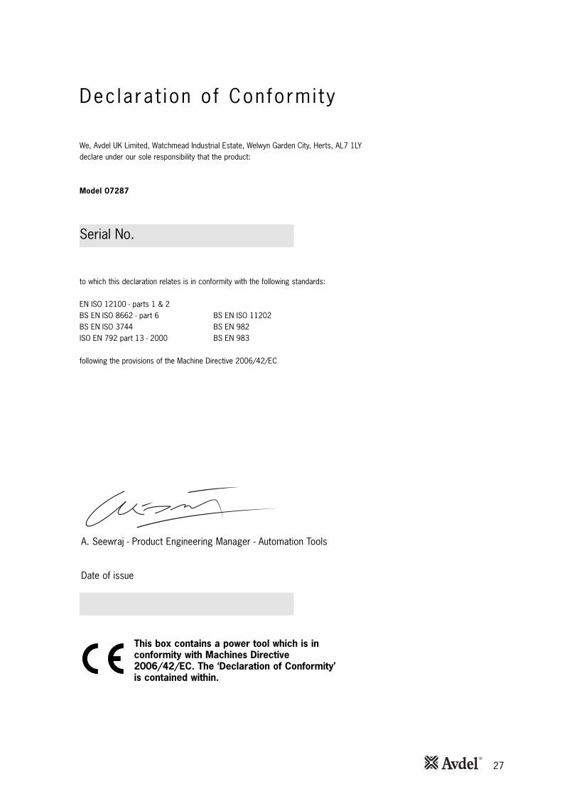
27
Dec lara t ion o f Conformi ty
We, Avdel UK Limited, Watchmead Industrial Estate, Welwyn Garden City, Herts, AL7 1LYdeclare under our sole responsibility that the product:
Model 07287
Serial No. ................................................
to which this declaration relates is in conformity with the following standards:
EN ISO 12100 - parts 1 & 2BS EN ISO 8662 - part 6 BS EN ISO 11202BS EN ISO 3744 BS EN 982ISO EN 792 part 13 - 2000 BS EN 983
following the provisions of the Machine Directive 2006/42/EC
This box contains a power tool which is inconformity with Machines Directive2006/42/EC. The ‘Declaration of Conformity’is contained within.
Date of issue
A. Seewraj - Product Engineering Manager - Automation Tools

Holding your world together®
Find your closest STANLEY Engineered Fastening location on www.StanleyEngineeredFastening.com/contact
For an authorized distributor nearby please check www.StanleyEngineeredFastening.com/econtact/distributors
Manual Number Issue C/N
07900-00918 B 14-147
www.StanleyEngineeredFastening.com
© 2013 Stanley Black & Decker, Inc., Rev. 01.2014
Avdel UK Limited Pacific House, 2 Swiftfields
Welwyn Garden City, Hertfordshire AL7 1LY Tel. +44 (0)1707 292-000 · Fax -199
Avbolt®, Avdel®, Avdelok®, Avex®, Avinox®, Avseal®, Avtainer®, Hemlok®, Maxlok® and Monobolt® are trademarks of Avdel UK Limited. The names and logos of other companies mentioned herein may be trademarks of their respective owners. Data shown is subject to change without prior notice as a result of continuous product development and improvement policy. Your local Avdel representative is at your disposal should you need to confirm latest information.