Traducción del manual original · 2017-02-02 · 4 instrucciones de seguridad avdel® recomienda...
49
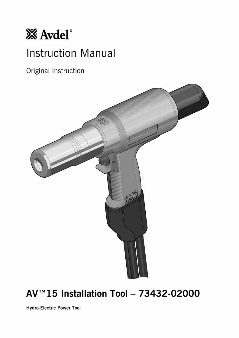
Manual de instrucciones Traducción del manual original Herramienta de instalación AV™15 – 73432-02000 Máquina hidroeléctrica
Transcript of Traducción del manual original · 2017-02-02 · 4 instrucciones de seguridad avdel® recomienda...

Manual de instrucciones
Traducción del manual original
Herramienta de instalación AV™15 –
73432-02000
Máquina hidroeléctrica

2
Contenido
Instrucciones de seguridad 3 - 4
Especificación 5 Uso previsto 5 Especificaciones de la herramienta de colocación 5 Dimensiones de la herramienta de colocación 6
Puesta en servicio 7 Principio de funcionamiento 7 Preparación para el uso 8 Instrucciones de funcionamiento 9
Mantenimiento de la herramienta 10 Diario / semanal / anualmente 10 Kit de servicio 10 Instrucciones de desmontaje 11
Montaje general de la herramienta de instalación 73432-02000 15 Montaje general 15 Lista de piezas 17
Datos de seguridad 18 Aceite hidráulico HF Enerpac
® - Datos de seguridad 18
Grasa MolyLithium EP3753 - Datos de seguridad 18 Grasa Molykote
® 111 -. Datos de seguridad 19
Diagnóstico de averías 20 Síntoma / Causa posible / Solución 20 - 22
Declaración de conformidad 24
GARANTÍA LIMITADA
Avdel ofrece la garantía limitada de que sus productos no presentarán defectos por mano de obra ni de material
en el marco de unas condiciones de funcionamiento normales. Esta garantía limitada está sujeta a: (1) la
instalación, el mantenimiento y el funcionamiento del producto de conformidad con las instrucciones y la
documentación técnica del producto y (2) la confirmación por parte de Avdel del defecto constatado tras una
inspección y comprobación. Avdel ofrece la anterior garantía limitada para un período de ciento ochenta (180)
días desde la entrega del producto de Avdel al comprador directo de Avdel. En caso de incumplimiento de la
garantía mencionada, la única vía de compensación será la devolución de los bienes defectuosos para su
sustitución o bien el reembolso por un precio de compra a discreción de Avdel. LA ANTERIOR GARANTÍA
LIMITADA EXPRESAMENTE Y LA COMPENSACIÓN SON EXCLUSIVAS Y PREVALECERÁN SOBRE OTRAS
GARANTÍAS Y COMPENSACIONES. POR LA PRESENTE, AVDEL EXCLUYE Y DECLINA ESPECÍFICAMENTE
TODA RESPONSABILIDAD RESPECTO A CUALQUIER GARANTÍA IMPLÍCITA RELATIVA A LA CALIDAD,
IDONEIDAD PARA EL FIN PREVISTO O CAPACIDAD DE COMERCIALIZACIÓN.
Avdel UK Limited sigue una política de desarrollo continuo, por lo que se reserva el derecho a modificar las especificaciones de
cualquier producto sin previo aviso.

3
Instrucciones de seguridad
El presente manual de instrucciones debe ser leído, prestando una atención especial a las siguientes normas de
seguridad, por cualquier persona que instale o maneje esta herramienta.
1 No utilice la máquina para otro propósito que no sea aquel para el que está diseñada.
2 No utilice esta herramienta/máquina con ningún otro equipo que no sea el recomendado y suministrado por
Avdel® UK Limited.
3 Cualquier modificación realizada por el cliente en la máquina será entera responsabilidad del cliente.
4 Antes de ajustar, extraer o encajar el conjunto de la boquilla, debe desconectarse siempre y totalmente la
herramienta de la unidad de bomba hidráulica.
5 No debe hacerse funcionar una herramienta/máquina que esté dirigida hacia cualquier persona o personas.
6 Debe adoptarse siempre una posición de apoyo firme y estable antes de hacer funcionar la máquina.
7 Cuando se utilice la máquina, se recomienda el uso de gafas de seguridad y auriculares protectores, tanto por
parte del operario como de cualquier persona que se encuentre en las proximidades.
8 No instale mangueras flexibles con una especificación de presión de trabajo inferior a 700 bar (10.000 psi).
9 Evite dañar las mangueras hidráulicas. A la hora de realizar el tendido de las mangueras hidráulicas, evite las
torsiones y curvas pronunciadas. El uso de mangueras dobladas o retorcidas conlleva contrapresiones graves.
Las curvas pronunciadas y torsiones dañan internamente la manguera y dan lugar a fallos prematuros en ésta.
10 No deje caer objetos pesados sobre las mangueras. Un fuerte impacto puede provocar daños internos en los
filamentos de alambre de la manguera y causarle fallos prematuros.
11 No levante la herramienta de colocación por las mangueras. Utilice siempre la empuñadura de la herramienta
de colocación.
12 No arrastre ni mueva la unidad de bomba hidráulica con ayuda de las mangueras. Utilice siempre la
empuñadura de la unidad de bomba o el arco de seguridad.
13 La presión de funcionamiento no debe exceder 550 bar (8000 psi).
14 Deben tomarse las precauciones debidas para asegurar que las colas usadas no supongan un peligro.
15 La herramienta debe llevar siempre incorporado un deflector de colas flexible que esté en buen estado.
16 Debe prestarse especial atención para evitar posibles atrapamientos de ropa, corbatas, cabellos, trapos, etc. con
las partes móviles de la máquina.
17 La herramienta deberá mantenerse seca y limpia para favorecer en lo posible el agarre.
18 Cuando se transporte la máquina de un emplazamiento a otro, las manos deben mantenerse alejadas del
disparador para evitar que se produzca un arranque inadvertido.
19 La máquina debe mantenerse en condiciones seguras de trabajo en todo momento y debe ser examinada a
intervalos regulares en cuanto a funcionalidad y existencia de posibles daños por personal con formación
adecuada. Cualquier operación de desmontaje será llevada a cabo exclusivamente por personal con formación
en los procedimientos de Avdel®. No desmonte esta máquina sin consultar previamente las instrucciones de
mantenimiento. Póngase en contacto con Avdel® si precisa formación.
20 La máquina debe utilizarse siempre conforme a la legislación de seguridad y salud vigente. En el Reino Unido
se aplica la "Health & Safety at Work etc Act 1974". Cualquier pregunta referente al funcionamiento correcto de
la máquina debe dirigirse a Avdel®.

4
Instrucciones de seguridad
AVDEL® RECOMIENDA QUE SOLAMENTE SE UTILICEN UNIDADES DE BOMBA HIDRÁULICA ENERPAC
®/AVDEL
®
PARA ACCIONAR HERRAMIENTAS DE INSTALACIÓN, DADO QUE LAS UNIDADES DE ACCIONAMIENTO
HIDRÁULICO DE OTRAS MARCAS PUEDEN NO FUNCIONAR A PRESIONES DE TRABAJO SEGURAS.
ANTES DE UTILIZAR LA HERRAMIENTA DEBE COMPROBARSE QUE HAYA UN ESPACIO ADECUADO PARA LAS
MANOS DEL OPERARIO.
NO DAÑE LA HERRAMIENTA DEJÁNDOLA CAER O UTILIZÁNDOLA COMO UN MARTILLO.
DEBE EVITARSE LA ENTRADA DE SUCIEDAD Y PARTÍCULAS EXTRAÑAS EN EL SISTEMA HIDRÁULICO DE LA
HERRAMIENTA, YA QUE ESTO PODRÍA CAUSAR UN FUNCIONAMIENTO INCORRECTO DE LA HERRAMIENTA Y
DE LA UNIDAD DE BOMBA.

5
Especificación
Uso previsto
La herramienta de instalación AV™15 es esencialmente un conjunto de un pistón y un cilindro. Una vez acoplada
eléctrica e hidráulicamente a una fuente de alimentación hidráulica compatible y fijado el conjunto de boquilla
correspondiente, se utiliza para instalar remaches Infalok® de 1/2” y remaches Avbolt
® de 1/2” en entornos industriales.
La herramienta de colocación y la unidad de bomba hidráulica deben utilizarse exclusivamente de conformidad con las
instrucciones de funcionamiento para la colocación de remaches de Avdel®.
Consulte la tabla siguiente para ver una lista de remaches aplicables y el equipo de boquilla asociado.
Consulte las hojas de datos enumeradas en la tabla para conocer las instrucciones del conjunto de boquilla
correspondiente.
REMACHE CONJUNTO DE BOQUILLA
HOJA DE DATOS DEL
CONJUNTO DE
BOQUILLA
TIPO TAMAÑO NÚMERO DE PIEZA DIM. "A" DIM. "B" NÚMERO DE PIEZA
AVBOLT® 1/2"
73432-03100 108 mm 43 mm 07900-00905
73433-03100* 108 mm 43 mm 07900-00905
INFALOK® 1/2"
73432-03200 107 mm 43 mm 07900-00919
73433-03200* 107 mm 43 mm 07900-00919
*Conjunto de boquilla con liberador de mordazas.
Consulte la ilustración de la página 6 para la identificación de las dimensiones "A" y "B" del conjunto de boquilla.
Las instrucciones de seguridad deben respetarse en todo momento.
Especificaciones de la herramienta de colocación
ESPECIFICACIÓN MÉTRICO IMPERIAL
Fuerza:
Tracción a la presión de tracción
especificada 80,0 kN 17984,7 lbf
Empuje hacia fuera a la presión de retorno
indicada 37,0 kN 8317,9 lbf
Presión:
Tracción 510 bar 7397 psi
Retorno 200 bar 2901 psi
Carrera: Carrera del pistón 32,0 mm 1,26"
Peso: Sin equipamiento de boquilla 4,5 kg 9,9 lb
Nivel de ruido: Menos de 80 dB(A)
Vibración: Menos de 2,5 m/s2 8 ft/s
2
Aceite hidráulico: Aceite hidráulico Enerpac®, HF-95X
Gama de producto:
Avbolt® 12,7 mm 1/2"
Infalok® 12,7 mm 1/2"
Características
adicionales:
Expulsión de vástagos, delante o detrás Detrás
Disposición de la junta Juntas de labio doble y rascadoras
Anillos de rodamiento hidráulico Sí, delante y detrás
Empuñadora de protección/manguera
Gator Sí
Protección para manguera Sí
Abrazaderas de retención de
cable/manguera Sí

6
Especificación
Dimensiones de la herramienta de colocación
246
66 134.5
46.5
87
B
A
222
Todas las dimensiones se muestran en milímetros.
Consulte la tabla de la página 5 para las dimensiones "A" y "B" del conjunto de boquilla.
La herramienta está equipada con dos mangueras hidráulicas y un cable de control eléctrico de 0,6 m de longitud.
Existen mangueras hidráulicas y alargadores de cable; pueden solicitarse por separado según sea necesario. Consulte la
tabla siguiente para conocer las longitudes de las mangueras disponibles y los números de pieza correspondientes.
MANGUERAS HIDRÁULICAS
NÚMERO DE PIEZA LONGITUD DE MANGUERA
07008-00448 5 metros
07008-00449 10 metros
07008-00450 15 metros

7
Puesta en servicio
Principio de funcionamiento
IMPORTANTE: LEA DETENIDAMENTE LAS INSTRUCCIONES DE SEGURIDAD EN LA PÁGINA 3 Y 4 Y EL MANUAL
DE INSTRUCCIONES DE LA UNIDAD DE BOMBA ANTES DE LA PUESTA EN SERVICIO
Cuando las mangueras y el cable de control están conectados a la unidad de bomba hidráulica Enerpac®/Avdel
®, los
ciclos de tracción y retorno de la herramienta se controlan pulsando y soltando el interruptor del disparador situado en la
empuñadura.
Cuando se pulsa el interruptor, la electroválvula situada en la unidad de bomba hidráulica se conecta y dirige el flujo de
aceite presurizado hacia el lado de tracción del pistón de la herramienta de colocación. Esto también permite que el
aceite que se encuentra en el lado de retorno de la herramienta de colocación regrese al depósito.
Durante los ciclos de tracción, el conjunto de pistón/aprietamordazas se mueve hacia la parte trasera de la herramienta,
lo que permite al cojín de tipo de junta tórica empujar el seguidor y la mordaza hacia delante. Si se ha insertado un
pasador de remache en el conjunto de boquilla, el juego de mordazas se sujeta con la cola, tras lo cual comienza el
montaje.
Para Avbolt® y Infalok
® el ciclo de colocación sujeta primero la junta que se vaya a remachar y luego, a medida que la
carcasa siga moviéndose hacia delante, el collar quedará comprimido en las ranuras de bloqueo del pasador. Al final del
ciclo de compresión, la carcasa queda comprimida contra la junta y, a medida que continúa el movimiento, se rompe la
cola.
El disparador debe soltarse inmediatamente después de que se produzca la rotura de un pasador. Al soltar el disparador
se desactiva la conexión de la electroválvula y se invierte el flujo del aceite presurizado.
Si no se suelta el disparador, el pistón de la herramienta de colocación continuará moviéndose hacia la parte trasera de
la herramienta hasta que alcance el final de su carrera. La presión en la zona de tracción aumentará hasta que se
alcance un valor de "alta presión" prefijado en la bomba. En este punto la electroválvula se desconecta automáticamente
e invierte el flujo del aceite presurizado al lado de retorno de la herramienta de colocación.
En cualquier caso, el aceite presurizado fluye ahora hacia el lado de retorno de la herramienta de colocación y el aceite
del lado de tracción regresa al depósito.
El movimiento de avance del conjunto de pistón/aprietamordazas expulsará el remache colocado de la carcasa.
En el momento de soltar el disparador o cuando se haya alcanzado el valor de "alta presión", la válvula eléctrica se
desconectará y activará un "contador de retorno" prefijado. Este contador controla el tiempo de funcionamiento del motor
de bomba antes de que se conmute al modo de reposo. El contador se puede ajustar manualmente entre 5 y 20
segundos para asegurarse de que el pistón de la herramienta de colocación siempre retorna completamente a la posición
de avance (consulte el manual de la bomba 07900-01030, páginas 10 y 13).
Cuando el pistón vuelva a la posición totalmente avanzada, la presión aumentará al valor de baja presión prefijado,
c200bar. El motor de la bomba continuará funcionando hasta que el contador de retorno haya finalizado. Después de
este intervalo de tiempo, el motor se detendrá automáticamente y la válvula conmutará a la posición de reposo. La
electroválvula pasará automáticamente a liberar el aceite presurizado a la reserva desde el lado de tracción y retorno de
la herramienta de colocación.
De este modo se mantiene la herramienta de colocación en la posición adelantada. No habrá presión en el sistema
hidráulico en este punto.
La unidad de bomba hidráulica arrancará automáticamente al pulsar el interruptor del disparador de la herramienta.
8
Puesta en servicio
Preparación para el uso
PELIGRO: LAS PRESIONES DE TRACCIÓN Y RETORNO CORRECTAS SON IMPORTANTES PARA GARANTIZAR UN
FUNCIONAMIENTO ADECUADO DE LA HERRAMIENTA DE COLOCACIÓN. SI LAS PRESIONES NO SON CORRECTAS
PUEDEN PRODUCIRSE DAÑOS PERSONALES O DAÑOS EN EL EQUIPO. LAS PRESIONES DE TRACCIÓN Y
RETORNO SUMINISTRADAS POR LA UNIDAD DE BOMBA HIDRÁULICA NO DEBEN SUPERAR LAS PRESIONES
QUE FIGURAN EN LAS ESPECIFICACIONES DE LA HERRAMIENTA DE COLOCACIÓN
IMPORTANTE: ANTES DE LA PUESTA EN SERVICIO DE LA HERRAMIENTA DE COLOCACIÓN Y DEL CONJUNTO DE
MANGUERAS HIDRÁULICAS:
ASEGÚRESE DE QUE LAS VÁLVULAS DE DESCARGA DE PRESIÓN DE LA BOMBA SE HAN AJUSTADO DE
CONFORMIDAD CON LAS INSTRUCCIONES DE LA BOMBA Y LAS PRESIONES MÁXIMAS ESPECIFICADAS PARA LA
HERRAMIENTA DE COLOCACIÓN Y LAS MANGUERAS.
ASEGÚRESE DE QUE EL KIT DE MANGUERAS SE HA CEBADO CON FLUIDO HIDRÁULICO DE CONFORMIDAD
CON EL PROCEDIMIENTO DESCRITO EN EL MANUAL DE INSTRUCCIONES DE LA BOMBA 07900-01030.
Asegúrese de que la fuente de alimentación eléctrica de la unidad de bomba hidráulica está desconectada.
Conecte los acopladores rápidos de manguera hidráulica de la herramienta de colocación directamente a la
unidad de bomba antes de conectar el cable de control eléctrico. Las mangueras y el cable de control se deben
conectar en este orden y desconectar en el orden inverso.
Conecte la fuente de alimentación eléctrica de la unidad de bomba hidráulica. Espere 5 segundos para que la
unidad de bomba finalice la secuencia de arranque antes de presionar el interruptor del disparador. Una vez
que esté todo configurado la pantalla LCD de la unidad de bomba mostrará "AVDEL".
Durante la secuencia de arranque el sistema de control de bomba identifica cualquier operación del disparador
como un fallo de funcionamiento potencial y evita que arranque el motor. La pantalla LCD mostrará "BUTTON
FAULT" (FALLO BOTÓN) en este caso. Para efectuar una reinicialización, desconecte el suministro de energía
durante 10 segundos.
Asegúrese de que la herramienta de colocación está colocada bajo los depósitos de reserva de bomba. Pulse y
suelte el interruptor de disparador de la herramienta de colocación varias veces hasta casi la longitud completa
de la carrera de la herramienta para que circule el fluido hidráulico y se expulse el aire de la herramienta.
Observe la acción de la herramienta. Compruebe si hay fugas de fluido y asegúrese de que, en el modo de
reposo, el pistón se encuentre en la posición completamente adelantada. La herramienta de colocación se
cebará.
Desconecte la fuente de alimentación eléctrica de la unidad de bomba hidráulica y seguidamente desconecte la
herramienta de colocación de la unidad de bomba en orden inverso al descrito anteriormente.
Conecte ahora la herramienta de colocación al kit de mangueras hidráulicas cebadas y al cable de control
eléctrico. A continuación, coloque los acopladores rápidos del kit de mangueras hidráulicas y el cable de control
eléctrico a la unidad de bomba.
Fije el conjunto de boquilla a la herramienta tal y como viene indicado en las instrucciones correspondientes de
la hoja de datos del conjunto de boquilla.
Conecte la fuente de alimentación eléctrica de la unidad de bomba hidráulica tal y como se describe
anteriormente.
Pulse y suelte el interruptor del disparador de la herramienta de colocación varias veces hasta casi la longitud
completa de la carrera de la herramienta para que circule el fluido hidráulico.
La herramienta de colocación está ahora lista para su uso.
9
Puesta en servicio
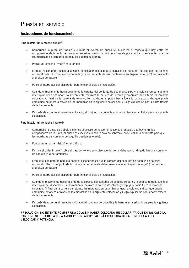
Instrucciones de funcionamiento
Para instalar un remache Avbolt®
Compruebe la pieza de trabajo y elimine el exceso de hueco (el hueco es el espacio que hay entre los
componentes de la junta; el hueco es excesivo cuando la cola no sobresale por el collar lo suficiente para que
las mordazas del conjunto de boquilla puedan sujetarla).
Ponga un remache Avbolt® en el orificio.
Empuje el conjunto de boquilla hacia el pasador hasta que la carcasa del conjunto de boquilla se detenga
contra el collar. El conjunto de boquilla y la herramienta deben mantenerse en ángulo recto (90°) con respecto
a la pieza de trabajo.
Pulse el interruptor del disparador para iniciar el ciclo de instalación.
Cuando el movimiento hacia delante de la carcasa del conjunto de boquilla se pare y la cola se rompa, suelte el
interruptor del disparador. La herramienta realizará la carrera de retorno y empujará hacia fuera el remache
colocado. Al final de la carrera de retorno, las mordazas empujan hacia fuera la cola expandida, que puede
empujarse entonces a través de las mordazas en la siguiente colocación y luego expulsarse por la parte trasera
de la herramienta.
Después de expulsar el remache colocado, el conjunto de boquilla y la herramienta están listos para la siguiente
colocación.
Para instalar un remache Infalok®
Compruebe la pieza de trabajo y elimine el exceso de hueco (el hueco es el espacio que hay entre los
componentes de la junta; el hueco es excesivo cuando la cola no sobresale por el collar lo suficiente para que
las mordazas del conjunto de boquilla puedan sujetarla).
Ponga un remache Infalok® en el orificio.
Deslice el collar Infalok® sobre el pasador (el extremo biselado del collar debe quedar dirigido hacia el conjunto
de boquilla y la herramienta).
Empuje el conjunto de boquilla hacia el pasador hasta que la carcasa del conjunto de boquilla se detenga
contra el collar. El conjunto de boquilla y la herramienta deben mantenerse en ángulo recto (90°) con respecto
a la pieza de trabajo.
Pulse el interruptor del disparador para iniciar el ciclo de instalación.
Cuando el movimiento hacia delante de la carcasa del conjunto de boquilla se pare y la cola se rompa, suelte el
interruptor del disparador. La herramienta realizará la carrera de retorno y empujará hacia fuera el remache
colocado. Al final de la carrera de retorno, las mordazas empujan hacia fuera la cola expandida, que puede
empujarse entonces a través de las mordazas en la siguiente colocación y luego expulsarse por la parte trasera
de la herramienta.
Después de expulsar el remache colocado, el conjunto de boquilla y la herramienta están listos para la siguiente
colocación.
PRECAUCIÓN: NO INTENTE ROMPER UNA COLA SIN HABER COLOCADO UN COLLAR, YA QUE EN TAL CASO LA
PARTE NO SEGURA DE LA COLA AVBOLT® O INFALOK
® SALDRÁ EXPULSADA DE LA BOQUILLA A ALTA
VELOCIDAD Y POTENCIA.

10
Mantenimiento de la herramienta
IMPORTANTE: LEA LAS INSTRUCCIONES DE SEGURIDAD DE LAS PÁGINAS 3 Y 4. EL EMPLEADOR DEBE
ASEGURARSE DE QUE SE PROPORCIONAN LAS INSTRUCCIONES DE MANTENIMIENTO DE LA HERRAMIENTA AL
PERSONAL ADECUADO. EL OPERARIO NO DEBE REALIZAR TAREAS DE MANTENIMIENTO O REPARACIÓN DE LA
HERRAMIENTA A MENOS QUE HAYA RECIBIDO UNA FORMACIÓN ESPECÍFICA AL RESPECTO. LA HERRAMIENTA
DEBE INSPECCIONARSE REGULARMENTE PARA DESCARTAR LA PRESENCIA DE DAÑOS Y FALLOS DE
FUNCIONAMIENTO.
Diario
Comprobar si la herramienta de colocación, las mangueras y los acopladores rápidos tienen fugas de aceite.
Las mangueras desgastadas o dañadas y los acoplamientos deben sustituirse.
Comprobar que la carrera de la herramienta cumple con las especificaciones.
Comprobar que el deflector de vástagos está instalado.
Comprobar que la válvula de descarga de presión de tracción/avance de la bomba funciona correctamente.
Comprobar la presencia de desgaste en la carcasa por medio de las marcas de abrasión en el collar instalado.
Esto también puede confirmarse consultando los datos instalados en el catálogo de remaches. Un desgaste
excesivo puede provocar la ruptura de la carcasa.
Semanal
Desmontar y limpiar el conjunto de boquilla, en particular, las mordazas tal y como viene descrito en la hoja de
datos del conjunto de boquilla.
Comprobar si la herramienta de colocación, las mangueras y los acopladores rápidos tienen fugas de aceite.
Anualmente o cada 250.000 operaciones
Cada 250.000 ciclos deberá desmontarse completamente la herramienta y deberán utilizarse nuevos
componentes si se constata la presencia de daños, desgaste o bien para cumplir con las recomendaciones
pertinentes. Todas las juntas tóricas, anillos de soporte y juntas deben sustituirse y lubricarse con grasa
MolyKote® 111 antes de proceder al montaje correspondiente.
Kit de servicio
Para un servicio completo se encuentra disponible el siguiente kit de servicio:
KIT DE SERVICIO: 73432-99990
NÚMERO DE PIEZA DESCRIPCIÓN NÚMERO DE PIEZA DESCRIPCIÓN
07005-10118 Acoplador rápido macho 07900-00966 Manguito guía del pistón AV15
07005-10120 Acoplador rápido hembra 07900-00967 Herramienta de conjunto de tapa
terminal AV15
07900-00961 Bala de pistón AV15, parte
delantera 07992-00020 Grasa MolyLithium EP3753
07900-00962 Bala de pistón AV15, parte trasera 07900-00755 Grasa Molykote® 111
07900-00965 Vástago guía del casquillo delantero
AV15 07900-00756 Bloqueador de roscas Loctite
® 243
Se precisan también las siguientes herramientas estándar:
Llave Allen: 2,0/3,0 mm
Llave plana de extremo abierto: 12 / 14 / 18 / 24 / 45 mm A/F
Cinta PTFE: 10 mm
Tornillo de banco con protectores de mordaza, 150 mm

11
Mantenimiento de la herramienta
Utilice exclusivamente aceite hidráulico Enerpac® HF. El uso de otro tipo de aceites puede causar fallos de
funcionamiento en la herramienta de colocación y la bomba y conllevará la anulación de la garantía de la herramienta de
colocación. El aceite hidráulico se puede solicitar mediante los siguientes números de pieza.
ACEITE HIDRÁULICO
NÚMERO DE PIEZA 07992-00081 07992-00082 07992-00083
Número de pieza Enerpac® HF-95X HF-95Y HF-95T
Volumen 1 litro 5 litros 20 litros
Viscosidad 32 mm2/s 32 mm
2/s 32 mm
2/s
Instrucciones de desmontaje
IMPORTANTE: ASEGÚRESE DE QUE LA FUENTE DE ALIMENTACIÓN ELÉCTRICA DE LA UNIDAD DE BOMBA
HIDRÁULICA ESTÁ DESCONECTADA ANTES DE QUITAR EL CONJUNTO DE BOQUILLA O DESMONTAR LA
HERRAMIENTA DE COLOCACIÓN.
Antes del desmontaje:
Desacople los acopladores rápidos 10 y 11 y el cable de control eléctrico 14 entre la herramienta de colocación
y el conjunto de manguera hidráulica.
Retire el conjunto de boquilla de la herramienta de colocación tal y como viene indicado en las instrucciones
correspondientes de la hoja de datos del conjunto de boquilla.
Para un servicio completo de la herramienta, recomendamos que efectúe el desmontaje de la herramienta en el orden
indicado en las páginas 11 a 14. Una vez desmontada la herramienta, recomendamos sustituir todas las juntas.
Todos los números en negrita hacen referencia a la lista general de conjuntos y piezas en las páginas 15, 16 y 17.
Conjunto del pistón del cabezal:
Utilice un destornillador plano pequeño, extraiga el pasador 41 del adaptador del aprietamordazas 40.
Desatornille y extraiga el adaptador del aprietamordazas 40 del pistón 1.
Retire el deflector 3 de la tapa terminal 17.
Sujete la empuñadura de la herramienta en un tornillo de banco con mordazas blandas de manera que la
boquilla de la herramienta mire hacia abajo. Inserte los pasadores de espiga en la *herramienta de conjunto de
tapa terminal en los tres orificios en la tapa terminal 17.
Utilice una llave tipo A/F de 24 mm para desatornillar y extraer la tapa terminal 17 del cuerpo 2.
Utilice un destornillador plano pequeño para extraer la junta tórica 21 de la tapa terminal 17 y deséchela.
Conecte el *acoplador rápido macho al acoplador rápido hembra 11 en la manguera hidráulica de retorno 18.
De este modo se liberará cualquier presión del lado de retorno del pistón y se facilita así la extracción del
casquillo de junta trasero 16.
Inserte tres tornillos M4 en el casquillo de junta trasero 16 y utilícelos para extraer la pieza del eje trasero del
pistón 1 y extraerla del cuerpo 2.
Utilice un destornillador plano pequeño o una herramienta similar para extraer la junta tórica 30 y el anillo de
soporte en espiral 36 de la ranura externa en el casquillo de junta trasero 16. Deseche estos dos componentes.
A la hora de extraer las juntas, proceda con sumo cuidado para no dañar la superficie del casquillo de junta
trasero con el destornillador.
Retire la junta de vástago 28 y la junta rascadora 31 de las ranuras internas en el casquillo de junta trasero 16.
Deseche estos componentes. A la hora de extraer las juntas, proceda con sumo cuidado para no dañar la
superficie del casquillo de junta trasero con el destornillador.
Todos los números en negrita hacen referencia a la lista general de conjuntos y piezas de las páginas 15, 16 y 17.
* Kit de servicio en la página 10

12
Mantenimiento de la herramienta
Retire el anillo de rodamiento trasero 29 y compruebe si la pieza se ha desgastado o dañado. Deséchela en
caso necesario.
Retire la herramienta de colocación del tornillo de banco y vacíe el aceite hidráulico de la parte trasera de la
herramienta. Retire el *acoplador rápido macho del acoplador rápido hembra 11.
Conecte el *acoplador rápido hembra al acoplador rápido macho 10 en la manguera hidráulica de tracción 19.
De este modo se liberará cualquier presión del lado de tracción del pistón 1 y se facilita así la extracción del
pistón.
Atornille la *bala de pistón, parte delantera, en la parte delantera del pistón 1.
Coloque la boquilla del cuerpo 2 boca arriba en un banco. A continuación, golpee con un mazo suave el pistón
1 hacia la parte trasera del cuerpo y fuera del extremo trasero procurando no dañar el orificio en el cuerpo.
Tenga en cuenta que al extraer el pistón 1, saldrá aceite en el lado de tracción del pistón por la parte delantera
y trasera del cuerpo 2.
Al extraer el pistón 1, el casquillo de junta delantero 15 puede retenerse en el eje del pistón. Si éste es el caso,
desatornille la *bala de pistón, parte delantera, y extraiga el casquillo de junta delantero del pistón.
Utilice un destornillador plano pequeño para retirar la junta de pistón 26 y los dos anillos antiextrusión 27 de la
ranura externa del pistón 1, y deséchelos. A la hora de extraer las juntas, proceda con sumo cuidado para no
dañar la superficie del pistón con el destornillador.
Si el casquillo de junta delantero 15 todavía está retenido en el cuerpo 2. Coloque el cuerpo con la boquilla
hacia arriba en un banco y empuje el casquillo de junta frontal de la parte frontal hasta que quede libre del
rebaje en el cuerpo. El casquillo de junta delantero puede extraerse del extremo trasero del cuerpo. Al hacerlo,
procure no dañar el taladro en el cuerpo.
Utilice un destornillador plano pequeño para extraer la junta tórica 23 y el anillo de soporte en espiral 34 de la
ranura externa en el casquillo de junta frontal 15 y deséchelos. A la hora de extraer las juntas, proceda con
sumo cuidado para no dañar la superficie del casquillo de junta trasero con el destornillador.
Retire la junta de vástago 25 y la junta rascadora 22 de las ranuras internas en el casquillo de junta frontal 15
y deséchelas. A la hora de extraer las juntas, proceda con sumo cuidado para no dañar la superficie del
casquillo de junta trasero con el destornillador.
Retire el anillo de rodamiento delantero 24 y compruebe si la pieza se ha desgastado o dañado. Deséchela en
caso necesario.
Utilice un destornillador plano pequeño para extraer la junta tórica 21 del cuerpo 2 y deséchela.
Retire el *acoplador rápido hembra del acoplador rápido macho 10 en la manguera hidráulica de tracción 19.
No extraiga el tornillo de ajuste 42 del cuerpo 2.
Realice el montaje en orden inverso al desmontaje teniendo en cuenta los siguientes puntos:
Limpie todos los componentes antes de proceder al montaje.
Para facilitar el montaje de las juntas aplique una ligera capa de grasa Molykote® 111 en todas las juntas,
ranuras de junta, anillos de soporte y herramientas de montaje.
Deslice la junta tórica 23 sobre el casquillo de junta delantero 15 y en la ranura externa. Inserte el anillo de
soporte en espiral 34 en la misma ranura, delante de la junta tórica instalada. Consulte la lista general de
conjuntos y piezas para la orientación correcta de la junta tórica y el anillo de soporte en espiral.
Todos los números en negrita hacen referencia a la lista general de conjuntos y piezas de las páginas 15, 16 y 17.
* Kit de servicio en la página 10
13
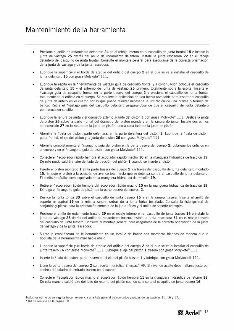
Mantenimiento de la herramienta
Presione el anillo de rodamiento delantero 24 en el rebaje interno en el casquillo de junta frontal 15 e instale la
junta de vástago 25 detrás del anillo de rodamiento delantero. Instale la junta rascadora 22 en el rebaje
delantero del casquillo de junta frontal. Consulte el montaje general para asegurarse de la correcta orientación
de la junta de vástago y de la junta rascadora.
Lubrique la superficie y el borde de ataque del orificio del cuerpo 2 en el que se va a instalar el casquillo de
junta delantero 15 con grasa Molykote® 111.
Lubrique la espita en la *herramienta de vástago guía de casquillo frontal y a continuación coloque el casquillo
de junta delantero 15 y el extremo de junta de vástago 25 primero, totalmente sobre la espita. Inserte el
*vástago guía de casquillo frontal en la parte trasera del cuerpo 2 y presione el casquillo de junta frontal
totalmente en el orificio en el cuerpo. Se requiere la aplicación de una fuerza razonable para insertar el casquillo
de junta delantero en el cuerpo por lo que puede resultar necesaria la utilización de una prensa o tornillo de
banco. Retire el *vástago guía del casquillo delantero asegurándose de que el casquillo de junta delantero
permanece en su sitio.
Lubrique la ranura de junta y el diámetro externo grande del pistón 1 con grasa Molykote® 111. Deslice la junta
de pistón 26 sobre la parte frontal del diámetro del pistón grande y en la ranura de junta. Instale dos anillos
antiextrusión 27 en la ranura de la junta de pistón, uno a cada lado de la junta de pistón.
Atornille la *bala de pistón, parte delantera, en la parte delantera del pistón 1. Lubrique la *bala de pistón,
parte frontal, el eje del pistón y la junta del pistón 26 con grasa Molykote® 111.
Atornille completamente el *manguito guía del pistón en la parte trasera del cuerpo 2. Lubrique los orificios en
el cuerpo y en el *manguito guía de pistón con grasa Molykote® 111.
Conecte el *acoplador rápido hembra al acoplador rápido macho 10 en la manguera hidráulica de tracción 19.
De este modo saldrá el aire del lado de tracción del pistón 1 cuando se inserte el pistón.
Inserte el pistón montado 1 en la parte trasera del cuerpo 2 y a través del casquillo de junta delantero montado
15. Empuje el pistón a la posición de avance total hasta que se detenga contra el casquillo de junta delantero.
El aceite hidráulico será expulsado de la manguera hidráulica de tracción 19.
Retire el *acoplador rápido hembra del acoplador rápido macho 10 en la manguera hidráulica de tracción 19.
Extraiga el *manguito guía de pistón de la parte trasera del cuerpo 2.
Deslice la junta tórica 30 sobre el casquillo de junta trasero 16 y en la ranura trasera. Inserte el anillo de
soporte en espiral 36 en la misma ranura, detrás de la junta tórica instalada. Consulte la lista general de
conjuntos y piezas para la orientación correcta de la junta tórica y el anillo de soporte en espiral.
Presione el anillo de rodamiento trasero 29 en el rebaje interno en el casquillo de junta trasero 16 e instale la
junta de vástago 28 detrás del anillo de rodamiento trasero. Instale la junta rascadora 31 en el rebaje trasero
del casquillo de junta trasero. Consulte el montaje general para asegurarse de la correcta orientación de la junta
de vástago y de la junta rascadora.
Sujete la empuñadura de la herramienta en un tornillo de banco con mordazas blandas de manera que la
boquilla de la herramienta mire hacia abajo.
Lubrique la superficie y el borde de ataque del orificio del cuerpo 2 en el que se va a instalar el casquillo de
junta trasero 16 con grasa Molykote® 111. Lubrique el eje del pistón 1 trasero con grasa Molykote
® 111.
Inserte la *bala de pistón, parte trasera en el eje del pistón trasero 1 y lubrique con grasa Molykote® 111.
Llene la parte trasera del cuerpo 2 con aceite hidráulico Enerpac® HF. El nivel de aceite debe hallarse justo por
encima del taladro de entrada trasero en el cuerpo.
Conecte el *acoplador rápido macho al acoplador rápido hembra 11 en la manguera hidráulica de retorno 18.
De esta manera saldrá aire del lado de retorno del pistón cuando se inserte el casquillo de junta trasero 16.
Todos los números en negrita hacen referencia a la lista general de conjuntos y piezas de las páginas 15, 16 y 17.
* Kit de servicio en la página 10

14
Mantenimiento de la herramienta
Coloque el casquillo de junta trasero 16 sobre la *bala de pistón, parte trasera. A continuación, presione el
casquillo de junta trasero sobre el eje del pistón 1 y en la parte trasera del cuerpo 2. Empuje el casquillo de
junta trasero en el cuerpo hasta que se muestren varias roscas internas en la parte trasera del cuerpo. Procure
no dañar la junta tórica 30 ni el anillo de soporte en espiral 36 en las roscas cuando inserte el casquillo de
junta trasero.
Lubrique con grasa MolyLithium la rosca interna en el cuerpo 2 y la rosca externa en la tapa terminal 17.
Atornille totalmente la tapa terminal 17 en la parte trasera del cuerpo 2 con ayuda de la *herramienta de
montaje de la tapa terminal. Al hacerlo, el casquillo de junta trasero 16 quedará presionado en posición dentro
del cuerpo y saldrá una pequeña cantidad de aceite de la manguera hidráulica de retorno 18.
Retire el *acoplador rápido macho del acoplador rápido hembra 11 en la manguera hidráulica de retorno 18.
Presione el deflector 3 en la tapa terminal 17.
Atornille el adaptador de aprietamordazas 40 en el pistón 1 hasta que la parte delantera quede alineada con el
extremo del pistón. Alinee el orificio en el adaptador del aprietamordazas con la ranura en el extremo del pistón
y, a continuación, inserte el pasador de bloqueo 41.
Cebe la herramienta de colocación tal y como viene descrito en el apartado Preparativos para el uso de la
página 8.
Conjunto de mangueras:
Extraiga los dos tornillos 9 de la abrazadera de manguera 13 con ayuda de una llave Allen de 3,0 mm. Extraiga
la abrazadera de manguera y la inserción de abrazadera 20 del manguito protector 37 y las mangueras
hidráulicas 18 y 19.
Utilice un destornillador plano pequeño para separar la empuñadura Gator 8 de la empuñadura del cuerpo 2.
Tire de la empuñadura Gator sobre el manguito protector 37, mangueras hidráulicas 18 y 19 proceda a la
extracción.
Corte el abrazacables 35 y deslice hacia detrás la manguera protectora 37 para mostrar los racores en las
mangueras hidráulicas 18 y 19. Las mangueras hidráulicas se pueden extraer del cuerpo 2 con ayuda de llaves
de 12 y 14 mm.
Los acopladores rápidos 10 y 11 pueden extraerse de las mangueras hidráulicas 18 y 19 con ayuda de llaves
de 18 y 24 mm.
Para extraer el interruptor del disparador 7, suelte primero el casquillo de cable 38, de manera que el cable de
control 14 quede con libertad de movimientos en el cuerpo 2. A continuación, afloje el tornillo de ajuste M4 12
con ayuda de una llave Allen de 2,0 mm.
Presione el cable de control 14 en el cuerpo 2 y simultáneamente extraiga el interruptor del disparador 7 del
cuerpo para mostrar las juntas de soldadura de los terminales del interruptor del disparador. Desuelde los
terminales para extraer el interruptor del disparador y la inserción del disparador 39. La inserción del disparador
está unida al interruptor del disparador y no puede extraerse.
El cable de control 14 puede extraerse ahora del cuerpo 2 y retirarse del manguito de protección 37.
Realice el montaje en orden inverso al desmontaje teniendo en cuenta los siguientes puntos:
Antes de proceder al montaje, limpie todas las roscas de los acopladores rápidos macho 10 y hembra 11 y las
mangueras hidráulicas de retorno 18 y tracción 19. Aplique de 2 a 3 capas de cinta PTFE de 10 mm en las
roscas macho en las dos mangueras hidráulicas.
Al sustituir el interruptor del disparador 7 aplique Loctite® 243 en la rosca macho del interruptor del disparador
antes de montar la inserción del disparador 39.
Aplique *Loctite® 243 en el tornillo de ajuste M4 12 antes del montaje.
Una vez montado, cebe la herramienta conforme a las instrucciones que figuran en la página 8.
Todos los números en negrita hacen referencia a la lista general de conjuntos y piezas de las páginas 15, 16 y 17.
* Kit de servicio en la página 10

15
Montaje general de la herramienta de instalación
73432-02000
3 4, 2 5 40
7
8
12
1
9
10
11
13
14

16
Montaje general de la herramienta de instalación
73432-02000
21 22 34 23 24 25 26 27
39
28 29 30 36 31 21
35
37
38
DETAIL B
DETAIL C
DETAIL D
DETAIL E
42
DETAIL F
41 15 1 17
E
D
18
19
16
B
C
F
20
DETALLE B
DETALLE C
DETALLE D
DETALLE E
DETALLE F

17
Lista de piezas de la herramienta de instalación
73432-02000
Lista de piezas 73432-02000
ARTÍCULO NÚMERO DE PIEZA DESCRIPCIÓN CANTIDAD
1 73432-02003 PISTÓN 1
2 73432-02001 CUERPO 1
3 73432-02011 DEFLECTOR 1
4 73430-02025 ETIQUETA DE SEGURIDAD 1
5 73432-02026 ETIQUETA AV15 2
6
7 07007-02103 INTERRUPTOR DEL DISPARADOR 1
8 73430-02020 EMPUÑADURA GATOR 1
9 07001-00686 TORNILLO HD HEXAGONAL M4 X 16 2
10 07005-10118 ACOPLADOR RÁPIDO MACHO 1
11 07005-10120 ACOPLADOR RÁPIDO HEMBRA 1
12 07001-00479 TORNILLO DE AJUSTE HEXAGONAL M4 X 4 1
13 73430-02023 ABRAZADERA DE MANGUERA 1
14 07007-02105 CABLE DE CONTROL 1
15 73432-02004 CASQUILLO DE JUNTA DELANTERO 1
16 73432-02006 CASQUILLO DE JUNTA TRASERO 1
17 73432-02005 TAPA TERMINAL 1
18 07005-10119 MANGUERA HIDRÁULICA DE RETORNO 1
19 07005-10117 MANGUERA HIDRÁULICA DE TRACCIÓN 1
20 73430-02024 INSERCIÓN DE ABRAZADERA 1
21 07003-00460 JUNTA TÓRICA 2
22 07003-00446 JUNTA RASCADORA 1
23 07003-00459 JUNTA TÓRICA 1
24 73432-02009 ANILLO DE RODAMIENTO DELANTERO 1
25 07003-00445 JUNTA DE VÁSTAGO 1
26 07003-00449 JUNTA DE PISTÓN 1
27 07003-00450 ANILLO ANTIEXTRUSIÓN 2
28 07003-00447 JUNTA DE VÁSTAGO 1
29 73432-02010 ANILLO DE RODAMIENTO TRASERO 1
30 07003-00462 JUNTA TÓRICA 1
31 07003-00448 JUNTA RASCADORA 1
32
33
34 07003-00493 ANILLO DE SOPORTE EN ESPIRAL 1
35 07007-02032 ABRAZADERA PARA CABLE 1
36 07003-00495 ANILLO DE SOPORTE EN ESPIRAL 1
37 07005-10121 MANGUITO PROTECTOR 0,6 m
38 07007-02104 CASQUILLO PARA CABLE 1
39 73430-02008 INSERCIÓN DEL DISPARADOR 1
40 73432-02012 ADAPTADOR DEL APRIETAMORDAZAS, AV15 1
41 73432-02013 PASADOR DE BLOQUEO, AV15 1
42 07001-00481 TORNILLO DE AJUSTE HEXAGONAL M5 X 5 1
- 07900-01021 MANUAL DE INSTRUCCIONES DE LA HERRAMIENTA AV15 1

18
Datos de seguridad
Aceite hidráulico HF Enerpac®
- Datos de seguridad
PRIMEROS AUXILIOS
PIEL:
Es poco probable que cause daños en la piel con un contacto breve u ocasional, pero un uso o exposición prolongada
puede causar dermatitis. Lave minuciosamente la piel con agua y jabón en la medida de lo posible. Quítese la ropa que
haya estado expuesta a una contaminación considerable y lávese la piel.
INGESTIÓN:
Es poco probable que cause daños en caso de ingestión accidental en pequeñas dosis; en caso de cantidades grandes
puede provocar náuseas y diarrea. Si la boca queda expuesta a una contaminación, deberá enjuagarse bien con agua.
Excepto en caso de una acción deliberada, la ingestión de grandes volúmenes de producto es poco probable. Si se diera
el caso, no provocar el vómito; acudir al médico. Lleve a la persona accidentada al centro médico más próximo.
OJOS:
En caso de contacto accidental con los ojos, es poco probable que cause otros síntomas más allá de escozor pasajero o
enrojecimiento. Lavar minuciosamente los ojos con agua abundante con los párpados abiertos. Acudir al médico si
aparece o persiste el dolor y el enrojecimiento.
CONSEJO MÉDICO:
El tratamiento debe ser por lo general sintomático y previsto para el alivio de cualquier efecto.
Nota: Aplicaciones con alta presión:
Las inyecciones a través de la piel como resultado del contacto con el producto a una presión elevada se considera una
emergencia médica seria. Las lesiones pueden no parecer serias en un primer momento, pero en unas horas la piel se
inflama, cambia de color y aparece un dolor intenso con una necrosis subcutánea importante.
Deberá procederse sin dilación a una exploración quirúrgica. Será necesario llevar a cabo una meticulosa operación de
desbridamiento de la herida y de la epidermis con objeto de minimizar la pérdida de tejido y evitar o limitar el daño
permanente. Tenga en cuenta que la elevada presión puede propagar el producto a distancias considerables a lo largo de
las distintas capas de tejido.
ELIMINACIÓN
Elimine los vertidos con material absorbente inerte. Ventile la zona del vertido. Deposite los materiales contaminados en
un contenedor desechable y elimine conforme a la normativa local.
INCENDIO
PUNTO DE INFLAMACIÓN: 200 °C.
Para su extinción debe emplearse un producto químico seco, espuma o dióxido de carbono. No entre en espacios
confinados sin usar un aparato de respiración autocontenido.
MANIPULACIÓN
Use crema aislante o guantes resistentes al aceite.
ALMACENAMIENTO
A cubierto y en consonancia con la normativa local relativa a materiales inflamables.
Grasa MolyLithium EP 3753 - Datos de seguridad
Es posible solicitar grasa como artículo individual; el número de pieza figura en el kit de servicio de la página 10.
PRIMEROS AUXILIOS
PIEL:
Dado que la grasa es completamente resistente al agua, se elimina mejor con un limpiador de emulsión para piel
autorizado.
INGESTIÓN:
Uso de bebidas individuales, 30 ml de leche de magnesia, preferiblemente en una taza de leche.
OJOS:
Irritante, pero no nocivo. Lavar con agua y acudir al médico.

19
Datos de seguridad
INCENDIO
PUNTO DE INFLAMACIÓN: Por encima de 220 °C.
No clasificado como inflamable.
Medio de extinción apropiado: Spray de CO2, halón o agua si se aplica a cargo de un operario con experiencia.
ENTORNO
Recogida para incineración o eliminación en un lugar autorizado.
MANIPULACIÓN
Use crema aislante o guantes resistentes al aceite
ALMACENAMIENTO
Alejado de fuentes de calor y agentes oxidantes.
Grasa Molykote®
111 - Datos de seguridad
Es posible solicitar grasa como artículo individual; el número de pieza figura en el kit de servicio de la página 10.
PRIMEROS AUXILIOS
PIEL:
No se precisan primeros auxilios.
INGESTIÓN:
No se precisan primeros auxilios.
OJOS:
No se precisan primeros auxilios.
INHALACIÓN:
No se precisan primeros auxilios.
INCENDIO
PUNTO DE INFLAMACIÓN: Por encima de 101,1 °C (taza cerrada)
Propiedades explosivas: No
Medio de extinción apropiado: Espuma de dióxido de carbono, polvo seco o pulverización de agua. Puede utilizarse agua
para refrigerar los contenedores expuestos al fuego.
ENTORNO
No se han previsto efectos adversos.
MANIPULACIÓN
Es recomendable una ventilación general. Evítese el contacto con los ojos.
ALMACENAMIENTO
No almacenar con agentes oxidantes. Mantenga el contenedor cerrado y alejado de la presencia de agua o humedad.

20
Diagnóstico de averías
SÍNTOMA CAUSA POSIBLE SOLUCIÓN PÁGINA REF.
La herramienta de
colocación no
funcionará
Unidad de bomba inoperativa
Compruebe el suministro de
alimentación de la bomba y
consulte el manual de
instrucciones de la unidad de
bomba.
Acopladores rápidos defectuosos
10 y 11
Sustituya los acopladores
rápidos. 14
Cable de control del disparador
14 no conectado correctamente
Compruebe que el cable de
control esté conectado
correctamente a la bomba y a la
herramienta de colocación.
8
Interruptor del disparador 7 o
cable de control 14 dañado
Sustituya el interruptor del
disparador y/o el cable de
control.
14
El interruptor del
disparador 7 no
funciona
Bomba en modo local Consulte el manual de
instrucciones de la bomba.
Interruptor del disparador 7,
cable de control 14 o conector
dañado
Sustituya el interruptor del
disparador y/o el cable de
control.
14
Bomba en
funcionamiento, pero
la herramienta de
colocación no
funciona
Mangueras hidráulicas no
conectadas
Compruebe si las conexiones en
la bomba y en la herramienta de
colocación son correctas.
8
Nivel bajo de aceite
Asegúrese de que la herramienta
de colocación esté llena con
aceite y se ha cebado
correctamente
Consulte el manual de
instrucciones de la bomba.
8
Fuga de aceite externa en la
herramienta de colocación
Inspeccione la herramienta de
colocación. Sustituya los
componentes gastados o
dañados.
11 - 14
Fuga de aceite externa en el
conjunto de mangueras
Inspeccione el conjunto de
mangueras y asegúrese de que
las conexiones de manguera
estén bien apretadas y/o
sustituya los conectores de
manguera dañados.
14
Fuga de aceite interna/externa en
la bomba
Consulte el manual de
instrucciones de la bomba.

21
Diagnostica
SÍNTOMA CAUSA POSIBLE SOLUCIÓN PÁGINA REF.
La herramienta de
colocación funciona
de manera incorrecta
Suministro de presión hidráulica
bajo o irregular
Consulte el manual de
instrucciones de la bomba.
Juntas hidráulicas desgastadas o
dañadas en la herramienta de
colocación
Inspeccione la herramienta de
colocación. Sustituya las juntas
desgastadas o dañadas.
11 - 14
Juntas hidráulicas desgastadas o
dañadas en la herramienta de
colocación
Inspeccione la herramienta de
colocación. Sustituya los
componentes gastados o
dañados.
11 - 14
Fuga de aceite interna/externa en
la bomba
Consulte el manual de
instrucciones de la bomba.
La bomba genera una
presión total, pero la
cola no se rompe
Carga de rotura superior a la
capacidad de la herramienta de
colocación a presión total
Consulte las especificaciones de
la herramienta de colocación. 5
Flujo hacia la herramienta de
colocación bloqueado
Compruebe la conexión total de
los acopladores rápidos 10 y 11. 8
Ajuste insuficiente de la válvula
de descarga de presión de bomba
Configure los ajustes de la
válvula de descarga de presión;
consulte el manual de
instrucciones de la bomba.
Surcos de tracción de la cola del
remache cizallados
Véase el síntoma en la página
21. 9
Utilización incorrecta de la
herramienta 9
El pistón de la
herramienta de
colocación 1 no
regresa
Flujo de retorno restringido o
bloqueado
Compruebe la conexión total y/o
el fallo de los acopladores
rápidos 10 y 11.
8
Mangueras hidráulicas no
conectadas
Compruebe si las conexiones en
la bomba y en la herramienta de
colocación son correctas.
8
Fallo de funcionamiento de la
válvula de bomba
Consulte el manual de
instrucciones de la bomba.
Surcos de tracción de
la cola del remache
cizallados durante la
instalación
El operario no ha empujado
completamente la boquilla en la
cola del remache antes de
accionar la herramienta.
Proporcione al operario una
formación correspondiente sobre
el método correcto de instalación.
9
Longitud de remache/longitud de
agarre incorrecta
Segmentos de mordaza
desgastados o dañados
Utilice el remache correcto.
Compruebe y sustituya el juego
de mordazas; consulte la hoja de
datos del equipamiento de
boquilla.
9
Desechos en los segmentos de
mordaza y/o en los surcos de cola
Limpie los segmentos de
mordaza; consulte la hoja de
datos del equipamiento de
boquilla.
Hueco de hoja excesivo Cierre el hueco entre hojas. 9

22
Diagnostica
SÍNTOMA CAUSA POSIBLE SOLUCIÓN PÁGINA REF.
La herramienta de
colocación no expulsa
el collar de la carcasa
Ajuste del temporizador de
retorno de bomba incorrecto,
ajuste demasiado bajo
Configure el temporizador de
retorno al valor recomendado;
consulte el manual de
instrucciones de la bomba.
Ajuste insuficiente de la válvula
de descarga de presión de bomba
Configure la válvula de descarga
de presión de retorno al ajuste
correcto; consulte el manual de
instrucciones de la bomba.
Suministro de presión hidráulica
bajo o irregular.
Consulte el manual de
instrucciones de la bomba.
Juntas hidráulicas desgastadas o
dañadas en la herramienta de
colocación
Inspeccione la herramienta de
colocación. Sustituya las juntas
desgastadas o dañadas.
11 - 14
Juntas hidráulicas desgastadas o
dañadas en la herramienta de
colocación
Inspeccione la herramienta de
colocación. Sustituya los
componentes gastados o
dañados.
11 - 14
Fuga de aceite interna/externa en
la bomba
Consulte el manual de
instrucciones de la bomba.
Collar Avbolt® o
Infalok® no
comprimido
completamente
Utilización incorrecta de la
herramienta 9
Taladro de carcasa desgastado
Compruebe y sustituya la
carcasa; consulte la hoja de
datos del equipamiento de
boquilla.
No se libera la cola
del equipamiento de
boquilla
Montaje incorrecto del
equipamiento de boquilla
Consulte la hoja de datos del
equipamiento de boquilla.
La herramienta de
colocación y el aceite
hidráulico están muy
calientes
Obstrucción en el conducto
hidráulico
Compruebe los acopladores
rápidos hidráulicos 10 y 11 y
sustitúyalos en caso necesario.
14
Temperatura ambiente elevada
Los acopladores
rápidos hidráulicos 10
y 11 pierden aceite
Junta tórica desgastada en el
cuerpo del acoplador rápido
macho 10
Sustituya la junta tórica y el
anillo de soporte en el acoplador
rápido 10.
14

23
Notas

24
Declaración de conformidad
Avdel UK Limited, Watchmead Industrial Estate, Welwyn Garden City, Herts, AL7 1LY declara bajo su propia
responsabilidad que el producto:
Modelo: HERRAMIENTA DE INSTALACIÓN AV™15 – 73432-02000
N.º de serie: ....
al que se refiere esta declaración está en conformidad con las siguientes normas:
EN ISO 12100, parte 1 y parte 2
BS EN ISO 8662, parte 6 BS EN ISO 11202
BS EN ISO 3744 BS EN 982
ISO EN 792 parte 13, 2000 BS EN 983
De acuerdo con las disposiciones de la Directiva de máquinas 2006/42/CE.
A K Seewraj, gestor de tecnología
Welwyn Garden City, fecha de publicación
A
Esta caja contiene una herramienta eléctrica que está en conformidad con la
Directiva de máquinas 2006/42/CE. Incluye la "Declaración de conformidad"
pertinente.
25
AUSTRALIA
Infastech (Australia) Pty Ltd.
891 Wellington Road
Rowville
Victoria 3178
Tel: +61 3 9765 6400
Fax: +61 3 9765 6445
CANADA
Avdel Canada Limited
1030 Lorimar Drive
Mississauga
Ontario L5S 1R8
Tel: +1 905 364 0664
+800 268 9947
Fax: +1 905 364 0678
+800 594 7661
CHINA
Infastech (China) Ltd.
RM 1708, 17/F.,
Nanyang Plaza,
57 Hung To Rd., Kwun Tong
Hong Kong
Tel: +852 2950 0631
Fax: +852 2950 0022
FRANCE
Avdel France S.A.S.
Bat. Le Monet Paris Nord 2
9 Allée des Impressionistes
CS 59328 Villepinte
95941 Roissy CDG Cedex
Tel: +33 (0) 149 909500
Fax: +33 (0) 149 909550
GERMANY
Avdel Deutschland GmbH
Rotenburger Str. 28
30659 Hannover
Tel: +49 (0)511 7288 0
Fax: +49 (0)511 7288 133
m
INDIA
Infastech Fastening Technologies
India Private Limited
Plot No OZ-14, Hi Tech SEZ,
SIPCOT Industrial Growth Center,
Oragadam, Sriperumbudur Taluk,
Kanchipuram District,
602105 Tamilnadu
Tel: +91 44 4711 8001
Fax: +91 44 4711 8009
ITALY
Avdel Italia S.r.l.
Viale Lombardia 51/53
20861 Brugherio (MB)
Tel: +39 039 289911
Fax: +39 039 2873079
JAPAN
Infastech Kabushiki Kaisha
Center Minami SKY,
3-1 Chigasaki-Chuo, Tsuzuki-ku,
Yokohama-city,
Kanagawa Prefecture
Japan 224-0032
Tel: +81 45 947 1200
Fax: +81 45 947 1205
MALAYSIA
Infastech (Malaysia) Sdn Bhd
Lot 63, Persiaran Bunga
Tanjung 1,
Senawang Industrial Park
70400 Seremban
Negeri Sembilan
Tel: +606 676 7168
Fax: +606 676 7101
SINGAPORE
Infastech (Singapore) Pte Ltd.
31 Kaki Bukit Road 3
#05-03/06 Techlink
Singapore, 417818
Tel: +65 6372 5653
Fax: +65 6744 5643
SOUTH KOREA
Infastech (Korea) Ltd.
32-9, Jik-dong,
Gwangju-si, Gyeonggi-do,
Korea, 464-090
Tel: +82 1661 6342
+82 31 798 6340
Fax: +82 31 798 6342
SPAIN
Avdel Spain S.A.
C/ Puerto de la
Morcuera, 14
Poligono Industrial Prado
Overa
Ctra. de Toledo, km 7,8
28919 Leganés (Madrid)
Tel: +34 91 3416767
Fax: +34 91 3416740
TAIWAN
Infastech/Tri-Star Limited
No 269-7, Baodong Rd,
Guanmiao Dist.
Tainan City
Taiwan, R.O.C. 71841
Tel: +886 6 596 5798 (ext 201)
Fax: +886 6 596 5758
THAILAND
Infastech Thai Co., Ltd
64/132 Moo 4 Tambon
Pluakdaeng
Amphur Pluakdaeng Rayong
21140 Thailand
Tel: +66 (0) 38 656360
Fax: +66 (0) 38 656346
UNITED KINGDOM
Avdel UK Limited
Pacific House
2 Swiftfields
Watchmead Industrial Estate
Welwyn Garden City
Hertfordshire AL7 1LY
Tel: +44 (0) 1707 292000
Fax: +44 (0) 1707 292199
USA
Avdel USA LLC
614 NC Highway 200 South
Stanfield, North Carolina 28163
Tel: +1 704 888 7100
Fax: +1 704 888 0258
Infastech (Decorah) LLC
1304 Kerr Drive
Decorah, IA 52101
Tel: +1 563 382 4216
Fax: +1 563 387 3540
Manual No. Issue Change Note No. www.avdel-global.com
07900-01021 B 12/153 www.infastech.com
AV™, Autosert® (equipment), Avbolt®, Avdel®, Avdelmate®, Avdel TX2000®, Avdelok®, Avex®, Avibulb®, Avinox®, Avinut®, Avlug®, Avmatic®,
Avplas®, Avseal®, Avsert®, Avtainer®, Avtronic®, Briv®, Bulbex®, Chobert®, Eurosert®, Fastriv®, Finsert®, Genesis®, Grovit®, Hemlok®, Hexsert®,
Holding your world together®, Hydra®, Infalok®, Interlock®, Klamp-Tite®, Klamptite KTR®, Kvex®, Maxlok®, Monobolt®, Monobulb®, Neobolt®,
Nutsert®, Nutsert SQ®, Portariv®, Rivmatic®, Rivscrew®, Speed Fastening®, Squaresert®, Stavex®, Supersert®, Thin Sheet Nutsert®, Titan®, T-
Lok®, TLR®, TSN®, TX2000®, Versa-Nut®, Viking® and Viking 360® son marcas registradas de Avdel UK Limited. eRiv™, Infastech®,
NeoSpeed® and Our Technology, Your Success™ son marcas registradas de Infastech Intellectual Properties Pte Ltd. Los nombres y logotipos
de otras compañías mencionadas pueden ser marcas registradas de sus respectivos propietarios.
Este documento tiene una finalidad meramente informativa. Infastech no ofrece ninguna garantía, ni expresa ni implícita, en el presente
documento.
La información mostrada está sujeta a modificaciones sin previo aviso como resultado de un desarrollo continuo del producto y una política
de mejora.
Su representante local de Avdel se encuentra disponible para cualquier información que necesite.
© 0
4.2
01
2 I
nfa
ste
ch
Instruction Manual
Original Instruction
AV™15 Installation Tool – 73432-02000
Hydro-Electric Power Tool

2
Contents
Safety Instructions 3 to 4
Specification 5 Intent of Use 5 Placing Tool Specification 5 Placing Tool Dimensions 6
Putting Into Service 7 Principle of Operation 7 Preparation for Use 8 Operating Instructions 9
Servicing the Tool 10 Daily / Weekly / Annually 10
Service Kit 10
Dismantling Instructions 11 to 14
General Assembly of Installation Tool 73432-02000 15 General Assembly Drawing 15 to 16 Parts List 17
Safety Data 18 Enerpac
® HF Hydraulic Oil - Safety Data 18
MolyLithium Grease EP 3753 - Safety Data 18 Molykote
® 111 Grease - Safety Data 19
Fault Diagnosis 20 Symptom / Possible Cause / Remedy 20 to 21
Declaration of Conformity 23
LIMITED WARRANTY
Avdel makes the limited warranty that its products will be free of defects in workmanship and materials which
occur under normal operating conditions. This Limited Warranty is contingent upon: (1) the product being
installed, maintained and operated in accordance with product literature and instructions, and (2) confirmation by
Avdel of such defect, upon inspection and testing. Avdel makes the foregoing limited warranty for a period of one
hundred and eighty (180) days following Avdel’s delivery of the product to the direct purchaser from Avdel. In the
event of any breach of the foregoing warranty, the sole remedy shall be to return the defective Goods for
replacement or refund for the purchase price at Avdel’s option. THE FOREGOING EXPRESS LIMITED WARRANTY
AND REMEDY ARE EXCLUSIVE AND ARE IN LIEU OF ALL OTHER WARRANTIES AND REMEDIES. ANY
IMPLIED WARRANTY AS TO QUALITY, FITNESS FOR PURPOSE, OR MERCHANTABILITY ARE HEREBY
SPECIFICALLY DISCLAIMED AND EXCLUDED BY AVDEL.
Avdel UK Limited policy is one of continuous product development and improvement and we reserve the right to change the
specification of any product without prior notice.

3
Safety Instructions
This instruction manual must be read with particular attention to the following safety rules, by any person
installing or operating this tool.
1 Do not use outside the design intent.
2 Do not use equipment with this tool/machine other than that recommended by Avdel® UK Limited.
3 Any modification undertaken by the customer to the tool/machine shall be the customer’s entire responsibility.
4 Always fully disconnect the tool from the hydraulic pump unit before attempting to adjust, remove or fit the nose
assembly.
5 Do not operate a tool/machine that is directed towards any person(s).
6 Always adopt a firm footing or a stable position before operating the tool/machine.
7 It is recommended that ear and eye protection be worn by the operator and those in the vicinity.
8 Do not fit flexible hoses rated at less than 700bar (10,000 PSI) working pressure.
9 Avoid damaging hydraulic hoses. Avoid sharp bends and kinks when routing hydraulic hoses. Using a bent or
kinked hose will cause severe back-pressure. Sharp bends and kinks will internally damage the hose leading to
premature hose failure.
10 Do not drop heavy objects on hoses. A sharp impact may cause internal damage to hose wire strands and lead
to premature hose failure.
11 Do not lift the placing tool by the hoses. Always use the placing tool handle.
12 Do not pull or move the hydraulic pump unit using the hoses. Always use the pump unit handle or roll cage.
13 The operating pressure shall not exceed 550bar (8,000 PSI).
14 Care shall be taken to ensure that spent pintails are not allowed to create a hazard.
15 The flexible pintail deflector must always be attached to the tool and in good condition.
16 Take care to avoid entanglement of loose clothes, ties, long hair, cleaning rags etc. in the moving parts of the
tool.
17 The tool should be kept clean and dry for the best possible grip.
18 When carrying the tool from place to place keep hands away from the trigger to avoid inadvertent start up.
19 The machine must be maintained in a safe working condition at all times and examined at regular intervals for
damage and function by trained competent personnel. Any dismantling procedure shall be undertaken only by
personnel trained in Avdel® procedures. Do not dismantle the machine without prior reference to the
maintenance instructions. Contact Avdel® with your training requirements.
20 The machine shall at all times be operated in accordance with relevant Health & Safety legislation. In the UK
the "Health & Safety at Work etc Act 1974" applies. Any question regarding the correct operation of the
machine must be directed to Avdel®.

4
Safety Instructions
AVDEL® RECOMMENDS THAT ONLY AVDEL
®/ENERPAC
® HYDRAULIC PUMP UNITS BE USED TO DRIVE
INSTALLATION TOOLS, AS OTHER MAKES OF HYDRAULIC POWER UNITS MAY NOT OPERATE AT THE SAFE
DESIGNED WORKING PRESSURES.
ENSURE THAT THERE IS ADEQUATE CLEARANCE FOR THE TOOL OPERATOR'S HANDS BEFORE PROCEEDING.
DO NOT ABUSE THE TOOL BY DROPPING OR USING IT AS A HAMMER.
KEEP DIRT AND FOREIGN MATTER OUT OF THE HYDRAULIC SYSTEM OF THE TOOL AS THIS WILL CAUSE THE
TOOL AND PUMP UNIT TO MALFUNCTION.

5
Specification
Intent of Use
The AV™15 Installation Tool is principally a piston and cylinder assembly. When coupled hydraulically and electrically to
a compatible hydraulic power source and the relevant nose assembly is attached, it is then used to install 1/2” Infalok®
and 1/2” Avbolt® in Industrial Environments.
The placing tool and hydraulic pump unit may only be used in accordance with the operating instructions for placing
Avdel® fasteners.
Refer to the table below for the list of applicable fasteners and associated nose equipment.
Refer to the datasheets listed in the table for the relevant nose assembly instructions.
FASTENER NOSE ASSEMBLY NOSE ASSEMBLY
DATASHEET
TYPE SIZE PART NUMBER DIM. ‘A’ DIM. ‘B’ PART NUMBER
AVBOLT® 1/2”
73432-03100 108 mm 43 mm 07900-00905
73433-03100* 108 mm 43 mm 07900-00905
INFALOK® 1/2”
73432-03200 107 mm 43 mm 07900-00919
73433-03200* 107 mm 43 mm 07900-00919
*Nose assembly with jaw release.
Refer to the illustration on page 6 for the identification of the nose assembly dimensions ‘A’ and ‘B’.
The safety instructions must be followed at all times.
Placing Tool Specification
SPECIFICATION METRIC IMPERIAL
Force:
Pull at stated pull pressure 80.0 kN 17984.7 lbf
Push Off at stated return pressure 37.0 kN 8317.9 lbf
Pressure:
Pull 510 bar 7397 PSI
Return 200 bar 2901 PSI
Stroke: Piston Stroke 32.0 mm 1.26 in
Weight: Without nose equipment 4.5 kg 9.9 lb
Noise Level: Less than 80 dB(A)
Vibration: Less than 2.5 m/s2 8 ft/s
2
Hydraulic Oil: Enerpac® Hydraulic Oil – HF-95X
Product Range:
Avbolt® 12.7 mm 1/2 in
Infalok® 12.7 mm 1/2 in
Additional Features:
Stem Ejection – Front or Rear Rear
Seal Arrangement Twin Lip and Wiper Seals
Hydraulic Bearing Rings Yes – Front and Rear
Protective Handle / Hose Gator Yes
Protective Hose Guard Yes
Hose / Cable Retention Clamps Yes

6
Specification
Placing Tool Dimensions
246
66 134.5
46.5
87
B
A
222
All dimensions are shown in millimetres.
Refer to the table on page 5 for the nose assembly dimensions ‘A’ and ‘B’.
The tool is fitted with two Hydraulic Hoses and an electrical Control Cable, 0.6m in length. Additional hydraulic hose and
cable extension lengths are available to order separately as required. Refer to the table below for the available hose
assembly lengths and associated part numbers.
HYDRAULIC HOSE ASSEMBLY
PART NUMBER HOSE LENGTH
07008-00448 5 Metre
07008-00449 10 Metre
07008-00450 15 Metre

7
Putting Into Service
Principle of Operation
IMPORTANT - READ BOTH THE SAFETY INSTRUCTIONS ON PAGE 3 AND 4 AND THE PUMP UNIT INSTRUCTION
MANUAL CAREFULLY BEFORE PUTTING INTO SERVICE
When both hoses and control cable are connected to the Avdel®/Enerpac
® hydraulic pump unit, the pull and return cycles
of the tool are controlled by depressing and releasing the trigger located in the handle.
When the switch is depressed the solenoid valve, located in the hydraulic pump unit, is energised and directs the
pressurised oil flow to the pull side of the piston in the placing tool. This also allows the oil in the return side of the
placing tool to return to the reservoir.
During the pull cycles the piston/collet assembly moves towards the rear of the tool allowing the O-ring type cushion to
push the follower and jaws forward. If a fastener pin has been inserted in the nose assembly, the jaw set will clamp onto
the pintail and assembly will commence.
For Avbolt® and Infalok
® the cycle of installation will first clamp the joint to be fastened and then as the anvil continues
to move forward the collar will be swaged into the locking grooves of the pin. At the end of the swaging cycle the anvil
will come up against the joint and as movement continues the pintail will be broken off.
The trigger switch should be released immediately after pin break occurs. Releasing the trigger switch will cause the
solenoid to de-energise and reverse the flow of pressurised oil.
If the trigger is not released, the placing tool piston will continue to move towards the rear of the tool until it reaches the
end of its stroke. The pressure in the pull side will then increase until a preset ‘High Pressure’ value is achieved at the
pump. At this point the solenoid valve will automatically de-energise and reverse the flow of pressurised oil to the return
side of the placing tool.
In either case, pressurised oil will now flow into the return side of the placing tool, with the oil in the pull side returning
to the reservoir.
The forward movement of the piston/collet assembly will eject the installed fastener from the anvil.
At the point of releasing the trigger or when the ‘High Pressure’ value is achieved, the solenoid valve will de-energise and
activate a preset ‘Return Timer’. This controls the time that the pump motor will continue run before switching to the idle
mode. The timer can be manually set between 5 and 20 seconds to ensure that the placing tool piston always fully
returns to the forward position (refer to pump manual 07900-01030, pages 10 and 13).
When the piston returns to the fully forward position, the pressure will increase to preset low pressure value - c200bar.
The pump motor will continue to run until the Return Timer has expired. After this time period the motor will stop
automatically and valve will switch to the idle position. The solenoid valve will then automatically cycle to release
pressurised oil to the reservoir from both the pull and return side of the placing tool.
This keeps the installation tool in the forward position. No pressure will be present in the hydraulic system at this point.
The hydraulic pump unit will automatically start up on depression of the tool trigger switch.

8
Putting Into Service
Preparation for Use
CAUTION - CORRECT PULL AND RETURN PRESSURES ARE IMPORTANT FOR PROPER FUNCTION OF THE
ISTALLATION TOOL. PERSONAL INJURY OR DAMAGE TO EQUIPMENT MAY OCCUR WITHOUT CORRECT
PRESSURES. THE PULL AND RETURN PRESSURES SUPPLIED BY THE HYDRAULIC PUMP UNIT MUST NOT
EXCEED THOSE PRESSURES LISTED IN THE PLACING TOOL SPECIFICATION
IMPORTANT – BEFORE PUTTING THE PLACING TOOL AND HYDRAULIC HOSE SET INTO SERVICE:
ENSURE THAT THE PUMP PRESSURE RELIEF VALVES HAVE BEEN SET IN ACCORDANCE WITH THE PUMP
INSTRUCTIONS AND THE MAXIMUM PRESSURES SPECIFIED FOR THE PLACING TOOL AND HOSES.
ENSURE THAT THE HOSE KIT IS PRIMED WITH HYDRAULIC FLUID IN ACCORDANCE WITH THE PROCEDURE IN
THE PUMP INSTRUCTION MANUAL 07900-01030.
Ensure the mains power supply to the hydraulic pump unit is switched off.
Connect the placing tool hydraulic hose quick couplers directly to the pump unit before connecting the electrical
control cable. Hoses and control cable must be connected in this order and disconnected in reverse order.
Switch on the mains supply to the hydraulic pump unit. Wait 5 seconds for the pump unit to complete the boot
sequence, before pressing the trigger switch. When all set the LCD screen on the pump unit will display
‘AVDEL’.
During the boot sequence the pump control system identifies any trigger operation as a potential malfunction
and prevents the motor from starting. The LCD screen will display ‘BUTTON FAULT’ in this instance. Reset by
switching off the power supply for 10 seconds.
Ensure that the placing tool is positioned below the pump reservoir tanks. Depress and release the placing tool
trigger switch a few times to almost the full stroke of the tool to circulate hydraulic fluid and expel any air from
the tool.
Observe action of tool. Check for fluid leaks and ensure that in the idler mode the piston is in the fully forward
position. The placing tool will now be primed.
Switch off the mains power supply to the hydraulic pump unit and then disconnect the placing tool from the
pump unit in reverse order to that described above.
Now connect the placing tool to the primed hydraulic hose kit and electrical control cable. Then connect
hydraulic hose kit quick couplers and the electrical control cable to the pump unit.
Attach the nose assembly to the tool as per the instructions in the relevant nose assembly datasheet.
Switch on the mains supply to the hydraulic pump unit as described above.
Depress and release the placing tool trigger switch a few times to almost the full stroke of the tool to circulate
hydraulic fluid.
The placing tool is now ready for use.

9
Putting Into Service
Operating Instructions
To Install an Avbolt® Fastener
Check work and remove excessive gap. (Gap is the space between components of the Joint. Gap is excessive if
not enough pintail sticks through the collar for the nose assembly jaws to grab onto).
Put Avbolt® fastener into hole.
Push nose assembly onto pin until the nose assembly anvil stops against the collar. Tool and nose assembly
must be held at right angles (90°) to the work.
Depress tool trigger switch to start installation cycle.
When the forward motion of the nose assembly anvil stops and the pintail breaks off, release the trigger. The
tool will go into its return stroke and push off the installed fastener. At the end of the return stroke the jaws will
partially release the expended pintail which can then be pushed through the jaws with the next installation and
then ejected through the rear of the tool.
Once the installed fastener been ejected, the tool and nose assembly is ready for the next installation.
To Install an Infalok® Fastener
Check work and remove excessive gap. (Gap is the space between components of the Joint. Gap is excessive if
not enough pintail sticks through the collar for the nose assembly jaws to grab onto).
Put Infalok® fastener into hole.
Slide Infalok® collar over pin. (The beveled end of the collar must be towards the nose assembly and tool.)
Push nose assembly onto pin until the nose assembly anvil stops against the collar. Tool and nose assembly
must be held at right angles (90°) to the work.
Depress tool trigger switch to start installation cycle.
When the forward motion of the nose assembly anvil stops and the pintail breaks off, release the trigger. The
tool will go into its return stroke and push off the installed fastener. At the end of the return stroke the jaws will
partially release the expended pintail which can then be pushed through the jaws with the next installation and
then ejected through the rear of the tool.
Once the installed fastener been ejected, the tool and nose assembly is ready for the next installation.
CAUTION - DO NOT ATTEMPT TO BREAK OFF A PINTAIL WITHOUT THE INSTALLATION OF A COLLAR AS THIS
WILL CAUSE THE UNSECURED PORTION OF THE AVBOLT® OR INFALOK
® PINTAIL TO EJECT FROM THE NOSE
AT A HIGH SPEED AND FORCE.
10
Servicing the Tool
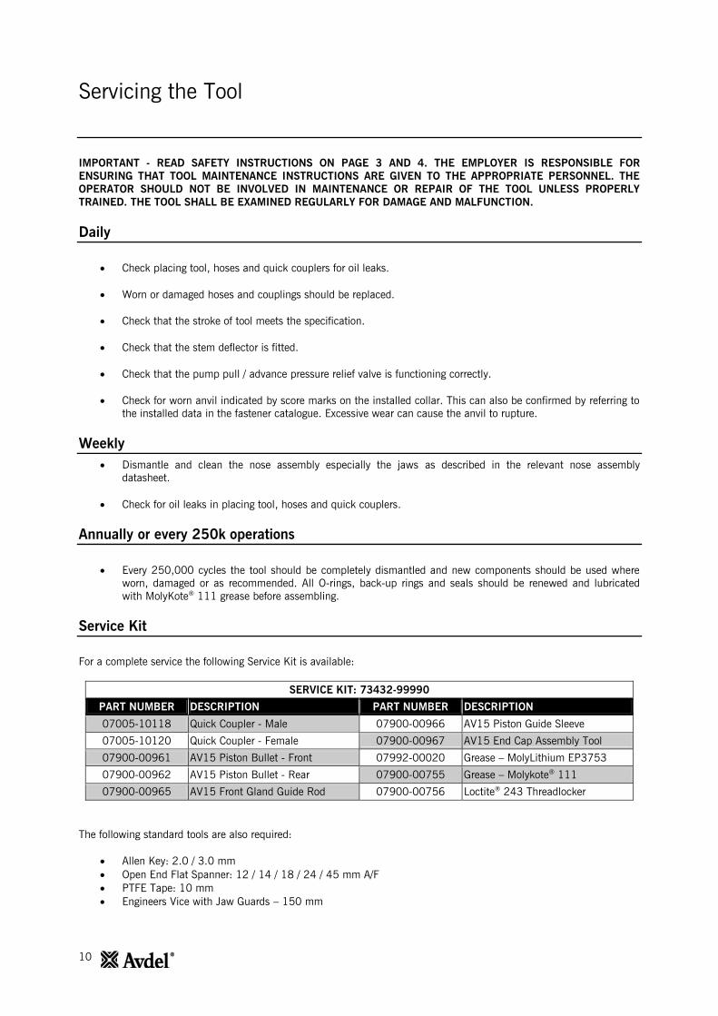
IMPORTANT - READ SAFETY INSTRUCTIONS ON PAGE 3 AND 4. THE EMPLOYER IS RESPONSIBLE FOR
ENSURING THAT TOOL MAINTENANCE INSTRUCTIONS ARE GIVEN TO THE APPROPRIATE PERSONNEL. THE
OPERATOR SHOULD NOT BE INVOLVED IN MAINTENANCE OR REPAIR OF THE TOOL UNLESS PROPERLY
TRAINED. THE TOOL SHALL BE EXAMINED REGULARLY FOR DAMAGE AND MALFUNCTION.
Daily
Check placing tool, hoses and quick couplers for oil leaks.
Worn or damaged hoses and couplings should be replaced.
Check that the stroke of tool meets the specification.
Check that the stem deflector is fitted.
Check that the pump pull / advance pressure relief valve is functioning correctly.
Check for worn anvil indicated by score marks on the installed collar. This can also be confirmed by referring to
the installed data in the fastener catalogue. Excessive wear can cause the anvil to rupture.
Weekly
Dismantle and clean the nose assembly especially the jaws as described in the relevant nose assembly
datasheet.
Check for oil leaks in placing tool, hoses and quick couplers.
Annually or every 250k operations
Every 250,000 cycles the tool should be completely dismantled and new components should be used where
worn, damaged or as recommended. All O-rings, back-up rings and seals should be renewed and lubricated
with MolyKote® 111 grease before assembling.
Service Kit
For a complete service the following Service Kit is available:
SERVICE KIT: 73432-99990
PART NUMBER DESCRIPTION PART NUMBER DESCRIPTION
07005-10118 Quick Coupler - Male 07900-00966 AV15 Piston Guide Sleeve
07005-10120 Quick Coupler - Female 07900-00967 AV15 End Cap Assembly Tool
07900-00961 AV15 Piston Bullet - Front 07992-00020 Grease – MolyLithium EP3753
07900-00962 AV15 Piston Bullet - Rear 07900-00755 Grease – Molykote® 111
07900-00965 AV15 Front Gland Guide Rod 07900-00756 Loctite® 243 Threadlocker
The following standard tools are also required:
Allen Key: 2.0 / 3.0 mm
Open End Flat Spanner: 12 / 14 / 18 / 24 / 45 mm A/F
PTFE Tape: 10 mm
Engineers Vice with Jaw Guards – 150 mm

11
Servicing the Tool
Use only Enerpac® HF hydraulic oil – the use of any other oil may cause the placing tool and pump to malfunction and
will render the placing tool warranty null and void. Hydraulic oil is available to order under the following part numbers.
HYDRAULIC OIL
PART NUMBER 07992-00081 07992-00082 07992-00083
Enerpac® Part Number HF-95X HF-95Y HF-95T
Volume 1 Litre 5 Litres 20 Litres
Viscosity 32 mm2/s 32 mm
2/s 32 mm
2/s
Dismantling Instructions
IMPORTANT – ENSURE THE MAINS POWER SUPPLY TO THE HYDRAULIC PUMP UNIT IS SWITCHED OFF
BEFORE REMOVING THE NOSE ASSEMBLY OR DISMANTLING THE PLACING TOOL.
Before Dismantling:
Uncouple the Quick Couplers 10 and 11 and the electrical Control Cable 14 between the placing tool and the
Hydraulic Hose Assembly.
Remove the nose assembly from the placing tool as per the instructions in the nose assembly datasheet.
For a complete service of the tool, we advise that you proceed with dismantling the tool in the order shown on pages 11
to 14. After dismantling the tool we recommend that you replace all seals.
All numbers in bold refer to the General Assembly and Parts List on pages 15, 16 and 17.
Head Piston Assembly:
Using a small flat screwdriver, remove the Pin 41 from the Collet Adapter 40.
Unscrew and remove the Collet Adapter 40 from the Piston 1.
Remove the Deflector 3, from the End Cap 17.
Clamp the tool handle in a vice with soft jaws so that the tool is pointing nose down. Insert the dowel pins on
the *End Cap Assembly Tool into the three holes in the End Cap 17.
Using a 24 mm A/F spanner, unscrew and remove the End Cap 17, from the Body 2.
Using a small flat screwdriver, remove O-Ring 21 from the End Cap 17 and discard.
Connect the spare *Quick Coupler - Male to the Quick Coupler – Female 11 on the Hydraulic Hose - Return 18.
This will release pressure from the return side of the Piston and ease the removal of the Rear Seal Gland 16.
Insert three M4 screws into the Rear Seal Gland 16, and use them to pull the part off the rear shaft of the
Piston 1 and out of the Body 2.
Using a small flat screwdriver or similar tool, remove O-Ring 30 and Spiral Back-up Ring 36, from the external
groove on the Rear Seal Gland 16, and discard. When removing the seals, take care not to damage the surface
of the Rear Seal Gland with the screwdriver.
Remove Rod Seal 28 and Wiper Seal 31, from the internal grooves on the Rear Seal Gland 16, and discard.
When removing the seals, take care not to damage the surface of the Rear Seal Gland with the screwdriver.
All numbers in bold refer to the General Assembly and Parts List on pages 15, 16 and 17.
* Service Kit on page 10

12
Servicing the Tool
Remove Rear Bearing Ring 29 and check the part for wear or damage. Discard if necessary.
Remove the placing tool from the vice and empty the hydraulic oil from the rear of the tool. Remove the spare
*Quick Coupler – Male from the Quick Coupler - Female 11.
Connect the spare *Quick Coupler - Female to the Quick Coupler - Male 10 on the Hydraulic Hose – Pull 19.
This will release any pressure from the pull side of the Piston 1 and ease the removal of the Piston.
Screw the *Piston Bullet - Front on to the front of the Piston 1.
Place the Body 2 nose up on a bench. Then using a soft mallet, tap the Piston 1 towards the rear of the Body
and out the back end, taking care not to damage the bore within the Body.
Note that when removing the Piston 1, oil on the pull side of the Piston will leak from the front and rear of the
Body 2.
When removing the Piston 1, the Front Seal Gland 15 may be retained on the Piston shaft. If this is the case,
unscrew the *Piston Bullet - Front and pull the Front Seal Gland off of the Piston.
Using a small flat screwdriver remove Piston Seal 26 and the two Anti-Extrusion Rings 27, from the external
groove on the Piston 1, and discard. When removing the seals, take care not to damage the surface of the
Piston with the screwdriver.
If the Front Seal Gland 15 is still retained in the Body 2. Place the Body nose up on a bench and then push the
Front Seal Gland from the front until it is free from the recess within Body. The Front Seal Gland can then be
removed from the back end of the Body. Take care not to damage the bore within the Body when doing so.
Using a small flat screwdriver remove O-Ring 23 and Spiral Back-up Ring 34, from the external groove on the
Front Seal Gland 15, and discard. When removing the seals, take care not to damage the surface of the Front
Seal Gland with the screwdriver.
Remove Rod Seal 25 and Wiper Seal 22, from the internal grooves on the Front Seal Gland 15, and discard.
When removing the seals, take care not to damage the surface of the Front Seal Gland with the screwdriver.
Remove the Front Bearing Ring 24 and check the part for wear or damage. Discard if necessary.
Using a small flat screwdriver, remove O-Ring 21 from the Body 2 and discard.
Remove the spare *Quick Coupler - Female from the Quick Coupler – Male 10 on the Hydraulic Hose – Pull 19.
Do not remove Set Screw 42 from the Body 2.
Assemble in reverse order to dismantling noting the following points:
Clean all components before assembling.
To aid assembly of seals apply a light coating of Molykote® 111 grease to all seals, seal grooves, back-up rings
and the assembly tools.
Slide O-Ring 23 over the Front Seal Gland 15 and into the external groove. Insert the Spiral Back-up Ring 34 in
the same groove, in front of the installed O-Ring. Refer to the General Assembly and Parts List for the correct
orientation of the O-Ring and Spiral Back-up Ring.
All numbers in bold refer to the General Assembly and Parts List on pages 15, 16 and 17.
* Service Kit on page 10
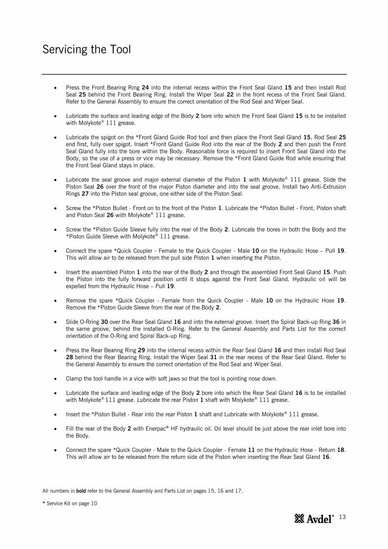
13
Servicing the Tool
Press the Front Bearing Ring 24 into the internal recess within the Front Seal Gland 15 and then install Rod
Seal 25 behind the Front Bearing Ring. Install the Wiper Seal 22 in the front recess of the Front Seal Gland.
Refer to the General Assembly to ensure the correct orientation of the Rod Seal and Wiper Seal.
Lubricate the surface and leading edge of the Body 2 bore into which the Front Seal Gland 15 is to be installed
with Molykote® 111 grease.
Lubricate the spigot on the *Front Gland Guide Rod tool and then place the Front Seal Gland 15, Rod Seal 25
end first, fully over spigot. Insert *Front Gland Guide Rod into the rear of the Body 2 and then push the Front
Seal Gland fully into the bore within the Body. Reasonable force is required to insert Front Seal Gland into the
Body, so the use of a press or vice may be necessary. Remove the *Front Gland Guide Rod while ensuring that
the Front Seal Gland stays in place.
Lubricate the seal groove and major external diameter of the Piston 1 with Molykote® 111 grease. Slide the
Piston Seal 26 over the front of the major Piston diameter and into the seal groove. Install two Anti-Extrusion
Rings 27 into the Piston seal groove, one either side of the Piston Seal.
Screw the *Piston Bullet - Front on to the front of the Piston 1. Lubricate the *Piston Bullet - Front, Piston shaft
and Piston Seal 26 with Molykote® 111 grease.
Screw the *Piston Guide Sleeve fully into the rear of the Body 2. Lubricate the bores in both the Body and the
*Piston Guide Sleeve with Molykote® 111 grease.
Connect the spare *Quick Coupler - Female to the Quick Coupler - Male 10 on the Hydraulic Hose – Pull 19.
This will allow air to be released from the pull side Piston 1 when inserting the Piston.
Insert the assembled Piston 1 into the rear of the Body 2 and through the assembled Front Seal Gland 15. Push
the Piston into the fully forward position until it stops against the Front Seal Gland. Hydraulic oil will be
expelled from the Hydraulic Hose – Pull 19.
Remove the spare *Quick Coupler - Female from the Quick Coupler - Male 10 on the Hydraulic Hose 19.
Remove the *Piston Guide Sleeve from the rear of the Body 2.
Slide O-Rring 30 over the Rear Seal Gland 16 and into the external groove. Insert the Spiral Back-up Ring 36 in
the same groove, behind the installed O-Ring. Refer to the General Assembly and Parts List for the correct
orientation of the O-Ring and Spiral Back-up Ring.
Press the Rear Bearing Ring 29 into the internal recess within the Rear Seal Gland 16 and then install Rod Seal
28 behind the Rear Bearing Ring. Install the Wiper Seal 31 in the rear recess of the Rear Seal Gland. Refer to
the General Assembly to ensure the correct orientation of the Rod Seal and Wiper Seal.
Clamp the tool handle in a vice with soft jaws so that the tool is pointing nose down.
Lubricate the surface and leading edge of the Body 2 bore into which the Rear Seal Gland 16 is to be installed
with Molykote®
111 grease. Lubricate the rear Piston 1 shaft with Molykote® 111 grease.
Insert the *Piston Bullet - Rear into the rear Piston 1 shaft and Lubricate with Molykote® 111 grease.
Fill the rear of the Body 2 with Enerpac® HF hydraulic oil. Oil level should be just above the rear inlet bore into
the Body.
Connect the spare *Quick Coupler - Male to the Quick Coupler - Female 11 on the Hydraulic Hose - Return 18.
This will allow air to be released from the return side of the Piston when inserting the Rear Seal Gland 16.
All numbers in bold refer to the General Assembly and Parts List on pages 15, 16 and 17.
* Service Kit on page 10

14
Servicing the Tool
Place the Rear Seal Gland 16 over the *Piston Bullet - Rear. Then push the Rear Seal Gland over the Piston 1
shaft and into the rear of the Body 2. Push the Rear Seal Gland into the Body until a few internal threads are
exposed at the rear of the Body. Take care not to damage the O-Ring 30 and Spiral Back-up Ring 36 on the
threads when inserting the Rear Seal Gland.
Lubricate both the internal thread in the Body 2 and the external thread on End Cap 17 with MolyLithium
Grease.
Screw the End Cap 17 fully into the rear of the Body 2 using the *End Cap Assembly Tool. In doing so, the
Rear Seal Gland 16 will be pressed into position within the Body and a small amount of oil will be expelled
from the Hydraulic Hose - Return 18.
Remove spare *Quick Coupler - Male from the Quick Coupler - Female 11 on the Hydraulic Hose – Return 18.
Push the Deflector 3, on the End Cap 17.
Screw the Collet Adapter 40 on to the Piston 1 until the front face is flush with the end of the Piston. Align the
hole in the Collet Adapter with the slot in the end of the Piston and then insert Locking Pin 41.
Prime the placing tool as described in Preparation for Use on page 8.
Hose Assembly:
Remove the two Screws 9 from the Hose Clamp 13 using a 3.0mm Allen Key. Remove the Hose Clamp and
Clamp Insert 20 from the Protective Sleeve 37 and Hydraulic Hoses 18 and 19.
Using the small flat screwdriver prize the Handle Gator 8 from the handle of Body 2. Pull the Handle Gator over
the Protective Sleeve 37, Hydraulic Hoses 18 and 19 and remove.
Cut the Cable Tie 35 and slide back the Protective Sleeve 37 to expose the fittings on the Hydraulic Hoses 18
and 19. The Hydraulic Hoses can be removed form the Body 2 using 12mm and 14mm spanners.
The Quick Couplers 10 and 11 can be removed from the Hydraulic Hoses 18 and 19 using 18mm and 24mm
spanners.
To remove Trigger Switch 7, first loosen Cable Gland 38, so that the Control Cable 14 is free to move within the
Body 2. Then undo M4 Set Screw 12 using a 2.0mm Allen Key.
Push the Control Cable 14 into the Body 2 and simultaneously pull the Trigger Switch 7 out of the Body to
expose the solder joints on the Trigger Switch terminals. Unsolder the terminals to remove the Trigger Switch
and Trigger Insert 39. The Trigger Insert is bonded to the Trigger Switch and cannot be removed.
The Control Cable 14 can now be pulled from the Body 2 and removed from the Protective Sleeve 37.
Assemble in reverse order to dismantling noting the following points:
Prior to assembly clean all threads on the Quick Couplers - Male 10 and Female 11 and the Hydraulic Hoses –
Return 18 and Pull 19. Apply 2 to 3 layers of 10mm PTFE tape to the male threads of both Hydraulic Hoses.
When replacing the Trigger Switch 7 apply Loctite® 243 to the male thread on the Trigger Switch before
assembling the Trigger Insert 39.
Apply Loctite® 243 to M4 Set Screw 12 prior to assembly.
Once assembled, prime the tool as per the instructions on page 8.
All numbers in bold refer to the General Assembly and Parts List on pages 15, 16 and 17.
* Service Kit on page 10
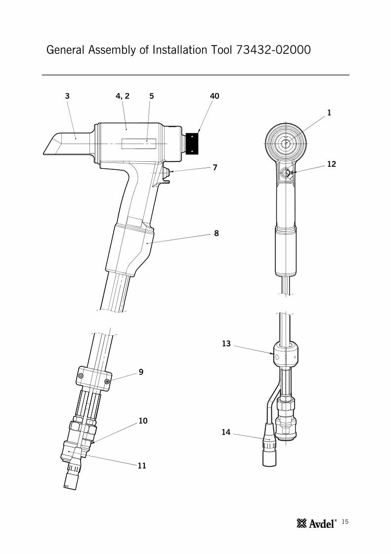
15
General Assembly of Installation Tool 73432-02000
3 4, 2 5 40
7
8
12
1
9
10
11
13
14

16
General Assembly of Installation Tool 73432-02000
21 22 34 23 24 25 26 27
39
28 29 30 36 31 21
35
37
38
DETAIL B
DETAIL C
DETAIL D
DETAIL E
42
DETAIL F
41 15 1 17
E
D
18
19
16
B
C
F
20

17
Parts List for Installation Tool 73432-02000
73432-02000 Parts List
ITEM PART NUMBER DESCRIPTION QTY.
1 73432-02003 PISTON 1
2 73432-02001 BODY 1
3 73432-02011 DEFLECTOR 1
4 73430-02025 SAFETY LABEL 1
5 73432-02026 AV15 LABEL 2
6
7 07007-02103 TRIGGER SWITCH 1
8 73430-02020 HANDLE GATOR 1
9 07001-00686 M4 X 16 SKT CAP HD SCREW 2
10 07005-10118 QUICK COUPLER - MALE 1
11 07005-10120 QUICK COUPLER - FEMALE 1
12 07001-00479 M4 X 4 SKT SET SCREW 1
13 73430-02023 HOSE CLAMP 1
14 07007-02105 CONTROL CABLE 1
15 73432-02004 FRONT SEAL GLAND 1
16 73432-02006 REAR SEAL GLAND 1
17 73432-02005 END CAP 1
18 07005-10119 HYDRAULIC HOSE - RETURN 1
19 07005-10117 HYDRAULIC HOSE - PULL 1
20 73430-02024 CLAMP INSERT 1
21 07003-00460 O-RING 2
22 07003-00446 WIPER SEAL 1
23 07003-00459 O-RING 1
24 73432-02009 FRONT BEARING RING 1
25 07003-00445 ROD SEAL 1
26 07003-00449 PISTON SEAL 1
27 07003-00450 ANTI-EXTRUSION RING 2
28 07003-00447 ROD SEAL 1
29 73432-02010 REAR BEARING RING 1
30 07003-00462 O-RING 1
31 07003-00448 WIPER SEAL 1
32
33
34 07003-00493 SPIRAL BACK-UP RING 1
35 07007-02032 CABLE TIE 1
36 07003-00495 SPIRAL BACK-UP RING 1
37 07005-10121 PROTECTIVE SLEEVE 0.6m
38 07007-02104 CABLE GLAND 1
39 73430-02008 TRIGGER INSERT 1
40 73432-02012 COLLET ADAPTER - AV15 1
41 73432-02013 LOCKING PIN - AV15 1
42 07001-00481 M5 X 5 SKT SET SCREW 1
- 07900-01021 AV15 TOOL INSTRUCTION MANUAL 1
18
Safety Data
Enerpac®
HF Hydraulic Oil - Safety Data
FIRST AID
SKIN:
Unlikely to cause harm to the skin on brief or occasional contact but prolonged or exposure may lead to dermatitis. Wash
skin thoroughly with soap and water as soon as reasonably practicable. Remove heavily contaminated clothing and wash
underlying skin.
ORAL:
Unlikely to cause harm if accidentally swallowed in small doses, though larger quantities may cause nausea and
diarrhea. If contamination of the mouth occurs, wash out thoroughly with water. Except as a deliberate act, the ingestion
of large amounts of product is unlikely. If it should occur, do not induce vomiting; obtain medical advice. Take person to
nearest medical centre.
EYES:
Unlikely to cause more than transient stinging or redness if accidental eye contact occurs. Wash eyes thoroughly with
copious quantities of water, ensuring eyelids are held open. Obtain medical advice if any pain or redness develops or
persists.
MEDICAL ADVICE:
Treatment should in general be symptomatic and directed to relieving any effects.
Note: High Pressure Applications:
Injections through the skin, resulting from contact with the product at high pressure, constitute a major medical
emergency. Injuries may not appear serious at first but within a few hours tissue becomes swollen, discoloured and
extremely painful with extensive subcutaneous necrosis.
Surgical exploration should be undertaken without delay. Thorough and extensive debridement of the wound and
underlying tissue is necessary to minimize tissue loss and prevent or limit permanent damage. Note that high pressure
may force the product considerable distances along tissue planes.
DISPOSAL
Remove all spills with inert absorbent material. Ventilate spill area. Place contaminated materials in a disposable
container and dispose in a manner consistent with local regulations.
FIRE
FLASH POINT: 200°C.
Extinguish with either dry chemical, foam or carbon dioxide. Do not enter confined space without self contained breathing
apparatus.
HANDLING
Use barrier cream or oil resistant gloves.
STORAGE
Undercover and consistent with local regulations for inflammable material.
MolyLithium Grease EP 3753 - Safety Data
Grease can be ordered as a single item, the part number is shown in the Service Kit page 10.
FIRST AID
SKIN:
As the grease is completely water resistant it is best removed with an approved emulsifying skin cleaner.
INGESTION:
Ensure the individual drinks 30ml Milk of Magnesia, preferably in a cup of milk.
EYES:
Irritant but not harmful. Irrigate with water and seek medical attention.

19
Safety Data
FIRE
FLASH POINT: Above 220°C.
Not classified as flammable.
Suitable extinguishing media: CO2, Halon or water spray if applied by an experienced operator.
ENVIRONMENT
Scrape up for incineration or disposal on approved site.
HANDLING
Use barrier cream or oil resistant gloves
STORAGE
Away from heat and oxidising agent.
Molykote®
111 Grease - Safety Data
Grease can be ordered as a single item, the part number is shown in the Service Kit page 10.
FIRST AID
SKIN:
No first aid should be needed.
INGESTION:
No first aid should be needed.
EYES:
No first aid should be needed.
INHALATION:
No first aid should be needed.
FIRE
FLASH POINT: Above 101.1°C. (closed cup)
Explosive Properties: No
Suitable Extinguishing Media: Carbon Dioxide Foam, Dry Powder or fine water spray. Water can be used to cool fire
exposed containers.
ENVIRONMENT
No adverse effects are predicted.
HANDLING
General ventilation is recommended. Avoid eye contact.
STORAGE
Do not store with oxidizing agents. Keep container closed and store away from water or moisture.

20
Fault Diagnosis
SYMPTOM POSSIBLE CAUSE REMEDY PAGE REF.
Placing Tool will not
operate
Inoperative pump unit
Check pump power supply and
refer to pump unit instruction
manual
Faulty Quick Couplers 10 and 11 Replace Quick Couplers 14
Trigger Control Cable 14 not
connected correctly
Check Control Cable is correctly
connected at pump and placing
tool
8
Damaged Trigger Switch 7 or
Control Cable 14
Replace Trigger Switch and/or
Control Cable 14
Trigger Switch 7 does
not function
Pump in local mode Refer to pump instruction manual
Trigger Switch 7, Control Cable
14 or connector damaged
Replace Trigger Switch and/or
Control Cable 14
Pump running but
placing tools does not
function
Hydraulic Hoses not connected Check for correct connections at
pump and placing tool 8
Low oil level
Ensure placing tool is filled with
oil and correctly primed
Refer to pump instruction manual
8
Placing tool external oil leak Inspect placing tool – replace
worn or damaged components 11 - 14
Hose Assembly external oil leak
Inspect Hose Assembly – ensure
hose connections are tight and/or
replace damaged hose
connectors
14
Pump internal/external oil leak Refer to pump instruction manual
Placing tool operates
erratically
Low or erratic hydraulic pressure
supply Refer to pump instruction manual
Worn or damaged hydraulic seals
in placing tool
Inspect placing tool – replace
worn or damaged seals 11 - 14
Worn or damaged hydraulic
sealing surfaces in placing tool
Inspect placing tool – replace
worn or damaged components 11 - 14
Pump internal/external oil leak Refer to pump instruction manual
Pump builds full
pressure, but pintail
does not break
Breakload greater than placing
tool capacity at full pressure Refer to placing tool specification 5
Flow to placing tool blocked Check Quick Couplers 10 and 11
for full engagement 8
Pump pressure relief value set
too low
Adjust pressure relief valve
settings – refer to pump
instruction manual
Pull grooves on fastener pintail
stripped See Symptom on page 21 9
Improper tool operation 9

21
Fault Diagnosis
SYMPTOM POSSIBLE CAUSE REMEDY PAGE REF.
Placing tool Piston 1
will not return
Return flow restricted or blocked Check Quick Couplers 10 and 11
for full engagement and/or fault 8
Hydraulic Hoses not connected Check for correct connections at
pump and placing tool 8
Pump valve malfunction Refer to pump instruction manual
Placing tool does not
eject the collar from
the anvil
Pump Return Timer setting
incorrect – set too low
Adjust Return Timer to
recommended setting – refer to
pump instruction manual
Pump return pressure relief valve
set too low
Adjust return pressure relief valve
to correct setting – refer to pump
instruction manual
Low or erratic hydraulic pressure
supply Refer to pump instruction manual
Worn or damaged hydraulic seals
in placing tool
Inspect placing tool – replace
worn or damaged seals 11 - 14
Worn or damaged hydraulic
sealing surfaces in placing tool
Inspect placing tool – replace
worn or damaged components 11 - 14
Pump internal/external oil leak Refer to pump instruction manual
Pull grooves on
fastener pintail
stripped during
installation
Operator not pushing nose
completely onto fastener pintail
before operating tool
Instruct operator in correct
installation method 9
Incorrect fastener length / grip
length
Worn or damaged jaw segments
Use correct fastener
Check and replace jaw set – refer
to nose equipment datasheet
9
Debris in jaw segments and/or
pintail grooves
Clean jaw segments – refer to
nose equipment datasheet
Excessive sheet gap Close gap between sheets 9
Avbolt® or Infalok
®
collar not fully swaged
Improper tool operation 9
Worn Anvil bore Check and replace Anvil – refer to
nose equipment datasheet
Pintail fails to release
from nose equipment
Incorrect assembly of nose
equipment
Refer to nose equipment
datasheet
Placing tool and
Hydraulic oil runs hot
Restriction in hydraulic line
Check hydraulic Quick Couplers
10 and 11 and replace if
necessary
14
High ambient temperature
Hydraulic Quick
Couplers 10 and 11
leak oil
Worn O-Ring in body of Quick
Coupler Male 10
Replace O-Ring and Back-up
Ring in Quick Coupler 10 14

22
Notes

23
Declaration of Conformity
We, Avdel UK Limited, Watchmead Industrial Estate, Welwyn Garden City, Herts, AL7 1LY declare under our sole
responsibility that the product:
Model: AV™15 INSTALLATION TOOL – 73432-02000
Serial No: ....
To which this declaration relates is in conformity with the following standards:
EN ISO 12100 - parts 1 & 2
BS EN ISO 8662 - part 6 BS EN ISO 11202
BS EN ISO 3744 BS EN 982
ISO EN 792 part 13 - 2000 BS EN 983
Following the provisions of the Machine Directive 2006/42/EC
A K Seewraj – Technology Manager
Welwyn Garden City - date of issue
A
This box contains a power tool which is in conformity with Machines Directive
2006/42/EC. The ‘Declaration of Conformity’ is contained within.

24
AUSTRALIA
Infastech (Australia) Pty Ltd.
891 Wellington Road
Rowville
Victoria 3178
Tel: +61 3 9765 6400
Fax: +61 3 9765 6445
CANADA
Avdel Canada Limited
1030 Lorimar Drive
Mississauga
Ontario L5S 1R8
Tel: +1 905 364 0664
+800 268 9947
Fax: +1 905 364 0678
+800 594 7661
CHINA
Infastech (China) Ltd.
RM 1708, 17/F.,
Nanyang Plaza,
57 Hung To Rd., Kwun Tong
Hong Kong
Tel: +852 2950 0631
Fax: +852 2950 0022
FRANCE
Avdel France S.A.S.
Bat. Le Monet Paris Nord 2
9 Allée des Impressionistes
CS 59328 Villepinte
95941 Roissy CDG Cedex
Tel: +33 (0) 149 909500
Fax: +33 (0) 149 909550
GERMANY
Avdel Deutschland GmbH
Rotenburger Str. 28
30659 Hannover
Tel: +49 (0)511 7288 0
Fax: +49 (0)511 7288 133
m
INDIA
Infastech Fastening Technologies
India Private Limited
Plot No OZ-14, Hi Tech SEZ,
SIPCOT Industrial Growth Center,
Oragadam, Sriperumbudur Taluk,
Kanchipuram District,
602105 Tamilnadu
Tel: +91 44 4711 8001
Fax: +91 44 4711 8009
ITALY
Avdel Italia S.r.l.
Viale Lombardia 51/53
20861 Brugherio (MB)
Tel: +39 039 289911
Fax: +39 039 2873079
JAPAN
Infastech Kabushiki Kaisha
Center Minami SKY,
3-1 Chigasaki-Chuo, Tsuzuki-ku,
Yokohama-city,
Kanagawa Prefecture
Japan 224-0032
Tel: +81 45 947 1200
Fax: +81 45 947 1205
MALAYSIA
Infastech (Malaysia) Sdn Bhd
Lot 63, Persiaran Bunga
Tanjung 1,
Senawang Industrial Park
70400 Seremban
Negeri Sembilan
Tel: +606 676 7168
Fax: +606 676 7101
SINGAPORE
Infastech (Singapore) Pte Ltd.
31 Kaki Bukit Road 3
#05-03/06 Techlink
Singapore, 417818
Tel: +65 6372 5653
Fax: +65 6744 5643
SOUTH KOREA
Infastech (Korea) Ltd.
32-9, Jik-dong,
Gwangju-si, Gyeonggi-do,
Korea, 464-090
Tel: +82 1661 6342
+82 31 798 6340
Fax: +82 31 798 6342
SPAIN
Avdel Spain S.A.
C/ Puerto de la
Morcuera, 14
Poligono Industrial Prado
Overa
Ctra. de Toledo, km 7,8
28919 Leganés (Madrid)
Tel: +34 91 3416767
Fax: +34 91 3416740
TAIWAN
Infastech/Tri-Star Limited
No 269-7, Baodong Rd,
Guanmiao Dist.
Tainan City
Taiwan, R.O.C. 71841
Tel: +886 6 596 5798 (ext 201)
Fax: +886 6 596 5758
THAILAND
Infastech Thai Co., Ltd
64/132 Moo 4 Tambon
Pluakdaeng
Amphur Pluakdaeng Rayong
21140 Thailand
Tel: +66 (0) 38 656360
Fax: +66 (0) 38 656346
UNITED KINGDOM
Avdel UK Limited
Pacific House
2 Swiftfields
Watchmead Industrial Estate
Welwyn Garden City
Hertfordshire AL7 1LY
Tel: +44 (0) 1707 292000
Fax: +44 (0) 1707 292199
USA
Avdel USA LLC
614 NC Highway 200 South
Stanfield, North Carolina 28163
Tel: +1 704 888 7100
Fax: +1 704 888 0258
Infastech (Decorah) LLC
1304 Kerr Drive
Decorah, IA 52101
Tel: +1 563 382 4216
Fax: +1 563 387 3540
Manual No. Issue Change Note No. www.avdel-global.com
07900-01021 B 12/153 www.infastech.com
AV™, Autosert® (equipment), Avbolt®, Avdel®, Avdelmate®, Avdel TX2000®, Avdelok®, Avex®, Avibulb®, Avinox®, Avinut®, Avlug®, Avmatic®,
Avplas®, Avseal®, Avsert®, Avtainer®, Avtronic®, Briv®, Bulbex®, Chobert®, Eurosert®, Fastriv®, Finsert®, Genesis®, Grovit®, Hemlok®, Hexsert®,
Holding your world together®, Hydra®, Infalok®, Interlock®, Klamp-Tite®, Klamptite KTR®, Kvex®, Maxlok®, Monobolt®, Monobulb®, Neobolt®,
Nutsert®, Nutsert SQ®, Portariv®, Rivmatic®, Rivscrew®, Speed Fastening®, Squaresert®, Stavex®, Supersert®, Thin Sheet Nutsert®, Titan®, T-
Lok®, TLR®, TSN®, TX2000®, Versa-Nut®, Viking® and Viking 360® are trademarks of Avdel UK Limited. eRiv™, Infastech®, NeoSpeed® and
Our Technology, Your Success™ are trademarks of Infastech Intellectual Properties Pte Ltd. The names and logos of other companies
mentioned herein may be trademarks of their respective owners.
This document is for informational purposes only. Infastech makes no warranties, expressed or implied, in this document.
Data shown is subject to change without prior notice as a result of continuous product development and improvement policy.
Your local Avdel representative is at your disposal should you need to confirm latest information.
© 0
4.2
01
2 I
nfa
ste
ch