SISTEMA CONTROL MIX · 2016-10-05 · C. Las normas peruanas NTP están basadas en las normas ASTM...
81
Jr. Bajada Balta 169, Oficina 702 – Miraflores - Lima 18 Teléfonos: 2430414, Celular : 998133533, e-mail : [email protected] Rev.08 1 SISTEMA CONTROL MIX EXPEDIENTE TÉCNICO 2016
Transcript of SISTEMA CONTROL MIX · 2016-10-05 · C. Las normas peruanas NTP están basadas en las normas ASTM...

Jr. Bajada Balta 169, Oficina 702 – Miraflores - Lima 18 Teléfonos: 2430414, Celular : 998133533, e-mail : [email protected] Rev.08
1
SISTEMA CONTROL MIX
EXPEDIENTE TÉCNICO
2016

Jr. Bajada Balta 169, Oficina 702 – Miraflores - Lima 18 Teléfonos: 2430414, Celular : 998133533, e-mail : [email protected] Rev.08
2
SISTEMA CONTROL MIX EXPRESSEXPEDIENTE TÉCNICO
1. DESCRIPCIÓN GENERAL
A. El Sistema Control Mix está constituido por un círculo de calidad de 6 etapas para garantizar: 1) el muestreo, 2) moldeo, 3) transporte a laboratorio, 4) curado, 5) ensayo en compresión y 6) remisión de resultados de ensayos en cumplimiento de las normas estándar aplicables.
B. Las normas estándar en su última versión bajo las cuales se ha configurado el Sistema Control Mix son :
ASTM C31/C31M-15-ae1 "Standard Practice for Making and Curing Concrete TestSpecimens in the Field".
ASTM C39/C39M-16b "Standard Test Method for Compressive Strength of CylindricalConcrete Specimens".
ASTM C172/C172M-14a"Standard Practice for Sampling Freshly Mixed Concrete".
ASTM C470/C470M-15 "Standard Specification for Molds for Forming Concrete TestCylinders Vertically".
ASTM C511-13 "Standard Specification for Mixing Rooms, Moist Cabinets, Moist Rooms,and Water Storage Tanks Used in the Testing of Hydraulic Cements and Concretes".
ASTM C1231/1231M-15 "Standard Practice for Use of Unbonded Caps in Determinationof Compressive Strength of Hardened Concrete Cylinders"
ASTM C1077-16 “Standard Practice for Agencies Testing Concrete and ConcreteAggregates for Use in Construction and Criteria for Testing Agency Evaluation”
C. Las normas peruanas NTP están basadas en las normas ASTM detalladas, sin embargo, se ha decidido emplear la fuente original dado que corresponden a las versiones revisadas y actualizadas regularmente, y nuestra Norma E 060-2009 define su empleo en vez de las Normas NTP para el caso particular del muestreo y ensayo de concreto. (Acápites 5.6.3.1 y 5.6.3.2)
2. DETALLES TÉCNICOS DEL SISTEMA CONTROL MIX
2.1 ETAPA 1 : MUESTREO DEL CONCRETO FRESCO EN OBRA
A. El muestreo del concreto en obra en conformidad con el Sistema Control Mix es ejecutado por personal designado por el cliente, previa capacitación, evaluación y certificación a cargo de especialistas de Control Mix Express (CME).
B. En el Anexo I se adjuntan los documentos que habilitan al suscrito, la Ing. Mercedes Neyra y la Ing. Mariella Durand como instructores certificados para la capacitación en las Normas ASTM incluidas en el Código ACI-318 y los Técnicos Richard Lino, Fortunato Villanueva, Edgard Saavedra, responsables de las capacitaciones prácticas del personal en obra.
C. La capacitación que imparte CME está basada en el Programa de Certificación para Técnicos de Control de Concreto Grado I del American Concrete Institute - ACI, en los aspectos de muestreo, moldeo de testigos en campo, determinación del

Jr. Bajada Balta 169, Oficina 702 – Miraflores - Lima 18 Teléfonos: 2430414, Celular : 998133533, e-mail : [email protected] Rev.08
3
asentamiento (slump) y medición de temperatura del concreto fresco conforme a las Normas ASTM aplicables.
D. Al personal que aprueba la evaluación teórica y práctica que considera el Programa de Capacitación se le asigna un código de certificación, siendo el único personal reconocido por el Sistema Control Mix como habilitado para el muestreo y moldeo de los testigos en obra, no recibiéndose ningún testigo que no haya sido muestreado y moldeado por dicho personal calificado, en cumplimiento de las Normas ASTM C31. En el Anexo I se adjunta un ejemplo de Certificado.
E. El personal que haya aprobado la capacitación práctica pero tenga pendiente la Capacitación teórica, será separado por el personal de CME mientras no cumpla con este requisito.
2.2 ETAPA 2 : MOLDEO DE TESTIGOS DE CONCRETO
A. Luego de ser efectuado el muestreo del concreto fresco, por parte del personal certificado del cliente, en la oportunidad y frecuencia que éste considere conveniente según la norma ASTM C 31, este personal procede al moldeo de los testigos cilíndricos.
B. El Sistema Control Mix considera el suministro y empleo de módulos para testigos constituidos por una caja de madera para protección y traslado de testigos de diseño original de CME, 6 moldes cilíndricos plásticos de 4" de diámetro x 8"de altura, varilla compactadora, martillo de goma y regla enrasadora previstos por la norma ASTM C31.
C. Los moldes plásticos han sido fabricados para CME cumpliendo los requisitos y tolerancias de la Norma ASTM C470 y constan adicionalmente de una tapa también de plástico de ajuste hermético, para garantizar el mantenimiento de la humedad del testigo luego de moldeado y enrasado.
D. Efectuado el moldeo de los testigos en condición estándar controlada, el personal certificado coloca cuidadosamente los moldes con tapa dentro de la caja de madera, que tiene la doble función de proteger los testigos de golpes o maltratos durante las 48 horas previas a su traslado al laboratorio y proveer aislamiento térmico para asegurar que los testigos se mantengan dentro del rango de temperatura de 16ºC a 27ºC, o curado inicial a ser garantizado en el periodo indicado, en cumplimiento de ASTM C31 para que no se afecte la resistencia a 28 días.
E. El personal responsable del moldeo de los testigos tiene a su cargo la generación de la orden de servicio para CME con todos los detalles relativos al tipo de concreto, procedencia, fechas de ensayo, etc. que deberán figurar en el certificado de ensayos correspondiente y que adjuntará a cada módulo de testigos, incluyéndose en el Anexo II el formato correspondiente.
2.3 ETAPA 3 : TRANSPORTE DE MÓDULOS CON TESTIGOS AL LABORATORIO
A. El transporte al laboratorio es efectuado por personal técnico de CME en unidades móviles con anaqueles especialmente acondicionados para el traslado de los módulos de madera con los testigos, a fin de garantizar que no sufran golpes ni daños.

Jr. Bajada Balta 169, Oficina 702 – Miraflores - Lima 18 Teléfonos: 2430414, Celular : 998133533, e-mail : [email protected] Rev.08
4
B. En conformidad con ASTM C31, el transporte se efectúa no antes de 8 horas de producido el fraguado final del concreto, ni después de 48 horas de haberse moldeado los testigos, no debiendo durar el traslado más de 4 horas.
2.4 ETAPA 4 : CURADO EN CONDICIONES CONTROLADAS
A. Los testigos son trasladados al Laboratorio de CME en Villa El Salvador donde se ingresa y registra cada módulo con su orden de servicio correspondiente en la base de datos del software original patentado que forma parte del Sistema Control Mix.
B. El software registra también la ubicación matricial única que tendrán los testigos en los anaqueles de las cámaras de curado, emitiendo etiquetas con códigos de barras para su identificación.
C. Los testigos se desmoldan y de inmediato se le colocan sus etiquetas de identificación, colocándose en grupos de 3 en cajas plásticas de diseño especial numeradas, para su almacenaje ordenado en los anaqueles de los cuartos de curado.
D. Se cuenta con cajas numeradas de color rojo donde se depositan los testigos a ensayarse a edad temprana (normalmente a 7 días o la edad que requiera el cliente ) y también con cajas de color azul para almacenar los testigos a probarse a 28 días o mayor edad si lo requiere el cliente, de tal forma de eliminar cualquier posibilidad de confusión en almacenaje e identificación de los testigos.
E. En un periodo máximo de 30 minutos luego de ser desmoldados, etiquetados y colocados en sus cajas plásticas, los testigos se trasladan a su ubicación programada en las cámaras de curado.
F. Las cámaras de curado cumplen con los requisitos de la Norma ASTM C511 y cuentan con un sistema de circuito cerrado de aspersores aéreos de neblina y un tanque de agua con bomba recirculante y control de temperatura para garantizar el mantenimiento de la humedad superficial permanente y la temperatura en el rango de 21ºC a 25ºC previsto en ASTM C31.
2.5 ETAPA 5 : ENSAYO EN COMPRESIÓN DE LOS TESTIGOS
A. El software del Sistema Control Mix emite diariamente un reporte de los testigos programados para ser ensayados en la fecha, con su ubicación matricial en las cámaras de curado, a fin de que sean trasladados al laboratorio de ensayos.
B. Los testigos se trasladan en sus cajas de curado al laboratorio de ensayos para mantener su condición de humedad hasta el momento de ser probados.
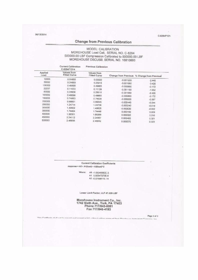
C. Se cuenta con cuatro prensas británicas Marca JV Tech, Nº de Serie 0431138 y Nº Serie 0481313, Serie 0501503, Serie 14001438 digitales, totalmente automatizadas, controladas por el software del Sistema Control Mix y con certificados de calibración vigentes emitidos por la empresa Celda EIRL, empleando celda de calibración trazable al NIST (United States National Institute of Standards & Technology) en conformidad con la Norma ASTM E74-13a, adjuntándose una copia de los certificados en el Anexo III.

Jr. Bajada Balta 169, Oficina 702 – Miraflores - Lima 18 Teléfonos: 2430414, Celular : 998133533, e-mail : [email protected] Rev.08
5
D. Como elemento de distribución de carga en el ensayo de compresión se emplean cabezales de acero y pads de neopreno en conformidad con la Norma ASTM C1231.
E. Luego de colocado el testigo en su posición de ensayo en la prensa, se procede a escanear el código de barras para su reconocimiento por el software, y la comprobación de que procede el ensayo programado, con lo que el técnico autoriza a través de la computadora el inicio de la prueba que se efectúa automáticamente sin intervención de ningún personal, con la velocidad de carga programada previamente dentro del rango de 0.20 Mpa/seg a 0.30 Mpa/seg establecido en ASTM C39.
F. Conseguida la rotura del testigo y registrada la carga máxima el técnico registra el tipo de falla según ASTM C39 y autoriza que el software grabe la información, con lo que se calcula el esfuerzo máximo sobre la base del diámetro del testigo ingresado previamente al sistema y el área correspondiente de la sección.
2.6 ETAPA 6 : EMISIÓN Y ENVÍO DEL CERTIFICADO DE ENSAYOS
A. Cada vez que se completa la rotura de un grupo de 3 testigos de 4" x 8", (cuyo promedio es considerado por ACI 318 como representativo de la resistencia en compresión de la muestra), el software procede a generar y emitir en formato pdf, el certificado o reporte correspondiente acorde con el acápite 9. de ASTM C39, avalado con la firma de Ingeniero Civil Colegiado Especialista, Responsable Técnico, tal como lo consideran los dispositivos legales vigentes.
B. El certificado generado y emitido como se menciona anteriormente es almacenado en una base de datos de uso y acceso exclusivo del cliente, a quién el software le envía de inmediato un correo electrónico a las casillas que haya declarado previamente, con el aviso de la disponibilidad del certificado de ensayos y un enlace para que proceda a descargarlo en formato pdf e imprimirlo a voluntad.
C. En el Anexo IV se incluye un formato de certificado de ensayos.
D. Por razones de seguridad informática y resguardo, toda la información registrada y generada por el software es almacenada simultáneamente en un servidor residente en las Oficinas de CME en Miraflores, un segundo servidor en el Laboratorio en Villa El Salvador y un tercer servidor dedicado alojado en un servicio por internet contratado en Alemania.
E. Se adjunta como documento gráfico en el Anexo V el link de descarga del video ilustrativo de los procesos del Sistema Control Mix, y en el website www.controlmixexpress.com se puede acceder a un demo de los servicios mencionados.
3. SISTEMA DE GESTIÓN ISO 9001:2008
A. El Sistema Control Mix cuenta con certificación ISO 9001:2008 Nº PE14/175309 emitida por SGS United Kingdom Ltd Systems & Services Certification con fecha 04/02/14, que abarca los rubros previamente detallados. (Ver Anexo IX)

Jr. Bajada Balta 169, Oficina 702 – Miraflores - Lima 18 Teléfonos: 2430414, Celular : 998133533, e-mail : [email protected] Rev.08
6
4. SERVICIOS COMPLEMENTARIOS DE CONTROL MIX EXPRESS S.A.C.
A. CME pone a disposición gratuita para uso exclusivo de sus clientes el Módulo Informático Control Data que evalúa según ACI-318 la estadística generada.
B. Como servicios complementarios Control Mix Express SAC realiza extracción, recorte y ensayos de núcleos de concreto con brocas diamantinas de 2", 3" y 4" de diámetro en conformidad con la norma ASTM C 42
C. Se cuenta con 2 perforadoras diamantinas marca Hilti Modelo DD-150 U y una sierra circular con disco diamantado de 20" para acondicionar los testigos dentro de los parámetros de geometría, planitud y verticalidad establecidos por ASTM C 42 y ASTM C 39.
D. También provee de servicio de monitoreo de ubicación de acero de refuerzo con equipo Proceq Profometer PM-600.
E. Se proporciona adicionalmente el servicio de determinación de Número de Rebote Comparativo en estructuras de concreto (esclerometría) con equipo Forney acorde con la norma ASTM C 805.
5. RESPONSABLES TÉCNICOS
A. El responsable técnico del Sistema Control Mix Express y Gerente General es el Ing. Enrique Pasquel Carbajal con Registro del Colegio de Ingenieros del Perú Nº 19480.
B. La responsable Técnica del Área de Laboratorio y Soporte Técnico es la Ingeniera Mercedes Neyra Palomino con Registro del Colegio de Ingenieros del Perú Nº 154020.
C. En el Anexo VI se adjunta el Resumen de Hoja de vida del Responsable Técnico que avala la experiencia mínima de 5 años en el ensayo de materiales de construcción requerida por ASTM C1077 para dirigir empresas de control de calidad de concreto.
D. En el Anexo VII se incluyen copias de las normas ASTM mencionadas previamente.
E. En el Anexo VIII se puede apreciar un detalle de los clientes atendidos por nuestra empresa.
Lima, 03 de Octubre del 2016
Responsable Técnico Gerente General
Control Mix Express S.A.C.

Jr. Bajada Balta 169, Oficina 702 – Miraflores - Lima 18 Teléfonos: 2430414, Celular : 998133533, e-mail : [email protected] Rev.08
7
ANEXO I Documento Instructor Certificado ASTM
Documento de Técnicos de Capacitación CME de Campo
y Ejemplo de Certificado de Capacitación

oPtroEoL'gI
]g. o =@{ = EE
-A Y tn I! r E[B E ZEI :E Bib H ;9R U E'b2 I 'Ego E trP5 P .qUCt {= = tr'= E g8
FoE'(E(J
a-l+r.E
.99tn
C'T?-II
.=GLF
I
G?-orI,ooollroL.EdI
GIII
tr?-IoF
Fl
2oFz/rrlH2


CERTIFICADO DE CAPACITACIÓN COMO TÉCNICO EN MUESTREO Y ELABORACIÓN DE PROBETAS EN OBRA
OTORGADO A:
FORTUNATO VILLANUEVA HOYLE
POR HABER APROBADO SATISFACTORIAMENTE LA CAPACITACIÓN Y EVALUACIÓN DE CONOCIMIENTOS TEÓRICOS Y PRÁCTICOS PARA EL MUESTREO Y ELABORACIÓN DE PROBETAS EN OBRA EN CONFORMIDAD CON LAS NORMAS ASTM C 39 Y ASTM C 172, CON UNA DURACIÓN DE 24 HORAS DESARROLLADA EL 08/04/2014.

___________________________________________ Instructor
Ing. CIP Enrique Pasquel Carbajal
Control Mix Express S.A.C. certifica que el Señor :
CERTIFICADO DE CAPACITACIÓNCERTIFICADO DE CAPACITACIÓNCERTIFICADO DE CAPACITACIÓNCERTIFICADO DE CAPACITACIÓN
Juan Juan Juan Juan Ernesto Ernesto Ernesto Ernesto PéPéPéPérez Canalesrez Canalesrez Canalesrez Canales Ha aprobado el "Programa de Capacitación Teórico-Práctico para Muestreo y Moldeo de Testigos de Concreto en Obra", en conformidad con las normas ASTM C 172 y ASTM C 31, por lo que está acreditado para la ejecución de estas labores dentro del Sistema Control Mix® con el Código Nº 101
______________________ Fecha
17 /09/2012

Jr. Bajada Balta 169, Oficina 702 – Miraflores - Lima 18 Teléfonos: 2430414, Celular : 998133533, e-mail : [email protected] Rev.08
8
ANEXO II Formato de Orden de Servicio


Jr. Bajada Balta 169, Oficina 702 – Miraflores - Lima 18 Teléfonos: 2430414, Celular : 998133533, e-mail : [email protected] Rev.08
9
ANEXO III Certificados de Calibración de Prensas


Jr. Bajada Balta 169, Oficina 702 – Miraflores - Lima 18 Teléfonos: 2430414, Celular : 998133533, e-mail : [email protected] Rev.08
10
ANEXO IV Formato de Certificado de Ensayos

CONTROL MIX EXPRESS S.A.C.Bajada Balta 169, Oficina 702, Miraflores - Lima 18
Central telefónica: 243-0414, email: [email protected]://www.controlmixexpress.com
CERTIFICADO Nº CME-F0315-0040
EMPRESA JE CONSTRUCCIONES GENERALES S.A. Nº ORDEN 21965
OBRA Edificio de Oficinas SWISS TOWER GUIA CAMION A5N-842
OBRA DIR. Av. Benavides 1930 - Miraflores PROBETERO CME-003
ESTRUCTURA Losa aligerada maciza sot.1
f'c(kg/cm²) 350 FECHA/HORA
MOLDEO06/01/2015
16:00FECHA/HORA
RECOJO07/01/2015
12:08FECHA/HORA
ENSAYO03/02/2015
09:45EDAD ENSAYO
(HORAS) 666
RESULTADOS DE ENSAYO DE RESISTENCIA EN COMPRESIÓNDE TESTIGOS CILÍNDRICOS DE CONCRETO
(Norma de Ensayo ASTM C39/C39M-12)
Código Testigo Edad Ensayo Diámetro Promedio Área Sección Carga Máxima Esfuerzo Compresión Esfuerzo Compresión Tipo Falla(días) (mm) (mm²) (kN) (Mpa) (kg/cm²) (*)
A5N-842-1 3 101.0 8011.9 230 28.7 293 2
A5N-842-2 3 101.0 8011.9 226 28.2 288 1
A5N-842-3 3 101.0 8011.9 221 27.6 281 4
Promedio 28.2 287
Código Testigo Edad Ensayo Diámetro Promedio Área Sección Carga Máxima Esfuerzo Compresión Esfuerzo Compresión Tipo Falla(días) (mm) (mm²) (kN) (Mpa) (kg/cm²) (*)
A5N-842-4 28 101.0 8011.9 362 45.2 461 2
A5N-842-5 28 101.0 8011.9 368 45.9 468 1
A5N-842-6 28 101.0 8011.9 350 43.7 446 1
Promedio 44.9 458
NOTAS:
1) El muestreo, moldeo y custodia in-situ de los testigos hasta el recojo, ha sido efectuado bajo responsabilidad del cliente por su personal, que ha sidocapacitado y certificado por CME según las normas ASTM C172/C172M-10 y ASTM C31/C31M-12.
2) El curado de los testigos ha sido efectuado en cámaras acondicionadas con humedad y temperatura controladas en conformidad con la Norma ASTMC511-13, manteniendo las condiciones de curado estandarizadas establecidas por la Norma ASTM C31/C31M-12 hasta el momento de su ensayo.
3) Los ensayos se realizaron en una prensa automatizada marca VJ TECH Modelo VJT6000-2A Nº Serie 0481313 de 2000 kN de capacidad con certificadode calibración trazable, aplicando una velocidad de carga de 2.0 kN/s en conformidad con la Norma ASTM C39/C39M-12.
4) Como elementos de distribución de carga en los extremos de los testigos se usaron pads de neopreno en conformidad con la Norma ASTMC1231/C1231M-13.
5) El curado inicial, curado final y edad de ensayo cumplieron las tolerancias en tiempo definidas en los acápites 10.1.2 y 10.1.3.1 de ASTM C31/C31M-12y el acápite 7.3 de ASTM C39/C39M-12a.
(*) Los gráficos correspondientes a los tipos de falla establecidos por la Norma ASTM C39/C39M-12a pueden descargarse de nuestrowebsite : http://www.controlmixexpress.com/tipo_fallas
Constructora A Team S.A.C. 35678
Edificio Lima Siglo XXI A5N-842
Av. Los Almendros Rojos 125 - Ate
Columnas entre ejes A y B

Jr. Bajada Balta 169, Oficina 702 – Miraflores - Lima 18 Teléfonos: 2430414, Celular : 998133533, e-mail : [email protected] Rev.08
12
ANEXO VI Resumen Hoja de Vida del
Responsable Técnico de Control Mix Express SAC

Jr. Bajada Balta 169 – Oficina 702 - Miraflores - Lima 18 Teléfono : 243-0414, Celular : 998133533, e-mail : [email protected]
RESUMEN HOJA DE VIDA
DATOS PERSONALES .-
♦ Nombre : Enrique Néstor Pasquel Carbajal ♦ Fecha de nacimiento : 27 de Febrero de 1952 ♦ Lugar : Lima ♦ Nacionalidad : Peruano ♦ Domicilio : Batallón Callao Norte 105 Dpto. 402 – Surco ♦ Teléfono : 2751307 ♦ Oficina : Bajada Balta 169 Oficina 702 - Miraflores ♦ Teléfono : 2430414 ♦ Celular : 998133533 ♦ E-mail : [email protected] ♦ RUC : 10102721531
FORMACION PROFESIONAL .- ♦ Ing. Civil, Pontificia Universidad Católica del Perú – PUCP- Promoción 1975 ♦ Especialización en investigación experimental en concreto en la Universidad
Tecnológica de Delft - Holanda. ♦ Cursos de especialización en tecnología de concreto y procesos constructivos
especiales en USA, Colombia, Argentina, Brasil y Suiza. ACTIVIDADES ACADEMICAS.- ♦ Ex Jefe Laboratorio de Ensayo de Materiales PUCP ♦ Ex Jefe Laboratorio Estructuras Antisísmicas PUCP ♦ Profesor en la especialidad de Tecnología del Concreto en la Universidad Católica del
Perú 1997 a la fecha ♦ Profesor en la especialidad de Tecnología del Concreto en la Universidad Peruana de
Ciencias Aplicadas 2005 a la fecha. ♦ Profesor en la Escuela de Posgrado PUCP, 2005 a la fecha ♦ Profesor en la Escuela de Postgrado UPC, 2006 a la fecha. ♦ Profesor en CENTRUM - PUCP en la Maestría de Gestión y Dirección de Empresas
Constructoras e Inmobiliarias, 2012 -2013. ACTIVIDADES PROFESIONALES.- Participación durante los últimos 35 años como Ingeniero especialista de Impresit del Pacífico (Grupo IMPREGILO) o Consultor privado en los principales proyectos de Aeropuertos, Muelles, Irrigaciones, Puentes, Carreteras etc. desarrollados en nuestro país, destacando entre otros : Reactor Nuclear Huarangal (Lima), Muelle Conchán (Lima), Aeropuerto de Juliaca (Puno), Carretera Pomata-Yunguyo (Puno), Rehabilitación Aeropuerto de Piura, Irrigación Ilpa (Puno), Ampliación embalse y Túnel Corani (Cochabamba-Bolivia), Bocatoma Proyecto de Irrigación Chavimochic (La Libertad), Túnel Proyecto Chavimochic (La Libertad), Proyecto Integral de Irrigación Majes

Jr. Bajada Balta 169 – Oficina 702 - Miraflores - Lima 18 Teléfono : 243-0414, Celular : 998133533, e-mail : [email protected]
(Arequipa), Tunel Jachacuesta Proyecto Pasto Grande (Moquegua), Proyecto de Irrigación Pampa Baja-Majes (Arequipa), Rehabilitación Carretera Panamericana Sur Tramo Puente Haway - Acceso Microondas (Arequipa), Represa Lagunillas (Puno), Rehabilitación Carretera Panamericana Norte Tramo Límite Regional-Empalme Ruta 1N (Lambayeque), Nuevo Aeropuerto de Cochabamba (Bolivia), Bocatoma Cabana-Mañazo (Juliaca – Puno), Puente Aguaytía (Aguaytía), Proyecto Vilavilani (Tacna), Proyecto Pasto Grande (Moquegua), Proyecto Carretera Transoceánica Tramo 3 (Madre de Dios), Proyecto Cerro Corona (Cajamarca), Proyecto Central Termoeléctrica Ilo (Moquegua), Rehabilitación Aeropuerto del Cusco (Cusco) JJcamet, Proyecto Tren Eléctrico (Lima) Odebrecht, Proyecto Estación Central (Lima), GyM, Proyecto Edificio Capital (Lima), Proyecto Morococha (Junín), Proyecto Ampliación Cementos Lima (Lima), Proyecto Ampliación Cemento Andino (Junín), Proyecto Fuerabambas (Apurimac), Proyecto Melchorita (Pisco), Proyecto Muelle Sur (Callao), Proyecto de Vivienda Masiva La Pólvora (Lima), Proyecto Quitaracsa (Lambayeque), Proyecto Rehabilitación Aeropuerto Jorge Chávez – LAP (Callao), Proyecto Edificio Alto Caral (Lima), Proyecto Central Termoeléctrica Chilca (Lima), Proyecto Nueva Planta Tratamiento de Efluentes ALICORP (Lima). Proyecto Carretera Intereoceánica Tramo 1 – Puerto Maldonado- CONIRSA, Proyecto Hotel Decamerón Punta Sal – Tumbes, JJCAMET, Proyecto Hidroeléctrico Quitaracsa- La Libertad, JJCAMET, Proyecto I.E. San José de Chiclayo, COSAPI, Proyecto Carretera Callejón de Huaylas-Chacas-San Luis, Odebrecht Perú, Proyecto Línea Amarilla, Lima , Constructora OAS Ltda., Proyecto Ciudad Verde, Paz Centenario, Proyecto Real Plaza Pucallpa, InRetail, Proyecto Real Plaza Chiclayo, InRetail, Proyecto Mina Inmaculada, Grupo Hochschild, Proyecto Clínica Delgado, Constructora San José, Proyecto Morococha, JJ Camet, Proyecto Ampliación Central Hidroeléctrica Machupicchu, Graña y Montero, Proyecto Almacenes Inkafarma, Sigral, Proyecto Lima Tower, Inmobiliari, Nueva Fábrica Cementos Pacasmayo en Piura, Proyecto Real Plaza Cusco, Proyecto Real Plaza Chiclayo, Proyecto Olmos-Presa Limón – Odebrecht, Proyecto Mina Andaychagua- SVS-Volcan, Proyecto Carretera Red Vial 4 – OHL, Proyecto Mina Toquepala – JJCamet, Proyecto Unidad Minera Cerro Lindo – COSAPI. ♦ Ex Gerente de Investigación & Desarrollo de Unión de Concreteras S.A. - UNICON ♦ Ex Director Ejecutivo del Centro de Investigación Tecnológica del Cemento y el
Concreto – CITEDEC. ♦ Consultor de Distribuidora Norte Pacasmayo – DINO (Concreto Premezclado
Cementos Pacasmayo S.A.)) ♦ Consultor de Mixercon S.A. (Concreto Premezclado) ♦ Consultor de Supermix – (Concreto Premezclado Cementos Yura S.A.) ♦ Consultor de Minera Panamá S.A. – Cobre Panama Project ♦ Director Ejecutivo de Pasquel Consultores – Especialistas en concreto. ♦ Gerente General de Control Mix Express SAC – Ensayos en Concreto ACTIVIDADES INSTITUCIONALES.- ♦ Miembro del American Concrete Institute (ACI) – 1993 a la fecha ♦ Miembro del American Society for Testing and Materials (ASTM) – 1993 a la fecha ♦ Miembro del Consejo Directivo del Colegio de Ingenieros del Perú – Consejo Nacional
– 2004-2005 ♦ Presidente del Capítulo Peruano del ACI (2001 – 2005) ♦ Miembro del Consejo Directivo del ACI-PERU desde 2005 a la fecha

Jr. Bajada Balta 169 – Oficina 702 - Miraflores - Lima 18 Teléfono : 243-0414, Celular : 998133533, e-mail : [email protected]
♦ Miembro del Comité Técnico INDECOPI de Normalización de Agregados, Hormigón(Concreto), Hormigón Armado y Hormigón Pretensado
♦ Miembro del Comité Técnico de la Norma NTE E.060 Concreto Armado.♦ Miembro del Comité ACI 318 WA - International Workshop - Concrete in the Americas♦ Miembro del Comité ACI 318 0L International Liasson♦ Miembro del Comité ACI 318 0S Spanish Translation Task Group♦ Miembro del Comité ACI 318 Structural Concrete Building Code♦ Miembro del Comité ASTM C 09 Concrete and Concrete Aggregates♦ Líder del Grupo de Trabajo 01 de ASTM para traducción de normas de concreto en el
Código ACI 318.♦ Instructor Certificado ASTM para dictado de Cursos en Latinoamérica♦ Conferencista Nacional e Internacional en temas de su especialidad.♦ Conferencista invitado evento Argos 360º - Colombia 2013 y 2014
PUBLICACIONES.-
♦ Autor del Libro “Tópicos de Tecnología del Concreto” y coautor de 5 libros sobre Tecnologíadel Concreto, Supervisión de Obras y Procesos Especiales. Ha publicado alrededor de 70artículos y trabajos de investigación en revistas especializadas del Perú y el extranjero.
PREMIOS Y DISTINCIONES.-
♦ Distinción Pontificia Universidad Católica del Perú – Departamento de Ingeniería“Destacada Labor Académica”- Periodo Académico 2001-1
♦ Premio “Exalumno Distinguido Asociación de Egresados y Graduados de la PontificiaUniversidad Católica del Perú” - 2004
♦ Premio Universidad Peruana de Ciencias Aplicadas – UPC al mejor Profesor PeriodoAcadémico 2006-1
♦ Distinción Fellow ACI International – “In Recognition of Oustanding Contributions to theAmerican Concrete Institute and to Concrete Technology” - 2006
♦ Medalla Henry C. Turner – ACI International “For Notable Achievement in the ConcreteIndustry” - 2007
♦ Premio “Chapter Activities” ACI International – “ For Oustanding Leadership, Promotion andGrowth of the ACI Peru Chapter” - 2007
♦ Medalla Miembro Distinguido – Colegio de Ingenieros del Perú Consejo Departamentalde Lima – 2007
♦ Orden de la Ingeniería Peruana – Colegio de Ingenieros del Perú – Consejo Nacional -2012
♦ Distinción " Honorary Member" ACI International - 2014
IDIOMAS.-
♦ Inglés Avanzado♦ Italiano Intermedio
Lima, Enero 2015

Jr. Bajada Balta 169, Oficina 702 – Miraflores - Lima 18 Teléfonos: 2430414, Celular : 998133533, e-mail : [email protected] Rev.08
11
ANEXO V Video Sistema Control Mix
Enlace : https://www.youtube.com/watch?v=zjytv9iyKXc
Demo Sistema Control Mix
Enlace : http://www.controlmixexpress.com/interno_demo/home.php

Jr. Bajada Balta 169, Oficina 702 – Miraflores - Lima 18 Teléfonos: 2430414, Celular : 998133533, e-mail : [email protected] Rev.08
13
ANEXO VII Copias de Normas ASTM empleadas por el
Sistema Control Mix Express

Designation: C31/C31M − 15a´1
Standard Practice forMaking and Curing Concrete Test Specimens in the Field 1
This standard is issued under the fixed designation C31/C31M; the number immediately following the designation indicates the year oforiginal adoption or, in the case of revision, the year of last revision. A number in parentheses indicates the year of last reapproval. Asuperscript epsilon (´) indicates an editorial change since the last revision or reapproval.
This standard has been approved for use by agencies of the U.S. Department of Defense.
ε1 NOTE—Editorial corrections were made in February 2016.
1. Scope*
1.1 This practice covers procedures for making and curingcylinder and beam specimens from representative samples offresh concrete for a construction project.
1.2 The concrete used to make the molded specimens shallbe sampled after all on-site adjustments have been made to themixture proportions, including the addition of mix water andadmixtures. This practice is not satisfactory for making speci-mens from concrete not having measurable slump or requiringother sizes or shapes of specimens.
1.3 The values stated in either SI units or inch-pound unitsare to be regarded separately as standard. The values stated ineach system may not be exact equivalents; therefore, eachsystem shall be used independently of the other. Combiningvalues from the two systems may result in non-conformancewith the standard.
1.4 This standard does not purport to address all of thesafety concerns, if any, associated with its use. It is theresponsibility of the user of this standard to establish appro-priate safety and health practices and determine the applica-bility of regulatory limitations prior to use.(Warning—Freshhydraulic cementitious mixtures are caustic and may causechemical burns to exposed skin and tissue upon prolongedexposure.2)
1.5 The text of this standard references notes which provideexplanatory material. These notes shall not be considered asrequirements of the standard.
2. Referenced Documents
2.1 ASTM Standards:3
C125 Terminology Relating to Concrete and Concrete Ag-gregates
C138/C138M Test Method for Density (Unit Weight), Yield,and Air Content (Gravimetric) of Concrete
C143/C143M Test Method for Slump of Hydraulic-CementConcrete
C172/C172M Practice for Sampling Freshly Mixed Con-crete
C173/C173M Test Method for Air Content of Freshly MixedConcrete by the Volumetric Method
C231/C231M Test Method for Air Content of Freshly MixedConcrete by the Pressure Method
C330/C330M Specification for Lightweight Aggregates forStructural Concrete
C403/C403M Test Method for Time of Setting of ConcreteMixtures by Penetration Resistance
C470/C470M Specification for Molds for Forming ConcreteTest Cylinders Vertically
C511 Specification for Mixing Rooms, Moist Cabinets,Moist Rooms, and Water Storage Tanks Used in theTesting of Hydraulic Cements and Concretes
C617/C617M Practice for Capping Cylindrical ConcreteSpecimens
C1064/C1064M Test Method for Temperature of FreshlyMixed Hydraulic-Cement Concrete
C1077 Practice for Agencies Testing Concrete and ConcreteAggregates for Use in Construction and Criteria forTesting Agency Evaluation1 This practice is under the jurisdiction of ASTM Committee C09 on Concrete
and Concrete Aggregates and is the direct responsibility of Subcommittee C09.61on Testing for Strength.
Current edition approved Nov. 15, 2015. Published January 2016. Originallyapproved in 1920. Last previous edition approved in 2015 as C31/C31M–15. DOI:10.1520/C0031_C0031M-15A.
2 See Section on Safety Precautions, Manual of Aggregate and Concrete Testing,Annual Book of ASTM Standards, Vol. 04.02.
3 For referenced ASTM standards, visit the ASTM website, www.astm.org, orcontact ASTM Customer Service at [email protected]. For Annual Book of ASTMStandardsvolume information, refer to the standard’s Document Summary page onthe ASTM website.
*A Summary of Changes section appears at the end of this standard
Copyright © ASTM International, 100 Barr Harbor Drive, PO Box C700, West Conshohocken, PA 19428-2959. United States
1
Copyright by ASTM Int'l (all rights reserved); Mon Aug 22 18:06:08 EDT 2016Downloaded/printed byEnrique Pasquel () pursuant to License Agreement. No further reproductions authorized.

2.2 American Concrete Institute Publication:4
309R Guide for Consolidation of Concrete
3. Terminology
3.1 For definitions of terms used in this practice, refer toTerminology C125.
4. Significance and Use
4.1 This practice provides standardized requirements formaking, curing, protecting, and transporting concrete testspecimens under field conditions.
4.2 If the specimens are made and standard cured, asstipulated herein, the resulting strength test data when thespecimens are tested are able to be used for the followingpurposes:
4.2.1 Acceptance testing for specified strength,4.2.2 Checking adequacy of mixture proportions for
strength, and4.2.3 Quality control.
4.3 If the specimens are made and field cured, as stipulatedherein, the resulting strength test data when the specimens aretested are able to be used for the following purposes:
4.3.1 Determination of whether a structure is capable ofbeing put in service,
4.3.2 Comparison with test results of standard cured speci-mens or with test results from various in-place test methods,
4.3.3 Adequacy of curing and protection of concrete in thestructure, or
4.3.4 Form or shoring removal time requirements.
5. Apparatus
5.1 Molds, General—Molds for specimens or fasteningsthereto in contact with the concrete shall be made of steel, castiron, or other nonabsorbent material, nonreactive with concretecontaining portland or other hydraulic cements. Molds shallhold their dimensions and shape under all conditions of use.Molds shall be watertight during use as judged by their abilityto hold water poured into them. Provisions for tests of waterleakage are given in the Test Methods for Elongation,Absorption, and Water Leakage section of Specification C470/C470M. A suitable sealant, such as heavy grease, modelingclay, or microcrystalline wax shall be used where necessary toprevent leakage through the joints. Positive means shall beprovided to hold base plates firmly to the molds. Reusablemolds shall be lightly coated with mineral oil or a suitablenonreactive form release material before use.
5.2 Cylinder Molds—Molds for casting concrete test speci-mens shall conform to the requirements of SpecificationC470/C470M.
5.3 Beam Molds—Beam molds shall be of the shape anddimensions required to produce the specimens stipulated in 6.2.The inside surfaces of the molds shall be smooth. The sides,bottom, and ends shall be at right angles to each other and shallbe straight and true and free of warpage. Maximum variation
from the nominal cross section shall not exceed 3 mm [1⁄8 in.]for molds with depth or breadth of 150 mm [6 in.] or more.Molds shall produce specimens at least as long but not morethan 2 mm [1⁄16 in.] shorter than the required length in 6.2.
5.4 Tamping Rod—A round, smooth, straight, steel rod witha diameter conforming to the requirements in Table 1. Thelength of the tamping rod shall be at least 100 mm [4 in.]greater than the depth of the mold in which rodding is beingperformed, but not greater than 600 mm [24 in.] in overalllength (see Note 1). The rod shall have the tamping end or bothends rounded to a hemispherical tip of the same diameter as therod.
NOTE 1—A rod length of 400 mm [16 in.] to 600 mm [24 in.] meets therequirements of the following: Practice C31/C31M, Test Method C138/C138M, Test Method C143/C143M, Test Method C173/C173M, and TestMethod C231/C231M.
5.5 Vibrators—Internal vibrators shall be used. The vibratorfrequency shall be at least 150 Hz [9000 vibrations per minute]while the vibrator is operating in the concrete. The diameter ofa round vibrator shall be no more than one-fourth the diameterof the cylinder mold or one-fourth the width of the beam mold.Other shaped vibrators shall have a perimeter equivalent to thecircumference of an appropriate round vibrator. The combinedlength of the vibrator shaft and vibrating element shall exceedthe depth of the section being vibrated by at least 75 mm [3in.]. The vibrator frequency shall be checked periodically witha vibrating-reed tachometer or other suitable device.
NOTE 2—For information on size and frequency of various vibratorsand a method to periodically check vibrator frequency see ACI 309R.
5.6 Mallet—A mallet with a rubber or rawhide head weigh-ing 0.6 6 0.2 kg [1.25 6 0.50 lb] shall be used.
5.7 Placement Tools—of a size large enough so each amountof concrete obtained from the sampling receptacle is represen-tative and small enough so concrete is not spilled duringplacement in the mold. For placing concrete in a cylinder mold,the acceptable tool is a scoop. For placing concrete in a beammold, either a shovel or scoop is permitted.
5.8 Finishing Tools—a handheld float or a trowel.
5.9 Slump Apparatus—The apparatus for measurement ofslump shall conform to the requirements of Test MethodC143/C143M.
5.10 Sampling Receptacle—The receptacle shall be a suit-able heavy gauge metal pan, wheelbarrow, or flat, cleannonabsorbent board of sufficient capacity to allow easy remix-ing of the entire sample with a shovel or trowel.
5.11 Air Content Apparatus—The apparatus for measuringair content shall conform to the requirements of Test MethodsC173/C173M or C231/C231M.
4 Available from American Concrete Institute (ACI), P.O. Box 9094, FarmingtonHills, MI 48333-9094, http://www.aci-int.org.
TABLE 1 Tamping Rod Diameter Requirements
Diameter of Cylinderor Width of Beam
mm [in.]
Diameter or Rodmm [in.]
<150 [6] 10 ± 2 [3⁄8 ± 1⁄16 ]$150 [6] 16 ± 2 [5⁄8 ± 1⁄16 ]
C31/C31M − 15a´1
2
Copyright by ASTM Int'l (all rights reserved); Mon Aug 22 18:06:08 EDT 2016Downloaded/printed byEnrique Pasquel () pursuant to License Agreement. No further reproductions authorized.

5.12 Temperature Measuring Devices—The temperaturemeasuring devices shall conform to the applicable require-ments of Test Method C1064/C1064M.
6. Testing Requirements
6.1 Cylindrical Specimens—Compressive or splitting tensilestrength specimens shall be cylinders cast and allowed to set inan upright position. The number and size of cylinders cast shallbe as directed by the specifier of the tests. In addition, thelength shall be twice the diameter and the cylinder diametershall be at least 3 times the nominal maximum size of thecoarse aggregate. When the nominal maximum size of thecoarse aggregate exceeds 50 mm [2 in.], the concrete sampleshall be treated by wet sieving through a 50-mm [2-in.] sieveas described in Practice C172/C172M. For acceptance testingfor specified compressive strength, cylinders shall be 150 by300 mm [6 by 12 in.] or 100 by 200 mm [4 by 8 in.] (Note 3).
NOTE 3—When molds in SI units are required and not available,equivalent inch-pound unit size mold should be permitted.
6.2 Beam Specimens—Flexural strength specimens shall bebeams of concrete cast and hardened in the horizontal position.The length shall be at least 50 mm [2 in.] greater than threetimes the depth as tested. The ratio of width to depth as moldedshall not exceed 1.5.
6.2.1 The minimum cross-sectional dimension of the beamshall be as stated in Table 2. Unless otherwise specified by thespecifier of tests, the standard beam shall be 150 by 150 mm [6by 6 in.] in cross section.
6.2.2 When the nominal maximum size of the coarseaggregate exceeds 50 mm [2 in.], the concrete sample shall betreated by wet sieving through a 50-mm [2-in.] sieve asdescribed in Practice C172/C172M.
6.2.3 The specifier of tests shall specify the specimen sizeand the number of specimens to be tested to obtain an averagetest result (Note 4 and Note 5). The same specimen size shallbe used when comparing results and for mixture qualificationand acceptance testing.
NOTE 4—The modulus of rupture can be determined using differentspecimen sizes. However, measured modulus of rupture generally in-creases as specimen size decreases.5,6 The strength ratio for beams of
different sizes depends primarily on the maximum size of aggregate.7
Experimental data obtained in two different studies have shown that formaximum aggregate size between 19.0 and 25.0 mm [3⁄4 and 1 in.], theratio between the modulus of rupture determined with a 150 by 150 mm[6 by 6 in.] and a 100 by 100 mm [4 by 4 in.] may vary from 0.90 to 1.075
and for maximum aggregate size between 9.5 and 37.5 mm [3⁄8 and 11⁄2in.], the ratio between the modulus of rupture determined with a 150 by150 mm [6 by 6 in.] and a 115 by 115 mm [4.5 by 4.5 in.] may vary from0.86 to 1.00.6
NOTE 5—It has been shown that the variability of individual test resultsincreases as the specimen size decreases.5,6
6.3 Field Technicians—The field technicians making andcuring specimens for acceptance testing shall meet the person-nel qualification requirements of Practice C1077.
7. Sampling Concrete
7.1 The samples used to fabricate test specimens under thisstandard shall be obtained in accordance with Practice C172/C172M unless an alternative procedure has been approved.
7.2 Record the identification of the sample with respect tothe location of the concrete represented and the time of casting.
8. Slump, Air Content, and Temperature
8.1 Slump—Measure and record the slump of each batch ofconcrete from which specimens are made immediately afterremixing in the receptacle, as required in Test Method C143/C143M.
8.2 Air Content—Determine and record the air content inaccordance with either Test Method C173/C173M or TestMethod C231/C231M. The concrete used in performing the aircontent test shall not be used in fabricating test specimens.
8.3 Temperature—Determine and record the temperature inaccordance with Test Method C1064/C1064M.
NOTE 6—Some specifications may require the measurement of the unitweight of concrete. The volume of concrete produced per batch may bedesired on some projects. Also, additional information on the air contentmeasurements may be desired. Test Method C138/C138M is used tomeasure the unit weight, yield, and gravimetric air content of freshlymixed concrete.
9. Molding Specimens
9.1 Place of Molding—Mold specimens promptly on alevel, rigid surface, free of vibration and other disturbances, ata place as near as practicable to the location where they are tobe stored.
9.2 Casting Cylinders—Select the proper tamping rod from5.4 and Table 1 or the proper vibrator from 5.5. Determine themethod of consolidation from Table 3, unless another method
5 Tanesi, J; Ardani, A. Leavitt, J. "Reducing the Specimen Size of ConcreteFlexural Strength Test (AASHTO T97) for Safety and Ease of Handling," Trans-portation Research Record: Journal of the Transportation Research Board,No.2342, Transportation Research Board of National Academies, Washington, D.C.,2013.
6 Carrasquillo, P.M. and Carrasquillo, R. L “Improved Concrete Quality ControlProcedures Using Third Point Loading”, Research Report 119-1F, Project 3-9-87-1119, Center for Transportation Research, The University of Texas at Austin,November 1987. 7 Bazant, Z. and Novak, D. "Proposal for Standard Test of Modulus of Rupture
of Concrete with its Size Dependence," ACI Materials Journal, January-February2001.TABLE 2 Minimum Cross-Sectional Dimension of Beams
NominalMaximumAggregate
Size (NMAS)
MinimumCross-Sectional
Dimension
# 25 mm [1 in.] 100 by 100 mm [4 by 4 in.]25 mm [1 in.] < NMAS # 50 mm [2 in.] 150 by 150 mm [6 by 6 in.]
TABLE 3 Method of Consolidation Requirements
Slump, mm [in.] Method of Consolidation
$25 [1] rodding or vibration< 25 [1] vibration
C31/C31M − 15a´1
3
Copyright by ASTM Int'l (all rights reserved); Mon Aug 22 18:06:08 EDT 2016Downloaded/printed byEnrique Pasquel () pursuant to License Agreement. No further reproductions authorized.

is specified. If the method of consolidation is rodding, deter-mine molding requirements from Table 4. If the method ofconsolidation is vibration, determine molding requirementsfrom Table 5. Select a scoop of the size described in 5.7. Whileplacing the concrete in the mold, move the scoop around theperimeter of the mold opening to ensure an even distribution ofthe concrete with minimal segregation. Each layer of concreteshall be consolidated as required. In placing the final layer, addan amount of concrete that will fill the mold after consolida-tion.
9.3 Casting Beams—Select the proper tamping rod from 5.4and Table 1 or proper vibrator from 5.5. Determine the methodof consolidation from Table 3, unless another method isspecified. If the method of consolidation is rodding, determinethe molding requirements from Table 4. If the method ofconsolidation is vibration, determine the molding requirementsfrom Table 5. Determine the number of roddings per layer, onefor each 14 cm2 [2 in.2] of the top surface area of the beam.Select a placement tool as described in 5.7. Using the scoop orshovel, place the concrete in the mold to the height required foreach layer. Place the concrete so that it is uniformly distributedwithin each layer with minimal segregation. Each layer shall beconsolidated as required. In placing the final layer, add anamount of concrete that will fill the mold after consolidation.
9.4 Consolidation—The methods of consolidation for thispractice are rodding or internal vibration.
9.4.1 Rodding—Place the concrete in the mold in therequired number of layers of approximately equal volume. Rodeach layer uniformly over the cross section with the roundedend of the rod using the required number of strokes. Rod thebottom layer throughout its depth. In rodding this layer, usecare not to damage the bottom of the mold. For each upperlayer, allow the rod to penetrate through the layer being roddedand into the layer below approximately 25 mm [1 in.]. Aftereach layer is rodded, tap the outsides of the mold lightly 10 to15 times with the mallet to close any holes left by rodding andto release any large air bubbles that may have been trapped.Use an open hand to tap cylinder molds that are susceptible todenting or other permanent distortion if tapped with a mallet.After tapping, spade each layer of the concrete along the sidesand ends of beam molds with a trowel or other suitable tool.Underfilled molds shall be adjusted with representative con-
crete during consolidation of the top layer. Overfilled moldsshall have excess concrete removed.
9.4.2 Vibration—Maintain a uniform duration of vibrationfor the particular kind of concrete, vibrator, and specimen moldinvolved. The duration of vibration required will depend uponthe workability of the concrete and the effectiveness of thevibrator. Usually sufficient vibration has been applied as soonas the surface of the concrete has become relatively smooth andlarge air bubbles cease to break through the top surface.Continue vibration only long enough to achieve proper con-solidation of the concrete (see Note 7). Fill the molds andvibrate in the required number of approximately equal layers.Place all the concrete for each layer in the mold before startingvibration of that layer. In compacting the specimen, insert thevibrator slowly and do not allow it to rest on the bottom orsides of the mold. Slowly withdraw the vibrator so that no largeair pockets are left in the specimen. When placing the finallayer, avoid overfilling by more than 6 mm [1⁄4 in.].
NOTE 7—Generally, no more than 5 s of vibration should be required foreach insertion to adequately consolidate concrete with a slump greaterthan 75 mm [3 in.]. Longer times may be required for lower slumpconcrete, but the vibration time should rarely have to exceed 10 s perinsertion.
9.4.2.1 Cylinders—The number of insertions of the vibratorper layer is given in Table 5. When more than one insertion perlayer is required distribute the insertion uniformly within eachlayer. Allow the vibrator to penetrate through the layer beingvibrated, and into the layer below, about 25 mm [1 in.]. Aftereach layer is vibrated, tap the outsides of the mold at least 10times with the mallet, to close holes that remain and to releaseentrapped air voids. Use an open hand to tap molds that aresusceptible to denting or other permanent distortion if tappedwith a mallet.
9.4.2.2 Beams—Insert the vibrator at intervals not exceed-ing 150 mm [6 in.] along the center line of the long dimensionof the specimen. For specimens wider than 150 mm [6 in.], usealternating insertions along two lines. Allow the shaft of thevibrator to penetrate into the bottom layer about 25 mm [1 in.].After each layer is vibrated, tap the outsides of the moldsharply at least 10 times with the mallet to close holes left byvibrating and to release entrapped air voids.
9.5 Finishing—Perform all finishing with the minimummanipulation necessary to produce a flat even surface that is
TABLE 4 Molding Requirements by Rodding
Specimen Typeand Size
Number of Layers ofApproximately Equal Depth
Number ofRoddingsper Layer
Cylinders:Diameter, mm [in.]
100 [4] 2 25150 [6] 3 25225 [9] 4 50
Beams:Width, mm [in.]
100 [4] to200 [8]
2 see 9.3
>200 [8] 3 or more equal depths,each not to exceed
150 mm [6 in.].
see 9.3
TABLE 5 Molding Requirements by Vibration
Specimen Typeand Size
Number ofLayers
Number ofVibrator
Insertionsper Layer
Approximate Depth ofLayer, mm [in.]
Cylinders:Diameter, mm [in.]
100 [4] 2 1 one-half depth of specimen150 [6] 2 2 one-half depth of specimen2256 [9] 2 4 one-half depth of specimen
Beams:Width, mm [in.]
100 [4] to200 [8]
1 see 9.4.2 depth of specimen
over 200 [8] 2 or more see 9.4.2 200 [8] as near aspracticable
C31/C31M − 15a´1
4
Copyright by ASTM Int'l (all rights reserved); Mon Aug 22 18:06:08 EDT 2016Downloaded/printed byEnrique Pasquel () pursuant to License Agreement. No further reproductions authorized.
level with the rim or edge of the mold and that has nodepressions or projections larger than 3.3 mm [1⁄8 in.].
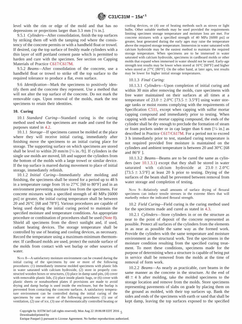
9.5.1 Cylinders—After consolidation, finish the top surfacesby striking them off with the tamping rod where the consis-tency of the concrete permits or with a handheld float or trowel.If desired, cap the top surface of freshly made cylinders with athin layer of stiff portland cement paste which is permitted toharden and cure with the specimen. See section on CappingMaterials of Practice C617/C617M.
9.5.2 Beams—After consolidation of the concrete, use ahandheld float or trowel to strike off the top surface to therequired tolerance to produce a flat, even surface.
9.6 Identification—Mark the specimens to positively iden-tify them and the concrete they represent. Use a method thatwill not alter the top surface of the concrete. Do not mark theremovable caps. Upon removal of the molds, mark the testspecimens to retain their identities.
10. Curing
10.1 Standard Curing—Standard curing is the curingmethod used when the specimens are made and cured for thepurposes stated in 4.2.
10.1.1 Storage—If specimens cannot be molded at the placewhere they will receive initial curing, immediately afterfinishing move the specimens to an initial curing place forstorage. The supporting surface on which specimens are storedshall be level to within 20 mm/m [1⁄4 in. ⁄ ft]. If cylinders in thesingle use molds are moved, lift and support the cylinders fromthe bottom of the molds with a large trowel or similar device.If the top surface is marred during movement to place of initialstorage, immediately refinish.
10.1.2 Initial Curing—Immediately after molding andfinishing, the specimens shall be stored for a period up to 48 hin a temperature range from 16 to 27°C [60 to 80°F] and in anenvironment preventing moisture loss from the specimens. Forconcrete mixtures with a specified strength of 40 MPa [6000psi] or greater, the initial curing temperature shall be between20 and 26°C [68 and 78°F]. Various procedures are capable ofbeing used during the initial curing period to maintain thespecified moisture and temperature conditions. An appropriateprocedure or combination of procedures shall be used (Note 8).Shield all specimens from the direct sunlight and, if used,radiant heating devices. The storage temperature shall becontrolled by use of heating and cooling devices, as necessary.Record the temperature using a maximum-minimum thermom-eter. If cardboard molds are used, protect the outside surface ofthe molds from contact with wet burlap or other sources ofwater.
NOTE 8—A satisfactory moisture environment can be created during theinitial curing of the specimens by one or more of the followingprocedures: (1) immediately immerse molded specimens with plastic lidsin water saturated with calcium hydroxide, (2) store in properly con-structed wooden boxes or structures, (3) place in damp sand pits, (4) coverwith removable plastic lids, (5) place inside plastic bags, or (6) cover withplastic sheets or nonabsorbent plates if provisions are made to avoiddrying and damp burlap is used inside the enclosure, but the burlap isprevented from contacting the concrete surfaces. A satisfactory tempera-ture environment can be controlled during the initial curing of thespecimens by one or more of the following procedures: (1) use ofventilation, (2) use of ice, (3) use of thermostatically controlled heating or
cooling devices, or (4) use of heating methods such as stoves or lightbulbs. Other suitable methods may be used provided the requirementslimiting specimen storage temperature and moisture loss are met. Forconcrete mixtures with a specified strength of 40 MPa [6000 psi] orgreater, heat generated during the early ages may raise the temperatureabove the required storage temperature. Immersion in water saturated withcalcium hydroxide may be the easiest method to maintain the requiredstorage temperature. When specimens are to be immersed in watersaturated with calcium hydroxide, specimens in cardboard molds or othermolds that expand when immersed in water should not be used. Early-agestrength test results may be lower when stored at 16°C [60°F] and higherwhen stored at 27°C [80°F]. On the other hand, at later ages, test resultsmay be lower for higher initial storage temperatures.
10.1.3 Final Curing:10.1.3.1 Cylinders—Upon completion of initial curing and
within 30 min after removing the molds, cure specimens withfree water maintained on their surfaces at all times at atemperature of 23.0 6 2.0°C [73.5 6 3.5°F] using water stor-age tanks or moist rooms complying with the requirements ofSpecification C511, except when capping with sulfur mortarcapping compound and immediately prior to testing. Whencapping with sulfur mortar capping compound, the ends of thecylinder shall be dry enough to preclude the formation of steamor foam pockets under or in cap larger than 6 mm [1⁄4 in.] asdescribed in Practice C617/C617M. For a period not to exceed3 h immediately prior to test, standard curing temperature isnot required provided free moisture is maintained on thecylinders and ambient temperature is between 20 and 30°C [68and 86°F ].
10.1.3.2 Beams—Beams are to be cured the same as cylin-ders (see 10.1.3.1) except that they shall be stored in watersaturated with calcium hydroxide at 23.0 6 2.0°C[73.5 6 3.5°F] at least 20 h prior to testing. Drying of thesurfaces of the beam shall be prevented between removal fromwater storage and completion of testing.
NOTE 9—Relatively small amounts of surface drying of flexuralspecimens can induce tensile stresses in the extreme fibers that willmarkedly reduce the indicated flexural strength.
10.2 Field Curing—Field curing is the curing method usedfor the specimens made and cured as stated in 4.3.
10.2.1 Cylinders—Store cylinders in or on the structure asnear to the point of deposit of the concrete represented aspossible. Protect all surfaces of the cylinders from the elementsin as near as possible the same way as the formed work.Provide the cylinders with the same temperature and moistureenvironment as the structural work. Test the specimens in themoisture condition resulting from the specified curing treat-ment. To meet these conditions, specimens made for thepurpose of determining when a structure is capable of being putin service shall be removed from the molds at the time ofremoval of form work.
10.2.2 Beams—As nearly as practicable, cure beams in thesame manner as the concrete in the structure. At the end of48 6 4 h after molding, take the molded specimens to thestorage location and remove from the molds. Store specimensrepresenting pavements of slabs on grade by placing them onthe ground as molded, with their top surfaces up. Bank thesides and ends of the specimens with earth or sand that shall bekept damp, leaving the top surfaces exposed to the specified
C31/C31M − 15a´1
5
Copyright by ASTM Int'l (all rights reserved); Mon Aug 22 18:06:08 EDT 2016Downloaded/printed byEnrique Pasquel () pursuant to License Agreement. No further reproductions authorized.

curing treatment. Store specimens representing structure con-crete as near the point in the structure they represent aspossible, and afford them the same temperature protection andmoisture environment as the structure. At the end of the curingperiod leave the specimens in place exposed to the weather inthe same manner as the structure. Remove all beam specimensfrom field storage and store in water saturated with calciumhydroxide at 23.0 6 2.0°C [73.5 6 3.5°F] for 24 6 4 h imme-diately before time of testing to ensure uniform moisturecondition from specimen to specimen. Observe the precautionsgiven in 10.1.3.2 to guard against drying between time ofremoval from curing to testing.
10.3 Structural Lightweight Concrete Curing—Cure struc-tural lightweight concrete cylinders in accordance with Speci-fication C330/C330M.
11. Transportation of Specimens to Laboratory
11.1 Prior to transporting, cure and protect specimens asrequired in Section 10. Specimens shall not be transported untilat least 8 h after final set. (See Note 10). During transporting,protect the specimens with suitable cushioning material toprevent damage from jarring. During cold weather, protect thespecimens from freezing with suitable insulation material.Prevent moisture loss during transportation by wrapping thespecimens in plastic, wet burlap, by surrounding them with wet
sand, or tight fitting plastic caps on plastic molds. Transporta-tion time shall not exceed 4 h.
NOTE 10—Setting time may be measured by Test Method C403/C403M.
12. Report
12.1 Report the following information to the laboratory thatwill test the specimens:
12.1.1 Identification number,12.1.2 Location of concrete represented by the samples,12.1.3 Date, time and name of individual molding
specimens,12.1.4 Slump, air content, and concrete temperature, test
results and results of any other tests on the fresh concrete andany deviations from referenced standard test methods, and
12.1.5 Curing method. For standard curing method, reportthe initial curing method with maximum and minimum tem-peratures and final curing method. For field curing method,report the location where stored, manner of protection from theelements, temperature and moisture environment, and time ofremoval from molds.
13. Keywords
13.1 beams; casting samples; concrete; curing; cylinders;testing
SUMMARY OF CHANGES
Committee C09 has identified the location of selected changes to this practice since the last issue,C31/C31M–15, that may impact the use of this practice. (Approved Nov. 15, 2015)
(1) Revised 6.2.(2) Added Table 2.
(3) Revised Tables 4 and 5.(4) Added references and notes.
ASTM International takes no position respecting the validity of any patent rights asserted in connection with any item mentionedin this standard. Users of this standard are expressly advised that determination of the validity of any such patent rights, and the riskof infringement of such rights, are entirely their own responsibility.
This standard is subject to revision at any time by the responsible technical committee and must be reviewed every five years andif not revised, either reapproved or withdrawn. Your comments are invited either for revision of this standard or for additional standardsand should be addressed to ASTM International Headquarters. Your comments will receive careful consideration at a meeting of theresponsible technical committee, which you may attend. If you feel that your comments have not received a fair hearing you shouldmake your views known to the ASTM Committee on Standards, at the address shown below.
This standard is copyrighted by ASTM International, 100 Barr Harbor Drive, PO Box C700, West Conshohocken, PA 19428-2959,United States. Individual reprints (single or multiple copies) of this standard may be obtained by contacting ASTM at the aboveaddress or at 610-832-9585 (phone), 610-832-9555 (fax), or [email protected] (e-mail); or through the ASTM website(www.astm.org). Permission rights to photocopy the standard may also be secured from the Copyright Clearance Center, 222Rosewood Drive, Danvers, MA 01923, Tel: (978) 646-2600; http://www.copyright.com/
C31/C31M − 15a´1
6
Copyright by ASTM Int'l (all rights reserved); Mon Aug 22 18:06:08 EDT 2016Downloaded/printed byEnrique Pasquel () pursuant to License Agreement. No further reproductions authorized.

Designation: C39/C39M − 16b
Standard Test Method forCompressive Strength of Cylindrical Concrete Specimens 1
This standard is issued under the fixed designation C39/C39M; the number immediately following the designation indicates the year oforiginal adoption or, in the case of revision, the year of last revision. A number in parentheses indicates the year of last reapproval. Asuperscript epsilon (´) indicates an editorial change since the last revision or reapproval.
This standard has been approved for use by agencies of the U.S. Department of Defense.
1. Scope*
1.1 This test method covers determination of compressivestrength of cylindrical concrete specimens such as moldedcylinders and drilled cores. It is limited to concrete having adensity in excess of 800 kg/m3 [50 lb/ft3].
1.2 The values stated in either SI units or inch-pound unitsare to be regarded separately as standard. The inch-pound unitsare shown in brackets. The values stated in each system maynot be exact equivalents; therefore, each system shall be usedindependently of the other. Combining values from the twosystems may result in non-conformance with the standard.
1.3 This standard does not purport to address all of thesafety concerns, if any, associated with its use. It is theresponsibility of the user of this standard to establish appro-priate safety and health practices and determine the applica-bility of regulatory limitations prior to use.(Warning—Meansshould be provided to contain concrete fragments duringsudden rupture of specimens. Tendency for sudden ruptureincreases with increasing concrete strength and it is more likelywhen the testing machine is relatively flexible. The safetyprecautions given in the Manual are recommended.)
1.4 The text of this standard references notes which provideexplanatory material. These notes shall not be considered asrequirements of the standard.
2. Referenced Documents
2.1 ASTM Standards:2
C31/C31M Practice for Making and Curing Concrete TestSpecimens in the Field
C42/C42M Test Method for Obtaining and Testing DrilledCores and Sawed Beams of Concrete
C192/C192M Practice for Making and Curing Concrete Test
Specimens in the LaboratoryC617/C617M Practice for Capping Cylindrical Concrete
SpecimensC670 Practice for Preparing Precision and Bias Statements
for Test Methods for Construction MaterialsC873/C873M Test Method for Compressive Strength of
Concrete Cylinders Cast in Place in Cylindrical MoldsC1077 Practice for Agencies Testing Concrete and Concrete
Aggregates for Use in Construction and Criteria forTesting Agency Evaluation
C1176/C1176M Practice for Making Roller-CompactedConcrete in Cylinder Molds Using a Vibrating Table
C1231/C1231M Practice for Use of Unbonded Caps inDetermination of Compressive Strength of Hardened Cy-lindrical Concrete Specimens
C1435/C1435M Practice for Molding Roller-CompactedConcrete in Cylinder Molds Using a Vibrating Hammer
E4 Practices for Force Verification of Testing MachinesE74 Practice of Calibration of Force-Measuring Instruments
for Verifying the Force Indication of Testing MachinesManual of Aggregate and Concrete Testing
3. Summary of Test Method
3.1 This test method consists of applying a compressiveaxial load to molded cylinders or cores at a rate which is withina prescribed range until failure occurs. The compressivestrength of the specimen is calculated by dividing the maxi-mum load attained during the test by the cross-sectional area ofthe specimen.
4. Significance and Use
4.1 Care must be exercised in the interpretation of thesignificance of compressive strength determinations by this testmethod since strength is not a fundamental or intrinsic propertyof concrete made from given materials. Values obtained willdepend on the size and shape of the specimen, batching, mixingprocedures, the methods of sampling, molding, and fabricationand the age, temperature, and moisture conditions duringcuring.
4.2 This test method is used to determine compressivestrength of cylindrical specimens prepared and cured in accor-dance with Practices C31/C31M, C192/C192M, C617/C617M,
1 This test method is under the jurisdiction of ASTM Committee C09 onConcrete and Concrete Aggregates and is the direct responsibility of SubcommitteeC09.61 on Testing for Strength.
Current edition approved Aug. 1, 2016. Published August 2016. Originallyapproved in 1921. Last previous edition approved in 2016 as C39/C39M – 16a.DOI: 10.1520/C0039_C0039M-16B.
2 For referenced ASTM standards, visit the ASTM website, www.astm.org, orcontact ASTM Customer Service at [email protected]. For Annual Book of ASTMStandardsvolume information, refer to the standard’s Document Summary page onthe ASTM website.
*A Summary of Changes section appears at the end of this standard
Copyright © ASTM International, 100 Barr Harbor Drive, PO Box C700, West Conshohocken, PA 19428-2959. United States
1
Copyright by ASTM Int'l (all rights reserved); Mon Aug 22 15:03:42 EDT 2016Downloaded/printed byEnrique Pasquel () pursuant to License Agreement. No further reproductions authorized.

C1176/C1176M, C1231/C1231M, and C1435/C1435M, andTest Methods C42/C42M and C873/C873M.
4.3 The results of this test method are used as a basis forquality control of concrete proportioning, mixing, and placingoperations; determination of compliance with specifications;control for evaluating effectiveness of admixtures; and similaruses.
4.4 The individual who tests concrete cylinders for accep-tance testing shall meet the concrete laboratory technicianrequirements of Practice C1077, including an examinationrequiring performance demonstration that is evaluated by anindependent examiner.
NOTE 1—Certification equivalent to the minimum guidelines for ACIConcrete Laboratory Technician, Level I or ACI Concrete StrengthTesting Technician will satisfy this requirement.
5. Apparatus
5.1 Testing Machine—The testing machine shall be of a typehaving sufficient capacity and capable of providing the rates ofloading prescribed in 7.5.
5.1.1 Verify the accuracy of the testing machine in accor-dance with Practices E4, except that the verified loading rangeshall be as required in 5.3. Verification is required:
5.1.1.1 Within 13 months of the last calibration,5.1.1.2 On original installation or immediately after
relocation,5.1.1.3 Immediately after making repairs or adjustments
that affect the operation of the force applying system or thevalues displayed on the load indicating system, except for zeroadjustments that compensate for the mass of bearing blocks orspecimen, or both, or
5.1.1.4 Whenever there is reason to suspect the accuracy ofthe indicated loads.
5.1.2 Design—The design of the machine must include thefollowing features:
5.1.2.1 The machine must be power operated and mustapply the load continuously rather than intermittently, andwithout shock. If it has only one loading rate (meeting therequirements of 7.5), it must be provided with a supplementalmeans for loading at a rate suitable for verification. Thissupplemental means of loading may be power or hand oper-ated.
5.1.2.2 The space provided for test specimens shall be largeenough to accommodate, in a readable position, an elasticcalibration device which is of sufficient capacity to cover thepotential loading range of the testing machine and whichcomplies with the requirements of Practice E74.
NOTE 2—The types of elastic calibration devices most generallyavailable and most commonly used for this purpose are the circularproving ring or load cell.
5.1.3 Accuracy—The accuracy of the testing machine shallbe in accordance with the following provisions:
5.1.3.1 The percentage of error for the loads within theproposed range of use of the testing machine shall not exceed61.0 % of the indicated load.
5.1.3.2 The accuracy of the testing machine shall be verifiedby applying five test loads in four approximately equal
increments in ascending order. The difference between any twosuccessive test loads shall not exceed one third of the differ-ence between the maximum and minimum test loads.
5.1.3.3 The test load as indicated by the testing machine andthe applied load computed from the readings of the verificationdevice shall be recorded at each test point. Calculate the error,E, and the percentage of error, Ep, for each point from thesedata as follows:
E 5 A 2 B (1)
Ep 5 100~A 2 B!/B
where:A = load, kN [lbf] indicated by the machine being verified,
andB = applied load, kN [lbf] as determined by the calibrating
device.
5.1.3.4 The report on the verification of a testing machineshall state within what loading range it was found to conformto specification requirements rather than reporting a blanketacceptance or rejection. In no case shall the loading range bestated as including loads below the value which is 100 timesthe smallest change of load estimable on the load-indicatingmechanism of the testing machine or loads within that portionof the range below 10 % of the maximum range capacity.
5.1.3.5 In no case shall the loading range be stated asincluding loads outside the range of loads applied during theverification test.
5.1.3.6 The indicated load of a testing machine shall not becorrected either by calculation or by the use of a calibrationdiagram to obtain values within the required permissiblevariation.
5.2 The testing machine shall be equipped with two steelbearing blocks with hardened faces (Note 3), one of which is aspherically seated block that will bear on the upper surface ofthe specimen, and the other a solid block on which thespecimen shall rest. Bearing faces of the blocks shall have aminimum dimension at least 3 % greater than the diameter ofthe specimen to be tested. Except for the concentric circlesdescribed below, the bearing faces shall not depart from a planeby more than 0.02 mm [0.001 in.] in any 150 mm [6 in.] ofblocks 150 mm [6 in.] in diameter or larger, or by more than0.02 mm [0.001 in.] in the diameter of any smaller block; andnew blocks shall be manufactured within one half of thistolerance. When the diameter of the bearing face of thespherically seated block exceeds the diameter of the specimenby more than 13 mm [0.5 in.], concentric circles not more than0.8 mm [0.03 in.] deep and not more than 1 mm [0.04 in.] wideshall be inscribed to facilitate proper centering.
NOTE 3—It is desirable that the bearing faces of blocks used forcompression testing of concrete have a Rockwell hardness of not less than55 HRC.
5.2.1 Bottom bearing blocks shall conform to the followingrequirements:
5.2.1.1 The bottom bearing block is specified for the pur-pose of providing a readily machinable surface for mainte-nance of the specified surface conditions (Note 4). The top andbottom surfaces shall be parallel to each other. If the testing
C39/C39M − 16b
2
Copyright by ASTM Int'l (all rights reserved); Mon Aug 22 15:03:42 EDT 2016Downloaded/printed byEnrique Pasquel () pursuant to License Agreement. No further reproductions authorized.

machine is so designed that the platen itself is readily main-tained in the specified surface condition, a bottom block is notrequired. Its least horizontal dimension shall be at least 3 %greater than the diameter of the specimen to be tested.Concentric circles as described in 5.2 are optional on thebottom block.
NOTE 4—The block may be fastened to the platen of the testingmachine.
5.2.1.2 Final centering must be made with reference to theupper spherical block. When the lower bearing block is used toassist in centering the specimen, the center of the concentricrings, when provided, or the center of the block itself must bedirectly below the center of the spherical head. Provision shallbe made on the platen of the machine to assure such a position.
5.2.1.3 The bottom bearing block shall be at least 25 mm [1in.] thick when new, and at least 22.5 mm [0.9 in.] thick afterany resurfacing operations.
5.2.2 The spherically seated bearing block shall conform tothe following requirements:
5.2.2.1 The maximum diameter of the bearing face of thesuspended spherically seated block shall not exceed the valuesgiven below:
Diameter of Maximum DiameterTest Specimens, of Bearing Face,
mm [in.] mm [in.]
50 [2] 105 [4]75 [3] 130 [5]100 [4] 165 [6.5]150 [6] 255 [10]200 [8] 280 [11]
NOTE 5—Square bearing faces are permissible, provided the diameter ofthe largest possible inscribed circle does not exceed the above diameter.
5.2.2.2 The center of the sphere shall coincide with thesurface of the bearing face within a tolerance of 65 % of theradius of the sphere. The diameter of the sphere shall be at least75 % of the diameter of the specimen to be tested.
5.2.2.3 The ball and the socket shall be designed so that thesteel in the contact area does not permanently deform whenloaded to the capacity of the testing machine.
NOTE 6—The preferred contact area is in the form of a ring (describedas “preferred bearing area”) as shown on Fig. 1.
5.2.2.4 At least every six months, or as specified by themanufacturer of the testing machine, clean and lubricate thecurved surfaces of the socket and of the spherical portion of themachine. The lubricant shall be a petroleum-type oil such asconventional motor oil or as specified by the manufacturer ofthe testing machine.
NOTE 7—To ensure uniform seating, the spherically seated head isdesigned to tilt freely as it comes into contact with the top of the specimen.After contact, further rotation is undesirable. Friction between the socketand the spherical portion of the head provides restraint against furtherrotation during loading. Petroleum-type oil such as conventional motor oilhas been shown to permit the necessary friction to develop. Pressure-typegreases can reduce the desired friction and permit undesired rotation of thespherical head and should not be used unless recommended by themanufacturer of the testing machine.
5.2.2.5 If the radius of the sphere is smaller than the radiusof the largest specimen to be tested, the portion of the bearing
face extending beyond the sphere shall have a thickness notless than the difference between the radius of the sphere andradius of the specimen. The least dimension of the bearing faceshall be at least as great as the diameter of the sphere (see Fig.1).
5.2.2.6 The movable portion of the bearing block shall beheld closely in the spherical seat, but the design shall be suchthat the bearing face can be rotated freely and tilted at least 4°in any direction.
5.2.2.7 If the ball portion of the upper bearing block is atwo-piece design composed of a spherical portion and abearing plate, a mechanical means shall be provided to ensurethat the spherical portion is fixed and centered on the bearingplate.
5.3 Load Indication:5.3.1 If the load of a compression machine used in concrete
testing is registered on a dial, the dial shall be provided with agraduated scale that is readable to at least the nearest 0.1 % ofthe full scale load (Note 8). The dial shall be readable within1 % of the indicated load at any given load level within theloading range. In no case shall the loading range of a dial beconsidered to include loads below the value that is 100 timesthe smallest change of load that can be read on the scale. Thescale shall be provided with a graduation line equal to zero andso numbered. The dial pointer shall be of sufficient length toreach the graduation marks; the width of the end of the pointershall not exceed the clear distance between the smallestgraduations. Each dial shall be equipped with a zero adjust-ment located outside the dialcase and easily accessible from thefront of the machine while observing the zero mark and dialpointer. Each dial shall be equipped with a suitable device thatat all times, until reset, will indicate to within 1 % accuracy themaximum load applied to the specimen.
NOTE 8—Readability is considered to be 0.5 mm [0.02 in.] along the arcdescribed by the end of the pointer. Also, one half of a scale interval isreadable with reasonable certainty when the spacing on the load indicatingmechanism is between 1 mm [0.04 in.] and 2 mm [0.06 in.]. When the
NOTE 1—Provision shall be made for holding the ball in the socket andfor holding the entire unit in the testing machine.
FIG. 1 Schematic Sketch of a Typical Spherical Bearing Block
C39/C39M − 16b
3
Copyright by ASTM Int'l (all rights reserved); Mon Aug 22 15:03:42 EDT 2016Downloaded/printed byEnrique Pasquel () pursuant to License Agreement. No further reproductions authorized.

spacing is between 2 and 3 mm [0.06 and 0.12 in.], one third of a scaleinterval is readable with reasonable certainty. When the spacing is 3 mm[0.12 in.] or more, one fourth of a scale interval is readable withreasonable certainty.
5.3.2 If the testing machine load is indicated in digital form,the numerical display must be large enough to be easily read.The numerical increment must be equal to or less than 0.10 %of the full scale load of a given loading range. In no case shallthe verified loading range include loads less than the minimumnumerical increment multiplied by 100. The accuracy of theindicated load must be within 1.0 % for any value displayedwithin the verified loading range. Provision must be made foradjusting to indicate true zero at zero load. There shall beprovided a maximum load indicator that at all times until resetwill indicate within 1 % system accuracy the maximum loadapplied to the specimen.
5.4 Documentation of the calibration and maintenance ofthe testing machine shall be in accordance with PracticeC1077.
6. Specimens
6.1 Specimens shall not be tested if any individual diameterof a cylinder differs from any other diameter of the samecylinder by more than 2 %.
NOTE 9—This may occur when single use molds are damaged ordeformed during shipment, when flexible single use molds are deformedduring molding, or when a core drill deflects or shifts during drilling.
6.2 Prior to testing, neither end of test specimens shalldepart from perpendicularity to the axis by more than 0.5°(approximately equivalent to 1 mm in 100 mm [0.12 in. in 12in.]). The ends of compression test specimens that are not planewithin 0.050 mm [0.002 in.] shall be sawed or ground to meetthat tolerance, or capped in accordance with either PracticeC617/C617M or, when permitted, Practice C1231/C1231M.The diameter used for calculating the cross-sectional area ofthe test specimen shall be determined to the nearest 0.25 mm[0.01 in.] by averaging two diameters measured at right anglesto each other at about midheight of the specimen.
6.3 The number of individual cylinders measured for deter-mination of average diameter is not prohibited from beingreduced to one for each ten specimens or three specimens perday, whichever is greater, if all cylinders are known to havebeen made from a single lot of reusable or single-use moldswhich consistently produce specimens with average diameterswithin a range of 0.5 mm [0.02 in.]. When the averagediameters do not fall within the range of 0.5 mm [0.02 in.] orwhen the cylinders are not made from a single lot of molds,each cylinder tested must be measured and the value used incalculation of the unit compressive strength of that specimen.When the diameters are measured at the reduced frequency, thecross-sectional areas of all cylinders tested on that day shall becomputed from the average of the diameters of the three ormore cylinders representing the group tested that day.
6.4 If the purchaser of the testing services or the specifier ofthe tests requests measurement of density of test specimens,determine the mass of specimens before capping. Remove anysurface moisture with a towel and measure the mass of the
specimen using a balance or scale that is accurate to within0.3 % of the mass being measured. Measure the length of thespecimen to the nearest 1 mm [0.05 in.] at three locationsspaced evenly around the circumference. Compute the averagelength and record to the nearest 1 mm [0.05 in.]. Alternatively,determine the cylinder density by weighing the cylinder in airand then submerged under water at 23.0 6 2.0 °C [73.5 6 3.5°F], and computing the volume according to 8.3.1.
6.5 When density determination is not required and thelength to diameter ratio is less than 1.8 or more than 2.2,measure the length of the specimen to the nearest 0.05 D.
7. Procedure
7.1 Compression tests of moist-cured specimens shall bemade as soon as practicable after removal from moist storage.
7.2 Test specimens shall be kept moist by any convenientmethod during the period between removal from moist storageand testing. They shall be tested in the moist condition.
7.3 All specimens for a given test age shall be broken withinthe time tolerances as follows:
Test Age Permissible Tolerance
24 h ±0.5 h or 2.1 %3 days ±2 h or 2.8 %7 days ±6 h or 3.6 %
28 days ±20 h or 3.0 %90 days ±2 days or 2.2 %
7.3.1 Unless otherwise specified by the specifier of tests, forthis test method the test age shall start at the beginning ofcasting specimens.
7.4 Placing the Specimen—Place the plain (lower) bearingblock, with its hardened face up, on the table or platen of thetesting machine directly under the spherically seated (upper)bearing block. Wipe clean the bearing faces of the upper andlower bearing blocks and of the test specimen and place the testspecimen on the lower bearing block. If using unbonded caps,wipe clean the bearing surfaces of the retaining ring or ringsand center the unbonded cap or caps on the cylinder. Carefullyalign the axis of the specimen with the center of thrust of thespherically seated block.
7.4.1 Zero Verification and Block Seating—Prior to testingthe specimen, verify that the load indicator is set to zero. Incases where the indicator is not properly set to zero, adjust theindicator (Note 10). After placing the specimen in the machinebut prior to applying the load on the specimen, tilt the movableportion of the spherically seated block gently by hand so thatthe bearing face appears to be parallel to the top of the testspecimen.
NOTE 10—The technique used to verify and adjust load indicator to zerowill vary depending on the machine manufacturer. Consult your owner’smanual or compression machine calibrator for the proper technique.
7.4.2 Verification of Alignment When Using UnbondedCaps—If using unbonded caps, verify the alignment of thespecimen after application of load, but before reaching 10 % ofthe anticipated specimen strength. Check to see that the axis ofthe cylinder does not depart from vertical by more than 0.5°(Note 11) and that the ends of the cylinder are centered withinthe retaining rings. If the cylinder alignment does not meet
C39/C39M − 16b
4
Copyright by ASTM Int'l (all rights reserved); Mon Aug 22 15:03:42 EDT 2016Downloaded/printed byEnrique Pasquel () pursuant to License Agreement. No further reproductions authorized.
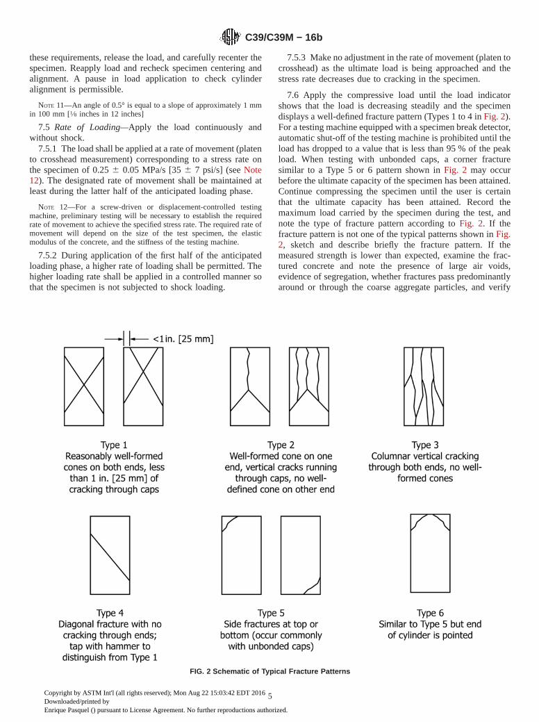
these requirements, release the load, and carefully recenter thespecimen. Reapply load and recheck specimen centering andalignment. A pause in load application to check cylinderalignment is permissible.
NOTE 11—An angle of 0.5° is equal to a slope of approximately 1 mmin 100 mm [1⁄8 inches in 12 inches]
7.5 Rate of Loading—Apply the load continuously andwithout shock.
7.5.1 The load shall be applied at a rate of movement (platento crosshead measurement) corresponding to a stress rate onthe specimen of 0.25 6 0.05 MPa/s [35 6 7 psi/s] (see Note12). The designated rate of movement shall be maintained atleast during the latter half of the anticipated loading phase.
NOTE 12—For a screw-driven or displacement-controlled testingmachine, preliminary testing will be necessary to establish the requiredrate of movement to achieve the specified stress rate. The required rate ofmovement will depend on the size of the test specimen, the elasticmodulus of the concrete, and the stiffness of the testing machine.
7.5.2 During application of the first half of the anticipatedloading phase, a higher rate of loading shall be permitted. Thehigher loading rate shall be applied in a controlled manner sothat the specimen is not subjected to shock loading.
7.5.3 Make no adjustment in the rate of movement (platen tocrosshead) as the ultimate load is being approached and thestress rate decreases due to cracking in the specimen.
7.6 Apply the compressive load until the load indicatorshows that the load is decreasing steadily and the specimendisplays a well-defined fracture pattern (Types 1 to 4 in Fig. 2).For a testing machine equipped with a specimen break detector,automatic shut-off of the testing machine is prohibited until theload has dropped to a value that is less than 95 % of the peakload. When testing with unbonded caps, a corner fracturesimilar to a Type 5 or 6 pattern shown in Fig. 2 may occurbefore the ultimate capacity of the specimen has been attained.Continue compressing the specimen until the user is certainthat the ultimate capacity has been attained. Record themaximum load carried by the specimen during the test, andnote the type of fracture pattern according to Fig. 2. If thefracture pattern is not one of the typical patterns shown in Fig.2, sketch and describe briefly the fracture pattern. If themeasured strength is lower than expected, examine the frac-tured concrete and note the presence of large air voids,evidence of segregation, whether fractures pass predominantlyaround or through the coarse aggregate particles, and verify
FIG. 2 Schematic of Typical Fracture Patterns
C39/C39M − 16b
5
Copyright by ASTM Int'l (all rights reserved); Mon Aug 22 15:03:42 EDT 2016Downloaded/printed byEnrique Pasquel () pursuant to License Agreement. No further reproductions authorized.

end preparations were in accordance with Practice C617/C617M or Practice C1231/C1231M.
8. Calculation
8.1 Calculate the compressive strength of the specimen bydividing the maximum load resisted by the specimen during thetest by the average cross-sectional area determined as de-scribed in Section 6.
8.2 If the specimen length to diameter ratio is 1.75 or less,correct the result obtained in 8.1 by multiplying by theappropriate correction factor shown in the following table Note13:
L/D: 1.75 1.50 1.25 1.00Factor: 0.98 0.96 0.93 0.87
Use interpolation to determine correction factors for L/Dvalues between those given in the table.
NOTE 13—Correction factors depend on various conditions such asmoisture condition, strength level, and elastic modulus. Average values aregiven in the table. These correction factors apply to low-density concreteweighing between 1600 and 1920 kg/m3 [100 and 120 lb/ft3] and tonormal-density concrete. They are applicable to concrete dry or soaked atthe time of loading and for nominal concrete strengths from 14 to 42 MPa[2000 to 6000 psi]. For strengths higher than 42 MPa [6000 psi] correctionfactors may be larger than the values listed above3.
8.3 When required, calculate the density of the specimen tothe nearest 10 kg/m3 [1 lb/ft3] as follows:
Density5WV
(2)
where:W = mass of specimen, kg [lb], andV = volume of specimen computed from the average diam-
eter and average length or from weighing the cylinder inair and submerged, m3 [ft3].
8.3.1 When the volume is determined from submergedweighing, calculate the volume as follows:
V 5W 2 Ws
γw
(3)
where:Ws = apparent mass of submerged specimen, kg [lb], andγw = density of water at 23 °C [73.5 °F] = 997.5 kg/m3
[62.27 lbs ⁄ft3].
9. Report
9.1 Report the following information:9.1.1 Identification number,9.1.2 Average measured diameter (and measured length, if
outside the range of 1.8 D to 2.2 D), in millimetres [inches],9.1.3 Cross-sectional area, in square millimetres [square
inches],9.1.4 Maximum load, in kilonewtons [pounds-force],9.1.5 Compressive strength rounded to the nearest 0.1 MPa
[10 psi],
9.1.6 If the average of two or more companion cylinderstested at the same age is reported, calculate the averagecompressive strength using the unrounded individual compres-sive strength values. Report the average compressive-strengthrounded to the nearest 0.1 MPa [10 psi].
9.1.7 Type of fracture (see Fig. 2),9.1.8 Defects in either specimen or caps,9.1.9 Age of specimen, and9.1.10 If determined, the density to the nearest 10 kg/m3 [1
lb/ft3].
10. Precision and Bias
10.1 Precision10.1.1 Single-Operator Precision—The following table pro-
vides the single-operator precision of tests of 150 by 300 mm[6 by 12 in.] and 100 by 200 mm [4 by 8 in.] cylinders madefrom a well-mixed sample of concrete under laboratory con-ditions and under field conditions (see 10.1.2).
Coefficient ofVariation4
Acceptable Range4 ofIndividual Cylinder Strengths2 cylinders 3 cylinders
150 by 300 mm[6 by 12 in.]
Laboratory conditions 2.4 % 6.6 % 7.8 %Field conditions 2.9 % 8.0 % 9.5 %
100 by 200 mm[4 by 8 in.]
Laboratory conditions 3.2 % 9.0 % 10.6 %
10.1.2 The single-operator coefficient of variation repre-sents the expected variation of measured strength of compan-ion cylinders prepared from the same sample of concrete andtested by one laboratory at the same age. The values given forthe single-operator coefficient of variation of 150 by 300 mm[6 by 12 in.] cylinders are applicable for compressive strengthsbetween 15 to 55 MPa [2000 to 8000 psi] and those for 100 by200 mm [4 by 8 in.] cylinders are applicable for compressivestrengths between 17 to 32 MPa [2500 and 4700 psi]. Thesingle-operator coefficients of variation for 150 by 300 mm [6by 12 in.] cylinders are derived from CCRL concrete profi-ciency sample data for laboratory conditions and a collection of1265 test reports from 225 commercial testing laboratories in1978.5 The single-operator coefficient of variation of 100 by200 mm [4 by 8 in.] cylinders are derived from CCRL concreteproficiency sample data for laboratory conditions.
10.1.3 Multilaboratory Precision—The multi-laboratory co-efficient of variation for compressive strength test results of150 by 300 mm [6 by 12 in.] cylinders has been found to be5.0 %4; therefore, the results of properly conducted tests bytwo laboratories on specimens prepared from the same sampleof concrete are not expected to differ by more than 14 %4 of theaverage (see Note 14). A strength test result is the average oftwo cylinders tested at the same age.
NOTE 14—The multilaboratory precision does not include variationsassociated with different operators preparing test specimens from split orindependent samples of concrete. These variations are expected to
3 Bartlett, F.M. and MacGregor, J.G., “Effect of Core Length-to-Diameter Ratioon Concrete Core Strength,”ACI Materials Journal, Vol 91, No. 4, July-August,1994, pp. 339–348.
4 These numbers represent respectively the (1s %) and (d2s %) limits asdescribed in Practice C670.
5 Supporting data have been filed at ASTM International Headquarters and maybe obtained by requesting Research Report RR:C09-1006. Contact ASTM CustomerService at [email protected].
C39/C39M − 16b
6
Copyright by ASTM Int'l (all rights reserved); Mon Aug 22 15:03:42 EDT 2016Downloaded/printed byEnrique Pasquel () pursuant to License Agreement. No further reproductions authorized.

increase the multilaboratory coefficient of variation.
10.1.4 The multilaboratory data were obtained from sixseparate organized strength testing round robin programswhere 150 by 300 mm [6 by 12 in.] cylindrical specimens wereprepared at a single location and tested by different laborato-ries. The range of average strength from these programs was17.0 to 90 MPa [2500 to 13 000 psi].
NOTE 15—Subcommittee C09.61 will continue to examine recentconcrete proficiency sample data and field test data and make revisions to
precisions statements when data indicate that they can be extended tocover a wider range of strengths and specimen sizes.
10.2 Bias—Since there is no accepted reference material, nostatement on bias is being made.
11. Keywords
11.1 concrete core; concrete cylinder; concrete specimen;concrete strength; compressive strength; core; cylinder; drilledcore; strength
SUMMARY OF CHANGES
Committee C09 has identified the location of selected changes to this standard since the last issue(C39/C39M–16a) that may impact the use of this standard. (Approved August 1, 2016.)
(1) Revised 7.3 and added 7.3.1.
ASTM International takes no position respecting the validity of any patent rights asserted in connection with any item mentionedin this standard. Users of this standard are expressly advised that determination of the validity of any such patent rights, and the riskof infringement of such rights, are entirely their own responsibility.
This standard is subject to revision at any time by the responsible technical committee and must be reviewed every five years andif not revised, either reapproved or withdrawn. Your comments are invited either for revision of this standard or for additional standardsand should be addressed to ASTM International Headquarters. Your comments will receive careful consideration at a meeting of theresponsible technical committee, which you may attend. If you feel that your comments have not received a fair hearing you shouldmake your views known to the ASTM Committee on Standards, at the address shown below.
This standard is copyrighted by ASTM International, 100 Barr Harbor Drive, PO Box C700, West Conshohocken, PA 19428-2959,United States. Individual reprints (single or multiple copies) of this standard may be obtained by contacting ASTM at the aboveaddress or at 610-832-9585 (phone), 610-832-9555 (fax), or [email protected] (e-mail); or through the ASTM website(www.astm.org). Permission rights to photocopy the standard may also be secured from the Copyright Clearance Center, 222Rosewood Drive, Danvers, MA 01923, Tel: (978) 646-2600; http://www.copyright.com/
C39/C39M − 16b
7
Copyright by ASTM Int'l (all rights reserved); Mon Aug 22 15:03:42 EDT 2016Downloaded/printed byEnrique Pasquel () pursuant to License Agreement. No further reproductions authorized.

Designation: C172/C172M − 14a
Standard Practice forSampling Freshly Mixed Concrete1
This standard is issued under the fixed designation C172/C172M; the number immediately following the designation indicates the yearof original adoption or, in the case of revision, the year of last revision. A number in parentheses indicates the year of last reapproval.A superscript epsilon (´) indicates an editorial change since the last revision or reapproval.
1. Scope*
1.1 This practice covers procedures for obtaining represen-tative samples of fresh concrete as delivered to the project siteon which tests are to be performed to determine compliancewith quality requirements of the specifications under which theconcrete is furnished (Note 1). The practice includes samplingfrom stationary, paving and truck mixers, and from agitatingand nonagitating equipment used to transport central-mixedconcrete and from continuous mixing equipment as describedin Specification C685/C685M.
1.2 The values stated in either SI units or inch-pound unitsare to be regarded separately as standard. The values stated ineach system may not be exact equivalents; therefore, eachsystem shall be used independently of the other. Combiningvalues from the two systems may result in non-conformancewith the standard.
NOTE 1—Composite samples are required by this practice, unlessspecifically excepted by procedures governing the tests to be performedsuch as tests to determine uniformity of consistency and mixer efficiency.Procedures used to select the specific test batches are not described in thispractice, but it is recommended that random sampling be used todetermine overall specification compliance.
1.3 This practice also covers the procedures to be used forpreparing a sample of concrete for further testing where it isdesirable or necessary to remove the aggregate larger than adesignated size. This removal of larger aggregate particles ispreferably accomplished by wet-sieving.
1.4 The text of this standard references notes and footnoteswhich provide explanatory material and shall not be consideredas requirements of the practice.
1.5 This standard does not purport to address all of thesafety concerns, if any, associated with its use. It is theresponsibility of the user of this standard to establish appro-priate safety and health practices and determine the applica-bility of regulatory limitations prior to use. (Warning—Fresh
hydraulic cementitious mixtures are caustic and may causechemical burns to skin and tissue upon prolonged exposure.2)
2. Referenced Documents
2.1 ASTM Standards:3
E11 Specification for Woven Wire Test Sieve Cloth and TestSieves
C685/C685M Specification for Concrete Made by Volumet-ric Batching and Continuous Mixing
3. Significance and Use
3.1 This practice is intended to provide standard require-ments and procedures for sampling freshly mixed concretefrom different containers used in the production or transporta-tion of concrete. The detailed requirements as to materials,mixtures, air content, temperature, number of specimens,slump, interpretation of results, and precision and bias are inspecific test methods.
4. Sampling
4.1 The elapsed time shall not exceed 15 min. betweenobtaining the first and final portions of the composite sample.
4.1.1 Transport the individual samples to the place wherefresh concrete tests are to be performed or where test speci-mens are to be molded. They shall be combined and remixedwith a shovel the minimum amount necessary to ensureuniformity and compliance with the maximum time limitsspecified in 4.1.2.
4.1.2 Start tests for slump, temperature, and air contentwithin 5 min after obtaining the final portion of the compositesample. Complete these tests expeditiously. Start moldingspecimens for strength tests within 15 min after fabricating thecomposite sample. Expeditiously obtain and use the sampleand protect the sample from the sun, wind, and other sources ofrapid evaporation, and from contamination.
1 This practice is under the jurisdiction of ASTM Committee C09 on Concreteand Concrete Aggregates and is the direct responsibility of Subcommittee C09.60 onTesting Fresh Concrete.
Current edition approved Oct. 1, 2014. Published November 2014. Originallyapproved in 1942. Last previous edition approved in 2014 as C172–14. DOI:10.1520/C0172_C0172M-14A.
2 Section on Safety Precautions, Manual of Aggregate and Concrete Testing,Annual Book of ASTM Standards, Vol 04.02.
3 For referenced ASTM standards, visit the ASTM website, www.astm.org, orcontact ASTM Customer Service at [email protected]. For Annual Book of ASTMStandards volume information, refer to the standard’s Document Summary page onthe ASTM website.
*A Summary of Changes section appears at the end of this standard
Copyright © ASTM International, 100 Barr Harbor Drive, PO Box C700, West Conshohocken, PA 19428-2959. United States
1
Copyright by ASTM Int'l (all rights reserved); Mon Feb 9 17:11:12 EST 2015Downloaded/printed byEnrique Pasquel () pursuant to License Agreement. No further reproductions authorized.

5. Procedure
5.1 Size of Sample—Make the samples to be used forstrength tests a minimum of 28 L [1 ft3]. Smaller samples arenot prohibited for routine air content, temperature, and slumptests. The size of the samples shall be dictated by the maximumaggregate size.
5.2 The procedures used in sampling shall include the use ofevery precaution that will assist in obtaining samples that aretruly representative of the nature and condition of concretesampled as follows:
NOTE 2—Sampling should normally be performed as the concrete isdelivered from the mixer to the conveying vehicle used to transport theconcrete to the forms; however, specifications may require other points ofsampling, such as the discharge of a concrete pump.
5.2.1 Sampling from Stationary Mixers, Except PavingMixers—Sample the concrete by collecting two or moreportions taken at regularly spaced intervals during discharge ofthe middle portion of the batch. Obtain these portions withinthe time limit specified in Section 4. Combine into onecomposite sample for testing purposes. Do not obtain portionsof the composite sample from the very first or last part of thebatch discharge (Note 3). Perform sampling by passing areceptacle completely through the discharge stream, or bycompletely diverting the discharge into a sample container. Ifdischarge of the concrete is too rapid to divert the completedischarge stream, discharge the concrete into a container ortransportation unit sufficiently large to accommodate the entirebatch and then accomplish the sampling in the same manner asgiven above. Take care not to restrict the flow of concrete fromthe mixer, container, or transportation unit so as to causesegregation. These requirements apply to both tilting andnontilting mixers.
NOTE 3—No samples should be taken before 10 % or after 90 % of thebatch has been discharged. Due to the difficulty of determining the actualquantity of concrete discharged, the intent is to provide samples that arerepresentative of widely separated portions, but not the beginning and theend of the load.
5.2.2 Sampling from Paving Mixers—Sample the concreteafter the contents of the paving mixer have been discharged.Obtain samples from at least five different portions of the pileand combine them into one composite sample for test purposes.Avoid contamination with subgrade material or prolongedcontact with and absorptive subgrade. To preclude contamina-tion or absorption by the subgrade, sample the concrete byplacing three shallow containers on the subgrade and discharg-ing the concrete across the container. Combine the samples soobtained into one composite sample for test purposes. Thecontainers shall be of a size sufficient to provide a compositesample size that is in agreement with the maximum aggregatesize.
NOTE 4—In some instances, the containers may have to be supportedabove the subgrade to prevent displacement during discharge.
5.2.3 Sampling from Revolving Drum Truck Mixers orAgitators—Sample the concrete by collecting two or moreportions taken at regularly spaced intervals during discharge ofthe middle portion of the batch. Take the samples so obtainedwithin the time limit specified in Section 4 and combine them
into one composite sample for test purposes. In any case do notobtain samples until after all of the water and any admixtureshave been added to the mixer; also do not obtain samples fromthe very first or last portions of the batch discharge (Note 3).Sample by repeatedly passing a receptacle through the entiredischarge stream or by completely diverting the discharge intoa sample container. Regulate the rate of discharge of the batchby the rate of revolution of the drum and not by the size of thegate opening.
5.2.4 Sampling from Continuous Mixers—Sample the con-crete after the discharge of at least 140 L [5 ft3] of concrete,following all mixture proportioning adjustments. Sample theconcrete at the frequency specified by collecting two or moreportions taken at regularly spaced intervals during discharge ofthe concrete. Take the portions so obtained within the timelimit specified in Section 4, and combine them into onecomposite sample for test purposes. Do not obtain samplesfrom the very first or last portions of a mixer’s continuousdischarge (Note 3). Sample by repeatedly passing a receptaclethrough the entire discharge stream or by completely divertingthe discharge into a sample container. After obtaining thecomposite sample, wait a minimum of 2 minutes and amaximum of 5 minutes before beginning tests (Note 5).
NOTE 5—The waiting period prior to commencing the testing is neededbecause the mix water is input only seconds before discharge from thecontinuous mixer.
5.2.5 Sampling from Open-Top Truck Mixers, Agitators,Nonagitating Equipment, or Other Types of Open-TopContainers—Take samples by whichever of the proceduresdescribed in 5.2.1, 5.2.2, or 5.2.3 is most applicable under thegiven conditions.
6. Additional Procedure for Large Maximum SizeAggregate Concrete
6.1 When the concrete contains aggregate larger than thatappropriate for the size of the molds or equipment to be used,wet-sieve the sample as described below except performdensity (unit weight) tests for use in yield computations on thefull mix.
NOTE 6—The effect of wet-sieving on the test results should beconsidered. For example, wet-sieving concrete causes the loss of a smallamount of air due to additional handling. The air content of the wet-sievedfraction of concrete is greater than that of the total concrete because thelarger size aggregate which is removed does not contain air. The apparentstrength of wet-sieved concrete in smaller specimens is usually greaterthan that of the total concrete in larger appropriate size specimens. Theeffect of these differences may need to be considered or determined bysupplementary testing for quality control or test result evaluation pur-poses.
6.2 Definition:6.2.1 wet-sieving concrete—the process of removing aggre-
gate larger than a designated size from the fresh concrete bysieving it on a sieve of the designated size.
6.3 Apparatus:6.3.1 Sieves, as designated, conforming to Specification
E11.6.3.2 Receptacle—A container of suitable size having a
nonabsorbent surface.
C172/C172M − 14a
2
Copyright by ASTM Int'l (all rights reserved); Mon Feb 9 17:11:12 EST 2015Downloaded/printed byEnrique Pasquel () pursuant to License Agreement. No further reproductions authorized.

6.3.3 Wet-Sieving Equipment—Equipment for wet-sievingconcrete shall be a sieve as noted in 6.3.1 of suitable size andconveniently arranged and supported so that one can shake itrapidly by either hand or mechanical means. Generally, ahorizontal back and forth motion is preferred. The equipmentshall be capable of rapidly and effectively removing thedesignated size of aggregate.
6.3.4 Hand Tools—Shovels, hand scoops, plasteringtrowels, and rubber gloves as required.
6.4 Procedure:6.4.1 Wet-Sieving—After sampling the concrete, pass the
concrete over the designated sieve and remove and discard theaggregate retained. This shall be done before remixing. Shakeor vibrate the sieve by hand or mechanical means until noundersize material remains on the sieve. Mortar adhering to the
aggregate retained on the sieve shall not be wiped from itbefore it is discarded. Place only enough concrete on the sieveat any one time so that after sieving, the thickness of the layerof retained aggregate is not more than one particle thick. Theconcrete which passes the sieve shall fall into a batch pan ofsuitable size which has been dampened before use or onto aclean, moist, nonabsorbent surface. Scrape any mortar adher-ing to the sides of the wet-sieving equipment into the batch.After removing the larger aggregate particles by wet-sievingremix the batch with a shovel the minimum amount necessaryto ensure uniformity and proceed testing immediately.
7. Keywords
7.1 air content; batch; composite sample; concrete; slump;temperature; wet-sieving
SUMMARY OF CHANGES
Committee C09 has identified the location of selected changes to this practice since the last issue, C172–14,that may impact the use of this practice. (Approved October 1, 2014)
(1) Revised first sentence of 5.2.4.
ASTM International takes no position respecting the validity of any patent rights asserted in connection with any item mentionedin this standard. Users of this standard are expressly advised that determination of the validity of any such patent rights, and the riskof infringement of such rights, are entirely their own responsibility.
This standard is subject to revision at any time by the responsible technical committee and must be reviewed every five years andif not revised, either reapproved or withdrawn. Your comments are invited either for revision of this standard or for additional standardsand should be addressed to ASTM International Headquarters. Your comments will receive careful consideration at a meeting of theresponsible technical committee, which you may attend. If you feel that your comments have not received a fair hearing you shouldmake your views known to the ASTM Committee on Standards, at the address shown below.
This standard is copyrighted by ASTM International, 100 Barr Harbor Drive, PO Box C700, West Conshohocken, PA 19428-2959,United States. Individual reprints (single or multiple copies) of this standard may be obtained by contacting ASTM at the aboveaddress or at 610-832-9585 (phone), 610-832-9555 (fax), or [email protected] (e-mail); or through the ASTM website(www.astm.org). Permission rights to photocopy the standard may also be secured from the Copyright Clearance Center, 222Rosewood Drive, Danvers, MA 01923, Tel: (978) 646-2600; http://www.copyright.com/
C172/C172M − 14a
3Copyright by ASTM Int'l (all rights reserved); Mon Feb 9 17:11:12 EST 2015Downloaded/printed byEnrique Pasquel () pursuant to License Agreement. No further reproductions authorized.
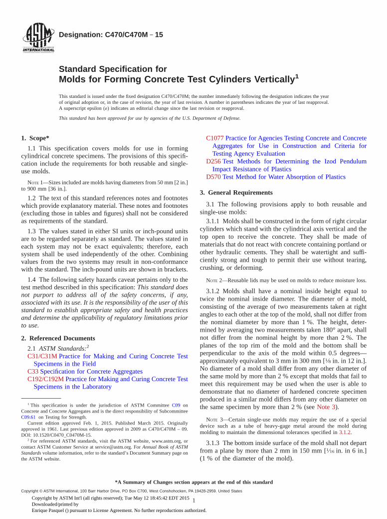
Designation: C470/C470M − 15
Standard Specification forMolds for Forming Concrete Test Cylinders Vertically 1
This standard is issued under the fixed designation C470/C470M; the number immediately following the designation indicates the yearof original adoption or, in the case of revision, the year of last revision. A number in parentheses indicates the year of last reapproval.A superscript epsilon (´) indicates an editorial change since the last revision or reapproval.
This standard has been approved for use by agencies of the U.S. Department of Defense.
1. Scope*
1.1 This specification covers molds for use in formingcylindrical concrete specimens. The provisions of this specifi-cation include the requirements for both reusable and single-use molds.
NOTE 1—Sizes included are molds having diameters from 50 mm [2 in.]to 900 mm [36 in.].
1.2 The text of this standard references notes and footnoteswhich provide explanatory material. These notes and footnotes(excluding those in tables and figures) shall not be consideredas requirements of the standard.
1.3 The values stated in either SI units or inch-pound unitsare to be regarded separately as standard. The values stated ineach system may not be exact equivalents; therefore, eachsystem shall be used independently of the other. Combiningvalues from the two systems may result in non-conformancewith the standard. The inch-pound units are shown in brackets.
1.4 The following safety hazards caveat pertains only to thetest method described in this specification: This standard doesnot purport to address all of the safety concerns, if any,associated with its use. It is the responsibility of the user of thisstandard to establish appropriate safety and health practicesand determine the applicability of regulatory limitations priorto use.
2. Referenced Documents
2.1 ASTM Standards:2
C31/C31M Practice for Making and Curing Concrete TestSpecimens in the Field
C33 Specification for Concrete AggregatesC192/C192M Practice for Making and Curing Concrete Test
Specimens in the Laboratory
C1077 Practice for Agencies Testing Concrete and ConcreteAggregates for Use in Construction and Criteria forTesting Agency Evaluation
D256 Test Methods for Determining the Izod PendulumImpact Resistance of Plastics
D570 Test Method for Water Absorption of Plastics
3. General Requirements
3.1 The following provisions apply to both reusable andsingle-use molds:
3.1.1 Molds shall be constructed in the form of right circularcylinders which stand with the cylindrical axis vertical and thetop open to receive the concrete. They shall be made ofmaterials that do not react with concrete containing portland orother hydraulic cements. They shall be watertight and suffi-ciently strong and tough to permit their use without tearing,crushing, or deforming.
NOTE 2—Reusable lids may be used on molds to reduce moisture loss.
3.1.2 Molds shall have a nominal inside height equal totwice the nominal inside diameter. The diameter of a mold,consisting of the average of two measurements taken at rightangles to each other at the top of the mold, shall not differ fromthe nominal diameter by more than 1 %. The height, deter-mined by averaging two measurements taken 180° apart, shallnot differ from the nominal height by more than 2 %. Theplanes of the top rim of the mold and the bottom shall beperpendicular to the axis of the mold within 0.5 degrees—approximately equivalent to 3 mm in 300 mm [1⁄8 in. in 12 in.].No diameter of a mold shall differ from any other diameter ofthe same mold by more than 2 % except that molds that fail tomeet this requirement may be used when the user is able todemonstrate that no diameter of hardened concrete specimenproduced in a similar mold differs from any other diameter onthe same specimen by more than 2 % (see Note 3).
NOTE 3—Certain single-use molds may require the use of a specialdevice such as a tube of heavy-gage metal around the mold duringmolding to maintain the dimensional tolerances specified in 3.1.2.
3.1.3 The bottom inside surface of the mold shall not departfrom a plane by more than 2 mm in 150 mm [1⁄16 in. in 6 in.](1 % of the diameter of the mold).
1 This specification is under the jurisdiction of ASTM Committee C09 onConcrete and Concrete Aggregates and is the direct responsibility of SubcommitteeC09.61 on Testing for Strength.
Current edition approved Feb. 1, 2015. Published March 2015. Originallyapproved in 1961. Last previous edition approved in 2009 as C470/C470M – 09.DOI: 10.1520/C0470_C0470M-15.
2 For referenced ASTM standards, visit the ASTM website, www.astm.org, orcontact ASTM Customer Service at [email protected]. For Annual Book of ASTMStandardsvolume information, refer to the standard’s Document Summary page onthe ASTM website.
*A Summary of Changes section appears at the end of this standard
Copyright © ASTM International, 100 Barr Harbor Drive, PO Box C700, West Conshohocken, PA 19428-2959. United States
1Copyright by ASTM Int'l (all rights reserved); Tue May 12 18:45:42 EDT 2015Downloaded/printed byEnrique Pasquel () pursuant to License Agreement. No further reproductions authorized.

4. Reusable Molds
4.1 Reusable molds are those which are designed to be usedmore than a single time. Reusable molds shall be made ofnonabsorptive materials, and constructed as either one piece orseveral pieces (see Note 4).
4.2 Reusable molds shall be provided with a closure or baseon the lower end at right angles to the axis of the cylinder.Molds may be single piece molds or made from castings witha separate detachable base plate or a base that is an integral partof the sidewall. The mold shall be either coated or made of amaterial that will prevent adherence to the concrete. At the timeof use, molds shall not leak water. An inside fillet, if any, at thebottom of the side wall shall have an indentation around thecircumference no more than 3 mm [1⁄8 in.] in the verticaldirection or no more than 5 mm [3⁄16 in.] in the horizontaldirection.
4.3 Reusable molds shall be tested for water leakage asdescribed in 6.4, for resistance to damage as described in 6.3.1,and for dimensional stability in accordance with 3.1.2 and 3.1.3initially and after every 50 uses or every six months, whichevercomes first.
NOTE 4—Satisfactory molds can be made from lengths of steel tubingor pipe that is slit on one side parallel to the axis and fitted with a meansof closing the vertical slit as well as a means of attaching a base plate. Therequired dimensional tolerances must be maintained after slitting,clamping, and attaching the base plate. Other nonabsorptive materialswhich have been used include iron, brass, steel, and various plastics.Although aluminum and magnesium alloys have been used, some of thesealloys may be reactive with cement constituents and are thereforeunacceptable.
5. Single-Use Molds
5.1 Single-use molds are molds designed to be used onceand discarded. They are permitted to be made of sheet metal,plastic, suitably treated paper products, or other materials andshall conform to the requirements of this specification.
5.2 Physical Requirements—The molds as prepared for useshall comply with the following:
5.2.1 Water Leakage—When tested as described in Section6, there shall be no visible leakage.
5.2.2 Absorptivity—When tested as described in Section 6,the absorption shall not exceed the values given in Table 1.Intermediate values are proportional to the square of the height.
5.2.3 Elongation—When tested as described in Section 6,the elongation after test shall not exceed 0.2 % of height.
5.3 Single-use Plastic Molds—Molds shall conform to thefollowing additional requirements when plastic is the predomi-nant material used in construction:
5.3.1 Wall Thickness—The side walls shall be of sufficientstiffness to meet the requirements of 3.1 (See Note 5).
NOTE 5—This can be achieved through sufficient side wall thicknessalone, or in combination with a stiffened top.
5.3.2 Bottom Design—The bottom shall be designed so thatit will be flush with the bottom of the sidewall within atolerance of 2 mm [1⁄16 in.]. An inside fillet, if any, at thebottom of the sidewall shall have an indentation around thecircumference no more than 4 mm [1⁄8 in.] in the verticaldirection or no more than 5 mm [3⁄16 in.] in the radial direction.The bottom shall be of adequate rigidity to prevent permanentdeformation when specimens are molded in accordance withthe applicable provisions of Practice C31/C31M or C192/C192M.
5.3.3 Material—The mold manufacturer shall certify that:(1) the plastic material used in molds has a maximum waterabsorption of less than 0.5 % in 24 h when tested in accordancewith Test Method D570; (2) the plastic has an Izod impacttoughness of at least 117 J/m [2.2 ft lb/in.] of notch for a 4 mm[1⁄8 in.] thick specimen tested in accordance with Test MethodsD256; and (3) after being held at 12 °C [10 °F] for 24 h, theplastic shall not fracture when subject to tapping and jarringthat is judged to be typical of what occurs when specimens aremolded in accordance with the applicable provisions of Prac-tice C31/C31M or C192/C192M.
5.4 Paper Molds—When paper or other potentially absorp-tive fiber material is used as the primary structural material inthe construction of the side walls or bottom of the mold, themold shall conform to the following additional requirements:
5.4.1 Side Walls—The side walls of paper molds shall bemade with a minimum of three plies having a combinedthickness of not less than 2 mm [0.070 in.]. Seams on the insideof the mold shall not be open by more than 2 mm [1⁄16 in.].
NOTE 6—The minimum thickness of material used in side walls andbottoms is considered adequate for cylinders up to 150 mm [6 in.] indiameter. For larger cylinders thicker material may be required to meetrequirements of 3.1.
5.4.2 Bottom Caps—The bottom cap of the mold shall bemade of either metal or paper. If metal, it shall not be less than0.23 mm [0.009 in.] in thickness and coated to preventcorrosion (Note 6). It shall be designed so that it will be flushwith the bottom edge of the side wall within a tolerance of 2mm [1⁄16 in.] and the inside crimp, if any, shall produce anindentation around the circumference of the cylinder no morethan 5 mm [3⁄16 in.] in the radial, and no more than 4 mm[1⁄8 in.] in the vertical direction. If made of paper, the bottomcap of the mold shall be of parchment-lined cap stock not lessthan 0.7 mm [0.028 in.] thick (Note 6). It shall be glued to theoutside of the walls by means of a flange not less than 19 mm[3⁄4 in.] high. The glue shall be water-insoluble adhesive of theresin type that will not react with fresh concrete. Only thepracticable minimum amount of adhesive shall be exposed onthe inner side of the bottom of the mold.
5.4.3 Waterproofing—The mold made from paper or fibershall be completely coated on inside and outside, side walls,
TABLE 1 Limits for Absorption and Elongation
Nominal MoldHeight,mm [in.]
Absorption, max gElongation, max
mm [in.]
100 [4] 2.7 0.2 [0.008]150 [6] 6.0 0.3 [0.012]200 [8] 11 0.4 [0.016]300 [12] 24 0.6 [0.024]450 [18] 54 0.9 [0.036]600 [24] 96 1.2 [0.048]900 [36] 216 1.8 [0.072]
C470/C470M − 15
2Copyright by ASTM Int'l (all rights reserved); Tue May 12 18:45:42 EDT 2015Downloaded/printed byEnrique Pasquel () pursuant to License Agreement. No further reproductions authorized.

and bottom with a suitable waterproofing medium (Note 7).The top edge shall be waterproofed, or coated, to limitabsorption. The surfaces of metal bottoms, which must complywith 5.4.2, need not be coated. Any waterproofing coating usedin this application shall have a melting point not less than 49 °C[120 °F] (Note 8). The coating shall provide a film over theinside that will minimize adherence of the concrete to the sidewalls and the bottom.
NOTE 7—Paraffin coating for this use may be of the grade known to thetrade as crude scale wax or of any superior grade. In general, a film ofparaffin of sufficient thickness to accomplish the intended purposes willpermit one to raise a curl of paraffin with the thumbnail.
NOTE 8—Such coatings may be unsuitable for molds that are subjectedto temperatures above 49 °C [120 °F], either before or after filling withconcrete.
5.5 Single-Use Sheet Metal Molds—Molds shall conform tothe following additional requirements when light-gage sheetmetal is the predominant material used in their construction:
5.5.1 Metal Thickness—The side wall of steel sheet metalmolds shall be manufactured from sheet metal not thinner thancan-making quality blackplate and shall have a minimum metalthickness corresponding to that of 48.5-kg [107-lb] blackplate,which is approximately 0.300 mm [0.0118 in.] thick or301⁄2 gage. The metal for the bottom of the mold shall have aminimum thickness of 0.23 mm [0.009 in.] (Note 6).
5.5.2 Bottom Design—The bottom shall be so designed thatit will be flush with the bottom of the side wall within atolerance of 2 mm [1⁄16 in.]. An inside crimp, if used, shallproduce an indentation around the circumference of the cylin-der no more than 4 mm [1⁄8 in.] in the vertical or 5 mm [3⁄16 in.]in the radial direction.
5.5.3 Top Edge—The top edge of the side wall shall becurled or beaded to strengthen the mold and protect the userfrom sharp edges. If such bead protrudes to the inside of the
mold, the indentation produced in the concrete cylinder shallnot exceed 4 mm [1⁄8 in.] in either a radial or vertical direction.
5.5.4 Coating—If the mold is made of material which willrust, corrode, react, or adhere to the freshly mixed or hardenedconcrete, it must be coated with a protective coating of lacqueror other suitable material.
5.6 Packaging:5.6.1 The manufacturer shall state on containers of single-
use molds that molds are intended to be used a single time.5.6.2 Containers of single-use molds shall be marked with
the manufacturer’s lot number or date of manufacture.5.6.3 Containers of single-use molds shall be marked with a
directional arrow indicating orientation of the vertical axis ofthe molds.
NOTE 9—Shipping and storing single-use molds with their axis in thevertical position reduces the incidence of distortion.
6. Test Methods for Elongation, Absorption, and WaterLeakage
6.1 Apparatus—The assembly used for the absorption-elongation test shall follow the principles illustrated in Fig. 1.
6.2 Specimens—Molds shall be selected as described inSection 2. Single-use molds shall not be reused nor the samemold retested.
6.3 Test Procedure for Molds:6.3.1 Samples of all types of single-use molds and reusable
plastic molds shall be subjected to the dry rodded coarseaggregate test as described in 6.3.2 to evaluate their resistanceto damage under use and to the water leakage test described in6.3.3 and 6.3.4. Paper or other potentially absorptive moldsshall additionally be tested for absorptivity and elongationdescribed in 6.3.5. Plastic and sheet metal molds need not be
FIG. 1 Apparatus for Absorption-Elongation Test of Paper Molds
C470/C470M − 15
3Copyright by ASTM Int'l (all rights reserved); Tue May 12 18:45:42 EDT 2015Downloaded/printed byEnrique Pasquel () pursuant to License Agreement. No further reproductions authorized.

tested for elongation and absorption, but should be tested forwater leakage. Dimensional requirements for all molds shall beverified.
6.3.2 Prepare the mold for test by filling with dry crushedstone coarse aggregate meeting the grading requirements ofSpecification C33 size No. 57, 25.0 to 4.75 mm [1 in. to No. 4]or No. 67, 19.0 to 4.75 mm [3⁄4 in. to No. 4]. Fill and compactthe mold by the rodding procedure specified in PracticeC192/C192M for compression test specimens using the tamp-ing rod, number of layers and number of strokes per layerspecified. It will generally not be possible to obtain thepenetration of the tamping rod specified in Practice C192/C192M. After rodding the final layer, empty the coarseaggregate, wipe lightly with a dry cloth and examine the moldfor physical damage.
6.3.3 After completion of 6.3.2, determine the mass of themold and record to the nearest 0.004 g/mm [0.1 g/in.] of moldheight. Place the mold on a firm, flat surface and fill with waterat room temperature to a depth of 90 to 95 % of the moldheight. Then place the mold on the dial stand, cover with theglass or metal plate and record the initial length by dialmicrometer to the nearest 0.025 mm [0.001 in.].
6.3.4 Allow the mold to stand for 3 h and take a finalreading of the micrometer. Examine and record any visibleleakage. Empty water from the mold, dry lightly with a toweland record the final mass to the nearest 0.04 g/cm [0.1 g/in.] ofmold height.
6.3.5 Calculate the elongation as the difference between thefinal length and initial length. Calculate the absorption as thedifference between the final mass and initial mass of the mold.
6.3.6 Verify all dimensional requirements.
6.4 Water Leakage Test for Reusable Molds:6.4.1 Prepare reusable molds with the sealant to be used, if
required. Fill molds with water to a depth of 90 to 95 % of thenominal height. Subject the mold to tapping and jarring whichis judged to be typical of what occurs when specimens aremolded in accordance with the applicable provisions of Prac-tice C31/C31M or C192/C192M.
6.4.2 One hour after tapping, examine for visible leakage.
7. Sampling and Rejection
7.1 At least three single-use and reusable molds shall beselected at random from each shipment by the purchaser toensure that the molds are in compliance with this specification.
7.2 Failure of any one of the three molds to comply with thisspecification shall be basis for rejection of the shipment.
8. Record to be Prepared by the Purchaser
8.1 Where applicable for the type of mold tested, record andretain in accordance with Practice C1077 the following infor-mation for each mold tested:
8.1.1 Brand or source of molds,8.1.2 Shipment or lot from which the mold was taken,8.1.3 Date sampled and date tested,8.1.4 Brief general description of the mold including nomi-
nal dimensions, type of mold, and materials of which it ismade,
8.1.5 Total absorption, g, if specified,8.1.6 Total expansion, mm [in.], if specified, and8.1.7 Water leakage reported in terms of compliance, or
failure by leakage.
8.2 Where applicable for the type of mold tested, record andretain the following information for samples which do not meetthe requirements of the specification:
8.2.1 Average diameter or height, mm [in.],8.2.2 Maximum and minimum diameters or heights, mm
[in.],8.2.3 Nonconformance with required perpendicularity of
rim or base to the axis of the mold,8.2.4 Apparent reaction between mold materials and con-
crete or mortar or corrosion of metal in contact with concrete,8.2.5 Melting point less than 49 °C [120 °F],8.2.6 Minimum thickness of materials in side walls or
bottom, and8.2.7 Dimension of crimp in bottom, top edge or construc-
tion of paper bottom.
9. Keywords
9.1 concrete; molds; test cylinders
SUMMARY OF CHANGES
Committee C09 has identified the location of selected changes to this specification since the last issue,C470/C470M – 09, that may impact the use of this specification. (Approved Feb. 1, 2015.)
(1) Added 5.6 and Note 9.
C470/C470M − 15
4Copyright by ASTM Int'l (all rights reserved); Tue May 12 18:45:42 EDT 2015Downloaded/printed byEnrique Pasquel () pursuant to License Agreement. No further reproductions authorized.
ASTM International takes no position respecting the validity of any patent rights asserted in connection with any item mentionedin this standard. Users of this standard are expressly advised that determination of the validity of any such patent rights, and the riskof infringement of such rights, are entirely their own responsibility.
This standard is subject to revision at any time by the responsible technical committee and must be reviewed every five years andif not revised, either reapproved or withdrawn. Your comments are invited either for revision of this standard or for additional standardsand should be addressed to ASTM International Headquarters. Your comments will receive careful consideration at a meeting of theresponsible technical committee, which you may attend. If you feel that your comments have not received a fair hearing you shouldmake your views known to the ASTM Committee on Standards, at the address shown below.
This standard is copyrighted by ASTM International, 100 Barr Harbor Drive, PO Box C700, West Conshohocken, PA 19428-2959,United States. Individual reprints (single or multiple copies) of this standard may be obtained by contacting ASTM at the aboveaddress or at 610-832-9585 (phone), 610-832-9555 (fax), or [email protected] (e-mail); or through the ASTM website(www.astm.org). Permission rights to photocopy the standard may also be secured from the Copyright Clearance Center, 222Rosewood Drive, Danvers, MA 01923, Tel: (978) 646-2600; http://www.copyright.com/
C470/C470M − 15
5Copyright by ASTM Int'l (all rights reserved); Tue May 12 18:45:42 EDT 2015Downloaded/printed byEnrique Pasquel () pursuant to License Agreement. No further reproductions authorized.

Designation: C511 − 13
Standard Specification forMixing Rooms, Moist Cabinets, Moist Rooms, and WaterStorage Tanks Used in the Testing of Hydraulic Cementsand Concretes 1
This standard is issued under the fixed designation C511; the number immediately following the designation indicates the year oforiginal adoption or, in the case of revision, the year of last revision. A number in parentheses indicates the year of last reapproval. Asuperscript epsilon (´) indicates an editorial change since the last revision or reapproval.
1. Scope*
1.1 This specification includes requirements for mixingrooms where paste and mortar specimens are prepared; and formoist cabinets, moist rooms, and water storage tanks wherepaste, mortar, and concrete specimens are stored.
1.2 The values stated in SI units are to be regarded asstandard. No other units of measurement are included in thisstandard. Values in SI units shall be obtained by measurementin SI units or by appropriate conversion, using the Rules forConversion and rounding given in Standard IEEE/ASTM SI10, of measurements made in other units.
1.3 This standard does not purport to address all of thesafety concerns, if any, associated with its use. It is theresponsibility of the user of this standard to establish appro-priate safety and health practices and determine the applica-bility of regulatory limitations prior to use.
2. Referenced Documents
2.1 ASTM Standards:2
C51 Terminology Relating to Lime and Limestone (as usedby the Industry)
E77 Test Method for Inspection and Verification of Ther-mometers
IEEE/ASTM SI 10 Standard for Use of the InternationalSystem of Units (SI): The Modern Metric System
3. Terminology
3.1 Definitions:3.1.1 mixing room, n—a room with controlled temperature
and relative humidity where cement paste and mortar speci-mens are prepared.
3.1.2 moist cabinet, n—a compartmented storage facility ofmoderate dimensions with controlled temperature and relativehumidity.
3.1.3 moist room, n—a “walk-in” storage facility withcontrolled temperature and relative humidity, commonly calleda fog room when the prescribed relative humidity is achievedby the atomization of water.
4. Requirements for Cement Mixing Rooms
4.1 The temperature of the air in the vicinity of the mixingslab, molds, and base plates shall be maintained at 23.0 6 4.0°C and at a relative humidity of not less than 50 %.
4.2 The temperature of the mixing water used to preparecement paste and mortar specimens shall be 23.0 6 2.0 °C.
5. Temperature Measuring Devices
5.1 Reference Temperature Measuring Device—used toverify the temperature recorder, must be accurate and readableto 0.5 ºC. A copy of the certificate or report which verifies theaccuracy shall be available in the laboratory.
NOTE 1—The ice-point method described in Test Method E77 may beused to ensure that no damage to the reference thermometer has occurredduring shipping.
5.2 Temperature Recorder—shall record temperatures every15 min or less and shall be accurate and readable to 1 ºC. Thedata from the recorder shall be evaluated at a minimum of onceeach week. A record of this evaluation documenting the datechecked, a confirmation that the data is within the requiredtemperature range, and the name of the individual performingthis evaluation shall be maintained in the laboratory. (Note 2)
NOTE 2—This requirement may be satisfied by an initialed and datedtemperature recorder chart. Brief changes in the temperature due to dooropenings should be ignored.
5.2.1 The temperature recorder shall be verified at leastevery six months or whenever there is a question of accuracy.
5.2.1.1 For moist cabinets and rooms, position the referencetemperature measuring device in a readable position in air asnear as practical to the temperature recorder probe. Keep thedoor closed for at least 5 min prior to taking readings. Recordthe temperature readings of both the temperature recorder and
1 This specification is under the jurisdiction of ASTM Committee C01 onCement and is the direct responsibility of Subcommittee C01.95 on Coordination ofStandards.
Current edition approved Dec. 1, 2013. Published January 2014. Originallyapproved in 1968. Last previous edition approved in 2009 as C511–09. DOI:10.1520/C0511-13.
2 For referenced ASTM standards, visit the ASTM website, www.astm.org, orcontact ASTM Customer Service at [email protected]. For Annual Book of ASTMStandards volume information, refer to the standard’s Document Summary page onthe ASTM website.
*A Summary of Changes section appears at the end of this standard
Copyright © ASTM International, 100 Barr Harbor Drive, PO Box C700, West Conshohocken, PA 19428-2959. United States
1Copyright by ASTM Int'l (all rights reserved); Mon Feb 9 17:21:23 EST 2015Downloaded/printed byEnrique Pasquel (none) pursuant to License Agreement. No further reproductions authorized.

the reference temperature measuring device. When takingthese readings, the reference temperature measuring deviceshall remain in the moist cabinet or room and read immediatelyupon opening the door.
5.2.1.2 For water storage tanks, position the referencetemperature measuring device in a readable position in water asnear as practical to the temperature recorder probe. Withoutremoving the reference temperature measuring device from thewater, record the temperature readings of both the temperaturerecorder and the reference temperature measuring device afterthe temperatures have stabilized.
5.2.1.3 Verify the accuracy of the temperature recorder bycomparing the reading of the temperature recorder with that ofthe reference temperature measuring device during the normaloperation of the moist cabinet, moist room or water storagetanks. If the difference between the temperature readings isgreater than 1 ºC, the temperature recorder shall be adjusted towithin 0.5 ºC of the reference temperature measuring device.
6. Requirements for Moist Cabinets and Moist Rooms
6.1 General—Except during those times when specimensare being placed into or removed from storage, maintain theatmosphere in a moist cabinet or moist room at a temperatureof 23.0 6 2.0 °C and a relative humidity of not less than 95 %.Maintain atmospheric conditions within a moist cabinet ormoist room such that test specimens in storage are saturatedwith moisture to the degree needed to ensure that the exposedsurfaces of all specimens in storage both look moist and feelmoist (See Note 5). Equip all moist cabinets and moist roomswith a temperature recorder. The use of humidity recordingdevices is optional. Keep shelves on which fresh specimens areplaced level.
6.1.1 The air temperature inside the moist cabinet or moistroom shall be controlled with provisions made for heating orcooling, or both, as may be necessary. This shall be accom-plished in one of two ways:
6.1.1.1 Thermostatically control the air temperature withinthe moist cabinet or moist room when surrounding space is notconditioned. In this case the sensing element for the controlsshall be located inside the moist cabinet or moist room.
6.1.1.2 Thermostatically control the space surrounding themoist cabinet or moist room and manually control the tempera-ture within the moist cabinet or moist room.
6.1.2 In either of the preceding cases, the laboratory shalldemonstrate the ability of the controls to maintain the requiredtemperature in the moist cabinet or moist room over anextended period of time. Data from the temperature recorderthat indicates that the temperatures are within the temperaturelimits specified in 6.1 shall be required as evidence of thisability.
6.2 Moist Cabinets—A moist cabinet shall be constructed ofdurable materials and the doors shall be tight-fitting. Thespecified relative humidity shall be maintained by the use ofone or more fog sprays, water sprays, or curtains of water onthe inner walls that are so directed that the discharge willcollect in a pool at or near the bottom of the moist storagesection.
6.3 Moist Rooms:6.3.1 General—The walls of a moist room shall be con-
structed of durable materials, and all openings shall be pro-vided with tight-fitting doors or windows (Note 3). Thespecified relative humidity may be maintained in any conve-nient and suitable manner (Note 4).
NOTE 3—Well insulated walls will substantially help maintain neces-sary conditions.
NOTE 4—A fog spray found suitable for this purpose is shown in Fig.1.
6.3.2 Moist Rooms Used in Cement Testing—Durable shelv-ing that is properly shielded to prevent droplets of water fromfalling on the surfaces of freshly molded specimens shall beavailable within each moist room.
6.3.3 Moist Rooms Used in Concrete Testing—Maintainatmospheric conditions within each moist room such that testspecimens in storage both look moist and feel moist (See Note5). Do not expose specimens to dripping or running water.
NOTE 5—Maintenance of adequate water spray(s) and adequate spraydistribution in the moist room will result in stored specimens looking andfeeling moist and will maintain the required humidity. Inadequate num-bers of spray nozzles, partially obstructed spray nozzles, or disturbancesin the moist air system such as open doors, air-conditioning or heatingdrafts, or overly crowded shelf space may result in relative dry spots.Specimen surface texture and age can influence the surface appearanceand should be considered when specimens in localized areas do not lookand feel moist.
7. Requirements for Water Storage Tanks
7.1 General—Tanks shall be constructed of non-corrodingmaterials. Maintain storage water temperature at 23.0 6 2.0°C, except for those times when specimens are being placedinto or removed from storage, or tank maintenance is beingperformed.
NOTE 1—Cut three horizontal air slots around circumference of hollowsphere using a 0.20 mm thick diamond lapidary saw covering 120° to 150°each and spaced approximately 5 mm apart. Air passing through theseslots strikes the water (which is flowing over the outer surface of thesphere) to produce a spray.FIG. 1 Example of a Fog Spray for Maintaining Relative Humidity
in Moist Rooms (Full Scale)
C511 − 13
2Copyright by ASTM Int'l (all rights reserved); Mon Feb 9 17:21:23 EST 2015Downloaded/printed byEnrique Pasquel (none) pursuant to License Agreement. No further reproductions authorized.

7.1.1 Tank Temperature Controls—Provision for automaticcontrol of water temperature at 23.0 6 2.0 °C shall be madewhere a tank is located in a room not having temperaturecontrolled within the specified range and in any other instancewhere difficulty in maintaining temperatures within the speci-fied range is encountered. With the exception of water storagetanks located in a moist room or moist cabinet, all waterstorage tanks shall be equipped with a temperature recorderwith its sensing element in the storage water. For the purposeof temperature recording, a group of water storage tanks maybe considered one tank if the following three conditions aremet: (1) all the tanks are interconnected with tubing that allowsthe water to flow between the tanks, (2) some means ofcirculation is provided between tanks, and (3) temperaturevariation between the tanks must not exceed 1.0 °C whenchecked and recorded weekly.
7.2 Tank Storage Water—The water in a storage tank shallbe saturated with calcium hydroxide to prevent leaching ofcalcium hydroxide from the specimens (Note 6). Water notsaturated with calcium hydroxide (high-calcium hydrated lime)may affect test results due to leaching of lime from the testspecimens and shall not be used in storage tanks. To maintain
saturation with calcium hydroxide, excess calcium hydroxideshall be present. For the purposes of lime saturation to preventleaching, lime means high-calcium hydrated lime, not calciumcarbonate (limestone)—see Terminology C51. The water in thestorage tank shall be thoroughly stirred at intervals not toexceed one month to help replace calcium ions that havedepleted. Tanks shall be cleaned and refilled with watercontaining 3 g/L of calcium hydroxide at intervals not toexceed 24 months (Note 7).
NOTE 6—pH is not a reliable indicator of lime saturation in storage tankwater since severe reductions in dissolved calcium ions can occur beforepH values are significantly reduced.
NOTE 7—The 3 g/L level is intended to provide a quantity of calciumhydroxide approximately two times that required for initial saturation.
7.2.1 Do not use continuously running fresh water ordemineralized water in storage tanks because it may affect testresults due to excessive leaching. A closed system, circulatingthe saturated lime water between or among storage tanks, maybe used.
8. Keywords
8.1 cement paste; concrete; mixing room; moist cabinets;moist rooms; mortar; water storage tanks
SUMMARY OF CHANGES
Committee C01 has identified the location of selected changes to this standard since the last issue (C511–09)that may impact the use of this standard. (Approved Dec. 1, 2013.)
(1) Revised Section 7.
ASTM International takes no position respecting the validity of any patent rights asserted in connection with any item mentionedin this standard. Users of this standard are expressly advised that determination of the validity of any such patent rights, and the riskof infringement of such rights, are entirely their own responsibility.
This standard is subject to revision at any time by the responsible technical committee and must be reviewed every five years andif not revised, either reapproved or withdrawn. Your comments are invited either for revision of this standard or for additional standardsand should be addressed to ASTM International Headquarters. Your comments will receive careful consideration at a meeting of theresponsible technical committee, which you may attend. If you feel that your comments have not received a fair hearing you shouldmake your views known to the ASTM Committee on Standards, at the address shown below.
This standard is copyrighted by ASTM International, 100 Barr Harbor Drive, PO Box C700, West Conshohocken, PA 19428-2959,United States. Individual reprints (single or multiple copies) of this standard may be obtained by contacting ASTM at the aboveaddress or at 610-832-9585 (phone), 610-832-9555 (fax), or [email protected] (e-mail); or through the ASTM website(www.astm.org). Permission rights to photocopy the standard may also be secured from the ASTM website (www.astm.org/COPYRIGHT/).
C511 − 13
3Copyright by ASTM Int'l (all rights reserved); Mon Feb 9 17:21:23 EST 2015Downloaded/printed byEnrique Pasquel (none) pursuant to License Agreement. No further reproductions authorized.

Designation: C1231/C1231M − 15
Standard Practice forUse of Unbonded Caps in Determination of CompressiveStrength of Hardened Cylindrical Concrete Specimens 1
This standard is issued under the fixed designation C1231/C1231M; the number immediately following the designation indicates theyear of original adoption or, in the case of revision, the year of last revision. A number in parentheses indicates the year of lastreapproval. A superscript epsilon (´) indicates an editorial change since the last revision or reapproval.
1. Scope*
1.1 This practice covers requirements for a capping systemusing unbonded caps for testing concrete cylinders molded inaccordance with PracticeC31/C31Mor C192/C192M, or coresobtained in accordance with Test MethodC42/C42M. Un-bonded neoprene caps of a defined hardness are permitted tobe used for testing for a specified maximum number of reuseswithout qualification testing up to a certain concrete compres-sive strength level. Above that strength, level neoprene capswill require qualification testing. Qualification testing is re-quired for all elastomeric materials other than neopreneregardless of the concrete strength.
1.2 Unbonded caps are not to be used for acceptance testingof concrete with compressive strength below 10 MPa [1500 psi] or above 80 MPa [12 000 psi].
1.3 The values stated in either SI units or inch-pound unitsare to be regarded separately as standard. The values stated ineach system may not be exact equivalents; therefore, eachsystem shall be used independently of the other. Combiningvalues from the two systems may result in non-conformancewith the standard.
1.4 This standard does not purport to address all of thesafety concerns, if any, associated with its use. It is theresponsibility of the user of this standard to establish appro-priate safety and health practices and determine the applica-bility of regulatory limitations prior to use. (Warning—Concrete specimens tested with unbonded caps rupture moreviolently than comparable specimens tested with bonded caps.The safety precautions given in the Manual of Aggregate andConcrete Testing are recommended.2)
2. Referenced Documents
2.1 ASTM Standards:3
C31/C31MPractice for Making and Curing Concrete TestSpecimens in the Field
C39/C39MTest Method for Compressive Strength of Cylin-drical Concrete Specimens
C42/C42MTest Method for Obtaining and Testing DrilledCores and Sawed Beams of Concrete
C192/C192MPractice for Making and Curing Concrete TestSpecimens in the Laboratory
C617Practice for Capping Cylindrical Concrete SpecimensD2000Classification System for Rubber Products in Auto-
motive Applications
3. Terminology
3.1 Definitions of Terms Specific to This Standard:3.1.1 pad, n—an unbonded elastomeric pad.
3.1.2 unbonded cap, n—a metal retainer and an elastomericpad.
4. Significance and Use
4.1 This practice provides for using an unbonded cappingsystem in testing hardened concrete cylinders made in accor-dance with PracticesC31/C31M or C192/C192M, or coresobtained in accordance with Test MethodC42/C42Min lieu ofthe capping systems described in PracticeC617.
4.2 The elastomeric pads deform in initial loading to con-form to the contour of the ends of the test specimens and arerestrained from excessive lateral spreading by plates and metalrings to provide a uniform distribution of load from the bearingblocks of the testing machine to the ends of the concrete ormortar specimens.1 This practice is under the jurisdiction of ASTM CommitteeC09 on Concrete
and Concrete Aggregates and is the direct responsibility of SubcommitteeC09.61onTesting for Strength.
Current edition approved Dec. 1, 2015. Published February 2016. Originallyapproved in 1993. Last previous edition approved in 2014 as C1231/C1231M – 14.DOI: 10.1520/C1231_C1231M-15.
2 Section on Safety Precautions, Manual of Aggregate and Concrete Testing,Annual Book of ASTM Standards, Vol 04.02.
3 For referenced ASTM standards, visit the ASTM website, www.astm.org, orcontact ASTM Customer Service at [email protected]. ForAnnual Book of ASTMStandards volume information, refer to the standard’s Document Summary page onthe ASTM website.
*A Summary of Changes section appears at the end of this standard
Copyright © ASTM International, 100 Barr Harbor Drive, PO Box C700, West Conshohocken, PA 19428-2959. United States
1Copyright by ASTM Int'l (all rights reserved); Mon Aug 22 18:36:11 EDT 2016Downloaded/printed byEnrique Pasquel () pursuant to License Agreement. No further reproductions authorized.

5. Materials and Apparatus
5.1 Materials and equipment necessary to produce ends ofthe reference specimens that conform to planeness require-ments of Test MethodC39/C39M and the requirements ofPracticeC617. This may include grinding equipment or cap-ping materials and equipment to produce neat cement paste,high strength gypsum plaster, or sulfur mortar caps.
5.2 Elastomeric Pads:5.2.1 Pads shall be 136 2 mm [1⁄2 6 1⁄16 in.] thick and the
diameter shall not be more than 2 mm [1⁄16 in.] smaller than theinside diameter of the retaining ring.
5.2.2 Pads shall be made from polychloroprene (neoprene)meeting the requirements of ClassificationD2000as follows:
Shore ADurometer
Classification D2000Line Call-Out
50 M2BC51460 M2BC61470 M2BC714
The tolerance on Shore A durometer hardness is65. Table 1provides requirements for use of caps made from materialmeeting the requirements of ClassificationD2000, above.
5.2.3 Other elastomeric materials that meet the performancerequirements of qualification tests in Section8 are permitted.
5.2.4 Elastomeric pads shall be supplied with the followinginformation:
5.2.4.1 The manufacturer’s or supplier’s name,5.2.4.2 The Shore A hardness, and5.2.4.3 The applicable range of concrete compressive
strength fromTable 1or from qualification testing.5.2.5 The user shall maintain a record indicating the date the
pads are placed in service, the pad durometer, and the numberof uses to which they have been subjected.
5.3 Retainers are a pair of metal fixtures used to providesupport for and alignment of the neoprene pads and the testspecimen ends (Note 1andFig. 1). Each retainer (upper andlower) includes a (retaining) ring that is welded to or manu-factured integrally with a base plate. The height of the retainingring shall be 256 3 mm [1.06 0.1 in.]. The inside diameterof the retaining ring shall not be less than 102% or greater than107% of the diameter of the specimen. For test specimenshaving nominal diameters of 100 mm [4 in.] or less, thethickness of the retaining ring shall be at least 9 mm [0.35 in.]and the thickness of the baseplate shall be at least 8 mm [0.30in.]. For test specimens having nominal diameters greater than100 mm [4 in.], the thickness of the retaining ring and
baseplate shall be at least 12 mm [0.47 in.]. The surface of thebaseplate that contacts the bearing block of the testing machineshall be plane to within 0.05 mm [0.002 in.]. The bearingsurfaces of the retainers shall not have gouges, grooves,protrusions, or indentations greater than 0.25 mm [0.010 in.]deep or greater than 32 mm2 [0.05 in.2] in surface area.
NOTE 1—Retainers made from steel and some aluminum alloys havebeen found acceptable.
6. Test Specimens
6.1 Specimens shall be cylinders made in accordance withPracticesC31/C31M or C192/C192M, or cores obtained inaccordance with Test MethodC42/C42M.
6.2 Depressions under a straight edge measured with around wire gage across any diameter shall not exceed 5 mm[0.20 in.]. If the specimen ends do not meet this tolerance, thespecimen shall not be tested unless irregularities are correctedby sawing or grinding.
7. Procedure
7.1 Unbonded caps are permitted to be used on one or bothends of a test specimen in lieu of a cap or caps meeting PracticeC617, provided the caps meet the requirements of Section5.Pad hardness shall be in accordance withTable 1.
NOTE 2—The specified strength in the contract documents is for variousstages of construction. This may include strength test requirements forformwork removal or release of prestress in addition to the test require-ments for verification of specified compressive strength. Therefore, padselection is based on the strength requirement for the designated stage ofconstruction.
7.2 Replace pads that do not meet the dimensional require-ments of5.2or that exceed the maximum reuse limits ofTable1. Insert pad in the retainer before it is placed on the specimen.
NOTE 3—Some manufacturers recommend dusting the pads and theends of the specimens with corn starch or talcum powder prior to testing.
7.3 Complete the load application, testing, calculation, andreporting of results in accordance with Test MethodC39/C39M.
NOTE 4—Some users have reported damage to testing machines fromthe sudden release of energy stored in the elastomeric pads.
NOTE 5—Occasionally, specimens tested with unbonded caps maydevelop early cracking, but continue to carry increasing load. For thisreason Test MethodC39/C39Mrequires test specimens to be loaded untilit is certain that they have been compressed beyond their ultimatecapacity.
8. Qualification of Unbonded Capping Systems andVerification of Reuse of Pads
8.1 Table 1specifies the conditions under which polychlo-roprene (neoprene) unbonded pads must be qualified under thissection depending on the concrete strength and the Shore Ahardness. Unbonded pads made of other elastomeric materialsmust be qualified using the procedures in this section.
8.2 When qualification tests are required they must be madeby either the supplier or user of the unbonded pads. The user ofthe pads must retain a copy of the current qualification testreport to demonstrate compliance with this practice. SeeX1.1.
TABLE 1 Requirements for Use of Polychloroprene(Neoprene)Pads
Compressive Strength,A MPa[psi]
Shore ADurometerHardness
QualificationTests Required
MaximumReuses
Less than 10 [1 500] Not permitted10 to 40 [1 500 to 6 000] 50 None 10017 to 50 [2 500 to 7 000] 60 None 10028 to 50 [4 000 to 7 000] 70 None 100
50 to 80 [7 000 to 12 000] 70 Required 50Greater than 80 [12 000] Not permitted
A Compressive strength of concrete at age of testing as specified in ContractDocuments. For acceptance testing, it is the specified compressive strength fc
’ .
C1231/C1231M − 15
2Copyright by ASTM Int'l (all rights reserved); Mon Aug 22 18:36:11 EDT 2016Downloaded/printed byEnrique Pasquel () pursuant to License Agreement. No further reproductions authorized.

8.3 The compressive strength of molded cylinders testedwith unbonded caps shall be compared with that of companioncylinders tested with ends ground or capped to meet require-ments of Test MethodC39/C39Mand PracticeC617.
8.4 To be acceptable, tests must demonstrate that at a 95 %confidence level (α= 0.05), the average strength obtainedusing unbonded caps is not less than 98 % of the averagestrength of companion cylinders capped or ground in accor-dance with8.3.
8.4.1 When required, qualification tests in accordance with8.5shall be made on initial use of an unbonded cap at both thehighestand lowest strength levels anticipated to establish anacceptable range of cylinder strength for use. In practiceindividual cylinders shall not have strengths more than 10 %greater than the high strength level or more than 10 % less thanthe low strength level qualified or specified inTable 1.Qualificationtests shall be repeated whenever there is a changein the design or dimensions of the retaining rings, or whenthere is a change in pad composition or thickness, or the ShoreA hardness changes by more than five units. Initial qualifica-tion tests shall include verification that after the specifiedmaximum number of reuses the pads meet the requirements of8.4.
8.4.2 When tests are made to establish a permissible numberof reuses exceeding those inTable 1, only those tests or reuseswhich are within 14 MPa [2000 psi] of the highest strengthlevel to be qualified will be included in the reuse count.Laboratories must maintain records of the number of timespads are reused.
NOTE 6—Pad life depends on the hardness and type of pad material, thestrength of the concrete, the difference between the outside diameter of thecylinder and the inside diameter of the retaining ring, the unevenness androughness of the ends of the cylinder, and other factors. Based on availableinformation, scuffing or abrasion of the perimeter of the pad is normal,provided it does not reduce the thickness of the pad around the perimeter.
8.5 Specimen Preparation for Qualification and Pad ReuseTesting:
8.5.1 Pairs of individual cylinders shall be made from asample of concrete and cured as nearly alike as possible: onecylinder per pair is to be tested after grinding or capping inaccordance with8.3 and the other is to be tested using theunbondedcap system.
8.5.2 A minimum of 10 pairs of cylinders shall be made atboth the highest and lowest strength levels desired or antici-pated (Note 7). The “strength level” is the average of thestrengthsof the 20 or more cylinders whose strengths arewithin a range of 7 MPa [1000 psi] (Note 8). More than onepair of cylinders can be made from a single concrete sample,but cylinders must come from a minimum of two samplesmade on different days for each concrete strength level (Note9).
NOTE 7—If the PracticeC617capped and unbonded capped specimensproduceequal strengths, the number of pairs of cylinders that will beneeded to demonstrate compliance will range from 9 to more than 60depending on the variability of test results. If the two capping systemsproduce equal strengths, about 10 % of laboratories will require more than60 tests and 10 % of the laboratories will require 9 tests to demonstratestatistical compliance.
NOTE 8—Note that the range of strengths permitted in qualificationtesting to define the strength level is 7 MPa [1000 psi], but that in counting
FIG. 1 Example of Retaining Ring and Base Plate
C1231/C1231M − 15
3Copyright by ASTM Int'l (all rights reserved); Mon Aug 22 18:36:11 EDT 2016Downloaded/printed byEnrique Pasquel () pursuant to License Agreement. No further reproductions authorized.

number of reuses only cylinders within a range of 14 MPa [2000 psi] areincluded in the reuse count.
NOTE 9—Cylinders for qualification tests can be from pairs of cylinderstested in routine laboratory operations and, in most instances, special trialbatches should not be required for qualification tests.
9. Calculation
9.1 For each strength level, compute the difference instrength for each pair of cylinders, and compute the averagestrength of the cylinders with reference caps and the averagestrength of the cylinders with unbonded caps, as follows:
di 5 xpi 2 x si (1)
x̄ s 5 ~xs11xs21x s3 …1xsn! /n
x̄p 5 ~xp11xp21xp3 …1x pn! /n
where:di = difference in strength of a pair of cylinders computed
as the strength of unbonded capped cylinder minus thestrength of the cylinder prepared according to PracticeC617(may be positive or negative),
xpi = cylinder strength using unbonded cap,xsi = cylinder strength using PracticeC617,n = number of pairs of cylinders tested for the strength
level,
x̄s = average strength of PracticeC617capped cylinders fora strength level, and
x̄p = average strength of unbonded cap cylinders for astrength level.
9.2 Compute the average difference,d̄ , and standard devia-tion of the difference,sd, for each strength level, as follows:
d̄ 5 ~d 11d2 …1dn! /n (2)
sd 5 @(~di 2 d̄!2/~n 2 1!#
1/2
9.3 To comply with this practice the following relationshipmust be satisfied:
x̄p $ 0.98x̄ s1~tsd!/~n!1/2 (3)
where t is the value of “studentst” for (n − 1) pairs atα = 0.05 from the following table:
(n − 1) t(α = 0.05)A
9 1.83314 1.76119 1.729
100 1.662A Use linear interpolation for other values of (n − 1) or refer to appropriatestatistical tables.
10. Keywords
10.1 cap; compressive strength; concrete; concrete test;elastomeric; neoprene; pad cap; rubber; unbonded cap
APPENDIX
(Nonmandatory Information)
X1. SAMPLE REPORT AND CALCULATION
X1.1 Sample Report
X1.1.1 Pad Material—Lot 3742, Shore A = 52, Thickness13 mm [0.51 in.].
X1.1.2 Retaining Ring—Set A manufactured 1–87.
X1.1.3 Concrete Cylinders: Job 1207, Nos. 1–10, January 2to 5, 1987.
X1.1.4 Sulfur Mortar—Lot 3420. Compressive Strength of48.2 MPa [6985 psi].
X1.1.5 All Tests 28 days age.
X1.2 Summary
xs = 25.35 MPa [3679 psi],xp = 25.26 MPa [3663 psi],sd = 0.328 MPa [46.06 psi],n = 10, andt = 1.833.
CylinderPair
NeoprenePad
SulfurCap
Difference,d
MPa psi MPa psi MPa psi1 24.9 3605 24.7 3580 0.20 252 24.9 3605 25.4 3690 -0.50 -853 24.7 3585 24.7 3595 0.00 -104 24.6 3570 25.0 3625 -0.40 -555 25.0 3625 25.1 3640 -0.10 -156 25.2 3660 25.8 3740 -0.60 -807 25.9 3750 25.6 3720 0.30 308 25.7 3725 25.6 3720 0.10 59 25.5 3700 25.7 3725 -020 -2510 26.2 3805 25.9 3755 0.30 50
Average xp 25.26 3663 xs 25.35 3679 d -0.090 -16Std. Dev. sd 0.328 46.06
X1.3 Calculation
X1.3.1 UsingEq 3 in 9.3:SI Units:
25.26$ 5 ~0.98!~25.35!1~1.833!~0.328!/~10!1/2
25.26.25.03~System Qualifies!
C1231/C1231M − 15
4Copyright by ASTM Int'l (all rights reserved); Mon Aug 22 18:36:11 EDT 2016Downloaded/printed byEnrique Pasquel () pursuant to License Agreement. No further reproductions authorized.

Inch-Pound Units:
3663$ 5 ~0.98!~3679!1~1.833!~46.06!/~10!1/2
3663.3632~system qualifies at 3670psi!
X1.4 Keywords
X1.4.1 caps; capping cylinders; compressive strength; pads;strength; unbonded capping system
SUMMARY OF CHANGES
Committee C09 has identified the location of selected changes to this standard since the last issue(C1231/C1231M – 14) that may impact the use of this standard. (Approved Dec. 1, 2015.)
(1) Deleted Note 2 and renumbered subsequent notes.(2) Revised the following sections to reflect testing of cores inaddition to concrete cylinders: Title,1.1, 1.4, 4.1, 4.2, 5.1, 5.3,6.1, 6.2, 7.1, 7.2, Note 3, andNote 5.
(3) Added Test MethodC42/C42Mas a referenced documentin 2.1.(4) Revised retainer requirements in5.3 andFig. 1.(5) Removed perpendicularity and diameter check from6.1.
ASTM International takes no position respecting the validity of any patent rights asserted in connection with any item mentionedin this standard. Users of this standard are expressly advised that determination of the validity of any such patent rights, and the riskof infringement of such rights, are entirely their own responsibility.
This standard is subject to revision at any time by the responsible technical committee and must be reviewed every five years andif not revised, either reapproved or withdrawn. Your comments are invited either for revision of this standard or for additional standardsand should be addressed to ASTM International Headquarters. Your comments will receive careful consideration at a meeting of theresponsible technical committee, which you may attend. If you feel that your comments have not received a fair hearing you shouldmake your views known to the ASTM Committee on Standards, at the address shown below.
This standard is copyrighted by ASTM International, 100 Barr Harbor Drive, PO Box C700, West Conshohocken, PA 19428-2959,United States. Individual reprints (single or multiple copies) of this standard may be obtained by contacting ASTM at the aboveaddress or at 610-832-9585 (phone), 610-832-9555 (fax), or [email protected] (e-mail); or through the ASTM website(www.astm.org). Permission rights to photocopy the standard may also be secured from the Copyright Clearance Center, 222Rosewood Drive, Danvers, MA 01923, Tel: (978) 646-2600; http://www.copyright.com/
C1231/C1231M − 15
5Copyright by ASTM Int'l (all rights reserved); Mon Aug 22 18:36:11 EDT 2016Downloaded/printed byEnrique Pasquel () pursuant to License Agreement. No further reproductions authorized.

Designation: C1077 − 16
Standard Practice forAgencies Testing Concrete and Concrete Aggregates forUse in Construction and Criteria for Testing AgencyEvaluation 1
This standard is issued under the fixed designation C1077; the number immediately following the designation indicates the year oforiginal adoption or, in the case of revision, the year of last revision. A number in parentheses indicates the year of last reapproval. Asuperscript epsilon (´) indicates an editorial change since the last revision or reapproval.
This standard has been approved for use by agencies of the U.S. Department of Defense.
1. Scope*
1.1 This practice identifies and defines the duties,responsibilities, and minimum technical requirements of test-ing agency personnel and the minimum technical requirementsfor equipment utilized in testing concrete and concrete aggre-gates for use in construction.
1.2 This practice provides criteria for the evaluation of thecapability of a testing agency to perform designated ASTM testmethods on concrete and concrete aggregates. It can be used byan evaluation authority in the inspection or accreditation of atesting agency or by other parties to determine if the agency isqualified to conduct the specified tests.
NOTE 1—Specification E329 provides criteria for the evaluation ofagencies that perform the inspection of concrete during placement.
1.3 This practice provides criteria for Inspection Bodies andAccreditation Bodies that provide services for evaluation oftesting agencies in accordance with this practice.
1.4 This standard does not purport to address all of thesafety concerns, if any, associated with its use. It is theresponsibility of the user of this standard to establish appro-priate safety and health practices and determine the applica-bility of regulatory limitations prior to use.
2. Referenced Documents
2.1 ASTM Standards:2
C31/C31M Practice for Making and Curing Concrete TestSpecimens in the Field
C39/C39M Test Method for Compressive Strength of Cylin-drical Concrete Specimens
C78/C78M Test Method for Flexural Strength of Concrete(Using Simple Beam with Third-Point Loading)
C117 Test Method for Materials Finer than 75-µm (No. 200)Sieve in Mineral Aggregates by Washing
C125 Terminology Relating to Concrete and Concrete Ag-gregates
C127 Test Method for Relative Density (Specific Gravity)and Absorption of Coarse Aggregate
C128 Test Method for Relative Density (Specific Gravity)and Absorption of Fine Aggregate
C136 Test Method for Sieve Analysis of Fine and CoarseAggregates
C138/C138M Test Method for Density (Unit Weight), Yield,and Air Content (Gravimetric) of Concrete
C143/C143M Test Method for Slump of Hydraulic-CementConcrete
C172/C172M Practice for Sampling Freshly Mixed Con-crete
C173/C173M Test Method for Air Content of Freshly MixedConcrete by the Volumetric Method
C231/C231M Test Method for Air Content of Freshly MixedConcrete by the Pressure Method
C617/C617M Practice for Capping Cylindrical ConcreteSpecimens
C802 Practice for Conducting an Interlaboratory Test Pro-gram to Determine the Precision of Test Methods forConstruction Materials
C1064/C1064M Test Method for Temperature of FreshlyMixed Hydraulic-Cement Concrete
C1231/C1231M Practice for Use of Unbonded Caps inDetermination of Compressive Strength of Hardened Cy-lindrical Concrete Specimens
D75 Practice for Sampling AggregatesD2419 Test Method for Sand Equivalent Value of Soils and
Fine AggregateE4 Practices for Force Verification of Testing MachinesE11 Specification for Woven Wire Test Sieve Cloth and Test
SievesE329 Specification for Agencies Engaged in Construction
Inspection, Testing, or Special Inspection
1 This practice is under the jurisdiction of ASTM Committee C09 on Concreteand Concrete Aggregates and is the direct responsibility of Subcommittee C09.98 onEvaluation of Laboratories.
Current edition approved Feb. 1, 2016. Published April 2016. Originallyapproved in 1987. Last previous edition approved in 2015 as C1077–15a. DOI:10.1520/C1077-16.
2 For referenced ASTM standards, visit the ASTM website, www.astm.org, orcontact ASTM Customer Service at [email protected]. For Annual Book of ASTMStandards volume information, refer to the standard’s Document Summary page onthe ASTM website.
*A Summary of Changes section appears at the end of this standard
Copyright © ASTM International, 100 Barr Harbor Drive, PO Box C700, West Conshohocken, PA 19428-2959. United States
1
Copyright by ASTM Int'l (all rights reserved); Mon Aug 22 18:43:36 EDT 2016Downloaded/printed byEnrique Pasquel () pursuant to License Agreement. No further reproductions authorized.

E1301 Guide for Proficiency Testing by InterlaboratoryComparisons (Withdrawn 2012)3
2.2 ACI Standards:ACI 214-77 Recommended Practice for Evaluation of
Strength Test Results of Concrete4
2.3 ISO Standards:ISO 17011 Conformity Assessment—General Requirements
For Accreditation Bodies Accrediting Conformity Assess-ment Bodies5
3. Terminology
3.1 Definitions:3.1.1 For definitions of terms used in this practice, refer to
Terminology C125.
3.2 Definitions of Terms Specific to This Standard:3.2.1 evaluation authority, n—an independent entity, apart
from the testing agency being evaluated, that has the capabilityto provide an unbiased evaluation of the technical activities ofconcrete and concrete aggregates testing agencies in accor-dance with Annex A1 or Annex A2.
3.2.1.1 Discussion—Two acceptable methods of evaluationare inspection and accreditation, and these evaluations areoffered by many evaluation authorities. An inspection is anevaluation of equipment and procedures based on the TestMethods and Procedures section, along with a review of thequality system. An inspection report is the final step in theprocess for an inspection agency. The testing agency beingevaluated performs corrective actions for any deficienciesnoted, and these corrections are to be placed with the otherinspection documentation as part of the permanent record ofthe inspection. An accreditation agency uses the results of theinspection report or the results of their own onsite assessmentas one phase of the accreditation process. As a separate phase,the accreditation agency also reviews the testing agency’scorrective actions for the deficiencies noted and issues acertificate of accreditation once all of the deficiencies havebeen corrected. There is no universally accepted evaluationauthority in the construction materials testing field; therefore,testing agencies should give careful consideration when select-ing an evaluation authority to gain the most benefit from theevaluation. In most cases, a testing agency will select anevaluation authority as a result of requirements in a projectspecification, or contract, or in response to local codes, or otherindustry requirements. In those circumstances, the require-ments will stipulate the acceptable evaluation authorities. Ifthere are no specific requirements and the evaluation is inanticipation of future work or to compete with other localtesting agencies, then the agency should contact the organiza-tion(s) most likely to use their services for a list of acceptableevaluation authorities. A list of evaluation authorities is pro-vided in the Qualification of Personnel and Laboratory Evalu-
ation section of the Manual of Aggregate and ConcreteTesting.6 The list is merely a collection of organizations willingto provide this service and is not an endorsement of anyparticular organization. Other organizations may also be avail-able to provide this service.
3.2.2 external technical services, n—those services requiredby a testing agency that are provided by another organization.
3.2.3 quality systems, n—those internal procedures andpractices that an agency utilizes to ensure continued compli-ance with applicable testing standards for concrete and con-crete aggregates.
3.2.4 testing agency, n—organization that measures,examines, performs tests, or otherwise determines the charac-teristics or performance of materials or products. This includesorganizations that offer commercial testing services, an in-house quality control function, an academic institution, or anyother organization providing the required testing services,whether performed in the laboratory or in the field.
4. Significance and Use
4.1 The testing and inspection of concrete and concreteaggregates are important elements in obtaining quality con-struction. A testing agency providing these services shall beselected with care.
4.2 A testing agency shall be deemed qualified to performand report the results of its tests if the agency meets therequirements of this practice. The testing agency services shallbe provided under the technical direction of a registeredprofessional engineer.
4.3 This practice establishes essential characteristics per-taining to the organization, personnel, facilities, and qualitysystems of the testing agency. This practice may be supple-mented by more specific criteria and requirements for particu-lar projects.
5. Organization
5.1 The following information shall be readily available forreview:
5.1.1 Description of the organization, including:5.1.1.1 Complete legal name and address of the main office
and each testing agency location,5.1.1.2 Names and positions of the principal officers and the
responsible, registered professional engineer in charge, and5.1.1.3 Description of the testing agency management struc-
ture.5.1.2 Listing of the relevant technical services offered, and5.1.3 All external technical services normally utilized.
5.2 The testing agency shall designate an individual withaccess to management who has the responsibility of seeing thatprocedures required in this document are being carried out.
6. Personnel Qualifications
6.1 Information shall be made available to substantiatepersonnel qualifications as follows:
3 The last approved version of this historical standard is referenced onwww.astm.org.
4 Available from American Concrete Institute (ACI), P.O. Box 9094, FarmingtonHills, MI 48333-9094, http://www.aci-int.org.
5 Available from International Organization for Standardization (ISO), 1, ch. dela Voie-Creuse, Case postale 56, CH-1211, Geneva 20, Switzerland, http://www.iso.ch.
6 Manual of Aggregate and Concrete Testing, Annual Book of ASTMStandards , Vol 04.02.
C1077 − 16
2
Copyright by ASTM Int'l (all rights reserved); Mon Aug 22 18:43:36 EDT 2016Downloaded/printed byEnrique Pasquel () pursuant to License Agreement. No further reproductions authorized.

6.1.1 All relevant testing services shall be provided underthe full-time technical direction of a registered professionalengineer with at least 5 years experience in constructionmaterials testing.
6.1.2 Personnel supervising laboratory testing shall possessa minimum of 3 years relevant experience and current certifi-cation(s).
6.1.2.1 The certification(s) shall include a written examina-tion and performance examination for the following standardsand shall conform to the requirements identified in 6.1.5:Practices C31/C31M and C617/C617M or C1231/C1231M,and Test Methods C39/C39M, C117, C127, C128, C136,C138/C138M, C143/C143M, C173/C173M, C231/C231M,and C1064/C1064M. Test Method C78/C78M is also consid-ered a relevant test if it is included on the agency’s list oftechnical services.
In cases where the supervision of laboratory testing islimited only to concrete testing, the certification requirementsare limited only to the concrete tests listed in 6.1.2.1. Wherethe supervision of laboratory testing is limited only to aggre-gate testing, the certification requirements are limited only tothe aggregate tests listed in 6.1.2.1.
6.1.3 Personnel supervising field testing shall possess aminimum of 3 years relevant experience and current certifica-tion(s).
6.1.3.1 The certification(s) shall include a written examina-tion and performance examination for the following standardsand shall conform to the requirements identified in 6.1.5:Practices C31/C31M and C172/C172M and Test MethodsC138/C138M, C143/C143M, C173/C173M, C231/C231M,and C1064/C1064M.
6.1.4 Personnel performing laboratory and field testing shallpossess current certification(s) that includes a written andperformance examination for each relevant standard identifiedin 6.1.4.1, 6.1.4.2, and 6.1.4.3 and shall conform to therequirements identified in 6.1.5.
6.1.4.1 Concrete laboratory testing certification(s) shall in-clude the following standards: Test Method C39/C39M andPractice C617/C617M or C1231/C1231M. Test Method C78/C78M is also considered a relevant test if it is included on theagency’s list of technical services.
6.1.4.2 Aggregate laboratory testing certification(s) shallinclude the following standards: Test Methods C117, C127,C128, and C136.
6.1.4.3 Concrete field testing certification(s) shall includethe following standards: Practices C31/C31M and C172/C172M, and Test Methods C138/C138M, C143/C143M, C173/C173M, C231/C231M, and C1064/C1064M.
6.1.5 The technician certification program shall meet thefollowing criteria:
6.1.5.1 The written examination shall be of sufficient lengthand detail to cover the test method or practice, including, asapplicable: the significance of the test or practice, sampling,specimen preparation, procedure, calculations, and reporting ofresults,
6.1.5.2 The performance examination shall include a dem-onstration of the test method or practice, to document the
technician’s ability to correctly perform the procedure inaccordance with the standard, and
6.1.5.3 The written and performance examinations shallinclude all relevant test methods that are listed in the sectionabove for the type of technician being certified.
NOTE 2—A list of technician certification programs is provided in theQualification of Personnel and Laboratory Evaluation section of theManual of Aggregate and Concrete Testing.6 The list is merely a collectionof certification programs and is not an endorsement of any particularprogram. Other programs may also be available.
6.1.5.4 The certification body shall establish the period ofcertification but not to exceed five years.
6.1.5.5 The period for which the certification is valid shallbe clearly and prominently stated on any documents that attestto the certification(s) held by the individual.
7. Test Methods and Procedures
7.1 The testing agency shall be capable of performing therequired ASTM test methods, guides, or practices in 7.2 andmay request additional evaluation for the optional methods in7.3 to the extent that those services are provided by the agency.
7.2 Required Test Methods and Practices:7.2.1 For Agencies Testing Concrete:7.2.1.1 Sampling, Practice C172/C172M,7.2.1.2 Slump, Test Method C143/C143M,7.2.1.3 Unit Weight, Yield, and Air Content, Test Method
C138/C138M,7.2.1.4 Air Content, Test Method C173/C173M (volumetric
method), or Test Method C231/C231M (pressure method), orboth.
7.2.1.5 Temperature, Test Method C1064/C1064M,7.2.1.6 Making and Curing Test Specimens, Practice C31/
C31M,7.2.1.7 Compressive Strength, Test Method C39/C39M,7.2.1.8 Capping Cylinders, Practice C617/C617M or Prac-
tice C1231/C1231M.7.2.2 For Agencies Testing Concrete Aggregates:7.2.2.1 Sieve Analysis, Test Method C136,7.2.2.2 Material Finer Than 75-µm (No. 200) Sieve, Test
Method C117, and7.2.2.3 Specific Gravity and Absorption, Test Method C127
(Coarse Aggregate) and Test Method C128 (Fine Aggregate).
7.3 Optional Test Methods or Practices:7.3.1 Some testing agencies conduct other tests on concrete
and concrete aggregates in addition to those listed in TheRequired Test Methods and Practices Section. These optionaltest methods and practices could include any of the testmethods or practices developed by Committee C09 and con-tained in volume 04.02, as well as other related standards suchas Practice D75 and Test Method D2419. The agency shallhave evidence of proper facilities, equipment, and trainedpersonnel to comply with the applicable test method orpractice, if it is included in the scope of services as defined bythe agency. The agency and the evaluation authority willmutually agree upon which optional test methods or practiceswill be included in the agency’s evaluation. The evaluation
C1077 − 16
3
Copyright by ASTM Int'l (all rights reserved); Mon Aug 22 18:43:36 EDT 2016Downloaded/printed byEnrique Pasquel () pursuant to License Agreement. No further reproductions authorized.

authority shall then select which of the optional test methods orpractices offered by the agency need to be demonstrated by thepersonnel.
7.4 The testing agency shall use the latest version of eachreferenced method within one year of its publication unless anearlier version of the standard is required by the client.
7.5 Testing agency personnel shall have convenient accessto applicable standards.
8. Facilities, Equipment, and Supplemental Procedures
8.1 General—The testing agency shall have facilities andequipment conforming to the requirements of the applicabletest method. This section contains equipment requirements andprocedures that clarify certain provisions of the test methods.
8.2 Procedures Related to Required Test Methods—In addi-tion to standard test method requirements, the conditions listedin 8.3 and 8.4 shall be met.
8.3 For Agencies Testing Concrete:8.3.1 Compressive Strength Testing Machines, shall con-
form to the applicable requirements of Test Method C39/C39M.
8.4 For Agencies Testing Concrete Aggregates:8.4.1 Sieve Accuracy—Verification of sieve accuracy shall
be performed at least annually on each sieve used in the test forsieve analysis (Test Methods C117 and C136). Any one of thefollowing three methods of verification is acceptable. Eachmethod of sieve verification shall include an inspection of thesieve cloth for punctures or obvious defects.
8.4.1.1 Verification of each sieve used according to theprocedures prescribed in the Annex of Specification E11.
8.4.1.2 A comparison of the results of a split sample sievedon different sieve sets. Results shall be verified for singleoperator precision to be within the acceptable range of tworesults stated in the test method.
8.4.1.3 Participation in the sieve analysis test in an aggre-gate proficiency sample program, as described in the QualitySystems section. Results shall be verified for multilaboratoryprecision to be within the acceptable range of two results statedin the test method.
8.4.2 Mechanical Sieve Shaker—When mechanical sievingdevices are used, the period of mechanical agitation shall bechecked at least annually for adequacy of sieving as describedin Test Method C136. Mechanical agitation periods shall beestablished for each different type of aggregate tested.
NOTE 3—Different types of aggregate refer to shape and composition,not supplier. For example, agitation periods for elongated materials mayneed to be extended, while softer materials that break down easily mayrequire a shorter period to minimize alteration of the particle sizedistribution.
8.4.3 Relative Density (Specific Gravity) and AbsorptionTests—When performing the procedures of Test Methods C127and C128, duplicate tests shall be made at least once every 6months. Results shall be verified for single operator precisionwithin the tolerance stated in the respective test method.Participation in a proficiency sample program with relativedensity (specific gravity) and absorption testing is an accept-able alternative.
8.4.4 Balances or scales for all concrete and aggregate testsshall be calibrated annually.
8.5 Procedures Related to Optional Test Methods:8.5.1 If the applicable test method requires equipment
calibration and does not specify a frequency, then the testingagency shall establish a frequency in its quality assuranceprogram and conform thereto.
8.5.2 In the event that the testing agency borrows or rentsequipment to perform an optional test method, the agency shallbe able to document that it obtained the appropriate equipmentand that the equipment was calibrated, standardized, or veri-fied.
8.6 All equipment listed in this section shall be calibrated orverified before being placed in service. Equipment not inoperating condition or out of tolerance shall be marked as suchand taken out of service until corrected.
9. Testing Agency Records and Reports
9.1 The testing agency shall maintain a system of recordsthat permits verification of any issued report.
9.2 The records of the testing agency shall contain thefollowing information:
9.2.1 Standard operating procedures for the following:9.2.1.1 Identification of the test sample,9.2.1.2 Transfer of the sample from the field to the testing
facility, and9.2.1.3 Recording of test results.9.2.2 Calibrations or verifications of equipment required by
the test method for all of the tests offered in the scope of thetesting agency’s services. The records shall include:
9.2.2.1 The identification of the specific piece of equipment,9.2.2.2 The identification of the equipment used to perform
the calibration or verification,9.2.2.3 The name of the individual who performed the
calibration or verification,9.2.2.4 The date the calibration or verification was
performed,9.2.2.5 The quantity measured by the equipment (such as
length, force, or mass), and9.2.2.6 The associated accuracy of the measurement or a
comparison of the measured quantity with the associatedallowable tolerances, as necessary to verify that the equipmentcomplies with the requirements in the relevant standards.Where additional calibration or verification requirements havebeen listed in the Facilities, Equipment, and SupplementalProcedures Section, this information shall also be included inthe records.
9.2.3 Records on testing agency personnel that documentwork experience, education, on-the-job training, and methodsused to ensure continued competence in performing the re-quired test methods,
9.2.4 Audits and inspections by outside agencies and allreports or certifications, with applicable dates, of any evalua-tion or accreditations issued by any evaluating authorities,
9.2.5 The testing agency shall retain results of participationin proficiency sample programs, including data sheets, sum-mary reports and, if low proficiency sample ratings are
C1077 − 16
4
Copyright by ASTM Int'l (all rights reserved); Mon Aug 22 18:43:36 EDT 2016Downloaded/printed byEnrique Pasquel () pursuant to License Agreement. No further reproductions authorized.

received, a record of the agency’s investigation into the reasonfor the low ratings and corrective action taken.
9.2.6 Current standard test methods and other pertinentreference material in a library,
9.2.7 Identification of the person performing the field andlaboratory tests, and
9.2.8 Documents that establish the traceability to an accept-able reference standard or a national standard for load cells,proving rings, thermometers, test weights, and test equipmentused for verification or calibration of testing equipment.
9.3 Agency test reports shall accurately and clearly presentthe specified test results and all pertinent data.
9.4 Test reports shall include the following information:9.4.1 Name and address of the testing agency,9.4.2 Identification of the report and the date issued,9.4.3 Name of the client,9.4.4 Project identification,9.4.5 Sample identification,9.4.6 Identification of the standard test method used, a
notation of all known deviations from the test method, and allrequirements of the test method that were not performed by thetesting agency (Note 5),
9.4.7 Test results and other pertinent data required by thestandard,
9.4.8 Name of the registered professional engineer or hisdesignee, and
9.4.9 Identification of results obtained from tests performedby other testing agencies.
9.5 Corrections or additions to reports shall clearly refer-ence the report being amended.
9.6 All records required by this standard shall be storedsafely for at least 3 years, unless otherwise required by law orgoverning specifications. Those records that are confidential innature, including test reports and other records generated asrequired by contract with the client, shall be stored safely inconfidence to the client, unless otherwise required by law,governing specification, or client requirements.
NOTE 4—There are circumstances when a longer retention period maybe advantageous to the testing agency. Records concerning the calibration,verification, and standardization of equipment are an example. Records ofthis type are often held throughout the useful life of the equipment.
NOTE 5—Deviation from standard test methods may adversely affectresults.
10. Quality Systems
10.1 The testing agency shall maintain a quality manual ofwritten procedures for ensuring the quality of the servicesoffered (Note 8). In addition to the following information, eachpage in the manual shall contain a preparation or revision dateto ensure the latest procedure is being followed.
10.1.1 Internal quality assurance program, including:10.1.1.1 Personnel training and evaluation including a de-
scription of the training program, the method of evaluation, thefrequency of the review, the criteria used, and the title or nameof the individual responsible for administering the evaluations,
10.1.1.2 Equipment calibration and maintenance,10.1.1.3 A current library including all relevant test
methods, and
10.1.1.4 Inventory of all test equipment requiring both aninitial and a subsequent periodic calibration or verification thatis used by the agency to perform the test methods covered bythis standard and within the agency’s scope of services. Theinventory shall include the equipment description, identifica-tion number, and next date of calibration or verification.
NOTE 6—The inventory should include equipment such as scales,compression machines, and slump cones. Equipment such as tamping rodsand expendable supplies such as single-use cylinder molds need not beincluded on the inventory.
10.1.1.5 Participation in proficiency sample programs(PSP). The agency shall participate in concrete or aggregateproficiency sample programs or both if the agency performstesting in both areas. The PSP used shall meet the followingcriteria: (1) include a minimum of 10 participants, (2) issue areport that includes the agency’s results, the average of allresults, the standard deviation of the results, and rating(s) basedon the number of standard deviations that the agency’s resultsvary from the grand average for the test method(s) covered,(3a) include at least one of the following methods if the agencytests concrete: C39/C39M, C138/C138M, C143/C143M,C173/C173M, or C231/C231M; and, (3b) include at least oneof the following methods if the agency tests concrete aggre-gates: C136, C127, or C128, (4) be independent of theparticipating agencies, (5) distribute samples at least onceannually, and (6) maintain a record of all sample test resultsfrom participants for at least 3 years.
NOTE 7—For additional guidance in selecting a proficiency sampleprogram the testing agency may wish to consult Guide E1301.
10.1.2 The testing agency shall establish procedures forresponding to low proficiency sample program ratings. Ratingsare considered to be low if the agency’s result is beyond twostandard deviations from the grand average on the final report.
10.1.3 The testing agency shall establish procedures forhandling technical complaints from clients that includes thetitle or name of the individual responsible for handling thecomplaint, the review system in the agency and the type ofreply to be issued.
10.1.4 The laboratory shall have a procedure in its qualitysystem that shall be implemented when it is determined thatequipment is out of calibration or testing procedures are foundto be deficient. The laboratory shall halt any work affected byany deficiency until corrective actions have been completedand documented. The laboratory shall review all affected workperformed between the time when the equipment or testingprocedure was last verified and when the deficiency wasdiscovered. The laboratory shall evaluate the significance ofany deficiency on reported results and, if necessary, notifyclients of the possibility of nonconforming test results.
10.1.5 The testing agency shall establish procedures forensuring the quality of external technical services, such as:calibration services used by the agency, equipment and mate-rials procured by the agency from vendors, and subcontractors(that is, an agency contracted to perform a standard test methodor part of a test method). The agency should be able todemonstrate that the subcontractor is competent and is incompliance with the requirements of the test methods. Theagency should maintain records of the subcontractor and
C1077 − 16
5
Copyright by ASTM Int'l (all rights reserved); Mon Aug 22 18:43:36 EDT 2016Downloaded/printed byEnrique Pasquel () pursuant to License Agreement. No further reproductions authorized.

vendor evaluations. The selection and evaluation criteria forthe subcontractor should include a review of external audits,inspections, certifications, and accreditations held by theagency.
NOTE 8—Other recommended quality programs for a testing agencyinclude: (1) Conducting within-laboratory statistical computations onconcrete tests. Randomly selecting 10 tests per month and determining thewithin-test standard deviation (see ACI 214-77 and Practice C802 forstatistical methods); (2) Participation in an interlaboratory proficiencyprogram on concrete tests. A quarterly exchange of samples betweenagencies in accordance with Practice C802 will provide excellent qualityassurance data.
11. Testing Agency Evaluation
11.1 The testing agency shall have its facilities, equipment,personnel, and procedures evaluated at intervals of approxi-mately 2 years by an evaluation authority to confirm its abilityto perform the required tests.
11.2 Two methods of evaluation, either inspection oraccreditation, are acceptable.
11.2.1 Responsibilities and duties of evaluation authoritiesconducting assessments (identified as Inspection Bodies) shallbe in accordance with Annex A1.
11.2.2 Responsibilities and duties of evaluation authoritiesconducting assessments as part of an accreditation process(identified as Accreditation Bodies) shall be in accordance withAnnex A2.
11.3 The personnel and equipment used by the agencyduring the evaluation shall be representative of the personneland equipment available during the period between evalua-tions. Temporary acquisition of personnel or equipment toenhance the results of the evaluation shall not be permitted.
11.4 The testing agency shall provide an initial writtencorrective action response within 30 days of receipt of defi-ciencies noted in the final report. The agency then willcomplete all corrections within 60 days of receipt of the finalreport.
11.4.1 If an inspection service is used, the agency shallsupplement the final report with a statement of correctiveactions taken, which is signed by the agency’s professionalengineer.
11.4.2 If an accreditation service is used, the agency shallreport deficiency corrections to the Accreditation Body whowill issue a certificate of accreditation when its requirementsare satisfied.
12. Keywords
12.1 aggregates; concrete; criteria; evaluation; quality as-surance (QA); testing ; testing agency
ANNEXES
(Mandatory Information)
A1. EVALUATION AUTHORITIES CONDUCTING ASSESSMENTS—INSPECTION BODIES
A1.1 Organization and Management
A1.1.1 The Inspection Body shall clearly disclose on theinspection report any potential conflicts of interest it or itsinspection personnel may have with the testing agency beinginspected. This shall include any potential conflicts that couldbe reasonably construed or perceived to impair the impartialityof their evaluation.
A1.1.2 The Inspection Body shall be under the direction ofa manager who is knowledgeable of the applicable standardsand inspection processes used.
A1.1.3 The Inspection Body shall implement a qualitysystem appropriate to the type of inspections performed. TheInspection Body shall maintain a quality system manualdocumenting the procedures and techniques used to accom-plish the objectives of its inspection.
A1.1.3.1 The Inspection Body shall maintain documenta-tion of instructions and procedures for conducting inspectionsand inspection planning. These current written procedures shall
be available to inspection personnel. Deviations from writtenprocedures shall be documented during the conduct of aninspection.
A1.1.4 The Inspection Body shall maintain a training pro-gram for its personnel that includes the following:
A1.1.4.1 A review of each test method or practice as listedin the “Required Test Methods and Practices” section;
A1.1.4.2 Demonstrations by the trainer of the proceduresused in each of these test methods or practices;
A1.1.4.3 Demonstrations by the trainer of the proper use ofmeasurement tools (inspection equipment) needed to evaluatetesting agency equipment;
A1.1.4.4 An evaluation by the trainer of the trainee’s abilityto properly execute the procedures of each test method orpractice and to correctly use the measurement tools;
A1.1.4.5 At least one month of supervision by the trainer ofonsite testing agency inspection work by the trainee; and
A1.1.4.6 A final evaluation by the trainer of the trainee’scompetence to conduct an inspection based on performanceduring the training period.
C1077 − 16
6
Copyright by ASTM Int'l (all rights reserved); Mon Aug 22 18:43:36 EDT 2016Downloaded/printed byEnrique Pasquel () pursuant to License Agreement. No further reproductions authorized.
A1.1.5 The Inspection Body shall maintain an evaluationprogram for its inspectors that includes the following:
A1.1.5.1 An annual review of inspection techniques; andA1.1.5.2 An annual review of performance based on cus-
tomer feedback, including the inspector’s knowledge andcommunication during inspections.
A1.2 Facilities and Equipment
A1.2.1 The Inspection Body shall have the facilities andequipment necessary to provide effective inspection services toits customers.
A1.2.1.1 All equipment used for training and inspectionsshall be identified and documented.
A1.2.1.2 All measuring equipment shall be maintained inaccordance with documented procedures and verified foraccuracy before being put into service and at time intervalsdefined in the quality system manual. When results from themeasurement equipment are questionable, such equipmentshall not be used until its accuracy has been verified.
A1.2.1.3 Verification or standardization of measuring equip-ment shall be traceable to applicable national standards. Thefrequency of verifications or standardizations shall be inaccordance with the governing standard or the InspectionBody’s quality system manual. Records of such verifications orstandardizations shall be maintained.
A1.2.1.4 Reference measurement standards shall be usedonly for verification or standardization of measuring equip-ment. The reference measurement standards shall be standard-ized by a competent body traceable to nationally recognizedstandards.
A1.3 Inspection Methods and Procedures
A1.3.1 The Inspection Body shall offer inspection servicesfor testing agencies at the frequency required in the standard oras otherwise requested by the testing agency.
A1.3.2 The inspection services shall include either therequired concrete or concrete aggregate test methods andpractices, or both, listed in 7.2.
A1.3.3 The Inspection Body shall provide inspection ser-vices for any optional method requested by the testing agencywithin the scope of its services, provided the agency’s equip-ment and procedures can be assessed in a laboratory setting.
NOTE A1.1—There are some test methods and practices that involveobservation and assessment techniques of uniquely qualified personnelthat may not be possible to be evaluated by inspection personnel.
A1.3.4 The Inspection Body shall evaluate equipment andprocedures for each test method or practice presented by thetesting agency,
A1.3.4.1 The Inspection Body shall use its equipment toevaluate the testing agency’s test equipment and verify thecapability of the agency’s equipment to measure to the toler-ances specified in the relevant standards. Alternatively, reviewof accuracy verification or standardization records is permitted.
A1.3.4.2 The inspector shall observe demonstration of tech-niques and procedures by testing agency personnel for each testmethod or practice presented. At the discretion of the inspector,it is permitted for some procedural aspects of test methods orpractices to be described by agency personnel in lieu ofdemonstration.
A1.3.5 The Inspection Body shall review the qualificationsand proficiencies of testing personnel of the agency beinginspected. It is permitted to use a representative sampling toevaluate proficiency of testing personnel.
A1.3.6 The Inspection Body shall interview selected testingpersonnel to evaluate their awareness of test methods andpractices and their proficiency in performing them.
A1.3.7 The Inspection Body shall review at least the threeprevious years of records of testing agency participation inproficiency sample programs as required by this practice.
A1.3.8 The Inspection Body shall review typical data re-cording procedures and reports generated by the testingagency.
A1.4 Inspection Reports
A1.4.1 The Inspection Body shall issue a final inspectionreport of findings that lists the test methods and practicescovered. The inspection report shall note any deficiencies oftesting agency equipment, procedures relative to the pertinentstandards, qualification of testing personnel, and other require-ments of this standard.
A1.4.1.1 Corrections or additions to an inspection report orthe testing agency’s documentation of correction of deficien-cies shall be retained with the original inspection report.
A1.4.1.2 The complete inspection report, including docu-mentation of actions to correct deficiencies, shall be providedto an Accreditation Body, when the report of the InspectionBody is used as part of the process for accreditation of a testingagency.
A1.5 Statement of Conformance
A1.5.1 Upon request, the Inspection Body shall provide astatement indicating that inspection services were conducted inaccordance with this Annex.
C1077 − 16
7
Copyright by ASTM Int'l (all rights reserved); Mon Aug 22 18:43:36 EDT 2016Downloaded/printed byEnrique Pasquel () pursuant to License Agreement. No further reproductions authorized.

A2. EVALUATION AUTHORITIES CONDUCTING ASSESSMENTS—ACCREDITATION BODIES
A2.1 Organization and Management
A2.1.1 The Accreditation Body shall clearly disclose anypotential conflicts of interest it or its assessors may have withthe testing agency being accredited. This shall include anypotential conflicts that could be reasonably construed orperceived to impair the impartiality of their assessment.
A2.1.2 The Accreditation Body shall be under the directionof one or more managers who are knowledgeable on theapplicable standards and accreditation processes used.
A2.1.3 The Accreditation Body shall maintain a manage-ment system documenting the processes it uses to accomplishthe objectives of its assessment for accreditation of testingagencies.
A2.1.3.1 The management system shall document theduties, responsibilities, and authorities of management andassessors. The qualifications of assessors relative to education,training, work and assessment experience, and scope of exper-tise shall be defined. The system should define what constitutesconflict of interest for assessors.
A2.1.3.2 The management system shall document informa-tion about the assessment and accreditation processes forreview by users of its accreditation service. The informationshall include procedures used for surveillance of accreditedfacilities, if any, and the process to be used by testing agenciesfor complaints or appeals.
A2.1.3.3 The management system shall document the pro-cedures used for extending, suspending, withdrawing, or re-ducing accreditation of testing agencies. The written proce-dures shall be available to assessors. Deviations from writtenprocedures during the conduct of an assessment shall bedocumented.
A2.1.3.4 The management system shall document the poli-cies for retention of records for assessor personnel and forassessments.
A2.1.3.5 The management system shall define the processused to inform the public about the status and scope ofaccredited testing agency facilities.
A2.1.4 The Accreditation Body shall include the results ofan on-site inspection of testing agency facilities and testingpersonnel as part of the assessment for the accreditation of atesting agency facility.
A2.1.5 If the Accreditation Body provides services foron-site inspections of testing agencies, a training program forits inspection personnel shall be maintained in accordance withA1.1.4 and its facilities and equipment shall comply with A1.2.
A2.1.6 The Accreditation Body shall maintain a manage-ment review and audit process of its assessors that includes thefollowing:
A2.1.6.1 A periodic monitoring of assessors by peers orother means;
A2.1.6.2 An annual review of assessments; and
A2.1.6.3 An annual review of assessor performance basedon customer feedback during the conduct of assessments.
A2.2 Assessment Methods and Procedures
A2.2.1 The Accreditation Body is permitted to use inspec-tion reports from separate Inspection Bodies that comply withAnnex A1, for the on-site assessment portion of the evaluation.
A2.2.2 If the Accreditation Body performs on-site assess-ment of facilities and personnel as part of the evaluation, thosemethods and procedures shall comply with the requirements ofA1.3.
A2.2.3 The Accreditation Body shall assign an evaluationteam with a leader for its evaluation services. The members ofthe evaluation team shall be qualified and trained for theservices to be performed in accordance with the quality systemmanual of the Accreditation Body.
A2.2.4 The evaluation team shall review the testing agen-cy’s quality manual and conduct an evaluation for conformancewith the procedures indicated in the quality manual. Theagency’s quality manual shall conform to the requirements ofthis practice.
A2.3 Assessment Reports
A2.3.1 The evaluation report of the Accreditation Bodyshall include:
A2.3.1.1 An evaluation, including notes on deficienciesrequiring corrective action, of the testing agency’s qualitymanual. This shall include an evaluation of the qualificationsand testing proficiency of personnel.
A2.3.1.2 An evaluation, including notes of deficienciesrequiring corrective action, of conformance to the standard testmethods and practices performed by the testing agency, includ-ing the adequacy of equipment and facilities.
A2.3.1.3 An evaluation, including notes on deficienciesrequiring corrective action, of participation in proficiencysample testing programs.
A2.3.2 The Accreditation Body shall require the testingagency to respond with documentation of investigations madeand corrective actions taken to any deficiencies noted in theevaluation report.
A2.3.3 The Accreditation Body shall provide the testingagency a statement on the acceptability of the agency’sresponse and actions taken to address any noted deficiencies.This statement shall be incorporated into the agency’s recordprior to notification of accreditation.
A2.3.4 The Accreditation Body shall provide a certificate orother means recognizing the accredited status of the testingagency. The materials and standards for which the agency hasbeen evaluated and the duration of the accreditation shall beindicated on the certificate or on other means used to recognizeaccreditation.
C1077 − 16
8
Copyright by ASTM Int'l (all rights reserved); Mon Aug 22 18:43:36 EDT 2016Downloaded/printed byEnrique Pasquel () pursuant to License Agreement. No further reproductions authorized.

A2.4 Statement of Conformance
A2.4.1 Upon request from the user, the Accreditation Bodyshall provide a statement indicating conformance with theprovisions of this Annex to perform accreditation of testingagencies.
NOTE A2.1—Accreditation Bodies that have documented compliancewith ISO 17011 are acceptable provided they comply with the provisionsof this Annex.
SUMMARY OF CHANGES
Committee C09 has identified the location of selected changes to this practice since the last issue, C1077–15a,that may impact the use of this practice. (Approved Feb. 1, 2016.)
(1) Revised 9.2.7.
ASTM International takes no position respecting the validity of any patent rights asserted in connection with any item mentionedin this standard. Users of this standard are expressly advised that determination of the validity of any such patent rights, and the riskof infringement of such rights, are entirely their own responsibility.
This standard is subject to revision at any time by the responsible technical committee and must be reviewed every five years andif not revised, either reapproved or withdrawn. Your comments are invited either for revision of this standard or for additional standardsand should be addressed to ASTM International Headquarters. Your comments will receive careful consideration at a meeting of theresponsible technical committee, which you may attend. If you feel that your comments have not received a fair hearing you shouldmake your views known to the ASTM Committee on Standards, at the address shown below.
This standard is copyrighted by ASTM International, 100 Barr Harbor Drive, PO Box C700, West Conshohocken, PA 19428-2959,United States. Individual reprints (single or multiple copies) of this standard may be obtained by contacting ASTM at the aboveaddress or at 610-832-9585 (phone), 610-832-9555 (fax), or [email protected] (e-mail); or through the ASTM website(www.astm.org). Permission rights to photocopy the standard may also be secured from the Copyright Clearance Center, 222Rosewood Drive, Danvers, MA 01923, Tel: (978) 646-2600; http://www.copyright.com/
C1077 − 16
9
Copyright by ASTM Int'l (all rights reserved); Mon Aug 22 18:43:36 EDT 2016Downloaded/printed byEnrique Pasquel () pursuant to License Agreement. No further reproductions authorized.

Jr. Bajada Balta 169, Oficina 702 – Miraflores - Lima 18 Teléfonos: 2430414, Celular : 998133533, e-mail : [email protected] Rev.08
14
ANEXO VIII Clientes atendidos por Control Mix Express S.A.C.

Jr. Bajada Balta 169, Oficina 702 – Miraflores - Lima 18 Teléfonos: 2430414, Celular : 998133533, e-mail : [email protected] Rev.08
15
RELACIÓN DE CLIENTES
1 A Y G GRUPO INMOBILIARIO S.A.C. 51 ESPACIOS Y ESTRUCTURAS INMOBILIARIA S.A.C. 101 MMG S.A.
2 AMAUTA 2272 S.A.C. 52 ESPARQ CIESA CONTRATISTAS GENERALES S.A.C. 102 MOLCORP REALTY CORPORATION S.A.C.
3 ANDIAMO INVESTMENTS S.A.C. 53 ESPARTA CONSTRUCTORES S.A. 103 MOPSA-PERU S.A.C.
4 ARICSA 54 ESTREMADOYRO Y FASSIOLI CONTRATISTAS GENERALES S.A. 104 MOTA-ENGIL PERU S.A.
5 ARLIMA S.A.C. 55 FASE DOS S.A.C. 105 MS CONSTRUCTORES S.R.L.
6 ARQUIFICIO S.A.C 56 FERNANDINA REAL ESTATE S.A.C. 106 NEGOCIACIONES NEVADO S.A.C.
7 ARQUITECTURA & CONTRATISTAS GENERALES 57 FOSFATOS DEL PACIFICO S.A. 107 NOLT INGENIEROS SAC
8 B Y LL SOC RESP LTDA CONTRATISTAS GRLES 58 FREYSSINET TIERRA ARMADA PERU S.A.C 108 OBRAS DE INGENIERIA S.A.
9 BINDA CONSTRUCTORA S.A.C. 59 FT CONSTRUCTORES S.A.C. 109 ODEBRECHT PERU INGENIERIA Y CONSTRUCCION S.A.C.
10 BINDA Y ASOCIADOS S.A.C. 60 FUAN MENA INGENIERIA & CONSTRUCCION S.A.C. 110 ORION GERENCIA Y CONSTRUCCION S.A.C.
11 CASANUEVA GESTION INMOBILIARIA S.A.C. 61 G Y M S.A. 111 PEZET 561 S.A.C.
12 CNA CONSTRUCCIONES S.A.C. 62 GLOBAL PACIFIC TRADERS S.A.C. 112 PRELUDIO S.A.C.
13 CONSORCIO CONDOMINIO LOS GIRASOLES 63 GRUPO ASM S.A.C. 113 PROMOBRAS S.A.C.
14 CONSORCIO GIRSOL 64 GRUPO CARAL 114 PROYECTOS Y CONSTRUCCIONES LUGANO S.A.C.
15 CONSORCIO GRUPO 12 65 GRUPO INMOBILIARIO MEDCONS S.A.C. 115 ROBOCON SERVICIOS S.A.C.
16 CONSORCIO ITALFIP - MOTIVA 66 GRUPO VALER S.A.C. 116 ROLBEC S.A.C. CONTRATISTAS GENERALES
17 CONSORCIO JJC - COINSA - HV 67 HV CONTRATISTAS S.A. 117 RUAG S.R.L
18 CONSORCIO LAS PALMAS 68 INFINITO CONTRATISTAS GENERALES S.A.C. 118 S+S ARQUITECTOS CONSTRUCTORES S.A.C.
19 CONSORCIO SAN ISIDRO 69 INGENIERIA CONSTRUCTIVA INMOBILIARIA S.A.C. 119 SALFA MONTAJES S.A.
20 CONSORCIO SAN MIGUEL 70 INGENIERIA MEDIOAMBIENTE & CONSTRUCCION 120 SAN JOSE CONSTRUCTORA PERU S.A.
21 CONSORCIO SANTA ANITA I 71 INGENIEROS CIVILES Y CONTRATISTAS GENERALES 121 SAN JOSE PERU S.A.C.
22 CONSORCIO SANTA BEATRIZ 72 INMOBILIARIA BRICK S.A.C. 122 SBM GRUPO FINANCIERO S.A.C.
23 CONSORCIO V&V BRAVO CONTRATISTAS GENERALES 73 INMOBILIARIA DANIELA S.A.C. 123 SEVEN INGENIERIA Y CONSTRUCCION S.A.C.
24 CONSORCIO VILLA EL SALVADOR 74 INMOBILIARIA PERUANA DE EDIFICIOS RESIDENCIALES 124 SIGNOMED S.A.C.
25 CONSSOLIDA S.A. 75 INMOBILIARIA SAN DIEGO DE ALCALA S.A.C. 125 STEEL CONSTRUCTION INNOVA S.A.C.
26 CONSTRUCTORA AESA S.A.C. 76 INMOBILIARIA SAN MARTIN DE TOURS S.A.C. 126 SUMAQ EDIFICACIONES S.A.C.
27 CONSTRUCTORA CYGNUS SAC 77 INMOBILIARIA U-12 S.A.C. 127 SUNRISE INVESTMENT REDUCTO S.A.C.
28 CONSTRUCTORA CYJ-ECHEVERRIA IZQUIERDO S.A.C. 78 INVERSIONES INMOBILIARIAS DEL CAUCASO S.A. 128 T & C DESARROLLO INMOBILIARIO S.A.C.
29 CONSTRUCTORA E INMOBILIARIA R & T S.A.C. 79 INVERSIONES INMOBILIARIAS DEL MAR ROJO S.A. 129 T & C GRUPO CONSTRUCTOR S.A.C.
30 CONSTRUCTORA HABITAT S.A.C. 80 INVERSIONES INMOBILIARIAS DEL OCCIDENTE S.A. 130 TORRES CAMARA Y CIA DE OBRAS S.A. SUCURSAL DEL PERU
31 CONSTRUCTORA INNOVARE S.A.C. 81 INVERSIONES INMOBILIARIAS EL GOLF S.A.C. 131 VALZA INGENIERIA Y CONSTRUCCION S.A.C.
32 CONSTRUCTORA ITALFIP S.A.C. 82 INVERSIONES LA PEDRERA S.A.C. 132 VIVIENDAS DEL PERU S.A.C.
33 CONSTRUCTORA RIEDEL S.A.C. 83 INVERSIONES MIRANO S.A.C. 133 WESCON INGENIERIA Y CONSTRUCCION S.A.C.
34 CONSTRUCTORA TITAN S.A. 84 INVERSIONES NEGUEV S.A.C. 134 WR S.A.
35 CONSTRUCTORES INTERAMERICANOS S.A.C. 85 INVERSIONES NENA S.A.C.
36 COPSAC CONTRATISTAS GENERALES S.A.C. 86 J.F.TOLMOS E.I.R.LTDA CONTRATISTAS GRALS
37 CORPORACION ACEROS AREQUIPA SAC 87 JCB ESTRUCTURAS EIRL
38 CORPORACION EDUCATIVA ARSO S.A. 88 JD & CN CONSTRUCCIONES E.I.R.L.
39 CORPORACION INMOBILIARIA NERIDA MARIA S.A.C. 89 JE CONSTRUCCIONES GENERALES S.A.
40 CORPORACION SAETA SA 90 JJC CONTRATISTAS GENERALES S.A.
41 COSAPI S.A. 91 KYLSA INVERSIONES Y PROYECTOS S.A.C.
42 COSTANERA GRUPO INMOBILIARIO S.A.C. 92 LA MURALLA HPC 2011 S.A.C.
43 DC CONTRATISTAS S.A.C. 93 LAZO MONTEJO PEDRO CESAR
44 DERWASI INGENIERIA Y CONSTRUCCION S.A. 94 LIDER INGENIERIA Y CONSTRUCCION S.A.
45 DESARROLLADORA VALERIA S.A.C. 95 LIDER INVERSIONES AREQUIPA S.A.
46 DHMONT S.A.C. CONTRATISTAS GENERALES 96 LIDER INVERSIONES Y PROYECTOS S.A.
47 E.F. CONTRATISTAS S.A.C. 97 M + M CONSTRUCTORES Y CONSULTORES S.A.C.
48 EDIFICA CONSTRUCTORES S.A.C. 98 MACCAFERRI CONSTRUCTION S.A.C.
49 ENTREPISOS LIMA S.A.C. 99 MADRID EDIFICACIONES S.A.C.
50 ESPACIO INMOBILIARIO S.A.C. 100 MADRID INGENIEROS S.A.C.

Jr. Bajada Balta 169, Oficina 702 – Miraflores - Lima 18 Teléfonos: 2430414, Celular : 998133533, e-mail : [email protected] Rev.08
16

Jr. Bajada Balta 169, Oficina 702 – Miraflores - Lima 18 Teléfonos: 2430414, Celular : 998133533, e-mail : [email protected] Rev.08
17

Jr. Bajada Balta 169, Oficina 702 – Miraflores - Lima 18 Teléfonos: 2430414, Celular : 998133533, e-mail : [email protected] Rev.08
18
Empresas Supervisoras que han aprobado nuestro Expediente Técnico y Servicios:

Jr. Bajada Balta 169, Oficina 702 – Miraflores - Lima 18 Teléfonos: 2430414, Celular : 998133533, e-mail : [email protected] Rev.08
19
ANEXO IX Certificación ISO 9001:2008