Siemens Industrial Sparesucc.colorado.edu/siemens/d7sys_option_en_US_en-US.pdf · Siemens...
188
D7-SYS - STEP 7, configuring CFCs and SFCs ___________________ ___________________ ___________________ ___________________ ___________________ SIMATIC D7-SYS D7-SYS - STEP 7, configuring CFCs and SFCs System Manual 08/2015 A5E01078201-03 Preface Basic software 1 CFC 2 SFC 3 Service & Support A Siemens Industrial Spares
Transcript of Siemens Industrial Sparesucc.colorado.edu/siemens/d7sys_option_en_US_en-US.pdf · Siemens...

D7-SYS - STEP 7, configuring CFCs
and SFCs
___________________
___________________
___________________
___________________
___________________
SIMATIC D7-SYS
D7-SYS - STEP 7, configuring CFCs and SFCs
System Manual
08/2015 A5E01078201-03
Preface
Basic software 1
CFC 2
SFC 3
Service & Support A
Siemens Industrial Spares

Siemens AG Division Digital Factory Postfach 48 48 90026 NÜRNBERG GERMANY
A5E01078201-03 Ⓟ 08/2015 Subject to change
Copyright © Siemens AG 2015. All rights reserved
Legal information Warning notice system
This manual contains notices you have to observe in order to ensure your personal safety, as well as to prevent damage to property. The notices referring to your personal safety are highlighted in the manual by a safety alert symbol, notices referring only to property damage have no safety alert symbol. These notices shown below are graded according to the degree of danger.
DANGER indicates that death or severe personal injury will result if proper precautions are not taken.
WARNING indicates that death or severe personal injury may result if proper precautions are not taken.
CAUTION indicates that minor personal injury can result if proper precautions are not taken.
NOTICE indicates that property damage can result if proper precautions are not taken.
If more than one degree of danger is present, the warning notice representing the highest degree of danger will be used. A notice warning of injury to persons with a safety alert symbol may also include a warning relating to property damage.
Qualified Personnel The product/system described in this documentation may be operated only by personnel qualified for the specific task in accordance with the relevant documentation, in particular its warning notices and safety instructions. Qualified personnel are those who, based on their training and experience, are capable of identifying risks and avoiding potential hazards when working with these products/systems.
Proper use of Siemens products Note the following:
WARNING Siemens products may only be used for the applications described in the catalog and in the relevant technical documentation. If products and components from other manufacturers are used, these must be recommended or approved by Siemens. Proper transport, storage, installation, assembly, commissioning, operation and maintenance are required to ensure that the products operate safely and without any problems. The permissible ambient conditions must be complied with. The information in the relevant documentation must be observed.
Trademarks All names identified by ® are registered trademarks of Siemens AG. The remaining trademarks in this publication may be trademarks whose use by third parties for their own purposes could violate the rights of the owner.
Disclaimer of Liability We have reviewed the contents of this publication to ensure consistency with the hardware and software described. Since variance cannot be precluded entirely, we cannot guarantee full consistency. However, the information in this publication is reviewed regularly and any necessary corrections are included in subsequent editions.

D7-SYS - STEP 7, configuring CFCs and SFCs System Manual, 08/2015, A5E01078201-03 3
Preface
Purpose of this manual This manual describes the principles in using the D7-SYS automation software and its functions, while setting the focus on the corresponding Technology and Drive Control components SIMATIC TDC, FM 458-1 DP or T400.
TDC: Technology and Drive Control
Basic knowledge required This manual addresses programmers and commissioning engineers. Comprehension of this manual requires general knowledge of automation engineering.
Scope of the manual This manual is valid for SIMATIC D7-SYS as of version 8.1.
Siemens Industrial Spares

Preface
D7-SYS - STEP 7, configuring CFCs and SFCs 4 System Manual, 08/2015, A5E01078201-03
Position in the information landscape This manual is part of the documentation package for the Technology and Drive Control components FM 458, SIMATIC TDC and SIMATIC D7-SYS.
Title Content System and Communication Con-figuration D7-SYS (http://support.automation.siemens.com/WW/view/de/8776461/0/en)
Just a few steps away from the first project This section provides an extremely simple introduction into the methodology of the structure and programming of the SIMATIC TDC control system. It is interesting es-pecially for first-time users. System software This section communicates basic knowledge of the structure of a CPU's operating system and application programs. It should be used under the aspect of obtaining an overview of programming methodology and using this information as a basis for de-signing user programs. Configuring communication This section communicates basic knowledge of the communication possibilities and how to configure links to communication partners.
D7-SYS - STEP 7, configuring CFCs and SFCs (http://support.automation.siemens.com/WW/view/de/8776786/0/en)
Basic software This section explains the principles of the usage and functions of the STEP 7 auto-mation software. Newcomers are provided an outline of the procedures to follow when configuring, programming, and commissioning a station. While working with the basic software, you can directly rely on the Online Help sys-tem that offers support when it comes to detailed questions on using the software. CFC The CFC language (Continuous Function Chart) offers you the possibility of design-ing graphic interconnections for blocks. While working with the particular software, you can always consult the Online Help to get answers to detailed questions regarding the use of the editors/compiler. SFC Configuring sequential controls using SIMATIC S7 SFCs (Sequential Function Chart). You create the sequential chart in the SFC Editor based on various graphic re-sources and position the SFC elements of the chart according to defined rules.

Preface
D7-SYS - STEP 7, configuring CFCs and SFCs System Manual, 08/2015, A5E01078201-03 5
Title Content SIMATIC TDC hardware (http://support.automation.siemens.com/WW/view/de/8776697/0/en)
These manuals form a reference for the complete hardware spectrum. Racks CPU modules Signal modules Expansion modules Communication modules Interface modules Submodules
D7-SYS Selecting function blocks (http://support.automation.siemens.com/WW/view/de/14952400/0/en)
The Reference Manual provides you with an overview of all of the function blocks for the corresponding Technology and Drive Control components SIMATIC TDC, FM 458-1 DP as well as the T400 and SIMADYN D systems which are being phased out. Section 1 This section describes the function blocks that can be configured in all target systems of SIMATIC D7-SYS. Section 2 This section describes the function blocks that can be configured only for SIMATIC TDC. Section 3 This section describes the function blocks that can be configured only for the FM 458-1 DP application module. Section 4 This section describes the function blocks that can be configured only for SIMADYN D and T400.
Signpost As first-time user, you should use the manual as follows:
● Read the initial sections before using the software so that you become familiar with the terminology and procedural principles.
● You can then go ahead and use the respective sections of the manual, for example, if you intend to run a specific task (e.g. loading programs).
If you have already gained some experience while running a small project, you can read individual sections of the manual in order to obtain information on specific topics.
Special notes The objective of the user part of this manual is to provide information on basic procedures, but does not contain any detailed instructions with individual step sequences. For more information on the software dialogs and their handling, refer to the Online Help.
Siemens Industrial Spares
Preface
D7-SYS - STEP 7, configuring CFCs and SFCs 6 System Manual, 08/2015, A5E01078201-03
Recycling and disposal The products can be recycled due to their low-pollutant content. Contact a certified electronic-waste disposal company to recycle and dispose of your old equipment in an environment-friendly manner.
Additional support ● You can find information on the technical support offer in the appendix (Page 179) to this
documentation.
● You can find the offer for technical documentation for the individual SIMATIC products and systems on the Internet (http://www.siemens.com/automation/service&support).
● You can find the online catalog and online ordering system on the Internet (http://mall.automation.siemens.com).

D7-SYS - STEP 7, configuring CFCs and SFCs System Manual, 08/2015, A5E01078201-03 7
Table of contents
Preface ...................................................................................................................................................... 3
1 Basic software ......................................................................................................................................... 13
1.1 Installation and start ................................................................................................................ 13 1.1.1 System requirements .............................................................................................................. 13 1.1.2 Installing the software ............................................................................................................. 15 1.1.2.1 Setup from CD-ROM............................................................................................................... 16 1.1.3 Start ........................................................................................................................................ 17
1.2 User interface .......................................................................................................................... 18 1.2.1 Starting the STEP 7 software ................................................................................................. 18 1.2.2 User interface: Window ........................................................................................................... 20 1.2.3 User interface: Dialog boxes ................................................................................................... 21 1.2.4 Calling the Help functions ....................................................................................................... 23 1.2.5 Saving and restoring window arrangements .......................................................................... 24
1.3 STEP 7 projects and basic operator actions .......................................................................... 25 1.3.1 Opening a project sample ....................................................................................................... 26 1.3.2 Components for hardware engineering .................................................................................. 27 1.3.3 Components for software engineering .................................................................................... 28 1.3.4 Operating philosophy .............................................................................................................. 29 1.3.5 Creating and manipulating objects ......................................................................................... 30 1.3.6 Selecting objects in the dialog ................................................................................................ 32
1.4 Creating and editing projects .................................................................................................. 34 1.4.1 Creating projects ..................................................................................................................... 34 1.4.2 Inserting and configuring stations ........................................................................................... 36 1.4.3 Programs with and without hardware assignments ................................................................ 38 1.4.4 Creating software without configured hardware ..................................................................... 39 1.4.5 Fundamental procedure for software creation ........................................................................ 40 1.4.6 Backup of projects .................................................................................................................. 41
1.5 Configuring and parameterizing modules ............................................................................... 42 1.5.1 Creating a configuration .......................................................................................................... 42 1.5.2 Fundamental actions............................................................................................................... 44 1.5.3 Example .................................................................................................................................. 46 1.5.4 Arranging modules .................................................................................................................. 47 1.5.5 Parameterizing modules ......................................................................................................... 47 1.5.6 Linking hardware signals to the user program ........................................................................ 48 1.5.7 Consistency check, saving and loading .................................................................................. 49 1.5.8 Working in the configuration table .......................................................................................... 50 1.5.9 Configuring PROFIBUS DP .................................................................................................... 50 1.5.10 PROFINET overview............................................................................................................... 51 1.5.11 Configuring PROFINET .......................................................................................................... 53 1.5.12 Configuring the PROFINET IO system ................................................................................... 60 1.5.13 Use of isochronous I/O ........................................................................................................... 63
Siemens Industrial Spares

Table of contents
D7-SYS - STEP 7, configuring CFCs and SFCs 8 System Manual, 08/2015, A5E01078201-03
1.6 Creating communication connections .................................................................................... 66 1.6.1 Internal communication of a station ....................................................................................... 66 1.6.1.1 Communications by means of $ signals ................................................................................ 67 1.6.1.2 Communication via virtual connections ................................................................................. 68 1.6.2 Communication with display devices ..................................................................................... 69
1.7 Loading programs .................................................................................................................. 70 1.7.1 Overview ................................................................................................................................ 70 1.7.2 Online download .................................................................................................................... 71 1.7.2.1 Selecting the interface for the online connection ................................................................... 71 1.7.2.2 Online download to a CPU ..................................................................................................... 72 1.7.3 Offline loading ........................................................................................................................ 73 1.7.3.1 Useful information about memory modules and the programming interface ......................... 73 1.7.3.2 Selecting the load interface .................................................................................................... 74 1.7.3.3 Loading data to a memory module in offline mode ................................................................ 75
1.8 Testing programs ................................................................................................................... 76 1.8.1 Testing programs ................................................................................................................... 76
1.9 Diagnostics ............................................................................................................................. 78 1.9.1 Diagnostics in the offline project view in SIMATIC Manager ................................................. 80 1.9.1.1 Transferring diagnostics information ...................................................................................... 80 1.9.1.2 Procedure for requesting the module status in SIMATIC Manager ....................................... 81 1.9.1.3 Evaluating the diagnostics buffer ........................................................................................... 81 1.9.2 Diagnostics in the CFC .......................................................................................................... 83 1.9.2.1 Procedures for requesting the module status from the CFC ................................................. 83 1.9.2.2 Displaying and changing the operating state ......................................................................... 84
1.10 Archiving user programs ........................................................................................................ 85 1.10.1 Archiving programs ................................................................................................................ 85 1.10.2 Archiving projects ................................................................................................................... 86 1.10.3 Retrieving projects ................................................................................................................. 88 1.10.4 Opening retrieved projects ..................................................................................................... 88
1.11 Printing ................................................................................................................................... 89 1.11.1 Printer setup ........................................................................................................................... 89 1.11.2 Print start ................................................................................................................................ 90
2 CFC ......................................................................................................................................................... 91
2.1 Working with the CFC editor .................................................................................................. 91 2.1.1 CFC in the STEP 7 environment ............................................................................................ 91 2.1.1.1 Software requirements ........................................................................................................... 92 2.1.1.2 Flow of the engineering data .................................................................................................. 92 2.1.2 Handling block types .............................................................................................................. 94 2.1.2.1 Importing block libraries ......................................................................................................... 94 2.1.2.2 Inserting block types .............................................................................................................. 95 2.1.2.3 Deleting block libraries ........................................................................................................... 95 2.1.2.4 Updating block libraries .......................................................................................................... 96 2.1.3 Editing block inputs ................................................................................................................ 97 2.1.3.1 Additional properties of block I/O ........................................................................................... 97 2.1.3.2 Inverting inputs ....................................................................................................................... 97 2.1.3.3 Data type GLOBAL ................................................................................................................ 97

Table of contents
D7-SYS - STEP 7, configuring CFCs and SFCs System Manual, 08/2015, A5E01078201-03 9
2.1.4 Block interconnections ............................................................................................................ 98 2.1.4.1 Interconnection with shared addresses .................................................................................. 98 2.1.4.2 $ signals ................................................................................................................................ 100 2.1.4.3 Virtual connections ................................................................................................................ 101 2.1.4.4 Virtual connection identifiers ................................................................................................. 101 2.1.4.5 OP connections ..................................................................................................................... 102 2.1.4.6 Hardware addresses ............................................................................................................. 102 2.1.4.7 Module names ...................................................................................................................... 102 2.1.4.8 Name references .................................................................................................................. 103 2.1.4.9 Process interrupts ................................................................................................................. 103 2.1.5 Runtime properties ................................................................................................................ 103 2.1.5.1 Tasks and runtime groups .................................................................................................... 104 2.1.5.2 Runtime attributes ................................................................................................................. 105 2.1.6 Operating and monitoring ..................................................................................................... 106 2.1.6.1 Configuring OCM attributes .................................................................................................. 107 2.1.7 Compiling and loading .......................................................................................................... 108 2.1.7.1 Compiling the user program ................................................................................................. 108 2.1.7.2 Loading the user program ..................................................................................................... 111
2.2 Getting Started ...................................................................................................................... 114 2.2.1 The first steps ....................................................................................................................... 114 2.2.2 Creating a project .................................................................................................................. 115 2.2.3 Starting CFC and inserting blocks ........................................................................................ 117 2.2.4 Interconnecting blocks .......................................................................................................... 118 2.2.5 Editing blocks ........................................................................................................................ 118 2.2.6 Compilation and download to the target system ................................................................... 120 2.2.7 Monitoring and modifying in test mode ................................................................................. 121 2.2.8 Creating a documentation and closing programs ................................................................. 123
2.3 Testing and commissioning .................................................................................................. 124 2.3.1 Viewing and changing the operating state ............................................................................ 125 2.3.2 Checking consistency of the offline configuration and online CPU program ........................ 127 2.3.3 Editing the refresh rate for monitoring .................................................................................. 128 2.3.4 Activating and deactivating the test mode ............................................................................ 128 2.3.5 Module state ......................................................................................................................... 131 2.3.6 Monitoring block I/O .............................................................................................................. 132 2.3.7 Parameterizing block I/O ...................................................................................................... 134 2.3.8 Creating and deleting interconnections ................................................................................ 135 2.3.9 Inserting and deleting blocks ................................................................................................ 136 2.3.10 Communication interfaces .................................................................................................... 137
2.4 Creating block types ............................................................................................................. 139 2.4.1 Creating a user library from charts ....................................................................................... 139
2.5 Save projects or Fetch (memory card) ................................................................................. 142 2.5.1 Saving a project to be archived to memory cards ................................................................ 143 2.5.1.1 Requirements for saving projects ......................................................................................... 143 2.5.1.2 Saving procedure .................................................................................................................. 144 2.5.2 Fetching an archived project from a memory card ............................................................... 147 2.5.2.1 Conditions for fetching a project ........................................................................................... 147 2.5.2.2 Procedure when retrieving .................................................................................................... 148
Siemens Industrial Spares

Table of contents
D7-SYS - STEP 7, configuring CFCs and SFCs 10 System Manual, 08/2015, A5E01078201-03
2.6 Chart reference data documentation ................................................................................... 151 2.6.1 Chart reference data ............................................................................................................ 151 2.6.2 Cross-reference lists ............................................................................................................ 152 2.6.2.1 "Cross-reference addresses" list .......................................................................................... 152 2.6.2.2 List of "Cross-references runtime groups" ........................................................................... 153 2.6.2.3 List of "Cross-references block types" ................................................................................. 153
2.7 Annex ................................................................................................................................... 154 2.7.1 Field/name lengths and conventions ................................................................................... 154 2.7.2 Data types ............................................................................................................................ 155 2.7.3 Abbreviations ....................................................................................................................... 155
3 SFC ....................................................................................................................................................... 157
3.1 SFC basics ........................................................................................................................... 158
3.2 Tips & tricks .......................................................................................................................... 159 3.2.1 Creating reference data [SD] ............................................................................................... 159 3.2.2 Configuring SFC calls [SD] .................................................................................................. 159
3.3 Creating sequential control systems (SFC Editor) ............................................................... 160 3.3.1 Copying charts [SD] ............................................................................................................. 160 3.3.2 Configuring sequential control systems ............................................................................... 160 3.3.2.1 Creating jumps [SD] ............................................................................................................. 160 3.3.2.2 Step: Editing addresses [SD] ............................................................................................... 160 3.3.2.3 Transition: Editing addresses [SD]....................................................................................... 163 3.3.3 Shared addresses and valid data types ............................................................................... 164 3.3.3.1 Shared addresses [SD] ........................................................................................................ 164 3.3.3.2 Absolute addressing [SD] .................................................................................................... 164 3.3.3.3 Symbolic addressing [SD] .................................................................................................... 164 3.3.3.4 Valid data types [SD] ........................................................................................................... 164 3.3.4 Runtime properties ............................................................................................................... 165 3.3.4.1 Overview of the runtime properties [SD] .............................................................................. 165 3.3.4.2 Specifying the run sequence [SD] ........................................................................................ 165 3.3.4.3 Installing SFCs in a task / deleting SFCs from a task [SD] .................................................. 166 3.3.4.4 Runtime attributes for the runtime group and SFC [SD] ...................................................... 166 3.3.5 Message response of the SFC [SD] .................................................................................... 168 3.3.6 Compiling charts .................................................................................................................. 168 3.3.6.1 Compiler settings [SD] ......................................................................................................... 168 3.3.6.2 Compilation procedures [SD] ............................................................................................... 169 3.3.6.3 Consistency check [SD] ....................................................................................................... 170 3.3.7 Loading user programs ........................................................................................................ 171 3.3.7.1 Loading programs [SD] ........................................................................................................ 171
3.4 Sequential control systems in the AS .................................................................................. 172 3.4.1 Overview of sequential control systems in the AS [SD] ....................................................... 172 3.4.2 Runtime behavior [SD] ......................................................................................................... 172 3.4.3 Operating modes [SD] ......................................................................................................... 172 3.4.4 Runtime options [SD] ........................................................................................................... 173 3.4.5 Behavior of the sequential control system [SD] ................................................................... 174 3.4.6 Operating states [SD] ........................................................................................................... 175 3.4.7 Commands [SD] ................................................................................................................... 175 3.4.8 Runtime phases of a step [SD] ............................................................................................ 176 3.4.9 Processing steps and transitions [SD] ................................................................................. 176 3.4.10 Controlling with control block ............................................................................................... 176

Table of contents
D7-SYS - STEP 7, configuring CFCs and SFCs System Manual, 08/2015, A5E01078201-03 11
3.5 Documentation of programs ................................................................................................. 177 3.5.1 Log files [SD] ......................................................................................................................... 177
A Service & Support .................................................................................................................................. 179
A.1 Service & Support ................................................................................................................. 179
Index ...................................................................................................................................................... 183
Siemens Industrial Spares

Table of contents
D7-SYS - STEP 7, configuring CFCs and SFCs 12 System Manual, 08/2015, A5E01078201-03
D7-SYS - STEP 7, configuring CFCs and SFCs System Manual, 08/2015, A5E01078201-03 13
Basic software 1 1.1 Installation and start
Overview This chapter will show you how to install the software of the D7-SYS option package using a setup program. Setup is menu controlled called using the standard procedure that is generally used in Windows to install software.
1.1.1 System requirements
Hardware requirements You need the following minimum equipment in order to be able to work with this software:
● SIMATIC PG or PC with
– Processor with at least 1 GHz and
– RAM expansion ≥ 1 GB (recommended: 2 GB)
● Color monitor, keyboard and mouse, which are supported in Microsoft Windows.
– Recommended screen resolution: 1024 x 768 (or higher).
● STEP 7 V5.5 requires between 650 MB and 1.2 GB of free space on the hard drive on which the STEP 7 basic software is installed (in addition to the space requirements of the STEP 7 basic software and for CFC).
● Minimum 100 MB of free memory on drive C:\ for Setup (Setup files are deleted after installation has been completed).
● Free hard disk space for the Windows swap file (at least twice the amount of the main memory). Example: When the amount of main memory is 2 GB, at least 4 GB of free hard disk space are needed for the swap file.
● Free hard disk space for your project data.
Siemens Industrial Spares

Basic software 1.1 Installation and start
D7-SYS - STEP 7, configuring CFCs and SFCs 14 System Manual, 08/2015, A5E01078201-03
● For offline loading of the compiled programs into the memory modules for CPUs (optional):
– PC Card slot (PCMCIA).
Such a slot is integrated in many notebooks and SIMATIC PGs. Desktop or Tower PCs can be expanded with appropriate modules (refer to the ”Readme” file).
– External OmniDrive Professional (refer to the “Readme file”) or
– A prommer for Micro Memory Cards (MMC); corresponding slot in SIMATIC PGs (e.g. Field PG), or an external USB prommer (refer to the “Readme file”).
● For online loading in CPUs and testing (optional):
– An MPI interface between SIMATIC PG or PC and the station, i. e. a PC/MPI cable, or an MPI module that is installed in your device. This MPI interface is already installed in several SIMATIC PGs.
– An Ethernet interface between SIMATIC PG or PC and the station.
Software requirements You need the following software:
● Operating system (appropriate Windows version);
refer to the current "Readme file"
● STEP 7 Basic Software (appropriate version);
refer to the current "Readme file"
● Optional package CFC, V6.0 (appropriate version);
refer to the current "Readme file"
● Possibly the optional SFC package (appropriate version)
refer to the current "Readme file"
Basic software 1.1 Installation and start
D7-SYS - STEP 7, configuring CFCs and SFCs System Manual, 08/2015, A5E01078201-03 15
1.1.2 Installing the software
Overview Your software package includes a Setup program that automatically installs the applications. Input prompts on the screen guide you step-by-step through the entire installation procedure.
Requirements Before installing D7-SYS, verify that Windows and STEP 7 and CFC are installed.
Install these products in the following order:
1. Windows
2. STEP 7 Basic Software
3. CFC option package
Installing/removing STEP 7 and CFC software For more information on installation and removal of STEP 7 and CFC, refer to the product information that is included with your software products.
Note
It is not possible to install several versions of STEP 7 and its option packages on the same computer.
Installing the software Run Setup from a CD-ROM as follows:
1. Place the CD-ROM into the drive of your PC.
2. Run the "Setup" program from the CD-ROM.
3. Setup guides you through all further steps for installation.
Readme Observe the notes in the "Readme" file, which you can open when installation is beginning.
Authorization The D7-SYS option package requires a separate license.
Siemens Industrial Spares

Basic software 1.1 Installation and start
D7-SYS - STEP 7, configuring CFCs and SFCs 16 System Manual, 08/2015, A5E01078201-03
Removal You can remove the D7-SYS software product from your PC if it is no longer needed, or if you intend to install a new version.
1. Select the Start > Settings > Control Panel > Programs dialog in Windows.
2. Select "D7-SYS" from the list of installed products.
3. Click "Change/Remove" in order to remove D7-SYS.
1.1.2.1 Setup from CD-ROM Run Setup from a DVD-ROM as follows:
1. Place the DVD-ROM into the drive of your PC.
2. Start the "Setup" program on the DVD-ROM.
3. Setup guides you through all further steps for installation.
Readme Observe the notes in the "Readme" file, which you can open when installation is beginning.
Authorization The D7-SYS option package does not require any additional authorization.
Removal You can remove the D7-SYS software product from your PC if it is no longer needed, or if you intend to install a new version.
1. Select the Start > Settings > Control Panel > Programs dialog in Windows.
2. Select "D7-SYS" from the list of installed products.
3. Click "Change/Remove" in order to remove D7-SYS.

Basic software 1.1 Installation and start
D7-SYS - STEP 7, configuring CFCs and SFCs System Manual, 08/2015, A5E01078201-03 17
1.1.3 Start
Overview After you have installed D7-SYS, you can use the following STEP 7 tools:
● SIMATIC Manager
● HWConfig
● CFC
● SFC (if the option package is installed)
● DOCPRO (if the option package is installed)
SIMATIC Manager After the startup of Windows, the Windows Desktop displays a shortcut icon for quick-launch of SIMATIC Manager that represents your portal to the STEP 7 software.
Double-click this icon to launch SIMATIC Manager. SIMATIC Manager allows you to create and edit projects.
The most important information on the handling of SIMATIC Manager is provided in the Online Help, which you can open using the "Help" menu.
For essential information that you need for engineering in D7-SYS, refer to the "Configuring in D7-SYS" chapter in this Online Help.
Start menu The most important STEP 7 applications (e.g., SIMATIC Manager and CFC Editor) can be directly accessed in the Windows Start menu, program group Simatic > (STEP 7).
User documentation The SIMATIC Manager, HW Config, and CFC Online Help systems contain the most important information related to these applications.
To access the Online Help, select the Help menu, or press the context-sensitive F1 function key.
Once Setup has been completed, the German and English language user documentation can be accessed from the Windows Start menu (Start > SIMATIC > Documentation).
The user documentation is also available on CD-ROM on separate order.
Siemens Industrial Spares

Basic software 1.2 User interface
D7-SYS - STEP 7, configuring CFCs and SFCs 18 System Manual, 08/2015, A5E01078201-03
1.2 User interface
Overview The engineering and programming software has been designed based on state-of-the-art technologies and ergonomic findings and is therefore self-explanatory to the greatest extent.
If you do not yet have any experience with such user interfaces, refer to this chapter for information concerning the most important control elements and terminology used.
As user having appropriate knowledge of Windows, you should get familiarized with the procedures for starting STEP 7 software by working through the "Starting the STEP 7 software (Page 18)" section. You may skip the remaining sections of this chapter.
1.2.1 Starting the STEP 7 software
Starting After the startup of Windows, the Windows Desktop displays a shortcut icon for quick-launch of SIMATIC Manager that represents your portal to the STEP 7 software.
The most efficient way to access STEP 7 is to double-click the "SIMATIC Manager" icon. This opens SIMATIC Manager. In this windows you can address all of the functions of the basic system and software options you installed.
You can also launch SIMATIC Manager from the "Start" menu in the Windows task bar (see the "Simatic" entry).
SIMATIC Manager SIMATIC Manager represents your interface to the configuration and programming functions in D7-SYS. Actions supported in SIMATIC Manager:
● Setting up projects
● Configuring and parameterizing hardware
● Hardware networking
● Configuring CFC charts
Access to the functionality of this application is object-oriented, intuitive and can be easily learnt.

Basic software 1.2 User interface
D7-SYS - STEP 7, configuring CFCs and SFCs System Manual, 08/2015, A5E01078201-03 19
Further procedure You create automation solutions in the form of "projects". You can make your work a lot easier if you get familiarized with the following fundamental issues:
● User interface
● Online Help
● Certain basic operations.
Siemens Industrial Spares

Basic software 1.2 User interface
D7-SYS - STEP 7, configuring CFCs and SFCs 20 System Manual, 08/2015, A5E01078201-03
1.2.2 User interface: Window
Overview The title bar and the menu bar represent standard window components.
① System menu (Full Screen mode / Close, etc.) ② Title of the active window ③ Buttons: Icon / Full Screen / Close (from left to right): ④ Title bar ⑤ Menu bar ⑥ Toolbar ⑦ Working area: Contains information that you can edit or display ⑧ Status bar
Figure 1-1 Window components
Title bar and menu bar The title bar and menu bar are always snapped to the top edge of the window. The title bar contains the window title and the window control icons. The menu bar contains all available window menus.
Toolbar The toolbar contains quick-launch icons that you can click to access frequently used and currently available menu commands. You can view the tooltip for an icon function using the "mouse over" function. Additional information is displayed in the status bar.
The icons are grayed out is the current configuration prevents access to these.
Status bar The status bar displays context-sensitive information.

Basic software 1.2 User interface
D7-SYS - STEP 7, configuring CFCs and SFCs System Manual, 08/2015, A5E01078201-03 21
1.2.3 User interface: Dialog boxes
Input You can enter information which is required for executing specific tasks in dialog boxes, drop-down menus and combo boxes. The most frequent components of dialog boxes are explained using the example in the figure below:
① Text fields for inputting text via the keyboard ② Round option buttons for selecting one of several options ③ Square option buttons for selecting one or more options ④ Buttons
Figure 1-2 Common components of dialog boxes
If text fields come with an arrow pointing down, you have additional selection options for this field. Click the arrow to open a drop-down menu or combo box. When you click an entry, it is automatically entered in the text field.
Siemens Industrial Spares

Basic software 1.2 User interface
D7-SYS - STEP 7, configuring CFCs and SFCs 22 System Manual, 08/2015, A5E01078201-03
Tab dialogs The content of some dialog boxes is organized into tabs to get a better overview. The names of the individual tabs are listed at the top of the dialog box. To move a specific tab "up front", simply click it.
① Tab names
Figure 1-3 Tab dialogs

Basic software 1.2 User interface
D7-SYS - STEP 7, configuring CFCs and SFCs System Manual, 08/2015, A5E01078201-03 23
1.2.4 Calling the Help functions The Online Help provides context-sensitive information exactly at the position you need it. This functionality facilitates the fast and directed retrieval of specific information, without having to consult the manuals. Contents of the Online Help:
Online Help ● Help Topics: Offers various methods of accessing help information
● Context-Sensitive Help (F1 function key): Displays context-sensitive information about the selected object, active dialog, or window.
● Introduction: Provides a concise overview of the application, essential features and functionality.
● Getting Started: Summarizes the initial task you have to complete in order to achieve first successful results.
● Using Help: Offers a description of the options that you have for finding specific information in the Help system.
● About: Returns information about the current version of the application.
● The Help menu can be used in all windows to access topics related to the current dialog situation.
Accessing the Online Help You can access the Online Help in different ways, i.e.:
● By selecting a command from the Help menu in the menu bar.
● By clicking the "Help" button in a dialog. The Help system will the output information re this dialog.
● In a window or dialog, position the cursor on the topic for which you need help and then press F1, or select the Help > Context-Sensitive Help menu command.
● Press SHIFT+F1. The mouse pointer is transformed to the query symbol ?. Click on the window or dialog element for which you need help.
The three last help modes are referred to as context-sensitive help.
Viewing tooltips Use the mouse over button function to display tooltips for the toolbar buttons.
Changing the font size You can use the Options > Font... menu command in the help window to set the font size to "small", "normal" or "large".
Siemens Industrial Spares

Basic software 1.2 User interface
D7-SYS - STEP 7, configuring CFCs and SFCs 24 System Manual, 08/2015, A5E01078201-03
1.2.5 Saving and restoring window arrangements
Overview The STEP 7 applications let you to save the current arrangement of windows for restoring this at a later time.
What is saved? The following window arrangement data is saved to a log file:
● Position of the main window
● Opened projects and the related window positions
● Order of cascaded windows
Saving window arrangements To save the current arrangement of the windows, select the Window > Save settings menu command.
Restoring the window arrangement Use the Window > Restore Settings menu command to restore window arrangements,
Notes on the object hierarchy When you restore a window, only the hierarchy section that contains the object you selected when saving the window arrangement will be displayed in detail.

Basic software 1.3 STEP 7 projects and basic operator actions
D7-SYS - STEP 7, configuring CFCs and SFCs System Manual, 08/2015, A5E01078201-03 25
1.3 STEP 7 projects and basic operator actions
Overview Projects represent all of the data and programs of an automation solution. Projects are used to store all of the data and programs generated during creation the automation solution, based on a defined structure. The aggregate project data includes in particular
● Configuration data concerning the hardware structure, as well as the module parameterization data.
● Programs for programmable modules.
The main tasks in project engineering therefore involve preparation of this data, as well as creation of the programs.
STEP 7 does impose a specific order of processing, which means that you can start with any partial task.
Notes on reading The first part of this chapter shows an example of the essential project components.
You can view the properties of most objects using the Edit > Object Properties menu command in order to get an impression of the information assigned to the object.
The second part of this chapter deals with basic object-related actions that you can perform in a project, e.g. opening, copying, and renaming objects.
For information on systematic procedures for creating user-specific project, refer to chapter "Creating and editing projects (Page 34)".
Siemens Industrial Spares

Basic software 1.3 STEP 7 projects and basic operator actions
D7-SYS - STEP 7, configuring CFCs and SFCs 26 System Manual, 08/2015, A5E01078201-03
1.3.1 Opening a project sample
Opening the project, displaying the contents To select and open one of the project samples included with your SW package, select the File > Open > User Projects or Sample Projects... menu command. Select a project. The project window opens.
Project window The project window is split into two areas. The left pane displays the project tree structure, while the right pane displays the content of the selected object.
You can expand the structure of the project node by clicking its plus box in the left pane of the window.
Figure 1-4 Project window
Object hierarchy Certain objects in the real world have specific interrelations. These relations derived from reality are visualized by displaying project components in the project window based on a logical hierarchy.
The "FIBEL_BSP" object that is displayed as icon represents the root of the object hierarchy for the entire project. It can be used to display the project properties and serves as container for networks (networks engineering), stations (for hardware configuration), as well as for program code (for software creation). The objects available in this container are displayed in the right pane of the project window if you select the project icon. The root objects of the hierarchy (along with the projects, these include SIMATIC libraries) form the entry points to the object selection dialogs.

Basic software 1.3 STEP 7 projects and basic operator actions
D7-SYS - STEP 7, configuring CFCs and SFCs System Manual, 08/2015, A5E01078201-03 27
1.3.2 Components for hardware engineering
Icons Icons of the specific components:
MPI network SIMATIC TDC
Specific components for hardware configuration
MPI network The MPI network icon represents the central communications bus that fulfills the following functions:
● The CPUs of all stations in a project are loaded and commissioned using the CFC test functions.
● Communication between stations and display panels.
Station The station icon represents the hardware structure of a station. You can select a station in the left pane of the project window to view the station objects in the right pane:
● New stations entered only contain the "Hardware" object that you can use to launch HW Config.
● For configured stations, the window also displays the programmable modules (CPUs) that were inserted during station configuration.
The configured SIMATIC TDC station, for example, represents a hardware configuration (rack with slots) that contains a CPU named "D01_P1".
Hardware Double-click the "Hardware" object of a station to launch HW Config. For more information on procedures, refer to section "Configuring and parameterizing modules (Page 42)".
Siemens Industrial Spares

Basic software 1.3 STEP 7 projects and basic operator actions
D7-SYS - STEP 7, configuring CFCs and SFCs 28 System Manual, 08/2015, A5E01078201-03
1.3.3 Components for software engineering
Programs The programs represent containers for CPU software and serve as starting point for software engineering.
Program contents A program includes a "Charts" container that can be used to store any number of CFCs/SFCs, which are used to create the CPU program. A CFC is represented on up to 26 sub-charts, each with six pages.
Figure 1-5 Possible program components
Read more ... You have now completed this part of the chapter and should be familiar with the essential objects of a project. The following part offers you information on the basic tasks and activities in conjunction with objects.

Basic software 1.3 STEP 7 projects and basic operator actions
D7-SYS - STEP 7, configuring CFCs and SFCs System Manual, 08/2015, A5E01078201-03 29
1.3.4 Operating philosophy
Objective: Simple operation The graphic user interface is intended to make all operator actions self-explanatory. For this purpose, you will be shown objects that you know from your daily work, e. g. stations, modules, programs.
Activities in STEP 7 encompass the generation, selection, and manipulation of such objects.
Difference compared to tooloriented operation In the case of standard tool-oriented operations, you first have to decide on a tool for resolving a specific task and then call this tool.
The procedure based on an object-oriented operating philosophy is to select and open a specific object for editing.
The object-oriented operating philosophy is focused on activities that no longer require knowledge of a special command syntax. Objects are visualized on the user interface by means of graphic symbols that you can open using the menu commands, or mouse clicks.
When you open an object, the suitable software component is called automatically for viewing or editing the object contents.
Read more ... The following pages specify the fundamental actions when editing objects. You should get familiar with these actions, as they form the basis for recurring basic operations.
Siemens Industrial Spares

Basic software 1.3 STEP 7 projects and basic operator actions
D7-SYS - STEP 7, configuring CFCs and SFCs 30 System Manual, 08/2015, A5E01078201-03
1.3.5 Creating and manipulating objects
Overview Usual order by which objects are handled:
● Creating an object
● Selecting an object
● Actions with the object (e. g. copying, deleting).
Setting the storage path for new projects Before you initially create new projects, you should first set the storage path for these objects as follows. Select the Tools > Settings menu command Specify a path name for new projects in the "General" tab of the dialog that is displayed. The default path name is C:\SIEMENS\STEP7\S7proj.
Creating objects To create new projects, select the File > New > Project... menu command. Projects represent the root of an object hierarchy. You can generate all other object nodes of the hierarchy, if not generated automatically, using the Insert menu commands. The modules of a station form an exception, as these are always set up in the course of hardware configuration.
Opening objects Generated objects can be opened in several ways:
● With double-click on the object icon
● By selecting the object and menu command Edit > Open object
Once it has been opened, you can generate or edit the object's content. However, you must distinguish between the following:
● Containers, i. e. objects with nested objects (e.g., a "Directory" object in Windows Explorer, which in turn may contain sub-directories and files)
● Objects that do not contain any nested objects (e.g., a "File" object in Windows Explorer).
If you open an object of the latter type mentioned, its content is displayed in a new window for editing in a suitable software component.
Objects whose content is in use by other applications cannot be modified, i.e. they are locked.

Basic software 1.3 STEP 7 projects and basic operator actions
D7-SYS - STEP 7, configuring CFCs and SFCs System Manual, 08/2015, A5E01078201-03 31
Creating an object hierarchy The objects available in opened containers are displayed on-screen. You can now set up additional object nodes using the Insert menu, e.g., additional stations in a project. The commands in this menu only allow you to open objects that are released for editing in the current container.
Configuring object properties Object properties represent data that specifies object behavior. The dialog for configuring the object properties is opened automatically when you create new objects and need to specify their properties. However, you may always edit the objects at a later time as follows:
Select the Edit > Object properties menu command to open a dialog for viewing or editing the properties of the selected object.
Cut, copy, paste You can cut, copy, paste, or delete most of the objects as usual in Windows using corresponding commands from the the Edit menu.
You may also move or copy objects by means of drag-and-drop. The cursor is transformed into a prohibition icon if you point to an invalid target.
By copying an object, you also copy its entire nested hierarchy. This opens extensive options for the reuse of the already developed components of an automation solution.
Printing Start by opening the object to view its contents. The print command is available in the first menu (e. g. "File" menu) of the window. The command opens a dialog in which you can set up the printer, the printing range, as well as the number of copies to print.
Certain dialogs allow you to print part of the object content. Such dialogs contain a "Print" button that is clicked to start the print job.
Renaming objects Editable objects can be renamed directly, or in the object properties.
● Direct editing:
Click on a selected object, keep the mouse button pressed briefly, and then release it. The text now displayed in a frame in which you can enter in the new name using the keyboard.
● Editing names in the object properties:
Select the object and then select the Edit > Object properties menu command. Rename the object in the properties dialog. The renamed object is displayed with its new name after you close the dialog.
The input field of object names having the read-only attribute is grayed out and displays the current name in the dialog, i.e. you are prevented from entering any text.
Siemens Industrial Spares

Basic software 1.3 STEP 7 projects and basic operator actions
D7-SYS - STEP 7, configuring CFCs and SFCs 32 System Manual, 08/2015, A5E01078201-03
1.3.6 Selecting objects in the dialog
Overview Selecting objects in a dialog involves different steps.
Opening the dialog The dialog opened, for example, in HW Config using menu commands such as Station > New.../Open... (the start window of "SIMATIC Manager" forms an exception).
Layout of the dialog The following "Object selection dialog" figure shows the corresponding selection options:
① Entry point: Select the type of object in which you want to start the search, e.g. "Project",
or "Library". However, the dialog may also contain entries that enable access to the drives, or to the connected automation systems.
② Name: Displays a list box that contains the known objects of the type specified in "Entry point". You may select a name from the list, or enter it directly using the keyboard.
③ Online/Offline: SIMATIC TDC only supports the offline view (project data on the PG/PC).

Basic software 1.3 STEP 7 projects and basic operator actions
D7-SYS - STEP 7, configuring CFCs and SFCs System Manual, 08/2015, A5E01078201-03 33
④ Browse: Click this button to search for objects that are missing in the list. ⑤ Object name: The name of a selected object is entered in this field. You may also enter
the selected name directly. ⑥ Object type: Field for specifying a criterion for filtering the object list. This filter function
allows you to restrict the number of objects displayed.
Figure 1-6 Object selection dialog
Siemens Industrial Spares

Basic software 1.4 Creating and editing projects
D7-SYS - STEP 7, configuring CFCs and SFCs 34 System Manual, 08/2015, A5E01078201-03
1.4 Creating and editing projects
Overview This chapter offers step-by-step instructions related to the creation of projects and configuration of the project hierarchy.
1.4.1 Creating projects
Project template You can simplify creation of a new project by adapting one of the project templates included in your SW package to suit your requirements.
Proceed as follows:
1. Open the project template (refer to STEP 7 projects and basic operations)
2. Save the project template under a different name (File > Save as... menu command).
3. Close the project template and open the copy.
4. Rename the nested objects in this copy so that you can identify these be their name.
5. Open the objects of the copy and adjust the contents.
This is an extremely convenient way of creating a project structure.
New project This is an extremely convenient way of creating a project structure.
If the project template unsuitable for you as the starting point you can create a new project in SIMATIC Manager using the File > New > Project menu command. Now, open the project so that you can create the project hierarchy.
Alternatives for further procedures The application provides maximum flexibility when it comes to selecting the order by which you are going to process a project. Once you have created a project, for example, you can continue with the following tasks:
● Configuring the hardware (stations) and creating the corresponding (CFCs)
● You may also continue by configuring the software, independent the hardware configuration.

Basic software 1.4 Creating and editing projects
D7-SYS - STEP 7, configuring CFCs and SFCs System Manual, 08/2015, A5E01078201-03 35
Alternative 1: Configuring the hardware in the initial step If you decide to start with your hardware configuration, proceed as specified in the "Inserting and configuring stations (Page 36)" section. On completion of this configuration, the programs and chart containers that are necessary for creating the software have been inserted. Continue by creating the software for the programmable modules.
Alternative 2: Creating the software in the initial step You may also create the software without having previously configured the hardware and catch up on that at a later time, as the hardware configuration of a station is not prerequisite for entering your program code.
Fundamental procedures:
1. Insert the necessary software containers (programs) into your project (refer to chapter "Programs with and without hardware assignments (Page 38)").
2. Create the CFCs in the chart containers of the programs.
3. Configure your hardware.
4. Allocate the program to a CPU after having configured the hardware.
Note
You can select the Options > Settings menu command to open a tabbed dialog. In the "General" tab, for example, you can specify to generate an archive for storing a backup copy of a project at the time you open this project. In this case, select the "Archive automatically when opening a project/library" entry (the archiving topic is covered in chapter "Archiving user programs (Page 85)").
Siemens Industrial Spares

Basic software 1.4 Creating and editing projects
D7-SYS - STEP 7, configuring CFCs and SFCs 36 System Manual, 08/2015, A5E01078201-03
1.4.2 Inserting and configuring stations
Overview The stations of a project represent the hardware configuration and the corresponding data that you need to configure and parameterize individual modules.
Inserting a station Open the project in which you want to create a new station in order to display the project window (if this has not yet been done).
1. Select the object.
2. Create the object for the selected hardware using the Insert > Station menu command.
– The following options are displayed in the next menu:
SIMATIC 300 station
SIMATIC 400 station
SIMATIC H station
SIMATIC PC station
SIMADYN D station (to be discontinued)
SIMATIC TDC station
Other stations (i.e. not SIMATIC S7/M7, SIMATIC S5)
SIMATIC S5
PC/PG
3. Select the station
4. In the project window, click on the "+" box leading the project icon if the station is not yet displayed in the nested structure.
Configuring Proceed as follows:
1. Open the station. The station contains the "Hardware" object.
2. Open the "Hardware" object. The "HW Config" window is displayed. In this dialog, specify the hardware configuration and particularly the slot assignments.
3. Define the station configuration in the "HW Config" dialog. For this purpose, a module catalog is provided that you can display using the View > Catalog menu command, if not displayed already. Select a rack from the module catalog. You can then select the modules and insert these into the rack slots. Note in particular that you must configure at least one CPU.

Basic software 1.4 Creating and editing projects
D7-SYS - STEP 7, configuring CFCs and SFCs System Manual, 08/2015, A5E01078201-03 37
Result of your configuration For more information on configuring, refer to the "Configuring and parameterizing modules (Page 42)" section.
A program is created automatically as software container for each CPU you configured.
Continue with software development If this object is not yet visible in the project tree, expand the tree by clicking the "+" box leading the station icon in the project window in order to display the module, and then click in the box leading the CPU node to display the program.
Create the software. For more information on fundamental procedures, refer to section "Fundamental procedure for software creation (Page 40)".
Consult the "Programs with and without hardware assignments (Page 38)" and "Creating software without configured hardware (Page 39)" sections before you are going to use a software that has been created independently of your configuration.
Siemens Industrial Spares

Basic software 1.4 Creating and editing projects
D7-SYS - STEP 7, configuring CFCs and SFCs 38 System Manual, 08/2015, A5E01078201-03
1.4.3 Programs with and without hardware assignments
Overview The " Program" object serves as container for the software of programmable modules from the SIMATIC TDC product range and FM 458-1 DP.
Figure 1-7 Assigned and non-assigned program in the project window
Program with assigned hardware You can use the programs that were automatically created for configured hardware (assigned programs). Click the "+" box leading the CPU icon in the project window if the program is not displayed in the structure.
Program without hardware assignments You can create programs independently of any special hardware configuration (non-assigned programs) and assign these to a CPU on completion of your hardware configuration at a later time.

Basic software 1.4 Creating and editing projects
D7-SYS - STEP 7, configuring CFCs and SFCs System Manual, 08/2015, A5E01078201-03 39
1.4.4 Creating software without configured hardware
Inserting the program independently of the hardware The project must have been created and the project window opened.
1. Select the project icon in the project window.
2. Select the Insert > Program > D7-SYS Program menu command.
The program is created as project node, i. e. it is not assigned to any special hardware.
You can now create the software in this container and assign it to a CPU as specified in the following sections.
Assigning a program to a CPU Proceed as follows:
1. Select the project icon, or click on the "+" box leading the project icon to expand the tree so that the assigned program is displayed in the project window, if not visible already.
2. Cut or copy the unassigned program (menu command Edit > Cut-out or Edit > Copy).
3. Select the CPU that is to be assign the program and paste it to this position (menu command Edit > Paste).
An existing program will be overwritten after you acknowledged a corresponding message. Alternatively, you can drag-and-drop the unassigned program to the programmable module.
Intermediate storage of programs in the project If you want to delete a CPU while retaining the corresponding program in the project, move the program directly to structure below the project icon before you delete the module. You therefore retain the program in the project without having assigned it to a module and assign it at a later time.
A dialog opens if you delete a station containing CPUs that are assigned to a program. You can now decide as to whether the program should also be deleted, or whether it should be stored in the project (without hardware assignment).
Siemens Industrial Spares
Basic software 1.4 Creating and editing projects
D7-SYS - STEP 7, configuring CFCs and SFCs 40 System Manual, 08/2015, A5E01078201-03
1.4.5 Fundamental procedure for software creation
Note
Using the Insert > Program > D7-SYS program menu command, you can create a program directly under the project without having to first configure the hardware. You can assign the program to a CPU at a later time.
Procedure Create the software as follows:
1. Open the program.
2. Open the "Charts" container of the program.
3. Insert a CFC. Corresponding menu command:
– Insert > S7 software > CFC
4. Open the chart and then insert, interconnect. and parameterize the blocks.
For more information, refer to chapter "CFC" in the "STEP 7, Option Packages for D7-SYS" and to the CFC Online Help.
Creating the documentation To create a STEP 7 project documentation, you can arrange all configuration data that was generated in STEP 7 in circuit manuals (menu command Insert > Project documentation).
This function is only available if the DOCPRO option package is installed.

Basic software 1.4 Creating and editing projects
D7-SYS - STEP 7, configuring CFCs and SFCs System Manual, 08/2015, A5E01078201-03 41
1.4.6 Backup of projects
Overview You can backup a project by saving a copy of it under a different name, or by saving it to an archive.
Save As ... Proceed as follows:
1. Open the project.
2. Select the File > Save As menu command. The "Save project as" dialog opens.
3. Select the folder to which the project is to be saved from the "Path" field.
4. Specify a file name in the "Name" field.
Close the dialog with "OK".
Note
It must be ensured that sufficient storage space is available on the selected drive.
Archiving Individual projects can be saved to an archive file in compressed format. These compressed files can be saved to hard disk, or to portable data carriers (floppy disks).
To enable access to the components in a project archive, the project must first be extracted from the archive. Comprehensive information on archiving is available in section "Archiving user programs (Page 85)".
Automatic archiving You can specify whether or not to automatically save a backup copy of a project to an archive file whenever you open this project. Proceed as follows:
1. Select Options > Customize in SIMATIC Manager A tab dialog is displayed.
2. Select the "General" tab.
3. Check mark the "Archive automatically when opening a project/library" entry.
4. Close the dialog with "OK".
Siemens Industrial Spares

Basic software 1.5 Configuring and parameterizing modules
D7-SYS - STEP 7, configuring CFCs and SFCs 42 System Manual, 08/2015, A5E01078201-03
1.5 Configuring and parameterizing modules
Overview Specify the modules to be used for your system when you configure the project in STEP 7, irrespective of whether or not your system is already available.
You can copy the configuration as often as you like to other STEP 7 projects and modify these copies as required. During startup of station, the CPUs compare the reference configuration you created in STEP 7 with the actual system configuration. Errors are detected and reported immediately.
Specify the module properties in the module parameters. You can simply enter the parameters STEP 7, without having to set any switches on the module. The parameters will be downloaded to the CPU and transferred from there to the corresponding modules.
Modules can be replaced conveniently, as the parameters you created in STEP 7 are loaded automatically to the new module at system startup.
1.5.1 Creating a configuration
Introduction The overview provided in the following chapter shows how to realize a planned station configuration and parameterize the modules for this configuration.
Configuring The term "Configuring" used in the following instructions denotes the arrangement of racks, modules, and submodules in a station window. The racks are represented by a configuration table that permits insertion of a specified number of plug-in modules, similar to "real" racks.
Parameterizing The term "Parameterizing" denotes the following:
Setting parameters for modules which can be parameterized, e.g. CPU modules. The basic sampling time is a parameter that you can program.
Basic software 1.5 Configuring and parameterizing modules
D7-SYS - STEP 7, configuring CFCs and SFCs System Manual, 08/2015, A5E01078201-03 43
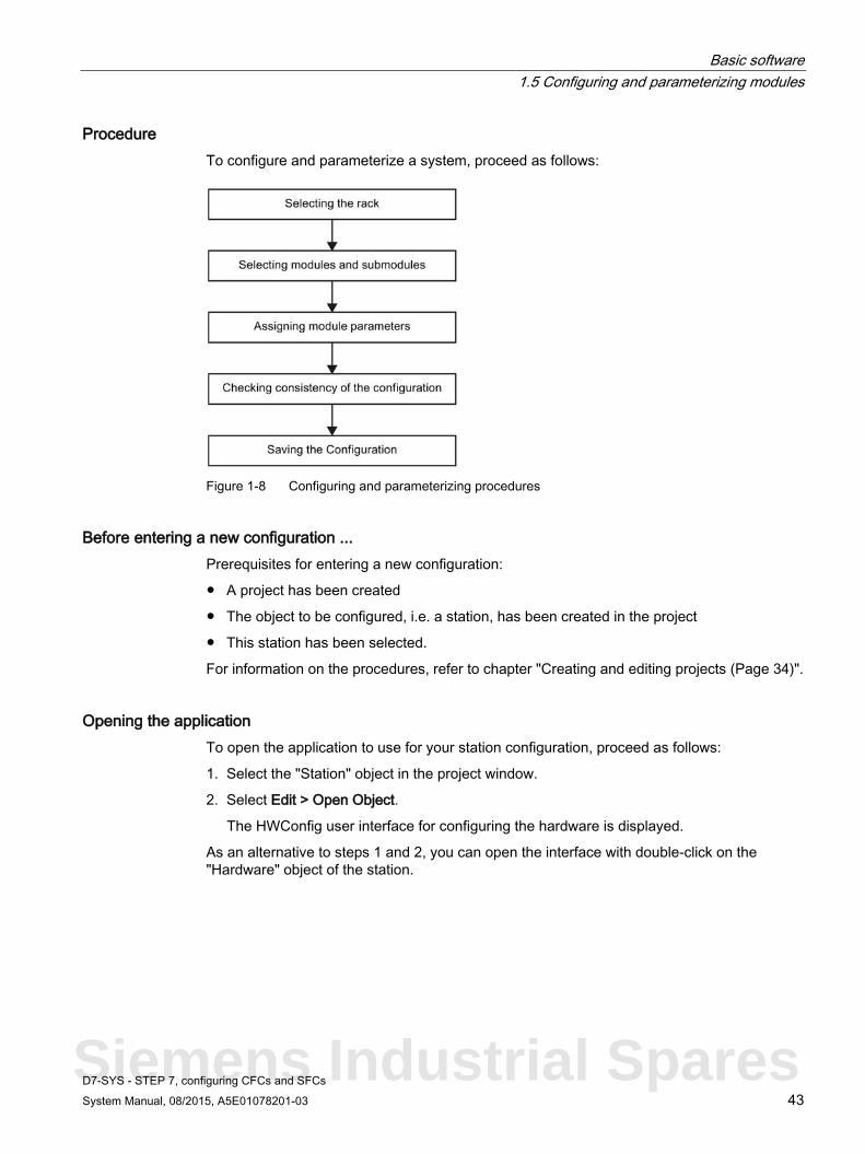
Procedure To configure and parameterize a system, proceed as follows:
Figure 1-8 Configuring and parameterizing procedures
Before entering a new configuration ... Prerequisites for entering a new configuration:
● A project has been created
● The object to be configured, i.e. a station, has been created in the project
● This station has been selected.
For information on the procedures, refer to chapter "Creating and editing projects (Page 34)".
Opening the application To open the application to use for your station configuration, proceed as follows:
1. Select the "Station" object in the project window.
2. Select Edit > Open Object.
The HWConfig user interface for configuring the hardware is displayed.
As an alternative to steps 1 and 2, you can open the interface with double-click on the "Hardware" object of the station.
Siemens Industrial Spares

Basic software 1.5 Configuring and parameterizing modules
D7-SYS - STEP 7, configuring CFCs and SFCs 44 System Manual, 08/2015, A5E01078201-03
1.5.2 Fundamental actions
Main components of the user interface Two dialog windows are provided that you can use to configure an automation system.
● Firstly, the station window in which you place the rack for the station configuration.
● Secondly, the "Hardware Catalog" window from which you can select the necessary hardware components, e. g. racks, modules and sub-modules.
● If the "Hardware Catalog" window is not displayed, select the View > Catalog menu command. You can use this command to hide or how the Hardware Catalog.
Fundamental actions Independent of the technology of a station configuration, you always need to perform the following steps:
1. To display the subfolders, expand the tree structure in the Hardware Catalog by clicking the "+" box.
2. Select a hardware component from the "Hardware Catalog" window.
3. Drag-and-drop the selected hardware component to the station window.

Basic software 1.5 Configuring and parameterizing modules
D7-SYS - STEP 7, configuring CFCs and SFCs System Manual, 08/2015, A5E01078201-03 45
This is how it is done The "Arranging racks" figure shows the fundamental actions:
Figure 1-9 Arranging racks
Summary STEP 7 supports compilation of the entire configuration by means of drag-and-drop, as usual in Windows applications. The following example shows what you must observe.
Siemens Industrial Spares

Basic software 1.5 Configuring and parameterizing modules
D7-SYS - STEP 7, configuring CFCs and SFCs 46 System Manual, 08/2015, A5E01078201-03
1.5.3 Example
Procedure Place the modules into the racks using STEP 7 exactly as you would do in your real system. Difference: In STEP 7, racks are represented by means of "configuration tables" that contain a number of rows matching the number of modules that can be inserted in the real rack.
Transposition in the configuration table The following figure demonstrates the transposition of a real configuration in the configuration table.
Figure 1-10 Transposition of the structure in the configuration table (principle)

Basic software 1.5 Configuring and parameterizing modules
D7-SYS - STEP 7, configuring CFCs and SFCs System Manual, 08/2015, A5E01078201-03 47
1.5.4 Arranging modules
Selecting and arranging racks Requirements: The station window and "Hardware Catalog" window are open. Proceed as follows:
1. Select the rack that suits your particular configuration from the "Racks" subfolder in the "Hardware Catalog" window.
2. Drag-and-drop the rack to the station window .
As an alternative to steps 1 and 2, you may double-click the rack in the "Hardware Catalog" window.
Selecting and arranging modules Proceed as follows to arrange the modules in the rack:
1. Select a module from the "Hardware Catalog" window.
2. Drag-and-drop the module to the corresponding tier of the rack.
As an alternative to steps 1 and 2, you can also select an empty tier, and then double-click the module in the "Hardware Catalog" window, or select a module and then press ENTER ↵.
1.5.5 Parameterizing modules
Parameterizing You can define the properties of a programmable module in its parameters. The specific parameters that you can set up depend on the type of module used.
Requirements The module to be parameterized must have been placed into the rack.
Parameterizing modules To parameterize modules, proceed as follows:
● Double-click on the rack tier that contains the module to be parameterized, or select the respective module and then select the Edit > Object properties menu command.
The dialog that is displayed offers one or several tabs that contain information and functions for parameterizing the module.
Siemens Industrial Spares

Basic software 1.5 Configuring and parameterizing modules
D7-SYS - STEP 7, configuring CFCs and SFCs 48 System Manual, 08/2015, A5E01078201-03
Assigning I/O addresses Assign hardware addresses to the modules as follows:
1. In the configuration table, click on a module that provides process signal I/O, e.g. a CPU, I/O, or expansion module.
2. Select the Edit > Object Properties menu command and then select the "Addresses" tab in the "Properties" dialog.
3. Enter a name for each module connector in the "Symbol" field and acknowledge with "OK". You may also assign a unique name to the symbols using the "Change default" button.
Note
The names assigned must be unambiguous throughout the station.
To open the help for an active tab, press F1 while the "Properties" dialog is open.
1.5.6 Linking hardware signals to the user program
Requirements You have assigned the I/O addresses (hardware addresses) to the modules in HWConfig.
Procedure in the CFC Link the hardware signals to the user program in the CFC as follows:
1. Configure a suitable I/O block that you can use to address the hardware signals of a connector in the CFC.
2. Select the "AD" input (hardware address) of this block, and select the Insert > Connect to address menu command. Enter the hardware address in the next dialog.
3. Select the connector name you defined in HWConfig from the "Hardware address" list box and confirm your selection with "OK".

Basic software 1.5 Configuring and parameterizing modules
D7-SYS - STEP 7, configuring CFCs and SFCs System Manual, 08/2015, A5E01078201-03 49
1.5.7 Consistency check, saving and loading
Introduction In this chapter you will learn how to perform a consistency check of your configuration and how to save it. It is presumed that the station is parameterized and configured.
Saving configurations Use the Station > Save or Station > Save and compile menu command to save, or save and compile the configuration.
If Station > Save and compile is selected, a consistency check of the configuration is included and the data is saved to the current project (as "Station" object).
If Station > Save is selected, the consistency check is omitted.
Note
The CPU charts of this station can only be compiled in the CFC if the saved hardware configuration has been checked for consistency.
Loading configurations In CFC, the hardware configuration is loaded automatically along with the compiled user program to the CPUs of the station.
Consistency check Use the Station > Check consistency menu command to run a consistency check.
● If no errors were found in the configuration, confirm the "No error" message with "OK".
● If errors were found in the configuration, a dialog opens and displays a list of errors. Press F1 to open the help for the "Check consistency" dialog.
Siemens Industrial Spares
Basic software 1.5 Configuring and parameterizing modules
D7-SYS - STEP 7, configuring CFCs and SFCs 50 System Manual, 08/2015, A5E01078201-03
1.5.8 Working in the configuration table
Introduction The following paragraph offers a few tips that facilitate your work with HWConfig.
Selecting several rows If you want to select several rows in the configuration table, for example, in order to delete several modules, or insert several modules of the same type, proceed as follows:
● Selecting all rows: – Select the Edit > Select All menu command.
● Selecting ranges: – Click in the first row of the range to be selected
– While pressing the SHIFT key, click in the last row of the range to be selected.
● Selecting several rows: – While pressing the CTRL key, click on all rows you want to select
Moving modules You can simply move modules or other components to a different valid slot in the station by means of drag-and-drop.
1.5.9 Configuring PROFIBUS DP
Introduction Communication module may be operated in master or slave mode on a PROFIBUS DP subnet.
Configuring the slave mode For information on slave mode configuration on a network containing an S7 module operating in master mode, refer to the "Configuring distributed I/O" section in the "SIMATIC Software, Basic Software for S7 and M7 STEP7" Manual. SS52-PROFIBUS is included in the "PROFIBUS DP - SIMADYN" section of the module catalog of HW Config.
Configuring the master mode FM 458-1 DP is configured for operation in PROFIBUS master mode in HW Config, as specified likewise "Configuring distributed I/O" section of the "Configuring Hardware and Communication Connections, STEP 7".
More information ... You can find additional information in the "System and Communication Configuration D7-SYS" manual.
Basic software 1.5 Configuring and parameterizing modules
D7-SYS - STEP 7, configuring CFCs and SFCs System Manual, 08/2015, A5E01078201-03 51
1.5.10 PROFINET overview
Devices in the PROFINET environment Within the context of PROFINET, "device" is the generic term for:
● Automation systems (PLC, PC, for example)
● Field devices
● Active network components (e.g. switches, routers)
● PROFIBUS or other fieldbus systems
The main characteristic of a device is its integration in PROFINET communication over Ethernet or PROFIBUS.
The following device types are distinguished based on their attachment to the bus:
● PROFINET devices
● PROFIBUS devices
PROFINET device A PROFINET device always has at least one Industrial Ethernet port. A PROFINET device can also be operated as proxy to act as representative that safeguards Ethernet communication between PROFIBUS devices (PROFIBUS slaves connected to an existing PROFIBUS interface) and additional PROFINET devices on the Ethernet.
PROFIBUS device A PROFIBUS device has at least one PROFIBUS connection to an electric interface (RS485), or to an optoelectronic interface (polymer optical fiber, POF).
A PROFIBUS device cannot take part directly in PROFINET communication, but must be implemented by means of PROFIBUS master with PROFINET link or Industrial Ethernet/PROFIBUS link (IE/PB Link) with proxy functionality.
Siemens Industrial Spares

Basic software 1.5 Configuring and parameterizing modules
D7-SYS - STEP 7, configuring CFCs and SFCs 52 System Manual, 08/2015, A5E01078201-03
PROFINET documentation The following documentation can help you with the setup and commissioning of PROFINET with SIMATIC TDC CPU555.
Title Content PROFINET system description (http://support.automation.siemens.com/WW/view/en/19292127)
Basic knowledge of PROFINET: • Network components • Data exchange and communication • PROFINET IO • Component Based Automation • Application example of PROFINET IO and Component Based Automation
Migration from PROFIBUS DP to PROFINET IO (http://support.automation.siemens.com/WW/view/en/19289930)
Guideline for migration from PROFIBUS DP to PROFINET IO.
PROFINET IO As part of PROFINET, PROFINET IO is a communication concept that is used to implement modular, distributed applications.
PROFINET IO allows you to create automation solutions, which are familiar to you from PROFIBUS.
PROFINET IO is implemented using the PROFINET standard for programmable controllers.
The STEP 7 engineering tool helps you to structure and configure an automation solution.
In STEP 7 you have the same application view, regardless of whether you are configuring PROFINET devices or PROFIBUS devices. You will program your user program in the same way for both PROFINET IO and PROFIBUS DP since you will use the extended blocks and system status lists for PROFINET IO.
For information on new and changed blocks and system status lists, refer to the programming manual Migration from PROFIBUS DP to PROFINET IO (http://support.automation.siemens.com/WW/view/en/19289930).
Additional information Information on the following topics is available on the Internet (http://support.automation.siemens.com/WW/view/en/13008499)
● Comparison of the terms used in PROFIBUS DP and PROFINET IO
● Slots and Submodules
● Integration of fieldbuses into PROFINET

Basic software 1.5 Configuring and parameterizing modules
D7-SYS - STEP 7, configuring CFCs and SFCs System Manual, 08/2015, A5E01078201-03 53
1.5.11 Configuring PROFINET
Proxy in PROFINET IO In PROFINET IO, the proxy for PROFINET IO represents each connected PROFIBUS DP slave as a PROFINET IO device on the PROFINET.
Update time
The IO controller (outputs) provides new data to all IO devices in the PROFINET IO system within the update time. This means that all the IO devices have sent their latest data to the IO controller (inputs).
Note Update times for the cyclical data exchange
STEP 7 determines the update time on the basis of the existing hardware configuration and the resulting cyclic data traffic. During this time, a PROFINET IO device has exchanged its user data with the associated IO controller.
You can set the update date either for a whole bus segment of an IO controller, or for an individual IO device.
In STEP 7, the update time can be changed manually.
The smallest possible update time in a PROFINET system depends on the following factors: • Number of PROFINET IO devices • Quantity of configured user data • Volume of PROFINET IO communication traffic (compared to the volume of PROFINET
CBA communication traffic) Additional cyclical PROFINET services
The update time dialog in STEP 7/HW Config is used to set an update date for the device to be reserved for PROFINET IO.
See the STEP 7 Online Help for more information.
Siemens Industrial Spares

Basic software 1.5 Configuring and parameterizing modules
D7-SYS - STEP 7, configuring CFCs and SFCs 54 System Manual, 08/2015, A5E01078201-03
Addressing of distributed PROFINET IO with the CPU555 From the user's point of view, receiving and sending process data via PROFINET is just like in PROFIBUS. The CTV_P and CRV_P blocks are used to send and receive, similar to PROFIBUS. However, note that you do not need to configure the @PRODP, but the @PNIO central block.
The I/O devices can be addressed in two ways:
● Addressing of the inputs and outputs operated in isochronous mode
All inputs and outputs that are operated in isochronous mode must be addressed by means of a process image (peripheral image). To do this, exactly one CRV_P (reading of inputs) or one CTV_P (writing of outputs) must be programmed.
Addressing takes place via address parameter 1. There you must specify "PIP". PIP stands for Peripheral Image Partial.
You can use address parameter 2 to rotate the bytes.
Examples of valid names:
– CTVNAM.PIP Write the data of the process image without byte rotation
– CRVNAM.PIP Read the data of the process image without byte rotation
– CTVNAM.PIP.1 Write the data of the process image with byte rotation
– CRVNAM.PIP.1 Read the data of the process image with byte rotation
Note
Optimization of the update time for the process image for isochronous I/O devices
To prevent the transfer of unnecessary data, it makes sense to place all inputs and outputs operated in isochronous mode at the beginning of the process image, starting with address 0 and trying not to leave any gaps.
Unused addresses are filled with 0.
Note Length of the data to be read or written with direct device addressing
All used addresses must be read or written with the blocks CRV_P or CTV_P.
The length of the send/receive channel must correspond to at least the highest address + 1 occupied by the modules operated in isochronous mode.
If this is not the case, the block returns a communication error. Addresses/modules in process image partition
Outputs in the process image partition cannot be written via addressing as device.
Inputs can be read both via the process image partition as well as via the device addressing.

Basic software 1.5 Configuring and parameterizing modules
D7-SYS - STEP 7, configuring CFCs and SFCs System Manual, 08/2015, A5E01078201-03 55
● Addressing of the inputs and outputs not operated in isochronous mode
All inputs and outputs that are not operated in isochronous mode must be addressed by means of the device number.
You have to program a separate CRV_P or CTV_P block for each device. The device number is then specified as address parameter 1.
You can use address parameter 2 to rotate the bytes.
Examples of valid names:
– CTVNAM.1 Write the data of device 1 without byte rotation
– CRVNAM.2 Read the data of device 2 without byte rotation
– CTVNAM.1.1 Write the data of device 1 with byte rotation
– CRVNAM.2.1 Read the data of device 2 with byte rotation
Note
Length of the data to be read or written with direct device addressing
All modules of the device must be read or written with the blocks CRV_P or CTV_P. The length must correspond exactly to the user data provided by or expected from this device. The modules are read in the order in which they are inserted into the device.
You can determine the number of user data or the structure in the hardware configuration of the respective device. Addresses/modules in process image partition
Outputs in the process image partition cannot be written via addressing as device.
Inputs can be read both via the process image partition as well as via the device addressing.
Update time / Send clock Within the update time an IO device / IO controller in the PROFINET IO system is supplied with new data by the IO controller / IO device. The update time can be configured separately for each IO device and determines the interval at which data are sent from the IO controller to the IO device (outputs) as well as data from the IO device to the IO controller (inputs).
The send clock is the period between two successive intervals for IRT or RT communication. The send clock is the shortest possible send interval for data exchange.
The calculated update times are a multiple of the send clock. The minimum possible update time thus depends on the minimum send cycle of the IO controller that can be set.
If both the IO controller and the IO device support a send clock of 250 µs, you can achieve a minimum update time of 250 µs.
It is also possible to operate IO devices that only support a send clock of 1 ms on an IO controller that works with a send clock of 250 µs. The minimum update time for the IO devices concerned, however, is then at least 1 ms.
Siemens Industrial Spares
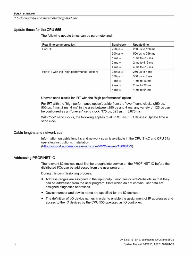
Basic software 1.5 Configuring and parameterizing modules
D7-SYS - STEP 7, configuring CFCs and SFCs 56 System Manual, 08/2015, A5E01078201-03
Update times for the CPU 555 The following update times can be parameterized: Real-time communication Send clock Update time For RT: 250 μs ⇒
500 μs ⇒ 1 ms ⇒ 2 ms ⇒ 4 ms ⇒
250 μs to 128 ms 500 μs to 256 ms 1 ms to 512 ms 2 ms to 512 ms 4 ms to 512 ms
For IRT with the "high performance" option: 250 μs ⇒ 500 μs ⇒ 1 ms ⇒ 2 ms ⇒ 4 ms ⇒
250 μs to 4 ms 500 μs to 8 ms 1 ms to 16 ms 2 ms to 32 ms 4 ms to 64 ms
Uneven send clocks for IRT with the "high performance" option
For IRT with the "high performance option", aside from the "even" send clocks (250 µs, 500 µs, 1 ms, 2 ms, 4 ms) in the area between 250 µs and 4 ms, any variety of 125 µs can be configured as an "uneven" send clock: 375 μs, 625 μs … 3.875 ms.
With "odd" send clocks, the following applies to all PROFINET IO devices: Update time = send clock.
Cable lengths and network span Information on cable lengths and network span is available in the CPU 31xC and CPU 31x operating instructions: Installation (http://support.automation.siemens.com/WW/view/en/13008499).
Addressing PROFINET IO The relevant IO devices must first be brought into service on the PROFINET IO before the distributed I/Os can be addressed from the user program.
During this commissioning process:
● Address ranges are assigned to the input/output modules or slots/subslots so that they can be addressed from the user program. Slots which do not contain user data are assigned diagnostic addresses.
● Device number and device name are specified for the IO devices.
● The definition of I/O device names in order to enable the assignment of IP addresses and access to the IO devices by the CPU 555 operated as IO controller.

Basic software 1.5 Configuring and parameterizing modules
D7-SYS - STEP 7, configuring CFCs and SFCs System Manual, 08/2015, A5E01078201-03 57
Note Name assignment for IO devices during "Device replacement without removable medium"
If the "Device replacement without removable medium" functionality is configured in HW Config, IO devices can be replaced without the user having to assign a name. To do so, the IO device has to be reset to the delivery state with "Reset to factory setting". Retrieve IP address parameters/device name in different way (PROFINET CPUs)
IP address parameters/device name via DCP: IP-address parameters / device name are assigned per DCP (Discovery and Configuration Protocol). This can happen in two ways: • with a setup tool such as PST or • STEP 7, e.g. "Edit Ethernet nodes"
Information on this is also available in the CPU 31xC and CPU 31x operating instructions: Installation (http://support.automation.siemens.com/WW/view/en/13008499).
TCP and UDP communication via the PROFINET interface With CPU555, it is possible to set up a TCP or UDP communication with CTV and CRV blocks.
To do so, the following information is required in address parameter 1:
● the first character (letter) defines the desired protocol ("T" = TCP/IP, "U" = UDP).
● The second character must be a hyphen "-".
● the next 5 digits specify the channel port number, whereby leading zeros must be specified (in this case: "01024" for port number 1024).
Note
Only the port numbers 1024 to 65535 should be used in agreement with the system administrator. Port numbers up to and including 1023 are reserved for "Well-known services" and "Unix-specific services".
Rules for address level 2:
● The first 12 digits specify the IP address of the remote coupling partner. The IP address is entered in the so-called "dot notation", but without separating dots. Leading zeros must be specified (here: "141020135198" for IP address 141.20.135.198).
● The 13th character must be a hyphen "-".
● The next 5 digits define the port number of the remote coupling partner. Leading zeros must be specified (here: "01024" for port number 1024).
Siemens Industrial Spares

Basic software 1.5 Configuring and parameterizing modules
D7-SYS - STEP 7, configuring CFCs and SFCs 58 System Manual, 08/2015, A5E01078201-03
Assignment of the IP address parameters and device name Just as every other PROFINET device, the CPU (or its PROFINET interface) also needs IP address parameters and a device name to communicate through PROFINET.
The IP address parameters consist of three parts:
● IP address
● Subnet mask
● Address of the router
The retentivity of IP address parameters and device name depends on how the assignment occurred.
The non-retentive, temporary assignment means:
● IP address parameters and device name remain valid until the next POWER OFF or CPU memory reset. After POWER OFF / POWER ON or CPU memory reset, the CPU is only accessible through the MAC address.
● Loading a temporary IP address also deletes the retentive, saved IP address parameters.
The IP address parameters and device name can be distributed in the following ways: Assignment of IP address parameters and device names Retentivity Standard method: Fixed assignment in STEP 7
IP address parameter / device assigned permanently during config-uration in STEP 7. With the loading of the configuration on the CPU, the IP-address parameter / device name are also saved in the CPU.
Data are retentive: • with POWER OFF
/ POWER ON • after CPU memory
reset • after deleting the
configuration (SDBs)
• after removing the MMC
Permanent assignment with setting "Fetch IP-address parameters / device name in a different way"
IP address parameters / device name are assigned through DCP (Discovery and Configuration Protocol). This can happen in two ways: • With a setup tool such as PST or in STEP 7 (e.g. via "Edit
Ethernet nodes"). • By the higher-level IO controller if the IM 154-8 PN/DP CPU is
operated as an I-device with prioritized startup.
Temporary assignment in STEP 7
IP address parameters / device name are assigned through DCP (Discovery and Configuration Protocol). • In case of automatic IP address assignment through "accessible
nodes" in STEP 7 if the CPU does not have an IP-address yet.
Data is not retentive:
Temporary assignment with the setting "Different method for obtaining IP-address parameters / device name"
IP address parameters / device name are assigned through DCP (Discovery and Configuration Protocol). • In case of assignment of IP address parameters / device name
through the higher-level IO controller to the I-device, if the I-device is not operated with prioritized startup.
Assignment in the user program
IP address parameter / device name are assigned in the user pro-gram through SFB 104. The retention of the IP address parameters / device name can then be determined in the corresponding param-eter dataset.
Retentivity corre-sponding with the specifications in the parameter dataset
Basic software 1.5 Configuring and parameterizing modules
D7-SYS - STEP 7, configuring CFCs and SFCs System Manual, 08/2015, A5E01078201-03 59
Retentive IP address parameters and device names can be reset as follows:
● Through "Reset to factory settings"
● Through a firmware update
Note
Temporary / fixed assignment IP-address parameters / device names • Through the temporary assignment of IP-address parameters / device names, the
retentively saved IP-address parameters / device names are reset. • With a fixed assignment of IP-address parameters / device names, previously
retentively saved parameters are replaced with the newly assigned parameters.
NOTICE
Reuse of devices
Execute the "Reset to factory settings" before you install a device with retentive IP address parameters / device names in different subnetworks / systems or before you place it in storage.
Information on IP address assignment for the I-device is available in the System Manual PROFINET system description (http://support.automation.siemens.com/WW/view/en/19292127).
Additional information Additional information on PROFINET is available in the following documents:
● System Manual Industrial Ethernet / PROFINET Passive Network Components (http://support.automation.siemens.com/WW/view/en/84922825)
● System Manual Industrial Ethernet Industrial Ethernet / PROFINET Industrial Ethernet (http://support.automation.siemens.com/WW/view/en/27069465).
● System Manual PROFINET system description (http://support.automation.siemens.com/WW/view/en/19292127)
● Catalog Industrial Communication IK PI
Siemens Industrial Spares

Basic software 1.5 Configuring and parameterizing modules
D7-SYS - STEP 7, configuring CFCs and SFCs 60 System Manual, 08/2015, A5E01078201-03
1.5.12 Configuring the PROFINET IO system
How to configure the PROFINET IO-system
Configuring hardware in STEP 7 SIMATIC Manager
1. Double-click the following "STEP 7" icon
2. Select File > New.
3. Enter "My First Project" in the Project dialog box.
4. Select the storage location (path) "Drive:\Siemens\Step7\S7proj".
5. Click OK.
Result: Your new project is displayed.
6. Highlight the project and select "Insert new object" > Station > SIMATIC TDC station.
Result: The hardware object "SIMATIC TDC-Station" is inserted.
7. Select the "SIMATIC TDC station" hardware object and then select Edit > Open object.
Result: HW Config opens.
8. Select the rack UR6021.
9. Place the CPU module CPU555 in slot 1.
Result: The properties dialog of the PN-IO interface opens.
10. Click "New" on the "Properties – Ethernet Interface PN-IO" dialog box to create a new subnet.
Result: The "Properties – New Industrial Ethernet Subnet" dialog box opens.
11. Assign a name and confirm with "OK."
Result: You are back to the "Properties – Ethernet Interface PN-IO" dialog box.
12. Enter the IP address and the subnet mask in the dialog box and confirm with "OK".
This information is available from your network administrator.
Note: The worldwide unique MAC address is preset by the manufacturer and cannot be changed.
13. If you set up a connection via router, you must select the "Use router" option button and also enter the address of the router.
This information is also available from your network administrator.
14. Click "OK" to close the properties dialog box.
15. Insert the IO devices in the PROFINET IO system and configure them. You can find more information in the product documentation of the IO devices used.
16. Select Edit > Object properties to assign device names and device numbers to the IO devices.

Basic software 1.5 Configuring and parameterizing modules
D7-SYS - STEP 7, configuring CFCs and SFCs System Manual, 08/2015, A5E01078201-03 61
17. If the diagnostic events should lead to the PROFINET interface activating a diagnostic interrupt OB (OB 82), select the check box "OB 82 / Fault task - Call at communications interrupt" in the properties of the PROFINET IO controller of the CPU555 in the "PROFINET" tab.
Tip: This information on the events is also available in the diagnostics buffer of the CPU.
18. Save your configuration with Station > Save and compile.
19. Download the configuration to the CPU.
To do so, you have the following options:
– Online via the PROFINET interface (see Online download (Page 71)):
To download the configuration, select the IP address of the CPU. You can display the "accessible nodes" via "PLC" (if the CPU does not have an IP address yet, select the MAC address of the target CPU). In the next dialog box, you can assign the configured IP address to the CPU.
The programming device must be connected to the subnet. The PG interface must be set to TCP/IP. Setting in the IE-PG Access tab of the interface properties dialog box: Assign Project-Specific IP-Address (Options > Set PG/PC interface > "Access path" tab > TCP/IP (Auto) > Properties... > IE-PG access > Assign project-specific IP address).
– Offline (see Offline loading (Page 73)) by saving the data to a Micro Memory Card in SIMATIC Manager on your programming device, and then inserting the Micro Memory Card into the CPU
20. Assign names to the IO devices.
Requirement: The programming device must be connected to the subnet. The PG interface must be set to TCP/IP (Auto) mode. Setting in the IE-PG Access tab of the interface properties dialog box: Assign Project-Specific IP Address.
Procedure: Select the various IO devices in HW Config, then select PLC > Ethernet > Assign Device Name to assign the corresponding device names to them.
Note
When you have configured "Device replacement without removable medium" and specified the set topology of the PROFINET IO system with the topology editor, you may not have to assign the device name. For this to be the case, the actual topology must correspond with the set topology and the devices must be reset to the factory settings.
Note
The CPU can only assign the IP address automatically, and thus enable its correct communication with the IO device, after you have assigned a device name to the latter.
If the configuration of the IO devices you downloaded to the CPU corresponds with their physical configuration on the subnet, the CPU addresses the IO devices.
Siemens Industrial Spares

Basic software 1.5 Configuring and parameterizing modules
D7-SYS - STEP 7, configuring CFCs and SFCs 62 System Manual, 08/2015, A5E01078201-03
Result
You used STEP 7 to configure the PROFINET interface of your CPU and the PROFINET IO system. The CPU can now be reached by other nodes in your Industrial Ethernet subnet.
Additional information Detailed information about address assignment of the PROFINET IO interface and on the configuration of its properties and ports is available in the Online Help of STEP 7 and in the PROFINET system description (http://support.automation.siemens.com/WW/view/en/19292127).

Basic software 1.5 Configuring and parameterizing modules
D7-SYS - STEP 7, configuring CFCs and SFCs System Manual, 08/2015, A5E01078201-03 63
1.5.13 Use of isochronous I/O
Note Isochronous mode with CPU555
Because the signal "PNIO cycle (receive data ready)" has a high jitter, it is not suitable as basic clock cycle (T0). For this reason, the PNIO send clock is used as basic clock cycle. However, this means that the receive data was not yet read at the start of T1 and must be read in with a delay.
To achieve this, the basic clock cycle must be delayed in HW Config or in the user program.
The EVA model should be observed when using isochronous I/O. The EVA model is a program processing model:
● Input: Read in process image partition with CRV or CRV_P
● Processing: In the user program
● Output: Output process image partition with CTV or CTV_P
A task needs to be performed in isochronous mode and the calls of the CTV_P and CRV_P blocks need to be executed with address stage 1 "PIP" in this task.
To do this, either an interrupt task must be started with "PNIO cycle (receive data ready)" or T0 must be synchronized to "PNIO cycle (send cycle)". In this case, the inputs are read and made available to the user program.
For the synchronization of T0 to "PNIO cycle (send cycle)", please also set a suitable delay time so that the receive data is available when T0 is started. If the selected delay time is too small, you will receive an error message at the CRV_P block informing you that the receive data is not yet available.
Siemens Industrial Spares

Basic software 1.5 Configuring and parameterizing modules
D7-SYS - STEP 7, configuring CFCs and SFCs 64 System Manual, 08/2015, A5E01078201-03
You can derive a guideline value for the delay time to be selected with the following formula:
Delay time = 300 µs + size of process image partition in bytes x 1 µs
Figure 1-11 Synchronize CPU to the PROFINET clock cycle

Basic software 1.5 Configuring and parameterizing modules
D7-SYS - STEP 7, configuring CFCs and SFCs System Manual, 08/2015, A5E01078201-03 65
Also select the IO system number and the process image partition in the Isochronous mode tab.
Figure 1-12 Setting the isochronous mode
Siemens Industrial Spares

Basic software 1.6 Creating communication connections
D7-SYS - STEP 7, configuring CFCs and SFCs 66 System Manual, 08/2015, A5E01078201-03
1.6 Creating communication connections
Overview If it is necessary for your automation solution to implement several CPUs, or integrate the display units, then you must ensure that the components concerned are able to communicate.
You can basically distinguish between two communication types:
1. Internal communication of a station
2. Communication with display devices
Note
Communication links between the CPUs are always created in CFC.
1.6.1 Internal communication of a station
Overview You have two options of enabling data exchange between the CPUs:
Table 1- 1 Internal communication of a station
Communication by means of Properties $ signals: • adequate for many applications
• Simple to configure.
Virtual connections: • For more complex communication relations between transmitters and receivers
• More engineering effort.

Basic software 1.6 Creating communication connections
D7-SYS - STEP 7, configuring CFCs and SFCs System Manual, 08/2015, A5E01078201-03 67
1.6.1.1 Communications by means of $ signals
Purpose of the $ signals $ signals facilitate efficient communication between a sender and several receivers.
Requirements of communication by means of $ signals Requirements of communication by means of $ signals:
● The sender and receivers operate on different CPUs in the same station.
● A buffer memory module for communication between the CPUs is inserted in the rack and is initialized.
There are two types of $ signals:
Table 1- 2 $ signal types
Type Properties Standard Maintains data consistency Fast Data transfer with minimum deadtimes
Procedure 1. In SIMATIC Manager, double-click on the CFCs that contain the I/Os for the
communication connection.
2. In the CFC application window, select the block output from which the $ signal is originate.
3. Select the Insert > Connection to address menu command.
4. Select the "Bus" and "Type" options.
5. Enter a unique name with maximum a length of 14 characters in the "Name" field. Confirm your entries with "OK".
6. Select the block input for the $ signal.
7. Select the Insert > Connection to address menu command.
8. In the "Name" field, enter the $ signal name that is assigned to the block output. Confirm your entries with "OK".
Note
• You may route the $ signal to additional block inputs. Proceed as specified in steps 6, 7, and 8.
• In step 8, you will be offered a "Name" list box that contains a selection of configured $ signals.
• For more information, press F1 while the "Shared address" dialog is open.
Siemens Industrial Spares
Basic software 1.6 Creating communication connections
D7-SYS - STEP 7, configuring CFCs and SFCs 68 System Manual, 08/2015, A5E01078201-03
1.6.1.2 Communication via virtual connections
Requirements You need to configure additional function blocks, e.g.:
● Transmit and receive blocks of the process data service
● Central blocks for managing the links used.
Communication relations Virtual connections enable communication relations between:
● 1 transmitter - 1 receiver
● 1 transmitter - several receivers
● Several transmitters - 1 receiver
Specify the appropriate data transmission mode at the transmit and receive blocks.
The transmitters and receivers may be operated on different CPUs and be interconnected by means of user-defined links.
Procedure 1. In SIMATIC Manager, double-click on the CFCs that contain the I/Os for the
communication connection.
2. In the CFC application window, select the block output from which the virtual connection originates.
3. Select the Insert > Connection to address menu command.
4. Select the "Virtual connection" check box.
5. Enter a unique name in the "virtual connection name" field and a number in the "sequence number field". The "virtual connection name" may consist of up to six characters. Confirm your entries with "OK".
6. Select the block input for the virtual connection.
7. Select the Insert > Connection to address menu command and the "Virtual connection" check box.

Basic software 1.6 Creating communication connections
D7-SYS - STEP 7, configuring CFCs and SFCs System Manual, 08/2015, A5E01078201-03 69
8. In the "Virtual connection name" field, enter the name assigned to the block output, and the number assigned to the block output in the "Sequence number" field. Confirm your entries with "OK".
9. Configure the necessary transmit, receive, and central blocks. For information on the necessary steps, refer to the "System- and communication configuring D7-SYS" Manual.
Note
• You may route the virtual connection to additional block inputs. Proceed as specified in steps 6, 7, and 8.
• In step 8, you are offered a selection of configured virtual connection names in the "Virtual connection name" list box.
• For more information, press F1 while the "Shared address" dialog is open.
For additional information on virtual connections refer to the system manual "System and communication configuration D7-SYS (http://support.automation.siemens.com/WW/view/de/8776461/0/en)".
1.6.2 Communication with display devices For information on communication with display devices refer to the system manual "System and communication configuration D7-SYS (http://support.automation.siemens.com/WW/view/de/8776461/0/en)".
Siemens Industrial Spares

Basic software 1.7 Loading programs
D7-SYS - STEP 7, configuring CFCs and SFCs 70 System Manual, 08/2015, A5E01078201-03
1.7 Loading programs
1.7.1 Overview
Overview After having completed your configuration, parameterization and the program, transfer the user program to the target system. This section describes how to select the interface and load user programs.
The entire user program of a CPU is loaded to the automation system in a single pass. The hardware configuration of this CPU as well as the operating system are loaded automatically.
Options for downloading data to the CPU
Table 1- 3 Options for downloading data to the CPU
Download via online connection (access to the target system):
The user program is downloaded to the memory module inserted in a submodule slot of the CPU. The program is retained on power failure.
Loading the user program to the memory module in offline mode:
Loading via PCMCIA socket The user program is loaded to a memory module in a PCMCIA slot of the programming device. The memory module containing the loaded user pro-gram is inserted into the submodule slot of the CPU. Loading via prommer (MMC for CPU555) The prommer is connected to the programming device via USB. The user program is loaded from the programming device to the memory module in the prommer. Then the memory module contain-ing the loaded user program is inserted into the submodule slot of the CPU. Loading via OmniDrive The OmniDrive is connected to the programming device via USB. The user program is loaded from the programming device to the memory module in the OmniDrive. Then the memory module con-taining the loaded user program is inserted into the submodule slot of the CPU.
Note
It is necessary to restart the station containing this CPU in order to activate the user program that you loaded to the CPU's memory module.

Basic software 1.7 Loading programs
D7-SYS - STEP 7, configuring CFCs and SFCs System Manual, 08/2015, A5E01078201-03 71
1.7.2 Online download
1.7.2.1 Selecting the interface for the online connection You need an online connection between the engineering and target systems to carry out the following tasks:
● Online download to a CPU
● Testing user programs
● Displaying the module status of a CPU
● Displaying and changing the operating state of a CPU
You can select the online interface that is to be used to set up an online connection to the target system.
Interfaces for online connections Available interfaces for online connections:
● Multi-point interface (MPI)
● RS232 interface (COM1 or COM2 / not for CPU555)
● Ethernet interface
Selecting the interface for online connections 1. Select Start > Simatic > STEP 7 > Set PG-PC interface from the Windows task bar.
2. Select the interface used and set the correct parameters.
Note
• You can press F1 while the dialog is open to obtain additional help. • The programming device must be equipped with an MPI interface for online
connections. • Verify the correct settings of the properties of the selected interface. The MPI baud
rate must agree with the setting at the coupling partner.
Siemens Industrial Spares

Basic software 1.7 Loading programs
D7-SYS - STEP 7, configuring CFCs and SFCs 72 System Manual, 08/2015, A5E01078201-03
1.7.2.2 Online download to a CPU
Requirements ● You have set up an online connection between the programming device and the station
containing the CPU.
● You have compiled the user program of the CPU in the CFC.
Additional requirements for loading a T400 CPU ● Switch S1/8 on the T400 is turned off
● The online connection between the programming device and T400 is up (serial interface X01, terminals 67 and 68).
Procedure 1. In the CFC, display the window of any chart from the CPU to be loaded in the foreground.
2. Select Target system > Download in the CFC.
3. From the load method area, select the "online" check box, and confirm this with "Download".
4. Repeat steps 1 to 3 for other CPUs of the station.
5. Select Target system > Operating state in the CFC.
6. Restart the station in order to run the loaded user program.

Basic software 1.7 Loading programs
D7-SYS - STEP 7, configuring CFCs and SFCs System Manual, 08/2015, A5E01078201-03 73
1.7.3 Offline loading
1.7.3.1 Useful information about memory modules and the programming interface
NOTICE
Note the following: • Safe and reliable operation cannot be guaranteed unless you use the memory modules
that Siemens has approved for operation with SIMATIC TDC. SIMATIC S7/M7 Memory Cards cannot be used.
• Do not attempt to load a memory module that is registered as drive in Windows, as you will risk the loss of files stored on this drive.
Approved memory modules PCMCIA/JEIDA modules to PC Card Standard are used as memory module for the CPUs.
MC memory modules are used as memory modules for the CPU550 and CPU551.
The SIMATIC Micro Memory Cards can be used as a memory cards for the FM 458-1 DP and SIMATIC TDC CPU555 (see Catalog ST DA or Interactive Catalog CA 01 (https://eb.automation.siemens.com/goos/WelcomePage.aspx?regionUrl=%2fww&language=en)).
The memory modules approved by Siemens are listed along with their order numbers in the "Submodules - program memory" section of the module catalog of HW Config.
Note FLASH memory modules series 1
Older FLASH memory modules ("Series 1") cannot be used.
Programming interface A PCMCIA slot to PC Card Standard is used as programming interface on the programming device. Notebooks and the currently available Siemens programming devices are usually equipped with an integrated PCMCIA slot. Corresponding expansion boards are available for Desktop and Tower stations.
A number of manufacturers provide products that integrate a PCMCIA memory module as drive in Windows (e.g. "Flash File System", "Flash Translation Layer", ...).
Usually, trouble-free interaction of STEP 7 software with these products can be ensured. However, Siemens cannot assume warranty in this context due to the multitude of products offered.
Particular caution should be exercised when using products developed for Windows 3.1/3.11.
Siemens Industrial Spares

Basic software 1.7 Loading programs
D7-SYS - STEP 7, configuring CFCs and SFCs 74 System Manual, 08/2015, A5E01078201-03
1.7.3.2 Selecting the load interface
Requirements You have activated PC card support on your programming device:
● A "PC card (PCMCIA)" icon is displayed in the Windows "Control Panel".
Note
If PC Card support is not enabled, follow the instructions under the "PC Cards, activating support of" index entry in the Windows Online Help.
Selecting the programming interface 1. Select the following menu command from the Windows task bar
– Windows XP: Start > Simatic > STEP 7 > Select D7-SYS-PCMCIA Interface.
– Windows 7: Start > Siemens Automation > SIMATIC > STEP 7 > Select D7-SYS-PCMCIA Interface.
2. In the "PCMCIA slot" dialog, select the PCMCIA slot and confirm your selection with "OK".
Note
• If your programming device has several PCMCIA slots, select the one to be used for offline loading. Slot 1 is automatically selected.
• You can press F1 while the "PCMCIA slot" dialog is open to get additional help.

Basic software 1.7 Loading programs
D7-SYS - STEP 7, configuring CFCs and SFCs System Manual, 08/2015, A5E01078201-03 75
1.7.3.3 Loading data to a memory module in offline mode
Requirements ● Your programming device is equipped with a PCMCIA slot.
● PC Card support is enabled.
● You have selected the PCMCIA slot to be used for loading the data.
● You have compiled the user program of the CPU in the CFC.
Procedure 1. In the CFC, display the window of any chart from the CPU to be loaded in the foreground.
2. Insert a suitable memory module into the selected PCMCIA slot of the programming device. Ensure that the write protection of the memory module is not set.
3. Select Target system > Download in the CFC.
4. In the load method area, select the "offline" option and confirm your selection with "Download".
5. Repeat steps 1 to 4 for other CPUs of the station.
6. Switch off power to the station, insert the memory module into the appropriate submodule slots of the CPUs and then power-up the station.
Note
Make sure that you insert the memory module into the correct "CPU".
Siemens Industrial Spares

Basic software 1.8 Testing programs
D7-SYS - STEP 7, configuring CFCs and SFCs 76 System Manual, 08/2015, A5E01078201-03
1.8 Testing programs
Overview A program is tested using the CFC in test mode. This solution offers you the option of editing the configuration in online mode and, in many cases, saves you from having to reload the CPU.
While the CFC is in test mode and your station is online, you can:
● Display the values of any block I/O
● Change values at block inputs that are not interconnected
● Delete interconnections between blocks
● Insert interconnections between blocks
● Delete function blocks
● Insert new function blocks (provided that the block type is already available on the CPU)
● Change the number of inputs of generic blocks
1.8.1 Testing programs
CAUTION
Note: • Be aware of the risks involved with runtime tests on the system, i.e. incorrect actions,
functional faults, or program errors may cause severe injury or damage to assets! • Before running this test function, you must be absolutely certain that hazardous states
are safely excluded!
Note • Changes are made simultaneously in the charts on the programming device and in the
runtime user program. The status of the user program is identical in the engineering and target systems.
• Changes will be retained after a station restart or power off.
Requirements ● You have set up an online connection between the programming device and the stations
containing the CPUs to be tested.
● The user program to be tested is loaded on the CPUs to test.
● The CPUs are in RUN, or in STOP operating state (monitor only).

Basic software 1.8 Testing programs
D7-SYS - STEP 7, configuring CFCs and SFCs System Manual, 08/2015, A5E01078201-03 77
Additional requirements for testing user programs on a T400 CPU ● Switch S1/8 on the T400 is turned off
● The online connection between the programming device and T400 is up (serial interface X01, terminals 67 and 68).
Procedure 1. Open the charts to be tested in the CFC.
2. Select Test > Test mode
3. Select the target system I/O that you want to monitor as follows:
– Select an I/O of a function block and select menu command Debug > Register I/O.
– Select one or several function blocks and then select menu command Test > Register I/O. All I/Os of the selected function blocks are now registered for testing
4. and the actual values will be displayed.
Note
The following functions of the CFC edit mode result in corresponding online changes in test mode: • Editing parameter values • Deletion and insertion of interconnections • Deletion and creation of blocks • Changing the input number of generic blocks
For more information, refer to chapter "CFC" in the "STEP 7 Option packages for D7-SYS" Manual, or to the CFC Online help to CFC.
Siemens Industrial Spares

Basic software 1.9 Diagnostics
D7-SYS - STEP 7, configuring CFCs and SFCs 78 System Manual, 08/2015, A5E01078201-03
1.9 Diagnostics
Overview The term diagnostics denotes the detection, evaluation, and reporting of diagnostics events that occur in the control system. Each CPU contains an integrated diagnostics buffer that is used to enter detailed information on all diagnostics events.
In a diagnostics session, you evaluate the following information that is stored on the CPU:
● Module status information
● CPU operating state information
Interpretation of this information facilitates the identification, localization, and elimination of errors and reduces downtimes that result from faults or errors.
Diagnostics options You have the following diagnostics options:
● Call of the module status from the offline project view in SIMATIC Manager
● Call of the module status from the CFC
● Value at connection YTS for communication blocks
● Display of the type of diagnostics event on the front panel 7-segment display of the respective CPU module
For more information
● on the status display of the CPU modules, refer to the "Hardware" Manual.
● on the value at connection YTS of communication modules, refer to the "Function Block Library" Reference Manual, or to the error numbers listed in "Help on events" in the Online Help. (Press F1 while the CFC is open and call the "Help on events" topic under "CFC”.)
Figure 1-13 Calling diagnostics from SIMATIC Manager
You do not have to configure the diagnostics data acquisition by diagnostics function, as it is available by default and running automatically.

Basic software 1.9 Diagnostics
D7-SYS - STEP 7, configuring CFCs and SFCs System Manual, 08/2015, A5E01078201-03 79
Diagnostics events Operating mode transitions (e.g. RUN to STOP) and entries of the following error classes are displayed as diagnostics event:
● Initialization error ("0")
● Monitoring error ("b")
● Communication error ("C")
● Task Manager error ("E")
● User error ("A") (diagnostics event that you define in function block USF)
Siemens Industrial Spares

Basic software 1.9 Diagnostics
D7-SYS - STEP 7, configuring CFCs and SFCs 80 System Manual, 08/2015, A5E01078201-03
1.9.1 Diagnostics in the offline project view in SIMATIC Manager
Note • The station's configuration data (HWConfig and CFC) must be available for diagnostics
on the PC/programming device. • If the station's configuration data is not available on your PC/programming device, you
must configure the station hardware in HWConfig. In this case, the scope of diagnostics will be restricted, as you cannot have access charts.
1.9.1.1 Transferring diagnostics information The CPU identifies the error and writes the diagnostic events to the diagnostics buffer. These diagnostics messages can be read on the PC/programming device.
Figure 1-14 Transferring diagnostics information
Reading diagnostics information You can view the diagnostics messages in plain text using the following tabs in SIMATIC Manager:
● "Module status" tab
– indicates where and when the error occurred
● "Diagnostics" tab
– indicates the type of diagnostics event associated with the entry (user error, communication error, operating mode transitions, etc.)
– displays the module name of the diagnostics event (if available)

Basic software 1.9 Diagnostics
D7-SYS - STEP 7, configuring CFCs and SFCs System Manual, 08/2015, A5E01078201-03 81
1.9.1.2 Procedure for requesting the module status in SIMATIC Manager
Requirements ● You have set up an online connection between the programming device and the stations
that contain the CPUs of which you want to request the status.
● The CPUs are in RUN, or in STOP operating state.
Procedure 1. Select a station from the project view (offline) in SIMATIC Manager and open it with
double-click.
2. Select the CPU to be diagnosed.
3. Select PLC > Module status.
4. The "Module status" dialog opens and displays the "General" and "Diagnostics buffer" tabs of the CPU.
5. Click "Special diagnostics" to open the "Diagnostics" dialog that contains the "Diagnostics buffer" tab.
Note
You can press F1 while the "Module Information" or "Diagnostics" tab is open to obtain further help.
1.9.1.3 Evaluating the diagnostics buffer
Organization of the diagnostics buffer The diagnostics buffer is designed as FIFO buffer with a maximum capacity of 120 entries. Once the maximum number of entries has been reached, the oldest entry will be overwritten on each new diagnostics buffer event and the entries are shifted accordingly. This means that the most recent diagnostics entry is always in the first position.
Note • The content of the diagnostics buffer is retained if you RESET the station. • The entries in the diagnostics buffer will be cleared on power failure, or if you switch off
the power supply to the rack while the backup battery is missing or low.
Siemens Industrial Spares

Basic software 1.9 Diagnostics
D7-SYS - STEP 7, configuring CFCs and SFCs 82 System Manual, 08/2015, A5E01078201-03
Special diagnostics - "Diagnostics buffer" tab Events
The following information must be entered for each diagnostics event in the list of the "Diagnostics buffer" tab in the " Diagnostics" dialog:
● Consecutive number
● Time
● Date
● Error class
● Event (short description)
● Block name (number of the CPU and name of the chart and block name at which the diagnostics event occurred, separated by a period).
Event details
Full description for the selected event in the list:
● Event name and number
● Additional information, dependent on the event
● Incoming or outgoing event
Help on Event
Use the "Help on event" button to get information on the cause of the event selected in the list field and on corresponding troubleshooting routines.
Special diagnostics - "Memory" tab (CPU555 only) In addition to the memory page that displays S7 information directly in the program, the use of the memory areas SAVE and TSAVE is displayed here (SAVE/TSAVE: battery-buffered memory areas of the TDC CPU).
The allocation of the two memory areas is shown both graphically and in absolute values.
Special diagnostics - "Load" tab (CPU555 only) This shows the load of each task and the utilization of the processor. The 5 tasks are displayed automatically. To display the load on the processor, the PSL block must be configured.
The load of the 5 tasks and the utilization of the processor (if configured) is displayed both graphically and in absolute values here.

Basic software 1.9 Diagnostics
D7-SYS - STEP 7, configuring CFCs and SFCs System Manual, 08/2015, A5E01078201-03 83
1.9.2 Diagnostics in the CFC In the CFC, you can request the module status of a CPU.
The module status information includes the following:
● Error fields of the CPU
● The exception buffer of the CPU
1.9.2.1 Procedures for requesting the module status from the CFC
Requirements ● You have set up an online connection between the programming device and the stations
that contain the CPUs of which you want to request the status.
● The CPUs are in RUN, or in STOP operating state.
Procedure 1. Move the window of any chart of the CPU of which the module status is to be requested
to the foreground in the CFC.
2. Select Target system > Module status.
3. Select the "Error fields" or "Exceptions" tab.
Note
You can press F1 while the "Module status" dialog is open to get further help.
For more information on the content of the exception buffer, contact the Hotline.
Siemens Industrial Spares

Basic software 1.9 Diagnostics
D7-SYS - STEP 7, configuring CFCs and SFCs 84 System Manual, 08/2015, A5E01078201-03
1.9.2.2 Displaying and changing the operating state
Requirements ● You have set up an online connection between the programming device and the stations
containing the CPUs of which you want to request the operating state.
● The CPUs are in RUN, or in STOP operating state.
Procedure 1. Move the window of any chart of the CPU of which the module status is to be requested
to the foreground in the CFC.
2. Select Target system > Operating mode. The "Operating state" dialog displays the current operating state of the CPU.
3. Select "Restart" if you want to restart the CPUs of the station.
4. Select "Stop" if you want to set the CPUs of the station to the "User stop" status.
Note
You can press F1 while the "Operating state" dialog is open to get further help.

Basic software 1.10 Archiving user programs
D7-SYS - STEP 7, configuring CFCs and SFCs System Manual, 08/2015, A5E01078201-03 85
1.10 Archiving user programs
Overview Individual projects can be saved to an archive file in compressed format. These compressed files can be saved to hard disk, or to portable data carriers (floppy disks).
1.10.1 Archiving programs
Application Use SIMATIC Manager to archive user programs.
The archiving function provides an interface that you can use to open your preferred archiving program.
Approved archiving programs You may use the following archiving programs:
● pkzip V2.04g or higher
● arj V2.41a or higher
● lha V2.13 or higher
● winzip V6.0 or higher
The arj archiving program is included in your software package.
Requirements The archiving program is installed on your system. For information on the implementation of the program in STEP 7, refer to chapter "Archiving projects (Page 86)".
Note
A DOS window is displayed while archiving/retrieving the data. You cannot continue to work in SIMATIC Manager until this window is closed again.
Setting the properties of the archiving program In the properties dialog of the archiving program, specify to close the DOS window automatically on completion of the archiving/retrieval process.
Proceed as follows:
1. Select the archiving program and select File > Properties in Windows Explorer.
2. Select the "Program" tab in the next dialog.
3. Select the "Close when completed" check box.
4. Click "OK".
Siemens Industrial Spares

Basic software 1.10 Archiving user programs
D7-SYS - STEP 7, configuring CFCs and SFCs 86 System Manual, 08/2015, A5E01078201-03
1.10.2 Archiving projects
Configuring your preferred archiving program Proceeds as follows to set up an archiving program:
1. Select Options > Customize in SIMATIC Manager A tab dialog is displayed.
2. Select your preferred archiving program on the "Archiving" tab.
The arj archiving program is set by default.
Setting the search path for the archiving program The standard STEP 7 configuration assumes that the archiving program is installed in the DOS search path. If the archiving program is installed outside the search path, proceed as follows:
1. Select Options > Customize in SIMATIC Manager A tab dialog is displayed.
2. Open the "Configure archiving" dialog with click on the "Configuring" button in the "Archiving" tab.
3. Enter the path name of the archiving program in the "Program path" field, or select it using the "Search" button.
4. Close the dialogs with "OK".
Setting default target directories You are provided the possibility of setting default target directories for archiving and retrieving. Using these settings, you can save yourself from having to enter these directories when archiving and retrieving.
Proceed as follows to set default target directories:
1. Select Options > Customize in SIMATIC Manager
2. Select the "Archiving" tab from the next dialog.
3. Activate the "Use the archive directory when archiving" or the "Use the archive directory when retrieving" option.
4. Enter the path in the corresponding text box, or click on the "Search" button to select a directory.
For retrieving, you can select the Autoscan function for the target directory.
5. Close the dialog with "OK".

Basic software 1.10 Archiving user programs
D7-SYS - STEP 7, configuring CFCs and SFCs System Manual, 08/2015, A5E01078201-03 87
Archiving projects Proceed as follows to create an archive
1. Ensure that no windows are open for the project that you want to archive.
2. Select the File > Archive > Project menu command.
3. A further dialog is displayed, depending on your archiving settings (see Options > Customize, "Archive" tab). In this dialog, you can set the target directory for the archive file, the file names, and the file type. STEP 7 determines the archiving program to be used based on the file type (e.g. "zip" for PKZIP).
4. Select the project to archive from the next dialog.
5. A further dialog provides you with options for making special settings (e.g. to span the archive to multiple floppy disks). The dialog box is only displayed if you activated the options prompt in your archiving settings, and if the archiving program supports options.
A DOS window opens to run the archiving process. The project data will be compressed and archived to the target directory.
Copying to floppy disk You can archive a project as mentioned above and copy the archive file to a floppy disk. It is also possible to select a floppy disk drive straight away in the "Archiving" dialog.
Siemens Industrial Spares

Basic software 1.10 Archiving user programs
D7-SYS - STEP 7, configuring CFCs and SFCs 88 System Manual, 08/2015, A5E01078201-03
1.10.3 Retrieving projects
Overview You cannot edit project archives directly. This data must first be retrieved from the archive.
Editing archived projects Proceed as follows:
1. In SIMATIC Manager, select the File > Retrieve menu command.
2. Select the archive file that contains the compressed project in the next dialog.
Whether or not additional dialogs will be displayed, depends on the settings you made in the "Archive" tab that you can open with Options > Customize.
3. In the next dialog, if applicable, select the target directory to which the data is to be retrieved.
4. An additional will possible open for you to make further settings for the retrieval.
Note
The directory names contained in the path may not exceed a length of eight characters
After the dialog has been closed, a DOS window is opened for running the retrieval.
1.10.4 Opening retrieved projects During retrieval, the project will be created and its contents are fetched from the archive. You may now open and edit the project, or copy and paste particular parts to a different project.
The projects are not included in the selection when you initially open the corresponding dialog.
In this case, proceed as follows:
1. Click "Browse".
2. Select the project in the dialog. The project is available under its filename project name.s7p.

Basic software 1.11 Printing
D7-SYS - STEP 7, configuring CFCs and SFCs System Manual, 08/2015, A5E01078201-03 89
1.11 Printing
Overview Once you have completed generating the program for your automation task, you can print all essential data using the integrated print function of STEP 7 in order to create a project documentation.
Optional DOCPRO package You can use the optional DOCPRO package to create, edit and print standardized circuit manuals and therefore obtain a plant documentation that is compliant with DIN and ANSI standards.
1.11.1 Printer setup
Printer setup Select the File > Print Setup menu command to set up a printer and to define the page orientation (portrait or landscape).
Setting the page format Select the File > Page Setup menu command to set the page format for printing (e.g. A4, A5, Letter).
Setting up headers and footers Adapt the paper format to suit the print form. If the form is too wide, the right margin is printed on a successive sheet.
To configure the headers and footers for your printed documents, select the File > Headers, footers menu command in SIMATIC Manager
Print preview You can open a preview of the print form using the File > Preview menu command.
Note
Certain STEP 7 applications provide only a restricted scope of these menu commands.
Siemens Industrial Spares

Basic software 1.11 Printing
D7-SYS - STEP 7, configuring CFCs and SFCs 90 System Manual, 08/2015, A5E01078201-03
1.11.2 Print start
Project components that you can print The following specific components of a project can be output to a printer:
● The configuration table of a station, including the layout of the modules and module parameters
● CFC charts
Basic procedure To print the project files, proceed as follows:
1. Open the relevant object to view the information to be printed on-screen.
2. Open the "Print" dialog using the File > Print... command in the corresponding window.
Depending on the window, the menu bar root may contain the "Station" instead of the "File" entry.
3. You can customize the print (e.g. printer, print range, number of copies) in the dialog and then close it. For more detailed information on printing, refer to the Online Help.

D7-SYS - STEP 7, configuring CFCs and SFCs System Manual, 08/2015, A5E01078201-03 91
CFC 2 2.1 Working with the CFC editor
This Chapter provides system-specific information on the CFC (Continuous Function Chart), shows how it is embedded in the STEP 7 software package, and describes the function principle of the CFC editor.
2.1.1 CFC in the STEP 7 environment
Embedded CFC The following figure shows the embedding of the CFC in the STEP 7 environment:
Figure 2-1 CFC in the STEP 7 environment
The following STEP 7 components are of significance when working with CFC for the optional D7-SYS package.
STEP 7 components ● SIMATIC Manager
SIMATIC Manager manages tools and data and is used to create and edit project structures (SIMATIC TDC/SIMATIC 400 stations, D7-SYS programs, CFCs/SFCs), start the CFC/SFC Editor, and compile charts.
● HW Config
HW Config is used to configure the hardware of a SIMATIC TDC station or SIMATIC 400 stations with FM 458-1 DP. In the CFC, set the cross-references to the properties of the configured modules, e.g. the name of hardware addresses.
Siemens Industrial Spares

CFC 2.1 Working with the CFC editor
D7-SYS - STEP 7, configuring CFCs and SFCs 92 System Manual, 08/2015, A5E01078201-03
2.1.1.1 Software requirements The Windows operating system, the STEP 7 basic software and CFC must be installed.
The D7-SYS package included block libraries for SIMATIC TDC and FM 458-1 DP, which are available in the CFC.
2.1.1.2 Flow of the engineering data
Data flow diagram The following diagram shows the flow of configuration data in SIMATIC TDC or FM 458-1 DP, starting with the import of block type and ending with the download of the machine code to the target system.
Figure 2-2 Flow of the configuration data

CFC 2.1 Working with the CFC editor
D7-SYS - STEP 7, configuring CFCs and SFCs System Manual, 08/2015, A5E01078201-03 93
Description of the data flow Principles of the data flow for the user program of a CPU, or of application module FM 458-1 DP:
1. The block types of the standard block library "FBSLIB" are included automatically in new chart containers.
You can import additional libraries that you may need.
2. The CFC Editor is used to create charts by inserting, configuring, and interconnecting blocks (from the block libraries).
3. The CFCs are compiled and a loadable user program is generated.
During compiling, the hardware configuration data of the CPU that you have configured in HW Config is transferred to the user program.
4. The user program (including the operating system, if necessary) is downloaded into the target system.
Siemens Industrial Spares
CFC 2.1 Working with the CFC editor
D7-SYS - STEP 7, configuring CFCs and SFCs 94 System Manual, 08/2015, A5E01078201-03
2.1.2 Handling block types This section shows how you can to import block types and insert these in the CFC.
● Importing block libraries
● Inserting block types
● Deleting block libraries
● Updating block libraries
The function blocks are organized in block libraries. You import and delete all block types of a library in bulk.
Within a library, the blocks are grouped in block families that contain blocks of related functionality.
2.1.2.1 Importing block libraries
Standard block library The function blocks of the standard function block library "FBSLIB" are imported automatically to a new chart container of a D7-SYS program. You can import additional block libraries, which are then available in all charts of the chart container.
Procedure How to import block libraries:
1. Open a chart of the respective chart container and then select Options > Block types.
A dialog opens with two windows. The "Existing libraries" window on the left side lists the block libraries that are installed on your programming device. The "Imported libraries" window on the right side lists the libraries that have been imported to this chart container.
2. Select the library to import from the window on the left side and then click "Import". The import is initiated the progress of this import is displayed in a dialog.
Checks The following check is performed during the import of a block library:
● Check of the import library for block types already included on another imported library.
Error report Errors found during import of the library are indicated in an error report that provides information on the causes of error. Select an error line of the log and click on the "Help text" button to obtain more detailed information about the cause of the error and how it can be eliminated.

CFC 2.1 Working with the CFC editor
D7-SYS - STEP 7, configuring CFCs and SFCs System Manual, 08/2015, A5E01078201-03 95
2.1.2.2 Inserting block types The chart is open. The block catalog contains directories of the block families, of "All blocks" (contains all blocks)”, and of "Other blocks" (blocks not assigned to a particular family). An icon for the user-specific text is displayed above the directories. You insert the text field in the same way as a block.
Paste You can drag-and-drop selected block types from the open directory to the chart.
2.1.2.3 Deleting block libraries Using the Options > Block types function, you can delete block libraries that contain blocks that you no longer need in this chart container.
Note
The standard block library "FBSLIB" cannot be deleted.
Procedure How to delete block libraries:
1. Verify that the library to be deleted no longer contains block types that are used in the charts of the chart container.
2. Open a chart of the respective chart container and then select Options > Block types.
A dialog opens with two windows. The "Existing libraries" window on the left side lists the block libraries that are installed on your programming device. The "Imported libraries" window on the right side lists the libraries that have been imported to this chart container.
3. Select the library to be deleted from the window on the right side and then click "Delete". Deletion is initiated and a dialog opens to indicate the progress.
Checks When deleting a block library, the following checks are made:
● The library to be deleted is checked for block types that are still used in the charts of the chart container
Error report If an error is identified when deleting a library, an error report is displayed with information on the cause of the error. Select an error line of the log and click on the "Help text" button to obtain more detailed information about the cause of the error and how it can be eliminated. Click on the "Go to" button to jump to the function block concerned.
Siemens Industrial Spares

CFC 2.1 Working with the CFC editor
D7-SYS - STEP 7, configuring CFCs and SFCs 96 System Manual, 08/2015, A5E01078201-03
2.1.2.4 Updating block libraries How to update block libraries:
Procedure 1. Open a chart of the respective chart container and then select Options > Block types....
A dialog opens with two windows. The "Existing libraries" window on the left side lists the block libraries and their versions that are installed on your programming device block libraries. The "Imported libraries" window on the right side lists the libraries that have been imported to this chart container.
Note
Representation
Block libraries that differ from the installed libraries in terms of version status, the date or time are shown in bold. The newer version should be installed here.
2. Check the imported libraries for new versions based on the library versions listed in the left and right windows.
3. Select the library to be updated from the left pane and then click "New version".
If you want to update all libraries, click on the "Replace All" button.
4. An additional dialog that contains a security prompt is displayed. Confirm the prompt and initiate the update by clicking "Yes". A dialog indicates the update progress.
Checks The following checks are performed during the update of a block library:
● It is checked as to whether all of the block types used will be available in the new library version.
● The block types in the new library version are checked for changes that prevent automatic updates.
The error log lists the changes that you need to edit manually.
Error report Errors during the library update are displayed in an error report, along with information on the error causes. Select an error line of the log and click on the "Help text" button to obtain more detailed information about the cause of the error and how it can be eliminated.

CFC 2.1 Working with the CFC editor
D7-SYS - STEP 7, configuring CFCs and SFCs System Manual, 08/2015, A5E01078201-03 97
2.1.3 Editing block inputs For more information on editing block inputs, i.e. the I/O properties, refer to the "CFC for S7 Manual.
2.1.3.1 Additional properties of block I/O The I/Os in the SIMATIC TDC or FM 458-1 DP target system may have been assigned additional properties.
Scaling factor An optional scaling factor can be configured for analog values ("by unit") at the I/O of data type REAL (R). The scaling factor is set to the default value 1.0.
Values at the outputs An initialization value can be specified for the block outputs in the "Value" field of the properties dialog. This value is set at the output at the time the corresponding block is initially calculated while in INIT state.
Pseudo comments Comments with "@" prefix at the block I/O represent pseudo comments and are taken into account when compiling data for the SIMATIC TDC or FM 458-1 DP target system. Pseudo comments influence the user program function: @DATX: The input is interconnected, while bypassing consistency mechanisms. @TP_bnnn: Connection is a parameter (with range ID "H", "L", "c", or "d", and three-
digit parameter number nnn, e. g. @TP_H089). @TC_nnnn: I/O is a Technology connector (identified by a four-digit Technology
connector number nnnn, e.g. @TC_0034)
You can find additional information on pseudo comments in the System and Communication Configuration D7-SYS (https://support.industry.siemens.com/cs/ww/de/view/8776461/en) manual.
2.1.3.2 Inverting inputs It is not possible to invert binary inputs for SIMATIC TDC and FM 458-1 DP (Edit > Invert Input menu).
2.1.3.3 Data type GLOBAL I/O of data type GLOBAL (GV) cannot be parameterized. They are always interconnected with shared addresses (refer to section Interconnection with shared addresses (Page 98)).
Siemens Industrial Spares

CFC 2.1 Working with the CFC editor
D7-SYS - STEP 7, configuring CFCs and SFCs 98 System Manual, 08/2015, A5E01078201-03
2.1.4 Block interconnections For more information on procedures for interconnecting and corresponding definitions, refer to the "CFC for S7" Manual. The following paragraphs contain information on the system-specific properties of the interconnection.
Interconnectability of data types Along with interconnections of I/Os of the same type, SIMATIC TDC and FM 458-1 DP also supports interconnections of:
● REAL (R) with SDTIME (TS)
● INT (I) with WORD (W)
● DINT (DI) with DWORD (DW)
Data type STRING I/O of data type STRING (S) cannot be interconnected with each other or with shared addresses.
Data type GLOBAL I/O of data type GLOBAL (GV) cannot be interconnected.
These must be interconnected with shared addresses (refer to section Interconnection with shared addresses (Page 98)). During the consistency check or chart compilation, an error will be reported if GLOBAL I/O that are not interconnected were found.
2.1.4.1 Interconnection with shared addresses
Definition Shared addresses are connection partners that are located outside the CFCs.
In SIMATIC TDC und FM 458-1 DP, communication aspects, as well as the linking of I/O blocks to hardware addresses, are configured as interconnections with shared addresses.
Special feature In nested charts, all connections to shared addresses should be routed to the chart interface. This method is useful to prevent multiple definitions of shared addresses (e.g. redundant generation of $ signals).
CFC 2.1 Working with the CFC editor
D7-SYS - STEP 7, configuring CFCs and SFCs System Manual, 08/2015, A5E01078201-03 99
Types of shared addresses In SIMATIC TDC and FM 458-1 DP, we distinguish in particular between the following types of shared addresses:
● $ signals
● Virtual connections
● Virtual connection identifiers
● OP connections
● Hardware addresses
● Module names
● Name references
● Hardware interrupts
Input dialogs Select the block I/O that is to be connected with a shared address and then select the Insert > Connection to address menu command. The CFC opens a corresponding dialog, depending on the block I/O type.
The selection lists in the dialogs offer useful input options for the particular context. Moreover, you can enter names directly in the text box of the dialog.
You can rename a $ signal by double-clicking its name in the sheet bar.
Input conventions You must observer the naming convention for the particular shared address type when entering a name.
Help You can press F1 while the input dialog is open to obtain help on the various input options.
For more information, refer to the help on the function blocks to be interconnected. Select the function block in the chart and then press F1.
Siemens Industrial Spares

CFC 2.1 Working with the CFC editor
D7-SYS - STEP 7, configuring CFCs and SFCs 100 System Manual, 08/2015, A5E01078201-03
2.1.4.2 $ signals
Block I/O $ signals can be configured for all I/Os, except for I/O of data type STRING (S) and GLOBAL (GV). The signals serve to facilitate the configuration of interconnections between blocks on different CPUs of a station.
For more information on configuring $ signals, refer to the "System and communication configuring D7-SYS" Manual.
Note Do not leave a $ signal unused.
If you use $ signals, you must ensure that every $ signal is used.
Bus and type When "creating" a $ signal, i. e. configure it for a block output, you can specify whether to transfer the signal via the L, or via the C bus of the rack, as well as the signal type (Standard or Fast).
Content of the selection list The selection list displays the $ signals that have been configured on other CPUs and to which you can connect the I/O:
● At the block outputs, this includes all $ signals of the suitable data type that are used and pending generation at the block inputs of other CPUs.
● At the block inputs, this includes all $ signals of a suitable data type that are generated at the block outputs of other CPUs.
Interconnectability of data types The $ signals can be used to connect I/O of the same type, as well as:
● REAL (R) with SDTIME (TS)
● INT (I) with WORD (W)
● DINT (DI) with DWORD (DW)

CFC 2.1 Working with the CFC editor
D7-SYS - STEP 7, configuring CFCs and SFCs System Manual, 08/2015, A5E01078201-03 101
2.1.4.3 Virtual connections
Block I/O Virtual connections can be configured for all I/Os except I/O of data type STRING (S) and GLOBAL (GV). They serve to configure communication connections by means of the "Process data" service.
For more information on configuring virtual connections, refer to the "System- and communication configuring D7-SYS" Manual.
Virtual connection definition The virtual connection definition forms the reference to a transmitter or receiver that transfers the user data of this connection.
Sequence number The transmit and receive blocks employ the the sequence number to allocate the user data they have to transfer to the corresponding frames.
Content of the selection list The "Virtual connection definition" selection list displays all virtual connections that have been configured for the transmit/receive blocks of this CPU.
2.1.4.4 Virtual connection identifiers
Block I/O Virtual connection identifiers (transmit and receive) are only configured for transmit and receive blocks of data type GLOBAL (GV).
For more information on configuring virtual connections, refer to the "System and communication configuring D7-SYS" Manual.
Content of the selection list The selection list displays the virtual connection identifiers that, although specified for a virtual connection, have not yet been configured for a transmitter or receiver.
Siemens Industrial Spares

CFC 2.1 Working with the CFC editor
D7-SYS - STEP 7, configuring CFCs and SFCs 102 System Manual, 08/2015, A5E01078201-03
2.1.4.5 OP connections
Block I/O OP connections can be configured for all I/Os except for I/O of data type STRING (S) and GLOBAL (GV). They serve to facilitate the configuration of connections to SIMATIC OPs.
For more information on configuring OP connections, refer to the “System and communication configuring D7-SYS" Manual, chapter "Configuring communication with SIMATIC Operator Panels".
OP connection identifiers When "creating" an OP connection, you must assign it a symbolic name and a bit memory number. In addition, you can specify an initialization value (default value) for the inputs.
2.1.4.6 Hardware addresses
Block I/O Hardware addresses are configured at I/O blocks. These addresses specify the hardware signal to be read or output by the block.
Content of the selection list The selection list shows all hardware addresses configured in HW Config for the SIMATIC TDC station, or for an FM 458-1 DP application module and its expansion modules (EXM 438-1, EXM 448), which you can access from the block I/O to be connected. In this context, it is also determined as to whether or not the current CPU is capable of accessing the relevant module, and whether the I/O block type corresponds to the hardware address type.
2.1.4.7 Module names
Block I/O Module names are configured at communication blocks that specify the coupling to be used for communication.
For more informationon configuring module names, refer to the "System and communication configuring D7-SYS" Manual.
Content of the selection list The selection list displays all coupling modules that can be accessed from the current CPU.

CFC 2.1 Working with the CFC editor
D7-SYS - STEP 7, configuring CFCs and SFCs System Manual, 08/2015, A5E01078201-03 103
2.1.4.8 Name references
Block I/O Name references are configured at block I/O of type GLOBAL (GV) for different communication services. The references connect several blocks of the corresponding service, which fulfill a common task.
For more information on configuring name references, refer to the "System and communication configuring D7-SYS" Manual.
Content of the selection list The selection list shows all name references that have been configured in the current chart container.
2.1.4.9 Process interrupts
Block I/O Hardware interrupts are configured at blocks I/O of type GLOBAL (GV) that influence the handling of hardware interrupts.
For more information on hardware interrupts, refer to the "System and Communication Configuration D7-SYS" Manual.
Content of the selection list The selection list displays the hardware interrupts of SIMATIC TDC, or FM 458-1 DP. Direct input of other hardware interrupts is not possible.
2.1.5 Runtime properties For more information on the runtime properties and on editing these, refer to the "CFC for S7" Manual. The following paragraphs provide supplementary information on the following topics:
● Tasks and runtime groups
● Runtime attributes
Siemens Industrial Spares

CFC 2.1 Working with the CFC editor
D7-SYS - STEP 7, configuring CFCs and SFCs 104 System Manual, 08/2015, A5E01078201-03
2.1.5.1 Tasks and runtime groups
Definition A task in SIMATIC TDC and FM 458-1 DP represents one of the cyclic or interrupt tasks that can be configured in HW Config for a SIMATIC TDC or FM 458-1 DP.
Task structure The "Chart reference data: Run sequence" picture (in the "CFC for S7; Continuous Function Chart (https://support.industry.siemens.com/cs/ww/en/view/21401430)" manual) shows the structure of a task with runtime group and blocks.
Tasks A task contains blocks and optional runtime groups with blocks. The tasks are set permanently for the SIMATIC TDC and FM 458-1 DP target system.
Task properties The properties that determine the runtime behavior of a task are configured in HW Config. The properties are parameterized in the "Basic cycle", "Cyclic task", and "Alarm task" tabs of the properties dialog of CPU modules.
Runtime groups Runtime groups are optional and are used for structuring and categorizing tasks. The blocks are installed in sequential order in the runtime groups (creating and editing runtime groups: see manual "CFC for S7; Continuous Function Chart (https://support.industry.siemens.com/cs/ww/en/view/21401430)")
Activation and deactivation of runtime groups is controlled by means of runtime attributes (refer to section Runtime attributes (Page 105)).
Run sequence Task rules: The order by which runtime groups and blocks are installed within a task is the run sequence.
The same rule applies to groups: The order by which the individual blocks are installed within a runtime group is the run sequence.
You can change the run sequence (refer to the "CFC for S7; Continuous Function Chart (https://support.industry.siemens.com/cs/ww/en/view/21401430)" manual).
No redundant installation of blocks Each block may be installed once only in the SIMATIC TDC target system and in FM 458-1 DP. It is not allowed to insert multiple instances of blocks in multiple tasks.

CFC 2.1 Working with the CFC editor
D7-SYS - STEP 7, configuring CFCs and SFCs System Manual, 08/2015, A5E01078201-03 105
2.1.5.2 Runtime attributes A runtime group has the following three attributes in the CFC:
● Enable
● Reduction ratio (not allowed for SIMATIC TDC and FM 458-1 DP)
● Phase offset (not allowed for SIMATIC TDC and FM 458-1 DP)
All blocks of the runtime group inherit these attributes.
The attributes are assigned at the time you create the runtime group. The enable attribute can be controlled by means of interconnection.
No reduction ratio and phase offset The SIMATIC TDC target system and FM 458-1 DP do not support different reduction ratios and phase offset at a runtime group.
Enable attribute The enable attribute activates or deactivates a group (on=1, off=0). As long as it is set to 0, the group is not executed, irrespective of any other condition.
The enable attribute is set to 1 by default, but may also be set dynamically. In this case, the output value of a CFC block determines whether the group is to be activated or deactivated. For this purpose, you can interconnect the binary output of a block with the runtime group.
CAUTION
Do not disable blocks
Certain blocks (especially communication blocks) may never be disabled in the RUN operating state. This means that they cannot be configured in runtime groups whose enable signal is controlled from a binary output.
Observe the corresponding notes in the Function Blocks Reference Manual.
Siemens Industrial Spares

CFC 2.1 Working with the CFC editor
D7-SYS - STEP 7, configuring CFCs and SFCs 106 System Manual, 08/2015, A5E01078201-03
2.1.6 Operating and monitoring CFC offers you a convenient means of controlling and monitoring variables of your process or automation system using WinCC.
The advantage compared to previous methods is that you only have to configure the data for Operator Station (OS) once in CFC instead of configuring these stations individually. You can transfer the data of variables that was generated during configuration with CFC to the WinCC database with the help of the transfer program D7-SYS-OS Engineering (component of the "D7-SYS" SW package) and check the consistency and compatibility of this data with the display system. WinCC uses the data in faceplates and graphic objects
You can configure and edit the BUB system attributes for block I/O.
Basic procedure The configuration of variables that can be controlled and monitored is always based on the following procedure:
1. In the corresponding dialog, assign the I/O that you want control and monitor the necessary OCM system attributes, limit values, substitute values and logging properties, etc.
2. Transfer the variables data you generated in the CFC to your display device (WinCC) using the D7-SYS-OS Engineering tool.
Naming conventions The D7-SYS OS Engineering transfer program automatically assigns unique names that are saved to WinCC so that the data of variables for WinCC can be saved and transferred.
Naming includes the following components:
● Station name
● CPU name
● Chart name
● Block name
● Block I/O name
The names may not contain any underscores, empty spaces, or the special characters " ' ", ".", "%", "-", "/", "*", or "+" .

CFC 2.1 Working with the CFC editor
D7-SYS - STEP 7, configuring CFCs and SFCs System Manual, 08/2015, A5E01078201-03 107
2.1.6.1 Configuring OCM attributes In WinCC it is possible to access all block I/O at which OCM is supported and activated. Data is always exchanged by means of an instance DB that is automatically assigned the OCM attributes in the CFC configuration.
Procedure Proceed as follows to configure the OCM attributes of connections that support OCM:
1. Select the block.
2. Select the Edit > Object properties menu command.
3. Select the "Enable OCM" check box in the "Special object properties" area
4. Click the corresponding "OCM" button. This action assigns an instance DB to the block. The instance DB is used for communication with WinCC.
5. You can now enter or edit the OCM attribute values in the "Operator Control and Monitoring" dialog.
Note
You can press F1 while the "Operator Control and Monitoring" dialog is open to obtain further help.
6. Close the dialog with ”OK”.
Observe the following when configuring:
● It is not possible to use CFC in online mode to activate OCM for I/O. You always need to recompile and download the program whenever you create a new OCM connection in WinCC!
● I/O of block-type structures that were generated in the CFC based on the chart-in-chart technology (nested charts) do not support OCM!
Siemens Industrial Spares

CFC 2.1 Working with the CFC editor
D7-SYS - STEP 7, configuring CFCs and SFCs 108 System Manual, 08/2015, A5E01078201-03
2.1.7 Compiling and loading The next two sections describe the following:
● Compiling the user program
● Loading the user program
2.1.7.1 Compiling the user program
Relations When compiling the charts for a SIMATIC TDC CPU or an FM 458-1 DP, observe the following:
Compilation in the CFC always includes all charts of the chart container of a CPU or FM 458-1 DP, as well as an executable/loadable user program.
All block types used are integrated automatically in this process.
Separate compilation and download of blocks is not necessary for the SIMATIC TDC target system and FM 458-1 DP.
The hardware configuration of the SIMATIC TDC station that contains the CPU is integrated in the user program.
Separate compilation and download of hardware configuration is not necessary for the SIMATIC TDC target system and FM 458-1 DP.
The resources of a SIMATIC TDC CPU and of an FM 458-1 DP are allocated automatically during compilation. Manual intervention in resources management is not necessary.
The Cross-Compilers required are called by the CFC and are hidden in the background. Since the CFC identifies all configuration errors, you do not need any knowledge of Cross-Compilers.
Requirements You must compile and save the hardware configuration of the station that contains the CPU or FM 458-1 DP before you can compile the charts of a SIMATIC TDC CPU or of an FM 458-1 DP.
Compiling Select Chart > Compile > Charts as program to initiate chart compilation and confirm the dialog with "OK". Compilation is initiated and a dialog opens that indicates the progress.

CFC 2.1 Working with the CFC editor
D7-SYS - STEP 7, configuring CFCs and SFCs System Manual, 08/2015, A5E01078201-03 109
Compilation scope You can select one of two compiler options:
● Scope: Compile changes only
Compilation covers only the objects of the chart container that have been changed since the last compilation. This procedure allows you to reduce the time required for a new compilation by approx. 25 %.
Note: A consistency check is performed for all charts in the chart container even if you "only compile changes".
● Scope: Compile all
The entire content of the chart container will be compiled, irrespective of whether or not the configuration has changed since the last compilation.
After compilation 1. On completion of compilation, a dialog is output that shows you the number of errors
found and warnings that were generated. You can click "Details" to view a detailed compilation report.
2. Select an error line of the log and click on the "Help text" button to obtain more detailed information about the cause of the error and how it can be eliminated. Click on the "Go to" button to jump to the function block concerned. Errors already processed can be hidden.
3. You can always view and print the report at a later time by selecting the Options > Logs menu command.
Compilation settings (project-specific) You can define various settings prior to compilation:
Select Options > Customize > Compile/Download to open a dialog box. This dialog offers the following customization options:
● Which folder should be used to store temporary files generated by the compiler?
The following can be selected:
– User home directory (default; directory of the user defined in the operating system)
– Project directory (temporary directory as a subdirectory of the project)
– Windows directory (Windows temp directory set in the operating system)
– Other directory (user-specific directory)
● Create an address book?
If you activate this option, the compiler verifies compliance of the chart, block and $ signal names with naming conventions specified in STRUC V4.2 (refer to section Field/name lengths and conventions (Page 154)). This note applies only to SIMADYN D.
● Generate a mapping list for the user program you created?
Siemens Industrial Spares

CFC 2.1 Working with the CFC editor
D7-SYS - STEP 7, configuring CFCs and SFCs 110 System Manual, 08/2015, A5E01078201-03
● Which function block types are to be inserted online in the test mode of the CFC:
– Only configured block types
– Block types in the "FBSLIB" standard library
– Block types from all imported libraries
● Is system data (operating system and block libraries) to be fetched from the D7-SYS installation, or from the archive (path in the current configuration)? This means that it is possible to edit older configurations with the matching system data without having to adapt the version.
● Create a file in which the data of all connections (I/O), or only the string connections, are to be entered?
The corresponding check box can be selected under "Create file for:".
● Use a compiler other than the integrated GNU compiler?
If you activate the "Use alternative compiler" option, the integrated compiler will not be started, but a gnu.bat batch file will be generated in the selected folder for temporary data (see above). All calls of the GNU compiler for the files to compile are entered in this gnu.bat file.
To use a different compiler, these calls must be adapted to the compiler that you want to use (prerequisite for CPU551: MIPS3 command set / prerequisite for CPU555: x86 command set).
The gnu.bat file can then be started with double-click for compilation of the program and generation of the psw.br3 load object. This load object can then be loaded as usual.
If using a compiler other than the integrated, you must validate the faultless state of the resultant load object, acting at your own responsibility.
Multiprocessing and compilation In order to ensure a coordinated startup and operation of all CPUs of a station, you must validate the consistency between the user programs of all CPUs of a station.
During compilation of the user program of a CPU, the references to $ signals will be checked in order to exclude inconsistency with the user programs of the other CPUs of this station.
Note
Inconsistencies may develop if you modify configuration data within a station after having compiled individual CPUs.
What configuration changes require recompilation of the user program?
● Modification of the charts of this CPU.
● Modification of the station's hardware configuration. In this case, you should recompile the user program of all CPUs in the station.
● Removal or renaming of $ signals at the block outputs. This concerns all CPUs using the $ signal.

CFC 2.1 Working with the CFC editor
D7-SYS - STEP 7, configuring CFCs and SFCs System Manual, 08/2015, A5E01078201-03 111
If you are not certain of whether or not it is necessary to recompile the user program of a CPU must be recompiled, check its status using the "Compile changes only" option. If it is not necessary to recompile the user program, the CFC will reports this condition and cancel compilation.
2.1.7.2 Loading the user program In order to use a user program on a CPU or on an FM 458-1 DP, it must first be loaded.
The user program that was compiled based on the charts of the CPU or FM 458-1 DP, is downloaded to the CPU or FM 458-1 DP that is assigned to the active chart window. The user program is transferred to program memory of the CPU or FM 458-1 DP, but will not yet be active.
The new user program is activated after you restart the CPU or FM 458-1 DP (cf.section Viewing and changing the operating state (Page 125)).
The user program can be loaded in offline or online mode.
Offline loading Remove the memory module from the CPU or FM 458-1 DP module, insert it into the appropriate slot of your PG/PC or external programming device (OmniDrive or USB prommer) and load it in offline mode. This is only possible for modules that use a separate memory module (for example, this cannot be used for the T400 technology module).
Online download Connect your PC to an appropriate communication interface of a SIMATIC TDC station (Ethernet, DUST1 or MPI), or of a SIMATIC CPU/SIMATIC CP for FM 458-1 DP (refer to section Communication interfaces (Page 137)) and download the user program in online mode.
Depending on the selected communication connection, you can download the program memory of a CPU or of all CPUs of a station in online mode. If you have a system-wide MPI bus interface, you can load each CPU/FM 458-1 DP of your system from a central location without having to get involved with the wiring or hardware of your system.
Bootstrapping The following situations require a special procedure for online downloads via MPI bus interface:
● All program memories contain the same software in the initialization state, i. e. prior to initial loading of software. However, all stations are initially assigned the same address, as the addresses of stations on the MPI bus are defined in the loaded user program. In order to establish uniqueness, disconnect the stations that you want exclude from the download from the bus or power. After having downloaded the programs of this station and activated the new programs in work memory (by restarting the station), you can go ahead and activate a further station.
Siemens Industrial Spares

CFC 2.1 Working with the CFC editor
D7-SYS - STEP 7, configuring CFCs and SFCs 112 System Manual, 08/2015, A5E01078201-03
CPU addressing within the station does not pose a problem i this context as this is slot-related.
● If you modify the hardware of a station, i.e. add or remove modules, or swap these to other slots, the station returns to its initialization state in which only reloading is possible; the displays of all CPUs of the station display a flashing "O".
Simultaneous modification of several stations will trigger an address conflict as in the initialization state, which must be resolved as described above.
Requirements The conditions for loading the user program depend on the type of the loading method you planned.
The following conditions must be met for loading in offline mode:
1. The user program to be loaded is compiled without errors.
2. The edit mode of the CFC is selected.
To load the user program in online mode, the following conditions must be met:
1. A memory module that contains the operating system is inserted in the CPU to be loaded. You can identify this by the flashing "0" - but not a single dot - on the status display of the CPU after you switched on the power supply.
2. Communication is up between the CPU and your PC
3. The user program to be loaded is compiled without errors.
4. The edit mode of the CFC is selected.
5. Additional requirements when online downloads to a T400 CPU:
– Switch S1/8 of the T400 is deactivated
– The programming device is online to the T400 (serial interface X01, terminals 67 . 68).
Procedure Proceed as follows to load the user program:
1. Select PLC > Download...
2. The "Load" dialog opens.
3. Define the scope of the software to load:
– Usually, it is sufficient to load only the configured software ("Only user program ") in order to save time on loading. However, if the CFC detects that the operating system version has changed since the last time that data was downloaded to this CPU or FM 458-1 DP, the new operating system version is included automatically in the download.
– If you have not yet downloaded software to the CPU or FM 458-1 DP, you must download the complete software ("System and user program").

CFC 2.1 Working with the CFC editor
D7-SYS - STEP 7, configuring CFCs and SFCs System Manual, 08/2015, A5E01078201-03 113
4. Specify the mode for PC access to program memory:
– In the commissioning phase, it is best practice to retain the memory module containing the user program in the CPU or FM 458-1 DP and select the "online" option.
Set the check mark for bootstrapping if program memory on the CPU already contains a different user program.
– With "offline" setting, you must remove the memory module from the CPU or FM 458-1 DP and insert it in the appropriate PCMCIA or MMC slot on your PC.
5. Run the Loadfunction to start loading. The CFC responds by displaying the load progress bar.
6. On completion of the load operation, the new user program is resident in program memory of the CPU or FM 458-1 DP and is activated at the next restart.
Note
The archived project will be deleted during the download of the user program. (refer to section Saving a project to be archived to memory cards (Page 143)) This applies to the offline and online mode.
Siemens Industrial Spares

CFC 2.2 Getting Started
D7-SYS - STEP 7, configuring CFCs and SFCs 114 System Manual, 08/2015, A5E01078201-03
2.2 Getting Started This Getting Started addresses newcomers who are not yet familiar with the CFC program package. A small example shows how to start SIMATIC Manager and then create a project and a CFC, interconnect blocks, compile the chart, download the software to the SIMATIC TDC target system or FM 458-1 DP, and test the configuration in online mode.
Comment Generally, there are various ways to reach a specific goal. However, in this particular example we only want to show you one, namely the fastest or best way. Alternative operations or procedures will not be discussed here, with just a few exceptions.
2.2.1 The first steps You want to create a small application for the automation system using the CFC.
You are familiar with the user interface of the Windows operating system; The STEP 7 software package and the CFC software (including the optional D7-SYS package) are installed.
Lean back and make yourself comfortable in front of your PC or programming device and wait a little while until the Windows user interface appears on the screen. Now you can start .......
Starting On the Windows user interface you will see an icon for SIMATIC Manager, which is the portal to the STEP 7 software.
STEP 7 is started just like a Windows application by double-clicking the icon of SIMATIC Manager. The SIMATIC Manager window and the STEP 7 Assistant are opened. You must confirm the STEP 7 Assistant with "Cancel".
...the next steps Continue by creating a project. A project serves to save the data and programs obtained while creating the project in a clear structure. There is no specified sequence for creating a project, but see for yourself ....

CFC 2.2 Getting Started
D7-SYS - STEP 7, configuring CFCs and SFCs System Manual, 08/2015, A5E01078201-03 115
2.2.2 Creating a project
Configuring a project structure Configure the project structure in the first step. Create a new project in SIMATIC Manager and open it. You can use the corresponding toolbar button to open the project.
● In the "New" dialog, select the Path, enter a Project name (in this case: "auto_ex") and close the dialog with "OK".
The project window that is split into two panes opens: The left pane displays the project icon and the project name, while the right pane displays the content which is in this case: the icon and name for the MPI network.
You can now decide whether start by configuring the hardware and then the software, or vice versa. If you create the software first, you can assign it to a CPU by means of drag-and-drop after you configured the hardware.
Inserting the hardware Start by implementing a station in the project.
● Select the project container and then Insert > Station > "Station name" (select a SIMATIC TDC station)
The "Station name" icon is inserted.
● Move the cursor onto the selected station icon and right-click. Click Open object... in the shortcut menu.
The HW Config application for the hardware configuration is opened. If the "Hardware catalog" window is not visible, open it by clicking the "Hardware catalog" icon:
Note
For more information on the hardware configuration, refer to "Configuring and parameterizing modules (Page 42)".
In SIMATIC Manager, the D01_P1" icon of the CPU module that you just configured is now displayed below the "Station" node.
● Click the "D01_P1" icon to open it.
You will see, that a D7-SYS program has already been assigned to the CPU. This already contains a chart container named "Charts". You will see this container when you open the D7-SYS program.
Siemens Industrial Spares

CFC 2.2 Getting Started
D7-SYS - STEP 7, configuring CFCs and SFCs 116 System Manual, 08/2015, A5E01078201-03
Inserting software If you open the chart container, you will see that it already contains a function chart, namely the "@SIMD" system chart.
Now insert your first CFC:
1. Select the chart container with right-click and then select the Insert new object > CFC command from the shortcut menu
Assign a new name to the chart. The text field of the CFC name is selected and the cursor is active.
1. Edit the new name, in this case: "cfc_reg1".
Figure 2-3 Inserting a new CFC in the chart container
You successfully configured the project structure and created a chart. Now fill this chart with life by adding and interconnecting blocks.

CFC 2.2 Getting Started
D7-SYS - STEP 7, configuring CFCs and SFCs System Manual, 08/2015, A5E01078201-03 117
2.2.3 Starting CFC and inserting blocks
Preliminary remarks Before we actually get on the way, we should briefly explain what you are going to configure in this chart.
Configuration sample This is an example of the configuration of a simple oscillator circuit that generates a sine wave signal at its output. It takes you only a few minutes to create this chart and you can then run it as demonstration in test mode. For this purpose, use the following function blocks:
● 2 integrators (INT) and 1 subtractor (SUB).
The oscillator circuit (according to the differential equation f"(x) = - f(x) ) is formed using two integrator blocks with feedback via negation. The frequency of the oscillator circuit is defined by the integration time constants at the integrators. The amplitude of the oscillation is determined by the start value set at the integrator output.
Opening the CFC Double-click the chart icon to open it and to implicitly start the CFC Editor. The CFC window is opened and displays the chart view and the block catalog. You can hide or show the block catalog by clicking the corresponding toolbar icon.
Block catalog You can position the block catalog anywhere on the screen. To configure the CFC, you can use the blocks of the standard library "FBSLIB" that is included in your software package. Open the "Control" family of control blocks. Keeping the left mouse button pressed, drag-and-drop the INT block to the chart. The block outline is shown as a dotted line. Release the mouse button at a suitable position. The block will be displayed in the chart with its real size. Drag-and-drop a second copy of this INT block next to the first. Now you should search for the SUB block. Type the SUB name into the text box of the block catalog and click on the "Binoculars" icon. The search starts and the SUB block is quickly found and selected in the "Arithm." family. Drag-and-drop this block as usual to a free position in the chart.
Go to the sheet view If your chart was displayed in an overview. Right-click in a free space in the chart and select Sheet view from the shortcut menu. The names of the block I/O are now included in this zoomed view.
Siemens Industrial Spares

CFC 2.2 Getting Started
D7-SYS - STEP 7, configuring CFCs and SFCs 118 System Manual, 08/2015, A5E01078201-03
2.2.4 Interconnecting blocks
Interconnecting blocks We are now going to interconnect the objects.
● Select output "Y" of the left INTegrator and input "X" of the right INTegrator.
● Select output "Y" of the right INTegrator and input "X2" of the SUBtractor.
● Select output "Y" of the SUBtractor and input "X" of the left INTegrator.
The Autorouter has drawn the connectors from the outputs to the inputs and the I/Os are interconnected.
2.2.5 Editing blocks We are now going to parameterize the interconnected blocks and change their run sequence.
Changing the run sequence Select Edit > Run sequence...
The "Run sequence" dialog opens. The task structure is displayed in the left pane, while the content is displayed in the right pane. The default insertion position of the block is in the top priority cyclic task T1.
We now want to move the block just inserted from task T1 to the lower-priority task T3.
● Double-click on the "T1 [cyclic task]" icon.
The right pane displays the blocks (including chart/block name, comment and position). Drag-and-drop all three blocks from the right pane to cyclic task "T3" icon in the left pane. The right pane is now empty and displays the three blocks when you open "T3 [cyclic task]" in the left pane.
Exit the dialog with Chart > Close and proceed to the next step.

CFC 2.2 Getting Started
D7-SYS - STEP 7, configuring CFCs and SFCs System Manual, 08/2015, A5E01078201-03 119
Assigning input parameters You now have to set other values at the limiting inputs of the integrators. These values can be set separately for each input by double-clicking the input to open the "Properties - I/O" dialog, or using the more convenient procedure:
● Double-click on the left "INT" block
to open the "Block properties" dialog opens and then select the "I/O" tab. The parameters in the fields with gray background cannot be edited.
Go to the "Values" column in the table and make the following changes:
– LU: From "0.0" to "10.0" (upper limit)
– LL: From "0.0" to "-10.0" (lower limit)
– TI: From "0 ms" to "500 ms" (integration time constant)
– In the "For test" column, select the input to be monitored in the test: Y.
Close the dialog with "OK".
● Double-click on the right "INT" block and enter the same value as at the left INT block. Also change the initialization value at the block output:
– Y: From "0.0" to "10.0" (INIT value of the output)
The block output is assigned this value in the first execution cycle of the block.
You do not have to edit the "SUB" block. It acts as negation element while the default value 0.0 is set at its input X1.
Help on block types For more detailed information on a block, select it and press F1.
Our small example has now been configured and the chart is ready for compilation and loading.
Siemens Industrial Spares

CFC 2.2 Getting Started
D7-SYS - STEP 7, configuring CFCs and SFCs 120 System Manual, 08/2015, A5E01078201-03
2.2.6 Compilation and download to the target system
Compiling The chart you created in the graphic interface must now be converted into the machine code of the SIMADYN D target system. For this purpose, click the "Compile" toolbar icon.
Select the target system and the CPU.
In the "Scope" field, you can select whether to compile the complete chart container ("Compile all"), or only the changed objects ("Compile changes only"). In this case, we want to "Compile all".
Initiate compilation with "OK".
The next dialog box is displayed. This dialog indicates the progress of compilation.
Consistency check Prior to the actual compilation, the system automatically runs a consistency check. To decide whether or not it is useful at all to compile the data, you can run this consistency check with Chart > Consistency check > Charts as program prior to compilation
...after compilation On successful completion of compilation, a dialog displays the "Compilation error-free" message.
Compilation has now been completed, the user program has been generated and is ready for loading. In the next step, you can load the program to a memory module for the CPU.
Inserting the memory module into a PC Insert a memory module into PCMCIA slot 1 ("socket") on your PC or OmniDrive (external PC card drive).
Loading Click the "Load" toolbar icon.
Select "System and user program" as the scope of loading in the "Load" dialog and "offline (OmniDrive)" mode as loading method. Start loading with "Load". The user program and the operating system of the CPU are loaded to the memory module.
Starting the CPU Insert the memory module you just loaded into submodule slot X01 on your CPU and switch on power to the rack.
The CPU restarts and CPU number "1" appears on the display after a few seconds.

CFC 2.2 Getting Started
D7-SYS - STEP 7, configuring CFCs and SFCs System Manual, 08/2015, A5E01078201-03 121
2.2.7 Monitoring and modifying in test mode
Testing the program In test mode, you can monitor the values of block connections and force the values of block inputs. The values which are registered for testing are displayed on a yellow background.
You can easily monitor the control characteristics by changing several parameters, for example, how the manipulated value approaches the setpoint and settles.
Changing the test mode Before you activate the test mode, select the "Laboratory operation" test mode with Test > Laboratory mode. This means that all block connections registered "for test" will be activated automatically for "monitoring".
Note
A monitoring connection is not set by default for the "Process mode". In this test mode, you must select and explicitly register the corresponding blocks for monitoring.
Activating the test mode Activate the CFC test mode: Click on the "Test mode" toolbar icon, or select Test > Test mode
The status bar displays the text "Test: RUN (laboratory)" on a green background.
Monitoring You can now monitor your oscillator circuit at work, i.e. the values changing at the connections selected for the test. The I/O values are displayed on a yellow background.
Modifying input values All values of inputs that are not interconnected can be modified in test mode as well. To see the effect of a modified value on runtime response, set an integration time of "5000 ms" for the left INT block.
● Double-click input "TI".
The "Properties - I/O" dialog opens. Enter the new block input value and confirm your entry with "OK".
The chart shows that the value at output "Y" output is changed at a considerably slower rate.
Siemens Industrial Spares

CFC 2.2 Getting Started
D7-SYS - STEP 7, configuring CFCs and SFCs 122 System Manual, 08/2015, A5E01078201-03
Deleting interconnections ● Select input "X2" of the SUB block and remove the interconnection with Edit > Delete.
The interconnection between the output of the integrator on the right side and the SUB block will be deleted and the feedback signal of the oscillator circuit is interrupted as a result.
The chart now shows that the values of the block I/O are frozen.
Restoring connections ● Select output "Y" of the INTegrator on the right side and then input "X2" of the SUBtractor
with left-click.
The interconnection of the output of the integrator on the right side with the SUB block is restored.
The chart shows that the values are changing again.
Inserting and deleting blocks In the CFC test mode, you can insert additional function blocks online in the chart and interconnect these with already configured blocks (offline). For more information, refer to "Testing and commissioning (Page 124)".
Deactivating the test mode Deactivate the test mode in order to return to the edit mode. For this purpose, click the "Test mode" toolbar icon.
The edit mode is now activated.

CFC 2.2 Getting Started
D7-SYS - STEP 7, configuring CFCs and SFCs System Manual, 08/2015, A5E01078201-03 123
2.2.8 Creating a documentation and closing programs
Overall documentation Your example has been successfully configured and tested. You can now create an overall documentation for this small example.
Chart reference data In this case, the chart reference data represents the "Cross-references block types" and the "Run sequence". For this purpose, click the "Reference data" toolbar icon.
In the "Chart Ref: Display chart reference data" dialog, you can create, display, and then print the corresponding lists using the toolbar icons. For this purpose, click the "Print" toolbar icon.
Close the dialog with Reference data > Close.
Printing charts You may also want to print the chart. Since only one sheet was used on this chart, it is recommended to select a single-sheet layout for printing. The chart is still set to "Sheet view" and you can now initiate printing by clicking the "Print" toolbar icon.
Close The project has now been completely created and you can now exit the CFC Editor with Chart > Close. The CFC window is closed.
Exit SIMATIC Manager with File > Close.
The window of SIMATIC Manager is closed and you are returned to the Windows user interface.
Siemens Industrial Spares

CFC 2.3 Testing and commissioning
D7-SYS - STEP 7, configuring CFCs and SFCs 124 System Manual, 08/2015, A5E01078201-03
2.3 Testing and commissioning Before you can commission the overall software structure, you must test its functionality in detail. The CFC Editor supports commissioning with integrated functions for online monitoring of values and making corrections to the loaded software. This chapter describes these functions.
Editing modes The CFC Editor provides two editing modes:
● Edit mode for configuring charts
● Test mode for testing and commissioning the configured user program
Menus Access to the CFC Editor functions for commissioning and testing is available in the PLC and Test menus. The PLC menu options can be used to view and edit the state of the CPU that is currently processed. The CPU program can be influenced directly (at the target software) using the options of the Test menu.
Function groups The testing and commissioning functions can be organized in the following main groups:
● Test preparation functions
– User program downloads to the CPU (refer to Compilation and download to the target system (Page 120))
– Viewing and changing the operating state
– Checking consistency of the offline configuration and online CPU program
– Editing the refresh rate for monitoring
– Working in test mode
● Display functions for the CPU
The CPU supports system diagnostics by saving information about detected errors automatically and without extra configuration. This functionality facilitates fast identification and elimination of faults and considerably reduces down times.
Using the functions of the PLC > Module status.... menu to view information on system diagnostics
● Monitoring and parameterizing block I/O
You can monitor the values of all block I/O at runtime and edit the parameter values at block inputs in online mode.

CFC 2.3 Testing and commissioning
D7-SYS - STEP 7, configuring CFCs and SFCs System Manual, 08/2015, A5E01078201-03 125
● Creating and deleting interconnections:
The automation system supports the online creation or deletion of interconnections between block I/O.
● Inserting and removing blocks
The automation system supports runtime access to the CPU program for the insertion and removal of blocks.
2.3.1 Viewing and changing the operating state
Operating states A CPU can assume different operating states:
● Power off
The system is not in operation in this state (off-voltage). The status bar is switched off and communication with the CPU is not possible.
● INIT
In this state, the system automatically runs its initialization routine (startup). The status bar displays a "0" value and communication with the CPU is not possible. Following this state, the system enters one of the following states.
● RUN
This is the standard operating mode. The CPU executes the configured user program and the status bar displays the CPU number ("1" to "8"), or one of the error codes "C", "E", "b", or "A". In this state, online access to the CPU is possible via the local service interface and the configured service interfaces.
You can use the "Restart" or "Stop" commands (see below) to force the INIT or User Stop state.
● User stop
The CPU can only enter this state if the Stop command was executed explicitly (see below). The status bar displays the "d" code.
With two CPUs:
– CPU with user stop: "d" flashes
– Other CPU: "d" is permanently on
This status serves to enable high-speed downloads of user programs to the CPU. High-speed in this context means that cyclic processing is stopped in this status and all CPU resources are made available for the download. You can run the download via the local service interface, or via the configured service interfaces.
The "Restart" command (refer below) can be used to enter the INIT state.
Siemens Industrial Spares

CFC 2.3 Testing and commissioning
D7-SYS - STEP 7, configuring CFCs and SFCs 126 System Manual, 08/2015, A5E01078201-03
● STOP due to initialization error
The CPU enters this state if an error that is detected in the INIT state renders the RUN state inappropriate. The status bar displays the "O" code. In this state, the local service interface of the CPU as well as the initialization interface are available for loading and fault diagnostics. It is possible to enter the INIT state by executing the "Restart" command (see below).
● STOP due to system error
The CPU enters this state if the severity of an error detected in one of the other states renders any other operating state inappropriate. The status bar displays the "H" code. In this state, only the local service interface is available for loading and error diagnostics. It is possible to enter the INIT state by executing the "Restart" command (see below).
The closely meshed coupling of the CPUs and the fact that a status change always affects the entire station will prevent you from changing the status of a single CPU.
Requirements You can initiate a restart of the station as described in the following paragraphs by means of command input from the PC, or by cycling the supply voltage off and on, or by activating the reset signal of the rack's power supply. If you want to view the operating state and change it using CFC, the following conditions must be met:
● Communication between a CPU of the current station and your PC is up
● The edit mode is set for all CPUs.
Procedure Proceed as follows to view and change the operating mode by means of CFC operation:
● Select the PLC > Operating Mode ... menu command to open the corresponding dialog.
● Press the "Restart" button if you set the station to the INIT state, or the "Stop" button to change from the RUN state to the user stop state.
In SIMATIC TDC, the CFC responds with a progress display. After a short time at the station you can see that the status bars of all CPUs inserted in the station set the new value. On an FM 458-1 DP, the corresponding status changes are displayed in the same dialog and by the LEDs of FM 458-1 DP. Following the status transition, the PC retries to set up communication with the current CPU in SIMATIC TDC and displays the new state.
To be observed (only for SIMATIC TDC): A change of state may change the assignment of interfaces. For instance, if you transmit a restart command in the "Stop due to user error" state via the initialization interface, then this has its configured function following the restart and transition to RUN state.
Recommended configuration Configure a service task at the initialization interface that enables you to test and load programs in RUN state via initialization interface by means of the CFC.

CFC 2.3 Testing and commissioning
D7-SYS - STEP 7, configuring CFCs and SFCs System Manual, 08/2015, A5E01078201-03 127
2.3.2 Checking consistency of the offline configuration and online CPU program Following the last download of the configuration, changes may have been made in the CPU or FM 458-1 DP, or in the CFC Editor (offline).
You should therefore check the consistency of the offline configuration and the online configuration in the target system before you run the test or commission the system.
Requirements You can run this check at the following conditions:
● Communication is up between the CPU or FM 458-1 DP and your PC
Procedure Select the PLC > Compare .... menu command to open the "Compare" dialog. Use this dialog to specify and compare the CPU number and name, as well as the date of the last compilation. The offline configuration and and online program in the target system are only consistent if the corresponding variables are identical.
The check will also disclose online changes made with different commissioning tools while bypassing the CFC, or changes made to the offline configuration.
Note
If inconsistency was found between the offline configuration and the online program in the target system, you can only activate a restricted test mode that merely allows you to view and edit parameter values.
Siemens Industrial Spares

CFC 2.3 Testing and commissioning
D7-SYS - STEP 7, configuring CFCs and SFCs 128 System Manual, 08/2015, A5E01078201-03
2.3.3 Editing the refresh rate for monitoring The CFC Editor polls the CPU at cyclic intervals to obtain the actual connection values to be used for the dynamic update of connection values. You can set the duration of this refresh period.
If values are not refreshed within three times of this period, for example, due to insufficient transmission capacity of the communication link, or because computing performance of your PC is lacking further resources, an error flag will be set for values that have not been refreshed (cf. Monitoring block I/O (Page 132)).
In this case, you should reduce the number of registered values, or extend the refresh period.
Procedure To edit the refresh rate for monitored values, proceed as follows:
1. Select the Test > Test Settings ... menu command to open the corresponding dialog that contains a field for editing the refresh period.
2. Enter a new refresh period in tenths of a second, or set a new value using the arrow keys.
3. Confirm your entries with "OK" to activate the refresh period for all values of the current CPU.
2.3.4 Activating and deactivating the test mode You must change to the CFC test mode before you can view values in a CPU or FM 458-1 DP, or make online changes. The test functions can only be activated after you changed to this mode.
In test mode, you may only changes make changes to the current configuration that can be reproduced in online mode. This is the only way to ensure that the assignment of objects in the offline configuration is consistent with the online program in the target system. Moreover, you can also make changes, e.g. by moving blocks, that only concern on-screen visualization and do not affect the program. These basic functions can be activated in the test mode and edit mode.
The test mode relates to the CPU or FM 458-1 D that belongs to the currently active chart. It must be possible to activate or deactivate the test mode separately for every CPU or FM 458-1 DP that is being processed in the CFC Editor.
Changing between the test and edit modes When changing to the test or edit mode, the current chart is retained in the last view of the CFC.
When changing to the test mode, it is checked as to whether the current state of the configuration matches the revision version of the program. If this is not the case, e.g. because you changed the configuration in the CFC edit mode since the last download of the program, a corresponding message is output.

CFC 2.3 Testing and commissioning
D7-SYS - STEP 7, configuring CFCs and SFCs System Manual, 08/2015, A5E01078201-03 129
Modifications in test mode All modifications you made in CFC test mode are activated immediately and retentively in changes memory (e.g. EEPROM) of SIMATIC TDC CPU or FM 458-1 DP, which means that these modifications will be retained if the CPU or FM 458-1 DP is reset. If the CFC system crashes in test mode, you must recompile and reload the program in order to reach a consistent state. The changes that you made before the failure will then remain effective.
If change memory is out of space or if it has failed, structural changes (blocks deletion, connection changes) are made in local RAM of the CPU or FM 458-1 DP, but without being saved. This leads to inconsistencies with the offline configuration in the CFC. (The connection was changed in the CPU or FM 458-1 DP, but not in the CFC).
● Solution if changes memory is out of space
Recompile the configuration in the CFC and load the Memory Card.
● Solution if changes memory has failed
Replace the Memory Card, or reset the rack.
Test modes There are two test modes:
● Process mode
In process mode, communication for dynamic online updates of the blocks is limited in order to minimize additional PC and bus load. All blocks are set to the "Monitoring Off" state at the time you activate the test mode. In this test mode, you must select and explicitly register the block I/O in question for monitoring.
● Laboratory mode
Laboratory mode is used for convenient and efficient testing and commissioning. In contrast to the process mode, communication for the online update of CFCs is not limited in the laboratory mode. All blocks are set to the "Monitoring On" state at the time you activate the test mode.
The test mode can be set in edit mode using the "Test" menu commands. Changeover is not possible in the test mode.
Siemens Industrial Spares

CFC 2.3 Testing and commissioning
D7-SYS - STEP 7, configuring CFCs and SFCs 130 System Manual, 08/2015, A5E01078201-03
Activating the test mode Proceed as follows to activate the test mode:
● Select the Test > Test mode menu command.
The test mode is activated and the menu command is check marked. Depending on the selected test mode, the status bar displays the text "Test: RUN (laboratory), or "Test: RUN (process mode)". All menu functions that are invalid in the test mode are deactivated and grayed out (light-gray font).
NOTICE
Deviating SW version
If changes were made in offline mode, or different commissioning tools were used while bypassing the CFC, the "Different SW version" dialog is displayed. In this dialog you can change to the test mode irrespective of the software version difference.
In this case, the CFC may occasionally signal incorrect operations, as the displayed parameter values, blocks and connections may not match those in the target system.
Deactivating the test mode Proceed as follows to deactivate the test mode:
● Select the Test > Test mode menu command.
Test mode will be deactivated and the check mark at the menu command is cleared from the text in the status bar.

CFC 2.3 Testing and commissioning
D7-SYS - STEP 7, configuring CFCs and SFCs System Manual, 08/2015, A5E01078201-03 131
2.3.5 Module state At runtime and particularly in the commissioning phase, the CPU or FM 458-1 DP may identify an error state of the configured system, e.g. if the task cannot be calculated within a sampling time because higher-priority tasks occupy the entire time slice. These states, which are also usually identified by a corresponding value in the status bar of the CPU, or on the LED display on FM 458-1 DP, can be analyzed using the "Module status" function.
Moreover, at the transition to the STOP state that was triggered by a system error, the CPU or FM 458-1 DP will record the cause of the crash (the "exception"), including information about the internal state. This information is can still be accessed after the restart.
Requirements You need to complete the following steps in order to determine the module state:
● Communication is up between your PC and the CPU or FM 458-1 DP.
● The edit mode is set.
Displaying error states You can view the error fields of the CPU or FM 458-1 DP as follows:
1. Select the PLC > Module status.... menu command.
The "Module status" dialog opens.
2. Select the "Error fields" tab. The "Error fields" tab opens.
This tab displays the content of the internal error field of the current CPU or FM 458-1 DP in text format.
Displaying crash conditions Display the exceptions as follows:
1. Select the PLC > Module status.... menu command.
The "Module status" dialog opens.
2. Select the "Exception buffer" tab. The "Exception buffer" tab opens.
This tab displays the content of the internal exception buffer of the current CPU or FM 458-1 DP in text format.
Siemens Industrial Spares

CFC 2.3 Testing and commissioning
D7-SYS - STEP 7, configuring CFCs and SFCs 132 System Manual, 08/2015, A5E01078201-03
2.3.6 Monitoring block I/O In test mode, the connections that have been registered for testing are provided the actual values from the CPU or FM 458-1 DP if "Monitoring" is activated for these connections.
Requirements The "Monitor block I/O" function can only be executed based on the following conditions:
● Communication is up between your PC and the CPU or FM 458-1 DP.
● The sheet view of the chart is activated.
● Test mode (laboratory or process mode) is activated.
Monitoring in "Laboratory mode" The "Monitoring on" function is automatically activated along with the activation of the ”Laboratory mode” for testing CFC charts.
This means that you can visualize the dynamic response of values at the block connections that you registered for display, as these values are read from the CPU or FM 458-1 DP at cyclic intervals. You can edit the options for this dynamic value display and the I/O parameters in test mode.
Monitoring in "Process mode" The "Monitoring off" function is activated in "Process mode". This means that you must first select the blocks (in the chart) to be monitored and then set the "Monitoring on" function in order to obtain a dynamic view.
Vice versa, you can exclude specific blocks from monitoring on overload (select the block and then select the "Monitoring off" menu command).
Caution:
If monitoring is deactivated and you register a connection for testing by clicking the "Register I/O" icon, monitoring is activated for this and all previously registered connections of this block.
Along with test mode activation, all connections to the CPU or FM 458-1 DP that are listed in a value display window will be activated. Activate ”Monitoring” by selecting the specific I/O in the ”Monitoring” column.

CFC 2.3 Testing and commissioning
D7-SYS - STEP 7, configuring CFCs and SFCs System Manual, 08/2015, A5E01078201-03 133
Registering/unregistering connections for testing In the edit mode or test mode (process or laboratory mode), you can register individual block or chart I/O for testing by selecting the connection and executing the Test > Register connections menu command, or by clicking the "Register connections" toolbar icon.
In test mode, monitoring is simultaneously activated with this registration, i.e., the connection is displayed on a yellow background and with its actual value. If deactivated for this block, monitoring will be activated for all connections previously registered for testing.
To unregister I/O, select the connection and execute the Test > Unregister I/O menu command, or click the "Unregister I/O" toolbar icon.
Note
Alternative: You can also register and unregister all connections of a block by calling the "Object properties" dialog for a selected block and set or reset the marking of the specific I/O in the "Connections" tab, "For test" column.
Activating/deactivating I/O monitoring You activate monitoring (display of actual values at the connection) for the block I/O registered for testing as follows:
● Automatically, with activation of the laboratory test mode.
● Execute the Test"> Monitoring on menu command, or click the corresponding toolbar icon. In laboratory mode, this function applies to all blocks and in process mode only to the blocks previously selected in the chart.
● To deactivate monitoring, select the Test > Monitoring off menu command, or click the corresponding toolbar icon. This means that the I/O values are no longer updated.
In laboratory mode, this applies to all blocks and in process mode only to the blocks selected in the chart.
All I/O values for which monitoring is activated will be updated according to the configured monitoring cycle.
Visualizing the dynamic display of values The values are output next to the I/O in accordance with their data type and displayed on-screen on a colored background.
Table 2- 1 Representation of values in the CFC Editor (default)
Blue on white Representation of the values in edit mode (offline) Black stars on yellow background Values displayed during transition to the dynamic value display Black value on yellow background Representation of values read from the CPU/FM 458-1 DP in
test mode #### on red background Visualization of the values while the dynamic values requested
from the CPU/FM 458-1 DP are not returned (malfunction, over-load)
Siemens Industrial Spares

CFC 2.3 Testing and commissioning
D7-SYS - STEP 7, configuring CFCs and SFCs 134 System Manual, 08/2015, A5E01078201-03
2.3.7 Parameterizing block I/O Optimization of the control parameters is a vital task when commissioning control systems, i.e., the configuration of suitable parameter values at the block inputs.
This function can be used to force the values of block inputs at runtime, while simultaneously monitoring the effects on the controlled process.
WARNING
You must always be aware of the risk of death, severe injury, or substantial damage to assets if such changes are made while the system is connected to the process without having taken appropriate precautions.
Requirements The "Parameterize block I/O" function can be executed at the following conditions:
● Communication is up between your PC and the CPU/FM 458-1 DP.
● The sheet view of the chart is activated.
● The test mode is set.
Procedure Proceed as follows to edit the value of an input (not connected):
1. Double-click on the input that is not connected at which you want to edit the value. The "I/O properties" dialog opens.
2. Enter the a parameter value in the "Value" text box.
3. Click "OK" button to transfer the value is transferred to work memory of the CPU/FM 458-1 DP and to activate it in the configuration. The dialog box is closed.
Note
The default output value cannot be edited in online mode. This rule also applies to new function blocks you inserted.

CFC 2.3 Testing and commissioning
D7-SYS - STEP 7, configuring CFCs and SFCs System Manual, 08/2015, A5E01078201-03 135
2.3.8 Creating and deleting interconnections The changes you can also make at runtime to the control structure include the "creation and deletion of interconnections".
WARNING
You must always be aware of the risk of death, severe injury, or substantial damage to assets if such changes are made while the system is connected to the process without having taken appropriate precautions.
Requirements The "Creating and deleting interconnections" function can be executed under the following conditions:
● Communication is up between your PC and the CPU/FM 458-1 DP.
● The sheet view of the chart is activated.
● The test mode is set.
● Consistency between the offline configuration and CPU/FM 458-1 DP is ensured.
Creating interconnections Proceed as follows to interconnect an output with an input that was not yet connected:
1. Left-click the output that you want to interconnect with the input to select it from the chart; the color of this output changes.
2. Position the cursor in the chart on the input that is not connected and that is to be interconnected and then press the left mouse button. The interconnection is now displayed as a line in the chart. At the same time, a data connection is created between the I/O in the work memory of the CPU/FM 458-1 DP.
Deleting interconnections Proceed as follows to remove an interconnection between an input and an output:
1. Select the block input that you want to disconnect from the chart and then delete the interconnection with Edit > Delete.
The I/O connector is cleared and the last value that was transferred on the data connection is displayed as parameter value at the input.
Note
Interconnections to global operands cannot be created or deleted in online mode.
Siemens Industrial Spares

CFC 2.3 Testing and commissioning
D7-SYS - STEP 7, configuring CFCs and SFCs 136 System Manual, 08/2015, A5E01078201-03
2.3.9 Inserting and deleting blocks The changes you can also make at runtime to the control structure include the "insertion and deletion of blocks".
WARNING
Personal injury and damage to property due to inadequate precautions
You must always be aware of the risk of death, severe injury, or substantial damage to assets if such changes are made while the system is connected to the process without having taken appropriate precautions.
Requirements The "Inserting and deleting blocks" function can be executed at the following conditions:
● Communication is up between your PC and the CPU/FM 458-1 DP.
● The test mode is set.
● The block catalog is open (menu item View > Catalog)
Inserting blocks Proceed as follows to insert blocks in online mode:
1. Select the block type from the block catalog with left-click and drag it to the selected position in a free section of the chart.
The block is inserted simultaneously into the configuration and into the work memory of the CPU/FM 458-1 DP at the default insert position of the run sequence.
Note
Certain block types cannot be inserted in online mode. An error message is output if you select such block types.
Deleting blocks Proceed as follows to to delete blocks in online mode:
1. Disconnect all outputs of the block from the inputs of other blocks. Proceed as described in "Creating and deleting interconnections (Page 135)". Connections to global operands do not have to be deleted.
2. Position the cursor in the chart at the block to be deleted and then right-click the block to open the shortcut menu.
3. Select the "Delete" command from the shortcut menu. The block will be deleted from the chart and is no longer processed in work memory of the CPU/FM 458-1 DP.

CFC 2.3 Testing and commissioning
D7-SYS - STEP 7, configuring CFCs and SFCs System Manual, 08/2015, A5E01078201-03 137
Changing the number of connections of generic blocks Proceed as follows to change the number of connections of a generic block in online mode:
1. In the chart, right-click the block in question to open the shortcut menu.
2. Select the Number of I/O command from the shortcut menu to open a dialog in which you can select the number of block I/O.
Note
None of the connections may be registered for monitoring. Generic blocks are, for example, adders and multiplexers.
2.3.10 Communication interfaces You can define the layout of the communication links between the PC and CPU in several ways.
● The local service interface of the CPU (front panel connector) is provided by the system (and therefore always available). This interface (PROFINET CPU555 / serial CPU551) enables communication with the CPU even in STOP operating state after fatal system errors ("H" on the CPU display).
This is the only interface that is available for testing and commissioning single-processor systems.
● Multi-processor systems consisting of multiple CPU555 can be loaded and tested from one single CPU555. When using CPU551, the connecting cable must always be inserted to the current CPU551 or the CP51M1.
(To test multi-processor systems with multiple CPU551, it is best to use a configured service interface (MPI interface of the CP50M1 or Ethernet port of the CP51M1). As it allows you to connect the service interface for an entire station to one or several communication interfaces.)
For the FM 458-1 DP application module, the communication between the programming device/PC and the module is always routed via the interface of a SIMATIC CPU or SIMATIC CP in the same rack (as is usual in SIMATIC).
Local service interface When using the local service interface, it has to be connected to a free Ethernet port or serial interface of the PC (COM1 or COM2).
Configured service interface In order to address a CPU via the configured service interface, you must include a corresponding service utility function block in your configuration.
For more information, refer to section "Service utility" in the "System- and communication configuring D7-SYS" Manual.
Siemens Industrial Spares

CFC 2.3 Testing and commissioning
D7-SYS - STEP 7, configuring CFCs and SFCs 138 System Manual, 08/2015, A5E01078201-03
Creating connections Communication between the CFC and the "Service" utility of a CPU/FM 458-1 DP is set up automatically to the greatest extent. You merely have to connect the serial cable between the correct SS4 module and a free serial interface on the PC (COM1 or COM2), or the MPI bus cable between the corresponding SS52 module or SIMATIC CPU for FM 458-1 DP and the MPI port of the PC.
Selecting the communication interface The communication interface to be used must be declared in the CFC. For this purpose, run the program from the Windows task bar with Start > Simatic > STEP 7 > Set PG/PC interface and select a suitable option. This specification is retained even after you switch off your PC.
Setting the MPI interface You must set the correct operating parameters for the MPI interface once if you intend to go online with your PC via MPI interface. For information on the corresponding procedures, refer to the dialog's help system.
The MPI baud rate must agree with the setting at the coupling partner.
Note
The maximum baud rate for the particular protocol may not be exceeded.
Checks during connection setup During activation of a connection in test mode and to change the CPU state, the CFC checks whether or not it is connected with the "correct" CPU/FM 458-1 DP. If not, the connection is canceled and a corresponding message is output.
During activation of a connection for downloads in online mode, the CFC checks whether or not it is connected with the "correct" CPU/FM 458-1 DP. If not, you will be prompted to continue the download.
This check is discarded in all other situations ("Check of the consistency between the offline configuration and the online CPU programs", "Module state").

CFC 2.4 Creating block types
D7-SYS - STEP 7, configuring CFCs and SFCs System Manual, 08/2015, A5E01078201-03 139
2.4 Creating block types If you have installed the "D7 SYS" software package, you automatically have access to the block types in the standard "FBSLIB" block library. You can use these to configure your system in the CFC. You can import additional standard block libraries (FBSLDC, FBSLT1, FBSWCC and FBSLSL). Moreover, you can create custom block types by generating a user library from charts.
2.4.1 Creating a user library from charts If you always re-use certain functions when configuring your system in the CFC, you can create block types from charts. A user library is created during compilation of the charts. The block types contained in this library can be used to configure your system similar to function blocks known from the standard block libraries.
Note
Note the following: • All charts of a chart folder are compiled and combined in a user library. • The interface of a chart that is to be compiled represents the future interface of the
appropriate block type. The interface consists of the sheet bars on the left and right side of a CFC sheet. They contain, on one hand, the references to the interconnected objects which are not on the current sheet, e.g. other blocks or runtime groups. On the other hand, they contain the number of the connection (point of termination) if the Autorouter was unable to draw the connector to the sheet bar because the sheet was out of space.
• Init values at blocks within a chart that is transformed into a chart block are not taken into account; i.e. the response of a block with Init values at the outputs differs compared to a single block (Init value) within a chart block (no Init value).
• The libraries created are saved to the "s7cfc\sdblocks" directory of the STEP 7 installation. If you want to work with a symbolic view of the created block types, then you can save the bitmaps that you created ("block type name.bmp" type) to the "s7cfc\sdblocks\icons" directory.
Naming conventions ● The names of chart interface connections must be unique:
1 to 3 alphanumeric characters, only uppercase letters, and the 1st character must be a letter.
● The name of the block type you created must be unique.
1 to 6 alphanumeric characters, only upper case letters, the first character may be a letter or a "@"; a "_" is also permitted for the 2nd to 6th characters.
● The name of the library must be unique.
1 to 6 alphanumeric characters, only upper case letters, the first character must be a letter; an underscore "_" is also allowed for the 2nd to 6th characters.
Siemens Industrial Spares
CFC 2.4 Creating block types
D7-SYS - STEP 7, configuring CFCs and SFCs 140 System Manual, 08/2015, A5E01078201-03
Restrictions The CFC is subject to specific rules, if it is to be compiled in a block type for SIMATIC TDC or FM 458-1 DP:
● Only top charts can be compiled to block types.
● The chart may not include any other charts (the chart-in-chart technique is not allowed). Block types created with CFC are allowed.
● Interconnections between charts are not allowed.
● No pseudo comments may be configured at the interface I/O of the chart and at the blocks contained in these.
● All of the blocks must be installed in the same task. In this task, the blocks of the chart must be in direct succession.
● The chart folder to be compiled may never contain any runtime groups.
● If the chart includes attributed blocks, the block type created with CFC will inherit these attributes.
● Shared addresses must be placed onto the chart interface.
● A block type for SIMATIC TDC or FM 458-1 DP may be assigned only one symbolic hardware address (shared address).
Requirements Before you create a user library from the chart, you must have completed the following preparatory steps:
1. You have created a chart folder in SIMATIC Manager. The system library "FBSLIB" is automatically imported to this chart folder.
2. You have configured the charts in CFC.
3. In the CFC, you have parameterized a chart interface for each chart to be compiled.
4. In the CFC, you opened a chart of the chart folder to be compiled

CFC 2.4 Creating block types
D7-SYS - STEP 7, configuring CFCs and SFCs System Manual, 08/2015, A5E01078201-03 141
Procedure To create a user library from charts, proceed as follows:
1. Perform a consistency check to determine whether the charts are suitable for compilation as block types. Select Chart > Check consistency > Chart as block type.
Note
The "Check the charts as block types" dialog opens. You can press F1 while the dialog is open to obtain additional help.
2. Compile the charts as block types: Select Chart > Check consistency > Chart as block type.
Note
The "Create a library from charts" dialog opens. You can press F1 while the dialog is open to obtain additional help.
3. Import the created library in order to use the generated block types to configure your system.
Siemens Industrial Spares

CFC 2.5 Save projects or Fetch (memory card)
D7-SYS - STEP 7, configuring CFCs and SFCs 142 System Manual, 08/2015, A5E01078201-03
2.5 Save projects or Fetch (memory card)
Note Difference between CPU550/551 and CPU555 • CPU550/551
With CPU550 and CPU551, this is only possible on SIMATIC TDC MC memory cards. It is not possible to archive data on MMC or SIMATIC memory cards.
• CPU555 Save/Fetch is not possible with the CPU555, since MMC memory cards are used there. The standard STEP 7 functions such as "Read back from MMC" are used for MMC cards.
Functionality Projects can be saved to the memory cards in online and offline mode. This is possible for projects archived using SIMATIC Manager (compressed files), as well as projects that have not yet not been archived (these will be compressed before saving).
The project archive is saved in addition to the executable program that is stored on the memory card. The data archived on the memory card can be fetched at any time. You always fetch the most recently saved project archive.
The functionality for saving/fetching to/from the memory card has been implemented for the following target systems:
● SIMADYN D (to be discontinued)
● SIMATIC TDC (CPU550/551)
● T400 (to be discontinued)
Save/fetch in offline mode has been implemented for the following device:
● OMNI Drive (also USB LF)
On SIMATIC CPUs, you must always use SIMATIC Manager to archive projects for FM458 and FM458-1 DP.
Consistency All project archives will be deleted from the memory card during the download of the user program in order to avoid inconsistency between the executable and the archived program.

CFC 2.5 Save projects or Fetch (memory card)
D7-SYS - STEP 7, configuring CFCs and SFCs System Manual, 08/2015, A5E01078201-03 143
2.5.1 Saving a project to be archived to memory cards
Memory requirements Compared to the user program, the project archive generates a considerably higher load on memory resources.
If a project is saved repeatedly without the user program being reloaded in the meantime, the memory card will contain several project archives,which leads to corresponding load on memory resources. You always fetch the most recently saved project archive.
2.5.1.1 Requirements for saving projects
General With regard to saving a project, we can distinguish between two scenarios:
● The project has been archived using SIMATIC Manager (i.e., it is already available as compressed file).
● The project was not yet archived. This means that the project must be compressed before it is saved.
Compression is not possible if you save such a project that has not yet been archived to the memory card while it is in use by another application (SIMATIC Manager, HW Config, CFC).
When saving projects online, the original project (only possible for compressed archives), or a project for which the hardware was reconfigured in HW Config, must have been opened and selected in the CFC to enable communications with the corresponding CPU.
You can save open project in offline mode with the corresponding target system.
Note
You may also save the project to a memory card, provided it does not contain an executable program and you are working in offline mode.
Siemens Industrial Spares

CFC 2.5 Save projects or Fetch (memory card)
D7-SYS - STEP 7, configuring CFCs and SFCs 144 System Manual, 08/2015, A5E01078201-03
2.5.1.2 Saving procedure
Procedure 1. Select a relevant project.
2. Select Options > "Save to MC..." in the CFC.
3. The "Save project and other files on PLC" dialog opens.
4. Specify the load method:
You can select the online or offline mode:
– For the offline mode, the memory card must be inserted in the programming device (OMNI Drive) that is connected to the PC/PG.
– For the online mode, the memory card must be inserted in the CPU slot (exception: T400).
Both option fields and the "Save" button are deactivated (grayed out) if offline or online access is prevented, for example, because there is no prommer.

CFC 2.5 Save projects or Fetch (memory card)
D7-SYS - STEP 7, configuring CFCs and SFCs System Manual, 08/2015, A5E01078201-03 145
5. Select the project that is to be saved:
You may select a project that has been archived, or a project that has not yet been archived:
– Select the "Use project already archived" check box if you to want save an archived project.
– Press the Projects button to open a dialog in you can select a file.
– The *.zip file type is set by default.
– Select a file and press the "Open" button to close the dialog box and apply the
selected file. The path is entered in the higher-level dialog. You may also select the file with double-click. In this case, the dialog is closed automatically.
– Press the "Cancel" button to exit the dialog. The higher-level dialog remains open and no changes are made.
– The content of an archived project is not checked.
– Clear the check box if your project has not yet been archived.
– Press the Projects button to open a dialog in which you can select the project folder.
Siemens Industrial Spares

CFC 2.5 Save projects or Fetch (memory card)
D7-SYS - STEP 7, configuring CFCs and SFCs 146 System Manual, 08/2015, A5E01078201-03
– Select the folder with a mouse click and make sure that the project it contains has been created in SIMATIC Manager.
– Press "OK" to close the dialog, to apply the selected folder, and to verify the path. The path of a project folder that was created in SIMATIC Manager is entered in the higher-level dialog under Project data. It is not verified as to whether or not the project represents the correct target system. An error message is output of the project folder has not been created in SIMATIC Manager. Once the error message has been closed, the "Select project directory" dialog is opened once again.
– Press the "Cancel" button to exit the dialog. while the higher-level dialog remains open.
The path of the selected project is entered in the field on the right side of the button.
6. Select Other files:
Along with the archived project you can also archive "Other files" to the memory card. This functionality is optional.
Other files are not transferred unless the project has been transferred. The other files will not be transferred either if memory space is insufficient for the project.
– You can select an individual file using the "Add file" button. The paths are entered in the list on the right side of the button.
– You can remove selected files from the list again using the "Remove file" button.
7. Press the "Save" button to trigger the process.
Any files entered in the "Other files" list box will also be compressed and transferred. If a file that you selected from "Other files" is currently in use by another process, an error message is output and this file will not be transferred to the memory card.
A progress bar indicates the current status of the data transfer.
You may cancel saving by pressing the "Cancel" button in the progress dialog.
However, the memory card content may still be inconsistent if you cancel the saving process, which means that you will have to repeat the download of the user program to the memory card.

CFC 2.5 Save projects or Fetch (memory card)
D7-SYS - STEP 7, configuring CFCs and SFCs System Manual, 08/2015, A5E01078201-03 147
8. On completion of the download, the archived project is available for retrieval in the program memory of the CPU/module.
Note
Note the following: • The archived project will be deleted during the download of the user program. This
applies both to the offline and online mode. • During transmission, an additional file will be entered in the list of "Other files" that
contains management information (drive and absolute paths) for the individual files. • Note that additional load objects (e.g. load objects with tables, that were built using the
Additional Component Builder) that are assigned to the project will not be available in the project folder. These files therefore be added to the project archive with "Other files".
• Only the system files that are available in the project folder will be included in the backup file. If you need such a backup, select Options > Customize > Compile/Download... in the CFC to open the "Compile options" dialog and then select the "System data from archive" option. This procedure saves the system data to the project folder and includes it in archiving.
2.5.2 Fetching an archived project from a memory card
2.5.2.1 Conditions for fetching a project In order to fetch a project in offline mode, it is sufficient to open a random project with one of the target systems mentioned earlier.
A project that was archived on a memory card that does not contain an executable program can only be retrieved from the memory card in offline mode.
To fetch a project in online mode, the original project (for restrictions, refer to Save), or a project for which the hardware was reconfigured in HW Config, must be opened and selected in the CFC.
An existing project that is to be overwritten with the retrieved project may not be in use by any other application (HW Config, SIMATIC Manager, CFC)!
Siemens Industrial Spares
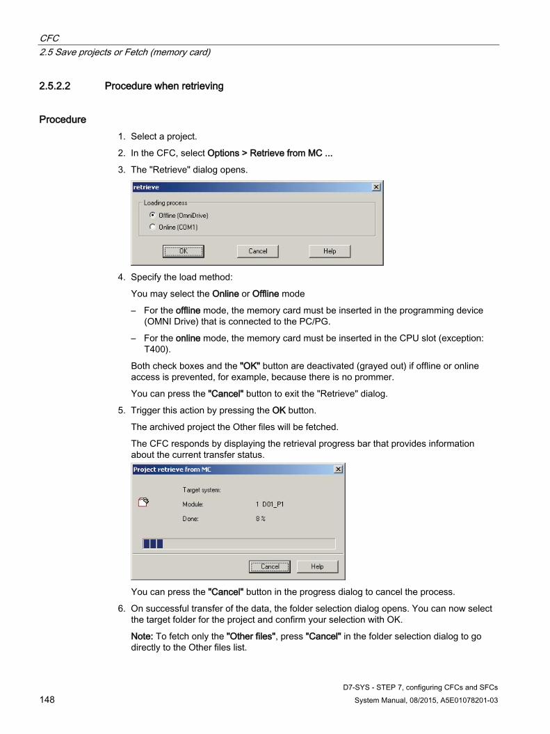
CFC 2.5 Save projects or Fetch (memory card)
D7-SYS - STEP 7, configuring CFCs and SFCs 148 System Manual, 08/2015, A5E01078201-03
2.5.2.2 Procedure when retrieving
Procedure 1. Select a project.
2. In the CFC, select Options > Retrieve from MC ...
3. The "Retrieve" dialog opens.
4. Specify the load method:
You may select the Online or Offline mode
– For the offline mode, the memory card must be inserted in the programming device (OMNI Drive) that is connected to the PC/PG.
– For the online mode, the memory card must be inserted in the CPU slot (exception: T400).
Both check boxes and the "OK" button are deactivated (grayed out) if offline or online access is prevented, for example, because there is no prommer.
You can press the "Cancel" button to exit the "Retrieve" dialog.
5. Trigger this action by pressing the OK button.
The archived project the Other files will be fetched.
The CFC responds by displaying the retrieval progress bar that provides information about the current transfer status.
You can press the "Cancel" button in the progress dialog to cancel the process.
6. On successful transfer of the data, the folder selection dialog opens. You can now select the target folder for the project and confirm your selection with OK.
Note: To fetch only the "Other files", press "Cancel" in the folder selection dialog to go directly to the Other files list.

CFC 2.5 Save projects or Fetch (memory card)
D7-SYS - STEP 7, configuring CFCs and SFCs System Manual, 08/2015, A5E01078201-03 149
7. The "Project already exists" dialog will be displayed if a project of the same name was found in the selected folder.
Press "Yes" to overwrite the project, or "Save As" to select a different folder. The folder specified with "Save As" will be checked as well. This procedure will be continued until the folder you selected was found not to contain this project
8. and the project will then be saved to that folder.
9. The dialog will be closed once the project has been unpacked and saved.
10. A dialog containing a list of the "Other files" is displayed if Other files were archived on the memory card.
Confirm with "Yes" to save these files to their original location. If files of the same name are found, a corresponding dialog opens for saving the files under a different name, or to a different folder.
Press the "No" button to open a dialog that you can use to save the files under a different name, or to a different folder.
Press "Cancel" to close the dialog and discard the files; you can fetch these from the memory card at a later time.
Siemens Industrial Spares

CFC 2.5 Save projects or Fetch (memory card)
D7-SYS - STEP 7, configuring CFCs and SFCs 150 System Manual, 08/2015, A5E01078201-03
A dialog reports the existence of files of the same name
and you will be prompted to specify a storage path for all individual files.
The path is no longer requested if you press "Yes, all".

CFC 2.6 Chart reference data documentation
D7-SYS - STEP 7, configuring CFCs and SFCs System Manual, 08/2015, A5E01078201-03 151
2.6 Chart reference data documentation This chapter describes how you can create the chart reference data for comprehensive documentation of your CFC configuration structure.
2.6.1 Chart reference data In addition to the graphic view in the CFC, you can view and print the following information in list form using the "Chart reference data" function:
● Cross-references
Listing the access to different objects.
● Run sequence
Graphic view of the entire run sequence of a CPU (see Fig. "Chart-chart reference data: Run sequence in the "CFC for S7" Manual)
This procedure allows you to check the structure of your configuration.
Cross-reference lists You can display and print the following lists of chart reference data:
● Cross-reference addresses
Lists all shared addresses used in the current CPU and the elements accessing this list.
● Cross-reference runtime groups
Lists the access actions of all CFC charts for all runtime groups of the current CPU.
● Cross reference block types
Lists the block types of the current CPU and the instances (CFCs) at which they are used.
Siemens Industrial Spares

CFC 2.6 Chart reference data documentation
D7-SYS - STEP 7, configuring CFCs and SFCs 152 System Manual, 08/2015, A5E01078201-03
2.6.2 Cross-reference lists
2.6.2.1 "Cross-reference addresses" list
List structure List of the shared addresses used in the current CPU/FM 458-1 DP, including their interconnected block I/O.
Fig. 2-6 shows the window of chart reference data and the cross-references list. Table 2-6 shows the significance of the various columns. To output this list, select Options > Chart reference data > View > Cross-reference addresses.
Figure 2-4 Chart reference data: Cross-reference addresses
Table 2- 2 Cross-references of addresses
Column heading Significance Symbol Name of the shared address Address Empty Data type Keyword for the data type used R/W Always W, i.e. write access Chart Name of the chart from which the addresses are accessed Chart element Name of the interconnected block and I/O Element comment Block comment Type Block type (e.g. INT)

CFC 2.6 Chart reference data documentation
D7-SYS - STEP 7, configuring CFCs and SFCs System Manual, 08/2015, A5E01078201-03 153
2.6.2.2 List of "Cross-references runtime groups" Lists every CFC access (block I/O) to the Enable of all runtime groups of the active CPU/FM 458-1 DP.
To output this list, select Options > Reference data > View > Cross- Runtime groups
Table 2- 3 Cross-references of runtime groups
Column heading Significance Runtime group Group name R/W Read (R) or write (W) access Chart Name of the CFC chart Chart element Name of the interconnected block and I/O Element comment Block comment Type Block type (e. g. INT)
2.6.2.3 List of "Cross-references block types" The list of block types the location at which these are use. This information may be useful for managing blocks, as you can use the cross-reference list, for example, to determine whether or not the block type you want to delete is used or not.
To output list, select Options > Reference data > View > Cross-references block types
Table 2- 4 Cross-references of block types
Column heading Significance Block type Block type name (e. g. INT) Chart Name of the CFC in which the block is used Block Name of the instance block (e. g. integrator1) Block comment Block comment
Siemens Industrial Spares

CFC 2.7 Annex
D7-SYS - STEP 7, configuring CFCs and SFCs 154 System Manual, 08/2015, A5E01078201-03
2.7 Annex
2.7.1 Field/name lengths and conventions
Table 2- 5 Name length
Object Length Comment Chart 22 *) **) The following characters are invalid:
\ . : / * ? " < > | # % Chart comment 255 All ANSI characters are allowed. Runtime group 22 Character scope as for "Chart" Task 22 Character scope as for "Chart" Block type 6 Determined by SIMATIC TDC. Block instance comment 80 All ANSI characters are allowed. Parameter name 4 Determined by SIMATIC TDC.
The first character may not be a numeral (0-9). Parameter comment 80 All ANSI characters are allowed. Block name (instance name) 16 *) **) The following characters are invalid:
\ . : / * ? " < > | # % Shared address Max. 14 Depending on the shared address type
• $ signal name 14 All ANSI characters, except ‘*’, ‘!’, and ‘$’
• Hardware address 14 All ANSI characters, except ‘*’, ‘!’, and ‘$’
• Virtual connection defini-tions
6 1. Characters: 'A' to 'Z' Additional characters: 'A' to 'Z', '0' to '9', '_'
• Symbol name 12 All ANSI characters, except space characters, ‘*’, ‘!’, ‘$’, '#', and '"'
• Sequence number 4 "1" ... "9999"
• Name reference 6 1. Characters: 'A' to 'Z' Additional characters: 'A' to 'Z', '0' to '9', '_'
• Module name 6 1. Characters: 'A' to 'Z' Additional characters: 'A' to 'Z', '0' to '9', '_' or "0"
• Connector element name 3 1. Characters: 'A' to 'Z' Additional characters: 'A' to 'Z', '0' to '9', '_'
*): The chart plus block name string may not exceed a length of 24 characters, including the separator **): If the compiler option "Generate address list" is activated, the names used must be compliant with the naming conven-tion of STRUC V4.2: 1. Characters: 'A' to 'Z'. Additional characters: 'A' to 'Z', '0' to '9', '_'

CFC 2.7 Annex
D7-SYS - STEP 7, configuring CFCs and SFCs System Manual, 08/2015, A5E01078201-03 155
2.7.2 Data types
Table 2- 6 Data types
Abbr. Keyword Designation Bits BO BOOL Logical number 8 BY BYTE 8-bit sequence 8 DI DINT Double integer 32
DW DWORD 32-bit sequence 32 GI GLOBAL For interconnections with shared addresses - I INT Integer 16 R REAL Floating-point number 32 S STRING String of any length 200 bytes
TS SDTIME High-resolution time period in SIMATIC TDC format 32 W WORD 16-bit sequence 16
2.7.3 Abbreviations AS Automation device UP User program OCM Operator Control and Monitoring (WinCC) CFC Continuous Function Chart CPU Central Processing Unit FB Function block IBS Commissioning IEC International Electrical Commission MPI Multi-Point Interface MS Microsoft OS Operator Station PC Personal computer PG Programming device SFC Sequential Function Chart SINEC Siemens Network Architecture PLC Programmable Logic Controller STEP 7 Software development environment for SIMATIC S7/M7
Siemens Industrial Spares

CFC 2.7 Annex
D7-SYS - STEP 7, configuring CFCs and SFCs 156 System Manual, 08/2015, A5E01078201-03
D7-SYS - STEP 7, configuring CFCs and SFCs System Manual, 08/2015, A5E01078201-03 157
SFC 3
Introduction [SD] This section is supplementary documentation for SIMATIC TDC and contains only the differences and special features in comparison to the S7 target system.
For more information, refer to the SFC Online Help for the S7 target system and to Start > Simatic > Documentation > English > SFC Manual for S7.
Restrictions and expansions [SD] Data types
The CHAR, DATE, S5TIME, STRING, TIME, and TIME_OF_DAY data types are invalid in SIMATIC TDC. Data type SDTIME, TS is included.
Shared addresses
In SIMATIC TDC it is not allowed to use shared addresses in the SFCs as addresses for step assignments or transition comparisons.
Alarms
SFCs do not generate messages in the SIMATIC TDC target systems.
Runtime properties
In SIMATIC TDC, the installation location of a chart is irrelevant for its processing; the runtime properties of the chart are defined based on the installation location of the assigned function block (type: SFC) that must be configured for all SFCs.
Siemens Industrial Spares

SFC 3.1 SFC basics
D7-SYS - STEP 7, configuring CFCs and SFCs 158 System Manual, 08/2015, A5E01078201-03
3.1 SFC basics
SFC in the STEP 7 environment [SD] The following STEP 7 components are of significance when working with the SFC for SIMATIC TDC:
SIMATIC Manager is used to create and edit project structures (SIMATIC TDC stations, CFCs, SFCs), to start the CFC or SFC editor, and to compile charts.
The following diagram shows how the CFC and SFC are embedded in the STEP 7 environment:
SFC and plant hierarchy [SD] The plant hierarchy is not supported for SIMATIC TDC.
Creating the project structure [SD] In contrast to SIMATIC S7, the PCS7 and S7 Wizard is not supported for SIMATIC TDC. Create a new project using the corresponding menu commands.
What are chart elements? [SD] The elements of an SFC in SIMATIC TDC are the same as the ones used in SIMATIC S7. However, by contrast to [S7], you cannot access other SFCs or shared addresses of the user program.

SFC 3.2 Tips & tricks
D7-SYS - STEP 7, configuring CFCs and SFCs System Manual, 08/2015, A5E01078201-03 159
3.2 Tips & tricks
3.2.1 Creating reference data [SD] Reference data cannot be created for SIMATIC TDC. The display functionality is therefore unavailable.
3.2.2 Configuring SFC calls [SD]
Hierarchic SFC calls The configuration of hierarchic SFC calls for SIMATIC TDC differs slightly compared to SIMATIC S7, as the SFCs do not have an EN connection. Instead, you must reference the I/O of the corresponding SFC block (in the CFC).
In order to control the "SFC-Slave1" and "SFC-Slave2" charts by means of "SFC-Coord", configure the calls (let us assume that the SFC block for "SFC-Slave1" is configured as "Slave1" and the SFC block for "SFC-Slave2" as "Slave2" in the "SFCs" CFC) as follows:
● The preceding transition of the step that is to activate "SFC-Slave1" must verify that "SFC-Slave1" has terminated. This ensures that the following condition is met as specified in the transition properties dialog:
– SFCs.Slave1.QRU = 0
● The step to activate the "SFC-Slave1" must generate a positive edge at input RUN of the corresponding block. The following operations in the properties dialog trigger the relevant response:
– In the "Initialization" tab:
SFCs.Slave1.RUN = 1
– In the "Edit" tab:
SFCs.Slave1.RUN = 1
– In the "Exit" tab:
SFCs.Slave1.RUN = 0
● The successive transition must ensure that "SFC-Slave1" has been terminated; i.e. the transition contains the following condition in its properties dialog box:
– SFCs.Slave1.QRU = 0
SFC-Slave2 is controlled accordingly by means of SFC-Coord.
The above presentation is only valid if the slaves are running in automatic mode. Additional states that can also be processed may be assumed in manual mode.
Coordinating SFCs In contrast to SIMATIC S7, SIMATIC TDC does not provide tags that exist independently of a function block (singular data cells). For this reason, you must use the I/O of dummy blocks (e. g. NOP1_B) that are capable of handling the same function.
Siemens Industrial Spares

SFC 3.3 Creating sequential control systems (SFC Editor)
D7-SYS - STEP 7, configuring CFCs and SFCs 160 System Manual, 08/2015, A5E01078201-03
3.3 Creating sequential control systems (SFC Editor)
3.3.1 Copying charts [SD] The function for copying charts in SIMATIC TDC is similar to that in the SIMATIC S7 target system.
3.3.2 Configuring sequential control systems
3.3.2.1 Creating jumps [SD] You create and edit jumps in SIMATIC TDC in the same way as in the SIMATIC S7 target system. However, all jumps to and from parallel sequences are rejected in the subsequent compilation as errors.
3.3.2.2 Step: Editing addresses [SD] The left address may be:
● A block input that is not interconnected with a CFC
Syntax: <path name>.<block name>.<connection name>
● A runtime group (activating/deactivating)
Syntax: <group name>.EN (enable)
The right address may be:
● A block connection to a CFC
Syntax: <path name>.<block name>.<connection name>
● A runtime group (activated/deactivated state)
Syntax: <group name>.EN (enable)
● A constant
Syntax: Depending on the data type
You can use symbolic representations ( value names) instead of the absolute numerical values for the BOOL, BYTE, INT, DINT, WORD, and DWORD data types.
SFC 3.3 Creating sequential control systems (SFC Editor)
D7-SYS - STEP 7, configuring CFCs and SFCs System Manual, 08/2015, A5E01078201-03 161
Selecting addresses You can edit or select the addresses for the operations in an additional dialog. Press “Browse...” to open this dialog. The third option is to drag-and-drop the block I/O from the CFCs directly to the address field.
The “Search...” dialog contains the following two tabs: "CFCs" and "Runtime groups". The search result (e.g. CFCs) shows all objects found to be available in the chart folder.
You may use the "Filter" button to limit the list of I/Os, i.e. to display only the objects that are relevant to the current configuration.
Select a chart and then select a block and the I/O from that chart. Click "Apply" button (or use drag-and-drop) to enter your selection in the current address field. The dialog remains open until you close it explicitly with "Close" and at the latest when the "Object Properties" dialog is closed.
Note
Access to CFC blocks may also be modified in the corresponding CFC. However, this modification is restricted to the "rewiring" of SFC access, which means that the access operation is moved to a different block connection (using ALT + drag&drop).
Value identifiers To enable the display of value identifiers in the SFC, select Options > Customize > Layout... and set the "parameter: Value identifiers" option.
If you insert a block I/O with value identifier in the address field, the value identifier is also entered in the right (empty) address field. If there is more than one value identifier for this connection, you can open the combo box that contains the value identifiers in the right address field by pressing the ALT+ARROW DOWN keystroke. You can select the required value identifier for this address from the drop-down list box.
Editing addresses When making textual entries, make sure that the names are consistent. A symbol that does not exist in the symbol list (or a symbol that is renamed after referencing) cannot be validated in the editor and is assumed to be correct for the time being. Such inconsistencies are disclosed during the compilation or consistency check.
Siemens Industrial Spares

SFC 3.3 Creating sequential control systems (SFC Editor)
D7-SYS - STEP 7, configuring CFCs and SFCs 162 System Manual, 08/2015, A5E01078201-03
Notes ● In the addresses, you can enter access to CFC block I/Os whose block does not yet exist
in reality in the CFC chart, but that does exist as block type in the block folder of the S7 program. These operations are displayed in the operations line on a yellow background, while the "virtual" block is listed in the CFC catalog of "Unplaced blocks".
● When entering a virtual reference, you can specify a block name that is not yet known in the CFC chart in the operation. However, the specified block I/O must actually exist in a block type contained in the block folder. A list of the block types that have this I/O is displayed in the "Select address type" dialog. After you have selected the block type, the CFC creates a block instance and stores it in the CFC catalog of "Unplaced blocks". This block instance is identified in the catalog by the index “R" (R = reference). The same layout and identifier is also used if a previously real reference becomes a virtual reference when the referenced block is deleted.
● Before you compile the data, these virtual accesses must be converted to real accesses (in other words, the relevant block must be placed in the CFC), or else compilation is stopped with an error.
EN attributes The operation "<run-time group>.EN := ON" is used to start a runtime group. A runtime group is de-activated using the "<runtime group>.EN := OFF" operation. You can therefore activate or deactivate the processing of the CFC blocks and SCFs in a runtime group with a single operation.
Notes ● The operations you enter are checked for consistency so that the correct syntax and
semantic formulation is ensured. This check, for example, determines whether the data types of the logically linked addresses are compatible.
● If an address entered is identified as unknown address type, a dialog is opened in which you can enter more detailed information. In this dialog, you can assign the address the CFC access, SFC, runtime group, or symbol type, including the corresponding data type. You can save your entry with “OK”, but it cannot be compiled until the address has been defined (i.e., this results in an error message).
Go to point of use If you want to see where an address is used, select the address (or place the cursor in the field associated with the address) and click on the “Go to” button to jump to the relevant chart (or double-click on the address). If the address is an input or output of a block in the CFC, the relevant block is selected.
The "Go To" function cannot be used for runtime groups.

SFC 3.3 Creating sequential control systems (SFC Editor)
D7-SYS - STEP 7, configuring CFCs and SFCs System Manual, 08/2015, A5E01078201-03 163
3.3.2.3 Transition: Editing addresses [SD] You can enter the addresses in text format, or as specified in "Step: Editing addresses" by means of the "Search" selection dialog. You should preferably us the selection dialog to enter the addresses, as these entries will always be unique. As a third option is to drag-and-drop the block I/Os from the CFCs directly to the address field.
As when selecting addresses for the steps, you can also enter the value identifiers of the I/Os for the transitions (see there).
If you make a selection in a CFC using the "Search" function or drag-and-drop, the entries will be extended with the path of the plant hierarchy (if this exists). The hierarchy path and chart name are separated by a double backslashes ( \\ ).
Note
Access to CFC blocks may also be modified in the corresponding CFC. However, this modification is restricted to the "rewiring" of SFC access, which means that the access operation is moved to a different block connection (using ALT + drag&drop).
EN attribute Using the condition
● <runtime group>.EN = ON
● <runtime group>.EN = OFF
you can query whether a runtime group is activated or deactivated.
Note
The conditions you enter are checked for consistency so that correct syntax and semantic formulation of the conditions is guaranteed. The check determines whether the data types of the logically linked addresses are compatible.
The pre-configured link logic is adequate in most cases. If you need more complex formulations, you can create these with blocks in a CFC and enter the results calculated in the chart as the address for transition conditions.
Go to point of use If you want to see where an address is used, select the address (or set the cursor in the address field) and click “Go To” button to jump to the relevant chart. If the address is an input or output of a block in the CFC, the relevant block is selected.
The "Go To" function cannot be used for runtime groups.
Siemens Industrial Spares
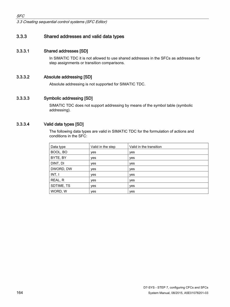
SFC 3.3 Creating sequential control systems (SFC Editor)
D7-SYS - STEP 7, configuring CFCs and SFCs 164 System Manual, 08/2015, A5E01078201-03
3.3.3 Shared addresses and valid data types
3.3.3.1 Shared addresses [SD] In SIMATIC TDC it is not allowed to use shared addresses in the SFCs as addresses for step assignments or transition comparisons.
3.3.3.2 Absolute addressing [SD] Absolute addressing is not supported for SIMATIC TDC.
3.3.3.3 Symbolic addressing [SD] SIMATIC TDC does not support addressing by means of the symbol table (symbolic addressing).
3.3.3.4 Valid data types [SD] The following data types are valid in SIMATIC TDC for the formulation of actions and conditions in the SFC: Data type Valid in the step Valid in the transition BOOL, BO yes yes BYTE, BY yes yes DINT, DI yes yes DWORD, DW yes yes INT, I yes yes REAL, R yes yes SDTIME, TS yes yes WORD, W yes yes

SFC 3.3 Creating sequential control systems (SFC Editor)
D7-SYS - STEP 7, configuring CFCs and SFCs System Manual, 08/2015, A5E01078201-03 165
3.3.4 Runtime properties
3.3.4.1 Overview of the runtime properties [SD] In SIMATIC TDC, the installation location of a chart is irrelevant for its processing; the runtime properties of the SFC are defined based on the installation location of the assigned function block (type: SFC) that must be configured for all SFCs.
The runtime properties of the SFC block determine how the SFC behaves in the time-based processing sequence within the target system structure. These properties are decisive for the behavior of the target system in terms of response times, deadtimes, or the stability of time-dependent structures, e.g. control loops.
The runtime properties are specified with the help of the “Runtime properties dialog”.
SFC function blocks may be installed in runtime groups and therefore inherit the attributes of the runtime group (reduction ratio, phase offset).
Note
SIMATIC TDC support only the following constant values: • Reduction ratio = 1 • Phase offset = 0
3.3.4.2 Specifying the run sequence [SD] There are various ways of editing the run sequence of SFCs. The run sequence encompasses the position of the corresponding SFC blocks in the tasks and runtime groups.
Siemens Industrial Spares

SFC 3.3 Creating sequential control systems (SFC Editor)
D7-SYS - STEP 7, configuring CFCs and SFCs 166 System Manual, 08/2015, A5E01078201-03
3.3.4.3 Installing SFCs in a task / deleting SFCs from a task [SD] The programming system automatically integrates each SFCs into a task. Redundant integration is neither necessary as in SIMATIC S7, nor is it possible. In addition to each SFC, a SFC function block must be integrated in a CFC whose input SFC must be tagged with the name of the SFC.
This block carries the SFC functionality. Based on the name configured at input SFC, it searches for the associated SFC and interprets this as program. For this reason, only the position of the block within the task is decisive for the run position of the SFC.
However, it is recommend arrange the SFC directly before the corresponding block in order to exclude misinterpretation of the position at which the SFC is processed.
In order to avoid misinterpretations with regard to the runtime properties of the SFC, you should
● you should always configure the corresponding SFC before the associated SFC block
● and when deleting, remove the SFC as well as the corresponding SFC block.
Note
If you configure an SFC block in an interrupt task, you should note that the SFC block only performs a single execution cycle each time that the task is activated.
3.3.4.4 Runtime attributes for the runtime group and SFC [SD]
Enable attributes of the SFC There is no enable attribute for an SFC in SIMATIC TDC. You can use input EN of the corresponding SFC function block (on=1, off=0) instead.
Runtime attributes of the runtime group In SIMATIC TDC, the installation location of a chart is irrelevant for its processing; the runtime properties of the chart are defined based on the installation location of the assigned function block (type: SFC) that must be configured for all SFCs. This block may be installed in a runtime group.
You can activate and deactivate a runtime group by means of the Enable attribute.
Attributes
● The reduction ratio and
● phase offset
cannot be directly assigned to an SFC and instead has to be assigned by implementing the corresponding function block in a runtime group from which it inherits the configured attributes. However, SIMATIC TDC allows only the reduction ratio 1 and phase offset 0.
To execute SFC blocks of a CPU with different runtime attributes you must implement these in different runtime groups.

SFC 3.3 Creating sequential control systems (SFC Editor)
D7-SYS - STEP 7, configuring CFCs and SFCs System Manual, 08/2015, A5E01078201-03 167
The object properties cannot be opened in the run sequence for the selected SFC, as the SFC has no (dynamic) runtime properties of its own.
To create a runtime group in the run sequence window (opened with Edit > Run sequence...) select menu command Insert run sequence..., or click the "Run sequence" toolbar icon.
Enter the name, a comment, as well as the runtime attribute for the reduction ratio and phase offset in the dialog.
Install the SFC block in the runtime group as usual (similar to a task).
Note
You can implement SFC blocks in runtime groups to enable their execution in different cyclic tasks. and therefore improve the project structure under the aspect of the technology.
Siemens Industrial Spares

SFC 3.3 Creating sequential control systems (SFC Editor)
D7-SYS - STEP 7, configuring CFCs and SFCs 168 System Manual, 08/2015, A5E01078201-03
3.3.5 Message response of the SFC [SD] SFCs do not generate messages in the SIMATIC TDC target systems.
3.3.6 Compiling charts
3.3.6.1 Compiler settings [SD] Select Options > Customize > Compile to open the corresponding dialog and make the following settings:
1. A temporary folder to which interim files generated by the compiler are saved?
2. Create an address book?
Note: If you activate this option, the compiler verifies compliance of the chart, block and $ signal names with naming conventions specified in STRUC V4.2.
1. Generate a mapping list for the user program you created?
2. Which function block types can be inserted in the CFC online test mode?
– Only configured block types
– Block types in the "FBSLIB" standard library
– Block types from all imported libraries
Default hardware In this area, specify the hardware for which to import block libraries to a chart folder without hardware assignment in HW Config:
● Select the “SIMATIC TDC” check box if you want to configure SIMATIC TDC components.
● Clear the “SIMATIC TDC” check box if you want to configure SIMADYN D components.
Note
The block libraries that are suitable for the hardware are imported automatically for chart folders with hardware assignment.
Creating a global I/O file Select the “All I/O” check box if you want to create a file that contains all I/O.

SFC 3.3 Creating sequential control systems (SFC Editor)
D7-SYS - STEP 7, configuring CFCs and SFCs System Manual, 08/2015, A5E01078201-03 169
Creating a file for string connections Select the “String I/O” check box if you want to generate a file that only contains the string connections.
Note
The procedure for “Compiler customization [SD]” is identical with that for the CFC.
3.3.6.2 Compilation procedures [SD] How to compile configured charts:
1. Select the Chart > Compile as program... menu command or click the toolbar icon.
A dialog opens in which you can select the "complete program" check box to compile all charts, or the "changes only" check box to compile only the objects that changed since the last compilation, or compile an individual SFC.
2. Select the compilation scope, i.e. "Compile all", "Compile only changes", or “Only compile individual SFC”. In the latter case, select the SFC to be compiled from the drop-down list box. Click "OK" to start compilation.
A consistency check verifies all charts of the current program (chart folder) within the selected compilation scope and compilation will start if no errors were found.
A dialog displays a compilation progress bar. You may cancel compilation at any time with “Cancel”.
Log files The result of the consistency check and all messages output during compilation can be viewed and printed using the "Logs” dialog (menu command Options > Logs...).
Note
You may also run a consistency check without compilation by select the Chart > Consistency check... menu command.
Siemens Industrial Spares
SFC 3.3 Creating sequential control systems (SFC Editor)
D7-SYS - STEP 7, configuring CFCs and SFCs 170 System Manual, 08/2015, A5E01078201-03
3.3.6.3 Consistency check [SD] Prior to the actual compilation, the system automatically checks the consistency of the SFCs along with the CFC compilation:
● Verifies the availability of all blocks accessed by SFC conditions or operations.
● Verifies that the target names that were specified for jumps correspond with the step names in the same SFC.
● Verifies that jumps do not point to simultaneous branches.
You may run these consistency checks without subsequent compilation, for example, to decide whether or not a compilation appropriate.
Proceed as follows:
1. Select the Chart > Consistency check... menu command.
The check covers all charts of the current chart folder.
2. The result of consistency check is displayed in the "Logs" dialog. You may view or print the log at a later time by selecting the Options > Logs... menu command in the SFC, or Options > Charts > Logs... in SIMATIC Manager.
Note
The procedure for the “Consistency check [SD]” is identical with that for the CFC.

SFC 3.3 Creating sequential control systems (SFC Editor)
D7-SYS - STEP 7, configuring CFCs and SFCs System Manual, 08/2015, A5E01078201-03 171
3.3.7 Loading user programs
3.3.7.1 Loading programs [SD] To enable execution of a user program on a CPU, it must first be loaded.
The user program you compiled based on the CPU charts is downloaded to the particular CPU that is assigned the active chart window. On completion of its download to program memory of the CPU, the user program is not yet active.
You must restart the CPU in order to activate the new CPU program (refer to Viewing and changing operating states).
The user program can be loaded in offline or online mode.
Proceed as follows to load the user program:
1. Select PLC > Download...
2. The "Load" dialog opens.
3. Define the scope of the software to load:
– Usually, it is sufficient to load only the configured software ("Only user program ") in order to save time on loading. However, if the CFC detects that the operating system version has changed since the last time that data was downloaded to this CPU, the new operating system version is included automatically in the download.
– If you have not yet downloaded a software to the CPU, you must download the complete software ("system and user program") to the CPU.
– A single SFC that you edited and compiled can be downloaded in online mode by selecting the “online” and “only individual SFC” check boxes. Select the SFC that still needs to be downloaded from the drop-down list box.
4. Specify the mode for PC access to program memory:
– In the commissioning phase, the memory module containing the user program usually remains in the CPU and you select the "online" option accordingly.
– When working in "offline" mode, you must remove the memory card from the CPU and insert it in a PCMCIA slot on your PC.
5. Trigger the Load function to run the download. The CFC responds by displaying the load progress bar.
6. On successful completion of the download, the new user program is installed in program memory of the CPU and is activated at the next station restart.
Note
The procedure when “Downloading programs [SD]” is identical with that of CFC.
Siemens Industrial Spares

SFC 3.4 Sequential control systems in the AS
D7-SYS - STEP 7, configuring CFCs and SFCs 172 System Manual, 08/2015, A5E01078201-03
3.4 Sequential control systems in the AS
3.4.1 Overview of sequential control systems in the AS [SD] With SIMATIC TDC:
● No control block in the context of S7, but an SFC function block (block type: SFC) that must be configured for all SFCs.
By principle, no phase offset or reduction ratio for runtime groups, as only the following constant values are valid:
● Reduction ratio = 1
● Phase offset = 0
3.4.2 Runtime behavior [SD] Cyclic interrupts are implemented in SIMATIC TDC as interrupt tasks.
The operating system evaluates specific events and processes the SFC according to these events. Such events are, e.g.:
● Restart
The SFC is called automatically for initialization.
● Interrupt tasks
The SFC is executed in the interrupt task in which it was configured using the run sequence editor.
You must explicitly assign an SFC to the events by means of the run sequence editor, i.e. the chart must be implemented in the corresponding task (directly, or in runtime groups). Call in the SFC: Edit -> Run Sequence...
3.4.3 Operating modes [SD] The following operating modes can be configured using the SFC block:
● Manual and
● Auto

SFC 3.4 Sequential control systems in the AS
D7-SYS - STEP 7, configuring CFCs and SFCs System Manual, 08/2015, A5E01078201-03 173
3.4.4 Runtime options [SD] The behavior of SIMATIC TDC corresponds to that of SIMATIC S7.
What are runtime options? The individual runtime options specify the chart behavior and may be combined. The following runtime options are available and may be edited in the "Chart > Properties: AS operating parameters":
Command output ● With "command output: on" actions of active steps will be processed.
● With "command output: off", actions of active steps will not be processed.
During installation and commissioning, or if errors occur, blocking command output in conjunction with certain operating modes, can bring the sequential control system into a defined state without influencing the process.
Cyclic mode ● With "cyclic mode: on”, the initial step of the SFC is reactivated after the final step has
been deactivated.
● With "cyclic mode: Off”, the sequential control system is set to the "OFF" state after the final step has been deactivated, which means that all steps are deactivated and no further actions and transitions will be processed.
Time monitoring ● With "time monitoring: On”, the activation time of the step is compared with the monitoring
time (object properties of the step, "General" tab, "Maximum runtime" option) and a step error is signaled on timeout.
● With "time monitoring: off", the activation and monitoring times are not compared.
Autostart The chart assigned the "Autostart: On” property starts immediately after a CPU restart without any further operator action. On completion of a delta download (the CPU does not go into STOP), the SFC is not started automatically and must be restarted by the operator, or by means of the control block.
The "Autostart" setting can only be edited in the Chart > Properties > Tab: Operating parameters dialog.
Using default operating parameters for SFC startup You can select the "Use default operating parameters when SFC starts" On" runtime option to restore all default settings / options that were set in the runtime properties at the start of the SFC. e.g. options changed in test mode.
Siemens Industrial Spares

SFC 3.4 Sequential control systems in the AS
D7-SYS - STEP 7, configuring CFCs and SFCs 174 System Manual, 08/2015, A5E01078201-03
3.4.5 Behavior of the sequential control system [SD] The behavior of a sequential control system depends on the operating parameters: Operating state and mode, activation mode, and runtime options.
You can set the operating parameters when testing and commissioning (with the exception of “Auto start”); this parameter can only be set in the Chart properties dialog, "AS operating parameters" tab).
Default settings of the AS operating parameters ● Manual mode (operating mode)
● Step control mode T (process control)
● Runtime options:
– Command output: On
– Cyclic mode: Off
– Time monitoring: Off
● Additional options
– Autostart: Off
– Using default operating parameters for SFC startup
The following operating mode is set after startup of the AS:
● Operation state
– OFF (if Autostart = off)
– ON (if Autostart = on)
Startup behavior [SD] The start behavior of the SFC depends on the chart properties.
● Auto mode
The SFC block parameters are used at the start.
● Manual mode
The defaults of the SFC block, or the current SFC parameters, are used at the start.
The actual values will be retained or overwritten with the defaults, depending on the settings in (Chart > Properties: AS operating parameters), or in the test mode with the option: "Use default operating parameters at SFC start".

SFC 3.4 Sequential control systems in the AS
D7-SYS - STEP 7, configuring CFCs and SFCs System Manual, 08/2015, A5E01078201-03 175
3.4.6 Operating states [SD] Refer to the SFC help for the SIMATIC S7 target system.
Note
The SFC block takes over the function of the control block (SFC_CTRL) in SIMATIC TDC.
3.4.7 Commands [SD] The behavior of SIMATIC TDC corresponds to that of SIMATIC S7.
What is the effect of the commands? In test mode, you can set or modify the operating states using the following commands:
Start / Resume
Meaning of "Start" This command changes the sequential control system from the “IDLE”, "ABORTED", or "END", to the “RUN” state. This means that the chart is processed immediately. The initial step is activated automatically, its actions are executed, and the results of the successor transitions are evaluated.
Exception: If a step was selected as target step in test mode, the target step will be activated instead of the start step on execution of the "Start" command.
Meaning of "Resume" This command changes the sequential control system from the “HOLD” to the ”RUN” state. This means that the SFC is continued, transition results are evaluated, the actions are executed and the chart progresses according to the selected step control mode.
Exception: If a step was selected as the target step in the test mode and the "Resume" command is set, the interrupted SFC is resumed after the interrupted steps have been properly processed. This means that cyclic processing of these steps is executed only once more and that the termination process overlaps initialization of the target step in the same cycle.
Abort This command changes the sequential control system from the “HOLD” to the ”ABORT” state. The active steps will be completed and the final step is processed subsequently. Existing target step selections will be ignored and deleted.
This allows the sequential control system to be brought into a defined state.
Siemens Industrial Spares
SFC 3.4 Sequential control systems in the AS
D7-SYS - STEP 7, configuring CFCs and SFCs 176 System Manual, 08/2015, A5E01078201-03
Hold This command sets the sequential control system from the “RUN” to the ”HOLD” state. This means that the SFC has stopped, transition results are not evaluated, actions are not executed, and a command must be set to enable continuation of the chart.
Restart This command changes the sequential control system from the “HOLD” to the ”RUN” state. The active steps will be deactivated, the initial step is activated and its actions are executed.
3.4.8 Runtime phases of a step [SD] In SIMATIC TDC, there is no difference compared to the SIMATIC S7 target system.
3.4.9 Processing steps and transitions [SD] In SIMATIC TDC, there is no difference compared to the SIMATIC S7 target system.
3.4.10 Controlling with control block
Control block [SD] The SFC block takes over the function of the control block in SIMATIC TDC.
Control block inputs [SD] The SFC block takes over the function of the control block in SIMATIC TDC.
Control block outputs [SD] The SFC block takes over the function of the control block in SIMATIC TDC.

SFC 3.5 Documentation of programs
D7-SYS - STEP 7, configuring CFCs and SFCs System Manual, 08/2015, A5E01078201-03 177
3.5 Documentation of programs
3.5.1 Log files [SD] The log files are not part of the complete documentation of the configuration structure, but may provide important information during configuring (engineering) and commissioning, for example, if errors have occurred.
The tab described here are also relevant for the SFCs.
Creating logs Select Options > Logs... to open a dialog with several tabs. These tabs are only available if the corresponding functions were actually executed.
You can print the messages using the “Print” button. Select “Page setup” to define the layout.
Tab: Compile Contains a list of messages that were output during the compilation or consistency check (including the compiler messages); e.g. if a jump to target was not available: "Error in transition ‘3’: The specified jump target is not available in the SFC".
Siemens Industrial Spares

SFC 3.5 Documentation of programs
D7-SYS - STEP 7, configuring CFCs and SFCs 178 System Manual, 08/2015, A5E01078201-03

D7-SYS - STEP 7, configuring CFCs and SFCs System Manual, 08/2015, A5E01078201-03 179
Service & Support A A.1 Service & Support
The unmatched complete service for the entire life cycle For machine constructors, solution providers and plant operators: The service offering from Siemens Industry Automation and Drive Technologies includes comprehensive services for a wide range of different users in all sectors of the manufacturing and process industry.
To accompany our products and systems, we offer integrated and structured services that provide valuable support in every phase of the life cycle of your machine or plant – from planning and implementation through commissioning as far as maintenance and modernization.
Our Service & Support accompanies you worldwide in all matters concerning automation and drive technology from Siemens. We provide direct on-site support in more than 100 countries through all phases of the life cycle of your machines and plants.
You have an experienced team of specialists at your side to provide active support and bundled know-how. Regular training courses and intensive contact among our employees – even across continents – ensure reliable service in the most diverse areas
Siemens Industrial Spares

Service & Support A.1 Service & Support
D7-SYS - STEP 7, configuring CFCs and SFCs 180 System Manual, 08/2015, A5E01078201-03
Online Support The comprehensive online information platform supports you in all aspects of our Service & Support at any time and from any location in the world.
You can find Online Support on the Internet at the following address: Internet (http://www.siemens.com/automation/service&support).
Technical Consulting Support in planning and designing your project: From detailed actual-state analysis, definition of the goal and consultation on product and system questions right through to the creation of the automation solution.
Technical Support Expert advice on technical questions with a wide range of demand-optimized services for all our products and systems.
You can find Technical Support on the Internet at the following address: Internet (http://www.siemens.com/automation/support-request).
Training Extend your competitive edge – through practical know-how directly from the manufacturer.
You can find the training courses we offer on the Internet at the following address: Internet (http://www.siemens.com/sitrain).
Engineering Support Support during project engineering and development with services fine-tuned to your requirements, from configuration through to implementation of an automation project.
Field Service Our Field Service offers you services for commissioning and maintenance – to ensure that your machines and plants are always available.
Spare parts In every sector worldwide, plants and systems are required to operate with constantly increasing reliability. We will provide you with the support you need to prevent a standstill from occurring in the first place: with a worldwide network and optimum logistics chains.
Repairs Downtimes cause problems in the plant as well as unnecessary costs. We can help you to reduce both to a minimum – with our worldwide repair facilities.

Service & Support A.1 Service & Support
D7-SYS - STEP 7, configuring CFCs and SFCs System Manual, 08/2015, A5E01078201-03 181
Optimization During the service life of machines and plants, there is often a great potential for increasing productivity or reducing costs.
To help you achieve this potential, we are offering a complete range of optimization services.
Modernization You can also rely on our support when it comes to modernization – with comprehensive services from the planning phase all the way to commissioning.
Service programs Our service programs are selected service packages for an automation and drives system or product group. The individual services are coordinated with each other to ensure smooth coverage of the entire life cycle and support optimum use of your products and systems.
The services of a Service Program can be flexibly adapted at any time and used separately.
Examples of service programs:
● Service contracts
● Plant IT Security Services
● Life Cycle Services for Drive Engineering
● SIMATIC PCS 7 Life Cycle Services
● SINUMERIK Manufacturing Excellence
● SIMATIC Remote Support Services
Advantages at a glance:
● Reduced downtimes for increased productivity
● Optimized maintenance costs due to a tailored scope of services
● Costs that can be calculated and therefore planned
● Service reliability due to guaranteed response times and spare part delivery times
● Customer service personnel will be supported and relieved of additional tasks
● Comprehensive service from a single source, fewer interfaces and greater expertise
Contact At your service locally, around the globe: your partner for consultation, sales, training, service, support, spare parts... for the entire range of products supplied by Industry Automation and Drive Technologies.
You can find your personal contact in our contacts database at: Internet (http://www.siemens.com/automation/partner).
Siemens Industrial Spares

Service & Support A.1 Service & Support
D7-SYS - STEP 7, configuring CFCs and SFCs 182 System Manual, 08/2015, A5E01078201-03

D7-SYS - STEP 7, configuring CFCs and SFCs System Manual, 08/2015, A5E01078201-03 183
Index
$ $ signals, 67, 100, 100
Bus, 100 Interconnectability, 100 Type, 100
A Activating
Test mode, 130 Archive file, 85 Archiving program
Properties, 85 Archiving programs, 85 Archiving projects, 86 Assigning I/O addresses, 48 Assigning parameters
Block I/O, 124, 134 Block I/O, 124, 134 inputs, 119
B Backing up the project, 41 Block catalog
Opening, 117 Block I/O
$ signals, 100, 100 Assigning parameters, 124, 134 Configuring OCM attributes, 107 Hardware addresses, 102 Hardware interrupts, 103 Module names, 102 Monitoring, 124, 132 Name references, 103 OP connection, 102 Properties, 97 Virtual connection identifiers, 101 Virtual connections, 101
Block inputs Editing, 97 Inverting, 97
Block interconnections, 98 Block library
Check, 94
Creating, 139 Importing, 94
Block outputs Values, 97
Block types Creating, 139 Handling, 94 Help, 119 Inserting, 95
Blocks Deleting, 122, 136 Editing, 118 Inserting, 117, 122, 136 Interconnecting, 118 Operating control and monitoring, 106
Bootstrapping, 111 Bus
$ signals, 100
C CFC
Embedded, 91 Opening, 117 Starting, 117
Changing Between the test and edit modes, 128 Run sequence, 118
Chart Printing, 123
Chart reference data, 123, 151 Check
Block library, 94 Connection setup, 138
Checking consistency, 49 Communication connection
Creating, 138 Communication interface
Selecting, 138 Communication interfaces, 137 Compiling, 120
Chart as block type, 139 Multiprocessing, 110 Relations, 108 Scope, 109 Settings, 109 User program, 108
Configuration, 42
Siemens Industrial Spares
Index
D7-SYS - STEP 7, configuring CFCs and SFCs 184 System Manual, 08/2015, A5E01078201-03
Configuration data Data flow, 92
Configured service interface, 137 Configuring
Project structure, 115 Configuring object properties, 31 Configuring OCM attributes, 107 Configuring PROFINET, 52 Configuring SS52 for slave mode, 50 Connection
Deleting, 122 Restoring, 122
Connection setup Check, 138
Consistency check, 120 Chart as block type, 141
CPU Starting, 120
Crash conditions Displaying, 131
Creating Block types, 139 Communication connection, 138 Interconnections, 135 Project, 115
Creating a configuration, 42 Creating a project, 34 Creating a station, 36 Creating objects, 30 Creating software, 39 Creating the software
Procedure, 40 Cross-references
Addresses, 151, 152 Block types, 151, 153 List, 151 Runtime groups, 151, 153
D Data flow
Configuration data, 92 Description, 93
Data type, 155 GLOBAL, 97, 98 STRING, 98
Deactivating Test mode, 130
Deleting Block library, 95, 95 Blocks, 122, 136 Interconnections, 135
Diagnostics, 78 Diagnostics buffer, 81 Diagnostics events
Error classes, 79 Diagnostics in SIMATIC Manager, 80 Diagnostics in the CFC, 83 Diagnostics information, 80 Diagnostics interface, 137 Dialog, 32 Displaying
Crash conditions, 131 DOCPRO, 89 Dynamic display of values
Starting, 133
E Editing
Block inputs, 97 Blocks, 118
Editing modes, 124 Editing object properties, 31 Enable attribute, 105 Error report
Block library, 94, 95
F Field
Length, 154 Name, 154
Function groups, 124
H Hardware
Inserting, 115 Hardware addresses, 102
Block I/O, 102 Hardware interrupts, 103
Block I/O, 103 Help
Block types, 119
I Input dialogs
Shared addresses, 99 Input value
Modifying, 121

Index
D7-SYS - STEP 7, configuring CFCs and SFCs System Manual, 08/2015, A5E01078201-03 185
inputs Assigning parameters, 119
Inserting Block library, 95 Blocks, 117, 122, 136 Hardware, 115 Software, 116
Interconnectability $ signals, 100 of data types, 98
Interconnecting Blocks, 118
Interconnections, 135 Creating, 135 Deleting, 135
Inverting Block inputs, 97
L Length
Field, 154 Name, 154
Linking hardware signals in the CFC, 48 Loading
Boot, 111 Offline, 111 Online, 111 Requirements, 112 User program, 111, 120
Loading configurations, 49 Local service interface, 137
M Map listing, 109 Modifications
In test mode, 129 Modifying
Input value, 121 Refresh rate, 128 Test mode, 121
Module names, 102 Block I/O, 102
Module state, 131 Determining requirements, 131
Module status information in SIMATIC Manager, 81 Module status information in the CFC, 83 Monitoring
Block I/O, 124, 132 Test mode, 121
MPI interface, 138 MPI network
Communication bus, 27 Multiprocessing, 110
N Name
Field, 154 Length, 154
Name references, 103 Block I/O, 103
O Object hierarchy, 26 Offline loading, 73, 111
Load interface, 74 Online download, 71, 111
Interfaces, 71 Online Help, 23 OP connection, 102
Block I/O, 102 OP connection identifiers, 102
Opening objects, 30 Operating control and monitoring, 106 Operating states, 125
INIT, 125 Power off, 125 Requirements, 126 RUN, 125 STOP due to initialization error, 126 STOP due to system error, 126 User stop, 125
Operation state, 84 Overall documentation, 123
P Parameterizing, 42 Parameterizing modules, 47 Print preview, 89 Print start, 90 Printer setup, 89 Printing
Chart, 123 PROFIBUS master, 50 Programs
Assigned, 38 Non-assigned, 38
Siemens Industrial Spares

Index
D7-SYS - STEP 7, configuring CFCs and SFCs 186 System Manual, 08/2015, A5E01078201-03
Project Creating, 115
Project structure Configuring, 115
Projects, 25
R Refresh rate
Modifying, 128 Requirements
Loading, 112 Operating states, 126
Restoring Connection, 122
Retrieving projects, 88 Run sequence, 104
Changing, 118 Runtime attributes, 105 Runtime properties, 103
S Saving configurations, 49 Selecting
Communication interface, 138 Selecting modules, 47 Selecting racks, 47 Service interface
Configured, 137 Local, 137
Setup from CD-ROM, 15, 16 SFC
Absolute addressing, 164 Behavior of the sequential control system, 174 Chart element, 158 Commands, 175 Compilation procedure, 169 Compiler settings, 168 Compiling charts, 168 Configuring SFC calls, 159 Consistency check, 170 Control block, 176 Copying charts, 160 Creating a project structure, 158 Creating jumps, 160 Creating reference data, 159 Installing charts in a task / deleting charts from a task, 166 Introduction, 157 Loading the program, 171
Log files, 177 Message response, 168 Operating modes, 172 Restrictions and expansions, 157 Run sequence, 165 Runtime attributes, 166 Runtime behavior, 172 Runtime options:, 173 Shared addresses, 164 STEP 7 environment, 158 Step, edit address, 160 Symbolic addressing, 164 Transition, editing addresses, 163 Valid data types, 164
SFC runtime properties (overview), 165 SFC sequential control systems in the AS (overview), 172 Shared address, 69
Interconnection, 98 Types, 99
SIMATIC Manager, 17 Software
Inserting, 116 Requirements, 92, 92
Software containers, 28 "Charts" containers, 28
Starting CFC, 117 CPU, 120 Dynamic display of values, 133 SIMATIC Manager, 114
Station, 27 STEP 7
Components, 91
T Task runtime groups, 104 Test mode, 128
Activating, 121, 130 Deactivating, 130 Modifying, 121 Monitoring, 121
Testing programs, 76 Top chart, 140 Type
$ signals, 100
U User library, 139

Index
D7-SYS - STEP 7, configuring CFCs and SFCs System Manual, 08/2015, A5E01078201-03 187
User program Compiling, 108 Loading, 111, 120
V Virtual connection identifiers, 101
Block I/O, 101 Virtual connections, 68, 101
Block I/O, 101
W WinCC, 106
Siemens Industrial Spares

Index
D7-SYS - STEP 7, configuring CFCs and SFCs 188 System Manual, 08/2015, A5E01078201-03