OBSERVACIN AL PROYECTO DE NORMA E 060 CONCRETO ...
41
OBSERVACIÓN AL PROYECTO DE NORMA E 060 CONCRETO ARMADO Suscrita por : Ing. Enrique Pasquel C. Director Ejecutivo del Centro de Investigación Tecnológica del Cemento y el Concreto – CITEDEC 1) TEXTO OBSERVADO .- Se detalla el texto observado en el Capítulo 5 : CAPÍTULO 5 - CONCRETO EN OBRA 5.5 COLOCACIÓN 5.5.7 El vaciado de las vigas y losas no se efectuará antes que el concreto de los elementos que le sirven de apoyo haya pasado del estado plástico al sólido. El tiempo mínimo será de 3 horas después del vaciado de estos últimos. 2) DETALLE DE LA OBSERVACIÖN .- a) El texto tal como está redactado, si no se aclara, podría interpretarse que en los Edificios de Ductilidad Limitada donde se emplea el sistema industrializado de encofrado tipo túnel, no se podrían vaciar monolíticamente las losas y las placas. b) Dicha interpretación, que como sustentaremos más adelante no tiene aplicación para este tipo de sistema constructivo, produciría la alteración innecesaria del ciclo productivo, con la consecuencia del incremento en costos, y su traslado al usuario final constituido por el sector de bajos recursos en nuestro país, al que van dirigidos principalmente los Edificios de ductilidad limitada. c) Se propone un texto modificado que considere la excepción al caso mencionado. 3) SUSTENTO TÉCNICO.- 3.1) Antecedentes .- a) El texto considerado en el proyecto de norma es una traducción
Transcript of OBSERVACIN AL PROYECTO DE NORMA E 060 CONCRETO ...

OBSERVACIÓN AL PROYECTO DE NORMA E 060 CONCRETO ARMADO Suscrita por : Ing. Enrique Pasquel C.
Director Ejecutivo del Centro de Investigación Tecnológica del Cemento y el Concreto – CITEDEC
1) TEXTO OBSERVADO .-
Se detalla el texto observado en el Capítulo 5 :
CAPÍTULO 5 - CONCRETO EN OBRA 5.5 COLOCACIÓN 5.5.7 El vaciado de las vigas y losas no se efectuará antes que el concreto
de los elementos que le sirven de apoyo haya pasado del estado plástico al sólido. El tiempo mínimo será de 3 horas después del vaciado de estos últimos.
2) DETALLE DE LA OBSERVACIÖN .-
a) El texto tal como está redactado, si no se aclara, podría interpretarse que
en los Edificios de Ductilidad Limitada donde se emplea el sistema industrializado de encofrado tipo túnel, no se podrían vaciar monolíticamente las losas y las placas.
b) Dicha interpretación, que como sustentaremos más adelante no tiene
aplicación para este tipo de sistema constructivo, produciría la alteración innecesaria del ciclo productivo, con la consecuencia del incremento en costos, y su traslado al usuario final constituido por el sector de bajos recursos en nuestro país, al que van dirigidos principalmente los Edificios de ductilidad limitada.
c) Se propone un texto modificado que considere la excepción al caso
mencionado. 3) SUSTENTO TÉCNICO.- 3.1) Antecedentes .- a) El texto considerado en el proyecto de norma es una traducción

modificada del Código ACI 318-08, Capitulo 6 Cimbras, Tuberías Embebidas y Juntas de Construcción, Sub Capítulo 6.4 Juntas de Construcción¨ que en su acápite 6.4.6 dice en la versión oficial en español :
6.4.6 Las vigas, vigas principales o losas apoyadas sobre columnas o muros no
deben construirse hasta que el concreto del apoyo vertical haya endurecido hasta el punto que haya dejado de ser plástico.
d) En los comentarios del Código ACI 318-08 para este acápite se lee lo siguiente :
R6.4.6 La espera en la colocación del concreto de elementos apoyados sobre columnas y muros es necesaria para evitar fisuración en la interfase de la losa y el elemento de soporte, causado por la exudación y asentamiento del concreto plástico en el apoyo.
d) Esta disposición relativa al desfase entre el vaciado de los elementos de
soporte y los elementos horizontales figura desde la primera versión del Código ACI 318 en el año 1941 donde se fijaba en al menos 2 horas dicho desfase. Las siguientes versiones de los años 1941. 1947, 1951 y 1956 la incluyeron sin ninguna variante.
e) En la versión del año 1963 en que se introdujeron una serie de
modificaciones importantes, se eliminó la restricción de las 2 horas, introduciéndose el texto que está vigente hasta la versión actual del 2008, donde se considera sólo que haya dejado de ser plástico sin especificar un tiempo determinado, ya que ello es muy variable dependiendo del caso en particular. Un aspecto también importante es que se aclara en los comentarios, que se introducen por primera vez, que la intención es permitir que el concreto del elemento vertical se asiente de manera de prevenir fisuras en la parte inferior del sistema piso losa por asentamientos diferenciales.
f) Recién en los comentarios de la versión de 1983 se aclara que esta
disposición es necesaria para prevenir fisuras en la interfase de la losa y el elemento de soporte por exudación y asentamiento plástico.
g) El acápite que figura en la propuesta de la NTE E 060 proviene sin mayor
modificación desde las versiones anteriores de nuestra norma de concreto, representando una versión obsoleta y más conservadora que la versión original del Código ACI 318 del año 1941 y obviamente que la del 2008.
3.2) Consideraciones Técnicas.- a) El Código ACI 318 está concebido desde su origen en 1941 para normar la

construcción de estructuras de concreto con elementos aporticados (columnas y vigas) combinados con placas y losas y hace hincapié en todas sus versiones que los casos especiales deben ser analizados de manera particular o empleando los reportes específicos que desarrolla el ACI para estos casos.
b) El sistema constructivo tipo túnel se origina en los años 1950 en Francia
con la patente Outinor y se ha difundido mundialmente con gran cantidad de alternativas, siendo su característica fundamental el vaciado monolítico de losas y muros en diseños de edificaciones modulares y repetitivas, que no tienen vigas ni columnas, con lo que se logra una gran celeridad, eficiencia y economía en el proceso.
c) Este sistema está sumamente difundido también en USA y América Latina,
siendo que el ACI lo reconoce en el reporte ACI 347.2R-05 Guide for Shoring/Reshoring of Concrete Multistory Building.
d) En los sistemas tipo túnel donde sólo existen muros y losas, no se
producen los asentamientos diferenciales originados por exudación y asentamiento plástico que si existen en los sistemas aporticados. Por un lado los espesores de las losas son muy reducidos en comparación a los de las edificaciones convencionales, disminuyendo sensiblemente la magnitud de los asentamientos por exudación que son directamente proporcionales al espesor del elemento, y por otro lado, no existe la gran diferencia en masa entre el espesor de la losa y la columna o muro que es lo que ocasiona los denominados asentamientos diferenciales.
e) Otro factor particular muy importante en los Edificios de Ductilidad Limitada
que se construyen en nuestro medio, es que en los diseños de mezcla se usan incorporadotes de aire para reducir permeabilidad y darle durabilidad al concreto, con lo que se reduce o elimina la exudación, y además se

incluyen normalmente fibras de polipropileno que rompen capilaridad en el concreto y también neutralizan la exudación.
f) En el año 2005 el CITEDEC llevó a cabo una investigación en 55
proyectos de Edificios de Ductilidad Limitada para evaluar los defectos superficiales en los elementos encofrados. El trabajó se difundió en una serie de eventos Nacionales e Internacionales y se publicó en la revista de ASOCRETO la Asociación de Fabricantes de Concreto de Colombia.
g) En la investigación aludida se halló que las fisuras por asentamiento
diferencial estaban incluidas en el rubro otros constituido además por : líneas de acumulación de finos, rebabas y huellas de los encofrados, transparencia del agregado , fuga de lechada, etc. que representaron en conjunto el 0.5% de los defectos detectados.
h) Esta evaluación se llevó a cabo mediante monitoreo directo por personal
especializado y por una encuesta directa a los residentes de obra, revelándose que el problema de la fisuración en el encuentro losa-muro, en los sistemas de construcción tipo túnel no existe, o sólo ocurre en situaciones muy puntuales por coincidencia con instalaciones o por desencofrado antes que el concreto haya desarrollado la capacidad resistente especificada por el proyectista.
i) Se está desarrollando en el CITEDEC una investigación a escala natural
para medir los valores de exudación y asentamiento plástico en los sistemas tipo túnel vs los sistemas que consideran el vaciado de los muros independiente del de las losas. Se emplean encofrados comerciales disponibles en el medio en los que se ha habilitado una cara transparente para evaluar la reología de las mezclas y se monitorean temperaturas y deformaciones empleando termocuplas y transductores de desplazamiento en muros de 10 cm y losas de 12 cm. con refuerzo de acero convencional y malla electrosoldada.
j) Los primeros resultados en sistemas muros-losa monolíticos han
mostrado velocidades de exudación inferiores a 0.15kg/m2/hora tanto en la zona de muro como en la losa para concretos de f´c=175 kg/cm2 (1/3 de los valores usuales en otro tipo de estructuras) y valores de asentamiento en ambos lados del orden de 0.005mm que no producen asentamiento diferencial, comprobándose los aspectos conceptuales ya mencionados.
k) Se está adjuntando el trabajo de investigación mencionado en 3.2 f) y
artículos técnicos sobre el uso difundido a nivel internacional de los sistemas constructivos en concreto con vaciado monolítico muro-losa.

3) PROPUESTA DE NUEVO TEXTO.-
Basándonos en los antecedentes y sustento desarrollado, y con miras a actualizar la versión del acápite 5.5.7 y prevenir discrepancias y conflictos por una aplicación errada de esta limitación, proponemos el siguiente texto:
CAPÍTULO 5 - CONCRETO EN OBRA 5.6 COLOCACIÓN 5.5.7 El vaciado de las vigas y losas no se efectuará antes que el concreto
de los elementos que le sirven de apoyo haya pasado del estado plástico al sólido. Esta limitación no será aplicable en los sistemas estructurales que estén constituidos exclusivamente por muros y losas de concreto tales como los Edificios de ductilidad limitada.
Lima, 15 de Abril 2008
Ing. Enrique Pasquel C. CIP 19480

PROPUESTA DE METODOLOGÍA PARA EVALUACION DE DEFECTOS SUPERFICIALES EN LOS ACABADOS DE MUROS DE CONCRETO
Ing. Enrique Pasquel (*), Ing. Cristian Sotomayor (**)
RESUMEN El presente trabajo establece una propuesta de metodología para evaluar de manera objetiva y cuantificada, los defectos superficiales en muros de concreto de sistemas industrializados de vivienda, relacionados con factores del proceso constructivo en obra tales como el sistema de colocación y consolidación del concreto y su trascendencia tanto en los aspectos estéticos como en los estructurales de estos elementos. Para ello se desarrolló una investigación en 16 Proyectos en ejecución de edificios industrializados en concreto con muros delgados, que permitió definir parámetros de medición y control estandarizados para burbujas superficiales y hormigueros o cangrejeras así como sus límites prácticos relacionados con la evaluación y calificación del proceso de colocación y compactación del concreto, sobre la base de la posición de la manguera de la bomba, tiempos de inserción del vibrador, distancia entre puntos de vibrado, vibración externa y hermeticidad del molde o formaleta. 1.0 ANTECEDENTES Si bien los defectos superficiales en muros de concreto son ampliamente conocidos e identificados en la bibliografía internacional y en la práctica corriente, lo que ha llevado al empleo frecuente de términos tales como : hormigueros, cangrejeras, coqueras, burbujas, manchas, juntas frías, rebabas, etc. , no existe ninguna metodología estandarizada que permita cuantificar estos defectos y establecer sus límites de aceptación o rechazo. El American Concrete Institute mediante el reporte del comité ACI 309.2R-98 “ Identification and Control of Visible Effects of Consolidation on Formed Concrete Surfaces” define los factores causantes de los defectos superficiales en los acabados asociados principalmente a consideraciones o deficiencias en : Diseño de los elementos estructurales, especificaciones técnicas, moldes o formaletas, propiedades del concreto fresco, colocación, consolidación y condiciones especiales de construcción. El mismo comité identifica 10 tipos de defectos superficiales presentes en los acabados : Hormigueros o cangrejeras, burbujas superficiales, variación de color y manchas, líneas entre capas, juntas frías, líneas de acumulación de finos, rebabas y huellas por desplazamiento de las formaletas, transparencia del agregado, fugas de lechada por falta de hermeticidad de las formaletas y fisuras por asentamiento diferencial. Por otro lado, la American Society of Concrete Contractors ha desarrollado dos publicaciones : “ Guide for Surface Finísh of Formed Concrete” y “ The Concrete Contractors Dispute Resolution Guide” que establecen también conceptos similares a los del Comité ACI 309.2R-98; sin embargo, en la bibliografía indicada no se encuentra ningún criterio para cuantificar los defectos mencionados, ni se definen límites de aceptabilidad para los mismos. Esta situación ocasiona una gran cantidad de problemas y discusiones en las obras por cuanto cada profesional asume su propio criterio (la mayoría de las veces subjetivo) sobre lo que es aceptable tanto en términos estéticos como estructurales, motivando en muchos casos rechazos innecesarios.
2. 0 OBJETIVOS DEL ESTUDIO

1) Determinación de la incidencia en porcentaje de los diferentes defectos superficiales, en los proyectos de vivienda industrializada en concreto en Lima para discriminar su importancia y prioridad.
2) Desarrollo de una metodología cuantificada y confiable de evaluación de los defectos superficiales estéticos de mayor incidencia.
3) Calificación de los acabados obtenidos en los muros de concreto en base a límites de aceptación de los defectos superficiales principales.
4) Calificación de la calidad de la mano de obra en los sistemas industrializados sobre la base de los defectos superficiales y los factores influyentes en el proceso constructivo.
3.0 CONSIDERACIONES GENERALES o Para la determinación de la incidencia de los diferentes defectos superficiales en las
obras, se hizo seguimiento de 55 proyectos de vivienda industrializada en concreto, a través de una encuesta entre los Ingenieros residentes sobre la frecuencia de los 10 defectos superficiales mencionados anteriormente.
o En base a los resultados anteriores se definió una población de estudio de 16 proyectos construidos en Lima entre Enero y Julio del 2005, en que se monitorearon en detalle los defectos superficiales principales y los factores influyentes del proceso constructivo en cada caso.
o Cada monitoreo efectuado a un proyecto determinado, consistió en un mínimo de 3 visitas a obra: 1) Antes del proceso para establecer los parámetros básicos de referencia, 2) Durante el proceso de transporte, colocación y consolidación del concreto para establecer y cuantificar patrones de desempeño y 3) Durante el retiro de las formaletas para evaluación y cuantificación inmediata de los defectos superficiales.
o La conformación general de los proyectos de vivienda industrializada consistió en edificios de departamentos de 5 pisos con 4 departamentos por piso, basados en muros y losas de concreto de 10 cm. de espesor, empleando formaletas modulares, acero pre-habilitado, concreto premezclado de alta trabajabilidad y colocación con bomba de concreto.
o El concreto empleado en los muros fue concreto premezclado de f´c = 175kg/cm2 y 210kg/cm2, dependiendo del proyectol, con piedra de Tamaño Máximo Nominal Huso 67 ASTM C33, fibra de polipropileno multifilamento y asentamiento en cono de Abrams entre 15cm. a 25cm (6” a 10”).
o La armadura de refuerzo de los muros de concreto, estuvo conformada por mallas de acero electrosoldado y en algunos casos acero corrugado convencional, acondicionado en una o dos capas dependiendo de cada caso particular.
o En los proyectos monitoreados se emplearon encofrados comerciales de las marcas ULMA, EFCO, FORZA y UNISPAN.
o Los tipos de agentes desmoldantes aplicados en las superficies de los encofrados, fueron petróleo y desmoldantes comerciales convencionales.
4.0 DESARROLLO DEL ESTUDIOY RESULTADOS 4.1 INCIDENCIA EN PORCENTAJE DE LOS DEFECTOS SUPERFICIALES Del seguimiento de 55 proyectos se pudo establecer en la Tabla 1 la siguiente
incidencia de los defectos superficiales :

Tabla 1.- INCIDENCIA DE DEFECTOS SUPERFICIALES EN PORCENTAJE
DEFECTO SUPERFICIAL
PORCENTAJE DE INCIDENCIA
EN OBRA
Burbujas Superficiales 55.0%
Hormigueros o cangrejeras 42.0%
Variaciones de color y manchas 1.0%
Líneas entre capas 1.0%
Juntas Frías 0.5%
Otros : Líneas de acumulación de finos, rebabas y huellas de las formaletas, transparencia del agregado, fisuras por asentamiento diferencial, fuga de lechada.
0.5%
Total 100.0%
La evaluación realizada permitió concluir que las burbujas superficiales y los hormigueros y cangrejeras constituían el 97% de los defectos en obra, por lo que se establecieron estos dos defectos como los prioritarios en la continuación del estudio y los siguientes monitoreos cuantificados.
4.2 METODOLOGIA PARA LA EVALUACION DE LOS DEFECTOS SUPERFICIALES
PRINCIPALES A efectos de poder ubicar con mayor precisión la concentración de las burbujas y
hormigueros, establecidos como los principales defectos, se definió como metodología general dividir cada muro en evaluación en 3 franjas horizontales de ancho similar, identificadas como franja superior, franja central y franja inferior respectivamente
Foto Nº 1 .- División del muro en franjas horizontales

4.3 METODOLOGIA EN MONITOREO DE BURBUJAS SUPERFICIALES Se estableció como metodología el asumir que las burbujas tienen sección circular y se estimó un diámetro representativo promediando la medición in-situ del diámetro mayor y el menor en cada franja. Si bien el ACI 309.2R-98 considera que el diámetro máximo de las burbujas es del orden de 25mm. con un promedio de 15mm., la investigación arrojó que en el sistema industrializado, el tamaño máximo de burbuja no supera los 10mm, siendo el promedio del orden de 6 mm. En cada franja se realizó el conteo de burbujas y luego se calculó el área total en base al diámetro promedio expresándose como un porcentaje del área total.
Foto Nº 2 .- Conteo de Burbujas promediando diámetro
4.4 METODOLOGIA EN MONITOREO DE HORMIGUEROS O CANGREJERAS Se definió como metodología el inscribir la zona afectada en una figura geométrica regular aproximándola en exceso a un cuadrado o un rectángulo para luego calcular su área y expresarla como un porcentaje del área total del muro.
Foto Nº3 .- Hormigueros inscritos en rectángulos regulares
4.5 ESTABLECIMIENTO DE LIMITES PRACTICOS PARA LOS DEFECTOS SUPERFICIALES PRINCIPALES
Adicionalmente a la metodología establecida y los resultados que se obtuvieran en
el estudio, se consideró conveniente definir previamente límites prácticos para los defectos superficiales, que a la vez significaran criterios de aceptación y rechazo desde el punto de vista de su trascendencia en el comportamiento estructural o en la magnitud de las reparaciones por efectuarse y su costo.
En ese sentido, en el caso de las burbujas se tomó como referencia para diámetro máximo el valor que reporta el Comité ACI 309.2R-98 como promedio aceptable (15 mm) y como profundidad máxima 10 mm ya que en este orden de magnitud, el defecto no afecta sensiblemente el recubrimiento, y los trabajos de resane se pueden ejecutar simplemente emporrando o rellenando los vacíos con lechada de cemento sin ningún trabajo previo de agrandamiento o preparación de los orificios. Desde el punto de vista de la extensión aceptable del área afectada por burbujas, se consideró un 3% como valor máximo ya que si se toma en cuenta que al resanar una superficie con burbujas, se acaba tratando un área 5 a 10 veces mayor ante la imposibilidad práctica de tratar cada burbuja individualmente, este límite representa en el peor de los casos el resane del 30% del área del muro, que corresponde a un límite máximo tolerable en la inversión en tiempo y costo de resanes.
Para los hormigueros o cangrejeras, primó el criterio estructural en cuanto a estimar
el límite en profundidad de estos defectos que no comprometan el recubrimiento y/o reduzcan significativamente la sección del muro, estableciéndose conservadoramente el menor de 1/5 del espesor del muro o el espesor del recubrimiento. En cuanto a la extensión máxima del área afectada se estimó conservador un 10% del área general evaluada y un 20% del área de la franja inferior, tomando en cuenta que el criterio previo ya limita el defecto al espesor del recubrimiento, con lo que el limitar el área afectada tiene más una connotación de tipo práctico en el costo y tiempo a emplearse en los resanes.
Tabla 2 .- LIMITES PARA CALIFICACION COMO DEFECTOS SUPERFICIALES
HORMIGUEROS O CANGREJERAS
BURBUJAS
Profundidad Máxima
1/5 del espesor del muro
Diámetro Máximo 15 mm
Profundidad Máxima
o el espesor del recubrimiento
Profundidad Máxima 10mm
Extensión Máxima en general
10% del área total evaluada
Extensión Máxima 3% del área evaluada
Extensión Máxima por ubicación
20% del área de la franja inferior

4.6 RESULTADOS DEL MONITOREO DE LOS DEFECTOS SUPERFICIALES PRINCIPALES
4.7 BURBUJAS SUPERFICIALES En los Gráficos 1 y 2 se puede observar que el % de burbujas en relación al área
total osciló entre 0.1% a 1.19% con un promedio de 0.42%, bastante menor del límite máximo establecido en 3%, siendo la profundidad media de 6 mm.
En cuanto a las zonas en que se concentran mayormente las burbujas, el estudio reveló que esto se produce en el franja central con una incidencia del 87%.
Gráfico 1 .- MONITOREO DE PORCENTAJES DE BURBUJAS SUPERFICIALES
Gráfico 2 .- MONITOREO DE DISTRIBUCION DE BURBUJAS EN FRANJAS
% Burbujas respecto al área total del muro evaluado
1.19
0.62
0.51 0.50 0.47 0.44 0.44 0.43 0.42 0.42 0.42 0.42 0.410.33
0.27 0.240.18 0.16
0.04
0.0
0.2
0.4
0.6
0.8
1.0
1.2
1.4
El D
oral Torre Blanca
Edificio Salaverry II
Edificio Salaverry II
Conjunto M
ultifamiliar Las Palmeras
Edificio Residencial Los Rubies
Conjunto Residencial C
ampoy
Los Jardines de chorrillos
Residencial S
ol y M
ar
Edificio Residencial A
lfonso
Residencial S
ol y M
ar
Residencial D
inastia
Edificio M
ultifamiliar aguarico
La Portada de M
onterrico
Residencial Buenos Aires
La Portada de M
onterrico
Edificio Salaverry II
Los Jardines de chorrillos
Residencial D
inastia
Condominio Andrea
Conjunto M
ultifamiliar Las Palmeras
Edificio Arq. Fernado Belaunde
Condominio Los Jardines de Tingo
María
Residencial E
l Rosario
Promedio: 0.42%
UBICACION DE BURBUJAS
87%
13%
Dispersas en
todo el paño
Franja central del
paño

4.8 HORMIGUEROS O CANGREJERAS En los Gráficos 3 y 4 se puede apreciar que el % de hormigueros en relación al área
total osciló entre 0.1% a 10.4% con un promedio de 4.07%, equivalente a la mitad del límite máximo establecido en 10% para el área total y 20% para la franja inferior. La profundidad de las cangrejeras nunca supero los 20mm. En cuanto a las zonas en que se concentran mayormente Lo Hormigueros la investigación arrojó que más del 50% se produce en la franja inferior en el encuentro del muro con la losa.
Gráfico 3 .- MONITOREO DE HORMIGUEROS O CANGREJERAS
Gráfico 4 .- MONITOREO DE DISTRIBUCION DE HORMIGUEROS EN FRANJAS
% Cangrejeras respecto al área total del muro evaluado
10.40 10.008.74
6.66 6.09 5.70 5.49 4.85 4.70 4.29 4.283.37 3.30 2.86 2.72 2.30 2.17 2.00 1.64
0.80 0.73 0.60 0.000.00
2.00
4.00
6.00
8.00
10.00
12.00
14.00
La Portada de M
onterrico
Conjunto M
ultifamiliar Las
Palmeras
Edificio Salaverry II
Edificio Salaverry II
Los Jardines de chorrillos
Edificio Salaverry II
Residencial S
ol y M
ar
Residencial S
ol y M
ar
Residencial D
inastia
Edificio Residencial Los Rubies
Residencial B
uenos Aires
Edificio M
ultifamiliar aguarico
Residencial D
inastia
Conjunto M
ultifamiliar Las
Palmeras
La Portada de M
onterrico
Conjunto Residencial C
ampoy
Edificio Residencial A
lfonso
Condominio Los Jardines de
Tingo M
aría
Los Jardines de chorrillos
Edificio Arq. Fernado Belaunde
El Doral T
orre Blanca
Condominio Andrea
Residencial E
l Rosario
TOTAL: 23 SEGUIMIENTOS
Promedio: 4.07%
UBICACION DE CANGREJERAS
65%
19%
13% 3%
Base del muro
Franja central
Bordes
No tiene

5.0 CALIFICACION DE LOS ACABADOS EN BASE AL MONITOREO DE LOS DEFECTOS SUPERFICIALES Y LOS LIMITES DE ACEPTACION
Tomado en cuenta los resultados obtenidos y los límites establecidos se definió la Tabla 3.- en que se precisan 4 grados de calificación de acabado superficial en función del tipo de defecto superficial evaluado, como una propuesta de estándar de referencia.
6.0 CALIFICACION DE LA MANO DE OBRA EN FUNCION DE LOS FACTORES QUE AFECTAN EL PROCESO CONSTRUCTIVO Y LOS DEFECTOS SUPERFICIALES
Se identificaron 6 parámetros que contribuyen en la determinación de la magnitud y trascendencia de los defectos superficiales y que han sido ampliamente estudiados en la bibliografía especializada : 1) Posición de la manguera de la bomba (origen de segregación, posición ideal con curva), 2) Tiempos de vibrado en puntos de inserción (hormigueros y/o segregación, tiempos recomendados entre 5 y 10 segundos), 3) Altura de capas de colocación del concreto (eficiencia en consolidación y eliminación de burbujas de aire, capas no mayores de 1/3 de la altura total), 4) Distancia horizontal entre puntos de vibrado (eficiencia de radio de acción del vibrador y consolidación, recomendable no más de 50 cm.), 5) Vibración externa (eliminación de burbujas y prevención de hormigueros, recomendable
TABLA 3.- GRADOS DE CALIFICACION DE ACABADO SUPERFICIAL
EN FUNCION DEL TIPO DE DEFECTO
HORMIGUEROS O CANGREJERAS
BURBUJAS
% Respecto al área total
Calificación % Respecto al área
total Calificación
Menor a 1% Grado 1 (Muy Bueno)
0 % Grado 1 (Muy Bueno)
entre 1% y 5% Grado 2 ( Bueno)
< 0.5 % Grado 2 ( Bueno)
entre 5% y 10% Grado 3
(Aceptable) Entre 0.5 % y 1% Grado 3
(Aceptable)
mayor a 10% Grado 4
(Deficiente) > 1% Grado 4
(Deficiente)

golpeteo externo con martillo de goma), 6) Hermeticidad de las formaletas (hormigueros, recomendable el sellar encuentros entre paneles). En la siguiente composición fotográfica se ilustran los parámetros indicados :
4. METODOLOGIA DE EVALUACION
Parámetros para evaluación y calificación del grado de eficiencia del Proceso constructivo
1) Posición de la manguera de la
bomba
3) Altura de colocación
del concreto por capas2) Tiempo de vibrado
4) Distancia horizontal de vibrado 5) Vibración externa de encofrado
para eliminación de burbujas6) Hermeticidad del encofrado
Basados en el cumplimiento o no de las recomendaciones referidas a los parámetros mencionados, se definieron los grados de calificación de mano de obra de la Tabla 4.- como propuesta de estándar de referencia.
Tabla 4.- GRADOS DE CALIFICACION DE MANO DE OBRA
EN FUNCION DEL CUMPLIMIENTO DE PARAMETROS DE CONTROL DE EFICIENCIA DEL PROCESO CONSTRUCTIVO
CALIFICACION PUNTAJE OBSERVACIONES Grado 1 (Muy Bueno) 6 Puntos Cumple con los 6 parámetros
Grado 2 (Bueno) 4 a 5 Puntos Cumple con 4 a 5 parámetros
Grado 3 (Regular) 3 Puntos Cumple con 3 parámetros
Grado 4 (Malo) 1 a 2 Puntos Cumple con 1 a 2 parámetros
Grado 5 (Muy malo) 0 Puntos No cumple ningún parámetro
7.0 RESULTADOS DE MONITOREO DE PARAMETROS DE CONTROL DE CALIDAD DE MANO DE OBRA
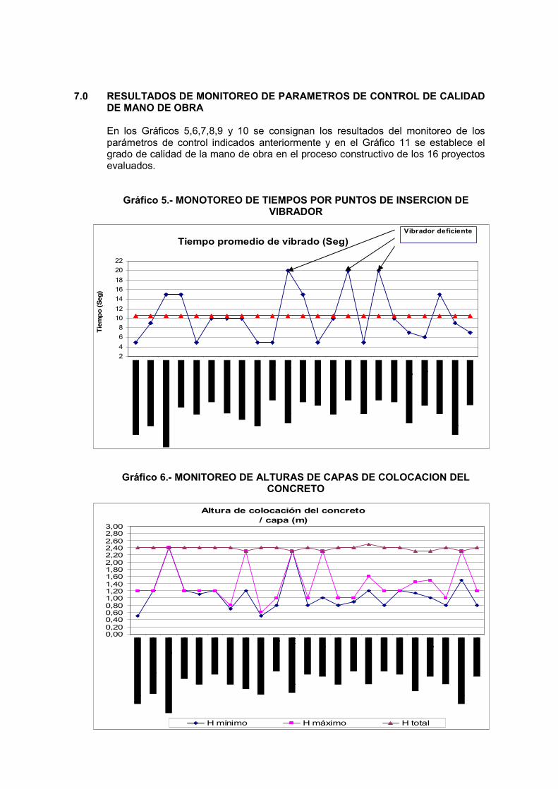
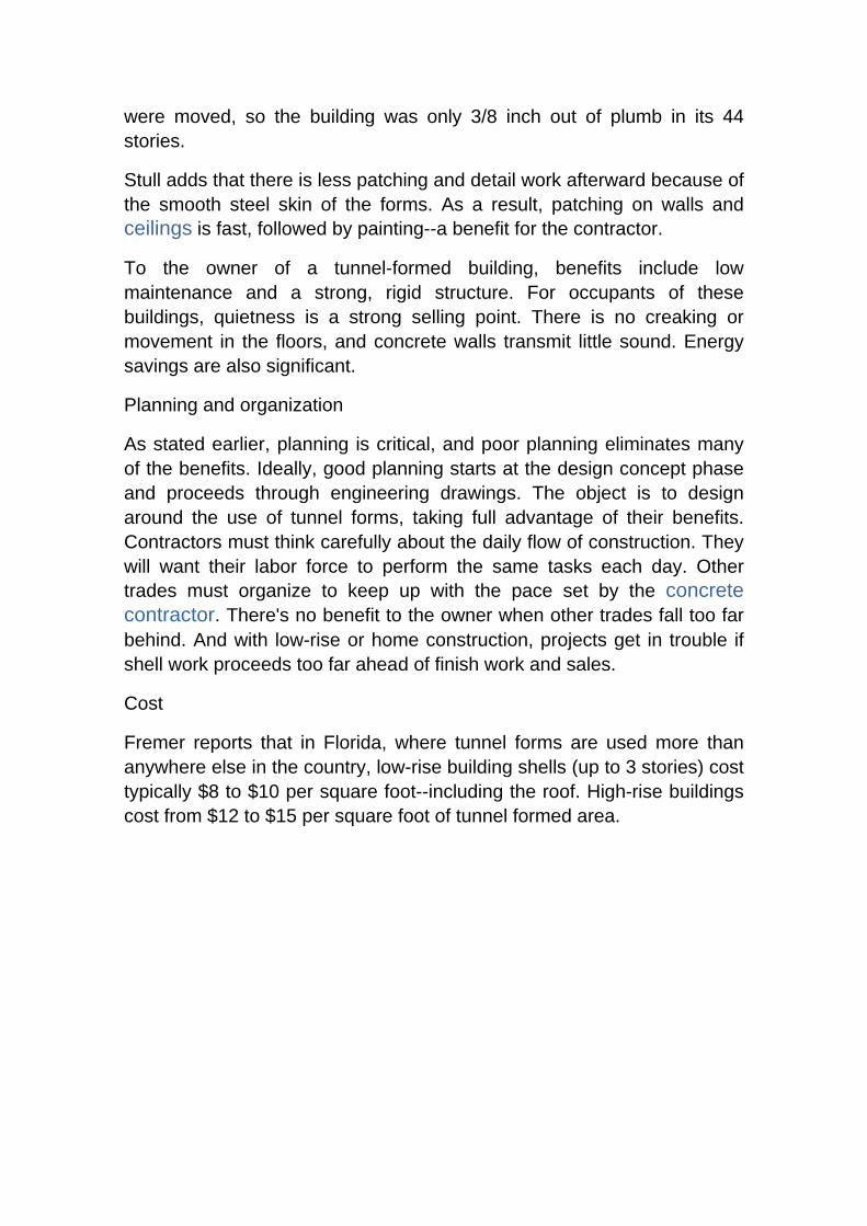
En los Gráficos 5,6,7,8,9 y 10 se consignan los resultados del monitoreo de los parámetros de control indicados anteriormente y en el Gráfico 11 se establece el grado de calidad de la mano de obra en el proceso constructivo de los 16 proyectos evaluados.
Gráfico 5.- MONOTOREO DE TIEMPOS POR PUNTOS DE INSERCION DE VIBRADOR
Gráfico 6.- MONITOREO DE ALTURAS DE CAPAS DE COLOCACION DEL
CONCRETO
Tiempo promedio de vibrado (Seg)
2
4
6
8
10
12
14
16
18
20
22
Tie
mpo (Seg)
Vibrador deficiente
Altura de colocación del concreto / capa (m)
0,000,200,400,600,801,001,201,401,601,802,002,202,402,602,803,00
H mínimo H máximo H total

Gráfico 7.- MONITOREO DE DISTANCIA ENTRE PUNTOS DE INSERCION DE VIBRADOR
Gráfico 8.- MONITOREO DE POSICION DE LA MANGUERA DE LA BOMBA DURANTE LA COLOCACION DEL CONCRETO
Distancia promedio de vibrado (m)
0,00
0,10
0,20
0,30
0,40
0,50
0,60
0,70
0,80
0,90
D mínimo D máximo
POSICION DE MANGUERA DE LA BOMBA
73%
9%
18%
Vertical
Horizontal
Alabeada

Gráfico 9.- MONITOREO DE VIBRADO EXTERNO CON MARTILLO DE GOMA
Gráfico 10.- MONITOREO DE LA HERMETICIDAD DE LA FORMALETA
EMPLEO DE MARTILLO PARA GOLPEADO DE ENCOFRADO 17%
83%
Si
No
HERMETICIDAD DEL ENCOFRADO
57%
43%
Buena
Mala

Gráfico 11.- CALIFICACION DE LA MANO DE OBRA EN BASE A EVALUACION DE PARAMETROS DEL PROCESO CONSTRUCTIVO
8.0 OBSERVACIONES Y CONCLUSIONES
1) En relación al proceso constructivo evaluado, el 52.2% se considera deficiente y el 8% crítico, no aplicándose en general las recomendaciones de los comités ACI 304.R y ACI 309.R.
2) El 21.7% del proceso constructivo evaluado se considera como regular y el 17.4%
bueno, es decir un 39.1% se considera en un rango aceptable.
3) En cuanto a la altura de colocación del concreto por capas, las mismas fluctuaron entre 0.50 y 2.40m, es decir entre 1 capa y 4 capas tendiéndose a hacerlo al menos en dos capas..
4) Se ha evidenciado en el 82.6% de los seguimientos efectuados, que el cliente no
emplea martillo de goma para el vibrado externo de la formaleta y posterior eliminación de las burbujas de aire atrapadas en las caras del molde.
5) Para el 72.7% de los seguimientos, la manguera de la bomba operaba en posición
vertical durante la descarga del concreto, incrementando considerablemente la altura de caída del concreto y la segregación.
6) Respecto a la aparición de hormigueros en los muros, el 52% se encuentra en el rango de calificación bueno, es decir no representa un problema para el constructor, el 18% está en el rango excelente y existe un 26% calificado como regular.
Evaluación del Proceso Constructivo
0.0% 17.4%
21.7%
52.2%
8.7%Muy bueno
Bueno
Regular
Malo
Muy malo

7) El 65.6% de las cangrejeras identificadas, se encuentran ubicadas en la base de los muros. Este patrón obedece a las técnicas de trabajo deficientes verificadas in-situ, como adición de agua al encofrado originando un empozamiento en el fondo y lavado posterior del concreto al ser colocado, colocación de la 1era capa de concreto en altura mayor a 0.50m y descarga del concreto con la manguera en posición vertical, entre otros.
8) Respecto al % de burbujas existentes, el 78.9% se encuentra en un rango de
calificación bueno. Asimismo, se ha encontrado que en el 87% de los seguimientos realizados, las burbujas se encuentran dispersas en todo el paño del muro en diámetros que fluctúan entre 2mm. a 10mm.
9) Más del 50% de la mano de obra evaluada es deficiente en nuestro medio en
relación con el correcto desarrollo de los parámetros influyentes en el proceso constructivo, por lo que es recomendable la capacitación continua del personal a fin de minimizar este efecto.
10) De los resultados obtenidos en las mediciones de los defectos superficiales principales (burbujas y hormigueros) y de la calificación realizada, se concluye en que pese a las deficiencia indicadas, los niveles de imperfecciones se encuentran en rangos aceptables.
11) Existe un sobredimensionamiento de la magnitud de los defectos en los acabados en nuestro medio, debido a la carencia de una metodología objetiva de evaluación, lo que lleva a reclamos y costos de resane innecesarios, sin embargo, el estudio realizado, revela que los constructores subestiman la importancia de los parámetros influyentes en el proceso constructivo y su trascendencia en los acabados, por lo que se recomienda la propuesta de estándar de referencia planteada en el presente estudio como un punto de partida de calificación inicial y posterior monitoreo de mejoras.
8. REFERENCIAS BIBLIOGRAFICAS
� Comité ACI 309.2R-98 “Identification and control of visible effects of consolidation on formed concrete surfaces”.
� Comité ACI 309.R-96 Guide for consolidation of concrete
-----00000-----
(*) Ingeniero Civil, Gerente de Investigación y Desarrollo de Unión de Concreteras S.A., Profesor de la Pontificia Universidad Católica del Perú, Profesor de la Universidad Peruana de Ciencias Aplicadas, Fellow American Concrete Institute, Past Presidente del ACI-PERU, Director Ejecutivo del Centro de Investigación Tecnológica del Cemento y el Concreto – CITEDEC, Lima,Perú.
(**) Ingeniero Civil, Jefe de Control de Calidad de Unión de Concreteras S.A.

Building with tunnel forms: of the many benefits of tunnel forms, speed is paramount. By Nasvik, Joe Publication: Concrete Construction Date: Wednesday, October 1 2003
You are viewing page 1 Consider "The Paramount at Buckhead in Atlanta." At 44 stories, it's the tallest residential structure ever constructed using tunnel forms and is the third tunnel form project for the building's owner, The Hanover Company, Houston, which required that tunnel forms be used.
Total Concrete Structures, Atlanta, the turn-key structural contractor for the project, leased enough tunnel forms to cover one-third of the floor area. The project has a footprint of approximately 13,500 square feet. "Our crews started removing forms each day at 7:00 a.m. and placed them at their next location," says Total Concrete Structures president John Stull. "At 3:00 p.m. each day, we placed concrete to complete one-third of a floor. We completed one floor every 3 days. In our contract, the schedule for the completion of the shell called for 10 months (212 working days), but we actually completed it in 9 months--30 days early." At the Buckhead site, it took only 5 minutes for a small crew to remove both half-tunnel forms from the previous day's placement and set them up at their next location. As the project manager for Hill Construction, San Juan, Puerto Rico, Rolando Maynulet builds above-grade concrete homes ranging from low cost to $500,000 custom builds. The company builds single-family residences, hotels, and "walk ups"--4- or 5-story buildings with two living units per floor. "We use tunnel forms for 85% of our work," he says. "They allow us to easily perform contracts that require the completion of one home per day. And currently we are servicing a contract requiring two homes per day." Hill also uses special steel forms to install some pitched concrete roofs.
How it all started
Tunnel forms came about as the result of a need for affordable housing dating back to the years following World War II. Demand for affordable single family residences and apartments caused Guy Blonde, technical director for Outinord, a small start-up manufacturer based in France, to come up with the idea of tunnel forms in the early 1950s. The system saved money and reduced the time to build structures because workers formed both walls and decks in one operation.

With today's refinements, tunnel forming systems are ideal for projects that offer repetitive forming opportunities--the more repetitive steps there are, the greater the benefits. These systems are ideally suited for the construction of multi-unit housing, single-family residences, hotels, townhouses, military housing, prisons, and some warehouse applications.
The blessing (and the curse) is in the details and the planning required to take full advantage of the system. With the opportunity to strip and set forms and to place concrete each and every day, shell contractors can easily produce more than other trades can keep up with--a situation that compromises the benefits to owners
How the system works
The one absolute requirement for tunnel forming is an opening on the perimeter of the structure, allowing for the removal of the form. Workers must be able to roll the forms out of the structure far enough to be handled by crane.
Bill Fremer, vice president of sales at Outinord Universal, North Miami Beach, says he looks for projects with the most repetitive work and then meets with the building's engineers to streamline the use of the forms. Outinord has continuous involvement from the very beginning stages of design.
Each half of a tunnel form looks like an upside down "L." The wall portion of the form is typically 8 to 10 feet high. According to Fremer, decks can be any width an engineer can design. Each form has wheels built in and a screw jack to adjust the elevation of the form. The two halves of the form are locked together with a special "roof lock" that also maintains flatness tolerances between the forms to within a few thousandths of an inch.
A critical piece of hardware on a tunnel form is an adjustable diagonal support, extending from the wall to the deck form. It transfers the weight of the deck to the wall form, and ultimately to the wall below the floor slab. Before a project begins, these supports are adjusted and cambered to account for the weight of the concrete on the deck. They must not be adjusted again for the duration of the project.
The process
After the first ground level floor slab is placed, workers cast a 3 1/2-inch high curb wherever a wall is to be located. Reinforcement for a wall extends through the top of the curb, tying into the floor (reinforcement for

walls is placed before curbs are cast and before the forms are put in position). The tunnel forms are then set 2 inches above the floor, against the curbs.
Next, workers attach steel blockouts to one form wall for doorways, mechanical, plumbing, and electrical vertical chases. The doors have cam levers to collapse the bulkheads for easy removal afterwards. Tapered ties with both internal and external spacers join the tunnels together. Tie spacing is typically on 4x6-foot grids.
Reinforcement for the deck above is placed after the tunnel forms are positioned. Rough electrical and blockouts for plumbing are the final steps.
After placing concrete, some contractors put tarps over the end opening of the tunnel and supply heat to the enclosure to accelerate strength gain in the concrete. Others increase the design strength of their concrete in order to achieve the 60% of design strength (typically 1200 to 1400 psi) needed to remove forms the morning after placement.
To remove the tunnel forms, workers lower the screw jacks so the wheels on the forms contact the floor. Each half tunnel form is rolled out the opening one-third its length, exposing a "lifting hole" located in the top of the form. A crane then lifts the form and moves it to the next location. As the forms are being moved out of the previous placement, workers spray form oil on the wall sections to ready them for the next cycle.
Values and benefits
Speed of construction with a small crew is the most marketed benefit; cost is generally the next most promoted value of the system. When a project can use tunnel forms, the total cost for the shell will almost always be less than with other forming systems.
Another major benefit, according to Fremer, relates to the repetitive nature of the work. There are fewer mistakes. "When a building is designed to use tunnel forms, the goal is for the same crew to perform the same steps each day. When every cycle has the same steps, there is less chance for error. For example, if blockouts for doors are in the same location on a form, holes in the form to secure blockouts are drilled once. The blockouts are always plumb and square, and workers don't have to check or adjust them each time." On the Paramount project, Stull reports that workers could easily locate the tunnel forms precisely each time they
were moved, so the building was only 3/8 inch out of plumb in its 44 stories.
Stull adds that there is less patching and detail work afterward because of the smooth steel skin of the forms. As a result, patching on walls and ceilings is fast, followed by painting--a benefit for the contractor.
To the owner of a tunnel-formed building, benefits include low maintenance and a strong, rigid structure. For occupants of these buildings, quietness is a strong selling point. There is no creaking or movement in the floors, and concrete walls transmit little sound. Energy savings are also significant.
Planning and organization
As stated earlier, planning is critical, and poor planning eliminates many of the benefits. Ideally, good planning starts at the design concept phase and proceeds through engineering drawings. The object is to design around the use of tunnel forms, taking full advantage of their benefits. Contractors must think carefully about the daily flow of construction. They will want their labor force to perform the same tasks each day. Other trades must organize to keep up with the pace set by the concrete contractor. There's no benefit to the owner when other trades fall too far behind. And with low-rise or home construction, projects get in trouble if shell work proceeds too far ahead of finish work and sales.
Cost
Fremer reports that in Florida, where tunnel forms are used more than anywhere else in the country, low-rise building shells (up to 3 stories) cost typically $8 to $10 per square foot--including the roof. High-rise buildings cost from $12 to $15 per square foot of tunnel formed area.

1
smAll hEAdlinEHighPerformanceBuildings
USING TUNNEL FORM CONCRETE CONSTRUCTION
2
Photo captions to go here
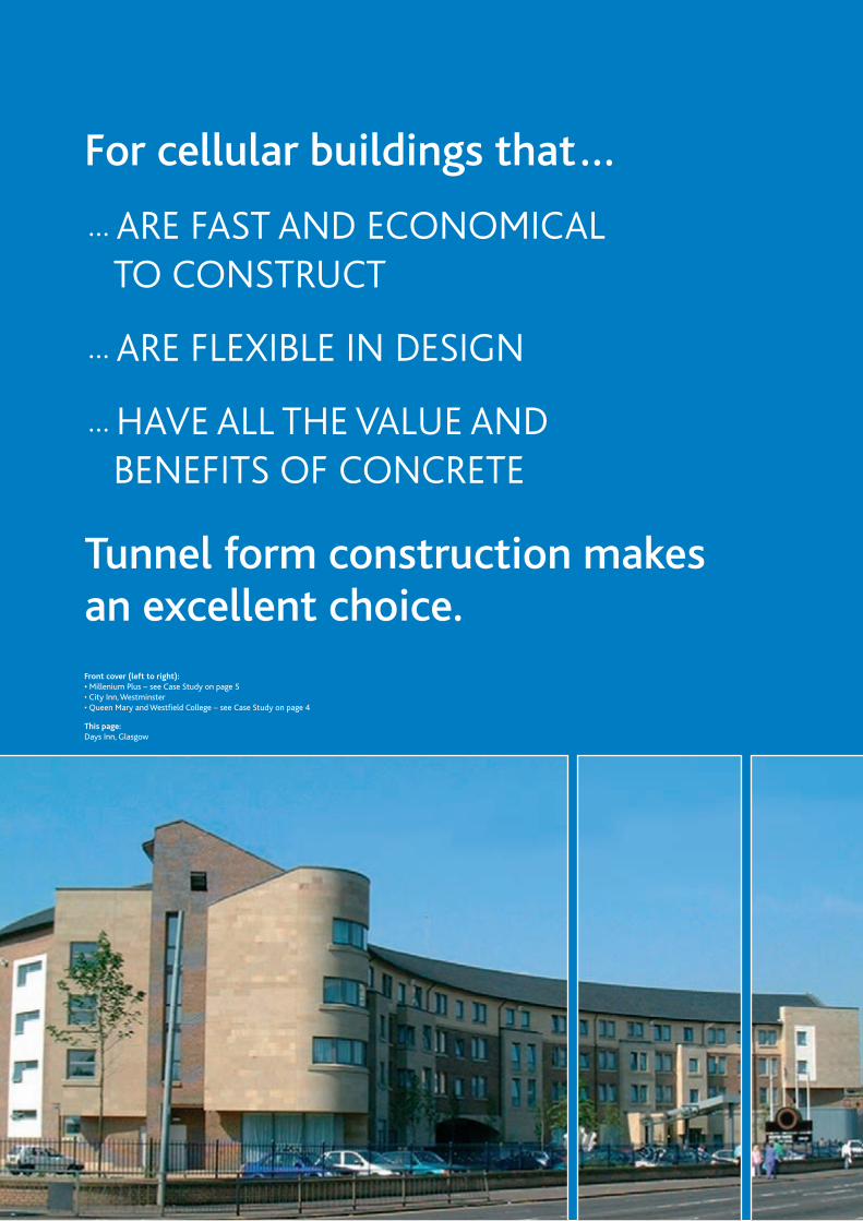
For cellular buildings that…
… ARE FAst And EconomicAl to constRuct
… ARE FlExiblE in dEsign
… hAvE All thE vAluE And bEnEFits oF concREtE
Front cover (left to right): •���Millenium Plus – see Case Study on page 5• City Inn, Westminster • Queen Mary and Westfield College – see Case Study on page 4
This page: Days Inn, Glasgow
Tunnel form construction makes an excellent choice.

WhAt is tunnEl FoRm constRuction?Tunnel form is a formwork system that allows the contractor to cast walls and slabs in one operation on a daily cycle. It combines the speed, quality and accuracy of factory/off-site production with the flexibility and economy of in-situ construction and is recognised as a Modern Method of Construction (MMC).
The result is a cellular reinforced concrete structure, the surfaces of which are of sufficiently high quality to
require only minimal finishing for direct decoration, while the end walls and façades are easily completed with
thermally insulated units that can be clad as required.
The system creates an efficient load-bearing structure for use in a wide variety of applications. It is particularly
effective in projects suited to repetitive cellular construction such as residential blocks, hotels, student
accommodation, barracks and prisons. The solid, strong monolithic structure can be 40 or more storeys in
height and the accuracy of the system suits the installation of prefabricated elements such as cladding panels
and bathroom pods, offering further MMC options. In Europe, tunnel form construction is competitive for
much smaller projects such as blocks of six apartments but is yet to be used on that scale in the UK.
The steel tunnel forms create spaces spanning 2.4 to 6.6 m. These can easily be subdivided to create
smaller rooms. Where longer spans (up to 11 m) are required the tunnel form is extended using a
mid-span section.
24HOUR CYCLE
MorningWhen the engineer gives permission, the
tunnels are struck, manually pushed onto the
dismantling platform, picked up by the crane,
scraped, oiled and repositioned. Meanwhile,
reinforcement fixing is well underway with
cast ins or inserts and stop ends installed.
LunchtimeBy lunchtime, everything is in position for pouring the concrete.
StartThe engineer completes
a concrete test to make
sure that the previous
day’s pour has achieved
the required strength. At
the same time the site
team removes the heaters,
ties, stop ends and other
non-structural works.
AfternoonConcrete pouring commences
– this can take between two
and three hours.
OvernightAfter the pour finishes, the
curtains are closed and the
heaters fired up if required.
Overnight curing starts.
1

thE bEnEFits oF using tunnEl FoRm constRuction
The UK is rapidly adopting the tunnel form system for hotel and student accommodation
and social housing. The UK construction industry has been alerted by Egan and Latham to
adopt modern methods of construction. The building process can be completed efficiently,
economically and faster with benefits for everyone concerned.
The tunnel form system exploits these principles to provide cost-effective, high quality
construction, generating significant savings in time and costs over alternative methods
without compromising on design. Tunnel form projects have proved that impressive results
can be achieved in productivity, efficiency, economy and quality. The system is now one
of the most preferred methods of cellular construction with architects, engineers and
contractors throughout the world, whilst clients appreciate tunnel form’s ability to deliver
projects to budget and on time.
Costs
Value engineering starts with the early involvement of the formwork supplier. The formwork
is available to the contractor for purchase or rent and can be reused on other projects.
Not only does tunnel form often reduce the cost of the frame by over 15%, its application
provides construction efficiencies resulting in an average savings of 25% in the time taken
to complete the frame. The resulting monolithic construction can also produce savings in the
foundations.
Productivity and control
The formwork is specially adapted for each project. The repetitive nature of the system and
the use of prefabricated forms and reinforcing mats/cages simplifies the whole construction
process, producing a smooth and fast operation. The techniques used are already familiar
to the industry, but with tunnel form construction there is less reliance on skilled labour.
On average, a team of nine site operatives plus a crane driver can strike and fix 300 m2 of
formwork each day, including placing approximately 35 m3 of ready-mixed concrete. The
work can continue in all weather except high winds, and heaters can be used to accelerate
the concrete curing process.
The schedule provided by the 24-hour cycle means each operative knows exactly what to do
and when, and works to a precisely detailed plan. The smaller work teams and predictable,
measurable daily production rates simplify and enhance overall control of the project.
Known completion times make scheduling of material deliveries and follow-on trades more
accurate and optimise cash flow by facilitating ‘just in time’ principles. By quickly providing
protection, the system allows the following trades to commence work on completed rooms
while work proceeds on upper floors.
Quality
Quality is enhanced despite the speed of construction. The precise, even steel face of the
formwork creates a smooth, high quality finish capable of receiving direct decoration with
the minimum of preparation (a skim coat may be required). This reduces the requirement for
finishing trades, thus providing additional cost savings and speeding the entire process.
Design
The large bays constructed using tunnel form provide exceptional flexibility in the design
and layout of the building and allow a high degree of freedom in the final appearance. The
elevations can be adapted by using extendable formwork to create cantilevered balconies
and the exterior can be finished in any way the architect requires, from brick slips on highly
insulated framed infill panels, to sophisticated curtain walling systems.
tunnel form construction can provide:• Substantial savings
in costs
• Substantial savings in labour
• Much faster construction
• Enhanced safety
• Better management control
• Predictable work flow
• Quicker return on investment
• Precise, high quality structures
• Design flexibility
• …and all the added value of concrete
Diagram showing the typical two-day progress of construction
2

The high levels of dimensional accuracy achieved with
tunnel form and the superior load distribution result
in a strong, solid monolithic structure suitable for a
multitude of uses. The ability to create clear spans up
to 11 m wide provides the opportunity to use non load-
bearing internal partitions that can be moved to provide
alternative layouts.
Safety
Tunnel form has integral working platforms and
edge protection systems. In addition, the repetitive,
predictable nature of the tasks involved encourages
familiarity with operations and, once training is
complete, productivity improves as construction
progresses. The minimal requirement for tools and
equipment when moving the tunnel form further
reduces the risk of accidents on site.
Comprehensive method statements from the
formwork suppliers and a full safety risk assessment
enhance safety in tunnel form’s application. The
system meets all the current Health & Safety
construction site requirements. In addition, for the
client and end user, the superior fire resistance and
strength inherent in concrete structures increases
confidence in the building itself.
Environment
In today’s environmentally conscious society, we
are under ever-increasing pressure to reduce waste
and provide energy efficient buildings within
sustainable communities. Tunnel form provides
benefits in key areas:
• The in-situ casting of units on site and the local
availability of ready-mixed concrete supplies
reduce transportation impacts.
• Just–in-time deliveries and near zero wastage
produce an overall tidier site with associated
cost savings and safety benefits plus minimum
disruption where the site is already partly occupied.
• Concrete’s thermal mass coupled with correct
insulation and boiler design minimises heating costs
and can even reduce air-conditioning requirements,
with the resultant benefits for the environment.
The monolithic and accurate structure facilitates
airtight construction – an expected requirement in
the 2005 amendment to the Building Regulations,
Part L.
• Direct finishes and durable walls minimise
decoration, repair and refurbishment costs.
Wallpaper can be directly applied or a skim coat
may be used to provide a perfect plastered finish.
• In combination with the correct flooring and ceiling
systems for separating floors, tunnel form floors
can use the Part E Robust Detail No. E-FC-2 and be
confident of passing the pre-completion testing
(PCT) required for Part E sound insulation. With
tunnel form, party walls are simple and can be
made of the concrete itself or be non load-bearing
demountable partitions of lightweight concrete block
work, or plasterboard systems. All of these require
PCT with a range of suggested options in the Part E
document or from the acoustic specialist, which
should satisfy the new requirements.
Ease of service installation
Service runs can be pre-installed before the concrete
is poured. Other facilities such as bathroom pods
can be installed as completed units using existing
access platforms.
Modern Methods of Construction (MMC)
The use of tunnel forms brings factory quality and
efficiency to site and so is recognised as a Modern
Method of Construction under the initiative being
promoted by the ODPM. Referenced in Housing
Corporation documentation, it is eligible for use by
Housing Associations as an MMC system.
Support
The tunnel form suppliers/contractors provide full design
and technical support to ensure engineers, architects
and site staff are all familiar with the system and its
application as the project starts, enabling time and cost
savings to be achieved. If the site staff is inexperienced
with tunnel form construction, the supplier’s site training
quickly brings them up to speed.
The new tunnel form block of student accommodation
at the University of East Anglia was acoustically tested
in August 2004 with excellent results.
Although not domestic residences, university halls,
hotels and hostels all have to comply with the new
Building Regulations Sound requirements of Part E
2003. They will not be permitted to use the Robust
Detail route and will have to undergo pre-completion
testing (PCT). As a monolithic structure, tunnel form
is one of the few systems that should be totally
repeatable and therefore can be used with confidence
on future projects using the same construction details.
Two separating floors in the new block, consisting of
250 mm of concrete with a stuck-down carpet and no
ceiling finish beneath, were tested. They both exceeded
the regulations by more than 5 dB for both
airborne and impact sound insulation (actually
meeting the levels required by Robust Details).
Had a floating floor and suspended ceiling been
incorporated the results would have been
even better.
Two separating walls were also tested,
each comprising 180 mm concrete with a
2 mm plaster skim finish. Both met the PCT
requirement and could have exceeded it
further with the addition of wall linings.
This test, no 040901, carried out by an
independent acoustic expert, is downloadable
from the Residential section of The Concrete
Centre website www.concretecentre.com.
AcouStic tESt rEPort
3

studEnt AccommodAtion FEAtuRing thE uK’s lARgEst tunnEl FoRm schEmE
Project description
The concrete shells for this village of six blocks for Queen Mary and Westfield
College, University of London, varying in height from four to eight storeys, were
constructed to a fast-build programme within 26 weeks. The finished buildings
contain apartments with bedrooms and dining room/kitchens, offering a range of
accommodation for 1000 students.
Why tunnel form was chosen
The repetitive nature of student housing lent itself to a factory-on-site production
system, exemplified by tunnel form. The design-and-build contract allowed the team
to optimise construction processes. Ten different construction options were considered
for economy and speed by structural engineer, Adams Kara Taylor, before tunnel form
was chosen. Cost, as always, was a key driver in this project. Fire and sound resistance
were also deciding factors in favour of concrete. After looking at its use in some recent
projects, contractor Laing O’Rourke concurred with the design team’s choice of tunnel
form and was confident enough to purchase the specialist formwork system and reuse
it on a later project at Holloway College.
Construction
The construction was planned around the tunnel form 24-hour cycle, using two sets
of tunnels, each producing two bays, as its requirements would drive the programme.
The dimensionally accurate and modular nature of the system led to the choice of
bathroom pods, which eliminated repetitive trade fixing. Two bays, typically 6.3 m
wide by 10.3 m deep, were constructed in each cycle. After subdivision each produced
six study-bedrooms and a dining room/kitchen. The contractor’s teams were able
to master the system within one week, producing the high quality finishes required.
Cladding and internal panels were prefabricated or pre-cut. This was made possible by
the tight dimensional control of the system, saving time and money and eliminating
waste. Where possible, services were run in these panels and trunking to minimise
buried ducts in the concrete. Good planning and management are an integral part of
the system, and on this project three cranes were used to ensure timely movement of
materials and formwork.
Special interest
The superstructure - frame, floor slab and internal walls - for a 175-bedroom block was
built in only 32 days. Throughout the contract waste ready-mixed concrete amounted
to only 0.15% of the total delivered.
What tunnel form brought to the project
Tunnel form brought a factory production line to site, and the resulting dimensional
accuracy, quality finishes and predictable fast output encouraged prefabrication and
forward planning of processes and materials delivery. This extended to the contractor
fitting out the bedrooms, complete with beds, in addition to the bathroom pods.
Students and the client will reap the benefits of concrete construction, including
good acoustic performance, excellent fire resistance, high thermal mass and low
maintenance, all achieved within budget.
cAsE studiEsthree different projects spanning the student, hotel and housing markets demonstrate the versatility of tunnel form construction in delivering quality and speed.
Queen Mary and Westfield College: cells complete for following trades to commence.
“ ” “ The tunnel form system is amazing… things just seem to appear out of nowhere.”
Ken Kinsella, client project manager, Queen Mary and Westfield College.
“A superb system; the way the industry will move forward…”
Gordon Latimer, Laing O’Rourke’s project manager.
4

A nEW FivE-stAR hotEl bEhind histoRic FAçAdE
Shared ownership flats at the Millennium project, showing the bay windows achieved by modifying the formwork.Photo: Southern Housing Group
Project description
Millennium Plus at the Nightingale Estate, Hackney, is a multi million pound regeneration project, comprising several hundred new houses and flats for rent, shared ownership and open market sale. The Southern Housing Group worked in partnership with the Council, designers Watkins Gray International, Philip Pank Partnership cost consultants and Countryside in Partnership. The first new homes were completed in 2001, with the entire regeneration project due to finish in 2008. This Housing Forum Demonstration Project harnesses resident involvement in design, innovative construction, partnering and the early involvement of contractors to improve efficiency
and space standards and reduce costs in use.
Why tunnel form was chosen
Formwork has significant effect on a project’s economics and construction speed, so tunnel form was used for the in-situ concrete structure to achieve a fast construction programme with thermal mass, high sound insulation properties and inherent fire resistance. The system effectively brought a factory production line to site, with its accuracy, speed and quality allowing prefabricated insulated frame wall panels for the front and rear elevations. An open loft space is provided by the concrete spine walls covered by a factory-made roof panel that was craned into position. These innovations aimed to reduce the
construction period by six weeks.
Construction
Concrete piled foundations and ground beams support the reinforced concrete tunnels that form the structure from ground floor level to the ridge of the roof with 200 to 230 mm thick walls, and floors between 175 and 250 mm thick. The structure is cast one floor at a time in situ, using long life factory-made steel tunnel formwork designed to suit a variety of dwelling module sizes. The process produces a complete building structure of floors and party walls from ground level to ridge level. The structure is then
ready to be enclosed with a highly insulated envelope.
What tunnel form brought to the project
Tunnel form and in-situ concrete have contributed
significantly in providing:
• Strong and durable walls, with high acoustic
performance.
• Innovative, spacious and user friendly design, with
large open plan lofts.
• Good site productivity - the predictable daily cycle
allows efficient material supplies and use of follow-
on trades with cast-in services.
• High quality finishes, enabling exposed concrete surfaces
for high thermal mass and airtight construction, helping
to achieve heating and hot water costs of around £3 per
week for a large three-bedroom house.
Project description
The Radisson Edwardian Hotel, Manchester, a
268-room, five-star hotel, has been built behind the
listed building façade of the Free Trade Hall, a land-
mark Victorian building in the heart of Manchester.
There are two blocks connected by a glass atrium,
which provide function and public rooms. Behind the
façade, and replacing an uninspiring 1950’s structure,
is a new 16-storey tower built using the tunnel form
system.
Why tunnel form was chosen
Approvals for this sensitive site took more than seven
years, with Arup providing structural, geotechnical,
acoustic and M&E services. The consortium of Alfred
McAlpine Special Projects and Laing O’Rourke chose
tunnel form for the bedroom block as its cellular form
and operation suited this congested city centre site.
Speed of construction and cost, plus the fire, acoustic and
thermal mass properties of the tunnel form concrete’s
225 mm slab and 200 mm walls sealed the deal.
Construction
Four rooms were cast each day, six days a week.
One team carried out the formwork, reinforcement and
concreting activities. The 24 hour cycle required high
early strength for striking – 15 kN was typically achieved
by early morning (see 24-hour cycle on page 1).
The concrete mix was tailored to suit the needs of
pumping to a height of 15-storeys, in addition to those
for early strength, good workability and finishes, and the
growing summer heat.
What tunnel form brought to the project
A five-star hotel needs to be seen as superior, and
tunnel form concrete met the high demands for
building performance and quality, such as excellent
acoustic performance of walls and floors. At the
same time, it matched the consortium’s needs for
construction speed, value, and operational flexibility
within this difficult and historic site.
MAJor LonDon rEgEnErAtion ProJEct
“ ” “ The residents appreciate the useful clear loft space, floors which don’t squeak, and they really like the look of the new homes. Thermal and sound insulation is good, too.” Jill Beaver, client project manager, Southern Housing Group.
The new tunnel form Radisson Hotel behind its historic façade.
5

CPD presentations on concrete and tunnel form construction are available on request. Please call 0845 812 0000 or email [email protected]
Ref. TCC/04/02
ISBN 1-904818-12-9
First published 2004
© The Concrete Centre 2004
The Concrete Centre, Riverside House,
4 Meadows Business Park, Station Approach, Blackwater, Camberley, Surrey GU17 9AB
National Helpline 0845 812 0000
Advice and visual material supplied by Ischebeck Titan and Southern Housing.
All advice or information from The Concrete Centre is intended for those who will evaluate the significance and limitations of its contents and take responsibility for its use and application. No liability (including that for negligence) for any loss resulting from such advice or information is accepted. Readers should note that all Centre publications are subjectto revision from time to time and should therefore ensure that they are in possession of the latest version.
www.concretecentre.com
Chelsea Village Hotel, London.
CI/SfB
UDC
69.057.52:728.569.057.52:728.5

An ocean view from all 400guest rooms at the Sh e ra-ton Grande Torrey Pines inLa Jolla, Ca l i f o rnia, is but
one of many amenities at the new$60-million luxury hotel. The archi-tect provided eve ryone an oceanview by designing a 30° bend in thesidewalls of the ro o m s. The builderexecuted it in concrete with the useof a unique, modular room formingsystem. The substantial concre t ec o n s t ruction—walls 8 inches thickand 5 1⁄2-inch-thick slabs—bri n g sthe guests added benefits of firesafety and noise resistance at thiselegant hostelry. The guest ro o m sa re divided among four 4-storyf reestanding wings, oriented atright angles to a golf course and theocean. In t roducing the 30-degre ebend in each room turned its pic-
t u re window tow a rd the ocean in-stead of looking across at anotherhotel room.
The modular forming system
The contra c t o r, Hensel Ph e l p sCo n s t ruction Co m p a n y, decided touse the so-called tunnel form i n gsystem to meet the compre s s e dtime schedule for the guara n t e e d -m a x i m u m - p rice construction of thehotel complex. With tunnel form i n gs y s t e m s, ro o m - s i ze or larger mod-ules of form w o rk are lifted intoplace by crane for the casting ofb e a ring walls and slab in a singlep o u r. At To r rey Pines, the tunnelf o rm for each room was split ve rt i-cally down the center of the 13.5-foot room width to accommodatethe skews in the guest room walls.Each form half was re m oved, flow n
by the cra n e, and set separa t e l y.Hensel Phelps developed a sched-
ule that allowed four guest rooms tobe cast at one time, two on each sideof the hallway, which was shaped bya modified box culve rt form (seephoto). Rather than casting two fullrooms adjacent to each other, thec o n s t ruction module consisted ofone complete room box on eachside of the corri d o r, flanked by twohalf ro o m s. When the tunnel form swe re stripped and reset, the halftunnel butted against the pre v i o u s l ycast half, completing the ro o m .
The architect made only twochanges in the original room designto accommodate the modularf o rm s. An upturned concrete beamto support a balcony hand rail wasdeleted, and a second upturn e dbeam in the deck further back in the
Fast-tracked concrete hotel
Tunnel forming system speeds room construction
BY M. K. HURD
ENGINEERING EDITOR
Half tunnel form, enough for walls anddeck of half a hotel room, lifted bycrane to its position on one wing of the400-room hotel (left). Closer view(above) shows the 30° bend designedinto each room module.

room was eliminated through ad-dition of extra re i n f o rcement inthe slab.
Fast-track scheduling
“Co n s t ruction was scheduleda round the fast-track nature of thej o b,” according to Ma rv i nSchmidt, general superi n t e n d e n tfor contractor Hensel Ph e l p s.“Even as late as December 1988,p o rtions of the facility—such as ap a rking garage— we re still beingdesigned just weeks ahead of con-s t ru c t i o n .” Schmidt says theychose a tunnel form system basedon experience with this type off o rm on seve ral other hotel jobsw h e re they we re able to pro c e e dabout twice as fast as with conve n-tional deck and ganged wall form s.The La Jolla job differed from theo t h e r s, howe ve r, in that this wasthe first time they had used a tun-nel forming system made in theUnited St a t e s.
A single pour of the equiva l e n tof four rooms eve ry 24 hoursp roved to be the best way for
Hensel Phelps to use the system.Fo rming fewer rooms would noth a ve taken full advantage of thes y s t e m’s capabilities, and buildingm o re, according to Schmidt,might have been inefficient be-cause of crane time and the possi-bility of trades getting in each oth-e r’s way trying to maintain thec yc l e. The first few cyc l e s, howe v-e r, took much longer than 24hours while the crews we re learn-ing how to handle all the va ri o u ss t e p s — s t ripping, flying the form s,resetting, installing rebar andb l o c k o u t s, and pouring—all inone day.
Pro g ress settled down to asteady four rooms per day with ac rew of 10 carpenters, 6 labore r s,4 iro n w o rk e r s, and a 4-man finish-ing cre w. He a t e r s, heat curt a i n s,l i g h t s, hand ra i l s, and access scaf-folding attached to the form ss t a yed with the sections as theywe re flown. After the 4000-psi con-c rete was pumped into place andfinished in the slab and walls forthe four ro o m s, it was heat cure dove rnight at 150° F, to gain an ave r-age 2000-psi compre s s i ve stre n g t hb e f o re stripping the next day. Theonly conventional wall form sneeded we re for nontypical wallsat the ends of the four wings of theh o t e l .
Form features contributeto efficiency
Among the forming hard w a ref e a t u res designed for improved ef-ficiency we re cam locks that heldthe knee braces of struts support-ing deck portions of the form s.The knee braces permitted deckand wall form surfaces to bepulled down and about an inchaway from the concrete for formre m oval. Cam lever connectorswe re used to align and pull mat-ing edges of form sections togeth-e r.
Pe rmanent magnets secure dsmall blackouts used to formopenings in the deck, with a mag-net placed in each corner of ablockout. Since the magnets we res t rong enough to hold the black-
A modified box culvert form was used tomake hallways, with integral slab-and-walltunnel forms set on either side. Theculvert form was moved lengthwise downthe hall from pour to pour.
Worker placespermanent magnetsthat attach smallblockouts to thesteel deck forms.The magnets arestrong enough tohold the blockoutform in place duringconcreting, and theyeliminate drillingholes in the deck.

outs in place during the pour, noholes for conventional screw attach-ment had to be made in the deck.Simple plates that slipped into placewe re used to hold starter wall form sin position rather than connectorsor bolts.
The forms we re built heavier—18.5 pounds per square foot—andwith thicker skins than typical Eu ro-pean-made tunnel form s, to re s i s tdeflection and assure that the wallsremained straight. The extra ri g i d i t ymade the wall surfaces smoothenough for direct application ofv i n y l i zed wall cove ring. “If ourf o rming equipment wasn’t ri g i d ,”Schmidt said, “we would need tospend lots of money finishing thec o n c re t e. Also, all wall corners andjoints are sharply delineated by thef o rms to assist edging the wall cov-e ri n g s.”
Concrete contributes to the competitive edge
In a climate of increased competi-tion within the lodging industry, theI TT Sh e raton Co r p o ration has de-c l a red its commitment to quality ac-commodations that will attract re-
peat and re f e r ral business. TheSh e raton Grande To r rey Pines isbut the most recent link in an ex-panding chain. And the concre t es t ru c t u re at To r rey Pines— dura b l e, f i re resistant, and quiet—is a stro n g ,silent partner in the worthy en-d e a vo r.
Credits Owner: ITT SheratonCorporation/North America Taisei Cor-porationArchitect: Welton Beckett AssociatesStructural engineer: Erkel/Greenfield &AssociatesGeneral contractor: Hensel PhelpsConstruction Company in a limitedpartnership with Taisei North AmericaCorporation
P U B L I C AT I O N # C 9 0 0 4 6 0
Copyright © 1990, The Aberdeen Gro u p
All rights re s e r v e d

Tunnel Forms Page: 1
Tunnel Forms by Outinord Outinord is a French corporation that designed, developed, and produces a unique form system that claims to reduce labor time, improve quality, and simplify working conditions. The tunnel- form system has been in use for over 35 years on over 200,000 construction sites throughout the world. In the United States the tunnel- form system is being used successfully in residential construction by DiVosta Construction Company of West Palm Beach, Florida (recently--1999-- purchased by Pulte). System Components The main components of the system that form a structure are:
Half-tunnels are made up of a horizontal and a vertical panel that are connected by two inclined struts. The half- tunnel appears like an upside down "L". Stability is provided by a support prop that holds the horizontal (or soffit) panel up and is attached to the base of the vertical panel by two braces arranged in the form of a triangle. The support prop serves no structural purpose; it serves only to keep the half-tunnel form from tipping over when not attached to another form. Wheels incorporated in the bottom edge of the vertical panel and at the bottom of the support prop facilitate positioning of the form. Jack bolts along the base of the vertical panel allow fine adjustment for vertical alignment. The half- tunnel form is used to form one side of a wall element and the underside of the adjacent ceiling. The following schematic shows three half- tunnel elements. Bay spans for half- tunnel forms can be increased by using an infill panel or table form.
There is also a full-tunnel form (not shown in the schematic) that looks much like an upside down "U". The full-tunnel form is used for forming narrower spaces. Its function is to form the inside of two facing walls and the underside of the ceiling between.
Back Panel is attached to a half-tunnel or full-tunnel to form the inside surface of a connecting cross wall. Two back panels attached to the half-tunnel forms are shown in the schematic.
Slab and Wall Stop Ends are installed on the vertical wall panels and the horizontal slab panels to serve as the edge form of the concrete.
Box-outs are attached to the outside of the tunnel form at the places where door or window openings are to be located or on top of the horizontal panel where stairway openings are to be located.
Kicker Forms or Starter Walls are used when placing the initial slab-on-grade as well as at the top of walls when a second story is to be added. The purpose of the kicker form is to create a 3-inch high starter wall that is shaped like a rectangular curb. The starter wall or curb is used in positioning the tunnel forms.

Tunnel Forms Page: 2

Tunnel Forms Page: 3
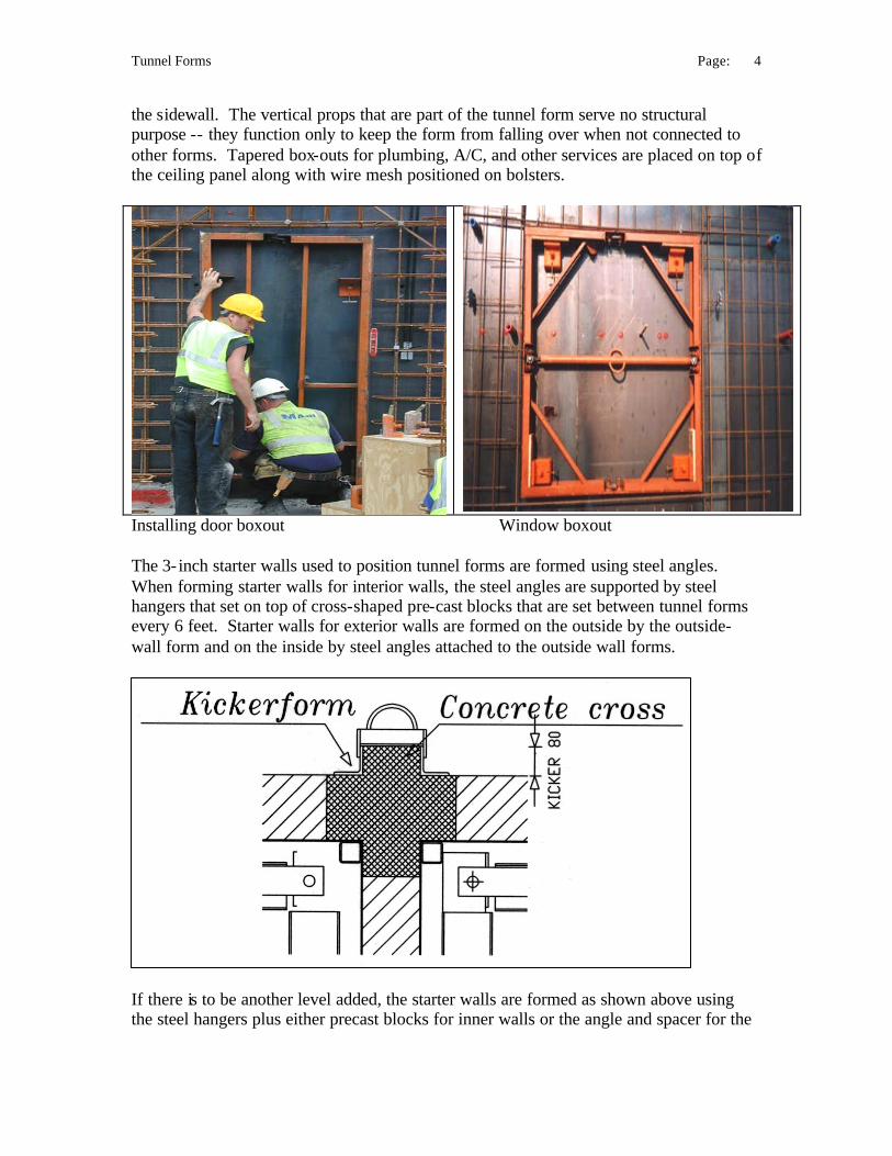
Construction Sequence The first step is to cast the slab including the 3- inch starter walls (kickers) that are used to position the tunnel forms. The starter walls must be carefully positioned and their vertical alignment must be accurate. Rebar is embedded in the starter walls 2-feet on-center.
After the starter wall forms have been stripped, room-length sheets of welded wire mesh are tied to the rebar. The rebar provides continuity of reinforcement for each floor level from the floor below. Tunnel forms are then placed by crane between the rows of reinforcement, butted against the starter walls for alignment, and leveled with the screw jacks. Electrical conduit is installed and box-outs for doors, windows, and other openings are placed in precut openings in the wire mesh. Forms for the other side of each wall (which may also be tunnel forms) are then placed. Spacers are used to center the wire mesh between the forms. The inclined struts that are an integral part of the tunnel form are adjusted to insure that the ceiling panel is positioned at the proper height. The struts transfer the load of the concrete to the base of
Tunnel Forms Page: 4
the sidewall. The vertical props that are part of the tunnel form serve no structural purpose -- they function only to keep the form from falling over when not connected to other forms. Tapered box-outs for plumbing, A/C, and other services are placed on top of the ceiling panel along with wire mesh positioned on bolsters.
Installing door boxout Window boxout The 3- inch starter walls used to position tunnel forms are formed using steel angles. When forming starter walls for interior walls, the steel angles are supported by steel hangers that set on top of cross-shaped pre-cast blocks that are set between tunnel forms every 6 feet. Starter walls for exterior walls are formed on the outside by the outside-wall form and on the inside by steel angles attached to the outside wall forms.
If there is to be another level added, the starter walls are formed as shown above using the steel hangers plus either precast blocks for inner walls or the angle and spacer for the
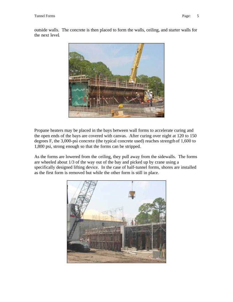
Tunnel Forms Page: 5
outside walls. The concrete is then placed to form the walls, ceiling, and starter walls for the next level.
Propane heaters may be placed in the bays between wall forms to accelerate curing and the open ends of the bays are covered with canvas. After curing over night at 120 to 150 degrees F, the 3,000-psi concrete (the typical concrete used) reaches strength of 1,600 to 1,800 psi, strong enough so that the forms can be stripped. As the forms are lowered from the ceiling, they pull away from the sidewalls. The forms are wheeled about 1/3 of the way out of the bay and picked up by crane using a specifically designed lifting device. In the case of half-tunnel forms, shores are installed as the first form is removed but while the other form is still in place.

Tunnel Forms Page: 6
Straight-run stair forms are poured on their side.
The forms, plus the heated curing, allow concrete to be placed on a daily repetitive basis. Cost, Quality, and Precision Building dimensions are reportedly held to within 1/32 of an inch. This level of precision allows plumbing elements and electrical conduit to be precut to size, leaving only installation to be done in the field. A key element in achieving this level of precision is the starter walls that serve as the guide for aligning the tunnel forms. In addition to precision, the tunnel- form system encourages quality in the construction process. That is, the nature of the system is to create a rhythm for the worker. By taking advantage of the heat-assisted drying, the same steps in construction are repeated each day in the same sequence. The workers quickly become accustomed to the pattern and identify the most efficient procedures. The result is a work force that can work effectively together as a highly productive team. New workers can be trained quickly and achieve high quality performance rapidly. The product produced is of consistent quality from day to day. The cost of tunnel forms, including the heating system and all accessories, average $40 to $45 per square foot of contact area. In order to make the forms a cost/effective option, it is necessary that be used at least 150-200 times. That is, the builder should consider producing 150-200 identical homes. The estimated life of the forms is 500 to 1,000 reuses. The forms can be rebuilt for forming different designs. The cost of the concrete shell for the construction of four-unit townhouses in Florida ranged from $4 to $5 per square foot of floor area. The forms represented $1 of this amount. The total building cost for the units was about $21 per square foot.
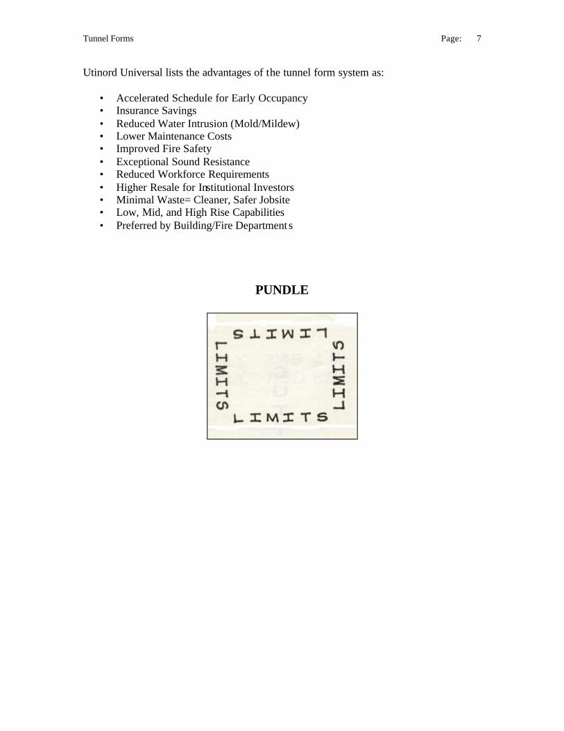
Tunnel Forms Page: 7
Utinord Universal lists the advantages of the tunnel form system as:
• Accelerated Schedule for Early Occupancy • Insurance Savings • Reduced Water Intrusion (Mold/Mildew) • Lower Maintenance Costs • Improved Fire Safety • Exceptional Sound Resistance • Reduced Workforce Requirements • Higher Resale for Institutional Investors • Minimal Waste= Cleaner, Safer Jobsite • Low, Mid, and High Rise Capabilities • Preferred by Building/Fire Department s
PUNDLE


![Libro de Concreto Estructural Reforzado y Simple Aplicando La Norma Peruana E.060 Tomo I [Ing. Basilio J. Curbelo] CivilGeeks(2)](https://static.fdocuments.ec/doc/165x107/5695d0541a28ab9b02920785/libro-de-concreto-estructural-reforzado-y-simple-aplicando-la-norma-peruana.jpg)