Journal of Mechanical Engineering Vol 16(1), 121-134, 2019 ...
14
Journal of Mechanical Engineering Vol 16(1), 121-134, 2019 ___________________ ISSN 1823- 5514, eISSN 2550-164X Received for review: 2017-05-25 © 2018 Faculty of Mechanical Engineering, Accepted for publication: 2018-12-15 Universiti Teknologi MARA (UiTM), Malaysia. Published: 2019-04-01 Stereo Vision for Visual Object Tracking and Distance Measurement Assessment Sukarnur Che Abdullah 1 , Mohamad Dzulhelmy Amari 1 and Masahiro Ohka 2 1 Faculty of Mechanical Engineering, University Technology MARA (UiTM ) ,40150, Shah Alam, Selangor, Malaysia. 2 Graduate School of Information Science, Nagoya University, Furo-cho, Chikusa-ku, Nagoya-shi, Japan. ABSTRACT The computer vision for binocular eyes system has many applications in robot applications and safety purposes. Based on the previous research, the combination of the area of sight of stereo vision will trigger the trigonometry intersection point for determine the distance of the objects from it baseline. The system programme codes is one of the issue need to confront consequent since there are various sorts of calculation that are in the same field, however has unmistakable of use. This project focuses on how to measure distances using binocular vision. The main objective is to evaluate the binocular vision system by calculating the distance of objects in real environment. Furthermore, the project proposes a new program algorithm for binocular vision system to work, in order to identify distance of an object with a basic equation has been derived and set in the designed algorithm. The setting environment are set to single and multi-objects measured, object in environment and changes of degree of bright light. Evaluation of the system shows the detected distances are consistence and the data were recorded. The value of the distances detected are then compared with the real environment distances. The result show distances measured moderate enough for proposed system to function and may facilitate improvements in computer vision system for industry.
Transcript of Journal of Mechanical Engineering Vol 16(1), 121-134, 2019 ...
Journal of Mechanical Engineering Vol 16(1), 121-134, 2019
___________________
ISSN 1823- 5514, eISSN 2550-164X Received for review: 2017-05-25
© 2018 Faculty of Mechanical Engineering, Accepted for publication: 2018-12-15
Universiti Teknologi MARA (UiTM), Malaysia. Published: 2019-04-01
Stereo Vision for Visual Object Tracking and
Distance Measurement Assessment
Sukarnur Che Abdullah1, Mohamad Dzulhelmy Amari1
and Masahiro Ohka2
1Faculty of Mechanical Engineering,
University Technology MARA (UiTM ) ,40150,
Shah Alam, Selangor, Malaysia.
2Graduate School of Information Science, Nagoya
University, Furo-cho, Chikusa-ku, Nagoya-shi, Japan.
ABSTRACT
The computer vision for binocular eyes system has many applications in robot
applications and safety purposes. Based on the previous research, the
combination of the area of sight of stereo vision will trigger the trigonometry
intersection point for determine the distance of the objects from it baseline.
The system programme codes is one of the issue need to confront consequent
since there are various sorts of calculation that are in the same field, however
has unmistakable of use. This project focuses on how to measure distances
using binocular vision. The main objective is to evaluate the binocular vision
system by calculating the distance of objects in real environment.
Furthermore, the project proposes a new program algorithm for binocular
vision system to work, in order to identify distance of an object with a basic
equation has been derived and set in the designed algorithm. The setting
environment are set to single and multi-objects measured, object in
environment and changes of degree of bright light. Evaluation of the system
shows the detected distances are consistence and the data were recorded. The
value of the distances detected are then compared with the real environment
distances. The result show distances measured moderate enough for proposed
system to function and may facilitate improvements in computer vision system
for industry.

Sukarnur Che Abdullah et al.
122
Keywords: Computer vision, binocular camera, epipolar plane, 2.5-
dimensions, distance and environment.
1 Introduction
Binocular vision alludes to the condition where the two eyes see a
typical segment of visual space. In vertebrates, the measures of this cover
extent from 0⁰ to around 190⁰ in humans. There could be a lot of things that
use binocular vision as their sight type [1-2]. Robot vision that has associated
with not calibrated environments [3] ordinarily have constrained situating and
following abilities, if control errands cannot be suitably modified utilizing
accessible elements as a part of the situations. In particular, to perform two and
half dimensions (2.5D) trajectory taking over operations using binocular
vision, it appears to be important to have need learning on point shrewd
correspondence data between two picture planes. In any case, any suspicion
cannot be made for any smooth 2.5D trajectory. This anticipates depicts how
one may upgrade self-governing robotic vision for 2.5D taking over
assignments utilizing eye-to-hand binocular visual. Taking over account of the
novel encoded blunder, a picture-based criticism control law is proposed
without expecting point shrewd binocular correspondence data that still can
measure distances of an item [4].
The proposed control of the method has been to ensure errand
accuracy by utilizing just an around to align binocular vision system. The
objective of the given undertaking is to drive an instrument mounted
concurrently the robotic vision to take after an outwardly decided smooth 2.5D
target direction in identifying separation with exactness. The recommended
control planned is reasonable for applications that need exact 2.5D situating
and following in genuine situations. The methodology proposed in this project
is effectively approved in a genuine undertaking environment by performing
explores different avenues regarding a binocular vision that should be
customized.
The goal is to build up the programming algorithm for the binocular
eyes system to measure the distance from the cameras as shown in.
Furthermore, the objective of this project is to test the ability of the binocular
vision system in evaluating the distance of an object in certain circumstance.
These targets can be accomplished by utilizing two cameras as the binocular
eyes system and the programming algorithm to distinguish the distance of the
object from the cameras furthermore known as depth of the video. In addition,
programming algorithm have been designed to grasp the object in motion and
also to test the ability of the algorithm in collective situation which reacting
like real situation. A few parameters have been applied to where the
experiment is done in a controlled environment and monocular eye system was

Stereo Vision for Visual Object Tracking and Distance Measurement Assessment
123
used as the apparatus to capture the image with the plain colour background
wall.
2 Methodology Two high definition of web cameras were used as the eyes of this system. The two cameras with binocular vision in which binocular divergence gave by the two eyes distinctive positions on the head gives exact profundity discerning. By implementing this concept, 2.5D of sight can be obtain which will results to the trigonometric intersected point that can be used to detect distant as shown in Figure 1.
Figure 1. Pins and balls set up in environment.
In the other hand, a programming will estimate the distance of the object
from the cameras. The product being utilized are Microsoft Visual Studio 2008
and OpenCV 2.1 by adding into calculation to make the vision having the
capacity to calculate the distance as the output utilizing two cameras. The
binocular eyes system which is two cameras as the device and attempted the
figuring in genuine environment and adequate lighting are required.
As illustrated in pictures above, Figure 1 shows how the three pins are
set up according to point a, b and c with a distance of 50cm, 40cm and 60cm
respectively. Then the positions of the pins are changed according to the scope
required.
Sum of. Absolute Differences (SAD) windows are utilized as a scoring
technique for every pixel in the image based stereo matching on its
environment. There are three stages of the square coordinating system that
OpenCV utilizes; prefiltering, correspondence search, and post separating [5].
Amid this stage, the left and right images are standardized with the goal that
they have the same lighting levels. A window of variable size is put over every
pixel and the pixel is supplanted utilizing the accompanying as shown in
Equation (1)

Sukarnur Che Abdullah et al.
124
min [max (𝐼𝑐 − 𝐼 , −𝐼𝑐𝑎𝑝) ,𝐼𝑐𝑎𝑝] (1)
In this formula, 𝐼 is the normal power esteem in the window and Icap is
a furthest farthest point which is preset. Ic is the force of the pixel that the
window is focused over, the one that will change. Then the corresponding of
the focuses on the left picture to those in the right picture is found. After
amendment, the lines in the images are adjusted so that the relating focuses
ought to hypothetically lie along the same line number in both pictures. A score
is figured by setting the SAD window at the pixel in left picture. The calculation
then searches the right picture beginning with the same direction as the left and
moves to one side, along the x-axis, computing scores for every pixel area until
it achieves the most extreme difference. Dissimilarity is the quantity of pixels
balance from the underlying pixel that is being taken a gander at for a
correspondence. The SAD worth is ascertained utilizing the accompanying
condition as shown in Equation (2). 𝑆𝐴𝐷(𝑟, 𝑐) = ∑ x𝑦=𝑤
𝑦=−𝑤 ∑ |𝑅𝑖𝑔ℎ𝑡(𝑦 + 𝑟, 𝑥 + 𝑐 + 𝑑) − 𝐿𝑒𝑓𝑡(𝑦 + 𝑟, 𝑥 + 𝑐)|𝑥=𝑤𝑥=−𝑤 (2)
According to the formula, r,c is the fact of the matter being search down
a correspondence in the right picture, d is the divergence of the point in the right
picture from the first point, and w is the measure of the window that is set over
every point. From this condition, it is demonstrated that the scores are computed
in view of the force estimations of the nearest pixels encompassing the point.
The point in the right picture inside the pursuit range with the most reduced
score is viewed as the best match for the point in the left picture. The
counterbalance of this point from the first point in the left picture is taken as the
dissimilarity for that correspondence and from that the conditions above are
utilized to process the profundity.
Post separating is done to evacuate correspondences that are viewed as
false matches. For this, OpenCV utilizes a uniqueness proportion and a surface
edge. The uniqueness proportion is utilized to ensure that the worth that was
ascertained for the coordinated point is the nearest score, as well as is an
exceptional score where it is encompassed by scores that are a long way from
being a match. The composition edge is set with the goal that clamour can be
decreased amid the coordinating procedure, not score that is beneath the surface
edge is considered.
The following parameter is the output dissimilarity picture, which is the
uniqueness map containing the balance of a pixel in the left picture concerning
its position in the privilege 32 pictures. OpenCV utilizes a 16-bit accuracy
connection normal, implying that every pixel has 16 sub pixel areas to which
the relationship of a point is checked. Because of this, the qualities put away in
the output divergence picture are not the right uniqueness values and should be
separated by 16 to get the best possible difference to re-projection and deciding
profundity. The last parameter is the state of the parameters utilized by the

Stereo Vision for Visual Object Tracking and Distance Measurement Assessment
125
relationship schedule. Furthermore, it holds the qualities for the quantity of
incongruities to hunt and the uniqueness proportion down coordinated focuses
to acknowledge.
The quantity of variations variable is utilized to decide the most extreme
inquiry length of the relationship schedule. This quality will affect the
connection schedule, where bringing down its gives a snappier relationship
process, as it is looking through less potential matches for every pixel then if it
was a higher value [6]. Expanding the quantity of incongruities builds the hunt
territory, which moderates the procedure, additionally gives the likelihood of
coordinating focuses that may have a correspondence that is outside of a lower
range. This quality ought to be changed considering the situation of the scene
that is introduced to the connection schedule.Once the program detects the
distances, five data will be recorded for each experiment and the average is
being calculated. The values are then being compared with the real distances.
After comparing the distances and the errors are obtained, graphs are being
plotted to see the behaviour of the data for each variable.
As for the detection on moving object, different programming algorithm
has been integrated to obtain a binary mask image in the video frame. The mask
will allow only the objects that belong to the foreground to be visible in the
frame. The pixels in the current frame should be determined first to replace the
foreground pixels. Last step is shadow detection, this process is very important
to prevent moving shadows that exist being misclassified as moving objects in
the frame. Shadows are the reason why two separate objects will be merged
together. In this step, we can choose whether to enable shadow detection or
eliminate, since the shadow are also considered moving object. Below is the
main programming explanation to make an algorithm of the proposed method
of moving object.
From the previous programming code, to count the object, we should
set certain threshold before can count the moving object. The threshold is the
recognise moving object must be intercept with the line that we make count
no. of moving object. The moving object that has been recognised is marked
with red colour in geometrical shape. After it has been mark with the red
colour, the geometrical red colour will be inside the green rectangular shape.
This green rectangular are intercept with the line that we have created. The
interception between both lines that I make and rectangular shape will enable
the counting process. Rectangle is consist of 4 lines, thus it is easier to say that
it is actually line Intercept line, to insert the mathematical formula into
programming, it has to be started with normal interception formula first. This
is done using the two point form of the line. First we need to take two points
to form the lines because in programming language the lines need to be built
from the point. The equation (3) below two example of point in same of line
𝑦−𝑦1
𝑥−𝑥1=
𝑦1−𝑦2
𝑥1−𝑥2 (3)

Sukarnur Che Abdullah et al.
126
Then the equations (3) are rearranged and expand to get the equation (4) and
multiplying by ( 𝑥1 − 𝑥2) we can get equation (5)
𝑦 − 𝑦1= 𝑦1−𝑦2
𝑥1−𝑥2𝑥 −
𝑦1−𝑦2
𝑥1−𝑥2𝑥1 (4)
(𝑦2 − 𝑦1)𝑥 − (𝑥1 − 𝑥2)𝑦 = (𝑥1 − 𝑥2) 𝑦1 − (𝑦2 − 𝑦1)𝑥1 (5)
Ideally, the lines should be in the form Ax + By = C but since we already
stated before, it need to be program point first before can make the line. Now
since we got the line build from the point we can change it into Ax + By = C
form. Compare equation (5) to equation of lines Ax + By = C to get value in
form of A, B and C.
𝐴 = 𝑦2 − 𝑦1
𝐵 = 𝑥1 − 𝑥2
𝐶 = 𝐵 ∗ 𝑦1 + 𝐴 ∗ 𝑥1 (6)
So, from 2 points we can now convert it into the lines equation (6), to make
line interception with line we need to make another line, which are from the
line in rectangle.
𝐴1𝑋 + 𝐵1𝑌 = 𝐶1 (This is Line we form from points above)
𝐴2𝑋 + 𝐵2𝑌 = 𝐶2 (The Second Line is from the Rectangle)
Now, we have several lines in the form Ax + By = C. So solving for
intersection is just solving a set of equations, to solve it by multiply the first
equation with B2 and the second with B1. Then you end up with equation (7)
and equation (8):
𝐴1𝐵2𝑋 + 𝐵1𝐵2𝑌 = 𝐵2𝐶1 (7)
𝐴2𝐵1𝑋 + 𝐵1𝐵2𝑌 = 𝐵1𝐶2 (8)
Subtract the equation (7) with equation (8) the result is:
𝐴1𝐵2𝑋 − 𝐴2𝐵1𝑋 = 𝐵2𝐶1 − 𝐵1𝐶2 (9)
From the equation above it show the intersection happen and equation
(10) is the result of x and y value that intercept.
𝑋 =𝐵2𝐶1−𝐵1𝐶2
𝐴1𝐵2−𝐴2𝐵1 and 𝑌 =
𝐴1𝐶2−𝐴2𝐶1
𝐴1𝐵2−𝐴2𝐵1 (10)

Stereo Vision for Visual Object Tracking and Distance Measurement Assessment
127
From equation (10) we get the idea to imply it in programming, which
is the x and y below in the programming are not stated since it is the detected
moving object value.
3 Results and Discussion
The experiments were conducted to evaluate the ability of the algorithm
whether it can detect and recognize the colour of the object. The algorithm was
set to distinguish the object of multiple colour scheme in motionless and in
motion. It continues to capture object position accuracy in indoor environment
where the light intensity had been controlled to condition of low light and
normal light. In the other hand the fixed variable were the shape and the size
of the object, background environment, angle of the cameras and light position.
Figure 2. Successful camera calibration.
Figure 3. Single red pin with distance of 60cm.
Figure 2 shows the successful method [7] camera calibration. If both
images from left and right camera were quite similar, both images can easily

Sukarnur Che Abdullah et al.
128
have rectified and paired the points of the corner of the squares in between the
both images. The result was determined by the colour produced from both
images.
Figure 3 shows that single-red pin is used for the experiment. The pin is
put 60cm from the camera and five data are recorded. Then the red pin is
substitute with yellow and green pin respectively.
Figure 4. Result of single pin set up at different marks.
Figure 4 shows the result of single pin set up at different marks. For 40cm
mark, the errors are 0.23%, 0.78% and 1.97% for red, yellow and green pin
respectively. For 50cm mark, the errors are 3.4%, 1.1.2% and 3.76% for red,
yellow and green respectively. Lastly for 60cm mark, the errors are 2.83%
3.88% and 3.82% for red, yellow and green respectively. This shows that at the
mark of 40cm, the errors are the least among 50cm and 60cm mark. The
hypothesis that has been stated for this project is the further the object, the less
accuracy of the program to calculate the distance. However, all the errors are
less than 5% which state that this algorithm is good for single object
measurement.
Figure 5 shows that the behaviour of the graph for three pins in the
environment is different from three pins without any environment. As for the
three pins in the environment, the pattern of the graph line is totally different. It
also has the biggest error among all the readings taken which is 3.7%. This
shows that noisy environment can affect the calculation of distance within this
algorithm.
Figure 6 shows the different degree of bright light. From the observation
conducted during the experiment, the high intensity of light has the biggest error
(30.7%) followed by low lux point (6.0%) and lastly followed by the smallest
error which is normal lux point (0.8%) error. This shows that normal degree of
0
2
4
6
8
10
40 50 60
Erro
r (
%)
Real Distances (cm)
Single pin distances detected (cm)vs
Error Gain(%)
Yellow pin
Red pin
Green pin

Stereo Vision for Visual Object Tracking and Distance Measurement Assessment
129
bright light is the most suitable condition for measuring distances of an object.
Although the sufficient intensity of light is needed, exceeding the normal range
of bright light will make the program become more difficult to find the contour
of the object thus harden the calculation of the distances.
Figure 5. The behaviour of the graph for three pins in the different environments.
Figure 6. The different degree of bright light.
As for the detection for the moving object, the object will be mark in
red colour if detected, then rectangle are created follow the red colour shape.
Moreover, to justify the moving object fairly, the detected moving object must
past green lines that have been created and the counter in object must increase
as shown in Figure 7.
0
1
2
3
4
40 50 60
Err
oe(
%)
Real Distances(cm)
Three pins distances detected(cm) vs
Error Gain(%)
3 pins (a)
3 pins (b)
3 pins in
environment
0
10
20
30
40
Low Normal High
Err
or(
%)
Degree of bright light (lux point)
Degree of bright light(lux point) v
Error Gain(%)
At 40cm
marked

Sukarnur Che Abdullah et al.
130
a) b)
Figure 7. a) The example of debug programming before moving object cross
the green lines.
b) The example of debug programming after moving object cross
the green lines.
Other than that, the count function can be used as benchmark, to detect
the limit of the distance from the camera and speed of this programming.
I. Distance of moving object from webcam.
By using the count function, the moving object must pass the green lines and
count. It is to show the limitation distance of this program. The count function
has been chosen as benchmark because, even the moving object far from the
webcam, if the object counter still be counted, that mean the programming can
still detecting the moving object as shown in Figure 8 and 11.
a) b)
Figure 8. a) Showing that the distance of moving object from webcam at
0.05 meter still fairly detected.
b) Prove the counter are been increase from 4 to 5 count, after the
moving object cross the green line.
Stereo Vision for Visual Object Tracking and Distance Measurement Assessment
131
a) b)
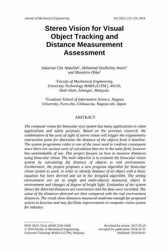
Figure 9. a) At 10m, the moving object showing that it is fairly detected.
b) After the moving object crossed the green lines, the object is shown
count from 1 to 2.
a) b)
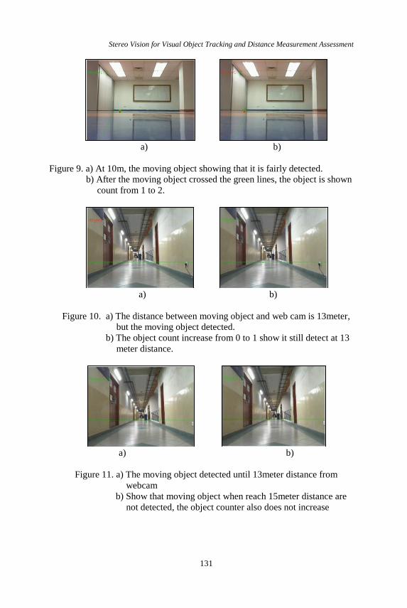
Figure 10. a) The distance between moving object and web cam is 13meter,
but the moving object detected.
b) The object count increase from 0 to 1 show it still detect at 13
meter distance.
a) b)
Figure 11. a) The moving object detected until 13meter distance from
webcam
b) Show that moving object when reach 15meter distance are
not detected, the object counter also does not increase

Sukarnur Che Abdullah et al.
132
Since, the size of room is 10.2-meter length in Figure 9, the experiment
cannot be carried out inside the room thus, we choose hallway outside to
continue the experiment as shown in Figure 10.
From the result 13 meter is the limit of the detected moving object as
shown in Figure 11. If the moving image is more than 13-meter distance, the
moving object look too small, thus it considered no changes in the background
image.
II. Speed of Moving object.
For moving object count function, the object must pass the green lines to be
count.
a) b)
Figure 12. a) At 1.5m/s object speed, the object are still detected and the
count is increase
b) At 3.0 m/s object speed show an example of detected moving
object but not counted.
From the result the threshold of the object speed for moving object to
be count is set to 1.5m/s. If the moving object speed is more than 1.5m/s, the
object will not be count even the moving object been detected and mark as
shown in Figure 12.
4 Conclusion There are a lot of binocular vision types that can be used for the distance measurement purposes. The most common one is trigonometry method that used triangle as the main concept for the calculation. A less demanding technique for calibrating extensive standard vision system should be produced. Presently, the main techniques for doing this is by utilizing an expansive checkerboard or physically extricating focuses from a huge object with highlight purposes of known measurements. Nevertheless, there is an easier step that may be used which is by anticipating a system, where a highlight focuses can be removed effectively, onto the side of a building or floor and taking pictures for adjustment. According to the previous researches that have been done, detecting objects contour is commonly simpler object geometry such

Stereo Vision for Visual Object Tracking and Distance Measurement Assessment
133
as straight lines, circle, square and rectangle [8][9]. This is because the objective itself is to measure the distance regardless the shape of the object [10].
As a conclusion, based on the data that have been obtained from this
experiment, this project can be concluded that the colour of an object does not
affect the depth map of the image. Although the colours are changed, the
distances of the object detected are quite similar with each other. On the
experimental analysis, the main factor that affects the distances that will be
computed is the range of distances from the binocular eyes system source itself
[11]. The further the objects from the camera, the higher percentage of errors
will be recorded. Therefore, the calibration of the cameras is important in order
to get the focus point from both images that act as the range precision. Other
than that, the control windows that control the parameters of the object need to
be detected are important too. It controls the program not to detect any other
components that have no relation to the distances that wanted to be measured.
The degree of light (lux point) is one of the critical parts of this experiment.
The large amount of light will induce glare for the binocular vision. This will
disturb the value of depth map that want to be calculated because the difficulty
to find the blob contour of the images. In this project, the experiment that have
been conducted conclude that the precision and accuracy of the distance
detected is based on the result of calibrated cameras and the amount of light
must be in the range of normal lux point otherwise new algorithm should be
designed. On the experimental analysis for the moving object, it shows that the
distance limit of the programming to detect moving object is more than
13meter. However, the result might not be obtained accurately due to the
interference from the outside such as wind and dim lighting, hence, the
objectives of this project are fulfilled.
5 References
[1] Howard IP, “Binocular correspondence and the Horopter”, In: Howard
IP,ed. Seeing in Depth, Howard, Ontrio: I. Porteous, 2002.
[2] Aslin RN, “Development of binocular fixation in robot vision”, J Exp
Psychol, 1977.
[3] Nathaniel J. Short, “3-D Generation from Flexible Stereo Vision
Systems”, Blacksburg, VA, December , 2009.
[4] Tim Morris, “Computer Vision and Image Processing. Palgrave
Macmilla” ISBN 0333-99451-5, 2004.
[5] http://maxembedded.com/2012/12/24/basic-concept-of-compter-vision/,
July 2017.
[6] Gary Bradski and Andrian Kaehler, “Learning OpenCV”. O’Reilly, 2008.
[7] SC Abdullah, Y Yusof, H Rashid, MI Nor Ma‘arof, “Rectification Y-
coordinate of epipolar geometry in calibration of binocular eye system”,
Procedia Computer Science, vol. 76, pp. 494-499, Jannuary 2015.

Sukarnur Che Abdullah et al.
134
[8] David G. Lowe, “3-Dimensional Object Recognition from 2 Dimensional
Image”, pp. 355-395. March, 1987.
[9] King-Sun Fu, Azriel. “Patern Recognition and Image Processing
Transaction on Computer”, vol. c-25, No 12. December, 1976.
[10] Jelmer de Vries, “Shape-Based Approach utilizing Artificial Neural
Network” Department of Computer Theory and Engineering, Vol.4, No.1,
February 2012.
[11] Tony Lindeberg, “Scale-space: A framework for handling image
structures at multiple scales” Department of Numerical Analysis and
Computing Science KTH, Royal Institute of Technology, Setempber
1996.