jeas_0912_774
5
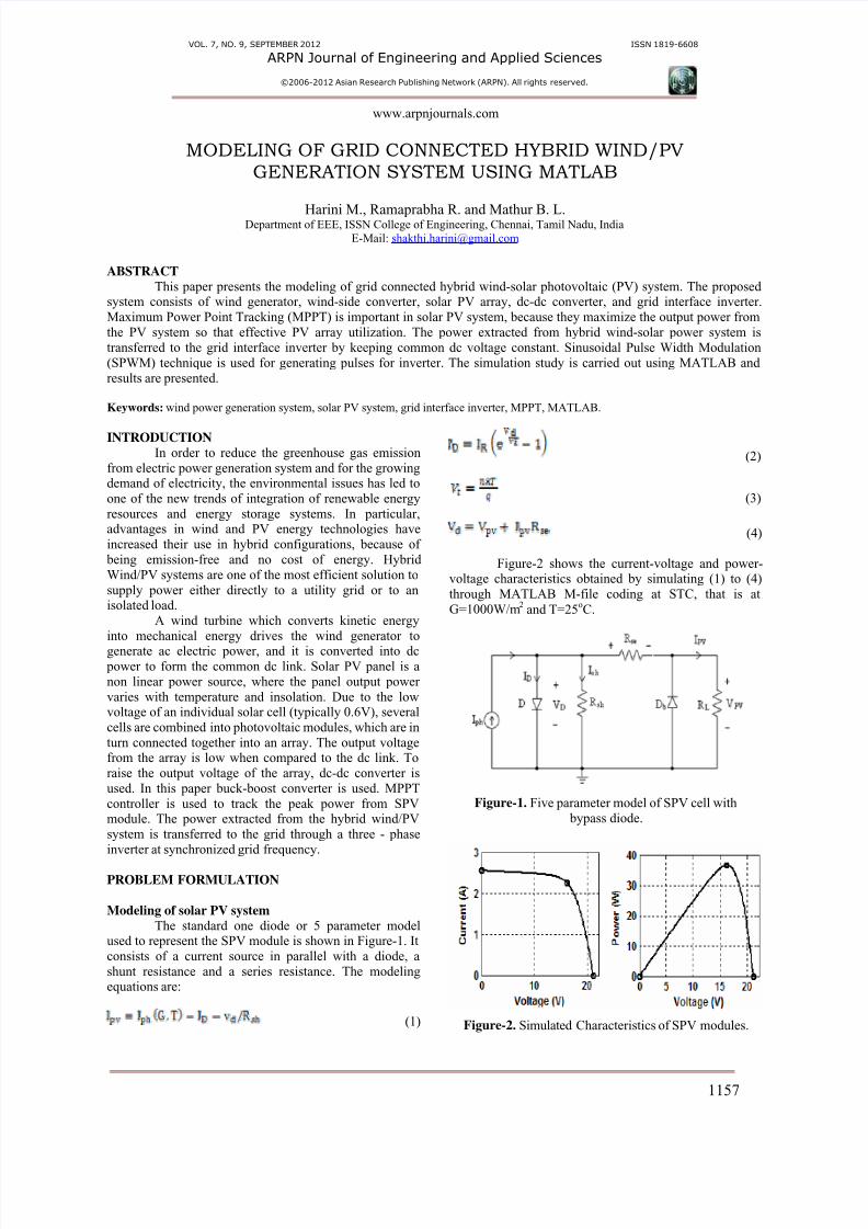
VOL. 7, NO. 9, SEPTEMBER 2012 ISSN 1819-6608 ARPN Journal of Engineering and Applied Sciences ©2006-2012 Asian Research Publishing Network (ARPN). All rights reserved. www.arpnjournals.com 1157 MODELING OF GRID CONNECTED HYBRID WIND/PV GENERATION SYSTEM USING MATLAB Harini M., Ramaprabha R. and Mathur B. L. Department of EEE, ISSN College of Engineering, Chennai, Tamil Nadu, India E-Mail: [email protected] ABSTRACT This paper presents the modeling of grid connected hybrid wind-solar photovoltaic (PV) system. The proposed system consists of wind generator, wind-side converter, solar PV array, dc-dc converter, and grid interface inverter. Maximum Power Point Tracking (MPPT) is important in solar PV system, because they maximize the output power from the PV system so that effective PV array utilization. The power extracted from hybrid wind-solar power system is transferred to the grid interface inverter by keeping common dc voltage constant. Sinusoidal Pulse Width Modulation (SPWM) technique is used for generating pulses for inverter. The simulation study is carried out using MATLAB and results are presented. Keywords: wind power generation system, solar PV system, grid interface inverter, MPPT, MATLAB. INTRODUCTION In order to reduce the greenhouse gas emission from electric power generation system and for the growing demand of electricity, the environmental issues has led to one of the new trends of integration of renewable energy resources and energy storage systems. In particular, advantages in wind and PV energy technologies have increased their use in hybrid configurations, because of being emission-free and no cost of energy. Hybrid Wind/PV systems are one of the most efficient solution to supply power either directly to a utility grid or to an isolated load. A wind turbine which converts kinetic energy into mechanical energy drives the wind generator to generate ac electric power, and it is converted into dc power to form the common dc link. Solar PV panel is a non linear power source, where the panel output power varies with temperature and insolation. Due to the low voltage of an individual solar cell (typically 0.6V), several cells are combined into photovoltaic modules, which are in turn connected together into an array. The output voltage from the array is low when compared to the dc link. To raise the output voltage of the array, dc-dc converter is used. In this paper buck-boost converter is used. MPPT controller is used to track the peak power from SPV module. The power extracted from the hybrid wind/PV system is transferred to the grid through a three - phase inverter at synchronized grid frequency. PROBLEM FORMULATION Modeling of solar PV system The standard one diode or 5 parameter model used to represent the SPV module is shown in Figure-1. It consists of a current source in parallel with a diode, a shunt resistance and a series resistance. The modeling equations are: (1) (2) (3) (4) Figure-2 shows the current-voltage and power- voltage characteristics obtained by simulating (1) to (4) through MATLAB M-file coding at STC, that is at G=1000W/m 2 and T=25 o C. Figure-1. Five parameter model of SPV cell with bypass diode. Figure-2. Simulated Characteristics of SPV modules.
-
Upload
sabir-khan -
Category
Documents
-
view
217 -
download
0
Transcript of jeas_0912_774
8/11/2019 jeas_0912_774
http://slidepdf.com/reader/full/jeas0912774 1/5
8/11/2019 jeas_0912_774
http://slidepdf.com/reader/full/jeas0912774 2/5
VOL. 7, NO. 9, SEPTEMBER 2012 ISSN 1819-6608
ARPN Journal of Engineering and Applied Sciences
©2006-2012 Asian Research Publishing Network (ARPN). All rights reserved.
www.arpnjournals.com
1158
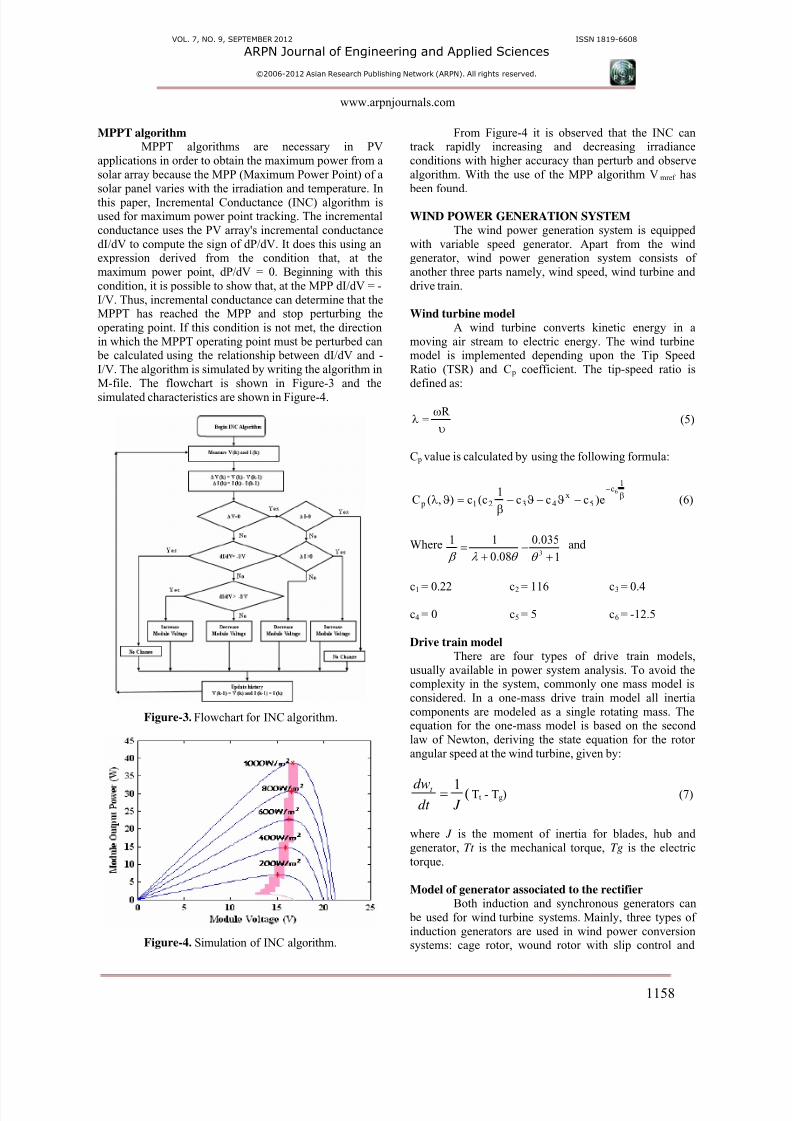
MPPT algorithm MPPT algorithms are necessary in PV
applications in order to obtain the maximum power from a
solar array because the MPP (Maximum Power Point) of a
solar panel varies with the irradiation and temperature. In
this paper, Incremental Conductance (INC) algorithm isused for maximum power point tracking. The incremental
conductance uses the PV array's incremental conductance
dI/dV to compute the sign of dP/dV. It does this using anexpression derived from the condition that, at the
maximum power point, dP/dV = 0. Beginning with this
condition, it is possible to show that, at the MPP dI/dV = -
I/V. Thus, incremental conductance can determine that theMPPT has reached the MPP and stop perturbing the
operating point. If this condition is not met, the direction
in which the MPPT operating point must be perturbed can be calculated using the relationship between dI/dV and -
I/V. The algorithm is simulated by writing the algorithm in
M-file. The flowchart is shown in Figure-3 and the
simulated characteristics are shown in Figure-4.
Figure-3. Flowchart for INC algorithm.
Figure-4. Simulation of INC algorithm.
From Figure-4 it is observed that the INC cantrack rapidly increasing and decreasing irradiance
conditions with higher accuracy than perturb and observe
algorithm. With the use of the MPP algorithm Vmref has
been found.
WIND POWER GENERATION SYSTEM
The wind power generation system is equipped
with variable speed generator. Apart from the windgenerator, wind power generation system consists of
another three parts namely, wind speed, wind turbine and
drive train.
Wind turbine model
A wind turbine converts kinetic energy in a
moving air stream to electric energy. The wind turbinemodel is implemented depending upon the Tip Speed
Ratio (TSR) and C p coefficient. The tip-speed ratio is
defined as:
υ
ω=λ
R (5)
C p value is calculated by using the following formula:
β−
−ϑ−ϑ−β
=ϑλ
1c
5x
4321 p
6
e)ccc1
c(c),(C (6)
Where 1
035.0
08.0
113+
−+
=θ θ λ β
and
c1 = 0.22 c2 = 116 c3 = 0.4
c4 = 0 c5 = 5 c6 = -12.5
Drive train model There are four types of drive train models,
usually available in power system analysis. To avoid thecomplexity in the system, commonly one mass model is
considered. In a one-mass drive train model all inertia
components are modeled as a single rotating mass. Theequation for the one-mass model is based on the second
law of Newton, deriving the state equation for the rotor
angular speed at the wind turbine, given by:
(1 J dt
dwt = Tt - Tg) (7)
where J is the moment of inertia for blades, hub and
generator, Tt is the mechanical torque, Tg is the electric
torque.
Model of generator associated to the rectifier
Both induction and synchronous generators can
be used for wind turbine systems. Mainly, three types of
induction generators are used in wind power conversionsystems: cage rotor, wound rotor with slip control and
8/11/2019 jeas_0912_774
http://slidepdf.com/reader/full/jeas0912774 3/5
VOL. 7, NO. 9, SEPTEMBER 2012 ISSN 1819-6608
ARPN Journal of Engineering and Applied Sciences
©2006-2012 Asian Research Publishing Network (ARPN). All rights reserved.
www.arpnjournals.com
1159
doubly fed induction rotors. In this paper, gearless multi- pole permanent magnet synchronous generator (PMSG) is
chosen and it is attractive because it offers better
performance due to higher efficiency and less maintenance
since it does not have rotor current and can be used
without a gearbox, which also implies the reduction of theweight of the nacelle, and reduction of costs. It produces
electricity from the mechanical energy obtained from the
wind. The wind turbine controller consists of three- phasediode bridge rectifier which converts the alternating
current from wind turbine to direct current. The three
phase diode bridge rectifier is comprised of six rectifier
diodes. The variable frequency output voltages from windturbines are rectified to unregulated dc voltages.
Figure-5 shows the input waveform from wind
turbine and Figure-6 shows the output waveform of three phase diode bridge rectifier.
Figure-5. Input waveform from wind turbine.
Figure-6. Output waveform of three-phase diode
bridge rectifier.
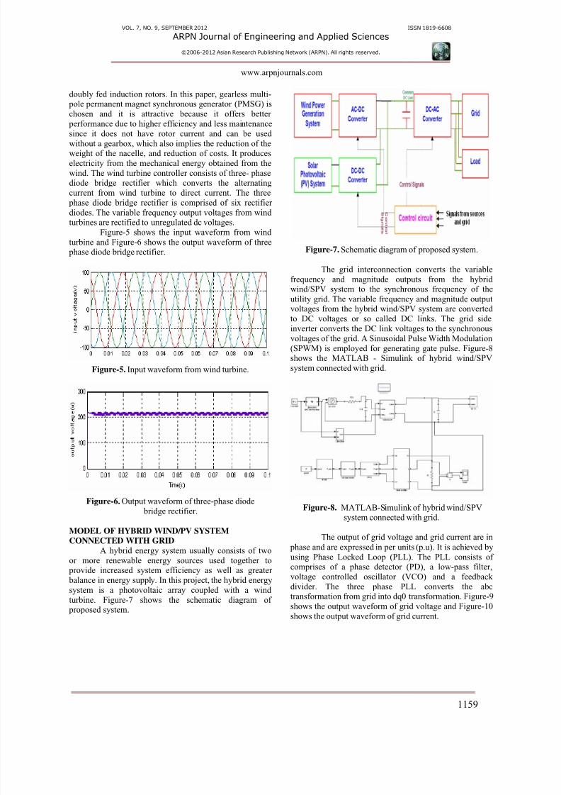
MODEL OF HYBRID WIND/PV SYSTEM
CONNECTED WITH GRID
A hybrid energy system usually consists of two
or more renewable energy sources used together to provide increased system efficiency as well as greater
balance in energy supply. In this project, the hybrid energy
system is a photovoltaic array coupled with a wind
turbine. Figure-7 shows the schematic diagram of proposed system.
Figure-7. Schematic diagram of proposed system.
The grid interconnection converts the variable
frequency and magnitude outputs from the hybridwind/SPV system to the synchronous frequency of the
utility grid. The variable frequency and magnitude outputvoltages from the hybrid wind/SPV system are converted
to DC voltages or so called DC links. The grid side
inverter converts the DC link voltages to the synchronous
voltages of the grid. A Sinusoidal Pulse Width Modulation
(SPWM) is employed for generating gate pulse. Figure-8shows the MATLAB - Simulink of hybrid wind/SPV
system connected with grid.
Figure-8. MATLAB-Simulink of hybrid wind/SPVsystem connected with grid.
The output of grid voltage and grid current are in
phase and are expressed in per units (p.u). It is achieved by
using Phase Locked Loop (PLL). The PLL consists ofcomprises of a phase detector (PD), a low-pass filter,
voltage controlled oscillator (VCO) and a feedback
divider. The three phase PLL converts the abctransformation from grid into dq0 transformation. Figure-9
shows the output waveform of grid voltage and Figure-10
shows the output waveform of grid current.
8/11/2019 jeas_0912_774
http://slidepdf.com/reader/full/jeas0912774 4/5
VOL. 7, NO. 9, SEPTEMBER 2012 ISSN 1819-6608
ARPN Journal of Engineering and Applied Sciences
©2006-2012 Asian Research Publishing Network (ARPN). All rights reserved.
www.arpnjournals.com
1160
0 0.01 0.02 0.03 0.04 0.05 0.06 0.07 0.08 0.09 0.1-1.5
-1
-0.5
0
0.5
1
1.5
Time(s)
g r i d
v o
l t a g e ( p . u )
Figure-9. Output waveform of grid voltage.
0 0.01 0.02 0.03 0.04 0.05 0.06 0.07 0.08 0.09 0.1-4
-2
0
2
4
6
Time(s)
g r i d
c u r r e n t ( p . u )
Figure-10. Output waveform of grid current.
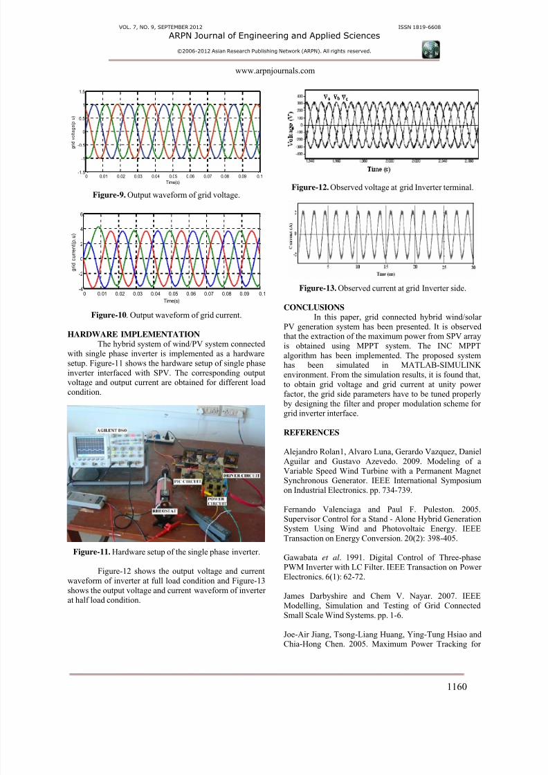
HARDWARE IMPLEMENTATION
The hybrid system of wind/PV system connected
with single phase inverter is implemented as a hardware
setup. Figure-11 shows the hardware setup of single phase
inverter interfaced with SPV. The corresponding outputvoltage and output current are obtained for different load
condition.
Figure-11. Hardware setup of the single phase inverter.
Figure-12 shows the output voltage and current
waveform of inverter at full load condition and Figure-13
shows the output voltage and current waveform of inverter
at half load condition.
Figure-12. Observed voltage at grid Inverter terminal.
Figure-13. Observed current at grid Inverter side.
CONCLUSIONS
In this paper, grid connected hybrid wind/solar
PV generation system has been presented. It is observedthat the extraction of the maximum power from SPV array
is obtained using MPPT system. The INC MPPT
algorithm has been implemented. The proposed systemhas been simulated in MATLAB-SIMULINK
environment. From the simulation results, it is found that,
to obtain grid voltage and grid current at unity power
factor, the grid side parameters have to be tuned properly
by designing the filter and proper modulation scheme forgrid inverter interface.
REFERENCES
Alejandro Rolan1, Alvaro Luna, Gerardo Vazquez, Daniel
Aguilar and Gustavo Azevedo. 2009. Modeling of a
Variable Speed Wind Turbine with a Permanent MagnetSynchronous Generator. IEEE International Symposium
on Industrial Electronics. pp. 734-739.
Fernando Valenciaga and Paul F. Puleston. 2005.
Supervisor Control for a Stand - Alone Hybrid Generation
System Using Wind and Photovoltaic Energy. IEEE
Transaction on Energy Conversion. 20(2): 398-405.
Gawabata et al. 1991. Digital Control of Three-phase
PWM Inverter with LC Filter. IEEE Transaction on Power
Electronics. 6(1): 62-72.
James Darbyshire and Chem V. Nayar. 2007. IEEE
Modelling, Simulation and Testing of Grid Connected
Small Scale Wind Systems. pp. 1-6.
Joe-Air Jiang, Tsong-Liang Huang, Ying-Tung Hsiao andChia-Hong Chen. 2005. Maximum Power Tracking for

8/11/2019 jeas_0912_774
http://slidepdf.com/reader/full/jeas0912774 5/5
VOL. 7, NO. 9, SEPTEMBER 2012 ISSN 1819-6608
ARPN Journal of Engineering and Applied Sciences
©2006-2012 Asian Research Publishing Network (ARPN). All rights reserved.
www.arpnjournals.com
1161
Photovoltaic Power Systems. Tamkang Journal of Scienceand Engineering. 8(2): 147-153.
R. Ramaprabha and B.L. Mathur. 2008. Modeling and
Simulation of Solar PV Array under Partial Shaded
conditions. In: proceeding of IEEE conference ICSET2008 at Singapore. pp. 7-11.
Seul Ki Kim, Jin Hong Jeon, Chang Hee Cho, Jong BoAhn and Sae Hyuk Kwon. 2008. Dynamic Modeling and
Control of Grid- Connected Hybrid Generation System
with Versatile Power Transfer. IEEE Transactions on
Industrial Electronics. 55(4): pp. 1677-1688.
www.mathworks.com.