IMPORTANTE - steren.com.mx · • No exponga el equipo ni sus accesorios al polvo, humo o vapor....
66
Transcript of IMPORTANTE - steren.com.mx · • No exponga el equipo ni sus accesorios al polvo, humo o vapor....

2
ARD-020Gracias por la compra de este producto Steren.
Este manual contiene todas las indicaciones necesarias para manejar su nueva Tarjeta programadora compatible con Arduino tipo Leonardo.
Por favor, revíselo completamente para estar seguro de cómo utilizar apropiadamente el producto.
Para apoyo, compras y todo lo nuevo que tiene Steren, visite nuestro sitio web:
www.steren.com
TARJETA PROGRAMADORA COMPATIBLE CON ARDUINO TIPO
LEONARDO
La información que se muestra en este manual sirve únicamente como referencia sobre el producto. Debido a actualizaciones pueden existir diferencias.
Por favor, consulte nuestra página web (www.steren.com) para obtener la versión más reciente del instructivo.

3
IMPORTANTE
• Mantenga el equipo fuera del alcance de los niños.
• No exponga el equipo a temperaturas extremas.
• No use ni almacene este equipo en lugares donde existan goteras o salpicaduras de agua.
• Evite las caídas del equipo, ya que podría sufrir daños.
•No coloque el equipo ni los accesorios sobre superfi cies inclinadas, inestables o sometidas a vibraciones.
• No coloque objetos pesados sobre el equipo ni sobre sus accesorios.
• No exponga el equipo ni sus accesorios al polvo, humo o vapor.
• La Tarjeta programadora con micro controlador Atmel MEGA32U4 le brinda la posibilidad de utilizar todo los puertos de entrada y salida, ayudando a los desarrolladores estudiantes y hoobistas a no preocuparse por la etapa de control.
• La interfaz de comunicación y de programación se realiza utilizando el software libre que utiliza Arduino, se conecta a la computadora por medio del puerto USB e incorpora puerto ISCP.

4
CÓMO EMPEZAR CON ARDUINOEste manual le ayudará a entender lo que es y cómo funciona Arduino para comenzar a construir sus propios proyectos electrónicos.
Arduino es una plataforma de electrónica abierta para la creación de prototipos basada en software y hardware fl exibles y fáciles de usar. Tiene todo lo que necesita para uso básico soldado en una pequeña placa de circuito. La placa contiene el microcontrolador y ofrece un cómodo acceso a las entradas y salidas. Las entradas son dispositivos como sensores (sensores de luz, termómetros, giroscopios, etc.) y elementos de interfaz humana (botones, interruptores, perillas). Las salidas son todos los elementos electrónicos que quiera ser capaz de controlar, tales como luces, pantallas, motores y servos. Un microcontrolador tiene todas las partes básicas de un ordenador (procesador, memoria, pines de entrada/salida) en un solo chip y ejecuta el software que se carga sobre ella desde una computadora, lo que le permite manipular los resultados basados en datos que recibe de las entradas.Arduino es open source. Como hardware de código abierto, los esquemas para Arduino están disponibles para cualquier persona gratuitamente, por si quiere comprar los componentes electrónicos y una placa y construir su propio Arduino. Existe una enorme gama de proyectos que necesitan un microcontrolador. Un proyecto simple podría ser algo como una tira de luz LED. Un circuito básico puede encender las luces LED, pero con el fi n de conseguir que cambie de color y ejecutar patrones necesita un microcontrolador. Proyectos más complejos podrían ser un brazo robótico, una exhibición de LED holográfi co o una caja de arena de gato auto limpiable.
¿Qué es Arduino?

5
PROGRAMACIÓN ARDUINO1. Descargue el entorno de desarrollo de Arduino (www.arduino.cc) e instálelo en su PC. El ambiente está disponible para Windows, Mac y Linux e incluye todo lo que necesita para empezar a programar.2. Conecte el Arduino a la computadora y si está usando una máquina Windows, espere a que se instale el controlador. 3. Cuando comience a usar el editor de Arduino, deberá confi gurar en el menú Herramientas, en la parte superior del editor, la opción de tarjeta y la opción de Puerto Serial; en la primera seleccione el modelo de Arduino que compró. En la segunda elija el puerto al que está conectado el Arduino. Si tiene dudas acerca de este puerto, simplemente desconecte el Arduino y la opción que desaparezca es su puerto.
Un escudo es una placa de circuito adicional a su Arduino. Generalmente, un escudo se coloca encima de la placa base Arduino, se conecta con sus pines I/O y permite al Arduino especializarse añadiendo capacidades adicionales, o proporcionando una interfaz más conveniente para su proyecto. Por ejemplo, un escudo podría permitir integrar un chip GPS o una tarjeta SD a su proyecto. Algunos escudos se pueden apilar uno encima del otro, para agregar varias funciones adicionales.
Deberá descargar un hardware adicional para programar el circuito. Necesitará un cable USB para programarlo y si quiere ser capaz de ejecutar su proyecto cuando no está cerca de la computadora, necesitará un adaptador de corriente AC-DC o batería y cable. Usted encontrará estos componentes en Steren.
Escudos

6
SKETCHES
Finalmente, estará listo para escribir programas (el editor de Arduino se refi ere a ellos como “sketches”) para su proyecto. Necesitará cierta familiaridad con programación en C++, variables, funciones, declaraciones “if” y bucles, pero los sketches Arduino suelen ser más simples.
La mejor manera de aprender programación de Arduino es a través de los sketches de ejemplo incluidos en el IDE de Arduino. Éstos se encuentran en el menú Archivo>Ejemplos y puede encontrar muchos ejemplos en Internet.
Una vez que ha escrito un sketch, simplemente haga clic en el botón Cargar y éste será enviado a su placa Arduino. El microcontrolador se reiniciará y ejecutará su sketch hasta subir uno diferente.
A continuación se muestran pequeños proyectos paso a paso.
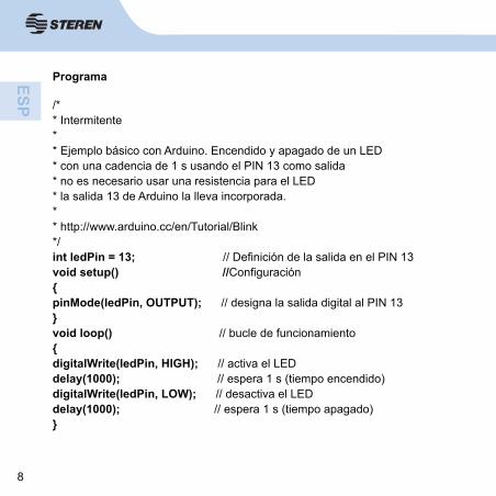
Se trata de realizar un ejercicio básico que consiste en encender y apagar un LED que conectamos en el PIN 13 de Arduino confi gurado como salida. El tiempo de encendido y apagado es de 1 segundo.
Diagrama y Esquema
Dado que el PIN 13 de Arduino lleva incorporada una resistencia interior, el diodo LED se coloca sin resistencia en serie; en el caso de colocar el diodo LED en otra salida, deberíamos colocar una resistencia de entre 220 y 500 ohmios, dependiendo del consumo de corriente del diodo.
1. Intermitente

7
Conexión para realizar la salida por el PIN 10.
IORE
FRE
SET
3V3
5V GND
GND
V1n
SCL
SDA
AREF
GND
13 12 11 10 9 8 7 6 5 4 3 2 1 0
A0 A1 A2 A3 A4 A5TX
1 1
AX1
0
POWER ANALOG IN
DIGIRAL (PWM)A11
A10
A9 A8 A7 A6
IORE
FRE
SET
3V3
5V GND
GND
V1n
SCL
SDA
AREF
GND
13 12 11 10 9 8 7 6 5 4 3 2 1 0
A0 A1 A2 A3 A4 A5TX
1 1
AX1
0
POWER ANALOG IN
DIGIRAL (PWM)A11
A10
A9 A8 A7 A6
8
Programa
/** Intermitente** Ejemplo básico con Arduino. Encendido y apagado de un LED* con una cadencia de 1 s usando el PIN 13 como salida* no es necesario usar una resistencia para el LED* la salida 13 de Arduino la lleva incorporada.** http://www.arduino.cc/en/Tutorial/Blink*/int ledPin = 13; // Defi nición de la salida en el PIN 13void setup() //Confi guración{pinMode(ledPin, OUTPUT); // designa la salida digital al PIN 13}void loop() // bucle de funcionamiento{digitalWrite(ledPin, HIGH); // activa el LEDdelay(1000); // espera 1 s (tiempo encendido)digitalWrite(ledPin, LOW); // desactiva el LEDdelay(1000); // espera 1 s (tiempo apagado)}

9
Cuando presiona el pulsador (entrada 5 a “0”), la salida 13 se enciende y se apaga de forma intermitente.
Funcionamiento:
Cuando la E5 = 1 Entonces S13 = 0
Cuando la E5 = 0 Entonces S13 = 0-1 (Intermitente 200,200 ms)
10 K
2. Alarma

10
Programa
int ledPin= 13; // elija el PIN para el LEDint inPin= 5; // choose the input pin (for a pushbutton) (elija el PIN de entrada (para un botón)int val= 0; // variable for reading the pin status (variable para lectura de estatus del PIN)void setup() {pinMode(ledPin, OUTPUT); // declare LED as output (declare el LED como salida)pinMode(inPin, INPUT); // declare pushbutton as input (declare el botón como salida)}void loop(){val= digitalRead(inPin); // lee valor de entradaif(val== HIGH) { // chequea si el valor leído es “1” (botón presionado)digitalWrite(ledPin, LOW); // pone el LED en OFF} else{digitalWrite(ledPin, LOW); // parpadea el LEDdelay(200);digitalWrite(ledPin, HIGH);delay(200);}}

11
Trata de encender y apagar 3 LEDs colocados en las salidas 6, 7 y 8 (PIN 6, PIN 7 y PIN 8) con una cadencia de 200 ms. Las variables asignadas a cada LED son ledPin1, ledPin2 y ledPin3.
3. Secuencia Básica de 3 LEDs
8 76GND

12
Programa
// Encendido y apagado de 3 LEDsint ledPin1 = 6; // Defi ne las salidas de los LEDsint ledPin2 = 7;int ledPin3 = 8;void setup() { // Confi gura las SALIDASpinMode(ledPin1, OUTPUT); // declarar LEDs como SALIDASpinMode(ledPin2, OUTPUT);pinMode(ledPin3, OUTPUT);digitalWrite(ledPin1, LOW); // Apaga los LEDsdigitalWrite(ledPin2, LOW);digitalWrite(ledPin3, LOW);}void loop(){ //Bucle de FuncionamientodigitalWrite(ledPin1, HIGH); // Apaga y enciende los LEDs cada 200 msdelay(200);digitalWrite(ledPin1, LOW);digitalWrite(ledPin2, HIGH);delay(200);digitalWrite(ledPin2, LOW);digitalWrite(ledPin3, HIGH);delay(200);digitalWrite(ledPin3, LOW);}

13
Se trata de contar las veces que se pulsa un botón conectado en la entrada 7 de Arduino al mismo tiempo que cada vez que contamos encendemos el LED conectado en la salida 13. El valor de la variable que almacena el número de impulsos generados se envía a la PC para que se visualice en la pantalla.
4. Contador
10 K

14
Programa Contador/* Detecta si el botón conectado a la entrada 7 ha sido presionado y enciende el LED* Envía al PC el valor de la variable de cuenta “Contador” vía puerto serie.** Christian Nold & Erica Calogero**/int LED = 13;int Boton = 7;int valor = 0;int contador = 0;int estadoanteriorboton = 0;void setup(){Serial.begin(9600); // Confi gura velocidad de transmisión a 9600pinMode(LED, OUTPUT); // inicializa como salida digital el pin 13pinMode(Boton, INPUT); // inicializa como entrada digital el 7digitalWrite(Boton,HIGH); // Habilitamos la resitencia interna Pull-up del PIN7}void loop(){valor = digitalRead(Boton); // lee el valor de la entrada digital pin 7digitalWrite(LED, !valor); // Escribimos en la salida el valor leído negadoif(valor != estadoanteriorboton){if(valor == 1){

15
contador++;Serial.print(contador);Serial.write(10);Serial.write(13);}}estadoanteriorboton = valor;}Podríamos prescindir de la resistencia colocada con el pulsador si se habilita la resistencia interna Pull-up de la entrada PIN7, en ese caso el circuito quedaría como el siguiente:

16
El programa en este caso sería muy parecido al anterior. Obsérvese que ahora al pulsar el botón introducimos un “=” en el PIN7, por lo tanto, si quiero que se encienda la salida PIN13 debo escribir en ella el valor leído del pulsador negado, es decir “!valor”.
Programa Contador Modifi cado
/* Detecta si el botón conectado a la entrada 7 ha sido presionado y enciende el LED* Envía a la PC el valor de la variable de cuenta “Contador” vía puerto serie.** Christian Nold & Erica Calogero J.M. Ruiz**/int LED = 13;int Boton = 7;int valor = 0;int contador = 0;int estadoanteriorboton = 0;void setup(){Serial.begin(9600); // Confi gura velocidad de transmisión a 9600pinMode(LED, OUTPUT); // inicializa como salida digital el pin 13pinMode(Boton, INPUT); // inicializa como entrada digital el 7digitalWrite(Boton,HIGH); // Habilitamos la resitencia interna Pull-up del PIN7}void loop()

17
{valor = digitalRead(Boton); // lee el valor de la entrada digital pin 7digitalWrite(LED, !valor); // Escribimos en la salida el valor leído negadoif(valor != estadoanteriorboton){if(valor == 1){contador++;Serial.print(contador);Serial.write(10);Serial.write(13);}}estadoanteriorboton = valor;}
Se trata de confi gurar un canal de entrada analógico pin 5 y enviar el valor leído a la PC para visualizarlo.
5. Entrada Analógica

18
Programa
/* Entrada Analógica */int potPin = 5; // selecciona el pin de entrada para colocar el potenciómetroint val = 0; // variable para almacenar el valor leído por la entrada analógicavoid setup() {Serial.begin(9600);}void loop() {val = analogRead(potPin); // lee el valor del canal de ENTRADA analógicaSerial.print(val); // Envía al PC el valor analógico leído y lo muestra en pantallaSerial.write(10);delay(100);}
Con este ejemplo vamos a controlar la velocidad de un motor de cc mediante la utilización de un transistor BD137. Se trata de utilizar la posibilidad de enviar una señal de PWM a una de las salidas confi gurables como salidas analógicas.
6. Control de un motor de cc con un transistor

19
Tenga en cuenta que el motor debe ser de bajo consumo por dos motivos: primero porque si alimentamos en las pruebas desde el conector USB no debemos sacar demasiada corriente de la computadora y segundo, porque el transistor es de una corriente limitada.
El diodo 1N4001 se coloca como protección para evitar que las corrientes inversas creadas en el bobinado del motor puedan dañar el transistor.

20
La tensión que sacaremos a la salida 10 (analógica tipo PWM) variará en forma de rampa ascendente y descendente de manera cíclica, tal como vemos en la fi gura. Este efecto lo conseguimos con una estructura del tipo for:
for(valor = 0 ; valor <= 255; valor +=5) (ascendente)for(valor = 255; valor >=0; valor -=5) (descendente)
Obsérvese que los incrementos del valor de la tensión van de 5 en 5 y tenemos que considerar que 0v equivale a 0 y 5 v equivale a 255.

21
Variante del montaje: Control de la velocidad mediante un potenciómetro.
Se trata de controlar la velocidad a nuestro gusto, es decir, mediante un potenciómetro que se coloca en una de las entradas analógicas y en función del valor que se lea en la entrada, así girará más o menos rápido el motor.
Programa
int valor = 0; // variable que contiene el valor a sacar por el terminal analógicoint motor = 10; // motor conectado al PIN 10void setup() { } // No es necesariovoid loop() {for(valor = 0 ; valor <= 255; valor +=5) {// se genera una rampa de subida de tensión de 0 a 255, es decir, de 0 a 5vanalogWrite(motor, valor);delay(30); // espera 30 ms para que el efecto sea visible}for(valor = 255; valor >=0; valor -=5) {// se genera una rampa de bajada de tensión de 255 a 0, es decir, de 5 a 0vanalogWrite(motor, valor);delay(30);}}

22
Programa
int valor = 0; // variable que contiene el valor a sacar por el terminal analógicoint motor = 10; // motor conectado al PIN 10int potenciometro=0; // Se defi ne la entrada analógicavoid setup() { } // No es necesariovoid loop() {valor = analogRead(potenciometro); // se lee el valor de la entrada analógicay se asigna a valanalogWrite(motor, valor); // Se manda a la salida analógica 0 el valor leídodelay(30); // espera 30 ms para que el efecto sea visible}Esquema

23
Con esta aplicación vamos a mover un motor de cc usando un CI de potencia, específi co para estas aplicaciones. El circuito podrá mover hasta dos motores, nosotros sólo lo haremos con uno.
Como ventana en este montaje podremos mover el motor en los dos sentidos de giro, cosa que con el anterior montaje no podíamos.
El funcionamiento será como el primer montaje del motor anterior, es decir, vamos a crear una rampa de subida de tensión y una de bajada con el fi n de que el motor modifi que su velocidad de modo automático.
Control o Driver de un motor de continua:
Los dos parámetros que queremos controlar de un motor de continua son su dirección de giro y su velocidad. La dirección se controla cambiando su polaridad. En cambio, para su velocidad, debemos utilizar la técnica de modulación por ancho de pulso-PWM.
Aquí hay algunos gráfi cos donde se muestra la relación entre la señal de pulsos (PWM) y el voltaje efectivo:
7. Control de un motor de cc con el driver L293DVo
ltaje
Tiempo
Voltaje efectivo

24
Cuando el tiempo que el pulso está activo es la mitad del periodo de la señal o el parámetro duty cycle está al 50%, el voltaje efectivo es la mitad del voltaje total de entrada.
Cuando el tiempo que el pulso está activo es la mitad del periodo de la señal o el parámetro duty cycle está al 50%, el voltaje efectivo es la mitad del voltaje total de entrada.
Cuando el duty cycle es reducido al 25%, el voltaje efectivo es un cuarto del voltaje total de entrada. Entonces la velocidad del motor disminuye.
De esta forma, controlando el duty cycle o el tiempo que el pulso está activo (frecuencia), podemos controlar la velocidad del motor de continua.
Una forma de realizar dicho control en Arduino es utilizando la salida analógica PWM.
Hay que recordar que la señal de salida PWM (pines 9, 10) es una señal de frecuencia constante (30769 Hz) y que sólo nos permite cambiar el “duty cycle” o el tiempo que el pulso está activo (on) o inactivo (off) utilizando la función analogWrite().
Volta
je
Tiempo
Voltaje efectivo

25
La otra forma es generando señales PWM utilizando la capacidad del microprocesador a través de la función digitalWrite().
Si queremos controlar simultáneamente la velocidad y dirección de un motor, necesitamos utilizar un circuito integrado o chip, llamado de forma general “puentes H”, por ejemplo como el L293D.Chip L293D/B (puente H):
Es un circuito integrado o chip que puede ser utilizado para controlar simultáneamente la velocidad y dirección de dos motores de continua (contiene dos puentes H). La diferencia entre el modelo L393D y L293B es que el primero viene con diodos de protección que evitan los daños generados por los picos de voltaje que puede producir el motor.
Contiene 4 pines digitales (2, 7, 10, 15) para controlar la dirección de los motores.
Al puertoparalelo:
pines1 y 2

26
Los pines “enable” (1, 9) admiten como entrada una señal PWM y se utiliza para controlar la velocidad de los motores con la técnica de modulación de ancho de pulso.
Los motores van conectados entre uno de los pines 3, 6, 11, o 14. La tensión Vss es la que alimentará o dará potencia al motor.
Montaje Básico: Control simple de un motor con el CI L293 a velocidad constante
Primero sólo vamos a demostrar el control de la velocidad de un motor de continua a través del integrado L293D. Para ello fi jamos los pines de control de dirección a 5v y 0v, de forma que sólo girará en un sentido. Si queremos cambiar el sentido, sólo será necesario cambiar dicha polarización.
Programa
// Control simple de un motor con el CI L293 a velocidad constanteint motorpin =10; // PIN de salida analógica PWMvoid setup() { }void loop() {analogWrite(motorpin, 125); // activa el motor a una velocidad constantedelay(100); // espera 100 ms para la próxima lectura}

27
Esquema
IOREF
RESET
3V3
5V GND VIN 0 1 2 3 4 5 6 7 8 9 10 11 12 13 14 15
DIGITAL
AREF GND 13 12 11 10 9 8
TXD3
14
RXD3
15
TXD2
16
RXD2
17
TXD1
18
RXD2
17
SDA
20
SCL
21
COMMUNICATION
PWM
POWER ANALOG IN
7 6 5 4 3 2 1 0 22
24
26
28
30
32
34
36
38
40
42
44
46
48
50
52
8. Control de un motor: velocidad variable y sentido de giro variable

28
Programa
// Control de Motor con driver L293Dint valor = 0; // variable que contiene el valorint motorAvance = 10; // Avance motor --> PIN 10int motorRetroceso = 11; // Retroceso motor --> PIN 11void setup() { } // No es necesariovoid loop() {analogWrite(motorRetroceso, 0); // Motor hacia delante ... sube la velocidadfor(valor = 0 ; valor <= 255; valor+=5) {analogWrite(motorAvance, valor);delay(30);}for(valor = 255; valor >=0; valor-=5) { // Motor hacia delante ... baja lavelocidadanalogWrite(motorAvance, valor);delay(30);}analogWrite(motorAvance, 0); // Motor hacia detrás ... sube la velocidadfor(valor = 0 ; valor <= 255; valor+=5) {analogWrite(motorRetroceso, valor);delay(30);}for(valor = 255; valor >=0; valor-=5) { // Motor hacia detrás ... baja la velocidadanalogWrite(motorRetroceso, valor);delay(30);}}

29
Este ejemplo enseña cómo encender una bombilla de 120 V de corriente alterna (AC) mediante un circuito de 5 V de corriente continua (DC) gobernado por Arduino. Se puede utilizar con cualquier otro circuito de 120 V con un máximo de 10 A (con el relé del ejemplo).¿Qué es un relevador?El relevador o relé es un dispositivo electromecánico que funciona como un interruptor controlado por un circuito eléctrico en el que, por medio de un electroimán, se acciona un juego de uno o varios contactos que permiten abrir o cerrar otros circuitos eléctricos independientes. De aquí extraemos una información muy importante: Podemos separar dos circuitos de forma que funcionen con voltajes diferentes.
9. Utilizar un relevador para encender dispositivos de 120 V
IOREF
RESET
3V3
5V GND VIN 0 1 2 3 4 5 6 7 8 9 10 11 12 13 14 15
DIGITAL
AREF GND 13 12 11 10 9 8
TXD3
14
RXD3
15
TXD2
16
RXD2
17
TXD1
18
RXD2
17
SDA
20
SCL
21
COMMUNICATION
PWM
POWER ANALOG IN
7 6 5 4 3 2 1 0 22
24
26
28
30
32
34
36
38
40
42
44
46
48
50
52
Uno a 5 V (Arduino) y otro a 120 V (la bombilla).Como se ve en el esquema inferior, hay dos circuitos. El del cableado NEGRO funciona a 5 V de DC y el del cableado ROJO a 120 V de AC.
110 V

30
Programa
/*Enciende y apaga una bombilla de 220 V, cada 2 segundos, medianteun relé conectado al PIN 8 de Arduino*/int relayPin = 8; // PIN al que va conectado el relévoid setup(){pinMode(relayPin, OUTPUT);}void loop() {digitalWrite(relayPin, HIGH); // ENCENDIDOdelay(2000);digitalWrite(relayPin, LOW); // APAGADOdelay(2000);}

31
El diseño del producto y las especifi caciones pueden cambiar sin previo aviso.
ESPECIFICACIONESMicro controlador: MEGA32U4
Alimentación: 5-12 V - - -
Frecuencia de operación: 16 MHz
Puertos de entrada análoga: 12
Puertos de entrada/salida digital: 20 (incluyendo puertos PWM)
Capacidad de memoria fl ash: 32 kB
SRAM: 2,5 kB
EEPROM: 1 kB
Boot loader: Leonardo
Salida PWM: Sí
Salida de voltaje: 5 V - - -
Switch reset: Sí
Comunicación a la PC: USB
Software empleado: Arduino

32
Modelo: Tarjeta programadora compatible con Arduino tipo Leonardo Producto: ARD-020Marca: Steren
PÓLIZA DE GARANTÍAEsta póliza garantiza el producto por el término de un año en todas sus partes y mano de obra, contra cualquier defecto de fabricación y funcionamiento, a partir de la fecha de entrega.
CONDICIONES1.- Para hacer efectiva la garantía, presente esta póliza y el producto, en donde fue adquirido o en Electrónica Steren S.A. de C.V.2.- Electrónica Steren S.A de C.V. se compromete a reparar el producto en caso de estar defectuoso sin ningún cargo al consumidor. Los gastos de transportación serán cubiertos por el proveedor.3.- El tiempo de reparación en ningún caso será mayor a 30 días, contados a partir de la recepción del producto en cualquiera de los sitios donde pueda hacerse efectiva la garantía.4.- El lugar donde puede adquirir partes, componentes, consumibles y accesorios, así como hacer válida esta garantía es en cualquiera de las direcciones mencionadas posteriormente.
ESTA PÓLIZA NO SE HARÁ EFECTIVA EN LOS SIGUIENTES CASOS:1.- Cuando el producto ha sido utilizado en condiciones distintas a las normales.2.- Cuando el producto no ha sido operado de acuerdo con el instructivo de uso.3.- Cuando el producto ha sido alterado o reparado por personal no autorizado por Electrónica Steren S.A. de C.V.El consumidor podrá solicitar que se haga efectiva la garantía ante la propia casa comercial donde adquirió el producto. Si la presente garantía se extraviara, el consumidor puede recurrir a su proveedor para que le expida otra póliza, previa presentación de la nota de compra o factura respectiva.
DATOS DEL DISTRIBUIDORNombre del Distribuidor __________________________Domicilio ______________________________________Producto ______________________________________Marca ________________________________________Modelo _______________________________________Número de serie ________________________________Fecha de entrega ________________________________
ELECTRÓNICA STEREN S.A. DE C.V.Camarones 112, Obrero Popular, 02840, Del. Azcapotzalco, México, D.F. RFC: EST850628-K51STEREN PRODUCTO EMPACADO S.A. DE C.V.Biólogo Maximino Martínez No. 3408 Int. 2, 3 y 4, San Salvador Xochimanca, Del. Azcapotzalco, México, D.F. 02870, RFC: SPE941215H43ELECTRÓNICA STEREN DEL CENTRO, S.A. DE C.V.Rep. del Salvador 20 A y B, Del. Cuauhtémoc, Centro, 06000, México. D.F. RFC: ESC9610259N4ELECTRÓNICA STEREN DE GUADALAJARA, S.A.López Cotilla No. 51, Centro, 44100, Guadalajara, Jal. RFC: ESG810511HT6ELECTRÓNICA STEREN DE MONTERREY, S.A.Colón 130 Pte., Centro, 64000, Monterrey, N.L. RFC: ESM830202MF8ELECTRÓNICA STEREN DE TIJUANA, S.A. de C.V.Calle 2a, Juárez 7636, Centro, 22000, Tijuana, B.C.N. RFC: EST980909NU5
En caso de que su producto presente alguna falla, acuda al centro de distribución más cercano a su domicilio y en caso de tener alguna duda o pregunta por favor llame a nuestro Centro de Atención a Clientes, en donde con gusto le atenderemos en todo lo relacionado con su producto Steren.
Centro de Atención a Clientes01 800 500 9000


22
Thank You on purchasing your new Steren product.
This manual includes all the feature operations and troubleshooting necessary to install and operate your new Steren´s PCB compatible with Arduino
Leonardo.
Please review this manual thoroughly to ensure proper installation and operation of this product. For support, shopping,
and everything new at Steren, visit our website:
www.steren.com
ARD-020
PCB COMPATIBLE WITH ARDUINOLEONARDO
The instructions of this manual are for reference about the product. There may be differences due to updates.
Please check our website (www.steren.com) to obtain the latest version of the instruction manual.

33
IMPORTANT
• Keep device out of the reach of children.
• Do not expose to extreme temperatures.
• Do not use or store the equipment near wet places.
• Avoid dropping the unit as this may cause damage.
• Do not place the device or accessories on surfaces that are tilted, unstable or subject to vibration.
• Do not put heavy objects on the device or accessories.
• Do not expose the device or accessories to dust, smoke or steam.
HIGHLIGHTS• The PCB with MEGA32U4 Atmel micro controller allows you to use all input and output ports, helping to students and hobbyists not to worry about control stage.
• The communication and programming interface is performed using free software (used by Arduino) and cab be connected to the PC through the USB port. It has an ISCP port.

44
GETTING STARTED WITH ARDUINOThis manual will help you understand what it is and how Arduino works to begin to build your own electronic projects.
Arduino is an electronic open platform for prototype creation based on fl exible and easy to use software and hardware.
It has everything you need for basic use soldered on a small circuit. The plate contains the microcontroller and provides convenient access to inputs and outputs. Entries are devices such as sensors (sensors, thermometers, gyroscopes, etc.) and elements of human interface (buttons, switches and knobs). The outputs are electronic components that you want to be able to control, such as lights, displays, motors and servos. A microcontroller has all the basic parts of a computer (processor, memory, input/output pins) on a single chip and runs the software that is loaded on it from a computer, which allows you to manipulate the results based on data it receives at the inputs.
Arduino is open source. As open source hardware, schemes for Arduino are available to anyone for free, if you want to buy electronic components and a plate and build your own Arduino.
There is a huge range of projects that need a microcontroller. A simple project could be something like a LED light strip. A basic circuit can turn the LED lights on, but in order to get to change color and patterns you will need a microcontroller. More complex projects might be a robotic arm, a holographic LED display or cleanable auto cat litter box.
What is Arduino?

55
ARDUINO PROGRAMMING1. Download the Arduino development environment and install it on your PC. The environment is available for Windows, Mac and Linux and includes everything you need to begin programming.2. Connect the Arduino to the computer and (if you are using a Windows machine) wait for the drivers to be installed.3. When you start using the Arduino editor, you need to confi gure in the Tools menu at the top of the editor, the card and serial port options; in the fi rst, select the bought Arduino model. In the second select the port at which the Arduino is connected to. If you have questions about this port, simply disconnect the Arduino and the option that disappears is your port.
A shield is an additional circuit to your Arduino board. Usually, a shield is placed over the base Arduino, connects with its I/O pins and allows the Arduino specialize by adding additional capabilities, or providing a more convenient interface for your project. For example, a shield could allow to integrate a GPS chip or an SD card to your project. Some shields can be stacked one on top of the other, to add several additional functions.
You need to download an additional hardware to set the circuit. You will need a USB cable for programming it and if you want to be able to run your project when you are not near your computer, you will need an adapter current AC-DC or battery and cable. You will fi nd these components on Steren.
Shields
66
SKETCHES
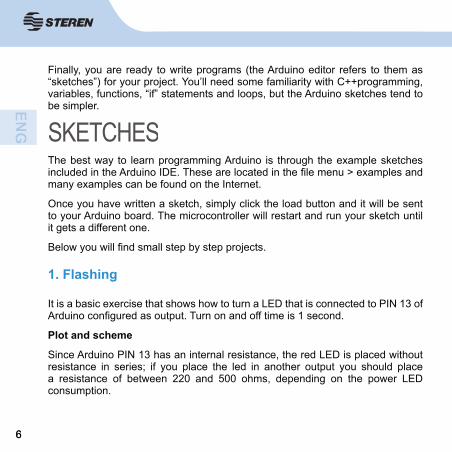
Finally, you are ready to write programs (the Arduino editor refers to them as “sketches”) for your project. You’ll need some familiarity with C++programming, variables, functions, “if” statements and loops, but the Arduino sketches tend to be simpler.
The best way to learn programming Arduino is through the example sketches included in the Arduino IDE. These are located in the fi le menu > examples and many examples can be found on the Internet.
Once you have written a sketch, simply click the load button and it will be sent to your Arduino board. The microcontroller will restart and run your sketch until it gets a different one.
Below you will fi nd small step by step projects.
It is a basic exercise that shows how to turn a LED that is connected to PIN 13 of Arduino confi gured as output. Turn on and off time is 1 second.
Plot and scheme
Since Arduino PIN 13 has an internal resistance, the red LED is placed without resistance in series; if you place the led in another output you should place a resistance of between 220 and 500 ohms, depending on the power LED consumption.
1. Flashing

77
The connection to be carried out in this case is to 10 PIN output.
IORE
FRE
SET
3V3
5V GND
GND
V1n
SCL
SDA
AREF
GND
13 12 11 10 9 8 7 6 5 4 3 2 1 0
A0 A1 A2 A3 A4 A5TX
1 1
AX1
0
POWER ANALOG IN
DIGIRAL (PWM)A11
A10
A9 A8 A7 A6
IORE
FRE
SET
3V3
5V GND
GND
V1n
SCL
SDA
AREF
GND
13 12 11 10 9 8 7 6 5 4 3 2 1 0
A0 A1 A2 A3 A4 A5TX
1 1
AX1
0
POWER ANALOG IN
DIGIRAL (PWM)A11
A10
A9 A8 A7 A6

88
Program
/** Intermittent** Basic example with Arduino. Switching on and off of a LED* with a cadence of 1 s using the 13 PIN as output* is not necessary to use a resistor for LED* exit 13 Arduino has it built-in.** http://www.arduino.cc/en/Tutorial/Blink*/int ledPin = 13; // Defi nition of the PIN 13 output void setup() //Confi guration{pinMode(ledPin, OUTPUT); // designates the PIN 13 digital output }void loop() // operating loop {digitalWrite(ledPin, HIGH); // activates the LEDdelay (1000); // 1 s wait (on-time)digitalWrite(ledPin, LOW); // disables the LEDdelay (1000); // 1 s wait (off-time)}

99
When you press the button (input 5 to ‘0’), output 13 turns on and shuts off intermittently.
How it works:
When the I5 = 1 then O13 = 0
When the I5 = 0 then O13 = 0-1 (intermittent 200,200 ms)
10 K
2. Alarm

1010
Program
int ledPin = 13; // choose the PIN for LEDint Nifne = 5; // choose the input pin (for a pushbutton) int val = 0; // variable for reading the pin status void setup() {pinMode(ledPin, OUTPUT); // declare LED as output pinMode(inPin, INPUT); // declare pushbutton as input }void loop() {val= digitalRead (Nifne); // reads input valueif(val== HIGH) { // check if the value read is “1” (button pressed) digitalWrite(ledPin, LOW); // set the LED to OFF} else{digitalWrite(ledPin, LOW); // the LED blinksdelay (200);digitalWrite (ledPin, HIGH);delay (200);}}

1111
It turns on and off 3 LEDs placed in the 6, 7 and 8 outputs (PIN 6 PIN 7 and PIN 8) with a cadence of 200 ms. Assigned to each LED are ledPin1, ledPin2 and ledPin3 variables.
3. Basic 3 LEDs sequence
8 76GND

1212
Program
Switching on and off of 3 LEDsint ledPin1 = 6; // Defi nes the LEDs outputsint ledPin2 = 7;int ledPin3 = 8;void setup() { // set the outputs pinMode(ledPin1, OUTPUT); // declare LEDs as outputspinMode(ledPin2, OUTPUT);pinMode(ledPin3, OUTPUT);digitalWrite(ledPin1, LOW); // Turn off the LEDsdigitalWrite (ledPin2, LOW);digitalWrite (ledPin3, LOW);}void loop() { //work loopdigitalWrite(ledPin1, HIGH); // turn off and on the LEDs lights every 200 msdelay (200);digitalWrite (ledPin1, LOW);digitalWrite (ledPin2, HIGH);delay (200);digitalWrite (ledPin2, LOW);digitalWrite (ledPin3, HIGH);delay (200);digitalWrite (ledPin3, LOW);}

1313
10 K
It counts the times a button connected to Arduino input 7 is pressed whenever we have we light the LED connected at output 13. The value of the variable that stores the number of pulses generated is sent to the PC so that it is displayed on the screen.
4. Counter

1414
Program counter/ * Detects if connected to the input jack 7 button has been pressed and LED lights up* Send the value of the variable ‘Counter’ account via serial port to the PC.***/int LED = 13;int Button = 7;int value = 0;int counter = 0;int buttonlaststate = 0;void setup(){Serial.begin(9600); // Confi gures transmission speed to 9600pinMode(LED, OUTPUT); // Initializes as a digital output pin 13pinMode(Boton, INPUT); // initializes as a digital input the 7digitalWrite(Boton,HIGH); // Enable internal resistance Pull-up from PIN7}void loop(){value = digitalRead(Boton); // Reads the digital input pin 7 valuedigitalWrite(LED, !valor); // Write in the output the read denied valueif(value != int buttonlaststate){if(value == 1){counter++;

1515
We could avoid the resistance placed at the button if the internal resistance of PIN7 is enabled, in this case the circuit would be as follows:
Serial.print(counter);Serial.write(10);Serial.write(13);}}int buttonlaststate = value;}

1616
The program in this case would be very similar to the previous. Note that now when the button is pressed we introduce an “=” at PIN7, therefore, if you want to start the PIN13 output, you should write in it the value read from the denied button, i.e. “!value”.
Modifi ed counter program
/ * Detects if connected to the input jack 7 button has been pressed and LED lights up* Send the value of the variable ‘Counter’ account via serial port to the PC.***/int LED = 13;int Button = 7;int value = 0;int counter = 0;int buttonlaststate = 0;void setup(){Serial.begin(9600); // Confi gures transmission speed to 9600pinMode(LED, OUTPUT); // Initializes as a digital output pin 13pinMode(Boton, INPUT); // Initializes as a digital input the 7digitalWrite(Button,HIGH); // Enable internal resistance Pull-up from PIN7}void loop(){

1717
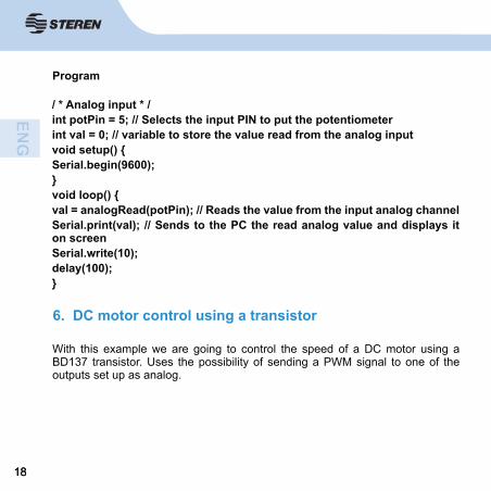
It set up the pin 5 as analog input and sends the read value to your PC to view it.
5. Analog input
valor = digitalRead(Button); // Reads the digital input pin 7 valuedigitalWrite(LED, !value); // (Write in the output the read denied valueif(value != int buttonlaststate){if(value == 1){counter++;Serial.print(counter);Serial.write(10);Serial.write(13);}}int buttonlaststate = value;}
1818
Program
With this example we are going to control the speed of a DC motor using a BD137 transistor. Uses the possibility of sending a PWM signal to one of the outputs set up as analog.
6. DC motor control using a transistor
/ * Analog input * /int potPin = 5; // Selects the input PIN to put the potentiometerint val = 0; // variable to store the value read from the analog inputvoid setup() {Serial.begin(9600);}void loop() {val = analogRead(potPin); // Reads the value from the input analog channelSerial.print(val); // Sends to the PC the read analog value and displays it on screenSerial.write(10);delay(100);}

1919
Please note that the motor must be low power for two reasons: fi rst because if we feed testing from USB connector must not pull too much current from the computer and second, because the transistor is current limited.
1N4001 diode is positioned as protection to prevent that the reverse currents created in the motor winding could damage the transistor.

2020
The tension that we are going to pull from outputt 10 (analog type PWM) will vary on way to ramp up and down cyclically. We get this effect with a structure for type:
for(value = 0; value <= 255; value +=5) (ascending)for(value = 255; value >=0; value-=5) (descending)
Note that increases in the voltage value range from 5 at 5 and we have to consider that 0v equals 0 and 5v is equivalent to 255.
Analog-value

2121
Installation variant: using a potentiometer as speed control.
To control the speed to our liking, i.e. using a potentiometer which is placed in one of the analog inputs and based on the value that is read at the input, so the motor rotates more or less fast.
Program
int value = 0; // a variable that contains the value to get analog input terminalint motor = 10; // motor connected to PIN 10void setup(){ // Not necessaryvoid loop(){for(value = 0; value <= 255; value +=5){//generates a ramp of voltage from 0 to 255, i.e. from 0 to 5vanalogWrite (motor, value);delay (30); // wait 30 ms to make the effect visible}for(value = 255; value >=0; value-=5){// a down ramp from 255 to 0 voltage is generated that is 5 to 0vanalogWrite (motor, value);delay (30);}}

2222
Program
int value = 0; // a variable that contains the value to get analog input readint motor = 10; // motor connected to PIN 10int potentiometer = 0 ; // Set the analogue inputvoid setup(){ // Not necessaryvoid loop(){value = analogRead (potentiometer); // reads the value of the analog inputand allocates valanalogWrite (motor, value); // The read value is sent to the analog output 0delay (30); // wait 30 ms to make visible the effect}

2323
With this application we will move a DC motor using a power IC, specifi c for these applications. The circuit you can move up to two motors, we’ll only do it with one.
In this Assembly, we can move the motor in both rotation directions, which we couldn’t with the previous assembly.
It will function as the fi rst approach of the previous motor, i.e., let’s create a power surge and a descent ramp so motor change speed in automatic mode.
DC motor control or driver:
The two parameters that we want to control of a DC motor is its speed and its rotation direction. The direction is controlled by changing the polarity. On the other hand, for its speed, we must use modulation technique for PWM-pulse width.
Here are some graphs showing the relationship between the pulse (PWM) signal and the effective voltage:
7. DC motor control using a L293D driver

2424
When the pulse is active is half of the period of the signal or duty cycle parameter is 50%, the effective voltage is half of the total input voltage.
When the duty cycle is reduced to 25%, the effective voltage is a quarter of the total input voltage. Then the motor speed decreases.
Thus, by controlling the duty cycle or while the pulse is active (frequency), we can control the DC motor speed.
A way to perform this check on Arduino, is using the PWM analog output.
You should remembered that the PWM output signal (pins 9, 10) is a constant frequency signal (30769 Hz) and that only allows us to change the “duty cycle” or the time that the pulse is active (on) or inactive (off), using the analogWrite() function.

2525
The other way is generating PWM signals using the microprocessor capability through the function digitalWrite ().
If you want to simultaneously control the speed and direction of a motor, we need to use an integrated circuit or chip, called in general, as “ H bridge “, for example the L293D.Chip L293D/B (H-bridge):
It is an integrated circuit or chip that can be used to simultaneously control the speed and direction of two DC motors (containing two H bridges). The difference between L393D and L293B model is that the fi rst comes with protection diodes which avoid damage caused by the voltage spikes that the motor can cause.
It contains 4 digital pins (2, 7, 10, 15) to control the motor direction.

2626
The “enable” (1, 9) pins support as input a PWM signal and it are used to control the speed of the motors using pulse width modulation technique.
The motors are connected between pins 3, 6, 11 or 14. The Vss voltage is to feed or give power to the motor.
Basic installation: Simple Control of an motor with the L293 CI at constant speed
First we will just show the speed of a DC motor control through the L293D integrated. So we set the direction control PIN to 5v and 0v, in such a way that it will only turn in one direction. If we want to change direction, it will only be necessary to change the polarization.
Program
Simple control of an motor with the L293 CI at constant speedint motorpin = 10; // Output analog PWM PIN void setup(){}void loop() {analogWrite(motorpin, 125); // activates the motor at a constant speeddelay (100); // wait 100 ms for the next reading}

2727
8. Motor control: variable speed and variable rotation
IOREF
RESET
3V3
5V GND VIN 0 1 2 3 4 5 6 7 8 9 10 11 12 13 14 15
DIGITAL
AREF GND 13 12 11 10 9 8
TXD3
14
RXD3
15
TXD2
16
RXD2
17
TXD1
18
RXD2
17
SDA
20
SCL
21
COMMUNICATION
PWM
POWER ANALOG IN
7 6 5 4 3 2 1 0 22
24
26
28
30
32
34
36
38
40
42
44
46
48
50
52

2828
Program
Motor control with L293D driver int value = 0; // a variable that contains the valueint motorFowards = 10; // Motor forward - > PIN 10int motorBackwards = 11; // Motor recoil - > PIN 11void setup() {} // Not necessaryvoid loop() {analogWrite(motorBackwards, 0); // Motor forward... raises the speedfor(value = 0; value <= 255; value+=5) {analogWrite (motorFowards, value);delay (30);}for(value = 255; value >=0; value-=5) { // forward motor... lowers the speedanalogWrite (motorFowards, value);delay (30);}analogWrite(motorFowards, 0); // Motor back... raises the speedfor(value = 0; value <= 255; value+=5) {analogWrite (motor motorBackwards, value);delay (30);}for(value = 255; value >=0; value-=5) { // motor backwards... lowers speed }analogWrite (motorBackwards, value);delay (30);}}

2929
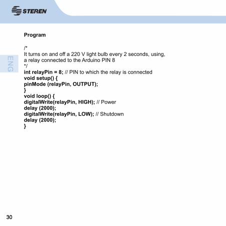
This example shows how to power a 120-Volt alternating current (AC) light bulb through a circuit of 5 V DC (DC) ruled by the Arduino. It can be used with any other circuit of 120 V, with a maximum of 10 A (with the relay of the example).What is a relay?The relay is an electromechanical device that functions as a switch controlled by an electrical circuit in which, by means of an electromagnet, actuates a set of one or more contacts that allow open or close other independent electrical circuits.From here extract important information: we can separate two circuits in such a way that they work with different voltages. One to 5 V (Arduino) and another 120 v (the bulb).
9. Use a relay to turn on 120 V devices
As shown in the diagram below, there are two circuits. Black wiring operates at 5 V DC and the red one at 120V AC.
3030
Program
/*It turns on and off a 220 V light bulb every 2 seconds, using,a relay connected to the Arduino PIN 8*/int relayPin = 8; // PIN to which the relay is connected void setup() {pinMode (relayPin, OUTPUT);}void loop() {digitalWrite(relayPin, HIGH); // Powerdelay (2000);digitalWrite(relayPin, LOW); // Shutdowndelay (2000);}
3131
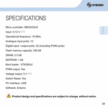
Product design and specifi cations are subject to change, without notice.
SPECIFICATIONSMicro controller: MEGA32U4
Input: 5-12 V - - -
Operational frequency: 16 MHz
Analogue input ports: 12
Digital input / output ports: 20 (including PWM ports)
Flash memory capacity: 256 kB
SRAM: 2.5 kB
EEPROM: 1 kB
Boot loader: STK500v2
PWM output: Yes
Voltage output: 5 V - - -
Switch Reset: Yes
PC interface: USB
Software: Arduino

3232
WARRANTY
This Steren product is warranted under normal usage against defects in workmanship and materials to the original purchaser for one year from the date of purchase.
CONDITIONS
1. This warranty card with all the required information, invoice, product box or package, and product, must be presented when warranty service is required.2. If the product is in the warranty time, the company will repair it free of charge.3. The repairing time will not exceed 30 natural days, from the day the claim was received.4. Steren sell parts, components, consumables and accessories to customer, as well as warranty service, at any of the addresses mentioned later.
THIS WARRANTY IS VOID IN THE NEXT CASES:
If the product has been damaged by an accident, acts of God, mishandling, leaky batteries, failure to follow enclosed instructions, improper repair by unauthorized personnel, improper safe keeping, among others.
a) The consumer can also claim the warranty service in the purchase establishment.b) If you lose the warranty card, we can reissue it, if you show the invoice or purchase ticket.
RETAILER INFORMATIONName of the retailerAddressProductBrandPart numberSerial numberDate of delivery
Product: PCB compatible with Arduino LeonardoPart number: ARD-020Brand: Steren
In case your product fails or have questions, please
contact your nearest dealer. If you are in Mexico, please
call to our Call Center.
01 800 500 9000