FUNCT IONAL F E A TURES - telefonia y seguridad
24
1 ARMADURA Disponible en múltiples versiones: sólo picaporte, picaporte y cerrojo, plana o en ángulo, para embutir y sobreponer. Para la integración con cerramientos en aluminio, hierro y madera se pueden fabricar en alu- minio, acero y acero inoxidable. Para cada tipo de material existe un amplia gama de acabados disponi- bles ( Pinturas, anodizados, Cromos, Latones, cueros , brillos, mates, satinados etc.…) 2 AUTOMÁTICO (A) Este mecanismo detecta el alineamiento de la puerta con el marco y al recibir un único y breve impulso eléctrico mantiene el mecanismo en estado de desac- tivación (permite abrir la puerta), en contraposición a los automáticos internos que pueden dejar la puerta abierta sin que el usuario lo sepa. En el caso de los abrepuertas ASSEL si la puerta no está cerrada, el automático no actúa . El abrepuertas se rearma cuan- do se cruza el umbral y se cierra la puerta, quedan- do preparado para otra apertura en cuanto se requie- ra.. 3 DESBLOQUEO MECÁNICO (D) También llamado "función portero de día". La palan- ca de desbloqueo inhibe el funcionamiento del abre- puertas, permitiendo el libre acceso al local. El pesti- llo está liberado, y la puerta puede ser abierta o cerrada sin ningún impedimento. Fabricado en fibra de nylon, material que resiste de sobra el rozamien- to con los mecanismos internos durante toda la vida media del aparato. Para mantener el cerramiento en posición de clausura, cuando está activado el desblo- queo mecánico, se aconseja la instalación de un cie- rrapuertas hidráulico para evitar la acción del viento. 4 REGLETA DE CONEXIÓN Los abrepuertas ASSEL pueden servirse con diferen- tes tipos de regleta de conexiones: integrada (embu- tida dentro del cuerpo del abrepuertas, que lo dota de mayor protección contra contactos indebidos) o estándar (exterior al cuerpo del aparato y de fácil manipulación). La serie 80 va dotada de una regleta reforzada contra manipulación indebida con un circui- to impreso presoldado. 5 MICRORRUPTOR (M) Este mecanismo, garantizado por 500.000 ciclos mecánicos, dota al abrepuertas de la posibilidad de monitorizar el estado de la puerta (abierta o cerrada), conectándolo a un sistema semafórico. También per- mite el interbloqueo de dos puertas, haciendo pasar el circuito de estimulación del primero por el del segundo y viceversa, utilizando el microinterruptor de dos posiciones como condición indispensable de activación. 6 DESBLOQUEO ELÉCTRICO (EU) Los abrepuertas de ASSEL se pueden servir con bobi- nas de corriente continua de 12 ó 24 Voltios, diseña- das y preparadas especialmente para estar conecta- das todo el día (continuamente conectados). Lo que unido a una fuente regulada de corriente continua con temporización o un interruptor convierte estos aparatos en un valioso dispositivo de control de accesos, pudiéndose conectar directamente a conso- las de control o a sistemas de tarjeta magnética y teclado. Pueden servirse en dos versiones: Acción invertida (la estimulación eléctrica bloquea el apara- to y la puerta permanece cerrada) o continuamente conectado (la estimulación eléctrica libera el meca- nismo y la puerta permanece abierta mientras dure la estimulación). 7 PESTILLO REGULABLE (E) Permite el ajuste preciso y rápido en el momento de la primera instalación. El posible asentamiento de los cerramientos, así como la posible dilatación térmica puede ser compensada por el ajuste de 1 a 4 mm, gracias a los tornillos de regulación del pestillo. 1 FACEPLATE A wide range of different faceplates is available: mor- tice and rim short or sashlock faceplates, flat or angled-shaped; aluminium, steel or stainless-steel made in up to 19 different finishes varing from the commonly used silver coating to the latest and newest platings (polished, matt or satin brass, chrome or nic- kel) 2 ONE-SHOT RELEASE PIN (A) This pin, located in the centre of the latchbolt, detects the correct alignement between the door and the frame. When energized (AC FailSecure models only) it allows a free entry by keeping the strike in a deactiva- ted position. On shutting the door the strike gets re- armed, turning the door into a secured position and allowing for a new opening whenever it should be required. ASSEL’s one-shot release pin doesn´t actuate while the door is kept open. Thus, undesirable ope- nings are avoided. Care should be taken when specif- ying this function as some strikes featuring built-insi- de, invisible one-shot releasing devices can not assu- re this. 3 MECHANICAL UNLATCHING (D) It lets (AC versions only) a free-entry outside of con- trolled periods by means of a mechanical lever that keeps the strike in a permanent deactivated state. Lever made of nylon for lifetime trouble-free operation. In order to prevent unintentional openings when the unlatching lever is actuated (due to the action of the wind, draughts, etc.), a suitable door-closer should be fitted to the door. 4 TERMINAL Our strikes are supplied with different terminals: built- in terminals (like the one shown in the picture) that provide an extra-protection to the strike against unproper contacts or easy-access external terminals. Our heavy-duty range (Serie 80) features a reinforced printed-circuit isolated and pre-weld connection termi- nal as a standard. 5 MICROSWITCH (M) 500.000 mechanical operating cycles guaranteed, this device allows the monitoring of the door state (open or closed) from inside by connecting the strike into a traffic-light or a computer-based monitoring system. It can also be used with interlocking doors for high-secu- rity access (eg. bank lobbies) 6 ELECTRICAL UNLATCHING (EU) ASSEL electric strikes can be supplied with 12VDC or 24VDC continuous operating coils. When used in con- juction with a timer-included Power Supply Unit (PSU) a reliable access control device can be achieved. Card- readers, keypads and controlled switching panels can be incorporated. DC continuous strikes are available in two different duty versions: FAILSAFE or (DC conti- nuous) FAIL-SECURE. 7 ADJUSTABLE LATCH (E) Enables fast and accurate 1 to 4 mm site adjustment of the latch, to overcome problems such as thermal bowing of doors. E L E M E N T O S FUNCIONALES F U N C T I O N A L F E A T U R E S 1 2 3 4 5 6 7 06.E.AD.T.11.1.I Desplegar solapa Unfold Flap Desplegar solapa Unfold Flap
Transcript of FUNCT IONAL F E A TURES - telefonia y seguridad
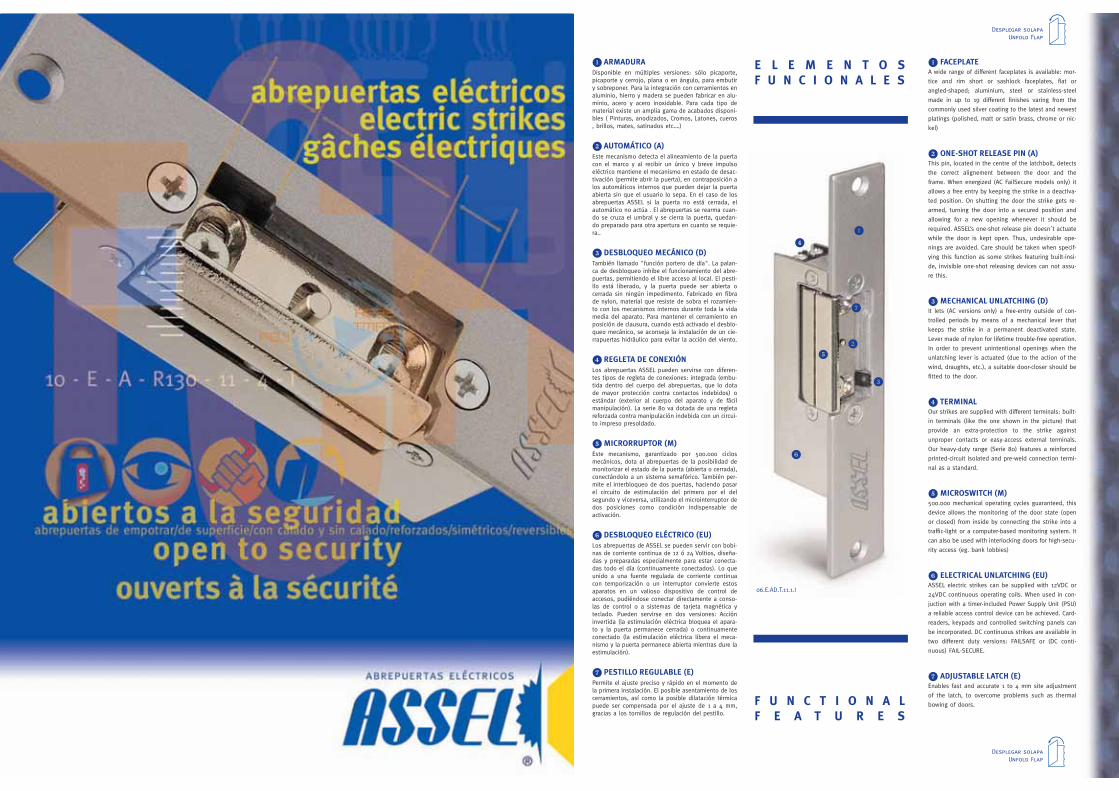
1 ARMADURADisponible en múltiples versiones: sólo picaporte,picaporte y cerrojo, plana o en ángulo, para embutiry sobreponer. Para la integración con cerramientos enaluminio, hierro y madera se pueden fabricar en alu-minio, acero y acero inoxidable. Para cada tipo dematerial existe un amplia gama de acabados disponi-bles ( Pinturas, anodizados, Cromos, Latones, cueros, brillos, mates, satinados etc.…)
2 AUTOMÁTICO (A)Este mecanismo detecta el alineamiento de la puertacon el marco y al recibir un único y breve impulsoeléctrico mantiene el mecanismo en estado de desac-tivación (permite abrir la puerta), en contraposición alos automáticos internos que pueden dejar la puertaabierta sin que el usuario lo sepa. En el caso de losabrepuertas ASSEL si la puerta no está cerrada, elautomático no actúa . El abrepuertas se rearma cuan-do se cruza el umbral y se cierra la puerta, quedan-do preparado para otra apertura en cuanto se requie-ra..
3 DESBLOQUEO MECÁNICO (D)También llamado "función portero de día". La palan-ca de desbloqueo inhibe el funcionamiento del abre-puertas, permitiendo el libre acceso al local. El pesti-llo está liberado, y la puerta puede ser abierta ocerrada sin ningún impedimento. Fabricado en fibrade nylon, material que resiste de sobra el rozamien-to con los mecanismos internos durante toda la vidamedia del aparato. Para mantener el cerramiento enposición de clausura, cuando está activado el desblo-queo mecánico, se aconseja la instalación de un cie-rrapuertas hidráulico para evitar la acción del viento.
4 REGLETA DE CONEXIÓNLos abrepuertas ASSEL pueden servirse con diferen-tes tipos de regleta de conexiones: integrada (embu-tida dentro del cuerpo del abrepuertas, que lo dotade mayor protección contra contactos indebidos) oestándar (exterior al cuerpo del aparato y de fácilmanipulación). La serie 80 va dotada de una regletareforzada contra manipulación indebida con un circui-to impreso presoldado.
5MICRORRUPTOR (M)Este mecanismo, garantizado por 500.000 ciclosmecánicos, dota al abrepuertas de la posibilidad demonitorizar el estado de la puerta (abierta o cerrada),conectándolo a un sistema semafórico. También per-mite el interbloqueo de dos puertas, haciendo pasarel circuito de estimulación del primero por el delsegundo y viceversa, utilizando el microinterruptor dedos posiciones como condición indispensable deactivación.
6 DESBLOQUEO ELÉCTRICO (EU)Los abrepuertas de ASSEL se pueden servir con bobi-nas de corriente continua de 12 ó 24 Voltios, diseña-das y preparadas especialmente para estar conecta-das todo el día (continuamente conectados). Lo queunido a una fuente regulada de corriente continuacon temporización o un interruptor convierte estosaparatos en un valioso dispositivo de control deaccesos, pudiéndose conectar directamente a conso-las de control o a sistemas de tarjeta magnética yteclado. Pueden servirse en dos versiones: Accióninvertida (la estimulación eléctrica bloquea el apara-to y la puerta permanece cerrada) o continuamenteconectado (la estimulación eléctrica libera el meca-nismo y la puerta permanece abierta mientras dure laestimulación).
7 PESTILLO REGULABLE (E)Permite el ajuste preciso y rápido en el momento dela primera instalación. El posible asentamiento de loscerramientos, así como la posible dilatación térmicapuede ser compensada por el ajuste de 1 a 4 mm,gracias a los tornillos de regulación del pestillo.
1 FACEPLATEA wide range of different faceplates is available: mor-
tice and rim short or sashlock faceplates, flat or
angled-shaped; aluminium, steel or stainless-steel
made in up to 19 different finishes varing from the
commonly used silver coating to the latest and newest
platings (polished, matt or satin brass, chrome or nic-
kel)
2 ONE-SHOT RELEASE PIN (A)This pin, located in the centre of the latchbolt, detects
the correct alignement between the door and the
frame. When energized (AC FailSecure models only) it
allows a free entry by keeping the strike in a deactiva-
ted position. On shutting the door the strike gets re-
armed, turning the door into a secured position and
allowing for a new opening whenever it should be
required. ASSEL’s one-shot release pin doesn´t actuate
while the door is kept open. Thus, undesirable ope-
nings are avoided. Care should be taken when specif-
ying this function as some strikes featuring built-insi-
de, invisible one-shot releasing devices can not assu-
re this.
3MECHANICAL UNLATCHING (D)It lets (AC versions only) a free-entry outside of con-
trolled periods by means of a mechanical lever that
keeps the strike in a permanent deactivated state.
Lever made of nylon for lifetime trouble-free operation.
In order to prevent unintentional openings when the
unlatching lever is actuated (due to the action of the
wind, draughts, etc.), a suitable door-closer should be
fitted to the door.
4 TERMINALOur strikes are supplied with different terminals: built-
in terminals (like the one shown in the picture) that
provide an extra-protection to the strike against
unproper contacts or easy-access external terminals.
Our heavy-duty range (Serie 80) features a reinforced
printed-circuit isolated and pre-weld connection termi-
nal as a standard.
5MICROSWITCH (M)500.000 mechanical operating cycles guaranteed, this
device allows the monitoring of the door state (open
or closed) from inside by connecting the strike into a
traffic-light or a computer-based monitoring system. It
can also be used with interlocking doors for high-secu-
rity access (eg. bank lobbies)
6 ELECTRICAL UNLATCHING (EU)ASSEL electric strikes can be supplied with 12VDC or
24VDC continuous operating coils. When used in con-
juction with a timer-included Power Supply Unit (PSU)
a reliable access control device can be achieved. Card-
readers, keypads and controlled switching panels can
be incorporated. DC continuous strikes are available in
two different duty versions: FAILSAFE or (DC conti-
nuous) FAIL-SECURE.
7 ADJUSTABLE LATCH (E)Enables fast and accurate 1 to 4 mm site adjustment
of the latch, to overcome problems such as thermal
bowing of doors.
E L E M E N T O SF U N C I O N A L E S
F U N C T I O N A LF E A T U R E S
1
2
3
4
5
6
7
06.E.AD.T.11.1.I
Desplegar solapaUnfold Flap
Desplegar solapaUnfold Flap
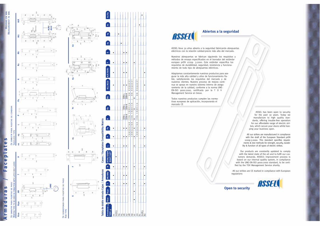
ASSEL lleva 30 años abierto a la seguridad fabricando abrepuertaseléctricos con la relación calidad-precio más alta del mercado.
Nuestros abrepuertas se fabrican siguiendo los requisitos ymétodos de ensayo especificados en el borrador del estándareuropeo prEN 12209- 3:2000. Este estándar especifica losrequisitos de durabilidad, seguridad, resistencia y funciona-miento de todo tipo de abrepuertas eléctricos.
Adaptamos constantemente nuestros productos para ase-gurar la más alta calidad y años de funcionamiento fia-ble, satisfaciendo los requisitos del mercado y denuestros clientes. Nuestro proceso de mejora conti-nua se apoya en nuestro sistema interno de asegu-ramiento de la calidad, conforme a la norma UNE-EN-ISO 9000:2000, certificado por la T Ü VManagement Service en breve.
Todos nuestros productos cumplen las norma-tivas europeas de aplicación, incorporando elmarcado CE
ASSEL has been open to securityfor the past 30 years. Today we
manufacture to high quality stan-dards, offering trouble-free operation
for our affordable range of electric stri-kes, which secure your doors whilst kee-
ping your business open.
All our strikes are manufactured in compliancewith the draft of the European Standard prEN
12209-3:2000. This standard specifies require-ments & test methods for strength, security, durabi-
lity & function of all types of electric strikes.
Our products are constantly updated to complywith the latest state of the art and to fulfil our cus-
tomers demands. ASSEL’s improvement process isbased on our internal quality system, in compliance
with the UNE-EN-ISO 9000:2000 standard, to be certi-fied by the TÜV Management Service shortly.
All our strikes are CE marked in compliance with Europeanregulations
Abiertos a la seguridad
Open to security
110
33 44 33
25
130
43 44 43
25
250
4464
25
102
14,5
12
17
107
19 25 44 38 19
37
145
74
12
250
4464
25
40
61
250
4464
17
17
25
91
17
250
4464 17
160
44 6650
25
22
25 44 39
108
3350
64
10
44 40 74 28
250
109
2532
1515 105
(Ser
ie01
)90
(Ser
ie06
,07)
12
15
10 2532
142
54 44 64
172
10
R11
0
SF
R13
0T
AN
AN
U
LH
0203
RR
2R
GA
LLA
LR
64 44
250
40 74 2810
10 25329
15
1) ,07)15
12
250
4464
25
ALR
UA
LLU
105
(STD
01)
90 (AJU
ST06
/07)
108
4563
,5
35
83,
512
,7
41 41 12,7
25,7 52
30,5
51,7
25,3
22010
5
90,8
24,3
43 61
1721
12
61
250
4464
17
17
7
47 80
5 5,5
14
91
250
4465
2519
16
17
62
44
36,4
7
53
195,
5
7010 28948
8
112
4646
5,5
26,5
10
12
24
131
6251
624820
62
4436,4
7
53
195,
5 7010 2894
8
8
112
4646
5,5
26,5
10
PP
2
0563
6162
Arm
ad
ura
s/
Fa
ce
pla
tes
Med
idas
enm
m.
Mea
sure
men
tin
mm
.De
embu
tir
para
puer
tas
depa
soM
ortise
type
tobe
used
inco
njuc
tion
with
latc
hbo
ltlo
cks
De
embu
tir
para
puer
tas
deco
nden
aSa
shlo
ckty
pe
De
sobr
epone
rpa
rapu
erta
sde
paso
Rim
type
Tabl
ade
dobl
een
trad
aCa
jas
/A
rmad
uras
Case
s/
Face
plat
esCo
mpa
tibi
lity
Mat
rix
Arm
adur
asR
110
R13
0T
AN
/AN
UH
DCH
A/I
ZQD
AL
PP
2R
R2
RG
ALL
/ALL
UA
LR/A
LRU
FS
0504
6162
/63
Caja
sR
IGH
T/LE
FT
01•
••
••
••
••
•02
/03
•04
•05
•06
••
••
••
DIN
-LDIN
-LDIN
-L•
••
•07
••
••
••
DIN
-RDIN
-RDIN
-R•
••
•08
CO
NS
UL
TA
RC
ON
FÁ
BR
IC
A/
ON
RE
QU
ES
T
09C
ON
SU
LT
AR
CO
NF
ÁB
RIC
A/
ON
RE
QU
ES
T
10•
••
••
••
••
••
20C
ON
SU
LT
AR
CO
NF
ÁB
RIC
A/
ON
RE
QU
ES
T
61•
62/6
3•
80•
••
••
••
•
➔➔
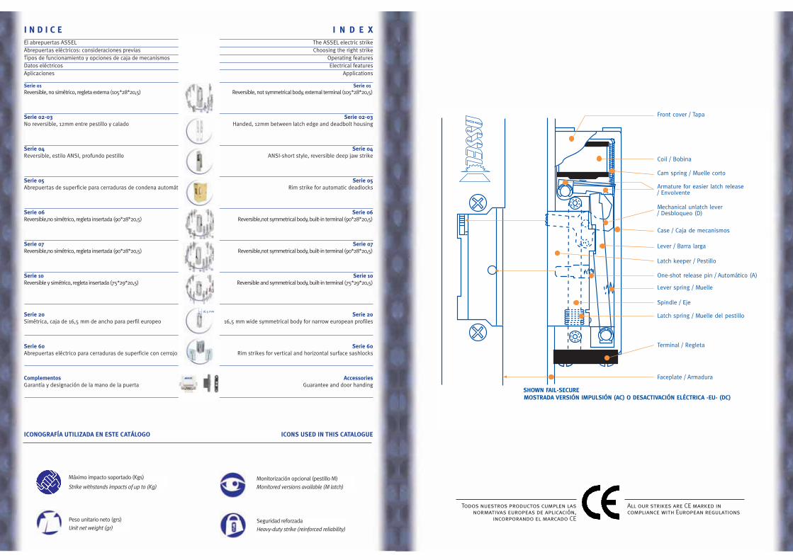
Front cover / Tapa
SHOWN FAIL-SECURE
Terminal / Regleta
Latch spring / Muelle del pestillo
Spindle / Eje
Lever spring / Muelle
One-shot release pin / Automático (A)
Latch keeper / Pestillo
Mechanical unlatch lever/ Desbloqueo (D)
Armature for easier latch release/ Envolvente
Cam spring / Muelle corto
Coil / Bobina
Case / Caja de mecanismos
Faceplate / Armadura
Lever / Barra larga
MOSTRADA VERSIÓN IMPULSIÓN (AC) O DESACTIVACIÓN ELÉCTRICA -EU- (DC)
Todos nuestros productos cumplen lasnormativas europeas de aplicación,
incorporando el marcado CE
All our strikes are CE marked incompliance with European regulations
I N D I C E I N D E XEl abrepuertas ASSEL The ASSEL electric strikeAbrepuertas eléctricos: consideraciones previas Choosing the right strikeTipos de funcionamiento y opciones de caja de mecanismos Operating featuresDatos eléctricos Electrical featuresAplicaciones Applications
Serie 01 Serie 01Reversible, no simétrico, regleta externa (105*28*20,5) Reversible, not symmetrical body, external terminal (105*28*20,5)
Serie 02-03 Serie 02-03No reversible, 12mm entre pestillo y calado Handed, 12mm between latch edge and deadbolt housing
Serie 04 Serie 04Reversible, estilo ANSI, profundo pestillo ANSI-short style, reversible deep jaw strike
Serie 05 Serie 05Abrepuertas de superficie para cerraduras de condena automática Rim strike for automatic deadlocks
Serie 06 Serie 06Reversible,no simétrico, regleta insertada (90*28*20,5) Reversible,not symmetrical body, built-in terminal (90*28*20,5)
Serie 07 Serie 07Reversible,no simétrico, regleta insertada (90*28*20,5) Reversible,not symmetrical body, built-in terminal (90*28*20,5)
Serie 10 Serie 10Reversible y simétrico, regleta insertada (75*29*20,5) Reversible and symmetrical body, built-in terminal (75*29*20,5)
Serie 20 Serie 20Simétrica, caja de 16,5 mm de ancho para perfil europeo 16,5 mm wide symmetrical body for narrow european profiles
Serie 60 Serie 60Abrepuertas eléctrico para cerraduras de superficie con cerrojo Rim strikes for vertical and horizontal surface sashlocks
Complementos AccessoriesGarantía y designación de la mano de la puerta Guarantee and door handing
ICONOGRAFÍA UTILIZADA EN ESTE CATÁLOGO ICONS USED IN THIS CATALOGUE
16,5 mm
Máximo impacto soportado (Kgs)
Strike withstands impacts of up to (Kg)
Peso unitario neto (grs)
Unit net weight (gr)
Monitorización opcional (pestillo M)
Monitored versions available (M latch)
Seguridad reforzada
Heavy-duty strike (reinforced reliability)
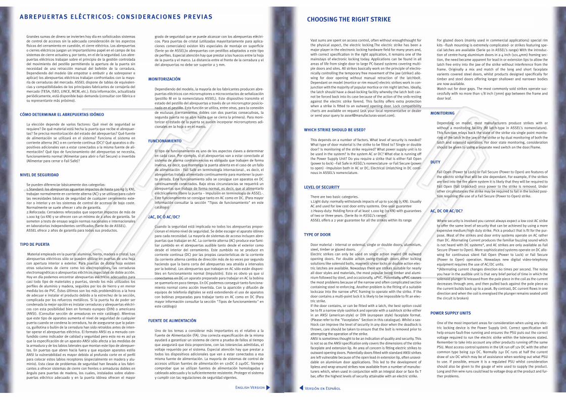
Vast sums are spent on access control, often without enoughthought forthe physical aspect, the electric locking.The electric strike has been amajor player in the electronic locking hardware field for many years and,with correct specification in the right application, it remains one of themainstays of electronic locking today. Applications can be found in allareas of life from single door to large PC-based systems covering multi-ple doors and sites. All strikes basically work on the principle of electro-nically controlling the temporary free movement of the jaw (striker) allo-wing for door opening without manual retraction of the latchbolt.Dependant on model (mortice or rim mount) electric strikes work in con-junction with the majority of popular mortice or rim night latches. Ideally,the latch should have a dead-locking facility whereby the latch bolt can-not be forced back into its case because of the action of the snib restingagainst the electric strike forend. This facility offers extra protectionwhen a strike is fitted to an outward opening door. Lock compatibilitycharts are available on request (ask your local representative or dealeror send your query to [email protected]).
WHICH STRIKE SHOULD BE USED?
This depends on a number of factors. What level of security is needed?What type of door material is the strike to be fitted to? Single or doubledoor? Is monitoring of the strike required? What power supply unit is tobe used in the system? Is the system AC or DC? What else is running offthe Power Supply Unit? Do you require a strike that is either Fail Open(power to lock) –Fail Safe in ASSEL’s nomenclature- or Fail Secure (powerto open) –Impulsion both in AC or DC; Electrical Unlatching in DC conti-nous in ASSEL’s nomenclature.
LEVEL OF SECURITY
There are two basic categories. 1.Light duty: normally withstands impacts of up to 500 kg (5 KN). UsuallyAC and used for low cost door entry systems. One-year guarantee 2.Heavy-duty: Holding force of at least 1.000 kg (10 KN) with guaranteesof two or three years. (Serie 80 in ASSEL’s range).ASSEL offers a 2 year guarantee for all the strikes within its range
TYPE OF DOOR
Door material - internal or external, single or double doors, aluminium,steel, timber or glazed doors.Electric strikes can only be used on single action inward OR outwardopening doors. For double action swing-through doors other lockingsolutions like solenoid bolts, magnetic shear locks or double action elec-tric latches are available. Nowadays there are strikes suitable for nearlyall door styles and materials, the most popular being timber and alumi-nium followed by steel, and occasionally, uPVC. Potentially, uPVC causesthe most problems because of the narrow and often complicated sectioncontaining steel re-enforcing. Another problem is the fitting of a suitablelockcase into the narrow uPVC framing to operate with the strike. If thedoor contains a multi-point lock it is likely to be impossible to fit an elec-tric strike. If the door contains, or can be fitted with a latch, the best option couldbe to fit a narrow style sashlock and operate with a sashlock strike eitherin an ANSI (american-style) or DIN (european style) faceplate format.(Please refer to the "Faceplates" Section in this catalogue). Whilst a sas-hlock can improve the level of security in any door when the deadlock isthrown, care should be taken to ensure that the bolt is removed prior toattempting the operation of the strike. ANSI is sometimes thought to be an indication of quality and security. Thisis not so as the ANSI specification only covers the dimensions of the strikefaceplate and extension lip. An area of concern is fitting electric strikes tooutward opening doors. Potentially doors fitted with standard ANSI strikesare left vulnerable because of the open lead-in extension lip, often unavoi-dable on aluminium door applications. This led to the development oflipless and wrap-around strikes now available from a number of manufac-turers which, when used in conjunction with an integral door or face fix Tbar, offer the highest levels of security attainable with an electric strike.
For glazed doors (mainly used in commercial applications) special rimkits –flush mounting is extremely complicated- or strikes featuring spe-cial latches are available (Serie 90 in ASSEL’s range) With the introduc-tion of centre-hung aluminium doors in a 4 inch (101.4mm) framing sec-tion, the need became apparent for lead in or extension lips to allow thelatch free entry into the jaw of the strike without interference from theframe. Originally a mix and match of the long and short faceplatevarients covered steel doors, whilst products designed specifically fortimber and steel doors offering longer shallower and narrower bodiesare now available. Watch out for door gaps. The most commonly sold strikes operate suc-cessfully with no more than 1/8 inch (3mm) gap between the frame anddoor leaf.
MONITORING
Depending on model, most manufacturers produce strikes with orwithout a monitoring facility (M latch-type in ASSEL’s nomenclature).This function relays back the state of the strike via single point monito-ring of the latch in the jaw of the strike or by dual monitoring of both thelatch and solenoid operation. For door state monitoring, considerationshould be given to using a separate reed switch on the door/frame.
DUTY
Fail Open (Power to Lock) or Fail Secure (Power to Open) are features ofthe electric strike that will be site dependant. For example, if the strikesare tied into the fire alarm system it is likely that they will be required toFail Open (Fail Unlocked) once power to the strike is removed. Underother circumstances the strike may be required to fail in the locked posi-tion requiring the use of a Fail Secure (Power to Open) strike.
AC, DC OR AC/DC?
Where security is involved you cannot always expect a low cost AC striketo offer the same level of security that can be achieved by using a moreexpensive medium/high duty strike. Pick a product that is fit for the pur-pose. Most of the strikes and door entry systems operate on AC ratherthan DC. Alternating Current produces the familiar buzzing sound whichis not heard with DC systems*, and AC strikes are only available as FailSecure (Power to Open). More sophisticated systems operate on DC allo-wing for continuous silent Fail Open (Power to Lock) or Fail Secure(Power to Open) operation. Nowadays new digital video-telephonyequipment requires the use of AC/DC units. *(Alternating current changes direction 60 times per second. The noiseyou hear in the audible unit is that very brief period of time in which thesolenoid plunger is released from the pole piece in the coil as the currentdecreases through zero, and then pulled back against the pole piece asthe current builds back up to a peak. By contrast, DC current flows in onedirection and when the coil is energised the plunger remains seated untilthe circuit is broken)
POWER SUPPLY UNITS
One of the most important areas for consideration when using any elec-tric locking device is the Power Supply Unit. Correct specification willhelp ensure fault-free running and ensures the PSU puts out the correctvoltage required to run the electric strike within the tolerances stated.Remember to take into account any other products running off the samePSU. Most access control systems in the UK run off 12v DC with the othercommon type being 24v DC. Normally 24v DC runs at half the currentdraw of 12v DC which may be of assistance when working out what PSUto use. If possible, ensure it is a regulated PSU whilst considerationshould also be given to the gauge of wire used to supply the product.Long and thin wire runs could lead to voltage drop at the product and fur-ther problems.
CHOOSING THE RIGHT STRIKE
Versión en Español
Grandes sumas de dinero se invierten hoy día en sofisticados sistemasde control de accesos sin la adecuada consideración de los aspectosfísicos del cerramiento en cuestión, el cierre eléctrico. Los abrepuertaso cierres eléctricos juegan un importantísimo papel en el campo de lossistemas de cierre actuales y, por tanto, en el de la seguridad. Los abre-puertas eléctricos trabajan sobre el principio de la gestión controladadel movimiento del pestillo permitiendo la apertura de la puerta sinnecesidad de una retracción manual del bofetón de la cerradura.Dependiendo del modelo (de empotrar o embutir y de sobreponer oaplicar) los abrepuertas eléctricos trabajan confrontados con la mayo-ría de cerraduras del mercado. ASSEL dispone de tablas de equivalen-cias y compatibilidades de los principales fabricantes de cerrajería delmercado (TESA, ISEO, LINCE, MCM, etc.). Esta información, actualizadaperiódicamente, está disponible bajo demanda (consultar con fábrica osu representante más próximo).
CÓMO DETERMINAR EL ABREPUERTAS IDÓNEO
La elección depende de varios factores: Qué nivel de seguridad serequiere? De qué material está hecha la puerta que recibe el abrepuer-tas? Se precisa monitorización del estado del abrepuertas? Qué fuentede alimentación se utilizará en el sistema? Funciona el sistema encorriente alterna (AC) o en corriente continua (DC)? Qué aparatos o dis-positivos adicionales van a estar conectados a la misma fuente de ali-mentación? Qué tipo de funcionamiento del abrepuertas se necesita,funcionamiento normal (Alimentar para abrir o Fail Secure) o invertido(Alimentar para cerrar o Fail Safe)?
NIVEL DE SEGURIDAD
Se pueden diferenciar básicamente dos categorías:1.Standard: los abrepuertas aguantan impactos de hasta 500 kg (5 KN),trabajan normalmente en corriente alterna (AC) y se utilizan para cubrirlas necesidades básicas de seguridad de cualquier cerramiento exte-rior o interior y en los sistemas de control de accesos de bajo coste.Normalmente se suele ofrecer 1 año de garantía.2.Reforzada: Cerraderos reforzados que soportan impactos de más de1.000 kg (10 KN) y se ofrecen con un mínimo de 2 años de garantía. Sesometen a tests de ensayo según normas nacionales e internacionalesen laboratorios independientes certificados (Serie 80 de ASSEL). ASSEL ofrece 2 años de garantía para todos sus productos.
TIPO DE PUERTA
Material empleado en la puerta: aluminio, hierro, madera o cristal. Losabrepuertas eléctricos sólo se pueden utilizar en puertas de una hojacon apertura interior o exterior. Para puertas de doble hoja existenotras soluciones de cierre como los electropistones, las cerraduraselectromagnéticas o abrepuertas eléctricos especiales de doble acción.Hoy en día podemos encontrar abrepuertas eléctricos adecuados paracasi todo tipo de materiales y puertas, siendo los más utilizados losperfiles de aluminio y madera, seguidos por los de hierro y en menormedida los de PVC. Éstos últimos son los más problemáticos a la horade adecuar e instalar el producto debido a la estrechez de la sección,complicada por los refuerzos metálicos. Si la puerta ha de poder sercondenada la mejor opción es instalar cerraduras y abrepuertas eléctri-cos con esta posibilidad bien en formato europeo (DIN) o americano(ANSI). (Consultar sección de armaduras en este catálogo). Mientrasque este tipo de aparatos aumenta el nivel de seguridad de cualquierpuerta cuando se condena la cerradura, ha de asegurarse que la palan-ca, guillotina o bulón de la cerradura han sido retraídos antes de inten-tar operar el abrepuertas eléctrico. El formato ANSI es a menudo con-fundido como indicador de calidad y seguridad pero esto no es así yaque la especificación de un aparato ANSI sólo afecta a las medidas dela armadura y de los labios laterales que montan este tipo de abrepuer-tas. En puertas que abren hacia fuera y que equipan aparatos estiloANSI la vulnerabilidad es mayor debido al profundo corte en el perfilpara colocar estos labios receptores (especialmente en madera y alu-minio). Esta clase de problemas de seguridad han llevado a los fabri-cantes a ofrecer sistemas de cierre con frentes o armaduras dobles enángulo para puertas de madera, los cuales, instalados sobre elabre-puertas eléctrico adecuado y en la puerta idónea ofrecen el mayor
grado de seguridad que se puede alcanzar con los abrepuertas eléctri-cos. Para puertas de cristal (utilizadas mayoritariamente para aplica-ciones comerciales) existen kits especiales de montaje en superficie(Serie 90 de ASSEL)o abrepuertas con pestillos adaptados a este tipode perfiles. Especial atención hay que prestar a los huecos entre la hojade la puerta y el marco. La distancia entre el frente de la cerradura y eldel abrepuertas no debe ser superior a 3 mm.
MONITORIZACIÓN
Dependiendo del modelo, la mayoría de los fabricantes producen abre-puertas eléctricos con microrruptores o microcontactos de señalización(pestillo M en la nomenclatura ASSEL). Este dispositivo transmite elestado del pestillo del abrepuertas a través de un microrruptor posicio-nado en el pestillo. Esta función se utiliza, entre otras, para la conexiónde esclusas (cerrramientos dobles con dos puertas consecutivas, lasegunda puerta no se abre hasta que se cierra la primera). Para moni-torizar el estado de la puerta se suelen incorporar microrruptores adi-cionales en la hoja o en el marco.
FUNCIONAMIENTO
El tipo de funcionamiento es uno de los aspectos claves a determinaren cada caso. Por ejemplo, si el abrepuertas van a estar conectado alsistema de alarma contraincencios es obligado que trabajen de formainversa, es decir, que mantenga la puerta abierta en el caso de un fallode alimentación - Fail Safe en terminología internacional-, es decir, elabrepuertas trabaja alimentado continuamente para mantener la puer-ta cerrada. Este funcionamiento sólo se consigue con aparatos en DCcontinuamente conectados. Bajo otras circunstancias se requerirá unabrepuertas que trabaje de forma normal, es decir, que al alimentarloeléctricamente libere la puerta – Impulsión en terminología de ASSEL-.Este funcionamiento se consigue tanto en AC como en DC. (Para mayorinformación consultar la sección "Tipos de funcionamiento" en estecatálogo)
¿AC, DC Ó AC/DC?
Cuando la seguridad está implicada no todos los abrepuertas propor-cionan el mismo nivel de seguridad. Se debe escoger el aparato idóneopara cada necesidad. La mayoría de sistemas de acceso incluyen abre-puertas que trabajan en AC. La corriente alterna (AC) produce ese fami-liar zumbido en el abrepuertas audible tanto desde el exterior comodesde el interior del cerramiento. Este zumbido no se produce encorriente continua (DC) por las propias características de la corriente(la corriente alterna cambia de dirección más de 60 veces por segundohaciendo que la barra corta del abrepuertas sea atraída a intervalospor la bobina). Los abrepuertas que trabajan en AC sólo están disponi-bles en funcionamiento normal (Impulsión). Esto es obvio ya que siconectamos en DC un aparato preparado para trabajar en AC la bobinase quemaría en poco tiempo. En DC podemos conseguir tanto funciona-miento normal como acción invertida. Con la aparición y difusión deequipos de telefonía digitales se está extendiendo el uso de aparatoscon bobinas preparadas para trabajar tanto en AC como en DC (Paramayor información consultar la sección "Tipos de funcionamiento" eneste catálogo)
FUENTE DE ALIMENTACIÓN
Uno de los temas a considerar más importantes es el relativo a laFuente de Alimentación (FA). Una correcta especificación de la mismaayudará a garantizar un sistema de cierre a prueba de fallos al tiempoque asegurará que ésta proporcione, con las tolerancias admitidas, elvoltaje requerido por el sistema. Especial atención hay que prestar atodos los dispositivos adicionales que van a estar conectados a esamisma fuente de alimentación. La mayoría de sistemas de control deaccesos utilizan fuentes de alimentación en 12vDC ó 24vDC. Siemprecomprobar que se utilizan fuentes de alimentación homologadas ycableado adecuado y lo suficientemente resistente. Proteger el sistemay cumplir con las regulaciones de seguridad vigentes.
ABREPUERTA S ELÉCTRICOS: CON SIDERACIONES PREVIA S
English Version
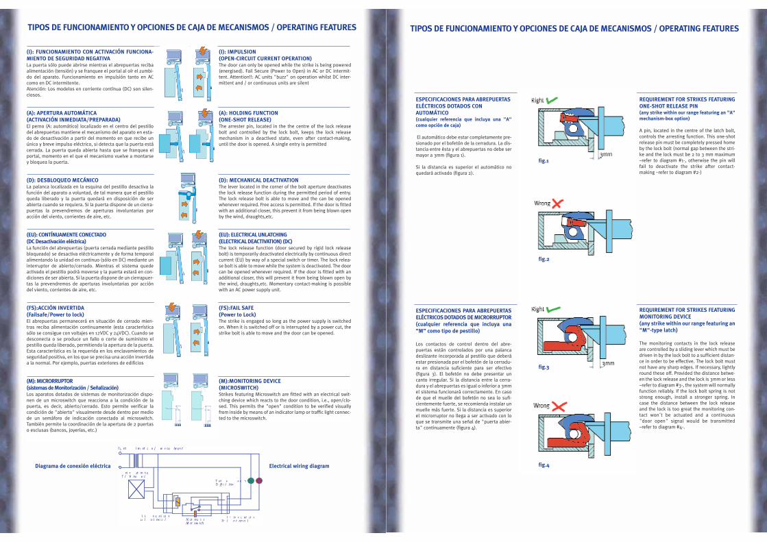
ESPECIFICACIONES PARA ABREPUERTASELÉCTRICOS DOTADOS CONAUTOMÁTICO(cualquier referencia que incluya una "A"como opción de caja)
El automático debe estar completamente pre-sionado por el bofetón de la cerradura. La dis-tancia entre ésta y el abrepuertas no debe sermayor a 3mm (figura 1).
Si la distancia es superior el automático noquedará activado (figura 2).
ESPECIFICACIONES PARA ABREPUERTASELÉCTRICOS DOTADOS DE MICRORRUPTOR (cualquier referencia que incluya una“M” como tipo de pestillo)
Los contactos de control dentro del abre-puertas están controlados por una palancadeslizante incorporada al pestillo que deberáestar presionada por el bofetón de la cerradu-ra en distancia suficiente para ser efectivo(figura 3). El bofetón no debe presentar uncanto irregular. Si la distancia entre la cerra-dura y el abrepuertas es igual o inferior a 3mmel sistema funcionará correctamente. En casode que el muelle del bofetón no sea lo sufi-cientemente fuerte, se recomienda instalar unmuelle más fuerte. Si la distancia es superiorel microrruptor no llega a ser activado con loque se transmite una señal de "puerta abier-ta" continuamente (figura 4).
REQUIREMENT FOR STRIKES FEATURINGONE-SHOT RELEASE PIN(any strike within our range featuring an "A"mechanism-box option)
A pin, located in the centre of the latch bolt,controls the arresting function. This one-shotrelease pin must be completely pressed homeby the lock bolt (normal gap between the stri-ke and the lock must be 2 to 3 mm maximum–refer to diagram #1-, otherwise the pin willfail to deactivate the strike after contact-making –refer to diagram #2-)
REQUIREMENT FOR STRIKES FEATURINGMONITORING DEVICE(any strike within our range featuring an"M"-type latch)
The monitoring contacts in the lock releaseare controlled by a sliding lever which must bedriven in by the lock bolt to a sufficient distan-ce in order to be effective. The lock bolt mustnot have any sharp edges. If necessary, lightlyround these off. Provided the distance betwe-en the lock release and the lock is 3mm or less–refer to diagram #3-, the system will normallyfunction reliably. If the lock bolt spring is notstrong enough, install a stronger spring. Incase the distance between the lock releaseand the lock is too great the monitoring con-tact won´t be actuated and a continuous"door open" signal would be transmitted–refer to diagram #4-.
TIPOS DE FUNCIONAMIENTO Y OPCIONES DE CAJA DE MECANISMOS / OPERATING FEATURES
fig.1
fig.2
fig.3
fig.4
(I): FUNCIONAMIENTO CON ACTIVACIÓN FUNCIONA-MIENTO DE SEGURIDAD NEGATIVA La puerta sólo puede abrirse mientras el abrepuertas recibaalimentación (tensión) y se franquee el portal al oír el zumbi-do del aparato. Funcionamiento en impulsión tanto en ACcomo en DC intermitente. Atención: Los modelos en corriente contínua (DC) son silen-ciosos.
(A): APERTURA AUTOMÁTICA (ACTIVACIÓN INMEDIATA/PREPARADA)El perno (A: automático) localizado en el centro del pestillodel abrepuertas mantiene el mecanismo del aparato en esta-do de desactivación a partir del momento en que recibe unúnico y breve impulso eléctrico, si detecta que la puerta estácerrada. La puerta queda abierta hasta que se franquea elportal, momento en el que el mecanismo vuelve a montarsey bloquea la puerta.
(D): DESBLOQUEO MECÁNICOLa palanca localizada en la esquina del pestillo desactiva lafunción del aparato a voluntad, de tal manera que el pestilloqueda liberado y la puerta quedará en disposición de serabierta cuando se requiera. Si la puerta dispone de un cierra-puertas la prevendremos de aperturas involuntarias poracción del viento, corrientes de aire, etc.
(EU): CONTÍNUAMENTE CONECTADO(DC Desactivación eléctrica) La función del abrepuertas (puerta cerrada mediante pestillobloqueado) se desactiva eléctricamente y de forma temporalalimentando la unidad en continuo (sólo en DC) mediante uninterruptor de abierto/cerrado. Mientras el sistema quedeactivado el pestillo podrá moverse y la puerta estará en con-diciones de ser abierta. Si la puerta dispone de un cierrapuer-tas la prevendremos de aperturas involuntarias por accióndel viento, corrientes de aire, etc.
(FS):ACCIÓN INVERTIDA(Failsafe/Power to lock)El abrepuertas permanecerá en situación de cerrado mien-tras reciba alimentación continuamente (esta característicasólo se consigue con voltajes en 12VDC y 24VDC). Cuando sedesconecta o se produce un fallo o corte de suministro elpestillo queda liberado, permitiendo la apertura de la puerta.Esta característica es la requerida en los enclavamientos deseguridad positiva, en los que se precisa una acción invertidaa la normal. Por ejemplo, puertas exteriores de edificios
(M): MICRORRUPTOR(sistemas de Monitorización / Señalización)Los aparatos dotados de sistemas de monitorización dispo-nen de un microswitch que reacciona a la condición de lapuerta, es decir, abierto/cerrado. Esto permite verificar lacondición de "abierto" visualmente desde dentro por mediode un semáforo de indicación conectado al microswitch.También permite la coordinación de la apertura de 2 puertaso esclusas (bancos, joyerías, etc.)
(I): IMPULSION (OPEN-CIRCUIT CURRENT OPERATION)The door can only be opened while the strike is being powered(energised). Fail Secure (Power to Open) in AC or DC intermit-tent. Attention!!: AC units "buzz" on operation whilst DC inter-mittent and / or continuous units are silent
(A): HOLDING FUNCTION(ONE-SHOT RELEASE)The arrester pin, located in the the centre of the lock releasebolt and controlled by the lock bolt, keeps the lock releasemechanism in a deactived state, even after contact-making,until the door is opened. A single entry is permitted
(D): MECHANICAL DEACTIVATION The lever located in the corner of the bolt aperture deactivatesthe lock release function during the permitted period of entry.The lock release bolt is able to move and the can be openedwhenever required. Free access is permitted. If the door is fittedwith an additional closer, this prevent it from being blown openby the wind, draughts,etc.
(EU): ELECTRICAL UNLATCHING(ELECTRICAL DEACTIVATION) (DC)The lock release function (door secured by rigid lock releasebolt) is temporarily deactivated electrically by continuous directcurrent (EU) by way of a special switch or timer. The lock relea-se bolt is able to move while the system is deactivated. The doorcan be opened whenever required. If the door is fitted with anadditional closer, this will prevent it from being blown open bythe wind, draughts,etc. Momentary contact-making is possiblewith an AC power supply unit.
(FS):FAIL SAFE(Power to Lock)The strike is engaged so long as the power supply is switchedon. When it is switched off or is interrupted by a power cut, thestrike bolt is able to move and the door can be opened.
(M):MONITORING DEVICE(MICROSWITCH)Strikes featuring Microswitch are fitted with an electrical swit-ching device which reacts to the door condition, i.e., open/clo-sed. This permits the "open" condition to be verified visuallyfrom inside by means of an indicator lamp or traffic light connec-ted to the microswitch.
TIPOS DE FUNCIONAMIENTO Y OPCIONES DE CAJA DE MECANISMOS / OPERATING FEATURES
Diagrama de conexión eléctrica Electrical wiring diagram

Los abrepuertas eléctricos proporcionan la seguri-dad de una puerta permanentemente cerrada altiempo que ofrecen la conveniencia de abrir ymonitorizar topo tipo de puertas (madera, metáli-cas, cristal,etc.). ASSEL dispone de abrepuertasidóneos para utilizar con una gran variedad decerraduras, perfiles y puertas.
PERFILES METÁLICOS
Los perfiles metálicos se utilizan generalmente enconstrucción de nueva planta y en reacondiciona-mientos. Para este tipo de perfiles se suelen insta-lar armaduras planas con avellanados paralelos enambos extremos de la misma. La armadura suelecubrir la distancia de 3-4 mm que queda entre lahoja de la puerta y el perfil.
PERFILES DE MADERA
Para perfiles de hasta 35 mm la solución construc-tiva más idónea es la utilización de armaduras enángulo -AN(U), ALL(U) y ALR(U) -. Éstas refuerzanla seguridad y estabilidad de la puerta y ofrecenventjas desde el punto de vista óptico. Cantos cua-drados o romos (éstos últimos permiten un ajustemás rápido al perfil), 3 mm de espesor y 4 (Serie01, 06, 07) ó 5 (Serie 10) agujeros de montaje ase-guran una sólida estabilidad.
Se recomienda la utilización de armaduras conlabios laterales de protección (P y P2) para aque-llos perfiles de anchura superior a los 35 mm enlos que existe una distancia considerable entre elborde del perfil y la caja de mecanismos (más de13 mm). El punto de alojamiento se traslada al cen-tro del perfil debido a la posición centrada de lacerradura. El borde del labio se puede rebajardurante la instalación parra adecuarlo al perfil.Mediante la utilización de estas armaduras seevita un excesivo rebaje en el perfil para la inclu-sión de “labios extensores” que lo debilitarían enexceso.
Electric strikes guarantee the security of a perma-nently locked door and still offer the convenienceof opening and monitoring any type of door (wood,metal or glass). ASSEL strikes are available for awide variety of locks, frame and door types withdifferent faceplates
STEEL PROFILES
Steel trims are particularly used for new buildingsand modernizations. If the door opener is later ins-talled in the steel frame, the faceplates should bescrewed on. A minimum 3-4 mm distance betweendoor leaf and the profile must be observed. Theedges of the later created opening are covered bythe faceplate.
WOO DEN PROFILES
With flush doors the latch remains only 3-4 mmbehind the impact edge. Thus conditionally anglefaceplates are necessary for taking the door ope-ner off. The stability of the construction is substan-tially improved by the use of angle faceplates-AN(U), ALL(U) and ALR(U) in our range-. With face-plates with radius no additional work is neededafter milling out. 3 mm of material thickness aswell as 4 (Serie 01,06,07) or 5 (Serie 10) mountingholes ensures solid stability.
With blunt closing doors the interference edge istransfered to the trim centrer by the usually centricpositioning of the lock in the door leaf. In order torealize optically closed constructions a distance of25 mm between impact and interference edgeneeds to be bridged. To that effect we do recom-mend the installation of lip-shaped faceplates (Pand P2 in our range). Thus, neither an excesivecut-out nor any kind of extension-lips (usuallyused with the ANSI style strikes) is required. Ifneeded the edge of the lip can be shortened onsite.
A P L I C A C I O N E S A P P L I C A T I O N S
(Series 01, 02/03, 06, 07, 08, 09, 10, 20)
(Series 01, 02-03, 04, 05, 06, 07, 08, 09, 10, 11, 20, 60, 80)
TIPO DE FUNCIONAMIENTO TIPO DE CAJA VOLTAJE CONSUMO AC CONSUMO DC RESISTENCIA Ω
DUTY MECHANISM BOX VOLTAGE AC CONSUMPTION DC CONSUMPTION RESISTANCE Ω
(I) 01,02,03,04,05, 8-12V AC 0,7 A 9Ω
IMPULSIÓN 06,07,08,09,11, 12V AC/DC 0,3 A 0,4 A 30Ω
12,60,80,90 24V AC/DC 220mA 340mA 70Ω
FAIL SECURE 110V AC*
AC OR DC INTERMITTENT 8-12V AC 0,9 A 7,5 Ω
10 12V AC/DC 0,41A 0,56 A 20 Ω
24V AC/DC 0,4 A 0,55 A 43 Ω
(EU) 01,02,03,04,05,
CONTINUAMENTE 06,07,08,09,11, 12V DC 160mA 70 Ω
CONECTADO 12,60,80.
24V DC 140mA 170 Ω
FAIL SECURE 10 12V DC 0,23 A 52 Ω
DC CONTINOUS
24V DC 0,15 A 180 Ω
(FS) 01,02,03,04,05,
ACCIÓN 06,07,08,09,12, 12V DC 160mA 70 Ω
INVERTIDA 60,80
24V DC 140mA 170 Ω
FAIL SAFE 10 12V DC 0,23 A 52 Ω
DC CONTINOUS
24V DC 0,15 A 180 Ω
* SÓLO PARA PAÍSES DONDE ESTÁ PERMITIDA ESTA TENSIÓN. POR RAZONES DE SEGURIDAD LOS ABREPUERTAS PREPARADOS PARA TRABAJAR EN ESTA TENSIÓN INCORPORAN
UN TORNILLO ESPECIAL PARA SU CONEXIÓN A UNA TOMA DE TIERRA
* TO BE USED ONLY IN THOSE COUNTRIES WHERE THIS VOLTAGE IS LEGALLY ALLOWED. FOR SAFETY REASONS STRIKES WORKING AT 110 V AC FEATURE A SPECIAL BUILT-IN
SCREW FOR EARTH CONNECTION
D AT O S E L É C T R I C O S / E L E C T R I C A L F E AT U R E S
pag. 2 / 4
CG/ 01/ VER 1.0/ 06.2002
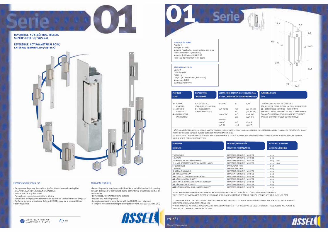
PESTILLOS DISPOSITIVOS VOLTAJE / RESISTENCIA (Ω)/ CONSUMO (Amp) FUNCIONAMIENTO
LATCH CASE OPTIONS VOLTAGE / RESISTANCE (Ω)/ CONSUMPTION (Amps) DUTY
NN = NORMAL AA = AUTOMÁTICO 8-12V AC 9Ω 0,7 A II = IMPULSIÓN - AC O DC INTERMITENTE
STANDARD (ONE-SHOT RELEASE PIN) (FAIL SECURE OR POWER TO OPEN - AC OR DC INTERMITTENT)EE = AJUSTABLE DD = DESBLOQUEO 24V AC/DC 70Ω 220 mA (AC) EEUU = DESBLOQUEO ELÉCTRICO - DC CONTINUO
ADJUSTABLE (UNLATCHING LEVER) 70Ω 340 mA (DC) (ELECTRICAL UNLATCHING : FAIL SECURE- DC CONTINUOUS)MM = MICRORUPTOR 12V AC/DC 30Ω 0,3 A (AC) FFSS = ACCIÓN INVERTIDA - DC CONTINUAMENTE CONECTADO
MICROSWITCH 30Ω 0,4 A (DC) (FAILSAFE OR POWER TO LOCK- DC CONTINUOUS)
110V AC* - -
12V DC 70Ω 160 mA
24V DC 170Ω 140 mA
* SÓLO PARA PAÍSES DONDE ESTÁ PERMITIDA ESTA TENSIÓN. POR RAZONES DE SEGURIDAD LOS ABREPUERTAS PREPARADOS PARA TRABAJAR EN ESTA TENSIÓN INCOR-
PORAN UN TORNILLO ESPECIAL PARA SU CONEXIÓN A UNA TOMA DE TIERRA.
*TO BE USED ONLY WITHIN THOSE COUNTRIES WHERE THIS VOLTAGE IS LEGALLY ALLOWED. FOR SAFETY REASONS STRIKES WORKING AT 110VAC FEATURE A SPECIAL
BUILT-IN SCREW FOR EARTH CONNECTION.
ARMADURA MONTAJE /INSTALACIÓN MATERIAL Y ACABADOS
FACEPLATE MOUNTING / INSTALLATION MATERIAL & FINISHES
TT (STANDARD) EMPOTRAR (EMBUTIR) / MORTISE 1 - 19LL (LARGA) EMPOTRAR (EMBUTIR) / MORTISE 1 - 19PP (LABIO DE PROTECCIÓN LATERAL)* EMPOTRAR (EMBUTIR) / MORTISE 1 - 13 / 18-19PP22 (LABIO DE PROTECCIÓN LATERAL, CALADO LARGO)* EMPOTRAR (EMBUTIR) / MORTISE 1 - 13 / 18-19SS (SUPERFICIE) SOBREPONER / RIM 1 - 13FF (FUNDA) SOBREPONER / RIM 1 - 13HH (LARGA SIN CALADO) EMPOTRAR (EMBUTIR) / MORTISE 1 - 19AANN (ÁNGULO CORTA)** EMPOTRAR (EMBUTIR) / MORTISE 1 - 19AANNUU (ÁNGULO CORTA CANTOS ROMOS)** EMPOTRAR (EMBUTIR) / MORTISE 1 - 19AALLRR (ÁNGULO LARGA DIN-R)** EMPOTRAR (EMBUTIR) / MORTISE 1 - 19AALLRRUU (ÁNGULO LARGA DIN-R CANTOS ROMOS)** EMPOTRAR (EMBUTIR) / MORTISE 1 - 19AALLLL (ÁNGULO LARGA DIN-L)** EMPOTRAR (EMBUTIR) / MORTISE 1 - 19AALLLLUU (ÁNGULO LARGA DIN-L CANTOS ROMOS)** EMPOTRAR (EMBUTIR) / MORTISE 1 - 19
*ESTAS ARMADURAS GUARDAN MANO: ESPECIFICAR DIN-L Ó DIN-R EN EL PEDIDO DESPUÉS DEL CÓDIGO DE ARMADURA DESEADO
*THESE FACEPLATESARE HANDED. PLEASE SPECIFY HAND DESIRED WHEN ORDERING BY ADDING “DIN-L” OR “DIN-R” AFTER THE FACEPLATE CODE
** CUANDO SE MONTA CON CUALQUIERA DE NUESTRAS ARMADURAS EN ÁNGULO LA CAJA DE MECANISMOS NO LLEVA TAPA POR LO QUE ESTOS MODELOS
SIEMPRE SE SERVIRÁN MONTADOS DE FÁBRICA
** WHEN MOUNTED WITH ANGLED FACEPLATES THE MECHANISM BOX DOESN´T FEATURE ANY METAL COVER. THEREFORE THESE MODELS WILL ALWAYS BE
SUPPLIED FULLY ASSEMBLED FROM THE FACTORY
54
23,5
47
33,5
105
2820,5
9,5
46,5
33,5
52
5,5
MONTAJE DE SERIEPestillo NVoltaje= 8-12VACMaterial / acabado= hierro pintado gris plataFuncionamiento= I (impulsión)Montaje de fábrica= DIN RIGHTTapa-caja de mecanismos de acero
01
STANDARD VERSIONLatch=NCoil= 8-12VACFinish= 1Duty= I (AC Intermittent, fail secure)Mounting= DIN RStainless-steel cover
REVERSIBLE, NO SIMÉTRICO, REGLETASUPERPUESTA (105*28*20,5)
REVERSIBLE, NOT SYMMETRICAL BODY,EXTERNAL TERMINAL (105*28*20,5)
ESPECIFICACIONES TÉCNICAS
- Para puertas de paso y de condena (en función de la armadura elegida)- DISEÑO DE CAJA REVERSIBLE, NO SIMÉTRICA- Puertas metálicas y de madera- Para voltajes especiales, consultar a fábrica- Mecanismos protegidos contra la corrosión de acuerdo con la norma UNI- ISO 9227.- Conforme a norma armonizada 89/336/EEC (EN55014) de la compatibilidadelectromagnética.
TECHNICAL FEATURES
- Depending on the faceplate used this strike is suitable for deadbolt passingthrough doors and/or sashlocked doors, both internal or external, mortice orrim mounted - REVERSIBLE,NOT SYMMETRICAL DESIGN - Metallic and wooden profiles - Corrosion resistant in accordance with the UNI ISO 9227 standard- It complies with the electromagnetic compatibility norm. 89/336/EEC (EN55014)
460 (PETILLO N / N LATCH)410 (PESTILLO E / E LATCH)
200

pag. 4/ 4
CG/ 01/ VER 1.0/ 06.2002
7
30
90
47
80
3
5
5,5
14
74
40
250
44
65
25 19
(serie 01/06/07)75
(serie 10)
28
12
64
44
25040
74
2810
102532
9
15
105 (Serie 01)90 (Serie 06,07)
15
12
64
10
44
40
74
28
250
10 9
25 32
15
15
105 (Serie 01)90 (Serie 06,07)
12
15
102532
142
54
44
64
172
10
IncompatibilidadesLos modelos de corriente alterna (AC), así como los mixtos (AC/DC) funcionarán siempre en impulsión (I). También llamados de ciclo discontinuo de trabajo .Los pestillos dotados de Microrruptor (M) no se pueden combinar con las siguientes opciones de pestillo y mecanismos: Automático (A), Ajustable (E) y Desbloqueo mecánico (D).Los modelos de corriente continua pura (DC) pueden estar continuamente alimentados, también llamados de ciclo continuo de trabajo, tanto en funcionamiento normal (EU) como en accióninvertida (FS).Los modelos de corriente continua pura (DC) no pueden llevar dispositivo automático (A) y el bofetón de la cerradura no debe ejercer presión alguna sobre la parte móvil del abrepuertas, unaincorrecta instalación causaría un fallo de funcionamiento.
IncompatibilityMonitorised strikes are not available in conjuction with one-shot release pin (A), adjustable latch (E) and mechanical unlatching lever (D) - Unlatching is achieved electrically (EU).AC and AC/DC strikes are fail-secure (I) -operated by an AC or DC intermittently-energized solenoid-. DC continuously-rated strikes can be fail-secure (EU) or fail-safe (FS) and cannot featureone-shot release pin (A).When installing DC powered electric door strikes, it is necessary to allow for clearance between the bolt and the latch when they are in a locked position (referred to as door loading). If thebolt presses against the latch, it may cause the unit to be inoperable.
01
pag. 3/ 4
CG/ 01/ VER 1.0/ 06.2002
21
104
160
50
66
253
21
104
160
50
66
253
28
44
107
19
25
44
38
19
37
145
22
25
44
39
108
33 50
28
104
250
64
44
40
74
12
21
0 1 N _ TT 1 1 1 I
0 1 N _ L 1 1 1 I
01
28
104
250
64
44
40
74
21
ED
CBA
IH
GF
AB
C
DE
0 1 N _ h 1 1 1 I
0 1 N _ f 1 1 1 I 0 1 N _ s 1 1 1 I
0 1 N _ p ( D I N L ) 1 1 1 I
0 1 N _ a l l 1 1 1 I
0 1 N _ a l r 1 1 1 I
0 1 E _ a n 1 1 1 I
F
H
G
I
pag. 2 / 2
CG/ 0203/ VER 1.0/ 06.2002
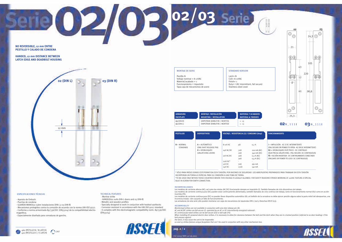
PESTILLOS DISPOSITIVOS VOLTAJE / RESISTENCIA (Ω)/ CONSUMO (Amp) FUNCIONAMIENTO
NN = NORMAL AA = AUTOMÁTICO 8-12V AC 9Ω 0,7 A II = IMPULSIÓN - AC O DC INTERMITENTE
STANDARD (ONE-SHOT RELEASE PIN) (FAIL SECURE OR POWER TO OPEN - AC OR DC INTERMITTENT)DD = DESBLOQUEO 24V AC/DC 70Ω 220 mA (AC) EEUU = DESBLOQUEO ELÉCTRICO - DC CONTINUO
(UNLATCHING LEVER) 70Ω 340 mA (DC) (ELECTRICAL UNLATCHING : FAIL SECURE- DC CONTINUOUS)
12V AC/DC 30Ω 0,3 A (AC) FFSS = ACCIÓN INVERTIDA - DC CONTINUAMENTE CONECTADO
30Ω 0,4 A (DC) (FAILSAFE OR POWER TO LOCK- DC CONTINUOUS)
110V AC* - -
12V DC 70Ω 160 mA
24V DC 170Ω 140 mA
* SÓLO PARA PAÍSES DONDE ESTÁ PERMITIDA ESTA TENSIÓN. POR RAZONES DE SEGURIDAD LOS ABREPUERTAS PREPARADOS PARA TRABAJAR EN ESTA TENSIÓN
INCORPORAN UN TORNILLO ESPECIAL PARA SU CONEXIÓN A UNA TOMA DE TIERRA.
*TO BE USED ONLY WITHIN THOSE COUNTRIES WHERE THIS VOLTAGE IS LEGALLY ALLOWED. FOR SAFETY REASONS STRIKES WORKING AT 110VAC FEATURE A SPECIAL
BUILT-IN SCREW FOR EARTH CONNECTION.
ARMADURA MONTAJE /INSTALACIÓN MATERIAL Y ACABADOS
FACEPLATE MOUNTING / INSTALLATION MATERIAL & FINISHES
0033 (DIN-R) EMPOTRAR (EMBUTIR) / MORTISE 1 - 130022 (DIN-L) EMPOTRAR (EMBUTIR) / MORTISE 1 - 13
25,3
220
105
90,8
24,3
43
61
17
21
0302
12
INCOMPATIBILIDADESLos modelos de corriente alterna (AC), así como los mixtos (AC/DC) funcionarán siempre en impulsión (I). También llamados de ciclo discontinuo de trabajo.Los modelos de corriente continua pura (DC) pueden estar continuamente alimentados, también llamados de ciclo continuo de trabajo, tanto en funcionamiento normal (EU) como en accióninvertida (FS).Los modelos de corriente continua pura (DC) no pueden llevar dispositivo automático (A) y el bofetón de la cerradura no debe ejercer presión alguna sobre la parte móvil del abrepuertas, unaincorrecta instala- ción causaría un fallo de funcionamiento.Las armaduras de esta serie sólo pueden montarse con cajas de mecanismos de Izquierdas DIN L (02) y Derechas DIN R (03).
INCOMPATIBILITYMonitorised strikes are not available in conjuction with one-shot release pin (A).AC and AC/DC strikes are fail-secure (I) -operated by an AC or DC intermittently-energized solenoid-.DC continuously-rated strikes can be fail-secure (EU) or fail-safe (FS).When installing DC powered electric door strikes, it is necessary to allow for clearance between the bolt and the latch when they are in a locked position (referred to as door loading). If thebolt presses againstthe latch, it may cause the unit to be inoperable.02 and 03 strikes feature unique faceplates that can´t be used in conjuction with any other mechanism box.
02/03
NO REVERSIBLE, 12 mm ENTREPESTILLO Y CALADO DE CONDENA
HANDED, 12 mm DISTANCE BETWEENLATCH EDGE AND DEADBOLT HOUSING
ESPECIFICACIONES TÉCNICAS
- Aparato de Embutir.- Puertas de condena- GUARDA MANO(02 cubre instalaciones DIN-L y 03 DIN-R)- Mecanismos protegidos contra la corrosión de acuerdo con la norma UNI-ISO 9227.- Conforme a norma armonizada 89/336/EEC (EN55014) de la compatibilidad electro-magnética.- Especialmente diseñado para cerraduras de gancho.
TECHNICAL FEATURES- Mortise strike- HANDED(02 suits DIN-L doors and 03 DIN-R)
- Metallic and wooden profiles- Specially designed to work in conjuction with hooked sashlocks- Corrosion resistant in accordance with the UNI ISO 9227 standard- It complies with the electromagnetic compatibility norm. 89/336/EEC(EN55014)
03 (DIN R) 02 (DIN L)
12 mm
MONTAJE DE SERIE
Pestillo NVoltaje nominal = 8-12VACMaterial/acabado = 1Funcionamiento = impulsiónTapa-caja de mecanismos de acero
STANDARD VERSION
Latch=NCoil= 8-12VACFinish= 1Duty= I (AC Intermittent, fail secure)Stainless-steel cover
03 N _ 1 1 1 I02N _ 1 1 1 I
460 (PETILLO N / N LATCH)410 (PESTILLO E / E LATCH)
307
pag. 2 / 2
CG/ 04/ VER 1.0/ 06.2002
PESTILLOS** DISPOSITIVOS VOLTAJE / RESISTENCIA (Ω)/ CONSUMO (Amp) FUNCIONAMIENTO
LATCH** CASE OPTIONS VOLTAGE / RESISTANCE (Ω)/ CONSUMPTION (Amps) DUTY
NN = NORMAL DD = DESBLOQUEO 8-12V AC 9Ω 0,7 A II = IMPULSIÓN - AC O DC INTERMITENTE
STANDARD (UNLATCHING LEVER) (FAIL SECURE OR POWER TO OPEN - AC OR DC INTERMITTENT)MM = MICRORUPTOR 24V AC/DC 70Ω 220 mA (AC) EEUU = DESBLOQUEO ELÉCTRICO - DC CONTINUO
MICROSWITCH 70Ω 340 mA (DC) (ELECTRICAL UNLATCHING : FAIL SECURE- DC CONTINUOUS)
12V AC/DC 30Ω 0,3 A (AC) FFSS = ACCIÓN INVERTIDA - DC CONTINUAMENTE CONECTADO
30Ω 0,4 A (DC) (FAILSAFE OR POWER TO LOCK- DC CONTINUOUS)
110V AC* - -
12V DC 70Ω 160 mA
24V DC 170Ω 140 mA
* SÓLO PARA PAÍSES DONDE ESTÁ PERMITIDA ESTA TENSIÓN. POR RAZONES DE SEGURIDAD LOS ABREPUERTAS PREPARADOS PARA TRABAJAR EN ESTA TENSIÓN INCORPO-
RAN UN TORNILLO ESPECIAL PARA SU CONEXIÓN A UNA TOMA DE TIERRA.
*TO BE USED ONLY WITHIN THOSE COUNTRIES WHERE THIS VOLTAGE IS LEGALLY ALLOWED. FOR SAFETY REASONS STRIKES WORKING AT 110VAC FEATURE A SPECIAL BUILT-
IN SCREW FOR EARTH CONNECTION.
**PROFUNDO PESTILLO DE 12 mm
**12mm DEEP JAW
ARMADURA MONTAJE /INSTALACIÓN MATERIAL Y ACABADOS
FACEPLATE MOUNTING / INSTALLATION MATERIAL & FINISHES
LA PROPIA DE SU VERSIÓN / EMPOTRAR (EMBUTIR) / MORTISE 1 - 13
PLEASE NOTE THAT THIS STRIKE FEATURES A
SPECIAL FACEPLATE OF ITS OWN AND CAN NOT BE
SUPPLIED WITH NO OTHER TYPE OF FOREND
282320,5
105135
76
47
30
153
22,53
7
INCOMPATIBILIDADESLos modelos de corriente alterna (AC), así como los mixtos (AC/DC) funcionarán siempre en impulsión (I). También llamados de ciclo discontinuo de trabajo .Los pestillos dotados de Microrruptor (M) no se pueden combinar con las siguientes opciones de mecanismos: Desbloqueo mecánico (D).Los modelos de corriente continua pura (DC) pueden estar continuamente alimentados, también llamados de ciclo continuo de trabajo, tanto en funcionamiento normal (EU) como enacción invertida (FS).Los modelos de corriente continua pura (DC) no pueden llevar dispositivo automático (A) y el bofetón de la cerradura no debe ejercer presión alguna sobre la parte móvil del abrepuertas,una incorrecta instalación causaría un fallo de funcionamiento.
INCOMPATIBILITYMonitorised strikes are not available in conjuction with a mechanical unlatching lever (D). Unlatching is achieved electrically (EU).AC and AC/DC strikes are fail-secure (I) -operated by an AC or DC intermittently-energized solenoid-.DC continuously-rated strikes can be fail-secure (EU) or fail-safe (FS).When installing DC powered electric door strikes, it is necessary to allow for clearance between the bolt and the latch when they are in a locked position (referred to as door loading). If thebolt presses against the latch, it may cause the unit to be inoperable.
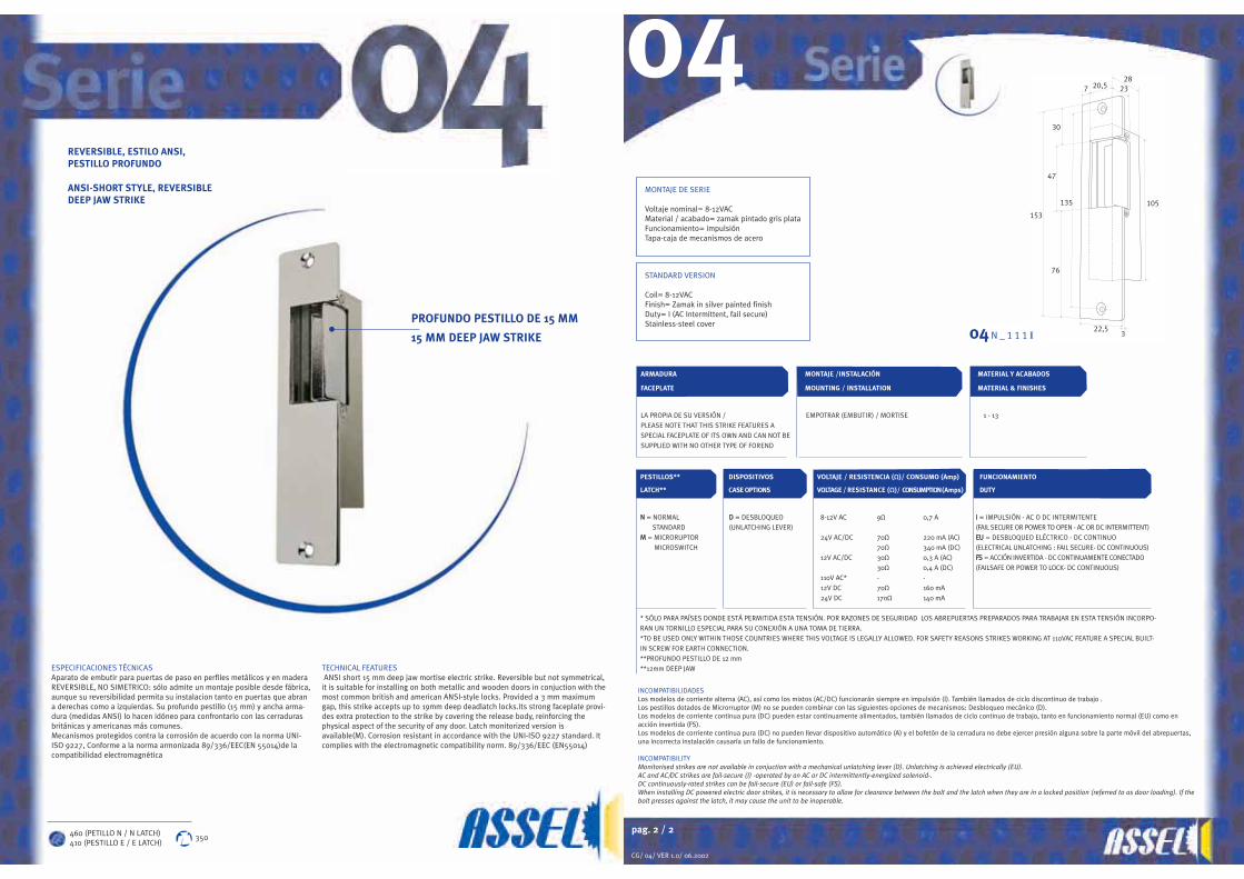
04REVERSIBLE, ESTILO ANSI,PESTILLO PROFUNDO
ANSI-SHORT STYLE, REVERSIBLEDEEP JAW STRIKE
PROFUNDO PESTILLO DE 15 MM
15 MM DEEP JAW STRIKE
ESPECIFICACIONES TÉCNICASAparato de embutir para puertas de paso en perfiles metálicos y en maderaREVERSIBLE, NO SIMETRICO: sólo admite un montaje posible desde fábrica,aunque su reversibilidad permita su instalacion tanto en puertas que abrana derechas como a izquierdas. Su profundo pestillo (15 mm) y ancha arma-dura (medidas ANSI) lo hacen idóneo para confrontarlo con las cerradurasbritánicas y americanas más comunes.Mecanismos protegidos contra la corrosión de acuerdo con la norma UNI-ISO 9227, Conforme a la norma armonizada 89/336/EEC(EN 55014)de lacompatibilidad electromagnética
TECHNICAL FEATURESANSI short 15 mm deep jaw mortise electric strike. Reversible but not symmetrical,
it is suitable for installing on both metallic and wooden doors in conjuction with themost common british and american ANSI-style locks. Provided a 3 mm maximumgap, this strike accepts up to 19mm deep deadlatch locks.Its strong faceplate provi-des extra protection to the strike by covering the release body, reinforcing thephysical aspect of the security of any door. Latch monitorized version isavailable(M). Corrosion resistant in accordance with the UNI-ISO 9227 standard. Itcomplies with the electromagnetic compatibility norm. 89/336/EEC (EN55014)
STANDARD VERSION
Coil= 8-12VACFinish= Zamak in silver painted finishDuty= I (AC Intermittent, fail secure)Stainless-steel cover
MONTAJE DE SERIE
Voltaje nominal= 8-12VACMaterial / acabado= zamak pintado gris plataFuncionamiento= impulsiónTapa-caja de mecanismos de acero
04 N _ 1 1 1 I
460 (PETILLO N / N LATCH)410 (PESTILLO E / E LATCH)
350

pag. 2 / 2
CG/ 05/ VER 1.0/ 06.2002
PESTILLOS** DISPOSITIVOS VOLTAJE / RESISTENCIA (Ω)/ CONSUMO (Amp) FUNCIONAMIENTO
LATCH** CASE OPTIONS VOLTAGE / RESISTANCE (Ω)/ CONSUMPTION (Amps) DUTY
NN = NORMAL 8-12V AC 9Ω 0,7 A II = IMPULSIÓN - AC O DC INTERMITENTE
STANDARD (FAIL SECURE OR POWER TO OPEN - AC OR DC INTERMITTENT)
24V AC/DC 70Ω 220 mA (AC) EEUU = DESBLOQUEO ELÉCTRICO - DC CONTINUO
70Ω 340 mA (DC) (ELECTRICAL UNLATCHING : FAIL SECURE- DC CONTINUOUS)
12V AC/DC 30Ω 0,3 A (AC) FFSS = ACCIÓN INVERTIDA - DC CONTINUAMENTE CONECTADO
30Ω 0,4 A (DC) (FAILSAFE OR POWER TO LOCK- DC CONTINUOUS)
110V AC* - -
12V DC 70Ω 160 mA
24V DC 170Ω 140 mA
* SÓLO PARA PAÍSES DONDE ESTÁ PERMITIDA ESTA TENSIÓN. POR RAZONES DE SEGURIDAD LOS ABREPUERTAS PREPARADOS PARA TRABAJAR EN ESTA TENSIÓN INCORPO-
RAN UN TORNILLO ESPECIAL PARA SU CONEXIÓN A UNA TOMA DE TIERRA
*TO BE USED ONLY WITHIN THOSE COUNTRIES WHERE THIS VOLTAGE IS LEGALLY ALLOWED. FOR SAFETY REASONS STRIKES WORKING AT 110VAC FEATURE A SPECIAL BUILT-
IN SCREW FOR EARTH CONNECTION
** PESTILLO ESPECIAL PARA RECIBIR PALANCAS DE CERRADURAS TIPO INGERSOLLTM SC-71
** SPECIAL LATCH SUITABLE FOR INGERSOLLTM SC-71 RIM DEADLOCKING TYPE LOCKS
ARMADURA
MONTAJE /INSTALACIÓN MATERIAL Y ACABADOS
FACEPLATE MOUNTING / INSTALLATION MATERIAL & FINISHESLA PROPIA DE SU VERSIÓN / SOBREPONER / RIM 1 - 13
PLEASE NOTE THAT THIS STRIKE FEATURES A
SPECIAL FACEPLATE OF ITS OWN AND CAN NOT BE
SUPPLIED WITH NO OTHER TYPE OF FOREND
108
4563,5
35
8 3,512,7
41
41
12,7
25,7
5230,5
51,7
15,9
57,2 88,9
66,7
INCOMPATIBILIDADESLos modelos de corriente alterna (AC), así como los mixtos (AC/DC) funcionarán siempre en impulsión (I). También llamados de ciclo discontinuo de trabajo .Los modelos de corriente continua pura (DC) pueden estar continuamente alimentados, también llamados de ciclo continuo de trabajo, tanto en funcionamiento normal (EU) como enacción invertida (FS).El bofetón de la cerradura no debe ejercer presión alguna sobre la parte móvil del abrepuertas, una incorrecta instalación causaría un fallo de funcionamiento.
INCOMPATIBILITYAC and AC/DC strikes are fail-secure (I) -operated by an AC or DC intermittently-energized solenoid-.DC continuously-rated strikes can be fail-secure (EU) or fail-safe (FS).When installing DC powered electric door strikes, it is necessary to allow for clearance between the bolt and the latch when they are in a locked position (referred to as door loading).If the bolt presses against the latch, it may cause the unit to be inoperable.
0 5 1 1 1 I
IngersollTM SC71
05ABREPUERTAS DE SUPERFICIE PARACERRADURAS DE CONDENA AUTOMÁTICA
RIM STRIKE FOR AUTOMATIC DEADLOCKS
IngersollTM SC71
ESPECIFICACIONES TÉCNICASAparato de sobreponer específicamente diseñado para puertas de condenaautomática, interiores o exteriores, dotadas de cerraduras de sobreponer tiponight-latch del tipo IngersollTM SC-71. REVERSIBLE, NO SIMETRICO, este abre-puertas eléctrico admite su instalación tanto en perfiles metálicos como enmadera. Regleta de conexiones protegida por la carcasa del abrepuertas, impi-diendo contactos directos. Mecanismos protegidos contra la corrosión de acuer-do con la norma UNI ISO 9227. Conforme a la norma armonizada89/336/EEC(EN 55014)de la compatibilidad electromagnética.
TECHNICAL FEATURESReversible rim surface-mounted electric strike. Suitable to be used in conjuctionwith rim automatic deadlocks like the IngersollTM SC-71 lock (not suitable withthe IngersollTM SC-73 fire rim lock). Supplied with a built-in terminal that provi-des an extra-protection to the strike against unproper contacts. Corrosion resis-tant in accordance with the UNI ISO 9227 standard. It complies with the electro-magnetic compatibility norm. 89/336/EEC (EN55014).
460 515
M O N TAJ E D E S E R I E
Voltaje nominal= 8-12VACAcabado= hierro pintado gris plataFuncionamiento= I (impulsión)
STANDARD VERSION
Coil= 8-12VAC Finish= 1Duty= I (AC Intermittent, fail secure)
pag. 2 / 4
CG/ 06/ VER 1.0/ 06.2002
PESTILLOS DISPOSITIVOS VOLTAJE / RESISTENCIA (Ω)/ CONSUMO (Amp) FUNCIONAMIENTO
LATCH CASE OPTIONS VOLTAGE / RESISTANCE (Ω)/ CONSUMPTION (Amps) DUTY
NN = NORMAL AA = AUTOMÁTICO 8-12V AC 9Ω 0,7 A II = IMPULSIÓN - AC O DC INTERMITENTE
STANDARD (ONE-SHOT RELEASE PIN) (FAIL SECURE OR POWER TO OPEN - AC OR DC INTERMITTENT)EE = AJUSTABLE DD = DESBLOQUEO 24V AC/DC 70Ω 220 mA (AC) EEUU = DESBLOQUEO ELÉCTRICO - DC CONTINUO
ADJUSTABLE (UNLATCHING LEVER) 70Ω 340 mA (DC) (ELECTRICAL UNLATCHING : FAIL SECURE- DC CONTINUOUS)
12V AC/DC 30Ω 0,3 A (AC) FFSS = ACCIÓN INVERTIDA - DC CONTINUAMENTE CONECTADO
30Ω 0,4 A (DC) (FAILSAFE OR POWER TO LOCK- DC CONTINUOUS)
110V AC* - -
12V DC 70Ω 160 mA
24V DC 170Ω 140 mA
* SÓLO PARA PAÍSES DONDE ESTÁ PERMITIDA ESTA TENSIÓN. POR RAZONES DE SEGURIDAD LOS ABREPUERTAS PREPARADOS PARA TRABAJAR EN ESTA TENSIÓN INCORPORAN UNTORNILLO ESPECIAL PARA SU CONEXIÓN A UNA TOMA DE TIERRA.*TO BE USED ONLY WITHIN THOSE COUNTRIES WHERE THIS VOLTAGE IS LEGALLY ALLOWED. FOR SAFETY REASONS STRIKES WORKING AT 110VAC FEATURE A SPECIAL BUILT-INSCREW FOR EARTH CONNECTION.
ARMADURA MONTAJE /INSTALACIÓN MATERIAL Y ACABADOS
FACEPLATE MOUNTING / INSTALLATION MATERIAL & FINISHES
TT (STANDARD) EMPOTRAR (EMBUTIR) / MORTISE 1 - 19LL (LARGA) EMPOTRAR (EMBUTIR) / MORTISE 1 - 19PP (LABIO DE PROTECCIÓN LATERAL)* EMPOTRAR (EMBUTIR) / MORTISE 1 - 13 / 18-19PP22 (LABIO DE PROTECCIÓN LATERAL, CALADO LARGO)* EMPOTRAR (EMBUTIR) / MORTISE 1 - 13 / 18-19FF (FUNDA) SOBREPONER / RIM 1 - 13SS (SUPERFICIE) SOBREPONER / RIM 1 - 13FF (FUNDA) SOBREPONER / RIM 1 - 13HH (LARGA SIN CALADO) EMPOTRAR (EMBUTIR) / MORTISE 1 - 19AANN (ÁNGULO CORTA)*** EMPOTRAR (EMBUTIR) / MORTISE 1 - 19AANNUU (ÁNGULO CORTA CANTOS ROMOS)*** EMPOTRAR (EMBUTIR) / MORTISE 1 - 19AALLRR (ÁNGULO LARGA DIN-R)*** EMPOTRAR (EMBUTIR) / MORTISE 1 - 19AALLRRUU (ÁNGULO LARGA DIN-R CANTOS ROMOS)*** EMPOTRAR (EMBUTIR) / MORTISE 1 - 19AALLLL (ÁNGULO LARGA DIN-L)*** EMPOTRAR (EMBUTIR) / MORTISE 1 - 19AALLLLUU (ÁNGULO LARGA DIN-L CANTOS ROMOS)*** EMPOTRAR (EMBUTIR) / MORTISE 1 - 19RR (REVERSIBLE)** EMPOTRAR (EMBUTIR) / MORTISE 1 - 19RR22 (REVERSIBLE-2)** EMPOTRAR (EMBUTIR) / MORTISE 1 - 19RRGG (REVERSIBLE-GANCHO)** EMPOTRAR (EMBUTIR) / MORTISE 1 - 19
*ESTAS ARMADURAS GUARDAN MANO: ESPECIFICAR DIN-L Ó DIN-R EN EL PEDIDO DESPUÉS DEL CÓDIGO DE ARMADURA DESEADO*THESE FACEPLATES ARE HANDED. PLEASE SPECIFY HAND DESIRED WHEN ORDERING BY ADDING “DIN-L” OR “DIN-R” AFTER THE FACEPLATE CODE**SÓLO DISPONIBLES PARA MONTAJE DIN-L**ONLY AVAILABLE IN DIN-L MOUNTING*** CUANDO SE MONTA CON CUALQUIERA DE NUESTRAS ARMADURAS EN ÁNGULO LA CAJA DE MECANISMOS NO LLEVA TAPA POR LO QUE ESTOS MODELOS SIEMPRE SESERVIRÁN MONTADOS DE FÁBRICA*** WHEN MOUNTED WITH ANGLED FACEPLATES THE MECHANISM BOX DOESN´T FEATURE ANY METAL COVER. THEREFORE THESE MODELS WILL ALWAYS BE SUPPLIED FULLYASSEMBLED FROM THE FACTORY
33
90
9,5
47
33,5
52
12.5
5,5
2820,5
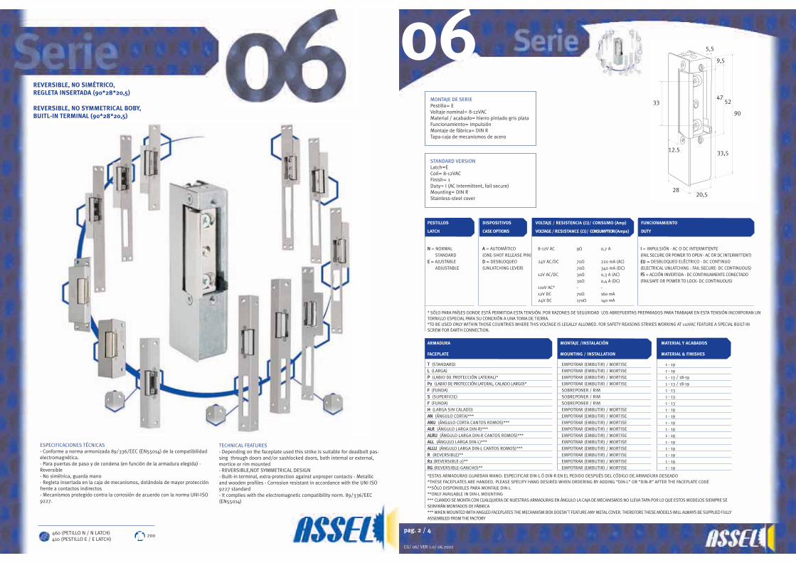
06REVERSIBLE, NO SIMÉTRICO,REGLETA INSERTADA (90*28*20,5)
REVERSIBLE, NO SYMMETRICAL BOBY,BUITL-IN TERMINAL (90*28*20,5)
ESPECIFICACIONES TÉCNICAS- Conforme a norma armonizada 89/336/EEC (EN55014) de la compatibilidadelectromagnética.- Para puertas de paso y de condena (en función de la armadura elegida) -Reversible- No simétrica, guarda mano - Regleta insertada en la caja de mecanismos, dotándola de mayor protecciónfrente a contactos indirectos - Mecanismos protegido contra la corrosión de acuerdo con la norma UNI-ISO9227.
TECHNICAL FEATURES- Depending on the faceplate used this strike is suitable for deadbolt pas-sing through doors and/or sashlocked doors, both internal or external,mortice or rim mounted- REVERSIBLE,NOT SYMMETRICAL DESIGN- Built-in terminal, extra-protection against unproper contacts - Metallicand wooden profiles - Corrosion resistant in accordance with the UNI ISO9227 standard- It complies with the electromagnetic compatibility norm. 89/336/EEC(EN55014)
460 (PETILLO N / N LATCH)410 (PESTILLO E / E LATCH)
200
MONTAJE DE SERIEPestillo= EVoltaje nominal= 8-12VACMaterial / acabado= hierro pintado gris plataFuncionamiento= impulsiónMontaje de fábrica= DIN RTapa-caja de mecanismos de acero
STANDARD VERSIONLatch=ECoil= 8-12VACFinish= 1Duty= I (AC Intermittent, fail secure)Mounting= DIN RStainless-steel cover

pag. 4 / 4
CG/ 06/ VER 1.0/ 06.2002
90
47
310
33
25
16250
74
64
44
14,5
28
12
2552
90
47
310
25
16250
91
64
44
17
28
52
90
47
310
33
25
16250
61
64
44
17
28
64
44
25040
74
2810
102532
9
15
105 (Serie 01)90 (Serie 06,07)
15
12
64
10
44
40
74
28
250
10 9
25 32
15
15
105 (Serie 01)90 (Serie 06,07)
12
INCOMPATIBILIDADESLos modelos de corriente alterna (AC), así como los mixtos (AC/DC) funcionarán siempre en impulsión (I). También llamados de ciclo discontinuo de trabajo .Los modelos de corriente continua pura (DC) pueden estar continuamente alimentados, también llamados de ciclo continuo de trabajo, tanto en funcionamiento normal (EU) como enacción invertida (FS).Los modelos de corriente continua pura (DC) no pueden llevar dispositivo automático (A) y el bofetón de la cerradura no debe ejercer presión alguna sobre la parte móvil del abrepuer-tas, una incorrecta instalación causaría un fallo de funcionamiento.
INCOMPATIBILITYAC and AC/DC strikes are fail-secure (I) -operated by an AC or DC intermittently-energized solenoid-.DC continuously-rated strikes can be fail-secure (EU) or fail-safe (FS) and cannot feature one-shot release pin (A).When installing DC powered electric door strikes, it is necessary to allow for clearance between the bolt and the latch when they are in a locked position (referred to as door loading).If the bolt presses against thelatch, it may cause the unit to be inoperable.
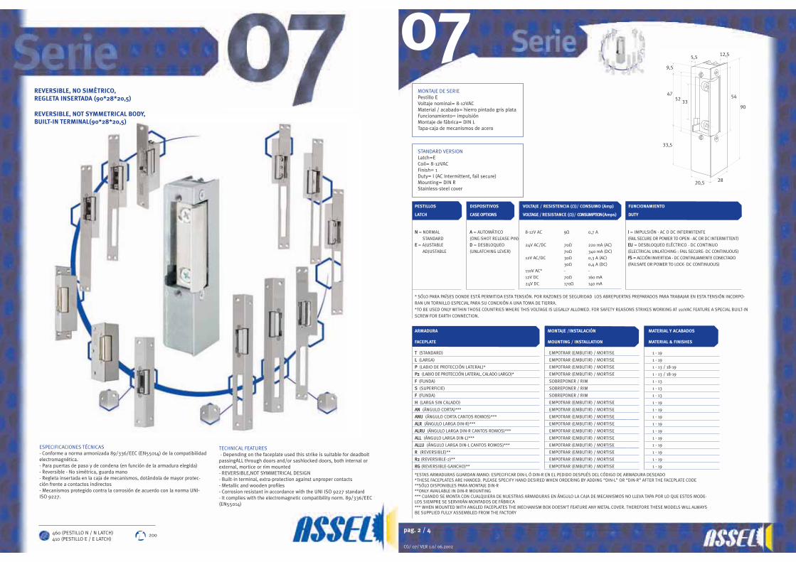
7
30
90
47
80
3
5
5,5
14
74
40
250
44
65
25 19
(serie 01/06/07)75
(serie 10)
28
12
06
pag. 3 / 4
CG/ 06/ VER 1 0/ 06 2002
10
52
25
90
47
66
160
44
50
3
28
5290
47
310
33
25
250
64
44
28
5290
47
310
33
40 250
74
64
44
12
28
107
19
25
44
38
19
37
145
15
102532
142
54
44
64
172
10
33
108 44
25
39
50
22FED
CBA
06
LKJ
IHG
0 6 N _ tt 1 1 1 I
0 6 N _ s 1 1 1 I0 6 N _ f 1 1 1 I
0 6 E A h 1 1 1 I
0 6 E _ a n 1 1 1 I
0 6 E A l 1 1 1 I
0 6 E A rg 1 1 1 I0 6 N _ R2 1 1 1 I0 6 N _ r 1 1 1 I
0 6 N _ p ( D I N L ) 1 1 1 I0 6 N _ a l r 1 1 1 I0 6 N _ a l l 1 1 1 I
AB
C
D
E
F
L
HG
I
J
K
pag. 2 / 4
CG/ 07/ VER 1.0/ 06.2002
ARMADURA MONTAJE /INSTALACIÓN MATERIAL Y ACABADOS
FACEPLATE MOUNTING / INSTALLATION MATERIAL & FINISHES
TT (STANDARD) EMPOTRAR (EMBUTIR) / MORTISE 1 - 19
LL (LARGA) EMPOTRAR (EMBUTIR) / MORTISE 1 - 19
PP (LABIO DE PROTECCIÓN LATERAL)* EMPOTRAR (EMBUTIR) / MORTISE 1 - 13 / 18-19
PP22 (LABIO DE PROTECCIÓN LATERAL, CALADO LARGO)* EMPOTRAR (EMBUTIR) / MORTISE 1 - 13 / 18-19
FF (FUNDA) SOBREPONER / RIM 1 - 13
SS (SUPERFICIE) SOBREPONER / RIM 1 - 13
FF (FUNDA) SOBREPONER / RIM 1 - 13
HH (LARGA SIN CALADO) EMPOTRAR (EMBUTIR) / MORTISE 1 - 19
AANN (ÁNGULO CORTA)*** EMPOTRAR (EMBUTIR) / MORTISE 1 - 19
AANNUU (ÁNGULO CORTA CANTOS ROMOS)*** EMPOTRAR (EMBUTIR) / MORTISE 1 - 19
AALLRR (ÁNGULO LARGA DIN-R)*** EMPOTRAR (EMBUTIR) / MORTISE 1 - 19
AALLRRUU (ÁNGULO LARGA DIN-R CANTOS ROMOS)*** EMPOTRAR (EMBUTIR) / MORTISE 1 - 19
AALLLL (ÁNGULO LARGA DIN-L)*** EMPOTRAR (EMBUTIR) / MORTISE 1 - 19
AALLLLUU (ÁNGULO LARGA DIN-L CANTOS ROMOS)*** EMPOTRAR (EMBUTIR) / MORTISE 1 - 19
RR (REVERSIBLE)** EMPOTRAR (EMBUTIR) / MORTISE 1 - 19
RR22 (REVERSIBLE-2)** EMPOTRAR (EMBUTIR) / MORTISE 1 - 19
RRGG (REVERSIBLE-GANCHO)** EMPOTRAR (EMBUTIR) / MORTISE 1 - 19
*ESTAS ARMADURAS GUARDAN MANO: ESPECIFICAR DIN-L Ó DIN-R EN EL PEDIDO DESPUÉS DEL CÓDIGO DE ARMADURA DESEADO *THESE FACEPLATES ARE HANDED. PLEASE SPECIFY HAND DESIRED WHEN ORDERING BY ADDING “DIN-L” OR “DIN-R” AFTER THE FACEPLATE CODE**SÓLO DISPONIBLES PARA MONTAJE DIN-R **ONLY AVAILABLE IN DIN-R MOUNTING*** CUANDO SE MONTA CON CUALQUIERA DE NUESTRAS ARMADURAS EN ÁNGULO LA CAJA DE MECANISMOS NO LLEVA TAPA POR LO QUE ESTOS MODE-LOS SIEMPRE SE SERVIRÁN MONTADOS DE FÁBRICA*** WHEN MOUNTED WITH ANGLED FACEPLATES THE MECHANISM BOX DOESN’T FEATURE ANY METAL COVER. THEREFORE THESE MODELS WILL ALWAYSBE SUPPLIED FULLY ASSEMBLED FROM THE FACTORY
PESTILLOS DISPOSITIVOS VOLTAJE / RESISTENCIA (Ω)/ CONSUMO (Amp) FUNCIONAMIENTO
LATCH CASE OPTIONS VOLTAGE / RESISTANCE (Ω)/ CONSUMPTION (Amps) DUTY
NN = NORMAL AA = AUTOMÁTICO 8-12V AC 9Ω 0,7 A II = IMPULSIÓN - AC O DC INTERMITENTE
STANDARD (ONE-SHOT RELEASE PIN) (FAIL SECURE OR POWER TO OPEN - AC OR DC INTERMITTENT)EE = AJUSTABLE DD = DESBLOQUEO 24V AC/DC 70Ω 220 mA (AC) EEUU = DESBLOQUEO ELÉCTRICO - DC CONTINUO
ADJUSTABLE (UNLATCHING LEVER) 70Ω 340 mA (DC) (ELECTRICAL UNLATCHING : FAIL SECURE- DC CONTINUOUS)
12V AC/DC 30Ω 0,3 A (AC) FFSS = ACCIÓN INVERTIDA - DC CONTINUAMENTE CONECTADO
30Ω 0,4 A (DC) (FAILSAFE OR POWER TO LOCK- DC CONTINUOUS)
110V AC* - -
12V DC 70Ω 160 mA
24V DC 170Ω 140 mA
* SÓLO PARA PAÍSES DONDE ESTÁ PERMITIDA ESTA TENSIÓN. POR RAZONES DE SEGURIDAD LOS ABREPUERTAS PREPARADOS PARA TRABAJAR EN ESTA TENSIÓN INCORPO-
RAN UN TORNILLO ESPECIAL PARA SU CONEXIÓN A UNA TOMA DE TIERRA.
*TO BE USED ONLY WITHIN THOSE COUNTRIES WHERE THIS VOLTAGE IS LEGALLY ALLOWED. FOR SAFETY REASONS STRIKES WORKING AT 110VAC FEATURE A SPECIAL BUILT-IN
SCREW FOR EARTH CONNECTION.
5,5
9,5
47
33,5
5233
20,5 28
90
54
12,507
REVERSIBLE, NO SIMÉTRICO,REGLETA INSERTADA (90*28*20,5)
REVERSIBLE, NOT SYMMETRICAL BODY,BUILT-IN TERMINAL(90*28*20,5)
ESPECIFICACIONES TÉCNICAS- Conforme a norma armonizada 89/336/EEC (EN55014) de la compatibilidadelectromagnética.- Para puertas de paso y de condena (en función de la armadura elegida)- Reversible - No simétrica, guarda mano- Regleta insertada en la caja de mecanismos, dotándola de mayor protec-ción frente a contactos indirectos- Mecanismos protegido contra la corrosión de acuerdo con la norma UNI-ISO 9227.
TECHNICAL FEATURES- Depending on the faceplate used this strike is suitable for deadbolt
passingALL through doors and/or sashlocked doors, both internal orexternal, mortice or rim mounted - REVERSIBLE,NOT SYMMETRICAL DESIGN - Built-in terminal, extra-protection against unproper contacts - Metallic and wooden profiles- Corrosion resistant in accordance with the UNI ISO 9227 standard- It complies with the electromagnetic compatibility norm. 89/336/EEC(EN55014)
460 (PESTILLO N / N LATCH)410 (PESTILLO E / E LATCH)
200
STANDARD VERSIONLatch=ECoil= 8-12VACFinish= 1Duty= I (AC Intermittent, fail secure)Mounting= DIN RStainless-steel cover
MONTAJE DE SERIEPestillo EVoltaje nominal= 8-12VACMaterial / acabado= hierro pintado gris plataFuncionamiento= impulsiónMontaje de fábrica= DIN LTapa-caja de mecanismos de acero

pag. 4/ 4
CG/ 07/ VER 1.0/ 06.2002
52
90
47
310
33
25
16250
74
64
44
14,5
28
12
52
90
47
310
25
16250
91
64
44
17
28
5290 47
310
25
16250
61
64
44
17
28
64
10
44
40
74
28
250
10 9
25 32
15
15
105 (Serie 01)90 (Serie 06,07)
12
64
44
25040
74
2810
102532
9
15
105 (Serie 01)90 (Serie 06,07)
15
12
7
30
90
47
80
3
5
5,5
14
74
40
250
44
65
25 19
(serie 01/06/07)75
(serie 10)
28
12
INCOMPATIBILIDADESLos modelos de corriente alterna (AC), así como los mixtos (AC/DC) funcionarán siempre en impulsión (I). También llamados de ciclo discontinuo de trabajo .Los modelos de corriente continua pura (DC) pueden estar continuamente alimentados, también llamados de ciclo continuo de trabajo, tanto en funcionamiento normal (EU) como enacción invertida (FS).Los modelos de corriente continua pura (DC) no pueden llevar dispositivo automático (A) y el bofetón de la cerradura no debe ejercer presión alguna sobre la parte móvil del abrepuertas,una incorrecta instalación causaría un fallo de funcionamiento.
INCOMPATIBILITYAC and AC/DC strikes are fail-secure (I) -operated by an AC or DC intermittently-energized solenoid.DC continuously-rated strikes can be fail-secure (EU) or fail-safe (FS) and cannot feature one-shot release pin (A).When installing DC powered electric door strikes, it is necessary to allow for clearance between the bolt and the latch when they are in a locked position (referred to as door loading). If thebolt presses against the latch, it may cause the unit to be inoperable.
07
pag. 3 / 4
CG/ 07/ VER 1.0/ 06.2002
33
10844
25
39
50
22
37
145
19
25
44
38
19
107
5290
47
10
33
25
250
64
44
28
5290
47
310
33
25
40250
74
64
44
12
28
10
52
25
90
47
66
160
44
50
3
28
15
102532
142
54
44
64
172
10
07A
J
F
HG I
ED
CB
LK0 7 N D tt 1 1 1 I
0 7 E _ r g 1 1 1 I0 7 N _ s 1 1 1 I0 7 N _ f 1 1 1 I
0 7 E A h 1 1 1 I0 7 E A l 1 1 1 I
0 7 E A r g 1 1 1 I0 7 N _ r2 1 1 1 I0 7 N _ r 1 1 1 I
0 7 N _ p ( D I N L ) 1 1 1 I0 7 N _ a l r 1 1 1 I0 7 N _ a l l 1 1 1 I
AB
C
D
E
F
L
HG
I
J
K

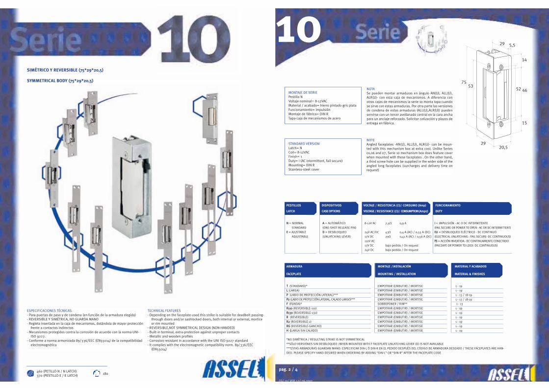
pag. 2 / 4
CG/ 10/ VER 1.0/ 06.2002
PESTILLOS DISPOSITIVOS VOLTAJE / RESISTENCIA (Ω)/ CONSUMO (Amp) FUNCIONAMIENTO
LATCH CASE OPTIONS VOLTAGE / RESISTANCE (Ω)/ CONSUMPTION (Amps) DUTY
NN = NORMAL AA = AUTOMÁTICO 8-12V AC 7,5Ω 0,9 A II = IMPULSIÓN - AC O DC INTERMITENTE
STANDARD (ONE-SHOT RELEASE PIN) (FAIL SECURE OR POWER TO OPEN - AC OR DC INTERMITTENT)EE = AJUSTABLE DD = DESBLOQUEO 24V AC/DC 43Ω 0,4 A (AC) / 0,55 A (DC) EEUU = DESBLOQUEO ELÉCTRICO - DC CONTINUO
ADJUSTABLE (UNLATCHING LEVER) 12V DC 20Ω 0,41 A (AC) / 0,56 A (DC) (ELECTRICAL UNLATCHING : FAIL SECURE- DC CONTINUOUS)
110V AC FFSS = ACCIÓN INVERTIDA - DC CONTINUAMENTE CONECTADO
12V DC bajo pedido / On request (FAILSAFE OR POWER TO LOCK- DC CONTINUOUS)
24V DC bajo pedido / On request
ARMADURA MONTAJE /INSTALACIÓN MATERIAL Y ACABADOS
FACEPLATE MOUNTING / INSTALLATION MATERIAL & FINISHES
TT (STANDARD)* EMPOTRAR (EMBUTIR) / MORTISE 1 - 19LL (LARGA) EMPOTRAR (EMBUTIR) / MORTISE 1 - 19PP (LABIO DE PROTECCIÓN LATERAL)*** EMPOTRAR (EMBUTIR) / MORTISE 1 - 13 / 18-19PP22 (LABIO DE PROTECCIÓN LATERAL, CALADO LARGO)*** EMPOTRAR (EMBUTIR) / MORTISE 1 - 13 / 18-19FF (FUNDA)* SOBREPONER / RIM** 1 - 13RR111100 (REVERSIBLE-110) EMPOTRAR (EMBUTIR) / MORTISE 1 - 19RR113300 (REVERSIBLE-130) EMPOTRAR (EMBUTIR) / MORTISE 1 - 19RR (REVERSIBLE) EMPOTRAR (EMBUTIR) / MORTISE 1 - 19RR22 (REVERSIBLE-2) EMPOTRAR (EMBUTIR) / MORTISE 1 - 19RRGG (REVERSIBLE-GANCHO) EMPOTRAR (EMBUTIR) / MORTISE 1 - 19HH ((LARGA SIN CALADO) EMPOTRAR (EMBUTIR) / MORTISE 1 - 19
*NO SIMÉTRICA / RESULTING STRIKE IS NOT SYMMETRICAL
**SÓLO VERSIONES SIN DESBLOQUEO /WHEN MOUNTED WITH F FACEPLATE UNLATCHING LEVER (D) IS NOT AVAILABLE
***ESTAS ARMADURAS GUARDAN MANO: ESPECIFICAR DIN-L Ó DIN-R EN EL PEDIDO DESPUÉS DEL CÓDIGO DE ARMADURA DESEADO / THESE FACEPLATES ARE HAN-
DED. PLEASE SPECIFY HAND DESIRED WHEN ORDERING BY ADDING “DIN-L” OR “DIN-R” AFTER THE FACEPLATE CODE
7553
29 5,5
14
46
15
52
2920,5
NOTASe pueden montar armaduras en ángulo AN(U), ALL(U),ALR(U)- con esta caja de mecanismos. A diferencia conotras cajas de mecanismos la serie 10 monta tapa cuandose sirve con estas armaduras. Por otra parte las versionesde condena de estas armaduras (ALL(U),ALR(U)) puedenservirse con un tercer avellanado central en la cara anchapara un anclaje reforzado. Solicitar cotización y plazos deentrega en fábrica.
NOTEAngled faceplates -AN(U), ALL(U), ALR(U)- can be moun-ted with this mechanism box at extra cost. Unlike Series01,06 and 07, Serie 10 mechanism box does feature coverwhen mounted with these faceplates . On the other hand,a third screw hole can be supplied in the wider side of theangled long faceplates (surcharges and delivery time onrequest)
10SIMÉTRICO Y REVERSIBLE (75*29*20,5)
SYMMETRICAL BODY (75*29*20,5)
ESPECIFICACIONES TÉCNICAS- Para puertas de paso y de condena (en función de la armadura elegida) - REVERSIBLE Y SIMÉTRICA, NO GUARDA MANO - Regleta insertada en la caja de mecanismos, dotándola de mayor protección
frente a contactos indirectos- Mecanismos protegidos contra la corrosión de acuerdo con la norma UNI-
ISO 9227.- Conforme a norma armonizada 89/336/EEC (EN55014) de la compatibilidad
electromagnética
TECHNICAL FEATURES- Depending on the faceplate used this strike is suitable for deadbolt passing-
through doors and/or sashlocked doors, both internal or external, morticeor rim mounted
- REVERSIBLE,NOT SYMMETRICAL DESIGN (NON-HANDED)- Built-in terminal, extra-protection against unproper contacts- Metallic and wooden profiles- Corrosion resistant in accordance with the UNI ISO 9227 standard- It complies with the electromagnetic compatibility norm. 89/336/EEC
(EN55014)
460 (PETILLO N / N LATCH)370 (PESTILLO E / E LATCH) 180
STANDARD VERSIONLatch= NCoil= 8-12VACFinish= 1Duty= I (AC Intermittent, fail secure)Mounting= DIN RStainless-steel cover
MONTAJE DE SERIEPestillo NVoltaje nominal= 8-12VACMaterial / acabado= hierro pintado gris plataFuncionamiento= impulsiónMontaje de fábrica= DIN RTapa-caja de mecanismos de acero
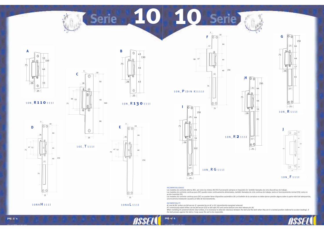
pag. 4/ 4
CG/ 10/ VER 1.0/ 06.2002
80 47
3
25
74
12
17
10
40 250
64
44
37
145
19
25
44
38
19
107
28
250
75
64
44
16
102
25
17
21
14,5
28
250
75
64
44
17
61
25
17
R
21
28
250
75
64
44
16
91
25
17
R2
21
INCOMPATIBILIDADES Los modelos de corriente alterna (AC), así como los mixtos (AC/DC) funcionarán siempre en impulsión (I). También llamados de ciclo discontinuo de trabajo .Los modelos de corriente continua pura (DC) pueden estar continuamente alimentados, también llamados de ciclo continuo de trabajo, tanto en funcionamiento normal (EU) como enacción invertida (FS).Los modelos de corriente continua pura (DC) no pueden llevar dispositivo automático (A) y el bofetón de la cerradura no debe ejercer presión alguna sobre la parte móvil del abrepuertas,una incorrecta instalación causaría un fallo de funcionamiento.
INCOMPATIBILITYAC and AC/DC strikes are fail-secure (I) -operated by an AC or DC intermittently-energized solenoid.DC continuously-rated strikes can be fail-secure (EU) or fail-safe (FS) and cannot feature one-shot release pin (A).When installing DC powered electric door strikes, it is necessary to allow for clearance between the bolt and the latch when they are in a locked position (referred to as door loading). Ifthe bolt presses against the latch, it may cause the unit to be inoperable.
10
pag. 3/ 4
CG/ 10/ VER 1 0/ 06 2002
5275
47
3
25
28
10
250
64
4452
75
47
3
25
74
12
28
10
40 250
64
44
10
53
25
75
46
66
160
44
50
3
2828
130
75
43
44
43
25
10
28
110
75
33
44
33
25
ED
C
BA
F
I
J
H
G
1 0 N _ rr 1 1 0 1 1 1 I
1 0 N A l 1 1 1 I1 0 N A h 1 1 1 I
1 0 E _ t 1 1 1 I
1 0 N _ r 1 3 0 1 1 1 I
1 0 N _ p ( D I N R ) 1 1 1 I
1 0 N _ r g 1 1 1 I
1 0 N _ f 1 1 1 I
1 0 N _ r 1 1 1 I
1 0 N _ r 2 1 1 1 I
AB
C
DE F
H
G
I
J

ESPECIFICACIONES TÉCNICAS- Para puertas de paso y de condena (en función de la armadura elegida) - REVERSIBLE Y SIMÉTRICA, NO GUARDA MANO - Regleta insertada en la caja de mecanismos, dotándola de mayor
protección frente a contactos indirectos- Para perfiles metálicos- Mecanismos protegidos contra la corrosión de acuerdo con la norma UNI-
ISO 9227.- Conforme a norma armonizada 89/336/EEC (EN55014) de la compatibilidad
electromagnética- En PVC las armaduras se montarán con tornillos especiales con rosca de
PVC, transpasando dos paredes de PVC o el refuerzo, para que la tramsmi-sión de los esfuerzos sea correcta y se eviten problemas de arrancamientode los tornillo.
TECHNICAL FEATURES- Depending on the faceplate used this strike is suitable for deadbolt passing-
through doors and/or sashlocked doors, both internal or external, morticeor rim mounted
- REVERSIBLE,NOT SYMMETRICAL DESIGN (NON-HANDED)- Built-in terminal, extra-protection against unproper contacts- Metallic and wooden profiles- Corrosion resistant in accordance with the UNI ISO 9227 standard- It complies with the electromagnetic compatibility norm. 89/336/EEC
(EN55014)- PVC Threaded screws should be fitted to the faceplate when mounting this
strike into PVC profiles. In order to avoid future tearing troubles and assurea correct transmission of efforts, fitting process require the furnishing of the strike to the metallic reinforcement of the profile or, at least, to a couple of walls of the multi-chamber profile.
MONTAJE DE SERIEPestillo EVoltaje nominal= 9-12VACMaterial / acabado= hierro pintado gris plataFuncionamiento= impulsiónMontaje de fábrica= DIN RTapa-caja de mecanismos de acero
STANDARD VERSIONLatch= ECoil= 9-12VACFinish= 1Duty= I (AC Intermittent, fail secure)Mounting= DIN RStainless-steel cover
EE = AJUSTABLE
ADJUSTABLE
PESTILLOS
LATCH
AA = AUTOMÁTICO
(ONE-SHOT RELEASE PIN)DD = DESBLOQUEO
(UNLATCHING LEVER)
VOLTAJE/RESISTENCIA (Ω)/CONSUMO (Amp)
VOLTAGE /RESISTANCE (Ω)/CONSUMPTION (Amps)
9-12V AC
24V AC/DC
12V AC/DC
12V DC
24V DC
7,5Ω
bajo pedido /
bajo pedido /
bajo pedido /
bajo pedido /
0,85 A
On request
On request
On request
On request
II = IMPULSIÓN - AC O DC INTERMITENTE
(FAIL SECURE OR POWER TO OPEN - AC OR DC INTERMITTENT)EEUU = DESBLOQUEO ELÉCTRICO - DC CONTINUO
(ELECTRICAL UNLATCHING : FAIL SECURE- DC CONTINUOUS)
FUNCIONAMIENTO
DUTY
XX (130mm)YY (LARGA SIN CALADO)ZZ (CALADO 100mm)
EMPOTRAR (EMBUTIR) / MORTISE
EMPOTRAR (EMBUTIR) / MORTISE
EMPOTRAR (EMBUTIR) / MORTISE
1-19
1-19
1-19
135300 (PESTILLO E /E LATCH)
X
2 0 E A X 1 1 1 I
2 0 E A Y 1 1 1 I
7553
5,5
14
46
15
52
2816,5
28
130
75
43
44
43
22
47
3
22
28
6,5
250
64
44
Y
75
47
3
22
100
14
28
6,5
17250
64
44
Z
2 0 E A Z 1 1 1 I
PESTILLOS
LATCH
ARMADURA
FACEPLATE
MONTAJE / INSTALACIÓN
MOUNTING / INSTALLATION
DISPOSITIVOS
CASE OPTIONS
DISPOSITIVOS
CASE OPTIONS
MATERIAL Y ACABADOS
MATERIAL& FINISHES
PERFIL EUROPEO (75*29*16,5)Caja simétrica y reversible de 16,5 mm para sistemas de aluminio y PVC de cámara de herraje de 16-17 mm (Eurocámara)
EUROPEAN PROFILE (75*29*16,5)16,5mm wide symmetrical body for narrow metallic and PVC european profiles of 16,5 to 17mm
22mm
Medida idónea parainsertar perfilesde PVC aislantesestrechos
16,5mm width willfit into PVC slimsection insulatedprofiles
Ajuste 3mm3mm adjustment
20 X
YZ
pag. 2
16,5mm
22mm
22mm

pag. 2 / 4
CG/ 60/ VER 1.0/ 06.2002
PESTILLOS DISPOSITIVOS VOLTAJE / RESISTENCIA (Ω)/ CONSUMO (Amp) FUNCIONAMIENTO
LATCH CASE OPTIONS VOLTAGE / RESISTANCE (Ω)/ CONSUMPTION (Amps) DUTY
NN = NORMAL AA = AUTOMÁTICO 8-12V AC 9Ω 0,7 A II = IMPULSIÓN - AC O DC INTERMITENTE
STANDARD (ONE-SHOT RELEASE PIN) (FAIL SECURE OR POWER TO OPEN - AC OR DC INTERMITTENT)DD = DESBLOQUEO 12V DC 70Ω 160 mA EEUU = DESBLOQUEO ELÉCTRICO - DC CONTINUO
(UNLATCHING LEVER) (ELECTRICAL UNLATCHING : FAIL SECURE- DC CONTINUOUS)
ARMADURA MONTAJE /INSTALACIÓN MATERIAL Y ACABADOS
FACEPLATE MOUNTING / INSTALLATION MATERIAL & FINISHES
LA PROPIA DE SU VERSIÓN / SOBREPONER / RIM 1
PLEASE NOTE THAT THIS STRIKE FEATURES A
SPECIAL FACEPLATE OF ITS OWN AND CAN NOT BE
SUPPLIED WITH NO OTHER TYPE OF FOREND
12
24
131
6251
62
48
20
MONTAJE DIN-L
REVERSIBILIDAD / REVERSING PROCEDURE
MONTAJE DIN-R
Desatornillar tapa y armadura, deslizar la caja de meca-nismos al otro extremo y atornillar de nuevo la tapa yla armadura
Unscrew cover and faceplate, slide release body to otherend, turn cover and faceplate around and resecure
IncompatibilidadesLos modelos de corriente alterna (AC), así como los mixtos (AC/DC) funcionarán siempre en impulsión (I). También llamados de ciclo discontinuo de trabajo.Los modelos de corriente continua pura (DC) pueden estar continuamente alimentados, también llamados de ciclo continuo de trabajo, tanto en funcionamiento normal(EU) como en acción invertida (FS).Los modelos de corriente continua pura (DC) no pueden llevar dispositivo automático (A) y el bofetón de la cerradura no debe ejercer presión alguna sobre la partemóvil del abrepuertas, una incorrecta instalación causaría un fallo de funcionamiento .
IncompatibilityWhen installing DC powered electric door strikes, it is necessary to allow for clearance between the bolt and the latch when they are in a locked position (referred to asdoor loading). If the bolt presses against the latch, it may cause the unit to be inoperable.Monitorised strikes are not available in conjuction with one-shot release pin (A).AC and AC/DC strikes are fail-secure (I) -operated by an AC or DC intermittently-energized solenoid-.DC continuously-rated strikes can be fail-secure (EU) or fail-safe (FS).
6061
61/62/63
ABREPUERTAS ELÉCTRICOS SUPERPUESTOSPARA CERRADURAS DE SOBREPONER CON CERROJO
RIM STRIKES FOR VERTICAL AND HORIZONTALSURFACE SASHLOCKS
61/62/63
CARACTERÍSTICAS TÉCNICAS- Conforme a norma armonizada 89/336/EEC (EN55014) de la compatibili-
dad electromagnética especificaciones técnicas- Regleta insertada en la caja de mecanismos, dotándola de mayor protec-
ción frente a contactos indirectos - Mecanismos protegidos contra la corrosión de acuerdo con la norma UNI-
ISO 9227.
TECHNICAL FEATURES- Protected buil-in terminal- Corrosion resistant in accordance with the UNI ISO 9227 standard- It complies with the electromagnetic compatibility norm. 89/336/EEC
(EN55014)
300 625
61
63 62
6 1 N _ 1 1 1 I

pag. 4 / 4
CG/ 60/ VER 1.0/ 06.2002
62
44
36,4
7
53
195,5
70
10
2894
8
8
112
46
46
5,5
26,5
10
Abrepuertas para Cerraduras de Sobreponer dotadasde Cerrojo, tanto Horizontales como Verticales
Acepta dos montajes posibles:DIN-R con el alojamiento para el cerrojo hacia abajoDIN-L con el alojamiento para el cerrojo hacia arriba
Compatible con cerraduras de sobreponer para puertas de maderadel tipo:AZBE: 6, 7, 125CVL: 122A, 125A, 56A, 56BLINCE: 5056, 5125MCM: 2525, 2556A
Rim type Electric Strike for use with both Horizontal andVertical Surface-mounted Sashlocks
2 different mounting possibilities are available:DIN-R: latch is under the deadbolt housingDIN-L: latch is over the deadbolt housing
Lock compatibility:AZBE: 6, 7, 125CVL: 122A, 125A, 56A, 56BLINCE: 5056, 5125MCM: 2525, 2556A
ARMADURA MONTAJE /INSTALACIÓN MATERIAL Y ACABADOS
FACEPLATE MOUNTING / INSTALLATION MATERIAL & FINISHES
LA PROPIA DE SU VERSIÓN / SOBREPONER / RIM 1,4,7
PLEASE NOTE THAT THIS STRIKE FEATURES A
SPECIAL FACEPLATE OF ITS OWN AND CAN NOT BE
SUPPLIED WITH NO OTHER TYPE OF FOREND
* ESTA VERSIÓN ACEPTA DOS MONTAJES POSIBLES: DIN-LEFT CON EL CERROJO ARRIBA Y DIN-R CON EL CERROJO DEBAJO
* TWO DIFFERENT MOUNTING POSSIBILITIES ARE AVAILABLE: DIN-LEFT (LATCH IS UNDER THE DEADBOLT HOUSING) OR DIN-RIGHT (LATCH IS OVER
THE DEADBOLT HOUSING)
PESTILLOS DISPOSITIVOS VOLTAJE / RESISTENCIA (Ω)/ CONSUMO (Amp) FUNCIONAMIENTO
LATCH CASE OPTIONS VOLTAGE / RESISTANCE (Ω)/ CONSUMPTION (Amps) DUTY
NN = NORMAL 8-12V AC 9Ω 0,7 A II = IMPULSIÓN - AC O DC INTERMITENTE
STANDARD (FAIL SECURE OR POWER TO OPEN - AC OR DC INTERMITTENT)
24V AC/DC 70Ω 220 mA (AC) EEUU = DESBLOQUEO ELÉCTRICO - DC CONTINUO
70Ω 340 mA (DC) (ELECTRICAL UNLATCHING : FAIL SECURE- DC CONTINUOUS)
12V AC/DC 30Ω 0,3 A (AC) FFSS = ACCIÓN INVERTIDA - DC CONTINUAMENTE CONECTADO
30Ω 0,4 A (DC) (FAILSAFE OR POWER TO LOCK- DC CONTINUOUS)
110V AC* - -
12V DC 70Ω 160 mA
24V DC 170Ω 140 mA
* SÓLO PARA PAÍSES DONDE ESTÁ PERMITIDA ESTA TENSIÓN. POR RAZONES DE SEGURIDAD LOS ABREPUERTAS PREPARADOS PARA TRABAJAR EN ESTA TENSIÓN INCORPO-
RAN UN TORNILLO ESPECIAL PARA SU CONEXIÓN A UNA TOMA DE TIERRA.
*TO BE USED ONLY WITHIN THOSE COUNTRIES WHERE THIS VOLTAGE IS LEGALLY ALLOWED. FOR SAFETY REASONS STRIKES WORKING AT 110VAC FEATURE A SPECIAL BUILT-IN
SCREW FOR EARTH CONNECTION.
6061/62/63
63
pag. 3 / 4
CG/ 60/ VER 1.0/ 06.2002
62
44
36,4
7
53
195,5
70
10
2894
8
8
112
46
46
5,5
26,5
10
DIN L
ARMADURA MONTAJE /INSTALACIÓN MATERIAL Y ACABADOS
FACEPLATE MOUNTING / INSTALLATION MATERIAL & FINISHES
LA PROPIA DE SU VERSIÓN / SOBREPONER / RIM 1,4,7
PLEASE NOTE THAT THIS STRIKE FEATURES A
SPECIAL FACEPLATE OF ITS OWN AND CAN NOT BE
SUPPLIED WITH NO OTHER TYPE OF FOREND
* ESTA VERSIÓN ACEPTA DOS MONTAJES POSIBLES: DIN-LEFT CON EL CERROJO DEBAJO Y DIN-R CON EL CERROJO ARRIBA
* TWO DIFFERENT MOUNTING POSSIBILITIES ARE AVAILABLE: DIN-LEFT (LATCH IS OVER THE DEADBOLT HOUSING) OR DIN-RIGHT (LATCH IS UNDER
THE DEADBOLT HOUSING)
PESTILLOS DISPOSITIVOS VOLTAJE / RESISTENCIA (Ω)/ CONSUMO (Amp) FUNCIONAMIENTO
LATCH CASE OPTIONS VOLTAGE / RESISTANCE (Ω)/ CONSUMPTION (Amps) DUTY
NN = NORMAL 8-12V AC 9Ω 0,7 A II = IMPULSIÓN - AC O DC INTERMITENTE
STANDARD (FAIL SECURE OR POWER TO OPEN - AC OR DC INTERMITTENT)
24V AC/DC 70Ω 220 mA (AC) EEUU = DESBLOQUEO ELÉCTRICO - DC CONTINUO
70Ω 340 mA (DC) (ELECTRICAL UNLATCHING : FAIL SECURE- DC CONTINUOUS)
12V AC/DC 30Ω 0,3 A (AC) FFSS = ACCIÓN INVERTIDA - DC CONTINUAMENTE CONECTADO
30Ω 0,4 A (DC) (FAILSAFE OR POWER TO LOCK- DC CONTINUOUS)
110V AC* - -
12V DC 70Ω 160 mA
24V DC 170Ω 140 mA
* SÓLO PARA PAÍSES DONDE ESTÁ PERMITIDA ESTA TENSIÓN. POR RAZONES DE SEGURIDAD LOS ABREPUERTAS PREPARADOS PARA TRABAJAR EN ESTA TENSIÓN INCORPO-
RAN UN TORNILLO ESPECIAL PARA SU CONEXIÓN A UNA TOMA DE TIERRA.
*TO BE USED ONLY WITHIN THOSE COUNTRIES WHERE THIS VOLTAGE IS LEGALLY ALLOWED. FOR SAFETY REASONS STRIKES WORKING AT 110VAC FEATURE A SPECIAL BUILT-IN
SCREW FOR EARTH CONNECTION.
6061/62/63
62Abrepuertas para Cerraduras de Sobreponer dotadasde Cerrojo, tanto Horizontales como Verticales
Acepta dos montajes posibles:DIN-L con el alojamiento para el cerrojo hacia abajoDIN-R con el alojamiento para el cerrojo hacia arriba
Compatible con cerraduras de sobreponer para puertas de maderadel tipo:AZBE: 6, 7, 125CVL: 122A, 125A, 56A, 56BLINCE: 5056, 5125MCM: 2525, 2556A
Rim type Electric Strike for use with both Horizontal andVertical Surface-mounted Sashlocks
2 different mounting possibilities are available:DIN-L : latch is under the deadbolt housingDIN-R : latch is over the deadbolt housing
Lock compatibility:AZBE: 6, 7, 125CVL: 122A, 125A, 56A, 56BLINCE: 5056, 5125MCM: 2525, 2556A
6 2 N _ 1 1 1 I
6 3 N _ 1 1 1 I

pag. 2 / 2
CG/ comp/ VER 1.0/ 06.2002
52,5
44,5
35
7
33
30
20
62
15
13
62
ACCESORIOS COMPLEMENTARIOS-Doble Contacto Puerta-Transformador (entrada 125-220v; salida 12v)-Transformador (entrada 220v; salida 12v)-Cables rizados para telefonía. Se suministran bajo pedido y características defini-
das por el cliente (longitud, diámetro de rizo, cables interiores,etc.)
NOTA: Se pueden servir transformadores de tensiones especiales de salida o nonormalizadas de entrada. Consultar con fábrica.
ACCESSORIES -DOUBLE DOOR CONTACT-Transformer (input 125-220v; output 12v)-Transformer (input 220v; output 12v)- Rolling wires for video-telephony devices. Supplied on demand. Length, diameter
of loop, internal wires,etc. to be defined by customer.
N.B.: Special input/output voltage transformers available on request
ref.:1521 (125-220VAC; 12VDC)1522 (220VAC; 12VDC)
ref.:1511
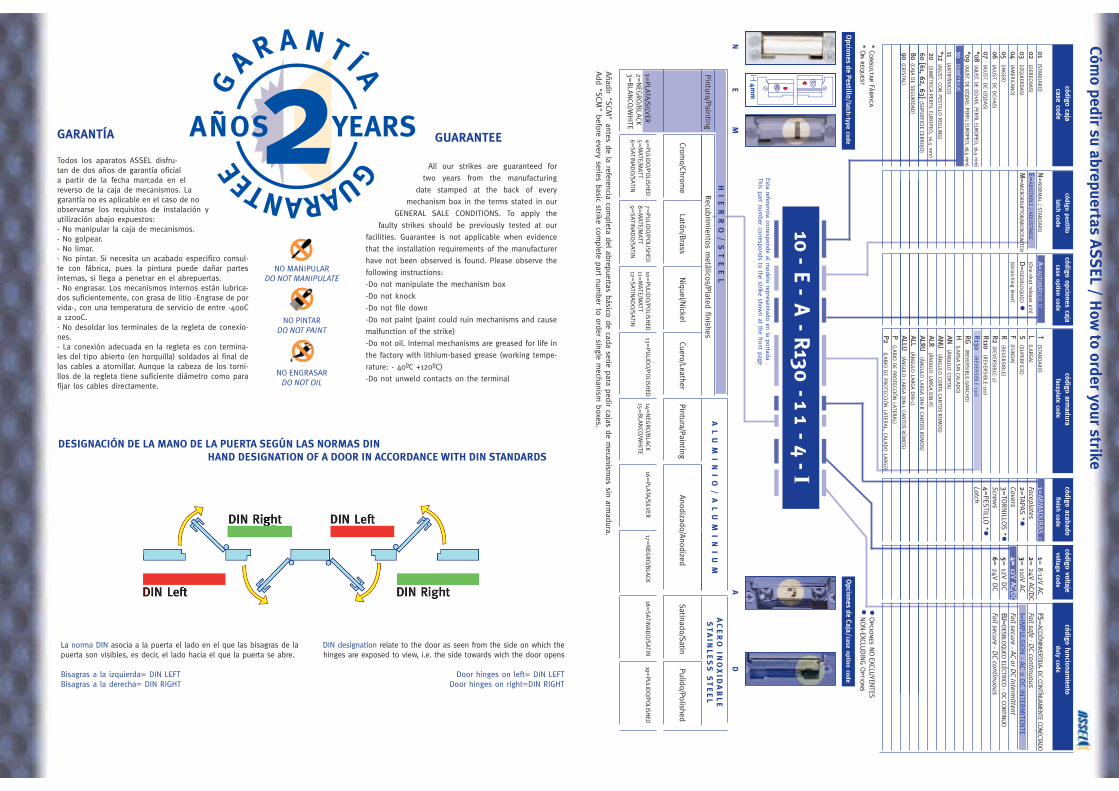
GARANTÍA
Todos los aparatos ASSEL disfru-tan de dos años de garantía oficiala partir de la fecha marcada en elreverso de la caja de mecanismos. Lagarantía no es aplicable en el caso de noobservarse los requisitos de instalación yutilización abajo expuestos:- No manipular la caja de mecanismos.- No golpear.- No limar.- No pintar. Si necesita un acabado especifico consul-te con fábrica, pues la pintura puede dañar partesinternas, si llega a penetrar en el abrepuertas.- No engrasar. Los mecanismos internos están lubrica-dos suficientemente, con grasa de litio -Engrase de porvida-, con una temperatura de servicio de entre -40oCa 120oC.- No desoldar los terminales de la regleta de conexio-nes.- La conexión adecuada en la regleta es con termina-les del tipo abierto (en horquilla) soldados al final delos cables a atornillar. Aunque la cabeza de los torni-llos de la regleta tiene suficiente diámetro como parafijar los cables directamente.
GUARANTEE
All our strikes are guaranteed for
two years from the manufacturing
date stamped at the back of every
mechanism box in the terms stated in our
GENERAL SALE CONDITIONS. To apply the
faulty strikes should be previously tested at our
facilities. Guarantee is not applicable when evidence
that the installation requirements of the manufacturer
have not been observed is found. Please observe the
following instructions:
-Do not manipulate the mechanism box
-Do not knock
-Do not file down
-Do not paint (paint could ruin mechanisms and cause
malfunction of the strike)
-Do not oil. Internal mechanisms are greased for life in
the factory with lithium-based grease (working tempe-
rature: - 40ºC +120ºC)
-Do not unweld contacts on the terminal
DESIGNACIÓN DE LA MANO DE LA PUERTA SEGÚN LAS NORMAS DINHAND DESIGNATION OF A DOOR IN ACCORDANCE WITH DIN STANDARDS
La norma DIN asocia a la puerta el lado en el que las bisagras de lapuerta son visibles, es decir, el lado hacia el que la puerta se abre.
Bisagras a la izquierda= DIN LEFTBisagras a la derecha= DIN RIGHT
DIN designation relate to the door as seen from the side on which thehinges are exposed to view, i.e. the side towards wich the door opens
Door hinges on left= DIN LEFTDoor hinges on right=DIN RIGHT
NO PINTARDO NOT PAINT
NO ENGRASARDO NOT OIL
NO MANIPULARDO NOT MANIPULATE
código caja código pestillocódigo opciones caja código arm
adura código acabado código voltaje código funcionamiento
case code latch code case option code faceplate code finish code voltage code duty code
01(STA
NDARD)
N=
NORM
AL
/ STANDARD
A=AU
TOM
ÁTICO
cT
(STANDARD)
1=ARM
ADURAS c
1= 8-12V
ACFS
=ACCIÓ
NINVERTIDA- DC CONTÍNUAM
ENTE CONECTADO
02(D
ERECH
AS)
E=AJU
STABLE / A
DJU
STABLE
(One-shot release pin)
L(LA
RGA)
Faceplates2=
24V AC/D
CFail safe - D
C continuous03
(IZQUIER
DAS)
M=
MICRO
RRUPTO
R/MICRO
SWITCH
D=
DESB
LOQUEO
S(SU
PERFICIE)
2=TA
PAS *
3= 110V
ACI=
IMPULSIO
N - AC o D
C INTER
MITEN
TE04
(AM
ERICA
NO)
(Unlatching lever)
F(FU
NDA)
Covers4=
12V AAC/D
CFail secure - AC or D
C intermittent
05(IN
GER
)R
(REV
ERSIB
LE)3=
TORNILLO
S *5=
12V D
CEU
=DESBLO
QUEO
ELÉCTRICO - D
C CONTIN
UO06
(AJU
ST. DE D
CHAS)
R2(R
EVER
SIBLE-2)
Screws
6= 24V
DC
Fail secure - DC continuous
07(A
JUST. D
E IZQDAS)
R110(R
EVER
SIBLE-110)
4=PESTILLO
**08
(AJUST. D
E DCH
AS. PERFILEU
ROPEO
, 16,5 mm
)R130
(REV
ERSIB
LE-130)Latch
*09(AJUST. D
E IZQDAS. PERFIL
EUROPEO
, 16,5 mm
)RG
(REV
ERSIB
LE-GANCH
O)
10(SIM
ÉTRICA
)H
(LARG
ASIN
CALA
DO)
11(A
NTIP
ÁNICO
)AN
(ÁNGULO
CORTA
)
*12(A
JUST. CO
N PESTILLO
ROLLIN
G)
ANU
(ÁNGULO
CORTA
CANTO
SRO
MOS)
20(SIM
ÉTRICA
PERFIL
EURO
PEO, 16,5 m
m)
ALR(Á
NGULO
LARG
ADIN
-R)
60 [[61, 662, 663](SU
PERFICIE
CERRO
JO)
ALRU(Á
NGULO
LARG
ADIN
-R CA
NTO
SRO
MOS)
80(CA
JADE SEG
URID
AD)
ALL(Á
NGULO
LARG
ADIN
-L)
90(CR
ISTAL)
ALLU(Á
NGULO
LARG
ADIN
-LCA
NTO
SRO
MOS)
P (LABIO
DE P
ROTECCIÓ
N LATER
AL)
P2(LA
BIO
DE P
ROTECCIÓ
N LATER
AL, CA
LADO LA
RGO)
HI
ER
RO
/S
TE
EL
AL
UM
IN
IO
/A
LU
MI
NI
UM
Pintura/PaintingAnodizado/A
nodizedSatinado/Satin
Pulido/Polished
AC
ER
OIN
OX
IDA
BL
ES
TA
INL
ES
S S
TE
EL
Pintura/PaintingRecubrim
ientos metálicos/Plated finishes
1=PLATA
/SILVER
2=NEG
RO/B
LACK3=
BLA
NCO
/WHITE
4=PU
LIDO/P
OLISH
ED5=
MATE/M
ATT6=
SATINADO/SATIN
7=PULID
O/PO
LISHED
8=M
ATE/MATT
9=SATIN
ADO/SATIN
10=PULID
O/PO
LISHED
11=M
ATE/MATT
12=SATIN
ADO/SATIN
13=PULID
O/P
OLISH
ED14=
NEG
RO/B
LACK15=
BLA
NCO
/WHITE
16=PLATA
/SILVER
17=NEG
RO/B
LACK18=
SATINADO/SATIN
19=PU
LIDO/PO
LISHED
Cromo/Chrom
eLatón/B
rassNiquel/N
ickelCuero/Leather
10 -E -
A- R
130-1 1
- 4 - I
4m
m
Opciones de Pestillo/latch-type code
Opciones de Caja/case option code
NE
MA
D
Cómo pedir su abrepuertas A
SS
EL/ H
ow to order your strike
Esta referencia corresponde al modelo representado en la portada
This part number corresponds to the strike show
n at the front page
Opciones N
OEXCLU
YENTES
NON-EXCLU
DIN
G O
ptions*
Consultar Fábrica*
On request
Añadir "SCM
" antes de la referencia completa del abrepuertas básico de cada serie para pedir cajas de m
ecanismos sin arm
adura.Add "SCM
" before every series basic strike complete part num
ber to order single mechanism
boxes.
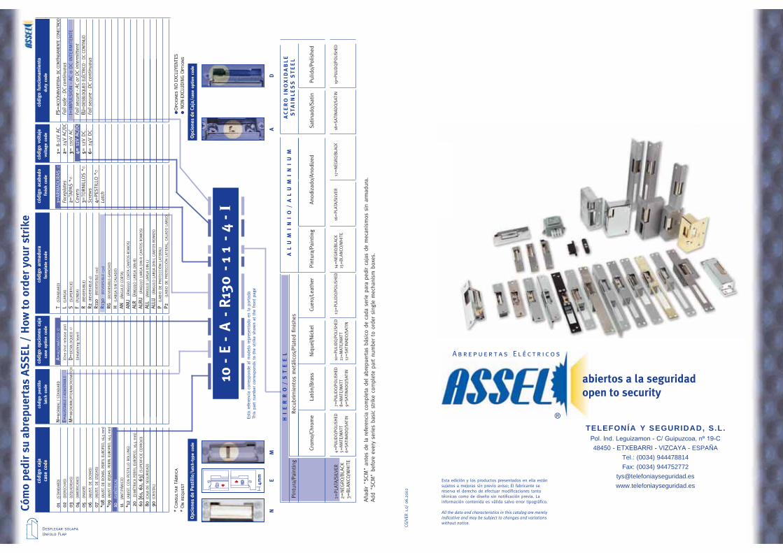
TELEFONÍA Y SEGURIDAD, S.L.
48 - - ESPAÑATel.: (0034) 944478814Fax: (0034) 944752772
Esta edición y los productos presentados en ella estánsujetos a mejoras sin previo aviso; El fabricante sereserva el derecho de efectuar modificaciones tantotécnicas como de diseño sin notificación previa. Lainformación contenida es válida salvo error tipográfico.
All the data and characteristics in this catalog are merelyindicative and may be subject to changes and variationswithout notice.
CG/V
ER1.
0/06
.200
2
Abre p u e r t a s E l é c t r i c o s
®
códi
goca
jacó
digo
pest
illo
códi
goop
cion
esca
jacó
digo
arm
adur
acó
digo
acab
ado
códi
govo
ltaje
códi
gofu
ncio
nam
ient
oca
seco
dela
tch
code
case
optio
nco
defa
cepl
ate
code
finis
hco
devo
ltage
code
duty
code
01(S
TANDARD)
N=
NORM
AL
/ ST
ANDARD
A =AU
TOM
ÁTI
COc
T(S
TANDARD)
1 =ARM
ADURAS c
1= 8
-12V
AC
FS=
ACCIÓNI
NVER
TIDA
- DC
CONT
ÍNUA
MEN
TE C
ONE
CTAD
O02
(DER
ECHAS)
E =AJU
STABLE
/ A
DJU
STABLE
(One
-sho
t re
leas
e pi
n)L
(LARG
A)
Face
plat
es2=
24V
AC/
DC
Fail
safe
- D
C co
ntin
uous
03(IZQ
UIE
RDAS)
M=
MIC
RORR
UPT
OR/
MIC
ROSW
ITCH
D=
DES
BLO
QUEOc
S(S
UPE
RFI
CIE)
2 =TA
PAS
*c3=
110
V A
CI =
IMPULS
ION -
AC
o DC
INTE
RM
ITEN
TE04
(AM
ERIC
ANO)
(Unl
atch
ing
leve
r)F
(FUNDA)
Cove
rs4=
12V
AAC/D
CFa
il se
cure
- AC
or
DC
inte
rmit
tent
05(INGER
)R
(REV
ERSI
BLE
)3 =
TORNIL
LOS
*c5=
12V
DC
EU=
DES
BLOQUE
O E
LÉCT
RICO
- DC
CONTINUO
06(A
JUST
. DE
DCH
AS)
R2(R
EVER
SIBLE
-2)
Scre
ws
6= 2
4V D
CFa
il se
cure
- D
C co
ntin
uous
07(A
JUST
. DE
IZQDAS)
R110
(REV
ERSI
BLE
-110
)4 =
PEST
ILLO
*c
*08
(AJU
ST. D
E DCH
AS. P
ERFIL
EURO
PEO, 1
6,5
mm
)R1
30(R
EVER
SIBLE
-130
)La
tch
*09
(AJU
ST. D
E IZQDAS
. PER
FIL
EURO
PEO, 1
6,5
mm
)RG
(REV
ERSI
BLE
-GANCH
O)
10(S
IMÉT
RIC
A)
H(L
ARG
ASI
NCA
LADO)
11(A
NTI
PÁNIC
O)
AN(Á
NGULO
CORT
A)
*12
(AJU
ST. CO
N P
ESTI
LLO R
OLL
ING)
ANU
(ÁNGULO
CORT
ACA
NTO
SRO
MOS)
20(S
IMÉT
RIC
APE
RFI
LEU
ROPE
O, 16
,5 m
m)
ALR
(ÁNGULO
LARG
ADIN
-R)
60 [[61
, 662
, 663
](S
UPE
RFI
CIE
CERRO
JO)
ALRU
(ÁNGULO
LARG
ADIN
-R C
ANTO
SRO
MOS)
80(C
AJA
DE
SEGURID
AD)
ALL
(ÁNGULO
LARG
ADIN
-L)
90(C
RIS
TAL)
ALLU
(ÁNGULO
LARG
ADIN
-LCA
NTO
SRO
MOS)
P (
LABIO
DE
PRO
TECC
IÓN L
ATER
AL)
P2(L
ABIO
DE
PRO
TECC
IÓN L
ATER
AL,
CALA
DO L
ARG
O)
HI
ER
RO
/S
TE
EL
AL
UM
IN
IO
/A
LU
MI
NI
UM
Pint
ura/
Pain
ting
Ano
diza
do/A
nodi
zed
Satina
do/S
atin
Pulid
o/Po
lishe
d
AC
ER
OIN
OX
IDA
BL
ES
TA
INL
ES
S S
TE
EL
Pint
ura/
Pain
ting
Recu
brim
ient
os m
etál
icos
/Pla
ted
finis
hes
1=PLA
TA/S
ILVER
2=NEG
RO/B
LACK
3=BLA
NCO
/WHIT
E
4=PU
LIDO/P
OLI
SHED
5=M
ATE/
MAT
T6=
SATI
NADO/S
ATIN
7=PULI
DO/P
OLI
SHED
8=M
ATE/
MAT
T9=
SATI
NADO/S
ATIN
10=PULI
DO/P
OLI
SHED
11=M
ATE/
MAT
T12
=SA
TINADO/S
ATIN
13=PULI
DO/P
OLI
SHED
14=NEG
RO/B
LACK
15=BLA
NCO
/WHIT
E16
=PLA
TA/S
ILVER
17=NEG
RO/B
LACK
18=SA
TINADO/S
ATIN
19=PU
LIDO/P
OLI
SHED
Crom
o/Ch
rom
eLa
tón/
Bra
ssNiq
uel/N
icke
lCu
ero/
Leat
her
10 -
E -
A-
R13
0-1
1-
4 - I
4m
m
Opc
ione
s de
Pes
till
o/la
tch-
type
cod
e O
pcio
nes
de C
aja/
case
opt
ion
code
NE
MA
D
Cóm
o pe
dir
su a
brep
uert
as A
SS
EL/
How
to
orde
r yo
ur s
trik
e
Esta
ref
eren
cia
corres
pond
e al
mod
elo
repr
esen
tado
en
la p
orta
daTh
is p
art
num
ber
corres
pond
s to
the
strik
e sh
own
at t
he fro
nt p
age
Opc
ione
s NO
EXCL
UYE
NTE
SNON-E
XCLU
DIN
G O
ptio
ns*
Cons
ulta
r Fá
bric
a*
On
requ
est
Aña
dir
"SCM
" an
tes
de la
refe
renc
ia c
ompl
eta
del ab
repu
erta
s bá
sico
de
cada
ser
ie p
ara
pedi
r ca
jas
de m
ecan
ism
os s
in a
rmad
ura.
Add
"SCM
" be
fore
eve
ry s
erie
s ba
sic
strike
com
plet
e pa
rt n
umbe
r to
ord
er s
ingl
e m
echa
nism
box
es.
Desplegar solapaUnfold Flap
abiertos a la seguridadopen to security