
Evaluación y mejoramiento de la calidad de la...
16
(Recibido: Noviembre 17 de 2010 - Aceptado: Mayo 18 de 2011) Resumen Las aplicaciones prácticas, tales como la incorporación de un nuevo enfoque teórico en la definición de estrategias de compensación instantánea y promediada para filtros activos de potencia en sistemas polifásicos y la descripción de un indicador global para la evaluación de la calidad de potencia, son introducidas en este artículo. Para alcanzar estas aplicaciones, una teoría generalizada de la potencia instantánea aplicada en sistemas no-sinusoidales, polifásicos y asimétricos es propuesta. El tensor de potencia instantánea se define en función del producto tensorial entre los vectores de tensión y corriente. Además, resultados simulados son incluidos. Palabras clave: Compensador Activo de Potencia, Teoría de Potencia Instantánea, Sistemas Polifásicos, Producto tensorial Abstract Practical applications, such as the incorporation of the a new theoretical approach in the definition of the instantaneous and average compensation objectives for active power filters (APFs) in multiphase systems and the description of a global indicator for the evaluation of the power quality are introduced in this paper. In order to obtain these applications, a generalized theory of instantaneous power for nonsinusoidal unbalanced multiphase systems is proposed. The instantaneous power tensor is defined based on the tensor product between vectors of voltage and current. In addition, the simulated results are included. Active Power Compensator, Instantaneous Power Theory, Multiphase Systems, Tensor product Keywords: INGENIERÍA ELÉCTRICA Evaluación y mejoramiento de la calidad de la potencia eléctrica usando un nuevo enfoque teórico Improvement and assessment of the electrical power quality using a new theoretical approach ELECTRICAL ENGINEERING 1§ 2 3 Armando J. Ustariz-Farfan , Eduardo A. Cano-Plata , Hernán E. Tacca 1 Department of Electrical, Electronic and Computer Engineering, Universidad Nacional de Colombia, Manizales, [email protected] § 2 Department of Electrical, Electronic and Computer Engineering, Universidad Nacional de Colombia, Manizales, [email protected] 3 Department of Electronic Engineering, Universidad de Buenos Aires, Buenos Aires Argentina, [email protected]. 97 Ingeniería y Competitividad, Volumen 13, No. 1, p. 97 - 112 (2011)
Transcript of Evaluación y mejoramiento de la calidad de la...

(Recibido: Noviembre 17 de 2010 - Aceptado: Mayo 18 de 2011)
Resumen
Las aplicaciones prácticas, tales como la incorporación de un nuevo enfoque teórico en la definición de estrategias de compensación instantánea y promediada para filtros activos de potencia en sistemas polifásicos y la descripción de un indicador global para la evaluación de la calidad de potencia, son introducidas en este artículo. Para alcanzar estas aplicaciones, una teoría generalizada de la potencia instantánea aplicada en sistemas no-sinusoidales, polifásicos y asimétricos es propuesta. El tensor de potencia instantánea se define en función del producto tensorial entre los vectores de tensión y corriente. Además, resultados simulados son incluidos.
Palabras clave: Compensador Activo de Potencia, Teoría de Potencia Instantánea, Sistemas Polifásicos, Producto
tensorial
Abstract
Practical applications, such as the incorporation of the a new theoretical approach in the definition of the instantaneous and average compensation objectives for active power filters (APFs) in multiphase systems and the description of a global indicator for the evaluation of the power quality are introduced in this paper. In order to obtain these applications, a generalized theory of instantaneous power for nonsinusoidal unbalanced multiphase systems is proposed. The instantaneous power tensor is defined based on the tensor product between vectors of voltage and current. In addition, the simulated results are included.
Active Power Compensator, Instantaneous Power Theory, Multiphase Systems, Tensor productKeywords:
INGENIERÍA ELÉCTRICA
Evaluación y mejoramiento de la calidad de la potencia
eléctrica usando un nuevo enfoque teórico
Improvement and assessment of the electrical
power quality using a new theoretical approach
ELECTRICAL ENGINEERING
1§ 2 3Armando J. Ustariz-Farfan , Eduardo A. Cano-Plata , Hernán E. Tacca1 Department of Electrical, Electronic and Computer Engineering, Universidad Nacional de Colombia,
Manizales, [email protected]
§
2 Department of Electrical, Electronic and Computer Engineering, Universidad Nacional de Colombia, Manizales, [email protected]
3Department of Electronic Engineering, Universidad de Buenos Aires, Buenos Aires Argentina, [email protected].
97
Ingeniería y Competitividad, Volumen 13, No. 1, p. 97 - 112 (2011)
1. Introduction
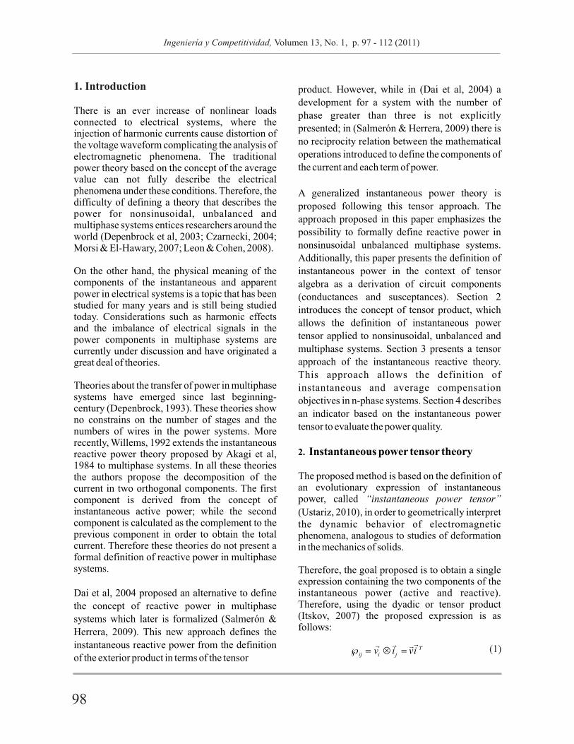
There is an ever increase of nonlinear loads connected to electrical systems, where the injection of harmonic currents cause distortion of the voltage waveform complicating the analysis of electromagnetic phenomena. The traditional power theory based on the concept of the average value can not fully describe the electrical phenomena under these conditions. Therefore, the difficulty of defining a theory that describes the power for nonsinusoidal, unbalanced and multiphase systems entices researchers around the world (Depenbrock et al, 2003; Czarnecki, 2004; Morsi & El-Hawary, 2007; Leon & Cohen, 2008).
On the other hand, the physical meaning of the components of the instantaneous and apparent power in electrical systems is a topic that has been studied for many years and is still being studied today. Considerations such as harmonic effects and the imbalance of electrical signals in the power components in multiphase systems are currently under discussion and have originated a great deal of theories.
Theories about the transfer of power in multiphase systems have emerged since last beginning-century (Depenbrock, 1993). These theories show no constrains on the number of stages and the numbers of wires in the power systems. More recently, Willems, 1992 extends the instantaneous reactive power theory proposed by Akagi et al, 1984 to multiphase systems. In all these theories the authors propose the decomposition of the current in two orthogonal components. The first component is derived from the concept of instantaneous active power; while the second component is calculated as the complement to the previous component in order to obtain the total current. Therefore these theories do not present a formal definition of reactive power in multiphase systems.
Dai et al, 2004 proposed an alternative to define
the concept of reactive power in multiphase
systems which later is formalized (Salmerón &
Herrera, 2009). This new approach defines the
instantaneous reactive power from the definition
of the exterior product in terms of the tensor
product. However, while in (Dai et al, 2004) a
development for a system with the number of
phase greater than three is not explicitly
presented; in (Salmerón & Herrera, 2009) there is
no reciprocity relation between the mathematical
operations introduced to define the components of
the current and each term of power.
A generalized instantaneous power theory is
proposed following this tensor approach. The
approach proposed in this paper emphasizes the
possibility to formally define reactive power in
nonsinusoidal unbalanced multiphase systems.
Additionally, this paper presents the definition of
instantaneous power in the context of tensor
algebra as a derivation of circuit components
(conductances and susceptances). Section 2
introduces the concept of tensor product, which
allows the definition of instantaneous power
tensor applied to nonsinusoidal, unbalanced and
multiphase systems. Section 3 presents a tensor
approach of the instantaneous reactive theory.
This approach allows the definition of
instantaneous and average compensation
objectives in n-phase systems. Section 4 describes
an indicator based on the instantaneous power
tensor to evaluate the power quality.
2. Instantaneous power tensor theory
The proposed method is based on the definition of an evolutionary expression of instantaneous power, called “instantaneous power tensor”
(Ustariz, 2010), in order to geometrically interpret the dynamic behavior of electromagnetic phenomena, analogous to studies of deformation in the mechanics of solids.
Therefore, the goal proposed is to obtain a single expression containing the two components of the instantaneous power (active and reactive). Therefore, using the dyadic or tensor product (Itskov, 2007) the proposed expression is as follows:
?
nFigure 1: Multiphase system of n-phase and m-wire, R
98 99
Ingeniería y Competitividad, Volumen 13, No. 1, p. 97 - 112 (2011) Ingeniería y Competitividad, Volumen 13, No. 1, p. 97 - 112 (2011)
1. Introduction
There is an ever increase of nonlinear loads connected to electrical systems, where the injection of harmonic currents cause distortion of the voltage waveform complicating the analysis of electromagnetic phenomena. The traditional power theory based on the concept of the average value can not fully describe the electrical phenomena under these conditions. Therefore, the difficulty of defining a theory that describes the power for nonsinusoidal, unbalanced and multiphase systems entices researchers around the world (Depenbrock et al, 2003; Czarnecki, 2004; Morsi & El-Hawary, 2007; Leon & Cohen, 2008).
On the other hand, the physical meaning of the components of the instantaneous and apparent power in electrical systems is a topic that has been studied for many years and is still being studied today. Considerations such as harmonic effects and the imbalance of electrical signals in the power components in multiphase systems are currently under discussion and have originated a great deal of theories.
Theories about the transfer of power in multiphase systems have emerged since last beginning-century (Depenbrock, 1993). These theories show no constrains on the number of stages and the numbers of wires in the power systems. More recently, Willems, 1992 extends the instantaneous reactive power theory proposed by Akagi et al, 1984 to multiphase systems. In all these theories the authors propose the decomposition of the current in two orthogonal components. The first component is derived from the concept of instantaneous active power; while the second component is calculated as the complement to the previous component in order to obtain the total current. Therefore these theories do not present a formal definition of reactive power in multiphase systems.
Dai et al, 2004 proposed an alternative to define
the concept of reactive power in multiphase
systems which later is formalized (Salmerón &
Herrera, 2009). This new approach defines the
instantaneous reactive power from the definition
of the exterior product in terms of the tensor
product. However, while in (Dai et al, 2004) a
development for a system with the number of
phase greater than three is not explicitly
presented; in (Salmerón & Herrera, 2009) there is
no reciprocity relation between the mathematical
operations introduced to define the components of
the current and each term of power.
A generalized instantaneous power theory is
proposed following this tensor approach. The
approach proposed in this paper emphasizes the
possibility to formally define reactive power in
nonsinusoidal unbalanced multiphase systems.
Additionally, this paper presents the definition of
instantaneous power in the context of tensor
algebra as a derivation of circuit components
(conductances and susceptances). Section 2
introduces the concept of tensor product, which
allows the definition of instantaneous power
tensor applied to nonsinusoidal, unbalanced and
multiphase systems. Section 3 presents a tensor
approach of the instantaneous reactive theory.
This approach allows the definition of
instantaneous and average compensation
objectives in n-phase systems. Section 4 describes
an indicator based on the instantaneous power
tensor to evaluate the power quality.
2. Instantaneous power tensor theory
The proposed method is based on the definition of an evolutionary expression of instantaneous power, called “instantaneous power tensor”
(Ustariz, 2010), in order to geometrically interpret the dynamic behavior of electromagnetic phenomena, analogous to studies of deformation in the mechanics of solids.
Therefore, the goal proposed is to obtain a single expression containing the two components of the instantaneous power (active and reactive). Therefore, using the dyadic or tensor product (Itskov, 2007) the proposed expression is as follows:
?
nFigure 1: Multiphase system of n-phase and m-wire, R
98 99
Ingeniería y Competitividad, Volumen 13, No. 1, p. 97 - 112 (2011) Ingeniería y Competitividad, Volumen 13, No. 1, p. 97 - 112 (2011)

Given these possible compensation objective, the
instantaneous vector of the referent current is
defined as:
Moreover, of the various options of the reference
tensor shown in Table 1, is the variable term
of the instantaneous active power tensor defined
by:
Where G is the equivalent conductance tensor ?
defined by:
With defined as the “Kronecker's delta tensor” ?
and used to construct the equivalent conductance
tensor. While is the variable term of
instantaneous reactive power, defined as:
where B is the equivalent susceptance tensor ?
defined by:
The block diagram of the control strategies for the
determination of APF reference compensation
currents is shown in Figure 2, where the
compensation objectives selector block was
implemented.
and in Ec. (11) is the instantaneous susceptance
tensor:
Moreover, the decomposition of the instantaneous
current vector is characterized by:
such that,
3.2 Orthogonal decomposition of the power
tensor
The decomposition of the instantaneous power
tensor is obtained by applying the tensor product
of the voltage vector on Ec. (9) , thus:
Here, the first term is the instantaneous active
power tensor:
and the second term is the instantaneous reactive
power tensor:
Consequently,
Moreover, Ec. (19) satisfies the orthogonality
concept, in other words,
Here, the tr operator corresponds to the sum of the
main diagonal elements (trace). Therefore, the
decomposition of the instantaneous power tensor
satisfies the following orthogonal relation:
The importance of the new formulation is based on
the fact that the expression for the instantaneous
reactive power in multiphase systems is known,
thanks to the decomposition of the tensor power,
given in (19). Now, thanks to know the expression
of instantaneous reactive power, there are other
compensation strategies possible for the reference
currents estimate for the control of active power
filters, regardless of the number of phases of the
power system (e.g. reactive power cancellation
and distortion power cancellation).
The expression given in (21) is equivalent to the
vector formula of the generalized instantaneous
(20)
bij
(13)
(14)
(16)
(17)
(18)
p q
ij ij ij????? (19)
pij?
~
qij?
~
(30)
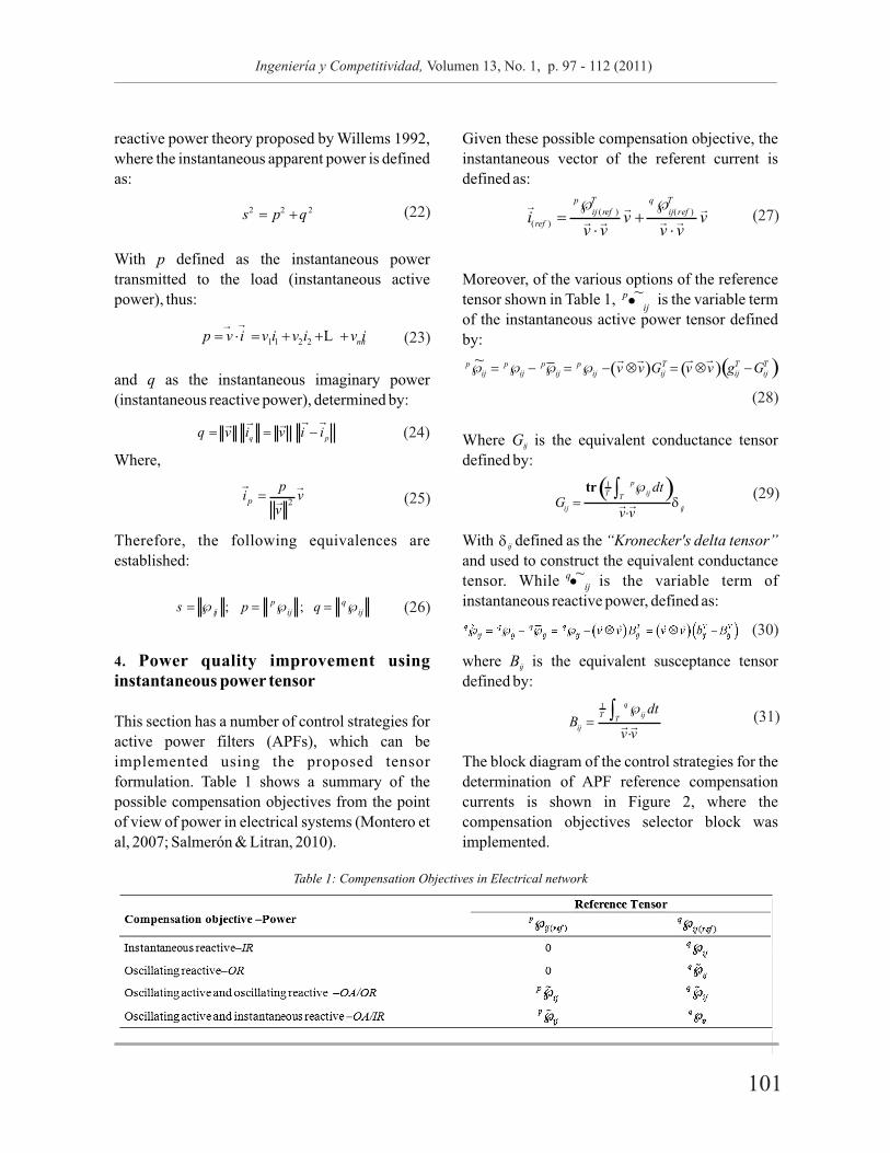
Table 1: Compensation Objectives in Electrical network
100 101
Ingeniería y Competitividad, Volumen 13, No. 1, p. 97 - 112 (2011) Ingeniería y Competitividad, Volumen 13, No. 1, p. 97 - 112 (2011)
Given these possible compensation objective, the
instantaneous vector of the referent current is
defined as:
Moreover, of the various options of the reference
tensor shown in Table 1, is the variable term
of the instantaneous active power tensor defined
by:
Where G is the equivalent conductance tensor ?
defined by:
With defined as the “Kronecker's delta tensor” ?
and used to construct the equivalent conductance
tensor. While is the variable term of
instantaneous reactive power, defined as:
where B is the equivalent susceptance tensor ?
defined by:
The block diagram of the control strategies for the
determination of APF reference compensation
currents is shown in Figure 2, where the
compensation objectives selector block was
implemented.
and in Ec. (11) is the instantaneous susceptance
tensor:
Moreover, the decomposition of the instantaneous
current vector is characterized by:
such that,
3.2 Orthogonal decomposition of the power
tensor
The decomposition of the instantaneous power
tensor is obtained by applying the tensor product
of the voltage vector on Ec. (9) , thus:
Here, the first term is the instantaneous active
power tensor:
and the second term is the instantaneous reactive
power tensor:
Consequently,
Moreover, Ec. (19) satisfies the orthogonality
concept, in other words,
Here, the tr operator corresponds to the sum of the
main diagonal elements (trace). Therefore, the
decomposition of the instantaneous power tensor
satisfies the following orthogonal relation:
The importance of the new formulation is based on
the fact that the expression for the instantaneous
reactive power in multiphase systems is known,
thanks to the decomposition of the tensor power,
given in (19). Now, thanks to know the expression
of instantaneous reactive power, there are other
compensation strategies possible for the reference
currents estimate for the control of active power
filters, regardless of the number of phases of the
power system (e.g. reactive power cancellation
and distortion power cancellation).
The expression given in (21) is equivalent to the
vector formula of the generalized instantaneous
(20)
bij
(13)
(14)
(16)
(17)
(18)
p q
ij ij ij????? (19)
pij?
~
qij?
~
(30)
Table 1: Compensation Objectives in Electrical network
100 101
Ingeniería y Competitividad, Volumen 13, No. 1, p. 97 - 112 (2011) Ingeniería y Competitividad, Volumen 13, No. 1, p. 97 - 112 (2011)

?
removed both on three-phase and six-phase side
when the active filter is connected. Therefore, the
instantaneous reactive power is fully compensated
when the active filter is connected, while the
delivered instantaneous active power equals the
instantaneous active power consumed by the load.
Regarding distortion, it's observed that the
waveform of the current signals change but the
total harmonic distortion not improvement.
The simulation results for the compensation
objective OR are shown in Figure 5 and
summarized in the fourth column of Table 2. Now,
when the active filter is connected, only the
oscillating portion of the instantaneous reactive
power is compensated thus, the source has to
continue generating a constant instantaneous
reactive power. The instantaneous active power
delivered by the source remains equal to the
instantaneous active power consumed by the load.
From the results shown in Figure 5, the instantaneous reactive current is delayed
exactly by 90º with the voltage both on three-
phase and six-phase side when the active filter is
connected.
The simulation results for the compensation
objective OA/OR are shown in Figure 6 and
summarized in the fifth column of Table 2. Here,
the oscillating active and reactive powers are
simultaneously compensated when the active
filter is connected. This time, the waveform of the
current is sinusoidal but still keeps the phase shift
obtained in the compensation objective OR. From
the results shown in Figure 6, the instantaneous active current is perfectly in phase with the voltage and instantaneous reactive current is
delayed exactly by 90º with the voltage both on
three-phase and six-phase side when the active
filter is connected.
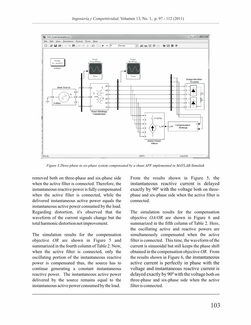
Figure 3.Three-phase to six-phase system compensated by a shunt APF implemented in MATLAB-Simulink
The different objectives of compensation have
been applied to a nonlinear six-phase system. In
this circuit, a sinusoidal and balanced three phase
voltage source, feeds a triple wound transformer
Y, Y . The secondary winding feeds a twelve pulse
controller rectifier operating with a firing angle of
45º with a source of current at the dc side assumed
as load (Figure 3). This system was chosen
because it is a practical case where six-phase
waveforms can be identified.
The circuit shown in Figure 3 has been
implemented in Matlab-Simulink. The active
power filter is modeling as an ideal current source
controlled by the referent current obtained with
the proposed tensor formulation.
Figures 4 to 7 show the simulation results for the
different compensation objectives. The voltage
and current waveforms in these figures
correspond to the first phase (phase-a in three-
phase side and phase-1 in six-phase side). In
addition, t=50ms is the time in which the active
filter is connected to the system. For all cases, the
information is organized as follows.
Three-phase system (transformer primary side):
(a) Voltage waveform, va
(b) Current waveform, ia.
(c) Active current waveform, ip_a
(d) Reactive current waveform, iq_a
p (e) Instantaneous active power, ¦ ¦? 3
q (f) Instantaneous reactive power, ¦ ¦? 3
Six-phase system (transformer secondary side):
(g) Voltage waveform, v1
(h) Current waveform, i1.
(i) Active current waveform, ip_1
(j) Reactive current waveform, iq_1
p ( ) Instantaneous active power, ¦ ¦? 6
q ( ) Instantaneous reactive power, ¦ ¦? 6
The simulation results for the compensation
objective IR are shown in Figure 4 and
summarized in the third column of Table 2. Here,
the instantaneous reactive power is completely
Figure 2: Block diagram of the control strategies for determination of APF reference current.
k
l
102 103
Ingeniería y Competitividad, Volumen 13, No. 1, p. 97 - 112 (2011) Ingeniería y Competitividad, Volumen 13, No. 1, p. 97 - 112 (2011)
?
removed both on three-phase and six-phase side
when the active filter is connected. Therefore, the
instantaneous reactive power is fully compensated
when the active filter is connected, while the
delivered instantaneous active power equals the
instantaneous active power consumed by the load.
Regarding distortion, it's observed that the
waveform of the current signals change but the
total harmonic distortion not improvement.
The simulation results for the compensation
objective OR are shown in Figure 5 and
summarized in the fourth column of Table 2. Now,
when the active filter is connected, only the
oscillating portion of the instantaneous reactive
power is compensated thus, the source has to
continue generating a constant instantaneous
reactive power. The instantaneous active power
delivered by the source remains equal to the
instantaneous active power consumed by the load.
From the results shown in Figure 5, the instantaneous reactive current is delayed
exactly by 90º with the voltage both on three-
phase and six-phase side when the active filter is
connected.
The simulation results for the compensation
objective OA/OR are shown in Figure 6 and
summarized in the fifth column of Table 2. Here,
the oscillating active and reactive powers are
simultaneously compensated when the active
filter is connected. This time, the waveform of the
current is sinusoidal but still keeps the phase shift
obtained in the compensation objective OR. From
the results shown in Figure 6, the instantaneous active current is perfectly in phase with the voltage and instantaneous reactive current is
delayed exactly by 90º with the voltage both on
three-phase and six-phase side when the active
filter is connected.
Figure 3.Three-phase to six-phase system compensated by a shunt APF implemented in MATLAB-Simulink
The different objectives of compensation have
been applied to a nonlinear six-phase system. In
this circuit, a sinusoidal and balanced three phase
voltage source, feeds a triple wound transformer
Y, Y . The secondary winding feeds a twelve pulse
controller rectifier operating with a firing angle of
45º with a source of current at the dc side assumed
as load (Figure 3). This system was chosen
because it is a practical case where six-phase
waveforms can be identified.
The circuit shown in Figure 3 has been
implemented in Matlab-Simulink. The active
power filter is modeling as an ideal current source
controlled by the referent current obtained with
the proposed tensor formulation.
Figures 4 to 7 show the simulation results for the
different compensation objectives. The voltage
and current waveforms in these figures
correspond to the first phase (phase-a in three-
phase side and phase-1 in six-phase side). In
addition, t=50ms is the time in which the active
filter is connected to the system. For all cases, the
information is organized as follows.
Three-phase system (transformer primary side):
(a) Voltage waveform, va
(b) Current waveform, ia.
(c) Active current waveform, ip_a
(d) Reactive current waveform, iq_a
p (e) Instantaneous active power, ¦ ¦? 3
q (f) Instantaneous reactive power, ¦ ¦? 3
Six-phase system (transformer secondary side):
(g) Voltage waveform, v1
(h) Current waveform, i1.
(i) Active current waveform, ip_1
(j) Reactive current waveform, iq_1
p ( ) Instantaneous active power, ¦ ¦? 6
q ( ) Instantaneous reactive power, ¦ ¦? 6
The simulation results for the compensation
objective IR are shown in Figure 4 and
summarized in the third column of Table 2. Here,
the instantaneous reactive power is completely
Figure 2: Block diagram of the control strategies for determination of APF reference current.
k
l
102 103
Ingeniería y Competitividad, Volumen 13, No. 1, p. 97 - 112 (2011) Ingeniería y Competitividad, Volumen 13, No. 1, p. 97 - 112 (2011)
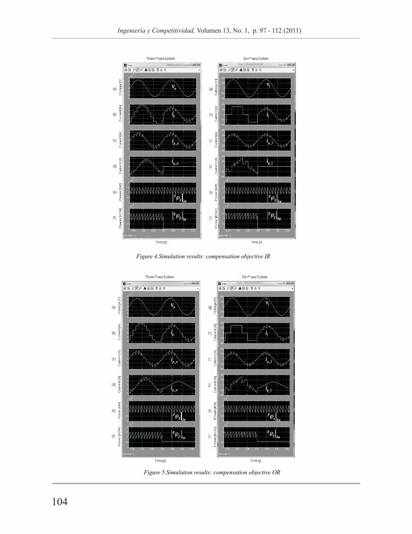
Figure 4.Simulation results: compensation objective IR
Figure 5.Simulation results: compensation objective OR
Figure 6.Simulation results: compensation objective OA/OR
Figure 7.Simulation results: compensation objective OA/IR
104 105
Ingeniería y Competitividad, Volumen 13, No. 1, p. 97 - 112 (2011) Ingeniería y Competitividad, Volumen 13, No. 1, p. 97 - 112 (2011)
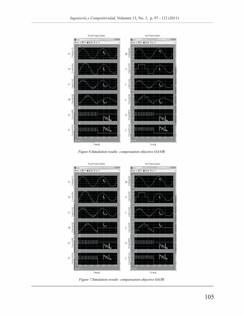
Figure 4.Simulation results: compensation objective IR
Figure 5.Simulation results: compensation objective OR
Figure 6.Simulation results: compensation objective OA/OR
Figure 7.Simulation results: compensation objective OA/IR
104 105
Ingeniería y Competitividad, Volumen 13, No. 1, p. 97 - 112 (2011) Ingeniería y Competitividad, Volumen 13, No. 1, p. 97 - 112 (2011)
The simulation results for the compensation
objective OA/IR are shown in Figure 7 and
summarized in the sixth column of Table 2. Now,
the oscillating active power and the instantaneous
reactive power are compensated when the active
filter is connected. In this compensation objective
the waveform of the current signal is also
sinusoidal. In addition the voltage and current
signals are in phase.
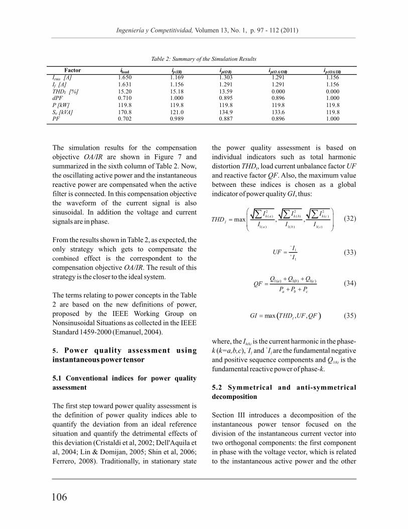
From the results shown in Table 2, as expected, the
only strategy which gets to compensate the
combined effect is the correspondent to the
compensation objective OA/IR. The result of this
strategy is the closer to the ideal system.
The terms relating to power concepts in the Table
2 are based on the new definitions of power,
proposed by the IEEE Working Group on
Nonsinusoidal Situations as collected in the IEEE
Standard 1459-2000 (Emanuel, 2004).
5. Power quality assessment using instantaneous power tensor
5.1 Conventional indices for power quality
assessment
The first step toward power quality assessment is
the definition of power quality indices able to
quantify the deviation from an ideal reference
situation and quantify the detrimental effects of
this deviation (Cristaldi et al, 2002; Dell'Aquila et
al, 2004; Lin & Domijan, 2005; Shin et al, 2006;
Ferrero, 2008). Traditionally, in stationary state
the power quality assessment is based on
individual indicators such as total harmonic
distortion THD , load current unbalance factor UF I
and reactive factor QF. Also, the maximum value
between these indices is chosen as a global
indicator of power quality GI, thus:
where, the I is the current harmonic in the phase-h(k)- + k (k=a,b,c), I and I are the fundamental negative 1 1
and positive sequence components and Q is the 1(k)
fundamental reactive power of phase-k.
5.2 Symmetrical and anti-symmetrical
decomposition
Section III introduces a decomposition of the
instantaneous power tensor focused on the
division of the instantaneous current vector into
two orthogonal components: the first component
in phase with the voltage vector, which is related
to the instantaneous active power and the other
component related to the instantaneous reactive
power. This section defines another tensor
decomposition, taking into account that any
second order tensor can be unequivocally
expressed as the sum of a symmetric tensor and an
anti-symmetric thus:
This expression can be written in compact form, as:
The operation leading from an arbitrary tensor
with components to the tensor with components
is called symmetrization, while the
operation leading to the tensor with components
is called anti-symmetrization.
The concept of symmetrization in electrical
systems corresponding to the definition of
symmetrical or ideal circuits is introduced, in the
next item, using this decomposition.
5.3 Deviation factor of power quality based on
the tensor analysis
Now, a single discriminating factor to power
quality assessment is proposed based on the
symmetrical and anti-symmetrical decomposition
of instantaneous power tensor. This factor
afterwards could be used to penalize or to
compensate the customers at the point of common
coupling (PCC), similarly as the power factor has
been used.
Establishing this factor implies to define the ideal
power system as one circuit composed of a
balanced and sinusoidal voltage source (reference
source) supplying a resistive balanced load
(reference load). Any situation producing
nonconformity with respect to these ideal
conditions supposes a quality loss. Moreover, this
ideal circuit is the unique power system that
presents a totally symmetric instantaneous power
tensor.
The evaluation of these nonconformities can be
quantified through the definition of a new power
quality index, named instantaneous deviation
indicator of power quality IDI , stated bypq
and next, the deviation factor of power quality
defined as:
ideal In the Eq (38) the term
instantaneous power tensor of the ideal power
system (tensor totally symmetric). The ideal
instantaneous power tensor is calculated as
follows:
+where v is the voltage vector with a single f fundamental positive-sequence component and
G is the equivalent conductance of the ideal (ideal)
power system.
In this paper, the power quality assessment
approach proposed based on the instantaneous
power tensor theory has been applied to a three-
phase, four-wire system. The analyzed electrical
network is similar to the one presented in Figure 8.
The electrical network was simulated in ATP-
EMTP. In addition, the DF index is in contrasted pq
against the GI index. For comparison proposes,
corresponds to the
ij
?
T
ij ij???
T
ij ij???
106 107
Ingeniería y Competitividad, Volumen 13, No. 1, p. 97 - 112 (2011) Ingeniería y Competitividad, Volumen 13, No. 1, p. 97 - 112 (2011)

The simulation results for the compensation
objective OA/IR are shown in Figure 7 and
summarized in the sixth column of Table 2. Now,
the oscillating active power and the instantaneous
reactive power are compensated when the active
filter is connected. In this compensation objective
the waveform of the current signal is also
sinusoidal. In addition the voltage and current
signals are in phase.
From the results shown in Table 2, as expected, the
only strategy which gets to compensate the
combined effect is the correspondent to the
compensation objective OA/IR. The result of this
strategy is the closer to the ideal system.
The terms relating to power concepts in the Table
2 are based on the new definitions of power,
proposed by the IEEE Working Group on
Nonsinusoidal Situations as collected in the IEEE
Standard 1459-2000 (Emanuel, 2004).
5. Power quality assessment using instantaneous power tensor
5.1 Conventional indices for power quality
assessment
The first step toward power quality assessment is
the definition of power quality indices able to
quantify the deviation from an ideal reference
situation and quantify the detrimental effects of
this deviation (Cristaldi et al, 2002; Dell'Aquila et
al, 2004; Lin & Domijan, 2005; Shin et al, 2006;
Ferrero, 2008). Traditionally, in stationary state
the power quality assessment is based on
individual indicators such as total harmonic
distortion THD , load current unbalance factor UF I
and reactive factor QF. Also, the maximum value
between these indices is chosen as a global
indicator of power quality GI, thus:
where, the I is the current harmonic in the phase-h(k)- + k (k=a,b,c), I and I are the fundamental negative 1 1
and positive sequence components and Q is the 1(k)
fundamental reactive power of phase-k.
5.2 Symmetrical and anti-symmetrical
decomposition
Section III introduces a decomposition of the
instantaneous power tensor focused on the
division of the instantaneous current vector into
two orthogonal components: the first component
in phase with the voltage vector, which is related
to the instantaneous active power and the other
component related to the instantaneous reactive
power. This section defines another tensor
decomposition, taking into account that any
second order tensor can be unequivocally
expressed as the sum of a symmetric tensor and an
anti-symmetric thus:
This expression can be written in compact form, as:
The operation leading from an arbitrary tensor
with components to the tensor with components
is called symmetrization, while the
operation leading to the tensor with components
is called anti-symmetrization.
The concept of symmetrization in electrical
systems corresponding to the definition of
symmetrical or ideal circuits is introduced, in the
next item, using this decomposition.
5.3 Deviation factor of power quality based on
the tensor analysis
Now, a single discriminating factor to power
quality assessment is proposed based on the
symmetrical and anti-symmetrical decomposition
of instantaneous power tensor. This factor
afterwards could be used to penalize or to
compensate the customers at the point of common
coupling (PCC), similarly as the power factor has
been used.
Establishing this factor implies to define the ideal
power system as one circuit composed of a
balanced and sinusoidal voltage source (reference
source) supplying a resistive balanced load
(reference load). Any situation producing
nonconformity with respect to these ideal
conditions supposes a quality loss. Moreover, this
ideal circuit is the unique power system that
presents a totally symmetric instantaneous power
tensor.
The evaluation of these nonconformities can be
quantified through the definition of a new power
quality index, named instantaneous deviation
indicator of power quality IDI , stated bypq
and next, the deviation factor of power quality
defined as:
ideal In the Eq (38) the term
instantaneous power tensor of the ideal power
system (tensor totally symmetric). The ideal
instantaneous power tensor is calculated as
follows:
+where v is the voltage vector with a single f fundamental positive-sequence component and
G is the equivalent conductance of the ideal (ideal)
power system.
In this paper, the power quality assessment
approach proposed based on the instantaneous
power tensor theory has been applied to a three-
phase, four-wire system. The analyzed electrical
network is similar to the one presented in Figure 8.
The electrical network was simulated in ATP-
EMTP. In addition, the DF index is in contrasted pq
against the GI index. For comparison proposes,
corresponds to the
ij
?
T
ij ij???
T
ij ij???
106 107
Ingeniería y Competitividad, Volumen 13, No. 1, p. 97 - 112 (2011) Ingeniería y Competitividad, Volumen 13, No. 1, p. 97 - 112 (2011)

several simulations done using both ideal and
distorted voltage under different load current
conditions. The details of each load connected at
the PCC are shown in Figure 9.
The RMS values of the voltage and the values of
the parameters of the power system under study
are shown in Table 3. The system impedance is
assumed to be of a resistance of 0.892 m in
series with an inductance of 0.016 mH.
Table 4 shows a summary of the simulated cases.
In the Table 4, the script “on” refers to the
connection of the source or disturbing load in the
PCC, while the script “off” refers to the non-
connection. Figure 10 shows the voltage and
current waveforms measurement in the case H.
Table 5 shows the values of the individual
conventional indicators used in the evaluation of
the power quality in each of the simulated cases.
Figure 8.The studied example implemented in ATP-EMTP
Figure 9.Three-phase loads connected in the studied example: (a) ideal load, (b) disturbing load #1(unbalanced),
(c) disturbing load #2 (inductive) and (d) disturbing load #3 (nonlinear).
?
Figure 10.Voltage and current waveform for the case H: (a) PCC voltage, (b) PCC current, (c) ideal load current,
(d) unbalanced load current (e) inductive load current and (f) nonlinear load current.
108 109
Ingeniería y Competitividad, Volumen 13, No. 1, p. 97 - 112 (2011) Ingeniería y Competitividad, Volumen 13, No. 1, p. 97 - 112 (2011)
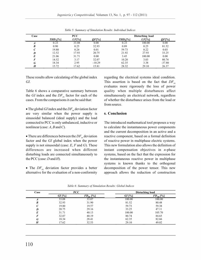
Case PCC Disturbing load GI [%] FDpq
[%] GI [%] FD pq [%]
A 33.08 33.07 100.00 100.00B 32.93 31.90 81.52 80.48
C 19.80 19.57 59.73 59.38
D 20.75 29.16 33.25 47.11
E 31.71 40.13 100.00 105.70F 32.07 40.19 80.74 84.65
G 18.34 28.41 62.35 82.66 H 17.62 32.53 29.10 49.02
Table 6: Summary of Simulation Results: Global Indices
These results allow calculating of the global index
GI.
Table 6 shows a comparative summary between
the GI index and the DF factor for each of the pq
cases. From the comparisons it can be said that:
? The global GI index and the DF deviation factor pq
are very similar when the power supply is
sinusoidal balanced (ideal supply) and the load
connected to PCC is only unbalanced, inductive or
nonlinear (case: A, B and C).
? There are differences between the DF deviation pq
factor and the GI global index when the power
supply is not sinusoidal (case: E, F and G). These
differences are increased when different
disturbing loads are connected simultaneously to
the PCC (case: D and H).
? The DF deviation factor provides a better pq
alternative for the evaluation of a non-conformity
regarding the electrical systems ideal condition.
This assertion is based on the fact that DF pq
evaluates more rigorously the loss of power
quality when multiple disturbances affect
simultaneously an electrical network, regardless
of whether the disturbance arises from the load or
from source.
6. Conclusion
The introduced mathematical tool proposes a way
to calculate the instantaneous power components
and the current decomposition in an active and a
reactive component, based on a formal definition
of reactive power in multiphase electric systems.
This new formulation also allows the definition of
instant compensation objectives in n-phase
systems, based on the fact that the expression for
the instantaneous reactive power in multiphase
systems is known thanks to the orthogonal
decomposition of the power tensor. This new
approach allows the reduction of construction
costs of the APFs, given that now APFs can be
designed at low voltages in the case of rectifiers of
twelve, eighteen, twenty four and more pulses. A
single DF index has been proposed as the basis of pq
the power quality assessment based on the
instantaneous power tensor theory. The deviation
indicator of power quality proved to be successful,
as found by comparisons made between the ideal
power system introduced and many other typical
loads selected from a variety of test cases. So, the
New Theoretical Approach does not present any
problem to be used as the base of an active power
filter control algorithm or a global index for power
quality assessment, with any voltage conditions in
the point of common coupling (PCC). The results
have been corroborated by the correspondent
simulations in the Matlab-Simulink and ATP-
EMTP environments.
7. List of Symbols
8. References
Akagi, H., Kanazawa, Y., & Nabae, A. (1984). Instantaneous reactive power compensators comprising switching devices without energy storage components. IEEE Transaction on Industry Applications 20(3), 625-631.
Cristaldi L., Ferrero, A., & Salicone, S. (2002). A Distributed System for Electric Power Quality Measurement . IEEE Transac t ions on Instrumentation and Measurement 51(4), 776-778.
C z a r n e c k i , L . S . ( 2 0 0 4 ) . O n S o m e Misinterpretations of the Instantaneous Reactive Power p-q Theory. IEEE Transaction on Power Electronics 19(3), 828-836.
Dai, X., Liu, G., & Gretsch, R. (2004). Generalized Theory of Instantaneous Reactive Quantity for Multiphase Power System. IEEE Transaction on Power Delivery 19(3), 965-972.
Dell'Aquila, A., Marinelli, M., Monopoli, V. G., & Zanchetta, P. (2004). New Power-Quality Assessment Criteria for Supply Under Unbalanced and Nonsinusoidal Conditions. IEEE Transaction on Power Delivery 19(3), 1284-1290.
Depenbrock, M., Staudt, V., & Wreder, H. (2003). A theoretical investigation of original and modified instantaneous power theory applied to four-wire systems. IEEE Transaction on Industry Applications 39(4), 1160-1167.
Depenbrock, M. (1993). The FBD-Method, A Generally Applicable tool for Analyzing Power Relations. IEEE Transactions on Power Systems 8(2), 381-387.
Emanuel, A.E. (2004). Summary of IEEE Standard 1459: Definitions for the Measurement of Electric Power Quantities Under Sinusoidal, Nonsinusoidal, Balanced, or Unbalanced Conditions. IEEE Transaction on Industry Applications 40(3), 869-876.
Ferrero, A. (2008). Measuring Electric Power Qua l i ty : P rob lems and Per spec t ives . Measurement 41(2), 121-129.
Itskov, M. (2007). Tensor Algebra and Tensor Analysis for Engineers: with Applications to Continuum Mechanics, Springer, Berlin.
Leon, F. de, & Cohen, J. (2008). Discussion of Instantaneous Reactive Power p-q Theory and Power Properties of Three-Phase Systems. IEEE Transaction on Power Delivery 23(3), 1693-1694.
110 111
Ingeniería y Competitividad, Volumen 13, No. 1, p. 97 - 112 (2011) Ingeniería y Competitividad, Volumen 13, No. 1, p. 97 - 112 (2011)

Lin, T., & Domijan, A. (2005). On power quality indices and real time measurement. IEEE Transaction on Power Delivery 20(4), 25522562.
Montero, M.I.M., Cadaval, E.R., & Gonzalez, F.B. (2007). Comparison of Control Strategies for Shunt Active Power Filters in Three-Phase Four-Wire Systems. IEEE Transaction on Power Electronics 22(1), 229236.
Morsi, W.G., & El-Hawary M.E. (2007). Defining power components in nonsinusoidal unbalanced polyphase systems: the issues. IEEE Transaction on Power Delivery 22(4), 24282438.
Salmerón, P., & Herrera, R.S. (2009). Instantaneous Reactive Power Theory A General Approach to Poly-Phase Systems. Electric Power Systems Research. 79, 1263-1270.
Salmerón, P., & Litran, S.P. (2010). Improvement of the Electric Power Quality Using Series Active and Shunt Passive Filters. IEEE Transaction on Power Delivery 25(2), 1058-1067.
Shin, Y.J., Powers, E.J., Grady, M. & Arapostathis, A. (2006). Power Quality Indices for Transient Disturbances. IEEE Transaction on Power Delivery 21(1), 253-261.
Ustariz, A.J. Cano, E.A. and Tacca, H.E. (2010). Ins tantaneous Power Tensor Theory: Improvement and Assessment of the Electric Power Quality. In Proceedings of the 14th International Conference on Harmonics and Quality of Power (ICHQP), Bergamo, Italy, pp. 1-
Willems, J.L. (1992). A New Interpretation of the Akag i -Nabae Power Componen t s fo r Nonsinusoidal Three-phase Situations. IEEE Transact ions on Ins trumentat ion and Measurement 41(4), 523-527.
112
Ingeniería y Competitividad, Volumen 13, No. 1, p. 97 - 112 (2011)