DAILY - up.picr.de · Esquema alámbrico 23 Cableo para embrague electromagnético del compresor 25...
28
COD. 01025015/2 COD. 01025021/1 COD. 01025026/1 ISTRUZIONI DI MONTAGGIO CONDIZIONATORE CLIMATIZATION SYSTEM ASSEMBLY INSTRUCTIONS INSTRUCTIONS POUR LE MONTAGE DU CLIMATISEUR MONTAGEANLEITUNG FÜR KLIMAANLAGE INSTRUCCIONES PARA EL MONTAJE DEL DISPOSITIVO DE CLIMATIZACION IVECO DAILY
Transcript of DAILY - up.picr.de · Esquema alámbrico 23 Cableo para embrague electromagnético del compresor 25...

COD. 01025015/2 COD. 01025021/1 COD. 01025026/1
ISTRUZIONI DI MONTAGGIO CONDIZIONATORE CLIMATIZATION SYSTEM ASSEMBLY INSTRUCTIONS
INSTRUCTIONS POUR LE MONTAGE DU CLIMATISEUR MONTAGEANLEITUNG FÜR KLIMAANLAGE
INSTRUCCIONES PARA EL MONTAJE DEL DISPOSITIVO DE CLIMATIZACION
IVECO
DAILY
IVECO DAILY
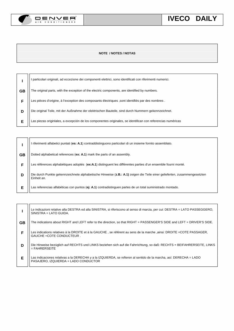
NOTE / NOTES / NOTAS
I
I particolari originali, ad eccezione dei componenti elettrici, sono identificati con riferimenti numerici.
GB The original parts, with the exception of the electric components, are identified by numbers.
F Les pièces d’origine, à l’exception des composants électriques ,sont identifiés par des nombres .
D Die original Teile, mit der Außnahme der elektrischen Bauteile, sind durch Nummern gekennzeichnet.
E Las piezas originlales, a excepción de los componentes originales, se identifican con referencias numéricas
I
I riferimenti alfabetici puntati (es: A.1) contraddistinguono particolari di un insieme fornito assemblato.
GB Dotted alphabetical references (ex: A.1) mark the parts of an assembly.
F Les références alphabétiques adoptés (ex:A.1) distinguent les différentes parties d’un ensemble fourni monté.
D Die durch Punkte gekennzeichnete alphabetische Hinweise (z.B.: A.1) zeigen die Teile einer gelieferten, zusammengesetzten
Einheit an.
E Las referencias alfabéticas con puntos (ej: A.1) contradistinguen partes de un total suministrado montado.
I
Le indicazioni relative alla DESTRA ed alla SINISTRA, si riferiscono al senso di marcia, per cui: DESTRA = LATO PASSEGGERO, SINISTRA = LATO GUIDA.
GB The indications about RIGHT and LEFT refer to the direction, so that RIGHT = PASSENGER’S SIDE and LEFT = DRIVER’S SIDE.
F Les indications relatives à la DROITE et à la GAUCHE , se référent au sens de la marche ,ainsi: DROITE =COTE PASSAGER,
GAUCHE =COTE CONDUCTEUR .
D Die Hinweise bezüglich auf RECHTS und LINKS beziehen sich auf die Fahrrichtung, so daß: RECHTS = BEIFAHRERSEITE, LINKS = FAHRERSEITE
E Las indicaciones relativas a la DERECHA y a la IZQUIERDA, se refieren al sentido de la marcha, así: DERECHA = LADO
PASAJERO, IZQUIERDA = LADO CONDUCTOR

IVECO DAILY
SOMMARIO PAGINA
Componenti forniti con il gruppo evaporatore 1
Componenti forniti con il set di montaggio 10
Circuito frigorigeno 15/20
Quantità di refrigerante 22
Schema impianto elettrico 23
Cablaggio per frizione elettromagnetica del compressore 25
CONTENTS PAGE
Composants supplied with the evaporator set 1
Components supplied with the assembly kit 10
Cooling system 15/20
Amount of coolant 22
Electrical wiring diagram 23
Wiring for compressor electro-magnetic clutch 25
SOMMAIRE PAGE
Composants fournis avec le groupe évaporateur 1
Composants fournis avec le groupe de montage 10
Circuit frigorigène 15/20
Quantité de réfrigérant 22
Schéma installation électrique 23
Câblage pour embrayage électromagnétique du compresseur 25
INHALT SEITE
Mit der Verdampfergruppe gelieferte Bauteile, Montageanleitung 1
Mit dem Montageset gelieferte Bauteile 10
Kühlkreislauf 15/20
Kühlmittelmenge 22
Elektrischer Schaltplan 23
Verkabelung für die elektromagnetische Kupplung des Kompressors 25
PAGINA
Componentes suministrados con el grupo evaporador 1
Componentes suministrados con el set de montaje 10
Circuito de refrigeración 15/20
Cantidad de refrigerador 22
Esquema alámbrico 23
Cableo para embrague electromagnético del compresor 25
GB
F
D
E
I

IVECO DAILY
1
COMPONENTI FORNITI CON IL GRUPPO EVAPORATORE COD. 20201112.2
COMPONENTS SUPPLIED WITH THE EVAPORATOR ASSEMBLY CODE 20201112.2 COMPOSANTS FOURNIS AVEC LE GROUPE EVAPORATEUR COD. 20201112.2 MIT DER EVAPORATOR EINHEIT KODE 20201112.2 GELIEFERTE BESTANDTEILE COMPONENTES SUMINISTRADOS CON EL GRUPO VAPORIZADOR COD. 20201112.2
CODICE CODE CODE CODIGO
Q.TA RIF. DESCRIZIONE DESCRIPTION NOMENCLATURE BEZEICHNUNG DENOMINACION
20205165.1 1 A Blocco evaporatore / Evaporator block / Bloc évaporateur / Verdunster Block / Bloque vaporizador
20210030 1 A.1 Batteria evaporatrice / Evaporator coil / Batterie évaporateur / Verdunster Batterie / Baterìa vaporizadora
20299001 4 A.2 Bocchetta aria / Air opening / Bouche d’air / Luftöffnung / Entrada de aire externo
2021589041 1 A.3 Valvola di espansione / Expansion valve Soupape d’expansion / Expansionsventil / Vàlvula de expansiòn
20220001 1 A.4 Elettroventola / Electric fan / Electroventilateur / Elektroventilator / Ventilador elèctrico
B.1
A.5
A.6
A.4
A A.2
B
L
H M
I
G
E
F
D
C

IVECO DAILY
2
2024055006 1 A.5 Termostato / Thermostat / Thermostat / Thermostat / Termostato
2025556577 1 A.6 Selettore velocità ventilazione / Ventilation speed selector / Sélecteur vitesse ventilateur /
Veintilationsgeschwindigkeitsschalter / Selector de velocidad de ventilaciòn
20255039 2 A.7 Pomello / Knob / Pommeau / Schalter / Pomo
20260068 1 A.8 Cablaggio evaporatore / Evaporator wiring / Câblage évaporateur / Verduynsterverkabelung / Cableado del evaporador
20290436 1 B Condotto aria terminale / Terminal air duct / Conduit air terminal / Endluftlutte / Ducto terminal de aire
20299001 1 B.1 Bocchetta aria / Air opening/ Bouche d’air / Luftöffnung / Abertura de aire
20265228 1 C Staffa fissaggio evaporatore / Evaporator fixing bracket / Bride de fixation de l’évaporateur / Verdunsterbefestigungsbügel / Abrazadera para fijaciòn del vaporizador
50543863 2 D Distanziale Ø5xØ8xH.18 / Ø5xØ8xH.18 spacer / Entretoise Ø5xØ8xH.18 / Abstandstück Ø5xØ8xH.18 / Espaciador Ø5xØ8xH.18
2027003302 cm.10 E Tubo scarico acqua di condensa Ø12xØ17 / Ø12xØ17 condensate water exhaust pipe / Tube d’évacuation eau de condensation Ø12xØ17 / Kondenswasserauslassrohr Ø12xØ17 / Tubo de descarga del agua de condensaciòn Ø12xØ17
2027003302 cm.50 F Tubo scarico acqua di condensa Ø12xØ17 / Ø12xØ17 condensate water exhaust pipe / Tube d’évacuation eau de condensation Ø12xØ17 / Kondenswasserauslassrohr Ø12xØ17 / Tubo de descarga del agua de condensaciòn Ø12xØ17
2027003302 cm. 100
G Tubo scarico acqua di condensa Ø12xØ17 / Ø12xØ17 condensate water exhaust pipe / Tube d’évacuation eau de condensation Ø12xØ17 / Kondenswasserauslassrohr Ø12xØ17 / Tubo de descarga del agua de condensaciòn Ø12xØ17
6065082919 1 H Raccordo per tubi scarico acqua di condensa / Fitting for condensate water exhaust pipes / Raccord pour tube d’évacuation eau de condensation / Verbindungsstück für Kondenswasserauslassrhröhre / Empalme para tubos de descarga del agua de condensaciòn
6066609112 2 I Gommino passatubo diam.int. 18 / Int. diam.18 pipe rubber block / Caoutchouc Ø18 interne pour passage de tube / Rohrdurchlassgummi Innendurchm. 18 / Goma para interior del tubo diam. interior 18
20295052 1 L Guarnizione / Seal / Garniture / Dichtung / Guarniciòn
20285036 - M Set viterie / Set of screws / Visserie pour évaporateur / Schraubensatz für Verdampfer / Tornillos del evaporator
70722850 2 AA Vite T.C. T.cr M.6x25 / T.C. T.cr M.6x25 screw / Vis T.C. T.cr M.6x25 / T.C. T.cr M.6x25 Schraube / tornillo T.C.
T.cr M.6x25
70720048 2 BB Vite T.E. M.5x30 / T.E. M.5x30 screw / Vis tête hexagonale M.5x30 / T.E. M.5x30 Schraube / Tornillo T.E. M5x30
70724090 5 CC Vite autofilettante T.cr. 3,9x12,7 / T.cr. 3,9x12,7 self-threading screw / vis autotaraudeuses T.cr. 3,9x12,7 / T.cr. 3,9x12,7 selbstschneidende Schraube / Tornillo de autoenroscado .cr. 3.9x12.7
70726059 2 DD Grano M.6x20 / M.6x20 dowel / Vis sans tête M.6x20 / Gewinde M.6x20 / Espiga de ensamble M.6x20
70728008 4 EE Rondella piana Ø4,5xØ9xH.0,8 / Ø4,5xØ9xH.0,8 plain washer / Rondelle platte Ø4,5xØ9xH.0,8 / Flache Unterlegscheibe Ø4,5xØ9xH.0,8 / Arandela plana Ø4,5xØ9xH.0,8
70728014 6 FF Rondella piana Ø5,5xØ10xH.1,5 / Ø5,5xØ10xH.1,5 plain washer / Rondelle platte Ø5,5xØ10xH.1,5 / Flache Unterlegscheibe Ø5,5xØ10xH.1,5 / Arandela plana Ø5,5xØ10xH.1,5
70728020 2 GG Rondella piana Ø6xØ18xH.1,5 / Ø6xØ18xH.1,5 plain washer / Rondelle platte Ø6xØ18xH.1,5 / Flache Unterlegscheibe Ø6xØ18xH.1,5 / Arandela plana Ø6xØ18xH.1,5
70728246 2 HH Rondella ondulata Ø6 / Ø6 waved washer / Rondelle ondulée Ø6 / Gewellte Unterlegscheibe Ø6 / Arandela ondulada Ø6
70728539 4 II Dado stop M.5 / M.5 self-locking nut / Ecrou stop M.5 / Selbstsichernde Mutter M.5 / Tuerca autoblocante M.5

IVECO DAILY
3
ISTRUZIONI DI MONTAGGIO EVAPORATORE EVAPORATOR ASSEMBLY INSTRUCTIONS
INSTRUCTIONS DE MONTAGE EVAPORATEUR MONTAGEINSTRUKTIONEN FÜR VERDAMPFER
ISTRUCCIONES PARA EL MONTAJE UNIDAD EVAPORADORA
I Scollegare la batteria.
GB Disconnect the battery.
F Débrancher la batterie.
D Die Batterie abklemmen.
E Desconectar la baterìa
I Smontare il vano predisposizione autoradio e la mostrina con i leveraggi per la temperatura, immissione e distribuzione aria, completa di
selettore velocità ventilazione.
GB Disassemble the car radio compartment and the clamp with the leverages for temperature, air inlet and distribution, complete with the ventilation speed selector.
F Démonter le compartiment prévu pour l’autoradio et le tableau avec les commandes de température, envoi et distribution de l’air, ensemble
avec le sélecteur de vitesse de ventilation.
D Das für das Autoradio vorgesehene Fach und die Bedeckung mit den Schaltern der Lufttemperatur, des Lufteinlaßes und der Luftversorgung, den Ventilatorgeschwindigkeitsschalter inbegriffen, abmontieren.
E Desmontar el compartimiento de la radio del auto y el sujetador con los varillajes para la temperatura, admisiòn y distribuciòn de aire,
completa de selector de velocidad de ventilacòn. I Inserire i 2 grani M. 6 forniti rif.”DD” nelle boccole superiori dell’evaporatore (vedi fig. 1).
GB Insert the 2 M. 6 dowels supplied ref.“DD” in the evaporator upper bushings (see drawing n. 1).
F Placer les 2 vis sans tête M. 6 fournies ref.”DD” dans les bagues supérieures de l’évaporateur (voir fig. 1).
D Die 2 gelieferten Gewinde M. 6 bez.”DD” in den oberen Buchsen des Verdunsters einfügen (siehe Bild 1).
E Insertar las 2 espigas de ensamble M. 6 suministradas ref.“DD” en los casquillos superiores del vaporizador (ver fig. 1).
I Posizionare il blocco evaporatore sotto il cassetto portaoggetti del cruscotto in modo che i grani M. 6 rif.”DD” segnino i punti in cui eseguire
i 2 fori diam. 7 per il fissaggio superiore dell’evaporatore.
GB Position the evaporator block under the dashboard glove compartment, so that the M. 6 dowels ref.“DD” mark the points where the 2 diam. 7 holes shall be made for the evaporator upper clamping.
F Positionner le bloc évaporateur sous la boîte à gants de manière à ce que les vis sans tête M. 6 ref.”DD” indiquent les points où percer les
2 trous diam. 7 pour la fixation supérieure de l’évaporateur.
D Den Verdunster Block unter dem Konsolefach positionieren, so daß die Gewinde M. 6 bez.”DD” die Punkte, wo man 2 Löcher von Durchm. 7 zur oberen Befestigung des Verdunsters bohren muß, anzeigen.
E Posicionar el bloque vaporizador debajo del cajòn portaobjetos del tablero de manera que las espigas de ensamble M. 6 ref.“DD” indiquen
los puntos en los que se debe hacer los agujeros diam. 7 para la fijaciòn superior del vaporizador. I Montare la staffa rif.”C” sul blocco evaporatore, utilizzando per il suo fissaggio 2 rondelle piane diam. 5 rif.”FF” con 2 dadi M. 5 stop
rif.”II” (vedi fig. 1).
GB Assemble the bracket ref.“C” on the evaporator block, and clamp it by using 2 diam. 5 plain washers ref.“FF” with 2 M. 5 self-locking nuts ref.“II” (see drawing n. 1).
F Monter la bride rif.”C” sur le bloc évaporateur, en utilisant pour la fixation 2 rondelles plates diam. 5 ref.”FF” et 2 écrous M. 5 stop ref.”II”
(voir fig. 1).
D Den Bügel bez.”C” an den Verdunster Block montieren, dazu 2 flache Unterlegscheiben Durchm. 5 bez.”FF” mit 2 selbstsichernden Muttern bez.”II” benutzen (siehe Bild 1).
E Moontar la abrazadera ref.“C” en el bloque evaporador, utilizando para su fijaciòn 2 rondelas planas diam. 5 ref.“FF” con dos tuercas M.5
autoblocantes ref.“II” (ver fig. 1).
1
2
3
4
5

IVECO DAILY
4
FIG.1

IVECO DAILY
5
I Operando dal vano motore, eseguire 1 foro diam. 25 nel punto indicato in fig. 2 per il passaggio cablaggio elettrico.
GB From the engine compartment, make a diam. 25 hole to the
point shown on drawing n. 2, for the passage of the wiring harness.
F Du côté moteur, percer 1 trou diam. 25 au point indiqué sur la
fig. 2 pour le passage du câblage électrique.
D Von dem Motorraum aus, 1 Loch Durchm. 25 in dem Punkt,
der in dem Bild 2 gezeigt ist, zum Durchgang der elektrischen Verkabelung bohren.
E Operando del compartimiento del motor hacer un agujero
diam. 25 en el punto indicado en la fig. 2 para el paso del cableado elèctrico.
I Eseguire n°2 fori diam. 38 sulla parete parafiamma, seguendo le quote riportate in fig. 3 per il passaggio tubi refrigerante ed 1 foro diam. 20 per la fuoriuscita del tubo scarico acqua di condensa.
GB Make 2 diam. 38 holes on the fireproof wall, by following the quotas shown on the drawing n. 3 for the passage of the coolant pipes, and 1 diam. 20 hole for the condensate water pipe discharge.
F Percer 2 trous diam. 38 sur la paroi anti-flammes, en suivant les mesures indiquées sur la fig. 3 pour le passage des tubes du réfrigérant et un diam. 20 pour la sortie du tube d’évacuation de l’eau de condensation.
D 2 Löcher Durchm. 38 in der Flammsperrewand bohren, sich dazu an den Maßangaben in dem Bild 3 zum Durchgang der Kühlmittelröhre halten, und 1 Loch zum Ausgang des Kondenswasserauslaßrohres bis zum Durchm. 20 erweitern.
E Hacer 2 agujeros diam. 38 en la pared parafuegos siguiendo las cuotas obtenidas en la fig. 3 para el paso de los tubos refrigerantes y 1 agujero diam. 20 para la salida al exterior del tubo de descarga del agua de condensaciò.
I Fissare provvisoriamente l’evaporatore al cassetto portaoggetti (mediante 2 viti T.C.T.cr. M.6x25 rif.”AA” con rondelle piane Ø6xØ18
rif.”GG” e rondelle ondulate Ø6 rif.”HH”) e segnare sulla parete divisoria vano abitacolo/vano motore i 2 punti rif.”101” in cui fissare la staffa di supporto evaporatore rif.”C” (vedi fig. 1 e 4), quindi smontarlo.
GB Temporarily fix the evaporator to the glove compartment (by means of 2 T.C.T.cr. M.6x25 screws ref.”AA” with Ø6xØ18 plain washers
ref.“GG” and Ø6 waved washers ref. “HH”) and mark the 2 points ref.“101” on the passenger’s compartment/ engine compartment wall where the evaporator holding bracket ref.“C” shall be clamped (see drawings n. 1 and 4), then disassemble it.
F Fixer provisoirement l’évaporateur à la boîte à gants (grâce aux 2 vis T.C.T.cr. M.6x25 ref.”AA” avec les rondelles plates Ø6xØ18 ref.”GG”
et les rondelles ondulées Ø6 ref.”HH”) et indiquer, sur la paroi de division entre habitacle et moteur, les 2 points ref.”101” où fixer la bride de support de l’évaporateur ref.”C” (voir fig. 1 et 4), puis démonter l’évaporateur.
D Den Verdunster vorläufig an den Konsolefach befestigen (dazu 2 Schrauben T.C.T.cr. M.6x25 bez.”AA” mit flachen Unterlegscheiben
Ø6xØ18 bez.”GG” und gewellten Unterlegscheiben Ø6 bez.”HH” benutzen) und auf der Fahrerraum / Motorraumtrennungswand die 2 Punkte bez.”101”, wo der Verdunsterstützbügel bez.”C” befestigt werden muß (siehe Bild 1 und 4), kennzeichnen, dann den Verdunster wieder abmontieren.
E Fijar provisionalmente el evaporador al cajòn portaobjetos (mediante 2 tornillos T.C.T.cr M.6x25 ref.”AA” con arandelas planas Ø6xØ18
ref.“GG” y arandelas onduladas Ø6 ref.“HH”) y marcar en la pared divisoria entre el compartimiento habitàculo y el compartimiento del motore los 2 puntos ref.“101” en los cuales fijar el colgador de soporte del vaporizador ref.“C” (ver fig 1 y 4), posteriormente desmontarlo.
6
7
8
FIG.2
FIG.3
Ø 25
Ø38 Ø38
Ø20

IVECO DAILY
6
I Eseguire nei punti rif.”101” 2 fori diam. 5 sulla parete di lamiera posteriore e 2 fori diam. 9 corrispondenti, sul pannello di rivestimento anteriore (vedi fig. 4).
GB Make 2 diam. 5 holes to the points ref.“101”, on the rear
sheet wall, and 2 corresponding diam. 9 holes on the front cover panel (see drawing n. 4).
F Percer, aux points ref.”101”, 2 trous d’un diam. 5 sur la paroi
postérieure en tôle et 2 trous d’un diam. 9 en correspondance sur le panneau du revêtement antérieur (voir fig. 4).
D 2 Löcher Durchm. 5 in den Punkten bez.”101” in der hinteren
Blechwand und 2 entsprechende Löcher Durchm. 9 in der vorderen Bedeckungstafel bohren (siehe Bild 4).
E Efectuar en los puntos ref.”101” 2 agujeros diam. 5 en la
pared de plancha posterior y 2 agujeros diam. 9correspondientes en el panel de revestimiento anterior (ver fig 4).
I Inserire nei fori diam. 38 precedentemente eseguiti (vedi nota n°7) i gommini forniti con il set di montaggio (rif.”Q” pag. 24); introdurre
dall’esterno i tubi refrigerante G6 e G10 e collegarli all’evaporatore utilizzando per il loro fissaggio la piastrina presente sul tubo G10 con vite M.6x14 + rondella ondulata diam. 6 (fornite con il set di montaggio).
GB Insert the rubber blocks supplied with the mounting set (ref. “Q” on page 24) in the diam. 38 holes which were previously made (see note
n. 7), then insert the G6 and G10 hoses from the outside and connect them with the evaporator. Fix them by using the clamp which is on the G10 hose, with M. 6x14 screw and diam. 6 waved washer (supplied with the mounting set).
F Mettre les joints en caoutchouc fournis avec le set de montage (ref.”Q” pag. 24) dans les trous d’un diam. 38 précédemment percés (voir
note n°7); introduire, depuis l’extérieur, les tubes de réfrigérant G6 et G10 et les raccorder à l’évaporateur en utilisant, pour la fixation, la plaquette présente sur le tube G10 avec les vis M.6x14 plus les rondelles ondulées diam. 6 (fournies avec le set de montage).
D Die mit dem Montageset (bez.”Q” Seite 24) gelieferten Gummidichtungen in den vorher gebohrten Löchern Durchm. 38 (siehe
Anmerkung n°7) einfügen; die Kühlmittelröhre G6 und G10 von der Außenseite einfügen und sie an den Verdunster anschliessen, dazu das Plättchen, das sich auf dem Rohr G10 befindet, mit M.6x14 Schraube und gewellter Unterlegscheibe Durchm. 6 benutzen (mit dem Montageset geliefert).
E Meter en los agujeros diam. 38 hechos previamente (ver nota n°7) las gomas que vienen con el set de montaje (ref. “Q” pag. 24)
introducir del externo los tubos refrigerantes G6 y G10 y colegarlos al evaporador utilizando para su fijaciòn la plaqueta presente en el tubo G10 con tornillos M.6x14 + una arandela ondulada diam. 6 (que vienen con el set de montaje).
I Inserire nel foro diam. 20 precedentemente eseguito (vedi nota n°7) 2 gommini rif.”I” (1 sulla parete esterna ed 1 sulla parete interna) ed
introdurre il tubo scarico acqua di condensa rif.”G”, facendolo fuoriuscire nel vano motore (vedi fig. 4).
GB Insert the 2 rubber blocks ref.“I” in the hole diam. 20 previously make (see note n. 7) (1 in the external wall and 1 in the internal wall), then insert the condensate water exhaust pipe ref. “G” and let it come out of the engine compartment (see drawing n. 4).
F Mettre les 2 joints en caoutchouc ref.”I” à l’intérieur du trou diam. 20 précédemment percé (voir note n°7) (1 sur la paroi externe et sur la face interne) et faire passer le tube d’évacuation de l’eau de condensation ref.”G”, en le faisant sortir à l’intérieur du compartiment moteur (voir fig. 4).
D 2 Gummidichtungen bez.”I” in das vohrer bis zum Durchm. 20 Loch gebohrt (siehe Anmerkung n°7) einfügen ( 1 auf der Außenseite und 1 auf der Innenseite), dann das Kondenswasserauslaßrohr rif.”G” einfügen und ihn in den Motorraum herauskommen lassen (siehe Bild 4).
E Insertar en el agujero diam. 20 previamente hacido (ver nota n°7) 2 gomas ref.“I” (una en la pared externa y una en la pared interna) e introducir el tubo de descarga del agua de condensaciòn ref.“G” hacièndolo salir hacia el compartimiento del motor (ver fig. 4).
I Inserire sui raccordi inferiori dell’evaporatore, i 2 pezzi di tubo scarico acqua di condensa rif.”E” (sinistra) e rif.”F” (destra).
GB Insert the 2 parts of the condensate water exhaust pipe ref.“E” (left) and ref.“F” (right) in the evaporator lower fittings.
F Brancher les 2 tubes d’évacuation de l’eau de condensation ref.”E” (à gauche) et ref.”F” (à droite) sur les raccords inférieurs de l’évaporateur.
D Die 2 Teile des Kondenswasserauslaßrohres bez.”E” (links) und bez.”F” (rechts) in den unteren Verbindungsstücken des Verdunsters einfügen.
E Insertar en los empalmes inferiores del vaporizador los 2 segmentos de tubo de descarga del agua de condensaciòn ref.“E” (izquierda) y ref.“F” (derecha).
9
10
11
12
FIG.4
Ø5
Ø20 G
101
100

IVECO DAILY
7
I Collegare il cablaggio, così come indicato nello schema elettrico allegato.
GB Connect wiring, as described in the electrical lay-out enclosed.
F Joindre le câblage, comme indiqué au schéma èlectrique.
D Die anschliessen, wie in beillegendem elektrischem schema angezeignet.
E Conecte el cableaso como se indica en el esquema alámbrico adjunto. I Fissare definitivamente l’evaporatore al cassetto portaoggeti per mezzo delle viti indicate (vedi nota n° 8). Fissare la staffa di supporto
evaporatore rif.”C” alla parete retrostante, nei punti rif.”101” (vedi note n°8/9) per mezzo di 2 viti M.5x30 rif.”BB” con rondelle piane diam. 5 rif.”FF” e dadi stop M. 5 rif.”II” inserendo tra pannello di rivestimento e lamiera 2 distanziali rif.”D” (vedi fig. 1).
GB Definitively clamp the evaporator to the glove compartment by means of the screws shown (see note n. 8). Clamp the evaporator holding
bracket ref.“C” to the points ref.“101” of the rear wall (see notes n. 8/9) by means of 2 M. 5x30 screws ref.“BB” with diam. 5 plain washers ref.“FF” and M. 5 self-locking nuts ref.“II” while inserting 2 spacers ref.“D” between cover wall and plate (see drawing n. 1).
F Fixer définitivement l'evaporateur à la boîte à gants grâce aux vis indiquées (voir note n°8). Fixer la bride de support de l’évaporateur
ref.”C” sur la paroi situé derrière, aux points ref.”101” (voir notes n°8/9) à l’aide des 2 vis M.5x30 ref.”BB”, des rondelles plates diam. 5 ref.”FF” et des écrous stop M. 5 ref.”II” et en plaçant 2 entretoises ref.”D” (voir fig.1) entre le panneau de revêtement et la tôle.
D Den Verdunster endgültig an das Konsolefach befestigen, dazu die angegebenen Schrauben benutzen (siehe Anmerkung n°8). Den
Verdunsterstützbügel bez.”C” an den Punkten bez.”101” (siehe Anmerkungen n°8/9) der dahinterliegenden Wand befestigen, dazu 2M.5x30 bez.”BB” Schrauben mit flachen Unterlegscheiben Durchm. 5 bez.”FF” und selbstsichernden Muttern M.5 bez.”II” benutzen und 2 Abstandstücke bez.”D” zwischen Bedeckungstafel und Blech einfügen (siehe Bild 1).
E Fijar definitivamente el evaporador al cajòn portaobjetos por medio de los tornillos indicados (ver nota n°8). Fijar la abrazadera de soporte
del vaporizador ref.“C” a la pared posterior, en los puntos ref.“101” (ver notas n° 8 / 9) por medio de 2 tornillos M.5x30 ref.“BB” con arandelas planas diam. 5 ref.“FF” y tuercas autoblocantes M. 5 ref.“II” insertando 2 espaciadores ref.“D” (ver fig. 1).
I Collegare i 3 pezzi di tubo scarico acqua di condensa rif.”E”-“F”-“G”, mediante il raccordo a T rif.”H” e 3 fascette in plastica fornite con il set di montaggio (vedi fig. 5).
GB Connect the 3 parts of the condensate water exhaust pipe
ref.“E”-”F”-”G” by means of the union tee ref.“H” and 3 rubber clamps supplied with the mounting set (see drawing n. 5).
F Brancher les 3 éléments du tube d’évacuation de l’eau de
condensation ref.”E”-“F”-“G”, à l’aide du raccord en T ref.”H” et les 3 colliers en plastique fournis avec le set de montage (voir fig. 5).
D Die 3 Teile des Kondenswasserauslaßrohrs bez.”E”-“F”-“G”
anschliessen, dazu das T-förmige Verbindungsstück bez.”H”und 3 mit dem Montageset gelieferte Plastikklemmringe benutzen (siehe 5).
E Conectar los 3 segmentos de tubo de descarga del agua de
condensaciòn ref.“E”-“F”-“G” mediante el empalme a T ref.“H” y 3 grapas plàsticas suministradas con el set de montaje (ver fig. 5).
13
14
15
FIG.5
A
H FG
E
I

IVECO DAILY
8
I Eseguire in opera, sulle pareti laterali della plancia cruscotto, n° 2 fori diam. 2,5 e fissare il condotto aria mediante 2 viti autofilettante T.cr.
3,9x12,7 rif.”CC” con rondelle piane diam. 4,5 rif.”EE” (vedi fig. 1, 6 e 7); rimontare quindi le bocchette aria rif."A.2".
GB Make 2 diam. 2.5 holes on the sides of the dashboard, then clamp the air duct by using 2 T.cr. 3,9x12,7 self-threading screws ref.”CC” with diam. 4.5 plain washers ref.”EE” (see drawings n. 1, 6 and 7). Reassemble the air openings ref."A.2".
F Percer 2 trous d’un diam. 2,5 sur les parois latérales de la planche de bord et fixer le conduit d’air à l’aide des 2 vis autotaraudeuses T.cr.
3,9x12,7 ref.”CC” et des rondelles plates diam. 4,5 ref.”EE” (voir fig. 1, 6 et 7); remonter ensuite les sorties d’air ref."A.2".
D 2 Löcher Durchm. 2,5 in den Seiten des Armaturenbrettes bohren und die Luftlutte befestigen, dazu 2 selbstschneidende T.cr. 3,9x12,7 bez.”CC” mit flachen Unterlegscheiben Durchm. 4,5 bez.”EE” benutzen (siehe Bilder 1, 6 und 7); dann die Luftöffnungen bez."A.2" wieder montieren.
E Efectuar en las paredes laterales de la plancha del tablero n° 2 agujeros diam. 2.5 y fijar el ducto de aire mediante 2 tornillos de
autoenroscado T.cr. 3.9x12.7 ref.“CC” con arandelas planas diam. 4.5 ref “EE” (ver figs. 1, 6 y 7); luego remontar las entradas de aire externo ref."A.2".
I Collegare il condotto aria terminale rif.”B” all'evaporatore rif.”A”; sagomare opportunamente i profili rif.”102” del condotto rif.”B” per farlo combaciare perfettamente con la plancia del cruscotto retrostante.
GB Connect the terminal air duct ref.“B” with the evaporator
ref.“A”. Properly shape profiles ref.”102” of fuct ref.”B” sothat it can perfectly fit with the dashboard plate at the back.
F Raccorder le conduit d’air terminal ref.”B” au evaporateur
ref.”A”. Découpez soigneusement les profils réf.”102” duconduit réf.”B” afin que celui-ci corresponde parfaitementavec la planche de bord située derrière.
D Die Endluftlutte bez.”B” an die Verdampfer bez.”A”
anschliessen. Die Profile bez.”102” der Leitung bez.”B”passend formen um diese genau mit dem dahinterliegenden Instrumentenbrett zusammenpasen zu lassen
E Conectar el ducto de aire terminal ref.“B” al evaporador
ref.“A”. Moldurar adecuadamente los perfiles ref.”102” delconducto ref.”B” para que coincidan perfectamente con laplancha del salpicadero situado detrás.
16
17
FIG.6
FIG.8
FIG.7
A
A
B
A
Ø2,5 CC EE
CC EE
CC EE
A.2
A.5 Ø2,5
Ø2,5
A.2
A.2
A.6A.2
102
103
A.5
A.6
L

IVECO DAILY
9
I Eseguire in opera 2 fori diam. 2,5 e fissare il condotto rif.”B” mediante 2 viti autofilettanti rif.”CC” con rondelle piane rif.”EE” (vedi fig. 1 e
8).
GB Make 2 diam. 2.5 holes. Clamp the duct ref.“B” by means of 2 self-threading screws ref.“CC” with plain washers ref.“EE” (see drawings n. 1 and 8).
F Percer 2 troux diam. 2,5 et fixer le conduit ref.”B” avec 2 vis autotaraudeuses ref.”CC” et 2 rondelles plates ref.”EE” (voir fig. 1 et 8).
D 2 Lochern Durchm. 2,5 bohren und die Lutte bez.”B” befestigen, dazu 2 selbstsichernden Schrauben bez.”CC” mit flacher
Unterlegscheiben bez.”EE” benutzen (siehe Bilder 1 und 8).
E Efectuar 2 agujeros diam. 2.5 y fijar el ducto ref.“B” mediante 2 tornillos de autoenroscados ref.”CC” con arandelas planas ref.”EE” (ver figs. 1 y 8).
I Verificare chen non vi siano interferenze tra il condotto stesso e lo sportello del vano piastra fusibili rif.”103” (vedi fig. 8).
GB Check that there are no interferences between the duct itself and the door of the fuse plate compartment ref.“103” (see drawing n. 8).
F Vérifier qu’il n’y ait aucune interférence entre le conduit lui-même et le panneau du compartiment des fusibles ref.”103” (voir fig. 8).
D Prüfen, daß es keine Interferenz zwischen Lutte und Deckel des Schmelzsicherungfaches bez.”103” gibt (siehe Bild 8).
E Verificar que no existan interferencias entre el mismo ducto y la portezuela del compartimiento de plancha y de fusibles ref.“103” (ver fig.
8).
I Fissare inferiormente, nel loro punto di congiunzione, i 2 condotti aria rif.”A” e “B”, utilizzando 1 vite autofilettante rif.”CC” (vedi fig. 1).
GB Clamp the 2 air ducts ref.“A” and “B” at the bottom, on their junction point, by using 1 self-threading screw ref.“CC” (see drawing n. 1).
F Fixer au dessous, au point de conjonction, les 2 conduits d’air ref.”A” et “B”, en utilisant 1 vis autotaraudeuse ref.”CC” (voir fig. 1).
D Die 2 Luftlutten rif.”A” e “B” unten, in deren Vereinigungspunkt, befestigen, dazu 1 selbstschneidende Schraube rif.”CC” benutzen (siehe
Bild 1).
E Fijar interiormente, en su punto de conjunciòn los dos ductos de aire ref.”A” y “B”, utilizando 1 tornillo de autoenroscado ref.“CC” (ver fig. 1).
18
19
20

IVECO DAILY
10
COMPONENTI FORNITI CON IL CONDENSATORE COD.30301040 ED IL SET DI MONTAGGIO COD.
60600172.2 COMPONENTS SUPPLIED WITH THE CONDENSER CODE 30301040 AND THE MOUNTING SET CODE 60600172.2 COMPOSANTS FOURNIS AVEC LE CONDENSATEUR COD.30301040 ET LE SET DE MONTAGE COD. 60600172.2 MIT DEM KONDENSATOR KODE 30301040 UND DEM MONTAGESET KODE 60600172.2 GELIEFERTE BESTANDTEILE COMPONENTES PROVISTOS CON EL CONDENSADOR COD.30301040 Y IL SET DE MONTAJE COD. 60600172.2
CODICE CODE CODE CODE CODIGO
Q.TA RIF. DESCRIZIONE DESCRIPTION NOMENCLATURE BEZEICHNUNG DENOMINACION
30305079 1 A Condensatore completo / Complete condenser/Condensateur complet / Kompletter Kondensator / Condensador
completo
3031080157 1 A.1 Batteria condensatrice / Condenser coil / Batterie condensateur / Kondensatorbatterie / Batería condensadora
3031589042.1 2 A.2 Elettroventola / Electric fan /ventilateur électrique / Elektroventilator / Ventilador elèctrico
30330075 1 A.3 Griglia protezione / Protection grid / Grille de protection / Schutzgitter / Rejilla de protecciòn
6065250200.3 1 A.4 Filtro deidratore / Receiver drier filter / Filtre déshydrateur / Entwässerungsfilter / Filtro deshidratante
L
T P ONM
S
A
A.4
B C
E
D
F G
H
R
Q
I

IVECO DAILY
11
60656019.1 1 A.5 Pressostato Trinary / Trinary pressure switch / Pressostat Trinary / Dreistufendruckschalter / Regulador de presiòn
Trinary
30340011 1 A.6 Tubo da condensatore a filtro deidratore / Hose from condenser to receiver drier / Tube du condensateur au filtre déshydrateur / Rohr von Kondensator zu Entwässerungsfilter / Tubo del condensador al tubo deshidratante
60662056 1 B Staffa anteriore fissaggio condensatore / Condenser front fixing bracket / Bride antérieure de fixation du
condensateur / Vorderer Kondensatorbefestigungsbügel / Abrazadera anterior de fijaciòn del condensador
60662057 1 C Staffa posteriore fissaggio condensatore / Condenser rear fixing bracket / Bride postérieure de fixation du condensateur / Hinterer Kondensatorbefestigungsbügel / Abrazadera posterior de fijaciòn del condensador
60662058 1 D Staffa superiore - anteriore fissaggio condensatore / Condenser upper - front fixing bracket / Bride supérieure-antérieure de fixation du condensateur / Oberer - Vorderer Kondensatorbefestigungsbügel / Abrazadera superior anterior de fijaciòn del condensador
60662059 1 E Staffa superiore - posteriore fissaggio condensatore / Condenser upper - rear fixing bracket/ Bride supérieure-postérieure de fixation du condensateur / Oberer - Hinterer Kondensatorbefestigungsbügel / Abrazadera superior posterior de fijaciòn del condensador
60609802 1 F Tubo G6 (5/16”) da filtro deidratore ad evaporatore L.2700/ G6 hose (5/16”) from receiver drier to evaporator
L.2700 / Tube G6 (5/16”) du filtre déshydrateur à l’évaporateur L.2700/ Rohr G6 (5/16”) von Entwässerungsfilter zu Verdunster L.2700 / Tubo G6 (5/16”) del filtro deshidratante al vaporizador L.2700
60611378 1 G Tubo G8 (13/32”) da compressore a condensatore L.2.700 / G8 hose (13/32”) from compressor to condenser L.2700 / Tube G8 (13/32”) du compresseur au condensateur L.2.700/ Rohr G8 (13/32”) von Kompressor zu Kondensator L.2.700 / Tubo G8(13/32”) del compresor al condensador L.2.700/
60629310 1 H Tubo G10 (½”) da evaporatore a compressore L.1.800 / G10 hose (½”)from evaporator to compressor L.1800 /
Tube G10 (½”)de l’évaporateur au compresseur L.1.800/ Rohr G10 (½”)vom Verdampfer zum Kompressor L.1.800 / Tubo G10 (1/2”) de evaporador a compresor L.1.800
60660011 2 I Staffa fissaggio tubo G8 / G8 hose fixing bracket / Bride de fixation tube G8 / Rohr G8 Befestigungsbügel
/Abrazadera de fijaciòn tubo G8
522350202 1 L Staffa fissaggio tubo G10 / G10 hose fixing bracket / Bride de fixation tube G10 / Rohr G10 Befestigungsbügel / Abrazadera de fijaciòn tubo G10
6066689097 8 M Fascetta fissatubo G8/G10 / G8/G10 hose clamp / Collier de fixation tube G8/G10 / Rohrklemmring G8/G10 / Grapa fijadora del tubo G8/G10
60666002 3 N Fascetta fissatubo G6 / G6 hose clamp / Collier de fixation tube G6 / Rohrklemmring G6 / Grapa fijadora del tubo G6
60666019 1 O Fascetta per cablaggio elettrico / Wiring harness clamp /Collier pour câblage électrique / Elektroverkabelungsklemmring / Grapa para cableado elèctrico
60666006 2 P Fascetta in plastica doppia / Double rubber clamp / Double collier en plastique / Doppelplastikklemmring / Grapa en doble plàstico
6066682704 2 Q Gommino diam.int.25 / Int. diam. 25 rubber block / Joint en caoutchouc diam.int.25 / Dichtung Inn. Durchmesser 25 / Goma diam.int. 25
6066608868 15 - Fascetta in plastica 4,6mmx180mm / 4.6mmx180mm rubber clamp / collier en plastique 4,6mmx180mm / Plastikklemmring 4,6mmx180mm / Grapa de plàstico 4.6mmx180mm
60654096 1 R Cablaggio collegamento impianto / System installation wiring / Câblage pour branchement installation / Anlageanschlußverkabelung / Cableado conexiòn a instalaciòn
60660112 1 S Staffa supporto relais / Relay holding bracket / Bride support relais / Relaisstützbügel /Abrazadera de soporte de relè
6066808888 - - Prestite anticondensa / Anticondensate prestite / Prestite contre la condensation / Anti-Kondenswasser Prestit / prestite anticondensaciòn

IVECO DAILY
12
60664091 1 T Set viterie / Set of screws / Set de visserie / Schraubenset / Set de tornillos
70720071 1 AA Vite T.E. M.6x14 / T.E. M.6x14 screw / Vis tête hexagonale M.6x14 / T.E. M.6x14 Schraube / Tornillo T.E.M.6x14
70720074 7 BB Vite T.E. M.6x20 / T.E. M.6x20 screw / Vis tête hexagonale M.6x20 / T.E. M.6x20 Schraube / Tornillo T.E. M.6x20
70720137 1 CC Vite T.E. M.8x25 / T.E. M.8x25 screw/ Vis tête hexagonale M.8x25 / T.E. M.8x25 Schraube / Tornillo T.E.M. 8x25
70720202 1 DD Vite T.E. M.10x20 / T.E. M.10x20 screw/ Vis tête hexagonale M.10x20 / T.E. M.10x20 Schraube / Tornillo
T.E.M.10x20
70720204 1 EE Vite T.E. M.10x25 / T.E. M.10x25 screw/ Vis tête hexagonale M.10x25 / T.E. M.10x25 Schraube / Tornillo T.E.M. 10x25
70724031 1 FF Vite autofilettante 2 principi 5,8x20 / 5,8x20 2-start self-threading screw / Vis autotaraudeuse à 2 pas 5,8x20 / 2 Weg selbstschneidende Schraube 5,8x20 / Tornillo de autoenroscado de 2 inicios 5.8x20
70728022 6 GG Rondella piana diam.6,5xdiam.12,5xH.1,5 / Diam.6.5xdiam.12.5xH.1.5 plain washer / Rondelle plate diam.6,5xdiam.12,5xH.1,5 / Flache Unterlegscheibe Durchm.6,5 x Durchm.12,5 x H.1,5 / Arandela plana diam.6.5xdiam.12.5xH1.5
70728246 2 HH Rondella ondulata diam.6 / Diam. 6 waved washer/ Rondelle ondulée diam.6 / Gewellte Unterlegscheibe Durchm.6 / Arandela ondulada diam.6
70728035 5 II Rondella piana diam.8,5xdiam.17xH.1,6 / Diam.8.5xdiam.17xH.1.6 plain washer / Rondelle plate diam. 8,5 x diam.17 x H.1,6 / Flache Unterlegscheibe Durchm.8,5 x Durchm.17 x H.1,6 / Arandela plana diam.8.5xdiam17xH1.6
70728138 1 LL Rondella conica elastica diam.8xdiam.16xH.1,4 / Diam.8xdiam.16xH.1.4 conical spring washer / Rondelle conique élastique diam.8xdiam.16xH.1,4 / Konische elastische Unterlegscheibe Durchm.8 x Durchm.16xH.1,4 /Arandela cònica elàstica diam.8xdiam.16xH1.4
70728045 1 MM Rondella piana diam.10,5xdiam.21xH.2 / Diam.10.5xdiam.21xH.2 plain washer/ Rondelle plate diam.10,5xdiam.21xH.2 / Flache Unterlegscheibe Durchm.10,5 x Durchm.21 x H.2 / Arandela plana diam.10.5xdiam.21xH2
70728141 1 NN Rondella conica elastica diam.10xdiam.20xH.2,3 / Diam.10xdiam.20xH.2.3 conical spring washer/ Rondelle conique élastique diam.10xdiam.20xH.2,3 / Konische elastische Unterlegscheibe Durchm.10 x Durchm.20xH.2,3 /Arandela cònica elàstica diam.10xdiam,20xH2.3
70728540 8 OO Dado autobloccante M.6 / M.6 self-locking nut / Ecrou autobloquant M.6 / Selbstsichernde Mutter M.6 / Tuerca autoblocante M.6
70728541 6 PP Dado autobloccante M.8 / M.8 self-locking nut / Ecrou autobloquant M.8 / Selbstsichernde Mutter M.8 /Tuerca autoblocante M.8
70728542 2 QQ Dado autobloccante M.10 / M.10 self-locking nut / Ecrou autobloquant M.10 / Selbstsichernde Mutter M.10 /Tuetrca autoblocante M.10

IVECO DAILY
13
ISTRUZIONI DI MONTAGGIO ASSEMBLY INSTRUCTIONS
INSTRUCTIONS DE MONTAGE MONTAGEINSTRUKTIONEN
ISTRUCCIONES PARA EL MONTAJE
I Montare le staffe anteriore e posteriore rif.”B” e “C” di fissaggio condensatore sul longherone del telaio (latopasseggero) inserendo i prigionieri presenti sulle staffe nei fori originali rif.”100” e bloccandoli con rondelle piane e dadi stop rif.”II”-“MM”-“PP”-“QQ” (vedi fig.1 e 3).
GB Assemble the front and rear brackets ref. “B” and “C” which clamp the condenser to the main frame member (passenger’s side) by inserting the stud bolts (which are on the brackets) in the original holes ref. “100” and clamping them by means of plain washers and self-locking nuts ref. “II”-”MM”-”PP”-”QQ” (see drawings n. 1 and 3).
F Monter les brides antérieures et postérieures ref.”B” et “C”de fixation du condensateur sur le longeron du châssis (côtépassager) en insérant les prisonniers présents sur les brides originales ref.”100” et en les bloquant avec les rondelles plates et les écrous stop ref.”II”-“MM”-“PP”-“QQ” (voir fig.1 et 3).
D Die vorderen und hinteren Befestigungsbügel des Kondensators bez. “B” und “C” auf den Längsträger des Fahrgestells (auf der Beifahrerseite) montieren, dazu die Gewindestifte, die sich auf den Bügeln befinden, in den original Löchern bez. “100” einfügen und mit den flachen Unterlegscheiben und den selbstsichernden Schrauben bez. “II” - “MM” - “PP” - “QQ” ( siehe Bild n.1 und 3 ) befestigen.
E Montar las abrazaderas anterior y posterior ref.”B” y “C”de fijaciòn del condensador en el largueròn del chasis (lado del pasajero)insertando los pernos con tope presentes en las abrazaderas en los agujeros originales ref.”100” y blocàndolos con arandelas planas y tuercas autoblocantes ref.”LL”-”MM”-”PP”-”QQ” (ver figs.1 y 3)
I Montare il condensatore sulle staffe rif.”B” e “C”, quindi
montare le staffe superiori rif.”D” - “E” fissandole alle staffe rif.”B” e “C” ed al telaio mediante 2 viti M.8x25 rif.”CC” e M.10x25 rif.”EE” con rondelle coniche elastiche diam.8 e diam.10 rif.”LL”-“NN” (vedi fig.2-3).
GB Assemble the condenser to the brackets ref. “B” and “C”, then assemble the upper brackets ref. “D” - “E” and clamp them to the brackets ref. “B” and “C” and to the frame by means of 2 M.8x 25 screws ref. “CC” and M.10x25 screws ref. “EE” with diam. 8 and diam. 10 conical spring washers ref. “LL” - “NN” (see drawings n. 2 and 3).
F Monter le condensateur sur les brides ref.”B” e “C”, puis monter les brides supérieures ref.”D” - “E” en les fixant aux brides ref.”B” e “C” et au châssis grâce aux 2 vis M.8x25 ref.”CC” et M.10x25 ref.”EE” avec les rondelles coniques élastiques diam.8 et diam.10 ref.”LL”-“NN” (voir fig.2-3).
D Den Kondensator an den Bügeln bez. “B” und “C”befestigen, dann die oberen Bügel bez. “D” - “E” montieren und sie an den Bügeln bez. “B” und “C” und an das Fahrgestell befestigen, dazu 2 Schrauben M.8x25 bez.”CC”und M.10x25 bez.”EE” mit konischen, elastischen Unterlegscheiben Durchm.8 und Durchm.10 bez.”LL”-“NN”benutzen (siehe Bild 2 - 3).
E Montar el condensador en las abrazaderas ref.”B” y “C” y luego montar las abrazaderas superiores ref.”D” - “E”fijandolas a las abrazaderas ref.”B” - “C” y al chasis mediante dos tornillos M.8x25 ref.”CC” y M.10x25 ref.”EE”con arandelas cònicas elàsticas diam.8 y diam.10 ref.”LL” -“NN” (ver figs.2-3)
2
1
FIG.1
FIG.2
SENSO DI MARCIA DRIVE WAY SANS DE MARCHE GANGRICHTUNG SENTIDO DE MARCHA
SENSO DI MARCIA DRIVE WAY SANS DE MARCHE GANGRICHTUNG SENTIDO DE MARCHA
100
100
C B
A
C
B

IVECO DAILY
14
FIG.3

IVECO DAILY
15
I Fissare il condensatore alle staffe di supporto mediante rondelle piane diam.8 rif.”II” e dadi stop M.8 rif.”PP” (vedi fig.2-3).
GB Clamp the condenser to the holding brackets by means of diam. 8 plain washers ref. II” and M.8 self-locking nuts ref. “PP” (see drawings n. 2 and 3).
F Fixer le condensateur aux brides de support à l’aide des rondelles plates diam.8 ref.”II” et des écrous stop M.8 ref.”PP” (voir fig.2-3).
D Den Kondensator an den Stützbügeln befestigen, dazu die flachen Unterlegscheiben Durch.8 bez.”II” und die selbstsichernden Muttern M.8 bez.”PP” benutzen (siehe Bild 2 - 3).
E Fijar el condensador a las abrazaderas de soporte mediante arandelas planas diam.8 ref.”II y tuercas autoblocantes M.8 ref.”PP” (ver
figs.2-3)
CIRCUITO FRIGORIGENO COOLING SYSTEM
CIRCUIT FRIGORIGENE KÜHLKREISLAUF
CIRCUITO REFRIGERADOR
I Collegare il tubo G8 (rif.”G”) al condensatore ed il tubo G6
(rif.”F”), già collegato all’evaporatore, al filtro deidratore, così come indicato in fig.4.
GB Connect the G8 hose (ref. “G”) with the condenser and the
G6 hose (ref. “F”), which is already connected with the evaporator, with the receiver drier, as shown on the drawing n.4.
F Raccorder le tube G8 (ref.”G”) au condensateur et le tube G6
(ref.”F”), déjà branché à l’évaporateur, au filtre déshydrateur, comme il est indiqué sur la fig.4.
D Das Rohr G8 (bez.”G”) an den Kondensator und das Rohr G6
(bez.”F”), das schon an den Verdunster angeschlossen ist, an den Entwässerungsfilter anschliessen, so wie in dem Bild 4gezeigt ist.
E Conectar el tubo G8 (ref,”G”) al condensador y el tubo G6
(ref.”F”), ya conectado al vaporizador, al filtro deshidratante, tal como està indicado en la fig. 4
3
4
FIG.4
G8 rif.”G” D
PP II
A
G6 rif.”F” A.4
Al compressore To compressor Au compresseurZum KompresorA compresor
All’evaporatore To evaporator A l’evaporateur Zum VerdampferA evaporador

IVECO DAILY
16
I Fissare alla vite originale rif.”101” la 1° staffetta rif.”I” e
fissare ad essa una fascetta rif.”M” di sostegno tubo G8 (rif.”G”) utilizzando 1 dado stop M.6 rif.”OO” (vedi fig.5).
GB Clamp the first bracket ref. “I” to the original screw ref. “101”
and then fix a clamp ref. “M” to hold the G8 hose (ref. “G”) by using 1 M.6 self-locking nut ref. “OO” (see drawing n. 5).
F Fixer la 1° bride ref.”I” à la vis d’origine ref.”101” et y placer
un collier ref.”M” de soutien au tube G8 (ref.”G”) en utilisant 1 écrou stop M.6 ref.”OO” (voir fig.5).
D Den 1° Bügel bez.”I” an die original Schraube bez.”101”
befestigen und dann ein Halteklemmring rif.”M” des Rohrs G8 (bez.”G”) an den Bügel befestigen, dazu 1 selbstsichernde Schraube M.6 bez.”OO” benutzen (siehe Bild 5).
E Fijar a los tornillos originales ref. “101” la 1° abrazadera
pequeña ref. “I” y fijar a èsta una grapa ref. “M” de sostèn del tubo G8 (ref. “G”) utilizando 1 tuerca autoblocante M.6 ref.”OO” (ver fig. 5)
I Unire tra loro i 2 tubi G8 (rif.”G”) e G6 (rif.F”) mediante 2 fascette in plastica ref.”P” (vedi fig.5)
GB Join the G8 (ref. “G”) and G6 (ref. “F”) hoses by means of 2 rubber clamps ref. “P” (see drawing n. 5).
F Réunir les 2 tubes G8 (ref.”G”) et G6 (ref.F”) à l’aide des 2 colliers en plastique ref.”P” (voir fig.5)
D Die 2 Röhre G8 (bez.”G”) und G6 (bez.F”) verbinden, dazu 2 Plastikklemmringe bez.”P” benutzen (siehe Bild 5).
E Unir entre ellos los dos tubos G8 (ref.”G”) y G6 (ref.”F”) mediante 2 grapas de plàstico ref.”P” (ver fig.5)
I Fissare nel punto rif.”102” i 2 tubi G8 (rif.”G”) e G6 (rif.”F”)mediante 2 fascette fermatubo rif.”M”/”N”, 1 vite M.6x20rif.”BB” con rondella piana rif.”GG”, dado stop M.6 rif.”OO” (vedi fig.6).
GB Clamp the 2 hoses, G8 (ref.”G”) and G6 (ref.”F”), to the point
ref. “102” by means of 2 hose clamps ref. “M”/”N”, 1 M.6x20ref.”BB” with plain washer ref.”GG”, M.6 self-locking nut ref.”OO” (see drawing n. 6).
F Fixer, au point ref.”102”, les 2 tubes G8 (ref.”G”) et G6
(ref.”F”) à l’aide des 2 colliers de fixation ref.”M”/”N”, de la vis M.6x20 ref.”BB” avec la rondelle plate ref.”GG” et de l’écrou stop M.6 ref.”OO” (voir fig.6).
D Die 2 Röhre G8 (bez.”G”) und G6 (bez.”F”) an dem Punkt
bez. “102” befestigen, dazu 2 Rohrhalteklemmringe bez.”M”/”N”, 1 Schraube M.6x20 bez.”BB” mit flacher Unterlegscheibe bez.”GG”, eine selbstsichernde Schraube M.6 bez.”OO” benutzen (siehe Bild 6).
E Fijar en el punto ref.”102” los 2 tubos Gb (ref.”G” y G6
(ref.”F”) mediante 2 grapas fijatubos ref. “M” / “N” ,1 tornillo M.6x20 ref.”BB” con arandela plana ref“GG”,tuerca autoblocante M6 ref.”OO” (ver fig.6)
6
5
7
FIG.5
SENSO DI MARCIA DRIVE WAY SANS DE MARCHE GANGRICHTUNG SENTIDO DE MARCHA
All’evaporatore To evaporator A l’evaporateur Zum Verdampfer A evaporador
OO 101
I
G8 rif.”G”
P
G6 rif.”F” P
BB GG OO
102
G8 rif.”G”
G6 rif.”F”
N
M
M
FIG.6
Al compressore To compressor Au compresseurZum KompresorA compresor

IVECO DAILY
17
I Fissare nel punto rif.”103” i tubo G8 (rif.”G”) utilizzando 1 fascetta rif.”M” con vite M.6x20 rif.”BB”, rondella ondulata diam.6 rif.”HH” e
rondella piana diam.6 rif.”GG” (vedi fig.7)
GB Clamp the G8 hose (ref.”G”) to the point ref.”103” by using a ref.”M” clamp with M.6x20 screw ref.”BB”, diam. 6 waved washer ref.”HH” and diam. 6 plain washer ref.”GG” (see drawing n. 7).
F Fixer, au point ref.”103”, le tube G8 (ref.”G”) à l’aide du collier ref.”M”, de la vis M.6x20 ref.”BB” , de la rondelle ondulée diam.6 ref.”HH”
et de la rondelle plate diam.6 ref.”GG” (voir fig.7)
D Das Rohr G8 (bez.”G”) an dem Punkt bez.”103” befestigen, dazu 1 Klemmring rif.”M” mit einer Schraube M.6x20 bez.”BB”, einer gewellten Unterlegscheibe Durchm.6 bez.”HH” und einer flachen Unterlegscheiben Durchm.6 bez.”GG” benutzen (siehe Bild 7).
E Fijar en el punto ref.”103” el tubo G8(ref.”G”)utilizando 1 grapa ref.”M” con tornillo M.6x20 ref.”BB”, arandela ondulada diam 6 ref.”HH”
y arandela plana diam. 6 ref.”GG” (ver fig.7)
I Fissare nei punti rif.”104” e “105” il tubo G8 (rif. ”G”),utilizzando 2 fascette rif.”M”, 2 viti M.6x20 rif.”BB”, 2 rondelle piane diam.6 rif.”GG” e 2 dadi stop M.6 rif.”OO”(vedi fig.8).
GB Clamp the G8 hose (ref.”G”) to the points ref.”104” and
“105”, by using 2 clamps ref.”M”, 2 M.6x20 screws ref.”BB”, 2 diam. 6 plain washers ref.”GG” and 2 self-locking nuts ref.”OO” (see drawing n. 8).
F Fixer, aux points ref.”104” et “105”, le tube G8 (ref. ”G”), à
l’aide des 2 colliers de fixation ref.”M”, des 2 vis M.6x20 ref.”BB”, des 2 rondelles plates diam.6 ref.”GG” et des 2 écrous stop M.6 ref.”OO” (voir fig.8).
D Das Rohr G8 (bez.”G”) an den Punkten bez. “104” und
“105” befestigen, dazu 2 Klemmringe bez.”M”, 2 Schrauben M.6x20 bez.”BB”, 2 flache Unterlegscheiben Durchm.6 bez.”GG” und 2 selbstsichernde Muttern M.6 bez.”OO” benutzen (siehe Bild 8).
E Fijar en los puntos ref.”104” y “105” el tubo G8
(ref,”G”),utilizando 2 grapas ref.”M”, 2 tornillos M6x20 ref “BB”, 2 arandelas planas diam.6 ref”GG” y 2 tuercas autoblocantes M.6 ref “OO” (ver fig.8)
9
SENSO DI MARCIA DRIVE WAY SANS DE MARCHE GANGRICHTUNG SENTIDO DE MARCHA
All’evaporatore To evaporator A l’evaporateur Zum Verdampfer A evaporador
FIG.7
FIG.8
SENSO DI MARCIA DRIVE WAY SANS DE MARCHE GANGRICHTUNG SENTIDO DE MARCHA
8
103
BBHHGG
BB GG OO
M
G8
102
104
105
G6
G8 rif.”G”
M
M
104 Al compressore To compressor Au compresseur Zum Kompresor A compresor
Al compressore To compressor Au compresseurZum KompresorA compresor
M

IVECO DAILY
18
I Fissare nel punto rif.”106” la 2° staffetta rif.”I” utilizzando 1 vite T.E. M.10x20 rif.”DD” con dado stop M.10 rif.”QQ”. Montare su di essa la fascetta rif.”M” di sostegno tubo G8(rif.”G”) utilizzando un dado stop M.6 rif.”OO” (vedi fig.9).
GB Clamp the second bracket ref.”I” to the point ref.”106” by
using 1 T.E. M.10x20 screw ref.”DD” with M.10 self-locking nut ref.”QQ”. Clamp the G8 hose (ref.”G”) holding clamp ref.”M” by using a M.6 self-locking nut ref.”OO” (see drawing n. 9).
F Fixer, au point ref.”106”, la 2° bride ref.”I” en utilisant la vis à
tête hexagonale M.10x20 ref.”DD” avec l’écrou stop M.10 ref.”QQ”. Monter dessus le collier ref.”M” de soutien au tube G8 (ref.”G”) en utilisant un écrou stop M.6 ref.”OO” (voir fig.9).
D Den 2° Bügel bez.”I” an dem Punkt bez.”106” befestigen,
dazu 1 Schraube T.E. M.10x20 bez.”DD” mit selbstsichernden Mutter M.10 bez.”QQ” benutzen. Einen Halteklemmring rif.”M” des Rohrs G8 (bez.”G”) an den Bügel befestigen, dazu eine selbstsichernde Mutter M.6 bez.”OO”benutzen (siehe Bild 9).
E Fijar en el punto ref.”106” la 2° pequena abrazadera ref,”I”
utilizando 1 tornillo T.E. M.10x20 ref “oo” con tuerca autoblocante M.10 ref. “QQ”. Montar sobre èsta la grapa ref.”M” de sostèn del tubo G8 (ref,”G”) utilizando una tuerca M.6 ref.”oo”(ver fig.9)
I Fissare il tratto di tubo G6 (rif.”F”) in uscita dal vano
abitacolo, nel punto rif.”107” mediante una fascetta rif.”N”con vite M.6x20 rif.”BB”, rondella piana rif.”GG” e dado stop rif.”OO”. Fissare inoltre il tubo G6 nel punto rif.”108”, utilizzato in origine per il fissaggio del cablaggio elettrico, mediante viterie già presenti (vedi fig.10)
GB Clamp the part of the G6 hose (ref.”F”), which comes out of
the passenger compartment, to the point ref.”107” by means of a clamp ref.”N” with M.6x20 screw ref.”BB”, plain washer ref.”GG” and self-locking nut ref.”OO”. Then clamp the G6hose to the point ref.”108”, which was originally used to clamp the wiring harness, by means of the original set of screws (see drawing n. 10).
F Fixer le morceau du tube G6 (ref.”F”) en sortie de l’habitacle,
au point ref.”107” par l’intermédiaire du collier ref.”N” avec la vis M.6x20 ref.”BB”, de la rondelle plate ref.”GG” et del’écrou stop ref.”OO”. En plus, fixer le tube G6 au point ref.”108”, utilisé en origine pour la fixation du câblage électrique, grâce aux vis déjà présentes (voir fig.10)
D Das Teil des Rohrs G6 (bez.”F”), das aus dem Fahrerraum
herauskommt, an dem Punkt bez.”107” befestigen, dazu einen Klemmring bez.”N” mit Schraube M.6x20 bez.”BB”, flacher Unterlegscheibe bez.”GG” und selbstsichernder Mutter bez.”OO” benutzen. Außerdem das Rohr G6 (bez.”F”), das ursprünglich zur Befestigung der elektrischen Verkabelung gedient hat, an dem Punkt bez.”108” befestigen, dazu das original Schraubenset benutzen (siehe Bild 10).
E Fijar el segmento de tubo G6 (ref.”F”) en salida del
compartimiento del habitàculo, al punto ref”107” mediante una grapa ref,”N” con tornillo M6x20 ref,”BB”, arandela plana ref.”GG” y tuerca autoblocante ref,”OO” Fijar tambièn el tubo G6 en el punto ref.”108” utilizado en origen para la fijaciòn del cableado elèctrico, mediante los
10
11
FIG.9
FIG.10
I QQ
DD
OO
106
M
Al condensatore To condenser Au condenseur Zum Kondensator A condensador
G8 rif.”G”
G10 rif.”H”
Q
G6 rif.”F”
107
GG OO
N
108BB

IVECO DAILY
19
tornillos ya presentes (ver fig. 10)
I Fissare il tubo G10 (rif.”H”) al vano presa aria dinamica nel
punto rif.”109”utilizzando 1 fascetta fermatubo rif.”M” e 1 vite autofilettante a 2 principi rif.”FF” (vedi fig.11).
GB Clamp the G10 hose (ref.”H”) to the dynamic air intake
compartment, point ref.”109”, by using a hose clamp ref.”M” and 1 2-start self-threading screw ref.”FF” (see drawing n. 11).
F Fixer le tube G10 (ref.”H”) au compartiment de la prise d’air
dynamique au point ref.”109” en utilisant 1 collier de fixation ref.”M” et 1 vis autotaraudeuse à 2 pas ref.”FF” (voir fig.11).
D Das Rohr G10 (bez.”H”) an dem Punkt bez.”109” der
dynamischen Luftöffnung befestigen, dazu 1 Rohrhalteklemmring bez.”M” und 1 2-Weg selbstsichernde Schraube bez.”FF” benutzen (siehe Bild 11).
E Fijar el tubo G10 (ref”H”) al comppartimiento de la captaciòn
de aire dinàmico en el punto ref”109” utilizando 1 grapa fijatubo ref,”M” y 1 tornillo de autoenroscado a 2 inicios ref.”FF” (ver fig. 11)
I Togliere il coperchio di protezione componenti elettrici a lato
del vano presa aria e fissare al prigioniero rif.”110”, mediante viterie originali, la staffetta rif.”L”; montare su di essa la fascetta rif.”M” di sostegno tubo G10 utilizzando 1 vite M.6x20 rif.”BB” con dado stop M.6 rif.”OO” (vedi fig.12).
GB Remove the cover for the electric components, which is near the air intake compartment, and clamp the bracket ref.”L” to the stud bolt ref.”110” by using the original set of screws, then assemble the G10 holding clamp ref.”M” to it, by using 1 M.6x20 screw ref.”BB” with M.6 self-locking nut ref.”OO” (see drawing n. 12).
F Enlever le panneau de protection des composants électrique au flanc du compartiment de la prise d’air et fixer la bride ref.”L” au prisonnier ref.”110” grâce aux vis d’origine; monter dessus le collier ref.”M” de soutien du tube G10 en utilisant la vis M.6x20 ref.”BB” et l’écrou stop M.6 ref.”OO” (voir fig.12).
D Den Schutzdeckel der elektrischen Teile auf der Seite der Luftöffnung entfernen und den Bügel bez.”L” an den Gewindestift bez.”110” befestigen, dazu das original Schraubenset benutzen; dann den G10 Rohrhalteklemmring bez.”M” an den Bügel montieren, dazu 1 Schraube M.6x20 bez.”BB” mit selbstsichernder Mutter M.6 bez.”OO” benutzen (siehe Bild 12).
E Retirar la tapa de protecciòn de los componentes elèctricos del lado del compartimiento de captaciòn de aire, y fijar al perno con tope ref. “110” mediante los tornillos originales la abrazadera pequena ref.”L”; montar sobre èsta la grapa ref.”M” de sostèn del tubo G10 utilizando 1 tornillo M.6 x10 ref.”BB” con tuerca autoblocante M.6 ref.”OO”(ver fig.12)
I Fissare il cablaggio elettroventole condensatore e pressostato ad 1 foro originale del longherone telaio, dietro i complessivo condensatore /
filtro, utilizzando 1 fascetta rif.”O” con vite M.6x20 rif.”BB”, rondella piana rif.”GG” e dado stop M.6 rif.”OO”.
GB Clamp the condenser and pressure switch electric fan wiring to an original hole in the main frame member, behind the condenser / filter assembly, by using 1 clamp ref.”O” with M.6x20 screw ref.”BB”, plain washer ref.”GG” and M.6 self-locking nut ref.”OO”.
F Fixer le câblage du ventilateur électrique du condensateur et pressostat au trou déjà présent du longeron, derrière l’ensemble condensateur/filtre, en utilisant le collier ref.”O” avec les vis M.6x20 ref.”BB”, la rondelle plate ref.”GG” et l’écrou stop M.6 ref.”OO”.
D Die Verkabelung des Kondensatorelektroventilators und des Druckschalters an 1 original Loch des Fahrgestelllängsträgers, hinter der Kondensator / Filter Einheit, dazu 1 Klemmring bez.”O” mit Schraube M.6x20 bez.”BB”, flacher Unterlegscheibe bez.”GG” und selbstsichernder Mutter M.6 bez.”OO” benutzen.
E Fijar el cableado ventilador elèctrico condensador y regulador de presiòn a 1 agujero original del largueròn del chasis,detràs del condensador total / filtro, utilizando 1 grapa ref,”O” con tornillo M.6x20 ref.”BB”,arandela plana ref.”GG” y tuerca autoblocante M.6 ref.”OO”.
12
13
FIG.12
FIG.11
14
G10 rif.”H”
G10 rif.”H”
109 FF
M
M BB
M
L OO
110 109
110

IVECO DAILY
20
I Dopo aver completato il circuito frigorigeno (vedi fig.13), procedere con il montaggio dei componenti elettrici.
GB After finishing the cooling system performance (see drawing n. 13), assemble the electric components.
F Après avoir fini le circuit frigorigène (voir fig.13), continuer avec le montage des composants électriques.
D Nachdem der Kühlkreislauf fertiggestellt worden ist (siehe Bild 13), die elektrischen Bestandteile montieren.
E Despuès de haber completado el circuito refrigerante (ver fig.13) proceder con el montaje de los componentes elèctricos
15
FIG.13
CONDENSATORECONDENSER CONDENSEUR KONDENSATOR CONDENSADOR
FILTRO DEIDRATORE RECEIVER DRIER FILTRE DESHYDRATANT ENTWAESSERUNGSFILTERFILTRO DESHIDRATANTE
G8
G6
G10
COMPRESSORECOMPRESSOR COMPRESSEURKOMPRESSOR COMPRESOR
EVAPORATOREEVAPORATOR EVAPORATEURVERDAMPFER EVAPORADOR

IVECO DAILY
21
I Fissare la staffa supporto relais rif.”S” al prigioniero originale rif.”111”, così come indicato in fig.14, utilizzando un dado stop M.8 rif.”PP”.
GB Clamp the relay holding bracket ref.”S” to the original stud
bolt ref.”111”, as shown on the drawing n. 14, by using 1 M.8self-locking nut ref.”PP”.
Fixer la bride de support relais ref.”S” au prisonnier d’origine
ref.”111”, comme il est indiqué sur la fig.14, en utilisant un écrou stop M.8 ref.”PP”.
D Den Relaisstützbügel rif.”S” an den original Gewindestift
rif.”111” befestigen, so wie in dem Bild 14 gezeigt ist, dazu eine selbstsichernde Mutter M.8 rif.”PP” benutzen.
E Fijar la abrazadera de soporte del relè ref.”S” al perno con
tope original ref.”111”, tal como està indicado en la fig.14 usando una tuerca autoblocante M.8 ref.”PP”.
I Inserire sulla staffa rif.”S” i relais forniti con il cablaggio
cod.60654096 ed eseguire le connessioni elettriche tra i vari componenti dell’impianto come da schema allegato. Utilizzare il foro diam.25 in precedenza eseguito (vedi nota n°6 pag.5) per il collegamento cablaggio interno - cablaggio esterno.
GB Insert the relays, supplied with the wiring code 60654096, to
the bracket ref. “S” and perform the electric connections between the various components of the system, as shown on the diagram. Use the diam. 25 hole which has been previously made (see note n. 6 page 5) for the internal - external wiring connection.
F Placer sur la bride ref.”S” les relais fournis avec le câblage
cod.60654096 et effectuer les connexions électriques entre les divers composants de l’installation suivant le schéma ci-joint. Utiliser le trou diam.25 précédemment réalisé (voir note n°6 pag.5) pour le branchement câblage interne/ câblage externe.
D Die mit der Verkabelung Kode 60654096 gelieferten Relais in
den Stützbügel bez.”S” einfügen und die elektrischen Anschlüsse zwischen den verschiedenen Bestandteilen der Anlage, so wie in dem Schema gezeigt ist, durchführen. Das Durchm.25 Loch, das vorher gebohrt worden ist (siehe Anmerkung 6 Seite 5), zum Anschluß der Innenverkabelung -Außenverkabelung benutzen.
E Insertar en la abrazadera ref.”S” los relè provistos con el
cableado cod. 60654096 y efectuar las conecciones elèctricas entre los varios componentes de la instalaciòn, tal como se ve en el esquema que va adjunto. Utilizar el agujero diam.25 ejecutado previamente (ver nota n°6 pag.5) para el enlace cableado interno cableado externo.
17
16
FIG.14
FIG.15
S
PP
111
PP
S

IVECO DAILY
22
I Collegare il filo rosso del cablaggio fornito al conduttore
originale contrassegnato dal numero 7772 (vedi schema elettrico allegato rif.17) ed inserirli nel connettore a blocchetto originale rif.”112” indicato in fig.16.
GB Connect the red cable of the supplied wiring to the original one
marked by the number 7772 (see enclosed electrical lay-out -ref.17) and insert them in the original block connector ref.”112” indicated in figure 16.
F Relier le fil rouge du câblage livré au conducteur originel
marqué avec le n.7772 (voir schéma électrique annexé réf.17) et les inserer dans le connecteur livré réf.”112” indiqué à la fig.16.
D Der rote Draht der gelleferten Verdrahtung zum N.7772
markierten Ursprungleiter aanschalten (s. beiliegends elektrisches Schema. Bez.17) und diegelre in Ursprungserbinder Bez.”112” einsetzen, wie in Bild 16angezeignet.
E Conecte el hilo rojo del cableado suministrado al conductor
original con el número de identificazion 7772 (ver esquema alámbrico adjunto ref.17) y conéctelo al conector de bloque original ref.”112” indicado en la fig.16.
I Effettuare il vuoto nell’impianto ed eseguire la pre-carica di refrigerante, quindi procedere con la ricerca di eventuali perdite.
GB Exhaust the system and perform the coolant pre-load, then look for possible leaks.
F Faire le vide dans l’installation et effectuer le préremplissage du réfrigérant ; continuer avec la recherche d’éventuelles pertes
D Die Anlage entladen und die Vor-Ladung des Kühlmittels durchführen, dann mögliche Lecks suchen.
E Realizar el vacìo en la instalaciòn y efectuar la pre-carga de refrigerante , luego proceder con la bùsqueda de eventuales pèrdidas.
I In assenza di perdite, rimontare tutti i componenti precedentemente smontati e rivestire la valvola di espansione con la prestite anticondensa
fornita.
GB If there are no leaks, reassemble all those components which were previously disassembled and cover the expansion valve by means of the anticondensate prestite supplied.
F S’il n’y a pas de pertes, remonter tous les composants démontés précédemment et revêtir la soupape d’expansion avec la prestite contre la
condensation qui est fournie.
D Falls es keine Lecks gibt, die vorher abmontierten Bestandteile wieder montieren und das Expansionsventil mit dem gelieferten Anti-Kondenswasser Prestit beziehen.
E En ausencia de pèrdidas, remontar todos los componentes previamente desmontados y revestir la vàlvula de expansiòn con la prestite
anticondensaciòn provista.
I Ricollegare la batteria, avviare il motore ed ultimare la carica di refrigerante fino a raggiungere una quantità pari a circa 900 grammi di
R134a.
GB Reconnect the battery, start the engine and finish the coolant load to reach a quantity of 900 g of R134a approximately.
F Brancher la batterie, faire partir le moteur et finir le remplissage de réfrigérant jusqu’à atteindre une quantité égale à 900 grammes de R134a.
D Die Batterie wieder anschliessen, den Motor anlassen und die Ladung des Kühlmittels vollenden, bis man die Menge von ca. 900 Gramm
von R134a erreicht.
E Reconectar la baterìa, poner en marcha el motory concluir la carga de refrigerante hasta haber alcanzado una cantidad de màs o menos 900 gramos de R134a
18
19
20
21
FIG.16
R 112

IVECO DAILY
23
SCHEMA IMPIANTO ELETTRICO ELECTRICAL WIRING DIAGRAM
SCHEMA DE L’INSTALLATION ELECTRIQUE SCHEMA DER ELEKTRISCHEN ANSCHLÜSSE
ESQUEMA ALAMBRICO

IVECO DAILY
24
RIF. REF.
REF.
Q.TA Q.TY
C.DAD
DESCRIZIONE DESCRIPTION NOMENCLATURE BEZEICHNUNG DENOMINACION
CABLAGGIO COD. 20260068 / COD. 20260068 WIRING / CABLAGE CODE 20260068 / VERKABELUNG
COD. 20260068 / CABLEO COD. 20260068
1 1 Termostato / Thermostat / Thermostat / Thermostat / Termóstato
2
1 Selettore velocità ventilazione / Ventilation speed selector /Sélecteur vitesse ventilateur / Veintilationsgeschwindigkeitsschalter / Selector de velocidad de ventilaciòn
3
1
Resistore / Resistor / Résistor / Widerstand / Resistor
4
1
Elettroventola evaporatore / Evaporator electric fan / Electroventilateur évaporateur / Verdunsterventilator / Ventilador elèctrico vaporizador
5
1
Connettore di interfaccia con cablaggio sistema frigorigeno cod.60654096 / Interface connector with 60654096 code cooling system wiring / Connecteur d’interface avec cablage du systeme frigorigene code 606540969 /Schnittstellenverbindungstecker mit Verkabelung Kuehlungssystem Cod.60654096 / Conector de interfaz con cableo instalacion refrigeradora cod.60654096
CABLAGGIO COD. 60654096 / COD. 60654096 WIRING / CABLAGE CODE 60654096 / VERKABELUNG COD. 60654096 /
CABLEO COD. 60654096
6 1 Elettroventola condensatore / Condenser electric fan / Electroventilateur condensateur / Kompressorelektroventilator / Ventilador elèctrico condensador
7
1
Elettroventola condensatore / Condenser electric fan / Electroventilateur condensateur / Kompressorelektroventilator / Ventilador elèctrico condensador
8
1
Frizione elettromagnetica compressore / Compressor electromagnetic clutch / Embrayage électromagnétique compresseur / Elektromagnetische Kompressorkupplung / Embrague electromagnético compresor
9
1
Relay elettroventole condensatore / Relay for condenser electric fan / Relais électro-ventilateur condensateur / Relais Elektroventilator Kondensator / Relé del electroventilador delcondensador
10
1
Relay compressore / Relay for compressor / Relais compresseur / Relais Kompressor / Relé del compresor
11
1
Relay abilitazione gruppo evaporatore / Evaporator assembly abilitation relay / Relais habilitation groupe évaporateur / relais Befähigung des Evaporatoraggregat / Relé de capacitación del grupo evaporador.
12
1
+12 V batteria / +12 V battery / +12 V batterie / +12 V Batterie / +12 V. baterìa
13
1
Fusibile 30A / 30A fuse / Fusible 30A / Sicherung 30A / Fusible de 30A
14
1
Fusibile 10A / 10A fuse / Fusible 10A / Sicherung 10A / Fusible de 10A
15
1
Fusibile 30A / 30A fuse / Fusible 30A / Sicherung 30A / Fusible de 30A
16
1
Pressostato Trinary / Trinary pressure switch / Pressostat Trinary /Trinary Druckwächter / Presóstato Trinary
17
1
Connettore blocchetto (vedi nota n°18 pag.22) / Block connector (see note 18 on page 22) / Connecteur bloc (voir note n°18 page 22) / Blockverbinder (siehe Note n°18 Seite 22) / Conectador de bloque (ver nota n°18 pag.22)
C ARANCIO ORANGE ORANGE ORANGE NARANJA A AZZURRO AZURE BLEU CIEL HELLBLAU AZUL B BIANCO WHITE BLANC WEISS BLANCO L BLU BLUE BLEU BLAU TURQUI G GIALLO YELLOW JAUNE GELB AMARILLO H GRIGIO GREY GRIS GRAU GRIS M MARRONE BROWN MARRON BRAUN MARRON N NERO BLACK NOIR SCHWARZ NEGRO S ROSA PINK ROSE HELLROT ROSA R ROSSO RED ROUGE ROT ROJO V VERDE GREEN VERT GRÜN VERDE Z VIOLA VIOLET VIOLET VIOLETT VIOLETA
N.B. Le parti tratteggiate rappresentano componenti dell’impianto originale
The hatched areas are componenst of the original wiring system Les parties hachurées représentent les composants de l’installation électrique originale Die gestrichelt gezeichneten Teile entsprechen den Bauteilen der Original-Elektroanlage Las partes rasgueadas representan los componentes de la instalación original
E D F GBI

IVECO DAILY
25
CABLAGGIO FRIZIONE ELETTROMAGNETICA COMPRESSORE
WIRING FOR THE COMPRESSOR’S ELECTROMAGNETIC CLUTCH CABLAGE POUR EMBRAYAGE ELECTROMAGNETIQUE DU COMPRESSEUR VERKABELUNG DER ELEKTROMAGNETISCHEN KOMPRESSORKUPPLUNG
CABLEO EMBRAGUE ELECTROMAGNETICO COMPRESOR
RIF. REF.
REF.
Q.TA Q.TY
C.DAD
DESCRIZIONE DESCRIPTION NOMENCLATURE BEZEICHNUNG DENOMINACION
1 1 Terminale Faston maschio / Male Faston terminal / Terminal Faston mâle / Faston-Endstück-Steckverbindung /Terminal Faston
macho 1 2 Gommino di tenuta / Sealing rubber block / Joint d’étanchéité / Haltegummi /Almohadilla de estanqueidad 1 3 Connettore Packard femmina portamaschio / Male holder female Packard connector / Connecteur Packard femelle porte-mâle /
éackard Verbindungshülse zur Aufnahme der Steckverbindung / Conector Packard hembra portamacho I Fissare all’estremità libera del cavo rif.”200” in uscita dalla frizione elettromagnetica del compressore, il terminale Faston fornito con relativo
gommino di tenuta, prestando attenzione al serraggio del terminale sul gommino per evitarne la rottura e comprometterne la tenuta; inserire successivamente il connettore Packard così come indicato nello schema sottostante.
GB Fasten the Faston terminal and relative rubber block to the free end of the cable ref.”200” coming from the compressor’s electromagnetic
clutch, take care not tighten the terminal on the rubber block too hard so as noto to break it and impair sealing. Insert the Packard connector as illustrades in the diagram below.
F Fixer à l’extrémité libre du câble réf. “200” à la sortie de l’embrayage électromagnétique du compresseur, le terminal Faston fourni avec
son joint d’étanchéité en faisant attention au serrage du terminal sur le joint pour éviter de le casser et de compromettre l’étanchéité ; insérer ensuite le connecteur Packard comme illustré dans le schéma ci-dessous.
D Am freien Ende des aus der Elektromagnetischen Kompressorkupplung führenden Kables (vgl.”200”) beigestelltes Faston Endstück mit
entsprechendem Haltegummi befestigen; beim Befestigen des Endstückes darauf achten, daβ der Gummi nicht beschädigt wird; es würde keinen Halt mehr geben; danach die Packard-Verbindung entsprechend des nachfolgend dargestellten Schemas einführen.
E Fije en la extremidad libre del cable ref. "200", que sale del embrague electromagnético del compresor, el terminal Faston suministrado y su
almohadilla de caucho de estanqueidad, sin apretar excesivamente el terminal sobre la almohadilla para evitar que se rompa y que se comprometa su estanqueidad. Después, introduzca el conector Packard como a continuación.
2
![Daily routineintro[1]](https://static.fdocuments.ec/doc/165x107/58ee91cc1a28ab0b088b459f/daily-routineintro1.jpg)