CALYPSO - erreka-automation.com · EN 12453 (Seguridad en el uso de cierres automatizados,...
46
CALYPSO ACCIONADOR ELECTROMECÁNICO IRREVERSIBLE PARA CANCELAS BATIENTES ACTIONNEUR ELECTROMECANIQUE IRREVERSIBLE POUR PORTAILS BATTANTS IRREVERSIBLE ELECTROMECHANICAL OPERATOR FOR SWING GATES ACCIONADOR ELECTROMECÂNICO IRREVERSÍVEL PARA PORTÕES DE BATENTE NICHT UMKEHRBARER ELEKTROMECHANISCHER ANTRIEB FÜR FLÜGELTORE E F GB P D MSB-019/01 Erreka Bº Ibarreta s/n - 20577 Antzuola (Gipuzkoa) Tel. 943 786 150 - Fax 943 787 072 [email protected]
-
Upload
nguyennhan -
Category
Documents
-
view
216 -
download
0
Transcript of CALYPSO - erreka-automation.com · EN 12453 (Seguridad en el uso de cierres automatizados,...

CALYPSO
ACCIONADOR ELECTROMECÁNICO IRREVERSIBLEPARA CANCELAS BATIENTES
ACTIONNEUR ELECTROMECANIQUE IRREVERSIBLEPOUR PORTAILS BATTANTS
IRREVERSIBLE ELECTROMECHANICAL OPERATORFOR SWING GATES
ACCIONADOR ELECTROMECÂNICO IRREVERSÍVELPARA PORTÕES DE BATENTE
NICHT UMKEHRBARER ELEKTROMECHANISCHERANTRIEB FÜR FLÜGELTORE
E
F
GB
P
D
MSB-019/01
ErrekaBº Ibarreta s/n - 20577 Antzuola (Gipuzkoa)Tel. 943 786 150 - Fax 943 787 [email protected]


GB
IMPORTANT REMARKS . . . . . . . . . . . . . . . . . . . . . . . . . . . . . .17
DECLARATION OF CONFORMITY . . . . . . . . . . . . . . . . . . . . . . .17
TECHNICAL SPECIFICATIONS . . . . . . . . . . . . . . . . . . . . . . . . . .18
INSTALLATION LAYOUT . . . . . . . . . . . . . . . . . . . . . . . . . . . . . .19
PRELIMINARY OPERATIONS . . . . . . . . . . . . . . . . . . . . . . . . . . .19
INSTALLATION MEASURES . . . . . . . . . . . . . . . . . . . . . . . . . . . .20
OPERATOR FASTENING . . . . . . . . . . . . . . . . . . . . . . . . . . . . . .22
ELECTRICAL CONNECTIONS . . . . . . . . . . . . . . . . . . . . . . . . . .23
EMERGENCY RELEASE . . . . . . . . . . . . . . . . . . . . . . . . . . . . . .24
E
ADVERTENCIAS IMPORTANTES . . . . . . . . . . . . . . . . . . . . . . . .1
DECLARACIONES DE CONFORMIDAD . . . . . . . . . . . . . . . . . . .1
CARACTERISTICAS TECNICAS . . . . . . . . . . . . . . . . . . . . . . . . .2
ESQUEMA DE INSTALACIÓN . . . . . . . . . . . . . . . . . . . . . . . . . .3
OPERACIONES PRELIMINARES . . . . . . . . . . . . . . . . . . . . . . . . .3
MEDIDAS DE INSTALACION . . . . . . . . . . . . . . . . . . . . . . . . . . .4
MONTAJE DE LOS ACCIONADORES . . . . . . . . . . . . . . . . . . . .6
CONEXIONES ELÉCTRICAS . . . . . . . . . . . . . . . . . . . . . . . . . . .7
DESBLOQUEO DE EMERGENCIA . . . . . . . . . . . . . . . . . . . . . . .8
P
AVISOS IMPORTANTES . . . . . . . . . . . . . . . . . . . . . . . . . . . . . .25
CONFORMIDADE COM AS NORMAS . . . . . . . . . . . . . . . . . . .25
CARACTERÍSTICAS TÉCNICAS . . . . . . . . . . . . . . . . . . . . . . . . .26
ESQUEMA DE INSTALAÇÃO . . . . . . . . . . . . . . . . . . . . . . . . . .27
OPERAÇÕES PRELIMINARES . . . . . . . . . . . . . . . . . . . . . . . . . .27
MEDIDAS DE INSTALAÇÃO . . . . . . . . . . . . . . . . . . . . . . . . . . .28
FIXAÇÃO DOS ACCIONADORES . . . . . . . . . . . . . . . . . . . . . . .30
LIGAÇÃO DO CALYPSOÀ CENTRAL DE COMANDO . . . . . . . .31
DESBLOQUEIO DE EMERGÊNCIA . . . . . . . . . . . . . . . . . . . . . .32
D
WICHTIGE HINWEISE . . . . . . . . . . . . . . . . . . . . . . . . . . . . . . . .33
KONFORMITÄTSERKLÄRUNG . . . . . . . . . . . . . . . . . . . . . . . . . .33
TECHNISCHE DATEN . . . . . . . . . . . . . . . . . . . . . . . . . . . . . . . .34
INSTALLATIONSPLAN . . . . . . . . . . . . . . . . . . . . . . . . . . . . . . . .35
VORBEREITNDE ARBEITSSCHRITTE . . . . . . . . . . . . . . . . . . . . . .35
INSTALLATION . . . . . . . . . . . . . . . . . . . . . . . . . . . . . . . . . . . . .36
BEFESTIGUNG DER ANTRIEBE . . . . . . . . . . . . . . . . . . . . . . . . .38
ELEKTRISCHE VERBINDUNGEN . . . . . . . . . . . . . . . . . . . . . . . .39
ELEKTRISCHE SICHERHEITEN . . . . . . . . . . . . . . . . . . . . . . . . . .40
F
CONSEILS IMPORTANTS . . . . . . . . . . . . . . . . . . . . . . . . . . . . .9
DECLARATION DE CONFORMITÉ . . . . . . . . . . . . . . . . . . . . . . .9
CARACTÉRISTIQUES TECHNIQUES . . . . . . . . . . . . . . . . . . . . . .10
SCHÉMA D’INSTALLATION . . . . . . . . . . . . . . . . . . . . . . . . . . . .11
OPÉRATIONS PRÉLIMINAIRES . . . . . . . . . . . . . . . . . . . . . . . . . .11
MESURES D’INSTALLATION . . . . . . . . . . . . . . . . . . . . . . . . . . .12
FIXATION DES ACTIONNEURS . . . . . . . . . . . . . . . . . . . . . . . . .14
CONNEXIONS ÉLECTRIQUES . . . . . . . . . . . . . . . . . . . . . . . . . .15
MANOEUVRE DE SECOURS . . . . . . . . . . . . . . . . . . . . . . . . . . .16


ESPAÑ
OL
1
ADVERTENCIAS IMPORTANTES
ERREKA se reserva el derecho de aportar eventualesmodificaciones al producto sin previo aviso; además, no sehace responsable de daños a personas o cosas debidos a unuso impropio o a una instalación errónea.
m Antes de proceder en las instalación y la programaciones aconsejable leer bien las instrucciones.
• Dicho manual está destinado exclusivamente a técnicos cualificados en la instalación de automatismos.
• Ninguna de las informacciones contenidas en dicho manual puede ser de utilidad para el usuario final.
• Cualquier operacion de manutención y programación debe ser realizada por técnicos cualificados en las instalaciones de automatismos.
LA AUTOMATIZACION DEBE SER REALIZADA ENCONFORMIDAD A LAS VIGENTES NORMATIVAS EUROPEAS:EN 60204-1 (Seguridad de la maquinaria. Equipamiento
electrico de las maquinas, partes 1: reglas generales).
EN 12445 (Seguridad en el uso de cierres automatizados, metodos de prueba)
EN 12453 (Seguridad en el uso de cierres automatizados, requisitos)
• El instalador debe proveer la instalación de un dispositivo (ej. interruptor magnetotérmico) que asegure el seccionamiento omnipolar del aparato de la red de alimentación. La normativa requiere una separación de los contactos de mínimo 3 mm en cada polo (EN 60335-1).
• Para la conexión de tubos rígidos o flexibles y pasacables, utilizar manguitos conformes al grado de protección IP55 como la caja de plástico que contiene la placa.
• La instalación requiere competencias en el campo eléctrico y mecánico; debe ser realizada únicamente por personal cualificado en grado de expedir la declaración de conformidad en la instalación (Directiva máquinas 2006/42/CEE, anexo IIA).
• Es obligatorio atenerse a las siguientes normas para cierres automatizados con paso de vehículos: EN 13241-1, EN 12453, EN 12445 y a las eventuales prescripciones nacionales.
• Incluso la instalación eléctrica antes de la automatización debe responder a las vigentes normativas y estar realizada correctamente.
• La regulación de la fuerza de empuje de la hoja debe medirse con un instrumento adecuado y regulada de acuerdo con los valores máximos admitidos por la normativa EN 12453.
• El equipo no debe ser utilizado por menores o personas con discapacidades físicas o psíquicas, sin el debido conocimiento o supervisión por parte de una persona competente.
• Vigile a los niños de modo que no jueguen con el equipo.
DECLARACIÓN DE INCORPORACIÓN PARA LASCASI MÁQUINAS (Directiva 2006/42/CE, Anexo II-B)
El fabricante (*) Matz-Erreka,S.Coop. con sede enBº Ibarreta s/n, 20577 Antzuola (Gipuzkoa), España
Declara bajo su propia responsabilidad que:el automatismo modelo: CA43 (*), CA53 (*), CA43M (*), CA53M (*)
Matrícula y año de construcción: puestos en la placa deidentificación de datosDescripción: Servomotor electromecánico para cancelas
• está destinado a ser incorporado en una cancela para constituir una máquina conforme a la Directiva 2006/42/CE. Dicha máquina no podrá ser puesta en servicio antes de ser declarada conforme con las disposiciones de la directiva 2006/42/CE (Anexo II-A)
• es conforme con los requisitos esenciales aplicables de las Directivas:Directiva de Máquinas 2006/42/CE (Anexo I, Capítulo 1)Directiva de baja tensión 2006/95/CEDirectiva de compatibilidad electromagnética 2004/108/CE
La documentación técnica está a disposición de la autoridadcompetente bajo petición fundada en: Matz-Erreka S.Coop., Bº Ibarreta s/n20577 Antzuola (Gipuzkoa), España
La persona autorizada para firmar la presente declaración deincorporación y a proporcionar la documentación técnica: Roberto CoreraBusiness ManagerAntzuola, a 17/10/2011
(*) producto fabricado fuera de la UE para Matz-Erreka S.Coop.

ESPA
ÑO
L
2
DATOS TÉCNICOS
CALYPSO 400CA43, CA43M
CALYPSO 500CA53, CA53M
A 819 944
B 762 887
C 1162 1387
CA43 CA53 CA43M CA53M
Longitud máx. hoja m 2,5 3 2,5 3
Peso máx. hoja Kg 400 500 400 500
Alimentación VAC - Hz 230 - 50 230 - 50 120 - 60 120 - 60
Absorción en vacío A 0,8 0,8 2 2
Absorción con carga A 1 1 2,8 2,8
Potencia máxima W 200 200 300 300
Condensador µF 8 8 25 25
Carrera máx. de arrastre mm 400 500 400 500
Velocidad de arrastre m/s 0,016 0,016 0,018 0,018
Empuje max. N 2300 2300 2300 2300
Temperatura de servicio °C -30 ÷ +50 -30 ÷ +50 -30 ÷ +50 -30 ÷ +50
Protección IP 44 44 44 44
Ciclo de trabajo % 30 30 30 30
Peso accionador Kg 6,5 6,8 6,5 6,8

ESPAÑ
OL
3
ESQUEMA DE INSTALACIÓN
� Accionador CALYPSO cable 4 x 1 mm2
� Lámpara de señalización cable 2 x 1,5 mm2
� Antena cable RG-58
� Selector a llave o digital cable 2 x 1 mm2
� Fotocélulas internascable 4 x 1 mm2 (RX)cable 2 x 1 mm2 (TX)
� Fotocélulas externascable 4 x 1 mm2 (RX)cable 2 x 1 mm2 (TX)
� Banda de seguridad (EN 12978) -
� Cuadro de maniobras cable 3 x 1,5 mm2
OPERACIONES PRELIMINARESLa nueva serie de accionadores CALYPSO ha sido estudiada para automatizar cancelas batientes pesadas hasta 500 Kg, con longitud dehoja hasta 3m según las versiones (ver tabla características técnicas). Antes de proceder con la instalación, es fundamental asegurarse de que vuestra cancela abra y cierre libremente y verificar los siguientespuntos:• Bisagras y pernios en estado óptimo y oportunamente lubricados.• Ningún obstáculo debe impedir el movimiento.• Ningún roce entre el suelo y las hojas.• Su cancela ha de estar equipada de topes centrales � y laterales �: estos son indispensables para un buen funcionamiento del sistema.

ESPA
ÑO
L
CALYPSO 400 (CA43, CA43M)
γ A [mm] B [mm] C [mm] F [mm]
90°
20 130 130 101040 150 140 100060 170 150 99080 190 150 980100 200 150 980120 210 140 980140 250 120 1010
100°
20 130 170 97040 150 180 96060 170 180 96080 190 170 970100 210 140 990
110°20 130 190 95040 150 180 96050 160 170 970
CALYPSO 500 (CA53, CA53M)
γ A [mm] B [mm] C [mm] F [mm]
90°
20 130 170 120040 150 180 119060 170 180 119080 190 190 1180100 210 190 1170120 230 190 1170140 250 180 1170160 270 190 1170180 290 170 1180
100°
20 130 160 121040 150 170 120060 170 170 120080 200 180 1190100 210 170 1190120 230 190 1170140 250 180 1180160 270 160 1200170 280 160 1200
110°
20 130 170 120040 150 180 119060 170 180 119080 190 190 1180100 210 200 1170110 220 200 1170
4
APERTURA HACIA EL INTERIOR
MEDIDAS DE INSTALACIONPara efectuar una correcta instalación de los accionadores y garantizar un funcionamiento óptimo de la automatización, es necesariorespetar las cotas de medición de la tabla. Eventualmente, modificar la estructura de la puerta, de forma que se adapte a uno de los casosde la tabla de abajo.
m CUIDADO: En el caso de que la hoja sea superior a 2m de longitud es necesario instalar una electrocerradura para garantizar un cierre eficaz.

ESPAÑ
OL
5
CALYPSO 400 (CA43, CA43M)
γ A [mm] B [mm] C [mm] F [mm]
80° 30 110 ÷ 130 90 949
85° 30 110 ÷ 130 100 967
90° 30 110 ÷ 130 110 986
95° 30 110 ÷ 130 120 1006
100° 30 110 ÷ 130 130 1027
110° 30 110 ÷ 130 140 1057
APERTURA HACIA EL EXTERIOR
CALYPSO 500 (CA53, CA53M)
γ A [mm] B [mm] C [mm] F [mm]
80° 30 130 100 995
85° 30 130 110 1005
90° 30 130 120 1015
95° 30 130 130 1025
100° 30 130 140 1035
110° 30 130 150 1045

ESPA
ÑO
L
6
MONTAJE DE LOS ACCIONADORESDespués de haber trazado en los postes las medidas elegidas enla tabla de la página precedente, proceder con las siguientesoperaciones:• Fijar las abrazaderas directamente sobre los pilares y sobre el portón ; si los materiales no lo permiten, es necesario soldar las abrazaderas sobre planchas de fijar luego sobre el portón y los pilares mediante tornillos.
• Cerrar la hoja.• Desbloquear los accionadores.• Colocar el accionador en los soportes y fijar los pernios 1 y 2 con las tuercas expresas autoblocantes, como se puede apreciar en la figura.
• Intentar varias veces abrir y cerrar manualmente las hojas controlando que no haya roces entre el accionador y la estructura de la cancela.
m ATENCION: Para non perjudicar el actuador, es fundamental RESPECTAR LAS CONDICCIONES SIGUIENTES:
• Los soportes tienen que ser puestos a la misma altitud.
• La carrera maxima del brazo A (con cancela completamente cerrada) no puede ser superior a 456 mm con el CALYPSO400 (CA43, CA43M) y 556 mm con el CALYPSO500 (CA53, CA53M).
• La carrera minima del brazo B (con cancela completamente abierta) no puede ser inferior de 56 mm.
ESPAÑ
OL
7
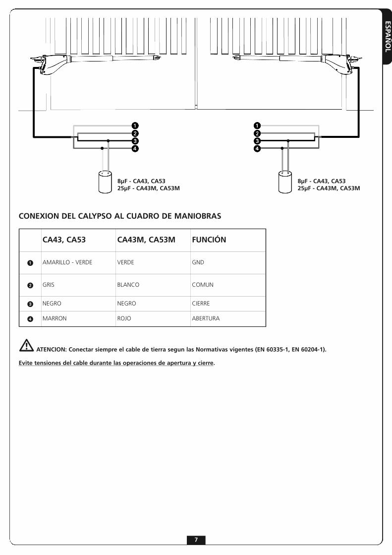
CONEXION DEL CALYPSO AL CUADRO DE MANIOBRAS
m ATENCION: Conectar siempre el cable de tierra segun las Normativas vigentes (EN 60335-1, EN 60204-1).
Evite tensiones del cable durante las operaciones de apertura y cierre.
CA43, CA53 CA43M, CA53M FUNCIÓN
� AMARILLO - VERDE VERDE GND
� GRIS BLANCO COMUN
� NEGRO NEGRO CIERRE
� MARRON ROJO ABERTURA
8μF - CA43, CA5325μF - CA43M, CA53M
8μF - CA43, CA5325μF - CA43M, CA53M

ESPA
ÑO
L
8
DESBLOQUEO DE EMERGENCIA
En caso de falta de corriente eléctrica, la puertapuede ser desbloqueada interviniendo sobre elmotor. Insertar la llave en dotación en lacerradura presente en el lado frontal del motory realizar 1/2 de giro. Para restablecer la automatización es suficienterotar nuevamente la llave en posición de cierre ycubrir la cerradura con la protección de plásticocorrediza.

FRA
NÇ
AIS
9
CONSEILS IMPORTANTS
ERREKA se réserve le droit d’apporter d’éventuellesmodifications au produit sans préavis; elle décline en outretoute responsabilité pour tous types de dommages auxpersonnes ou aux choses dus à une utilisation imporopreou à une mauvaise installation.
m Avant de proceder avec l'installation et la progarmmation, lire attentivement les notices.
• Ce manuel d'instruction est destiné à des techniciens qualifiés dans le domain des automatismes.
• Aucune des informations contenues dans ce livret pourra être utile pour le particulier.
• Tous operations de maintenance ou programation doivent être faites à travers de techniciens qualifiés.
L’AUTOMATION DOIT ÊTRE RÉALISÉE CONFORMÉMENT AUXDISPOSITIFS NORMATIFS EUROPÉENS EN VIGUEUR:
EN 60204-1 (Sécutité de la machinerie. Équipement électriquedes machines, partie 1: régles générales).
EN 12445 (Sécutité dans lìutilisation de fermetures automatisées, méthodes d'essai).
EN 12453 (Sécurité dans l'utilisation de fermetures automatisées, conditions requises).
• L'installateur doit pourvoir à l'installation d'un dispositif (ex. interrupteur magnétothermique) qui assure la coupure omnipolaire de l'équipement du réseau d'alimentation. La norme requiert une séparation des contacts d'au moins 3 mm pour chaque pôle (EN 60335-1).
• L'enveloppe en plastique de la carte possède une protection IP55, pour la connexion de tubes rigides ou flexibles utiliser des raccordements possédant le même niveau de protection.
• L’installation requiert des compétences en matière d’électricité et mécaniques; doit être faite exclusivement par techniciens qualifiés en mesure de délivrer l’attestation de conformité pour l’installation (Directive 2006/42/CEE, - IIA).
• Il est obligatoire se conformer aux normes suivantes pour fermetures véhiculaires automatisées: EN 13241-1, EN 12453, EN 12445 et à toutes éventuelles prescriptions nationales.
• Même l’installation électrique ou on branche l’automatisme doit répondre aux normesen vigueur et être fait à règles de l’art.
• La régulation de la force de poussée du vantail doit être mesurée avec outil spécial et réglée selon les valeurs maxi admis par la norme EN 12453.
• Nous conseillons d’utiliser un poussoir d’urgence à installer près de l’automatisme (branché à l’entrée STOP de l’armoire de commande de façon qui soit possible l’arrêt immédiat du portail en cas de danger.
• L'appareillage ne doit pas être utilisé par des enfants ou des personnes affectés d'handicaps physiques et/ou psychiques, sans la nécessaire connaissance ou supervision de la part d'une personne compétente.
• Veillez à ce que les enfants ne puissent jouer avec l'appareillage.
DÉCLARATION D'INCORPORATION POUR LES QUASI-MACHINES (Directive 2006/42/CE, Annexe II-B)
Le fabricant (*) Matz-Erreka,S.Coop. , ayant son siège social a:Bº Ibarreta s/n, 20577 Antzuola (Gipuzkoa), España
Déclare sous sa propre responsabilité que: l’automatisme modèle: CA43 (*), CA53 (*), CA43M (*), CA53M (*)
Numéro de fabrication et année de construction: positionnéssur la plaque de donnéesDescription: actionneur électromécanique pour portails
• a été conçu pour être incorporé dans un portail garage en vue de former une machine conformément à la Directive 2006/42/CE.Cette machine ne pourra pas être mise en service avant d'être déclarée conforme aux dispositions de la directive 2006/42/CE (Annexe II-A)
• est conforme exigences essentielles applicables des Directives: Directive Machines 2006/42/CE (Annexe I, Chapitre 1)Directive basse tension 2006/95/CE Directive compatibilité électromagnétique 2004/108/CE
La documentation technique est à disposition de l'autoritécompétente sur demande motivée à l'adresse suivante: Matz-Erreka S.Coop.Bº Ibarreta s/n, 20577 Antzuola (Gipuzkoa), España
La personne autorisée à signer la présente déclarationd'incorporation et à fournir la documentation technique est : Roberto CoreraBusiness ManagerAntzuola, le 17/10/2011
(*) produit fabriqué hors UE pour Matz-Erreka,S.Coop.

FRA
NÇ
AIS
10
CARACTERISTIQUES TECHNIQUES
CALYPSO 400CA43, CA43M
CALYPSO 500CA53, CA53M
A 819 944
B 762 887
C 1162 1387
CA43 CA53 CA43M CA53M
Longuer maxi du battant m 2,5 3 2,5 3
Poids maxi du battant Kg 400 500 400 500
Alimentation VAC - Hz 230 - 50 230 - 50 120 - 60 120 - 60
Absorption à vide A 0,8 0,8 2 2
Absorption maximum A 1 1 2,8 2,8
Puissance maximum W 200 200 300 300
Condensateur µF 8 8 25 25
Course maxi d'entrainement mm 400 500 400 500
Vitesse de traction m/s 0,016 0,016 0,018 0,018
Pousée maximum N 2300 2300 2300 2300
Température de service °C -30 ÷ +50 -30 ÷ +50 -30 ÷ +50 -30 ÷ +50
Indìce de protection IP 44 44 44 44
Cycle de travail % 30 30 30 30
Poids moteur Kg 6,5 6,8 6,5 6,8

FRA
NÇ
AIS
11
SCHÉMA D’INSTALLATION
OPÉRATIONS PRÉLIMINAIRESCe nouvelle série des opérateurs électromécaniques CALYPSO, a été crée pour automatiser portails à battant jusqu’à 500 Kg de poids etvantail de 3m selon les models (voir tableau caractéristiques techniques). Avant de procéder à l'installation il est fondamental de s'assurerque votre portail s'ouvre et se referme sans problème et de vérifier scrupuleusement les points suivants:
• Gonds et tourillons en très bon état et graissés opportunément.• Aucune entrave ne doit empêcher le mouvement.• Aucun frottement contre le sol et entre les vantaux.• Votre portail doit être équipé d'arrêts central � et latéraux �: ceux-ci sont indispensables pour un bon fonctionnement du système.
� Actuador CALYPSO câble 4 x 1 mm2
� Clignotant câble 2 x 1,5 mm2
� Antenne radio câble RG-58
� Selecteur à clé ou digital câble 2 x 1 mm2
� Photocellules internecâble 4 x 1 mm2 (RX)câble 2 x 1 mm2 (TX)
� Photocellules externecâble 4 x 1 mm2 (RX)câble 2 x 1 mm2 (TX)
� Barre palpeuse de sécurité (EN 12978) -
� Armoire de commande câble 3 x 1,5 mm2

FRA
NÇ
AIS
CALYPSO 400 (CA43, CA43M)
γ A [mm] B [mm] C [mm] F [mm]
90°
20 130 130 101040 150 140 100060 170 150 99080 190 150 980100 200 150 980120 210 140 980140 250 120 1010
100°
20 130 170 97040 150 180 96060 170 180 96080 190 170 970100 210 140 990
110°20 130 190 95040 150 180 96050 160 170 970
CALYPSO 500 (CA53, CA53M)
γ A [mm] B [mm] C [mm] F [mm]
90°
20 130 170 120040 150 180 119060 170 180 119080 190 190 1180100 210 190 1170120 230 190 1170140 250 180 1170160 270 190 1170180 290 170 1180
100°
20 130 160 121040 150 170 120060 170 170 120080 200 180 1190100 210 170 1190120 230 190 1170140 250 180 1180160 270 160 1200170 280 160 1200
110°
20 130 170 120040 150 180 119060 170 180 119080 190 190 1180100 210 200 1170110 220 200 1170
OUVERTURE VERS L’INTERIEUR
MESURES D’INSTALLATIONPour effectuer une bonne installation des actionneurs et garantir un fonctionnement optimal de l'automatisation il est nécessaire derespecter leniveaux de mesure reproduits dans le tableau ci-dessous. Modifier le cas échéant la structure du portail de manière à l'adapter à l'un des cas de figure énoncés dans le tableau.
m ATTENTION: Les vantaux de plus de 2 m de langeur nécessitent l'installation d'une élettroserrure pou garantir une fermeture efficace.
12

FRA
NÇ
AIS
13
OUVERTURE VERS L’EXTERIEUR
CALYPSO 400 (CA43, CA43M)
γ A [mm] B [mm] C [mm] F [mm]
80° 30 110 ÷ 130 90 949
85° 30 110 ÷ 130 100 967
90° 30 110 ÷ 130 110 986
95° 30 110 ÷ 130 120 1006
100° 30 110 ÷ 130 130 1027
110° 30 110 ÷ 130 140 1057
CALYPSO 500 (CA53, CA53M)
γ A [mm] B [mm] C [mm] F [mm]
80° 30 130 100 995
85° 30 130 110 1005
90° 30 130 120 1015
95° 30 130 130 1025
100° 30 130 140 1035
110° 30 130 150 1045

FRA
NÇ
AIS
14
POUR FIXER LES ACTIONNEURSAprès avoir noté sur les piliers les dimensions souhaitées dans letableau de la page précédente, procéder avec les opérationssuivantes: • Fixer les étriers sur les piliers et sur le portail en les soudant directement ; si les matériaux ne le permettent pas, il est nécessaire souder les étriers sur des plaques à fixer au portail et aux piliers par des tampons ou des vis.
• Fermer le vantail.• Déverrouiller l’opérateur.• Mettre le CALYPSO sur les pattes et fixer les goujons 1 et 2 avec les dés auto bloquants selon la figure.
• Tester l’ouverture du battant manuellement, elle doit se faire librement sans le moindre obstacle.
m ATTENTION: pour ne pas dommager l'actuateur il faut imperativement respecter les CONDITIONS SUIVANTES:
• Les étrieres doivent être positionnées à la même hauteur
• La course maximum du bras A (avec portail completement fermé) ne doit pas être supérieure à 456 mm pour le CALYPSO400 (CA43, CA43M) et 556 mm pour le CALYPSO500 (CA53, CA53M).
• La course minimum du bras B (avec portail completement ouvert) ne doit pas être inferieure à 56 mm.
FRA
NÇ
AIS
15
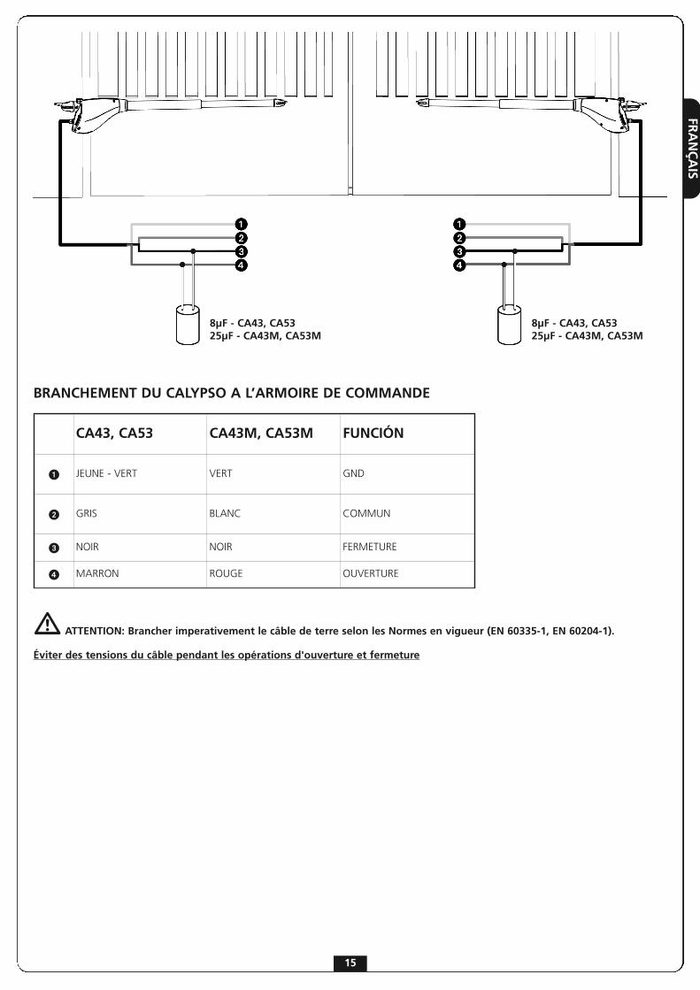
BRANCHEMENT DU CALYPSO A L’ARMOIRE DE COMMANDE
m ATTENTION: Brancher imperativement le câble de terre selon les Normes en vigueur (EN 60335-1, EN 60204-1).
Éviter des tensions du câble pendant les opérations d'ouverture et fermeture
8μF - CA43, CA5325μF - CA43M, CA53M
8μF - CA43, CA5325μF - CA43M, CA53M
CA43, CA53 CA43M, CA53M FUNCIÓN
� JEUNE - VERT VERT GND
� GRIS BLANC COMMUN
� NOIR NOIR FERMETURE
� MARRON ROUGE OUVERTURE

FRA
NÇ
AIS
16
MANOEUVRE DE SECOURS
En cas de coupure du courant électrique, leportail peut être débloqué en agissant sur lemoteur. Introduire la clef fournie dans la serrurequi se trouve sur le côté avant du moteur,effectuer 1/2 de tour.Pour re verrouiller le moteur il suffit tourner ànouveau la clef dans sa position de fermeture etrecouvrir la serrure avec la protection enplastique prévue à cet effet.
ENG
LISH
17
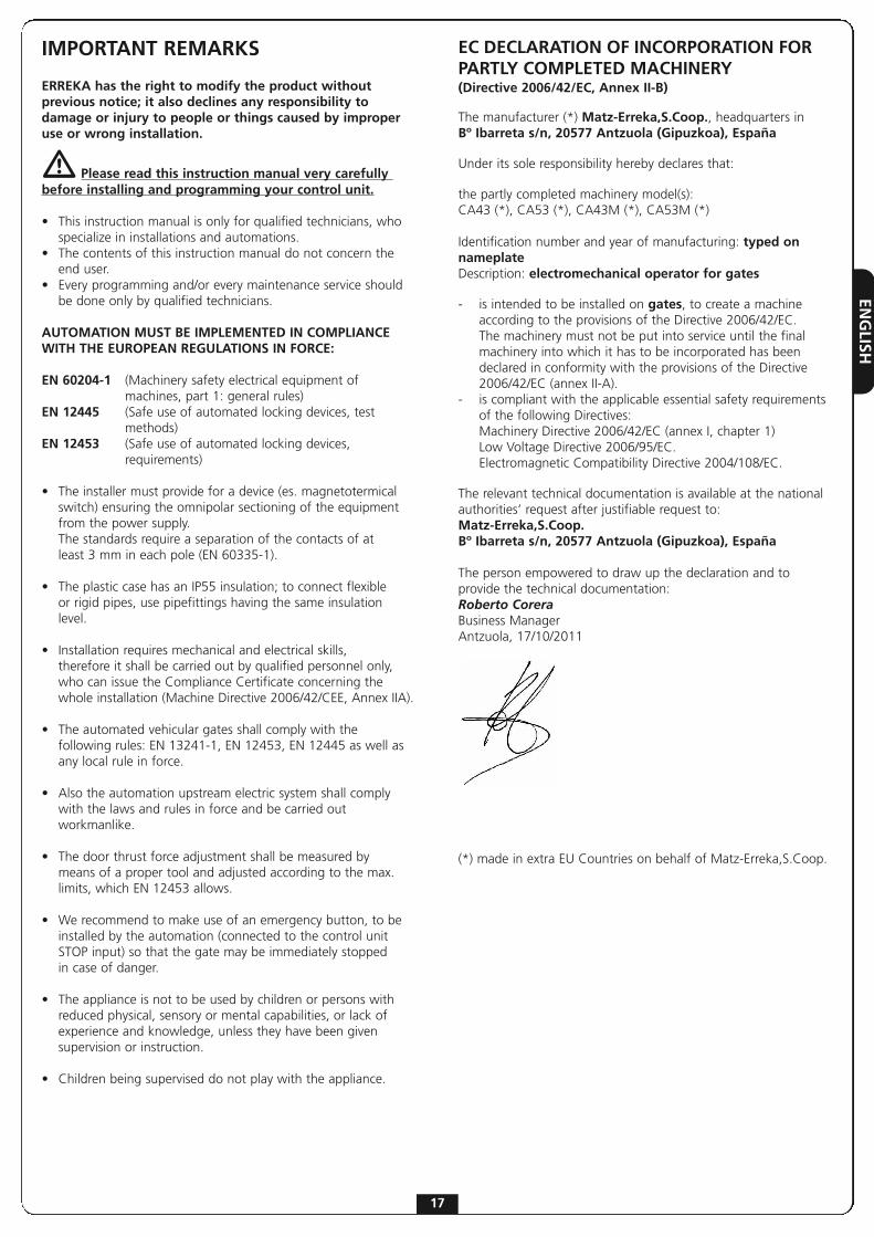
IMPORTANT REMARKS
ERREKA has the right to modify the product withoutprevious notice; it also declines any responsibility todamage or injury to people or things caused by improperuse or wrong installation.
m Please read this instruction manual very carefully before installing and programming your control unit.
• This instruction manual is only for qualified technicians, who specialize in installations and automations.
• The contents of this instruction manual do not concern the end user.
• Every programming and/or every maintenance service should be done only by qualified technicians.
AUTOMATION MUST BE IMPLEMENTED IN COMPLIANCEWITH THE EUROPEAN REGULATIONS IN FORCE:
EN 60204-1 (Machinery safety electrical equipment of machines, part 1: general rules)
EN 12445 (Safe use of automated locking devices, test methods)
EN 12453 (Safe use of automated locking devices, requirements)
• The installer must provide for a device (es. magnetotermical switch) ensuring the omnipolar sectioning of the equipment from the power supply.The standards require a separation of the contacts of at least 3 mm in each pole (EN 60335-1).
• The plastic case has an IP55 insulation; to connect flexible or rigid pipes, use pipefittings having the same insulation level.
• Installation requires mechanical and electrical skills, therefore it shall be carried out by qualified personnel only,who can issue the Compliance Certificate concerning the whole installation (Machine Directive 2006/42/CEE, Annex IIA).
• The automated vehicular gates shall comply with the following rules: EN 13241-1, EN 12453, EN 12445 as well as any local rule in force.
• Also the automation upstream electric system shall comply with the laws and rules in force and be carried out workmanlike.
• The door thrust force adjustment shall be measured by means of a proper tool and adjusted according to the max. limits, which EN 12453 allows.
• We recommend to make use of an emergency button, to be installed by the automation (connected to the control unit STOP input) so that the gate may be immediately stopped in case of danger.
• The appliance is not to be used by children or persons with reduced physical, sensory or mental capabilities, or lack of experience and knowledge, unless they have been given supervision or instruction.
• Children being supervised do not play with the appliance.
EC DECLARATION OF INCORPORATION FORPARTLY COMPLETED MACHINERY(Directive 2006/42/EC, Annex II-B)
The manufacturer (*) Matz-Erreka,S.Coop., headquarters inBº Ibarreta s/n, 20577 Antzuola (Gipuzkoa), España
Under its sole responsibility hereby declares that:
the partly completed machinery model(s): CA43 (*), CA53 (*), CA43M (*), CA53M (*)
Identification number and year of manufacturing: typed onnameplate Description: electromechanical operator for gates
- is intended to be installed on gates, to create a machine according to the provisions of the Directive 2006/42/EC. The machinery must not be put into service until the final machinery into which it has to be incorporated has been declared in conformity with the provisions of the Directive 2006/42/EC (annex II-A).
- is compliant with the applicable essential safety requirements of the following Directives:Machinery Directive 2006/42/EC (annex I, chapter 1)Low Voltage Directive 2006/95/EC.Electromagnetic Compatibility Directive 2004/108/EC.
The relevant technical documentation is available at the nationalauthorities’ request after justifiable request to:Matz-Erreka,S.Coop.Bº Ibarreta s/n, 20577 Antzuola (Gipuzkoa), España
The person empowered to draw up the declaration and toprovide the technical documentation:Roberto CoreraBusiness ManagerAntzuola, 17/10/2011
(*) made in extra EU Countries on behalf of Matz-Erreka,S.Coop.
ENG
LISH
18
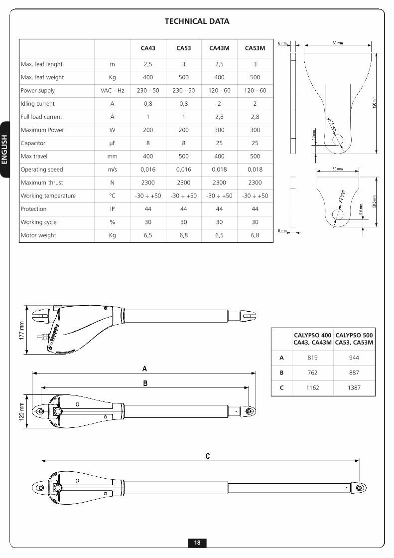
TECHNICAL DATA
CALYPSO 400CA43, CA43M
CALYPSO 500CA53, CA53M
A 819 944
B 762 887
C 1162 1387
CA43 CA53 CA43M CA53M
Max. leaf lenght m 2,5 3 2,5 3
Max. leaf weight Kg 400 500 400 500
Power supply VAC - Hz 230 - 50 230 - 50 120 - 60 120 - 60
Idling current A 0,8 0,8 2 2
Full load current A 1 1 2,8 2,8
Maximum Power W 200 200 300 300
Capacitor µF 8 8 25 25
Max travel mm 400 500 400 500
Operating speed m/s 0,016 0,016 0,018 0,018
Maximum thrust N 2300 2300 2300 2300
Working temperature °C -30 ÷ +50 -30 ÷ +50 -30 ÷ +50 -30 ÷ +50
Protection IP 44 44 44 44
Working cycle % 30 30 30 30
Motor weight Kg 6,5 6,8 6,5 6,8

ENG
LISH
19
INSTALLATION LAYOUT
PREPARATORY STEPSThe new series of operators CALYPSO, has been devised to serve gates up to 500 Kg with leaf up to 3 meters wide (look at the tabletechnical data). Before proceeding with the installation, please make sure that your gate opens and closes freely, and that:
• Hinges and pins are in optimum condition and properly greased.• No obstacles are within the moving area.• There is no friction with the ground or between the leaves.• Your gate shall be equipped with central � and side � stops, which are fundamental for the good system operation.
� CALYPSO operator cable 4 x 1 mm2
� Blinker cable 2 x 1,5 mm2
� Aerial cable RG-58
� Key or digital selector cable 2 x 1 mm2
� Internal photocellscable 4 x 1 mm2 (RX)cable 2 x 1 mm2 (TX)
� External photocellscable 4 x 1 mm2 (RX)cable 2 x 1 mm2 (TX)
� Safety edge (EN 12978) -
� Control unit cable 3 x 1,5 mm2

ENG
LISH
CALYPSO 400 (CA43, CA43M)
γ A [mm] B [mm] C [mm] F [mm]
90°
20 130 130 101040 150 140 100060 170 150 99080 190 150 980100 200 150 980120 210 140 980140 250 120 1010
100°
20 130 170 97040 150 180 96060 170 180 96080 190 170 970100 210 140 990
110°20 130 190 95040 150 180 96050 160 170 970
CALYPSO 500 (CA53, CA53M)
γ A [mm] B [mm] C [mm] F [mm]
90°
20 130 170 120040 150 180 119060 170 180 119080 190 190 1180100 210 190 1170120 230 190 1170140 250 180 1170160 270 190 1170180 290 170 1180
100°
20 130 160 121040 150 170 120060 170 170 120080 200 180 1190100 210 170 1190120 230 190 1170140 250 180 1180160 270 160 1200170 280 160 1200
110°
20 130 170 120040 150 180 119060 170 180 119080 190 190 1180100 210 200 1170110 220 200 1170
INWARD OPENING
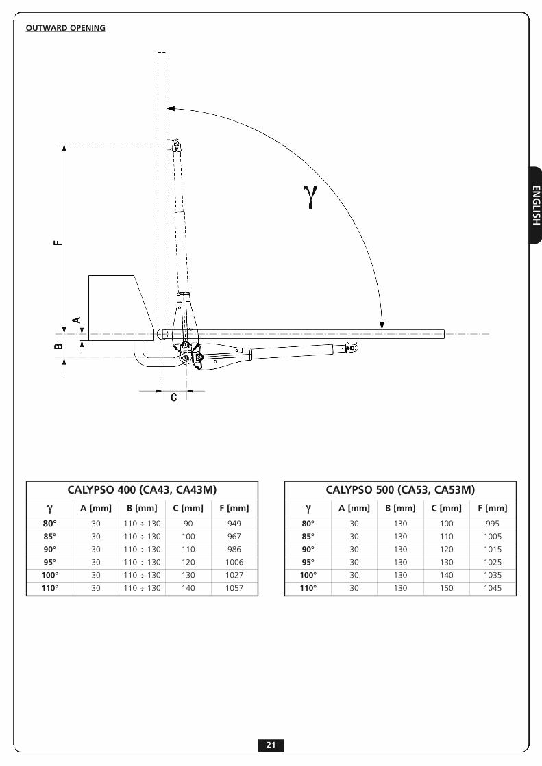
INSTALLATION MEASURESTo carry out a proper installation of the operator parts as well as to ensure the best automation performance, the measurement levelsshown in the following table shall be complied with. Change the gate structure to adapt it to one of the cases in the table, if necessary.
m WARNING: In the case of leaf longer than 2 metres, an electric lock must be fitted to ensure an efficent closig.
20
ENG
LISH
21
OUTWARD OPENING
CALYPSO 400 (CA43, CA43M)
γ A [mm] B [mm] C [mm] F [mm]
80° 30 110 ÷ 130 90 949
85° 30 110 ÷ 130 100 967
90° 30 110 ÷ 130 110 986
95° 30 110 ÷ 130 120 1006
100° 30 110 ÷ 130 130 1027
110° 30 110 ÷ 130 140 1057
CALYPSO 500 (CA53, CA53M)
γ A [mm] B [mm] C [mm] F [mm]
80° 30 130 100 995
85° 30 130 110 1005
90° 30 130 120 1015
95° 30 130 130 1025
100° 30 130 140 1035
110° 30 130 150 1045

ENG
LISH
22
OPERATOR FIXINGChoose measures referring to the table you can find in theprevious page, mark them on the pillars and continue as follows:• Fix the clamps to the pillar and to the gate soldering directly; if the material does not allow it, it is necessary to solder the clamps to plates to be fixed to the gate and the pillars by screws.
• Close the swing.• Unlock the operators.• Position CALYPSO on the brackets and fix the pins no. 1 and no. 2 with seeger (see the picture).
• Open and close the swings repeatedly manually to verify the absence of frictions between gate and ground.
m WARNING: in order to avoid damage to the operator, please adhere to the following conditions:
• The brackets must be installed at the same height.
• The maximum stroke of arm A should not exceed 456 mm for CALYPSO400 (CA43, CA43M) and 556 mm for CALYPSO500 (CA53, CA53M) (in case of gate completely closed).
• The minimum stroke of arm B must be more than 56 mm (in case of gate completely open).
ENG
LISH
23
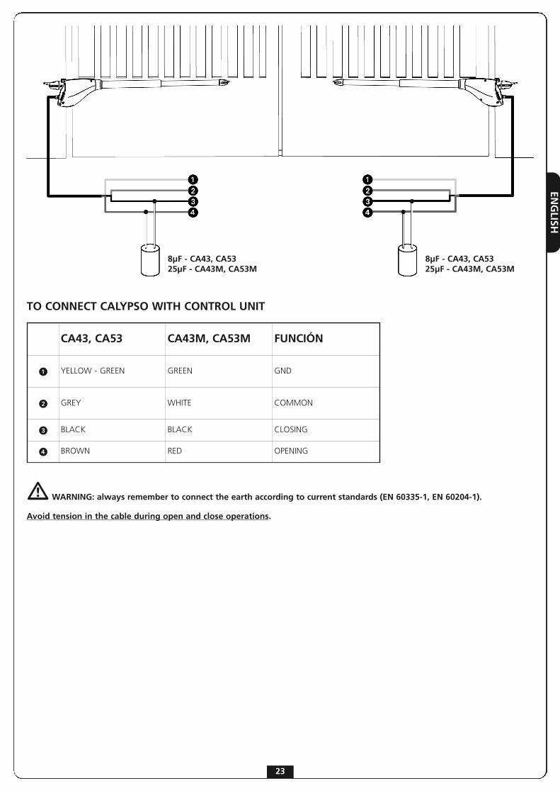
TO CONNECT CALYPSO WITH CONTROL UNIT
m WARNING: always remember to connect the earth according to current standards (EN 60335-1, EN 60204-1).
Avoid tension in the cable during open and close operations.
8μF - CA43, CA5325μF - CA43M, CA53M
8μF - CA43, CA5325μF - CA43M, CA53M
CA43, CA53 CA43M, CA53M FUNCIÓN
� YELLOW - GREEN GREEN GND
� GREY WHITE COMMON
� BLACK BLACK CLOSING
� BROWN RED OPENING

ENG
LISH
24
EMERGENCY RELEASE
In case of a blackout, the gate can be operateddirectly from the motor. Insert the key suppliedin the lock, perform 1/2 of a turn.To restore the automation, simply rotate the keyin closed position and insert the provided plasticcover onto the lock.

POR
TUG
UÊS
25
AVISOS IMPORTANTES
ERREKA reserva-se o direito de efectuar eventuaisalterações ao produto sem aviso prévio; declina aindaqualquer responsabilidade pelos danos a pessoas ou coisasoriginados por uso impróprio ou instalação errada.
m LER ATENTAMENTE O SEGUINTE MANUAL DE INSTRUÇÕES ANTES DE PROCEDER à INSTALAÇÃO.
• O presente manual de instruções destina-se exclusivamente ao pessoal técnico qualificado no sector das instalações de automações.
• Nenhuma das informações contidas no manual pode ser interessante o útil ao utilizador final.
• Qualquer operação de manutenção ou de programação deve ser realizada exclusivamente por pessoal qualificado.
A AUTOMAÇÃO DEVE SER REALIZADA EM CONFORMIDADECOM AS NORMAS EUROPEIAS VIGENTES:EN 60204-1 (Segurança das máquinas, equipamento
eléctrico das máquinas, parte 1: regras gerais).EN 12445 (Segurança nos cerramentos automatizados,
métodos de teste).EN 12453 (Segurança no uso de cerramentos
automatizados, requisitos).
• O instalador deve instalar um dispositivo (ex. interruptor térmico magnético), que assegure o seccionamento de todos os pólos do sistema da rede de alimentação. As normas exigem uma separação dos contactos de pelo menos 3 mm em cada polo (EN 60335-1).
• Para a conexão dos tubos rijos e flexíveis ou passador de cabos, utilizar junções conformes ao grau de protecção IP55 ou superior.
• A instalação requer competências no sector eléctrico e mecânico; só deve ser efectuada por pessoal qualificado habilitado a passar a declaração de conformidade de tipo A para a instalação completa (Directriz máquinas 2006/42/CEE, apenso IIA).
• É obrigatório respeitar as seguintes normas para cerramentos veiculares automatizados: EN 13241-1, EN 12453, EN 12445 e as eventuais prescrições nacionais.
• A instalação a montante da automação também deve respeitar as normas vigentes e ser realizadas conforme as regras da arte.
• A regulação da força de impulso da folha deve medir-se com ferramenta própria e ser regulada conforme os valores máximos admitidos pela norma EN 12453.
• Aconselhamos utilizar um botão de emergência, a ser instalado nas proximidades da automação, (conectado com a entrada STOP da placa de comando) de maneira que seja possível parar imediatamente o portão no caso de perigo.
• A aparelhagem não deve ser utilizada por crianças ou pessoas com deficiências físicas ou psíquicas sem o devido conhecimento ou supervisão de pessoa competente.
• Não deixe as crianças brincarem com a aparelhagem.
• Se o cabo de alimentação estiver danificado, a sua substituição deverá ser feita pelo fabricante, pelo seu serviço de assistência ou, em todo caso, por pessoa com qualificação similar, de maneira a prevenir qualquer risco.
DECLARAÇÃO DE INCORPORAÇÃO PARA AS QUASE-MÁQUINAS (Directiva 2006/42/CE, Anexo II-B)
O fabricante (*) Matz-Erreka,S.Coop., com sede emBº Ibarreta s/n, 20577 Antzuola (Gipuzkoa), España
Declara sob a própria responsabilidade que:O automatismo modelo: CA43 (*), CA53 (*), CA43M (*), CA53M (*)
Matrícula e ano de fabricação : referidos na chapa de dadosDescrição: Accionador electromecânico para portões
- Destina-se a ser incorporada em portão para constituir uma máquina nos termos da Directiva 2006/42/CE.A máquina não pode entrar em exercício antes de ser declarada conforme às disposições da directiva 2006/42/CE (Anexo II-A)
- É conforme aos requisitos essenciais aplicáveis das Directivas :Directiva Máquinas 2006/42/CE (Anexo I, Capítulo 1)Directiva baixa tensão 2006/95/CEDirectiva compatibilidade electromagnética 2004/108/CE
A documentação técnica está à disposição da autoridadecompetente a pedido motivado junto à:Matz-Erreka,S.Coop.Bº Ibarreta s/n, 20577 Antzuola (Gipuzkoa), España
A pessoa autorizada a assinar a presente declaração deincorporação e a fornecer a documentação técnica:Roberto CoreraBusiness ManagerAntzuola, 17/10/2011
(*) produto fabricado fora da UE para Matz-Erreka,S.Coop.

POR
TUG
UÊS
26
CARACTERÍSTICAS TÉCNICAS
CALYPSO 400CA43, CA43M
CALYPSO 500CA53, CA53M
A 819 944
B 762 887
C 1162 1387
CA43 CA53 CA43M CA53M
Comprimento máximo porta m 2,5 3 2,5 3
Peso máximo porta Kg 400 500 400 500
Energia Eléctrica VAC - Hz 230 - 50 230 - 50 120 - 60 120 - 60
Absorção a vácuo A 0,8 0,8 2 2
Absorção máxima A 1 1 2,8 2,8
Potência motor W 200 200 300 300
Condensador µF 8 8 25 25
Curso máximo de arrastamento mm 400 500 400 500
Velocidade de arrastamento m/s 0,016 0,016 0,018 0,018
Impulso máximo N 2300 2300 2300 2300
Température de fonctionnement °C -30 ÷ +50 -30 ÷ +50 -30 ÷ +50 -30 ÷ +50
Grau de protecção IP 44 44 44 44
Ciclo de trabalho % 30 30 30 30
Peso motor Kg 6,5 6,8 6,5 6,8

POR
TUG
UÊS
27
ESQUEMA DE INSTALAÇÃO
OPERAÇÕES PRELIMINARES A nova série de accionadores CALYPSO foi estudada para automatizar portões a batente com peso de até 500 Kg, com folhas de até 3 m de comprimento, consoante os modelos (ver tabela características técnicas). Antes de iniciar a instalação é fundamental apurar que oportão se abre e fecha livremente e verificar escrupulosamente os seguintes pontos:
• Dobradiças e pinos em óptimo estado e bem lubrificados.• Não deve existir nenhum empecilho a impedir o movimento.• Não deve haver nenhum atrito com o solo e entre as folhas.• O portão deve ser dotado de paragem central � e paragens laterais �: estas são indispensáveis para um bom
� Accionador CALYPSO cabo 4 x 1 mm2
� Intermitência cabo 2 x 0.5 mm2
� Antena cabo RG-58
� Selector com chave, teclado digital ou leitor de proximidade
cabo 2 x 1 mm2
� Células fotoeléctricas internascabo 4 x 1 mm2 (RX)cabo 2 x 1 mm2 (TX)
� Células fotoeléctricas externascabo 4 x 1 mm2 (RX)cabo 2 x 1 mm2 (TX)
� Banda de seguridad (EN 12978) -
� Armoire de commande cabo 3 x 1,5 mm2

POR
TUG
UÊS
CALYPSO 400 (CA43, CA43M)
γ A [mm] B [mm] C [mm] F [mm]
90°
20 130 130 101040 150 140 100060 170 150 99080 190 150 980100 200 150 980120 210 140 980140 250 120 1010
100°
20 130 170 97040 150 180 96060 170 180 96080 190 170 970100 210 140 990
110°20 130 190 95040 150 180 96050 160 170 970
CALYPSO 500 (CA53, CA53M)
γ A [mm] B [mm] C [mm] F [mm]
90°
20 130 170 120040 150 180 119060 170 180 119080 190 190 1180100 210 190 1170120 230 190 1170140 250 180 1170160 270 190 1170180 290 170 1180
100°
20 130 160 121040 150 170 120060 170 170 120080 200 180 1190100 210 170 1190120 230 190 1170140 250 180 1180160 270 160 1200170 280 160 1200
110°
20 130 170 120040 150 180 119060 170 180 119080 190 190 1180100 210 200 1170110 220 200 1170
ABERTURA PARA O INTERIOR
MEDIDAS DE INSTALAÇÃOPara efectuar uma correcta instalação dos accionadores e garantir um funcionamento perfeito da automatização, é necessário respeitar ascotas de medição referidas na tabela abaixo. Eventualmente, modificar a estrutura do portão de maneira a adaptá-lo a um dos casosreferidos na tabela abaixo.
m ATENÇÃO: No caso em que a folha tenha um comprimento superior aos 2 m é necessário instalar uma fechadura eléctrica para garantir uma fechadura.
28
POR
TUG
UÊS
29
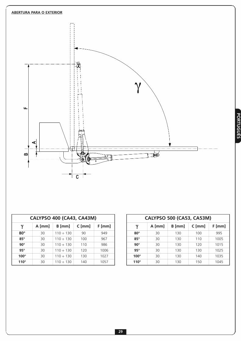
ABERTURA PARA O EXTERIOR
CALYPSO 400 (CA43, CA43M)
γ A [mm] B [mm] C [mm] F [mm]
80° 30 110 ÷ 130 90 949
85° 30 110 ÷ 130 100 967
90° 30 110 ÷ 130 110 986
95° 30 110 ÷ 130 120 1006
100° 30 110 ÷ 130 130 1027
110° 30 110 ÷ 130 140 1057
CALYPSO 500 (CA53, CA53M)
γ A [mm] B [mm] C [mm] F [mm]
80° 30 130 100 995
85° 30 130 110 1005
90° 30 130 120 1015
95° 30 130 130 1025
100° 30 130 140 1035
110° 30 130 150 1045

POR
TUG
UÊS
30
FIXAÇÃO DOS ACCIONADORESApós ter transferido nos pilares as medidas escolhidas na tabelada página anterior, proceder com as seguintes operações:
• Fixar os estribos aos pilares e ao portão e soldá-los directamente; se os materiais não o permitirem, então será necessário soldar os estribos sobre chapas a serem sucessivamente fixadas aos pilares com parafusos ou parafusos de expansão.
• Fechar a folha.• Desbloquear os accionadores.• Posicionar o CALYPSO nos estribos e fixar os pinos 1 e 2 com os respectivos seeger como mostra a figura.
• Ensaiar diversas vezes a abertura e o cerramento manual das folhas, prestando atenção que não haja atrito entre o accionador e a estrutura do portão.
m ATENÇÃO: para não danificar o accionador é fundamental RESPEITAR AS SEGUINTES CONDIÇÕES:
• Os estribos devem ser posicionados na mesma altura.
• O curso máximo da barra A (com o portão completamente fechado) não deve ultrapassar os 456 mm para CALYPSO400 (CA43, CA43M) e os 556 mm para CALYPSO500 (CA53, CA53M).
• O percurso mínimo da haste B (com o portão completamente aberto) não deve ser inferior a 56 mm.

POR
TUG
UÊS
31
LIGAÇÃO DO CALYPSOà CENTRAL DE COMANDO
m ATENÇÃO: Ligar sempre o cabo de terra como previsto pelas normas vigentes (EN 60335-1, EN 60204-1).
Evitar a tensão do cabo durante as operações de abertura e fecho.
8μF - CA43, CA5325μF - CA43M, CA53M
8μF - CA43, CA5325μF - CA43M, CA53M
CA43, CA53 CA43M, CA53M FUNCIÓN
� AMARELO - VERDE VERDE GND
� CINZA BLANCO COMUM
� PRETO PRETO CERRAMENTO
� MARROM VERMELHO ABERTURA

POR
TUG
UÊS
32
DESBLOQUEIO DE EMERGÊNCIA
No caso de faltar energia eléctrica o portãopode ser desbloqueado mecanicamenteactuando no motor. Inserir a chave fornecida eefectuar 1/2 giro. Para voltar à automação basta girar novamentea chave na posição inicial e inserir a tampa deplástico.

DEU
TSCH
33
WICHTIGE HINWEISE
Die Firma ERREKA behält sich das Recht vor, das Produktohne vorherige Ankündigungen abzuändern; dieÜbernahme der Haftung für Schäden an Personen oderSachen, die auf einen unsachgemäßen Gebrauch oder einefehlerhafte Installation zurückzuführen sind, wirdabgelehnt.
m Um die Steuerung fehlerfrei zu installieren und programmieren zu können, lesen Sie bitte dieseBedienungsanleitung sehr aufmerksam durch.
• Diese Bedienungsanleitung ist nur für Fachtechniker, die auf Installationen und Automationen von Toren.
• Keine Information dieser Bedienungsanleitung ist für den Endbenutzer nützlich.
• Jede Programmierung und/oder jede Wartung sollte nur von geschulten Technikern vorgenommen werden.
DIE AUTOMATISIERUNG MUSS IN ÜBEREINSTIMMUNG MITDEN GELTENDEN EUROPÄISCHEN NORMEN ERFOLGEN:EN 60204-1 (Sicherheit der Maschine elektrische
Ausrüstungen von Maschinen, Teil 1: allgemeine Anforderungen)
EN 12445 (Nutzungssicherheit kraftbetätigter Tore rüfverfahren)
EN 12453 (Nutzungssicherheit kraftbetätigter Tore Anforderungen)
• Der Installateur muss eine Vorrichtung (z.B. thermomagn. Schalter) anbringen, die Trennung aller Pole des Geräts zum Versorgungsnetz garantiert. Die Norm verlangt eine Trennung der Kontakte von mindestens 3 mm an jedem Pol (EN 60335-1).
• Für den Anschluss von Rohren und Schläuchen oder Kabeldurchgängen sind Verbindungen zu verwenden, die dem Sicherungsgrad IP55 entsprechen.
• Die Installation erfordert Kenntnisse auf den Gebieten der Elektrik und Mechanik; sie darf ausschließlich von kompetentem Personal durchgeführt werden, welches berechtigt ist, eine vollständige Konformitätserklärung vom Typ A auszustellen (Maschinenrichtlinie 2006/42/CEE, Anlage IIA).
• Für automatisch betriebene Rolltore ist die Einhaltung der folgenden Normen obligatorisch: EN 13241-1, EN 12453, EN 12445 und alle eventuell geltenden, regionalen Vorschriften.
• Auch die elektrische Anlage der Automatik muss den geltenden Normen genügen, und fachgerecht installiert werden.
• Die Schubkraft des Torflügels muss mit Hilfe eines geeigneten Instruments gemessen, und entsprechend den in Richtlinie EN 12453 definierten Höchstwerten eingestellt werden.
• Es wird empfohlen, in der Nähe der Automatik einen Notaus-Schalter zu installieren (mit Anschluss an en Eingang STOP der Steuerkarte), so dass bei Gefahr ein unverzügliches Halten des Tors bewirkt werden kann.
• Das Gerät darf nicht von körperlich oder psychisch behinderten Kindern oder Personen ohne entsprechende Kenntnisse oder Aufsicht seitens einer kompetenten Person betätigt werden.
• Kinder so beaufsichtigen, dass sie nicht mit dem Gerät spielen.
INKORPORATIONSERKLÄRUNG FÜR UNVOLLSTÄNDIGE MASCHINEN(Richtlinie 2006/42/EG, Anhang II-B)
Der Hersteller (*) Matz-Erreka,S.Coop. , mit Sitz inBº Ibarreta s/n, 20577 Antzuola (Gipuzkoa), España
Erklärt unter eigener Haftung, dass:der Automatismus Modell: CA43 (*), CA53 (*), CA43M (*), CA53M (*)
Seriennummer und Baujahr: auf dem TypenschildBeschreibung: Elektromechanisches Stellglied für Tore
- für die Inkorporation in ein/e Tor bestimmt ist und eine Maschine darstellt gemäß Richtlinie 2006/42/EG.Diese Maschine darf nicht in Betrieb genommen werden bevor sie nicht als den Bestimmungen der Richtlinie 2006/42/EG (Anhang II-A) konform erklärt wird
- konform mit den wesentlichen anwendbaren Bestimmungen der Richtlinien ist:Maschinenrichtlinie 2006/42/EG (Anhang I, Kapitel 1)Niederspannungsrichtlinie 2006/95/EGRichtlinie über elektromagnetische Verträglichkeit 2004/108/EG
Die technische Dokumentation steht den zuständigen Behördenauf begründete Anfrage zur Verfügung bei:Matz-Erreka,S.Coop.Bº Ibarreta s/n, 20577 Antzuola (Gipuzkoa), España
Folgende Person ist autorisiert, die Inkorporationserklärung zuunterzeichnen und die technische Dokumentation zur Verfügungzu stellen:Roberto CoreraBusiness ManagerAntzuola, 17/10/2011
(*) hergestellt außerhalb der EU in Namen von Matz-Erreka,S.Coop.

DEU
TSC
H
34
TECHNISCHE DATEN
CALYPSO 400CA43, CA43M
CALYPSO 500CA53, CA53M
A 819 944
B 762 887
C 1162 1387
CA43 CA53 CA43M CA53M
Max. Torflügelweite m 2,5 3 2,5 3
Max. Torgewicht Kg 400 500 400 500
Versongung VAC - Hz 230 - 50 230 - 50 120 - 60 120 - 60
Stromaufnahme ohne Belastung A 0,8 0,8 2 2
Maximale Stromaufnahme A 1 1 2,8 2,8
Maximale Leistung W 200 200 300 300
Kondensator µF 8 8 25 25
Max. Hub mm 400 500 400 500
Laufgeschwindigkeit m/s 0,016 0,016 0,018 0,018
Max. Schub N 2300 2300 2300 2300
Betriebstemperatur °C -30 ÷ +50 -30 ÷ +50 -30 ÷ +50 -30 ÷ +50
Schutzart IP 44 44 44 44
Arbeitszyklus % 30 30 30 30
Motorgewicht Kg 6,5 6,8 6,5 6,8
DEU
TSCH
35
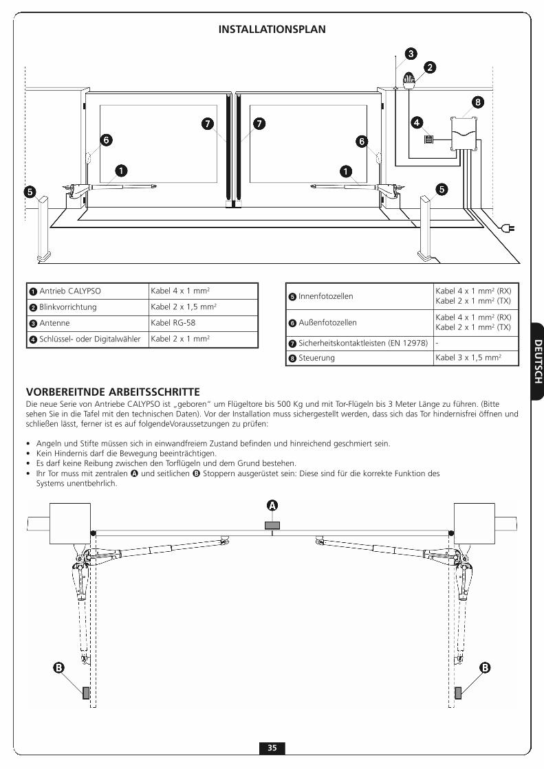
INSTALLATIONSPLAN
VORBEREITNDE ARBEITSSCHRITTEDie neue Serie von Antriebe CALYPSO ist „geboren“ um Flügeltore bis 500 Kg und mit Tor-Flügeln bis 3 Meter Länge zu führen. (Bittesehen Sie in die Tafel mit den technischen Daten). Vor der Installation muss sichergestellt werden, dass sich das Tor hindernisfrei öffnen undschließen lässt, ferner ist es auf folgendeVoraussetzungen zu prüfen:
• Angeln und Stifte müssen sich in einwandfreiem Zustand befinden und hinreichend geschmiert sein.• Kein Hindernis darf die Bewegung beeinträchtigen.• Es darf keine Reibung zwischen den Torflügeln und dem Grund bestehen.• Ihr Tor muss mit zentralen � und seitlichen � Stoppern ausgerüstet sein: Diese sind für die korrekte Funktion des Systems unentbehrlich.
� Antrieb CALYPSO Kabel 4 x 1 mm2
� Blinkvorrichtung Kabel 2 x 1,5 mm2
� Antenne Kabel RG-58
� Schlüssel- oder Digitalwähler Kabel 2 x 1 mm2
� InnenfotozellenKabel 4 x 1 mm2 (RX)Kabel 2 x 1 mm2 (TX)
� AußenfotozellenKabel 4 x 1 mm2 (RX)Kabel 2 x 1 mm2 (TX)
� Sicherheitskontaktleisten (EN 12978) -
� Steuerung Kabel 3 x 1,5 mm2

DEU
TSC
H
CALYPSO 400 (CA43, CA43M)
γ A [mm] B [mm] C [mm] F [mm]
90°
20 130 130 101040 150 140 100060 170 150 99080 190 150 980100 200 150 980120 210 140 980140 250 120 1010
100°
20 130 170 97040 150 180 96060 170 180 96080 190 170 970100 210 140 990
110°20 130 190 95040 150 180 96050 160 170 970
CALYPSO 500 (CA53, CA53M)
γ A [mm] B [mm] C [mm] F [mm]
90°
20 130 170 120040 150 180 119060 170 180 119080 190 190 1180100 210 190 1170120 230 190 1170140 250 180 1170160 270 190 1170180 290 170 1180
100°
20 130 160 121040 150 170 120060 170 170 120080 200 180 1190100 210 170 1190120 230 190 1170140 250 180 1180160 270 160 1200170 280 160 1200
110°
20 130 170 120040 150 180 119060 170 180 119080 190 190 1180100 210 200 1170110 220 200 1170
ÖFFNUNG NACH INNEN
INSTALLATIONUm eine korrekte Installation der Operatoren zu gewährleisten und ein optimales Funktionieren der Automatik zu garantieren, müssen diein der untenstehenden Tabelle aufgeführten Höhenangaben genau beachtet werden. Es könnte sich eventuell als notwendig erweisen, dieTorstruktur zu verändern, um sie an eine der hier aufgeführten Konstellationen anzupassen.
m ACHTUNG: Ab Flügelmaß von 2 Metern muß ein elektrisches Schloß zur Gewährleistung einer wirkungsvollen Scließung angebracht werden.
36

DEU
TSCH
37
ÖFFNUNG NACH AUßEN
CALYPSO 400 (CA43, CA43M)
γ A [mm] B [mm] C [mm] F [mm]
80° 30 110 ÷ 130 90 949
85° 30 110 ÷ 130 100 967
90° 30 110 ÷ 130 110 986
95° 30 110 ÷ 130 120 1006
100° 30 110 ÷ 130 130 1027
110° 30 110 ÷ 130 140 1057
CALYPSO 500 (CA53, CA53M)
γ A [mm] B [mm] C [mm] F [mm]
80° 30 130 100 995
85° 30 130 110 1005
90° 30 130 120 1015
95° 30 130 130 1025
100° 30 130 140 1035
110° 30 130 150 1045

DEU
TSC
H
38
BEFESTIGUNG DER ANTRIEBEWählen Sie die passenden Maße in der Tafel (Seite Nr.5) undzeichnen Sie die gewählten Maße auf den Pfeiler und gehendann wie folgt weiter:
• Schweißen Sie die Bügel direkt an den Pilastern und am Tor an. Wenn die Materialen keine Schweißung ermöglichen, schweißen Sie die Bügel an Platten an und dann befestigen Sie diese Platten mit Dübeln oder Schrauben am Tor und an den Pilastern.
• Schließen Sie den Flügel.• Geben Sie die Antriebe frei.• Positionieren Sie CALYPSO auf die Stützen und befestigen Sie die Stifte Nr.1 und Nr.2 mit den entsprechenden Sicherungsmuttern (bitte sehen Sie die Abbildung).
• Öffnen und schließen Sie mehrmals von Hand die Flügel und prüfen Sie, dass es keine Reibung zwischen dem Antrieb und dem Tor gibt.
m ACHTUNG: um dem Antrieb keine Schäden zuzufügen, ist es nötig, die folgende Bedienungen zuachten:
• Die Bügel müssen an der gleichen Höhe installiert werden.
• Wenn das Tor völlig geschlossen ist, der maximale Lauf des Arms A kann nicht mehr als 456 mm für CALYPSO400 (CA43, CA43M) und 556 für CALYPSO500 (CA53, CA53M) sein.
• Wen das Tor völlig geöffnet ist, der minimale Lauf des Arms B muss mindestens 56 mm sein.

DEU
TSCH
39
VERBINDUNG VON CALYPSO MIT DER STEUERUNG
m ACHTUNG: bitte verbinden Sie immer das Erdungskabel, gemäß den geltenden Bestimmungen (EN 60335-1, EN 60204-1).
Vermeiden Sie während der Öffnungs- und Schließoperationen Spannungen am Motorkabel
8μF - CA43, CA5325μF - CA43M, CA53M
8μF - CA43, CA5325μF - CA43M, CA53M
CA43, CA53 CA43M, CA53M FUNCIÓN
� GELB - GRÜN GRÜN GND
� GRAU WEISS GEMEINSAM
� SCHWARZ SCHWARZ SCHLIEßEN
� BRAUN ROT ÖFFNUNG

DEU
TSC
H
40
MOTORFREIGABE Im Fall der Unterbrechung der Stromversorgungkann das Tor über den Motor mechanischfreigegeben werden. Führen Sie denmitgelieferten Schlüssel ein, machen Sie halbeUmdrehung. Um die Betriebsbereitschaft derAutomatik wieder herzustellen, ist esausreichend, den Schlüssel in dieAnfangsposition zurück zu drehen und dieKunststoffkappe wieder über das Schloss zuschieben.