Beckman Coulter Avanti J-26-XPI User Manual - BME Shared Lab
86
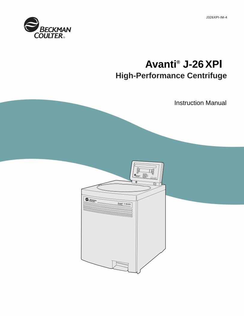
J326XPI-IM-4 Avanti ® J-26 XPI Instruction Manual High-Performance Centrifuge
Transcript of Beckman Coulter Avanti J-26-XPI User Manual - BME Shared Lab
J326XPI-IM-4
Avanti® J-26 XPI
Instruction Manual
High-Performance Centrifuge
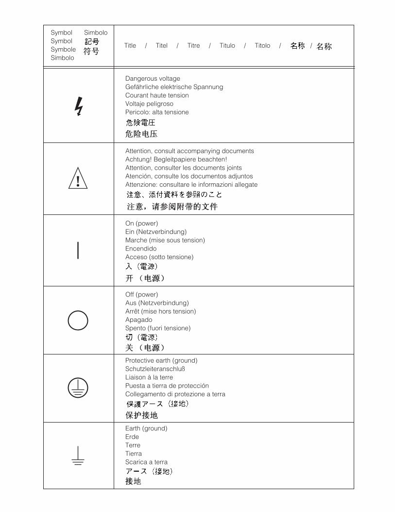
SymbolSymbolSymboleSímbolo
Title / Titel / Titre / Titulo / Titolo /
Dangerous voltageGefährliche elektrische SpannungCourant haute tensionVoltaje peligrosoPericolo: alta tensione
Attention, consult accompanying documentsAchtung! Begleitpapiere beachten!Attention, consulter les documents jointsAtención, consulte los documentos adjuntosAttenzione: consultare le informazioni allegate
On (power)Ein (Netzverbindung)Marche (mise sous tension)EncendidoAcceso (sotto tensione)
Off (power)Aus (Netzverbindung)Arrêt (mise hors tension)ApagadoSpento (fuori tensione)
Protective earth (ground)SchutzleiteranschlußLiaison à la terrePuesta a tierra de protecciónCollegamento di protezione a terra
Earth (ground)ErdeTerreTierraScarica a terra
!
/
Simbolo
SAFETY NOTICE
This safety notice summarizes information basic to the safe operation of the equipment described in this manual. The international symbol displayed above is a reminder that all safety instructions should be read and understood before installation, operation, mainte-nance, or repair of this instrument. When you see the symbol on other pages, pay special attention to the safety information presented. Observance of safety precautions will also help to avoid actions that could damage or adversely affect the performance of the centrifuge.
Safety During Installation and/or Maintenance
This centrifuge is designed to be installed by a Beckman Coulter field service representa-tive. Installation by anyone other than authorized Beckman Coulter personnel invalidates any warranty covering the instrument.
Any servicing of this equipment that requires removal of any covers can expose parts that involve the risk of electric shock or personal injury. Make sure that the power switch is turned off and the instrument is disconnected from the main power source, and refer such servicing to qualified personnel.
Be sure to use the anchoring system to secure the centrifuge in place. The anchoring system is designed to reduce the possibility of injury or damage that could result from instrument movement in the event of a major rotor mishap.
Do not replace any centrifuge components with parts not specified for use on this instrument.
Electrical Safety
To reduce the risk of electrical shock, this equipment uses a three or five-wire electrical cord and plug to connect this equipment to earth-ground. To preserve this safety feature:
• Make sure that the matching wall outlet receptacle is properly wired and earth-grounded. Check that the line voltage agrees with the voltage listed on the name-rating plate affixed to the centrifuge.
• Never use a three-to-two wire plug adapter.
• Never use a two-wire extension cord or a two-wire non-grounding type of multiple-outlet receptacle strip.
Do not place containers holding liquid on or near the chamber door. If they spill, liquid may get into the centrifuge and damage electrical or mechanical components.
Safety Against Risk of Fire
This centrifuge is not designed for use with materials capable of developing flammable or explosive vapors. Do not centrifuge such materials (for example, chloroform or ethyl alcohol) in this instrument nor handle or store them near the centrifuge.
!
Mechanical Safety
For safe operation of the equipment, observe the following:
• Use only the Beckman Coulter rotors and accessories designed for use in this centrifuge.
• Do not exceed the maximum rated speed of the rotor in use.
• NEVER attempt to slow or stop a rotor by hand.
• Do not lift or move the centrifuge while a rotor is spinning.
• NEVER attempt to override the door interlock system while the rotor is spinning.
• Do not lean on the centrifuge or place items on it while it is operating.
Chemical and Biological Safety
Normal operation may involve the use of solutions and test samples that are pathogenic, toxic, or radioactive. Such materials should not be used in this centrifuge, however, unless all necessary safety precautions are taken.
• Observe all cautionary information printed on the original solution containers prior to their use.
• Handle body fluids with care because they can transmit disease. No known test offers complete assurance that they are free of micro-organisms. Some of the most virulent—Hepatitis (B and C) and HIV (I–V) viruses, atypical mycobacteria, and certain systemic fungi—further emphasize the need for aerosol protection. Handle other infectious sam-ples according to good laboratory procedures and methods to prevent spread of disease. Because spills may generate aerosols, observe proper safety precautions for aerosol containment. Do not run toxic, pathogenic, or radioactive materials in this centrifuge without taking appropriate safety precautions. Biosafe containment should be used when Risk Group II materials (as identified in the World Health Organization Labora-tory Biosafety Manual) are handled; materials of a higher group require more than one level of protection.
• Dispose of all waste solutions according to appropriate environmental health and safety guidelines.
It is your responsibility to decontaminate the instrument and accessories before requesting service by Beckman Coulter.
J326XPI-IM-4 July 2009
Avanti® J-26 XPI
Instruction Manual
High-Performance Centrifuge
MADE IN U.S.A.
© 2009 Beckman Coulter, Inc.


Contents
Page
INTRODUCTION
Certification . . . . . . . . . . . . . . . . . . . . . . . . . . . . . . . . . . . . . . . . . . . . . viiScope of this Manual . . . . . . . . . . . . . . . . . . . . . . . . . . . . . . . . . . . . . . viiConventions . . . . . . . . . . . . . . . . . . . . . . . . . . . . . . . . . . . . . . . . . . . . . viii
Notes, Cautions, and Warnings . . . . . . . . . . . . . . . . . . . . . . . . . . . viiiTypographic Conventions . . . . . . . . . . . . . . . . . . . . . . . . . . . . . . . . ix
Radio Interference . . . . . . . . . . . . . . . . . . . . . . . . . . . . . . . . . . . . . . . . . ixCanadian Regulations . . . . . . . . . . . . . . . . . . . . . . . . . . . . . . . . . . . x
Recycling Label . . . . . . . . . . . . . . . . . . . . . . . . . . . . . . . . . . . . . . . . . . . x
SECTION 1: SPECIFICATIONS AND PREINSTALLATION REQUIREMENTS
Specifications . . . . . . . . . . . . . . . . . . . . . . . . . . . . . . . . . . . . . . . . . . . . 1-1Control Features. . . . . . . . . . . . . . . . . . . . . . . . . . . . . . . . . . . . . . . 1-1Operational Features . . . . . . . . . . . . . . . . . . . . . . . . . . . . . . . . . . . 1-2Physical Data . . . . . . . . . . . . . . . . . . . . . . . . . . . . . . . . . . . . . . . . . 1-2
Available Rotors. . . . . . . . . . . . . . . . . . . . . . . . . . . . . . . . . . . . . . . . . . 1-3Preinstallation Requirements . . . . . . . . . . . . . . . . . . . . . . . . . . . . . . . . 1-8
Electrical Requirements. . . . . . . . . . . . . . . . . . . . . . . . . . . . . . . . . 1-8Space and Location Requirements. . . . . . . . . . . . . . . . . . . . . . . . 1-11Securing the Centrifuge to the Floor . . . . . . . . . . . . . . . . . . . . . . 1-13Bio-Safety Level 3 Installation . . . . . . . . . . . . . . . . . . . . . . . . . . 1-13
Using J2 Series Rotors in the Avanti J . . . . . . . . . . . . . . . . . . . . . . . . 1-14Checking for Rotor Drive Pins . . . . . . . . . . . . . . . . . . . . . . . . . . 1-14Using the JA-18 Rotor . . . . . . . . . . . . . . . . . . . . . . . . . . . . . . . . . 1-14Using the JCF-Z Continuous Flow/Zonal Rotor . . . . . . . . . . . . . 1-15
iii
iv
Contents
Page
SECTION 2: DESCRIPTION
Centrifuge Function and Safety Features . . . . . . . . . . . . . . . . . . . . . . . 2-1Centrifuge Function . . . . . . . . . . . . . . . . . . . . . . . . . . . . . . . . . . . . 2-1Safety Features. . . . . . . . . . . . . . . . . . . . . . . . . . . . . . . . . . . . . . . . 2-2Housing and Door . . . . . . . . . . . . . . . . . . . . . . . . . . . . . . . . . . . . . 2-3Rotor Chamber. . . . . . . . . . . . . . . . . . . . . . . . . . . . . . . . . . . . . . . . 2-3Drive . . . . . . . . . . . . . . . . . . . . . . . . . . . . . . . . . . . . . . . . . . . . . . . 2-3Friction Reduction System (FRS) . . . . . . . . . . . . . . . . . . . . . . . . . 2-4Temperature Sensing and Control . . . . . . . . . . . . . . . . . . . . . . . . . 2-4Overtemp System. . . . . . . . . . . . . . . . . . . . . . . . . . . . . . . . . . . . . . 2-4
Name Rating Plate . . . . . . . . . . . . . . . . . . . . . . . . . . . . . . . . . . . . . . . . 2-5
Controls and Indicators . . . . . . . . . . . . . . . . . . . . . . . . . . . . . . . . . . . . 2-5Key and Power Switches . . . . . . . . . . . . . . . . . . . . . . . . . . . . . . . . 2-5Control Panel . . . . . . . . . . . . . . . . . . . . . . . . . . . . . . . . . . . . . . . . . 2-6Keypad. . . . . . . . . . . . . . . . . . . . . . . . . . . . . . . . . . . . . . . . . . . . . 2-10System Keys . . . . . . . . . . . . . . . . . . . . . . . . . . . . . . . . . . . . . . . . 2-10
SECTION 3: OPERATION
Summary of Avanti J-26XPI Run Procedures . . . . . . . . . . . . . . . . . . . 3-2Manual Run . . . . . . . . . . . . . . . . . . . . . . . . . . . . . . . . . . . . . . . . . . 3-2Programmed Run . . . . . . . . . . . . . . . . . . . . . . . . . . . . . . . . . . . . . . 3-3
Preparation . . . . . . . . . . . . . . . . . . . . . . . . . . . . . . . . . . . . . . . . . . . . . . 3-3Installing the Rotor . . . . . . . . . . . . . . . . . . . . . . . . . . . . . . . . . . . . 3-3
Manual Operation. . . . . . . . . . . . . . . . . . . . . . . . . . . . . . . . . . . . . . . . . 3-4Selecting a Rotor . . . . . . . . . . . . . . . . . . . . . . . . . . . . . . . . . . . . . . 3-5Entering Run Speed . . . . . . . . . . . . . . . . . . . . . . . . . . . . . . . . . . . . 3-5Entering Run Time . . . . . . . . . . . . . . . . . . . . . . . . . . . . . . . . . . . . 3-7Entering Run Temperature . . . . . . . . . . . . . . . . . . . . . . . . . . . . . 3-10Entering Acceleration and Deceleration Rates . . . . . . . . . . . . . . 3-11Starting a Run . . . . . . . . . . . . . . . . . . . . . . . . . . . . . . . . . . . . . . . 3-13Changing Parameters During a Run . . . . . . . . . . . . . . . . . . . . . . 3-13Ending a Run . . . . . . . . . . . . . . . . . . . . . . . . . . . . . . . . . . . . . . . . 3-14

Contents
Page
Programmed Operation . . . . . . . . . . . . . . . . . . . . . . . . . . . . . . . . . . . 3-14Creating a New Program . . . . . . . . . . . . . . . . . . . . . . . . . . . . . . . 3-14Modifying a Program. . . . . . . . . . . . . . . . . . . . . . . . . . . . . . . . . . 3-16Running a Program . . . . . . . . . . . . . . . . . . . . . . . . . . . . . . . . . . . 3-18
Setting Up a Zonal Run . . . . . . . . . . . . . . . . . . . . . . . . . . . . . . . . . . . 3-18Setting Up an Elutriation Run . . . . . . . . . . . . . . . . . . . . . . . . . . . . . . 3-20
SECTION 4: TROUBLESHOOTING
User Messages . . . . . . . . . . . . . . . . . . . . . . . . . . . . . . . . . . . . . . . . . . . 4-1Accessing the Rotor in Case of Power Failure. . . . . . . . . . . . . . . . . . . 4-5JCF-Z Rotor Identification . . . . . . . . . . . . . . . . . . . . . . . . . . . . . . . . . 4-11
SECTION 5: CARE AND MAINTENANCE
Maintenance . . . . . . . . . . . . . . . . . . . . . . . . . . . . . . . . . . . . . . . . . . . . . 5-2Cleaning. . . . . . . . . . . . . . . . . . . . . . . . . . . . . . . . . . . . . . . . . . . . . 5-2Decontamination . . . . . . . . . . . . . . . . . . . . . . . . . . . . . . . . . . . . . . 5-3Sterilization and Disinfection . . . . . . . . . . . . . . . . . . . . . . . . . . . . 5-3Replacing the Air Filter . . . . . . . . . . . . . . . . . . . . . . . . . . . . . . . . . 5-4
Circuit Breaker and Fuses . . . . . . . . . . . . . . . . . . . . . . . . . . . . . . . . . . 5-4Storage and Transport . . . . . . . . . . . . . . . . . . . . . . . . . . . . . . . . . . . . . 5-4
Storage . . . . . . . . . . . . . . . . . . . . . . . . . . . . . . . . . . . . . . . . . . . . . . 5-4Returning a Centrifuge . . . . . . . . . . . . . . . . . . . . . . . . . . . . . . . . . 5-5
Supply List . . . . . . . . . . . . . . . . . . . . . . . . . . . . . . . . . . . . . . . . . . . . . . 5-5Replacement Parts and Supplies . . . . . . . . . . . . . . . . . . . . . . . . . . 5-5
APPENDIX: TEMPERATURE CALIBRATION PROCEDURE
WARRANTY
v
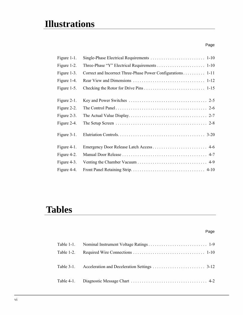
Illustrations
vi
Ta
Page
Figure 1-1. Single-Phase Electrical Requirements . . . . . . . . . . . . . . . . . . . . . . . . . 1-10
Figure 1-2. Three-Phase “Y” Electrical Requirements . . . . . . . . . . . . . . . . . . . . . . 1-10
Figure 1-3. Correct and Incorrect Three-Phase Power Configurations . . . . . . . . . . 1-11
Figure 1-4. Rear View and Dimensions . . . . . . . . . . . . . . . . . . . . . . . . . . . . . . . . . 1-12
Figure 1-5. Checking the Rotor for Drive Pins . . . . . . . . . . . . . . . . . . . . . . . . . . . . 1-15
Figure 2-1. Key and Power Switches . . . . . . . . . . . . . . . . . . . . . . . . . . . . . . . . . . . . 2-5
Figure 2-2. The Control Panel . . . . . . . . . . . . . . . . . . . . . . . . . . . . . . . . . . . . . . . . . . 2-6
Figure 2-3. The Actual Value Display. . . . . . . . . . . . . . . . . . . . . . . . . . . . . . . . . . . . 2-7
Figure 2-4. The Setup Screen . . . . . . . . . . . . . . . . . . . . . . . . . . . . . . . . . . . . . . . . . . 2-8
Figure 3-1. Elutriation Controls. . . . . . . . . . . . . . . . . . . . . . . . . . . . . . . . . . . . . . . . 3-20
Figure 4-1. Emergency Door Release Latch Access . . . . . . . . . . . . . . . . . . . . . . . . . 4-6
Figure 4-2. Manual Door Release . . . . . . . . . . . . . . . . . . . . . . . . . . . . . . . . . . . . . . . 4-7
Figure 4-3. Venting the Chamber Vacuum . . . . . . . . . . . . . . . . . . . . . . . . . . . . . . . . 4-9
Figure 4-4. Front Panel Retaining Strip. . . . . . . . . . . . . . . . . . . . . . . . . . . . . . . . . . 4-10
bles
Page
Table 1-1. Nominal Instrument Voltage Ratings . . . . . . . . . . . . . . . . . . . . . . . . . . . 1-9
Table 1-2. Required Wire Connections . . . . . . . . . . . . . . . . . . . . . . . . . . . . . . . . . 1-10
Table 3-1. Acceleration and Deceleration Settings . . . . . . . . . . . . . . . . . . . . . . . . 3-12
Table 4-1. Diagnostic Message Chart . . . . . . . . . . . . . . . . . . . . . . . . . . . . . . . . . . . 4-2
Introduction
CERTIFICATION
To ensure full system quality, Beckman Coulter Avanti® J-26XPI centrifuges are manufactured in a registered ISO 9001 or 13485 facility. They have been designed and tested to be compliant (when used with Beckman Coulter rotors) with the laboratory equipment requirements of applicable regulatory agencies. Declarations of conformity and certificates of compliance are available at www.beckmancoulter.com.
SCOPE OF THIS MANUAL
This manual is designed to familiarize you with the Avanti® J-26XPI centrifuge, its functions, specifications, operation, and routine opera-tor care and maintenance. We recommend that you read this entire manual, especially the SAFETY NOTICE and all safety-related infor-mation, before operating the instrument or performing instrument maintenance.
• Section 1 contains system specifications and instructions for preparing your site for installation of the centrifuge.
• Section 2 contains an overall description of the centrifuge, including a description of system controls and indicators.
• Section 3 summarizes procedures for operating the centrifuge.
• Section 4 lists possible error messages and/or malfunctions, together with probable causes and required corrective actions.
• Section 5 contains procedures for routine maintenance, as well as a brief list of supplies and replacement parts.
vii
viii
Introduction
• The Appendix contains a procedure to use when temperature control within ±1°C is required.
➠ NOTEIf the centrifuge is used in a manner other than specified in this manual, the safety and perfor-mance of this equipment could be impaired. Further, the use of any equipment other than that recommended by Beckman Coulter has not been evaluated for safety. Use of any equipment not specifically recommended in this manual is the sole responsibility of the user.
CONVENTIONS
Certain symbols are used in this manual to call out safety-related and other important information. These international symbols may also be displayed on the centrifuge and are reproduced and described below and on the inside of the front cover.
NOTES, CAUTIONS, AND WARNINGS
➠ NOTEUsed to call attention to information that should be followed during installation, use, and/or servicing of the equipment.
! CAUTIONUsed to indicate a potentially hazardous situa-tion which, if not avoided, may result in minor or moderate injury and/or mechanical damage. It is also used to alert against unsafe practices.
Introduction
! WARNINGUsed whenever an action or condition may potentially cause personal injury or loss of life. Mechanical damage may also result.
WARNINGIndicates high voltage or risk of electric shock. Refer servicing of all areas displaying either symbol to qualified service personnel.
TYPOGRAPHIC CONVENTIONS
Certain typographic conventions are used throughout this manual to distinguish names of user interface components, such as keys and displays.
• Key names (for example, [START] and [STOP]) appear in capital letters within brackets.
• Actual value display names and setup screen field names (for example, TEMP°C and Rotor:) appear in bold type.
RADIO INTERFERENCE
This instrument has been tested and found to comply with the limits for a Class A digital device, pursuant to Part 15 of FCC Rules. These limits are designed to provide reasonable protection against harmful interference when the equipment is operated in a commercial environment. This equipment generates, uses, and can radiate radio frequency energy and, if not installed and used in accordance with this instruction manual, may cause interference to radio communica-tions. Operation of this equipment in a residential area may cause interference, in which case the user will be required to correct the interference at his own expense.
ix
x
Introduction
CANADIAN REGULATIONS
This digital apparatus does not exceed the Class A limits for radio noise emissions from digital apparatus as set out in the radio interfer-ence regulations of the Canadian Department of Communications.
Le présent appareil numérique n’émet pas de bruits radioélectriques dépassant les limites applicables aux appareils numériques de Classe A prescrites dans le reglement sur le brouillage radioelectrique édicté par le Ministère des Communications du Canada.
RECYCLING LABEL
This symbol is required in accordance with the Waste Electrical and Electronic Equipment (WEEE) Directive of the European Union. The presence of this marking on the product indicates:
1) the device was put on the European market after August 13, 2005 and
2) the device is not to be disposed via the municipal waste collection system of any member state of the European Union.
It is very important that customers understand and follow all laws regarding the proper decontamination and safe disposal of electrical equipment. For Beckman Coulter products bearing this label please contact your dealer or local Beckman Coulter office for details on the take back program that will facilitate the proper collection, treatment, recovery, recycling and safe disposal of the device.
A28219-AA
Note: On the instrument, the triangle background is yellow rather than gray.
1Specifications and
Preinstallation Requirements
SPECIFICATIONSOnly values with tolerances or limits are guaranteed data. Values without tolerances are informative data, without guarantee.
CONTROL FEATURES
SpeedSetting range. . . . . . . . . . . . 100 to 26 000 rpm (in 10-rpm increments)
or equivalent RCF (in 100 × g increments)Elutriation speed setting range . . . . . . . . . . . 0 to 5 000 rpm (in 10-rpm
or 10 × g increments)Speed display . . . . . . . . . . . . . . . . . . . . from 0 to 10 000 rpm, indicates actual
rotor speed ±10 rpmfrom 10 000 to 26 000 rpm, indicates actual
rotor speed ±0.1%, or equivalent RCFTime
Setting range. . . . . . . 1 min to 99 hr 59 min, ω2t, or continuous (hold)Actual display. . . . . . . . . . . . indicates run time remaining (timed run),
ω2t, or elapsed time (hold run)ω2t setting range . . . . . . up to 9.99 × 10¹⁴ radians squared per secondω2t actual display. . . . . . . . indicates accumulated centrifugal effect to
3 significant digits (in exponential notation)Temperature
Setting range. . . . . . . . . . . . . . . . . . –10 to +40°C (in 1°C increments)Accuracy. . . . . . . . . . . . . . . . . . . rotor temperature controlled to within
±2°C of set temperature (after equilibration)*Ambient temperature range . . . . . . . . . . . . . 16 to 38°C (60 to 100°F)†
Cooling fluid. . . . . . . . . . . . . . . . . . . . . . . . . . Refrigerant 404A (HFC)Acceleration. . . . . . . . . . . . . . . . . . . . . . . . . . . . . .maximum, slow, or timed
(1 to 10 min from 0 to 500 rpm)
_______________* During transient conditions, such as acceleration and deceleration, rotor temperature may be outside this range. Refer to applicable rotor manuals
for specific rotor operating range information.† To reach temperatures above ambient, the centrifuge is dependent on the frictional heat generated inside the chamber during operation. At low
run speeds or low ambient temperatures, the centrifuge may not be able to achieve some higher temperatures.
CFC
1-1

1-2
Specifications and Preinstallation Requirements
Deceleration . . . . . . . . . . . . . . . . . . . . . . . . . . . . . . . maximum, slow, timed (1 to 10 min from 500 to 0 rpm), or off
OPERATIONAL FEATURES
Door. . . . . . . . . . . . . . . . . . . . . . . . . . . . . . 6.1-cm (2.4-in.) thick structural foam with steel plate
Rotor chamber diameter . . . . . . . . . . . . . . . . . . . . . . . . . . . 51.3 cm (20 in.)Friction Reduction System (FRS) . . . . . . . . . . . . . . . . . 190 mm (7.5 in.) Hg
PHYSICAL DATA
Width . . . . . . . . . . . . . . . . . . . . . . . . . . . . . . . . . . . . . . . . . . . . 71 cm (28 in.)Depth . . . . . . . . . . . . . . . . . . . . . . . . . . . . . . . . . . . . . . . . . . . . 86 cm (34 in.)Depth (including air diverter extending
from back panel) . . . . . . . . . . . . . . . . . . . . . . . . . . . 102 cm (40.25 in.)Height, door closed . . . . . . . . . . . . . . . . . . . . . . . . . . . . . . . . . 86 cm (34 in.)Height to top of control head. . . . . . . . . . . . . . . . . . . . . . . 116 cm (45.5 in.)Height to top of open door . . . . . . . . . . . . . . . . . . . . . . . . 149 cm (58.5 in.)Weight . . . . . . . . . . . . . . . . . . . . . . . . . . . . . . . . . . . . . . . . . 290 kg (640 lb)Clearances (for adequate ventilation)
Sides . . . . . . . . . . . . . . . . . . . . . . . . . . . . . . . . . . . . . . . . . 7.6 cm (3 in.)Back (place air diverter against the wall). . . . . . . . . . . 16 cm (6.25 in.)
Surface finish. . . . . . . . . . . . . . . polyester control panel with polycarbonate coating overlay; polyurethane enamel on door and covers;
acrylic baking enamel on other surfacesMaximum heat dissipation into room
under steady-state conditions . . . . . . . . . . . . . . . . 6900 Btu/h (2.0 kW)Humidity restrictions. . . . . . . . . . . . . . . . . . . . . . . . <95% (noncondensing)Noise level 0.91 m (3 ft) in front of instrument
at 26 000 rpm . . . . . . . . . . . . . . . . . . . . . . . . . . . . . . . . . . . . . . 57 dBaElectrical requirements
200/208/240-V, single-phase instrument. . . . . . . . . . . . . . 180–264 VAC, 30 A, 50/60 Hz
230-V, single-phase instrument . . . . . . . . . . . 180–264 VAC, 30 A, 50 Hz220/380-V plus neutral, three-phase*
instrument. . . . . . . . . . . . . . . . . . . . . . . . . 313–457 VAC plus neutral, 16 A, 50 Hz
Electrical supply . . . . . . . . . . . . . . . . . . . . . . . . . . . . . . . . . . . . . . . . Class IInstallation (overvoltage) category . . . . . . . . . . . . . . . . . . . . . . . . . . . . . . IIPollution degree. . . . . . . . . . . . . . . . . . . . . . . . . . . . . . . . . . . . . . . . . . . . . 2†
__________________* Unbalanced three-phase. Split for single-phase operation internally.† Normally only nonconductive pollution occurs; occasionally, however, a temporary conductivity caused by condensation must be expected.
Specifications and Preinstallation Requirements
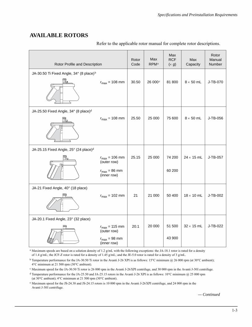
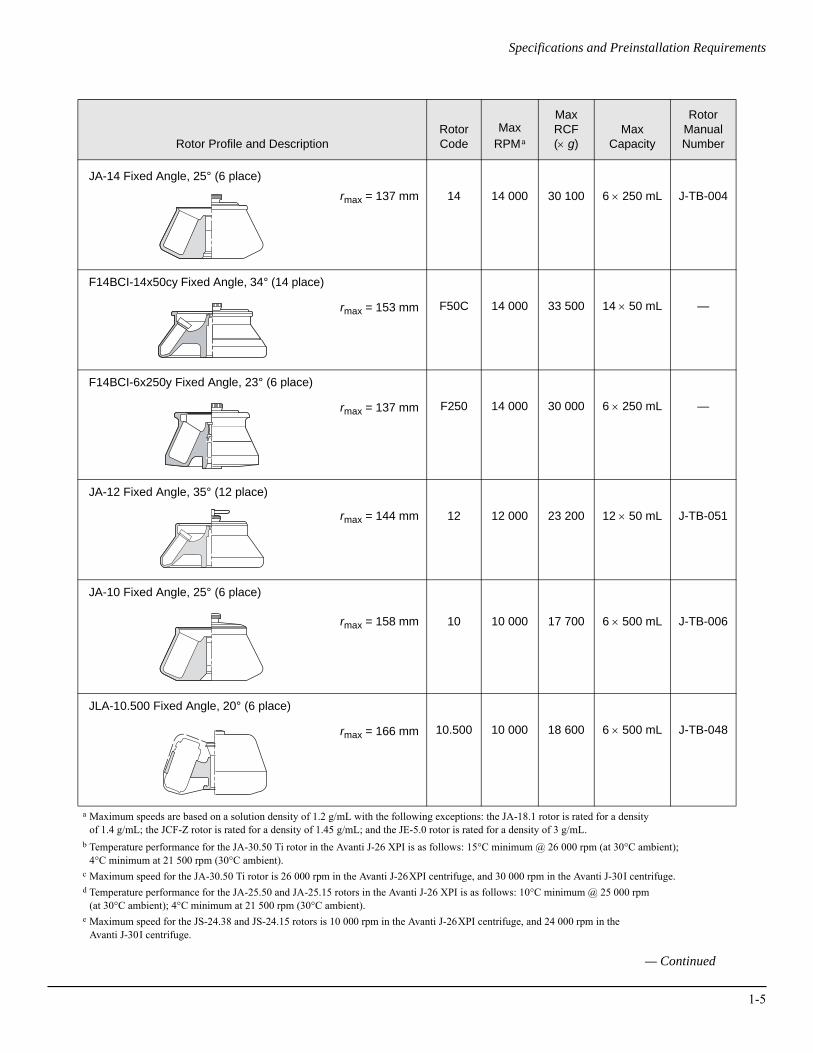
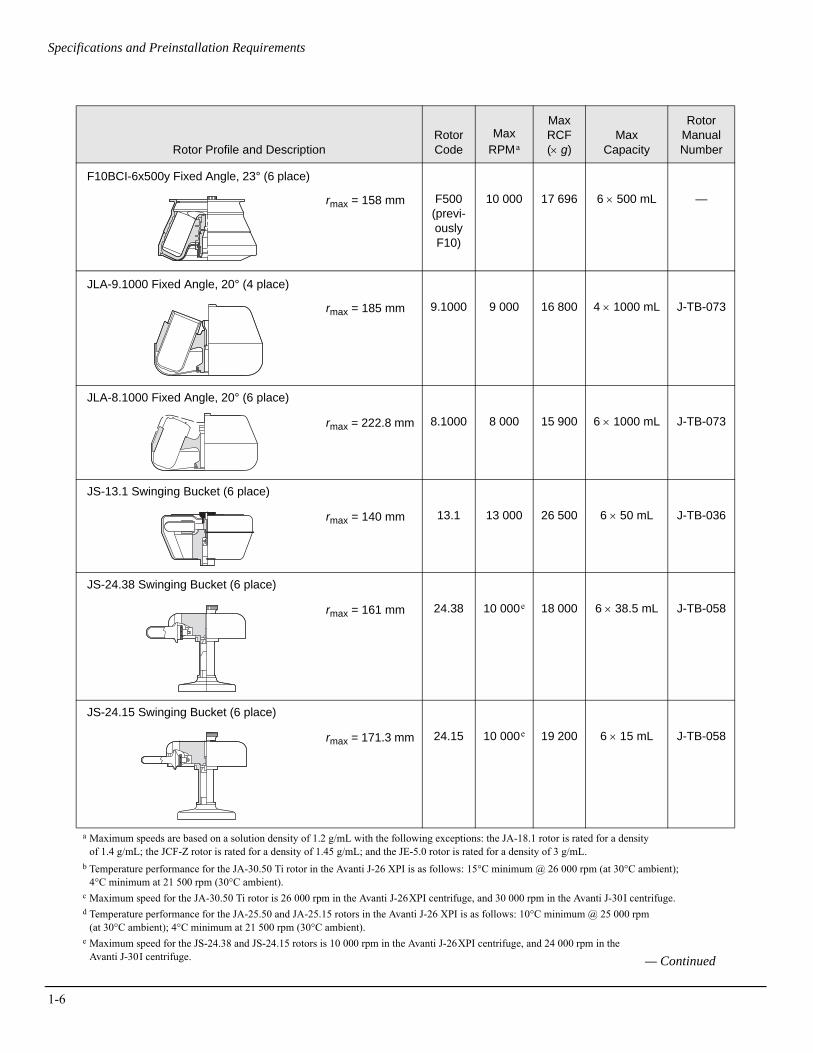
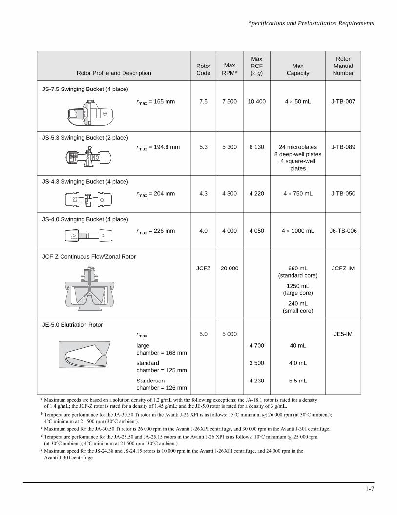
AVAILABLE ROTORSRefer to the applicable rotor manual for complete rotor descriptions.
a Maximum speeds are based on a solution density of 1.2 g/mL with the following exceptions: the JA-18.1 rotor is rated for a density of 1.4 g/mL; the JCF-Z rotor is rated for a density of 1.45 g/mL; and the JE-5.0 rotor is rated for a density of 3 g/mL.
b Temperature performance for the JA-30.50 Ti rotor in the Avanti J-26 XPI is as follows: 15°C minimum @ 26 000 rpm (at 30°C ambient); 4°C minimum at 21 500 rpm (30°C ambient).
c Maximum speed for the JA-30.50 Ti rotor is 26 000 rpm in the Avanti J-26XPI centrifuge, and 30 000 rpm in the Avanti J-30I centrifuge.d Temperature performance for the JA-25.50 and JA-25.15 rotors in the Avanti J-26 XPI is as follows: 10°C minimum @ 25 000 rpm
(at 30°C ambient); 4°C minimum at 21 500 rpm (30°C ambient).e Maximum speed for the JS-24.38 and JS-24.15 rotors is 10 000 rpm in the Avanti J-26XPI centrifuge, and 24 000 rpm in the
Avanti J-30I centrifuge.
Rotor Profile and DescriptionRotorCode
Max RPMa
MaxRCF(× g)
MaxCapacity
RotorManualNumber
JA-30.50 Ti Fixed Angle, 34° (8 place)b
rmax = 108 mm 30.50 26 000c 81 800 8 × 50 mL J-TB-070
JA-25.50 Fixed Angle, 34° (8 place)d
rmax = 108 mm 25.50 25 000 75 600 8 × 50 mL J-TB-056
JA-25.15 Fixed Angle, 25° (24 place)d
rmax = 106 mm(outer row)
rmax = 86 mm(inner row)
25.15 25 000 74 200
60 200
24 × 15 mL J-TB-057
JA-21 Fixed Angle, 40° (18 place)
rmax = 102 mm 21 21 000 50 400 18 × 10 mL J-TB-002
JA-20.1 Fixed Angle, 23° (32 place)
rmax = 115 mm(outer row)
rmax = 98 mm(inner row)
20.1 20 000 51 500
43 900
32 × 15 mL J-TB-022
— Continued
1-3
1-4
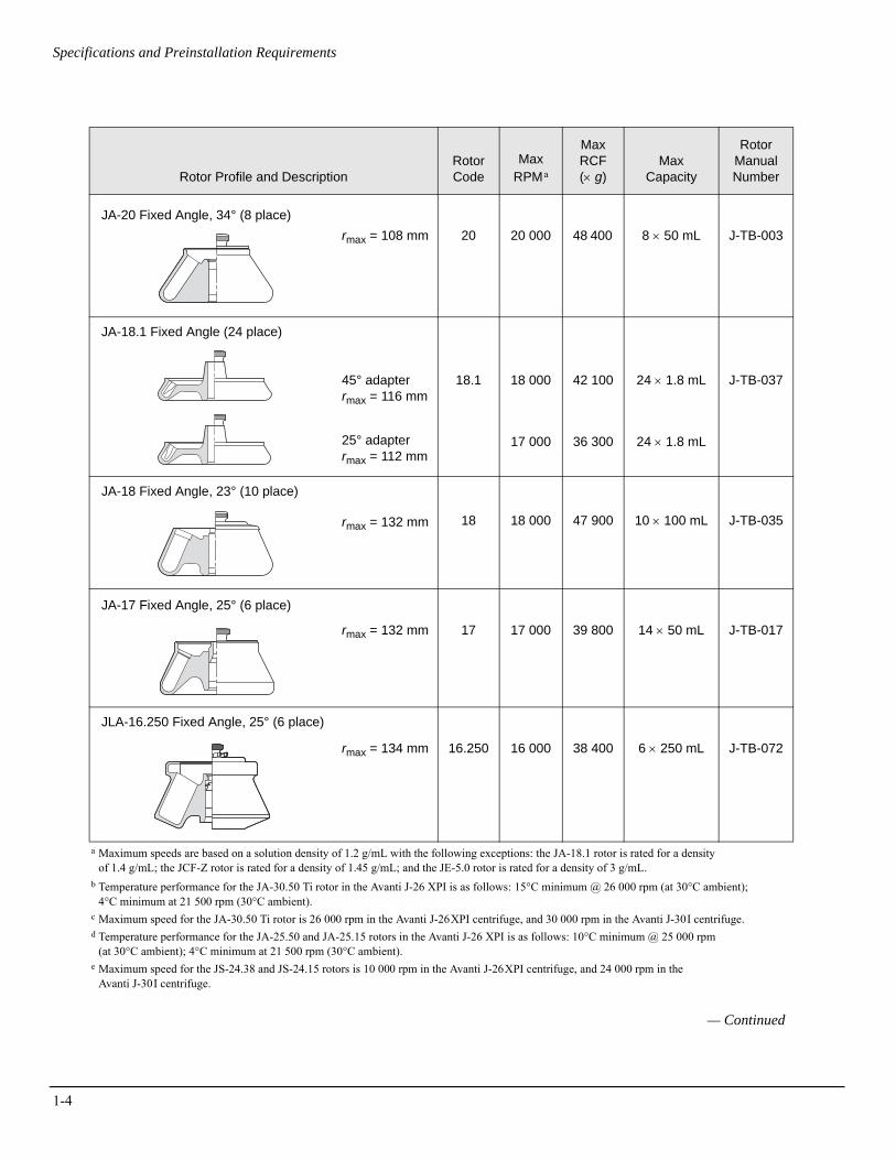
Specifications and Preinstallation Requirements
a Maximum speeds are based on a solution density of 1.2 g/mL with the following exceptions: the JA-18.1 rotor is rated for a density of 1.4 g/mL; the JCF-Z rotor is rated for a density of 1.45 g/mL; and the JE-5.0 rotor is rated for a density of 3 g/mL.
b Temperature performance for the JA-30.50 Ti rotor in the Avanti J-26 XPI is as follows: 15°C minimum @ 26 000 rpm (at 30°C ambient); 4°C minimum at 21 500 rpm (30°C ambient).
c Maximum speed for the JA-30.50 Ti rotor is 26 000 rpm in the Avanti J-26XPI centrifuge, and 30 000 rpm in the Avanti J-30I centrifuge.d Temperature performance for the JA-25.50 and JA-25.15 rotors in the Avanti J-26 XPI is as follows: 10°C minimum @ 25 000 rpm
(at 30°C ambient); 4°C minimum at 21 500 rpm (30°C ambient).e Maximum speed for the JS-24.38 and JS-24.15 rotors is 10 000 rpm in the Avanti J-26XPI centrifuge, and 24 000 rpm in the
Avanti J-30I centrifuge.
Rotor Profile and DescriptionRotorCode
Max RPMa
Max RCF(× g)
MaxCapacity
RotorManualNumber
JA-20 Fixed Angle, 34° (8 place)rmax = 108 mm 20 20 000 48 400 8 × 50 mL J-TB-003
JA-18.1 Fixed Angle (24 place)
45° adapterrmax = 116 mm
25° adapterrmax = 112 mm
18.1 18 000
17 000
42 100
36 300
24 × 1.8 mL
24 × 1.8 mL
J-TB-037
JA-18 Fixed Angle, 23° (10 place)
rmax = 132 mm 18 18 000 47 900 10 × 100 mL J-TB-035
JA-17 Fixed Angle, 25° (6 place)
rmax = 132 mm 17 17 000 39 800 14 × 50 mL J-TB-017
JLA-16.250 Fixed Angle, 25° (6 place)
rmax = 134 mm 16.250 16 000 38 400 6 × 250 mL J-TB-072
— Continued
Specifications and Preinstallation Requirements
a Maximum speeds are based on a solution density of 1.2 g/mL with the following exceptions: the JA-18.1 rotor is rated for a density of 1.4 g/mL; the JCF-Z rotor is rated for a density of 1.45 g/mL; and the JE-5.0 rotor is rated for a density of 3 g/mL.
b Temperature performance for the JA-30.50 Ti rotor in the Avanti J-26 XPI is as follows: 15°C minimum @ 26 000 rpm (at 30°C ambient); 4°C minimum at 21 500 rpm (30°C ambient).
c Maximum speed for the JA-30.50 Ti rotor is 26 000 rpm in the Avanti J-26XPI centrifuge, and 30 000 rpm in the Avanti J-30I centrifuge.d Temperature performance for the JA-25.50 and JA-25.15 rotors in the Avanti J-26 XPI is as follows: 10°C minimum @ 25 000 rpm
(at 30°C ambient); 4°C minimum at 21 500 rpm (30°C ambient).e Maximum speed for the JS-24.38 and JS-24.15 rotors is 10 000 rpm in the Avanti J-26XPI centrifuge, and 24 000 rpm in the
Avanti J-30I centrifuge.
Rotor Profile and DescriptionRotorCode
Max RPMa
Max RCF(× g)
MaxCapacity
RotorManualNumber
JA-14 Fixed Angle, 25° (6 place)
rmax = 137 mm 14 14 000 30 100 6 × 250 mL J-TB-004
F14BCI-14x50cy Fixed Angle, 34° (14 place)
rmax = 153 mm F50C 14 000 33 500 14 × 50 mL —
F14BCI-6x250y Fixed Angle, 23° (6 place)
rmax = 137 mm F250 14 000 30 000 6 × 250 mL —
JA-12 Fixed Angle, 35° (12 place)
rmax = 144 mm 12 12 000 23 200 12 × 50 mL J-TB-051
JA-10 Fixed Angle, 25° (6 place)
rmax = 158 mm 10 10 000 17 700 6 × 500 mL J-TB-006
JLA-10.500 Fixed Angle, 20° (6 place)
rmax = 166 mm 10.500 10 000 18 600 6 × 500 mL J-TB-048
— Continued
1-5
1-6
Specifications and Preinstallation Requirements
a Maximum speeds are based on a solution density of 1.2 g/mL with the following exceptions: the JA-18.1 rotor is rated for a density of 1.4 g/mL; the JCF-Z rotor is rated for a density of 1.45 g/mL; and the JE-5.0 rotor is rated for a density of 3 g/mL.
b Temperature performance for the JA-30.50 Ti rotor in the Avanti J-26 XPI is as follows: 15°C minimum @ 26 000 rpm (at 30°C ambient); 4°C minimum at 21 500 rpm (30°C ambient).
c Maximum speed for the JA-30.50 Ti rotor is 26 000 rpm in the Avanti J-26XPI centrifuge, and 30 000 rpm in the Avanti J-30I centrifuge.d Temperature performance for the JA-25.50 and JA-25.15 rotors in the Avanti J-26 XPI is as follows: 10°C minimum @ 25 000 rpm
(at 30°C ambient); 4°C minimum at 21 500 rpm (30°C ambient).e Maximum speed for the JS-24.38 and JS-24.15 rotors is 10 000 rpm in the Avanti J-26XPI centrifuge, and 24 000 rpm in the
Avanti J-30I centrifuge.
Rotor Profile and DescriptionRotorCode
Max RPMa
Max RCF(× g)
MaxCapacity
RotorManualNumber
F10BCI-6x500y Fixed Angle, 23° (6 place)
rmax = 158 mm F500(previ-ously F10)
10 000 17 696 6 × 500 mL —
JLA-9.1000 Fixed Angle, 20° (4 place)
rmax = 185 mm 9.1000 9 000 16 800 4 × 1000 mL J-TB-073
JLA-8.1000 Fixed Angle, 20° (6 place)
rmax = 222.8 mm 8.1000 8 000 15 900 6 × 1000 mL J-TB-073
JS-13.1 Swinging Bucket (6 place)
rmax = 140 mm 13.1 13 000 26 500 6 × 50 mL J-TB-036
JS-24.38 Swinging Bucket (6 place)
rmax = 161 mm 24.38 10 000e 18 000 6 × 38.5 mL J-TB-058
JS-24.15 Swinging Bucket (6 place)
rmax = 171.3 mm 24.15 10 000e 19 200 6 × 15 mL J-TB-058
— Continued
Specifications and Preinstallation Requirements
a Maximum speeds are based on a solution density of 1.2 g/mL with the following exceptions: the JA-18.1 rotor is rated for a density of 1.4 g/mL; the JCF-Z rotor is rated for a density of 1.45 g/mL; and the JE-5.0 rotor is rated for a density of 3 g/mL.
b Temperature performance for the JA-30.50 Ti rotor in the Avanti J-26 XPI is as follows: 15°C minimum @ 26 000 rpm (at 30°C ambient); 4°C minimum at 21 500 rpm (30°C ambient).
c Maximum speed for the JA-30.50 Ti rotor is 26 000 rpm in the Avanti J-26XPI centrifuge, and 30 000 rpm in the Avanti J-30I centrifuge.d Temperature performance for the JA-25.50 and JA-25.15 rotors in the Avanti J-26 XPI is as follows: 10°C minimum @ 25 000 rpm
(at 30°C ambient); 4°C minimum at 21 500 rpm (30°C ambient).e Maximum speed for the JS-24.38 and JS-24.15 rotors is 10 000 rpm in the Avanti J-26XPI centrifuge, and 24 000 rpm in the
Avanti J-30I centrifuge.
Rotor Profile and DescriptionRotorCode
Max RPMa
Max RCF(× g)
MaxCapacity
RotorManualNumber
JS-7.5 Swinging Bucket (4 place)
rmax = 165 mm 7.5 7 500 10 400 4 × 50 mL J-TB-007
JS-5.3 Swinging Bucket (2 place)rmax = 194.8 mm 5.3 5 300 6 130 24 microplates
8 deep-well plates4 square-well
plates
J-TB-089
JS-4.3 Swinging Bucket (4 place)
rmax = 204 mm 4.3 4 300 4 220 4 × 750 mL J-TB-050
JS-4.0 Swinging Bucket (4 place)
rmax = 226 mm 4.0 4 000 4 050 4 × 1000 mL J6-TB-006
JCF-Z Continuous Flow/Zonal Rotor
JCFZ 20 000 660 mL(standard core)
1250 mL(large core)
240 mL(small core)
JCFZ-IM
JE-5.0 Elutriation Rotorrmax
large chamber = 168 mm
standardchamber = 125 mm
Sandersonchamber = 126 mm
5.0 5 000
4 700
3 500
4 230
40 mL
4.0 mL
5.5 mL
JE5-IM
1-7
1-8
Specifications and Preinstallation Requirements
PREINSTALLATION REQUIREMENTS
Do not attempt to install this instrument. Its purchase price includes installation by Beckman Coulter personnel. Installation by anyone other than an authorized Beckman Coulter representative invalidates any warranty covering the instrument.
Preinstallation requirements have been sent prior to shipment of the instrument. The following information is provided in case the centri-fuge must be relocated.
The centrifuge will be installed upon initial purchase by a Beckman Coulter Field Service representative after preinstallation requirements for power and site preparation have been met. The following equip-ment is required for preinstallation:
• Voltmeter
• For single-phase centrifuges: two 30-ampere circuit breakers
• For three-phase centrifuges: three 16-ampere circuit breakers
• Power receptacle (see Figure 1-1 or 1-2)
• Drill for drilling holes in the floor for installation of anchoring kit bolts (see SECURING THE CENTRIFUGE TO THE FLOOR, later in this section). A 9.5 mm (3/8-inch) drill is required for concrete floors. A 6.4 mm (1/4-inch) drill is required for wood floors.
ELECTRICAL REQUIREMENTS
Power to the centrifuge should originate directly from a main power line transformer at a power source known to be clear of erratic loads, spikes, and electromagnetic interference. Make sure that there are properly rated thermal circuit breakers at the service panel to protect the centrifuge circuit. If fuses must be used instead of specified circuit breakers, the fuses may require a rating of greater than 30 Amperes (for single-phase centrifuges) or greater than 16 Amperes (for three-phase centrifuges).
Terminate the open end of the harmonized cord with a certified single- or three-phase connector suitable for the power supplied in the country of intended use (see Table 1-1). Install only one centrifuge per circuit.
Specifications and Preinstallation Requirements
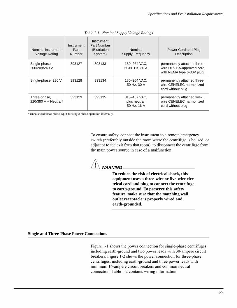
Table 1-1. Nominal Supply Voltage Ratings
* Unbalanced three-phase. Split for single-phase operation internally.
To ensure safety, connect the instrument to a remote emergency switch (preferably outside the room where the centrifuge is housed, or adjacent to the exit from that room), to disconnect the centrifuge from the main power source in case of a malfunction.
! WARNINGTo reduce the risk of electrical shock, this equipment uses a three-wire or five-wire elec-trical cord and plug to connect the centrifuge to earth-ground. To preserve this safety feature, make sure that the matching wall outlet receptacle is properly wired and earth-grounded.
Single and Three-Phase Power Connections
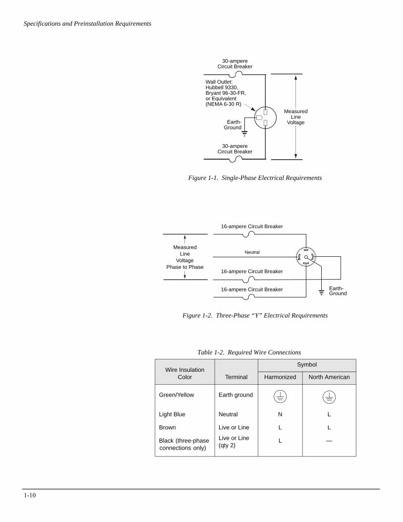
Figure 1-1 shows the power connection for single-phase centrifuges, including earth-ground and two power leads with 30-ampere circuit breakers. Figure 1-2 shows the power connection for three-phase centrifuges, including earth-ground and three power leads with minimum 16-ampere circuit breakers and common neutral connection. Table 1-2 contains wiring information.
Nominal Instrument Voltage Rating
InstrumentPart
Number
InstrumentPart Number(Elutriation System)
Nominal Supply Frequency
Power Cord and PlugDescription
Single-phase,200/208/240 V
393127 393133 180–264 VAC, 50/60 Hz, 30 A
permanently attached three-wire UL/CSA-approved cord with NEMA type 6-30P plug
Single-phase, 230 V 393128 393134 180–264 VAC,50 Hz, 30 A
permanently attached three-wire CENELEC harmonized cord without plug
Three-phase,220/380 V + Neutral*
393129 393135 313–457 VAC,plus neutral,50 Hz, 16 A
permanently attached five-wire CENELEC harmonized cord without plug
1-9
1-10
Specifications and Preinstallation Requirements
Figure 1-1. Single-Phase Electrical Requirements
Figure 1-2. Three-Phase “Y” Electrical Requirements
Table 1-2. Required Wire Connections
MeasuredLine
Voltage
Wall Outlet:Hubbell 9330,Bryant 96-30-FR,or Equivalent(NEMA 6-30 R)
Earth-Ground
30-ampereCircuit Breaker
30-ampereCircuit Breaker
MeasuredLine
VoltagePhase to Phase
Earth-Ground
16-ampere Circuit Breaker
16-ampere Circuit Breaker
16-ampere Circuit Breaker
Neutral
Wire Insulation Color Terminal
Symbol
Harmonized North American
Green/Yellow Earth ground
Light Blue Neutral N L
Brown Live or Line L L
Black (three-phase connections only)
Live or Line(qty 2)
L —
Specifications and Preinstallation Requirements
Additional Requirements for Three-phase Power Connections
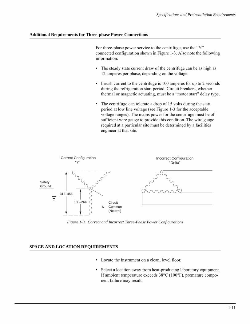
For three-phase power service to the centrifuge, use the “Y” connected configuration shown in Figure 1-3. Also note the following information:
• The steady state current draw of the centrifuge can be as high as 12 amperes per phase, depending on the voltage.
• Inrush current to the centrifuge is 100 amperes for up to 2 seconds during the refrigeration start period. Circuit breakers, whether thermal or magnetic actuating, must be a “motor start” delay type.
• The centrifuge can tolerate a drop of 15 volts during the start period at low line voltage (see Figure 1-3 for the acceptable voltage ranges). The mains power for the centrifuge must be of sufficient wire gauge to provide this condition. The wire gauge required at a particular site must be determined by a facilities engineer at that site.
Figure 1-3. Correct and Incorrect Three-Phase Power Configurations
SPACE AND LOCATION REQUIREMENTS
• Locate the instrument on a clean, level floor.
• Select a location away from heat-producing laboratory equipment. If ambient temperature exceeds 38°C (100°F), premature compo-nent failure may result.
CircuitCommon(Neutral)
SafetyGround
180–264
312–456
Incorrect Configuration“Delta”
Correct Configuration“Y”
N
1-11
1-12
Specifications and Preinstallation Requirements
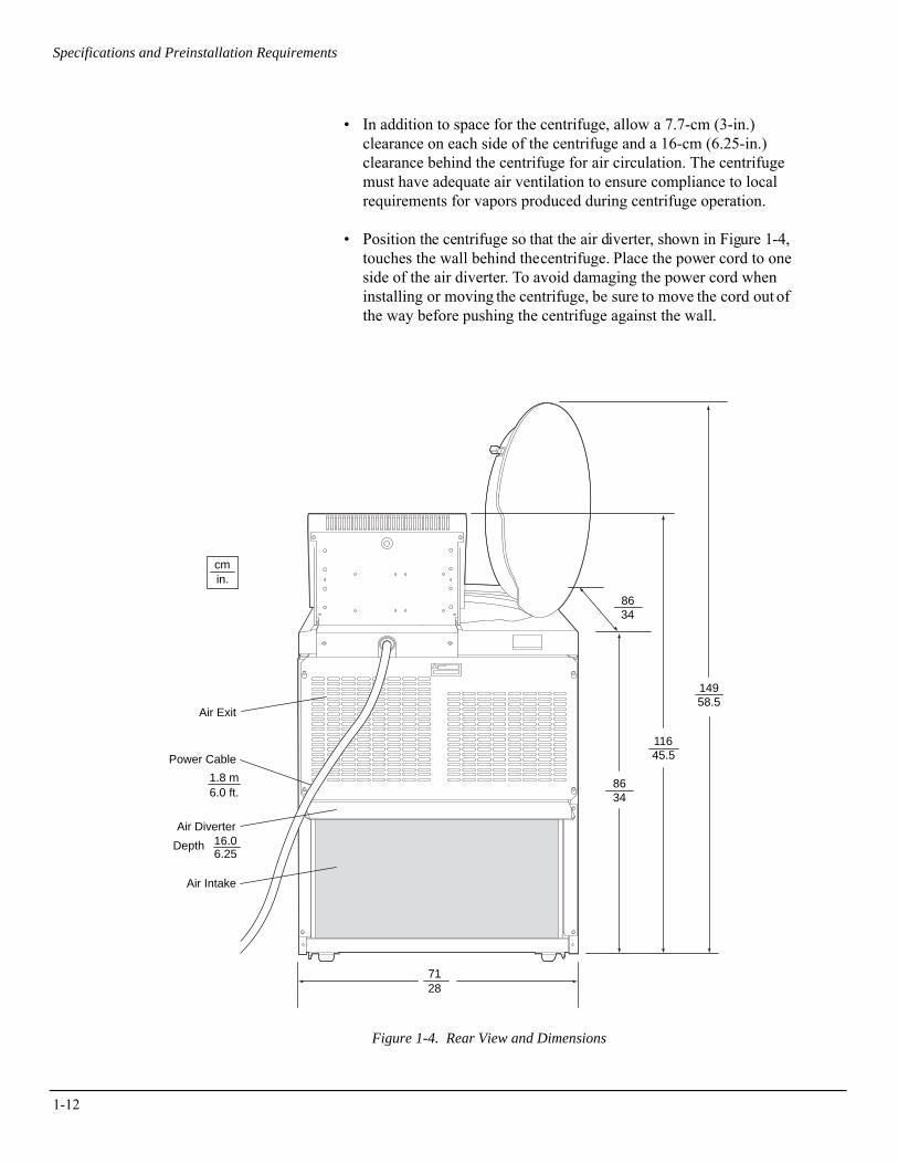
• In addition to space for the centrifuge, allow a 7.7-cm (3-in.) clearance on each side of the centrifuge and a 16-cm (6.25-in.) clearance behind the centrifuge for air circulation. The centrifuge must have adequate air ventilation to ensure compliance to local requirements for vapors produced during centrifuge operation.
• Position the centrifuge so that the air diverter, shown in Figure 1-4, touches the wall behind the centrifuge. Place the power cord to one side of the air diverter. To avoid damaging the power cord when installing or moving the centrifuge, be sure to move the cord out of the way before pushing the centrifuge against the wall.
Figure 1-4. Rear View and Dimensions
cmin.
6.0 ft.1.8 m
6.2516.0
11645.5
14958.5
8634
8634
7128
Air Exit
Depth
Air Intake
Air Diverter
Power Cable
Specifications and Preinstallation Requirements
! WARNINGDo not place the centrifuge near areas containing flammable reagents or combustible fluids. Vapors from these materials could enter the instrument’s air system and be ignited.
SECURING THE CENTRIFUGE TO THE FLOOR
Avanti J series centrifuges are certified to meet the requirements of the European CE mark. To meet these requirements, the centrifuge must be secured to the floor using the anchoring hardware shipped with the instrument. This will prevent the centrifuge from moving in the unlikely event of a rotor mishap.
Complete instructions for installing the anchoring kit are packaged with the hardware, which is shipped with the centrifuge. The instruc-tions (publication J325-TB-003) include a full-size template to be used as a guide for drilling holes in the floor. Refer to this document for additional installation instructions.
➠ NOTEBeckman Coulter representatives are not equipped to drill holes in your floor. The holes must be drilled before your scheduled installation.
BIO-SAFETY LEVEL 3 INSTALLATION
For laboratories with epoxy aggregate floors, such as BSL-3 labs, a non-invasive installation kit (PN 393316) is available. The kit which consists of an adhesive-backed mounting plate, is CSA certified for use on epoxy aggregate floors only.
1-13
1-14
Specifications and Preinstallation Requirements
USING J2 SERIES ROTORS IN THE AVANTI J
! CAUTIONDo not use the Beckman Coulter JA-10, JS-7.5, JA-14, or JS-13 rotors in the Avanti J-26XPI centrifuge before reading this information.
CHECKING FOR ROTOR DRIVE PINS
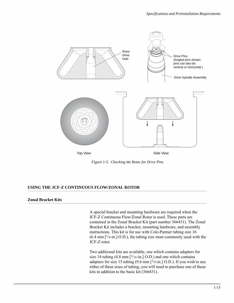
Rotors used in Avanti J series centrifuges must have drive pins in the rotor drive hole (see Figure 1-5). These drive pins engage with the centrifuge drive spindle hub to ensure that the rotor does not slip during acceleration. Some Beckman Coulter rotors, including the JA-10, the JS-7.5, the JA-14, and the JS-13, were originally manufac-tured without drive pins because these rotors did not need pins to run in older model centrifuges.
The rotor pins are positioned parallel to the BECKMAN name engraved at the center of the rotor body (see Figure 1-5). Knowing the pin orientation before you install the rotor will help to ensure that you position the rotor properly on the hub, minimizing the chance of hub damage.
Check all J2 series rotors for drive pins, and do not use rotors without drive pins in the Avanti J. To check for drive pins, hold the rotor up or turn it on its side and look into the drive hole. If you do not see two metal pins in the hole, call your local Beckman Coulter office for information on returning the rotor to the factory for upgrading.
USING THE JA-18 ROTOR
In Avanti J series centrifuges, the JA-18 rotor must be run with the lid in place. See the JA-18 rotor manual (publication J-TB-035) for complete rotor usage instructions.
Specifications and Preinstallation Requirements
Figure 1-5. Checking the Rotor for Drive Pins
USING THE JCF-Z CONTINUOUS FLOW/ZONAL ROTOR
Zonal Bracket Kits
A special bracket and mounting hardware are required when the JCF-Z Continuous Flow/Zonal Rotor is used. These parts are contained in the Zonal Bracket Kit (part number 366431). The Zonal Bracket Kit includes a bracket, mounting hardware, and assembly instructions. This kit is for use with Cole-Parmer tubing size 16 (6.4 mm [1/4-in.] O.D.), the tubing size most commonly used with the JCF-Z rotor.
Two additional kits are available, one which contains adapters for size 14 tubing (4.8 mm [3/16-in.] O.D.) and one which contains adapters for size 15 tubing (9.6 mm [3/8-in.] O.D.). If you wish to use either of these sizes of tubing, you will need to purchase one of these kits in addition to the basic kit (366431).
RotorDriveHole
Drive Pins(Angled pins shown;pins can also bevertical or horizontal.)
Drive Spindle Assembly
Top View Side View
BECKMAN
BECKMAN
1-15
1-16
Specifications and Preinstallation Requirements
See REPLACEMENT PARTS AND SUPPLIES in Section 5 for a complete list of Zonal Bracket Kit part numbers and kit contents.
Ensuring Correct JCF-Z Rotor Identification
The centrifuge’s rotor identification system can, under two specific conditions, misidentify the JCF-Z continuous flow/zonal rotor. These conditions and corrective actions are listed below.
➠ NOTEJCF-Z rotors manufactured after March, 1997, contain magnets that ensure correct rotor identification in Avanti J series centrifuges. We recommend that older JCF-Z rotors be returned to the Beckman Coulter factory for addition of the magnets before use in the Avanti J-26XPI. Call Beckman Coulter Field Service1 for more information.
The following information pertains to JCF-Z rotors manufactured before March, 1997, and to JCF-Z rotors that have not been modified at the factory.
• When the bearings in the JCF-Z rotating seal assembly get old or worn, the resulting drag on the bearings changes the rotor’s dynamic properties, making them similar to those of several Beckman Coulter fixed angle rotors. If rotor misidentification occurs when your JCF-Z rotor is used, first perform three runs from 0 to 5000 rpm and back to 0 rpm. If rotor misidentification recurs, replace the bearings. See the JCF-Z rotor instruction manual (publication JCFZ-IM) for bearing replacement instruc-tions. Be sure to follow instructions in the next paragraph for wearing in the bearings.
• On the first few uses of a new JCF-Z rotor, or when the bearings have been replaced in an older JCF-Z rotor, lubrication has not yet been thoroughly distributed around the bearings in the bearing housing. The excess lubrication produces drag on the bearings, which can change the rotor’s dynamic properties enough to cause rotor misidentification. To wear in the bearings and distribute
1 In the United States, call 1-800-742-2345. Outside the U.S., contact your local Beckman Coulter office.

Specifications and Preinstallation Requirements
the lubrication, perform three runs from 0 to 5000 rpm and back to 0 rpm.
➠ NOTEIf the JCF-Z rotor is misidentified, the run speed will be limited to the maximum speed for the identified rotor. (The maximum speed for the JCF-Z rotor is 20 000 rpm.)
1-17

2Description
This section describes the Avanti J-26 XPI centrifuge components and their functions. It also describes system safety features and centrifuge controls and displays. Refer to the applicable rotor manual for rotor descriptions.
CENTRIFUGE FUNCTION AND SAFETY FEATURES
CENTRIFUGE FUNCTION
The Avanti J-26XPI is a refrigerated centrifuge that generates centrif-ugal forces required for a wide variety of applications. Together with the Beckman Coulter rotors designed for use in this centrifuge, appli-cations include:
• Routine processing such as sample preparations, pelleting, extractions, purifications, concentrations, phase separations, and spin column and spin filter centrifugations.
• Rapid sedimentation of protein precipitates, large particles, and cell debris.
• Preparation of subcellular organelles such as mitochondria, nuclei, chloroplasts, and crude microsomes.
• Separation of blood cells and cellular components.
• Gradient separation, for example, Ficoll-Hypaque1 and Percoll.1
1 Registered trademarks of Pharmacia AB.
2-1

2-2
Description
The Avanti J-26XPI centrifuge is microprocessor-controlled, providing interactive operation.2 The instrument design features a brushless switched-reluctance drive motor,3 automatic rotor identifi-cation system, FRS (friction reduction system) vacuum control circuitry, temperature control system, and programmable acceleration and deceleration times.
The user interface consists of a separate Actual Value Display and Setup Screen, a numerical keypad, and other system control and parameter entry touch keys. User messages on the Setup Screen alert the operator to conditions that may need attention.
Manual and programmed operation are available.
• In manual operation, you enter the individual run parameters before beginning each run.
• In programmed operation, you enter and save sets of run parameters. To perform a run, you recall and start a previously saved program, enabling quick and accurate run duplication. Up to thirty programs can be saved, each containing one or two steps.
User messages and/or audible signals are provided to alert you to conditions that may need attention.
The centrifuge can also be operated by the SpinTrace™ II system for centrifuge control and data collection. SpinTrace II software runs on a personal computer connected to up to thirty-two centrifuges. Contact your Beckman Coulter representative for more information.
SAFETY FEATURES
Avanti J-26 XPI centrifuges have been designed and tested to operate safely indoors at altitudes up to 2 000 m (6 562 ft).
Safety features include the following.
• An electromechanical door lock system prevents operator contact with spinning rotors and prevents run initiation unless the door is closed and locked. The door locks when [ENTER] and [START] are pressed, or when the POWER switch is turned off. The exception to this is ZONAL mode, in which open-door operation up to 3000 rpm is allowed.
• A steel casing surrounds the rotor chamber to provide operator protection in the unlikely event of a rotor mishap.
2 Avanti® J-26XPI software and firmware copyright ©2005 by Beckman Coulter, Inc., Palo Alto, CA, U.S.A.3 Manufactured under license from Switched Reluctance Drives Limited, Harrogate, U.K.
Description
• Dynamic Rotor Inertia Check (DRIC): As the rotor accelerates, rotor inertia is measured and the rotor energy is calculated for the speed set by the user. If the calculated rotor energy is determined to be excessive, the centrifuge recalculates a permitted set speed and uses this value to avoid possible rotor damage. A diagnostic message is displayed to indicate the change.
• An imbalance detector monitors the system during operation, causing automatic shutdown if rotor loads are severely out of balance.
HOUSING AND DOOR
The instrument control housing is made of aluminum and molded structural foam. The door and structural-foam cover panels are finished with polyurethane enamel. The control panel is covered by a protective overlay made of coated polycarbonate.
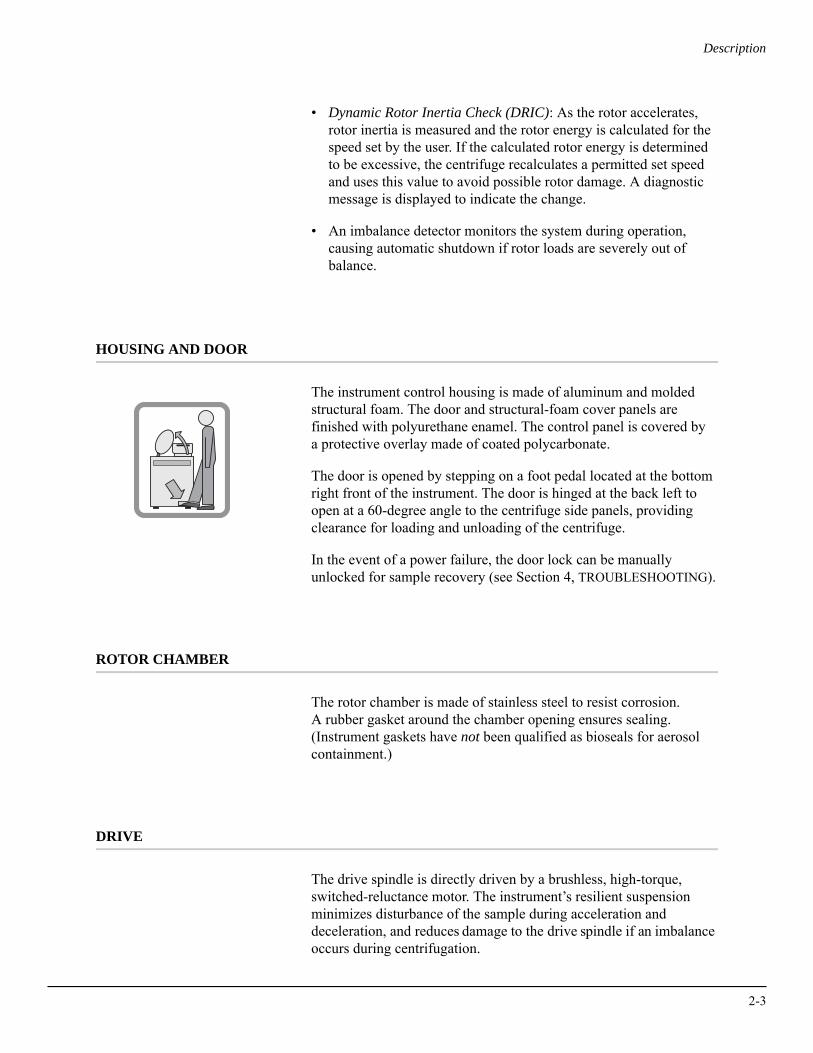
The door is opened by stepping on a foot pedal located at the bottom right front of the instrument. The door is hinged at the back left to open at a 60-degree angle to the centrifuge side panels, providing clearance for loading and unloading of the centrifuge.
In the event of a power failure, the door lock can be manually unlocked for sample recovery (see Section 4, TROUBLESHOOTING).
ROTOR CHAMBER
The rotor chamber is made of stainless steel to resist corrosion. A rubber gasket around the chamber opening ensures sealing. (Instrument gaskets have not been qualified as bioseals for aerosol containment.)
DRIVE
The drive spindle is directly driven by a brushless, high-torque, switched-reluctance motor. The instrument’s resilient suspension minimizes disturbance of the sample during acceleration and deceleration, and reduces damage to the drive spindle if an imbalance occurs during centrifugation.
2-3
2-4
Description
FRICTION REDUCTION SYSTEM (FRS)
The friction reduction system (FRS) uses a mechanical rotary vane vacuum pump to reduce chamber pressure to approximately one-quarter atmosphere (190 mm Hg). The pump turns on after the run is started, before rotor friction reaches a high level. When the required vacuum level is reached, the pump turns off. Vacuum in the chamber is vented during rotor deceleration.
TEMPERATURE SENSING AND CONTROL
The temperature control system is cooled by circulation of a non-CFC-based refrigerant. The temperature control system is acti-vated when the centrifuge power is on and when the door is closed.
A thermistor in the rotor chamber continuously monitors the chamber temperature. The system calculates the chamber temperature required to maintain the set rotor temperature, ±2°C.4 Although the chamber temperature fluctuates during operation, the rotor’s large mass keeps the sample temperature substantially constant. At the end of a run, the system continues controlling the temperature to prevent freezing or overheating of the sample.
OVERTEMP SYSTEM
An overtemp (over temperature) system provides flexibility, sample protection, and safety for the user.
• The user sets the run temperature, then sets a maximum tempera-ture or accepts the default maximum temperature which is 4°C over the set temperature.
• The user specifies whether the run should shut down or continue if the overtemp setting is reached.
• The system will always shut down using maximum brake if the temperature goes above 50°C.
4 Refer to the applicable rotor manual for specific temperature information.
Description
NAME RATING PLATE
The name rating plate is affixed to the rear of the centrifuge. Always mention the model number and serial number when corresponding with Beckman Coulter regarding your centrifuge.
CONTROLS AND INDICATORS
KEY AND POWER SWITCHES
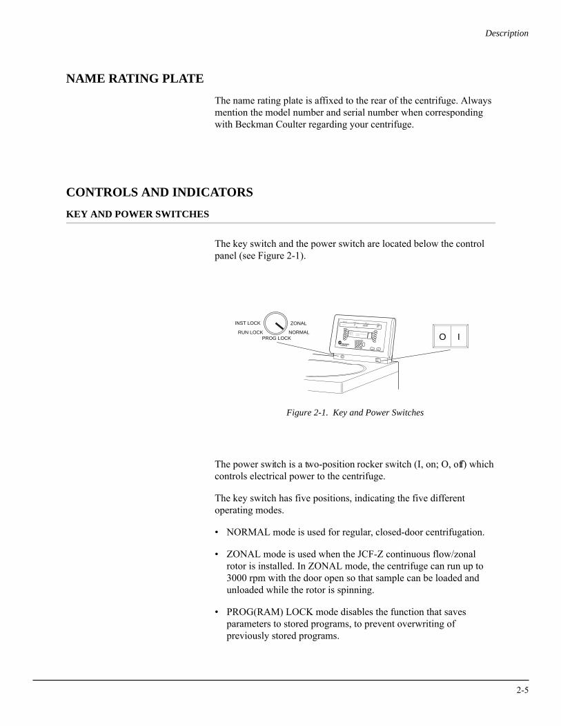
The key switch and the power switch are located below the control panel (see Figure 2-1).
Figure 2-1. Key and Power Switches
The power switch is a two-position rocker switch (I, on; O, off) which controls electrical power to the centrifuge.
The key switch has five positions, indicating the five different operating modes.
• NORMAL mode is used for regular, closed-door centrifugation.
• ZONAL mode is used when the JCF-Z continuous flow/zonal rotor is installed. In ZONAL mode, the centrifuge can run up to 3000 rpm with the door open so that sample can be loaded and unloaded while the rotor is spinning.
• PROG(RAM) LOCK mode disables the function that saves parameters to stored programs, to prevent overwriting of previously stored programs.
O IZONAL
NORMAL
INST LOCK
RUN LOCKPROG LOCK
START
ROTOR
SPEED
TIME
TEMP
A/D
OPT
ROTOR: JA-20
RPMRCF
TIME: 00:00TEMP: 25°C MAX TEMP : 29°C SHUTDOWN? YESACCEL: MAX DECEL: MAX
CE
3
6
9
2
+
5
8
1
0
4
7
ENTER
STOP
.
TM
2-5
2-6
Description
• RUN LOCK mode disables all user inputs except [START] and [STOP] to ensure that current settings do not get changed.
• INST(RUMENT) LOCK mode disables all user inputs except [STOP], to prevent use of the instrument after the current run is complete.
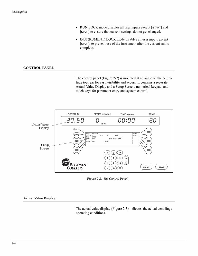
CONTROL PANEL
The control panel (Figure 2-2) is mounted at an angle on the centri-fuge top rear for easy visibility and access. It contains a separate Actual Value Display and a Setup Screen, numerical keypad, and touch keys for parameter entry and system control.
Figure 2-2. The Control Panel
Actual Value Display
The actual value display (Figure 2-3) indicates the actual centrifuge operating conditions.
ROTOR ID SPEED RPM/RCF TIME HR:MIN °CTEMP
START STOP
ENTER
7 8 9
4 5 6
1 2 3
0 ±. CE
Actual ValueDisplay
SetupScreen
Rotor : JA-30.50 Speed : 0 RPM = x GTime : 00:00Temp : 25°C Max Temp : 29°C
RPMRCF
Accel : MAX Decel :
SPEED
TIME
TEMP
A/D
OPT
ROTOR
RPM
®
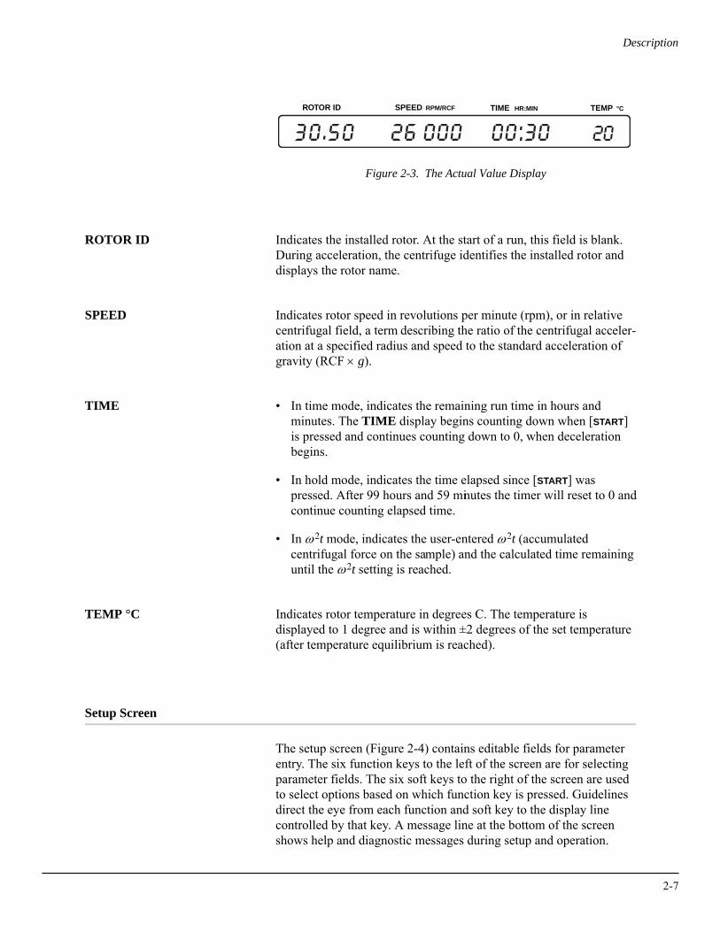
Description
Figure 2-3. The Actual Value Display
ROTOR ID Indicates the installed rotor. At the start of a run, this field is blank. During acceleration, the centrifuge identifies the installed rotor and displays the rotor name.
SPEED Indicates rotor speed in revolutions per minute (rpm), or in relative centrifugal field, a term describing the ratio of the centrifugal acceler-ation at a specified radius and speed to the standard acceleration of gravity (RCF × g).
TIME • In time mode, indicates the remaining run time in hours and minutes. The TIME display begins counting down when [START] is pressed and continues counting down to 0, when deceleration begins.
• In hold mode, indicates the time elapsed since [START] was pressed. After 99 hours and 59 minutes the timer will reset to 0 and continue counting elapsed time.
• In ω2t mode, indicates the user-entered ω2t (accumulated centrifugal force on the sample) and the calculated time remaining until the ω2t setting is reached.
TEMP °C Indicates rotor temperature in degrees C. The temperature is displayed to 1 degree and is within ±2 degrees of the set temperature (after temperature equilibrium is reached).
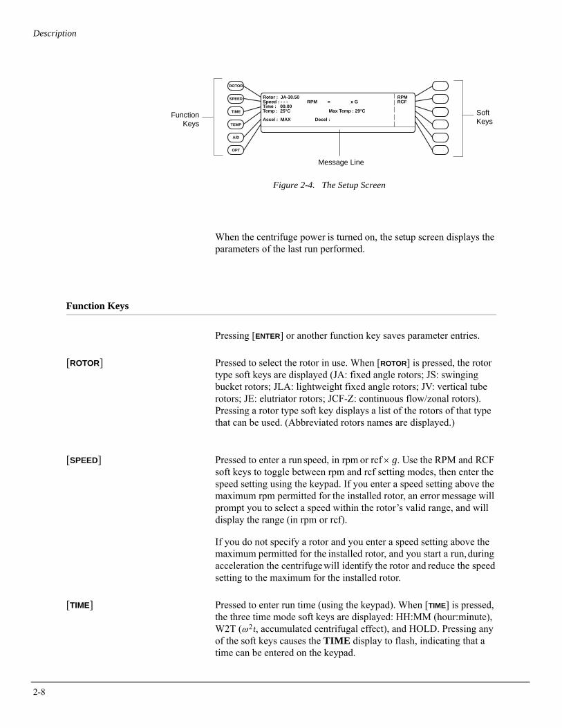
Setup Screen
The setup screen (Figure 2-4) contains editable fields for parameter entry. The six function keys to the left of the screen are for selecting parameter fields. The six soft keys to the right of the screen are used to select options based on which function key is pressed. Guidelines direct the eye from each function and soft key to the display line controlled by that key. A message line at the bottom of the screen shows help and diagnostic messages during setup and operation.
ROTOR ID SPEED RPM/RCF TIME HR:MIN °CTEMP
2-7
2-8
Description
Figure 2-4. The Setup Screen
When the centrifuge power is turned on, the setup screen displays the parameters of the last run performed.
Function Keys
Pressing [ENTER] or another function key saves parameter entries.
[ROTOR] Pressed to select the rotor in use. When [ROTOR] is pressed, the rotor type soft keys are displayed (JA: fixed angle rotors; JS: swinging bucket rotors; JLA: lightweight fixed angle rotors; JV: vertical tube rotors; JE: elutriator rotors; JCF-Z: continuous flow/zonal rotors). Pressing a rotor type soft key displays a list of the rotors of that type that can be used. (Abbreviated rotors names are displayed.)
[SPEED] Pressed to enter a run speed, in rpm or rcf × g. Use the RPM and RCF soft keys to toggle between rpm and rcf setting modes, then enter the speed setting using the keypad. If you enter a speed setting above the maximum rpm permitted for the installed rotor, an error message will prompt you to select a speed within the rotor’s valid range, and will display the range (in rpm or rcf).
If you do not specify a rotor and you enter a speed setting above the maximum permitted for the installed rotor, and you start a run, during acceleration the centrifuge will identify the rotor and reduce the speed setting to the maximum for the installed rotor.
[TIME] Pressed to enter run time (using the keypad). When [TIME] is pressed, the three time mode soft keys are displayed: HH:MM (hour:minute), W2T (ω2t, accumulated centrifugal effect), and HOLD. Pressing any of the soft keys causes the TIME display to flash, indicating that a time can be entered on the keypad.
FunctionKeys
Soft Keys
Message Line
Rotor : JA-30.50 Speed : - - - RPM = x GTime : 00:00Temp : 25°C Max Temp : 29°C
RPMRCF
Accel : MAX Decel :
SPEED
TIME
TEMP
A/D
OPT
ROTOR
Description
• Timed run (HH:MM) — Run time up to 99 hours and 59 minutes can be set. If more than 59 minutes are entered in the minutes field, the system automatically converts the entry to hours and minutes. Decelerating begins when the set time counts down to zero. The corresponding ω2t value can be displayed by pressing the W2T soft key.
• ω2t run — An ω2t value can be entered and the system will calcu-late the run time required to reach that value. Valid ω2t settings are different for each rotor; a user message will appear if an invalid entry is made. Deceleration begins when the calculated run time counts down to zero, but ω2t continues accumulating until the rotor stops spinning.
• Continuous run (hold) — For runs of unspecified lengths, hold mode is used. The display will show the accumulated run time. When 99 hours, 59 minutes is reached, the system resets to 0 and continues counting. The run will continue until the [STOP] key is pressed.
[TEMP] Pressed to enter run temperature (using the keypad), from –10°C to +40°C.
• The minimum allowable set temperature depends on the set speed and the rotor in use. If a temperature is entered that cannot be achieved by the rotor at the set speed, the TEMP°C field will flash.
• The maximum achievable rotor temperature depends on the fric-tional heat generated inside the chamber during operation. At low run speeds or low ambient temperature, the centrifuge may not be able to achieve some higher temperatures.
[A/D] If, during acceleration, the system identifies a rotor different from the rotor entered by the user, or if the set speed is changed during opera-tion, the set temperature may no longer be achievable. If this happens, the TEMP°C field will flash indicating that a different temperature must be entered.
Pressed to enter acceleration and deceleration rates that will maintain optimum separation while protecting samples. When [A/D] is pressed, the Accel: field flashes, prompting you to enter an acceleration setting. Pressing [A/D] once more moves the cursor to the Decel: field.
Available acceleration rates are maximum, slow, and timed (1 to 10 minutes from 0 to 500 rpm). Available deceleration rates are maximum, slow, timed (1 to 10 minutes from 500 to 0 rpm), and no brake (off).
2-9
2-10
Description
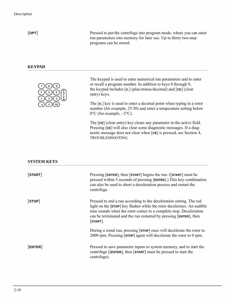
[OPT] Pressed to put the centrifuge into program mode, where you can enter run parameters into memory for later use. Up to thirty two-step programs can be stored.
KEYPAD
The keypad is used to enter numerical run parameters and to enter or recall a program number. In addition to keys 0 through 9, the keypad includes [±.] (plus/minus/decimal) and [CE] (clear entry) keys.
The [±.] key is used to enter a decimal point when typing in a rotor number (for example, 25.50) and enter a temperature setting below 0°C (for example, –2°C).
The [CE] (clear entry) key clears any parameter in the active field. Pressing [CE] will also clear some diagnostic messages. If a diag-nostic message does not clear when [CE] is pressed, see Section 4, TROUBLESHOOTING.
SYSTEM KEYS
[START] Pressing [ENTER], then [START] begins the run. ([START] must be pressed within 5 seconds of pressing [ENTER].) This key combination can also be used to abort a deceleration process and restart the centrifuge.
[STOP] Pressed to end a run according to the deceleration setting. The red light on the [STOP] key flashes while the rotor decelerates. An audible tone sounds when the rotor comes to a complete stop. Deceleration can be terminated and the run restarted by pressing [ENTER], then [START].
During a zonal run, pressing [STOP] once will decelerate the rotor to 2000 rpm. Pressing [STOP] again will decelerate the rotor to 0 rpm.
[ENTER] Pressed to save parameter inputs to system memory, and to start the centrifuge ([ENTER], then [START] must be pressed to start the centrifuge).
ENTER
7 8 9
4 5 6
1 2 3
0 ±. CE
3Operation
This section contains detailed centrifuge operating procedures. A summary is provided at the start of this section. If you are an experi-enced user of this centrifuge, you can turn to the summary for a quick review of operating steps.
! WARNINGNormal operation may involve the use of solutions and test samples that are patho-genic, toxic, or radioactive. Handle body fluids with care because they can transmit disease. No known test offers complete assur-ance that they are free of micro-organisms. Some of the most virulent—Hepatitis (B and C) and HIV (I–V) viruses, atypical mycobac-teria, and certain systemic fungi—further emphasize the need for aerosol protection. Handle other infectious samples according to good laboratory procedures and methods to prevent spread of disease. Because spills may generate aerosols, observe proper precautions for aerosol containment. Do not run toxic, pathogenic, or radioactive materials in this centrifuge without taking appropriate safety precautions. Biosafe containment should be used when Risk Group II materials (as identified in the World Health Organization Laboratory Biosafety Manual) are handled; materials of a higher group require more than one level of protection.
Do not use the centrifuge in the vicinity of flammable liquids or vapors, and do not run such materials in the centrifuge. Do not lean on the centrifuge or place items on it while it is operating.
3-1
3-2
Operation
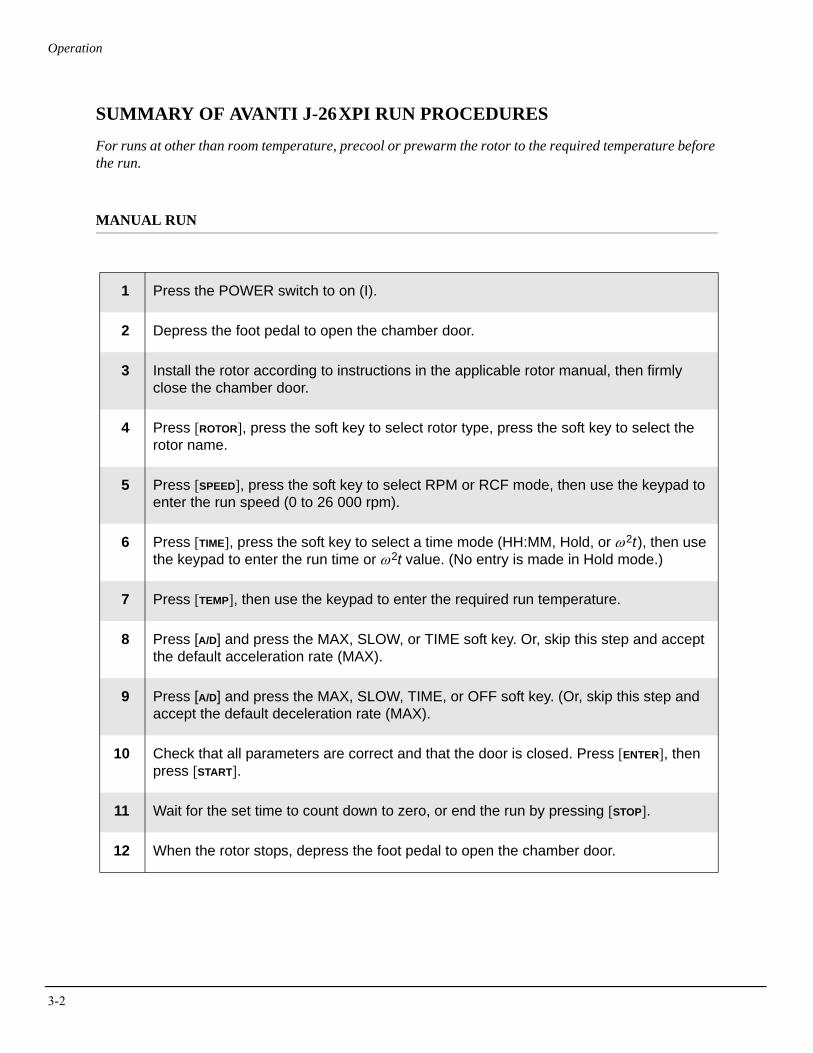
SUMMARY OF AVANTI J-26XPI RUN PROCEDURES
For runs at other than room temperature, precool or prewarm the rotor to the required temperature before the run.
MANUAL RUN
1 Press the POWER switch to on (I).
2 Depress the foot pedal to open the chamber door.
3 Install the rotor according to instructions in the applicable rotor manual, then firmly close the chamber door.
4 Press [ROTOR], press the soft key to select rotor type, press the soft key to select the rotor name.
5 Press [SPEED], press the soft key to select RPM or RCF mode, then use the keypad to enter the run speed (0 to 26 000 rpm).
6 Press [TIME], press the soft key to select a time mode (HH:MM, Hold, or ω2t), then use the keypad to enter the run time or ω2t value. (No entry is made in Hold mode.)
7 Press [TEMP], then use the keypad to enter the required run temperature.
8 Press [A/D] and press the MAX, SLOW, or TIME soft key. Or, skip this step and accept the default acceleration rate (MAX).
9 Press [A/D] and press the MAX, SLOW, TIME, or OFF soft key. (Or, skip this step and accept the default deceleration rate (MAX).
10 Check that all parameters are correct and that the door is closed. Press [ENTER], then press [START].
11 Wait for the set time to count down to zero, or end the run by pressing [STOP].
12 When the rotor stops, depress the foot pedal to open the chamber door.
Operation
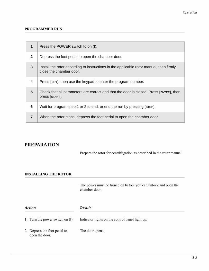
PROGRAMMED RUN
PREPARATION
Prepare the rotor for centrifugation as described in the rotor manual.
INSTALLING THE ROTOR
The power must be turned on before you can unlock and open the chamber door.
Action Result
1. Turn the power switch on (I). Indicator lights on the control panel light up.
2. Depress the foot pedal to open the door.
The door opens.
1 Press the POWER switch to on (I).
2 Depress the foot pedal to open the chamber door.
3 Install the rotor according to instructions in the applicable rotor manual, then firmly close the chamber door.
4 Press [OPT], then use the keypad to enter the program number.
5 Check that all parameters are correct and that the door is closed. Press [ENTER], then press [START].
6 Wait for program step 1 or 2 to end, or end the run by pressing [STOP].
7 When the rotor stops, depress the foot pedal to open the chamber door.
3-3
3-4
Operation
Action Result
3. Install the rotor according to the instructions in therotor manual. Make surethat the rotor is seated onthe drive hub.
! CAUTIONDo not drop the rotor onto the drive hub. The drive spindle can be bent if the rotor is forced sideways or dropped onto the spindle hub. Install the rotor by centering it over the hub and carefully lowering it straight down.
4. Securely attach the rotor lid knob, or tie-down knob in rotors without lids, to the drive shaft by turning it to the right (clockwise).
➠ NOTEIf the knob turns loosely and you do not feel threads engaging, the rotor drive hole pins may not be properly seated on the centrifuge hub. Lift the rotor up, rotate it slightly, and lower it onto the hub again. Tighten the knob.
5. Close the chamber door.
! CAUTIONIf you leave the rotor in the centrifuge between runs, make sure the rotor is seated on the drive hub and the tie-down knob is tight before each run.
MANUAL OPERATION
• When a function key ([ROTOR], [SPEED], [TIME], [TEMP], [A/D], or [OPT]) is pressed, the corresponding setup screen field blinks to indicate that a parameter can be entered or changed. The field continues to blink until [ENTER] or another function key is pressed.
• To change an entry before you’ve pressed [ENTER], press [CE] and enter a different value. To change an entry after you’ve pressed [ENTER], press the function key again.
• If an invalid setting is entered, the display blinks and the valid range for that parameter is displayed in the message line. A valid parameter must be entered and [ENTER] must be pressed before you can enter another parameter.
Operation
SELECTING A ROTOR
Action Result
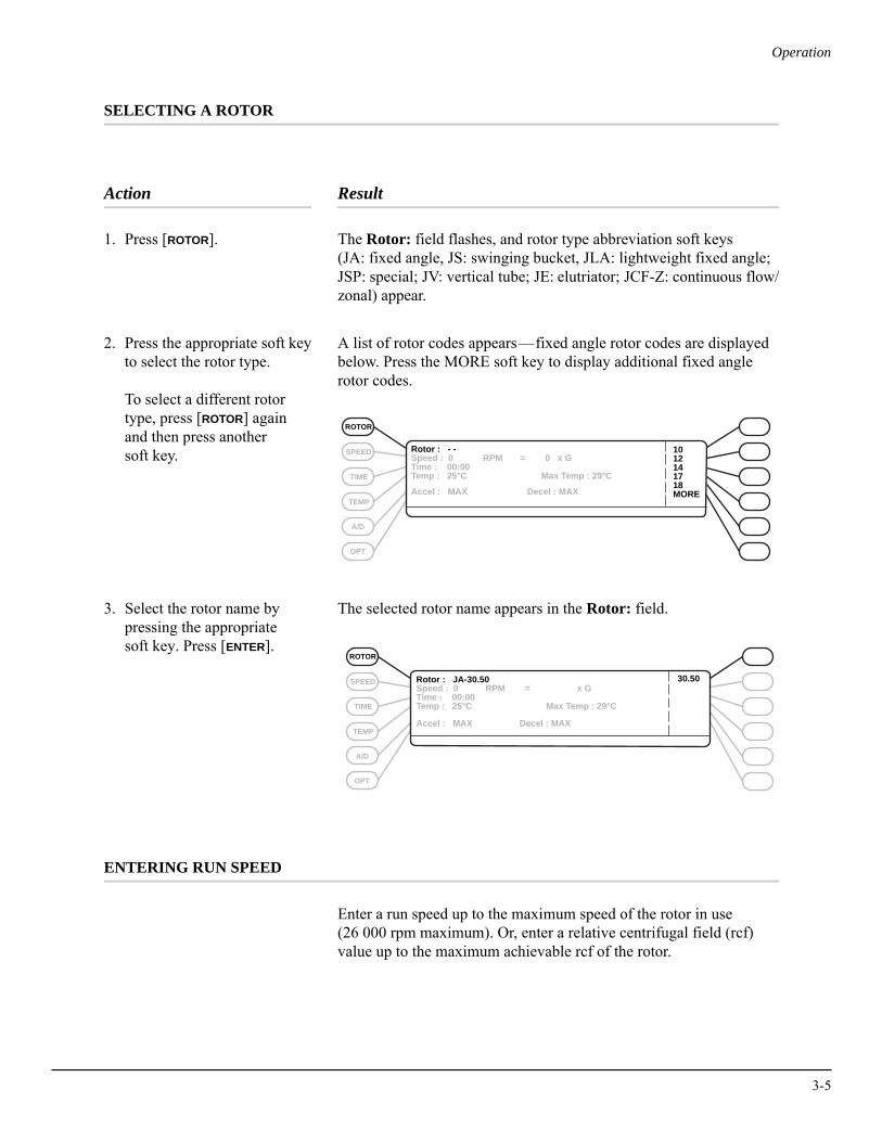
1. Press [ROTOR]. The Rotor: field flashes, and rotor type abbreviation soft keys (JA: fixed angle, JS: swinging bucket, JLA: lightweight fixed angle; JSP: special; JV: vertical tube; JE: elutriator; JCF-Z: continuous flow/zonal) appear.
2. Press the appropriate soft keyto select the rotor type.
To select a different rotortype, press [ROTOR] againand then press another soft key.
A list of rotor codes appears—fixed angle rotor codes are displayed below. Press the MORE soft key to display additional fixed angle rotor codes.
3. Select the rotor name by pressing the appropriate soft key. Press [ENTER].
The selected rotor name appears in the Rotor: field.
ENTERING RUN SPEED
Enter a run speed up to the maximum speed of the rotor in use (26 000 rpm maximum). Or, enter a relative centrifugal field (rcf) value up to the maximum achievable rcf of the rotor.
Rotor : - -Speed : 0 RPM = 0 x GTime : 00:00Temp : 25°C Max Temp : 29°C
Accel : MAX Decel : MAX
1012141718MORE
SPEED
TIME
TEMP
A/D
OPT
ROTOR
Rotor : JA-30.50 Speed : 0 RPM = x GTime : 00:00Temp : 25°C Max Temp : 29°C
Accel : MAX Decel : MAX
30.50SPEED
TIME
TEMP
A/D
OPT
ROTOR
3-5
3-6
Operation
Entering RPM
Action Result
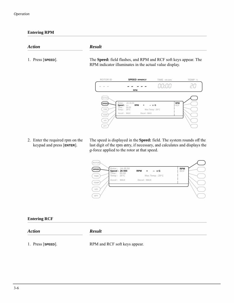
1. Press [SPEED]. The Speed: field flashes, and RPM and RCF soft keys appear. The RPM indicator illuminates in the actual value display.
2. Enter the required rpm on the keypad and press [ENTER].
The speed is displayed in the Speed: field. The system rounds off the last digit of the rpm entry, if necessary, and calculates and displays the g-force applied to the rotor at that speed.
Entering RCF
Action Result
1. Press [SPEED]. RPM and RCF soft keys appear.
ROTOR
TIME
TEMP
A/D
OPT
ROTOR ID SPEED RPM/RCF TIME HR:MIN °CTEMP
Rotor : JA-30.50 Speed : - - RPM = -- x GTime : 00:00Temp : 25°C Max Temp : 29°CAccel : MAX Decel : MAX
RPMRCF
RPM
SPEED
SPEED
TIME
TEMP
A/D
OPT
ROTOR
Rotor : JA-30.50 Speed : 26 000 RPM = -- x GTime : 00:00Temp : 25°C Max Temp : 29°C
Accel : MAX Decel : MAX
RPMRCF
Operation
Action Result
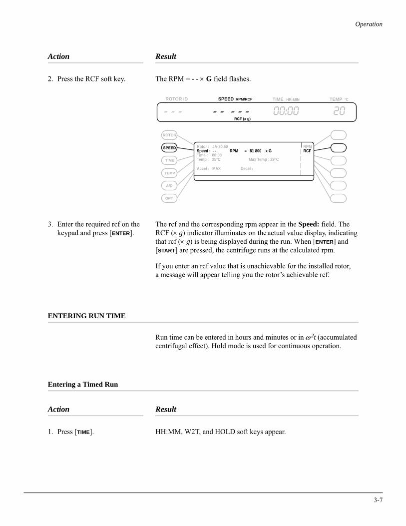
2. Press the RCF soft key. The RPM = - - × G field flashes.
3. Enter the required rcf on the keypad and press [ENTER].
The rcf and the corresponding rpm appear in the Speed: field. The RCF (× g) indicator illuminates on the actual value display, indicating that rcf (× g) is being displayed during the run. When [ENTER] and [START] are pressed, the centrifuge runs at the calculated rpm.
If you enter an rcf value that is unachievable for the installed rotor, a message will appear telling you the rotor’s achievable rcf.
ENTERING RUN TIME
Run time can be entered in hours and minutes or in ω2t (accumulated centrifugal effect). Hold mode is used for continuous operation.
Entering a Timed Run
Action Result
1. Press [TIME]. HH:MM, W2T, and HOLD soft keys appear.
SPEED
TIME
TEMP
A/D
OPT
ROTOR
ROTOR ID SPEED RPM/RCF TIME HR:MIN °CTEMP
Rotor : JA-30.50 Speed : - - RPM = 81 800 x GTime : 00:00Temp : 25°C Max Temp : 29°C
Accel : MAX Decel :
RPMRCF
RCF (x g)
3-7
3-8
Operation
Action Result
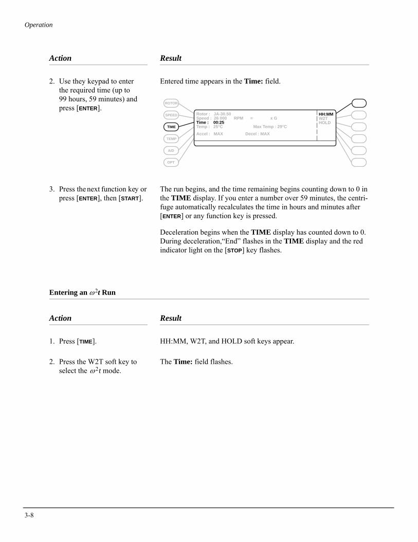
2. Use they keypad to enter the required time (up to 99 hours, 59 minutes) and press [ENTER].
Entered time appears in the Time: field.
3. Press the next function key or press [ENTER], then [START].
The run begins, and the time remaining begins counting down to 0 in the TIME display. If you enter a number over 59 minutes, the centri-fuge automatically recalculates the time in hours and minutes after [ENTER] or any function key is pressed.
Deceleration begins when the TIME display has counted down to 0. During deceleration,“End” flashes in the TIME display and the red indicator light on the [STOP] key flashes.
Entering an ω2t Run
Action Result
1. Press [TIME]. HH:MM, W2T, and HOLD soft keys appear.
2. Press the W2T soft key to select the ω2t mode.
The Time: field flashes.
SPEED
TIME
TEMP
A/D
OPT
ROTOR
Rotor : JA-30.50 Speed : 26 000 RPM = x GTime : 00:25Temp : 25°C Max Temp : 29°CAccel : MAX Decel : MAX
HH:MMW2THOLD
Operation
Action Result
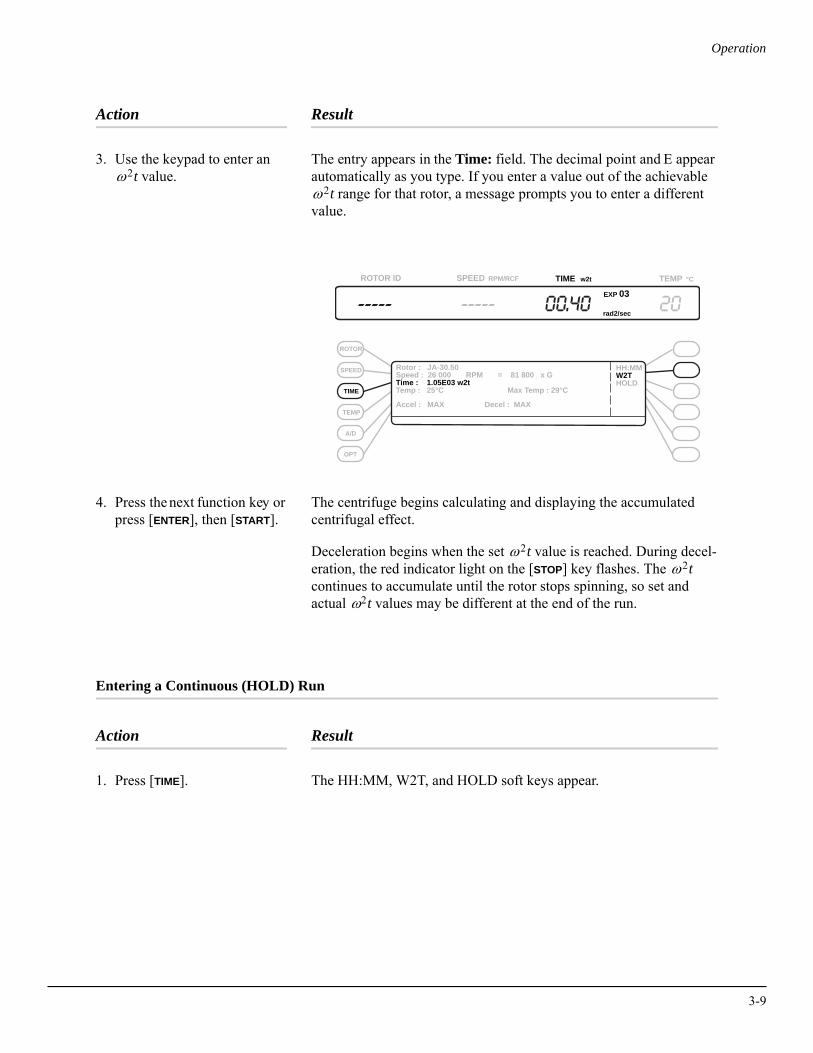
3. Use the keypad to enter an ω2t value.
The entry appears in the Time: field. The decimal point and E appear automatically as you type. If you enter a value out of the achievable ω2t range for that rotor, a message prompts you to enter a different value.
4. Press the next function key or press [ENTER], then [START].
The centrifuge begins calculating and displaying the accumulated centrifugal effect.
Deceleration begins when the set ω2t value is reached. During decel-eration, the red indicator light on the [STOP] key flashes. The ω2t continues to accumulate until the rotor stops spinning, so set and actual ω2t values may be different at the end of the run.
Entering a Continuous (HOLD) Run
Action Result
1. Press [TIME]. The HH:MM, W2T, and HOLD soft keys appear.
SPEED
TIME
TEMP
A/D
OPT
ROTOR
ROTOR ID SPEED RPM/RCF TIME w2t °CTEMP
Rotor : JA-30.50 Speed : 26 000 RPM = 81 800 x GTime : 1.05E03 w2tTemp : 25°C Max Temp : 29°C
HH:MMW2THOLD
Accel : MAX Decel : MAX
EXP 03
rad2/sec
3-9

3-10
Operation
Action Result
2. Press the HOLD soft key to select the hold mode.
HOLD appears in the Time: field.
3. Press the next function key or press [ENTER], then [START].
After you start the run, the HOLD indicator illuminates in the TIME display. The elapsed run time is displayed. The run continues until [STOP] is pressed.
ENTERING RUN TEMPERATURE
Run temperature can be set from –10 to +40°C. If no value is entered, the last-entered temperature is used.
Action Result
1. Press [TEMP]. The Temp: field flashes.
ROTOR ID SPEED RPM/RCF TIME HR:MIN °CTEMP
Rotor : JA-30.50 Speed : 26 000 RPM = 81 800 x GTime : 00:00Temp : 25°C Max Temp : 29°C
HH:MMW2THOLD
HOLD
Accel : MAX Decel : MAX
SPEED
TIME
TEMP
A/D
OPT
ROTOR
SPEED
TIME
TEMP
A/D
OPT
ROTOR
Rotor : JA-30.50 Speed : 26 000 RPM = 81 800 x GTime : 00:00Temp: - - Max Temp : - - °C
Accel : MAX Decel : MAX
Operation
Action Result
2. Use the keypad to enter the required temperature.
Entered temperature appears in the Temp: field.
3. Press the [TEMP] key again to move the cursor to the Max Temp: field.
Entered temperature plus 4°C appears in the Max Temp: field, and YES and NO soft keys appear. The default maximum temperature is the set temperature plus 4°C. You can specify a different maximum temperature, from +2°C above the set temperature to 44°C. You can also specify whether or not you want the system to shut down if the maximum temperature is reached. The centrifuge will always shut down if the system temperature reaches 50°C.
4. Use the keypad to enter a different maximum tempera-ture, or accept the default.
5. Choose YES to make the system shut down at maximum temperature, or NO to allow the system to run above maximum temperature.
Your selection (YES or NO) appears to the right of the Max Temp: field.
ENTERING ACCELERATION AND DECELERATION RATES
The centrifuge provides a choice of three acceleration rates and four deceleration rates to protect the gradient and sample-to-gradient interface. Table 3-1 describes these rates. If no rate is selected, the centrifuge accelerates and decelerates at maximum rates.
The default setting for both acceleration and deceleration is maximum (MAX) for all rotors except the JS-24.38 and the JS-24.15. Maximum acceleration and deceleration are not available for these rotors. SLOW is the default setting; TIMED settings can also be used.
3-11
3-12
Operation
Table 3-1. Acceleration and Deceleration Settings
Acceleration
Action Result
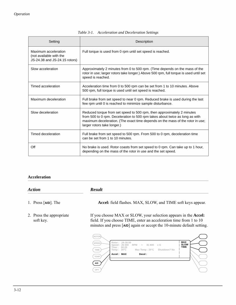
1. Press [A/D]. The Accel: field flashes. MAX, SLOW, and TIME soft keys appear.
2. Press the appropriate soft key.
If you choose MAX or SLOW, your selection appears in the Accel: field. If you choose TIME, enter an acceleration time from 1 to 10 minutes and press [A/D] again or accept the 10-minute default setting.
Setting Description
Maximum acceleration(not available with the JS-24.38 and JS-24.15 rotors)
Full torque is used from 0 rpm until set speed is reached.
Slow acceleration Approximately 2 minutes from 0 to 500 rpm. (Time depends on the mass of the rotor in use; larger rotors take longer.) Above 500 rpm, full torque is used until set speed is reached.
Timed acceleration Acceleration time from 0 to 500 rpm can be set from 1 to 10 minutes. Above 500 rpm, full torque is used until set speed is reached.
Maximum deceleration Full brake from set speed to near 0 rpm. Reduced brake is used during the last few rpm until 0 is reached to minimize sample disturbance.
Slow deceleration Reduced torque from set speed to 500 rpm, then approximately 2 minutes from 500 to 0 rpm. Deceleration to 500 rpm takes about twice as long as with maximum deceleration. (The exact time depends on the mass of the rotor in use; larger rotors take longer.)
Timed deceleration Full brake from set speed to 500 rpm. From 500 to 0 rpm, deceleration time can be set from 1 to 10 minutes.
Off No brake is used. Rotor coasts from set speed to 0 rpm. Can take up to 1 hour, depending on the mass of the rotor in use and the set speed.
SPEED
TIME
TEMP
A/D
OPT
ROTOR
Rotor : JA-30.50 Speed : 26 000 RPM = 81 800 x GTime : 00:25Temp : 20°C Max Temp : 24°C Shutdown? No
MAXSLOWTIME
Accel : MAX Decel :
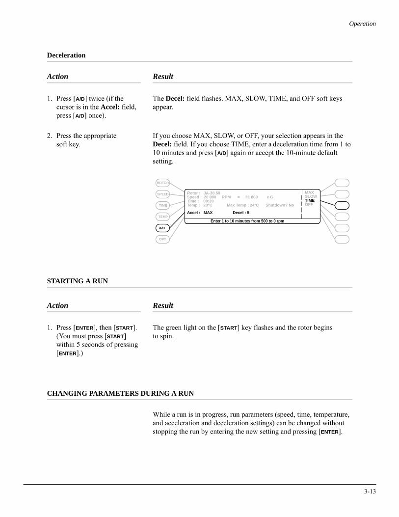
Operation
Deceleration
Action Result
1. Press [A/D] twice (if the cursor is in the Accel: field, press [A/D] once).
The Decel: field flashes. MAX, SLOW, TIME, and OFF soft keys appear.
2. Press the appropriate soft key.
If you choose MAX, SLOW, or OFF, your selection appears in the Decel: field. If you choose TIME, enter a deceleration time from 1 to 10 minutes and press [A/D] again or accept the 10-minute default setting.
STARTING A RUN
Action Result
1. Press [ENTER], then [START]. (You must press [START] within 5 seconds of pressing [ENTER].)
The green light on the [START] key flashes and the rotor begins to spin.
CHANGING PARAMETERS DURING A RUN
While a run is in progress, run parameters (speed, time, temperature, and acceleration and deceleration settings) can be changed without stopping the run by entering the new setting and pressing [ENTER].
SPEED
TIME
TEMP
A/D
OPT
ROTOR
Rotor : JA-30.50 Speed : 26 000 RPM = 81 800 x GTime : 00:20Temp : 20°C Max Temp : 24°C Shutdown? No
MAXSLOWTIMEOFF
Accel : MAX Decel : 5
Enter 1 to 10 minutes from 500 to 0 rpm
3-13
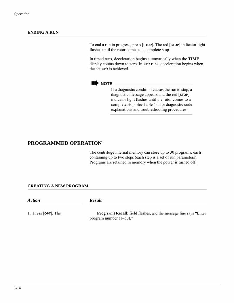
3-14
Operation
ENDING A RUN
To end a run in progress, press [STOP]. The red [STOP] indicator light flashes until the rotor comes to a complete stop.
In timed runs, deceleration begins automatically when the TIME display counts down to zero. In ω2t runs, deceleration begins when the set ω2t is achieved.
➠ NOTEIf a diagnostic condition causes the run to stop, a diagnostic message appears and the red [STOP] indicator light flashes until the rotor comes to a complete stop. See Table 4-1 for diagnostic code explanations and troubleshooting procedures.
PROGRAMMED OPERATION
The centrifuge internal memory can store up to 30 programs, each containing up to two steps (each step is a set of run parameters). Programs are retained in memory when the power is turned off.
CREATING A NEW PROGRAM
Action Result
1. Press [OPT]. The Prog(ram) Recall: field flashes, and the message line says “Enter program number (1–30).”
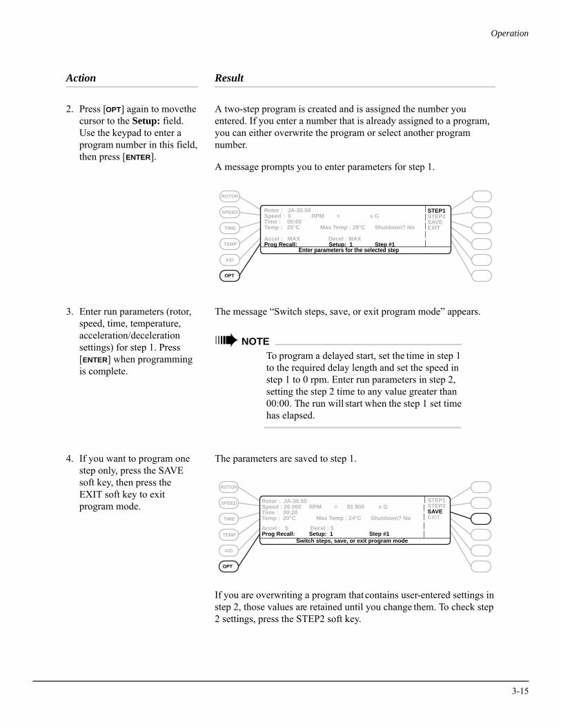
Operation
Action Result
2. Press [OPT] again to move the cursor to the Setup: field. Use the keypad to enter a program number in this field, then press [ENTER].
A two-step program is created and is assigned the number you entered. If you enter a number that is already assigned to a program, you can either overwrite the program or select another program number.
A message prompts you to enter parameters for step 1.
3. Enter run parameters (rotor, speed, time, temperature, acceleration/deceleration settings) for step 1. Press [ENTER] when programming is complete.
The message “Switch steps, save, or exit program mode” appears.
➠ NOTETo program a delayed start, set the time in step 1 to the required delay length and set the speed in step 1 to 0 rpm. Enter run parameters in step 2, setting the step 2 time to any value greater than 00:00. The run will start when the step 1 set time has elapsed.
4. If you want to program one step only, press the SAVE soft key, then press the EXIT soft key to exitprogram mode.
The parameters are saved to step 1.
If you are overwriting a program that contains user-entered settings in step 2, those values are retained until you change them. To check step 2 settings, press the STEP2 soft key.
Rotor : JA-30.50 Speed : 0 RPM = x GTime : 00:00Temp : 25°C Max Temp : 29°C Shutdown? No
STEP1STEP2SAVEEXIT
Accel : MAX Decel : MAXProg Recall: Setup: 1 Step #1
SPEED
TIME
TEMP
A/D
OPT
ROTOR
Enter parameters for the selected step
SPEED
TIME
TEMP
A/D
OPT
ROTOR
Accel : 5 Decel : 5Prog Recall: Setup: 1 Step #1
STEP1STEP2SAVEEXIT
Rotor : JA-30.50 Speed : 26 000 RPM = 81 800 x GTime : 00:20Temp : 20°C Max Temp : 24°C Shutdown? No
Switch steps, save, or exit program mode
3-15
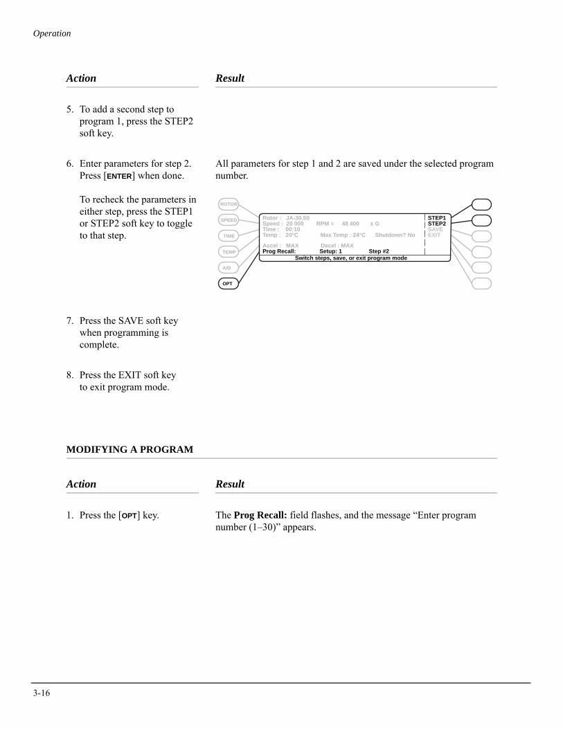
3-16
Operation
Action Result
5. To add a second step to program 1, press the STEP2 soft key.
6. Enter parameters for step 2. Press [ENTER] when done.
To recheck the parameters in either step, press the STEP1 or STEP2 soft key to toggle to that step.
All parameters for step 1 and 2 are saved under the selected program number.
7. Press the SAVE soft key when programming is complete.
8. Press the EXIT soft key to exit program mode.
MODIFYING A PROGRAM
Action Result
1. Press the [OPT] key. The Prog Recall: field flashes, and the message “Enter program number (1–30)” appears.
Rotor : JA-30.50 Speed : 20 000 RPM = 48 400 x GTime : 00:10 Temp : 20°C Max Temp : 24°C Shutdown? No
STEP1STEP2SAVEEXIT
Accel : MAX Decel : MAXProg Recall: Setup: 1 Step #2
SPEED
TIME
TEMP
A/D
OPT
ROTOR
Switch steps, save, or exit program mode
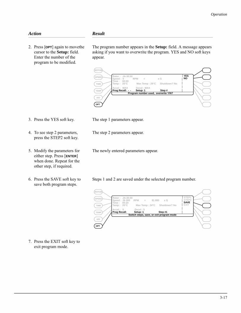
Operation
Action Result
2. Press [OPT] again to move the cursor to the Setup: field. Enter the number of the program to be modified.
The program number appears in the Setup: field. A message appears asking if you want to overwrite the program. YES and NO soft keys appear.
3. Press the YES soft key. The step 1 parameters appear.
4. To see step 2 parameters, press the STEP2 soft key.
The step 2 parameters appear.
5. Modify the parameters for either step. Press [ENTER] when done. Repeat for the other step, if required.
The newly entered parameters appear.
6. Press the SAVE soft key to save both program steps.
Steps 1 and 2 are saved under the selected program number.
7. Press the EXIT soft key toexit program mode.
SPEED
TIME
TEMP
A/D
OPT
ROTOR
Accel : MAX Decel : MAXProg Recall: - - Setup: 1 Step #
YESNO
Rotor : JA-30.50 Speed : 0 RPM = x GTime : 00:00Temp : 25°C Max Temp : 29°C Shutdown? No
Program number used, overwrite Y/N?
SPEED
TIME
TEMP
A/D
OPT
ROTOR
Accel : 5 Decel : 5Prog Recall: Setup: 1 Step #1
STEP1STEP2SAVEEXIT
Rotor : JA-30.50 Speed : 26 000 RPM = 81 800 x GTime : 00:20Temp : 20°C Max Temp : 24°C Shutdown? No
Switch steps, save, or exit program mode
3-17
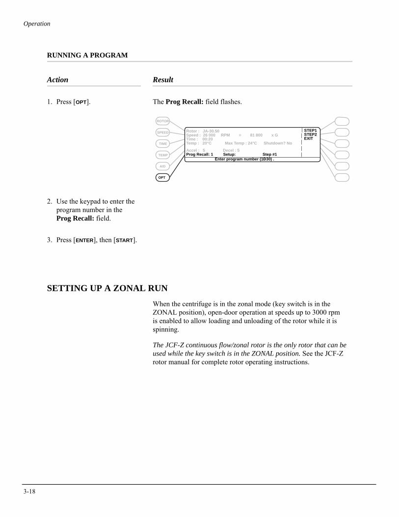
3-18
Operation
RUNNING A PROGRAM
Action Result
1. Press [OPT]. The Prog Recall: field flashes.
2. Use the keypad to enter theprogram number in the Prog Recall: field.
3. Press [ENTER], then [START].
SETTING UP A ZONAL RUN
When the centrifuge is in the zonal mode (key switch is in the ZONAL position), open-door operation at speeds up to 3000 rpm is enabled to allow loading and unloading of the rotor while it is spinning.
The JCF-Z continuous flow/zonal rotor is the only rotor that can be used while the key switch is in the ZONAL position. See the JCF-Z rotor manual for complete rotor operating instructions.
SPEED
TIME
TEMP
A/D
OPT
ROTOR
Accel : 5 Decel : 5Prog Recall: 1 Setup: Step #1
STEP1STEP2EXIT
Rotor : JA-30.50 Speed : 26 000 RPM = 81 800 x GTime : 00:20Temp : 20°C Max Temp : 24°C Shutdown? No
Enter program number (1Ð30) .
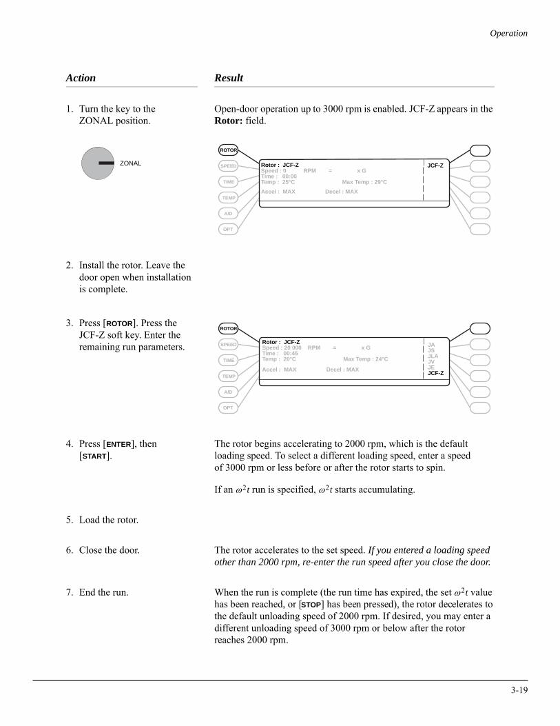
Operation
Action Result
1. Turn the key to the ZONAL position.
Open-door operation up to 3000 rpm is enabled. JCF-Z appears in the Rotor: field.
2. Install the rotor. Leave the door open when installation is complete.
3. Press [ROTOR]. Press theJCF-Z soft key. Enter theremaining run parameters.
4. Press [ENTER], then [START].
The rotor begins accelerating to 2000 rpm, which is the default loading speed. To select a different loading speed, enter a speed of 3000 rpm or less before or after the rotor starts to spin.
If an ω2t run is specified, ω2t starts accumulating.
5. Load the rotor.
6. Close the door. The rotor accelerates to the set speed. If you entered a loading speed other than 2000 rpm, re-enter the run speed after you close the door.
7. End the run. When the run is complete (the run time has expired, the set ω2t value has been reached, or [STOP] has been pressed), the rotor decelerates to the default unloading speed of 2000 rpm. If desired, you may enter a different unloading speed of 3000 rpm or below after the rotor reaches 2000 rpm.
ZONAL
Accel : MAX Decel : MAX
Rotor : JCF-ZSpeed : 0 RPM = x GTime : 00:00Temp : 25°C Max Temp : 29°C
JCF-ZSPEED
TIME
TEMP
A/D
OPT
ROTOR
Accel : MAX Decel : MAX
Rotor : JCF-ZSpeed : 20 000 RPM = x GTime : 00:45Temp : 20°C Max Temp : 24°C
SPEED
TIME
TEMP
A/D
OPT
ROTOR
JAJSJLAJVJEJCF-Z
3-19
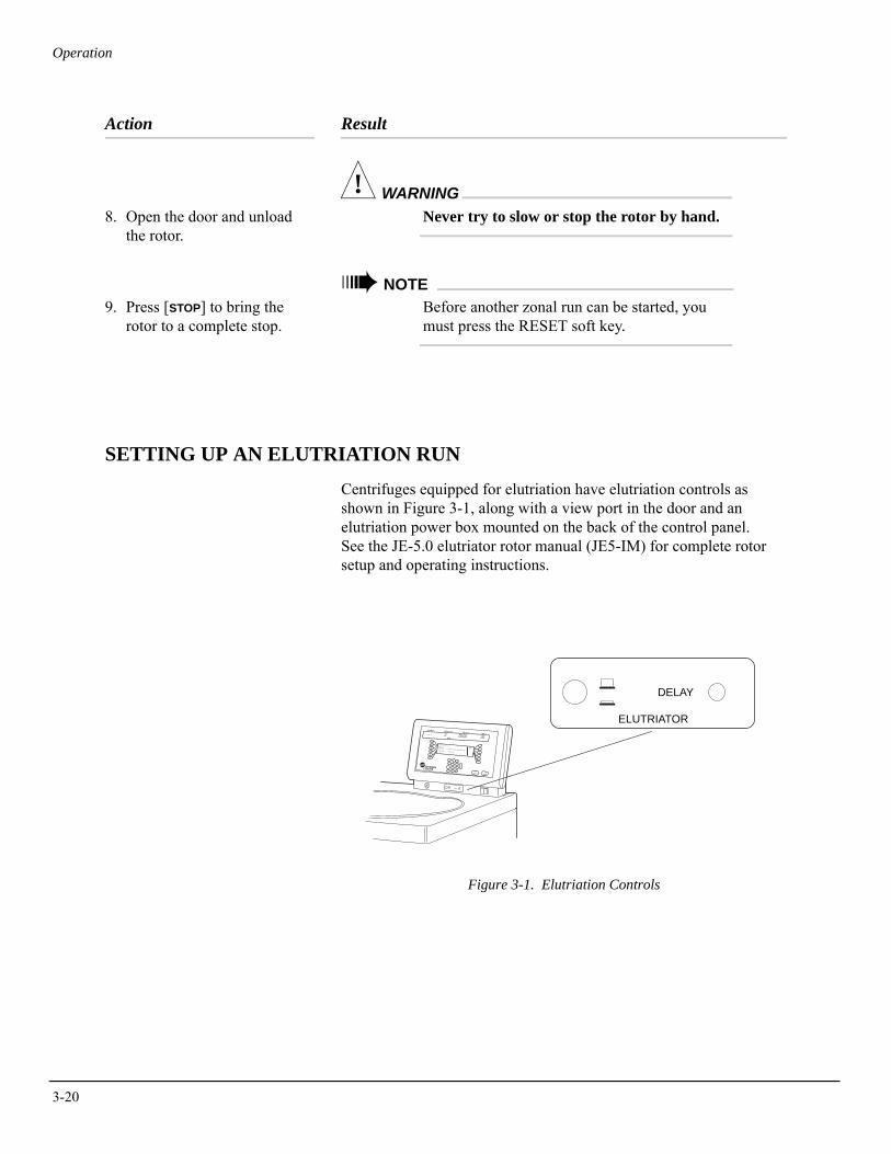
3-20
Operation
Action Result
8. Open the door and unloadthe rotor.
! WARNINGNever try to slow or stop the rotor by hand.
9. Press [STOP] to bring the rotor to a complete stop.
➠ NOTEBefore another zonal run can be started, you must press the RESET soft key.
SETTING UP AN ELUTRIATION RUN
Centrifuges equipped for elutriation have elutriation controls as shown in Figure 3-1, along with a view port in the door and an elutriation power box mounted on the back of the control panel. See the JE-5.0 elutriator rotor manual (JE5-IM) for complete rotor setup and operating instructions.
Figure 3-1. Elutriation Controls
DELAY
ELUTRIATOR
DELAY
ELUTRIATOR
START
ROTOR
SPEED
TIME
TEMP
A/D
OPT
ROTOR: JA-20
RPMRCF
TIME: 00:00TEMP: 25°C MAX TEMP : 29°C SHUTDOWN? YESACCEL: MAX DECEL: MAX
CE
3
6
9
2
+
5
8
1
0
4
7
ENTER
STOP
.TM
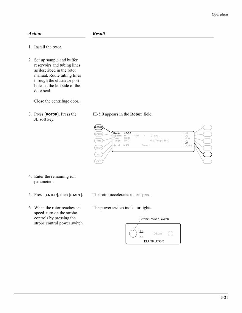
Operation
Action Result
1. Install the rotor.
2. Set up sample and buffer reservoirs and tubing lines as described in the rotor manual. Route tubing lines through the elutriator port holes at the left side of the door seal.
Close the centrifuge door.
3. Press [ROTOR]. Press the JE soft key.
JE-5.0 appears in the Rotor: field.
4. Enter the remaining run parameters.
5. Press [ENTER], then [START]. The rotor accelerates to set speed.
6. When the rotor reaches set speed, turn on the strobe controls by pressing the strobe control power switch.
The power switch indicator lights.
Rotor : JE-5.0Speed : 0 RPM = 0 x GTime : 00:00Temp : 25°C Max Temp : 29°C
JAJSJLAJVJEJCF-ZAccel : MAX Decel :
SPEED
TIME
TEMP
A/D
OPT
ROTOR
Strobe Power Switch
ELUTRIATOR
DELAY
3-21
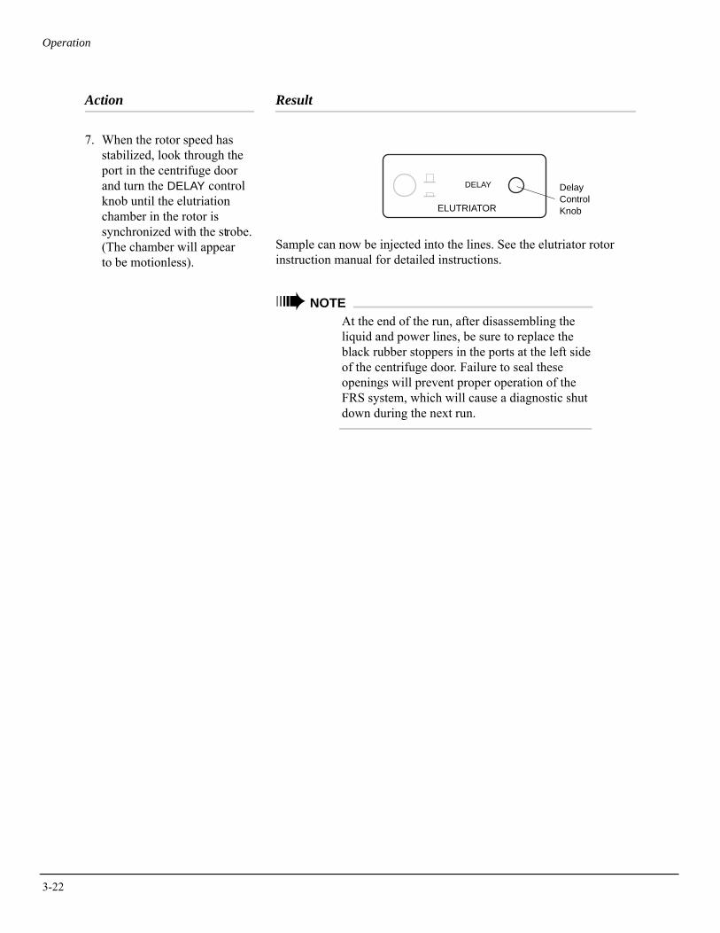
3-22
Operation
Action Result
7. When the rotor speed has stabilized, look through the port in the centrifuge door and turn the DELAY control knob until the elutriation chamber in the rotor is synchronized with the strobe. (The chamber will appear to be motionless).
Sample can now be injected into the lines. See the elutriator rotor instruction manual for detailed instructions.
➠ NOTEAt the end of the run, after disassembling the liquid and power lines, be sure to replace the black rubber stoppers in the ports at the left side of the centrifuge door. Failure to seal these openings will prevent proper operation of the FRS system, which will cause a diagnostic shut down during the next run.
DELAY DelayControlKnobELUTRIATOR
4Troubleshooting
This section lists possible malfunctions, along with probable causes and corrective actions. Maintenance procedures are given in Section 5. For any problems not covered here, contact Beckman Coulter Field Service (1-800-742-2345 in the United States) for assistance.
➠ NOTEIt is your responsibility to decontaminate the instrument, as well as any rotors and accessories, before requesting service by Beckman Coulter Field Service.
USER MESSAGES
User messages appear on the setup screen to communicate informa-tion about the instrument or to alert you to abnormal conditions that need attention.
• Help and informational messages caused by incorrect input or certain operating conditions can be cleared by pressing [CE] and following the instructions in the message.
• Diagnostic messages that result from abnormal operating condi-tions or equipment malfunction require troubleshooting. Refer to Table 4-1 to determine the nature of the condition and any recom-mended actions. If a problem persists after you have performed the recommended action, call your Beckman Coulter Field Service representative (in the United States, call 1-800-742-2345; outside the U.S., call your local Beckman Coulter office). To help the field service representative diagnose and correct the problem, try to gather as much information about the situation as you can, including:
4-1
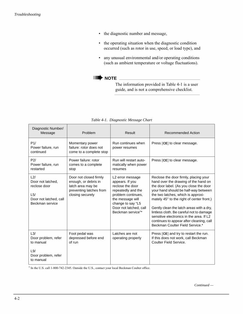
4-2
Troubleshooting
• the diagnostic number and message,
• the operating situation when the diagnostic condition occurred (such as rotor in use, speed, or load type), and
• any unusual environmental and/or operating conditions (such as ambient temperature or voltage fluctuations).
➠ NOTEThe information provided in Table 4-1 is a user guide, and is not a comprehensive checklist.
Table 4-1. Diagnostic Message Chart
* In the U.S. call 1-800-742-2345. Outside the U.S., contact your local Beckman Coulter office.
Diagnostic Number/Message Problem Result Recommended Action
P1/Power failure, run continued
Momentary power failure: rotor does not come to a complete stop
Run continues when power resumes
Press [CE] to clear message.
P2/Power failure, run restarted
Power failure: rotor comes to a complete stop
Run will restart auto-matically when power resumes
Press [CE] to clear message.
L2/Door not latched, reclose door
L5/Door not latched, call Beckman service
Door not closed firmly enough, or debris in latch area may be preventing latches from closing securely
L2 error message appears. If you reclose the door repeatedly and the problem continues, the message will change to say “L5 Door not latched, call Beckman service”*
Reclose the door firmly, placing your hand over the drawing of the hand on the door label. (As you close the door your hand should be half-way between the two latches, which is approxi-mately 45° to the right of center front.)
Gently clean the latch areas with a dry, lintless cloth. Be careful not to damage sensitive electronics in the area. If L2 continues to appear after cleaning, call Beckman Coulter Field Service.*
L3/ Door problem, refer to manual
L9/Door problem, refer to manual
Foot pedal was depressed before end of run
Latches are not operating properly
Press [CE] and try to restart the run.If this does not work, call Beckman Coulter Field Service.
Continued —
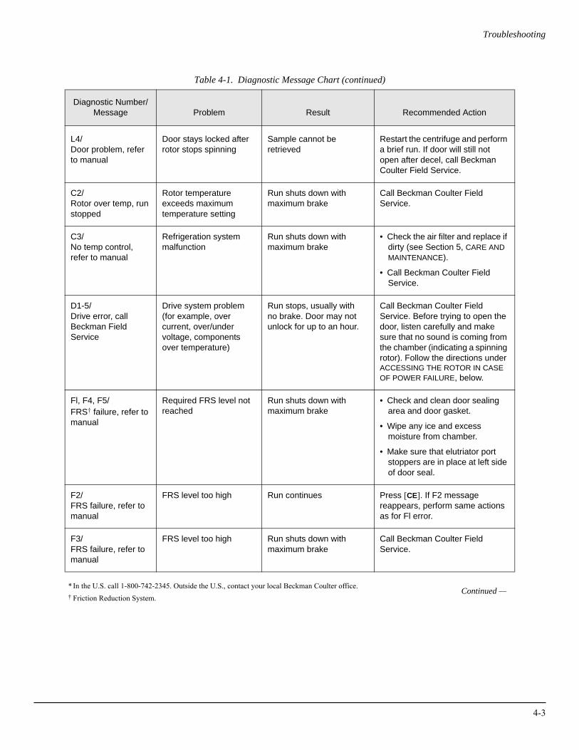
Troubleshooting
Table 4-1. Diagnostic Message Chart (continued)
* In the U.S. call 1-800-742-2345. Outside the U.S., contact your local Beckman Coulter office.† Friction Reduction System.
Diagnostic Number/Message Problem Result Recommended Action
L4/ Door problem, refer to manual
Door stays locked after rotor stops spinning
Sample cannot be retrieved
Restart the centrifuge and perform a brief run. If door will still not open after decel, call Beckman Coulter Field Service.
C2/ Rotor over temp, run stopped
Rotor temperature exceeds maximum temperature setting
Run shuts down with maximum brake
Call Beckman Coulter Field Service.
C3/ No temp control, refer to manual
Refrigeration system malfunction
Run shuts down with maximum brake
• Check the air filter and replace if dirty (see Section 5, CARE AND MAINTENANCE).
• Call Beckman Coulter Field Service.
D1-5/Drive error, call Beckman Field Service
Drive system problem (for example, over current, over/under voltage, components over temperature)
Run stops, usually with no brake. Door may not unlock for up to an hour.
Call Beckman Coulter Field Service. Before trying to open the door, listen carefully and make sure that no sound is coming from the chamber (indicating a spinning rotor). Follow the directions under ACCESSING THE ROTOR IN CASE OF POWER FAILURE, below.
Fl, F4, F5/ FRS† failure, refer to manual
Required FRS level not reached
Run shuts down with maximum brake
• Check and clean door sealing area and door gasket.
• Wipe any ice and excess moisture from chamber.
• Make sure that elutriator port stoppers are in place at left side of door seal.
F2/ FRS failure, refer to manual
FRS level too high Run continues Press [CE]. If F2 message reappears, perform same actions as for Fl error.
F3/ FRS failure, refer to manual
FRS level too high Run shuts down with maximum brake
Call Beckman Coulter Field Service.
Continued —
4-3
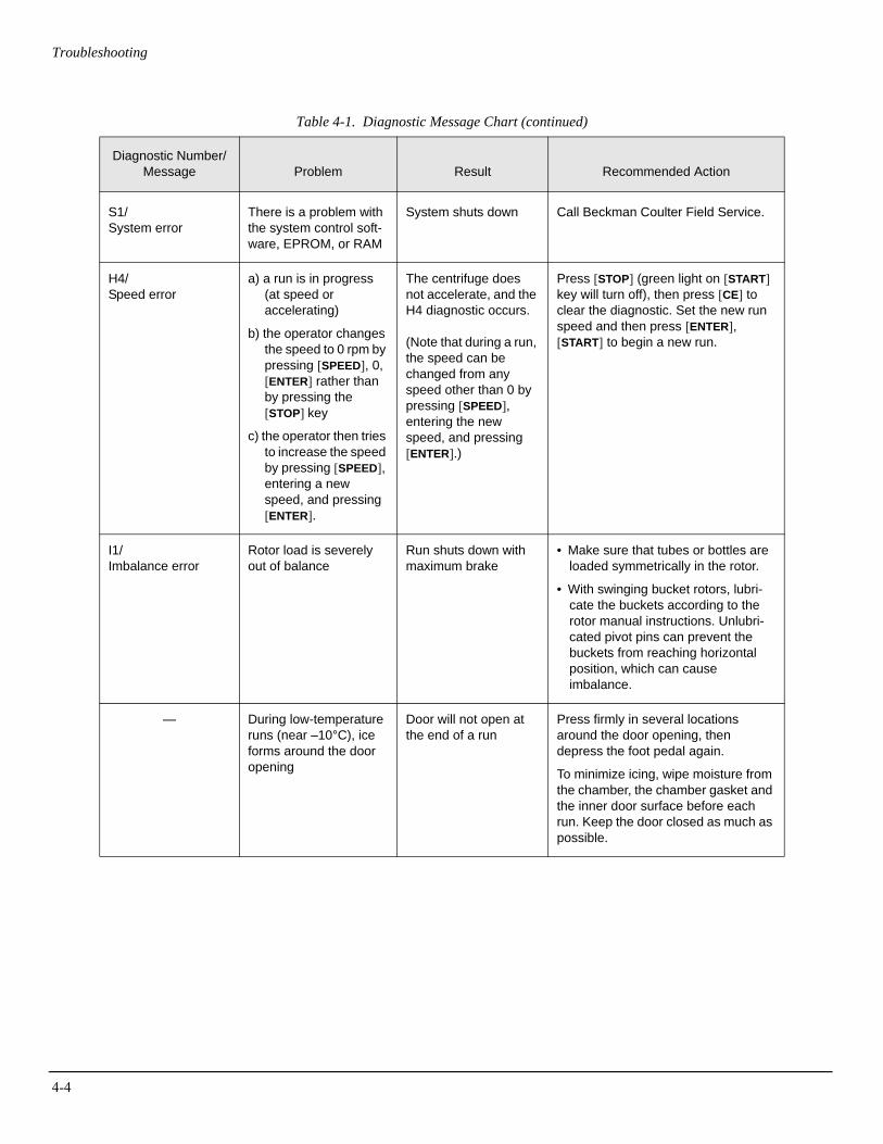
4-4
Troubleshooting
Table 4-1. Diagnostic Message Chart (continued)
Diagnostic Number/Message Problem Result Recommended Action
S1/System error
There is a problem with the system control soft-ware, EPROM, or RAM
System shuts down Call Beckman Coulter Field Service.
H4/Speed error
a) a run is in progress (at speed or accelerating)
b) the operator changes the speed to 0 rpm by pressing [SPEED], 0, [ENTER] rather than by pressing the [STOP] key
c) the operator then tries to increase the speed by pressing [SPEED], entering a new speed, and pressing [ENTER].
The centrifuge does not accelerate, and the H4 diagnostic occurs.
(Note that during a run, the speed can be changed from any speed other than 0 by pressing [SPEED], entering the new speed, and pressing [ENTER].)
Press [STOP] (green light on [START] key will turn off), then press [CE] to clear the diagnostic. Set the new run speed and then press [ENTER], [START] to begin a new run.
I1/Imbalance error
Rotor load is severely out of balance
Run shuts down with maximum brake
• Make sure that tubes or bottles are loaded symmetrically in the rotor.
• With swinging bucket rotors, lubri-cate the buckets according to the rotor manual instructions. Unlubri-cated pivot pins can prevent the buckets from reaching horizontal position, which can cause imbalance.
— During low-temperature runs (near –10°C), ice forms around the door opening
Door will not open at the end of a run
Press firmly in several locations around the door opening, then depress the foot pedal again.
To minimize icing, wipe moisture from the chamber, the chamber gasket and the inner door surface before each run. Keep the door closed as much as possible.
Troubleshooting
ACCESSING THE ROTOR IN CASE OF POWER FAILURE
WARNINGAny maintenance procedure requiring removal of a panel exposes the operator to the possibility of electrical shock and/or mechanical injury. Therefore, turn the power off (O) and disconnect the instrument from the main power source, and refer such main-tenance to qualified service personnel.
! WARNINGBefore performing this procedure, verify that the rotor is not spinning by listening carefully for any noise coming from the chamber. Proceed only if the instrument is quiet. Never attempt to override the door interlock system while the rotor is spinning.
If the facility power fails momentarily, the centrifuge will resume operation when the power is restored and the rotor will return to the set speed. In the event of an extended power failure, you may need to override the door-locking mechanism manually to remove the rotor and retrieve your sample.
To access the door-locking mechanism, you must remove the instru-ment front panel. Two latches secure the front panel in place; these latches are accessible through two holes at the upper right and left of the panel (see Figure 4-1).
Action Result
1. Turn the power switch to off (O) and unplug the power cord from the main source.
4-5
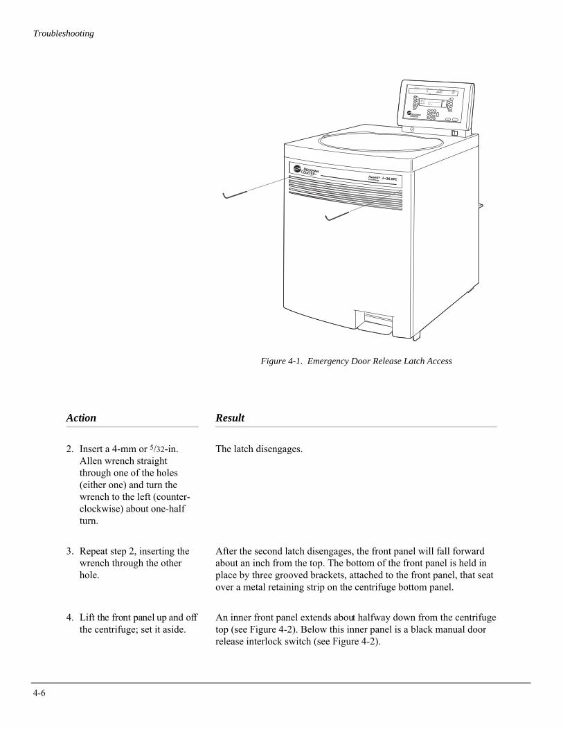
4-6
Troubleshooting
Figure 4-1. Emergency Door Release Latch Access
Action Result
2. Insert a 4-mm or 5/32-in. Allen wrench straight through one of the holes (either one) and turn the wrench to the left (counter-clockwise) about one-half turn.
The latch disengages.
3. Repeat step 2, inserting the wrench through the other hole.
After the second latch disengages, the front panel will fall forward about an inch from the top. The bottom of the front panel is held in place by three grooved brackets, attached to the front panel, that seat over a metal retaining strip on the centrifuge bottom panel.
4. Lift the front panel up and off the centrifuge; set it aside.
An inner front panel extends about halfway down from the centrifuge top (see Figure 4-2). Below this inner panel is a black manual door release interlock switch (see Figure 4-2).
START
ROTOR
SPEED
TIME
TEMP
A/D
OPT
ROTOR: JA-20
RPMRCF
TIME: 00:00TEMP: 25°C MAX TEMP : 29°C SHUTDOWN? YESACCEL: MAX DECEL: MAX
CE
3
6
9
2
+
5
8
1
0
4
7
ENTER
STOP
.
MADE IN U.S.A.
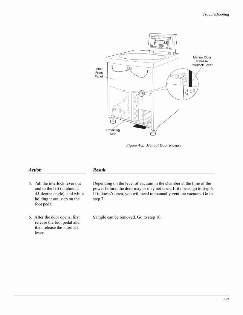
Troubleshooting
Figure 4-2. Manual Door Release
Action Result
5. Pull the interlock lever out and to the left (at about a 45-degree angle), and while holding it out, step on the foot pedal.
Depending on the level of vacuum in the chamber at the time of the power failure, the door may or may not open. If it opens, go to step 6. If it doesn’t open, you will need to manually vent the vacuum. Go to step 7.
6. After the door opens, first release the foot pedal and then release the interlock lever.
Sample can be removed. Go to step 10.
START
ROTOR ID SPEED TIME
RPM
TEMPRPM/RCF
ROTOR
SPEED
TIME
TEMP
A/D
OPT
ROTOR: JA-20
RPMRCF
TIME: 00:00TEMP: 25°C MAX TEMP : 29°C SHUTDOWN? YESACCEL: MAX DECEL: MAX
HR:MIN°C
CE
3
6
9
2
+
5
8
1
0
4
7
ENTER
STOP
.
RetainingStrip
Manual DoorRelease
Interlock LeverInnerFrontPanel
TM
4-7
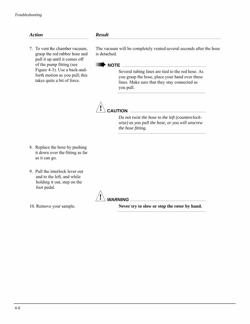
4-8
Troubleshooting
Action Result
7. To vent the chamber vacuum, grasp the red rubber hose and pull it up until it comes off of the pump fitting (see Figure 4-3). Use a back-and-forth motion as you pull; this takes quite a bit of force.
The vacuum will be completely vented several seconds after the hose is detached.
➠ NOTESeveral tubing lines are tied to the red hose. As you grasp the hose, place your hand over these lines. Make sure that they stay connected as you pull.
! CAUTIONDo not twist the hose to the left (counterclock-wise) as you pull the hose, or you will unscrew the hose fitting.
8. Replace the hose by pushing it down over the fitting as far as it can go.
9. Pull the interlock lever out and to the left, and while holding it out, step on the foot pedal.
10. Remove your sample.
! WARNINGNever try to slow or stop the rotor by hand.
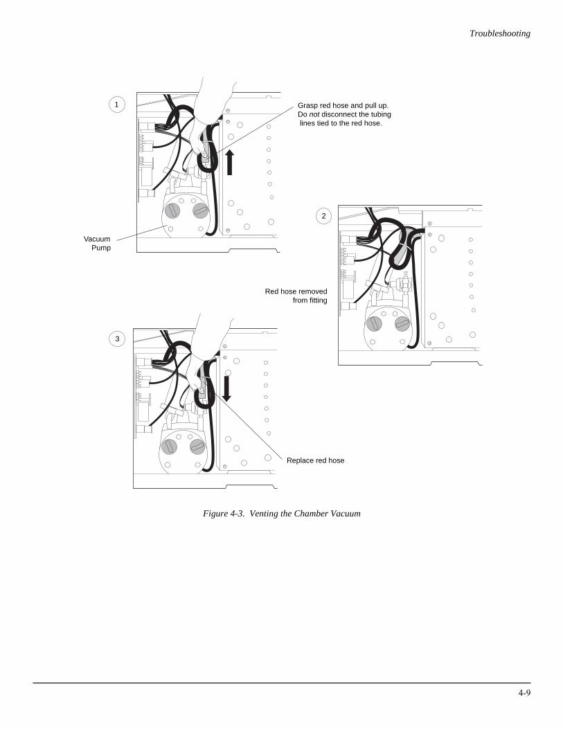
Troubleshooting
Figure 4-3. Venting the Chamber Vacuum
VacuumPump
Grasp red hose and pull up. Do not disconnect the tubing lines tied to the red hose.
Red hose removedfrom fitting
Replace red hose
1
2
3
4-9
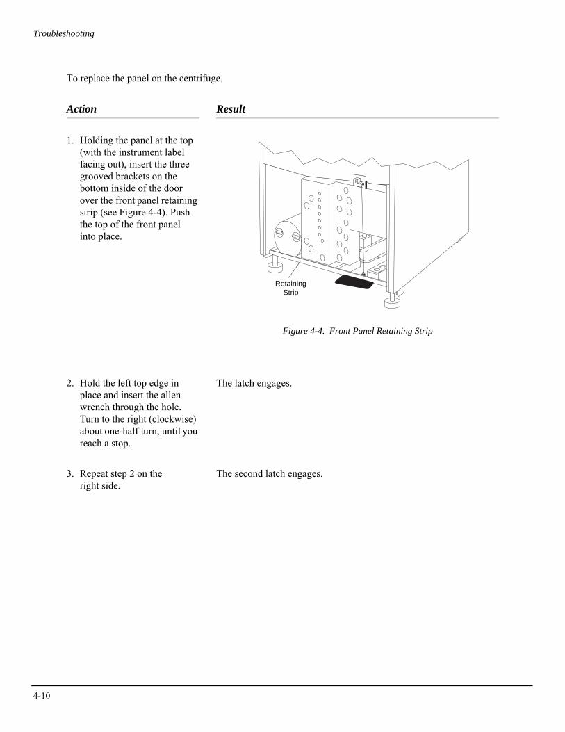
4-10
Troubleshooting
To replace the panel on the centrifuge,
Action Result
1. Holding the panel at the top (with the instrument label facing out), insert the three grooved brackets on the bottom inside of the door over the front panel retaining strip (see Figure 4-4). Push the top of the front panel into place.
Figure 4-4. Front Panel Retaining Strip
2. Hold the left top edge in place and insert the allen wrench through the hole. Turn to the right (clockwise) about one-half turn, until you reach a stop.
The latch engages.
3. Repeat step 2 on the right side.
The second latch engages.
RetainingStrip
Troubleshooting
JCF-Z ROTOR IDENTIFICATION
The rotor identification system can, under two specific conditions, misidentify the JCF-Z continuous flow/zonal rotor. Misidentification has occurred if a rotor name other than JCF-Z appears in the ROTOR display when the centrifuge door is closed. If the rotor is misidenti-fied, stop the run and follow one of the steps below.
➠ NOTEMisidentification can be prevented by returning your JCF-Z rotor to the Beckman Coulter factory in Palo Alto, California, to have magnets added to the rotor body. The magnets ensure correct rotor identification. Call Beckman Coulter Field Service1 for more information.
JCF-Z rotors manufactured after March, 1997, have factory-installed magnets.
• On the first few uses of a new JCF-Z rotor, or in an older JCF-Z rotor with newly replaced bearings, run the rotor from 0 to 5000 rpm and back to 0 rpm three times. This procedure will distribute lubricant around the bearings in the rotating seal assembly, reducing drag.
• In older JCF-Z rotors with bearings that have not been replaced recently, follow the same procedure as for a new JCF-Z rotor (perform three runs from 0 to 5000 rpm and back to 0 rpm) to ensure that the bearings are properly lubricated. If misidentifica-tion recurs after the third run, when the bearings are lubricated, this indicates that the bearings are worn and need to be replaced. Replace the bearings following the instructions in the JCF-Z manual (JCFZ-IM).
➠ NOTEIf the JCF-Z rotor is misidentified, the run speed will be limited to the maximum speed for the identified rotor. (The maximum speed for the JCF-Z rotor is 20 000 rpm.)
1 In the United States, call 1-800-742-2345. Outside the U.S., contact your local Beckman Coulter office.
4-11

5Care and Maintenance
This section describes routine care and maintenance procedures that you should perform regularly or as required. For maintenance not covered in this manual, contact Beckman Coulter Field Service.1 Refer to the applicable rotor manual and Rotors and Tubes for J Series Centrifuges (publication JR-IM) for instructions on the care of rotors and accessories.
➠ NOTEIt is your responsibility to decontaminate the instrument, as well as any rotors and accessories, before requesting service by Beckman Coulter Field Service.
WARNINGAny maintenance procedure or servicing of this equipment requiring removal of any covers can expose parts which involve the risk of electric shock or personal injury. Make sure that the power switch is off (O) and the centrifuge is disconnected from the main power source, and refer such servicing to qualified service personnel.
! WARNINGDo not use alcohol or other flammable substances in or near operating centrifuges.
1 In the U.S., call 1-800-742-2345. Outside the U.S., contact your local Beckman Coulter office.
5-1
5-2
Care and Maintenance
MAINTENANCE
Perform the following procedures regularly to ensure continued performance and long service life of the centrifuge.
• Inspect the centrifuge chamber for accumulations of sample, dust, or glass particles from broken sample tubes. Clean as required (see CLEANING, below).
• Check the air filter on the back panel for obstructions. Keep vents clear and clean.
• Wipe condensation out of the rotor chamber between runs with a sponge or clean cloth to prevent chamber icing.
• If chamber icing occurs, defrost the system and wipe moisture out of the chamber before use. To defrost the system, set the tempera-ture to 30°C for 20 minutes. (These are suggested settings which may be adjusted as appropriate for your laboratory conditions.)
➠ NOTEBefore using any cleaning or decontamination methods except those recommended by the manufacturer, users should check with the manufacturer that the proposed method will not damage the equipment.
CLEANING
Clean the centrifuge frequently. Always clean up spills when they occur to prevent corrosives or contaminants from drying on compo-nent surfaces.
• To prevent accumulations of sample, dust, and/or glass particles from broken sample tubes, keep the chamber clean and dry by frequent wiping with a cloth or paper towel. For thorough cleaning, wash the chamber using a mild detergent such as Beckman Solution 555™, diluted 10 to 1 with water. Rinse thoroughly and dry completely.
• Clean the centrifuge exterior surfaces by wiping with a cloth dampened with Solution 555, diluted 10 to 1 with water. Do not use acetone.
• Clean the drive hub regularly using Solution 555 (diluted 10 to 1 with water) and a soft brush. Rinse thoroughly and dry completely.
Care and Maintenance
Tube Breakage
If a glass tube breaks, and all the glass is not contained in the bucket or rotor, be sure to thoroughly clean the chamber.
! WARNINGBe careful when examining or cleaning the chamber and chamber gasket, as sharp glass fragments may be embedded in their surfaces.
• Examine the chamber gasket to make sure that no glass particles are retained in it. Carefully remove any glass particles that may remain.
• Carefully wipe away any glass particles that remain in the chamber.
DECONTAMINATION
If the centrifuge and/or accessories are contaminated with radioactive or pathogenic solutions, perform all appropriate safety and decontam-ination procedures. Refer to Appendix A in Rotors and Tubes or publication IN-175 to be sure the decontamination method will not damage any part of the instrument.
STERILIZATION AND DISINFECTION
The centrifuge is finished with urethane paint. Ethanol (70%)2 may be used on this surface. See Appendix A in Rotors and Tubes or publication IN-175 for chemical resistances of centrifuge and accessory materials.
While Beckman Coulter has tested ethanol (70%) and found that it does not damage the centrifuge, no guarantee of sterility or disinfec-tion is expressed or implied. When sterilization or disinfection is a concern, consult your laboratory safety officer regarding proper methods to use.
2 Flammability hazard. Do not use in or near operating centrifuges.
5-3
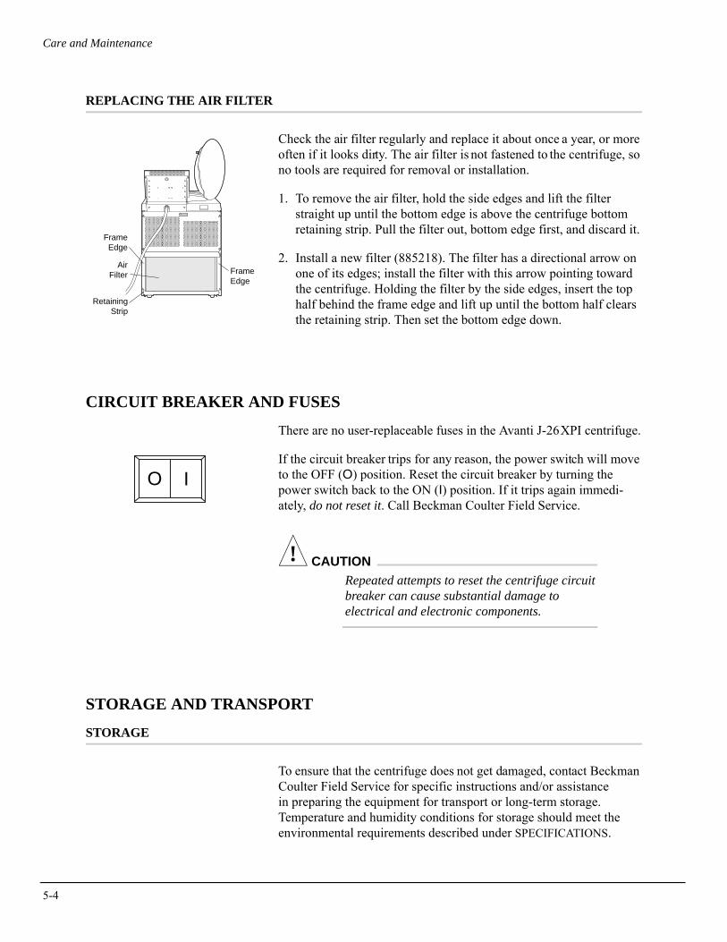
5-4
Care and Maintenance
REPLACING THE AIR FILTER
Check the air filter regularly and replace it about once a year, or more often if it looks dirty. The air filter is not fastened to the centrifuge, so no tools are required for removal or installation.
1. To remove the air filter, hold the side edges and lift the filter straight up until the bottom edge is above the centrifuge bottom retaining strip. Pull the filter out, bottom edge first, and discard it.
2. Install a new filter (885218). The filter has a directional arrow on one of its edges; install the filter with this arrow pointing toward the centrifuge. Holding the filter by the side edges, insert the top half behind the frame edge and lift up until the bottom half clears the retaining strip. Then set the bottom edge down.
CIRCUIT BREAKER AND FUSES
There are no user-replaceable fuses in the Avanti J-26XPI centrifuge.
If the circuit breaker trips for any reason, the power switch will move to the OFF (O) position. Reset the circuit breaker by turning the power switch back to the ON (I) position. If it trips again immedi-ately, do not reset it. Call Beckman Coulter Field Service.
! CAUTIONRepeated attempts to reset the centrifuge circuit breaker can cause substantial damage to electrical and electronic components.
STORAGE AND TRANSPORT
STORAGE
To ensure that the centrifuge does not get damaged, contact Beckman Coulter Field Service for specific instructions and/or assistance in preparing the equipment for transport or long-term storage. Temperature and humidity conditions for storage should meet the environmental requirements described under SPECIFICATIONS.
FrameEdge
FrameEdge
AirFilter
RetainingStrip
IO
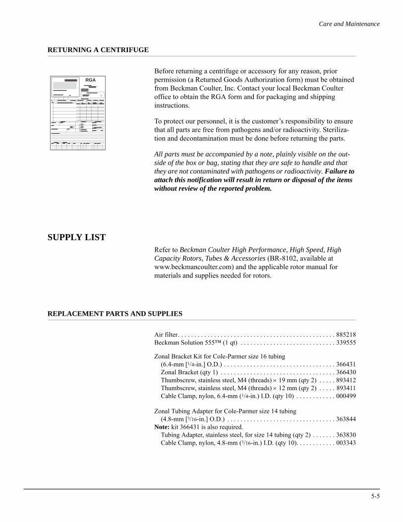
Care and Maintenance
RETURNING A CENTRIFUGE
Before returning a centrifuge or accessory for any reason, prior permission (a Returned Goods Authorization form) must be obtained from Beckman Coulter, Inc. Contact your local Beckman Coulter office to obtain the RGA form and for packaging and shipping instructions.
To protect our personnel, it is the customer’s responsibility to ensure that all parts are free from pathogens and/or radioactivity. Steriliza-tion and decontamination must be done before returning the parts.
All parts must be accompanied by a note, plainly visible on the out-side of the box or bag, stating that they are safe to handle and that they are not contaminated with pathogens or radioactivity. Failure to attach this notification will result in return or disposal of the items without review of the reported problem.
SUPPLY LISTRefer to Beckman Coulter High Performance, High Speed, High Capacity Rotors, Tubes & Accessories (BR-8102, available at www.beckmancoulter.com) and the applicable rotor manual for materials and supplies needed for rotors.
REPLACEMENT PARTS AND SUPPLIES
Air filter. . . . . . . . . . . . . . . . . . . . . . . . . . . . . . . . . . . . . . . . . . . . . . . . 885218Beckman Solution 555™ (1 qt) . . . . . . . . . . . . . . . . . . . . . . . . . . . . . 339555
Zonal Bracket Kit for Cole-Parmer size 16 tubing (6.4-mm [1/4-in.] O.D.) . . . . . . . . . . . . . . . . . . . . . . . . . . . . . . . . . . 366431Zonal Bracket (qty 1) . . . . . . . . . . . . . . . . . . . . . . . . . . . . . . . . . . . 366430Thumbscrew, stainless steel, M4 (threads) × 19 mm (qty 2) . . . . . 893412Thumbscrew, stainless steel, M4 (threads) × 12 mm (qty 2) . . . . . 893411Cable Clamp, nylon, 6.4-mm (1/4-in.) I.D. (qty 10) . . . . . . . . . . . . 000499
Zonal Tubing Adapter for Cole-Parmer size 14 tubing(4.8-mm [3/16-in.] O.D.) . . . . . . . . . . . . . . . . . . . . . . . . . . . . . . . . . 363844
Note: kit 366431 is also required.Tubing Adapter, stainless steel, for size 14 tubing (qty 2) . . . . . . . 363830Cable Clamp, nylon, 4.8-mm (3/16-in.) I.D. (qty 10). . . . . . . . . . . . 003343
RGA
5-5

5-6
Care and Maintenance
Zonal Tubing Adapter for Cole-Parmer size 15 tubing(9.6-mm [3/8-in.] O.D.) . . . . . . . . . . . . . . . . . . . . . . . . . . . . . . . . . . 363845
Note: kit 366431 is also required.Tubing Adapter, stainless steel, for size 15 tubing (qty 2) . . . . . . . 363831Cable Clamp, nylon, 9.6-mm (3/8-in.) I.D. (qty 10) . . . . . . . . . . . . 000596
Elutriation upgrade kit. . . . . . . . . . . . . . . . . . . . . . . . . . . . . . . . . . . . . 366563
APPENDIXTemperature Calibration
Procedure
The Avanti J-26XPI centrifuge specification for temperature control is ±2°C of the set temperature. That means that your sample will stay within 2°C of set temperature at all times, after rotor and system equilibration, described below. (During transient conditions, such as acceleration and deceleration, the rotor temperatures may be outside this range.) The following procedure is provided for those cases in which temperature control within ±1°C is required.
In this procedure, you will measure the temperature of your sample after equilibrating the rotor temperature for a minimum of 1 hour. Based on the test results, you can then adjust the centrifuge tempera-ture setting to bring your sample as close as possible to the required temperature.
1. For runs at other than ambient temperature, precool or prewarm the rotor and test samples to the required temperature. The length of precooling/prewarming time depends on how different the rotor starting temperature is from the required run temperature.
2. Install the rotor with adapters, if applicable, and tubes or bottles filled with sample buffer or water (if above 2°C).
3. Set the speed to 2000 rpm, the time to HOLD, and the temperature to the required run temperature. Start the run.
4. After 30 minutes, set the required run speed, and allow the system to run for at least 1 hour.
➠ NOTEThe system must run for at least 1 hour before the temperature of the buffer or water is measured. The length of time required for equil-ibration depends on the rotor and centrifuge starting temperatures and the ambient room temperature.
A-1
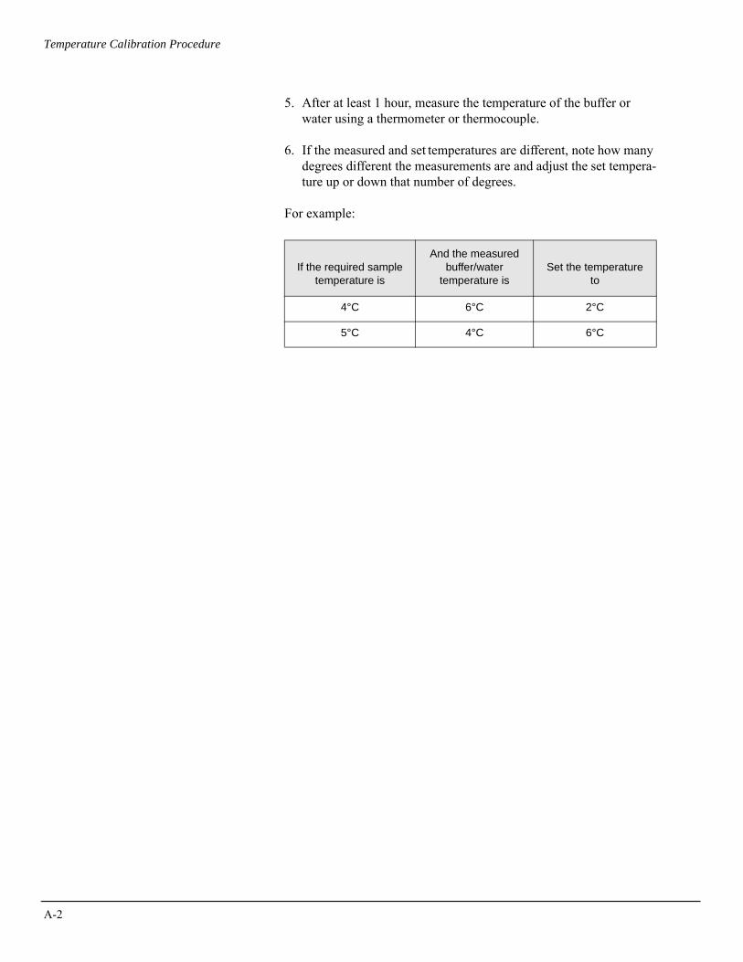
A-2
Temperature Calibration Procedure
5. After at least 1 hour, measure the temperature of the buffer or water using a thermometer or thermocouple.
6. If the measured and set temperatures are different, note how many degrees different the measurements are and adjust the set tempera-ture up or down that number of degrees.
For example:
If the required sample temperature is
And the measured buffer/water
temperature isSet the temperature
to
4°C 6°C 2°C
5°C 4°C 6°C
AVANTI® J SERIES CENTRIFUGE WARRANTY
Subject to th e exceptions and upon the conditions specifiedbelow Beckman Coulter agrees to correct either by repair, or,at i ts el ection, by repl acement, any defects of material orworkmanship which develop within one (1) year (3 years forthe drive motor) after delivery of the Avanti® J Series Centri-fuge centrifuge (the p roduct), to the original buyer byBeckman Coulter or by an aut horized representative, pro-vided that investigation an d factory inspection by BeckmanCoulter disclose s tha t suc h defect developed un der n ormaland proper use.
Some components and accesso ries by their nature are notintended to and will not function for as long as one (1) year. Ifany such component or accessory fails to give reasonable ser-vice for a reasonable period of time, Beckman Coulter willrepair or, at its election, replace such component or accessory.What const itutes either rea sonable se rvice and a reasonableperiod o f time shall be dete rmined s olely by Be ckmanCoulter.
REPLACEMENT
Any pro duct claimed to be de fective must , if reque sted byBeckman Coulter, be r eturned to the facto ry, transportationcharges prepaid, and will be returned to Buyer with the trans-portation charges collect unless the product is found to b edefective, in which case Beckman Coulter will pay all trans-portation charges.
Beckman Coulter makes no wa rranty concerning products oraccessories not manufactured by it. In the event of f ailure ofany such produ ct or accessory, Beckman C oulter will givereasonable assistance to th e Buyer in obtaining from therespective manufacturer whatever adjustment is reasonable inlight of the manufacturer’s own warranty.
CONDITIONS
Beckman Coulter shall be released from all obligations underall warranties, either expresse d or implied, if the productcovered hereby is repaired or modified by persons other thanits own au thorized service pers onnel, unless such repair byothers is made with the written consent of Beckman Coulter,or unless such repair in the sole opinion of Beckman Coulteris minor, or unless such modifications is merely the installa-tion of a new Beckman Coulter plug-in componen t for suchproduct.
DISCLAIMER
IT IS EXP RESSLY AGREED TH AT THE ABOVE WAR-RANTY SHALL BE IN LIEU OF ALL WARRANTIES OFFITNESS AND OF THE WARRANTY OF MERCHANT-ABILITY AND THAT BECKMAN COU LTER, INC.SHALL HAVE NO LIABILITY FOR SPECIA L OR CON-SEQUENTIAL DAMAGES OF ANY KIND WHA TSO-EVER ARISING OUT O F TH E MA NUFACTURE, USE,SALE, HAND LING, REP AIR, MA INTENANCE, ORREPLACEMENT OF THE PRODUCT.

Beckman Coulter, Inc. • 250 S. Kraemer Blvd. • Brea, California 92821Sales and Service: 1-800-742-2345 • Internet: www.beckmancoulter.com
©2009 Beckman Coulter, Inc.All rights reserved