Artigo COBEM 2009 VFinal
10
Proceedings of COBEM 2009 20th International Congress of Mechanical Engineering Copyright © 2009 by ABCM November 15-20, 2009, Gramado, RS, Brazil NUMERICAL SIMULATION OF CRACK PROPAGATION IN A DEGRADED MATERIAL UNDER ENVIRONMENTAL EFFECTS Jorge Palma Carrasco, [email protected] PhD Course in Science and Materials Engineering, Federal University of Campina Grande, C. Grande, PB – Brazil. José Maria Andrade Barbosa, [email protected] Department of Mechanical Engineering, Federal University of Pernambuco, Recife, PE – Brazil. Antonio Almeida Silva, [email protected] Department of Mechanical Engineering, Federal University of Campina Grande, C. Grande, PB – Brazil. Abstract. A numerical model based on the synthesis of Fracture Mechanics and Continuum Damage Mechanics is presented to treat the crack propagation problem in elastic regime, under a mechanical action and an environmental action. The environmental action is characterized by the hydrogen atoms presence in the lattice, which reduces the fracture toughness of many metals and metallic alloys. The crack is loaded in the tensile opening mode, in plane strain state and only two damage types are considered: a mechanical damage produced by a static load and a non- mechanical damage produced by the hydrogen diffusion of the mouth to the crack tip. The crack propagation is considered as the result of the interaction between the balance of forces and the global energy in the crack body-load system and the process of damage accumulation. The equations that describe the evolution of the v ariables at the crack tip form a non-lineal system of ordinary differential equations that is calculated by means of the 4th order Runge-Kutta method. The obtained results, for different concentration conditions, show the influence of the hydrogen concentration in the decrease of the time of growth and crack propagation, what keeps good correlation and consistency with macroscopic observations of the hydrogen embrittlement phenomenon. Additionally, the behavior of the curve of evolution of the stress intensity factor with the time, shows a similar behavior to the one reported in the scientific literature, allowing a better understanding of the process of beginning and crack propagation in aggressive environments, also demonstrating, the validity of the adopted model. Keywords : Continuum Damage Mechanics, Hydrogen Embrittlement, Cracks Propagation. 1. INTRODUCTION The non lineal response of the solids, observed in the macro-scale, is a manifestation of irreversible processes that happen in its micro-structure, some of which are originated in micro-defects that constitute the initial damage of the material. Depending on the environmental conditions and due to the existence of mechanical loads, even if the global response of the material stays inside in the limits of the elastic regime, the initial damage can develop taking to the formation and growth of microcracks. Environmental factors as the wet air, the seawater and other active media, frequently intensify the beginning and cracks propagation under static or cyclical mechanical loadings. Additionally, an important number of phenomena is related with those processes, showing a very important influence in the decrease of the fracture and fatigue toughness. A typical phenomenon is the hydrogen embrittlement that changes the mechanical properties of the metals and metallic alloys, with effects in the decrease of the fracture toughness and in the acceleration of the crack growth (Bolotin, 1999). The free hydrogen induce structural fails related with the stress corrosion cracking and corrosion fatigue; however, exists additional degradation phenomena, as the voids nucleation and bubbles formation product of the hydrogen diffusion, that can be qualified as microdamage processes and, from a phenomenological point of view, described as the damage produced by purely mechanical actions. Here, the term hydrogen embrittlement it is conditional and it includes a quantity of different mechanisms associated with the hydrogen diffusion in metals and metallic alloys. After the first model proposed by Kachanov, an impressive research activity was realized for the development of viable models for the description of the damage in a great amount of materials as the steel (Celentano & Chaboche, 2007), composites (Maimí, 2006) and others, with the purpose of solving a wide range of connected problems with the degradation of the material properties, such as thermal and inertial effects (Barbosa, 1998), and environmental factors (Duda et al ., 2007a; Barbosa et al., 2007). Recently, Duda et al . (2007b) formulated a one-dimensional model in the context of the continuum mechanics to simulate deformation, degradation and solute diffusion in elastic solids. In this article is presented the numerical model proposed by Bolotin & Shipkov (2001), previously used in the numerical simulation of stress corrosion cracking and fatigue corrosion problems, to simulate the crack propagation problem under the effect of a mechanical action defined by a static loading and a non-corrosive environmental action defined by the hydrogen presence in the lattice. The crack in a material body of high strength steel is loaded in the tensile opening mode, in plane strain state and only two damage types are considered: a mechanical damage produced by a static load and a non-mechanical damage produced b y the hydrogen. T he process is developed in elastic regime.
Transcript of Artigo COBEM 2009 VFinal
8/12/2019 Artigo COBEM 2009 VFinal
http://slidepdf.com/reader/full/artigo-cobem-2009-vfinal 1/10
Proceedings of COBEM 2009 20th International Congress of Mechanical EngineeringCopyright © 2009 by ABCM November 15-20, 2009, Gramado, RS, Brazil
NUMERICAL SIMULATION OF CRACK PROPAGATION IN A
DEGRADED MATERIAL UNDER ENVIRONMENTAL EFFECTS
Jorge Palma Carrasco, [email protected]
PhD Course in Science and Materials Engineering, Federal University of Campina Grande, C. Grande, PB – Brazil.José Maria Andrade Barbosa, [email protected]
Department of Mechanical Engineering, Federal University of Pernambuco, Recife, PE – Brazil.
Antonio Almeida Silva, [email protected]
Department of Mechanical Engineering, Federal University of Campina Grande, C. Grande, PB – Brazil.
Abstract. A numerical model based on the synthesis of Fracture Mechanics and Continuum Damage Mechanics is
presented to treat the crack propagation problem in elastic regime, under a mechanical action and an environmental
action. The environmental action is characterized by the hydrogen atoms presence in the lattice, which reduces the
fracture toughness of many metals and metallic alloys. The crack is loaded in the tensile opening mode, in plane strain
state and only two damage types are considered: a mechanical damage produced by a static load and a non-
mechanical damage produced by the hydrogen diffusion of the mouth to the crack tip. The crack propagation is
considered as the result of the interaction between the balance of forces and the global energy in the crack body-load system and the process of damage accumulation. The equations that describe the evolution of the variables at the crack
tip form a non-lineal system of ordinary differential equations that is calculated by means of the 4th order Runge-Kutta
method. The obtained results, for different concentration conditions, show the influence of the hydrogen concentration
in the decrease of the time of growth and crack propagation, what keeps good correlation and consistency with
macroscopic observations of the hydrogen embrittlement phenomenon. Additionally, the behavior of the curve of
evolution of the stress intensity factor with the time, shows a similar behavior to the one reported in the scientific
literature, allowing a better understanding of the process of beginning and crack propagation in aggressive
environments, also demonstrating, the validity of the adopted model.
Keywords : Continuum Damage Mechanics, Hydrogen Embrittlement, Cracks Propagation.
1. INTRODUCTION
The non lineal response of the solids, observed in the macro-scale, is a manifestation of irreversible processes that
happen in its micro-structure, some of which are originated in micro-defects that constitute the initial damage of thematerial. Depending on the environmental conditions and due to the existence of mechanical loads, even if the global
response of the material stays inside in the limits of the elastic regime, the initial damage can develop taking to the
formation and growth of microcracks. Environmental factors as the wet air, the seawater and other active media,
frequently intensify the beginning and cracks propagation under static or cyclical mechanical loadings. Additionally, an
important number of phenomena is related with those processes, showing a very important influence in the decrease of
the fracture and fatigue toughness. A typical phenomenon is the hydrogen embrittlement that changes the mechanical
properties of the metals and metallic alloys, with effects in the decrease of the fracture toughness and in the acceleration
of the crack growth (Bolotin, 1999).The free hydrogen induce structural fails related with the stress corrosion cracking and corrosion fatigue; however,
exists additional degradation phenomena, as the voids nucleation and bubbles formation product of the hydrogen
diffusion, that can be qualified as microdamage processes and, from a phenomenological point of view, described as the
damage produced by purely mechanical actions. Here, the term hydrogen embrittlement it is conditional and it includesa quantity of different mechanisms associated with the hydrogen diffusion in metals and metallic alloys.
After the first model proposed by Kachanov, an impressive research activity was realized for the development of
viable models for the description of the damage in a great amount of materials as the steel (Celentano & Chaboche,
2007), composites (Maimí, 2006) and others, with the purpose of solving a wide range of connected problems with the
degradation of the material properties, such as thermal and inertial effects (Barbosa, 1998), and environmental factors
(Duda et al ., 2007a; Barbosa et al., 2007). Recently, Duda et al . (2007b) formulated a one-dimensional model in the
context of the continuum mechanics to simulate deformation, degradation and solute diffusion in elastic solids.
In this article is presented the numerical model proposed by Bolotin & Shipkov (2001), previously used in thenumerical simulation of stress corrosion cracking and fatigue corrosion problems, to simulate the crack propagation
problem under the effect of a mechanical action defined by a static loading and a non-corrosive environmental action
defined by the hydrogen presence in the lattice. The crack in a material body of high strength steel is loaded in the
tensile opening mode, in plane strain state and only two damage types are considered: a mechanical damage produced by a static load and a non-mechanical damage produced by the hydrogen. The process is developed in elastic regime.
8/12/2019 Artigo COBEM 2009 VFinal
http://slidepdf.com/reader/full/artigo-cobem-2009-vfinal 2/10
Proceedings of COBEM 2009 20th International Congress of Mechanical EngineeringCopyright © 2009 by ABCM November 15-20, 2009, Gramado, RS, Brazil
2. MODEL OF BEGINNING AND CRACK GROWTH IN AGGRESSIVE ENVIRONMENTS
In this model, based in a synthesis of the Fracture Mechanics and of the Continuum Damage Mechanics, the crack
propagation is considered as the result of the interactions between the conditions of stability of the crack body as a
mechanical system and the process of damage accumulation. The model includes the kinetic equations for the
accumulation of each damage type, the equation that describes the conditions for the evolution of the crack tip and theequation that describes the influence of the damage accumulation process on the generalized resistance forces.
Will be presented the general theory for the propagation of fatigue cracks developed by Bolotin (1996) and
additionally, will be considered a mass transfer model. Their joining with the kinetic equations of damage
accumulation, associated to the equilibrium conditions, stability and crack propagation, will make possible the
modeling of the growth of a crack submitted to a static load under the effect of the hydrogen.
2.1. Cracked body mechanics
A cracked body submitted to a loading and the action of the environment is a special type of mechanical system,
whose state is described by a group of L-coordinate (Lagrangian) that describe the displacements field in the body and
another of G-coordinate (Griffithian) that describe the sharpening, size and position of the cracks. The changes of the
G-coordinate are denominated G-variation and represented for δa j.
The states of the crack body-loadings system can be classified with regard to the equilibrium and to the stability.The states in what the virtual work is negative for all δa j > 0 are nominated sub-equilibrium states. The states in that
exists some variation-G where the virtual work is zero and in the remaining the virtual work is negative, are nominated
equilibrium states; the sub-equilibrium state is also an equilibrium state from the point of view of the classic mechanics.
If at least for one of the variations the virtual work is positive, it is said that the system is in a non-equilibrium state.The stability conditions can also be expressed in terms of the virtual work. The sub-equilibrium states evidently are
stable, because additional amounts of energy are necessary to change the state of the system for any neighboring state
and those sources of energy don't exist inside of the system. The non-equilibrium states cannot be noticed as
equilibrium units and therefore, they are unstable. The equilibrium states can be stables, neutrals or unstables.
The stable equilibrium state is the most important in the theory of the fracture and fatigue, because it is the typical
case of the slow and stable propagation of the crack. A crack will propagate in a stable way when for some G-
coordinate, δGW = 0 and δG(δGW ) < 0 and still, when the condition δGW < 0 are satisfied for the other.
In terms of generalized driving and resistance forces, the virtual work of the G-variation can be represented for:
m
j
m
j
j j j jG aaGW
1 1
(1)
where δa j are the G-variations. The generalized driving and resistance forces are G j and Γ j respectively. In terms of
those forces, the crack won't grow while the condition G j < Γ j be respected. Their growth will begin when G j = Γ j and itwill turn unstable when for some δak , Gk > Γk , happening finally, the fracture of the component. These conditions are
valid to model the crack growth and of the final fracture for a static loading including the effect of an environmental
phenomenon, as the hydrogen embrittlement.
2.2. Hydrogen assisted damage
To model the process of damage accumulation in hydrogen assisted conditions, Bolotin (1999) and Bolotin &Shipkov (2001) uses the simplest, scalar model of damage of Kachanov (1986) and Rabotnov (1979) that characterize
the dispersed damage with the scalar field ω=( x,t ) that is function of the coordinates, of the time, of the number of
cycles and of other temporary variables. It is zero in the case where doesn't exist damage and equal to the unit in the
case where the material is completely damaged.
Instead of using a simple quantification for the damage, they are introduced a special measure for each damage type
and the correspondent kinetic equation that governs its evolution in the time. Same when only actions mechanics are
considered, it is differentiated the measures of the damage caused by the static loading of the damage due to other
mechanical loadings, as the cyclical. The damage caused by an environmental agent's diffusion is differentiated also of
the damage produced by a corrosion process. Therefore, the damage field introduced symbolically for ω=( x,t ), does it pass to be represented by a set of scalar damage fields, ω 1( x,t ), …, ω n( x,t ).
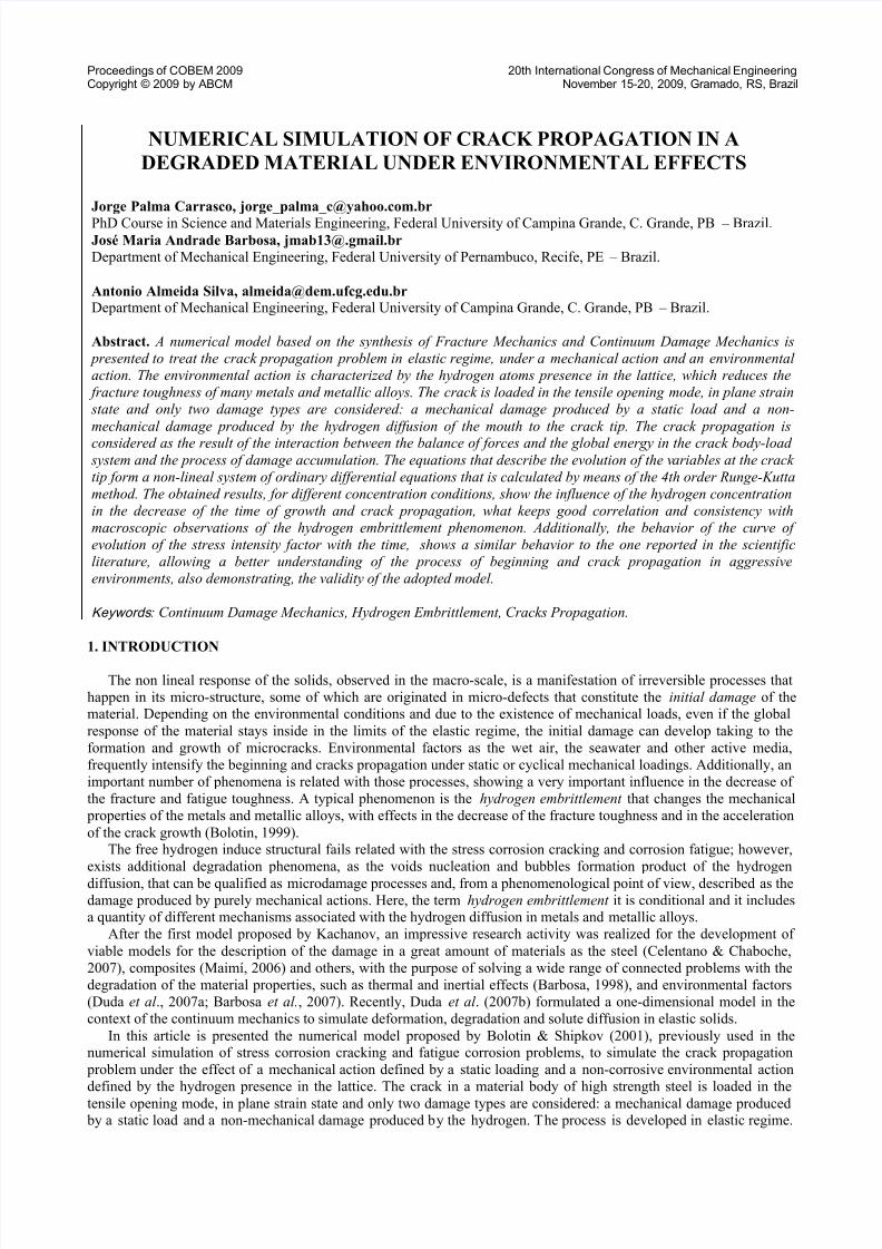
The disperse damage produced by a static loading in the mode I, ω s, and the disperse damage caused by the
hydrogen diffusion, ωh, are shown in Fig. 1. The hydrogen damage is a component that it is added to the total damage
magnitude and that it only depends on the hydrogen concentration at the crack tip.
8/12/2019 Artigo COBEM 2009 VFinal
http://slidepdf.com/reader/full/artigo-cobem-2009-vfinal 3/10
Proceedings of COBEM 2009 20th International Congress of Mechanical EngineeringCopyright © 2009 by ABCM November 15-20, 2009, Gramado, RS, Brazil
Figure 1. Mechanical and hydrogen damages distribution in an edge crack in the mode I (Font: adapted of Bolotin &
Shipkov, 2001).
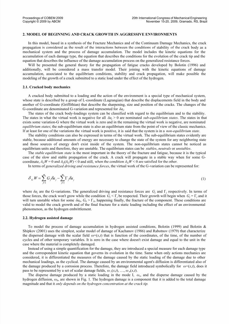
The evolution of the hydrogen damage and of the static damage at the crack tip, can be expressed for:
h
t
h
hh
c
c
cdt
d exp (2)
s
s
th
c
s
t dt
d 1 (3)
where s and h are the magnitudes of s and h at the crack tip; h is the measure of the damage at the crack tip
corresponding to the saturation state; ct is the evolution of the concentration in the time and ch is the stationary
concentration of the hydrogen, reached for a stationary crack. is the average value of the tensile stress that acts in a
considered material point. s characterizes the resistance to the damage produced by the static loading and th it is aresistance threshold parameter. The m s exponent is similar to the exponents of the equations of fatigue and crack growth
rate curves that, under certain conditions, have closed values; t c is a time constant whose magnitude can depend on the
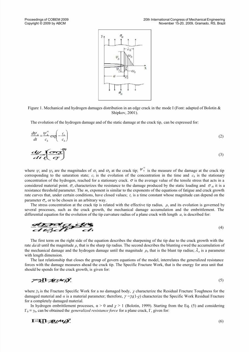
parameter s, or to be chosen in an arbitrary way.The stress concentration at the crack tip is related with the effective tip radius, ρ, and its evolution is governed by
several processes, such as the crack growth, the mechanical damage accumulation and the embrittlement. The
differential equation for the evolution of the tip curvature radius of a plane crack with length a, is described for:
d
d
dt
da
dt
d s
b
a
s
(4)
The first term on the right side of the equation describes the sharpening of the tip due to the crack growth with the
rate da/dt until the magnitude ρ s that is the sharp tip radius. The second describes the blunting owed the accumulation ofthe mechanical damage and the hydrogen damage until the magnitude ρb that is the blunt tip radius; a is a parameter
with length dimension.
The last relationship that closes the group of govern equations of the model, interrelates the generalized resistance
forces with the damage measures ahead the crack tip. The Specific Fracture Work, that is the energy for area unit thatshould be spends for the crack growth, is given for:
)(1[0 h s (5)
where 0 is the Fracture Specific Work for a no damaged body, χ characterize the Residual Fracture Toughness for the
damaged material and α is a material parameter; therefore, = 0(1- χ ) characterize the Specific Work Residual Fracturefor a completely damaged material.
In hydrogen embrittlement processes, α > 0 and χ ≥ 1 (Bolotin, 1999). Starting from the Eq. (5) and considering
Г0 ≡ γ0, can be obtained the generalized resistance force for a plane crack, Γ, given for:
)(1[0 h s (6)
8/12/2019 Artigo COBEM 2009 VFinal
http://slidepdf.com/reader/full/artigo-cobem-2009-vfinal 4/10
Proceedings of COBEM 2009 20th International Congress of Mechanical EngineeringCopyright © 2009 by ABCM November 15-20, 2009, Gramado, RS, Brazil
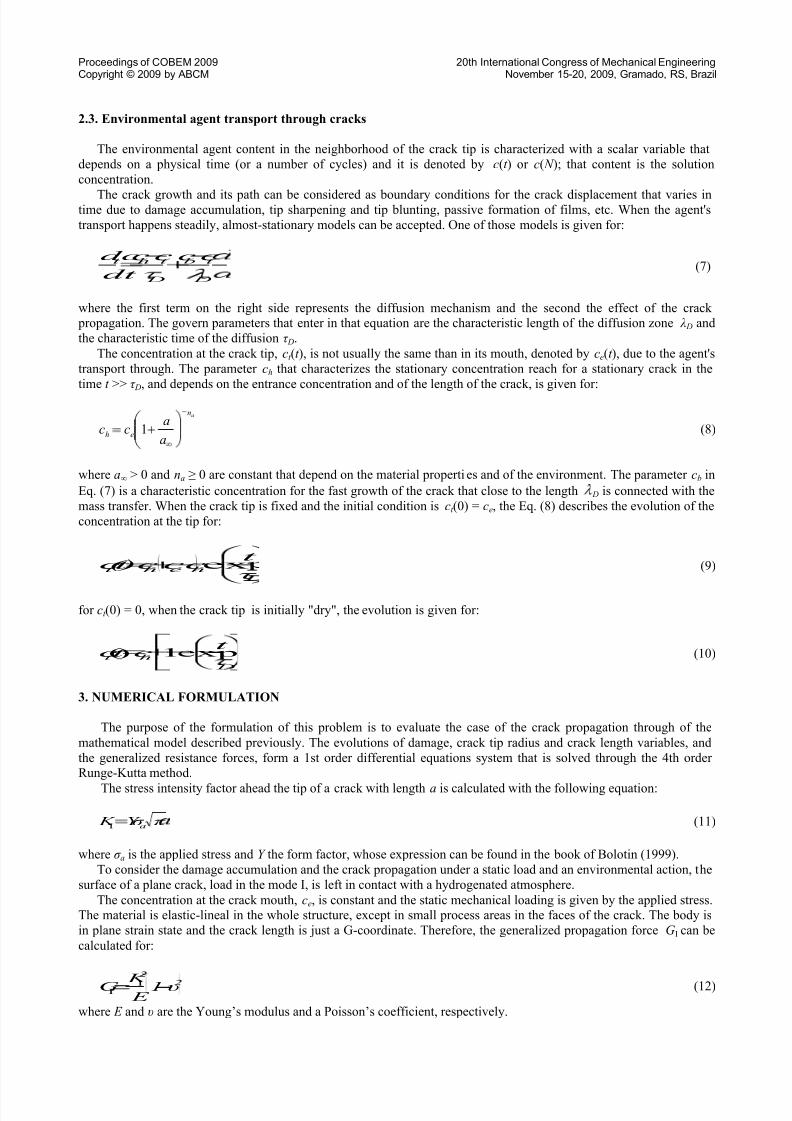
2.3. Environmental agent transport through cracks
The environmental agent content in the neighborhood of the crack tip is characterized with a scalar variable that
depends on a physical time (or a number of cycles) and it is denoted by c(t ) or c( N ); that content is the solution
concentration.
The crack growth and its path can be considered as boundary conditions for the crack displacement that varies intime due to damage accumulation, tip sharpening and tip blunting, passive formation of films, etc. When the agent's
transport happens steadily, almost-stationary models can be accepted. One of those models is given for:
cccc
dt
dc
D
t b
D
t ht
(7)
where the first term on the right side represents the diffusion mechanism and the second the effect of the crack propagation. The govern parameters that enter in that equation are the characteristic length of the diffusion zone λ D and
the characteristic time of the diffusion τ D.
The concentration at the crack tip, ct (t ), is not usually the same than in its mouth, denoted by ce(t ), due to the agent's
transport through. The parameter ch that characterizes the stationary concentration reach for a stationary crack in the
time t >> τ D, and depends on the entrance concentration and of the length of the crack, is given for:
an
eha
acc 1 (8)
where a∞ > 0 and na ≥ 0 are constant that depend on the material properties and of the environment. The parameter cb in
Eq. (7) is a characteristic concentration for the fast growth of the crack that close to the length D is connected with the
mass transfer. When the crack tip is fixed and the initial condition is ct (0) = ce, the Eq. (8) describes the evolution of the
concentration at the tip for:
heht τ
t ccc )t ( c ex (9)
for ct (0) = 0, when the crack tip is initially "dry", the evolution is given for:
D
ht
t ct c exp1)( (10)
3. NUMERICAL FORMULATION
The purpose of the formulation of this problem is to evaluate the case of the crack propagation through of the
mathematical model described previously. The evolutions of damage, crack tip radius and crack length variables, and
the generalized resistance forces, form a 1st order differential equations system that is solved through the 4th orderRunge-Kutta method.
The stress intensity factor ahead the tip of a crack with length a is calculated with the following equation:
π σ Y K aI (11)
where σ a is the applied stress and Y the form factor, whose expression can be found in the book of Bolotin (1999).
To consider the damage accumulation and the crack propagation under a static load and an environmental action, the
surface of a plane crack, load in the mode I, is left in contact with a hydrogenated atmosphere.
The concentration at the crack mouth, ce, is constant and the static mechanical loading is given by the applied stress.The material is elastic-lineal in the whole structure, except in small process areas in the faces of the crack. The body is
in plane strain state and the crack length is just a G-coordinate. Therefore, the generalized propagation force GI can be
calculated for:
2
2
υ1 E K G I
I (12)
where E and υ are the Young’s modulus and a Poisson’s coefficient, respectively.
8/12/2019 Artigo COBEM 2009 VFinal
http://slidepdf.com/reader/full/artigo-cobem-2009-vfinal 5/10
Proceedings of COBEM 2009 20th International Congress of Mechanical EngineeringCopyright © 2009 by ABCM November 15-20, 2009, Gramado, RS, Brazil
In an almost-stationary approach is be considered the rate of crack growth, da/dt , inside of a small interval of time
enough so that the other variables vary very slowly, in other words, treating them as constant in that interval. Therefore,
using the Eqs. (2) and (3) and the equilibrium condition give in the Eq. (6), with χ =1 and Γ= G, one has:
α1
0
h
t
h
h
h
m
s
tht
c
s
Γ
G 1
c
c
c
ψ λ
σ
σ σ
t
λ
dt
da
s
exp
(13)
To evaluate the mechanical damage, the tension-deformation and concentration fields in the body during the
considered process should be known, being able to be used some simple approaches based on an analogy among the
stress concentration factor, K t , and the stress intensity factor, K I. This analogy provides an approximate formula for the
stress concentration factor at the tip and for the distribution of the normal stress in its front that can be calculated for:
2/ 1
21 aY K
t (14)
1
at
ρ
a x41σ K σ (15)
The Eq. (14) is an extension of the well-know Neuber's formula that calculates the stress concentration factor taking
into account the form factor Y . The Eq. (15) is the simplest of the Shin's empiric equations, where ( x-a) = ξ = 10 ρ. This
approach provides good results in plane problems, because that distance is usually enough to esteem the damage field,
especially when the distant components of the field can be despised.
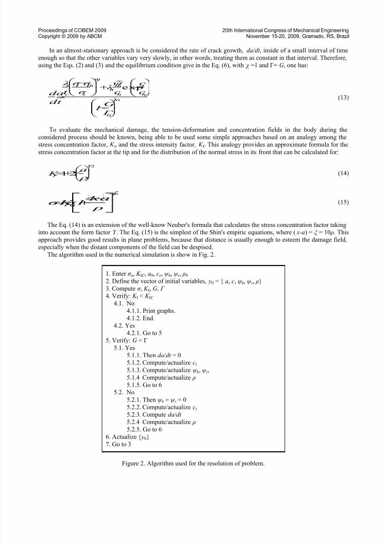
The algorithm used in the numerical simulation is show in Fig. 2.
1. Enter σ a, K IC , a0, ce, ψ h, ψ s, ρ0
2. Define the vector of initial variables, y0 = { a, c, ψ h, ψ s, ρ}
3. Compute σ , K I, G, Г 4. Verify: K I < K IC
4.1. No
4.1.1. Print graphs.
4.1.2. End.
4.2. Yes4.2.1. Go to 5
5. Verify: G < Г
5.1. Yes
5.1.1. Then da/dt = 05.1.2. Compute/actualize ct
5.1.3. Compute/actualize ψ h, ψ s,
5.1.4 Compute/actualize ρ
5.1.5. Go to 65.2. No
5.2.1. Then ψ h = ψ s = 0
5.2.2. Compute/actualize ct
5.2.3. Compute da/dt
5.2.4 Compute/actualize ρ
5.2.5. Go to 6
6. Actualize { y0}
7. Go to 3
Figure 2. Algorithm used for the resolution of problem.
8/12/2019 Artigo COBEM 2009 VFinal
http://slidepdf.com/reader/full/artigo-cobem-2009-vfinal 6/10
Proceedings of COBEM 2009 20th International Congress of Mechanical EngineeringCopyright © 2009 by ABCM November 15-20, 2009, Gramado, RS, Brazil
4. RESULTS AND DISCUSSION
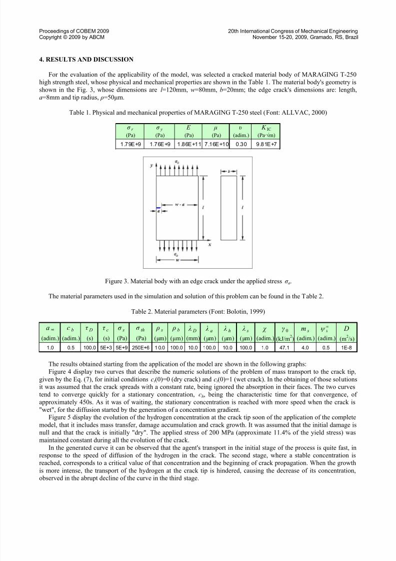
For the evaluation of the applicability of the model, was selected a cracked material body of MARAGING T-250
high strength steel, whose physical and mechanical properties are shown in the Table 1. The material body's geometry is
shown in the Fig. 3, whose dimensions are l =120mm, w=80mm, b=20mm; the edge crack's dimensions are: length,
a=8mm and tip radius, ρ=50μm.
Table 1. Physical and mechanical properties of MARAGING T-250 steel (Font: ALLVAC, 2000)
σ r σ y E μ υ K IC
(Pa) (Pa) (Pa) (Pa) (adim.) (Pa∙√m)
1 .7 9E +9 1 .7 6E +9 1 .8 6E +1 1 7 .1 6E +1 0 0 .3 0 9 .8 1E +7
Figure 3. Material body with an edge crack under the applied stress σ a.
The material parameters used in the simulation and solution of this problem can be found in the Table 2.
Table 2. Material parameters (Font: Bolotin, 1999)
a ∞ c b τ D τ c σ s σ th ρ s ρ b λ D λ a λ h λ s χ γ 0 m s D
(adim.) (adim.) (s) (s) (Pa) (Pa) (μm) (μm) (mm) (μm) (μm) (μm) (adim.) (kJ/m2) (adim.) (adim.) (m
2/s)
1.0 0.5 100.0 5E+3 5E+9 250E+6 1 0.0 100.0 10.0 100.0 10.0 100.0 1.0 47.1 4.0 0.5 1E-8
h
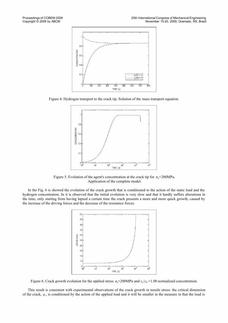
The results obtained starting from the application of the model are shown in the following graphs:
Figure 4 display two curves that describe the numeric solutions of the problem of mass transport to the crack tip,
given by the Eq. (7), for initial conditions ct (0)=0 (dry crack) and ct (0)=1 (wet crack). In the obtaining of those solutionsit was assumed that the crack spreads with a constant rate, being ignored the absorption in their faces. The two curves
tend to converge quickly for a stationary concentration, ch, being the characteristic time for that convergence, ofapproximately 450s. As it was of waiting, the stationary concentration is reached with more speed when the crack is
"wet", for the diffusion started by the generation of a concentration gradient.Figure 5 display the evolution of the hydrogen concentration at the crack tip soon of the application of the complete
model, that it includes mass transfer, damage accumulation and crack growth. It was assumed that the initial damage is
null and that the crack is initially "dry". The applied stress of 200 MPa (approximate 11.4% of the yield stress) was
maintained constant during all the evolution of the crack.
In the generated curve it can be observed that the agent's transport in the initial stage of the process is quite fast, in
response to the speed of diffusion of the hydrogen in the crack. The second stage, where a stable concentration is
reached, corresponds to a critical value of that concentration and the beginning of crack propagation. When the growth
is more intense, the transport of the hydrogen at the crack tip is hindered, causing the decrease of its concentration,observed in the abrupt decline of the curve in the third stage.
8/12/2019 Artigo COBEM 2009 VFinal
http://slidepdf.com/reader/full/artigo-cobem-2009-vfinal 7/10
Proceedings of COBEM 2009 20th International Congress of Mechanical EngineeringCopyright © 2009 by ABCM November 15-20, 2009, Gramado, RS, Brazil
Figure 4. Hydrogen transport to the crack tip. Solution of the mass transport equation.
Figure 5. Evolution of the agent's concentration at the crack tip for σ a=200MPa.
Application of the complete model.
In the Fig. 6 is showed the evolution of the crack growth that is conditioned to the action of the static load and the
hydrogen concentration. In it is observed that the initial evolution is very slow and that it hardly suffers alterations in
the time; only starting from having lapsed a certain time the crack presents a more and more quick growth, caused by
the increase of the driving forces and the decrease of the resistance forces.
Figure 6. Crack growth evolution for the applied stress σ a=200MPa and ce/ch =1.00 normalized concentration.
This result is consistent with experimental observations of the crack growth in tensile stress: the critical dimension
of the crack, ac, is conditioned by the action of the applied load and it will be smaller in the measure in that the load is
8/12/2019 Artigo COBEM 2009 VFinal
http://slidepdf.com/reader/full/artigo-cobem-2009-vfinal 8/10
Proceedings of COBEM 2009 20th International Congress of Mechanical EngineeringCopyright © 2009 by ABCM November 15-20, 2009, Gramado, RS, Brazil
bigger. For very high applied stresses, related to the yield limit of the material, the critical dimension will be reachedafter a growth of some few millimeters (e.g., approximately 3mm for an applied stress of 50% of the yield limit, under
the same conditions described in this simulation), for after to occur the instantaneous fracture of the component. In very
low levels of the applied load, it simply represents the fail of the structure caused for the crack growth until the limit of
the dimensions of the material body, due to the absence of the necessary ligament so that the critical dimension of crack
will be reached.Therefore, under certain load conditions, the highest point in the curves coincides with the critical dimension of the
crack, representing the instantaneous fracture of the component due to the generated instability when the resistance
forces to the propagation are overcome.
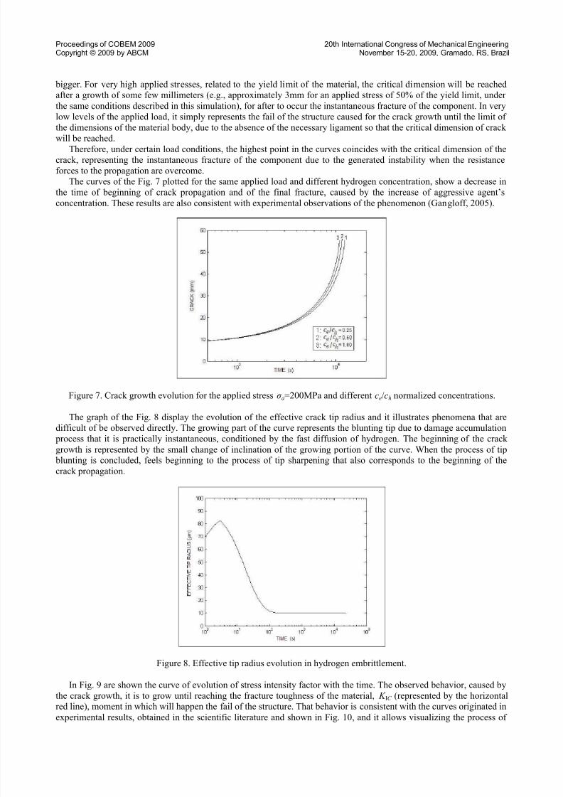
The curves of the Fig. 7 plotted for the same applied load and different hydrogen concentration, show a decrease in
the time of beginning of crack propagation and of the final fracture, caused by the increase of aggressive agent’s
concentration. These results are also consistent with experimental observations of the phenomenon (Gangloff, 2005).
Figure 7. Crack growth evolution for the applied stress σ a=200MPa and different ce/ch normalized concentrations.
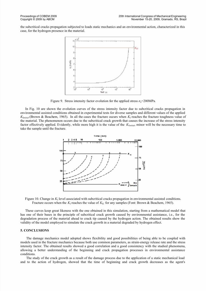
The graph of the Fig. 8 display the evolution of the effective crack tip radius and it illustrates phenomena that aredifficult of be observed directly. The growing part of the curve represents the blunting tip due to damage accumulation
process that it is practically instantaneous, conditioned by the fast diffusion of hydrogen. The beginning of the crack
growth is represented by the small change of inclination of the growing portion of the curve. When the process of tip blunting is concluded, feels beginning to the process of tip sharpening that also corresponds to the beginning of the
crack propagation.
Figure 8. Effective tip radius evolution in hydrogen embrittlement.
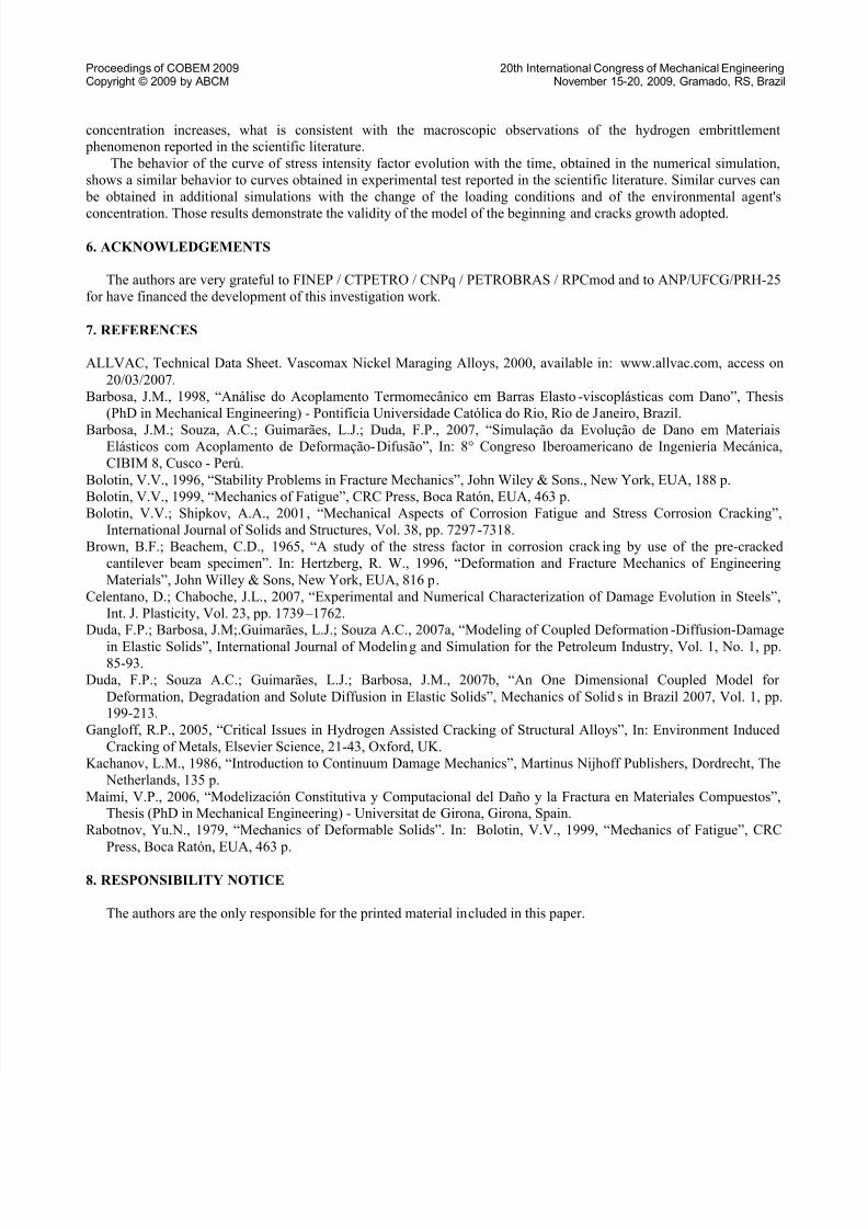
In Fig. 9 are shown the curve of evolution of stress intensity factor with the time. The observed behavior, caused by
the crack growth, it is to grow until reaching the fracture toughness of the material, K IC (represented by the horizontalred line), moment in which will happen the fail of the structure. That behavior is consistent with the curves originated in
experimental results, obtained in the scientific literature and shown in Fig. 10, and it allows visualizing the process of
8/12/2019 Artigo COBEM 2009 VFinal
http://slidepdf.com/reader/full/artigo-cobem-2009-vfinal 9/10
8/12/2019 Artigo COBEM 2009 VFinal
http://slidepdf.com/reader/full/artigo-cobem-2009-vfinal 10/10
Proceedings of COBEM 2009 20th International Congress of Mechanical EngineeringCopyright © 2009 by ABCM November 15-20, 2009, Gramado, RS, Brazil
concentration increases, what is consistent with the macroscopic observations of the hydrogen embrittlement phenomenon reported in the scientific literature.
The behavior of the curve of stress intensity factor evolution with the time, obtained in the numerical simulation,
shows a similar behavior to curves obtained in experimental test reported in the scientific literature. Similar curves can
be obtained in additional simulations with the change of the loading conditions and of the environmental agent's
concentration. Those results demonstrate the validity of the model of the beginning and cracks growth adopted.
6. ACKNOWLEDGEMENTS
The authors are very grateful to FINEP / CTPETRO / CNPq / PETROBRAS / RPCmod and to ANP/UFCG/PRH-25
for have financed the development of this investigation work.
7. REFERENCES
ALLVAC, Technical Data Sheet. Vascomax Nickel Maraging Alloys, 2000, available in: www.allvac.com, access on
20/03/2007.
Barbosa, J.M., 1998, “Análise do Acoplamento Termomecânico em Barras Elasto-viscoplásticas com Dano”, Thesis
(PhD in Mechanical Engineering) - Pontifícia Universidade Católica do Rio, Rio de Janeiro, Brazil.
Barbosa, J.M.; Souza, A.C.; Guimarães, L.J.; Duda, F.P., 2007, “Simulação da Evolução de Dano em MateriaisElásticos com Acoplamento de Deformação-Difusão”, In: 8° Congreso Iberoamericano de Ingeniería Mecánica,
CIBIM 8, Cusco - Perú.
Bolotin, V.V., 1996, “Stability Problems in Fracture Mechanics”, John Wiley & Sons., New York, EUA, 188 p.
Bolotin, V.V., 1999, “Mechanics of Fatigue”, CRC Press, Boca Ratón, EUA, 463 p.
Bolotin, V.V.; Shipkov, A.A., 2001, “Mechanical Aspects of Corrosion Fatigue and Stress Corrosion Cracking”,
International Journal of Solids and Structures, Vol. 38, pp. 7297-7318.
Brown, B.F.; Beachem, C.D., 1965, “A study of the stress factor in corrosion crack ing by use of the pre-cracked
cantilever beam specimen”. In: Hertzberg, R. W., 1996, “Deformation and Fracture Mechanics of Engineering
Materials”, John Willey & Sons, New York, EUA, 816 p.
Celentano, D.; Chaboche, J.L., 2007, “Experimental and Numerical Characterization of Damage Evolution in Steels”,
Int. J. Plasticity, Vol. 23, pp. 1739 – 1762.Duda, F.P.; Barbosa, J.M;.Guimarães, L.J.; Souza A.C., 2007a, “Modeling of Coupled Deformation-Diffusion-Damage
in Elastic Solids”, International Journal of Modeling and Simulation for the Petroleum Industry, Vol. 1, No. 1, pp.85-93.
Duda, F.P.; Souza A.C.; Guimarães, L.J.; Barbosa, J.M., 2007b, “An One Dimensional Coupled Model for
Deformation, Degradation and Solute Diffusion in Elastic Solids”, Mechanics of Solids in Brazil 2007, Vol. 1, pp.199-213.
Gangloff, R.P., 2005, “Critical Issues in Hydrogen Assisted Cracking of Structural Alloys”, In: Environment Induced
Cracking of Metals, Elsevier Science, 21-43, Oxford, UK.
Kachanov, L.M., 1986, “Introduction to Continuum Damage Mechanics”, Martinus Nijhoff Publishers, Dordrecht, The
Netherlands, 135 p.
Maimí, V.P., 2006, “Modelización Constitutiva y Computacional del Daño y la Fractura en Materiales Compuestos”,Thesis (PhD in Mechanical Engineering) - Universitat de Girona, Girona, Spain.
Rabotnov, Yu.N., 1979, “Mechanics of Deformable Solids”. In: Bolotin, V.V., 1999, “Mechanics of Fatigue”, CRC
Press, Boca Ratón, EUA, 463 p.
8. RESPONSIBILITY NOTICE
The authors are the only responsible for the printed material included in this paper.