Valvulas Safi Valvulas de Diafragma PVC U PPH PVDF DN15 A ...
14
SERIE 2100-2200-2300-2107-2108- 2109-2207-2208-2209-2307-2308-2309 TDS-DIAPH-2300-00-EN 01/02/2018 DIAPHRAGM VALVE - DN15 (1/2") to DN50 (2") – PVC-U, PP-H, PVDF PVC-U PP-H PVDF SAFI Av. Jacques Moison – BP 1 26770 TAULIGNAN FRANCE Tél.: (+33) 4 75 53 56 29 Fax : (+33) 4 75 53 62 78 [email protected] SAFI Deutschland Kunststoffarmaturen Vertriebs GmbH Jahnstrasse 29 64319 PFUNGSTADT DEUTSCHLAND Tél. : (+49) 61 57 81 919 Fax : (+49) 61 57 82 025 [email protected] SAFI Fabrica de Valvulas C/ Carboners, 35 Pol. Ind. La Cometa 43700 EL VENDRELL TARRAGONA-ESPAÑA Tel.: (+34) 977 665 147 Fax : (+34) 977 664 989 [email protected] SAFI America Las Garzas Trade Center Las Garzas #950, B Quilicura SANTIAGO – CHILE Tél.: (+56 2) 2 510 3500 Fax : (+56 2) 2 510 3507 [email protected] SAFI Limited 35 Holton Road Holton Heath Trading Park POOLE Dorset - BH16 6LT UNITED KINGDOM Tél.: (+44) 1202 624618 Fax : (+44) 1202 628500 [email protected] Les descriptions et caractéristiques figurant sur ce document sont données uniquement à titre d’information et non d’engagement contractuel. SAFI se réserve le droit d’effectuer sans préavis, toute modification. SAFI has a policy of continuously developing its product range and the above data is subject to change without prior notification. www.safi-valves.com 1 Die Beschreibungen und Daten, die sich auf diesem Dokument befinden, sind rein informativ und unverbindlich. SAFI behält sich vor, ohne Vorankündigung Änderungen vorzunehmen, die als technisch notwendig erachtet werden. Las descripciones y características que figuran en este documento son indicativas. En ningún caso son contractuales. SAFI se reserva el derecho sin previo aviso de efectuar cualquier modificación. Conform to the 2014/68/EU Directive MAIN FEATURES Optimized pressure drop due to body design. Stainless steel mounting inserts designed to support the valve. Same distance between the inserts for all DN. Standard handwheel suitable for handle extension and/or locking system. EPDM, FPM, or PTFE diaphragm (EPDM backing). Color wheel according to diaphragm material (Red= EPDM, Green = FPM, Blue = PTFE). The design of diaphragm valves does not allow operation under vacuum. STANDARDS AND APPROVALS DN40 – PP-H Metric spigot outlets DN40 – PP-H Double union DN40 – PP-H Flanged NR320 : Certification scheme of materials and equipment for the classification of marine units
Transcript of Valvulas Safi Valvulas de Diafragma PVC U PPH PVDF DN15 A ...

SER
IE 2
100
-220
0-2
300
-21
07
-21
08
-2
10
9-2
20
7-2
208
-22
09-2
307
-230
8-2
30
9
FT- RTS-XXX-00
TDS-DIAPH-2300-00-EN 01/02/2018
DIAPHRAGM VALVE - DN15 (1/2") to DN50 (2") – PVC-U, PP-H, PVDF
PV
C-U
PP
-H
PV
DF
SAFI Av. Jacques Moison – BP 1 26770 TAULIGNAN FRANCE Tél.: (+33) 4 75 53 56 29 Fax : (+33) 4 75 53 62 78 [email protected]
SAFI Deutschland Kunststoffarmaturen Vertriebs GmbH Jahnstrasse 29 64319 PFUNGSTADT DEUTSCHLAND Tél. : (+49) 61 57 81 919 Fax : (+49) 61 57 82 025 [email protected]
SAFI Fabrica de Valvulas C/ Carboners, 35 Pol. Ind. La Cometa 43700 EL VENDRELL TARRAGONA-ESPAÑA Tel.: (+34) 977 665 147 Fax : (+34) 977 664 989 [email protected]
SAFI America Las Garzas Trade Center Las Garzas #950, B Quilicura SANTIAGO – CHILE Tél.: (+56 2) 2 510 3500 Fax : (+56 2) 2 510 3507 [email protected]
SAFI Limited 35 Holton Road Holton Heath Trading Park POOLE Dorset - BH16 6LT UNITED KINGDOM Tél.: (+44) 1202 624618 Fax : (+44) 1202 628500 [email protected]
Les descriptions et caractéristiques figurant sur ce document sont données uniquement à titre d’information et non d’engagement contractuel. SAFI se réserve le droit d’effectuer sans préavis, toute modification. SAFI has a policy of continuously developing its product range and the above data is subject to change without prior notification.
www.safi-valves.com
1
Die Beschreibungen und Daten, die sich auf diesem Dokument befinden, sind rein informativ und unverbindlich. SAFI behält sich vor, ohne Vorankündigung Änderungen vorzunehmen, die als technisch notwendig erachtet werden. Las descripciones y características que figuran en este documento son indicativas. En ningún caso son contractuales. SAFI se reserva el derecho sin previo aviso de efectuar cualquier modificación.
Conform to the 2014/68/EU Directive
MAIN FEATURES
Optimized pressure drop due to body design.
Stainless steel mounting inserts designed to support the valve. Same distance between the inserts for all DN.
Standard handwheel suitable for handle extension and/or locking system.
EPDM, FPM, or PTFE diaphragm (EPDM backing).
Color wheel according to diaphragm material (Red= EPDM, Green = FPM, Blue = PTFE).
The design of diaphragm valves does not allow operation under vacuum.
STANDARDS AND APPROVALS
DN40 – PP-H
Metric spigot outlets
DN40 – PP-H
Double union
DN40 – PP-H
Flanged
NR320 : Certification scheme of materials and equipment for the classification of marine units

SER
IE 2
100
-220
0-2
300
-21
07
-21
08
-2
10
9-2
20
7-2
208
-22
09-2
307
-230
8-2
30
9
Les descriptions et caractéristiques figurant sur ce document sont données uniquement à titre d’information et non d’engagement contractuel. SAFI se réserve le droit d’effectuer sans préavis, toute modification. SAFI has a policy of continuously developing its product range and the above data is subject to change without prior notification.
www.safi-valves.com
2
Die Beschreibungen und Daten, die sich auf diesem Dokument befinden, sind rein informativ und unverbindlich. SAFI behält sich vor, ohne Vorankündigung Änderungen vorzunehmen, die als technisch notwendig erachtet werden. Las descripciones y características que figuran en este documento son indicativas. En ningún caso son contractuales. SAFI se reserva el derecho sin previo aviso de efectuar cualquier modificación.
TDS-DIAPH-2300-00-EN 01/02/2018 P
VC
-U
PP
-H
PV
DF
DIMENSIONS
Metric spigots version
Diagram representing a DN50
WEIGHT (in Kg)
DN Ød G H J ØK L M N P Q R PVC-U PP-H PVDF
15 20 21,5 120 13 101 124 10 17 91 75 M6 0,76 0,68 0,80
20 25 21,5 120 13 101 144 10 19,5 91 75 M6 0,79 0,70 0,83
25 32 21,5 120 13 101 154 10 23,5 91 75 M6 0,80 0,71 0,85
32 40 32 142 25 139 174 8 27 110 101 M8 1,50 1,32 1,61
40 50 32 142 25 139 194 8 32 110 101 M8 1,56 1,34 1,66
50 63 39 175 30 163 224 8 39 137 123 M8 2,80 2,4 3,02
Ø d
L
N
R
G
SER
IE 2
100
-220
0-2
300
-21
07
-21
08
-2
10
9-2
20
7-2
208
-22
09-2
307
-230
8-2
30
9
Les descriptions et caractéristiques figurant sur ce document sont données uniquement à titre d’information et non d’engagement contractuel. SAFI se réserve le droit d’effectuer sans préavis, toute modification. SAFI has a policy of continuously developing its product range and the above data is subject to change without prior notification.
www.safi-valves.com
3
Die Beschreibungen und Daten, die sich auf diesem Dokument befinden, sind rein informativ und unverbindlich. SAFI behält sich vor, ohne Vorankündigung Änderungen vorzunehmen, die als technisch notwendig erachtet werden. Las descripciones y características que figuran en este documento son indicativas. En ningún caso son contractuales. SAFI se reserva el derecho sin previo aviso de efectuar cualquier modificación.
TDS-DIAPH-2300-00-EN 01/02/2018 P
VC
-U
PP
-H
PV
DF
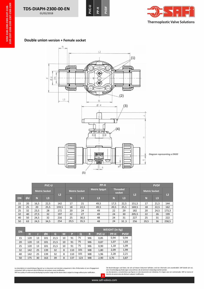
Double union version + Female socket
PVC-U PP-H PVDF
Metric Socket
L2
Metric Socket Metric Spigot
Threaded
socket L2
Metric Socket
L2 DN Ød N L3 N L3 L3 N L3 N L3
15 20 16,5 22,5 142 17 21 49,5 17,5 22,5 151,5 17 21,5 144
20 25 20 25,5 159,5 18 22,5 49,5 20,5 25,5 169,5 18 22,5 162
25 32 23,5 28 172 20 24 49 22 29 182 20 24,5 173,3
32 40 27,5 32 197 22 27 49 24 30 205,5 22 26 199
40 50 24,5 32 216 25 30,5 48 24 31 227 25 31 222
50 63 24,5 34,5 254 29,5 35,5 48 24 32 ,5 256 29,5 36 258,5
DN WEIGHT (in Kg)
H J ØK G M P Q R PVC-U PP-H PVDF
15 120 13 101 21,5 10 91 75 M6 0,85 0,94 0,94
20 120 13 101 21,5 10 91 75 M6 0,87 1,07 1,03
25 120 13 101 21,5 10 91 75 M6 0,90 1,18 1,09
32 142 25 139 32 8 110 101 M8 1,80 2,09 1,99
40 142 25 139 32 8 110 101 M8 1,96 2,28 2,21
50 175 30 163 39 8 137 123 M8 2,90 3,70 3,87
Diagram representing a DN50
(2)
(3)
(4)
(5)
N
R
G
L2
(1)
L3
Ø d

SER
IE 2
100
-220
0-2
300
-21
07
-21
08
-2
10
9-2
20
7-2
208
-22
09-2
307
-230
8-2
30
9
Les descriptions et caractéristiques figurant sur ce document sont données uniquement à titre d’information et non d’engagement contractuel. SAFI se réserve le droit d’effectuer sans préavis, toute modification. SAFI has a policy of continuously developing its product range and the above data is subject to change without prior notification.
www.safi-valves.com
4
Die Beschreibungen und Daten, die sich auf diesem Dokument befinden, sind rein informativ und unverbindlich. SAFI behält sich vor, ohne Vorankündigung Änderungen vorzunehmen, die als technisch notwendig erachtet werden. Las descripciones y características que figuran en este documento son indicativas. En ningún caso son contractuales. SAFI se reserva el derecho sin previo aviso de efectuar cualquier modificación.
TDS-DIAPH-2300-00-EN 01/02/2018 P
VC
-U
PP
-H
PV
DF
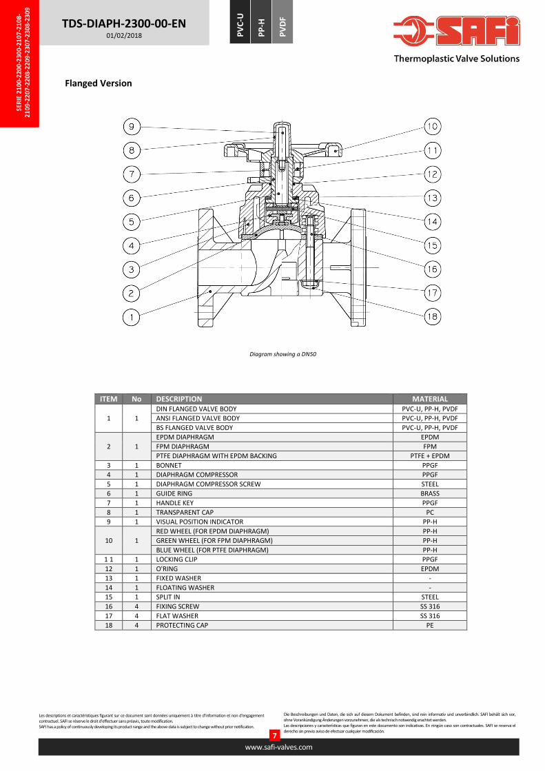
Flanged Version
NOTE: Our flanged valve body, designed as one-piece body, requires imperatively the use of bolts with adapted lengths for the connection. Using flat washers is highly recommended. The optimum tightening for the bolts of the flanges is obtained at a torque of 10 to 20 N.m.
Schéma représentant un DN50
ØB ØC L1
DN ØA DIN ANSI BS DIN ANSI BS E F PVC-U PP-H PVDF H J ØK G M P Q R 15 95 65 60 - 14 16 - 14 65 131 131 130,5 120 13 101 21,5 10 91 75 M6 20 105 75 70 - 14 16 - 16 75 151 150 150 120 13 101 21,5 10 91 75 M6 25 115 85 79,5 82 14 16 14 16 80 162 161 160,5 120 13 101 21,5 10 91 75 M6 32 140 100 89 87,3 18 16 14 18 90 181 181 180 142 25 139 32 8 110 101 M8 40 150 110 98,4 98,4 18 16 14 18 100 201 201 200 142 25 139 32 8 110 101 M8 50 165 125 120,6 114,3 18 19 18 20 115 232 231 230 175 30 163 39 8 137 123 M8
DIN = Drilling in accordance with EN1092-1 PN10/PN16 ANSI = Drilling in accordance with ASME B16.5 CLASS 150
WEIGHT (in Kg)
DN PVC-U PP-H PVDF 15 1,02 0,84 1,02
20 1,14 0,92 1,27
25 1,22 0,98 1,32
32 2,2 1,76 2,5
40 2,3 1,85 2,7
50 3,9 3,09 4,4
L1
R
G

SER
IE 2
100
-220
0-2
300
-21
07
-21
08
-2
10
9-2
20
7-2
208
-22
09-2
307
-230
8-2
30
9
Les descriptions et caractéristiques figurant sur ce document sont données uniquement à titre d’information et non d’engagement contractuel. SAFI se réserve le droit d’effectuer sans préavis, toute modification. SAFI has a policy of continuously developing its product range and the above data is subject to change without prior notification.
www.safi-valves.com
5
Die Beschreibungen und Daten, die sich auf diesem Dokument befinden, sind rein informativ und unverbindlich. SAFI behält sich vor, ohne Vorankündigung Änderungen vorzunehmen, die als technisch notwendig erachtet werden. Las descripciones y características que figuran en este documento son indicativas. En ningún caso son contractuales. SAFI se reserva el derecho sin previo aviso de efectuar cualquier modificación.
TDS-DIAPH-2300-00-EN 01/02/2018 P
VC
-U
PP
-H
PV
DF
PARTS LIST
Spigots version
Diagram showing a DN50
ITEM No DESCRIPTION MATERIAL
1 1 VALVE BODY WITH DIN METRIC SPIGOTS PVC-U, PP-H, PVDF
VALVE BODY WITH BS SPIGOTS PVC-U, PP-H, PVDF
2 1
EPDM DIAPHRAGM EPDM
FPM DIAPHRAGM FPM
PTFE DIAPHRAGM WITH EPDM BACKING PTFE + EPDM
3 1 BONNET PPGF
4 1 DIAPHRAGM COMPRESSOR PPGF
5 1 DIAPHRAGM COMPRESSOR SCREW STEEL
6 1 GUIDE RING BRASS
7 1 HANDLE KEY PPGF
8 1 TRANSPARENT CAP PC
9 1 VISUAL POSITION INDICATOR PP-H
10 1
RED WHEEL (FOR EPDM DIAPHRAGM) PP-H
GREEN WHEEL (FOR FPM DIAPHRAGM) PP-H
BLUE WHEEL (FOR PTFE DIAPHRAGM) PP-H
1 1 1 LOCKING CLIP PPGF
12 1 O'RING EPDM
13 1 FIXED WASHER -
14 1 FLOATING WASHER -
15 1 SPLIT IN STEEL
16 4 FIXING SCREW SS 316
17 4 FLAT WASHER SS 316
18 4 PROTECTING CAP PE

SER
IE 2
100
-220
0-2
300
-21
07
-21
08
-2
10
9-2
20
7-2
208
-22
09-2
307
-230
8-2
30
9
Les descriptions et caractéristiques figurant sur ce document sont données uniquement à titre d’information et non d’engagement contractuel. SAFI se réserve le droit d’effectuer sans préavis, toute modification. SAFI has a policy of continuously developing its product range and the above data is subject to change without prior notification.
www.safi-valves.com
6
Die Beschreibungen und Daten, die sich auf diesem Dokument befinden, sind rein informativ und unverbindlich. SAFI behält sich vor, ohne Vorankündigung Änderungen vorzunehmen, die als technisch notwendig erachtet werden. Las descripciones y características que figuran en este documento son indicativas. En ningún caso son contractuales. SAFI se reserva el derecho sin previo aviso de efectuar cualquier modificación.
TDS-DIAPH-2300-00-EN 01/02/2018 P
VC
-U
PP
-H
PV
DF
Double union version + Socket
Diagram showing a DN50
ITEM No DESCRIPTION MATERIAL 1 1 VALVE BODY WITH DIN FUSION SPIGOTS PVC-U, PP-H, PVDF
2 1
EPDM DIAPHRAGM EPDM
FPM DIAPHRAGM FPM
PTFE DIAPHRAGM WITH EPDM BACKING PTFE + EPDM
3 1 BONNET PPGF
4 1 DIAPHRAGM COMPRESSOR PPGF
5 1 DIAPHRAGM COMPRESSOR SCREW STEEL
6 1 GUIDE RING BRASS
7 1 HANDLE KEY PPGF
8 1 TRANSPARENT CAP PC
9 1 VISUAL POSITION INDICATOR PP-H
10 1
RED WHEEL (FOR EPDM DIAPHRAGM) PP-H
GREEN WHEEL (FOR FPM DIAPHRAGM) PP-H
BLUE WHEEL (FOR PTFE DIAPHRAGM) PP-H
1 1 1 LOCKING CLIP PPGF
12 1 O'RING EPDM
13 1 FIXED WASHER -
14 1 FLOATING WASHER -
15 1 SPLIT IN STEEL
16 4 FIXING SCREW SS 316
17 4 FLAT WASHER SS 316
18 4 PROTECTING CAP PE
19 2
PVC SOLVENT FEMALE UNION SOCKET PVC-U
PP-H FUSION FEMALE UNION SOCKET PP-H
PP-H FUSION UNION SPIGOT PP-H
PP-H THREADED UNION SOCKET PP-H
PVDF FUSION FEMALE UNION SOCKET PVDF
As standard, PTFE Diaphragm Valves are supplied with EPDM O-rings. On request, they can be delivered in FPM.
SER
IE 2
100
-220
0-2
300
-21
07
-21
08
-2
10
9-2
20
7-2
208
-22
09-2
307
-230
8-2
30
9
Les descriptions et caractéristiques figurant sur ce document sont données uniquement à titre d’information et non d’engagement contractuel. SAFI se réserve le droit d’effectuer sans préavis, toute modification. SAFI has a policy of continuously developing its product range and the above data is subject to change without prior notification.
www.safi-valves.com
7
Die Beschreibungen und Daten, die sich auf diesem Dokument befinden, sind rein informativ und unverbindlich. SAFI behält sich vor, ohne Vorankündigung Änderungen vorzunehmen, die als technisch notwendig erachtet werden. Las descripciones y características que figuran en este documento son indicativas. En ningún caso son contractuales. SAFI se reserva el derecho sin previo aviso de efectuar cualquier modificación.
TDS-DIAPH-2300-00-EN 01/02/2018 P
VC
-U
PP
-H
PV
DF
Flanged Version
Diagram showing a DN50
ITEM No DESCRIPTION MATERIAL
1 1
DIN FLANGED VALVE BODY PVC-U, PP-H, PVDF
ANSI FLANGED VALVE BODY PVC-U, PP-H, PVDF
BS FLANGED VALVE BODY PVC-U, PP-H, PVDF
2 1
EPDM DIAPHRAGM EPDM
FPM DIAPHRAGM FPM
PTFE DIAPHRAGM WITH EPDM BACKING PTFE + EPDM
3 1 BONNET PPGF
4 1 DIAPHRAGM COMPRESSOR PPGF
5 1 DIAPHRAGM COMPRESSOR SCREW STEEL
6 1 GUIDE RING BRASS
7 1 HANDLE KEY PPGF
8 1 TRANSPARENT CAP PC
9 1 VISUAL POSITION INDICATOR PP-H
10 1
RED WHEEL (FOR EPDM DIAPHRAGM) PP-H
GREEN WHEEL (FOR FPM DIAPHRAGM) PP-H
BLUE WHEEL (FOR PTFE DIAPHRAGM) PP-H
1 1 1 LOCKING CLIP PPGF
12 1 O'RING EPDM
13 1 FIXED WASHER -
14 1 FLOATING WASHER -
15 1 SPLIT IN STEEL
16 4 FIXING SCREW SS 316
17 4 FLAT WASHER SS 316
18 4 PROTECTING CAP PE
SER
IE 2
100
-220
0-2
300
-21
07
-21
08
-2
10
9-2
20
7-2
208
-22
09-2
307
-230
8-2
30
9
Les descriptions et caractéristiques figurant sur ce document sont données uniquement à titre d’information et non d’engagement contractuel. SAFI se réserve le droit d’effectuer sans préavis, toute modification. SAFI has a policy of continuously developing its product range and the above data is subject to change without prior notification.
www.safi-valves.com
8
Die Beschreibungen und Daten, die sich auf diesem Dokument befinden, sind rein informativ und unverbindlich. SAFI behält sich vor, ohne Vorankündigung Änderungen vorzunehmen, die als technisch notwendig erachtet werden. Las descripciones y características que figuran en este documento son indicativas. En ningún caso son contractuales. SAFI se reserva el derecho sin previo aviso de efectuar cualquier modificación.
TDS-DIAPH-2300-00-EN 01/02/2018 P
VC
-U
PP
-H
PV
DF
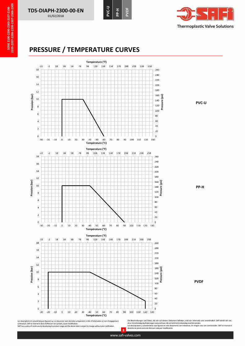
PRESSURE / TEMPERATURE CURVES
PVC-U
Temperature (°F)
Pre
ssio
n (
bar
)
Température (°C)
Pre
ssu
re (
psi
)
PP-H
Temperature (°F)
Pre
ssio
n (
bar
)
Température (°C)
Pre
ssu
re (
psi
)
PVDF
Temperature (°F)
Pre
ssio
n (
bar
)
Température (°C)
Pre
ssu
re (
psi
)

SER
IE 2
100
-220
0-2
300
-21
07
-21
08
-2
10
9-2
20
7-2
208
-22
09-2
307
-230
8-2
30
9
Les descriptions et caractéristiques figurant sur ce document sont données uniquement à titre d’information et non d’engagement contractuel. SAFI se réserve le droit d’effectuer sans préavis, toute modification. SAFI has a policy of continuously developing its product range and the above data is subject to change without prior notification.
www.safi-valves.com
9
Die Beschreibungen und Daten, die sich auf diesem Dokument befinden, sind rein informativ und unverbindlich. SAFI behält sich vor, ohne Vorankündigung Änderungen vorzunehmen, die als technisch notwendig erachtet werden. Las descripciones y características que figuran en este documento son indicativas. En ningún caso son contractuales. SAFI se reserva el derecho sin previo aviso de efectuar cualquier modificación.
TDS-DIAPH-2300-00-EN 01/02/2018 P
VC
-U
PP
-H
PV
DF
Pressure/Temperature Summary
PRESSURE LOSS
CHEMICAL RESISTANCE
DN Kv (m3/h)
15 6,1
20 9,4
25 12,2
32 24,3
40 29,3
50 45,8
Kv in accordance with NF EN 1267
FPM seals are not recommended for use < -5°C. Contact us for more information.
Diaphragm Working Pressure Working Temperature
PVC-U PP-H PVDF
EPDM / FPM / PTFE 10 bars at 20°C 0°C to + 60°C 0°C to + 90°C -20°C to +120°C
FPM 10 bars at 20°C 0°C to + 60°C 0°C to + 90°C -20°C to +120°C
PTFE 10 bars at 20°C 0°C to + 60°C 0°C to + 90°C -20°C to +120°C
Opening Angle (°)
Opening (%)
Kv
(%)
The chemical resistance of the valve is subject to the type of fluid, the temperature, the pressure, as well as the materials and seals of the valve.
Please contact us to have a personalized analysis of the resistance of one of our products to a given fluid
You can also consult, for information only, the table given in ISO 10358. However, this table cannot be considered as a recommendation by SAFI
who could not be held liable for the use of this document.
Our valves are guaranteed for an average fluid velocity in the pipeline of ≤ 2 m/s. Please contact us with the working conditions for any higher
speed.
SER
IE 2
100
-220
0-2
300
-21
07
-21
08
-2
10
9-2
20
7-2
208
-22
09-2
307
-230
8-2
30
9
Les descriptions et caractéristiques figurant sur ce document sont données uniquement à titre d’information et non d’engagement contractuel. SAFI se réserve le droit d’effectuer sans préavis, toute modification. SAFI has a policy of continuously developing its product range and the above data is subject to change without prior notification.
www.safi-valves.com
10
Die Beschreibungen und Daten, die sich auf diesem Dokument befinden, sind rein informativ und unverbindlich. SAFI behält sich vor, ohne Vorankündigung Änderungen vorzunehmen, die als technisch notwendig erachtet werden. Las descripciones y características que figuran en este documento son indicativas. En ningún caso son contractuales. SAFI se reserva el derecho sin previo aviso de efectuar cualquier modificación.
TDS-DIAPH-2300-00-EN 01/02/2018 P
VC
-U
PP
-H
PV
DF
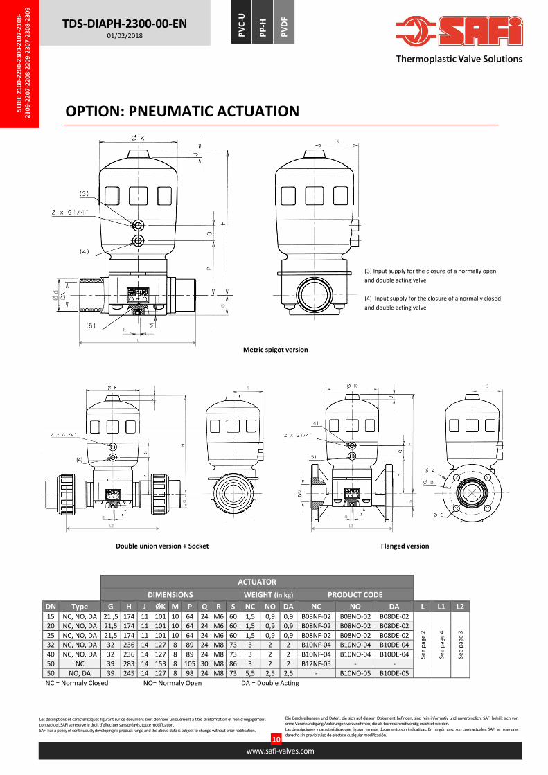
OPTION: PNEUMATIC ACTUATION
ACTUATOR
DIMENSIONS WEIGHT (in kg) PRODUCT CODE
DN Type G H J ØK M P Q R S NC NO DA NC NO DA L L1 L2 15 NC, NO, DA 21 ,5 174 11 101 10 64 24 M6 60 1,5 0,9 0,9 B08NF-02 B08NO-02 B08DE-02
See
pag
e 2
See
pag
e 4
See
pag
e 3
20 NC, NO, DA 21,5 174 11 101 10 64 24 M6 60 1,5 0,9 0,9 B08NF-02 B08NO-02 B08DE-02
25 NC, NO, DA 21,5 174 11 101 10 64 24 M6 60 1,5 0,9 0,9 B08NF-02 B08NO-02 B08DE-02
32 NC, NO, DA 32 236 14 127 8 89 24 M8 73 3 2 2 B10NF-04 B10NO-04 B10DE-04
40 NC, NO, DA 32 236 14 127 8 89 24 M8 73 3 2 2 B10NF-04 B10NO-04 B10DE-04
50 NC 39 283 14 153 8 105 30 M8 86 3 2 2 B12NF-05 - -
50 NO, DA 39 245 14 127 8 98 24 M8 73 5,5 2,5 2,5 - B10NO-05 B10DE-05
NC = Normaly Closed NO= Normaly Open DA = Double Acting
Flanged version Double union version + Socket
Metric spigot version
(4)
G
L2
R
S
G
L1
R
S
Ø d
G
L
R
S
(3) Input supply for the closure of a normally open
and double acting valve
(4) Input supply for the closure of a normally closed
and double acting valve
SER
IE 2
100
-220
0-2
300
-21
07
-21
08
-2
10
9-2
20
7-2
208
-22
09-2
307
-230
8-2
30
9
Les descriptions et caractéristiques figurant sur ce document sont données uniquement à titre d’information et non d’engagement contractuel. SAFI se réserve le droit d’effectuer sans préavis, toute modification. SAFI has a policy of continuously developing its product range and the above data is subject to change without prior notification.
www.safi-valves.com
11
Die Beschreibungen und Daten, die sich auf diesem Dokument befinden, sind rein informativ und unverbindlich. SAFI behält sich vor, ohne Vorankündigung Änderungen vorzunehmen, die als technisch notwendig erachtet werden. Las descripciones y características que figuran en este documento son indicativas. En ningún caso son contractuales. SAFI se reserva el derecho sin previo aviso de efectuar cualquier modificación.
TDS-DIAPH-2300-00-EN 01/02/2018 P
VC
-U
PP
-H
PV
DF
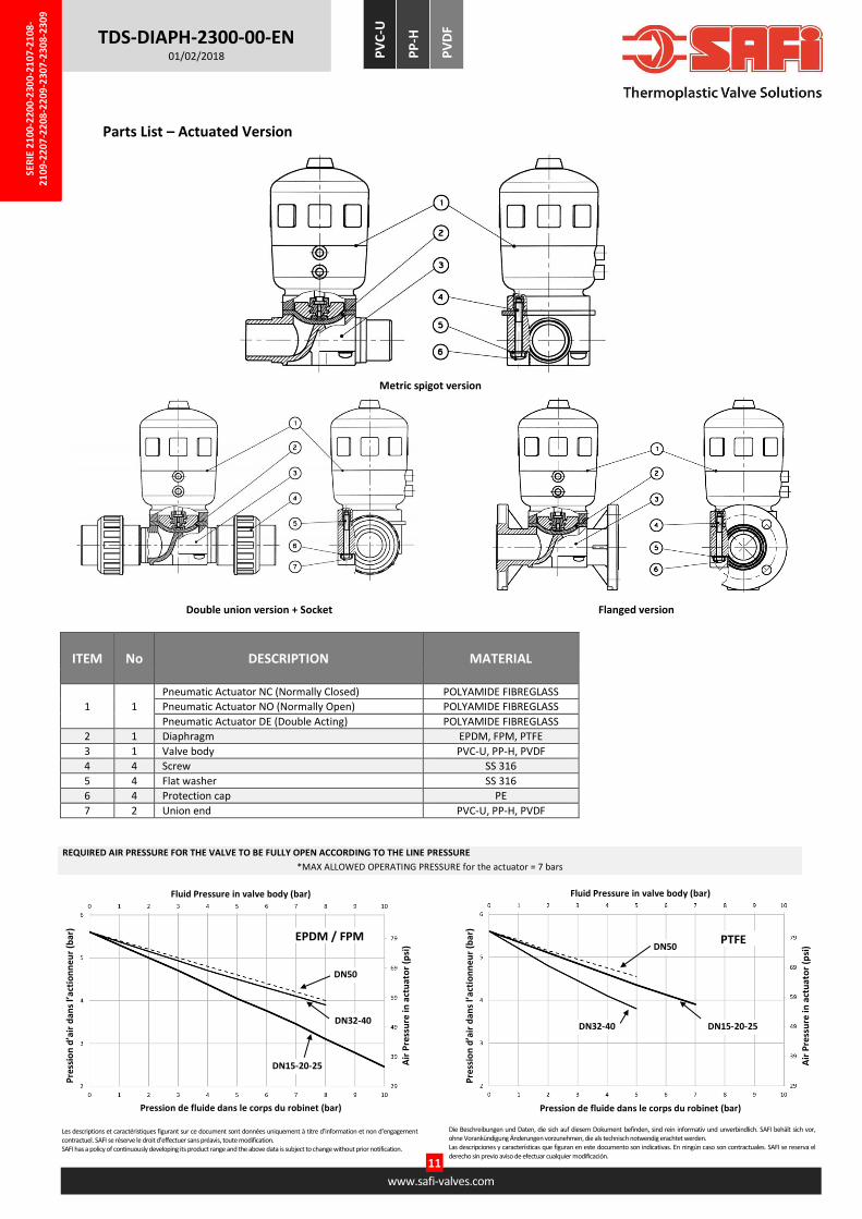
Parts List – Actuated Version
DN50
Pre
ssio
n d
’air
dan
s l’
acti
on
ne
ur
(bar
)
Pression de fluide dans le corps du robinet (bar)
Air
Pre
ssu
re in
act
uat
or
(psi
)
DN32-40
DN15-20-25
Fluid Pressure in valve body (bar)
EPDM / FPM
Flanged version Double union version + Socket
Metric spigot version
ITEM No DESCRIPTION MATERIAL
1 1
Pneumatic Actuator NC (Normally Closed) POLYAMIDE FIBREGLASS
Pneumatic Actuator NO (Normally Open) POLYAMIDE FIBREGLASS
Pneumatic Actuator DE (Double Acting) POLYAMIDE FIBREGLASS
2 1 Diaphragm EPDM, FPM, PTFE
3 1 Valve body PVC-U, PP-H, PVDF
4 4 Screw SS 316
5 4 Flat washer SS 316
6 4 Protection cap PE
7 2 Union end PVC-U, PP-H, PVDF
DN50
Pre
ssio
n d
’air
dan
s l’
acti
on
ne
ur
(bar
)
Pression de fluide dans le corps du robinet (bar)
Air
Pre
ssu
re in
act
uat
or
(psi
)
DN15-20-25 DN32-40
Fluid Pressure in valve body (bar)
PTFE
REQUIRED AIR PRESSURE FOR THE VALVE TO BE FULLY OPEN ACCORDING TO THE LINE PRESSURE
*MAX ALLOWED OPERATING PRESSURE for the actuator = 7 bars
SER
IE 2
100
-220
0-2
300
-21
07
-21
08
-2
10
9-2
20
7-2
208
-22
09-2
307
-230
8-2
30
9
Les descriptions et caractéristiques figurant sur ce document sont données uniquement à titre d’information et non d’engagement contractuel. SAFI se réserve le droit d’effectuer sans préavis, toute modification. SAFI has a policy of continuously developing its product range and the above data is subject to change without prior notification.
www.safi-valves.com
12
Die Beschreibungen und Daten, die sich auf diesem Dokument befinden, sind rein informativ und unverbindlich. SAFI behält sich vor, ohne Vorankündigung Änderungen vorzunehmen, die als technisch notwendig erachtet werden. Las descripciones y características que figuran en este documento son indicativas. En ningún caso son contractuales. SAFI se reserva el derecho sin previo aviso de efectuar cualquier modificación.
TDS-DIAPH-2300-00-EN 01/02/2018 P
VC
-U
PP
-H
PV
DF
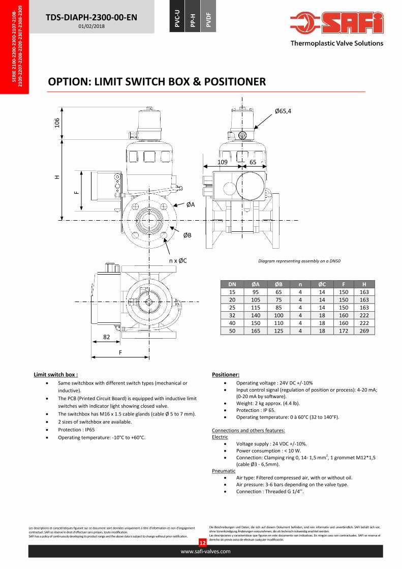
OPTION: LIMIT SWITCH BOX & POSITIONER
Diagram representing assembly on a DN50
DN ØA ØB n ØC F H
15 95 65 4 14 150 163
20 105 75 4 14 150 163
25 115 85 4 14 150 163
32 140 100 4 18 160 222
40 150 110 4 18 160 222
50 165 125 4 18 172 269
H
F
82
F
n x ØC
ØB
65
10
6
Ø65,4
109
ØA
Limit switch box :
Same switchbox with different switch types (mechanical or
inductive).
The PCB (Printed Circuit Board) is equipped with inductive limit
switches with indicator light showing closed valve.
The switchbox has M16 x 1.5 cable glands (cable Ø 5 to 7 mm).
2 sizes of switchbox are available.
Protection : IP65
Operating temperature: -10°C to +60°C.
Positioner:
Operating voltage : 24V DC +/-10%
Input control signal (regulation of position or process): 4-20 mA; (0-20 mA by software).
Weight: 2 kg approx. (4.4 lb).
Protection : IP 65.
Operating temperature: 0 à 60°C (32 to 140°F).
Connections and others features: Electric
Voltage supply : 24 VDC +/-10%.
Power consumption : < 10 W.
Connection: Clamping ring 0, 14- 1,5 mm2, 1 grommet M12*1,5 (cable Ø3 - 6,5mm).
Pneumatic
Air type: Filtered compressed air, with or without oil.
Air pressure: 3-6 bars depending on the valve type.
Connection : Threaded G 1/4’’.

SER
IE 2
100
-220
0-2
300
-21
07
-21
08
-2
10
9-2
20
7-2
208
-22
09-2
307
-230
8-2
30
9
Les descriptions et caractéristiques figurant sur ce document sont données uniquement à titre d’information et non d’engagement contractuel. SAFI se réserve le droit d’effectuer sans préavis, toute modification. SAFI has a policy of continuously developing its product range and the above data is subject to change without prior notification.
www.safi-valves.com
13
Die Beschreibungen und Daten, die sich auf diesem Dokument befinden, sind rein informativ und unverbindlich. SAFI behält sich vor, ohne Vorankündigung Änderungen vorzunehmen, die als technisch notwendig erachtet werden. Las descripciones y características que figuran en este documento son indicativas. En ningún caso son contractuales. SAFI se reserva el derecho sin previo aviso de efectuar cualquier modificación.
TDS-DIAPH-2300-00-EN 01/02/2018 P
VC
-U
PP
-H
PV
DF
OPTION: LOCKING SYSTEM
OTHER AVAILABLE OPTIONS
Extended handle
Limit switch box with inductive or mechanical switches.
Electrical feedback signal; only one position detected.
External magnetic inductive position feedback.
Stroke limit device to set position when open, exclusive for a normally closed valve.
Stroke limit device upper and lower stroke limitation with manual over-ride for both open and closed position and visual position indicator.
SS Namur base.
Manual over-ride with visual position indicator, exclusive for a normally closed valve.
Contac us, for more information on the Available Options.
Diagram representing assembly on a DN50
ITEM N° DESCRIPTION MATERIAL PRODUCT CODE
DN15 DN20 DN25 DN32 DN40 DN50
1 1 Diaphragm valve DN15 to DN50 PVC-U 2300 Series
2 1 Locking Stem* SS 304 2150-04A 2150-05A
3 2 Clamp ring SS 304 2006-08J
4 1 Chain PE 2006-09A
2+3+4 Locking kit - 2150-04AA 2150-05AA
*For a padlock wire with a diameter of 7mm
Locking system in SS 316: Contact us.

SER
IE 2
100
-220
0-2
300
-21
07
-21
08
-2
10
9-2
20
7-2
208
-22
09-2
307
-230
8-2
30
9
Les descriptions et caractéristiques figurant sur ce document sont données uniquement à titre d’information et non d’engagement contractuel. SAFI se réserve le droit d’effectuer sans préavis, toute modification. SAFI has a policy of continuously developing its product range and the above data is subject to change without prior notification.
www.safi-valves.com
14
Die Beschreibungen und Daten, die sich auf diesem Dokument befinden, sind rein informativ und unverbindlich. SAFI behält sich vor, ohne Vorankündigung Änderungen vorzunehmen, die als technisch notwendig erachtet werden. Las descripciones y características que figuran en este documento son indicativas. En ningún caso son contractuales. SAFI se reserva el derecho sin previo aviso de efectuar cualquier modificación.
TDS-DIAPH-2300-00-EN 01/02/2018 P
VC
-U
PP
-H
PV
DF
DETERMINING A PRODUCT CODE
TYPE MATERIAL SPECIFICATION DN Fitting (Inlet)
Connection (Outlet)
Diaphragm
2 = Diaphragm
valve
10 = PP-H
20 = PVDF
30 = PVC-U
0 = Manual
7 = Pneumatic DA
8 = Pneumatic NO
9 = Pneumatic NC
-
00 = DN15
01 = DN20
02 = DN25
03 = DN32
04 = DN40
05 = DN50
B = PVC-U DIN Metric plain socket
C = Metric plain socket (same
material as body)
F = Flanges with drilling in
accordance with EN 1092-1
PN10/PN16 (DIN)
G = Flanges with drilling in
accordance with EN1759-1/ASME
B16.5 Class 150 (ANSI)
Z = Metric spigot (same material as
body)
B = PVC-U DIN Metric plain socket
C = Metric plain socket (same material
as body)
F = Flanges with drilling in accordance
with EN 1092-1 PN10/PN16 (DIN)
G = Flanges with drilling in accordance
with EN1759-1/ASME B16.5 Class 150
(ANSI)
Z = Metric spigot (same material as
body)
E = EPDM
Z = FPM (SAFKM5)
P = PTFE DIAPHRAGM WITH
EPDM BACKING
Example: 2300-05BBE
2 30 0 - 05 B B E
Diaphragm
Valve PVC-U Manual
-
DN50
Double union, PVC-U
metric socket
Double union, PVC-U metric
socket EPDM
Example: Diaphragm Valve + LOCKING SYSTEM: 2300-05BBE + 2150-05AA
2300-05BBE + 2150-05AA
PVC-U Manual Diaphragm valve
DN50
Double union, PVC-U metric socket
EPDM
+ LOCKING SYSTEM
for a DN50
Example: Diaphragm valve + PNEUMATIC ACTUATOR, SINGLE ACTING, NORMALLY CLOSED: 2309-05BBE
2 30 9 - 05 B B E
Diaphragm
Valve PVC-U Pneumatic NC
-
DN50
Double union, PVC-U
metric socket
Double union, PVC-U
metric socket EPDM