UNIVERSIDAD REY JUAN CARLOS (URJC) - CIEMAT · universidad rey juan carlos (urjc) departamento de...
183
Transcript of UNIVERSIDAD REY JUAN CARLOS (URJC) - CIEMAT · universidad rey juan carlos (urjc) departamento de...


UNIVERSIDAD REY JUAN CARLOS (URJC) DEPARTAMENTO DE CIENCIA E INGENIERÍA DE MATERIALES
CENTRO DE INVESTIGACIONES ENERGÉTICAS, MEDIOAMBIENTALES YTECNOLÓGICAS (CIEMAT)
LABORATORIO NACIONAL DE FUSIÓN
USE OF NITROGEN COMPOUNDS FOR TRITIUMRETENTION AND TUNGSTEN SPUTTERING CONTROL
IN NUCLEAR FUSION REACTORS
Author: Daniel Alegre Castro
Supervisor: Francisco Luis Tabares Vazquez
Tutor: Alejandro Ureña Fernández
Programa de doctorado en Tecnologías Industriales, Química, Ambiental, Energética,Electrónica, Mecánica y de los Materiales
Departamento de Matemática Aplicada, Ciencia e Ingeniería de los Materiales y TecnologíaElectrónica
Madrid, December 2015


Contents
1 INTRODUCTION 71.1 FUSION ENERGY . . . . . . . . . . . . . . . . . . . . . . . . . . . . . . . . . . . . . . . . . . 7
1.1.1 Nuclear fusion reactors . . . . . . . . . . . . . . . . . . . . . . . . . . . . . . . . . . . . 81.1.2 Magnetic con�nement . . . . . . . . . . . . . . . . . . . . . . . . . . . . . . . . . . . . 9
1.1.2.1 Reactor geometry: tokamak and stellarator . . . . . . . . . . . . . . . . . . . 91.1.2.2 Controlling the plasma shape by solid surfaces . . . . . . . . . . . . . . . . . 10
1.1.3 Plasma Material Interaction . . . . . . . . . . . . . . . . . . . . . . . . . . . . . . . . . 111.1.3.1 Stationary heat and particle loads . . . . . . . . . . . . . . . . . . . . . . . . 121.1.3.2 Edge Localized Modes (ELMs) . . . . . . . . . . . . . . . . . . . . . . . . . . 121.1.3.3 O�-normal events: disruptions . . . . . . . . . . . . . . . . . . . . . . . . . . 131.1.3.4 Plasma facing materials desired properties . . . . . . . . . . . . . . . . . . . 14
1.1.4 Future projects design: ITER and beyond . . . . . . . . . . . . . . . . . . . . . . . . . 141.2 MATERIAL DAMAGE IN A NUCLEAR FUSION REACTOR . . . . . . . . . . . . . . . . . 14
1.2.1 Erosion by physical sputtering . . . . . . . . . . . . . . . . . . . . . . . . . . . . . . . 151.2.2 Erosion by chemical sputtering . . . . . . . . . . . . . . . . . . . . . . . . . . . . . . . 16
1.2.2.1 Hydrogen chemical sputtering of carbon materials . . . . . . . . . . . . . . . 171.2.2.2 Chemical sputtering of carbon materials by other reactive species . . . . . . 181.2.2.3 Total yield . . . . . . . . . . . . . . . . . . . . . . . . . . . . . . . . . . . . . 18
1.2.3 Melting and evaporation . . . . . . . . . . . . . . . . . . . . . . . . . . . . . . . . . . 191.2.4 Neutron irradiation . . . . . . . . . . . . . . . . . . . . . . . . . . . . . . . . . . . . . . 201.2.5 Other damage . . . . . . . . . . . . . . . . . . . . . . . . . . . . . . . . . . . . . . . . 20
1.3 PLASMA CONTAMINATION CONTROL . . . . . . . . . . . . . . . . . . . . . . . . . . . . 211.3.1 Impurities contamination of plasma core . . . . . . . . . . . . . . . . . . . . . . . . . . 221.3.2 Radiative cooling at the plasma edge by impurity seeding . . . . . . . . . . . . . . . . 23
1.4 TRITIUM RETENTION CONTROL . . . . . . . . . . . . . . . . . . . . . . . . . . . . . . . 231.4.1 Bulk retention: implantation and transmutation . . . . . . . . . . . . . . . . . . . . . 241.4.2 Codeposition . . . . . . . . . . . . . . . . . . . . . . . . . . . . . . . . . . . . . . . . . 24
1.4.2.1 Direct codeposition: beryllium . . . . . . . . . . . . . . . . . . . . . . . . . . 241.4.2.2 Indirect codeposition by gaseous molecules: carbon . . . . . . . . . . . . . . 25
1.4.3 Tritium recovery . . . . . . . . . . . . . . . . . . . . . . . . . . . . . . . . . . . . . . . 261.4.3.1 Codeposit inhibition by scavengers injection . . . . . . . . . . . . . . . . . . 261.4.3.2 Cold, low pressure reactive plasma erosion . . . . . . . . . . . . . . . . . . . 271.4.3.3 Baking and thermo-oxidation of codeposits . . . . . . . . . . . . . . . . . . . 271.4.3.4 Laser removal . . . . . . . . . . . . . . . . . . . . . . . . . . . . . . . . . . . 281.4.3.5 Local plasma generation . . . . . . . . . . . . . . . . . . . . . . . . . . . . . . 281.4.3.6 Other tritium removal techniques . . . . . . . . . . . . . . . . . . . . . . . . 291.4.3.7 Treatment integration: �Good housekeeping� . . . . . . . . . . . . . . . . . . 291.4.3.8 Real, complex reactor: mixed materials, divertor coating and long term out-
gassing . . . . . . . . . . . . . . . . . . . . . . . . . . . . . . . . . . . . . . . 291.5 FIRST WALL MATERIALS . . . . . . . . . . . . . . . . . . . . . . . . . . . . . . . . . . . . 31
1.5.1 Carbon . . . . . . . . . . . . . . . . . . . . . . . . . . . . . . . . . . . . . . . . . . . . 311.5.2 Tungsten . . . . . . . . . . . . . . . . . . . . . . . . . . . . . . . . . . . . . . . . . . . 32
1.5.2.1 Tungsten nitrides . . . . . . . . . . . . . . . . . . . . . . . . . . . . . . . . . 331.5.3 Beryllium . . . . . . . . . . . . . . . . . . . . . . . . . . . . . . . . . . . . . . . . . . . 331.5.4 Boron . . . . . . . . . . . . . . . . . . . . . . . . . . . . . . . . . . . . . . . . . . . . . 341.5.5 Liquid metals: Lithium . . . . . . . . . . . . . . . . . . . . . . . . . . . . . . . . . . . 34
1.6 OBJECTIVES OF THIS THESIS FOR ITER MATERIALS . . . . . . . . . . . . . . . . . . 35
1

CONTENTS 2
2 CARBON CODEPOSITS FORMATION 372.1 DIRECT DEPOSITION IN TJ-II . . . . . . . . . . . . . . . . . . . . . . . . . . . . . . . . . . 37
2.1.1 Motivation . . . . . . . . . . . . . . . . . . . . . . . . . . . . . . . . . . . . . . . . . . 382.1.1.1 Redeposition . . . . . . . . . . . . . . . . . . . . . . . . . . . . . . . . . . . . 382.1.1.2 Chemical sputtering yield calculation . . . . . . . . . . . . . . . . . . . . . . 39
2.1.2 Experimental . . . . . . . . . . . . . . . . . . . . . . . . . . . . . . . . . . . . . . . . . 402.1.2.1 TJ-II stellarator . . . . . . . . . . . . . . . . . . . . . . . . . . . . . . . . . . 402.1.2.2 Graphite bar probe experiments . . . . . . . . . . . . . . . . . . . . . . . . . 41
2.1.3 Results . . . . . . . . . . . . . . . . . . . . . . . . . . . . . . . . . . . . . . . . . . . . 432.1.3.1 Estimated chemical sputtering and CH emission . . . . . . . . . . . . . . . . 432.1.3.2 Recovered �lms analysis . . . . . . . . . . . . . . . . . . . . . . . . . . . . . . 44
2.1.4 Discussion . . . . . . . . . . . . . . . . . . . . . . . . . . . . . . . . . . . . . . . . . . . 452.1.5 Summary and future work . . . . . . . . . . . . . . . . . . . . . . . . . . . . . . . . . . 46
2.2 CODEPOSITION INHIBITION BY SCAVENGER . . . . . . . . . . . . . . . . . . . . . . . . 472.2.1 Motivation . . . . . . . . . . . . . . . . . . . . . . . . . . . . . . . . . . . . . . . . . . 482.2.2 Experimental . . . . . . . . . . . . . . . . . . . . . . . . . . . . . . . . . . . . . . . . . 50
2.2.2.1 Setup . . . . . . . . . . . . . . . . . . . . . . . . . . . . . . . . . . . . . . . . 502.2.2.2 Experiment phases . . . . . . . . . . . . . . . . . . . . . . . . . . . . . . . . . 512.2.2.3 Mass spectra interpretation . . . . . . . . . . . . . . . . . . . . . . . . . . . . 51
2.2.3 Results . . . . . . . . . . . . . . . . . . . . . . . . . . . . . . . . . . . . . . . . . . . . 522.2.3.1 E�ect of reactor walls . . . . . . . . . . . . . . . . . . . . . . . . . . . . . . . 562.2.3.2 E�ect of sampling arrangement . . . . . . . . . . . . . . . . . . . . . . . . . . 562.2.3.3 E�ect of oxygen contamination . . . . . . . . . . . . . . . . . . . . . . . . . . 59
2.2.4 Discussion . . . . . . . . . . . . . . . . . . . . . . . . . . . . . . . . . . . . . . . . . . . 602.2.4.1 Reactor wall e�ects . . . . . . . . . . . . . . . . . . . . . . . . . . . . . . . . 602.2.4.2 Reactor wall and sampling arrangement e�ects on radicals stability . . . . . 642.2.4.3 Oxygen related e�ects . . . . . . . . . . . . . . . . . . . . . . . . . . . . . . . 65
2.2.5 Summary and future work . . . . . . . . . . . . . . . . . . . . . . . . . . . . . . . . . . 66
3 CARBON CODEPOSITS REMOVAL 683.1 COLD PLASMA . . . . . . . . . . . . . . . . . . . . . . . . . . . . . . . . . . . . . . . . . . . 68
3.1.1 Motivation . . . . . . . . . . . . . . . . . . . . . . . . . . . . . . . . . . . . . . . . . . 693.1.2 Experimental . . . . . . . . . . . . . . . . . . . . . . . . . . . . . . . . . . . . . . . . . 70
3.1.2.1 Castellation gap simulation . . . . . . . . . . . . . . . . . . . . . . . . . . . . 703.1.2.2 Radical erosion in DC-plasmas by positive biasing . . . . . . . . . . . . . . . 703.1.2.3 Radical erosion in RF and MW plasmas . . . . . . . . . . . . . . . . . . . . . 713.1.2.4 Laser interferometry . . . . . . . . . . . . . . . . . . . . . . . . . . . . . . . . 71
3.1.3 Results and discussion . . . . . . . . . . . . . . . . . . . . . . . . . . . . . . . . . . . . 723.1.3.1 Castellation gap simulation . . . . . . . . . . . . . . . . . . . . . . . . . . . . 723.1.3.2 Radical erosion in DC-plasmas by positive biasing . . . . . . . . . . . . . . . 733.1.3.3 Radical erosion in RF and MW plasmas . . . . . . . . . . . . . . . . . . . . . 74
3.1.4 Summary and future work . . . . . . . . . . . . . . . . . . . . . . . . . . . . . . . . . . 763.2 THERMO-OXIDATION . . . . . . . . . . . . . . . . . . . . . . . . . . . . . . . . . . . . . . . 77
3.2.1 Motivation . . . . . . . . . . . . . . . . . . . . . . . . . . . . . . . . . . . . . . . . . . 773.2.2 Experimental . . . . . . . . . . . . . . . . . . . . . . . . . . . . . . . . . . . . . . . . . 78
3.2.2.1 Samples origin . . . . . . . . . . . . . . . . . . . . . . . . . . . . . . . . . . . 783.2.2.2 Sample treatment . . . . . . . . . . . . . . . . . . . . . . . . . . . . . . . . . 803.2.2.3 Sample and thermo-oxidation products analysis . . . . . . . . . . . . . . . . 82
3.2.3 Results and discussion . . . . . . . . . . . . . . . . . . . . . . . . . . . . . . . . . . . . 833.2.3.1 Erosion of tokamak samples . . . . . . . . . . . . . . . . . . . . . . . . . . . . 833.2.3.2 Erosion of laboratory samples . . . . . . . . . . . . . . . . . . . . . . . . . . 843.2.3.3 Gas products . . . . . . . . . . . . . . . . . . . . . . . . . . . . . . . . . . . . 88
3.2.4 Summary and future work . . . . . . . . . . . . . . . . . . . . . . . . . . . . . . . . . . 923.3 LASER ABLATION . . . . . . . . . . . . . . . . . . . . . . . . . . . . . . . . . . . . . . . . . 93
3.3.1 Motivation . . . . . . . . . . . . . . . . . . . . . . . . . . . . . . . . . . . . . . . . . . 943.3.2 Experimental . . . . . . . . . . . . . . . . . . . . . . . . . . . . . . . . . . . . . . . . . 96
3.3.2.1 Plasma plume and dust ejection in gas . . . . . . . . . . . . . . . . . . . . . 973.3.2.2 Dust collection in aerogel . . . . . . . . . . . . . . . . . . . . . . . . . . . . . 98
3.3.3 Results and discussion . . . . . . . . . . . . . . . . . . . . . . . . . . . . . . . . . . . . 983.3.3.1 Plasma plume, surface crater and dust ejection in gas . . . . . . . . . . . . . 98

CONTENTS 3
3.3.4 Summary and future work . . . . . . . . . . . . . . . . . . . . . . . . . . . . . . . . . . 1083.4 ATMOSPHERIC PLASMA TORCH . . . . . . . . . . . . . . . . . . . . . . . . . . . . . . . . 109
3.4.1 Motivation . . . . . . . . . . . . . . . . . . . . . . . . . . . . . . . . . . . . . . . . . . 1103.4.2 Experimental . . . . . . . . . . . . . . . . . . . . . . . . . . . . . . . . . . . . . . . . . 1123.4.3 Results and discussion . . . . . . . . . . . . . . . . . . . . . . . . . . . . . . . . . . . . 112
3.4.3.1 Graphite erosion . . . . . . . . . . . . . . . . . . . . . . . . . . . . . . . . . . 1123.4.3.2 W/a-C:H . . . . . . . . . . . . . . . . . . . . . . . . . . . . . . . . . . . . . . 113
3.4.4 Summary and future work . . . . . . . . . . . . . . . . . . . . . . . . . . . . . . . . . . 1143.5 INTEGRATED SCENARIO . . . . . . . . . . . . . . . . . . . . . . . . . . . . . . . . . . . . . 114
3.5.1 Motivation . . . . . . . . . . . . . . . . . . . . . . . . . . . . . . . . . . . . . . . . . . 1153.5.2 Summary of techniques for tritium control . . . . . . . . . . . . . . . . . . . . . . . . . 1153.5.3 Good housekeeping . . . . . . . . . . . . . . . . . . . . . . . . . . . . . . . . . . . . . . 1153.5.4 Application to ITER . . . . . . . . . . . . . . . . . . . . . . . . . . . . . . . . . . . . . 121
4 TUNGSTEN NITRIDES 1234.1 TUNGSTEN NITRIDES COATING . . . . . . . . . . . . . . . . . . . . . . . . . . . . . . . . 124
4.1.1 Motivation . . . . . . . . . . . . . . . . . . . . . . . . . . . . . . . . . . . . . . . . . . 1244.1.2 Experimental . . . . . . . . . . . . . . . . . . . . . . . . . . . . . . . . . . . . . . . . . 1254.1.3 Sample characterization . . . . . . . . . . . . . . . . . . . . . . . . . . . . . . . . . . . 126
4.1.3.1 Characterization of reactive magnetron sputtering (RMS) samples. . . . . . 1264.1.3.2 Characterization of sequentially deposited and nitrided (SDN) samples. . . . 128
4.1.4 Discussion . . . . . . . . . . . . . . . . . . . . . . . . . . . . . . . . . . . . . . . . . . . 1304.1.5 Summary and future work . . . . . . . . . . . . . . . . . . . . . . . . . . . . . . . . . . 132
4.2 TUNGSTEN NITRIDES EROSION BY PLASMA AND FUEL RETENTION . . . . . . . . 1334.2.1 Motivation . . . . . . . . . . . . . . . . . . . . . . . . . . . . . . . . . . . . . . . . . . 133
4.2.1.1 Tungsten sputtering . . . . . . . . . . . . . . . . . . . . . . . . . . . . . . . . 1334.2.1.2 Hydrogen isotope retention and blistering . . . . . . . . . . . . . . . . . . . . 136
4.2.2 Experimental . . . . . . . . . . . . . . . . . . . . . . . . . . . . . . . . . . . . . . . . . 1374.2.2.1 Low �ux: PACVD . . . . . . . . . . . . . . . . . . . . . . . . . . . . . . . . . 1384.2.2.2 Medium �ux: Nano-PSI . . . . . . . . . . . . . . . . . . . . . . . . . . . . . . 1384.2.2.3 High, reactor-relevant �ux: Pilot-PSI . . . . . . . . . . . . . . . . . . . . . . 138
4.2.3 Plasma exposure . . . . . . . . . . . . . . . . . . . . . . . . . . . . . . . . . . . . . . . 1394.2.3.1 Low �ux . . . . . . . . . . . . . . . . . . . . . . . . . . . . . . . . . . . . . . 1394.2.3.2 Medium �ux . . . . . . . . . . . . . . . . . . . . . . . . . . . . . . . . . . . . 1394.2.3.3 Reactor-relevant �uxes . . . . . . . . . . . . . . . . . . . . . . . . . . . . . . 141
4.2.4 Discussion . . . . . . . . . . . . . . . . . . . . . . . . . . . . . . . . . . . . . . . . . . . 1424.2.5 Summary and future work . . . . . . . . . . . . . . . . . . . . . . . . . . . . . . . . . . 143
5 SUMMARY 145
6 RESUMEN 151
7 Glossary, abbreviations and list of Figures and Tables 162
Bibliography 172

ACKNOWLEDGMENTS(AGRADECIMIENTOS)
Esta tesis ha sido extraordinariamente larga, y como consecuencia los agradecimientos se alargarán también.He preferido hacer unos agradecimientos menos formales para poder llegar a todas las personas que me hanayudado todo este tiempo, y también para contar un poco de mi historia, para recordarla cada vez quevuelva a mirar mi tesis. Todos los que empezamos en el mundo de la investigación sabemos que es unacarrera de obstáculos, y mi caso ha sido especialmente así, no tanto obstáculos cientí�cos, sino más bien deíndole administrativa. Sin embargo, nunca pensé en abandonar, siempre he tenido claro que quiero ser uncientí�co; todos los obstáculos y golpes sólo me animaban a levantarme más fuerte. Por eso quiero dar lasgracias a los que han hecho posible que pueda leer esta tesis un poco antes de lo que con una interpretaciónrígida e in�exible de las normas otros exigían: Jose María Iriondo y Rafael García, muchas gracias a los dospor todos vuestros esfuerzos. También quiero aprovechar para agradecer a Javier Sanz por su inestimableayuda para poder realizar mi estancia postdoctoral en San Diego, ½gracias! Por otro lado, haber viajado tantome ha permitido hacer muchos buenos amigos en muchas partes del mundo, a lo que también ayuda que elmundo de la fusión nuclear sea pequeño, con mucho contacto entre sus cientí�cos, y con muchas ayudas a losdoctorandos como yo. ½Qué grandes recuerdos del curso de verano Carolus Magnus! ½Cuantos buenos amigoshice allí! (además de unos cuantos contactos que originaron varias colaboraciones). Por todo ello mezclarévarios idiomas en estos agradecimientos, para que los entienda la persona a la que me dirijo.
Lo primero es dar alas gracias a mi director de tesis, Paco Tabares. Él ha sido mi guía todos estos años,dándome una gran libertad para investigar pero siempre cuidándome para que no me desviase del temacentral, algo que no siempre conseguía (muy a su pesar). Paco es del tipo de cientí�cos que siempre estáhaciendo de todo, sin parar de trabajar, sin parar de viajar, sin parar de pensar en ciencia y en nuevosexperimentos (cientí�cos y musicales con botellines de Mahou), siempre investigando en múltiples áreas,con múltiples colaboraciones con otros grupos y dirigiendo a mucha gente. Sin embargo, siempre conseguíasacar un rato para mí, para ayudarme en el laboratorio cuando era necesario, o para analizar conmigo losresultados, que casi siempre eran los contrarios a los que esperábamos (o más bien a los que deseábamos).Él también ha sido el responsable de mi gran cantidad de viajes y estancias, de mis colaboraciones con otrosgrupos. Básicamente, he seguido sus pasos, el camino que me ha marcado. También quiero agradecer al restodel grupo de plasma pared su ayuda: a Miguel por la ayuda para el montaje de equipos de vacío y demástemas mecánicos; a David por su ayuda con la espectroscopía y por la tarjeta del comedor; a Alfonso porquesabrá seguir mi trabajo y mejorarlo, como ya está haciendo; a Eider por corregir tantas partes de mi tesis; ya Ana por su amistad y por esos viajes en coche al trabajo desde Alcorcón. Aquí tampoco me quiero olvidarde alguien que me ayudó muchísimo los primeros años: Jose Ferreira. Parte de mi tesis es continuación de lasuya, con él también aprendí muchísimo, sobre todo a no cerrarme en mi campo, a aprender de más camposde la física de plasma. Sinceramente, creo que es una de las personas más brillantes que he conocido, parecíasiempre saber de todo, hacía el trabajo de varias personas, ayudaba en el TJ-II, en el laboratorio, realizabadiseños de ingeniería para los proyectos de máquinas lineales de plasma, etc. Cuando se marchó al CERN fueuna gran pérdida para el grupo y para el departamento, pero sé que hizo lo mejor; ahora es más feliz allí ycon menos preocupaciones.
The �rst stay abroad is something you will remember forever, and in my case it is precisely in that way.It was on Warsaw, Poland. You are always a little bit scared, it is your �rst time abroad for experiments, ina country where not many people talk English (I learned afterwards that some people talk Spanish instead!).I tried to learn a little bit of Polish, but that language is like hell! My god! I spent two months trying just tosay �hello�: �cze±¢�, it is so complicated... In those two months I visited many places (Auschwitz will alwaysremain in my mind) and I really enjoyed the marvelous polish food. About people there, they are really nice,Agatha, Monika and specially my �doppelganger� Pawel. Ah! Those beers with him in the morning, thetalks about recipes, food, games, the �vacuum meters�... The experiments were really interesting, we did somany things, we �red the laser to many di�erent samples, in di�erent gases, etc. They were the origin to two
4
CONTENTS 5
articles, but the �rst one was the best! A collaboration originated during a poster session with my friend IgorBykov at Carolus Magnus (and now we work together at CER in San Diego! What a coincidence!). I had theidea, Pawel did the experiments, and Igor made the complex analysis. I will always remember our discussionabout who should be the �rst author. Pawel wrote the paper, but nobody wanted to be �rst author! Eachone wanted other to take the �rst place. In the end Pawel �nished in a way I could not rebate: alphabeticalorder, so I was the �rst author and Pawel got what he wanted from the start. Dzi¦kuj¦ Pawel!! Do widzenia!
The second stay I made was on Bucharest, Romania. I met such great people there! I made so manyfriends! Cristi and Alina, Andrada, Gheorghe, Claudia, Tomy, etc. I traveled to so many places, such niceones! I think Romania is the only place in Europe with so many virgin forests, where food is still reallynatural (and really good, I continue to use some Romanian recipes), where you can meet people who arereally kind and take you as a guest and give you the best bite. It is sad that we have lost all that in the restof Europe. This is the stay which originated more collaborations, specially with Tomy, we spent so manyhours at the laboratory... All the tungsten nitride chapter of this thesis is due to one day when we though:hey! some people is talking about the e�ect of tungsten nitrides, why don't we try to study it too? Thefunniest thing happened when I came back later for a congress. I received the Best Poster Award, but I wasnot present to collect it because I was working with Tomy to analyze some samples! It was so funny thatI could not take an award precisely because I was working! Like a scienti�c of old... Obviously, I did notdo that on purpose, we tried to �nish before, but we did not realize it was so late! Anyway, for all that:Multumesc!
I will try to be faster acknowledging the rest of the stays, as they were shorter. It was again in CarolusMagnus summer school where I met Sören, from Jülich, another good friend, and another collaborationoriginated during a discussion at a bar! Ljubljana, Slovenia, a really nice, small country, where all peopleseem to speak many languages. There I met my very good friend Sa²o. Now, our interchange of mailsends always with �Saludos cordiales� and �Nasvidenje�, but I will forever acknowledge that he brought methe marvelous Golden Ghee (well, mostly Patricia acknowledges him!). Our friendship and collaborationcontinues at JET, Oxford, England, where we work together (he now has become my boss!). I have learnedso many things at JET, how complex the real operation of such a big machine is!. During my stays at JET Ihave to acknowledge the help and friendship from Emilia, Elena, Ana, and specially Daniel, the only one whostays permanently at JET. At JET I also met Sebastijan, my current �boss�. I really appreciate all the thingshe has done for me, all the problems we have gone through until I won my current Eurofusion call to workat San Diego. Thanks to all of you! And to �nish the �abroad acknowledgments�, I want to thank the peopleI have just met in San Diego, where, as I now explain to my friends �I am there to �re a Plasma Cannon totest how di�erent materials are destroyed, as in sci-� movies!�: Marta, Paco's daughter, who introduced meto a lot of friends; and the people from PISCES-B, Russ, Leo, Jonathan, Saikat, Matthew, Rolando, Michael,etc. You have made that I do not miss (much) my home! Thanks a lot!
Volviendo al español, a la primera persona que quiero agradecer su apoyo y ayuda es a Patricia. Laconocí gracias a un amigo común del CIEMAT (Antez) y enseguida encajamos. Su visión tan opuesta a mipragmatismo me ha ayudado a ver la vida de otra forma, en la que lo meramente �bonito� también es útil.Su perfeccionismo a la hora de corregir las partes más generales de mi tesis me ha ayudado muchísimo a quecualquiera pueda entenderlas con mucha más facilidad, aunque le ha llevado tiempo hacerlo. Ahora tenemosque afrontar un futuro juntos en San Diego, y aunque no sepa qué me deparará el futuro después de esto, síque tengo claro con quién quiero estar.
Lo siguiente es agradecer a mi familia �Rafael, Nieves, y mi hermano David� su apoyo durante todaesta larga tesis. A mis padres nunca les podré agradecer todo lo que han hecho por mí, por su cariño, por sueducación, como los juegos de sumar y multiplicar las cifras de las matrículas cuando éramos pequeños, poraprender a cocinar con mi madre, aunque al principio se parecía resistir a enseñarme algo más complicadoque pasta o arroz, etcétera, etcétera. Y cómo no, tengo que agradecer a la que ha sido mi segunda familiadurante la tesis, a mis amigas y amigos con los que me independicé, Ti�ene, Lourdes, Jose Angel, y cómo noa Andreiña y a su familia: Rubén, Suso y Dori. También quiero agradecer al resto de mis buenos amigos, quese interesan por ver cuándo acabo de una vez la tesis: a mis vecinos que siempre nos reunimos los miércolesen Villaverde y a tantas casas rurales hemos ido juntos �Mariajo y Pedro, Antonio y Bego, Dani, Roberto yMaria, Luis y Elena, Leticia�; a los amigos de Getafe y alrededores �Alberto, Rive, Palomo, Dani, etc.�;a los amigos y amigas de la carrera, que tanto tiempo pasamos juntos y a pesar de que nos cueste seguimosintentando juntarnos �Almu, Dani, Maria, Laura, Lucía, etc.�; a los amigos de Wushu, de los que no hayninguno ni medio normal, sobre todo el maestro �Carlitos, Kike, Palomita, Wendy, Diana, Sergio, Gaby,Diego, Mark, etc.�; a otros como Ricardo que conocí a través de juegos de rol; etc. Por otro lado tambiénquiero agradecer a los amigos que he tenido a lo largo del doctorado: en el IMM donde di mis primeros pasosen ciencia y dejé muy buenos amigos �Patricia, Raquel, Diego, PG, Iván Piñera, Javi, Marcos, etc.�; perosobre todo en el CIEMAT donde he tenido momentos muy buenos, como las conversaciones en el �despacho

CONTENTS 6
de la muerte� sobre Formula 1 entre Luis, Tim y yo, a pesar del pobre Antez. Es sorprendente la gran amistadque desarrollamos en cada sitio, primero en el edi�cio 20 con Juan, Marcos, Yupi, Pedro, Sun, Fontdecava,Alfonso, etc., y luego cuando me mudé al edi�cio 6 al �camarote de los hermanos Marx� o �sinagoga� (sigosin saber muy bien porqué la llaman así) y caí en las garras del correo �spam� de la gente de allí: Gerardo,Regidor, Kike, Ivan, Elena, Pablo, Iole, Jesus, Raul,etc. Seguro que me dejo a alguien sin nombrar, ½perodespués de mencionar a tantos espero que sean ya pocos!.
Por último, toca la ingrata tarea de acordarme de los que no están. Mi primer pensamiento será para misabuelos maternos, Anita y Francisco, estoy seguro de que ellos habrían estado encantados de verme defenderesta tesis, con una cara de orgullo como la que aún tengo grabada de cuando me gradué. El cáncer se los llevó,pero es algo natural y hay que aceptarlo. Sin embargo, lo que más me duele y me cuesta aceptar es cuandoalguien se va antes de tiempo, como Kenda, una de mis mejores amigas de la universidad. De seguir connosotros estoy seguro que vendría a verme y estaría atenta en la defensa para tratar de entender mi trabajoy preguntarme luego por él. Ella era así, muy directa y daba todo por sus amigos. Ahora, sin embargo, sólonos queda recordarla con todo el cariño con el que ella nos correspondía. Todavía se me llenan los ojos delágrimas cuando escribo estas líneas por ellos, sin poder ni querer evitarlo. Nunca os olvidaré a los tres.
Chapter 1
INTRODUCTION
1.1 FUSION ENERGY
The development of mankind is invariably bound to a continually rising energy demand. This could notalways be coped with a higher e�ciency as it usually happens in developed countries where the energyconsumption per capita diminish as a result of the conversion of a industrial to a service economy. This factis particularly true for quick growing, highly populated developing countries like China, India and Brazil. Thepredictions of the World Energy Council for 2050 are about 2-3 times the current energy consumption. Theyare based in a world population of about ten thousand million people at three scenarios from ecologically andcontrolled growth to fast technological and economic-driven growth. However, the world energy supply ishighly unstable and uncertain, as it depends not only on technological advances, but also on environmental,social and geopolitical issues. The quick developing countries have based their growing energy supply mostlyin fossil fuels and nuclear �ssion reactors, and hardly in alternative energies like solar and wind. The GlobalWarming, which is due to the Greenhouse E�ect caused mainly by burning fossil fuels, along with the shortageof the latter, turn a theoretically cheap and easily accessed energy source into a very dangerous one, sincethe limited fossil fuel reserves are only available in a few countries today, and will be extinguished over thecourse of the next few decades. The cost of adaptation to the Global Warming is subjected to an intensedebate, but with a sea water level rise of 38 cm until 2050 it could amount to 0.1 billions dollars per year,from which about 30% are infrastructures like building and improving of dams, roads, etc [1]. The cost ofthe predicted stronger and more frequent extreme weather phenomena like hurricanes (the estimated costfor hurricane Sandy in 2012 was of 65,000 million dollars in the USA, 18,000 million dollars only in NewYork city), or the cost in human lives and production due to an extended area of endemic illness like malaria(for example, the expansion of Anopheles mosquito area distribution, as its larvae die at temperatures under20°C, could a�ect millions of people in sub-Saharan Africa, not immunized to it) is highly uncertain to saythe least, but even the current cost is undoubtedly high. Moreover, those limited reserves, mainly petroleum,have been a source of political instabilities, as they have been used as a political weapon by some countries,have led to wars for access to them, and will probably cause more in the future. Nuclear �ssion energy, onthe other hand, has an inherent risk, which is unfortunately impossible to avoid as it has been shown in theFukushima accident in Japan. It is true that Fukushima design was old and �awed, the operator companyactuation was far from ideal, and such a large tsunami could not be predicted, but even generation III and IVreactors would have had problems to withstand those conditions. Although the possibility that those designssu�er a hydrogen explosion or liberate so many radiation products is very low, the necessary shutdown timeto be able to operate safely again would be in the range of months. Alternative renewable energies like solarthermal, photovoltaics, wind, etc, have a lower ecological impact, and help to reduce the external energysources dependence (mainly on fossil fuels), but are usually more expensive than traditional ones (however,in a few years they may be competitive, as it is now wind power), have a large production variability duringthe day and also along the year, and each country has good e�ciency just at some of them. Even thoughthese problems can be mostly overcome in a near 100% renewable electricity generation grid by means of abetter weather forecast, electrical energy storage in reversible hydraulic dams or in melted salts, a continuouselectricity generation baseline by other means is needed to guarantee that the demand is met.
Nuclear fusion energy can be an alternative for the electricity generation baseline due to its characteristics,which will be addressed in the next chapters of this thesis. First, a brief introduction about the reactors beingstudied for nuclear fusion will be given in section 1.1.1, followed by a description of magnetic con�nementin section 1.1.2. The main plasma material interactions will be explained in section 1.1.3, �nishing with thefuture projects being studied in section 1.1.4.
7

CHAPTER 1. INTRODUCTION 8
1.1.1 Nuclear fusion reactors
It is in the electricity generation baseline where nuclear fusion energy can be situated in a good position inthe mid-long term. The main advantages of nuclear fusion reactors are: almost inexhaustible-fuel, inherentsafety and low level radioactive waste. The easiest nuclear reaction in the Earth is between the hydrogenisotopes, deuterium and tritium, called D-T reaction:
21D +3
1 T →42 He (3.5MeV ) +1
0 n (14.1MeV )
Deuterium can be obtained from ordinary water by inexpensive, conventional techniques, about 33 mgper kilogram. The energy contained in these 33 mg is equivalent to 260 liters of gasoline. The oceans areestimated to contain about 4.6·1013 tons. Tritium is a radioactive isotope of only 12.3 years of half-life, so itis almost impossible to be found in nature. However, neutrons produced in the nuclear reaction can be usedto breed it by bombarding a blanket (see glossary) around the chamber containing lithium.
63Li+1
0 n→42 He (2.05MeV ) +3
1 T (2.73MeV )
73Li+1
0 n→42 He (2.05MeV ) +3
1 T (2.73MeV ) +10 n− 2.47MeV
Only the reaction with 6Li is useful, as it reacts with neutrons in the lower energy range (E < 1 MeV).Its natural abundance is 7.5% of 11 million tons of known reserves together with 200,000 millions tons insea water. Since only one neutron is produced in each fusion reaction, and each produced tritium requiresone neutron it is necessary to provide a small quantity of additional neutrons to balance loses. As neutronmultiplier beryllium or lead could be used. There are other nuclear reactions available for controlled fusionlike D + D, D + 3He, or H +11B which avoid the necessity of tritium production, and have a lower neutrongeneration, but they have much lower power density, reaction rates, and higher temperature requirements.The prospects for these fuels are too speculative for now, but in the future, with more technological andplasma physics advances they could lead to a cleaner and cheaper energy.
There are many reactor designs based mostly on the con�nement scheme of the ions in the plasma tominimize their contact and subsequent neutralization at the reactor chamber walls. The usual main objectiveto make nuclear fusion reaction possible is to maximize the Lawson criterion or triple product: con�nementtime by electron density and temperature. The most successful con�nement types so far have been inertialcon�nement, through laser radiation or particle beams, maximizing electron density; and magnetic con�ne-ment, through magnetic �elds, as the plasma is composed of charged particles, maximizing con�nement timeand electron temperature. In the USA more e�orts have been made towards laser inertial fusion, i.e. at theNational Ignition Facility (NIF), where frozen pellets of deuterium and tritium are imploded by focusing 192lasers to get 500 TW power. Europe, by contrast, is focusing more towards magnetic con�nement, mainly inthe international project ITER (International Thermonuclear Experimental Reactor) signed in 2005 involvingthe European Union, China, India, Japan, Korea, Russia and the USA. The ITER project implies buildingthe largest fusion experimental device in the world in Cadarache, in the South of France. Nowadays, moste�orts in the magnetic con�nement nuclear fusion community are directed towards the ITER developmentand previous studies like material resistance, plasma physics, con�nement, etc. A continuous reactor calledDEMO (DEMOnstration power plant) is starting to be conceptually designed and its construction is plannedto begin in 2030 based on the ITER results. It is necessary to emphasize something in common between allnuclear fusion reactor schemes: they need hard-to-reach conditions to be able to achieve fusion.
Nuclear fusion has already been demonstrated in 1991 at JET and TFTR tokamaks where several MWof fusion power were obtained by D-T reaction. At JET a peak value of 16 MW was reached with a 25 MWheating power, corresponding to a ratio of 0.6 called QDT . In 2017-2018 new D-T experiments are plannedin JET to achieve the break-even, QDT = 1, where more power is obtained by nuclear reactions than theone used to heat the fuel. Nuclear fusion has also a long tradition of international collaborations, in fact itwas the �rst scienti�c collaboration between URSS and the USA during the Cold War in 1958, which givesan idea of its importance and makes it very attractive for all the scienti�c community around the world. Itsdevelopment is, from both scienti�c and technical perspectives, the most challenging task ever undertakenby the humanity for non-military purposes. The transformation e�ect of its successful achievement wouldspan along several generations. The cost of doing nothing to really change the current electricity generationschemes would be really expensive in the mid-long term when comparing the cost of investing and activelysubsidizing new technologies like solar, wind or nuclear fusion to that of fossil fuel dependance in terms ofmore frequent and stronger natural catastrophes (see the cost previously commented) and/or increased priceswhen they start to be scarce. Moreover, when it is compared the public subsidizing of renewable energies tothat of fossil fuels around the world it is observed that renewable energies subsidies are much lower (in 2011the International Energy Agency �IEA� estimated public subsidizing at 88,000 and 523,000 million dollars

CHAPTER 1. INTRODUCTION 9
for renewable and fossil fuel respectively [2]), and even projects as expensive at �rst thought like ITER, withan estimated cost of 18.000 million euro, could be paid with the estimated cost of one and a half month ofIraq war [3].
1.1.2 Magnetic con�nement
As previously mentioned, one of the main areas of research in Europe within nuclear fusion is the magneticcon�nement reactor. As the plasma is composed of free ions and electrons, they will follow magnetic �eld lines.Ideally, in this way, charged particles would never abandon that lines. However, due to many reasons, this isfar from being true, resulting in particle �banana� orbits due to the geometrically inhomogeneous magneticand electric �elds. Additionally, the measured particle di�usion is very large, 4 and 2 orders of magnitudelarger than non classical or neoclassical calculations respectively. This occurs because the turbulent regimeis predominant, contrary to what was thought in the 50's (being the main reason of the initial high hopesfor a nuclear fusion reactor development in 30-40 years). So due to plasma turbulence and instabilities someparticles will always escape from the con�nement and impact on the walls. The di�erent magnetic coilschemes for the con�guration of the magnetic �eld lines and their interaction with the walls de�ne the maintypes of reactor.
1.1.2.1 Reactor geometry: tokamak and stellarator
A magnetic �eld created by a pure solenoid structure is not enough to maintain charged particles trapped,as they are lost at the solenoid ends. The most intuitive geometry consist in closing those magnetic �eldlines on themselves by means of a torus. But the charged particles in a magnetic �eld applied only in thetoroidal direction, called toroidal magnetic �eld, su�er a large drift towards the mayor radius due to thecentrifugal force and the negative gradient of the magnetic �eld strength. If those magnetic �eld lines aretwisted helicoidally, then that drift is avoided. How these lines are twisted helicoidally by means of generatinga poloidal �eld de�nes the two main types of reactor, tokamak and stellarator.
Figure 1.1: Schematic view of a tokamak and its magneticcoils
Figure 1.2: Plasma and modular magnetic coils from theWendelstein-7X in Greifswald (Germany).
� Tokamak: is a toroidal device with a strong toroidal magnetic �eld generated by a toroidal �eldcoil system as can be seen in Figure 1.1. The poloidal magnetic �eld is created by a toroidal current�owing through the plasma. This current is created by means of a transformer, where the plasma itselfforms the secondary winding and the primary is wound around an iron core. There are also two loopforces which expand the plasma ring, that are compensated by an external vertical magnetic �eld thatinteracts with the toroidal current to give an inward force. This vertical �eld is spatially non-uniformto create a D-shaped plasma, to have elongation and triangularity, and in this way more particles willbe on the high �eld side. Finally, another external horizontal magnetic �eld is used to maintain theplasma well centered. Both, horizontal and vertical magnetic �elds, are applied by means of a feedbackcontrol to ensure proper plasma positioning.The tokamak is the most studied and most advanced fusion machine, and thus the most likely to beconverted into a reactor. However, it has serious drawbacks that can hamper its �nal development. Aslong as the plasma is generated by induction the reactor operation has to be pulsed, as the current at thetransformer cannot be increased inde�nitely. This pulsed operation imposes mechanical constrains inthe materials in terms of thermal and mechanical fatigue, but it will also have an economical impact on

CHAPTER 1. INTRODUCTION 10
the electricity generation depending on its duty cycle. Alternative ways are being studied to maintainthe current, known as current-drive methods, with encouraging results. On the other hand, the mainadvantage of a tokamak, the toroidal current, can be also its main showstopper. A sudden terminationof the plasma pulse, called disruption, can lead to the complete release of the energy contained in theplasma to the vessel walls. This is a serious issue, as a disruption can lead to partial wall melting oreven breaking the vacuum vessel. Disruption consequences and its mitigation techniques will be treatedin section 1.1.3.
� Stellarator: is a group of toroidal devices where the helicoidal twist of the magnetic �eld lines aregenerated by external �eld coils. The classical stellarator consists on a set of planar toroidal �eld coilsand a set of dipole coils that are wound around the torus circumference a number of times. In a heliacthe center of the toroidal �elds follow a helical line, where a small helical coil can be added to improvethe magnetic �eld lines twist. The most advanced design is shown in Figure 1.2. The set of toroidaland helical coils is replaced by a set of modular coils that generate approximately the same magnetic�eld. Since coil geometry calculations are not a restraint nowadays, the magnetic �eld should be easierto optimize.When compared to tokamaks, the main drawback of stellerators is their complexity: to be designed andbuilt (like the modular stellarators), to design in-vessel components able to withstand large heat loadswith few impurity release into the plasma core, to interpret data from the diagnostics and to developtheoretical or semi-empirical codes. Nevertheless, stellarators do not have a toroidal current so they caneasily operate continuously and no disruption can occur. These issues are so serious for tokamaks thatstellarators can be the chosen design for advanced nuclear fusion reactors, as the current di�erencesin performance achieved by both concepts are largely due to experimental reactor sizes rather thaninherent shortcomings.
1.1.2.2 Controlling the plasma shape by solid surfaces
Controlling the plasma shape in any magnetic con�nement device is paramount, as the plasma tends by itselfto �ll the whole inner volume. In that case the realizable plasma parameters would be poor as the wallwill be too close to the plasma, and hence the impurities from the wall would enter the plasma unopposed,cooling it down. To solve this problem, a speci�c solid surface, target tile, must be established where mostof the charged particles which escape the plasma impact, and are thus neutralized. Then a large particle�ux is established between the plasma (the source) and the solid surface (the sink) because of the chargedparticles density gradient. In fact this gradient is so large that the particles impacting the solid acquirevelocities close to the sound velocity. Then a �shell� develops around the plasma which de�ning the powerand particle transport, called Scrape O� Layer (SOL). At the SOL is where the charged particles escapingfrom the plasma meet the �eld lines that direct them to the target tiles. The thickness of this layer is usuallyaround 3-10 mm, and the number of charged particles is almost nonexistent beyond it, thus greatly reducingthe ion bombardment of the walls (except at the target tiles of course), but not the ion-generated energeticneutrals. In this way two zones are created, the plasma core with closed magnetic �eld lines where almost allatoms are ionized, and the plasma edge, where the magnetic �eld lines pass through a material surface andthe number of neutral atoms and molecules is very large. Target tiles will obviously have to withstand largeheat and particle loads, and at the same time they have to minimize the generated impurity in�ux to theplasma. Their design is therefore one of the main parameters in any reactor. Two options are used: limitersand divertor.
Figure 1.3: Limiter and divertor schematic on a tokamak
CHAPTER 1. INTRODUCTION 11
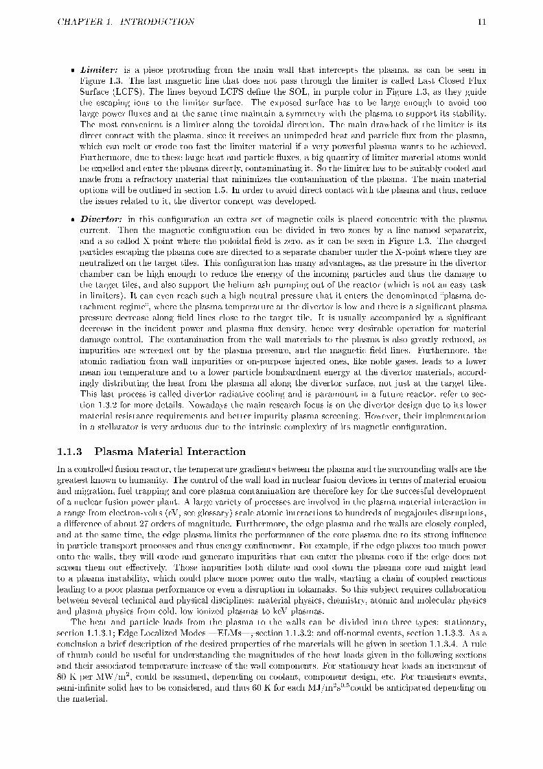
� Limiter: is a piece protruding from the main wall that intercepts the plasma, as can be seen inFigure 1.3. The last magnetic line that does not pass through the limiter is called Last Closed FluxSurface (LCFS). The lines beyond LCFS de�ne the SOL, in purple color in Figure 1.3, as they guidethe escaping ions to the limiter surface. The exposed surface has to be large enough to avoid toolarge power �uxes and at the same time maintain a symmetry with the plasma to support its stability.The most convenient is a limiter along the toroidal direction. The main drawback of the limiter is itsdirect contact with the plasma, since it receives an unimpeded heat and particle �ux from the plasma,which can melt or erode too fast the limiter material if a very powerful plasma wants to be achieved.Furthermore, due to these large heat and particle �uxes, a big quantity of limiter material atoms wouldbe expelled and enter the plasma directly, contaminating it. So the limiter has to be suitably cooled andmade from a refractory material that minimizes the contamination of the plasma. The main materialoptions will be outlined in section 1.5. In order to avoid direct contact with the plasma and thus, reducethe issues related to it, the divertor concept was developed.
� Divertor: in this con�guration an extra set of magnetic coils is placed concentric with the plasmacurrent. Then the magnetic con�guration can be divided in two zones by a line named separatrix,and a so-called X-point where the poloidal �eld is zero, as it can be seen in Figure 1.3. The chargedparticles escaping the plasma core are directed to a separate chamber under the X-point where they areneutralized on the target tiles. This con�guration has many advantages, as the pressure in the divertorchamber can be high enough to reduce the energy of the incoming particles and thus the damage tothe target tiles, and also support the helium ash pumping out of the reactor (which is not an easy taskin limiters). It can even reach such a high neutral pressure that it enters the denominated �plasma de-tachment regime�, where the plasma temperature at the divertor is low and there is a signi�cant plasmapressure decrease along �eld lines close to the target tile. It is usually accompanied by a signi�cantdecrease in the incident power and plasma �ux density, hence very desirable operation for materialdamage control. The contamination from the wall materials to the plasma is also greatly reduced, asimpurities are screened out by the plasma pressure, and the magnetic �eld lines. Furthermore, theatomic radiation from wall impurities or on-purpose injected ones, like noble gases, leads to a lowermean ion temperature and to a lower particle bombardment energy at the divertor materials, accord-ingly distributing the heat from the plasma all along the divertor surface, not just at the target tiles.This last process is called divertor radiative cooling and is paramount in a future reactor, refer to sec-tion 1.3.2 for more details. Nowadays the main research focus is on the divertor design due to its lowermaterial resistance requirements and better impurity plasma screening. However, their implementationin a stellarator is very arduous due to the intrinsic complexity of its magnetic con�guration.
1.1.3 Plasma Material Interaction
In a controlled fusion reactor, the temperature gradients between the plasma and the surrounding walls are thegreatest known to humanity. The control of the wall load in nuclear fusion devices in terms of material erosionand migration, fuel trapping and core plasma contamination are therefore key for the successful developmentof a nuclear fusion power plant. A large variety of processes are involved in the plasma material interaction ina range from electron-volts (eV, see glossary) scale atomic interactions to hundreds of megajoules disruptions,a di�erence of about 27 orders of magnitude. Furthermore, the edge plasma and the walls are closely coupled,and at the same time, the edge plasma limits the performance of the core plasma due to its strong in�uencein particle transport processes and thus energy con�nement. For example, if the edge places too much poweronto the walls, they will erode and generate impurities that can enter the plasma core if the edge does notscreen them out e�ectively. Those impurities both dilute and cool down the plasma core and might leadto a plasma instability, which could place more power onto the walls, starting a chain of coupled reactionsleading to a poor plasma performance or even a disruption in tokamaks. So this subject requires collaborationbetween several technical and physical disciplines: material physics, chemistry, atomic and molecular physicsand plasma physics from cold, low ionized plasmas to keV plasmas.
The heat and particle loads from the plasma to the walls can be divided into three types: stationary,section 1.1.3.1; Edge Localized Modes �ELMs�, section 1.1.3.2; and o�-normal events, section 1.1.3.3. As aconclusion a brief description of the desired properties of the materials will be given in section 1.1.3.4. A ruleof thumb could be useful for understanding the magnitudes of the heat loads given in the following sectionsand their associated temperature increase of the wall components. For stationary heat loads an increment of80 K per MW/m2, could be assumed, depending on coolant, component design, etc. For transients events,semi-in�nite solid has to be considered, and thus 60 K for each MJ/m2s0.5could be anticipated depending onthe material.
CHAPTER 1. INTRODUCTION 12
1.1.3.1 Stationary heat and particle loads
Regular operation of a plasma device implies the necessity to dissipate the power entering the SOL from theplasma core, 10-15 MW in the largest machines like JET . As the SOL is very thin, the power is translatedin a parallel heat �ux up to 500 MW/m2 with a width of 5 mm that is directed to the �strike point� (seeglossary), where the separatrix intersect the divertor target tiles (see glossary). This huge heat �ux on thedivertor plates must be reduced bellow the technological feasible perpendicular heat �uxes. For actively cooledsurfaces it is in the order of 10 MW/m2. Several strategies are used in present machines to maximize the areawhere power is loaded to: poloidally inclining the divertor tiles, optimizing the divertor coils to increase themagnetic �ux expansion and broadening the SOL heat �ux width through increased perpendicular transport.A factor of 10 is expected in ITER, 4 from magnetic �ux expansion and 2.5 from target inclination (however,recent calculations point to a very reduced loaded area, around 4 mm, at some conditions like non-detachedor attached mode at the divertor [4]). In addition, extrinsic gas impurities like neon, argon and nitrogen canbe introduced to increase the capability of the divertor to radiate power (radiative cooling, see section 1.3.2).The necessary radiated power in ITER will be much larger than in present machines, around 50% of the totalpower.
At the main wall, due to the SOL heat and particle �ux, the gas density is between 30 and 300 timeslower than at the divertor. Thus the power loads at the main walls compromise mostly plasma and divertorgas radiation, leading to an uniform power loading pro�le. For example, for ITER half of the total power willbe radiated onto the walls leading to a power density of only 0.11 MW/m2, easily extracted through watercooled panels. However, great care must be taken when selecting the main wall material in order to reduceplasma core contamination due to their proximity and di�cult impurities screening, as will be explained insection 1.3.1.
1.1.3.2 Edge Localized Modes (ELMs)
ELMs are magnetohydrodynamic related periodic events that occur during a regime of enhanced globalenergy con�nement denominated high con�nement mode. The so-called H-mode is a regime of operationspontaneously attained when the auxiliary heating power is high enough, mainly in divertor devices. AlthoughH-mode is also possible in tokamaks or stellarators without divertors, it is more di�cult to achieve at thosedevices. A sudden improvement in particle con�nement time (a factor of 2) is detected, leading to increaseddensity and temperature in the core, separating this mode from the normal low mode or �L-mode�. This makesthe H-mode a desirable operation regime, specially for ITER and future nuclear fusion reactors. However,the processes involved in it are not completely understood, and thus object of deep study. It is known thatsuch particle con�nement improvement is originated by the development of a so-called transport barrier atthe edge of the plasma which greatly reduces the transport to the SOL and cause an abrupt step or �pedestal�in the temperature and density pro�les, in a process similar to an accumulation of energy at the edge. ELMsinvolve very rapid expulsion of energy and particles from the edge of the plasma into the SOL and cantransiently reduce the temperature and density in this region, decreasing the pedestal, and thereby a�ectthe core con�nement. They play a bene�cial part as they help the expulsion of core plasma impurities thatusually accumulate at the edge in H-mode. Nevertheless, depending of the ELM type, they can carry up to15% of the energy accumulated in the pedestal, large enough to melt or quickly erode the divertor tiles. Thephysics of how the ELM energy reaches the divertor and wall is still too uncertain for modeling the heat �uxreaching those surfaces, but experimentally it has been observed that up to half of this energy is transportedoutside of the divertor. They are mainly two types of ELMs that are studied for ITER H-mode regimes, butalso some other regimes without ELMs, or with controlled ELM frequency are good candidates.
� Type I or giant ELMs: they are the most usual in H-mode. They have a low frequency, 0.5-2 Hz, butlarge energy, up to 0.6 MJ in present machines and 8-20 MJ for ITER. However, the timescale of theheat load at the wall tiles is only about 0.1-1 ms, so a semi-in�nite solid heat transfer model has tobe used, as thermal equilibrium is in the range of some seconds. Therefore the power deposited on thedivertor tiles could be in the order of 1 GW/m2, or 120 MJ/m2s0.5, more than enough to ablate or meltthe surface, about 40-50 MJ/m2s0.5 for most refractory materials. In current machines the temperatureexcursion is around 2500 °C during the ELM. On the other hand, the con�nement achieved in type IELMs H-mode is the highest.
� Type III ELMs: prevalent in regimes with highly radiative, detached divertor operation (achieved whenimpurity radiation at the edge is very high, usually from external impurities injection, see section 1.3.2)and external heating power near the threshold necessary for H-mode transition. They have a highfrequency, 1 kHz, and thus low energy, in the order of 0.1 % of the pedestal energy, few kJ for presentmachines and up to 0.3 MJ in ITER. More than 70-80% of the ELM power is radiated, even 97 %

CHAPTER 1. INTRODUCTION 13
has been achieved in steady state. In this regime the heat loads at the divertor tiles are very low,<1 MJ/m2s0.5, with temperature increments of 10 °C in present machines. However, due to the highimpurity levels at the edge the con�nement loss lies between 10 and 30 % with respect to the type IELMs H-mode, but the divertor material lifetime improvement could worth this loss.
� ELM free: They are a group of H-mode regimes with di�erent parameters. They are usually di�cult toachieve and are not observed at all experimental nuclear fusion device. Furthermore, they reduce toomuch the con�nement compared to type I ELM H-mode, and are thus not included in the main ITERdesign. They include: quiescent H-mode, enhanced D-Alpha, electron cyclotron heating at the edge,etc. Another special regime consist in using in-vessel coils to apply resonant magnetic perturbation onthe plasma edge. In this way the plasma edge is ergodized (chaotic �eld lines are generated) leading toa mitigation or even suppression of ELMs. These in-vessel coils have already been designed for ITER,although the physics of boundary ergodization are not completely understood as they vary considerablyfrom one device to another. For example in some devices, like DIII-D in San Diego U.S.A., density andtemperature in the plasma core are increased in the �rst moments, but need an active feedback control.
� ELM pacing: they are a group of techniques that are used in type-I ELM regime which are able totrigger an ELM in a controlled way, thus increasing the frequency (even a factor of 15-30) and reducingthe ELM energy. They include the application of short plasma vertical displacements (kicks), andfrozen deuterium pellets injection as most of them trigger an ELM around 0.2 ms after.
1.1.3.3 O�-normal events: disruptions
All existing tokamaks are subjected to occasional rapid plasma termination events, called disruptions. Inlarge size machines disruptions have already caused signi�cant damage, such as melting or signi�cant erosionof plasma facing components, short circuits in external supplies and deformation of in-vessel structures. Infuture nuclear fusion devices, such as ITER, the problems will be more serious, as heat loads and forces will beup to two orders of magnitude larger. Disruptions can generally be divided into two basic categories: majordisruptions and loss of equilibrium control by vertical displacement events (VDEs) leading to a disruption.
� Major disruption : the plasma becomes unstable as a result of reaching an operational limit, indensity or plasma pressure, which leads to the growth of a large magnetohydrodynamic mode. Thismay be initiated for many reasons, e.g. a small piece of material falling into the plasma, where theresulting rapid cooling of the plasma periphery can result in an unstable plasma. The large MHDactivity breaks the nested magnetic �eld surfaces. Thermal energy is rapidly lost, and the currentpro�le �attens, causing a drop in the plasma inductance (the source of the poloidal �eld generation)and a corresponding upward spike in the current. Finally, the high resistivity of this cold plasma resultsin a rapid decay of the plasma current, �nishing in a VDE where part of the magnetic energy is lost tothe main wall. The thermal loss transfers most (80-100%) of the total plasma energy into the divertorwalls. The heat loads are indeed very large and occur in a short timescale of 1-10 ms, meaning 10-150GW/m2, or up to 2 GJ/m2s0.5 in ITER. This huge heat load is more than enough to severely melt andablate a large part of the divertor tiles. But also the tokamak structure su�ers during the VDE followingthe disruption due to the formation of �halo� currents from the plasma current (up to 100%). They �owalong open �eld lines surrounding the plasma intersecting the vessel wall and return poloidally throughconducting components of the vessel structures. The �ow of this return current will be perpendicularto the main magnetic �eld, thus exerting a large mechanical force on these structures. Disruptions inITER are predicted to be around 10 % of the total pulses.
� Loss of equilibrium VDE , the results are similar to disruptions but the sequence is di�erent. The�rst event is a loss of the vertical position, and the plasma moves vertically with the cross-section andthe poloidal magnetic �eld decreasing as the plasma scrapes o� against the main wall. The plasmathen disrupts: thermal energy is �rst loss (typically, there is no current spike), followed by a plasmacurrent decay. This VDEs can place the heat loads in a di�erent part of the divertor than stationaryloads, or other disruptions and ELMs, or even in the upper part of the reactor. Consequently theseparts are less protected against so heavy heat loads and the damage could be catastrophic, specially inthe upper part as the materials are usually not (so) refractory. This kind of VDE is predicted to a�ect1% of ITER pulses, but even so they could cause such a severe damage that, in order to prevent it, thein-vessel coils will have to be used for a fast active feedback realignment of the plasma.
Hence, all disruptions in ITER must be predicted in real time and mitigated to reduce the impact on theplasma facing components. The usual mitigation technique is a massive gas injection (MGI) that cools downthe plasma quickly by dilution and radiation (mostly deuterium or hydrogen, but also 5-10 % of a good

CHAPTER 1. INTRODUCTION 14
radiator atom as Argon has to be added). Nowadays the prediction codes only act over the MGI valve,but great progress has been made towards active feedback through identifying the disruption origin anddetermining how to control it in order to avoid losing the pulse.
1.1.3.4 Plasma facing materials desired properties
The materials to be used in a nuclear fusion reactor must be compatible with ultra-high vacuum, cryogenicsbecause of cryopumps, magneto-hydro dynamics, neutron irradiation and handling of large particle and heatloads. As a consequence, the selected materials are subject to strict properties requirements: high thermaland electrical conductivity, good thermomechanical properties and resilience against thermal shocks, lowplasma contamination due to line radiation in the core, low neutron activation and resistance to radiationdamage, low retention and low chemical a�nity of hydrogen isotopes. Also high a�nity to air molecules,oxygen and nitrogen, leading to the formation of stable and non-volatile compounds, is also important forimpurity gettering to reduce plasma contamination and material sputtering. Unfortunately, no materialcould satisfy all these requirements, only a few could be considered. Their advantages and drawbacks will betreated in section 1.5.
1.1.4 Future projects design: ITER and beyond
Much of the signi�cant progress in magnetic fusion science has been made in the tokamak concept, whichhas represented the main approach to magnetic con�nement fusion. In current tokamaks, improvements ofplasma performance and control have occurred owing to remarkable advance in several areas of physics andengineering. For example, superconducting coils have allowed long pulses supporting the achievement of asteady state operation regime, for example, in TRIAM-1M pulses of 2 hours were achieved using non-inductivecurrent drive, although at low density and low power discharges. These advances lead to the development ofregimes of operation, with both good con�nement and magnetohydrodynamic stability, which have enabledthe production of fusion power from deuterium-tritium plasmas in the tokamaks TFTR (11 MW) and JET(16 MW). So the next step is to demonstrate a safe and economic reactor operation in long discharges witha burning plasma, where more energy is produced by nuclear fusion than the energy necessary to maintainit. This is the main objective for ITER, but it also will provide a test facility for the development of nuclearcomponent technology, which will be extrapolated to a fusion reactor prototype, DEMO. An example are thebreeding blankets (see glossary), which will surround the main wall to produce enough tritium from the reac-tion of lithium with the fusion neutrons to replenish the consumption and losses. But they are also essentialbecause they stop neutrons extracting their heat to generate electricity and protecting other vulnerable partslike electronic and superconducting coils from them.
However, there are some essential di�erences between today's tokamak research facilities and ITER. Theincrease in pulse duration and cumulative run time, together with the increase in plasma energy content, willrepresent a true challenge for the materials lifetime, not only for short heavy heat and particle loads, butalso in long term erosion and fatigue, as it will be explained in section 1.2. On the other hand, erosion of thereactor walls is not an issue for current tokamak devices in terms of component lifetime, but poses a problemas a source of impurities in the plasma, and it will be also a serious problem for ITER and new stellaratorslike Wendelstein-7X, as explained at section 1.3. Similarly, fuel economy has never been an issue in deuteriumexperiments at present devices, but the incomplete recovery of tritium in TFTR and JET experiments in the90's has placed the tritium retention in the vessel as one of the main issues, as covered in section 1.4. Themain materials used at the �rst wall for present devices, or planned for near-future ones as ITER and fornuclear fusion reactor designs will be reviewed in section 1.5. Finally, the objectives of this thesis applied forITER plasma facing materials will be depicted in section 1.6.
1.2 MATERIAL DAMAGE IN A NUCLEAR FUSION REACTOR
The temperature of the plasma con�ned in a nuclear fusion reactor reaches several million degrees, but even atthe very low densities of them�of up to one million times less than atmosphere� it could damage irreversiblythe surrounding walls, usually called Plasma Facing Components (PFC). There are many di�erent sourcesof damage as erosion in steady state, erosion during o�-normal events, due to neutron irradiation, particlesimplantation, etc. In current reactors this damage is usually not an issue, but in ITER the plasma will have athermal energy 20 times larger than the current biggest device, JET tokamak, along with a much longer pulseoperation (400 s compared to 10 s in JET, although other smaller devices with superconducting magnets likeTore Supra in France can operate during similar times). Furthermore, in a power plant reactor like DEMO,

CHAPTER 1. INTRODUCTION 15
neutron irradiation will also be an issue. Erosion of wall materials limits the lifetime of the wall components,and, at the same time, it is the source of other problems in the reactor. For example, these eroded materialscould enter the plasma core diluting and cooling it down, section 1.3, or be deposited elsewhere creating aproblem of dust generation and/or fuel retention, section 1.4.
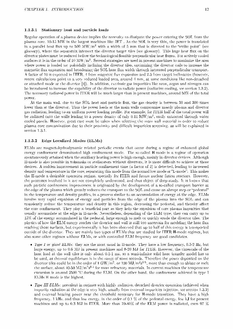
(a) Macrobrush (b) Monoblock
Figure 1.4: First wall tungsten armor designs for ITER divertor
Current estimations of wall lifetime for ITER are based on extrapolations from present experiments ormodeling calculations that imply (relatively) large uncertainties. They can give an idea of the number ofpulses before reaching a limit in erosion, mechanical strength, etc., but some limits could be reached afteronly several tens of discharges. Consequently, it is paramount to reduce that damage by means of a carefuldesign of the device components and operation scheme, but mainly by means of a thoughtful material choice,refer to section 1.5 for more details. However, all those designs are linked, and what could be good againstthermal loads, could be bad in other terms. For example, the tiles are divided in castellations against thermalshocks like in Figure 1.4, but that causes other problems like formation of codeposits of eroded material withnuclear fuel inside the gaps. In this way a large amount of tritium could be trapped in a di�cult to reacharea. This issue could be diminished through a careful operation of the device, by selecting a material whichdoes not originate codeposits with fuel, or developing removal methods inside these gaps, refer to section 1.4for more details.
The main types of damage for the plasma facing components will now be addressed: �rst the erosion byphysical and chemical sputtering in sections 1.2.1 and 1.2.2 respectively; followed in section 1.2.3 by thermaldamage like melting; neutron radiation will be treated in section 1.2.4; other types of damage like blisteringwill be enumerated in the last section 1.2.5.
1.2.1 Erosion by physical sputtering
When a projectile, energetic ion or neutral, impacts on a target material, it transfers its momentum (energyand mass) to the surface atoms. Depending on the projectile momentum there are mainly 4 processes fromlower to larger energy: backscattering of the projectile; ion-induced desorption of adsorvates and emissionof electrons and photons from the target; ejection of atoms from the target via nuclear collision with theprojectile �sputtering�; and projectile implantation into the target. During physical sputtering, if theprojectile momentum is large enough to overcome the surface binding energy, a surface atom may be ejectedfrom the material. The �rst collisions will direct the target atoms into the surface, but subsequent collisionswith other projectiles or between surface atoms (in a cascade regime) can direct some of them out of thesurface. This process is depicted in Figure 1.5 where it is shown that, depending on its momentum, theprojectile might be implanted into the solid or simply backscattered. The sputtered compounds are mostlyneutral atoms, but ions and small clusters of the target material may also be ejected. However, as theprojectile momentum has to overcome the surface binding energy, there will exist a threshold energy bellowwhich the sputtering yield is zero.
In order to characterize the erosion by physical sputtering, a yield (YPhys) is de�ned as the ratio of theaveraged number of sputtered atoms for each incoming projectile. This sputtering yield will depend on themomentum transfer between projectile and surface. It will thus depend on the impact energy and angle,and the atomic mass ratio between the projectile and the target atoms. It is important to note that thesputtering yield does not depend signi�cantly on the surface temperature.
� Impact energy: for impact energies above the threshold the sputtering yield increases steadily withthe energy transferred to the surface atoms until reaching a maximum. Further increase of the impactenergy results in a slow decrease of the sputtering yield as the impinging projectiles penetrate deeperinto the solid generating collisions cascades further from the surface, and thus less energy is transmitted

CHAPTER 1. INTRODUCTION 16
Figure 1.5: Physical sputtering process of surface atoms by a projectile
to the surface atoms to be sputtered. Nonetheless, the mechanical properties of both the bulk materialand the surface will be degraded. In a plasma the impact energy of ions is determined by the ion andelectron temperature (Ti and Te, respectively) by this equation: E ∼ 3 ·Q · Te + 2 · Ti, where Q is thecharge state of the ion. The �rst part of the equation originates from the acceleration of the ions in thesheath, and the second part correspond to the Maxwell distribution of the thermal velocity of ions.
� Impact angle and surface roughness: the larger the grazing incidence of the projectiles, the more energywill be transferred to the surface atoms. After reaching a maximum, usually between 70 and 80°, thesputtering yield su�ers a strong decrease as the projectiles are more e�ciently re�ected. The roughnessof the surface can change the local angle of incidence, and the sputtered atoms can be redepositedat the side walls of the valleys of a rough surface. Therefore, the roughness could lower considerablythe dependence on the angle for larger nominal incidences and increase the erosion at near normalincidences.
� Atomic mass ratio, self-sputtering and preferential sputtering: the momentum transfer is maximum foridentical masses of projectile and surface atoms and so is the sputtering yield. This process, calledself-sputtering, could be very important in magnetic con�nement fusion plasmas when a material issputtered by its own returning ions due to the applied magnetic �eld. In some cases the value of thesputtering yield could be larger than one if the ion energy is high enough, meaning that it could causea catastrophic chain reaction. For very di�erent combinations of projectile and target atoms mass,the sputtering yield could be greatly reduced. For this reason when the target is not a monoatomicmaterial (like stainless steel) the atoms most mass-matched with the projectile will su�er a preferentialsputtering, and consequently the surface will gradually become relatively rich on poorly mass-matchedatoms.
Therefore as the nuclear fusion plasma is made of very light atoms (hydrogen isotopes), for reducing theerosion it could be very interesting to use high Z materials (for example the threshold energy for tungstensputtering by deuterium is around 200 eV, while for beryllium is around 10 eV). However, these high Z atomscan pose serious operation problems if they enter the plasma core because their large line radiation wouldcool down the plasma decreasing its e�ciency and even leading to disruptions, refer to section 1.3 for moredetails.
1.2.2 Erosion by chemical sputtering
Chemical sputtering is de�ned as a process where, due to ion bombardment, a chemical reaction occursor is highly enhanced, and where a clear synergism takes place between physical sputtering and chemicalerosion. It involves the creation of broken or dangling bonds at the surface by the impinging ions, whichreact with the same thermalised ions or other neutral compounds to form a volatile molecule which canbe desorbed into the gas by the ion bombardment itself (typically at ∼1eV). Chemical sputtering appearsonly for certain combinations of target material, impinging atoms and/or gas, when the species involved arechemically reactive. A classical example in nuclear fusion are carbon material erosion by hydrogen isotopes,as will be explained at the next point. Impact energy and surface temperature are the main parameters inchemical sputtering yield (Ychem.sp) but there is also an incoming particle �ux dependence.

CHAPTER 1. INTRODUCTION 17
� Impact energy: the dependence is much lower than for physical sputtering, but qualitatively similar.The exception is that the threshold energy is usually very low, in the order of 2 eV.
� Surface temperature: as any chemical reaction, the chemical sputtering has a great temperature de-pendence. It increases with temperature, but many times it has a maximum where the erosion-relatedreaction is hampered, for example by the formation of a passivating layer, or because another reactionbecomes more important.
� Ion �ux: data from various experiments in ion beam devices, linear plasma machines and nuclear fusionexperiments show a yield reduction in the yield for very large �uxes, for carbon-hydrogen is around1021 H+/m2s. This e�ect seems to be related to the increase of the surface temperature due to strongion bombardment, and hence, as commented in the previous point, the development of another non-erosion related reaction. A displacement in the thermodynamic equilibrium of the reaction towards thereactants like the generation and release of molecular hydrogen could also be the cause of this e�ect.The initial surface temperature has been found to have an e�ect in the �ux dependence.
1.2.2.1 Hydrogen chemical sputtering of carbon materials
Carbon materials, like graphite and Carbon Fibre Composites �CFC�, present a large chemical sputteringby hydrogen isotopes. Plasma-generated hydrogen radicals react towards molecular, or radical, hydrocarbonsby chemical erosion, or from dangling bonds created previously by impinging hydrogen ions or any other ions(wall materials, helium, and other impurities). The atomic description of the chemical erosion is presentedin Figure 1.6. First sp2 bonded carbon is hydrogenated to sp3 via an intermediate spx (bottom and left-hand side of Figure 1.6). Further hydrogen radical bombardment leads to the desorption of H2 through theintermediate spx (top of Figure 1.6). Finally, if the surface temperature is larger than 400 K, the chemicalerosion can continue via desorption of hydrocarbon complexes, closing the cycle at the initial step with sp2
bonding. At temperatures larger than 600 K, the intermediate state spx starts to dehydrogenate towards sp2,therefore decreasing the chemical erosion. Accordingly, the chemical bonding at the surface of the carbonmaterial determines its chemical erosion rate. For example, diamond, sp3 with very strong bonds closed atthe surface, presents an erosion rate one order of magnitude lower than graphite, sp2; and more than threeorders of magnitude lower than high-hydrogen amorphous hydrocarbon called soft a-C:H , with a largecontent of reactive spx bonds. On the other hand, ion bombardment creates dangling bonds which reducethe disparities among di�erent carbon materials, i.e. diamond erosion is largely enhanced whereas soft a-C:His not so much.
Figure 1.6: Atomistic process of chemical erosion of carbon by hydrogen
The main species released from the surface during chemical erosion by hydrogen are CH3· (and hence CH4
by further reaction with hydrogen), C2Hy, and C3Hy in a relative proportion of 1:0.8:0.5. The maximumproduction of high order hydrocarbons happen at lower temperatures, between 520 and 650 K. When thereis ion bombardment, the product release process becomes completely di�erent, as now the molecules areion-induced desorbed before they are fully developed. In general, higher order hydrocarbons are producedpreferentially at lower bombardment energies. C2H2 and C2H4 production is dominant over CH4 under 1 keV,while C2H6 and C3Hy production is greatly reduced compared to pure chemical erosion, and their maximum

CHAPTER 1. INTRODUCTION 18
lies between 200 and 400 eV, except for C3H4 where it lies at 800 eV. However, a �uence dependence of afactor 3-4 lower has been found for C2Hy formation, although its quanti�cation remains unresolved. In afusion reactor, these hydrocarbons released from the surface, stable or radicals, can be ionized and/or brokenwithin the plasma into more reactive species, and thus develop amorphous hydrocarbon �lms elsewhere.This last process generates codeposits of carbon with hydrogen isotopes, i.e. fuel, in di�cult-to-reach places,which will be the main drawback of carbon-related materials. This severe problem will be approached insection 1.4.2.
1.2.2.2 Chemical sputtering of carbon materials by other reactive species
Carbon materials can also su�er chemical sputtering by other species. The most important ones for nuclearfusion are oxygen and nitrogen. They could be unintended present from air leaks, leading to an undesirederosion of wall tiles, or injected on purpose to eliminate the codeposits of carbon and hydrogen isotopes(a-C:H) due to their high reactivity, refer to section 1.4.3 for full details.
� Oxygen: his strong reaction with carbon materials producing CO and CO2 is well-known. The ionbombarding energy dependance is weak for values between 50 eV and 10 keV, being the yield of 0.7-1C atoms eroded by impinging O atom, two orders of magnitude larger than hydrogen. The di�erenttypes a-C:H are far more reactive and the yield is usually 10 to 50 times larger than for pure carbon.This huge yield is explained by the simultaneous production of CO, CO2, H2O, hydrocarbons, etc.
� Nitrogen: its reaction with carbon materials to produce C2N2 is also well-known. The ion bombardmentenergy dependance is again weak: between 50 eV and 1 keV the yield is approximately 1 C atom for eachincident N atom (comparable to oxygen). Now the yield from a-C:H �lms and pure carbon materials isalmost the same except for the more reactive soft a-C:H �lms (high H content). Furthermore, a clearsynergistic e�ect is seen when atomic hydrogen is injected, as the yield increases 3 to 7 times, due tothe large number of broken bonds caused by the large momentum transfer between nitrogen and carbonatoms. The enhanced reaction to hydrogenated carbon-nitrogen products plays an important role aswell, being HCN the main product, but also CH3CN, NH3, hydrocarbons, etc.
1.2.2.3 Total yield
The total erosion, or yield (Y), is determined as the �ux of eroded particles divided by the �ux of incomingprojectiles. It is the sum of the physical sputtering and chemical sputtering (if existing). A clear exampleof both processes on graphite can be found in Figure 1.7. It can be seen how the experimental values(squares) at lower energies are quite large and do not match the physical sputtering model (red line). Whena chemical sputtering model (blue lines) is added, then the experimental data are well represented (greenline). It is possible to extract some conclusions for carbon erosion by hydrogen as well: total yield is fairlyindependent from bombardment energy except for very large values; and chemical sputtering is prominent atlow bombardment energies, while at energies above 1 keV only physical sputtering has an e�ect.
Figure 1.7: Total sputtering yield of graphite by hydrogen isotopes as a sum of chemical and physical sputtering.

CHAPTER 1. INTRODUCTION 19
1.2.3 Melting and evaporation
Refractory materials like tungsten and graphite are usually chosen for those places where the largest heat loadsare expected. For example, in ITER considering a heat �ux of 5 MW/m2 to the divertor tiles during steadystate, a temperature increase of 400 K can be estimated, easily handled by the proposed heat sink designs: seeexamples in Figure 1.4. Although melting and evaporation of plasma facing materials could occur in steadystate if a heat sink fails, or due to a coolant failure, they would take place during unmitigated type-I ELMsand o�-normal events like disruptions due to their short-timescale heat deposition. The temperature increasefor unmitigated Type I ELMS could reach 9,600K, and for disruptions 16,000 K, refer to sections 1.1.3.2 and1.1.3.3 for more details. In ITER the number of these events could be very high during H-mode operation,and also 10% of the pulses during normal operation will �nish in a disruption. Hence a characterization ofthe behavior of divertor materials under heavy transitory heat loads is mandatory.
In metals, the melt layer developed could be in the tens of microns, and will be exposed to various forcessuch as electromagnetism, gravitation, mechanical vibration, plasma momentum, surface tension and ablationrecoil. All these forces leads to the almost completely loss of the melted layer in mainly two ways:
� Horizontal melt layer motion caused by current decay in the liquid metal layer in combination withthe strong magnetic �eld producing destabilizing Lorentz forces. This process can lead to a bridgingof adjacent castellations, and thereby increasing electromagnetic (eddy current) forces, making moresusceptible to thermal shocks, etc.
� Droplet ejection (aerosol) due to build-up of vapor bubbles inside the liquid layer, and to the increaseof hydrodynamic instabilities caused by the plasma impact momentum at the liquid surface. Thesedroplets could also bridge castellations, but the main problems are the possibility that they could enterthe plasma leading to a disruption, and dust generation, which could be radioactive and/or containtrapped fuel.
The amount and rate of melt layer loss is di�cult to predict as it depends on many parameters, such as heat�ux, impurity and gas content, material properties and disrupting plasma parameters. Getting to know theconsequences of the melting, both on the material itself and on the capacity to maintain plasma operation ondamaged surfaces is paramount. Devices like plasma guns could simulate the conditions during a disruptionthermal quench in ITER. However, those conditions are not completely ful�lled: expected plasma pressure inITER is at least one order of magnitude lower; and neither glancing angles of incidence nor strong magnetic�elds are possible in plasma guns. In Figure 1.8 the melting of tungsten macrobrush tiles at two di�erentpulse conditions in the Quasi-Stationary Plasma Accelerator (QSPA) SRC RF TRINITI are shown. At apower in the order of ITER-like type-I ELMs, Figure 1.8b, the castellations are fully bridged and the tileis rendered useless after only 10 pulses [5]. If lower powers are used, but in the order of ITER-like type-I ELMs, the melting process can be monitored, see Figure 1.8c and 1.8d for a more detailed picture. Acrack network appear because of fatigue. Then melting starts in any leading edge due to their lower heatconduction geometry, like those projecting cracks and at the plasma-facing edge of the macrobrush. In orderto reduce this e�ect, a �sh-scale con�guration has been selected for ITER divertor tiles, where the leadingplasma-facing edge of each castellation is shadowed by the previous one.
On the other hand, evaporation losses of metallic plasma facing components are generally smaller, onlya few micrometres, about one order of magnitude lower than melting loses. This is combined with a processcalled vapor shielding. When the heat �ux is too large and the metal start to be vaporized, it develops acloud of vapor just in front of the material, which is heated and ionized by the incoming plasma, and becomescon�ned by the magnetic �eld. The incoming plasma particles are then stopped in the vapor plasma, andits energy is radiated in all directions by the vapor atoms (usually high Z, so large line radiation). In thisway the incoming energy towards the metal tile is greatly reduced when a really huge heat �ux impacts onthe surface. The parameters and the dynamics of vapor shielding depend on the energy �ux and the type oftarget material. A low Z target plasma (e.g. C, Be) expands to larger distances from the surface, whereasvapor shields formed from higher Z materials (e.g. W, Mo) stay closer to the surface.
Since carbon materials (graphite, CFC) sublimate, they o�er a great advantage over most materials. Asthey do not melt, the material loss during large heat loads is greatly reduced, aided by the vapor shieldingas well. They also do not su�er from castellation bridging, melt splashing, etc. However, they have anotherproblems like brittle destruction over a determined energy threshold (e.g. 148 MJ/m2s0.5 for isotropic �negrain graphite). This process consists on the generation of thermally induced microcracks at the surfaceleading to the ejection of carbon dust particles, and dramatically increased erosion.
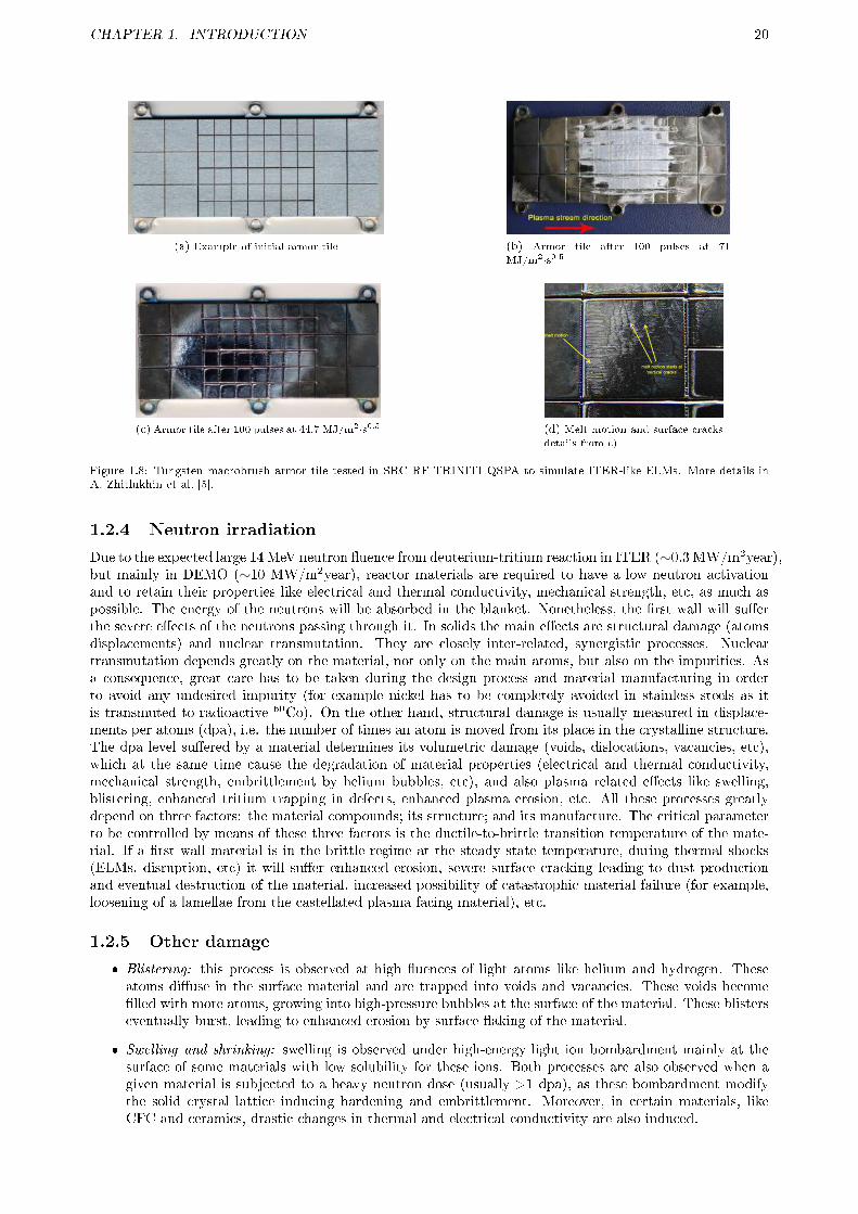
CHAPTER 1. INTRODUCTION 20
(a) Example of initial armor tile (b) Armor tile after 100 pulses at 71
MJ/m2·s0.5
(c) Armor tile after 100 pulses at 44.7 MJ/m2·s0.5 (d) Melt motion and surface cracks
details from c)
Figure 1.8: Tungsten macrobrush armor tile tested in SRC RF TRINITI QSPA to simulate ITER-like ELMs. More details inA. Zhitlukhin et al. [5].
1.2.4 Neutron irradiation
Due to the expected large 14 MeV neutron �uence from deuterium-tritium reaction in ITER (∼0.3 MW/m2year),but mainly in DEMO (∼10 MW/m2year), reactor materials are required to have a low neutron activationand to retain their properties like electrical and thermal conductivity, mechanical strength, etc, as much aspossible. The energy of the neutrons will be absorbed in the blanket. Nonetheless, the �rst wall will su�erthe severe e�ects of the neutrons passing through it. In solids the main e�ects are structural damage (atomsdisplacements) and nuclear transmutation. They are closely inter-related, synergistic processes. Nucleartransmutation depends greatly on the material, not only on the main atoms, but also on the impurities. Asa consequence, great care has to be taken during the design process and material manufacturing in orderto avoid any undesired impurity (for example nickel has to be completely avoided in stainless steels as itis transmuted to radioactive 60Co). On the other hand, structural damage is usually measured in displace-ments per atoms (dpa), i.e. the number of times an atom is moved from its place in the crystalline structure.The dpa level su�ered by a material determines its volumetric damage (voids, dislocations, vacancies, etc),which at the same time cause the degradation of material properties (electrical and thermal conductivity,mechanical strength, embrittlement by helium bubbles, etc), and also plasma related e�ects like swelling,blistering, enhanced tritium trapping in defects, enhanced plasma erosion, etc. All these processes greatlydepend on three factors: the material compounds; its structure; and its manufacture. The critical parameterto be controlled by means of these three factors is the ductile-to-brittle transition temperature of the mate-rial. If a �rst wall material is in the brittle regime at the steady state temperature, during thermal shocks(ELMs, disruption, etc) it will su�er enhanced erosion, severe surface cracking leading to dust productionand eventual destruction of the material, increased possibility of catastrophic material failure (for example,loosening of a lamellae from the castellated plasma facing material), etc.
1.2.5 Other damage
� Blistering: this process is observed at high �uences of light atoms like helium and hydrogen. Theseatoms di�use in the surface material and are trapped into voids and vacancies. These voids become�lled with more atoms, growing into high-pressure bubbles at the surface of the material. These blisterseventually burst, leading to enhanced erosion by surface �aking of the material.
� Swelling and shrinking: swelling is observed under high-energy light ion bombardment mainly at thesurface of some materials with low solubility for these ions. Both processes are also observed when agiven material is subjected to a heavy neutron dose (usually >1 dpa), as these bombardment modifythe solid crystal lattice inducing hardening and embrittlement. Moreover, in certain materials, likeCFC and ceramics, drastic changes in thermal and electrical conductivity are also induced.

CHAPTER 1. INTRODUCTION 21
� Arcing: they are electrical arcs of short duration (<1 ms) and high current density (1012 A/m=2),that can occur between the plasma, acting as anode, and a plasma facing material, acting as cathode.The arc is usually initiated in small surface protrusions, which provide a localized emission source. Inthese cases the material is evaporated and quickly eroded due to the signi�cant local heating causedby the arc. In the presence of an external magnetic �eld (typically parallel to the solid surface), theLorenz force favors the creation of a new arc on the edge of the initial crater. As a consequence, the arcjumps from one spot to another causing the common scratch-like signature of arcing (usually, severalmillimeters long).
� Thermal shocks: divertor modules are complex structures which consist of a castellated plasma facingmaterial over a CuCrZr actively-cooled heat sink with intermediate compliant and di�usion-barrierlayers. A really careful quality testing of the modules is mandatory to detect any fault on their di�erentparts. The continuous thermal shocks the module will be subjected to in a nuclear fusion device�mainly repetitive ones like ELMs and large-energy ones like disruptions�, will enlarge any defect.This will lead to hot spots, partial melting and catastrophic module failure (cooling water leak, looseningof part of the module armor, etc). Thermal shocks are specially harmful to brittle materials, so it is veryimportant to keep the material at sensible locations, like the divertor, in the ductile temperature range.However, in future fusion reactors this will not be easy due the large neutron-induced embrittlement(see section 1.2.4).
� Radiation Enhanced Sublimation (RES): it has been detected that, in carbon materials, the physicalsputtering yield increases exponentially from 1000 K. This e�ect seems to be caused by interstitialdefects induced by high energy ions. The interstitials not recombined with vacancies di�use towardsthe surface and sublimate into gas phase. Notwithstanding, this process has not yet been observed intokamaks, which is probably explained by their large, but low energetic, ion �uxes.
� Cracking by fatigue: plasma facing materials in a tokamak divertor are subjected to cyclic heat loadsand particle impacts during ELMs. There are many types of ELMs (refer to section 1.1.3.2 for detailsregarding their energy and frequency) but all of them would eventually lead to fatigue damage. Anexample of cracking by fatigue and induced melting is in Figure 1.8d.
� Dust production: dust particulates in tokamaks are produced by plasma erosion of plasma facing mate-rials in steady-state, and by most of the processes commented previously in this section, but dust is alsogenerated during the vacuum chamber conditioning, modi�cation, air venting, etc. Dust in a nuclearfusion device may be toxic, radioactive and/or chemically reactive due to its large speci�c surface. Thelatter point is specially important during water or air leaks because of the high explosion risk, whichcould lead to rupture of the vacuum vessel and dispersal of radioactive and toxic substances. Dustcan also be charged up during the plasma, and thus transported into the plasma core, cooling it byimpurity radiation (specially high Z materials), which can �nally lead to a disruption. In ITER, dustwill accumulate in di�cult-to-reach areas like under the divertor cassettes, so its elimination is notgoing to be an easy task. For these reasons the quantity of mobilizable dust will be limited in ITER to670 g.
1.3 PLASMA CONTAMINATION CONTROL
Since the �rst nuclear fusion experiments, contamination of the plasma core with impurities from the wall hasbeen a main concern. These impurities come mostly from the bombardment of the �rst wall with energeticplasma ions and neutrals. The atomic line radiation energy losses caused by the partial ionization of theseimpurities can hinder the plasma heating to the temperatures needed for the thermonuclear reactions tooccur. Furthermore, this process is subjected to a negative feedback: the more plasma energy is appliedby external heating or plasma self-heating, the more energy the wall bombarding particles have; and thusthe more wall sputtered impurities are produced and enter the plasma core. Finally these impurities radiateenergy in the plasma core, leading to plasma cooling instead of heating.
Another source of impurities are the residual gases inherent to any vacuum device: mainly nitrogen,oxygen and water. Nevertheless, the main concern for these impurities is the improved physical and chemicalsputtering of plasma facing materials they cause (refer to sections 1.2.1 and 1.2.2 for more details). Thein�uence of impurity contamination in the plasma core on the ability to reach the conditions for nuclearfusion, and the possibility to �nish the discharge in a disruption will be explained in section 1.3.1. On theother hand, the bene�cial, on-purpose injection of impurities to radiate in the plasma edge to reduce thethermal loads on the divertor walls will be approached in section 1.3.2.

CHAPTER 1. INTRODUCTION 22
1.3.1 Impurities contamination of plasma core
The line energy radiated from the impurities depends on their atomic number. The larger the atomic number,the more electrons, and thus more temperature is required for the full ionization of these atoms to avoid lineradiation emission. As can be seen in Figure 1.9, in order to be able to reach the necessary temperature forignition, the maximum impurity concentration of high-Z elements like tungsten is three orders of magnitudelower than lighter-Z elements like carbon. First tokamak devices had metallic plasma facing components likestainless steel, molybdenum, tungsten, etc. During their operation it was discovered that instead of a gradualincrease of line radiation with plasma density or temperature, an explosive grow occurs when the plasmadensity exceeds a certain level due to a sudden accumulation of high-Z impurity atoms near the plasmacenter. After that, low-Z materials (like carbon, beryllium, boron, lithium, etc) were used as plasma facingmaterials, or were applied as a coating of the metallic walls. Moreover, these atoms radiate most intensivelyat the plasma edge, which usually has a bene�cial e�ect as it reduce the thermal loads to the walls. However,low-Z atoms su�er a much larger sputtering from the plasma which can lead to an excessive plasma dilutionof thermonuclear reactive species, see Figure 1.9 for limits in this regard, and, except for carbon materials,they have a much lower resistance to large heat loads (due to their lower melting temperature). Carbonmaterials, on the other side, have as a main showstopper the large fuel retention in codeposited layers (moredetails at section 1.4).
Figure 1.9: Maximum impurity concentration allowed to reach thermonuclear plasma ignition due to radiative cooling and fueldilution of plasma core.
The sputtered particles from the walls have di�erent possibilities to enter the plasma core dependingmainly on the region they are generated, but also on the impurity species, both core and edge plasmaparameters, and cross �eld transport processes at that region. The main wall is a critical location due to itsproximity to the plasma core, and the reduced plasma edge screening of impurities. It receives a relatively lowion �ux from the plasma thanks to the diverse limiter and divertor con�gurations (refer to section 1.1.2.2 forfull explanation of both con�gurations). However, main wall tiles also su�er the impact of energetic neutralatoms created from the charge exchange of hydrogen neutrals in the core (100-500 eV). The combinationof low �ux and large energy particle bombardment with an easy plasma core contamination makes the useof low-Z materials more suitable for this region: e.g. for ITER the main wall will be made of beryllium.Depending on the con�guration to control the plasma shape (section 1.1.2.2) the plasma core contaminationvaries considerably. As can be seen in Figure 1.3, the limiter is in direct contact with the plasma core, soit will receive a large �ux of very energetic particles. Furthermore, any eroded particle from the limiteris not screened out at all, and can enter the plasma core unopposed, greatly limiting its performance athigh plasma temperatures and density. This is the main reason why modern devices use the relatively morecomplex divertor con�guration. As can also be seen in Figure 1.3, with a divertor, heat �ux and particleenergy from the plasma are greatly reduced, and the produced particles are e�ectively screened out by acombination of high divertor pressure (a few Pa) enhancing eroded particle ionization, and by geometry:long distance and no direct path between the target tiles and the plasma core, magnetic �eld lines directingany ionized particle to the tiles again, etc.
The radiating edge layer surrounding the plasma core can become unstable when the plasma density rampsup above a threshold value. Then, the plasma column that preserves its poloidal and toroidal homogeneity

CHAPTER 1. INTRODUCTION 23
su�ers a radial contraction. In these conditions, called detachment, the heating power applied can be absorbedat the radiating edge instead of into the plasma core. This detachment often ends in a disruption, but mayalso lead to the development of a so-called �detached plasma�, highly bene�cial if it is limited to the divertorvolume (see following section 1.3.2). In other cases, a toroidal plasma loop with very high density and lowtemperature, named Multi-Facetted Radiation From the Edge (MARFE), arises at the high �eld side of thedevice. The MARFE can later disappear, end the discharge in a disruption, or expand to a detached plasma.
There are another very dangerous sources for plasma core contamination: dust and molten metal droplets.Ambipolar e�ects charge up dust, which can then enter the plasma. During type-I ELMs and disruptions, thesolid surface can melt, and thus eject droplets that can enter the plasma core too. These dust particles ansdroplets are ablated quickly into the plasma core, causing a sudden release of a large quantity of impuritiesinto the core plasma. Except for low-Z materials like beryllium or lithium, and specially for high-Z materialslike tungsten, this process leads to a disruption.
1.3.2 Radiative cooling at the plasma edge by impurity seeding
Atomic line radiation in the plasma core has a detrimental e�ect, but on the other side, line radiation atthe plasma edge may be bene�cial. The best results were obtained through deliberate seeding of impuritieswith intermediate atomic numbers like nitrogen, or noble gases like neon and argon into the divertor region.On the one hand, their electric charge is still low enough to avoid accumulation in the plasma core. Onthe other hand, due to the low ion temperature at the edge, they are partially ionized, increasing the edgeradiation until the 95% of the power transported from the plasma core without development of MARFE ordetached plasmas and signi�cantly decreasing the heat �ows to the divertor, specially to the target tiles (seeglossary). In this way, the mean ion temperature in the divertor is decreased to values around the maximumof the atomic line emission: between 10 and 40 eV, depending on the injected atom, and device characteristicslike residence time, electronic density at the divertor, etc. At this ion temperature, the physical sputteringis much reduced, almost suppressed for high-Z materials, which is critical to reduce the contamination ofthe plasma core caused by these compounds. This is the main reason for tungsten to be selected as ITERdivertor plasma facing component. On the contrary, the compounds to be injected has not been selected yet.Noble gases have no big drawback. Nitrogen allows lower divertor ion temperature (around 10 eV), but canbe chemically reactive towards wall materials (chemical sputtering of carbon materials), can develop surfacecompounds, which may be bene�cial (lower sputtering like WNx) or detrimental (isolating BeN). Finally,nitrogen can induce fuel retention through the formation of ammonia, specially if catalyzed by metals liketungsten.
Plasma core con�nement is usually degraded during impurity seeding, but this cannot be avoided asimpurity seeding is critical to reduce the heat loads to the divertor walls. For example, during full poweroperation of ITER a minimum of 80% of the power from the plasma core has to be radiated at the edge toprevent tungsten divertor tiles melting. In a real nuclear fusion power reactor this percentage should be evenlarger, around 95%. Other bene�cial features are the induction of the type-III ELMs regime instead of theharmful type-I, refer to section 1.1.3.2 for more details. Even more, de�nite condition impurity seeding resultsin a reduction of anomalous heat and particle losses from the plasma, as impurities seem to be involved in themechanisms of anomalous transport induced by micro-instabilities that develop at very small spatial scales.This Radiation Improved (RI) mode combines the bene�ts both from the reduction of heat loads on materialsurfaces and from the improved energy con�nement of the plasma core, so that it is now being considered asan attractive scenario for a nuclear fusion reactor.
A speci�c case are carbon materials, as they generate its own impurity radiative cooling. The carbonatoms eroded by the plasma radiate at the edge keeping the divertor ion temperature at a very low level of10-20 eV, so no external seeding is necessary. At this ion temperature range, carbon does not su�er physicalsputtering, though the chemical sputtering yield may be high (section 1.2.2).
1.4 TRITIUM RETENTION CONTROL
During the operation of ITER at full power, around a 50% mix of D2 + T2 will be injected, accountingfor 50 g of tritium during each pulse. Because of both environmental and safety regulations, the in-vesselretention of tritium is limited to 1 kg, where a 700 g maximum of mobilizable tritium is used as a workingguideline because of the tritium more di�cult to recover and to localize. Tritium has a high radioactivity,half-life of 12.33 years, and some of its compounds are very hazardous like tritiated water (see glossary fordetails). During tritium experimental campaigns in TFTR and JET tokamaks, both with carbon-relatedplasma facing materials, the amounts of trapped tritium after several codeposits removal techniques were16% and 17% compared to the injected one, respectively. In TFTR, a small part of the tritium was retained
CHAPTER 1. INTRODUCTION 24
on the vessel wall, but it was mostly retained at the plasma facing material surfaces and in the gaps oftheir castellations. On the contrary, in JET, the vast majority (> 90%) of the tritium was found in carbonlayers deposited on water-cooled louvers at the entrance of the pumping plenum at the inner divertor. Theseexperimental campaigns, although more than 20 years old, de�ned the two main tritium retention locations:�rst, bulk retention by transmutation of wall materials and direct implantation of ions and neutrals in ashallow surface layer and possible after-di�usion into the bulk, as will be outlined in section 1.4.1; second, theformation of codeposits of hydrogen with eroded wall materials, mainly carbon, with a very di�erent H/Cratio depending on the location they are deposited, as described in section 1.4.2. Tritium recovery techniqueswill be explained in section 1.4.3: while retention in the material bulk is almost impossible to recover, tritiumtrapped in codeposits could be removed by many methods, each one with di�erent e�ciency levels de�nedby the codeposit location, and di�erent removal rate, di�erent products generated, etc.
1.4.1 Bulk retention: implantation and transmutation
In a nuclear fusion reactor the plasma facing materials su�er a continuous bombardment of energetic atomsand neutrons. Tritium atom projectiles with su�cient energy can be directly implanted on the surface ofthe material. But the tritium retention inventory in the bulk is de�ned by the material properties related tohydrogen: its di�usion and recombination coe�cients and the concentration/energy of trapping sites. Basedon these parameters the tritium is retained in two ways:
� Dynamic retention: tritium is retained at the very surface by low-energy bonding. Its concentrationtends to saturate with time and plasma �uence. When the plasma ends, all these atoms are released.This is a complex process involving impinging projectiles re�ection and re-emission of adsorbed atoms,recombination towards molecular hydrogen, chemical reactions, etc. An empirical parameter, recycling(R), describe this dynamic retention as the particles emitted from a surface divided by the impingingones. Usually this value is close to 0.9-1, but some materials can bond chemically hydrogen isotopesto values close to 0, and in some cases it can be greater than 1 when the surface is saturated and theplasma pressure is lower than during the saturation.
� Implantation: surface tritium (adsorbed or implanted within the ion implantation range, usually a fewnm) can di�use into the bulk and can be trapped in solution or at the material defects (vacancies,dislocations, etc) and other trap sites like grain boundaries. This retention consists in more energeticbounds, making them quasi-permanent. It also depends highly on the material (chemical a�nity anddi�usivity for hydrogen, etc), and tends to saturate with plasma �uence as the traps are �lled. On onehand, large-energy particle bombardment, and mostly neutrons, generates a large quantity of defectsin solids, increasing substantially the tritium retention even in initially low retention materials (e.g. intungsten, hydrogen retention increases from 0.1% atomic up to 1-10%). On the other hand, these defectscan be annealed if the temperature is high enough for vacancies or interstitial mobility. Unfortunately,refractory materials like tungsten or molybdenum usually have a very high defect annealing temperaturedue precisely to their high melting temperature.
1.4.2 Codeposition
Hydrogen isotopes react chemically with some wall materials to develop mixed, stable compounds, calledcodeposits. The main codeposits sources in a nuclear fusion device are beryllium and carbon. The mostimportant parameter of codeposits is the atomic ratio of carbon or beryllium respect to hydrogen isotopes:H/C or H/Be. In a nuclear fusion reactor, the ratio should be an equal part of deuterium and tritium, butthe notation H/C and H/Be will be used from now on for simplicity. The paths to develop codeposits inboth materials are very di�erent, as beryllium is deposited directly by atoms and carbon by means of gaseoushydrocarbon molecules.
1.4.2.1 Direct codeposition: beryllium
In ITER a large quantity of beryllium is expected to be eroded from the main wall and transported to thedivertor, where it will be deposited developing chemical compounds with hydrogen isotopes. The usual ratio inlaboratory experiments is H/Be = 0.1, but it was recently shown that the unavoidable oxygen contaminationin a laboratory substantially increases the hydrogen isotopes content [6]. Beryllium layers formed in realisticITER conditions can contain few hydrogen isotopes, around 0.01 H/Be, because of the expected ITER divertortarget temperatures: above 600�700K, even for ratios O/Be ∼0.3. The total retention expected during aITER full power discharge is uncertain, as it can oscillate between 0.25 and 2.5 g [6] depending on the targettemperature pro�le. It is expected that hydrogen isotope retention by beryllium will be de�ned by the colder

CHAPTER 1. INTRODUCTION 25
deposition locations. On the other hand, the tritium recovery from beryllium codeposits is expected to beeasy, although it could be more complicated due to material mixing (see the following section 1.4.3 for moredetails).
1.4.2.2 Indirect codeposition by gaseous molecules: carbon
Figure 1.10: Carbon codeposits continuous formation and re-erosion by hydrogen chemical sputtering in a plasma, until its�nal deposition in a plasma-shadowed area. For simplicity, the erosion products are represented by methane, and the plasma-chemically-activated species are represented by CH+.
As previously seen, carbon su�ers chemical sputtering from hydrogen isotopes (section 1.2.2). The prod-ucts are hydrocarbon molecules that are liberated into the gas phase. These hydrocarbons undergo an easy,quick chemical activation by ions or electrons in the plasma edge towards radicals or ions. Hydrocarbon ionsare directed by the magnetic �eld lines to the plasma facing material surface, whereas radicals can movefreely. The parameter used to assess the probability of a compound being deposited on a material surfaceby means of a chemical bond is the sticking coe�cient. Sticking is a completely surface-related process, anddepends primarily on the impinging compounds, the atoms at the surface of the solid and their current chem-ical state (whether they have open or broken bonds caused by impinging projectiles, chemical hybridizationtype, etc) and the surface temperature. Hydrocarbon ions have a sticking coe�cient of 1 (i.e. all of themstick at the surface), while hydrocarbon radicals have a wide range of sticking coe�cient (from 10-5 to 1).As a rule of thumb, the larger the H/C ratio of the hydrocarbon radical, the lower the sticking coe�cient.This wide range results in the main showstopper for carbon plasma facing materials in a D-T (see glossary)reactor like ITER: the formation of amorphous, hydrogen-rich carbon codeposits, a-C:H, in di�cult-to-reachareas of the reactor. This process is explained in Figure 1.10. First gaseous molecules are generated byhydrogen chemical sputtering and quickly activated in the plasma. These chemically activated compoundsare deposited on a plasma facing material surface forming an a-C:H thin �lm (grey dots in the �gure). Thesea-C:H �lms are very chemically reactive and are thus re-eroded between 10 and 50 times more e�ciently thanthe carbon material substrate (graphite, CFC). As a consequence, these �lms are re-eroded many times, untilthe activated hydrocarbon molecules are transported and deposited in a plasma-shadowed area. If this areareceives some ion or neutral particle bombardment, but the deposition rate is larger than the erosion rate,the resultant deposited �lm will be a low hydrogen (H/C between 0.05 and 0.4), diamond-like, amorphoushydrocarbon �lm, called �hard a-C:H�. If the �lm is in an area far from the plasma with almost no ion orneutral bombardment, the developed �lm is called �soft a-C:H� due to its porous and falling aspect. Thesesoft a-C:H �lms will be rich in hydrogen (usually H/C from 0.5 to 1.3) due to a combination of two factors:the absence of bombardment (hydrogen is preferentially sputtered because of its lower atomic mass in relationto carbon); and their position far from the plasma, where only low sticking radicals can reach, precisely theones with larger H/C ratio. A clear example is CH3· radical with a sticking coe�cient ranging from 10-2 to10-6, depending on the surface state and temperature. Furthermore, these plasma-shadowed areas with noparticle bombardment are usually di�cult-to-reach places like castellation gaps, pumping ducts, under thedivertor cassettes, etc. Therefore, the �lms with more trapped hydrogen isotopes develop in areas very di�-cult to treat, but fortunately they are also very reactive as will be explained in following section 1.4.3. Theexperience of a-C:H formation in tokamaks is very wide. It has been found that they are usually deposited ata rate of 3-5 · 1020 C atoms/s. In JET tokamak plasma facing materials, a typical H/C ratio in the range of0.05�0.1 was determined. But in plasma-shadowed areas like the divertor corner on the water cooled louversat the entrance of the pumping plenum, large soft a-C:H �lms were found, with a high H/C ratio of 0.5-1.However, the total amount of carbon deposited in these �lms was very small (<1% of the overall carbondeposition). A �ve year inventory study in TFTR tokamak revealed a 39% total deuterium retention, out ofwhich 47% was on the plasma facing sides, 15% in the gaps of tiles and 38% on the vessel wall. On the otherhand, the relatively high operating divertor temperature (600 K) of the JT-60 tokamak favors the outgassingof hydrogen from the hydrocarbon layers, resulting in a very low mean H/C ratio of 0.015.
Based in previous experience, most of the radicals developed in ITER (>90%) will have large stickingcoe�cients, so the codeposits will be formed close to the carbon plasma facing materials being eroded.

CHAPTER 1. INTRODUCTION 26
The signi�cant subsequent re-erosion of these layers will reallocate them in other areas in which erosion isnegligible. This re-erosion can take place during the quiescent phases of the discharges, or on a discharge-to-discharge basis (a-C:H formed during a given discharge in areas of the divertor far from plasma, may be erodedin later discharges with a di�erent con�guration, for such areas would then be exposed to plasma). Therefore,most of the hydrocarbon codeposits in ITER and their trapped fuel, could be expected to concentrate inareas not accessible to the divertor plasma �ux, but in line of sight from the carbon original source. Onlya small fraction of carbon, with low sticking coe�cient, will travel longer distances. As the ITER operatingdivertor temperature is expected to be over 700 K, the developed codeposits will have a low hydrogen content.However, this high temperature will reduce the sticking coe�cient of hydrocarbon radicals, which linked tothe complex geometry of the ITER divertor, could allow the growth of fuel-rich, soft a-C:H layers in colder,di�cult-to-reach areas like pumping ducts, under the divertor cassettes, etc. Furthermore, the berylliumerosion, and thus its deposition on the divertor, might probably be so large that it may cover the carbon tilessuppressing the production of hydrocarbons. This hypothesis has been demonstrated in the plasma divertorsimulator PISCES-B (USA) where a 0.1% of Be in a deuterium plasma almost suppressed the chemical erosionyield of carbon [7]. These �protective� beryllium layers could even survive energy loads associated to Type-IELMs.
All those di�erent processes lead to a extremely uncertain prediction of the possible retained fuel ratein ITER: in the range of 3% to 50% of the injected fuel. In the high performance reference scenario (Q =10, 400s discharge) 54 g of tritium will be injected. A full carbon wall would lead to an untenable tritiumretention: 1.6 to 27 g per discharge, so the 700 g limit could be reached in only a few discharges. On the otherhand, if carbon tiles are only limited to strike points (see glossary), the modeled tritium codeposition couldvary between 0.02 to 2 g per discharge depending on assumptions of wall temperature, sticking coe�cientsfor hydrocarbons, e�ective sputtering yield with beryllium coating, etc. In this way the 700 g limit, andthe derived major removal procedures, would be reached after 350 full-power discharges (a few months) in aworst-case scenario, or even further: it could only be necessary at the end of ITER operation lifetime (around3000 discharges).
1.4.3 Tritium recovery
As previously explained, during the D-T phase (see glossary) of ITER, part of the injected tritium will betrapped inside the vessel. But depending on the nature and location of the fuel retention, its recovery willbe entirely di�erent:
� Bulk retention: a relatively low quantity of tritium is expected to be retained in the bulk of plasma-facingmaterials. However, as the tritium will be retained in solution or in traps (defects, grain boundaries,etc), its recovery is extremely di�cult. It usually requires large temperature on the entire tile duringlong times to allow for outdi�usion of this tritium.
� Codeposition on plasma-wetted surfaces: most of the tritium is expected to be present in codeposits ofcarbon and/or beryllium in net deposition areas at the divertor (tungsten will also be present, althoughnot directly contributing to retention). These areas are exposed to a low plasma �ux during mostdischarges, but special, on-purpose discharges or some tritium removal methods allow an easy fuelrecovery from them.
� Codeposition on plasma-shadowed surfaces: an important part of the tritium will be trapped on carboncodeposits inside castellation gaps, and other di�cult-to-reach places far away from the plasma like thesub-divertor structure (like cassettes), pumping ducts, etc. These codeposits are usually very reactive,but few techniques are able to treat them.
Many tritium recovery techniques have been developed in laboratory and fusion plasma devices. The centralidea is to manage to reduce the codeposits formation, subsection 1.4.3.1. But most techniques focus onthe elimination of the codeposits, subsections 1.4.3.2 to 1.4.3.6. However, an integration of the techniqueswould be necessary, subsection 1.4.3.7, as none of them alone can completely recover the tritium, and/orwill produce a large quantity of deleterious products, and/or will have negative side e�ects on the walls, etc.Finally, some aspects of what we could expect in a real, complex reactor like ITER will be presented as aconclusion in subsection 1.4.3.8.
1.4.3.1 Codeposit inhibition by scavengers injection
This technique, �rst proposed in 2002 [8], is based on the inhibition of hydrocarbon codeposits formation bymeans of injecting scavenger molecules. Scavengers react with �lm precursors (radicals and ions in the caseof carbon) towards stable, volatile compounds. The best results so far at laboratory have been obtained with

CHAPTER 1. INTRODUCTION 27
nitrogen and ammonia injection, see F.L. Tabares [9] and references therein for more details. Furthermore, an80% reduction in the codeposition formation rate has been observed when nitrogen was injected in ASDEXtokamak subdivertor. In fact, as previously seen in section 1.3.2, nitrogen injection in the divertor is alreadypostulated for radiative cooling with a reduced impact on con�nement, being the scavenging of a-C:H �lmsa desirable by-side e�ect. However, this codeposit inhibition is really a combination of scavenging of �lmprecursors and erosion of already deposited �lms by nitrogen compounds, mainly ions. The latter point couldlead to an undesirable erosion of carbon tiles if an excessive quantity of nitrogen is injected, but that isexpected not to be an issue in the mid-term.
A general codeposit reduction of 20% has been estimated for ITER with this technique, being possibleto reach a 100% in some remote areas [10]. The main shortcomings would be: the need for studying of theplacement of injection points, and the di�culty in varying their position once ITER has been built; and theproduction of complex compounds of carbon/nitrogen/hydrogen (mainly HCN and NH3, but also CH3CN,C2N2, etc), which should be decomposed in order to recover the tritium. The need for treatment of largequantities of these products would make the ITER Tritium Recovery Plant relatively more complex, althoughdecomposition of HCN and NH3 is a well-established technique, much easier than the decomposition of othercompounds like water.
1.4.3.2 Cold, low pressure reactive plasma erosion
Dry etching of �lms by means of reactive plasmas has a very long tradition in microelectronic industry. Inlaboratory systems the parameters to be selected for etching a speci�c kind of �lm are basically the plasmageneration technique (DC, RF, MW, etc.) and the operational conditions (total pressure, power of thesource coupled to the plasma, substrate temperature, etc.). Though when trying to apply this techniqueto a fusion device many challenges arise: complex wall structure, impossibility to access some hidden partsand compatibility with vessel materials. In tokamaks Direct Current (DC) plasmas are routinely used forconditioning (using hydrogen or helium) because of its simplicity and economy. Moreover, good results havebeen obtained when etching a-C:H �lms in a He/O2 DC-plasma. However, in a device with superconductingmagnets it is convenient to maintain the current in the magnets in order to reduce the stress from poweringthem on/o�. Therefore, DC-plasmas will be limited to magnets shutdown periods. It will thus be preferable touse other plasma generation techniques like High Frequency (HF), and Electron or Ion Cyclotron frequencies(ECWC and ICWC). HF uses electrodes similar to DC, and ECWC and ICWC uses plasma heating antennas.ICWC has been selected for ITER plasma conditioning because of its better results in terms of e�ciency andhomogeneous removal along the device. The tritium elimination rate in a He/O2 plasma is estimated to bebetween 0.375 and 1.5 gT/h [10].
The main shortcomings of cold plasma techniques are: limited access to plasma-shadowed parts, like tilesgaps, sub-divertor region, etc; need for subsequent device conditioning (usually by means of He or D2 plasma)in order to recover the treated surfaces for normal plasma operation (possible development of isolating �lms,contamination of subsequent plasma discharges by reactants implanted on the surface, etc); and �nally thetreatment and of the gaseous products to recover the tritium from them. In the case of the most commonreactive, oxygen, the main products are CO, CO2, and H2O, being the tritiated water highly undesirable(see glossary for its e�ects). Moreover, the development of an insulating �lm of Be2O3 makes mandatory asubsequent cold plasma conditioning. On the other hand, the use of nitrogen compounds will mitigate theseproblems as will be explained in Chapter 2.
1.4.3.3 Baking and thermo-oxidation of codeposits
Thermal partial desorption (or baking) and thermal oxidation have been routinely used in the industryand laboratories for purifying materials and/or eliminating undesirable deposits. During thermal partialdesorption a material is heated up in vacuum or in an inert atmosphere, impurities in solution or at crystaldefects (traps) may then gain su�cient energy to di�use out of the material, or some compounds maydecompose developing volatile products. Thermo-oxidation is a very similar process, but in an oxidantatmosphere. In this way, all or a part of the material will react with the oxidant, desirably, towards volatileproducts. In a nuclear fusion device both techniques are easy to apply, as they do not require any specialequipment. Furthermore, their main advantage is the uniform e�ectiveness regardless of the location. Asa consequence, opposed to most other tritium removal techniques, baking and thermo-oxidation can treathidden parts, like sub-divertor, pumping ducts, castellation gaps, etc. Even more, in the case of carboncodeposits, it is precisely in those areas where fuel-rich and more chemically reactive �lms develop, whichare easier but paramount to eliminate. However, the maximum achievable temperature is not homogeneousalong the vessel, and it is usually constrained by the size of the walls to be heated up, together with the

CHAPTER 1. INTRODUCTION 28
temperature limitations of its cooling system when used for heating, usually around 300-400 °C by hot heliuminjection.
In ITER the maximum conditioning temperature at the divertor will be 350 °C and at the main walland remote parts between 200-275 °C. Baking at 350 °C is enough to eliminate hydrogen isotopes fromberyllium codeposits. In contrast, baking of carbon codeposits to remove hydrogen isotopes would requirea temperature of 550-750 °C [11�14]. Therefore, thermo-oxidation at viable temperatures is mandatory.Oxygen, the most usual oxidant, has a relatively good tritium recovery rate at the maximum achievabletemperature (350 °C), and its tritium removal e�ciency is not greatly a�ected when treating real tokamakcodeposits compared to laboratory ones, even when contaminated with large quantities of beryllium (asITER will be) [15]. Moreover, as thermo-oxidation is a volume reaction, it is highly suited for the poroustokamak carbon codeposits, as the oxidant reacts with the whole codeposit, not just at its surface. The mainshortcomings of thermo-oxidation are: it restriction mainly to long shutdowns in order to be able to heat upthe walls at the required temperature; the production of deleterious tritiated water [12, 16�19]; the need fora subsequent, long, cold plasma conditioning to eliminate oxygen trapped at the material surface, mainly atberyllium tiles; the reduced e�ciency in codeposits contaminated with boron from chamber conditioning [20](not important for ITER); and �nally in cases of contamination with tungsten or beryllium the generationof dust due to the formation of Be2C, WOx, etc [21]. Therefore, a research on alternative oxidants, moree�ective at ITER divertor temperatures and with less deleterious e�ects, would be highly desirable.
1.4.3.4 Laser removal
Laser removal techniques are localized: just the part of the wall receiving the laser radiation is treated,although they are very e�ective as layer thickness is not usually a big issue. Consequently, they are a goodalternative to eliminate thick codeposits at special locations, where other, whole-vessel techniques like coldplasma would need days. Furthermore, unlike other techniques, they have no deleterious e�ects over thesubstrate tiles (no later recovery needed), and they directly recover hydrogen isotopes mostly in its molecularform (no subsequent extraction at the Tritium Recovery Plant). Their general drawbacks are: they couldonly operate during long device shutdowns, as the laser has to be operated through a remote arm (remotehandling) to be able to reach all device areas; laser could be used to remove layers inside the castellationgaps, but its e�ectiveness is very reduced; and they cannot reach remote areas �e.g. sub divertor�. Laserremoval techniques are divided into two groups according to its power density:
1. Induced desorption: codeposits have a low thermal conductivity and usually present low adherence tothe substrate, so the local heating by a laser is highly e�cient and does not a�ect the substrate. In thisway, local temperatures around 850-1000 °C could be easily achieved, inducing the thermal desorptionof molecular hydrogen but also some hydrocarbons are produced in the case of carbon codeposits. Themain drawback of this technique is the slow removal rate: 0.06 m2/h for 10 μm codeposits [22], althoughnew lasers might improve this rate.
2. Ablation: direct destruction of the codeposit into small particles by means of a high power density laserpulse. The large temperatures of the ejected particles allow most of the trapped hydrogen isotopesto be removed. The power density operation window is large enough to remove the codeposits safelywithout damaging the substrate. For example, the ablation threshold for carbon codeposits lies around0.9-1.2 GW/cm2, while for carbon substrate is 5 times more [22]. The removal rate is relatively high:5 m2/h for 10 μm carbon codeposits. Its main drawback is the large dust production, which has to besomehow reduced, or be otherwise removed.
1.4.3.5 Local plasma generation
These techniques are based on the generation of a local plasma by means of radio frequencies (RF) with amovable electrode in the vicinity of the �lm to be removed. They can operate at any pressure without toomuch in�uence on their e�ciency, but at lower pressures the generated plasma is larger and hotter. As mainadvantage the o�er an easy possibility for treating codeposits inside castellation gaps. Their main drawbackis the restriction of operation to long device shutdowns, as the RF electrode has to be operated through aremote arm. There are mainly two types under development:
1. �Plasma shower�: a columnar plasma is generated by an electrode some cm over the material. Theplasma has a diameter of a few cm and could be optimized for entering the castellation gaps. Itsspeci�c drawbacks are: an early state of development; low erosion rate, for it is just about one orderof magnitude larger than cold plasma erosion rates, but applied only to a limited area (the electrodehas to be moved along the surface) [23]; and it is di�cult to generate and maintain the plasma in acomplex surface like a divertor.

CHAPTER 1. INTRODUCTION 29
2. �Plasma torch�: the plasma is generated inside a cylinder and left to expand through a small hole (itworks very similarly to a cutting plasma torch). Depending on the cylinder size, total pressure and gasvelocity, the jet could be from some mm wide and some cm long to a few cm wide and tens of cm long.The main advantage is the really fast removal rate, in the order of lasers, but in a wider area [24]. Ithas no speci�c drawback apart from the remote handling.
1.4.3.6 Other tritium removal techniques
There are other tritium removal techniques, some of them speci�c to tokamaks and/or speci�c to somematerials:
� Controlled disruptions: a low power tokamak plasma can be intentionally terminated by a disruptionmitigated by Massive Gas Injection (MGI). In this way the power of the disruption spreads over themain wall and partially over the divertor. Wall materials can reach around 800 °C, enough to eliminatetritium from carbon and beryllium codeposits [22]. The main drawbacks, if the process is not fullyoptimized, are: the possibility of losing control over the plasma and cause a partial melting of sometiles; and the possible generation of a beam of high-velocity electrons, called runaway electrons, whichcould easily make a hole in the wall armor or even the vessel itself.
� Strike point sweeping : during normal tokamak operation, the strike points (see glossary) are usuallymoving within a small distance to avoid focusing the highest power on the same area. That sweepingcould be used to reach areas with thicker codeposits. The main drawback is the instability that couldarise when modifying too much the divertor magnetic �elds to move the strike points further away.Moreover, dedicated discharges are needed, which means wasting experimental time, since almost fullpersonnel will be needed for this operation [22].
� Deuterium-only discharges: they are regular discharges where no tritium is injected. Trapped tritiumis in this way removed mainly by isotopic exchange, although limited just to the uppermost surfaces,codeposits or substrates [22]. Operation phases with planned experiments that do not need tritiumcould be made just before long maintenance periods in order to reduce the tritium content.
� Ammonia in tungsten: it is known that tungsten acts as a catalyst for ammonia formation. Recently,it has been further observed that an isotopic exchange occurs between the implanted deuterium in atungsten tile and an injected �ow of protonated ammonia (NH3). However, little is still known aboutthe exchange depth and equilibrium, and about the e�ect of the temperature.
1.4.3.7 Treatment integration: �Good housekeeping�
The operation of a nuclear fusion device like ITER with CFC divertor target tiles during a D�T phasewould need a broad range of techniques to solve the issue of tritium retention. No technique can solve theentire problem by itself: some techniques are very e�ective, but cannot access remote parts, others needlong shutdown periods, or need a large subsequent conditioning for optimum operation of the device, whilewith others the resulting products are too hazardous (like tritiated water), etc. Therefore, the best solutionwould be a continuous e�ort oriented to reduce the tritium inventory on a continual basis, which is called�good housekeeping�. In 2006 a multi-faceted tritium reduction approach based on this good housekeepingwas proposed [10]. Table 1.1 summarizes the proposed tritium reduction scheme for ITER with di�erenttreatments during the discharge, inter-discharge, daily, weekly, monthly and annual maintenance periods,assuming a tritium retention rate of 3 g per full-power 400 s discharge. Nonetheless, all those estimationsin retention and removal rate should be actualized. For example, tritium retention is now estimated to bebetween 0.02 and 2 g per full-power discharge (section 1.4.2), and new tritium removal methods have beendeveloped. A new tritium inventory control scheme with the methods developed along this work will beexplained in section 3.5. However, it is not intended to be as exhaustive as the work of G. Counsell: theobjective is only to complement and to try to update it.
1.4.3.8 Real, complex reactor: mixed materials, divertor coating and long term outgassing
The extrapolation of results from laboratory to industrial scale devices is rarely a straightforward task.Experimental nuclear fusion devices are so complex that most of their properties are not comparable amongthem, even for similar size devices. Therefore, in a device like ITER, which is intended for obtaining up toten times more power than injected one, where wall erosion will be a critical issue, and which will have amore complex divertor to be able to withstand such large heat loads, etc, any extrapolation is uncertain tosay the least. ITER divertor will presumably get covered with beryllium as a result of main wall erosion.

CHAPTER 1. INTRODUCTION 30
Table 1.1: Good housekeeping: Tritium reduction scheme for ITER proposed by G. Counsell et al [10]. Full-power 400sdischarges, and 3 g of tritium retained per discharge are assumed. �No action� means the amount of tritium retained in thevessel if no action is taken, while �good housekeeping� re�ects the continuous tritium reduction for each group of techniques.
No actionGood
housekeeping%T removalor mitigation
Possible technique
During the discharge 3 g 3 g � 1.8 g 40% � N2 scavenging� Optimization of fuelling
End of discharge and/or 3 g 1.8 g � 1.1 g 40% � D2-only discharge phase (20%)inter-discharge � Disruption removal
� D2-only discharges� D2 RF plasma (ECR/ICR)
Overnight (10 h) 30 g 11 g � 9 g 20% � D2 RF plasma� D2 �ush
Weekends (2 days) 150 g 45 g � 30 g 35% � O2/He or N2 RF plasma and D2
discharge recoveryMonthly (9 days) 450 g 90 g � 41 g 55% � O2/He or N2 RF plasma
� O2/He GDC (�elds o�) and D2
RF plasma recoveryAnnual (4 months) 3.6 kg 330 g � 33 g 90% � Photonic removal by laser or
�ash-lamp (remote handling)
But depending on the erosion rate of beryllium in the main wall, this coating would or would not protect theunderlying tungsten and carbon from further erosion. In the �rst case there would be no problem derivedfrom tungsten contamination in the plasma core and from carbon codeposits formation in remote areas.Notwithstanding, the di�erent eroded wall materials could react with the fuel and with other impuritiesdeveloping complex mixed materials: Be+W+C+D/T+O+... . The properties of these codeposits are toocomplex to be predicted with certainty: the exact erosion rate is unknown; both large increases and reductionsof tritium retention are observed compared with pure materials (for example, oxidized beryllium retains asmuch hydrogen as carbon); uncertain tritium elimination rate due to new chemical bonds and to the resultingmix properties (for example, surface oxide or carbide layers may act as di�usion barriers and strongly in�uencethe recombination necessary for molecular release of hydrogen during baking), etc. Even more, in Tore Supratokamak in France, when calculating the deuterium gas balance over a period of 5 years, a 30% retention inthe vessel was calculated. But only about half that amount of deuterium was accounted for when analyzingthe carbon codeposits along the vessel. Finally a through analysis of the pumped out gas was done, and itwas discovered that the long term outgassing during the non-operational phase of the device (during nights,weekends, maintenance periods, etc) accounted for the �missing half� of the retained deuterium, and, at thesame time, justi�ed that the deuterium content found in the codeposits decreased with depth. This last pointmeans that in a device like ITER the retained tritium would be released slowly, so a new parameter shouldbe included to take this factor into account in the tritium retention estimations in long term.
Figure 1.11: ITER divertor cross-section showing the areas prone to codeposit and dust deposition. (a) Divertor tile, (b) dome,(c) divertor cassette and (d) vacuum vessel
As a conclusion, the most likely codeposit and dust deposition areas in a complex divertor like ITER arepresented in Figure 1.11 [25], but similar estimations could be applied to any other divertor of a new device.It can be observed that all deposition zones are relatively hidden from direct plasma erosion. What is more,
CHAPTER 1. INTRODUCTION 31
the divertor tiles corners would be relatively accessible to direct techniques (cold plasma, laser, local plasma,etc), but areas between the divertor tiles and the cassettes and the pumping ducts (between divertor cassettesand vacuum vessel) are not accessible at all. It is in the latter areas where fuel-rich, but more reactive carboncodeposits are to be expected, and where more e�orts should be put to alleviate that tritium retention issue.
1.5 FIRST WALL MATERIALS
Di�erent materials have been used as plasma facing components along the history of experimental nuclearfusion devices. The choice evolved continuously as more energetic plasmas were obtained, and the critical roleof wall impurities on plasma performance was acknowledged. The �rst walls were bare stainless steel, but thechoice soon moved to refractory high-Z metals like molybdenum and tungsten. In order to avoid high-Z atomscontamination in the plasma two solutions were found: the walls were changed to carbon-related materialslike graphite or CFC; and/or the walls were covered by low-Z atom �lms, preferentially with oxygen or airgettering abilities to improve vacuum conditioning: boron, silicon and lithium. In the 80-90's most of theexperimental nuclear fusion devices in the world operated with carbon walls due to its excellent mechanicaland plasma performance properties. However, the experiments with tritium revealed the potential dangerof the high retention of tritium in carbon codeposits. Therefore, tritium retention is nowadays the mainissue and showstopper, for any wall material. For this reason, low-retention, high-Z materials are againthe main option as their plasma core contamination issues have been partially solved. As the traditionalplasma facing material, the main advantages and disadvantages of carbon will be outlined in the �rst placein section 1.5.1. Tungsten, as the main current option, will be explained in section 1.5.2. Beryllium, being amedium melting temperature metal with very good gettering properties, will be shown in section 1.5.3. Themost typical conditioning �lm in current devices due to its easy Chemical Vapor Deposition (CVD) process isboron, although it is not being considered for future devices, section 1.5.4. Finally, liquid metals, as a futureoption for self-healing armor materials, focusing in lithium due to its excellent properties, will be describedin section 1.5.5.
1.5.1 Carbon
Carbon has been the most widely used plasma facing material. First, it was used as nuclear-grade graphite,but later as CFC due to its improved mechanical resistance. In spite of being highly suited for nuclear fusion,the large erosion by hydrogen isotopes and the fuel-rich codeposit formation have been the main showstoppersfor the use of carbon materials in ITER. Its advantages and disadvantages will now be summarized:
� Advantages:
� Excellent mechanical properties and large sublimation temperature: approximately 3900 K.
� Low-Z material, providing reduced plasma core contamination.
� It sublimates, does not melt. Therefore, it withstands large heat loads better than other materials.Repetitive large heat loads, however, lead to cracking destruction, but it is still one the solidmaterials with the largest resilience against that.
� During huge heat loads, the evaporated material instantaneously develops a �vapor shielding�,where most of the incoming energy is absorbed and then radiated by the vapor, greatly reducingmaterial loss in this way.
� The eroded carbon atoms radiate in the plasma edge, specially at the divertor, reducing themean ion temperature (radiative cooling), and thus decreasing the erosion of all wall materials.The absence of carbon materials in a device makes mandatory the injection (seeding) of externalimpurities for the same e�ect.
� Carbon materials su�er very little activation by fusion neutrons.
� Hydrogen isotopes do not di�use into the bulk (H/C in bulk for ITER around 10-6).
� Broad tokamak operation experience.
� Disadvantages:
� Large erosion even at low bombardment energies due to chemical sputtering.
� Development of large quantities of codeposits and dust with trapped fuel in plasma facing materialsand in di�cult-to-reach, remote areas.
CHAPTER 1. INTRODUCTION 32
� At certain large disruption energies (comparable to tungsten melting threshold), it su�ers brittledestruction, producing a large amount of dust and an erosion about 1 µm per discharge.
� Under neutron radiation its thermal and electrical conductivity drops one order of magnitude,though is still adequate. It could also su�er an increased sublimation at lower temperatures calledRadiation Enhanced Sublimation. At large neutron �uxes it su�er from swelling, meaning excessiverisk of catastrophic failure.
� Requires conditioning for a proper plasma operation due to large gas adsorption at the surface.
1.5.2 Tungsten
Tungsten has become the main choice for current and future nuclear devices, specially at the divertor, thanksto its good thermal and mechanical properties along with a low tritium retention. The problem of plasmacore contamination is expected to be controlled. Its main advantages and disadvantages are:
� Advantages:
� High melting temperature: aprox. 3700 K.
� It su�ers very low sputtering from main plasma atoms, so it has a reduced erosion. Sputteringthreshold for tritium is 150 eV, and for helium is 100 eV.
� Low tritium retention. Neutron irradiation and large energy particles may though increase sub-stantially the trapping in crystal defects inside the bulk material.
� Disadvantages:
� High-Z material, concentration in the core limited to 10-5. It will su�er sputtering almost exclu-sively from impurities, mainly chemical sputtering from oxygen. In order to reduce that erosion,a getter like beryllium, boron or lithium, is mandatory to eliminate oxygen. Additionally, the ero-sion decreases though impurity seeding for radiative cooling of the divertor, as it reduces mean iontemperatures (10-20 eV) bellow the sputtering threshold of the typical impurities. See followingsection about tungsten nitrates developed by nitrogen seeding.
� It will melt during type-I ELMs and not fully mitigated disruptions. The solidi�ed layers aremuch more susceptible to be melted again and prone to larger erosion and thus to cause plasmacontamination. Melted material during plasma operation can su�er splashing, and/or can injecttoo much tungsten in the plasma core leading to a disruption. A fully melted tile in ITER wouldlead to a shutdown of many months in order to be able to change that damaged tile by remotehandling.
� Since tungsten is a refractory metal, its manufacturing is usually di�cult, and its properties varyconsiderably depending on the fabrication method: variable mechanical properties like Ductile-to-Brittle Transition Temperature (DBTT), thermal and electrical conductivity, hydrogen retention,etc.
� Under neutron radiation the DBTT increases linearly from near room temperature up to around1125 K at 0.9 dpa. For a safe operation, the working temperature must be above that DBTTthreshold. This poses no problem for ITER, since such irradiation level will only be reached atthe end of its expected operation lifetime. In DEMO, however, they could come into play in justone year of operation rendering the material useless if it is not possible to keep the operationaltemperature above that increased DBTT.
� Tungsten recrystallizes, leading to embrittlement at more than 1500 K. So operating temperaturewindow is very reduced, specially under neutron irradiation (see previous point).
� Tungsten activation by transmutation induced by fusion neutrons is highly uncertain, due to thelack of a installation capable of producing fusion neutrons (14 MeV). That is expected not to bean issue for ITER lifetime. For a real reactor like DEMO, though, it will prove important, onthe basis of the loss of mechanical properties rather than of its radioactivity, as the dose ratewill decay in about 50 years for a safe hand handling. Previous calculations predicted a 20-25% transmutation, whereas recent ones point to only 1-2%. This large di�erence could only becon�rmed experimentally.
� Under hydrogen and helium irradiation, tungsten will develop an important blistering at relativelylow �uences and in the operating temperature range for ITER. Under pure helium irradiation,tungsten develops an amorphous �fuzz� structure some µm deep with a very low heat conductivity,

CHAPTER 1. INTRODUCTION 33
so an easy and quick erosion is predicted for these �lms. Nonetheless, it is unclear if fuzz structureswill indeed develop under simultaneous irradiation of hydrogen and helium. Both processes coulderode the tungsten quickly, reducing its lifetime, and causing large dust production.
� If tritium retention is �nally an issue, its recovery will be really complex. Only baking at morethan 800 K will have some e�ect, but ITER divertor conditioning temperature is limited to 625K.
1.5.2.1 Tungsten nitrides
For divertor radiative cooling by impurity seeding, di�erent noble gases like Ne and Ar have been tested, butthe best results so far have been obtained with N2 seeding in the ASDEX [26] and JET [27] tokamaks. Inthese experiments, an overall improvement of the plasma con�nement was also detected thanks to a stronglyreduced power load to divertor walls and the total suppression of W in�ux into the plasma [28]. These e�ectshave been ascribed to the expected lower electron temperature in the divertor, but also to the developmentof tungsten nitrides �lms at the surface of the W tiles reducing the W sputtering. This decrease is related tothe accumulation of nitrogen at the tungsten surface, thus reducing the possibility of a tungsten atom beingsputtered out, combined with the similar, large bonding energy of W-W andW-N (∼8.6 eV). Notwithstanding,some questions should be addressed before a true implantation of tungsten nitrides (by thin �lm tile coating,or in-situ tokamak formation by cold plasma) can be carried out: determining how the tritium retention andblistering formation change; �nding out if the tungsten nitrides will survive the divertor tokamak conditions(temperature and particle loads); and �nally to quantifying the sputtering decrease at particle loads similarto the expected in ITER. Most of these issues will be addressed in Chapter 4.
1.5.3 Beryllium
Beryllium has arisen as the major option for main wall in ITER. On the one hand, not such heavy heatloads as at the divertor are expected at the main wall, so a refractory metal is not mandatory. On the otherhand, large energy particle bombardment (between 100 and 500 eV) and the proximity to the plasma coremakes unavoidable the contamination of the plasma core with the main wall material, so a low-Z material ispreferred. Both properties are satis�ed by beryllium. In fact, recent experiments at JET tokamak have shownthat plasma performance was not modi�ed when carrying out an on-purpose severe melting of beryllium mainwall tiles (8 of 32). The main advantages and disadvantages of beryllium are:
� Advantages:
� Very low Z (4), so concentration in the plasma is only limited for excessive dilution of the fuel(until a few %), and it does not signi�cantly a�ect plasma performance nor develop instabilities.
� Very good oxygen gettering ability.
� Possibility of reparation by plasma spraying.
� Low activation by neutrons, just producing helium.
� Possible formation of protective beryllium coatings at the divertor if main wall erosion is high. Thise�ect could thus lead to suppression of tungsten plasma core contamination and carbon codepositformation.
� Neutron multiplier: favors the tritium creation in the blankets (see glossary).
� Disadvantages:
� Relatively low melting temperature: 1560 K.
� Large erosion by physical sputtering, so wall tiles must be thick for enough lifetime.
� Develops codeposits with fuel in plasma facing areas. It is easy to recover fuel from those codepositsby baking at 525 K, but it will be uncertain in the case of mixtures with carbon and/or tungsten.
� Poor mechanical properties. Under a low neutron dose it becomes fully brittle, and for a realreactor like DEMO, swelling would be a serious problem.
� Highly toxic, specially in the form of dust. Handling safety is very strict, in fact only a fewlaboratories in the world are allowed to work with it. Therefore, the number of experiments withberyllium is very reduced. Aluminum is used frequently as a chemical proxy, but it seems not tobe entirely adequate.
� The beryllium available in the world is limited, so for real reactor alternative materials for mainwall and gettering must be found.
CHAPTER 1. INTRODUCTION 34
1.5.4 Boron
Boron coatings are routinely used in most experimental nuclear fusion devices in the world for vacuumconditioning due to its excellent oxygen gettering properties and because it is a low-Z material. The mainadvantage is that the coating is applied in-situ by CVD, by means of injecting boron in a cold helium plasmadeveloping a homogeneous layer over the device. Boron is introduced in two ways: as BH3 gas, althoughit is highly explosive and toxic; and as the non-toxic and non-explosive solid carborane (C2B10H12), whichsublimates at 350 K and leaves a boron carbide (B4C) deposit. Carborane is the most used except in ASDEXtokamak, where a carbon-free environment is desired. Boron as bulk material is not useful due to its reducedthermal and electrical conductivity, and poor engineering and manufacturing. The main advantages anddisadvantages of boron coatings are as follows:
� Advantages:
� Very low Z (5), so concentration in the plasma is only limited for excessive dilution of the fuel(until a few %), and it does not signi�cantly a�ect plasma performance nor develop instabilities.
� Very good oxygen gettering ability.
� High melting temperature: 3036 K for B4C, 2349 K for pure B.
� No neutron activation (in fact, it is a neutron absorber).
� Possibility of �lm regeneration by routine application.
� Relatively low plasma erosion for boron carbide compared to other low-Z materials as CFC (boronalmost suppresses the carbon chemical sputtering by hydrogen).
� Very low fuel trapping except for redeposited boron carbide (H/C ∼0.2-0.4). Even then, due to itslower erosion, a 5-10 times lower tritium retention than for CFC target tiles is expected in ITER.In order to recover tritium from codeposits of boron carbide, the same techniques as with carbonmay be applied (although some of them are less e�ective because of boron). Furthermore, almostno codeposits are to be expected in remote parts.
� Boron carbide coating can withstand the heat loads expected during steady state at ITER divertor.Already demonstrated up to 13 MW/m2.
� The application of a boron coating in ITER or DEMO will be highly bene�cial for reducingtungsten plasma core contamination, and tritium retention in the bulk, or for suppressing carboncodeposits in remote parts.
� Disadvantages:
� Tritium retention in codeposits of boron carbide.
� Uncertain layer survival under huge heat loads as unmitigated ITER type-I ELMs and disruptions.
� Dust production.
1.5.5 Liquid metals: Lithium
The necessity of developing a plasma facing material capable to withstand the huge heat loads and hugeneutron �uence expected in a future fusion nuclear reactor like DEMO has opened the possibility of theuse of liquid metals, which poses a real challenge. On one side, a liquid metal does not su�er most of theproblems related to solids because it could �regenerate� itself. Moreover, as it is already melted it is capableof withstanding huge heat load precisely thanks to the vapor shielding of the evaporated metal, and becausethe liquid metal simply moves to �replenish� the evaporated part. The evaporated metal could be recoveredelsewhere if the reactor has full liquid-metal walls. On the other side, a liquid metal in a fusion devicewill su�er splashing from large particle loads, motion by Lorenz forces due to the strong magnetic �elds,etc. Some engineering solutions have been found and are already being tested in some experimental nuclearfusion devices and plasma accelerators. The most promising are: Capillary Pore System (CPS), where liquidmetal is stable against plasma pressure due to capillary forces while the liquid metal can �ow freely; andliquid trenches, where the liquid metal �ows at high velocities due to its thermoelectric properties. The moststudied liquid metal by far is Lithium, as the blankets have to be made from it, but also due to its excellentplasma performance properties, that make it a desirable plasma facing material. However, the uncertaintritium retention and short operation temperature window has opened the possibility of using other liquidmetals like tin or gallium, and specially the eutectic of 80% tin and 20% lithium which seems to retainthe bene�ts from both materials. Unless otherwise stated, the following advantages and disadvantages arecommon for liquid metals:
CHAPTER 1. INTRODUCTION 35
� Advantages:
� They can withstand huge heat and particle loads. In fact, a lithium CPS su�ered no damage whenexposed to repetitive 50 MW/m2 cycles. The evaporated metal can be recovered and recycledelsewhere in a full-liquid metal reactor, or at special condensation places.
� Liquid metals are able to �regenerate� themselves from any damage, unlike solids (brittleness,erosion, cracking, blistering, neutron loading, etc).
� Lithium has a very low Z (3), so its concentration in the plasma is almost un-limited. What ismore, 2/3 of the sputtered lithium comes out in the form of ions, not neutrals, which along withan easy �rst ionization, causes lithium to be very e�ectively screened out from the plasma core.As a result, large evaporation and erosion of lithium do not result in a plasma core contamination,since it stays mostly at the plasma edge.
� Lithium under 400 °C has a hydrogen recycling ratio close to 0. This means that the quantityof neutral hydrogen returning to the plasma could be largely reduced if enough lithium is on thewalls. This opens the possibility of new �still uncertain� no-recycling operating regimes: sincethere are no neutrals returning to the plasma, it is not cooled down, so the need for externalheating will decrease and theoretically plasma performance will improve (core temperature pro�lewould be stationary, core sawtooth instability would be much reduced, the Greenwald limit fordisruptions would be eliminated, and all that would provide stationary boundary conditions forthe plasma).
� Lithium is an excellent gettering for oxygen, water, nitrogen and CO2, allowing a very good vacuumconditioning.
� Disadvantages:
� Low maturity technology. Uncertain feasibility in a full-power fusion reactor (temperature, dis-ruptions, etc).
� Wetting problems for most liquid metals, specially if oxidized. This has narrowed the optionsdown to tin or lithium, since any other liquid metal has unavoidable wetting problems.
� Lithium has a high hydrogen retention, up to a H/Li of 1 (lithium hydride). Experimentallythat is uncertain, as only a 10% of H retention in solution (no lithium hydride was detected) hasbeen observed in experimental nuclear fusion devices up to 380-400 °C: above that temperatureit decreases bellow 1%. Tritium full recovery is not easy, but the recover of breeded tritium fromthe blankets has been already deeply studied. As a last option, plasma facing lithium could betreated in the tritium recovery system for the blankets.
� Lithium and carbon react which each other, so they are not compatible.
� Lithium melts in vacuum at 180 °C, and the vapor pressure (excessive evaporation) would setan upper limit of 550-600 °C, unless a fast vapor recovery system is engineered. Furthermore, inorder to reduce tritium retention, a lower limit of 400 °C could be necessary, making the operatingtemperature window too narrow: 400-550 °C.
1.6 OBJECTIVES OF THIS THESIS FOR ITER MATERIALS
The �nal selection for plasma facing materials for ITER has been done based on the balance between acontrolled tritium retention and an e�cient plasma performance. The main wall has the largest area, 700m2, and has to be made of a low-Z material due to its proximity to the plasma core, so beryllium waschosen, as carbon would lead to an untenable tritium retention in such a large area. In the divertor, theeroded impurities can be more easily screened out from the plasma core, and regimes with low energy particlebombardment are possible, so a high-Z material with lower erosion would be desirable. However, at the strikepoints huge heat loads from unmitigated type I ELMs and disruptions will lead to partial melting of the tiles.Consequently, a compromise was initially found: ITER would start with a tungsten divertor (100 m2) exceptat the strike points (50 m2) where CFC would be placed instead. CFC has the advantage of not melting (butsublimating), and is backed by a long experience in tokamaks. Multiple prediction and mitigation strategiescould therefore be tested without risk of catastrophic failure of the tiles (melting). Once the disruptionscould be predicted and mitigated and a good con�nement in a type-I ELM free mode is achieved (like type-III ELMs, or by resonant magnetic perturbations, etc), the CFC tiles would be replaced by tungsten onesin order to reduce tritium retention. Theoretically, the CFC use would be limited to the non-active phase

CHAPTER 1. INTRODUCTION 36
(no neutron generation or tritium injected): the �rst two years, where the operation would be limited tohydrogen, or perhaps deuterium if H-mode is not attained. However, due to budget restrictions, in November2013 the ITER Panel has decided to start directly with a full tungsten divertor which has to last for 10years until the �rst major maintenance period. About a 500 M¿ would be saved if the CFC divertor norneed replacement. Notwithstanding, the mitigation and prediction strategies, magnetic con�gurations, andplasma regimes would be strictly limited in order to avoid as much as possible tungsten tile melting, so aslower learning is unavoidable. Even then, for those �rst years it has been estimated that there will be around100 events where part of the tungsten tiles will melt at di�erent depth [29], so the plasma operation will bea�ected, and further schemes should be developed for reducing its impact, and for replacing the damagedtiles as quickly as possible. Otherwise, the initial budget saving could lead to an increase in expenditures inthe long term due to maintenance shutdowns for replacing the damaged tiles.
In this thesis, part of the problematic of the selection of the �rst walls materials has been studied.Even if CFC are not used in ITER, the risk of having only one option for the divertor material is toohigh. Therefore, carbon codeposits control has been investigated as an alternative in case the operationwith tungsten strike points is hampered by any reason and CFC must be implemented. Moreover, thereare many relevant experimental nuclear fusion devices in the world operating with carbon plasma facingmaterials (DIII-D, TCV, etc.) and also new ones will start their operation with carbon tiles (JT-60SA,KSTAR, Wenderstein-7X). They could eventually need to control the development of carbon codeposits for abetter device operation (mainly plasma density control). This thesis aims to study such codeposit formationin a nuclear fusion device in the �rst place, together with the measures to be implemented for inhibitingthem as much as possible. These processes will be explained in Chapter 2. Once the codeposition rate hasbeen reduced, di�erent techniques, speci�c for each codeposit location, should be implemented to eliminatethe developed codeposits according to a scheme integrated into the maintenance periods of a nuclear fusiondevice. Those techniques will be presented in Chapter 3 along with their respective side-e�ects. On the otherhand, using tungsten tiles at the divertor has other risks. Apart from melting, excessive erosion could lead toan undesirable plasma core contamination, thus limiting the planned 10 years operation until their scheduledreplacement. Strategies based on tungsten nitridation will therefore be proposed in Chapter 4 with the aimof reducing both erosion and plasma core contamination.
Recommended bibliography
� G. Federici, et al., Plasma-material interactions in current tokamaks and their implications for nextstep fusion reactors, Nuclear Fusion, 41, 1967 (2001).
� G. Federici, et al., Key ITER plasma edge and plasma-material interaction issues, Journal of NuclearMaterials, 313-316, 11 (2003).
� A. Loarte, et al., Progress in the ITER Physics Basis: Chapter 4: Power and particle control, NuclearFusion, 47, S203 (2007).
� Y. Ueda, Status of Plasma Facing Material Studies and Issues toward DEMO, Plasma and FusionResearch 5, S1009 (2010).
� W. Jacob, J. Roth, Sputtering by Particle Bombardment, (Springer, Berlin, Heidelberg), 110, 329�400.
� J. Roth, Status of knowledge of chemical erosion of carbon and critical issues for extrapolation to ITER,Physica Scripta T124, 37 (2006).

Chapter 2
CARBON CODEPOSITS FORMATION
Carbon materials develop gaseous hydrocarbon molecules under hydrogen isotopes irradiation which canlater induce the formation of �lms �called codeposits� at the surface of the plasma-facing materials and atremote parts of the device, refer to section 1.4.2 for details. These �lms will pose a serious problem duringoperation with tritium in a nuclear fusion reactor, as tritium will be trapped into those codeposits. Due tosafety and economical reasons the formation of these codeposits has to be controlled and, �nally, eliminated.Their removal will be outlined in the next Chapter 3, but, as a �rst step, the codeposits formation will bestudied.
Codeposits formation from carbon erosion by hydrogen isotopes is a very complex process. Many studieshave been focused in its study [30�34]. They are many factors that play a role during erosion: hydrogenbombardment energy, synergies with other bombarding species, type of bombarded carbon material (graphite,carbon �ber composites, ...), etc; and during codeposition: very di�erent hydrocarbon species with diverseionization and radical cracking rates and patterns, very di�erent sticking coe�cients of hydrocarbon radicals,temperature and dynamic surface composition of the substrate �as they have a great e�ect in the stickingcoe�cient�, etc. Compared to laboratory experiments, in an experimental nuclear fusion device theseprocesses become even more entangled due to the presence of magnetic �eld lines, interactions with othereroded materials (Fe, B, Be, Cr, Ni, W, etc), wide distribution of particles energy, complex structure of thedevice which allows for multiple surfaces at remote parts not wetted by the plasma (sub-divertor region,castellation gaps ...), etc [35�40]. Furthermore, codeposits are very easily re-eroded, so they are prone todevelop thick layers precisely in those remote parts not reached directly by the plasma.
In section 2.1, the direct deposition of eroded carbon particles will be studied in the stellarator TJ-II. It is acomplex, experimental nuclear fusion plasma device which allows the quanti�cation of erosion and depositionprocess geometry. The carbon �lm develops in a special structure which allows its direct formation from theerosion of a graphite sample. This �lm is not re-eroded by the plasma, so the �rst erosion process can bestudied separately from re-erosion.
The second step after studying the codeposit formation is to try to inhibit its development. This inhibitionis achieved by injection of scavenger molecules which react with the �lm hydrocarbon precursors. Thistechnique has been thoughtfully studied by our group [8, 9, 41�46], and others [47�49]. In section 2.2 astudy of this scavenger e�ect focused in the plasma chemistry, and how it is a�ected by reactor wall surface,sampling con�guration and vacuum conditioning has been done. The results obtained can be used to quantifythe products that can be generated in a advanced fusion device like ITER or JT-60SA tokamak in order toassess their subsequent treatment to recover the tritium from those molecules. They can also be used toidentify the scavenger molecules injection points in those devices to minimize the codeposits production atremote locations.
2.1 DIRECT DEPOSITION IN TJ-II
For many years carbon-related materials have been the main choice for experimental nuclear fusion devices[40]. However, its implantation in more advanced designs as ITER is hampered because of the development ofhydrogenated carbon codeposits �a-C:H� with the nuclear fuel [36,37,39,40]. When operating those deviceswith tritium as fuel codeposits formation will pose a serious problem mainly because of radiological �i.e.safety� reasons, but also for economical and logistical reasons due to its scarcity. The main issue is that thick,fuel-rich codeposits have been detected in remote areas of experimental nuclear fusion devices like subdivertorregion, castellation gaps, pumping ducts, etc [37, 38]. As explained in section 1.4.2, these codeposits areoriginated by low-sticking-coe�cient hydrocarbon radicals from the re-erosion of other codeposits at open,
37

CHAPTER 2. CARBON CODEPOSITS FORMATION 38
plasma-wetted surfaces. As will be seen in section 2.2, Table 2.5, hydrocarbon radicals with larger H/C ratioare more stable and thus have a lower sticking coe�cient.
Therefore, it is necessary to understand how these codeposits are generated. Following the re-erosion ofa-C:H codeposits is a very di�cult task due to their variable nature and location as they depend on themagnetic con�guration, plasma energy, etc, parameters which may vary during the pulse and also vary fromone device to another. In this work a graphite bar is introduced at the edge of the TJ-II stellarator plasmato be subjected to large and energetic particle loads. In this way direct deposition of carbon �lms can bemonitorized if the eroded particles are deposited in a special collector which do not allow re-erosion by theplasma. First, in section 2.1.1, previous �ndings in tokamaks will be reviewed, and the empirical model usedto estimate the chemical sputtering of carbon by hydrogen isotopes will be described. A brief description ofTJ-II plasma edge, the graphite bar, the special codeposit collector holder, which allows for a geometricaldiscrimination, and the techniques used to characterize the eroded �lm will be given in section 2.1.2. Thethickness of the �lms obtained will be compared with the CH optical emission in the vicinity of the bar, andwith the expected erosion from the chemical sputtering model in section 2.1.3, and in section 2.1.4 thoseresults will be analyzed. In section 2.1.5, a summary of the work and its consequences for a future nuclearfusion reactor will be given.
2.1.1 Motivation
2.1.1.1 Redeposition
As commented before, many studies have been done about the carbon codeposits found in experimentalnuclear fusion devices after many accumulated hours of operation [35�40], and how these codeposits arere-eroded and transported along the vessel, see Coad et al. and references therein [50]. On the other hand,no studies have been done in experimental nuclear fusion devices about the direct erosion of carbon bulkmaterials under hydrogen plasma and their transport along magnetic �elds. It is important to know howcarbon materials are eroded and how the initial codeposit �lms are developed before being re-eroded. Similarexperiments have been conducted in laboratory plasmas, but the large ion �uxes and strong magnetic �eldsof an experimental nuclear fusion device cannot be reproduced in them. Even linear plasma devices, whichcan simulate the ion �uxes and energies of experimental nuclear fusion devices, can only reproduce the directbulk erosion, but not the eroded atoms transport in so a complex environment [51�53].
(a) Measurement points and tile location (b) Micrometer and SIMS analysis
Figure 2.1: Thickness analysis of the carbon codeposits developed at JET MkII-GB poloidal set of divertor tiles. Grey shadingshows the amount of compression in the micrometer measurements due to the dusty nature and low density of the �lm at thosepoints.
Once the initial eroded �lm has been developed it is easily re-eroded by hydrogen, and the transport stepsof the produced hydrocarbon radicals are almost impossible to discern. Only the �nal locations in eitherplasma-shadowed parts or under low ion bombardment can be studied. An example of this is the analysisdone on JET tokamak divertor tiles (see glossary), during the 1998-2001 campaign [50]. As can be seen inFigure 2.1, the outer divertor is a net erosion zone and the inner divertor a net deposition zone. Codepositthickness on the inner divertor increases towards the bottom, until a maximum of ∼90 μm is reached. Thethickest codeposits were found on the small sloping section of the �oor both at the inner and outer divertorlegs, points 10 and 16. All these regions are accessible by the plasma, being the ones with thicker codeposits,points 10 and 16, subjected to a much lower ion �ux than the immediately superior tiles 3 and 7, where thestrike points (see glossary) were usually situated (i.e. under large particle �uxes). Therefore, a large �ux ofcarbon radicals from the erosion of the strike point is expected at these areas. The composition of the �lms

CHAPTER 2. CARBON CODEPOSITS FORMATION 39
was analyzed by Secondary Ion Beam Spectroscopy (SIMS). Most of them have a 10�16 µm thick region ofcarbon codeposit with a relatively high deuterium content (D/C = 0.4) and some metallic impurities likeBeryllium from the main wall. The deeper region of the deposited �lm has lower C, very low D content, andis rich in beryllium and other metallic plasma impurities such as nickel. These results are in agreement withthe long-term D outgassing of carbon codeposits in tokamaks [54]. Films at points 10 and 16 have also aD/C ratio of 0.4, indicating that these �lms are subjected to an ion �ux (probably small) that reduces theirD content, in spite of being of �soft� type (usually they have a larger D/C), due to their low density anddusty nature. No soft carbon codeposits of high D/C (around 1) were found in the most likely places, likesubdivertor, pumping ducts, etc. Although the divertor of future nuclear fusion devices will be somewhatmore complex, perhaps the formation of fuel-rich codeposits at their remote parts may not be so large as itis predicted now. This fact makes necessary the knowledge of the initial erosion step and the transport ofthe eroded atoms in order to assess where the initial codeposit will start to develop.
2.1.1.2 Chemical sputtering yield calculation
The process of chemical sputtering consists on the synergism between ion bombardment and chemical erosion,more details can be found in section 1.2.2. In the case of carbon it is important at low bombardment energies�<100 eV, where physical sputtering is very low�, and at intermediate-large surface temperatures �wherechemical reactions are enhanced�. This process has contributions from di�erent mechanisms and it has onlybeen solved by empirical, analytic methods. The empirical Roth-Garcia-Rosales formula will be used as it isthe most complete [31].
Total sputtering yield , Ytot, of a carbon surface under bombardment with hydrogen isotopes ions is thesum of three contributions: physical sputtering, Yphys; chemical erosion enhanced by bombardment damage,Y damagetherm ; and the near surface erosion process, Ysurf:
Ytot = Yphys + Y damagetherm + Ysurf (2.1)
Physical sputtering yield is described by the general Bohdansky formula:
Yphys(E0) = Q · Sn(Eo)
[1−
(EthE0
) 23
](1− Eth
E0
)2
(2.2)
Q is a parameter that adjusts the curve to the maximum sputtering yield, E0 is the ion bombardmentenergy in eV and Eth is the ion threshold energy which depends on the impinging ion and bombarded surfacematerial atomic masses. Sn(E0) is the energy deposited in elastic collisions, which depends on the ion energybombardment:
Sn(E0) =0.5ln
[1 + 1.2288
(E0
ETF
)]E0
ETF+ 0.1728
√E0
ETF+ 0.008
(E0
ETF
)0.1504 (2.3)
ETF is the nuclear stopping energy based in the Thomas-Fermi potential. The chemical erosion enhancedby bombardment damage can be described by the thermal erosion yield, Ytherm, and the contribution fromthe radiation damage yield, Ydam:
Y damagetherm = Ytherm (1 +D · Ydam) (2.4)
D is a parameter which depends on the isotope mass of the bombarding particles. The thermal erosionyield is calculated by this formula:
Ytherm = csp3 0.033 · exp
(−EthermkT
)2 · 10−32Φ + exp
(−EthermkT
) (2.5)
Etherm is the activation energy for thermal erosion, Φ is the ion �ux, k is the Boltzman constant to convertthe temperature to energy units and csp
3
is the concentration of sp3 bonds at the surface, responsible for thechemical erosion, see Figure 1.6. It is de�ned by:
csp3
=C ·[2 · 10−32Φ + exp
(−EthermkT
)]2 · 10−32Φ +
[1 + 2·1029
Φ exp(−Erel
kT
)]exp
(−EthermkT
) (2.6)
Erel is the activation energy for the H release that converts the sp2 to the more reactive spx bonding. Itdepends on the possible dopants in the carbon material. The factor C is included to model the yield decreaseat �uxes larger than 6·1021m-2s-1:

CHAPTER 2. CARBON CODEPOSITS FORMATION 40
C =1
1 +(
Φ6·1021
)0.54 (2.7)
Ion �ux is calculated as the 3D parallel �ux density at the sheath entrance created by the insertion of asolid surface into a plasma [55]:
Φ =1
4ne
√8kTeπmi
(2.8)
ne and Te are the electron density and temperature respectively (due to the quasi-neutrality of the plasma,the properties of electrons and ions are similar, but electron properties are used because they are easier tomeasure experimentally), and mi is the ion mass (in the case of hydrogen it is 1.6726·10-27 kg).
The radiation damage yield is given by a formula similar to physical sputtering:
Ydam(E0) = Q · Sn(Eo)
[1−
(EdamE0
) 23
](1− Edam
E0
)2
(2.9)
Being Edam the energy threshold for the radiation damage in graphite. The near surface erosion process isstill under discussion, but it seems to be related to the physical sputtering of weakly bound sp3 CHx groupsat the surface, and it is restricted at low energies. It can be estimated by:
Ysurf (E0, T ) = csp3 Ydes(E0)
1 + exp(E0−65
40
) (2.10)
Ydes(E0) is the radiation damage yield for the desorption of CHx groups:
Ydes(E0) = Q · Sn(Eo)
[1−
(EdesE0
) 23
](1− Edes
E0
)2
(2.11)
Being Edes the energy threshold for the ion-induced desorption of CHx groups. In Table 2.1 the parametersof the previous equations are given for the di�erent hydrogen isotopes.
As has already been seen the chemical erosion contribution to the chemical sputtering is highly sensitiveto surface temperature. Due to the fast heating by the TJ-II plasma a non-equilibrium slab model has to beused. The general equation is:
T = T0 + q
√π · t
κ · ρ · cp(2.12)
Being T0 the initial temperature (∼300 K); t the elapsed time, κ the graphite thermal conductivity (140W/mK), ρ graphite density (2,267 kg/m3), and cp the graphite speci�c heat capacity (7.1·10-4 J/kg·K). Thereceived heat �ux, q, is the plasma power density, which results from dividing the plasma power (absorbedplasma heating power minus the radiation losses) by the radial area of the bar exposed to the plasma. Thisradial area has a corona shape so the heat �ux is:
q =Pads − Ploss
2π · a · x(2.13)
In TJ-II, the plasma power is about half the applied ECRH heating power, a is the minor radius, and xis the bar length inserted into the plasma.
2.1.2 Experimental
2.1.2.1 TJ-II stellarator
The TJ-II is a �exible Heliac stellarator of mayor radius R = 1.5 m, and minor radius a = 0.22 m. It wasdesigned by a team at CIEMAT in collaboration with the Oak Ridge National Laboratory (ORNL, USA)and the Institut für PlasmaPhysik at Garching (IPP, Germany) [56, 57]. The �rst plasma was obtained in1997. The magnetic con�nement is done by a set of copper coils represented in Figure 2.2. They are dividedin: 32 toroidal coils, which create the toroidal �eld; two central coils, one circular and one helical, whichgives the three-dimensional twist to the plasma analogous to the poloidal �eld in tokamaks; and four verticaland radial �eld coils to control the horizontal position of the plasma. The combined action of these magnetic�elds generate bean-shaped magnetic surfaces as it can be seen in Figure 2.3. At the same Figure the limitercon�guration used in TJ-II is also shown. It consists of two sets of limiters: the central coils hardcore working

CHAPTER 2. CARBON CODEPOSITS FORMATION 41
Table 2.1: Parameters for the empirical Roth�García-Rosales formula for the estimation of the chemical sputtering of graphitebombarded by hydrogen isotopes ions.
Parameter Hydrogen Deuterium Tritium
ETF 415 eV 447 eV 479 eVQ 0.035 0.1 0.12Eth 31 eV 27 eV 29 eVEdam 15 eV 15 eV 15 eVEdes 2 eV 2 eV 2 eVD 250 125 83
Erel1.8 eV for pure carbon1.5 eV for Si, Ti, W doped carbon1.2 eV for B doped carbon
EthermGauss distribution of activation energies
around 1.7 eV, σv = 0.3 eV
Figure 2.2: TJ-II set of coils. Blue: toroidal. Red: central. Yellow:helical. Green: vertical. Brown and green: radial
Figure 2.3: TJ-II plasma de�ned by the magneticsurfaces and the limiters.
as a toroidal limiter, and two movable poloidal limiters to control the size of the plasma, recently changedfrom graphite to liquid lithium with CPS technology (refer to section 1.5.5 for details). An extensive setof systems is available to perform plasma wall conditioning, mainly by lithium evaporation and boron �lmdeposition by a direct current glow-discharge conditioning plasma.
A typical TJ-II pulse lasts around 0.25 s, with a repetition frequency of about 7 minutes. The electricenergy required is obtained from a �ywheel generator. Plasma is heated by Electron Cyclotron ResonantHeating (ECRH) and Neutral Beam Injection (NBI). Di�erent diagnostics are used to characterize the plasma,but in this work only the Optical Emission Spectroscopy will be used to compare the CH signal with theerosion rate by the empirical Roth-Garcia-Rosales chemical sputtering formula. The typical TJ-II plasmaparameters are: Plasma volume 1.2 m3; magnetic �eld of 1.1 T; 600 kW of ECRH power; NBI power up to2 MW; central electron density 8·1019 m-3; central electron temperature <2 keV. The current upper-view ofthe TJ-II in Figure 2.4 can give an idea about the complexity of this device.
2.1.2.2 Graphite bar probe experiments
In this work a graphite bar of 3 cm height, 2 cm long and 1 cm wide was inserted 1 cm into the TJ-II plasmafrom the top of TJ-II (lower part of Figure 2.3, as the central coil is at the bottom in the section wherethe bar is inserted). It is situated in a speci�c holder depicted in Figure 2.5a. The holder was designed torecover the eroded material from the graphite bar on a silicon wafer beneath �ve 1.5 mm wide gaps, with aseparation of 2.5 mm, and at 20 mm from the bar. The gaps have a decreasing 2-mm-step depth from 10to 2 mm, as it can be seen in Figure 2.5b. Two experimental days were available for this work. The holderwas positioned in di�erent directions with respect to the plasma position during each day in order to recoverthe eroded carbon along the poloidal or toroidal directions. The pulses were heated only by 600 kW ECRHpower.
The CH optical emission pro�le close to the bar is recorded with an OES array: 16 channel, multianode

CHAPTER 2. CARBON CODEPOSITS FORMATION 42
Figure 2.4: TJ-II current upper view.
(a) Upper view (b) Lateral view
Figure 2.5: Graphite bar and its holder inserted in the TJ-II plasma. Holder details in the text.
photomultiplier, Hamatmasu R5900V-L16. Excited CH radical comes from the direct electron dissociation ofmethane produced from chemical sputtering, so it is widely used as an indication of methane presence [58].CH emission is measured at 431.5 nm, which represents about a 30% of the total vibro-rotational emissionspectrum of CH emission. An interference �lter at 431 nm (FWHM 1 nm) was coupled to the standarddetection system. When the holder is oriented to recover the poloidal erosion the OES pro�le is perpendicularto the holder length, so the concentration of methane as it gets further from the bar is measured. While fortoroidal erosion the OES pro�le is parallel to the holder length, so the concentration of methane in front ofthe holder can be inferred. The array measurement range was selected in order to cover up to 4 cm from thegraphite bar, i.e. the complete holder. Signals were digitized at 10 kHz on a PCI card in a PC and transferredto the main Data Acquisition System of TJ-II. The signal of the valve voltage was used for time referencewith respect to the plasma pulse. The CH emission peak intensity was used for pro�le reconstruction whengood discrimination over the plasma background was possible.
After each experimental day the holder is removed, the silicon wafer is recovered and the developed�lms are analyzed by X-ray Photoelectron Spectroscopy (XPS) and Atomic Force Microscope (AFM) incollaboration with prof. J. Kovac from Josef Stefan Institute in Ljubljana, Slovenia. The XPS analysis werecarried out on the PHI-TFA XPS spectrometer produced by Physical Electronics Inc. Sample surfaces wereexcited by X-ray radiation from monochromatic Al source at photon energy of 1486.6 eV. The high-energyresolution spectra were acquired with the energy analyzer operating at a resolution of about 0.6 eV andpass energy of 29 eV. The analyzed area was 0.4 mm in diameter and the analyzed depth was about 3-5nm. During data processing the spectra from the surface were aligned by setting the C 1s peak at 285.0 eV,characteristic for C-C bonds. The accuracy of binding energies was about ±0.3 eV. Quanti�cation of thesurface composition was obtained from XPS peak intensities taking into account relative sensitivity factors

CHAPTER 2. CARBON CODEPOSITS FORMATION 43
provided by instrument manufacturer. Three di�erent XPS measurements were performed on each sampleand the average composition was calculated. In this way, a relative error of 20% in the composition isestimated. In order to analyze the composition beneath the surface XPS depth pro�ling was performed byan Ar ion beam of 3 keV. The sputtering rate was about 2 nm/min measured on Ni/Cr reference samples.XPS method is not sensitive to H and He, but no other technique was available with the su�cient sensitivityto analyze the low H content because the �lms were too thin. AFM measurements were performed on AFMmicroscope model Solver PRO produced by NT-MDT in semicontact mode. Di�erent detection modes wereused like recording the distribution of height, phase or magnitude of tip oscillations.
2.1.3 Results
2.1.3.1 Estimated chemical sputtering and CH emission
(a) Experimental maximum CH emission at the bar, calculated bar
surface temperature and chemical and total sputtering yields.
(b) Experimental CH pro�le with holder gaps posi-
tion and their respective depths.
Figure 2.6: Timetraces and pro�les for poloidal and toroidal erosion direction. Pulses #32520 and #32638, respectively, havebeen chosen as representative for each erosion direction. Calculated temperature from the slab model and erosion yield fromGarcia-Rosales-Roth model.
Figure 2.6a shows the timetraces of both CH emission maximum and calculated chemical and physicalsputtering rates at the center of the bar during the pulse at both orientations: poloidal and toroidal. Theestimated surface temperature with the slab model is also included as a reference. In the chemical sputteringmodeling, the typical plasma parameters of TJ-II at the edge have been considered: electron temperature40 eV and electron density 1018 m-3. Chemical erosion �and usually total erosion, as in this work� has amaximum at 1100 K due to the suppression of the surface carbon hydrogenation process from that temperature[31]. From the assumed heat �ux received by the bar, a surface temperature of 1100 K, and thus the maximumerosion yield, should be achieved at 1150 ms. However, when the holder is oriented to recover the toroidalerosion a fast increase of CH emission �related with CH4 production, and thus chemical erosion� is observedat the initial moments and the maximum is situated around 1125 ms, see Figure 2.6a. Therefore, the realheat �ux in this case seems to be a bit larger than initially supposed. On the contrary, in the poloidaldirection erosion no maximum is reached, moreover, the CH emission only increases from 1175 ms. Thissuggests that the heat �ux received by the bar at this position is much lower than expected. The holder wasinserted at the same position for both experiments, but the received heat �ux was very di�erent because ofholder orientation. The reason of this asymmetry is the complex bean-shaped plasma obtained in the TJ-II,see Figure 2.3, which causes that in the poloidal direction the bar area really inserted in the plasma is muchlower than in the toroidal direction. This also means that the graphite bar erosion rate should be lower atthat orientation.
Comparing the CH emission pro�les at 1250 ms in Figure 2.6b, it can be seen that for the toroidal directionerosion the pro�le decreases slowly as it get further from the bar, opposed to the initial fast decay observedin the poloidal direction erosion. Pulse time has no in�uence as the pro�les are parallel for all the positionsduring the pulse, as can be seen from the comparison of CH emission in poloidal erosion direction at 1150 and1250 ms at the same Figure. The di�erent pro�les at both directions have to be related to the orientation ofthe OES array with respect to the holder. Although, the lower erosion, and thus CH4 (and CH) production,expected at poloidal direction erosion can also play a role.

CHAPTER 2. CARBON CODEPOSITS FORMATION 44
Figure 2.7: Silicon sample recovered afterpoloidal direction erosion of a graphitebar at TJ-II.
(a) Erosion at poloidal direction (b) Erosion at toroidal direction
Figure 2.8: Atomic concentration by XPS after the erosion of a graphite bar atTJ-II
2.1.3.2 Recovered �lms analysis
The accumulation of eroded carbon from a total of 29 and 20 successful TJ-II pulses for poloidal and toroidaldirection erosion respectively were measured. Fringes at the poloidal direction erosion sample can be easilydistinguished by the eye in Figure 2.7, but not at the toroidal direction erosion sample (not shown). Thegap depth is increasing from the lower to the upper part of the silicon substrate at that �gure. Regretfully,during poloidal erosion experiments a Te�on cable from the holder got loose and was partially eroded by theplasma. Material from this cable is recovered in the closest gaps, 6 to 10 nm deep, as it can be deduced fromthe large �uorine content in the XPS analysis, Figure 2.8a. Gaps at 2 and 4 nm depth have only a smallsignal from �uorine, so only a small amount of Te�on could reach there as it entered laterally, opposed tothe deeper gaps which were more accessible. Consequently, only points at 2 and 4 nm deep will be studied,as the rest are contaminated from Te�on erosion. In XPS analysis some silicon is detected, which indicatesthat the �lm is thinner than the XPS analyzing depth (<3-5 nm), and/or that the carbon �lm does not coverall the XPS analyzed area. The last is con�rmed in the AFM analysis, Figure 2.9a, where a clear �lm islandgrow can be observed: silicon is in darker red compared to carbon �lm, which has a height of 3 nm. As thecarbon content decreases from gaps of 2 to 4 nm depth in the XPS it can be deduced that the �lm coveringof the substrate is larger as the gap depth is lower. However, some microscopic dust is found on the fringeat 2 nm depth, mainly at the left corner, which could distort this measurement. This dust is around 100 nmhigh and 500 nm wide as measured by AFM, and it is not strongly bonded to the surface because it get stuckeasily at the AFM tip.
Carbon �lm recovered from the toroidal erosion also presents a 3-nm-height island growth, as detectedby AFM, Figure 2.9b. From the XPS analysis, Figure 2.8b, it can be inferred that most of the silicon iscovered by a carbon �lm, specially at lower depth gaps. Furthermore, now it is evident how the �lm coveragedecreases with the gap depth, so the dust recovered in the poloidal erosion sample should not have a largee�ect on this.
(a) Poloidal erosion sample. (b) Toroidal erosion sample.
Figure 2.9: Surface images by AFM at 4 nm deep gap after the erosion of a graphite bar in TJ-II.

CHAPTER 2. CARBON CODEPOSITS FORMATION 45
In both �lms there is an important oxygen content, specially at lower carbon coverages as in the poloidalerosion sample, Figure 2.8. As seen in the depth pro�le XPS there seems to be at least three oxygen sources,Figure 2.10a, which are more evident in the toroidal erosion sample, Figure 2.10b: one larger peak at thestart, other small peak almost at the end of the carbon �lm (5-10 min), and �nally a continuous signalrelated to carbon. High-resolution XPS C 1s spectra has the main peak at 285 eV, which means that carbonis mainly bonded in C-C (graphite-like) or C-H bonds. Beside this, at larger carbon coverages there are alsosmaller peaks at 286.5 eV (C-O bonds) and at 289 eV (COO groups).
(a) Poloidal erosion sample. (b) Toroidal erosion sample.
Figure 2.10: XPS depth pro�le of atomic concentration at 2 nm deep gap after the erosion of a graphite bar in TJ-II.
2.1.4 Discussion
In this work methane has been considered the main chemical sputtered product. At the low energy bombard-ment at the edge of TJ-II plasma, 40 eV, and at lower surface temperatures production of C2Hx and C3Hx
are relatively large, about half than CH4, but as the bar temperature increases along the pulse the yield willincrease towards CH4 [31]. Therefore, the selection of CH signal �from CH4 direct electron impact decom-position, as C2Hx and C3Hx have a much lower direct CH production� as an estimation of the chemicalsputtering is valid, considering that it will be smaller at lower temperatures. During the erosion experimentin the toroidal direction, Figure 2.6a, it can be deduced that physical sputtering dominates at the initial and�nal moments as CH4production (CH emission) is lower. Meanwhile from the low CH emission during theinitial half of the pulse at the erosion experiment in the poloidal direction, same �gure, it can be deducedthat physical sputtering dominates only at that initial time as no maximum in CH emission is detected.This lower CH4 production could have a consequence in the di�erences observed at the CH emission pro�le,Figure 2.6b. CH emission decays quickly in the poloidal direction erosion as it gets further away from the bar,indicating a fast transport in that direction. On the other hand, in toroidal direction erosion there is almostno variation in the CH emission pro�le, which can be expected in the initial 20 mm due to the �cloud� of CH4
in front of the bar (as the OES array view is perpendicular to the holder length), but after it the CH emissiondecay is also very slow. This indicates that molecule transport in the toroidal direction is slower than in thepoloidal direction. Furthermore, the larger CH emission detected in the toroidal direction is caused by thelarger heat �ux and the subsequent larger surface temperature. Accordingly, more CH4 will be produced,and a larger fraction of it will be broken into CH due to the larger electron density and temperature at thatregion (related to the larger heat �ux received, i.e. probable larger insertion in the plasma volume). Theholder should not have an e�ect as it is 2 cm away from plasma.
In the poloidal erosion sample the fringes are visible mainly because of the te�on contamination in thedeeper gaps and to the dust in the shortest. This dust of relatively large size cannot be originated fromagglomeration of sputtered carbon, as the amount of eroded carbon should be low because the heat �ux islower than in the toroidal direction, where no dust was detected. As it is recovered in the shortest gap,probably the dust comes from the particles adhered at the graphite bar as a result of its preparation (cutting,machining, polishing, etc). Those particles are strongly adhered to the graphite bar due to its large roughness,so it is di�cult to remove all of them during the preparation. Then, when exposed to the initial plasma pulsesthey are released because of the large heat loads, and transported to the gaps with lower depth.
The compositional analysis of the recovered �lms were di�cult to interpret in both samples due to thecontamination with te�on in the poloidal erosion sample, and the low accumulated carbon erosion, as seen inthe island growth found by AFM, Figure 2.9: no �lm in any gap covered completely the silicon substrate, as
CHAPTER 2. CARBON CODEPOSITS FORMATION 46
silicon and oxygen are detected by XPS at all gaps. Silicon signal decreases strongly with carbon coverage,but because of the too thin C �lm (3 nm), XPS will detect part of the silicon and native silicon oxideunderneath, as its depth resolution is 3-5 nm. XPS depth pro�le suggests the �lm to be thicker, 10-12 nm,but this method has not been calibrated against a carbon �lm sample, and moreover, it is not reliable tomeasure thickness in �lms that do not cover completely the substrate. The detected oxygen content comesfrom three sources. The �rst is from the native SiO2, around 0.8 nm in our substrates comparing the Si 2ppeak at 99.5 eV and SiO2 peak at 103.5 eV. The second is from the H2O, CO and CO2 adsorbed at the carbonsurface from atmospheric contamination. Usually, those contaminants are eliminated by a pre-sputtering,but in this case it could not be done because the �lm was too thin. The third is from the oxygen chemicallybonded to carbon atoms, as seen by XPS. The fact that C-O bonds are only detected in toroidal erosion isprobably related to their larger �lms that allow their detection.
The measured carbon content has a linear relationship with the gap depth, see Figure 2.8b, so carboncontent of the �lms could be used as an estimation of �lm coverage. Considering this, it is obvious that thelarge �lm coverage obtained when the bar is positioned to recover the erosion in the toroidal direction isdirectly related to the larger temperature of the bar, in spite of the lower number of pulses (1/3 less). Thislarger temperature has to e�ects: First, the erosion is simply larger because of the chemical sputtering; andsecond, the chemical sputtering produces CHx radicals that can be deposited at longer distances than thecarbon atoms produced by physical sputtering. In fact, carbon atoms have a sticking coe�cient (see glossary)of 1, while for CHx radicals it may be much lower, see Table 2.5. Due to geometry restrictions few carbonatoms could be deposited into the gaps, as the closer ones are also the deeper ones, so most of the C atomswill be deposited on the holder surface. These carbon �lms at the holder surface are expected to su�er a lowre-erosion as they are 2 cm away from the plasma. As a consequence the �lms recovered in both experimentsshould be mainly from chemical sputtering products, and its hydrogen content should be large, specially inthe toroidal direction erosion, where chemical sputtering was more important. The linear relationship of the�lm coverage with the gap depth at these direction, see Figure 2.9b, should be related to the CHx radicaldeposition and their low parallel transport along the holder as the CH emission pro�le suggests, Figure 2.6b.
2.1.5 Summary and future work
The complexity of the magnetic �elds, and hence plasma shape, in the TJ-II stellarator has been demonstratedby the di�erent heat �ux received by a bar inserted 1 cm into the plasma edge as it was oriented to recoverthe carbon eroded in the poloidal direction or in the toroidal one. With the bar in the toroidal direction, theheat �ux, and thus the bar surface temperature, was close to the estimated one, but in the poloidal directionit was much lower. This also caused that the amount of CH4 produced, and broken into CH, is larger inthe toroidal direction erosion experiments. However, the transport of the generated methane from chemicalsputtering was found to be faster in the poloidal direction, and hence, its decomposition by electron impactinto the measurable CH radical will be reduced. Following this CH radical emission along the pulse threephases were found: 2 phases when the physical sputtering dominates, when the bar surface temperature islow or higher than 1100 K; and another one dominated by chemical sputtering at intermediate bar surfacetemperatures. When the bar was situated to recover the erosion in the toroidal direction the three phaseswere very clear, and the chemical sputtering was found to be larger, as the recovered �lm coverage of thesubstrate was also larger. This is mainly caused by the produced CHx radicals that develop a-C:H �lms atlonger distances, and not only at direct-view, as the C atoms sputtered physically do. Of course, these �lmswill probably have a larger H content, which could not be measured.
Again, it has been shown that the characterization of the formation of the initial carbon codeposit �lmis very complex. It depends mainly on the magnetic con�guration of the device, and other factors likeion temperature at the edge, bombarding ion �ux, wall temperature, which, at the same time, depends onplasma pulse duration, active cooling, etc. These factors will de�ne the chemical sputtering rate, and thus,the formation of a-C:H �lms from hydrocarbon radicals at long distances, or low-hydrogen content carbon�lms at shorts distances from physical sputtering.
When extrapolating these results to a future nuclear fusion reactor like DEMO carbon materials willhave less drawbacks than in current devices. As the heat �uxes in DEMO will be much larger, the divertorwalls will operate at temperatures near the range where the chemical sputtering decreases. Furthermore,the developed a-C:H �lms will also decompose and the hydrogen isotope retention should not be an issueanymore. Due to the necessary operation scheme (large energy radiation at the edge), the ion temperaturewill be low 10-30 eV, so physical sputtering will also be very low. However, the large neutron irradiationwill induce a new erosion path for carbon materials called Radiation Enhanced Sublimation, and will alsocause a severe swelling. Those e�ects will hinder the utilization of carbon materials in those reactors (referto section 1.5.1 for full detail).
The future work has two directions:

CHAPTER 2. CARBON CODEPOSITS FORMATION 47
1. The characterization of the magnetic �eld lines at the position of the inserted bar in order to �nd thereason of the di�erent transport along poloidal and toroidal directions.
2. The insertion of the bar in other position in the TJ-II plasma to observe if the same e�ects are found.
2.2 CODEPOSITION INHIBITION BY SCAVENGER
As explained in the introduction, section 1.4.3.1, the scavenger technique for carbon codeposits (a-C:H)inhibition consists in the injection of reactive molecules, called scavengers, which react with the codepositsmolecular precursors towards stable, volatile compounds. In a nuclear fusion device these molecules wouldbe injected in the plasma afterglow, mainly at the divertor and sub-divertor regions. The direct study ofthe reactions in a nuclear fusion device plasma afterglow is very di�cult because of the limited access ofdiagnostics, and the inherent variability of nuclear fusion devices pulses. Nonetheless, the extrapolation fromlaboratory to divertor plasma reactions is not straightforward due to the relatively large divertor volume, largeion and neutral �uxes, interaction with strong and complex magnetic �elds and the intricate divertor wallscon�guration (castellation, substructure, etc). Laboratory �cold plasma� reactors used to study divertorplasma chemistry are based on Plasma-Assisted Chemical Vapour Deposition (PACVD) techniques. Butdepending on the reactor characteristics completely di�erent reactions may occur, and thus di�erent �lmsmay be produced [59]. The true players in the divertor plasma chemistry and PACVD are in the microscopiclevel: plasma composition; energy of plasma particles, and their interactions with surrounding surfaces [60].However, the controllable plasma parameters in a reactor are macroscopic. The main parameter is theplasma generation technique: Direct Current (DC), Radio-Frequency (RF), Micro-Waves (MW), etc. Butother parameters can also be very important: as the operational conditions �total pressure, gas �ow, gasreactants concentration, power of the source coupled to the plasma, etc�; and the substrate and reactorwalls chemical composition, temperature, physical �nishing, their geometry, etc. Establishing the connectionbetween these macroscopic and microscopic parameters still remains challenging. Therefore, the extrapolationof laboratory experiments to divertor conditions and universal PACVD has to be focused on the microscopicparameters study. Consequently, in carbon codeposits inhibition the microscopic characteristics of two groupsof plasma afterglow compounds have to be studied: precursors and scavengers.
1. Codeposits precursors: in a methane inductively coupled plasma (RF) the precursors responsible forthe a-C:H deposition were determined based mainly on the methane cracking pattern, plasma reactionsand sticking coe�cient (see glossary). The main precursors were CH, C2H3, C2H and carbonaceousions, ordered from lower to higher dissipated energy per molecule [34]. In the case of other plasmageneration techniques the precursors should be the same, but their relative concentration may bequite di�erent. For example, in DC plasmas the ions contribute in 1/3 to the �lm growth, and theirbombarding energy ranges up to full discharge voltage (hundreds of eV), so chemical sputtering byhydrogen and scavenger compounds must also play a role in the �lm inhibition as they may erode theexisting codeposit [32]. Consequently, not only the precursors concentration has to be determined, alsothe paths of the intermediate molecules of those precursors have to be found to identify how to hinderthese paths.
2. Scavengers: they are molecules highly reactive towards the codeposit precursors, or any of theirintermediates. They are divided in three main groups based on the compounds they react with: radicals;ions; or both. Most usually the scavenger molecules reactivity is enhanced by the energy transfer fromenergetic particles in the plasma afterglow, but some of them may need to be activated by them (towardsan excited energy state, or a derived molecule, ion or radical).
In order to characterize the reactive mixture generated by the plasma, and thus the codeposits precursorsand scavengers, many techniques may be used (Optical Emission Spectroscopy �OES�, Laser InducedFluorescence �LIF�, etc), but they are usually very di�cult to calibrate, not all species can be detected atthe same time, etc [61]. Because of this, the most popular, but powerful, technique for plasma characterizationis mass spectrometry. Molecular beam mass spectrometry o�ers a direct insight into the composition of activespecies generated by the plasma, but its use is typically limited by signal-to-noise ratio considerations andgood access to the plasma volume, not easily achieved usually in a plasma reactor. On the other hand,di�erentially pumped mass spectrometry is widely used as it still o�ers very valuable information aboutthe main features of the stable species generated from the active mixture upon recombination by gas phasecollisions or surface mediated processes. Nevertheless, the reconstruction of the original composition ofthe gas mixture is only possible under very well de�ned reactor geometry with well-known pressure andwall conditions. An example is the destruction of methane in a low pressure, electrodeless radiofrequency(RF) discharge, which was studied in collaboration with Dr. Mozetic group in Ljubljana (Slovenia) [62].

CHAPTER 2. CARBON CODEPOSITS FORMATION 48
The reactor conditions were controlled to allow just gas-phase reactions. First, the reactor walls were madeentirely of Pyrex to minimize the sticking of carbon radicals. Second, it had a special geometry, which consiston two cylindrical chambers of 40 mm diameter, to separate the discharge and the afterglow expansion. Bothchambers are connected by a narrow tube of 3 mm of inner diameter and 40 mm length to prevent propagationof charged particles into the afterglow chamber and to allow for a rapid drop of pressure. Due to the absenceof �lm deposition on the Pyrex walls the methane decomposed was directly related to the production ofC2Hx hydrocarbons. In this way, the formation mechanism for ethane and acetylene could be elucidated:three-body recombination of CH3 and CH2 radicals, respectively. Finally, as a general rule, higher methanedestruction yields are obtained at low �ow rates, corresponding to larger absorbed energy per particle.
Therefore, di�erentially pumped mass spectrometry has been used to characterize the plasma chemistryduring the scavenger process. Most of this work has been already published [63], but here a deeper analysiswill be given. First, the previous experiments that motivate the development of the scavenger technique willbe outlined in section 2.2.1. The DC-plasma reactor used and its diagnostics, together with the mass spec-trometry signals interpretation, will be described in section 2.2.2. The results obtained in the determinationof the role of surface e�ects on the scavenger technique and their discussion are shown in sections 2.2.3 and2.2.4, respectively. To conclude, a summary and the possible work to continue the scavenger developmentand surface e�ects in plasma will be given in section 2.2.5.
2.2.1 Motivation
(a) PSI-2 Experimental setup. (b) a-C:H �lm thickness on the collector versus time for
pure H2 plasma and injection of CH4 and/or N2.
Figure 2.11: PSI-2 scavenger experiment [47]. Silicon collector temperature 330 K, at 500 mm from neutralizer plate. Pressure1 Pa
Scavenger technique was initially proposed in 2002 [8] and its main results have been recently reviewed byF.L. Tabares [9]. Several possible molecules were proposed for the inhibition of carbon codeposits (a-C:H),but in order to minimize the production of tritiated water, the use of oxygen-related molecules was avoided(see glossary for its problematic). Some nitrogen-related molecules present a large reactivity towards carbonradicals and ions, and since molecular nitrogen seeding is one of the main candidates for radiative divertorcooling (see section 1.3.2), its radical scavenging ability was thoughtfully studied in cold plasmas, divertorsimulators and fusion plasma devices [8, 9, 41�46, 48, 49, 64]. First experiments in a DC-plasma simulatingdivertor codeposition (5% CH4, 0-5% N2 in H2) showed that for a 1:1 CH4/N2 ratio the formation of a-C:H onthe reactor walls was totally suppressed [41]. Furthermore, even when the plasma was started in codepositsinhibition conditions the formation of a very thin a-C:H layer seems to be necessary for the scavenger e�ect tobe initiated. The e�ect of the scavenger technique in the �lm deposition rate was measured by Quartz Micro-Balance (QMB) during divertor nitrogen seeding experiments at some nuclear fusion devices. In ASDEXtokamak up to an 80 % decrease in �lm thickness deposition was observed, while in JET tokamak onlya 30-40% reduction was found [42]. However, the plasma parameters were very di�erent to non-seedingexperiments, specially at JET, so the comparison is unreliable. The di�erent success in both devices can bemostly ascribed to the non-optimized nitrogen seeding rate and injection placement for scavenger e�ect, asit was optimized for divertor radiative cooling. Notwithstanding, this lower carbon codeposit deposition ratecould be entirely related to the chemical sputtering of carbon tiles by plasma-activated nitrogen compounds(refer to section 1.2.2 for details). As large quantities of injected nitrogen in the divertor could lead to
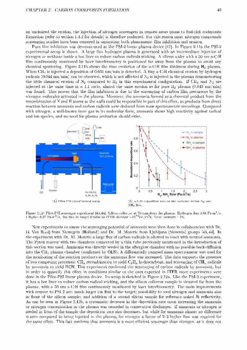
CHAPTER 2. CARBON CODEPOSITS FORMATION 49
an undesired tile erosion, the injection of nitrogen scavengers in remote areas prone to fuel-rich codepositsformation (refer to section 1.4.2 for details) is therefore preferred. For this reason most nitrogen compoundsscavenging studies have been centered in separating both phenomena: �lm inhibition and erosion.
Pure �lm inhibition was demonstrated at the PSI-2 linear plasma device [47]. In Figure 2.11a the PSI-2experimental setup is shown. A large �ux hydrogen plasma is generated with an intermediate injection ofnitrogen or methane inside a hot liner to reduce carbon radicals sticking. A silicon wafer with a 50 nm a-C:H�lm continuously monitored by laser interferometry is positioned far away from the plasma to avoid anychemical sputtering. Figure 2.11b shows the time evolution of the a-C:H �lm thickness during H2 plasma.When CH4 is injected a deposition of 0.031 nm/min is detected. A tiny a-C:H chemical erosion by hydrogenradicals (0.044 nm/min) can be observed, which is not a�ected if N2 is injected in the plasma demonstratingthe little chemical erosion of N2 compared to H2 in this experimental con�guration. If CH4 and N2 areinjected at the same time in a 1:1 ratio, almost the same erosion as for pure H2 plasma (0.043 nm/min)was found. This proves that the �lm inhibition is due to the scavenging of carbon �lm precursors by thenitrogen molecules activated in the plasma. Moreover, the ammonia formed as a chemical product from therecombination of N and H atoms at the walls could be responsible in part of this e�ect, as products from directreaction between ammonia and carbon radicals were deduced from mass spectrometric recordings. Comparedwith nitrogen, a well-known inert gas in its molecular form, ammonia shows high reactivity against radicaland ion species, and no need for plasma activation should exist.
(a) Pilot-PSI experimental setup (b) a-C:H deposition rate on the collector versus N2 and
NH3 �ow.
Figure 2.12: Pilot-PSI scavenger experiment [43,44]. Silicon collector at 70 mm from the plasma. Hydrogen �ux 3.66 Pa·m3/s,CH4�ux 0.27 Pa·m3/s. Ion �ux at target similar to ITER divertor ∼1024ion/m2s. Total pressure 4 Pa.
New experiments to assess the scavenging potential of ammonia were then done in collaboration with Dr.G. Van Rooij from Niewegein (Holland) and Dr. M. Mozetic from Ljubljana (Slovenia) groups [43, 44]. Inthe experiment with Dr. M. Mozetic a large �ux of carbon radicals is allowed to react with neutral ammonia.The Pyrex reactor with two chambers connected by a thin tube previously mentioned in the introduction ofthis section was used. Ammonia was directly seeded in the afterglow chamber with no possible back-di�usioninto the CH4 plasma chamber (con�rmed by OES). A di�erentially pumped mass spectrometer was used forthe monitoring of the reaction products as the ammonia �ow was increased. The data supports the presenceof two competing processes: CHx recombination to yield C2Hx hydrocarbons, and scavenging of CHx radicalsby ammonia to yield HCN. This experiment con�rmed the scavenging of carbon radicals by ammonia, butin order to quantify this e�ect in conditions similar to the ones expected in ITER more experiments weredone in the Pilot-PSI linear plasma device. Its setup is sketched in Figure 2.12a. Like the PSI-2 experiment,it has a hot liner to reduce carbon radical sticking, and the silicon collector sample is situated far from theplasma, with a 50 nm a-C:H �lm continuously monitored by laser interferometry. The main improvementswith respect to PSI-2 are: much larger ion �ux to the target; possibility to seed nitrogen and ammonia alsoin front of the silicon sample; and addition of a second silicon sample for reference naked Si re�ectivity.As can be seen in Figure 2.12b, a systematic decrease in the deposition rate upon increasing the ammoniaor nitrogen concentration in the plasma was recorded in consecutive discharges. If ammonia or nitrogen isseeded in front of the sample the deposition rate also decreases, but while for ammonia almost no di�erenceis seen compared to being injected in the plasma, for nitrogen a factor of 2�3 higher �ow was required forthe same e�ect. This fact con�rms that ammonia is a more e�cient scavenger than nitrogen, as it does not

CHAPTER 2. CARBON CODEPOSITS FORMATION 50
need to be activated by the plasma, and can therefore be injected in remote parts in ITER.The scavenger concept has also been tested in capacitive RF plasmas by Vassallo et al. [48, 49]. Film
deposition inhibition was observed in a �oating sample (no ion bombardment, thus almost no sputtering)if a certain threshold in the applied RF power was surpassed. This threshold was much lower for ammoniathan for nitrogen, which corroborates its better scavenging ability. By OES N· and NH· were pointed outto be the main scavenger species. If the reactor walls are initially covered with a thin a-C:H �lm a largequantity of atomic hydrogen, H·, is detected, which could also play a role in the chemical erosion of a-C:H�lms. This technique was also applied to mixed a-C:H/W �lms, as expected in ITER if carbon target tilesare installed at the strike points. A strong suppression of carbon was found showing that tungsten does notinterfere greatly.
On the other hand, the chemistry of a N2/CH4 mixture in a H2 plasma, has been extensively studied inthe fabrication of the super-hard a-CNx:H and the hypothetical β-C3N4 by PACVD [46,65,66]. Some of thoseworks show clear evidences of lower deposition rate if more nitrogen was injected. Moreover, they describeda very complex chemistry depending on many factors, some of them classical like reactants concentration,applied power, plasma generation technique, etc. Our group discovered a di�erent factor not so usuallydescribed which proved to be essential: the reactor walls, as very di�erent products from the same plasmawere obtained when the stainless steel reactor walls were covered by a thin a-C:H �lm [45]. If the scavengertechnique is applied in a nuclear fusion device, depending on the injection location, and thus plasma facingmaterials (tungsten, carbon, stainless steel, etc), the plasma chemistry could be very di�erent. In order tostudy the involved surface reactions and their relationship in the scavenger e�ect, it has to be determinedwhich are the main intermediate compounds related to each reactor wall condition and their relationshipwith the surface, specially to con�rm if a thin a-C:H �lm is necessary for the scavenger reactions to start [41].Nevertheless, reconstructing the original composition of the gas mixture, and then the intermediate species,from conventional mass spectrometry is very complex. The critical point is the sampling interface. Nofurther chemistry beyond the collimator separating the plasma region and the high vacuum side of the massspectrometer is usually desired. However, the presence of low sticking radicals in the plasma mixture can leadto some distortion in the sampled spectrum. Conversely, a systematic study of the distortion e�ect associatedto the changes in sampling conditions can provide extra information about the chemical processes taking placeinto the reactor itself. This study is addressed in the present work varying the physical distribution of thesampling tube and by means of Cryo-Trap Assisted Mass Spectroscopy (CTAMS). This technique is based onthe condensation of some compounds of the sampled gas to allow for the integration of small concentrationsand discrimination among compounds with overlapping cracking pattern [45, 46]. Finally, special attentionwill be paid to the trapping of radicals and unstable molecules.
2.2.2 Experimental
2.2.2.1 Setup
The setup used is depicted in Figure 2.13, being the same as in previous works [45,46,67]. It can be divided inthree parts: �rst, the plasma reactor in which a continuous in-situ monitoring of the �lm growth is performedthrough laser interferometry (this technique will be fully explained in section 3.1.2); second, a diagnosticchamber with a di�erentially pumped mass spectrometer; and third, the connection between both chambers(item 14 in Figure 2.13), which will be eventually modi�ed in order to test the e�ect of unstable moleculesand radical recombination on the detected signals. In the entrance of the analysis chamber a 5 mm pinhole(item 7), for a pressure reduction factor of 3 orders of magnitude, and a cold trap (item 11) are located. Thiscold trap is eventually �lled with liquid nitrogen for the partial depletion of products from the sampled gas.The plasma and the diagnostic chambers were pump down to 5·10-5 Pa and 10-7 Pa respectively by means ofseparate turbomolecular pumps in series with roughing pumps. The experiments were done with high purity(99,999%) H2/CH4/N2 gas mix with a ratio of 90:5:5 respectively, 0.8 Pa pressure and 100 mA of plasmacurrent. Notwithstanding, some experiments have also H2O as a reactant due to a high, unintentional watercontamination inside the reactor chamber as a result of an incomplete vacuum conditioning.
As previously said, di�erent con�gurations of the plasma reactor and the connection between chambershave been tested. The plasma reactor can be operated with fresh, stainless steel walls. For this purpose,a He/O2 (80/20) Direct Current Glow Discharge (DC) plasma was applied to eliminate any residual orpreviously deposited carbon layer. This plasma was followed by a pure He DC-plasma to desorb the previouslyproduced oxygen products from the walls: H2O, CO and CO2. The reactor could also be operated with fullcarbonized walls, covered by a 200 nm thick a-C:H �lm, by means of a He/CH4 (80/20) DC-plasma afterthe He plasma cleaning. On the other hand, the connection between chambers was modi�ed physically by acombination of tubes in order to achieve direct/indirect vision by means of elbows, and also variable distance(short: 10 cm; medium: 45 cm; long 80 cm) between the plasma and the cold trap. Medium and long, direct

CHAPTER 2. CARBON CODEPOSITS FORMATION 51
Figure 2.13: Experimental setup for scavenger and plasma removal experiments. 1. Pumping system (turbo pump and rotaryvacuum pump), 2. Manometer (Bayard Alpert), 3. Capacitance manometer, 4. Isolation valve, 5. Leak valve (gas inlet), 6.Anode, 7. Diaphragm (di�erential pumping), 8. Quadrupole mass spectrometer, 9. Optical port, 10. Sample Manipulator, 11.Cryogenic (LN2) trap with thermocouple, 12. Langmuir probe, 13. Electron gun, 14. sampling connection, may include elbows(see text for details).
connections are made with a bellow of a large inner surface, so the real stainless steel surface exposed to thegas molecules is very large. All these elements were eventually covered with Papy�ex © (graphite paper),to simulate carbon-coated conditions. In the case of the bellow, Papy�ex suppresses the large inner stainlesssteel area of the parts covered with it. A summary of the combinations used during the experiments is shownin Tables 2.3 and 2.4.
2.2.2.2 Experiment phases
A Stanford Research Systems SRS Residual Gas Analyzer (RGA-100) is used to measure the mass spectraof the products. The RGA is not calibrated, so absolute composition and measurement errors cannot becalculated. Notwithstanding, the repeatability of the signal is very high, with a variability of around 2-3%.The CTAMS technique was applied to study the minority products. It consists on the partial condensationof the sampled gas on a liquid nitrogen cold �nger (cold trap) during the plasma, approximately at 100 K,and the subsequent evaporation of the condensed compounds by slow heating up, around 2.5 K/min, oncethe plasma is stopped and the connection of the cold trap to the plasma chamber is cut o�. In order toavoid any perturbation to the plasma, and to improve sensitivity, the reactants must not be condensed in thecold �nger, and ideally all the products have to be trapped. As can be seen in Table 2.2 the condensationtemperature for all the reactants (H2, CH4, and N2) at the pressure used in this work is lower than the cold�nger (100 K), so they will not condense. However, as can be seen at the same table, not all the possibleproducts are going to be condensed at the cold trap, as it happens with C2Hx hydrocarbons, except C2H2
which will undergo a partial condensation if its yield is too large. Because of the CTAMS technique, threephases during the experiment can be distinguished:
1. A free plasma phase before �lling the cold trap.
2. A condensation phase when the cold trap is �lled with liquid nitrogen and part of the sampled productsgenerated in the plasma are condensed on it.The full plasma phase include phases 1 and 2.
3. An evaporation phase, when the plasma is stopped and the cold trap is emptied of liquid nitrogen andleft to heat up. Then, the previously condensed products are evaporated sequentially, and are detectedanalogously as with Thermal Desorption Spectroscopy (TDS). As the temperature in this phase is notactively controlled, the evolution of the temperature will depend on the total pressure (i.e. evaporationrate). Notwithstanding, the spontaneous temperature ramp was similar in all experiments. In order tomake evaporation peaks for the same products in di�erent experiments easier to compare, the time inthe evaporation phase has been normalized to the time of the water peak maximum. This normalizationand the similar evolution of the temperature for all the experiments allows for the temperature to onlybe shown in the �rst �gure of each reactor wall for simplicity.
2.2.2.3 Mass spectra interpretation
In this work the cracking patterns of the main products and reactants at the RGA ionizer cause an importantoverlapping on some mass to charge (m/q) ratios at the detector. Because of this overlapping the identi�cation
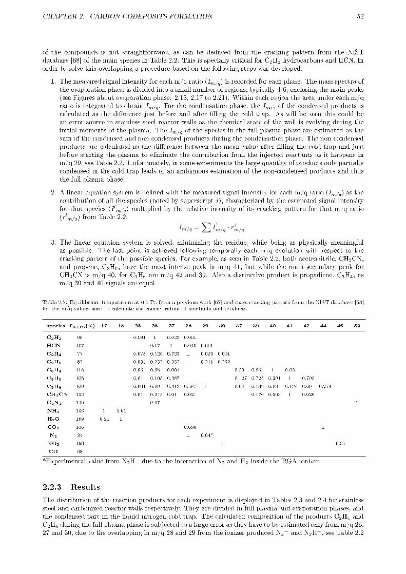
CHAPTER 2. CARBON CODEPOSITS FORMATION 52
of the compounds is not straightforward, as can be deduced from the cracking pattern from the NISTdatabase [68] of the main species in Table 2.2. This is specially critical for C2Hx hydrocarbons and HCN. Inorder to solve this overlapping a procedure based on the following steps was developed:
1. The measured signal intensity for each m/q ratio (Im/q) is recorded for each phase. The mass spectra ofthe evaporation phase is divided into a small number of regions, typically 4-6, enclosing the main peaks(see Figures about evaporation phase: 2.15, 2.17 to 2.21). Within each region the area under each m/qratio is integrated to obtain Im/q. For the condensation phase, the Im/q of the condensed products iscalculated as the di�erence just before and after �lling the cold trap. As will be seen this could bean error source in stainless steel reactor walls as the chemical state of the wall is evolving during theinitial moments of the plasma. The Im/q of the species in the full plasma phase are estimated as thesum of the condensed and non-condensed products during the condensation phase. The non-condensedproducts are calculated as the di�erence between the mean value after �lling the cold trap and justbefore starting the plasma to eliminate the contribution from the injected reactants as it happens inm/q 29, see Table 2.2. Unfortunately, in some experiments the large quantity of products only partiallycondensed in the cold trap leads to an ambiguous estimation of the non-condensed products and thusthe full plasma phase.
2. A linear equation system is de�ned with the measured signal intensity for each m/q ratio (Im/q) as thecontribution of all the species (noted by superscript i), characterized by the estimated signal intensityfor that species (Iim/q) multiplied by the relative intensity of its cracking pattern for that m/q ratio(rim/q) from Table 2.2:
Im/q =∑
Ii
m/q · rim/q
3. The linear equation system is solved, minimizing the residue, while being as physically meaningfulas possible. The last point is achieved following temporally each m/q evolution with respect to thecracking pattern of the possible species. For example, as seen in Table 2.2, both acetronitrile, CH3CN,and propene, C3H6, have the most intense peak in m/q 41, but while the main secondary peak forCH3CN is m/q 40, for C3H6 are m/q 42 and 39. Also a distinctive product is propadiene, C3H4, asm/q 39 and 40 signals are equal.
Table 2.2: Equilibrium temperature at 0.1 Pa from a previous work [67] and mass cracking pattern from the NIST database [68]for the m/q values used to calculate the concentration of reactants and products.
species T0,1Pa(K) 17 18 25 26 27 28 29 30 37 39 40 41 42 44 46 52
C2H2 90 0.191 1 0.022 0.001
HCN 137 0.17 1 0.015 0.001
C2H4 77 0.078 0.529 0.623 1 0.023 0.001
C2H6 82 0.035 0.232 0.332 1 0.215 0.262
C3H4 116 0.05 0.05 0.001 0.33 0.96 1 0.03
C3H6 105 0.01 0.105 0.387 0.127 0.725 0.291 1 0.703
C3H8 106 0.001 0.09 0.419 0.587 1 0.04 0.189 0.03 0.134 0.06 0.274
CH3CN 153 0.01 0.015 0.01 0.021 0.176 0.503 1 0.026
C2N2 120 0.07 1
NH3 136 1 0.01
H2O 199 0.21 1
CO2 106 0.098 1
N2 34 1 0.04*
NO2 190 1 0.37
CO 68 1
*Experimental value from N2H+ due to the interaction of N2 and H2 inside the RGA ionizer.
2.2.3 Results
The distribution of the reaction products for each experiment is displayed in Tables 2.3 and 2.4 for stainlesssteel and carbonized reactor walls respectively. They are divided in full plasma and evaporation phases, andthe condensed part in the liquid nitrogen cold trap. The calculated composition of the products C2H4 andC2H6 during the full plasma phase is subjected to a large error as they have to be estimated only from m/q 26,27 and 30, due to the overlapping in m/q 28 and 29 from the ionizer produced N2
+ and N2H+, see Table 2.2
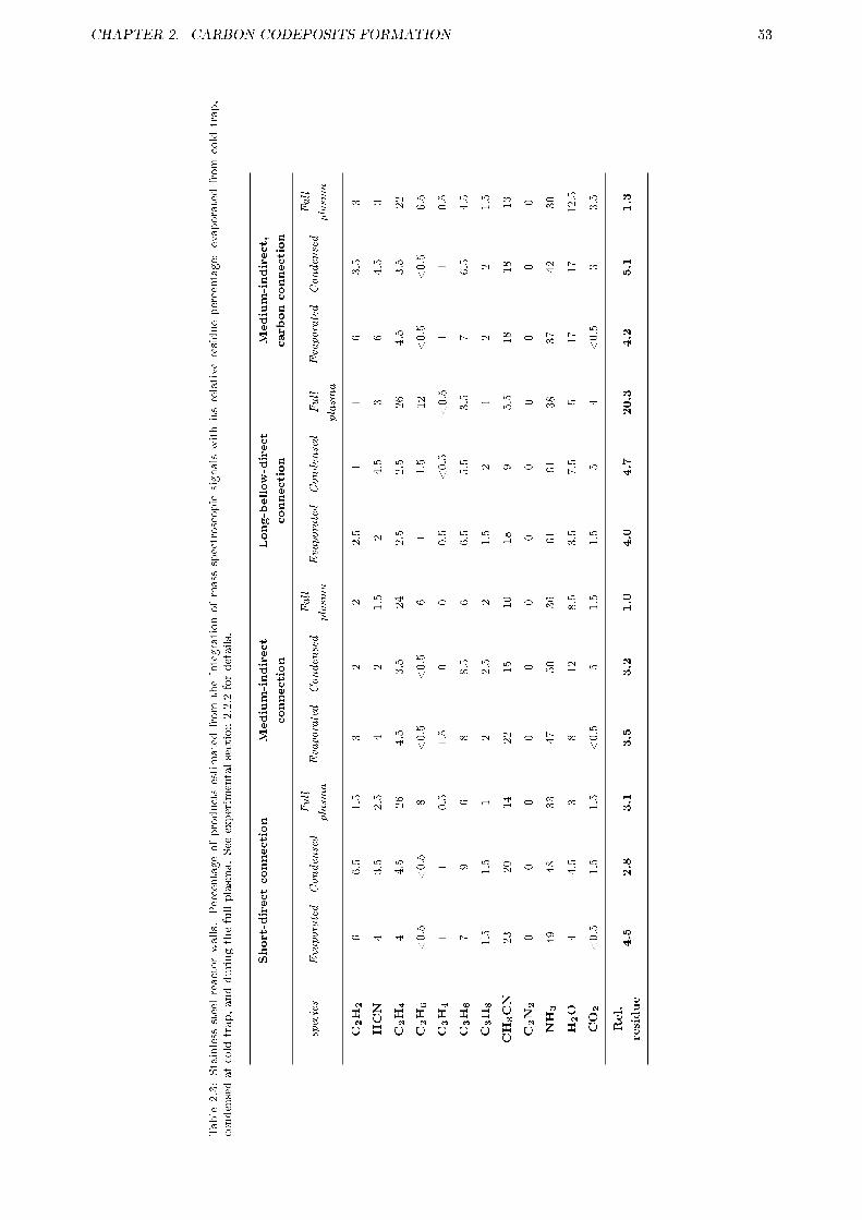
CHAPTER 2. CARBON CODEPOSITS FORMATION 53
Table
2.3:Stainless
steelreactorwalls.
Percentageofproductsestimatedfrom
theintegrationofmass
spectroscopic
signalswithitsrelativeresiduepercentage:
evaporatedfrom
cold
trap,
condensedatcold
trap,andduringthefullplasm
a.See
experimentalsection2.2.2fordetails.
Short-directconnection
Medium-indirect
connection
Long-bellow-direct
connection
Medium-indirect,
carbonconnection
species
Evaporated
Condensed
Full
plasm
aEvaporated
Condensed
Full
plasm
aEvaporated
Condensed
Full
plasm
a
Evaporated
Condensed
Full
plasm
a
C2H2
66.5
1.5
32
22.5
11
63.5
3
HCN
43.5
2.5
42
1.5
24.5
36
4.5
3
C2H4
44.5
26
4.5
3.5
24
2.5
2.5
26
4.5
3.5
22
C2H6
<0.5
<0.5
8<0.5
<0.5
61
1.5
12
<0.5
<0.5
6.5
C3H4
11
0.5
1.5
00
0.5
<0.5
<0.5
11
0.5
C3H6
79
68
8.5
66.5
5.5
3.5
76.5
4.5
C3H8
1.5
1.5
12
2.5
21.5
21
22
1.5
CH3CN
23
20
14
22
15
10
18
95.5
18
18
13
C2N2
00
00
00
00
00
00
NH3
49
48
33
47
50
36
61
61
38
37
42
30
H2O
44.5
38
12
8.5
3.5
7.5
517
17
12.5
CO2
<0.5
1.5
1.5
<0.5
51.5
1.5
54
<0.5
33.5
Rel.
residue
4.5
2.8
3.1
3.5
3.2
1.0
4.0
4.7
20.3
4.2
5.1
1.3

CHAPTER 2. CARBON CODEPOSITS FORMATION 54
Table2.4:Carbonized
reactorwalls.Percentageofproductsestimatedfromtheintegrationofmassspectroscopicsignalswithitsrelativeresiduepercentage:
evaporatedfromcoldtrap,condensed
atcold
trap,andduringthefullplasm
a.See
experimentalsection2.2.2fordetails.
Short-directconnection
(humid)
Short-directconnection
(dry)
Medium-indirect
connection(humid)
Medium-indirect
connection(dry)
species
Evaporated
Condensed
Evaporated
Condensed
Evaporated
Condensed
Full
plasm
aEvaporated
Condensed
C2H2
3535
3736
2130
2635
35HCN
3638
4745
3.5
5.5
545
45C2H4
3.5
2.5
45.5
3.5
312
54
C2H6
10.5
<0.5
<0.5
11
41.5
1.5
C3H4
1.5
11
12.5
2.5
21.5
1.5
C3H6
0.5
<0.5
<0.5
<0.5
32
1.5
0.5
0.5
C3H8
00
<0.5
<0.5
0.5
0.5
0.5
0.5
0.5
CH3CN
3.5
2.5
11.5
139.5
81..5
2C2N2
0.5
10.5
10
00
11
NH3
107.5
45
2528
243.5
0H2O
712
3.5
4.5
2515
135
8.5
CO2
00
00
1.5
3.5
50
0
Rel.
residue
1.5
1.3
1.5
2.6
3.3
2.5
1.3
1.4
0.1

CHAPTER 2. CARBON CODEPOSITS FORMATION 55
Table2.4(C
ont.)
Medium-indirect,
carbonconnection
Medium-bellow-direct,
carbonconnection
Long-bellow-direct,
carbon/metalconnection
Long-bellow-direct
connection
species
Evaporated
Condensed
Evaporated
Condensed
Evaporated
Condensed
Evaporated
Condensed
C2H2
3535
3235
3435
3336
HCN
4848
4844
4747
4946
C2H4
4.5
3.5
43
43
43.5
C2H6
<0.5
<0.5
0.5
0.5
0.5
0.5
0.5
0.5
C3H4
11.5
11.5
11
11.5
C3H6
<0.5
<0.5
0.5
0.5
<0.5
<0.5
<0.5
<0.5
C3H8
<0.5
<0.5
00
<0.5
<0.5
<0.5
<0.5
CH3CN
1.5
1.5
1.5
1.5
1.5
21.5
2C2N2
11
11
11
10.5
NH3
4.5
3.5
55
50
51.5
H2O
4.5
4.5
78
69.5
4.5
8CO2
00
00
00
00
Rel.
residue
1.4
0.3
1.1
0.6
1.3
0.8
1.3
0.5

CHAPTER 2. CARBON CODEPOSITS FORMATION 56
for their cracking pattern. On Table 2.3 it can be seen that for experiments with stainless steel reactor wallsthis is usually not an issue except in the long-bellow-direct connection case. Conversely, for experiments oncarbonized reactor walls this overlapping together with the incomplete condensation of acetylene results in alarge uncertainty in the estimation of non-condensed, and thus full plasma, products. The estimated values forfull plasma are therefore omitted in Table 2.4 with the exception of humid medium-indirect connection becauseof their relevance and its complete acetylene condensation. The e�ects on the plasma chemistry are classi�edin reactor walls e�ects, subsection 2.2.3.1, the e�ects due to sampling arrangement, subsection 2.2.3.2, andthe e�ects because of unintentional oxygen contamination, subsection 2.2.3.3.
2.2.3.1 E�ect of reactor walls
The main products from the plasma of this work have been studied and identi�ed in previous works bythis group [45, 46, 67, 69]. Here, a more detailed semi-quantitative analysis has been done. In Table 2.3 itcan be seen that on stainless steel reactor walls the main products during the full plasma phase are NH3
�predominant�, C2H4 and CH3CN. As minor products, C2H6, C3H6, C2H2 and HCN are obtained. Forcarbonized reactor walls, Table 2.4, the main products obtained from the condensation on the cold trapare C2H2 and HCN with C2H4 and NH3 as the most important minor products. The estimation of theuncondensed species, and thus full plasma phase, is not reliable in this case, but seems to point to a 10-15%more of uncondensed C2H2, with a smaller contribution of C2H4 (8-14%) and C2H6 (2-8%) to the total. Abetter characterization of this particular conditions can be found in a previous work [69].
Reactor wall e�ects are very evident as can be deduced from the di�erences between the recorded massspectra of the plasma and evaporation phases: in stainless steel reactor walls, Figures 2.14 for plasma and2.15 for evaporation; and in carbonized reactor walls, Figures 2.16 for plasma and 2.17 for evaporation. In�gures of the recorded spectra during the plasma, 2.14 and 2.16, m/q values of 28 and 29 are not displayedbecause the strong overlapping with N2
+ and N2H+.During the full plasma phase on experiments on stainless steel reactor walls a clear time evolution in
the production of the species at m/q 17, 18, 26, 27, and 44 can be observed, complementary to an initialdelay in the growth of m/q 39, 40, 41, and mainly 42, see Figure 2.14, and specially its inset. These m/qevolutions can be ascribed to products by means of their mass cracking pattern, Table 2.2. In this way, it canbe deduced the decrease of H2O and NH3, that CO2 disappears in a few minutes, together to an increase ofC2H4, CH3CN, C3H4 and C3H6, the last three increasingly more delayed. C2H2, C2H6 and HCN productionseem to be constant as m/q 30 and the ratios of m/q 26/27 and 26/25 do not change, see Table 2.2 fortheir cracking pattern. Some distinctive features can be identi�ed in the evaporation phase, as shown inFigure 2.15: a CH3CN peak before the water evaporation in region 4, a broad, multi-peak NH3 along regions2 to 4, and a number of smaller peaks related to a mix of NH3 and C2,3Hx at regions 1 and 2.
If reactor walls are carbonized in the full plasma phase, shown in Figure 2.16, almost no product evolutionis detected along the discharge, only a quick rise when the plasma starts in m/q 26 and 27 related to both C2H2
and HCN production. Opposed to stainless steel reactor walls, during the evaporation phase for carbonizedreactor walls fewer and larger peaks are obtained, as seen in Figure 2.17: �rst a large, pure C2H2 peak inregion 1, followed by a secondary, smaller C2H2 one together with C2H4 and C3H4 in region 2 (this peak ismore evident in other sampling con�gurations, see next section); and a large HCN peak, region 3, followedby one or two secondary HCN peaks mixed with NH3, and CH3CN or C2H4 in region 4. Only one secondaryHCN peak appears in Figure 2.17 due to the sampling con�guration, the one related to C2H4, as will beexplained in the next subsection.
On the other hand, reactants show a common behavior and dissociation degree that is only dependent onthe reactor wall. As their signals are at least one order or magnitude larger than those of the products, theyhave been omitted in Figures 2.14 and 2.16 for the sake of clarity. Their time evolution is concomitant to thatof the products, except for CH4, which is the opposite, i.e., the more CH4 is destroyed, the more productsare created. In experiments on stainless steel walls, H2 (m/q 2) increases slightly during the plasma (about5-9%,) due to the decomposition of CH4 (m/q 16), which decreases about a 12-16%. However, N2 cannotbe fully addressed as its m/q 28, which has a small increment (7-9%), overlaps with the large quantity ofgenerated hydrocarbons, C2H4 and C2H6 (see full plasma in Table 2.2). In experiments on carbonized walls,H2 (m/q 2) increases more strongly during the plasma (about 17-21%) because of a larger CH4 decomposition(m/q 16), decreasing about a 20-25%. Due to the reduced C2H4 and C2H6 production previously commented,m/q 28 only increases about a 2-3%, indicating a very low N2 decomposition.
2.2.3.2 E�ect of sampling arrangement
In order to study the reactions of plasma-borne radicals in the afterglow, which could a�ect the �nal productsobtained, di�erent connection con�gurations and inner coating between the plasma reactor and the liquid

CHAPTER 2. CARBON CODEPOSITS FORMATION 57
Figure
2.14:Plasm
aonstainlesssteelreactorwalls,withamedium
length,indirectsampling
tube.
Figure
2.15:Evaporationonstainless
steelreactorwalls,withamedium,indirectsampling
tube.
Regionsat0;0.14;0.38;0.61;1.1times.
Figure
2.16:Plasm
aoncarbonized
reactorwalls(dry),withamedium,indirectsampling
tube.
Figure2.17:Evaporationoncarbonized
reactorwalls(dry),withamedium,indirectsampling
tube.
Regionsat0;0.16;0.47;0.67;1.1times.
Massspectraof
productsduring
plasmaor
evaporated
from
liquidnitrogen
trap
afterit.In
plasma�gures
point1istheplasmastart-up,2istheactivation
ofliquid
nitrogen
trap
and3istheplasmashutdown.
Inevaporated
products
the�gures
have
been
dividedin
regionswiththeirrespective
mainproducts
percentagesgivenat
theside.Insetshave
been
addedforclarity.
Tim
ehasbeen
norm
alized
tothewater
evaporationpeak
(see
experimentalsection2.2.2).

CHAPTER 2. CARBON CODEPOSITS FORMATION 58
Figure
2.18:Evaporationonstainless
steelreactorwalls,withalong,directsamplingtube.
Regionsat0;0.12;0.19;0.36;0.46;0.69;1.1times.
Figure
2.19:Evaporationonstainless
steelreactorwalls,withashort,directsamplingtube.
Regionsat0;0.24;0.52;0.63;1.1times.
Figure
2.20:Evaporationoncarbonized
reactorwalls(dry),withashort,directsampling
tube.
Regionsat0;0.22;0.45;0.66;1.1times.
Figure
2.21:Evaporationoncarbonized
reactorwalls(humid),withamedium,indirectsam-
plingtube.
Regions(at0;0.27;0.41;0.90;1.1times).
Massspectraof
productsevaporated
from
theliquidnitrogen
trap
aftertheplasma.
Figures
have
been
dividedin
regionswiththeirrespective
mainproductspercentages
givenat
theside.Insetshave
been
addedforclarity.
Tim
ehasbeen
norm
alized
tothewater
evaporationpeak
(see
experimentalsection2.2.2).

CHAPTER 2. CARBON CODEPOSITS FORMATION 59
nitrogen cold trap have been tested. In experiments in stainless steel reactor walls, to change a short-directconnection for a medium-indirect one has little e�ect in the total quantity of products obtained (see thedi�erent phases in Table 2.3). Conversely, when a long-bellow-direct connection is used more NH3 is detectedin the evaporated products in detriment of C2Hx, HCN and CH3CN (condensed and full plasma estimationsare not completely reliable, and they are therefore not compared). However, during the products evaporationthe di�erences are more patent, as can be seen in their respective mass spectra. This di�erence is evidentin the long-bellow-direct connection, region 3 in Figure 2.18, where the NH3 peak is narrower and it doesnot have a multi-peaked structure as when medium-indirect connection, regions 2-3 in Figure 2.15, andshort-direct connection (Figure 2.19) are used. In the case of the minor C2,3Hx peaks at the beginning ofthe evaporation, while for a medium-indirect connection they are broad and of similar size, regions 1-3 inFigure 2.15 and its inset, they are narrower for the long-bellow-direct connection, regions 1-4 in Figure 2.18and its inset. Meanwhile, in the short-direct connection, the C2,3Hx peak at ∼0.3 water normalized time(region 2 in Figure 2.19) is much bigger than the others (about 10-20 times), and is almost the only onepresent.
For experiments in carbonized reactor walls (Table 2.4), no signi�cant di�erences are detected on theevaporated and condensed products distribution for dry experiments. Notwithstanding, some di�erences areobvious in the mass spectra of the evaporated products depending on the connection con�guration. Forexample, if the spectra of medium-indirect connection is compared to any other with direct connection, itcan be seen that the secondary C2H2 peak in region 2, associated with C2H4 and C3H4 (follow in inset ofFigure 2.20 the evolution of m/q 28 for C2H4 and m/q 39 and 40 for C3H4), is strongly reduced: compare thepeak in Figure 2.20 with Figure 2.17; and also the HCN secondary peak associated with CH3CN in region 4disappears (compare the peaks in insets of Figure 2.17 and 2.20).
Finally the use of papy�ex to simulate carbon coating of the sampling tube showed no e�ect on theproducts recovered in carbonized walls, see all phases at Table 2.4, but in stainless steel it seems to have asmall e�ect. Comparing to the non-carbon connection, see Table 2.3, the mayor products NH3 and CH3CNslightly decrease and increase respectively in the full plasma phase, while at the evaporated phase both arelower. In all phases, some minor products increase, C2H2 and HCN, while C3H6 decreases. However, largewater levels are recovered in the evaporation during the experiment covered with papy�ex, which points toa di�erent e�ect other than papy�ex as will be seen in the following section.
2.2.3.3 E�ect of oxygen contamination
Two main sources of oxygen contamination have been found in the experiments. These sources are common tomost vacuum plasma thin �lm processes, especially whenever chemical reactions are involved, like in PACVD,but they can play a crucial role in the plasma chemistry, as will be shown.
As commented previously, the �rst source of oxygen contamination comes from the conspicuous oxidelayer present in stainless steel reactor walls. There is evidence of CO2 condensation in the cold trap fromits posterior evaporation, signal m/q 44, at the �rst peak of the mass spectra in Figures 2.15, 2.18 and 2.19and their insets. Furthermore, as it can be inferred from the Figure 2.14 and its inset, the drop of bothm/q 18 and 44 peaks, specially the last one, corresponding to H2O and CO2 respectively, is concomitantto the growth of many others species commented previously in section 2.2.3.1 (the initial delay in m/q 39,40, 41, and mainly 42, related to C2H4, CH3CN, C3H4 and C3H6). The role of the oxygen in the plasmachemistry is therefore very evident, although it is not clear whether this role is due to either a surface or agas phase-driven process.
The second source comes from the residual water present in any vacuum system. In Table 2.4 its pro-gressive e�ects on the evaporated and condensed products distribution in carbonized reactor walls can bedetermined from the experiments with high, unintentional H2O contamination (7.1 and 25.8% recovered atthe evaporated phase) and water-free (dry) ones (3-5% recovered at the evaporated phase). The presence oflarge concentrations of water completely changes the plasma chemistry, as the products obtained are evensimilar to the ones detected when the same experiments were done on stainless steel reactor walls: com-pare products distribution of humid experiments in Table 2.4, specially at 25.8% evaporated water, withany experiment in Table 2.3. Larger quantities of NH3, CH3CN and some C3H6 are produced, while C2H2
production is greatly reduced and HCN is almost suppressed at large water levels. The mass spectra of theproducts evaporated from the liquid nitrogen trap, Figure 2.21, dramatically change with respect to the dryexperiment, Figure 2.17. Figure 2.21 shows a clear combination of carbonized reactor walls: �rst C2H2 peakin region 1; and stainless steel reactor walls: NH3 multipeaks along regions 2-3, and CH3CN peak in region3 before the water release. As can be expected some CO2, at m/q 44, is detected in region 1. This plasmachemistry modi�cation seems to be speci�c to carbonized reactor walls, as in stainless steel walls no such largee�ect is observed. In fact, it seems that carbonized walls plasma chemistry moves to stainless steel walls one.Nonetheless, as seen in the previous subsection, when the inner wall of the connection tube was covered with

CHAPTER 2. CARBON CODEPOSITS FORMATION 60
papy�ex, small di�erences in the product distribution are found together with a large level of water duringevaporation. As seen in the Figure 2.22 the initial level of water (m/q 18) in papy�ex-covered connection issimilar to the initial level of uncovered one, Figure 2.15. But while in the uncovered experiments the waterlevel quickly decreases during plasma, in the papy�ex-covered one it decreases very slowly. Furthermore,as can be seen in the inset of the Figure 2.22 the delays of the m/q 39, 40, 41 and specially 42 are muchmore evident than in the uncovered one. All this probably means that the stainless steel walls were moreoxidized, and therefore the di�erences in most of the products (NH3, CH3CN, C3H6) can be explained bythese increased delays in their production. However, this would not be the case for C2H2 and HCN, whichwould be more related to the use of papy�ex covering.
Figure 2.22: Mass spectra of products during the plasma on stainless steel reactor walls, with a medium length, indirect samplingtube covered with papy�ex to simulate carbon coating. Point 1 is the plasma start-up, 2 is the activation of liquid nitrogen trapand 3 is the plasma shutdown.
There are other oxygen sources in a vacuum system, like water and oxygen from the gas fed lines and thecompressed gas bottles. These sources were not considered because of two reasons. First, the gas fed lineswere purged before the experiment until the m/q 32 (oxygen from air) reached a plateau with an intensityclose to the minimum detection point. Second, from these sources the injected oxygen and water quantitieswould be constant or slowly decreasing, and should not present a fast time evolution in the plasma as theyactually does.
2.2.4 Discussion
Precursors responsible for a-C:H deposition in methane inductively coupled plasmas were determined by otherauthors [34] based in the mean dissipated energy per source gas molecule. The main precursors from lowerto higher mean dissipated energy are: CH, C2H3 + C2H and carbonaceous ions. However, for the plasmageneration of this work (direct current) the ions contribute in 1/3 to the �lm growth, and the ion bombardingenergy ranges up to full discharge voltage (260 V), so chemical sputtering by hydrogen and nitrogen has alsoto play a role [32]. As commented in the motivation, the a-C:H �lm inhibition was seen in samples far fromthe plasma even when N2 or NH3 were added just in front of the sample [47]. This means that N2, andspecially NH3, do not need to be activated in the plasma to scavenge the radical carbonaceous precursors, sotheir possible inhibition paths are wide.
In order to study the surface e�ects involved, �rst the main species related to each reactor wall conditionand their relationship with the �lm precursors for scavenger e�ect has to be determined, subsection 2.2.4.1.Then the plasma-borne radicals and their stability will be discussed in subsection 2.2.4.2. To �nish, insubsection 2.2.4.3 the oxygen contamination e�ects on the main produced species will be used for a betteridenti�cation of the reaction paths of carbon �lms formation.
2.2.4.1 Reactor wall e�ects
Reactants and intermediates
The dissociation of the reactants H2 and CH4 when the plasma starts shows a strong dependence with thereactor walls. More CH4 is destroyed in carbonized walls than in stainless steel ones (20-25% to 12-16% in

CHAPTER 2. CARBON CODEPOSITS FORMATION 61
m/q 16 decrease), which leads to larger hydrocarbons production, and particularly more unsaturated ones(compare evaporated and condensed C2H2, C3H4 at Tables 2.3 and 2.4). Accordingly, both reaction pathstoward unsaturated hydrocarbons lead also to larger H2 production when the reactor walls are carbonized(17-21% to 5-9% in m/q 2 increase). Conversely, N2 decomposition has no clear changes as the di�erencesin m/q 28 for stainless steel and carbonized reactor walls, (7-9% and 2-3% increase respectively) could beascribed to the di�erent production of C2H4 and C2H6 during the full plasma phase, because their masscracking patterns have a strong signal in m/q 28, see Table 2.2. The total N-bearing products (HCN,CH3CN, C2N2 and NH3) produced during the full plasma phase in stainless steel reactor walls are closeto 50%, see Table 2.3. Unfortunately, the unreliable estimation of the product distribution during the fullplasma phase for carbonized reactor walls makes di�cult any comparison. Nonetheless, the only N-bearingproduct produced in large amounts is HCN, around 45-50% in the evaporated phase. Taking into accountthe relatively low quantity of non-condensed products, a 35-40% of N-bearing molecules in the full plasmaphase can be estimated. This con�rms the lower reactivity of N2 in carbonized walls than in stainless steelones, mainly due to the large NH3 formation in the last.
It is known that the intermediate products chemistry in a plasma plays the main role in the �nal productsdistribution. In a DC-plasma relatively large ion and low radical production are expected, so only radicalswith a low surface loss probability could be found in appreciable quantities in the plasma. The surface lossprobability and sticking coe�cient in a-C:H and stainless steel for the main radical species of this work can befound in Table 2.5. For ions the surface loss probability (and usually sticking coe�cient) is 1. Four di�erentreactor conditions have been de�ned: stainless steel reactor walls, at steady state and at with the initialoxides, and carbon-coated reactor walls with and without water contamination. Conditions related to oxygene�ects will be studied in section 2.2.4.3.
Steady state reactions on stainless steel reactor walls have been previously analyzed [69]. The mostimportant ionic species found were protonated intermediates like H3
+, N2H+, NH4+ and CH5
+, but alsoother intermediates like C2H5
+ and C2H4N+. Considering the �nal products obtained, as predominantradical species we can expect H·, CH2·, CH3·, C2H5· and NH·, as their surface loss probability is relativelylow, see Table 2.5. N· is not expected as most of it will be converted e�ciently into NHx on the stainlesssteel reactor walls [70, 71]. At the initial moments of the plasma, when the reactor walls are oxidized, NOand highly-reactive radicals like O· could be present, which could a�ect greatly other products, since NO is awell-known radical scavenger. The concentration of CH3· in the plasma is complex to estimate as its stickingcould be as low as to 10-6 on hot stainless steel (as it is heated by ion bombardment during the experiment),but could increase up to four orders of magnitude on cold stainless steel (like at the connection tubes) or ifthe thin carbon �lm produced spontaneously at the reactor walls has an e�ect on it [41], Table 2.5.
In carbon reactor walls similar ionic intermediate species could be expected, mostly protonated due to thelarge CH4 dissociation, and thus H2 production: H3
+, N2H+, CH5+, C2H3
+ and H2CN+. However, radicalscould be a bit di�erent, once considered the �nal products obtained and the requirement of low surface lossprobability: H·, CH2·, CH3·, C2H5· and N·. If water contamination is important, some NO, H2O+, H3O+,OH·, NH4
+ and NH· will be present. They will have a large impact on the plasma chemistry as will be seenin subsection 2.2.4.3.
Products
Using a cold trap to condense a mix of compounds has some drawbacks. First of all, some compounds canreact in the developed ice, although the low temperature will limit the kinetic and thus its e�ects in the�nal results. Some unstable compounds can also be trapped at low temperatures, like radicals or othercompounds, and decompose when the cold trap is heated up. This radical trapping will be explained innext subsection 2.2.4.2. Finally, there could be a group of physical e�ects related to liquid or ice whichcould di�cult the compounds identi�cation, like the solution of one compounds in the liquid of another,absorption on the ice, formation of azeotropes, etc. All these e�ects contribute to the experimental errorwhen comparing the estimated condensed to evaporated products in Tables 2.3 and 2.4. Furthermore, inexperiments in stainless steel reactor walls the evolution of the wall itself also plays an important role.Initially the stainless steel reactor walls are oxidized, but after a few minutes the surface oxygen is removedand they become fully covered with a thin a-C:H layer [41]. In carbonized reactor walls a similar e�ectis detected at large water contamination (compare medium-indirect connections at Table 2.4). Althoughreactions in the liquid and ice at the cold �nger due to the large reactivity of oxygen-related radicals, and thetrapping of a large quantity of carbon radicals produced by them could be very important. Now the mainproduction routes for each product based on the reactor wall will be addressed:
NH3: in stainless steel reactor walls, NHx (x<3) radicals react e�ciently on the surface with adsorbedhydrogen or viceversa to produce ammonia or higher hydrogen ammonia radicals, reaction 2.14.

CHAPTER 2. CARBON CODEPOSITS FORMATION 62
Table 2.5: Sticking, surface loss and recombination coe�cients for the most important radicals in a H2/CH4/N2 plasma
RadicalSticking (s); surface loss (B);
recombination (γ)Wall Refs. Comments
CH3·
s = 3.3Ö10-2 Stainless steel [72] T = 300 K
B = s = 10-2 to 10-4 a-C:H [30] Ion or H· bombardment
B = 1.3·10-3/5·10-3/10-2; s = 10-5 to
10-6.Stainless steel [73] T = 300/340-380 /420 K
B = 4·10-4; s = 1·10-4 soft a-C:H [73] T = 300 K
CH2· s = 0.025 a-C:H [34,74]
CH· B = s = 0.99 a-C:H [34,75]
C· s = 1 a-C:H [34]
C2H·B = 0.9; s = 0.8 hard a-C:H [76]
B = s = 0.8 soft a-C:H [76]
C2H3· B = 0.35; s = 0.25 soft a-C:H [76]
C2H5·B = 0.001 soft a-C:H [34]
B = 0.03 to 0.003 a-C:H [77]T= 573 K. Ion
bombardment
CN· B = 0.85; B = 0.98 at +200 V a-CNx:H [75] T = 300K
N· B = 0.07; γ = 4.8/6.3/7.5·10-3 Stainless steel [77�79] T = 330K
NH· B = 0.13; also at +200 V a-CNx:H [71,75] T=300K
NH2·B = 0.60-0.37; also at +200 V a-CNx:H [75,80] NH3/CH4 30-50%
B = 0.20; B = 0.30 at +200 V a-CNx:H [75,80] NH3/CH4 75%
O·B = 0.17 Stainless steel [78] T=330K
s = 0.1 a-C:H [16]
H·s = 0.01 a-C:H [81,82]
γ = 0.03 Stainless steel [83] T = 321 K
H· N· NH· NH2· s = 1 on free site Stainless steel [70]
H + H(s) � H2 γ = 1.5·10-3 Stainless steel [70]
N + N(s) � N2 γ = 6·10-3 Stainless steel [70]
NH + H(s) �
NH2(s)γ = 1·10-2 Stainless steel [70]
H + NH2(s) � NH3 γ = 8·10-3 Stainless steel [70]
NH2 + H(s) � NH3 γ = 1·10-2 Stainless steel [70]
H2 + NH(s) �NH3 γ = 8·10-4 Stainless steel [70]
NHx +H·→ NH3 or NHx+1 (2.14)
Variable x ranges from 0 to 2. One of the radicals has to be adsorbed at the wall, and the produced radicalcan be desorbed later, mainly as NH2 [70, 71]. This reaction justi�es the large NH3 obtained in plasmas instainless steel reactor walls and predict a large concentration of NH· and NH2· radicals in the plasma.
NH3 is also detected in small quantities in carbonized reactor walls as it seems that H radicals associatespreferentially with nitrogen in a-C:N:H �lms [84], making terminating amino groups � NH2 and thus inducingsome NH3 production. However, the production of NH3 by reaction 2.14 is also possible in the connectiontube or at the cold �nger itself, as N· and H· radicals are abundant in the plasma at carbonized reactorwalls. Due to their low surface loss probability they can survive long enough to react on these stainless steelsurfaces, see Table 2.5.
CH3CN: its ion has been detected previously in plasmas on stainless steel reactor walls [69], and as aproduct from the reaction of NH· radicals with C2 hydrocarbons [84,85], reaction 2.15.
C2Hn +NHx → CH3CN +Hn+x−3 (2.15)
The most probable precursors are C2H5· and C2H4 as the production of both CH3CN and C2H4 rises con-tinuously at the start of the plasma as commented previously. The large concentration of CH3CN obtainedon stainless steel walls is completely related to the large produced quantity of its precursors: C2H4 and NH3,and thus its radicals, see full plasma in Table 2.3.
In carbonized reactor walls other reaction paths for CH3CN are possible due to the absence of largequantities of NHx radicals. Terminating CN groups at the a-C:H surface are expected due to N· [86]. So

CHAPTER 2. CARBON CODEPOSITS FORMATION 63
some acetonitrile will be produced by abstraction with CH3· [41]. On the other hand, because of the largesticking of CN· (close to 1, see Table 2.5), gas reaction with CH4 will not be important [87]. Nonetheless,the large quantity of N· radicals present in the carbonized reactor walls plasma will react quickly with anyproduced CH3CN to N2, HCN and other hydrocarbons [88], reaction 2.16. Few acetonitrile is consequentlydetected in carbonized reactor walls, and it is only associated to a peak which probably comes from thedecomposition of trapped radicals on the ice matrix, see next section 2.2.4.2.
CH3CN +N ·→ N2 +HCN + other products (2.16)
HCN: it has a large production in dry experiments in carbonized walls. In this environment it isproduced mainly by nitrogen chemical sputtering (refer to section 1.2.2 for full explanation) of a-C:H layersat the reactor walls as it has been detected during DC-GD plasma removal of a-C:H �lms with He/N2 andH2/N2 [46,89]. Other well known reaction path is the reaction of nitrogen radicals with hydrocarbons on thegas phase [86,88], reactions 2.17 and 2.18.
N ·+CHx → HCN + (x− 1)H (2.17)
N ·+Cn≥2Hx → HCN + yH + Cn−1Hx−y−1 (2.18)
On stainless steel reactor walls experiments just a small amount of HCN is produced. Small directproduction can be expected due to the conversion of N· radical into NHx by reaction 2.14. HCN has beendetected in the highly inter-dependent peaks in regions 1-3 of Figure 2.18, but also independently from othercompounds as in the independent m/q 27 peak in region 5. This independent peak probably comes from thedecomposition along the connection tube of a very unstable radical (like HCN-NH3) allowing its separaterecovery from the other inter-dependent peaks.
C2H2: it is the main product in carbonized walls due to the e�cient production by hydrogen chemicalsputtering of the a-C:H at reactor walls [31]. This reaction path is con�rmed as no C2H2 is detected ina He/N2 plasma during the DC-GD plasma removal of a-C:H, whereas in a H2/N2 plasma it has a largeproduction [46,89].
Although a small amount of C2H2 is recovered during the evaporation of the cold trap on plasma instainless steel reactor walls, it seems feasible to be produced by the decomposition of trapped radicals on thecold trap itself, as it is only detected in the initial inter-dependent peaks, see next section 2.2.4.2 for details.
C2H4: a large quantity is obtained in experiments in stainless steel reactor walls once the oxygen orig-inated from the walls has stopped. Its origin is probably on the scavenging of C2H5
+ by ammonia [90],reaction 2.19, and the hydrogen abstraction of C2H5· radicals, most probably at the walls due to the lowradical concentration in the gas of DC plasmas, reaction 2.20:
C2H+5 +NH3 → NH+
4 + C2H4 (2.19)
C2H5 ·+H · /NHx → H2/NHx+1 + C2H4 (2.20)
Both precursors are present in large quantities in stainless steel walls due to their large stability, whichjusti�es the amount of C2H4 detected in the full plasma phase. On the other hand, it should not be condensedin the liquid nitrogen trap, see Table 2.2, but it is detected during evaporation, around 6% in the region 4of Figure 2.15 and 2.19, and region 6 of Figure 2.18 (follow m/q 28 evolution). This C2H4 is most probablyproduced during the decomposition of trapped radicals, see next section 2.2.4.2, or from adsorption on theCH3CN ice as it evaporates at the same time in spite of their very di�erent evaporation point (77 to 153 K).
As previously commented, on carbonized reactor walls the C2H4 production in the plasma cannot beexactly quanti�ed because of the incomplete C2H2 condensation, but a lower quantity than on stainlesssteel reactor walls is estimated, as it can be inferred from the fact that the m/q 27 signal (directly relatedto C2H4, as m/28 overlaps with N2) during the condensation phase is more than double on stainless steelthan on carbonized reactor walls, compare Figures 2.14 and 2.16. C2H4 can be produced on carbonizedwalls by reaction 2.20, and also from hydrogen chemical sputtering at the ion bombardment energy in thiswork [46, 91]. Although both sources would originate a large production of C2H4, they compete with itse�cient destruction by nitrogen radicals [86,88], reaction 2.18, very abundant in carbonized walls.
C2H6: it is generated from two main sources: by chemical sputtering of a-C:H [31], and by di-ethylreaction [33], reaction 2.21:
2CH3· → C2H6 (2.21)
Both C2H6 sources would compete with its partial destruction by NH· on stainless steel walls to produceCH3CN, reaction 2.15. A lower quantity is detected in carbonized walls due to the more e�cient removal ofboth C2H6 and CH3· by N·, reactions 2.18 and 2.17 respectively. If the plasma has a direct vision over thecold �nger on stainless steel reactor walls the production of C2H6 seems to be larger, compare full plasma at

CHAPTER 2. CARBON CODEPOSITS FORMATION 64
Table 2.3. This points out to the di-ethyl reaction along the connection tube and cold �nger to be the majorsource of C2H6 in both walls because of the much lower surface loss probability of CH3· than NH· and N·on cold stainless steel, see Table 2.5. Furthermore, as NH· surface loss probability is larger than N·, it alsojusti�es that more C2H6 is detected on experiments on stainless steel walls as it is destroyed less along theconnection tubes.
C3H 4,6,8 : they are minor products in both types of reactor walls. All of them are produced fromchemical sputtering of a-C:H �lm [31], competing with the destruction by NH· and N·, reactions 2.15 and2.18 respectively. Some of them could also be produced from a radical decomposition, see next section. Forexample, around a total of 6% of C3H4 is found in carbonized reactor walls, mostly in the secondary C2H2
peak at region 2 of Figures 2.17 and 2.20; and about a total of 4-6% of C3H6 and C3H8 are found in stainlesssteel reactor walls, mostly in the inter-dependent peaks at regions 1-3 in Figures 2.15, 2.18 and 2.19.
C2N2: it only appears as a minor product in carbonized reactor walls from nitrogen chemical sputteringof the a-C:H �lm already described in an He/N2 plasma [46], competing with its destruction by nitrogenradicals [87]. NHx radicals seem to inhibit e�ciently C2N2 as it is not detected in stainless steel reactor wallsor at large water contamination in carbonized walls.
CO2: it is produced only at the initial moments of the plasma when the stainless steel reactor wallsare oxidized, or when there is a large water contamination in carbonized walls. This causes the overestima-tion of the condensed CO2 (and thus at full plasma), with respect to the really evaporated, see Table 2.3.Furthermore, the sampling arrangement seems to have an important e�ect as more CO2 is detected with along-bellow-direct connection (i.e. large stainless steel surface), m/q 44 at �rst peak in inset of Figure 2.18.Perhaps it enhances a post-oxidation of CO or other hydrocarbons by O· or NO·.
2.2.4.2 Reactor wall and sampling arrangement e�ects on radicals stability
A complete study of radical stability is out of the scope of this work, mainly due to the lack of speci�cdiagnostics, but a brief analysis will be given. First of all, a general estimation of how long the unstablespecies can travel in our system must be done. Working pressure is 0.8 Pa, so the mean free path for thegas species is around 0.83 cm, much lower than the shortest connection used (10 cm long, 4 cm diameter).Consequently, only the species with low surface loss probability would be able to reach the cold trap beforedecomposing or recombining, see Table 2.5, although other e�ects related to radical stabilization are possible.
An example of a radical stabilization e�ect is the NH3 multi-peaks in stainless steel reactor walls evapo-ration spectra. They are most probably originated by a NHx radical stabilization related to the presence ofwater. The NHx radicals can develop an ice mixture similar to NH4OH with water, which is known to stickeasily at the walls. Then the di�erences found in the multi-peaks behavior correspond to di�erent humiditylevels: as they would correspond to di�erent NH4OH ice mixture on di�erent parts of the cold �nger, whichevaporates at di�erent temperatures. As the long-bellow-direct connection has low water content, see m/q 18in region 6 of Figure 2.18 and Table 2.3, only one and larger NH3 evaporation peak appears in region 3. Thereare also at least 5 minor peaks which are a mixture of C2 and C3 hydrocarbons, in some cases associatedto NH3 and CH3CN peaks, regions 1-3 in Figures 2.15 and 2.19, and along regions 1-5 in Figure 2.18. Asthese peaks are a mixture of minor products with very di�erent evaporation points their origin is most likelyfrom the decomposition of trapped radicals on the ice matrix. This also explains the di�erent evaporationpoint of the NH3 multi-peaks, as they are related to NH4OH ice with di�erent trapped radicals, althoughNH3 direct release from radical decomposition cannot be ruled out. Those decomposed radicals come fromthe reaction of NHx radicals with hydrocarbons in the plasma and the walls [84, 85]. Furthermore, as thetotal concentration of all these evaporated species is very similar no matter the sampling arrangement con�g-uration, see their similar concentration in the evaporated products in Table 2.3, the radicals which originatethem should recombine at least partially along the connection before being trapped on the cold trap ice asthe morphology of those peaks changes considerably: from almost only one peak in short-direct connection,region 2 in Figure 2.19, to 3-4 similar peaks at longer connections, regions 1-3 in Figures 2.15 and 2.18. Directvision sampling seems to have little e�ect, perhaps only broader peaks, but its e�ect is di�cult to separatefrom the e�ect of the connection length.
In general, in experiments on carbonized reactor walls less reactive radicals are trapped on the cold trapwhen compared with stainless steel, as few secondary peaks are present, which again are a mixture of productswith very di�erent evaporation points. The only di�erence is when there is no direct vision sampling, as thesecondary C2H2 peak and a secondary HCN peak just before water release disappear, compare regions 2and 4 respectively in Figures 2.17 and 2.20, while the total evaporated product concentration is the same,Table 2.4. In the secondary C2H2 peak the C2H4 concentration is too low, but comparable with C3H4, 5-6%for both, so it could come from a radical decomposition that acts as a nucleation center for the condensationof C2H2. The same could be applied to the �rst of the two secondary HCN peaks as the concentration ofCH3CN is too low, around 5%, compared to HCN and NH3, about 45% and 25% respectively. However, the

CHAPTER 2. CARBON CODEPOSITS FORMATION 65
other secondary HCN peak is not a�ected by sampling con�guration, but the concentration of C2H4 is toolow, also around 5%, compared to HCN and NH3. This peak could be due to a more stable radical origin, orto a formation of a complex or azeotrope in the ice matrix, as C2H4 should not even condensate in the cold�nger.
The e�ect of di�erent materials in the connection tube was very di�cult to study as it was impossibleto have a completely stainless-steel-free environment because the cold trap itself was made of this material,so it could have a constant e�ect on the radicals fate impossible to discern with the present set-up. Asseen previously in subsections 2.2.3.2 and 2.2.3.3, no e�ect when the inner connection tube was covered withpapy�ex (carbon) was seen on carbonized walls experiments, while a small increment of the minor productsC2H2 and HCN was deduced on stainless steel experiments once the contribution from the more oxidizedwall was estimated and extracted. This increment in minor products is di�cult to elucidate and con�rm, butit could be related to their lower destruction by NHx along the connection tube, as NHx recombines and/orstick more e�ciently at the carbon surface: its surface loss probability is more than one order of magnitudelarger in carbon than in stainless steel, see Table 2.5. Finally, it is known that stainless steel temperaturehas an in�uence on the radical surface loss probability [73], and hence, a study of that e�ect on the samplingtube remains to be addressed in future experiments.
2.2.4.3 Oxygen related e�ects
Reactants and intermediates
In the case of stainless steel reactor walls experiments NO and radicals like O· could be generated fromsputtering during the �rst minutes when the walls are oxidized. For carbonized reactor walls if there is watercontamination, then H2O+, H3O+ and radicals like OH· will be produced. Later, these species can reactwith N· radicals or its precursors at the walls to produce a large quantity of NO and NHx.
Products
In general, when there is a large concentration of oxygen-related radicals in the plasma, mainly NO and O·,they could scavenge hydrocarbon radicals, or react directly with stable hydrocarbons creating NHx radicalsand/or H radical and/or H2 molecule. They could react in the plasma, or more e�ciently by surface mediatedreactions as the mean free path for the molecules is relatively large: 0.83 cm. Possible reaction paths can besummarized in one reaction:
NO/O ·+CnHm → CO +NHx + Cn−1Hy +Hz (2.22)
This reaction path can be con�rmed as the NH3 production improves when some oxygen source is present:in carbonized walls with large humidity a large quantity of NH3 is recovered in the evaporation phase, seehumid experiments in Table 2.4; and m/q 17 (related to NH3) decreases at di�erent velocity to m/q 18(related to water) during the free plasma phase in stainless steel walls, Figures 2.14 and 2.22, as the oxidelayer (oxygen source) is being removed and covered with a thin carbon layer. At the same time a decreaseor total suppression of some products like CH3CN, C2H4, and mainly C3H4 and C3H6 are detected relatedto the initial oxidation level of the wall (because of the di�erent initial delay in their m/q signals previouslycommented). This e�ect is caused by the destruction of their precursors, most probably C2H5
+ and C2H5·,which are also destroyed by reactions 2.19 and 2.20 because of the larger production of NH3 and NH·. A shortdelay in the production of these molecules has been reported already [33], that could precisely be related tothis e�ect.
On the other hand, when there is a large water contamination in carbonized reactor walls experiments,the conversion of N· to NH·, and thus to a stainless-steel-like reactor wall, could be inferred from the decreaseof C2H2 and mainly HCN, and the increase of mainly NH3, CH3CN, and C2H4, but also C3H6 and C3H8:compare evaporated products for both humid and dry medium-indirect connection in Table 2.4, and with thefull plasma of the humid one in Table 2.4 with any experiment in stainless steel reactor walls in Table 2.3.Probably this e�ect is caused by a combination of the lower destruction by N·, abundant in carbonized reactorwalls, of both C2H2 and HCN precursors (like C2H5
+ and C2H5· as they creates HCN by reaction 2.18 [86,88]),and the enhancement of the production of C2H4, C3H6, C3H8 and CH3CN by reaction 2.20 and similarstabilization by NH· radicals [84,85,90]. In humid conditions there is an important radical production in theplasma because of their large trapping in the cold trap: in all peaks during the evaporation in very humidconditions, Figure 2.21, di�erent products are associated to many others of very di�erent evaporation point,as seen in the previous section. This could be caused by the radical stabilization along the connection tubeby the water-related NH4OH ice mixture.
CHAPTER 2. CARBON CODEPOSITS FORMATION 66
2.2.5 Summary and future work
In this section an overview and a detailed study of the plasma chemistry of the scavenger technique have beengiven. To simulate a fusion reactor divertor plasma with CFC tiles a H2/CH4/N2 direct current glow dischargeplasma has been used. The products have been analyzed semi-quantitatively, and their possible sourcesidenti�ed by the CTAMS technique with respect to their interaction with di�erent walls (reactor, connections,inner coating, etc) and chamber conditioning. In general, more hydrocarbons (di�erent from methane) areproduced in carbonized reactor walls than in stainless steel ones as the higher methane dissociation indicates.Indications of decomposition of unstable radical trapping on the ice matrix of the liquid nitrogen trap havealso been found, and the e�ect of the sampling con�guration on these unstable radicals has been described.In stainless steel reactor walls the radical production is larger and they seem to be more reactive than incarbonized walls. This fact suggests a kind of carbon radical stabilization if the reactor walls are covered byan a-C:H �lm, supported also by the larger hydrocarbon production. To summarize, the plasma chemistryin a divertor plasma could be a�ected by:
� Surface composition, as very di�erent products are obtained depending on whether the stainless steelreactor walls are coated by an a-C:H �lm or even during the initial moments of the plasma as thestainless steel surface contains more oxygen. When employing the scavenger technique in the divertorof a fusion reactor this will mean that very di�erent products will be obtained if the tiles are entirelymade of carbon materials (full-carbon divertor, like most experimental nuclear fusion devices were) orif they have a mix of metal and carbon (like the �rst scheme for ITER). The evolution of productsduring the plasma discharge and during di�erent operation days is expected to be low in a full-carbondivertor, but if a mix of metal and carbon is used then they will depend on the degree of metalcoating by codeposition of a-C:H from chemical sputtering of carbon tiles (refer to section 1.4.2 forfull explanation). Nevertheless, as a fusion device is in vacuum during long periods, the state of thewalls will evolve slowly, so almost no evolution during the plasma discharge and only a slow evolutionfrom one operational day to another can be expected, with the exception of big shutdowns and airventing, periodic codeposit elimination (refer to section 1.4.3 for details), etc. All these e�ects shouldbe considered when working with tritium as fuel in order to be able to identify the reaction paths todecompose the mix of di�erent products in order to recover these tritium. It is necessary to note thatH/C/N compounds are much easier to decompose than oxygen ones, like water.
� Sampling con�guration, as the length, and the possibility of no direct vision between the plasma and theliquid nitrogen trap allow the decomposition of some unstable radicals or compounds along the walls ofthe connection tubes. The identi�cation of these unstable radicals or compounds is important for theuse of the scavenger technique in a fusion device in order to know if they must be further decomposedwith the injection of more scavenger molecules (N2 or NH3) in the pumping ducts. Furthermore, theseunstable radicals can be trapped for long periods at the cryopumps (at liquid helium temperature), sotheir destruction before their arrival will be preferred in order to avoid further reactions during theirregeneration (when the cryopumps are heated up after a number of discharges to recover their pumpingability).
� A high humidity level could completely change the plasma chemistry as it occurred on carbonizedreactor walls experiments. Large humidity generates more unstable radicals, due to the radical and ionscavengers generation like NO, ammonia and its radicals. These radicals seem to be trapped e�cientlyat the cold �nger, aided by a stabilization along the connection tube by the water-related NH4OH icemixture. Therefore, it should be of paramount importance to achieve low humidity conditions in anyplasma chemistry study. On the other hand, in a fusion device humidity is rarely an issue because of theuse of oxygen and water getters, speci�c conditioning to reduce impurity levels, long vacuum periodsof the device, etc.
This study has focused on the identi�cation of the scavenger plasma reactions and the possible products thatcan be generated in a fusion device like ITER in order to assess their subsequent treatment to recover thetritium. No further study has been done to improve the codeposition reduction speci�cally, although thecomplete identi�cation of the unstable radicals or compounds at the connection tube could help to reach atotal suppression of codeposits in remote areas. As future work the following experiments are proposed intwo �elds:
1. Scavenger plasma and afterglow reactions: use another type of plasma generation techniquewhich generates more radicals in order to study speci�c reactions: like NH2· radical with CH4, C2Hn;carbon radicals (CH3·, C2H·, C2H5·, etc) with NH3 and NHx; etc. The injection of on-purpose water,other scavengers like NO, or more oxidized walls could also be useful to identify the intermediates of

CHAPTER 2. CARBON CODEPOSITS FORMATION 67
the scavenger reactions paths. An ongoing collaboration with Dr. Mozetic group in Ljubjana, andthe acquisition at the CIEMAT of a radical beam generator are expected to help to elucidate thosereactions mechanisms, and to identify where the scavenger gas should be injected in a fusion device tomaximize its e�ect.
2. Scavenger radicals identi�cation: a temperature controlled and uniform heat up of the cold �ngerwill be very important to separate the evaporation peaks. In this way it could be con�rmed if theevaporation peaks with a large mix of di�erent compounds correspond to a sole unstable radical, or tocompound decomposition, or to a more complex and di�erent process. The inner coating of connectiontubes and cold �nger with a-C:H (better than papy�ex) would help too to con�rm if the scavenger-related radicals are stabilized by walls reactions, and what actions could be done to improve (or not)that stabilization.

Chapter 3
CARBON CODEPOSITS REMOVAL
As commented in the introduction, section 1.4, the nuclear fusion fuel, tritium, can be retained for long timesinside the vacuum vessel at three locations: in the bulk of the plasma facing materials, and in codepositson plasma-wetted or on plasma-shadowed surfaces. These codeposits are the main responsible for tritiumretention in the vessel, so a treatment is necessary to recover the tritium and to reduce any future retention(for example, if the treatment leaves a reactive codeposit that could trap easily tritium in subsequent plasmaoperation [14]). The e�ciency of the treatment depends on the nature of the codeposits. Carbon ones (a-C:H),on the one hand, are easier to eliminate completely as they develop volatile compounds that can be pumpedout, but, on the other hand, they form codeposits on plasma-shadowed surfaces, more di�cult to treat. Whiletritium from beryllium codeposits is easier to recover (baking at 350°C), the remaining beryllium could bea dust source and it will be re-eroded easily and thus developing codeposits again. Much work has beendone about carbon codeposit removal, see for example G. Counsell et al. [10], F.L. Tabares [9] and referencestherein. In this thesis the focus will be on the removal of the most cumbersome carbon codeposits: in di�cult-to-access areas and specially thick ones. The removal rate will be balanced with implementation ease (if longdevice shutdowns are required) and undesirable secondary e�ects (chamber conditioning after treatment,dangerous gaseous products, dust generation, etc). The studied techniques, and its speci�c concerns for theirapplication in a nuclear fusion device are:
� Cold plasma, section 3.1: the study is focused in the a-C:H removal by plasma-borne radicals in absenceof ion bombardment to the surface. The aim is to reproduce the tritium removal from the castellationgaps (see glossary) and other plasma-shadowed areas during cold plasma treatment in a tokamak. Onlynitrogen compounds will be used to avoid deleterious, tritiated water production (see glossary for itsproblematic).
� Thermo-oxidation, section 3.2: the objective is to assess the a-C:H removal by baking in a reactive gasat ITER-like conditions: at 350 °C to simulate divertor tiles, and lower temperatures (until 200°C) forremote areas. Di�erent types of codeposits will be treated: soft and hard a-C:H and their mixes withtungsten. At the temperature limit of 350 °C only oxygen compounds could react with the deposits. Inorder to reduce tritiated water production, the necessary oxidation temperature and the required time,NO2 will be studied and compared to the more usual, cheaper, but less reactive O2.
� Laser ablation, section 3.3: The aim is to quantify and characterize the dust generated during laserablation of thick carbon codeposits. Moreover, dust yield decrease and/or distribution modi�cationwill be studied by executing laser ablation in a reactive atmosphere: oxygen, nitrogen and hydrogen;or in an inert one, helium.
� Atmospheric plasma, section 3.4: the assessment of the viability of this novel technique for castellationgaps and thick codeposits elimination will be done. Nitrogen compounds will be mostly used to avoiddeleterious tritiated water production.
3.1 COLD PLASMA
The use of reactive cold plasmas to remove or etch carbon codeposits in future nuclear fusion devices hasthree main concerns:
1. Although the etching of carbon codeposits at the open surfaces of plasma facing materials is verye�ective, their removal inside the castellation gaps and other plasma-shadowed surfaces is not.
68
CHAPTER 3. CARBON CODEPOSITS REMOVAL 69
2. Traditionally, in the microelectronic industry oxygen plasmas have been used to etch carbon �lms, butin a nuclear fusion device operating with tritium this would lead to the production of large quantitiesof tritiated water, unsafe and expensive to treat to recover the tritium. Therefore, alternative etchingspecies have to be used.
3. In a nuclear fusion device the codeposits will not be pure carbon and hydrogen isotopes, but a combi-nation of materials from �rst walls: Fe, Cr and Ni from stainless steel; tungsten and beryllium like inITER; or boron from regular coatings for gettering (vacuum conditioning). Real codeposits will havea complex structure that could reduce greatly the reactivity of the carbon codeposits, specially whenmixed with getters.
In this thesis the work has been mainly oriented to the use of plasma erosion in castellation gaps by nitrogencompounds to avoid the production of tritiated water. Previous experiments in laboratory and tokamaksabout the previously stated concerns are shown in section 3.1.1. The experiments done focused in the erosionin gaps under di�erent types of plasma generation techniques are described in section 3.1.2, and the obtainedresults discussed in section 3.1.3. Finally, a summary and the ongoing research are presented in section 3.1.4.Small parts of this section have been published along many di�erent contributions [9, 43,92�94].
3.1.1 Motivation
Our group has been investigating the previously mentioned concerns about carbon codeposits eliminationalong the last years. The erosion rate of Direct Current (DC) plasmas of He/O2 and H2/N2, the mainalternatives for a nuclear fusion device, were investigated in a-C:H doped with di�erent getters. For metallicgetters (Mg and Li), only He/O2 DC-plasmas were studied but no e�ect was found in doped �lms exceptwhen mixed in multilayers instead, where a reduction of 2/3 in the erosion rate was observed [95]. On boron-doped �lms much lower erosion rates were found for both plasmas [89], in accordance with other experimentsin boronized, experimental nuclear fusion devices as ASDEX [96] and TEXTOR [14, 97]. This lower erosionrate was not only related to the oxygen uptake by boron, but to the carbon bonds conversion from sp2 tosp3 hybridization in the presence of boron, which are less reactive [31].
More nitrogen compounds have been studied as an alternative to oxygen. The a-C:H erosion rate atopen surfaces was measured in-situ for DC-plasmas at several ratios of H2/N2, He/N2, He/NH3 and He/NO2
compared to He/O2 as a reference [89,91]. The erosion rates of H2/N2 DC-plasmas are better than in He/N2
ones, but 3-4 times lower than in He/NH3 and He/O2 plasmas, which are very similar: 13.2 and 12 nm/minrespectively. He/NO2 DC-plasmas showed a very large erosion rate due to their high reactivity even thoughthe plasma parameters were not optimized, 50 nm/min, although a large production of water was detected[92].
Similar studies comparing di�erent etching gases have also been done in the boronized TEXTOR tokamak[14,98]. N2 was found to be ine�ective due to the large nitrogen absorption by boron, and its erosion rate wasvery slow even for laboratory, pure a-C:D �lms. Although more experiments are needed, it seems that NH3
plasmas are less e�ective than O2 due to the presence of boron, but not critically lower. As a conclusion,He/NH3 plasmas would be suited to remove a-C:H codeposits, or their mixes, in open surfaces, while tritiatedwater production is avoided opposed to oxygen plasmas. Although in boronized reactors its e�ciency is lower,is not expected to be signi�cantly reduced for other getters like Be, as in ITER, as they do not develop sostable nitrides as BN. Meanwhile, He/NO2 plasmas would be indicated for specially thick or troublesomecodeposits where most of other carbon codeposits have been removed previously by other techniques (likeHe/NH3) to reduce the production of tritiated water.
In this thesis the work on He/NH3 plasmas erosion has been extended from open to closed (plasma-shadowed) surfaces like narrow gaps which simulate the castellations of a nuclear fusion device. Ions cannotreach closed surfaces, only the radicals generated by the plasma could reach those surfaces. Therefore, erosionby plasma-borne radicals needs to be investigated. But the distance the radicals could travel depends ontheir surface loss probability (see glossary), which in turn depends on the surface material, chemical stateof the surface, its temperature, etc. Three types of experiments have been done: the simulation of a ITERcastellation gap inside a DC-plasma; positive biasing of a substrate in a DC-plasma to avoid ion bombardment;and the use of plasma generated by other sources which produces mainly radicals like electrodeless Radio-Frequency (RF) and Microwaves (MW).

CHAPTER 3. CARBON CODEPOSITS REMOVAL 70
3.1.2 Experimental
3.1.2.1 Castellation gap simulation
The chamber used in this experiment is represented in Figure 2.13. It is the same as scavenger experiments,section 2.2.2, but another sample manipulator to simulate gaps will be put in the top replacing the electrongun (item 13), which in turn replaces the other sample manipulator (item 10). This gap sample manipulatorcan be found in Figure 3.1. It consists on two vertical plates of 25x25x5 mm, one of them �xed and the otherplaced in a rotating stage with a silicon piece 0.3 mm thick and 25 mm wide held tight by a Te�on plate of 5mm. As previous experiments, the RGA is not calibrated, so absolute composition and measurement errorscannot be calculated, but the repeatability of the signal is very high, with a variability of around 2-3%.
Figure 3.1: Scheme for the macrobrush castellation gap simulation, see text for details.
To work in reproducible conditions, a He/O2 (80/20) DC plasma followed by a pure He DC-plasma wereapplied to remove any residual carbon layer, and to desorb the previously produced oxygen products fromthe walls: H2O, CO and CO2. During these initial conditioning plasmas the manipulator plates are leftopen. Then, the full chamber and both plates are coated with a 150 nm layer of a-C:H by a He/CH4 (80/20)DC-plasma. After coating, the plate is rotated in vacuum to make a box with a slit between both plates of1 mm thickness (silicon piece thickness is also considered) and 25 mm long and depth. They are similar tothe ITER gap dimension in a macrobrush structure (see Figure 1.4). Once the structure is closed, a He/O2,or a He/NH3(80/20) DC-plasma are done. The external part of the structure is etched by the plasma, butit cannot enter into the slit due to its small volume. In this way only plasma-borne radicals can erode insidethe slit. Furthermore, as all the four gap sides and the bottom are coated with a similar a-C:H �lm, beingone of them over the silicon wafer, radicals surface loss probability will be constant inside the slit. Afterthe experiment the silicon sample is recovered and the a-C:H �lm thickness is measured ex-situ by laserinterferometry along the gap depth at a minimum of three gap side lines to test homogeneity. During plasmaetching the box structure can reach a temperature of 60-80 °C because of plasma heating. To etch at largertemperatures after a-C:H coating the vacuum chamber is opened, and a thermocoax cable (see glossary) is�xed around the box. As the a-C:H �lm is left to stabilize after its deposition for more than one day invacuum no large e�ects due to air contamination are expected.
3.1.2.2 Radical erosion in DC-plasmas by positive biasing
The chamber used was again the same as for the scavenger experiments, Figure 2.13, but now no modi�cationwas made. In the sample manipulator (item 10) a silicon piece is placed to follow in real time the a-C:Hthickness by laser interferometry �explained in the subsection 3.1.2.4� through the front window (item9). Before the experiment, the chamber and the sample manipulator (grounded) were routinely cleanedby a He/O2 (80/20) DC plasma followed by a pure He DC-plasma to eliminate any residual carbon layer,and to desorb the previously produced oxygen products respectively. Finally, the chamber and the samplemanipulator with the silicon piece are coated with a 150 nm layer of a-C:H by a He/CH4 (80/20) DC-plasma.During the experiment the sample manipulator was biased with an external power supply at +10 V to repelincoming ions, so that, theoretically, only chemical erosion by radicals and other neutral reactive speciescould be possible. No larger bias was applied because the current loss through the sample manipulator wasalready high, around 20-30% of the total: a larger current loss would make the plasma too unstable. Thetemperature of the sample holder during the plasma is unknown, but due to the poor heat conduction to the

CHAPTER 3. CARBON CODEPOSITS REMOVAL 71
chamber walls (since it is electrically isolated), the temperature could be high, around 100-150 °C, speciallywhen biasing because of the large electron bombardment.
3.1.2.3 Radical erosion in RF and MW plasmas
In collaboration with Dr. Mozetic group in Ljubljana (Slovenia), a-C:H erosion experiments were done in NH3
and N2/H2 plasmas generated through Radio-Frequencies (RF) and Microwaves (MW). These preliminaryexperiments were oriented to a more speci�c study recently submitted to a journal [99]. These plasmas havethe particularity of a large radical generation rate, in contrast with DC plasmas, specially in the case of RF.Both plasmas were generated in Pyrex glass chambers, pumped with a 80 m3/h two stage rough pump for abase pressure of 0.1 Pa. MW plasmas were generated in a thin glass tube �6 mm diameter�, Figure 3.2.This plasma is directed to the sample situated over the temperature-controlled heater in the main chamberwith a pressure expansion factor around 30. The large �ux in the thin tube allows the generated radicals toreach the sample with minimal losses, while the plasma only extents a few centimeters under the generator,so ion bombardment is avoided. The inductively RF generator operates at the frequency of 13.56 MHz. It iscoupled to the plasma system through a matching network and a six turn water-cooled coil, wounded aroundthe tube, which de�nes the discharge region in the reactor, see Figure 3.3. The discharge region was activelycooled by compressed air.
Figure 3.2: Experimental setup for MW plasma. Sample at40 cm from generator
Figure 3.3: Experimental setup for RF plasma. Sample at 35cm from generator
1. Pumping system (double manometer, turbomolecular and rough pumps in series); 2. Mass spectrometer(RGA); 3. Two-stages rough pump; 4. Capacitance manometer; 5. Heater; 6. Sample; 7. Windows forlaser interferometry; 8. Optical �ber for Optical Emission Spectroscopy; 9. Plasma generator (MW or RFinductive bindings with matching network); 10. Gas inlet. Stainless steel parts are patterned.
A di�erentially pumped Pfeifer PrismaPlus QMG 220 Residual Gas Analyzer (RGA) was mounted down-stream of the discharge, through a narrow glass tube for a pressure reduction factor of three orders ofmagnitude. The RGA is not calibrated, so absolute composition and measurement errors cannot be calcu-lated, but the repeatability of the signal is very high, with a variability of around 1-2%. Optical EmissionSpectroscopy (OES) was performed with an Avantes AvaSpec 3648 spectrometer, linked to the system withan optical �bre. The high purity (>99.999%) working gases �NH3, N2 and H2� were leaked into the sys-tem through a mass-�ow meter. The samples were stainless steel discs of 22 mm diameter as a substratewith two di�erent a-C:H �lms. For MW experiments the a-C:H �lms were 650 nm thick deposited in a RFplasma of 200 W power in 25 Pa of pure C2H2. For RF experiments 650nm thick a-C:H �lms are grownin a SPUTRON sputtering system which uses low voltage thermionic arc as a source of ions for sputtering.The target used in the production of samples was graphite and the sputtering was performed in a mixedargon-acetylene atmosphere, with partial pressures of 0.2 Pa and 0.15 Pa respectively. The thickness of the�lms were monitored in-situ by laser interferometry trough optical windows, items 7 at Figures 3.2 and 3.3,as detailed in the next subsection.
3.1.2.4 Laser interferometry
In order to measure the thickness of a-C:H deposits on a polished silicon wafer, a technique based in theinterference of the re�ected light from a laser was developed. The set-up consists on a diode laser (wavelength,λ = 670 nm) and a photodiode to collect the re�ected light. At near normal incidence to the sample, onefringe is related to a �lm thickness d calculated by d = λ/2n, being n the �lm refractive index. Comparingthe re�ected light of the bare silicon with the one measured with the �lm the normalized re�ectance R is

CHAPTER 3. CARBON CODEPOSITS REMOVAL 72
obtained, and then the corresponding �lm thickness could be calculated by equation 3.1:
R =
∣∣∣∣∣∣(1 − n3 − k3i)
[(n2 − k2i) (n1 − n3 + k3i) cos
(2π(n2−k2i)
λ d)
+ i(n1 (n3 − k3i) − (n2 − k2i)
2)
sin(
2π(n2−k2i)λ d
)](1 + n3 + k3i)
[(n2 − k2i) (n1 + n3 − k3i) cos
(2π(n2−k2i)
λ d)
+ i(n1 (n3 − k3i) + (n2 − k2i)
2)
sin(
2π(n2−k2i)λ d
)]∣∣∣∣∣∣ (3.1)
Where k states for extinction index (imaginary part of refractive index), and subscripts 1, 2, 3 are usedfor the medium: 1 is vacuum; 2 is �lm; 3 is silicon substrate. The optical properties values of the a-C:H �lmused were measured by ellipsometry: n1 = 1; n2 = 1.75; k2 = 0.072; n3 = 3.81; k3 = 0.012. The relativeerror of laser interferometry for thickness measurements is calculated applying 95% con�dence bounds to theoptical values measured (n2 and k2), resulting in a value of approximately 10-20% depending on thickness.Both types of carbon layers (by DC and by RF) are very similar with an H/C ratio of 0.50-0.65, in agreementwith Elastic Recoil Detection (ERD) [91]. In this way each fringe, i.e. each inter-maximum or inter-minimumdistances, corresponds to around 100 nm of �lm. This technique could be used ex-situ, to measure the �lmthickness along a line on the substrate, or in-situ through a window in the chamber, to measure in realtime the thickness variation. In ex-situ measurements a part of the silicon is left uncovered to be used as areference for the re�ected light. For in-situ measurements the re�ected light before a-C:H deposition is usedas reference. The measured thickness by laser interferometry has been con�rmed ex-situ by pro�lometry,with the advantage in-situ measurement, and absence of artifacts from surface roughness or tilt. However,the optical properties of the �lm may vary with the substrate temperature, and some chemical changes at the�lm surface could have a critical e�ect. Both e�ects have to be addressed carefully when using this technique.
3.1.3 Results and discussion
3.1.3.1 Castellation gap simulation
(a) Erosion at 60-80 °C by plasma heating (uncontrolled) (b) Erosion at 150 °C (controlled)
Figure 3.4: a-C:H thickness depth pro�le measured by laser interferometry of samples exposed to DC-plasma removal in astructure which simulates castellation gaps of 1 mm. A unexposed sample is used as a reference. The plasma side of the samplesis on the right.
The �rst results of the removal of carbon codeposits in structures simulating castellation gaps wereobtained on He/O2 plasmas. Film erosion by oxygen radicals was found at the �rst millimeters of thegap, and a surface loss probability of 0.1 was inferred from geometrical restrictions [16], in agreement withother works, see Table 2.5. The experiments were then extended to He/NH3 plasmas in this work. At thetemperature of plasma heating, around 60-80 °C, no signi�cant decrease of the �lm thickness compared to thereference is detected, see Figure 3.4a. Moreover, in the part close to the plasma some kind of artifact seemsto develop, as the recorded thickness is even larger than the reference sample. Since laser interferometryis highly sensitive to the optical properties of the �lm, these larger values could be directly associated tochemical modi�cations at the a-C:H surface by active nitrogen species from the plasma, by means of theformation of an a-C:H:N �lm. This surface �lm seems to decompose when the sample is exposed at largertemperatures, Figure 3.4b, as most of such pattern disappear. Only the very top of the gap seems to beeroded by He/NH3 plasmas at 150 °C, resulting in a much lower erosion along the gap when compared toHe/O2 plasma action, see same �gure. This could be due to the combination of three e�ects:
� Large surface loss probability of nitrogen radicals at the a-C:H �lm which cannot reach deeper parts ofthe gap. As can be seen on Table 2.5, the surface loss probability of NHx radicals is larger than oxygen,0.13 to 0.6, but cannot justify by itself the low erosion.

CHAPTER 3. CARBON CODEPOSITS REMOVAL 73
� Very low a-C:H erosion by nitrogen radicals.
� Very low production of nitrogen radicals in DC plasmas compared to oxygen radicals.
Therefore, the next step is to test the erosion of nitrogen radicals without ion bombardment in DC plasmas.
3.1.3.2 Radical erosion in DC-plasmas by positive biasing
In this experiment an a-C:H sample is inserted into the plasma, but biased positively with respect to theplasma in order to repel ions. In this way only plasma-borne radicals could be able to erode the a-C:H�lm. This erosion is measured in real time by laser interferometry, opposed to the previous experiment.Both laser interferometry and mass spectrometry signals are depicted in Figure 3.5. It can be observed thatwhen the sample is biased only a small decrease in the laser signal is recorded. In the meantime, the a-C:H�lm on the reactor walls is being quickly eliminated, see the decrease of products from carbon C2H2, HCNand C2N2. This slow laser signal decrease could be due to a low NHx radical �lm removal and/or opticalparameters change due to sample heating by electron bombardment (the current density is high, in the orderof 1 mA/cm2).
Figure 3.5: Mass spectrometry of ammonia and main products from erosion of an a-C:H �lm in a He/NH3 DC-plasma. ASi/a-C:H sample was inserted into the plasma and biased +10 V with respect to the plasma. The evolution of this a-C:H �lmthickness is followed by laser interferometry (right axis). Each fringe, i.e. each maximum or minimum, corresponds to around100 nm of �lm eroded by Equation 3.1.
After 30 min the plasma is stopped and the sample is grounded (no bias), and then the plasma is startedagain. The erosion rate of the �lm in this stage is the same as if the sample had been grounded from thestart: 12 nm/min [9], so any super�cial �lm modi�cation is quickly eliminated under the ion bombardment.An interesting feature appears at the end of the positive bias application, when the a-C:H �lm at the reactorwalls is almost eliminated. During those last minutes the C2N2 signal has a �at pro�le, and the re�ectivity ofthe sample is also constant, so no erosion from nitrogen radical occurs. Another possibility is that the samplehas reached a steady-state temperature and its optical properties do not vary anymore, but the coincidencewith the C2N2 signal would be very strange. Therefore, this e�ect could be related to the disappearance ofthe radical responsible of the low erosion of the biased �lm, which is generated during the erosion of the a-C:H�lm at the walls, but not after when the walls are stainless steel. Considering the reactions outlined previouslyin section 2.2.4, and the large, and relatively constant NHx radical concentration along the experiment, themost probable species related to this slow erosion must be nitrogen radicals and activated nitrogen molecules(N· and N2
*). Their concentration in scavenger DC-plasmas in carbonized reactor walls was very high andthey were responsible for the generation of HCN and C2N2, which precisely is not produced at that periodof time in the present experiment. In He/NH3 DC-plasmas the concentration of N· and N2
* has to be verylow, justifying the low erosion of the biased sample. Once the walls are cleaned, and the stainless steelsurface arises, it will catalyze the conversion of the relatively low concentration of these nitrogen species intoammonia, reaction 2.14.
This experiment has shown a low NHx radical erosion of a-C:H �lms in DC-plasmas. This kind of plasmasare therefore not suited for castellation gaps treatment in nuclear fusion devices. Notwithstanding, other typesof plasma generated by others means could have a much larger radical production, and thus a better gapremoval rate.

CHAPTER 3. CARBON CODEPOSITS REMOVAL 74
3.1.3.3 Radical erosion in RF and MW plasmas
In future nuclear fusion devices the magnetic �eld will only be disconnected during long shutdowns to reducedamage to the superconducting magnets because of their limited charge up and down cycles. This will reducethe application of DC glow discharges as they cannot be operated under a magnetic �eld. Ion CyclotronResonance Heating (ICRH), which operates at RF frequencies, has presented the best e�ciency in a-C:Hremoval in tokamaks [98, 100]. Electron Cyclotron Resonance Heating (ECRH), which operates at MWfrequencies, can also be used, but its tritium removal e�ciency is lower than ICRH and the plasma presentsa strong asymmetry along the poloidal direction in tokamaks [101]. Both types of plasmas have been studiedat the laboratory in this work for their application to remove carbon codeposits in castellation gaps.
(a) 100 sccm NH3 �ux (b) 400 sccm NH3 �ux
Figure 3.6: OES spectra of NH3 MW-plasma at di�erent applied powers in the chamber depicted in Figure 3.2. 75 Pa pressurein main chamber.
The �rst experiments done were in MW plasmas, Figure 3.2. No plasma was seen near the sample, so apure radical erosion could be considered. The �rst step was to optimize the di�erent plasma parameters tomaximize the production of di�erent radicals: plasma power and injected �ux were studied, as the pressurein the main chamber had little e�ect on the thin tube pressure where the plasma is generated due to the largepressure drop. OES at the exit of the MW generator was used to study the excited species concentration.The following peaks have been taken as representatives of each species: H·, 656 nm (Hα); N2
*, 316 nm; NH2·it has a broad, continuous band centered at 600 nm, but the most intense peak is at 571 nm; NH·, 336 nm,but it could have also a large contribution from N2
+ system, which is estimated by its peak at 356 nm, andthen its contribution can be subtracted. In Figure 3.6 the OES spectra for two NH3 �uxes under di�erentapplied powers are shown. Three powers were chosen to obtain di�erent reactive species production: at 100W radicals the main nitrogen species were NH· primary, and NH2· secondary; at 150 W radical they wereNH· primary, and N2
* species secondary (generated directly and from neutralization of N2+); at 300 W they
were N2*primary, and radical NH· secondary (once the large N2
+contribution was subtracted). In generalmore emission from radical species can be found at larger �uxes, note specially the absence of N2
* signals at100-150 W in Figure 3.6b, but due to the larger pressure these radicals will mostly recombine before reachingthe sample. This last point is con�rmed as a larger m/q 27 signal, related to HCN production, used as anindicator for a-C:H erosion, is found in experiments at 100 sccm �ux, see Figure 3.7. As the temperatureis increased the erosion increments exponentially as expected in a pure chemical erosion, not aided by ionbombardment as chemical sputtering. At the most e�cient parameters, 100 sccm NH3, 300 W and 350 °C,the 650 nm �lm is eroded in few seconds, at a surprisingly high velocity of 20-40 nm/s (laser interferometrydid not work properly at such temperatures and erosion velocity). However, the experimental setup allowsall produced radicals to be directed to the sample, so probably in a tokamak the erosion rate will be lower.Notwithstanding, these are good news for the removal of carbon codeposits at future nuclear fusion devices,as 350 °C is an achievable temperature during conditioning. In fact, it has already been scheduled for ITERdivertor. It can also be observed that at 300 W the erosion is always larger, pointing to a larger erosionby N2
*, similar to DC-plasmas behavior in previous subsection. However, the larger applied power will alsocause a larger number of reactive species, and more energetic. In order to separate these e�ects a catalyticprobe will be used to quantify the radical species production.
A second set of experiments were done in electrodeless, inductively coupled RF-plasmas, Figure 3.3. Thiskind of plasmas have two operation modes depending on the gas pressure and the applied power: E-mode,and H-mode at larger powers and lower pressures. In E-mode the glow region expands along all the Pyrex

CHAPTER 3. CARBON CODEPOSITS REMOVAL 75
(a) 100 sccm NH3 �ux (b) 400 sccm NH3 �ux
Figure 3.7: m/q 27, related to HCN production, during the erosion of a-C:H �lm in NH3 MW-plasma at di�erent applied powersand sample temperature in the chamber depicted in Figure 3.2. 75 Pa pressure in main chamber.
chamber, i.e. the transfer of energy from the electric �eld to free electrons takes place along the full chamber.On the other hand, in H-mode the glow region is limited to the part closer to the inductive winding. As thematching network was optimized for H-mode the plasma density and temperature was considerably largerthan in E-mode. As a consequence, the degree of ionization and dissociation were also substantially larger inH-mode. In an oxygen plasma an 8% of dissociated oxygen in the sample region was estimated for H-modeplasmas at similar conditions to the plasmas of this work (a similar density of neutral reactive species isexpected in both plasmas) [102]. This e�ect is perfectly observed in the OES spectra, Figure 3.8. In E-mode the plasma generates a large quantity of both NH· and NH2· radicals (see the strong NH peak andthe broad NH2· band). In the H-mode, the NH2· band is not present and the NH· peak is strongly reduced,while nitrogen second positive system �N2
+� and Hα are very strong, which suggests a mixed nitrogen-hydrogen plasma, rather than an ammonia one. After the fully dissociation of ammonia, the generated speciesrecombine in the gas or at the wall to their most stable compounds: H2 and N2, as con�rmed by RGA: whilein E-mode around 30 % of NH3 is converted into N2 and H2, in H-mode the amount of converted NH3 risesover 95 %. However, in this experimental con�guration some ion bombardment cannot be avoided in bothmodes. Although in H-mode no plasma is visually detected (light) near the sample, due to the relativelylarge chamber diameter and the huge ion production in the coils region, an appreciable ion �ux will reachthe sample.
(a) E-mode (b) H-mode
Figure 3.8: OES spectra of NH3 inductively coupled RF-plasma at di�erent modes in the chamber depicted in Figure 3.3. 50Pa pressure. Please note that the emission in H-mode is really much larger than in E-mode, so the measuring time was muchshorter to avoid saturation of the detector.
The �rst erosion studies in RF plasmas have already been published [93], and a new article has beingsubmitted with part of the results here presented [99]. The erosion rates at di�erent sample temperaturesand plasma modes are presented in Figure 3.9. In the H-mode, the measured erosion rates were an order of

CHAPTER 3. CARBON CODEPOSITS REMOVAL 76
magnitude higher than in the E-mode. At 350 °C an erosion rate as large as 11 nm/s is measured in H-mode,while in E-mode a relatively large erosion rate of 0.8 nm/s is found. This di�erence in the erosion rates mightnot be attributed just to the larger density of the reactive species in H-mode, but also to their type. Again,this would indicate larger erosion rates of N2
* combined with H· than NHx species. Moreover, the resultsof other authors always point to a larger erosion by nitrogen radicals and its reactive species combined withhydrogen bombardment [31, 103]. All these mean that the synergistic erosion under pure nitrogen speciesand hydrogen radicals could be larger than with NHx.
Although the plasma parameters, reactive species density, temperature, and applicability in real nuclearfusion devices are very di�erent, these results suggest that RF plasmas could be highly suited for a-C:Hcodeposits removal at open and remote surfaces, as even in E-mode the erosion rate at 350 °C is comparableto the best ones obtained in He/NO2 DC-plasmas at 60-80 °C (temperature is expected not to have so a largee�ect on DC-plasmas as ions play the main role on them). Finally, it is important to note that the a-C:H�lms in remote surfaces are of �soft� nature, i.e. a larger hydrogen isotopes content, which are very reactive,so even 10-50 times larger erosion rates could be possible [31].
Figure 3.9: Erosion rates measured by laser interferometry of a-C:H �lms by NH3 inductively coupled RF-plasma at di�erentmodes in the chamber depicted in Figure 3.3. 50 Pa pressure.
3.1.4 Summary and future work
Di�erent methods to study nitrogen radical species removal of carbon codeposits in the absence of ionbombardment have been tested. Based in previous work by our group NH3 DC-plasmas have been usedand they have been con�rmed not to be suited for castellation gaps treatment. Very low erosion values insimulated gaps and with the sample biased positively to avoid ion bombardment were found due to the lowradical yield of this type of plasmas. Furthermore, the low erosion found seems to be caused by N· and N2*species as when the wall conditions favor their conversion into NHx �when the wall is stainless steel, seescavenger section 2.2� this small erosion stops.
On the other hand, based in a collaboration with Dr. Mozetic group, it has been found that MW andRF-plasmas would be highly suited for castellation gap treatment. OES was used to optimize the radicalproduction. In both types of plasmas at low powers NH· radicals with a minor contribution of NH2· wereproduced, while at larger powers the plasmas were dominated by N2* and H·. The a-C:H erosion was largeras more power was applied, probably due to a combination of more reactive species energy and yield, and thelarger reactivity of N2* and H· because of synergistic e�ects. Moreover, the erosion rate increases rapidly withthe �lm temperature, which demonstrates its chemical nature. At ITER maximum conditioning temperature,350 °C, the erosion rate was very high in both types of plasmas: at MW-plasmas it was 20-40 nm/s, but in avery special setup con�guration were all produced radicals were directed to the sample; and in RF-plasmas1 or 7 nm/s depending on the operation mode. Both erosion rates are larger than DC-plasmas even in NO2
but with no production of the dangerous tritiated water. However, surface temperature in the studied DC-plasmas was just 60-80 °C, although it is expected not to have so a great e�ect on the erosion rate. As bothplasmas simulate the typical ICRH and ECRH conditioning plasma in tokamaks, carbon codeposits removalin ITER castellation gaps would probably not be a serious issue as previously expected if the divertor wallsare heated and NH3 (or N2/H2) ICRH and/or ECRH plasmas are optimized.
The work to be developed in the future is as follows:
� Upgrade the RF-plasma experimental setup to avoid any ion bombardment on the sample to quantify

CHAPTER 3. CARBON CODEPOSITS REMOVAL 77
exactly the radical erosion. DC-sample biasing does not work in RF-plasmas, but placing a bunch ofPyrex rods before the sample will work, although the decrease in radical density by recombination atthe rods walls should be minimized.
� Quanti�cation of radical density by catalytic probe for both types of plasmas. In this way the erosionrate could be normalized to the type of plasma and radical generated (as it depends on the appliedpower). Once the best radical is found, its generation by ICRH and/or ECRH in a tokamak should beoptimized.
� Con�rm the erosion of a-C:H �lms by RF and MW plasmas in castellation gaps by means of a simulatedstructure as in CIEMAT experiments.
� Preliminary studies on N2/H2 RF and MW-plasmas have been done. However, their erosion is typicallyone or two orders of magnitude lower than NH3. They should be optimized due to their much easierapplicability to a tokamak than NH3, mainly because of economical and operational issues (NH3 istoxic and corrosive).
3.2 THERMO-OXIDATION
The use of thermal oxidation, or thermo-oxidation, technique is very attractive to eliminate trapped hydrogenisotopes in carbon codeposits, specially at remote parts of nuclear fusion devices where other techniques arenot e�ective, like sub-divertor area, pumping ducts, castellation gaps, vacuum vessel itself, etc. As explainedin the introduction, section 1.4.3, this technique is routinely used in the industry and laboratories to eliminateundesirable deposits (like petroleum coke in re�neries) or to purify materials (elimination of impurities fromsteel by oxidation and combustion with coal and air during its metallurgy). Usually, a nuclear fusion device isroutinely baked to improve vacuum conditioning, mainly to eliminate water. Therefore, thermo-oxidation canbe applied injecting a reactive gas during the baking with no further special equipment. Notwithstanding, thebaking temperature is not homogeneous along the vessel, and it is usually limited to 100-200 °C, insu�cientfor thermo-oxidation. Larger temperatures as 300-400 °C can also be achieved at some devices, but usuallytakes many days.
The shortcomings found in previous experiments for the application of thermo-oxidation by oxygen areexplained in section 3.2.1. In order to overcome these shortcomings most of the experiments in this thesishave been conducted in nitrogen dioxide, more reactive than oxygen, specially at low temperatures. Theexperiments have been performed under a wide collaboration with other laboratories, as shown in section 3.2.2.Di�erent carbon codeposits have been tested: specimens from a divertor tile from DIII-D tokamak, thanksto a cooperation with Dr. Haasz group from UTIAS university (Canada); soft a-C:D �lms with di�erentporosity from Dr. Kreter group at Jülich (Germany); a-C:H/W �lms from Dr. Dinescu group at INFIM,Bucharest (Romania); and hard a-C:H deposited at our laboratory. In section 3.2.3 the erosion process of allthese �lms was studied to determine erosion rate, its remaining composition and the exhaust gas. A specialfocus will be put in the determination of the hydrogen-containing gas products, mainly water, which willbe problematic in a nuclear fusion device operating with tritium (see tritiated water at glossary). Finally, asummary and the suggestion of the possible studies to be performed in the future are given in section 3.2.4.Most of this work has been published in three articles. The �rst is focused in the exhaust gas analysis of theDIII-D samples [104]. The second is a parametric study of di�erent types of laboratory-deposited �lms undera wide range of temperatures and oxidation times [105]. And the third, recently accepted for publication, is anextended study of the exhaust gases, focused on water quanti�cation from the thermo-oxidation of large-area,laboratory a-C:D �lms to allow larger products-to-reactants signal ratio at the mass spectrometer [106].
3.2.1 Motivation
Thermo-oxidation of carbon codeposits has some limitations that need to be studied and solved to con�rmits applicability in nuclear fusion devices:
� Vacuum annealing is only e�ective to remove hydrogen (really hydrogen isotopes, but for the sake ofsimplicity the word isotope is usually omitted from now on) from carbon codeposits at temperatureslarger than 550-750 °C [11�14]. Pure oxygen and its mixes with inert gases have demonstrated a goode�ciency in the removal of hydrogen from carbon codeposits produced in laboratory [12,16�18,107�109],and from tokamaks like DIII-D, TEXTOR and JET [14,15,17,18,20,21,110�113]. Notwithstanding, thee�ciency is very limited at the typical maximum conditioning temperature of nuclear fusion devices.For instance, in ITER divertor the maximum conditioning temperature will be 350 °C, enough toeliminate the hydrogen by thermo-oxidation with oxygen in an overnight or weekend stop (6-10 h),

CHAPTER 3. CARBON CODEPOSITS REMOVAL 78
while in vacuum, even for 72 h, only a 10-15% of the hydrogen is removed [14]. However, the removale�ciency is expected to be insu�cient for codeposits at the main wall (see glossary) temperature: 275°C; and totally inadequate for dust, �akes and codeposits on the vacuum vessel itself [114], like underthe divertor cassettes: 200 °C. Furthermore, as hydrogen is removed faster than carbon by oxygen, somecarbon �lm can remain if the treatment time is not long enough. These remaining carbon �lms couldre-absorb hydrogen once the plasma operation is restarted, and they can also generate very reactivedust (refer to section 1.2.5 for an explanation of its dangerousness). Notwithstanding, recent resultsshow that the hydrogen re-absorption by these layers is slow, but could be signi�cant at long times [14].
� In a real reactor, thermo-oxidation will need to be able to treat codeposits of (most probably) lowerreactivity than laboratory produced ones due to their mix with di�erent materials, specially getters(Be, B, etc). For these mixed codeposits hydrogen removal e�ciency in oxygen decreases due tothe accumulation at the surface of those impurities, which also react with oxygen. Furthermore, theremaining �lms have a considerable carbon content, due to their much lower removal rate by O2, butalso because the carbon is bonded to the impurities [15, 20, 21, 107, 111�113]. These �lms are expectedto lead to dust production and hydrogen re-absorption.
� Thermo-oxidation by oxygen had already been tested in DIII-D tokamak, and the results were veryencouraging [115]. In spite of the routinely chamber boronization, codeposits were even more reactivethan in laboratory experiments, as their hydrogen removal rate was twice. This improvement is relatedto the atmosphere contamination when the samples are taken to the air, which hinders the mostreactive compounds at the surface. No adverse e�ects on other vessel components have been detected.Furthermore, the plasma performance was recovered in a similar way as in regular chamber openings.This would take some days, so the thermo-oxidation technique has to be limited to longer shutdowns.
� Thermo-oxidation reaction rates have been con�rmed to be limited in volume rather than in surfacedue to the linear relation of thickness and the removal rate [21,105]. This e�ect, together with the largeopen porosity of carbon codeposits predicts a fast elimination of hydrogen from codeposits no matterthe thickness or the initial hydrogen content once the temperature is large enough for the reaction tostart. This technique is therefore highly suited for the soft a-C:H codeposits which develop at remoteparts, as they are very reactive, thick and porous.
� Other authors have found that water is the main hydrogen product from thermo-oxidation in O2,usually at 99% [12, 17�19], and CO2 is the main carbon product with proportions to CO from 10 to2.5 [12,17,18]. However, in NO2 the production of products like tritiated water has been predicted butnot con�rmed [16, 104]. Therefore, the products from the reactions in NO2 have to be quanti�ed, andthe production of the most deleterious ones reduced if possible.
3.2.2 Experimental
Most of the samples were treated at CIEMAT with NO2, but part of them have also been exposed to O2
in UTIAS, Jülich, and our laboratories under similar conditions (pressure and temperature) to con�rm thereproducibility of the e�ectiveness in the elimination of hydrogen from codeposits. Two di�erent techniqueshave been used to quantify the deuterium content before and after the experiments: Nuclear Reaction Analysis(NRA) and Laser Induced Desorption Spectroscopy (LIDS), previously calibrated by NRA.
3.2.2.1 Samples origin
Carbon codeposit samples used in this work have four di�erent origins: codeposits developed over graphitedivertor tiles of DIII-D tokamak and thin �lms fabricated by Plasma Assisted Chemical Vapor Deposition(PACVD) setups at three di�erent laboratories: CIEMAT, Jülich and INFIM.
1. The specimens from DIII-D tokamak were cut from a graphite tile in the lower divertor corner removedfollowing the 2003 campaign. This tile was located in a net a-C:D deposition zone adjacent to the innerwall, oriented at an angle of 45° to both the �oor and the inner wall. Specimens from this tile have beenused in previous oxidation experiments [112]. For current experiments, the size of the samples used atCIEMAT were 2.5x2.5 cm, 0.5 cm thick and those oxidized at UTIAS were 2x1.5 cm, 0.5 cm thick.
2. At CIEMAT, hard a-C:D �lms were deposited in one batch on silicon wafers by an He/CD4 (80/20) DC-plasma in a vacuum chamber similar to scavenger and cold plasma, sections 2.2.2 and 3.1.2, respectively:Figure 3.10. The main modi�cation is the reduced chamber dimensions to be able to bake it completelyfor the experiment about the analysis of gas products. The tube where the plasma is generated can be

CHAPTER 3. CARBON CODEPOSITS REMOVAL 79
baked until ∼500 °C by thermocoax and the rest of the sections until 150 °C by silicone rubber coveredheater: the pumping and diagnostics section, and the analysis chamber with a di�erentially pumpedmass spectrometer (also shown in Figure 3.10). As a drawback, the smaller plasma section makes theDC-plasma more unstable and prone to expand to other sections. For this reason the working pressureneeds to be a bit larger than at larger chambers (1 to 0.8 Pa), and the voltage necessary to maintain thedischarge stable is much larger (∼600V to 260 V) due to the increased current density caused by thesmall size of the plasma chamber. This larger current induced a high wall temperature (100-150 °C),and thus even larger silicon samples temperature (120-150 °C). Consequently, a stainless steel mesh hadto be installed at the end of the plasma section (item 6 at Figure 3.10) to limit the plasma expansion,together with the inclusion of isolators in the adjacent chamber, as the protection of the electron guncables �boron nitride shell (item 8)�, and the presence of Te�on-covered cable from the thermocouple(item 7).
Figure 3.10: Side view of experimental setup for DC-plasma a-C:D deposition and thermo-oxidation. 1. Gate valve; 2. CaSO4
�lled column for water adsorption of inlet gas. Eventually regenerated baking at 120 °C for 2 h; 3. All-metal leak valve; 4.Anode; 5. Electron gun; 6. Stainless steel net to limit plasma expansion; 7. Te�on covered cable from the thermocouple; 8. BNcovered cable from the electron gun; 9. Temperature controller by thermocouple; 10. Pumping system (turbo pump and rotaryvacuum pump); 11. Capacitance manometer, (a) 1-1000 Torr, (b) 1-1000 mTorr; 12. Optical port; 13. Manometer (BayardAlpert); 14. Bellow with 1 mm pinhole. The vacuum chamber can be baked by thermocoax in the plasma section and by siliconerubber covered heater in the rest.
3. At Jülich, multi-purpose experimental device PADOS was used, Figure 3.11. A capacitive 13.56 MHzRF coupled discharge is generated between two circular electrodes of 25 cm in diameter at a movabledistance (∼7 cm in this work), while a �oating, perforated liner limits the plasma expansion to the sides.RF power is provided by a 600 W generator with a matching network allowing during the dischargesconstant DC self-bias due to the ambipolar plasma �ux, or constant coupled power. Circular siliconsamples of 1 cm diameter are placed on the powered (lower) electrode. Three 100 sccm �ow controllersare used for gas inlet. Pressure is monitored by baratron gauges ranging from 100 to 10-4 kPa with ameasurement error of 1%. Prior to deposition a base pressure of 10-4 Pa was achieved by means of aturbopump coupled to a rough pump. Films are deposited in a CD4 RF-plasma at 20 sccm gas �owunder di�erent self-bias to obtain soft a-C:D �lms of di�erent porosity.
4. At INFIM, a sequential deposition setup was used to grow W/a-C:H mixed layers. The setup ispresented in Figure 3.12. It is based on two orthogonally mounted plasma sources powered with 13.56MHz RF energy: one with a magnetron for tungsten sputtering deposition, and the second with aPACVD for a-C:H growth. The sample holder can be biased up to -200 V, and can be rotated in situ(using a computer-controlled stepper motor), which allows alternative exposure of the substrate to both
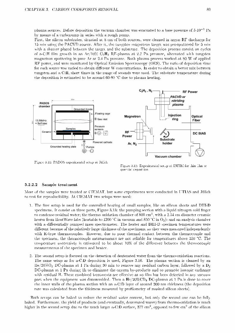
CHAPTER 3. CARBON CODEPOSITS REMOVAL 80
plasma sources. Before deposition the vacuum chamber was evacuated to a base pressure of 5·10=3 Paby means of a turbopump in series with a rough pump.First, the silicon substrates, situated at 8 cm of both sources, were cleaned in argon RF discharge for15 min using the PACVD source. After it, the tungsten magnetron target was pre-sputtered for 5 minwith a shutter placed between the target and the substrate. The deposition process consist on cyclesof a-C:H �lm growth in an Ar/10% C2H2 RF-plasma at 2.7 Pa pressure, alternated with tungstenmagnetron sputtering in pure Ar at 2.4 Pa pressure. Both plasma process worked at 80 W of appliedRF power, and were monitored by Optical Emission Spectroscopy (OES). The ratio of deposition timefor each source was varied to obtain di�erent W concentrations. In order to obtain a better mix betweentungsten and a-C:H, short times in the range of seconds were used. The substrate temperature duringthe deposition is estimated to be around 60-80 °C due to plasma heating.
Figure 3.11: PADOS experimental setup at JülichFigure 3.12: Experimental setup at INFIM for thin �lm se-quential deposition
3.2.2.2 Sample treatment
Most of the samples were treated at CIEMAT, but some experiments were conducted in UTIAS and Jülichto test for reproducibility. At CIEMAT two setups were used:
1. The �rst setup is used for the controlled heating of small samples, like on silicon sheets and DIII-Dspecimens. It consist on three parts, Figure 3.13: the pumping section with a liquid nitrogen cold �ngerto condense residual water; the thermo-oxidation chamber of 800 cm3, with a 2.54 cm diameter ceramicheater from HeatWave labs (heatable to 1200 °C in vacuum and 850 °C in O2); and an analysis chamberwith a di�erentially pumped mass spectrometer. The heater and DIII-D specimen temperatures weredi�erent because of the relatively large thickness of the specimens, so they were measured independentlywith K-type thermocouples. However, due to poor thermal contact between the thermocouple andthe specimen, the thermocouple measurements are not reliable for temperatures above 350 °C. Thetemperature uncertainty is estimated to be about 10% of the di�erence between the thermocouplemeasurements of the specimen and heater.
2. The second setup is focused on the detection of deuterated water from the thermo-oxidation reactions.The same setup as for a-C:D deposition is used, Figure 3.10. The plasma section is cleaned by anHe/20%O2 DC-plasma at 1 Pa during 30 min to remove any residual carbon layer, followed by a D2
DC-plasma at 1 Pa during 1h to eliminate the oxygen by-products and to promote isotopic exchangewith residual H. These combined treatments are e�ective as no �lm has been detected in any vacuumpart when the equipment was disassembled. Then a He/20%CD4 DC-plasma at 1 Pa is done to coverthe inner walls of the plasma section with an a-C:D layer of around 300 nm thickness (the depositionrate was calculated from the thickness measured by pro�lometry of masked silicon sheets).
Both setups can be baked to reduce the residual water content, but only the second one can be fullybaked. Furthermore, the yield of products (and eventually, deuterated water) from thermo-oxidation is muchhigher in the second setup due to the much larger a-C:D surface, 377 cm2, opposed to few cm2 of the silicon

CHAPTER 3. CARBON CODEPOSITS REMOVAL 81
Figure 3.13: Side view of experimental setup for samples thermo-oxidation: 1. Turbomolecular pump; 2. Gate valve; 3.Capacitance manometer (a) 1-1000 Torr, (b) 1-1000 mTorr; 4. Liquid nitrogen cold trap; 5. All-metal leak valve; 6. Bellowwith 1 mm pinhole; 7. Manometer (Bayard Alpert); 8. Ceramic heater; 9. Sample or DIII-D specimen; 10. Thermocoupleconnection. The vacuum chamber can be baked by silicone rubber covered heater.
and DIII-D samples of the �rst setup. Both setups are pumped down by means of separate turbomolecularpumps in series with roughing pumps, and are baked at 150 °C during a few days for many accumulated hoursto improve the residual vacuum and minimize the isotopic exchange between the produced deuterated waterand the natural, protonated water. In the �rst setup, for small samples, the pressure in both chambers is4-6·10-6 Pa. In the second setup, for large-area a-C:H �lm, the plasma and diagnostics section are at 1-3·10-6
Pa, while the analysis chamber reach 3-5·10-7 Pa. The di�erential pumping system is detailed in the nextsubsection.
Prior to each oxidation, both setups are baked up at 150 °C for 3 h. Then the sample in the �rstsetup, or the entire plasma section in the second, are slowly heated up (10 °C/min) until the experimenttemperature, and allowed to stabilize during 30 min. Finally, the communication to pumping system of thethermo-oxidation chamber is closed by a gate valve (item 2 in Figure 3.13 and item 1 in Figure 3.10), andO2 or NO2 are introduced by means of a leak valve (marked as �gas inlet� at both �gures) until the desiredpressure and left to react. Ideally, in the second setup, it would be desirable to operate with a continuousinjection of O2 or NO2 to pump out the products in order to be able to detect them in real time. Thisoperation mode was tested but many drawbacks were found, which eventually lead to a poorer deuteratedwater detection. Mainly, the working pressure is very large, but as the products yield is not large enough,their mass peaks are close to noise level in most cases. Moreover, an additional rough pump is needed througha bypass, as turbomolecular pumps are not able to work at so large pressures (in the order of kPa). Thisrough pump introduced a large quantity of impurities in the system from its mechanical oil, moreover, theproduced deuterated water could not be detected as it condensed on the bypass walls, which could not beproperly heated. Finally, when using NO2, as it is a very toxic gas, the exhaust has to be treated in a�lter with a basic water solution which could saturate quickly when working at the large �ux required forcontinuous operation.
At Jülich the PADOS setup, Figure 3.11, was slightly modi�ed to be used for thermo-oxidation. Bothelectrodes and the ceramic isolation can easily be dismounted, so that the grounded stainless steel heatingplate below the lower electrode can be directly used. It can be heated up to 700 °C, monitored with a type-Kthermocouple. At UTIAS the DIII-D specimen was placed in a vacuum chamber as in Figure 3.14, which wasthen pumped down to 10-4� 10-5 Pa. First, the initial D concentration was measured using LIDS, as explainedin the following subsection. After it the vacuum chamber was heated until the speci�c test temperature andbaked for 1 h to desorb gases from the chamber walls. The chamber was enclosed in a heating envelope sothe whole chamber with the specimen in it was heated to the test temperature measured using a K-typethermocouple attached to the outside. The exception was the 385 °C experiment, where only the specimen
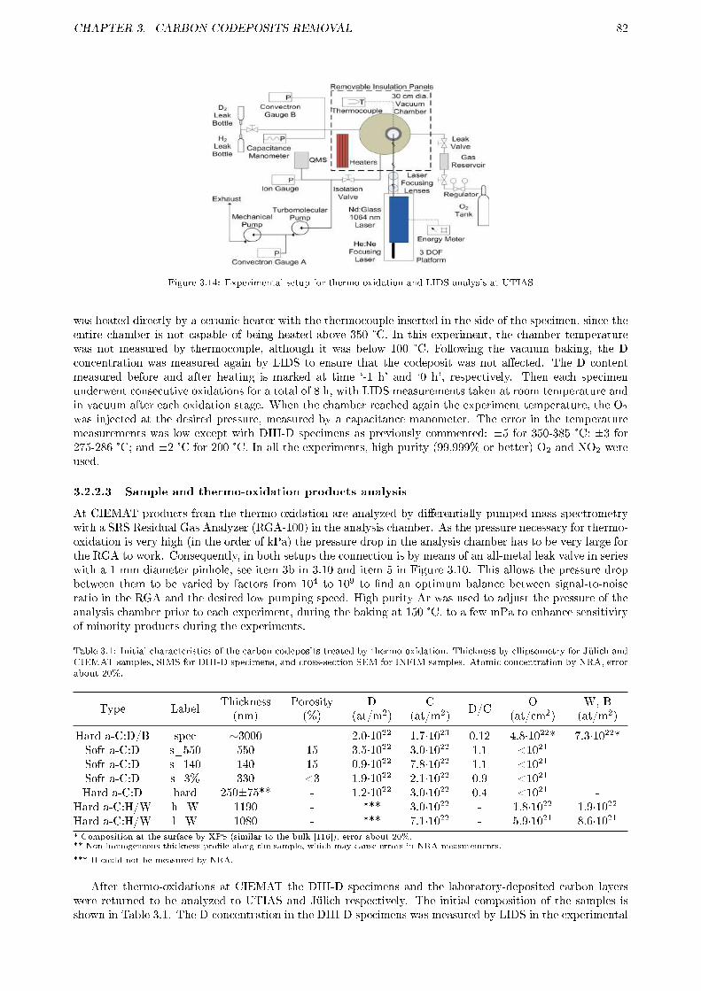
CHAPTER 3. CARBON CODEPOSITS REMOVAL 82
Figure 3.14: Experimental setup for thermo-oxidation and LIDS analysis at UTIAS
was heated directly by a ceramic heater with the thermocouple inserted in the side of the specimen, since theentire chamber is not capable of being heated above 350 °C. In this experiment, the chamber temperaturewas not measured by thermocouple, although it was below 100 °C. Following the vacuum baking, the Dconcentration was measured again by LIDS to ensure that the codeposit was not a�ected. The D contentmeasured before and after heating is marked at time `-1 h' and `0 h', respectively. Then each specimenunderwent consecutive oxidations for a total of 8 h, with LIDS measurements taken at room temperature andin vacuum after each oxidation stage. When the chamber reached again the experiment temperature, the O2
was injected at the desired pressure, measured by a capacitance manometer. The error in the temperaturemeasurements was low except with DIII-D specimens as previously commented: ±5 for 350-385 °C; ±3 for275-286 °C; and ±2 °C for 200 °C. In all the experiments, high purity (99,999% or better) O2 and NO2 wereused.
3.2.2.3 Sample and thermo-oxidation products analysis
At CIEMAT products from the thermo-oxidation are analyzed by di�erentially pumped mass spectrometrywith a SRS Residual Gas Analyzer (RGA-100) in the analysis chamber. As the pressure necessary for thermo-oxidation is very high (in the order of kPa) the pressure drop in the analysis chamber has to be very large forthe RGA to work. Consequently, in both setups the connection is by means of an all-metal leak valve in serieswith a 1 mm diameter pinhole, see item 3b in 3.10 and item 5 in Figure 3.10. This allows the pressure dropbetween them to be varied by factors from 104 to 109 to �nd an optimum balance between signal-to-noiseratio in the RGA and the desired low pumping speed. High purity Ar was used to adjust the pressure of theanalysis chamber prior to each experiment, during the baking at 150 °C, to a few mPa to enhance sensitivityof minority products during the experiments.
Table 3.1: Initial characteristics of the carbon codeposits treated by thermo-oxidation. Thickness by ellipsometry for Jülich andCIEMAT samples, SIMS for DIII-D specimens, and cross-section SEM for INFIM samples. Atomic concentration by NRA, errorabout 20%.
Type LabelThickness(nm)
Porosity(%)
D(at/m2)
C(at/m2)
D/CO
(at/cm2)W, B(at/m2)
Hard a-C:D/B spec ∼3000 - 2.0·1022 1.7·1023 0.12 4.8·1022* 7.3·1022*Soft a-C:D s_550 550 15 3.5·1022 3.0·1022 1.1 <1021 -Soft a-C:D s_140 140 15 0.9·1022 7.8·1022 1.1 <1021 -Soft a-C:D s_3% 330 <3 1.9·1022 2.1·1022 0.9 <1021 -Hard a-C:D hard 250±75** - 1.2·1022 3.0·1022 0.4 <1021 -
Hard a-C:H/W h_W 1190 - *** 3.0·1022 - 1.8·1022 1.9·1022
Hard a-C:H/W l_W 1080 - *** 7.1·1022 - 5.9·1021 8.6·1021
* Composition at the surface by XPS (similar to the bulk [116]), error about 20%.** Non homogeneous thickness pro�le along the sample, which may cause errors in NRA measurements.
*** H could not be measured by NRA.
After thermo-oxidations at CIEMAT the DIII-D specimens and the laboratory-deposited carbon layerswere returned to be analyzed to UTIAS and Jülich respectively. The initial composition of the samples isshown in Table 3.1. The D concentration in the DIII-D specimens was measured by LIDS in the experimental
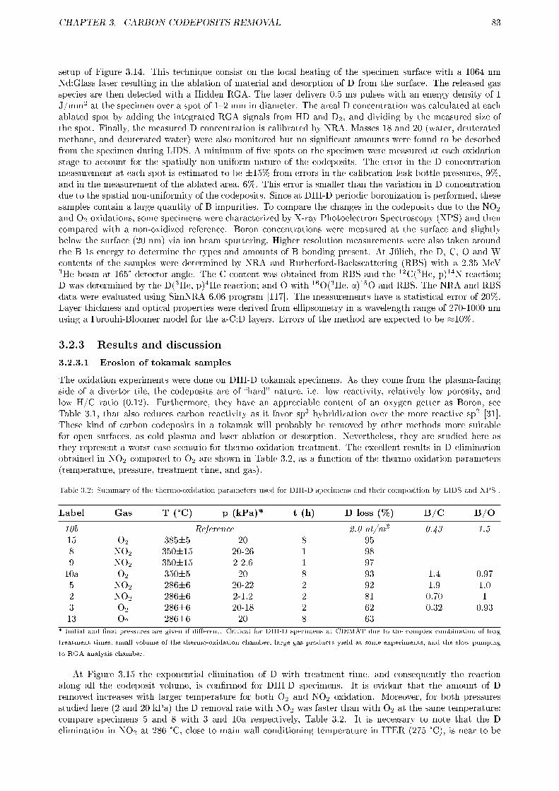
CHAPTER 3. CARBON CODEPOSITS REMOVAL 83
setup of Figure 3.14. This technique consist on the local heating of the specimen surface with a 1064 nmNd:Glass laser resulting in the ablation of material and desorption of D from the surface. The released gasspecies are then detected with a Hidden RGA. The laser delivers 0.5 ms pulses with an energy density of 1J/mm2 at the specimen over a spot of 1�2 mm in diameter. The areal D concentration was calculated at eachablated spot by adding the integrated RGA signals from HD and D2, and dividing by the measured size ofthe spot. Finally, the measured D concentration is calibrated by NRA. Masses 18 and 20 (water, deuteratedmethane, and deuterated water) were also monitored but no signi�cant amounts were found to be desorbedfrom the specimen during LIDS. A minimum of �ve spots on the specimen were measured at each oxidationstage to account for the spatially non-uniform nature of the codeposits. The error in the D concentrationmeasurement at each spot is estimated to be ±15% from errors in the calibration leak bottle pressures, 9%,and in the measurement of the ablated area, 6%. This error is smaller than the variation in D concentrationdue to the spatial non-uniformity of the codeposits. Since at DIII-D periodic boronization is performed, thesesamples contain a large quantity of B impurities. To compare the changes in the codeposits due to the NO2
and O2 oxidations, some specimens were characterized by X-ray Photoelectron Spectroscopy (XPS) and thencompared with a non-oxidized reference. Boron concentrations were measured at the surface and slightlybelow the surface (20 nm) via ion beam sputtering. Higher resolution measurements were also taken aroundthe B 1s energy to determine the types and amounts of B bonding present. At Jülich, the D, C, O and Wcontents of the samples were determined by NRA and Rutherford-Backscattering (RBS) with a 2.35 MeV3He beam at 165° detector angle. The C content was obtained from RBS and the 12C(3He, p)14N reaction;D was determined by the D(3He, p)4He reaction; and O with 16O(3He, α)15O and RBS. The NRA and RBSdata were evaluated using SimNRA 6.06 program [117]. The measurements have a statistical error of 20%.Layer thickness and optical properties were derived from ellipsometry in a wavelength range of 270-1000 nmusing a Forouhi-Bloomer model for the a-C:D layers. Errors of the method are expected to be ≈10%.
3.2.3 Results and discussion
3.2.3.1 Erosion of tokamak samples
The oxidation experiments were done on DIII-D tokamak specimens. As they come from the plasma-facingside of a divertor tile, the codeposits are of �hard� nature, i.e. low reactivity, relatively low porosity, andlow H/C ratio (0.12). Furthermore, they have an appreciable content of an oxygen getter as Boron, seeTable 3.1, that also reduces carbon reactivity as it favor sp3 hybridization over the more reactive sp2 [31].These kind of carbon codeposits in a tokamak will probably be removed by other methods more suitablefor open surfaces, as cold plasma and laser ablation or desorption. Nevertheless, they are studied here asthey represent a worst-case scenario for thermo-oxidation treatment. The excellent results in D eliminationobtained in NO2 compared to O2 are shown in Table 3.2, as a function of the thermo-oxidation parameters(temperature, pressure, treatment time, and gas).
Table 3.2: Summary of the thermo-oxidation parameters used for DIII-D specimens and their composition by LIDS and XPS .
Label Gas T (°C) p (kPa)* t (h) D loss (%) B/C B/O
10b Reference 2.0 at/m2 0.43 1.515 O2 385±5 20 8 958 NO2 350±15 20-26 1 989 NO2 350±15 2-2.6 1 9710a O2 350±5 20 8 93 1.4 0.975 NO2 286±6 20-22 2 92 1.9 1.02 NO2 286±6 2-1.2 2 81 0.70 13 O2 286±6 20-18 2 62 0.32 0.9313 O2 286±6 20 8 63
* Initial and �nal pressures are given if di�erent. Critical for DIII-D specimens at CIEMAT due to the complex combination of long
treatment times, small volume of the thermo-oxidation chamber, large gas products yield at some experiments, and the slow pumping
to RGA analysis chamber.
At Figure 3.15 the exponential elimination of D with treatment time, and consequently the reactionalong all the codeposit volume, is con�rmed for DIII-D specimens. It is evident that the amount of Dremoved increases with larger temperature for both O2 and NO2 oxidation. Moreover, for both pressuresstudied here (2 and 20 kPa) the D removal rate with NO2 was faster than with O2 at the same temperature:compare specimens 5 and 8 with 3 and 10a respectively, Table 3.2. It is necessary to note that the Delimination in NO2 at 286 °C, close to main wall conditioning temperature in ITER (275 °C), is near to be

CHAPTER 3. CARBON CODEPOSITS REMOVAL 84
completed in just 2 h treatment, specimens 2 and 5 at Table 3.2. On the other hand, the large and fast�exponential� D elimination and the limited pressure data from the experiment makes di�cult to studythe pressure dependence and the D removal rate for NO2. At 350 °C thermo-oxidation in NO2 show nearlycomplete depletion of D from the specimens 8 and 9 �at 20 and 2 kPa respectively, see Table 3.2� so nopressure dependence or D removal rate could be observed. But at 286 °C it seems to be a slightly weakerpressure dependence for NO2 than for O2, see Figure 3.16. However, additional experiments are necessary tostudy the D removal rate due to its exponential velocity. In the following subsection, experiments with shortoxidation times for di�erent laboratory-deposited carbon codeposits in NO2 and O2 are analyzed to verifythe superior codeposit elimination properties of the �rst. Finally, the thermo-oxidation of a DIII-D specimenat 400 °C was also tested, but the D removal was very poor. A blank experiment lead to the origin of thise�ect: the decomposition of NO2 to O2 and the oxidation of a copper connection of the oven due to its largetemperature, 600 °C, necessary to heat up the thick graphite specimen to 400°C. However, the direct reactionof NO2 with the graphite cannot be completely ruled out due to the large CO and CO2 production in thatexperiment.
The analysis of products from tokamak carbon codeposits removal is very important. Gaseous productswill be treated in a further point, but solid (non-volatile) products will be analyzed here. As previously stated,the composition of the remaining codeposit after thermo-oxidation treatment is very important for subsequenthydrogen isotopes absorption and reactive dust formation. DIII-D specimens have a large content of boronand oxygen at the surface, see Table 3.1. Similar B concentrations have been found by NRA in toroidallysymmetric tiles [116], 4-7·1022 at/m2, while oxygen was not analyzed by NRA. However, its concentrationis expected to be much lower in the bulk than at the surface due to absence of air contamination, whichhas a critical e�ect in XPS results. Notwithstanding, XPS analysis are very useful to compare relativecompositional changes at the surface after the thermo-oxidation treatment. In Figure 3.17 the XPS analysisfor specimens 3 and 5 oxidized at 286 °C at CIEMAT, specimen 10a oxidized at UTIAS, and a non-oxidizedreference specimen (10b), are presented (see Table 3.2 for their conditions). As expected, the concentrationof N in the codeposit measured by XPS was una�ected by oxidation with either O2 or NO2. Hence, itdoes not appear that thermo-oxidation with NO2 will lead to higher wall inventories of N compared withexposure to atmosphere. It was also found that the specimens with large D loss (> 80%) also experiencedincreases in B concentrations, e.g. specimen 5 had 92% D loss and its B/C concentration increase a factor of4.5, Figure 3.17. It is signi�cant that while specimens 5 and 10a lost around the same amount of D duringoxidation, the B/C ratio of specimen 5 is 40% larger. This suggests that NO2 �specimen 5� leads to higherC erosion rates than O2 �specimen 10a�, although a di�erent reaction time evolution in D and C removalfor the two oxidants cannot be ruled out due to the larger exposure (8 for 2 h) and temperature (350 for 286°C) in O2. Obviously, as can also be seen in Figure 3.17 oxygen content after thermo-oxidation increases inall the experiments, specially at larger D loss (specimens 5 and 10a). However, this oxygen do not seem to becompletely bonded to boron as all specimens have similar B/O ratios. Moreover, these ratios are close to 1,when stoichiometric would be 0.66 (B2O3). To elucidate boron bonding higher resolution XPS measurementsof B content were also made at these specimens, Figure 3.18. All specimens had two peaks around the B1senergy level. The peaks were centered at 191.3 eV and 188.6 eV for the non-oxidized reference specimen10a, while the oxidized specimens had peaks at 192.1�192.6 eV and 188.2�189.0 eV. The peaks at 191.3 and192.1�192.6 eV correspond with oxides; while the peaks at 188.2�189.0 eV correspond with borides, boranesand carboranes [118]. In the non-oxidized reference there were similar amounts of oxides and boranes. Butafter oxidation with either NO2 or O2 there were an increase in the oxide to borane ratio, specially in specimen5 which had the largest increase in total boron concentration and more oxidizing conditions (NO2).
3.2.3.2 Erosion of laboratory samples
As previously said, thermo-oxidation will be specially suited for the treatment of carbon codeposits in theremote parts of nuclear fusion devices. These codeposits are expected to be rich in hydrogen isotopes and witha low impurity content (soft a-C:H), as most impurities species have a sticking coe�cient (see glossary) of 1,or near it, so they will not be able to reach plasma-shadowed parts. Oppositely, a large part of hydrocarbonspecies have a sticking coe�cient lower than one (refer to section 1.4.2 for more details). Similar codepositscan be easily fabricated in laboratory and then treated by thermo-oxidation to calculate a more realisticestimation of the integration of this technique in the device maintenance schedule.
Four types of a-C:D �lms are studied: three of soft type with di�erent thickness and porosity; and a fourthof hard type, see Table 3.1 for their characteristics. The �nal deuterium and carbon content of the a-C:Dsamples studied is presented in Table 3.3 for each set of thermo-oxidation parameters. Unfortunately, somefactors will make the interpretation more complex: soft �lms show a partial delamination specially severeat some samples. This distorts some NRA measurements, and the worst cases have been eliminated. Eventhen, some cases are di�cult to interpret, e.g. at 275 °C and 3 min the D eliminated from 550 nm porous,

CHAPTER 3. CARBON CODEPOSITS REMOVAL 85
Figure 3.15: D concentration measured by LIDS versus oxida-tion time for DIII-D codeposits at (a) 286 °C, (b) 350 °C, (c)385�400 °C. Measurements shown at `-1 h' indicate D concen-tration in the specimen before vacuum baking or oxidation.The value shown for `0 h' is after vacuum baking at experi-ment temperature but prior to oxidation.
Figure 3.16: Comparison of D remaining content due to NO2
and O2 thermo-oxidation at various temperatures versus gaspressure.
Figure 3.17: Atomic concentration and ratios by XPS fromspecimens after thermo-oxidation. 10b is an un-treated spec-imen used as reference.
Figure 3.18: Percentages of boron bonding types by XPS fromspecimens after thermo-oxidation: oxygen and nitride versusboride, borane and carborane. 10b is an un-treated specimenused as reference.

CHAPTER 3. CARBON CODEPOSITS REMOVAL 86
Table 3.3: Summary of the thermo-oxidation parameters used and �nal carbon and deuterium composition by NRA for eachlaboratory sample studied. Partial delamination were found in some samples, which distorts their NRA measurements. Theworst cases are not presented.
Gas T (°C) p (kPa) t (min) D loss (%) C loss (%) D/C
s_550 s_140 s_3% hard s_550 s_140 s_3% hard s_550 s_140 s_3% hard
Reference ( in 1022at/m2) 3.5 0.9 1.9 1.2 3.0 0.78 2.1 3.0 1.1 1.1 0.9 0.4
NO2 350±5 20 3 100 100 47 100 89 100 29 94 0 0 0.66 0
10 100 100 - 99 100 100 - 87 0 0 - 0.04
O2 350±5 20 3 88 87 19 84 52 74 0 61 0.28 0.59 0.49 0.17
15 90 - 25 92 49 - 14 64 0.23 - 0.78 0.09
NO2 350±5 2 3 95 100 0 100 73 100 0 100 0.22 0 0.74 0
NO2 275±3 2 3 82 68 4 43 54 60 11 59 0.46 0.92 0.97 0.57
15 - - - 87 - - - 73 - - - 0.20
20 91 - 12 97 63 - 8 81 0.29 - 0.86 0.06
NO2 200±2 2 20 9 38 0 0 19 0 0 45 1.3 0.67 1.0 0.77
soft a-C:D, which developed a small �lm delamination, is larger than from 140 nm one (82% to 68%). Onthe other hand, hard a-C:D �lms did not delaminate, but they had a inhomogeneous thickness pro�le, so theerror in their NRA measurements could be very large. Consequently, only samples with similar pro�le hadbeen selected. The results in Table 3.3 show a good consistency, so no large errors are expected.
The �rst parameter analyzed is the temperature. Starting at the ITER divertor conditioning temperature,350 °C, in NO2 the �lm removal is complete, or very close to, even at 3 min and 2 kPa for porous, soft a-C:D�lms and hard �lms, see Table 3.3. At that temperature, under the same parameters none of the �lms arecompletely depleted in O2, but close to �80-90% D loss�, and they are far from complete �lm removal �50-75 % C loss�, Table 3.3. These results con�rm the previously observed faster D, and mainly C, eliminationby NO2 [16,104], which will reduce the possibility of the production of reactive dust residue from incompletelyremoved �lms. As expected, these removal rates in NO2 decrease with the temperature. As can be observedin Table 3.3, at 275 °C �ITER main wall conditioning temperature� the D elimination and �lm erosionare very fast for the same �lms (porous, soft and hard a-C:D �lms): in just three minutes 40-80 % of the Dand 55-60 % of the C are depleted. At this temperature the exponential reaction velocity, indicating reactionalong the entire volume of the �lm, is con�rmed: increasing the reaction time from 3 to 15 and 20 minutesleads to a much slower C and D elimination, Table 3.3. For example, hard a-C:D �lms at 3 min have loss the43% and 59 % of deuterium and carbon respectively, while at 20 min the loss have been increased to 97%and 81% respectively.
Experiments at a relatively low temperature as 200 °C have also been conducted to test for mild conditionsto reduce any possible impact on other vessel components, to reduce reaction with beryllium and graphite,and to test D elimination in remote parts not su�ciently heated during the device conditioning, as the vacuumvessel and under divertor cassettes. The results are important as they indicate a certain D elimination insoft, porous a-C:D �the ones developed in remote parts�, which gives a removal rate of 3·1018 at/m2s forboth thickness, corroborating their linear relationship [21, 105]. Notwithstanding, at this low temperaturean interesting e�ect is more evident: C seems to be preferentially eliminated in most a-C:D types, as theirD/C ratio increase. This may be included into a more general e�ect speci�c to NO2 thermo-oxidation: Cis preferentially removed in the initial moments, when the D elimination is already low. As can be seen inTable 3.3, at lower temperatures this e�ect is obvious in the D/C ratio increase except in thin, porous, softa-C:D, where the thermo-oxidation is more developed (D loss is 38%). At larger temperatures and shortertimes, 275 °C and 3 min, this e�ect continues to be observed in the less reactive a-C:D types like hard andlow porosity types, as D/C rises from 0.4 to 0.57 and from 0.9 to 0.97, respectively, see Table 3.3. Evenmore, initial D content has to be of importance as hard a-C:D samples (their D/C is less than half of softtypes) exhibit this e�ect even at medium D depletion, 43% at 275 °C and 3 min. On the contrary, in oxygenthis e�ect is never observed, at 350 °C and 3 min even the more resilient type, low porosity, soft a-C:D,present a small D elimination (19%) but no carbon elimination, Table 3.3. These results suggest that during

CHAPTER 3. CARBON CODEPOSITS REMOVAL 87
thermo-oxidation with NO2 a part of the C is necessary to be eliminated �rst for the D elimination to initiate,and perhaps it is limited to temperatures below 350 °C. As this e�ect is more evident in samples rich on theusually less reactive sp3 bonds (refer to section 1.2.2 for details), as hard a-C:D, probably C atoms bondedin this way are the responsible.
Other parameters have also been studied. The porosity, which represent the inner surface available toreaction with the gas, has been demonstrated to be of paramount importance, as the erosion and D depletionrate is much slower in low porosity codeposits. For instance, thermo-oxidation is slower at all conditionsfor low porosity, soft a-C:D than for the less reactive hard a-C:D, compare both types in Table 3.3. Theporosity of these hard a-C:D �lms from DC-plasma has not been determined, but their D and C depletionrates indicate that it has to be larger than 3% (as low porosity, soft a-C:D from Jülich), and probably closeto 15% (as porous, soft a-C:D from Jülich). This is demonstrated as D is eliminated more slowly from thesehard a-C:D �lms than from soft, porous ones of similar thickness, e.g. at 275 °C and 3 min the 43% of D hasbeen eliminated from hard a-C:D, while for 140 nm porous, soft a-C:D the 68% of D has been depleted, seeTable 3.3. In agreement with results in tokamak samples [104], the pressure has almost no consequences, buthere it is demonstrated that it keeps only true for porous �lms, as tokamak �lms are, not for low porosity�lms. At 350 °C and 3 min in those low porosity �lms the pressure e�ect is very evident, as at 20 kPathe 47% of D and 29% of C have been removed while at 2 kPa no D and C seems to be removed withinexperimental errors, see Table 3.3. This pressure dependence is likely related to the lower quantity of reactivegas at the surface of the codeposit caused by the change from volume reaction to surface reaction due to thelow porosity.
Figure 3.19: Temperature dependance �tted by Arrheniusequation of D and C removal rates by thermo-oxidation in2 kPa NO2 on 550 nm, 15% porosity, soft a-C:D �lm.
Figure 3.20: Pressure dependance �tted by Langmuirisotherm equation of D and C removal rates by thermo-oxidation in NO2 at 350 °C on 550 nm, 15% porosity, softa-C:D �lm.
Deuterium and carbon removal rate and their reaction parameters were studied in collaboration with Dr.Möller in Jülich [105] in order to extrapolate to ITER divertor conditions. However, even at 3 minutes, theminimum operational time to address gas pump in and out which last around 20-30 s, the �lm removal in NO2
was nearly complete at 275-350 °C for most samples, as can be deduced from Table 3.3. This so fast reactionand the few points available due to lack of NRA analysis time will cause a large error in the calculation ofthe reaction parameters and removal rates. Considering this, the activation energy for D and C eliminationwere estimated in 0.76 and 0.79 eV respectively, by �tting the removal rates at 2 kPa in Figure 3.19 to theArrhenius equation. Both activation energies are low and of similar value, as suggested by the fast eliminationof C and D even at low temperatures, and in contrast with O2, whose removal rate for C is much lower thanfor NO2. To describe the adsorption and subsequent reaction of the NO2 along pore surfaces, the removalrates at 350 °C was �tted to a Langmuir adsorption isotherm, Figure 3.20, using as a third point the absenceof �lm removal at 10-4 Pa. This isotherm shows the low pressure dependence of NO2 thermo-oxidation,mostly for D. At 50 Pa the estimated removal rate would be ∼16 and ∼7.5 ·1019 at/m2min, for D and Crespectively, but more data will be needed to con�rm this assumption. The use of so a low pressure wouldmean a good compromise between fast D and C removal rate and reduced damage to in-vessel componentsin ITER. However, this removal rate is only valid for soft a-C:D codeposits of 15 % porosity. In order toextrapolate for ITER �and similar present and future devices� soft a-C:D:T codeposits in remote partsthe porosity of these �lms needs to be estimated. The porosity of a-C:D codeposits depend mainly on thedeposition gas pressure. In ITER divertor the pressure will be between 5-15 Pa, which corresponds to aporosity of 9-20% in pure CD4 plasma in PADOS device [105]. Nevertheless, in ITER (and any other device)

CHAPTER 3. CARBON CODEPOSITS REMOVAL 88
the partial pressure of a-C:D:T �lm precursors (CxDyTx) will be orders of magnitude lower, so the expectedporosity could be even larger. Finally, the estimated porosity, Langmuir isotherm and Arrhenius equationwere used to predict the thermo-oxidation time required for 95% D elimination from ITER codeposits inremote parts at 50 Pa [105]. At 350 °C would be between 3-5 min, at 275 °C 15-25 min, and 274-457 minat 200 °C. It is necessary to note that these times are independent of the initial thickness of the codepositsas long as their porosity is large enough. Furthermore, these required times will be lower due to the largerreactivity of in-situ tokamak codeposit removal already described [115]. This will be specially true for 350and 275 °C due to the uncertainties in the calculation of their removal rates, precisely because of the fastand complete D depletion in NO2.
Table 3.4: Summary of the thermo-oxidation parameters used and �nal composition by NRA for a-C:H/W laboratory samples.
Gas T (°C) p (kPa) t (min) C loss (%) W loss (%) O gain (%) W/C W/O
h_W l_W h_W l_W h_W l_W h_W l_W h_W l_W
Reference ( in 1022at/m2) 3.0 7.1 1.9 0.86 1.8 0.59 0.63 0.12 1.0 1.5
NO2 350±5 20 15 7 - 5 - 137 - 0.64 - 0.41 -
O2 350±5 20 15 0 - 5 - 147 - 0.48 - 0.39 -
NO2 350±5 2 15 0 10 20 5 128 300 0.48 0.13 0.36 0.35
NO2 275±3 2 15 8 2 10 0 107 161 0.61 0.12 0.44 0.56
Thermo-oxidation of hard a-C:H/W samples was also tested in order to study the behavior of a complexand resilient codeposit. They can be expected on open surfaces in the divertor of a device like ITER.The results of di�erent thermo-oxidation treatments are shown in Table 3.4. The samples were depositedusing C2H2, but the protium could not be analyzed by NRA, so the hydrogen loss could not be measured.Nevertheless, these codeposits would be removed by other techniques, probably cold plasma, so the hydrogenisotopes elimination by thermo-oxidation is not an issue for those codeposits. Unfortunately, all samplesexhibit a large delamination from the silicon surface after treatment due to the large volumetric gain of the�lms by oxygen uptake. This is true in samples with high W content (100-150% gain), which already hada large initial O content (1.8·1022 at/m2), and is specially evident in samples with lower initial W and Ocontent (up to 300% gain), Table 3.4. The initial O content is associated to W because during the sputteringdeposition tungsten is known to react easily with water and air impurities. Moreover, the W/O ratio, close tostoichiometric 0.33, points to the formation of WO3, specially at 350 °C. Other interesting fact can be deducedfrom the extremely low C elimination and slight changes in W/C ratio as can be seen in Table 3.4: W mustsomehow hinder its reaction with O2 and NO2 even when most of the W has been completely oxidized to WO3.However, both e�ects �oxidation of W and low C removal� are most likely caused by the deposition schemewhich produces a few nm multilayer structure, see experimental section 3.2.2, not a real W atomic dispersionas in real nuclear fusion devices (more details are given in section 3.4.3 and Figure 3.41c, where the e�ectof these multilayers are more evident). Finally, the observed W loss would probably comes from the lossescaused by �lm delamination and partial sublimation of WO3. These results point to a large dust productionduring thermo-oxidation treatment from the hydrogenated carbon and tungsten codeposits. Nonetheless, thislarge dust production will be common to any other tritium removal method, and mitigation procedures forthe removal of this dust must be undertaken anyway. Other methods whose dust production is lower, likecold plasma, should be used to eliminate these codeposits on the open surfaces prior to thermo-oxidationtreatment.
3.2.3.3 Gas products
Thermo-oxidation of carbon codeposits release gaseous products mainly, only metallic impurities (Be, B, W,Fe, etc) will create solid products. The residue left by B and W was their oxides as found at the previoussubsections. The gaseous products are carbon oxides, CO and CO2, but from hydrogen isotopes could bemany: molecular hydrogen, water and hydrocarbons. As previously stated, in a future nuclear fusion devicemolecular hydrogen and hydrocarbons are the products whose recovery and recycling of hydrogen isotopesare easier (paramount for economy of tritium). Water would be more expensive and more dangerous to treatdue to the hazardous tritiated water (see glossary for details). In thermo-oxidation by O2 the main productfound has been water [12,17�19], so an identi�cation and quanti�cation of thermo-oxidation products in NO2
is paramount for the application of this technique to future nuclear fusion devices. For this task the setup
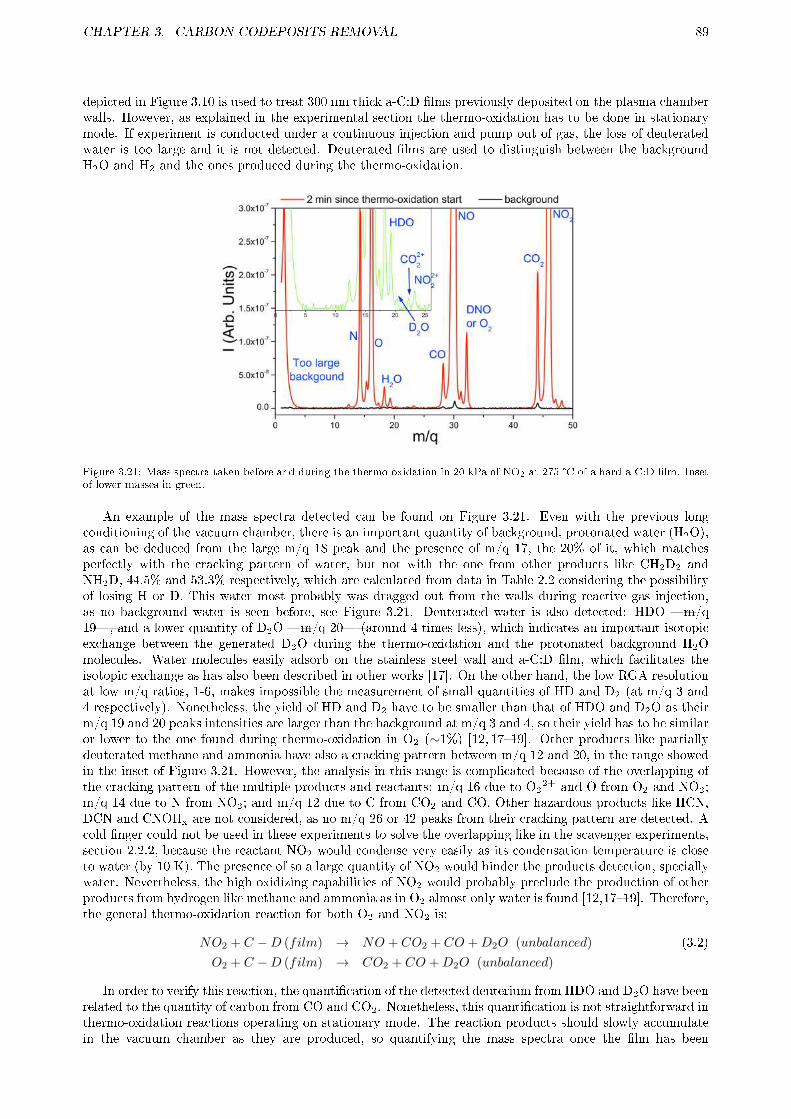
CHAPTER 3. CARBON CODEPOSITS REMOVAL 89
depicted in Figure 3.10 is used to treat 300 nm thick a-C:D �lms previously deposited on the plasma chamberwalls. However, as explained in the experimental section the thermo-oxidation has to be done in stationarymode. If experiment is conducted under a continuous injection and pump out of gas, the loss of deuteratedwater is too large and it is not detected. Deuterated �lms are used to distinguish between the backgroundH2O and H2 and the ones produced during the thermo-oxidation.
Figure 3.21: Mass spectra taken before and during the thermo-oxidation in 20 kPa of NO2 at 275 °C of a hard a-C:D �lm. Insetof lower masses in green.
An example of the mass spectra detected can be found on Figure 3.21. Even with the previous longconditioning of the vacuum chamber, there is an important quantity of background, protonated water (H2O),as can be deduced from the large m/q 18 peak and the presence of m/q 17, the 20% of it, which matchesperfectly with the cracking pattern of water, but not with the one from other products like CH2D2 andNH2D, 44.5% and 53.3% respectively, which are calculated from data in Table 2.2 considering the possibilityof losing H or D. This water most probably was dragged out from the walls during reactive gas injection,as no background water is seen before, see Figure 3.21. Deuterated water is also detected: HDO �m/q19�, and a lower quantity of D2O �m/q 20� (around 4 times less), which indicates an important isotopicexchange between the generated D2O during the thermo-oxidation and the protonated background H2Omolecules. Water molecules easily adsorb on the stainless steel wall and a-C:D �lm, which facilitates theisotopic exchange as has also been described in other works [17]. On the other hand, the low RGA resolutionat low m/q ratios, 1-6, makes impossible the measurement of small quantities of HD and D2 (at m/q 3 and4 respectively). Nonetheless, the yield of HD and D2 have to be smaller than that of HDO and D2O as theirm/q 19 and 20 peaks intensities are larger than the background at m/q 3 and 4, so their yield has to be similaror lower to the one found during thermo-oxidation in O2 (∼1%) [12, 17�19]. Other products like partiallydeuterated methane and ammonia have also a cracking pattern between m/q 12 and 20, in the range showedin the inset of Figure 3.21. However, the analysis in this range is complicated because of the overlapping ofthe cracking pattern of the multiple products and reactants: m/q 16 due to O2
2+ and O from O2 and NO2;m/q 14 due to N from NO2; and m/q 12 due to C from CO2 and CO. Other hazardous products like HCN,DCN and CNOHx are not considered, as no m/q 26 or 42 peaks from their cracking pattern are detected. Acold �nger could not be used in these experiments to solve the overlapping like in the scavenger experiments,section 2.2.2, because the reactant NO2 would condense very easily as its condensation temperature is closeto water (by 10 K). The presence of so a large quantity of NO2 would hinder the products detection, speciallywater. Nevertheless, the high oxidizing capabilities of NO2 would probably preclude the production of otherproducts from hydrogen like methane and ammonia as in O2 almost only water is found [12,17�19]. Therefore,the general thermo-oxidation reaction for both O2 and NO2 is:
NO2 + C −D (film) → NO + CO2 + CO +D2O (unbalanced) (3.2)
O2 + C −D (film) → CO2 + CO +D2O (unbalanced)
In order to verify this reaction, the quanti�cation of the detected deuterium from HDO and D2O have beenrelated to the quantity of carbon from CO and CO2. Nonetheless, this quanti�cation is not straightforward inthermo-oxidation reactions operating on stationary mode. The reaction products should slowly accumulatein the vacuum chamber as they are produced, so quantifying the mass spectra once the �lm has been
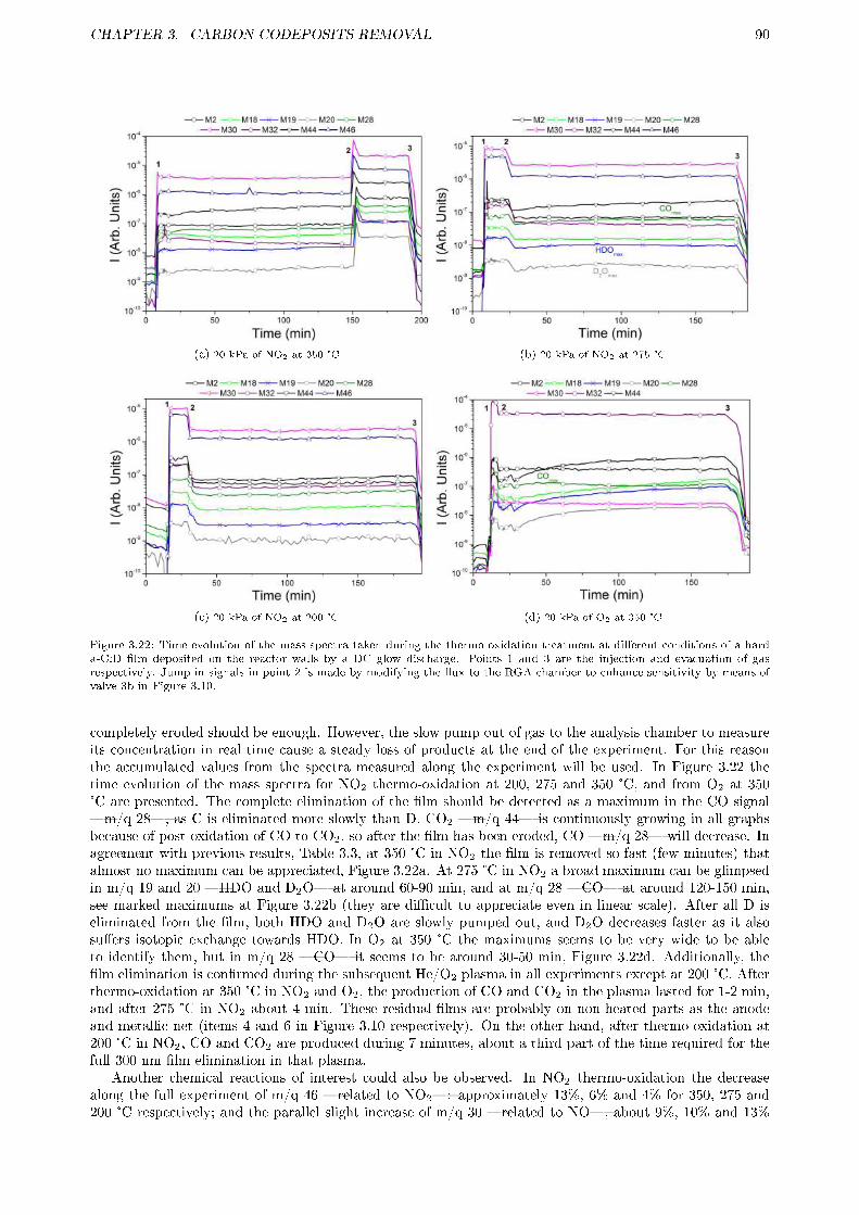
CHAPTER 3. CARBON CODEPOSITS REMOVAL 90
(a) 20 kPa of NO2 at 350 °C (b) 20 kPa of NO2 at 275 °C
(c) 20 kPa of NO2 at 200 °C (d) 20 kPa of O2 at 350 °C
Figure 3.22: Time evolution of the mass spectra taken during the thermo-oxidation treatment at di�erent conditions of a harda-C:D �lm deposited on the reactor walls by a DC glow discharge. Points 1 and 3 are the injection and evacuation of gasrespectively. Jump in signals in point 2 is made by modifying the �ux to the RGA chamber to enhance sensitivity by means ofvalve 3b in Figure 3.10.
completely eroded should be enough. However, the slow pump out of gas to the analysis chamber to measureits concentration in real time cause a steady loss of products at the end of the experiment. For this reasonthe accumulated values from the spectra measured along the experiment will be used. In Figure 3.22 thetime evolution of the mass spectra for NO2 thermo-oxidation at 200, 275 and 350 °C, and from O2 at 350°C are presented. The complete elimination of the �lm should be detected as a maximum in the CO signal�m/q 28�, as C is eliminated more slowly than D. CO2 �m/q 44� is continuously growing in all graphsbecause of post-oxidation of CO to CO2, so after the �lm has been eroded, CO �m/q 28� will decrease. Inagreement with previous results, Table 3.3, at 350 °C in NO2 the �lm is removed so fast (few minutes) thatalmost no maximum can be appreciated, Figure 3.22a. At 275 °C in NO2 a broad maximum can be glimpsedin m/q 19 and 20 �HDO and D2O� at around 60-90 min, and at m/q 28 �CO� at around 120-150 min,see marked maximums at Figure 3.22b (they are di�cult to appreciate even in linear scale). After all D iseliminated from the �lm, both HDO and D2O are slowly pumped out, and D2O decreases faster as it alsosu�ers isotopic exchange towards HDO. In O2 at 350 °C the maximums seems to be very wide to be ableto identify them, but in m/q 28 �CO� it seems to be around 30-50 min, Figure 3.22d. Additionally, the�lm elimination is con�rmed during the subsequent He/O2 plasma in all experiments except at 200 °C. Afterthermo-oxidation at 350 °C in NO2 and O2, the production of CO and CO2 in the plasma lasted for 1-2 min,and after 275 °C in NO2 about 4 min. These residual �lms are probably on non-heated parts as the anodeand metallic net (items 4 and 6 in Figure 3.10 respectively). On the other hand, after thermo-oxidation at200 °C in NO2, CO and CO2 are produced during 7 minutes, about a third part of the time required for thefull 300 nm �lm elimination in that plasma.
Another chemical reactions of interest could also be observed. In NO2 thermo-oxidation the decreasealong the full experiment of m/q 46 �related to NO2�: approximately 13%, 6% and 4% for 350, 275 and200 °C respectively; and the parallel slight increase of m/q 30 �related to NO�, about 9%, 10% and 13%
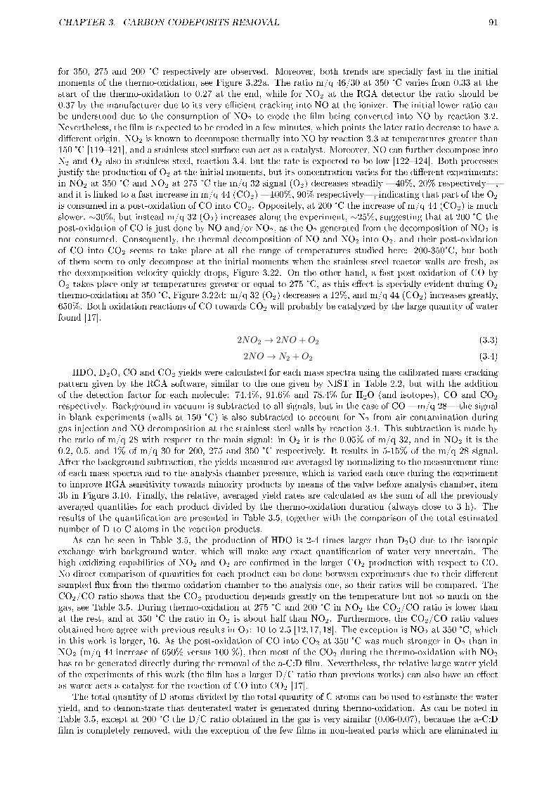
CHAPTER 3. CARBON CODEPOSITS REMOVAL 91
for 350, 275 and 200 °C respectively are observed. Moreover, both trends are specially fast in the initialmoments of the thermo-oxidation, see Figure 3.22a. The ratio m/q 46/30 at 350 °C varies from 0.33 at thestart of the thermo-oxidation to 0.27 at the end, while for NO2 at the RGA detector the ratio should be0.37 by the manufacturer due to its very e�cient cracking into NO at the ionizer. The initial lower ratio canbe understood due to the consumption of NO2 to erode the �lm being converted into NO by reaction 3.2.Nevertheless, the �lm is expected to be eroded in a few minutes, which points the later ratio decrease to have adi�erent origin. NO2 is known to decompose thermally into NO by reaction 3.3 at temperatures greater than150 °C [119�121], and a stainless steel surface can act as a catalyst. Moreover, NO can further decompose intoN2 and O2 also in stainless steel, reaction 3.4, but the rate is expected to be low [122�124]. Both processesjustify the production of O2 at the initial moments, but its concentration varies for the di�erent experiments:in NO2 at 350 °C and NO2 at 275 °C the m/q 32 signal (O2) decreases steadily �40%, 20% respectively�,and it is linked to a fast increase in m/q 44 (CO2) �100%, 90% respectively�, indicating that part of the O2
is consumed in a post-oxidation of CO into CO2. Oppositely, at 200 °C the increase of m/q 44 (CO2) is muchslower, ∼30%, but instead m/q 32 (O2) increases along the experiment, ∼25%, suggesting that at 200 °C thepost-oxidation of CO is just done by NO and/or NO2, as the O2 generated from the decomposition of NO2 isnot consumed. Consequently, the thermal decomposition of NO and NO2 into O2, and their post-oxidationof CO into CO2 seems to take place at all the range of temperatures studied here: 200-350°C, but bothof them seem to only decompose at the initial moments when the stainless steel reactor walls are fresh, asthe decomposition velocity quickly drops, Figure 3.22. On the other hand, a fast post-oxidation of CO byO2 takes place only at temperatures greater or equal to 275 °C, as this e�ect is specially evident during O2
thermo-oxidation at 350 °C, Figure 3.22d: m/q 32 (O2) decreases a 12%, and m/q 44 (CO2) increases greatly,650%. Both oxidation reactions of CO towards CO2 will probably be catalyzed by the large quantity of waterfound [17].
2NO2 → 2NO +O2 (3.3)
2NO → N2 +O2 (3.4)
HDO, D2O, CO and CO2 yields were calculated for each mass spectra using the calibrated mass crackingpattern given by the RGA software, similar to the one given by NIST in Table 2.2, but with the additionof the detection factor for each molecule: 74.4%, 91.6% and 78.4% for H2O (and isotopes), CO and CO2
respectively. Background in vacuum is subtracted to all signals, but in the case of CO �m/q 28� the signalin blank experiments (walls at 150 °C) is also subtracted to account for N2 from air contamination duringgas injection and NO decomposition at the stainless steel walls by reaction 3.4. This subtraction is made bythe ratio of m/q 28 with respect to the main signal: in O2 it is the 0.05% of m/q 32, and in NO2 it is the0.2, 0.5, and 1% of m/q 30 for 200, 275 and 350 °C respectively. It results in 5-15% of the m/q 28 signal.After the background subtraction, the yields measured are averaged by normalizing to the measurement timeof each mass spectra and to the analysis chamber pressure, which is varied each once during the experimentto improve RGA sensitivity towards minority products by means of the valve before analysis chamber, item3b in Figure 3.10. Finally, the relative, averaged yield rates are calculated as the sum of all the previouslyaveraged quantities for each product divided by the thermo-oxidation duration (always close to 3 h). Theresults of the quanti�cation are presented in Table 3.5, together with the comparison of the total estimatednumber of D to C atoms in the reaction products.
As can be seen in Table 3.5, the production of HDO is 2-4 times larger than D2O due to the isotopicexchange with background water, which will make any exact quanti�cation of water very uncertain. Thehigh oxidizing capabilities of NO2 and O2 are con�rmed in the larger CO2 production with respect to CO.No direct comparison of quantities for each product can be done between experiments due to their di�erentsampled �ux from the thermo-oxidation chamber to the analysis one, so their ratios will be compared. TheCO2/CO ratio shows that the CO2 production depends greatly on the temperature but not so much on thegas, see Table 3.5. During thermo-oxidation at 275 °C and 200 °C in NO2 the CO2/CO ratio is lower thanat the rest, and at 350 °C the ratio in O2 is about half than NO2. Furthermore, the CO2/CO ratio valuesobtained here agree with previous results in O2: 10 to 2.5 [12,17,18]. The exception is NO2 at 350 °C, whichin this work is larger, 16. As the post-oxidation of CO into CO2 at 350 °C was much stronger in O2 than inNO2 (m/q 44 increase of 650% versus 100 %), then most of the CO2 during the thermo-oxidation with NO2
has to be generated directly during the removal of the a-C:D �lm. Nevertheless, the relative large water yieldof the experiments of this work (the �lm has a larger D/C ratio than previous works) can also have an e�ectas water acts a catalyst for the reaction of CO into CO2 [17].
The total quantity of D atoms divided by the total quantity of C atoms can be used to estimate the wateryield, and to demonstrate that deuterated water is generated during thermo-oxidation. As can be noted inTable 3.5, except at 200 °C the D/C ratio obtained in the gas is very similar (0.06-0.07), because the a-C:D�lm is completely removed, with the exception of the few �lms in non-heated parts which are eliminated in

CHAPTER 3. CARBON CODEPOSITS REMOVAL 92
the subsequent He/O2 plasma. But at 200 °C the D/C ratio in the gas is 0.043, which indicates that at thistemperature NO2 seems to eliminate C more quickly than D during the initial part of the thermo-oxidation,as previously detected on silicon samples, Table 3.3. Anyway, as previously commented, about two thirdsof the �lm volume is completely eroded at 200 °C, which is another indicator of the possibility of usingthermo-oxidation with NO2 at mild temperatures in a future nuclear fusion device.
Table 3.5: Averaged yield rate (in arbitrary units, see text for the averaging process explanation) of main carbon and deuteriumcontaining products, quanti�ed during 20 kPa thermo-oxidation of hard a-C:D �lms at di�erent conditions. Ratios of CO2 toCO and HDO to D2O have also been included. Total C and D columns have been calculated as the sum of CO plus CO2 andHDO plus D2O molecules respectively. D/C (gas) ratio has been calculated by dividing total D by total C columns.
Gas T (°C) CO CO2 CO2/CO Total C HDO D2O HDO/D2O Total D D/C (gas)
O2 350±5 0.17 1.3 8.0 1.5 0.048 0.028 1.7 0.10 0.069NO2 350±5 0.20 3.2 16 3.4 0.14 0.033 4.2 0.20 0.060NO2 275±3 0.34 1.6 4.7 2.0 0.087 0.021 4.2 0.13 0.066NO2 200±2 0.15 0.60 3.9 0.76 0.020 0.0064 3.1 0.033 0.043
Notwithstanding, as the a-C:D �lm has been completely removed the D/C ratio detected in the gasshould be 0.4 like the �lm, but the obtained values are between a factor 5-10 lower. However, these valuesare su�ciently high to demonstrate that the deuterated water comes from thermo-oxidation of a-C:D �lm.Many factors are expected to have an e�ect:
� The main reason is the complexity of achieving an homogeneous heating of all vacuum chamber piecesalong all sections. A spherical chamber would allow a more homogeneous heating as in [12]. This havetwo e�ects: �rst, it is related to the incomplete water conditioning, so the large isotopic exchange ofthe produced deuterated water and the background water will add a large error in the detection of thedeuterated water; and second, it is highly possible that a part of the deuterated water condenses in acold part and is, therefore, not detected.
� Even when many measures have been taken to reduce the background water (see m/q 18 signal inFigure 3.21) and a CaSO4 �lter was inserted in the gas inlet, the H2O and H2 dragged out fromstainless steel walls are still very important, note the large m/q 2 signal in the same Figure. This e�ectwill cause an error on the detected deuterated water by isotopic exchange. Furthermore, the drag outseems to be specially important for NO2, as its HDO/D2O ratio is between 2-3 times than of O2, seeTable 3.5.
� Water has a slower pumping velocity than the rest of products due to its easy sticking at the chamberwalls. The concentration in the analysis chamber will therefore be lower than the rest of the species.
In previous subsections the pressure showed only a small in�uence in NO2 thermo-oxidation and its products,so it was not further tested.
3.2.4 Summary and future work
Thermo-oxidation in NO2 has been shown to be very e�ective to remove all kinds of a-C:H �lms in a reallyfast way (minutes) and even at temperatures as low as 200 °C, as those expected in remote parts of futurenuclear fusion devices. The following features have been described:
� It has been con�rmed the relationship of �lm porosity with the previously observed reaction in volumeof thermo-oxidation. Most �lms showed an exponential depletion of carbon and hydrogen proportionalto their initial content, with almost no dependence on the gas pressure. On the other hand, �lms withlow porosity presented a larger pressure dependence showing that the thermo-oxidation is then limitedto the surface.
� Film porosity resulted to be the main parameter for the erosion rate, as hard a-C:D �lms were morequickly eroded than low-porosity, soft a-C:D �lms, which are more reactive.
� Thermo-oxidation by O2 is very limited in temperature, which will hinder the codeposit removal atmain wall and remote parts. For instance, at 286 °C a limit of 60 % of D depletion was found aftermany hours. Furthermore, its carbon erosion rate is much slower than hydrogen one, so it could leavereactive carbon-rich codeposits which can later absorb hydrogen during plasma operation.

CHAPTER 3. CARBON CODEPOSITS REMOVAL 93
� NO2 thermo-oxidation has shown a good erosion velocity for mixed codeposits, even with getters asboron that also reduces the reactivity of carbon. However, this treatment will result in the creation ofdust as the �lm can easy delaminate because of the formation of oxides like WO3 and B2O3. Althoughthey are not very reactive they will accumulate and could induce plasma contamination, refer to sec-tion 1.3 for full explanation. These mixed codeposits develop only at the open surfaces, which will beroutinely treated by other removal methods with lower dust production (mainly cold plasma), so theywill not be a problem as long as these removal methods are programmed before thermo-oxidation.
� It seems that NO2 at temperatures lower than 350 °C reacts initially with the sp3 bonded carbon ofthe codeposits, as in the initial moments more carbon is eliminated than deuterium. This was speciallyevident at hard a-C:D �lms (sp3 rich).
� NO2 decomposes slowly in stainless steels walls to NO and O2, and it also allows the post-oxidation ofCO to CO2. Moreover, at >275 °C the previously formed O2 also enhances the post-oxidation of CO,specially evident in the thermo-oxidation in O2 at 350 °C. Both post-oxidations are probably catalyzedby the relatively large amount of water found and produced.
� At the temperatures studied here most of the hydrogen isotopes in the �lm will be eliminated in theform of water using O2 or NO2, specially dangerous for tritium. This, together with dust formationfrom mixed codeposits, will limit thermo-oxidation treatment to the removal of codeposits not accessibleto other water-production-free techniques, like those in remote parts. Notwithstanding, these �lms arevery reactive and could be removed in a matter of minutes. The conditioning temperature could bereduced to limit the possible damage to other in-vessel components as the required time continues tobe easily achievable (just a hours will be required even at only 200 °C).
It is necessary to note that in-situ tokamak carbon codeposit removal will be much more e�ective than theexperiments done in this work due to air contamination. So most probably even an overnight treatment willbe possible as long as the walls are kept hot as in JET tokamak (200 °C), routinely used to improve waterconditioning. The schedule would be: a pre-treatment to remove most codeposits in open surfaces, followedby a thermo-oxidation in NO2 during a few minutes to eliminate the codeposits in remote parts, and theremaining time for chamber operational status recovery. Although this work is almost �nished some featurescan be further developed:
1. NO2 thermo-oxidation at 200 °C and lower temperatures should be explored to reduce in-vessel damage.The study must be focused in soft a-C:D �lms, like those expected to develop in remote parts, toinvestigate if due to its much larger hydrogen concentration (H/C >1) at some point only carbon iseliminated and then the hydrogen recombines and is eliminated in its molecular form.
2. NO2 thermo-oxidation at as low pressures as 50 Pa should also be investigated to reduce in vesseldamage.
3. Thicker and medium porosity (5-10%) �lms should be treated to calculate in a more precise way theactivation energy for D and C, and the isotherms at the main temperatures: 350 °C, 275 °C and 200°C. These kind of �lms should be not so quickly eliminated, but the reaction must continue being alongall the volume.
These studies could not be done in the current setup at CIEMAT as soft a-C:D �lm could not be depositedin a DC-plasma. The use of samples with soft a-C:D �lms will not yield su�cient products to be detected bymass spectrometry. Other devices like PADOS could not use NO2 and are too large to be e�ciently bakedto avoid water condensation. A possibility now under study is the coating of the entire heatable tube of thethermo-oxidation section with a soft a-C:D �lm.
3.3 LASER ABLATION
As stated in the introduction, section 1.4.3, laser removal techniques are based on localized surface treatment.They are very e�ective to treat thick codeposits at speci�c places like the secondary divertor region at the topof nuclear fusion devices. In this way, a laser tool on a multipurpose remote handling deployer does not haveto treat a wide surface area, as if the whole wall surface needs to be treated many days would be required.Other techniques, like cold plasma, explained previously at section 3.1, are more suited to treat the wholewall surface, but not very thick codeposits. Nevertheless, the main advantages of laser techniques are thelow substrate damage, and the recovery of the hydrogen isotopes from the codeposits mostly as its molecule,not as other deleterious products like tritiated water, and other molecules where tritium is more di�cult to

CHAPTER 3. CARBON CODEPOSITS REMOVAL 94
recover from, as ammonia, hydrocarbons, etc. Laser techniques can also be used inside divertor castellationgaps (see glossary) if tilted at 11° with respect to the surface, but the laser �uence is much reduced, around20-30 times [125].
There are two types of laser treatment depending on the applied power. If lower powers are applied thecodeposit may be locally heated to induce the desorption of hydrogen, usually at temperatures of 1000-2000°C, although 550-750 °C would be enough to release most of the hydrogen in a fast way [11�14]. The hydrogenis �nally recovered in its molecular form, although at temperatures larger than 1000 °C it is emitted fromcarbon codeposits as an atom which recombine afterwards [40]. However, laser induced desorption has aslow deuterium removal rate, specially for very thick codeposits, and the hydrogen desorption in complexcodeposits (with Be, B, W, C, etc) is not completely assured. Because of these shortcomings, laser induceddesorption will probably be used only as an in-situ hydrogen retention diagnostic. If larger powers are usedthen the codeposit can be ablated and damage to the substrate can be suppressed controlling the laserpower. Its removal rate is around three orders of magnitude larger than desorption, as it ablates hundredsof nanometers of codeposit on each laser pulse, with a frequency in the order of few Hz. Furthermore, noproblem are expected at all with thick or mixed codeposits. Nonetheless, the ablated material will be asource of dangerous dust (refer to section 1.2.5 for details), and it is not clear if some hydrogen will remainin that dust, although the relatively large temperature of the ejected particles suggests it to be small. It ismandatory for its application in ITER or in future nuclear fusion devices to con�rm the low hydrogen contentof the dust, and to characterize the ejected particles mechanism in order to capture or at least reduce thatdust.
In this thesis, the study of laser ablation of tokamak carbon codeposits (hard a-C:D) has been focusedin the chemical and physical properties of the ejected particles in order to control dust generation. Thiswork started during a two month stay at IPPLM institute in Warsaw, Poland. This collaboration continuedafterwards and the main results have been published in two articles: the �rst within a further collaborationwith the Royal Institute of Technology (RIT), at Stockholm, Sweden [126]; and the more recent one is aboutthe thermo-oxidation of dust particles and remaining �lm [127]. First, the previous experiments which supportthis work will be commented in section 3.3.1. The experimental setup used at the IPPLM will be shown insection 3.3.2. In this setup the process of dust release was observed by a fast camera, and some particleswere caught in a aerogel collector to be analyzed by a microscopy and micro Ion Beam Analyzer (μ-IBA).In section 3.3.3 the laser ablation under di�erent reactive and inert gases atmospheres will be compared tothe usual ablation in vacuum to detect changes in the codeposit erosion and in the ejected particles velocity,distribution, composition, etc. A summary of the results obtained and the open work left will be stated insection 3.3.4. The results of this research are also applicable for fuel removal and dust production control atmetallic materials, because although fuel retention and recovery are mostly associated with carbon materials,recent research indicate that they can also be important issues for devices with metallic walls. For ITERunder its new design (beryllium at main wall and tungsten at divertor) hydrogen isotopes retention mayoccur due to an excessive beryllium codeposition [6], or trapping in neutron damaged tungsten [128,129].
3.3.1 Motivation
Laser ablation of carbon codeposits has been widely studied, not only for its codeposit removal capabilities [14,130�134], but also as a powerful diagnostic tool for the codeposits composition by Laser Induced BreakdownSpectroscopy (LIBS) [125, 134�140]. This diagnostic is very interesting for future nuclear fusion devicesbecause it can be applied in-situ through a diagnostic window to analyze in real time the formation of thecodeposits even during plasma operation. These are the main features of laser techniques:
� The minimum energy required to ablate an a-C:H codeposit depends on the laser type, as the absorptioncoe�cient of the material depends on the irradiated wavelength and pulse time: the lower the time,the lower the ablation threshold because the applied power is larger. For the most usual and bestperformance laser, Nd-YAG, the ablation threshold for a-C:H is 2.5-4 kJ/m2 at 5 ns pulses, while forgraphite is 10 kJ/m2 for 5 ns pulses and 25 kJ/m2 for 100 ns pulses [131] . Therefore, there is a powerdensity operation window large enough to remove codeposits safely without any risk of damage to thesubstrate. Ablation depth for ns Nd-YAG lasers saturates at 0.7 μm/pulse because of vapour shielding,i.e. the evaporated material develops a dense cloud in front of the irradiation point which absorbs alarge part of the incoming light from the laser. For other laser types as ruby ones, a similar saturationis expected.
� Codeposit removal rate by laser ablation is proportional to its initial thickness [22]. But the mainrole is played by the optimization of the working laser and its operation scheme, e.g. for the same 50μm codeposit erosion erosion rates of 1 m2/h and 0.067 m2/h have been reported with an optimizedYtterbium laser [125] and with a Nd-YAG laser under a non-optimized operation [140] respectively.
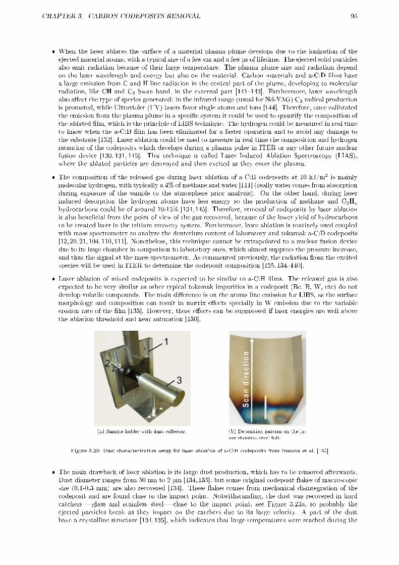
CHAPTER 3. CARBON CODEPOSITS REMOVAL 95
� When the laser ablates the surface of a material plasma plume develops due to the ionization of theejected material atoms, with a typical size of a few cm and a few μs of lifetime. The ejected solid particlesalso emit radiation because of their large temperature. The plasma plume size and radiation dependon the laser wavelength and energy but also on the material. Carbon materials and a-C:D �lms havea large emission from C and H line radiation in the central part of the plume, developing to molecularradiation, like CH and C2 Swan band, in the external part [141�143]. Furthermore, laser wavelengthalso a�ect the type of species generated: in the infrared range (usual for Nd-YAG) C2 radical productionis promoted, while Ultraviolet (UV) lasers favor single atoms and ions [144]. Therefore, once calibratedthe emission from the plasma plume in a speci�c system it could be used to quantify the composition ofthe ablated �lm, which is the principle of LIBS technique. The hydrogen could be measured in real timeto know when the a-C:D �lm has been eliminated for a faster operation and to avoid any damage tothe substrate [132]. Laser ablation could be used to measure in real time the composition and hydrogenretention of the codeposits which develops during a plasma pulse in ITER or any other future nuclearfusion device [130, 131, 145]. This technique is called Laser Induced Ablation Spectroscopy (LIAS),where the ablated particles are destroyed and then excited as they enter the plasma.
� The composition of the released gas during laser ablation of a-C:H codeposits at 10 kJ/m2 is mainlymolecular hydrogen, with typically a 4% of methane and water [111] (really water comes from absorptionduring exposure of the sample to the atmosphere prior analysis). On the other hand, during laserinduced desorption the hydrogen atoms have less energy so the production of methane and C2Hx
hydrocarbons could be of around 10-15% [134,145]. Therefore, removal of codeposits by laser ablationis also bene�cial from the point of view of the gas recovered, because of the lower yield of hydrocarbonsto be treated later in the tritium recovery system. Furthermore, laser ablation is routinely used coupledwith mass spectrometry to analyze the deuterium content of laboratory and tokamak a-C:D codeposits[12, 20, 21, 104, 110, 111]. Nonetheless, this technique cannot be extrapolated to a nuclear fusion devicedue to its huge chamber in comparison to laboratory ones, which almost suppress the pressure increase,and thus the signal at the mass spectrometer. As commented previously, the radiation from the excitedspecies will be used in ITER to determine the codeposit composition [125,134�140].
� Laser ablation of mixed codeposits is expected to be similar to a-C:H �lms. The released gas is alsoexpected to be very similar as other typical tokamak impurities in a codeposit (Be, B, W, etc) do notdevelop volatile compounds. The main di�erence is on the atoms line emission for LIBS, as the surfacemorphology and composition can result in matrix e�ects specially in W emission due to the variableerosion rate of the �lm [133]. However, these e�ects can be suppressed if laser energies are well abovethe ablation threshold and near saturation [130].
(a) Sample holder with dust collector. (b) Deposition pattern on the in-
ner stainless steel foil.
Figure 3.23: Dust characterization setup for laser ablation of a-C:H codeposits from Ivanova et al. [135]
� The main drawback of laser ablation is its large dust production, which has to be removed afterwards.Dust diameter ranges from 50 nm to 2 μm [134,135], but some original codeposit �akes of macroscopicsize (0.1-0.3 mm) are also recovered [134]. These �akes comes from mechanical disintegration of thecodeposit and are found close to the impact point. Notwithstanding, the dust was recovered in hardcatchers �glass and stainless steel� close to the impact point, see Figure 3.23a, so probably theejected particles break as they impact on the catchers due to its large velocity. A part of the dusthave a crystalline structure [134,135], which indicates that large temperatures were reached during the

CHAPTER 3. CARBON CODEPOSITS REMOVAL 96
ablation. Due to these large temperature almost no hydrogen is expected in most part of the dust.Moreover, as few hydrocarbons are detected in the gas (around 4%), dust composition has to be almostall the eroded carbon and other impurity atoms (Be, B, W, etc). However, due to the small size of thedust it cannot be analyzed by usual NRA to con�rm the low H content. In order to remove the produceddust the ejection path of the particles must be determined. Results from solid dust catchers indicatedthat particle ejection seems to follow a cosine distribution with the solid surface [135]. Because of this,a laser integrated with the nozzle of a vacuum cleaner has been proposed to remove by suction theproduced dust [135], but to be e�ective the nozzle has to be very close to the solid surface to reducelosses.
� Apart from dust, some a-C:H �lm is also redeposited in the close vicinity of laser impact, as can beseen in the stainless steel foil recovered after laser ablation in Figure 3.23b. Hydrogen content of these�lms is very low, H/C of 0.02-0.05, lower than the original codeposit H/C 0.09-0.12 [14, 134, 135], andit is not distributed homogeneously, as the �lm further from the laser impact point has more H (2.5times more). Furthermore, this distribution con�rms the origin of the �lm from hydrocarbon radicalswhich develop at the end of the plasma plume. The more H atoms an hydrocarbon radical has, themore stable is, and then the lower sticking coe�cient, see Table 2.5. Hydrocarbon radicals with fewerH atoms will stick to the surface �rst, so the �lm close to the laser impact has lower H content thanthe further one. Nevertheless, most of these redeposited �lms will be eroded again during the laserscanning of the surface, and their low H content will not be an issue.
Few studies have been done about laser ablation removal of carbon codeposits in gas [125, 139]. First, thepressure itself may be bene�cial in a subsequent dust recovery by vacuum cleaner, as the particles are larger(aggregation is enhanced) and they travel shorter distances [146]. Moreover, if the laser is integrated with thenozzle of the vacuum cleaner, thanks to the larger pressure the particles will be captured more e�ciently. Onthe other hand, there are some drawbacks for the use of gas. If a laser in the IR range is used then the ablationdepth decreases with the gas pressure [139], while no e�ect was observed in visible range (532 nm) laser evenat atmospheric pressure [125]. However, if a laser in the UV range is used to ablate diamond-like carbon�lms, the ablation depth also decreases with gas pressure and with the molecular mass of the gas used [146].This e�ect seems to be related to the collisions of the ejected particles with molecules of the ambient gas,decreasing their �ight distance. The larger the molecular mass the more particles cannot leave the cratermade by the laser, and are then eroded in subsequent laser pulses [146]. This will reduce the dust production,but also the laser ablation depth. If a reactive atmosphere is used, the a-C:H �lm redeposition will be mostprobably hampered, and the size of the hot ejected particles could be reduced. The a-C:H redeposition hasbeen con�rmed to be suppressed in oxygen and air during ablation of diamond-like �lms, but in hydrogen,helium and nitrogen the redeposition is more obvious than in vacuum [146]. The last e�ect is probably due tothe enhanced condensation of the carbon radical in gas, as in vacuum the carbon radicals can travel further.Notwithstanding, this last experiment was done on diamond-like carbon, much more chemical resistant thana-C:H, whose reactivity towards hydrogen and nitrogen is larger.
3.3.2 Experimental
All experiments were conducted in the setup depicted in Figure 3.24 in collaboration with the IPPLM institutefrom Warsaw, Poland, very similar to previous experiments [132�134, 140]. The sample used was a ALT-IIlimiter graphite tile from TEXTOR tokamak over a moving stage, with a hard type a-C:D codeposit on top,40-60 µm thick, with a D/C ratio of 0.09-0.12. The laser is a Nd:YAG, Q-switched pulsed laser system, whichprovided pulses with 3.5 ns duration, 0.5 J energy at the fundamental wavelength of 1064 nm. It is focusedby means of a series of lens to a spot of 3 mm diameter, resulting in an energy density of 70 kJ/m2, muchlarger than the ablation threshold for both graphite and a-C:D, 2.5-10 kJ/m2, and near ablation saturation.At this energy density the surface morphology e�ect is much reduced [130]. A fast CCD camera with aminimum frame time of 10 µs was used for a direct observation of the hot ejected particles �thanks to theirradiation emission� and the plasma plume for each gas. The camera was triggered by the laser system,but the delay between the laser pulse and the start of the CCD acquisition was varied from from 10 us toseveral ms. The most adequate delay time to observe particles release was at 40 µs from laser-producedions detection at the Ion Energy Analyzer (IEA). The image may be integrated from 10 µs to 1 ms. Theemission spectra of the plasma plume was analyzed by Optical Emission Spectroscopy (OES) in the LIBS(Laser Induced Breakdown Spectroscopy) approach. It was collected at 3 mm from the target in a 3 mmdiameter region with an optical �ber connected to a Mechelle 5000 spectrometer with IStar ICCD througha 50 µm entrance slit. The wavelength range was from 400 to 970 nm, with an accuracy of ±0.05 nm and aspectral resolution (λ/Δλ) of 4000. A delay of 75 ns with respect to the laser pulse and an integration timeof 500 ns were applied. The chamber was pump down by a di�usion pump in series with a rough pump until
CHAPTER 3. CARBON CODEPOSITS REMOVAL 97
Figure 3.24: Experimental setup for dust production studies during laser ablation of tokamak a-C:D codeposits at IPPLM,Warsaw (Poland). For dust collection experiments two aerogel collectors were placed at 2 cm from the laser impact point,usually tilted to an angle of 25° with respect to sample.
∼5·10-3 Pa prior the experiments. Two kinds of experiments were done: the characterization by fast cameraand OES of the plasma plume and the particle ejection in di�erent gases; and the capture and compositionalanalysis of the ejected particles in aerogel collectors.
3.3.2.1 Plasma plume and dust ejection in gas
First, laser ablation of two kinds of laboratory a-C:D codeposits were done in order to test the OES emissionof carbon and deuterium lines in samples with a controlled composition: 3 µm thick, hard a-C:D overgraphite; and 1 µm thick, soft a-C:D over silicon. The samples were fabricated in the Institute of ElectronicMaterials Technology at Warsaw, Poland. As the samples are not calibrated the LIBS spectra can only becompared by means of ratios, as absolute quanti�cation cannot be done. The ratio used will be the C+(426.65nm)/Dα(656.10 nm) lines �C+/Dα�, although the minor C+ lines at 657.8 and 658.29 nm will also be shownin the graphs to compare with Dα due to their proximity. C+ signal was also used to normalize intensitybetween experiments as it can give an estimate of the eroded �lm thickness. It is necessary to note that theionization per photon ratio of each species, S/XB, is highly dependent of the plasma conditions, temperatureand density, so the C+/Dα ratio will not be proportional with the real D/C ratio of the codeposit.
As a second step, laser ablation of a-C:D codeposits from TEXTOR tokamak were investigated in di�erentreactive �N2, H2 and O2� and inert �He� gases at several pressures: 10, 100 and 50,000 Pa, and theirresults were compared with laser ablation in vacuum. High purity gases were used, > 99.999%. The connectionof the vacuum chamber to the pumps were cut and then the gas was leaked in until the desired pressure.The main aim of these series of experiments was the separation of physical gas e�ects: larger particles byaggregation and with shorter ejection distances [146]; from chemical gas e�ects: particle surface erosionand deuterium elimination due to the large temperature of the ejected particles. Particles velocity can beestimated by the length of their recorded lines in the fast CCD camera, while its size coupled with itstemperature could be qualitatively compared from the thickness of these lines, only at some speci�c caseswhere both properties can be separated. Only the particles in the plane of observation of the camera, i.e. inthe focus range or depth of �eld (around 2 mm), will be observed, so there will be a small, unknown variationin the angle of the particle with the camera plane depending on the acquisition time. This error will bepropagated to the observed distance traveled by the particle during the integration time of the camera, andthen to the calculated velocity. In order to reduce this error, more than 10 lines were measured to obtaina statistical error to include this. Plasma plume size and shape are also investigated by fast CCD cameraimaging to obtain an estimation of particle erosion by excited molecules and atoms in the plasma plume.

CHAPTER 3. CARBON CODEPOSITS REMOVAL 98
3.3.2.2 Dust collection in aerogel
Aerogel collectors have been used previously for dust analysis in tokamaks [147,148]. They consist in vacuum-compatible silica gel of very low density. The main advantage over other collector types as stainless steel isthat the incoming particles su�er almost not damage when impacting the aerogel, moreover, the particlesare trapped into it. Therefore, they allow a more realistic particle size distribution calculation, and eventheir impact velocity can be estimated based on their penetration length [147]. Furthermore, as they aretrapped inside the aerogel they can be easily transported and analyzed by di�erent methods without any riskof further contamination. The aerogel collectors were situated at 2 centimeters in front of the laser impactpoint, see Figure 3.24, to catch as many particles as possible avoiding any damage from the plasma plume.In fact, during preliminary experiments a safe distance of 0.5 cm was determined. The experiments wereconducted in vacuum and at 100 and 1000 Pa of O2 to test if chemical erosion and pressure can play a roleduring laser ablation.
In order to compare the particle characteristics in both vacuum and O2 the collected dust were analyzedby speci�c aerogel techniques at RIT. First, a Micro-Nuclear Reaction Analysis (μ-NRA) was performed. Cconcentration was measured by 12C(3He,p0)14N nuclear reaction, and D with D(3He, p)4He nuclear reaction.The beam with a current of ∼200 pA was demagni�ed into a rectangular spot with side about 20 μm. Duringanalysis the spot was moved over each particle to collect their C and D proton spectra. SIMNRA [117]simulation software was used to evaluate the D/C ratio for each particle. After the μ-NRA analysis the sameparticles were investigated with Scanning Electron Microscopy (SEM) to obtain their size, shape, surfacemorphology, and evaluate impact damage to the aerogel surface to estimate their impact speed. Finallyoptical microscopy was used to count the trapped particles as buried ones are not easily accessible by SEM.
3.3.3 Results and discussion
3.3.3.1 Plasma plume, surface crater and dust ejection in gas
Plasma plume optical characterization
(a) 3 pulses at same location on 3 µm hard a-C:D/Graphite. (b) 3 pulses at di�erent locations on 1 µm soft a-C:D/Si.
Figure 3.25: Optical Emission Spectra (OES) during laser ablation of a-C:D laboratory samples in vacuum.
Part of the results presented in this point have been recently published [127], but a more detailed studywill be given here. In order to compare the D elimination rate during laser ablation in di�erent gases the ratioof the areas of the C+/Dα peaks measured by OES will be used. Although the ratio has not been quanti�edbecause of their complexity �di�erent codeposits means di�erent and unknown laser plumes temperatureand density� it can be used for comparison. To test the validity of LIBS two laboratory a-C:D �lms withdi�erent D/C ratio, ∼0.4 for hard and ∼1 for soft, have been ablated by laser. In Figure 3.25 the main C+
and Dα lines are shown. C+ lines at 657.8 and 658.29 nm are also shown as they are su�ciently intenseand close to Dα to be used to con�rm visually any C+/Dα variation. As it can be seen in Figure 3.25 andTable 3.6 the C+/Dα ratio is about 2-3 times larger in hard a-C:D �lms than in soft ones. Furthermore, itsvalue is approximately constant for di�erent locations along the sample, even for the soft a-C:D �lm whereonly a 20% variation is seen in spite of being removed in just one laser pulse. These results demonstrate thegood repeatability of LIBS for its use to compare the D elimination rate during laser ablation in di�erentgases using the ratio C+/Dα measured by OES. On the other hand, the large laser D elimination rate can bededuced from Table 3.6. In hard a-C:D �lm the C+/Dα ratio increases quickly with the number of pulses,
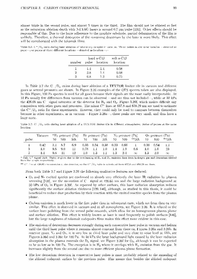
CHAPTER 3. CARBON CODEPOSITS REMOVAL 99
almost triple in the second pulse, and almost 5 times in the third. The �lm should not be ablated so fastas the saturation ablation depth with Nd:YAG lasers is around 0.7 μm/pulse [131]. Other e�ects should beresponsible of this. Due to the large adherence to the graphite substrate, partial delamination of the �lm isunlikely. Therefore, a thermal desorption of the remaining deuterium by the laser is more likely. This e�ectwill be corroborated with the tokamak �lms.
Table 3.6: C+/Dα ratio during laser ablation of laboratory samples in vacuum. Three pulses at the same location �denoted aspulse�, or pulses at three di�erent locations �denoted as location�.
hard a-C:D soft a-C:Dnumber pulse location location
1 1.4 1.4 0.582 3.8 1.4 0.883 6.8 1.3 0.75
In Table 3.7 the C+/Dα ratios during laser ablation of a TEXTOR limiter tile in vacuum and di�erentgases at several pressures are shown. In Figure 3.26 examples of the OES spectra taken are also displayed.In this Figure, 100 Pa spectra is used for all gases because their signals are the most easily interpretable. At10 Pa usually few di�erences from vacuum can be observed �and are thus not included�, while at 50 kPathe 426.65 nm C+ signal saturates at the detector for N2 and O2, Figure 3.26f, which makes di�cult anycomparison with other gases and pressures. The minor C+ lines at 657.8 and 658.29 nm are used to estimatethe C+/Dα ratio for these experiments. However, they could only be used to compare between themselvesbecause in other experiments, as in vacuum �Figure 3.26a�, these peaks are very small, and thus have alarge error.
Table 3.7: C+/Dα ratio during laser ablation of a TEXTOR limiter tile in di�erent atmospheres. Series of pulses at the samelocation
Vacuum *H2 pressure (Pa) He pressure (Pa) N2 pressure (Pa) O2 pressure (Pa)pulse 10 100 50k 10 100 50k 10 100 **50k 10 100 **50k
1 0.42 5.1 5.7 6.9 0.33 0.34 0.38 0.33 0.66 1 0.36 0.54 1.13 1.0 9.5 9.0 11 0.78 1.1 1.0 1.1 1.9 6.6 1.0 1.6 235 1.4 9.8 11 12 1.0 1.3 1.1 1.3 2.4 ∞ 1.3 2.0 ∞
* Only C+ signal (Arb. Units) is given due to the overlapping of Hα and Dα emission lines from hydrogen gas and deuterium ejectedfrom the sample respectively.
** C+ line at 426.65 nm saturates at the detector, so the C+/Dα ratio is calculated from 657.8 and 658.29 nm lines.
From both Table 3.7 and Figure 3.26 the following qualitative features are deduced:
� O2 and N2 excited species are con�rmed to absorb very e�ciently the laser IR radiation by plasmascreening [139], see the saturation of C+ signal at 426.65 nm and the large radiation background at50 kPa of O2 in Figure 3.26f. As reported by other authors, this laser radiation absorption reducessigni�cantly the surface ablation thickness [139, 146], although, as studied in this thesis, it could bebene�cial to reduce dust production by their reaction with the excited reactive species from the plasmaplume.
� Carbon emission is much lower in the �rst pulse than in subsequent ones, which are from then on verysimilar. This e�ect is observed in vacuum and at all atmospheres, see Figure 3.26. It is related to thesurface laser polishing from the second pulse onwards, which allow for an homogeneous plasma plumeand surface ablation. This e�ect is widely known as laser is used frequently to polish surfaces [146],but the large roughness of tokamak codeposits �lms makes this e�ect more evident in this case.
� The emission of deuterium decreases strongly during each consecutive laser pulse in vacuum and heliumuntil the third laser pulse where it remains almost constant from there on, Figures 3.26a and 3.26b. Inreactive gases, N2 and O2, it is very low at third laser pulse and very close to noise level at �fth, seeFigures 3.26d and 3.26e for 100 Pa. At 50 kPa the large background light caused by the laser radiationabsorption in the plasma conceals the Dα signal, see Figure 3.26f for O2, although it can be expectedto be as low as in 100 Pa. The exception is in H2 where it overlaps with Hα emission from the gas. Itincreases slightly from the second one due to more e�cient plasma plume formation.
� The low deuterium detection in consecutive laser pulses is most probably related to the annealing ofthe ablated codeposit surface by the previous pulse. This means that besides the ablated codeposit

CHAPTER 3. CARBON CODEPOSITS REMOVAL 100
thickness, at least the same quantity is heated up until 400-600 °C or more to allow hydrogen to bereleased so fast [11,12]. In vacuum around 0.5-0.7 µm is ablated for each laser pulse at our conditions,which points that more than these thickness is additionally annealed by each laser pulse. In reactivegases, N2 and O2, codeposit annealing is enhanced by reactions at the large temperatures achieved asfew D is seen from third/�fth laser pulse. In the case of O2 this decrease is most probably due to aprocess similar to thermo-oxidation, as in section 3.2, but in N2 the D signal decrease is more probablebecause of the formation of a-C:N �lms on the laser impact (and the ablation of that �lm in subsequentlaser pulses), as the reaction of the nitrogen species with carbon �lms is not so favored as O2. Forlaser ablation in O2, this would also mean that the expected decrease in ablation erosion rate due toIR laser absorption could be partially compensated by codeposit erosion by thermo-oxidation. Anotherimportant consequence of this annealing is that only the dust produced in the �rst, and perhaps second,laser pulses will contain some hydrogen isotopes retained. Moreover, the dust produced in the �rst pulsewill contain some relatively large particles from mechanical disintegration of the codeposit [134], andthey will have almost the original hydrogen isotope content. Therefore, the study of the dust producedin the �rst laser pulse is paramount, which will be investigated in the following section with the fastcamera, although due to their large size they are expected to travel shorter distances [134].
� Both lower deuterium emission and larger carbon emission cause the increase of the C+/Dα ratio withthe number of laser pulses, see Table 3.7, specially from the �rst pulse due to the previously commentedlaser polishing. This increase is evident in reactive gases, but at 50 kPa the huge values obtained are anartifact, as they are caused by the plasma laser radiation absorption which conceals the, otherwise small,Dα signal. Furthermore, it can be deduced comparing C+/Dα ratio in He and vacuum experiments thatgas pressure slightly reduces the D elimination rate, see Table 3.7.
Gaseous products from the reaction of carbon and deuterium from the codeposit with the surroundingatmosphere could also be detected in the plasma plume. However, the OES spectra is taken very close tothe surface, 3 mm, when most of the molecular products develop at the external part of the plasma plume�specially from nitrogen [142,149]�, and appear at longer times than used in the experiments of this thesis�integrated from 75 until 575 ns� ,when for example CN appears at 1 µs [142,143]. As will be seen in thefollowing point, the typical size of the plasma plume at 100 Pa is in the order of centimeters, so a large partof the molecular products will not be detected. So close to the surface and at so earlier times mostly singlyionized ions and excited neutrals will be found [142, 143], which is ideal for characterization of remaining Dcontent in the �lm by LIBS, the main objective of this thesis. Although the OES spectra was optimized forthe detection of deuterium some species from the reaction with the surrounding atmosphere were found:
� In oxygen plasmas CO+ emission at 427.43 nm, the comet-tail system [150], has been found, seeFigure 3.26e. At 50 kPa CO is not detected mostly because of saturation of the C+ signal at 426.65nm, Figure 3.26f. As will be explained in the following point, this quick and near-surface formationof CO suppress the formation of carbon codeposits surrounding the laser impact point that have beendetected in vacuum and other gases by other authors [134, 135]. Furthermore, a decrease in the meandust size in oxygen will also be expected. Other systems have not been found, as most are in the UVrange (< 400 nm), which cannot be detected in this experimental setup. Therefore, the formation ofCO at other locations and times during the plasma plume is not ruled out.
� No evidence of D2O or OD/OD+ systems have been found. Notwithstanding, H2O emit mostly inIR �at >900 nm�, and OH/OH+in the UV �at <400 nm� [150] which cannot be detected in ourspectrometer. Water has been detected to be produced in low quantities, <4%, during laser ablationof tokamak codeposits by other authors [111], so the formation of water molecules is expected to occurat longer times and at the external part of the plasma plume.
� In nitrogen plasmas no evidence of CN is detected in its red system. Although it is possible thatsome CN develops and emit in the UV system, as other authors detect CN development only at largertimes and distance from the laser impact point [142, 143,149]. ND/ND+ and ND2 systems are neitherdetected. ND/ND+ because they emit mostly in UV, but even then their yield is expected to be verylow �nitrogen molecule is very stable� and they will develop in the external part of the plasma plume.ND2 will require longer to develop due to the large number of reactions needed to form it.
� Other species could also develop in small concentrations in H2, He or vacuum plasmas , like CH/CD,CH+/CD+, low-hydrogen hydrocarbons, C2 Swan bands, etc. Only CH/CD+ at 422.5 nm seems to bedetected in very small quantities in H2 and vacuum experiments at the �rst pulse, when D quantity ismuch larger. No other systems were detected, as they also need longer times to develop and they willappear in the external part of the plasma plume [142,144,149,151]. Nonetheless, all these species have

CHAPTER 3. CARBON CODEPOSITS REMOVAL 101
(a) Vacuum. (b) He at 100 Pa.
(c) H2 at 100 Pa. (d) N2 at 100 Pa.
(e) O2 at 100 Pa. (f) O2 at 50 kPa
Figure 3.26: Optical Emission Spectra (OES) during laser ablation of a TEXTOR limiter tile in di�erent atmospheres. Seriesof pulses at the same location.

CHAPTER 3. CARBON CODEPOSITS REMOVAL 102
to be produced, as hydrocarbon molecules have been previously detected by mass spectrometry duringlaser ablation of hydrocarbon �lms, although in small quantities [111]. C2 radical is also expected todevelop as it is also promoted at larger pressures [144,151], even in O2 [151]. Furthermore, it seems tobe promoted by IR lasers like Nd-YAG [144].
Surface crater by ablation
Due to the large surface roughness of the TEXTOR tokamak codeposit, in the order of µm, and the few pulsesdone for each experiment, only 5, the ablation rate could not be measured as the pro�lometry measurementerrors were too large. Undoubtedly, the ablation rate seems to be much lower for larger pressures, specially at50 kPa, where almost no di�erences with un-irradiated codeposit were found. The ablation rate in vacuum wasdetermined in preparation experiments (with a larger number of laser pulses) to be around 0.5-0.7 µm/pulse,therefore a crater of 2.5-3.5 µm could be expected in the experiments done here. Ablation rates obtainedby other authors with UV lasers will allow the discrimination of the purely physical and chemical e�ects.An ArF laser was used to ablate diamond-like carbon �lms in the same gases as this thesis [146], but atatmospheric pressure. The results were an ablation rate with respect to vacuum of approximately half in He,O2 and H2 and a third in N2, which suggests a small UV absorption by N2 plasma plume. This e�ect seemsto be caused by the decrease in the �ight distance of the produced dust, which stays at the crater and is theneroded in subsequent pulses [146]. However, tokamak carbon codeposits are very porous and more reactivetowards oxygen and nitrogen, so larger ablation rates than diamond-like carbon �lms could be expected inthese gases. To summarize, a reduction factor slightly lower than 2-3 due to pure physical laser ablation willbe expected in our experiments at 50 kPa, close to the atmospheric pressure of that work, decreasing quicklywith pressure. Furthermore, a decrease in dust production is also expected.
On the other hand, the results obtained by other authors with IR laser ablation (Nd:YAG) of tokamakcodeposits in di�erent pressures of IR absorbing gases �Ar� [139] allow for an estimation of the ablationrate in our experiments for N2 and O2 if surface chemical erosion aided by laser heating is low. In Ar a factor2 reduction is detected when increasing pressure from 50 to 500 Pa, but a larger reduction factor of 8 is seenwhen increasing from 50 to 5000 Pa. This probable exponential ablation rate decrease is related to a muchmore e�cient IR laser radiation absorption at larger pressures. Therefore, if the ablation rate at 10 Pa isconsidered to be similar to vacuum, as suggest the analogous C+/Dα, see Table 3.7. Comparing 10 Pa and100 Pa an reduction factor slightly larger than 2 could be expected, but increasing the pressure to 50 kPacould lead to reduction factors of 16 or more, completely unacceptable unless if dust production is suppressedor much reduced.
(a) Vacuum. (b) He at 10 Pa, 100 Pa and 50 kPa. (c) H2 at 10 Pa, 100 Pa and 50 kPa.
(d) N2 at 10 Pa, 100 Pa and 50 kPa. (e) O2 at 10 Pa, 100 Pa and 50 kPa.
Figure 3.27: Pictures of surface craters left by laser ablation in various atmospheres.
Reports from other authors when an ArF laser was used to ablate diamond-like carbon �lms indicate theformation of amorphous carbon �lm of similar height than the ablated �lms at the periphery of the crater inHe, H2 and N2 at atmospheric pressure, when in oxygen and air they are not produced [146]. In vacuum thea-C:H �lm is neither detected, but probably because thinner and more expanded �lms are produced due tothe longer distances the evaporated carbon species can travel in vacuum with respect to a gas environmentat atmospheric pressure. Oppositely, in hydrogenated carbon codeposits from tokamaks the formation ofa-C:H �lms around the crater is more evident as reported by other authors [134, 135], due to the generationof hydrocarbon radicals. In the experiments of this thesis, the a-C:D �lm redeposition around the crater wasnot an initial objective, so the number of laser pulses over the same point was too low to develop a thick�lm. Furthermore, only low-quality pictures of the tokamak sample were taken during the process. The �lm,

CHAPTER 3. CARBON CODEPOSITS REMOVAL 103
however, can be glimpsed at the pictures in Figure 3.27, see for example the brownish �lm around the craterleft by laser ablation in vacuum, Figure 3.27a. These �lms around crater are also glimpsed at 10 Pa for allgases, sub�gures in Figure 3.27, suggesting the low in�uence of working at that pressure as OES spectraindicated in the previous point. In agreement with other authors [146], at He and H2 the �lms are becomingmore obvious to the naked eye and closer to the crater periphery as pressure is increased, Figures 3.27band 3.27c respectively. In N2 the same e�ect is observed, Figure 3.27e, but the �lm is darker, suggestingthe formation of an a-C:H:N �lm [146], and in agreement with the possible formation of a-C:N on the laserimpact as seen in the previous point. In O2 a di�erent pattern is detected when increasing pressure, as thecrater borders seems to be eroded, see grey color in Figure 3.27e. Therefore, oxygen seems to be the bestgas in order to suppress the formation of carbon codeposits surrounding the crater during laser ablation, asit has been previously reported by other authors [146], as even it seems to erode the surrounding surface.Consequently, the next step is to characterize the plasma plume size for the di�erent atmospheres and itse�ect in the dust ejection pattern to con�rm the better results in oxygen.
Plasma plume shape and particles ejection pattern characterization
Plasma plume shape and particles ejection during laser ablation of a tokamak codeposit were recorded witha fast camera. The integration time could be varied to have an estimation of particles velocity at short times�10 µs� , measuring the length of the recorded lines left by the particles path, or to observe the plasmaplume shape �50-100 µs�. At larger pressures of IR absorbent gases, N2 and O2, even at short times of 10µs the background light was excessive and the detector saturates along the most part of the image.
The �rst issue observed is the con�rmation of the ejection of larger particles in the �rst laser pulsecompared to the subsequent discharges. The comparison is evident during laser ablation in vacuum, a fewthicker and more radiant lines can be seen in the �rst pulse which are absent in the third at an integratedtime of 100 µs, Figures 3.28a and 3.28c respectively. Moreover, at second and �fth pulses �both recordedduring 10 µs� the lines, i.e. particles, have a similar size and velocity, i.e. lines length and distribution,compare Figures 3.28b and 3.28d, which con�rms that in the �rst pulse larger particles are ejected. At thesame �gures the ejection pattern is con�rmed to be conical and centered at the laser impact point. Mostparticles are ejected close to the cone axis, and moreover, they seem to be larger and hotter, i.e. thicker andmore radiant lines, than at the borders where they have a less de�ned shape (as they are also going out offocus range). This last point is specially evident in Figure 3.28c, third pulse at 100 µs integrated time.
The di�erences in the developed plasma plume for the di�erent studied gases at 100 Pa are shown inFigure 3.28. As it can be deduced, the lighter the atoms, the larger and the further from the laser impactpoint the plasma plume is detected: compare H2 in Figure 3.28e, whose plasma plume is out of the scale(>3.4 cm); with He plasma plume which starts at 1.5-1.7 cm in Figure 3.28f; or with N2 and O2 whose plasmaplume develops from laser impact point until 2.5-3 cm, Figures 3.28g and 3.28h respectively. Additionally,in both last Figures the larger IR laser energy absorbed by oxygen can be deduced comparing the brightnessof the plasma plume and dust lines. A value of 100 Pa has been chosen to compare plasma plumes becauseat 10 Pa the developed plasma plume is small, and at 50 kPa is too intense for N2 and O2 due to theirIR laser radiation absorption and are therefore di�cult to interpret. This di�erence can easily be observedwhen following He plasma plume evolution at di�erent pressures �Figures 3.29a, 3.28f and 3.29b�, and O2
plasma one �Figures 3.29d, 3.28h and 3.29e.Particles ejection also changes because of gas pressure as expected [146]. Unfortunately, due to the di�erent
integration times, particles ejection during the �rst pulse in gas and in vacuum cannot easily be compared.In gas short integration times (10 µs) were needed because of large plasma plume light emission, while invacuum at these short times in the �rst laser pulse no particles ejection was detected, probably becauseof a di�erent physical ablation of the surface which makes the particle ejection a little slower. Integratingthe �rst pulse during 100 µs �Figure 3.28a� and during 10 µs at subsequent laser pulses �Figures 3.28band 3.28d� the particle ejection was recorded with no problem. Notwithstanding, in helium at 50 kPaduring the �rst laser pulse large particles are also detected as in vacuum, Figure 3.29c. In oxygen at 50kPa �Figure 3.29f� particles ejection is di�cult to follow but it seems consist on small particles. If thequantity of released particles is qualitatively compared between vacuum �Figure 3.28d� and an increasinggas pressure as helium, which only has a physical e�ect, a progressive lower number of particles ejection seemsto be ejected: �gures 3.29a, 3.28f and 3.29b. However, only the region close to the laser impact point shouldbe considered, as the fastest particles in the left side of the picture can be observed in helium experimentsbecause they emit more radiation due to heating by the developed plasma. At 10 Pa �Figure 3.29a� almostno di�erences can be observed with respect to vacuum; at 100 Pa �Figure 3.28f� a slightly lower particleejection can be inferred; while at 50 kPa �Figure 3.29b� more smaller (de�ned by their brightness) particlesand less larger ones are detected, although this could be due to contrast with the plasma plume. Therefore,the predicted e�ect of lower dust ejection with large pressure cannot be con�rmed [146]. Moreover, as seen
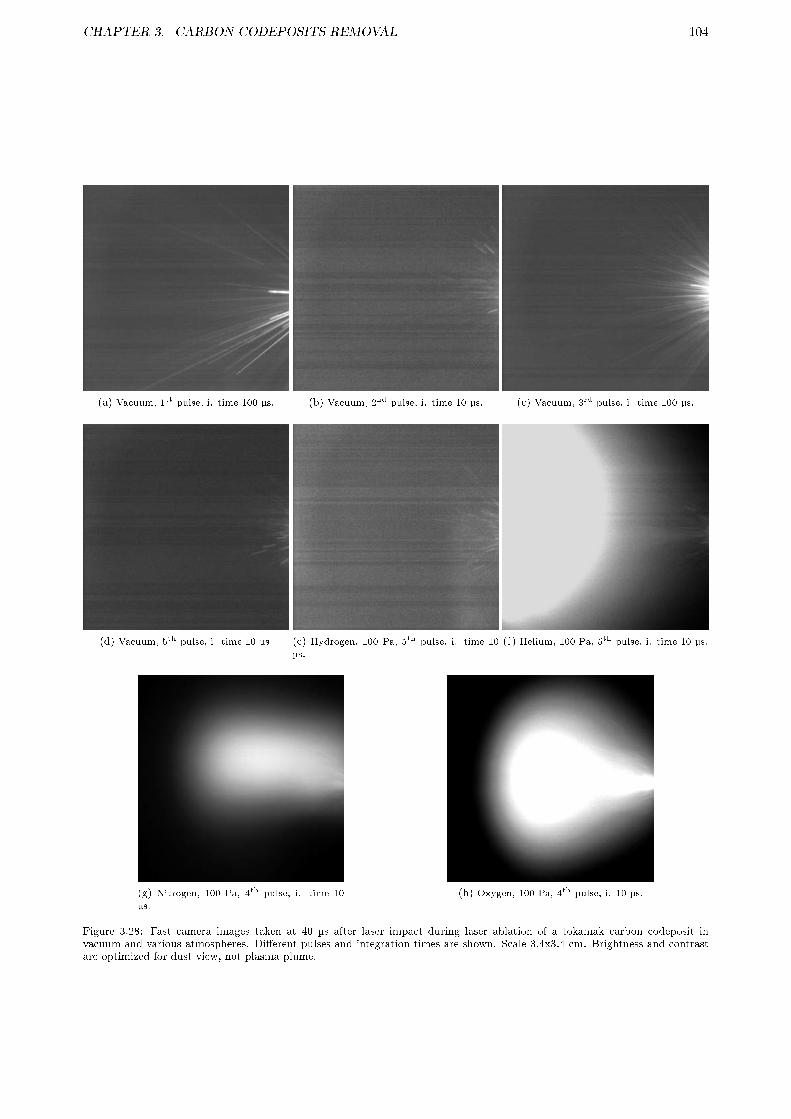
CHAPTER 3. CARBON CODEPOSITS REMOVAL 104
(a) Vacuum, 1st pulse, i. time 100 µs. (b) Vacuum, 2nd pulse, i. time 10 µs. (c) Vacuum, 3rd pulse, i. time 100 µs.
(d) Vacuum, 5th pulse, i. time 10 µs. (e) Hydrogen, 100 Pa, 5th pulse, i. time 10
µs.
(f) Helium, 100 Pa, 5th pulse, i. time 10 µs.
(g) Nitrogen, 100 Pa, 4th pulse, i. time 10
µs.
(h) Oxygen, 100 Pa, 4th pulse, i. 10 µs.
Figure 3.28: Fast camera images taken at 40 µs after laser impact during laser ablation of a tokamak carbon codeposit invacuum and various atmospheres. Di�erent pulses and integration times are shown. Scale 3.4x3.4 cm. Brightness and contrastare optimized for dust view, not plasma plume.

CHAPTER 3. CARBON CODEPOSITS REMOVAL 105
previously, the ablated �lm thickness in gas is lower than in vacuum, so less dust will be generated per shot.On the other hand, the velocity of the ejected particles can also be estimated with the length of the
lines left by their travel, with the uncertainty of their angle direction respect to the image plane reducedby averaging more than 10 lines. Only the particles in the region close to the laser impact point has beenmeasured to assure a similar particle size distribution (fastest particles usually have a very di�erent size,and they are di�cult to measure in vacuum). In vacuum a mean path of 0.25±0.05 cm is measured, whichcorresponds to a velocity of 250±50 m/s. In helium it decreases at 10 Pa to 190±40 m/s, to 170±40 m/s at100 Pa; while at 50 kPa their velocity is more reduced: 135±30 m/s. As can be expected from friction withgas molecules, ejected particles velocity seems to be lower, and thus dust will be deposited closer to the laserimpact point than in vacuum.
(a) Helium, 10 Pa, 3rd pulse, i. time 10 µs. (b) Helium, 50 kPa, 5th pulse, i. time 10 µs. (c) Helium, 50 kPa, 1st pulse, i. time 10 µs.
(d) Oxygen, 4 Pa, 4th pulse, i. time 10 µs. (e) Oxygen, 50 kPa, 4th pulse, i. time 10 µs. (f) Oxygen, 50 kPa, 1st pulse, i. time 10 µs.
Figure 3.29: Fast camera images at taken at 40 µs after laser impact during laser ablation of a tokamak carbon codeposit indi�erent atmospheres at various pressures, and from �rst laser pulse at 50 kPa in He and O2. Scale 3.4x3.4 cm. Brightness andcontrast are optimized for dust view, not plasma plume.
The in�uence of a reactive gas on the ejected particles is expected to be detected in the fast cameraimages as changes in the thickness of their lines. At 100 Pa no special in�uence can be seen with theexception of a larger brightness, related to the plasma plume in oxygen, Figure 3.28h, which will indicate alarger temperature. At 50 kPa in hydrogen no special change is observed, but at nitrogen and oxygen dueto the large IR laser absorption by the plasma the images are di�cult to interpret, see Figure 3.29e for O2.Nevertheless, the emitted dust seems to be smaller in these reactive atmospheres than in vacuum.
Ejected dust characterization
Most of the results have been already published [126], but a more details will be given here. For dust analysisin a reactive gas only experiments in vacuum and oxygen have been done due to limitation in the numberof experiments. The detection of CO+ emission and the smaller size of the emitted dust recoded by thefast camera during experiments in oxygen have been determinant for this choice. Furthermore, it could beapplied to a possible laser ablation removal of W/Be codeposits in ITER in an oxygen atmosphere. In thiscase the volatile WO3 will be developed from the reaction with the ejected particles decreasing dust size.

CHAPTER 3. CARBON CODEPOSITS REMOVAL 106
(a) Vacuum, 25° tilted, 5 pulses done, i. time100 µs.
(b) Vacuum, parallel, 1st pulse, i. time 100
µs.
(c) Oxygen, 100 Pa, 25° tilted, 5 pulses done,i. time 100 µs.
(d) Oxygen, 100 Pa, 25° tilted, 5 pulses done,i. time 1 ms.
(e) Oxygen, 1 kPa, 25° tilted, 5 pulses done,
i. time 100 µs.
(f) Oxygen, 1 kPa, 25° tilted, 5 pulses done,
i. time 1 ms.
Figure 3.30: Fast camera images with an aerogel dust collector at 2 cm taken at 40 µs after laser impact during laser ablationof a tokamak carbon codeposit in vacuum and O2. Brightness and contrast are optimized for dust view, not plasma plume.
In order to detect the impact of the ejected particles into the aerogel collectors the integration and trig-gering time were increased signi�cantly until the ms range. It was observed that particles release phenomenaduring laser ablation was sustained along a range of several ms with no in�uence of gas pressure. As pre-viously commented, the presence of O2 caused a decrease of particles velocity, and their emitted light waslarger, suggesting their reaction with oxygen. The di�erent images taken during laser ablation for the captureof part of the emitted particles can be seen in Figure 3.30. In vacuum, Figures 3.30a and 3.30b, it can beobserved how the particles impact on the aerogel, brighter than the stainless steel surrounding it, leading toan intense light emission, specially evident in parallel view. At 100 Pa of O2 a larger aerogel temperaturedue to heating by the plasma plume can be detected, Figures 3.30c and 3.30d. In the last image, taken at1 ms of integration time, the impact of some particles on the aerogel and the backscattering of others areobserved. At 1 kPa of O2 the same e�ects, but stronger, are seen, Figures 3.30e and 3.30f. No damage tothe aerogel was detected after any experiment. In the image taken at 1 ms, Figure 3.30f, it is evident thatthe particles are emitting more light, which con�rms their partial thermo-oxidation with the O2 atmosphere.Furthermore, the curvature of their lines when backscattering indicates collisions with other particles, andalso indicates a large pressure in the central region of the plume because of the presence of the collectorlimiting its expansion.
Collected dust particles captured after 10 laser pulses in vacuum were analyzed by optical microscopy andSEM. As the aerogel is transparent to the visible light it was possible to observe even the buried particlesby optical microscope. SEM images of the dust particles are shown in Figure 3.31. By an EDX analyzercoupled to the SEM it was con�rmed that the particles consist mainly of carbon. Particle impacts on theaerogel are seen as dark spots in Figure 3.31a. All dust particles were really rectangular �akes in the rangeof a few microns length and wide. Some dust particles, as in Figure 3.31b, were partially buried in crosssection, so it was possible to determine their thickness, and it resulted to be around 1.5 μm. Mean particlesimpact velocity, calculated by means of the penetration depth of buried particles, as in Figure 3.31c, was
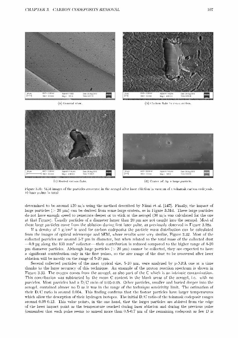
CHAPTER 3. CARBON CODEPOSITS REMOVAL 107
(a) General view. (b) Carbon �ake in cross section.
(c) Buried carbon �ake. (d) Crater left by a large particle.
Figure 3.31: SEM images of the particles recovered in the aerogel after laser ablation in vacuum of a tokamak carbon codeposit.10 laser pulses in total
determined to be around 120 m/s using the method described by Niimi et al. [147]. Finally, the impact oflarge particles (> 20 μm) can be derived from some large craters, as in Figure 3.31d. These large particlesdo not have enough speed to penetrate deeper or to stick at the aerogel (30 m/s was calculated for the oneat that Figure). Usually particles of a diameter larger than 20 μm are not caught into the aerogel. Most ofthese large particles come from the ablation during �rst laser pulse, as previously observed in Figure 3.28a.
If a density of 1 g/cm3 is used for carbon codeposits the particle mass distribution can be calculatedfrom the images of optical microscope and SEM, whose results were very similar, Figure 3.32. Most of thecollected particles are around 5-7 µm in diameter, but when related to the total mass of the collected dust�0.9 µg along the 150 mm2 collector� their contribution is reduced compared to the higher range of 8-20µm diameter particles. Although large particles (> 20 μm) cannot be collected, they are expected to havea signi�cant contribution only in the �rst pulses, so the size range of the dust to be recovered after laserablation will be mostly on the range of 5-20 µm.
Several collected particles of the most typical size, 5-10 µm, were analyzed by μ-NRA one at a timethanks to the large accuracy of this technique. An example of the proton reaction spectrum is shown inFigure 3.33. The oxygen comes from the aerogel, as also part of the C which is an intrinsic contamination.This contribution was subtracted by the mean C content in the blank areas of the aerogel, i.e. with noparticles. Most particles had a D/C ratio of 0.05-0.08. Other particles, smaller and buried deeper into theaerogel, contained almost no D as it was in the range of the technique sensitivity limit. The estimation oftheir D/C ratio is around 0.004. This �nding con�rms that the fastest particles have larger temperatureswhich allow the desorption of their hydrogen isotopes. The initial D/C ratio of the tokamak codeposit rangesaround 0.09-0.12. This value points, in the one hand, that the larger particles are ablated from the edgeof the laser impact point as the temperature reached during laser ablation and during the previous pulse(remember that each pulse seems to anneal more than 0.5-0.7 µm of the remaining codeposit as few D is

CHAPTER 3. CARBON CODEPOSITS REMOVAL 108
detected from �rst pulse) is not large enough to desorb more than 20-60% of their initial D content in thebest case. And, in the other hand, the large D elimination suggest that the smaller particles come fromthe central part of the laser impact point as the temperature reached during laser ablation and during theprevious pulse will be larger. The temperature necessary for these D elimination can be estimated from TDSstudies of carbon codeposits: it is in the range of 300-600 °C and higher than 700-800 °C for larger andsmaller particles respectively [11�14].
Figure 3.32: Fractional mass of dust particles collected intothe aerogel after laser ablation in vacuum of a tokamak carboncodeposit with respect to their diameter. 10 laser pulses intotal
Figure 3.33: Proton spectrum during μ-NRA of a particle cap-tured into the aerogel after laser ablation in vacuum of a toka-mak carbon codeposit. 10 laser pulses in total.
Unfortunately, the analysis of the particles recovered during laser ablation in oxygen has not been donealready due to the few µ-IBA time available. Due to the expected large temperature partial thermo-oxidationwill likely occur, which will reduce the mean particle size, and most importantly, their D content, speciallythe larger ones at a temperature of 300-600 °C. In section 3.2.3, a reduction of 84% was found for hard a-C:H�lms at 350 °C in 3 minutes independently of their thickness. Due to the exponential velocity of the thermo-oxidation reaction most of the emitted dust particles are expected to lose the most part of their deuteriumduring its release and annealing of the remaining codeposit in the previous laser pulse.
3.3.4 Summary and future work
A preliminary study of dust production control during laser ablation of tokamak codeposits has been done.The type of diagnostics used allowed the investigation of the dust morphology and its fuel retention in sucha precise way which cannot be o�ered by any other technique.
First, by means of LIBS di�erent amounts of deuterium in several types of laboratory and tokamak carboncodeposits have been detected. The measured deuterium decreased from the �rst laser pulse and remainedlow for subsequent pulses, and was very close to noise level from third or �fth laser pulses if a reactiveatmosphere at 100 Pa or more of N2 or O2 was used due to chemical reactions with the hot surface. Thise�ect suggests the partial annealing of a great part of the remaining carbon codeposit (up to 0.5-0.7 µm) totemperatures of 400-600 °C or more at the laser impact point. As LIBS was optimized for D detection almostno molecules could be found. Only CO+ was detected, which indicates a fast reaction between the oxygenand the carbon species released during laser ablation, and also with the released dust particles.
Laser ablation rate could not be measured but it was con�rmed to be lower in the presence of a largegas pressure. This is specially true for N2 and O2 whose plasma plume absorb part of the incoming IR laserenergy. At 100 Pa a reduction of a factor of 2 is expected, but at 50 kPa a factor of 16 was estimated whichwill preclude the use of so large a pressure as the dust release was not so much reduced as to compensate forit. This ablation rate decrease is expected to be partially balanced in O2 due to the thermo-oxidation of apart of the remaining codeposit heated by the laser as detected by LIBS.
On the crater left by the laser ablation it was possible to detect a slight redeposition of a carbon codepositpreviously described by other authors. In an inert or low reactive gas (He and H2) the codeposit was seencloser to the crater periphery as the pressure was increased, while in N2 a black a-C:H:N codeposit seems to
CHAPTER 3. CARBON CODEPOSITS REMOVAL 109
develop. In O2 the crater borders seem to be slightly eroded as the codeposit formation is hampered by thereaction with their precursors as suggested by the detection of CO+.
Thanks to the installation of a fast camera it was possible to describe that the dust particles ejectionlast for a few ms and has a conical shape. Moreover, in the �rst pulse the ejected particles were much largerthan in subsequent pulses due to laser polishing e�ect. The velocity of the ejected particles is in the range of50-300 m/s, and it decreases to almost half from vacuum to 50 kPa of gas pressure. Additionally, in oxygenthe dust particles were brighter than in vacuum and other gases, which indicates their thermo-oxidation. Onthe other hand, the di�erent plasma plume were also characterized. The lower the atomic number of the gasthe larger and the further from the laser impact point the plasma plume is detected. Another e�ect is thatthe larger the pressure the larger the plasma plume, specially at 50 kPa in IR laser absorbent gases as N2
and O2, where it was so bright that it was di�cult to characterize.Finally, the dust were successfully captured in an aerogel collector, which assured minimal damage to the
dust as opposed to metallic collectors. Particles impact on the aerogel was also recorded by the fast camera.The collected dust had a �ake shape, with a thickness of 1-2 µm (typically 1.5 µm), and a size range of 5-15µm, mostly distributed around 5-7 µm. Three types of dust particles were found depending on their size:
1. >20 µm: they are produced in the �rst pulse and are usually not trapped in the aerogel due to theirlow velocity (tens of m/s). They are expected to have almost the original D content.
2. 8-20 µm: they come from the borders of the laser impact point because they are not heated to temper-atures large enough to desorb more than 20-60% of the deuterium: 300-600 °C. In general, the lowerthe size of the particle the lower D content. In oxygen atmosphere (analysis is ongoing) the deuteriumis expected to be almost eliminated due to thermo-oxidation.
3. 5-7 µm: Most of the particles have this size. They come from the center of the laser impact pointas their deuterium is almost eliminated because of the large temperatures reached: >700-800 °C. Inoxygen atmosphere they are expected to decrease in size thanks to thermo-oxidation.
As future work the main issue is �nalizing the analysis of size and composition of the emitted dust particlesin oxygen atmosphere in order to con�rm their reduced size and D content with respect to vacuum. Oncedone, it would also be necessary to compare the ablation rate of a tokamak codeposit in vacuum and inoxygen to balance the reduced erosion rate with the reduced dust size and D content. If this balance is nottotally satisfactory NO2 could be tested as reactive gas. As previously seen in section 3.2, it is much morereactive by thermo-oxidation than O2 so better results in terms of reduced size and D content are expected.The �nal step would be to apply all these �ndings to laser ablation removal of W/Be ITER codeposits inan oxygen atmosphere. Although the e�ciency of laser ablation of mixed �lms in a reactive atmosphere isdi�cult to predict due to the development of chemical compounds, as Be2O3 or the volatile WO3. Dust sizeand its reactivity (mainly because of oxidation of Be) will probably be reduced, but thin �lms of WO3 couldbe deposited in the vicinity. These �lms will be re-eroded during ITER plasma operation and could increaseplasma contamination by W, but this is expected not to be an issue, or as least not as big as dust already is.Furthermore, due to the large temperature needed to desorb D from W and Be �close to the melting point�the ejected dust generated during laser ablation of ITER codeposits in vacuum would loss few deuterium.However, in O2 the D removal at the generated dust will most probably be larger.
3.4 ATMOSPHERIC PLASMA TORCH
As stated previously, the main problem of carbon codeposits is the formation of fuel-rich codeposits indi�cult-to-access areas. One of such places is inside the castellation gaps at divertor tiles. At other placeswith low ion bombardment during normal operation thick codeposits (tens of µm), but with lower retainedfuel, could develop. Both kind of codeposits can be eliminated by other techniques, but they have somedrawbacks: very slow erosion rates by cold plasma; generation of deleterious products like tritiated water bythermo-oxidation; or the production of a large quantity of dangerous dust by laser ablation. In those caseslocal plasma generation techniques like atmospheric plasma torch could be an alternative. As explained inthe introduction, section 1.4.3, in this technique a Radio-Frequency plasma is generated inside a cylinder andleft to expand through a small hole. As the external pressure is lower, the plasma plume generated will belarger and more energetic. Even in the most unfavorable case, atmospheric pressure, the plasma expand formany centimeters, allowing the treatment inside gaps easily. Moreover, its removal rates on open surfacescan be faster than laser ablation. If a pure nitrogen plasma is used instead of the more typical oxygen, theremoval rate is not greatly reduced, but the production of deleterious tritiated water is avoided. However, aslaser removal methods, the main drawback is, apart from the possible bulk material damage, the necessity tobe operated through a remote arm, limiting its operation to long device shutdowns. Furthermore, as it has to

CHAPTER 3. CARBON CODEPOSITS REMOVAL 110
be situated close to the codeposits to be eliminated, the practical removal rate would be reduced comparedto laser techniques.
This work has been done under a collaboration with Dr. Dinescu group at Magurele-Bucharest, Romania,who are the pioneers of the use of local plasma techniques in the treatment of materials in fusion devices. Partof this work is actually under review to be published in Fusion Engineering and Design. First, in section 3.4.1the previous �ndings that justify the study of plasma torch as a carbon codeposit removal technique will beexplained. The principles of the plasma torch, and how it was modi�ed to model in-vessel operation will begiven in section 3.4.2. As the erosion of a-C:H codeposits was found to be too fast to be quanti�ed, erosion ofpure graphite in open atmosphere and controlled atmosphere will be presented in section 3.4.3. Finally, theapplicability to fusion devices and the work needed to be done in the future will be acquainted in section 3.4.4.
3.4.1 Motivation
(a) N2 at 300 W. (b) Ar at 140 W.
(c) Di�erent mixes under a background of 5000 sccm of Ar at 130-
160 W.
Figure 3.34: Plasma torch plume for di�erent gases and �uxes in open atmosphere (air). Initial diameter of the plume: 2 mm.
Many parameters have been studied to optimize the plasma torch operation for carbon codeposit removal.The �rst choice is the gas mixture to be used. Noble gases like argon should only be used as background gasin order to ease the initial plasma breakdown and to favor the activation of the reactive molecules. Di�erentreactive gases have been tested, from lower reactivity but easier processing of tritiated products (in brackets):H2(hydrocarbons); NH3 (hydrocarbons and HCN); N2 (HCN and C2N2); O2 (H2O). The �rst parameter toevaluate is the plasma plume shape. As the gas is excited mainly at the exit of the plasma torch [24], theplume shape and the temperature will depend on the RF power absorption and energy transfer betweenthe gas molecules and atoms at that point. These parameters will depend critically on the gas species andon the injected �ux. In Figure 3.34, the plasma plumes for di�erent mixes in open atmosphere (air) arepresented. As expected, the tested gases have a very di�erent plasma plume length and color as it is relatedto their respective excited species. The applied power is limited to the plasma shutdown, typical for eachgas mix [24, 152], so the main control parameter will be gas �ux. In general, the lower the �ux the largerthe plasma plume because the absorbed power per species is larger. However, plasma plume in nitrogen isalways very large, although the energy of the molecules was measured to be lower as �ux increases [152]. Itis necessary to note that as the torch is operated in the atmosphere the oxygen from air is also excited in theexternal part of the plume. This makes that the mixes of nitrogen with oxygen, a very reactive mix, have avery similar plasma plume as pure nitrogen. Furthermore, as seen in the NH3 plasma plume, Figure 3.34c,increasing the �ux could lead to a change in the produced species. In this case the blue color should indicate

CHAPTER 3. CARBON CODEPOSITS REMOVAL 111
NHx· radical species, and the small orange color N·/N2* species, due to its similarity with pure nitrogen.This may be an indication of the complete decomposition of NHx molecules to produce N·/N2* at larger�uxes.
Figure 3.35: Erosion of a 2.2 µm-thick, soft a-C:H �lm over silicon by plasma torch at 5 mm height, di�erent gas mixtures andunder open atmosphere. Scan velocity 5 mm/s. a) 3000 sccm O2 at 300 W; b) 4000 sccm air at 300 W; c) 5000 sccm N2 at 350W; d) 5000 sccm Ar + 500 sccm NH3 at 300 W; e) 5000 sccm Ar + 200 sccm H2 at 300 W; f) 5000 sccm Ar + 200 sccm O2 at300 W
The gas �ux and the RF-power were optimized for di�erent mixtures, and its removal e�ciency was testedin a relatively thick, soft a-C:H �lm, 2.2 µm, at the fastest controlled scanning velocity, 5 mm/s [152]. As itcan be seen in Figure 3.35, when O2, N2, or its mixtures �scans a, b, c, f� are used, the �lm is completelyeroded, so the erosion velocity cannot be measured. This erosion is specially large: considering a plumediameter of 5 mm then the estimated erosion rate is more than 11 µm/s at the center (hottest part of theplasma). Moreover, a lower erosion rate limit can be estimated by pro�lometry from the removed materialcalculated from the width of the eroded part: : >6.8 mg/min in O2; >2.8 mg/min in air; >3.7 mg/min inN2; >4.9 mg/min in Ar/O2. With ammonia and hydrogen the erosion was too small to be measurable bypro�lometry, just a surface modi�cation was detected, scans d and e at the same Figure.
(a) Experimental setup. (b) Removal rate after 46 and 100 scans.
Figure 3.36: Plasma torch treatment in ITER-like castellation gaps. 8200 sccm N2 at 350 W, torch at 2 mm height and 5 mm/svelocity.
The erosion of soft a-C:H �lms in gaps was also tested [152]. These kind of a-C:H �lms are more reactive,and are the expected to develop inside the castellation gaps in experimental nuclear fusion devices like ITER,JT-60SA, etc. In order to simulate the gap the setup in Figure 3.36a was used. It consists on two aluminum,1-cm-side cubes separated 1 mm, with two 2.2-µm-thick soft a-C:H �lms on their side. They were depositedwith a mask to be able to measure the erosion rate by pro�lometry. In Figure 3.36b the results of a N2
plasma at 350 W, 8200 sccm �ux, with the torch situated at 2 mm over the gap are presented for a total of46 and 100 scans of 5 mm/s velocity. A non-linear behavior were found: there is a depth between 10-20 mmwhere the erosion rate is slower than in the rest. This is specially evident after 100 scans, where the rest ofthe �lm have been eroded (the lower rate at these points is an artifact because of the complete erosion), butat that interval about a third of the initial �lm remains. However, the locations where a-C:H �lms develop inexperimental fusion nuclear devices are precisely at the bottom and close to gap surface [40], where the torchremoves better. At these conditions, erosion in open surfaces with a N2 plasma torch is 0.25 mg/min forgraphite, so an enhancement of 20 times can be expected for the relatively soft a-C:H �lm tested compared

CHAPTER 3. CARBON CODEPOSITS REMOVAL 112
to graphite [31]: 5 mg/min. Comparing this erosion rate to the results obtained in gaps a reduction of about2 orders of magnitude can be expected. Therefore, it is necessary to further improve the removal rate of theplasma torch in conditions similar to the ones expected inside a nuclear fusion device.
3.4.2 Experimental
The plasma torch used here is based on a capacitive coupled RF discharge at 13.56 MHz [24]. The con�g-uration is depicted in Figure 3.37. It consists on two parallel, cylindrical electrodes separated by a narrowspace. The powered electrode is situated at the center, and the outer shell acts as the grounded electrode.An axisymmetric discharge chamber is achieved by means of an isolator, quartz tube around the poweredelectrode. At the bottom of the outer shell a 2 mm diameter nozzle is situated to expand the plasma to theoutside. The gas is injected through the upper part of the powered electrode by means of a small channel.
Figure 3.37: Plasma torch setup
Figure 3.38: Graphite erosion setup. 1. plasma torch and holder; 2. copper block;3. thermocouple; 4. ohmic oven; 5. graphite sample; 5.a. initial ; 5.b after plasmatorch erosion
As said in the previous point, nitrogen and oxygen show an impressive removal rate for a-C:H �lms, > 11µm/s, that makes very di�cult any exact measurement. Because of this, they will be tested against graphitesamples. Then the results will be extrapolated to a-C:H �lms estimating an erosion enhancement of 10-50times, depending on the nature of the codeposit to be removed (soft or hard) [31]. For this task, a setup asin Figure 3.38 has been used [152]. The samples are graphite cylinders 10 mm height and diameter, situatedinside a copper block over an ohmic oven. Its temperature was measured by a thermocouple inserted inone side. The sample is heated by the torch in a few minutes until around 400 °C, so a water cooling coilis situated around the copper block to lower the minimum working temperature to around 300 °C. Highpurity (>99.999%) oxygen and nitrogen gases are used. The erosion rates were calculated from the massloss of the graphite cylinders, measured by gravimetry with a high-precision balance. Finally, the setup waseventually inserted into a quartz tube and sealed in order to avoid atmosphere contamination and to simulatethe operation inside a reactor, where it could work under a protective atmosphere like nitrogen or argon.Before plasma torch ignition the gas was injected during a few minutes in order to avoid the in�uence ofatmosphere gases.
In order to simulate the codeposits from a reactor as ITER a W/a-C:H mixed layers were also tested.The deposition setup has been explained previously in section 3.2.2. Brie�y, it consists on the sequentialdeposition of W �lms by magnetron sputtering during 6 s, with a-C:H �lms by Plasma-Assisted ChemicalVapor Deposition during 7 s, until a total of 1 µm thick, multilayer �lm is obtained.
3.4.3 Results and discussion
3.4.3.1 Graphite erosion
Graphite cylinders were exposed to the plasma torch at di�erent temperatures and N2/O2 mixes during 30min to assure a measurable mass loss. In some cases this could lead to a very large crater, as seen in 5b atFigure 3.38. Graphite removal rate is presented in Figure 3.39 for experiments at 300 W with 3000 sccm �uxof pure N2, and with 300 sccm of O2. From previous experiments, a maximum in the erosion rate was foundat 300 sccm of O2 with 3000 sccm of N2 [152]. Increasing the O2 �ux until 500 sccm had no in�uence in theerosion rate, but further increase until 1000 sccm lead to a factor 2 reduction [152]. As it can be observed inFigure 3.39 the graphite removal is increased a factor 2-3 with O2 addition to the N2 �ux. Furthermore, a

CHAPTER 3. CARBON CODEPOSITS REMOVAL 113
small increment of erosion rate with temperature is also observed in N2/O2 mix, but not in pure N2 (closedatmosphere). In fact, it seems to be a wide maximum around 500 °C in pure N2. The e�ect of O2 from airduring graphite erosion in open atmosphere is very evident when compared to working in a closed atmospherewith only the gas from the torch. Meanwhile the graphite erosion rate in a N2 atmosphere decreases a factor2 due to the lack of O2 from air, in the N2/O2 even a small increase is observed, Figure 3.39. The e�ectof the controlled atmosphere is also observed in the color of the plasma plume during the erosion. Whenworking in open atmosphere or with O2 the plasma has a yellow color due to the presence of CO and CO2,see Figure 3.38, but in pure N2 the plasma plume has a clear purple color from the predominance of CN,Figure 3.40.
To extrapolate from graphite erosion rate to the di�erent types of a-C:H �lms which can be eliminatedby plasma torch in a nuclear fusion device is not an easy task, as many e�ects have to be considered. Anerosion rate increase factor of 10 will be used for hard a-C:H �lm in open surfaces, developed under low ionbombardment, and a factor of 30 for the more reactive soft a-C:H at castellation gaps. Density for hardand soft a-C:H �lms are 1.4 and 0.8 g/cm3 respectively [32]. Erosion in gaps is estimated as two order ofmagnitude lower than in open surfaces, as previous experiments pointed out [152]. To �nish, in a nuclearfusion device the plasma torch treatment will be done during maintenance periods, where the walls could beheated up, so together with the plasma torch induced-heating a codeposit temperature of 450 °C can easilybe reached.
Figure 3.39: Graphite removal rate by the plasma torch in open and closedatmosphere at various temperatures. 3000 sccm of pure N2, or with 300 sccmO2, at 300 W power.
Figure 3.40: N2 plasma torch in closed atmo-sphere
With all the previous assumptions, if pure nitrogen is used to avoid the production of tritiated waterthen 40 and 1.2 mg/min of a-C:H at open surfaces and in gaps will be respectively eroded. Considering a20 mm2 plasma plume (∼5 mm diameter) then the mean �lm thickness erosion rate would be 24 µm/s foropen surfaces, but at the center the erosion rate will be much larger. In gaps the thickness erosion rate ismore complicated to estimate due to the unknown area that will be removed by the plasma plume due to theinhomogeneous removal along gaps depth [152]. The estimated erosion rates are su�ciently large to removea-C:H codeposits in a very fast way, but even, if more erosion velocity is needed (for example, at the gaps)and tritiated water is not a problem (because it can be handled, or because tritium has not been used), thenoxygen can be added to the plasma torch. In that case the estimated erosion rate will be 160 mg/min and 96µm/s in open surfaces and 4.8 mg/min at gaps. Moreover, the erosion rate in gaps will probably be larger asoxygen radicals remove carbon codeposits better in gaps than nitrogen ones [16]).
3.4.3.2 W/a-C:H
A 1-µm thick W/a-C:H �lm over silicon was treated with plasma torch at similar conditions as a-C:H �lms:3000 sccm of N2 at 300 W, 5 mm distance from sample, 5 mm/s scan velocity. Opposed to pure a-C:H, ascan be seen in Figure 3.41a, the �lm has not been eroded, and the treated surface has acquired a black color.In order to �nd the reason of these unexpected behavior the sample was analyzed by Scanning ElectronMicroscope (SEM), Figure 3.41b, and Transmission Electron Microscope (TEM), Figure 3.41c. By cross-section SEM only a compact, columnar growth can be observed. But at TEM cross-section a clear multilayerstructure was detected in the �lm: 4.5-5 nm of W and 2.5-3 nm of a-C:H �lm [153]. The W thickness seemsto be enough to develop a stable tungsten nitride layer after a few a-C:H layers elimination, which passivatethe multilayer �lm against further erosion (as will be seen in the tungsten chapter of this work, tungsten
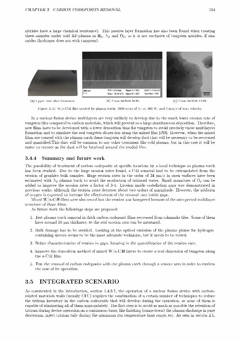
CHAPTER 3. CARBON CODEPOSITS REMOVAL 114
nitrides have a large chemical resistance). This passive layer formation has also been found when treatingthese samples under cold RF-plasma in H2, N2 and O2, so it is not exclusive of tungsten nitrides, if alsooxides (hydrogen does not etch tungsten).
(a) Upper view after treatment. (b) Cross-section SEM. (c) Cross-section TEM.
Figure 3.41: W/a-C:H �lm treated by plasma torch: 3000 sccm of N2 at 300 W, and 5 mm/s of scan velocity.
In a nuclear fusion device multilayers are very unlikely to develop due to the much lower erosion rate oftungsten tiles compared to carbon materials, which will prevent so a large simultaneous deposition. Therefore,new �lms have to be developed with a lower deposition time for tungsten to avoid precisely those multilayersformation and to simulate the real tungsten dispersion along the mixed �lm [153]. However, when the mixed�lms are treated with the plasma torch these tungsten will develop dust that will be necessary to be recoveredand quanti�ed.This dust will be common to any other treatment like cold plasma, but in this case it will beeasier to recover as the dust will be localized around the eroded �lm.
3.4.4 Summary and future work
The possibility of treatment of carbon codeposits at speci�c locations by a local technique as plasma torchhas been studied. Due to the large erosion rates found, a-C:H removal had to be extrapolated from theerosion of graphite bulk samples. Huge erosion rates in the order of 24 µm/s in open surfaces have beenestimated with N2 plasma torch to avoid the production of tritiated water. Small quantities of O2 can beadded to improve the erosion rates a factor of 3-4. Erosion inside castellation gaps was demonstrated inprevious works, although the erosion rates decrease about two orders of magnitude. However, the additionof oxygen is expected to increase the e�ectiveness of the removal rate inside gaps.
Mixed W/a-C:H �lms were also tested but the erosion was hampered because of the unexpected multilayerstructure of those �lms.
As future work the followings steps are proposed:
1. Test plasma torch removal in thick carbon codeposit �lms recovered from tokamaks tiles. Some of themhave around 50 µm thickness, so the real erosion rate can be measured.
2. Bulk damage has to be avoided. Looking at the optical emission of the plasma plume for hydrogen-containing species seems to be the most adequate technique, but it needs to be tested.
3. Better characterization of erosion in gaps, focusing in the quanti�cation of the erosion rate.
4. Improve the deposition method of mixed W/a-C:H layers to create a real dispersion of tungsten alongthe a-C:H �lm.
5. Test the removal of carbon codeposits with the plasma torch through a remote arm in order to con�rmthe ease of its operation.
3.5 INTEGRATED SCENARIO
As commented in the introduction, section 1.4.3.7, the operation of a nuclear fusion device with carbon-related materials walls (usually CFC) requires the combination of a certain number of techniques to reducethe tritium inventory in the carbon codeposits that will develop during the operation, as none of them iscapable of eliminating all of them appropriately. The �rst step is to avoid as much as possible the retention oftritium during device operation on a continuous basis, like �nishing (ramp-down) the plasma discharge in puredeuterium, inject tritium only during the maximum ion temperature time range, etc. As seen in section 2.1,

CHAPTER 3. CARBON CODEPOSITS REMOVAL 115
the redeposition of carbon codeposits and their subsequent re-erosion is very di�cult to follow, but thickercodeposits are expected to develop on surfaces under low ion �ux and at remote parts. The deposition ofthese codeposits could be partially inhibited by the injection of scavenger molecules, specially at remoteareas, as demonstrated in section 2.2. The remaining codeposits have to be removed by a combination oftechniques with the consideration of the maintenance time needed for the treatment and for the recovering ofoperational capabilities, type of areas treated, etc. As explained in Chapter 3, some techniques are capable oftreating all plasma-exposed surfaces at the same time but at low velocity, or treat all codeposits but producesdeleterious products like tritiated water. Other techniques remove carbon codeposits more quickly withoutdeleterious products but only locally, or need long shutdowns as they have to operate by remote handling,etc.
An approach based on a series of techniques to reduce the tritium inventory in ITER tokamak was proposedby G. Counsell et al in 2006 [10]. This work will be commented and extrapolated to current capabilities insection 3.5.1. A summary of the available techniques to control the tritium inventory in carbon material baseddevices, included those from this thesis, will be commented in section 3.5.2. A new �good housekeeping� orintegrated scenario for tritium inventory control based on the work from G. Counsell will be proposed insection 3.5.3. Finally, its possible application to ITER will be explained in section 3.5.4. It is necessary tonote that the objective of this section is to act as a guide for the possibility of using carbon-related materialswith tritium operation, it is not so exhaustive and thoughtful as G. Counsell work, and the aim is only tocomplement and to try to extrapolate it.
3.5.1 Motivation
Much work has been done since the proposal of the �good housekeeping� by G. Counsel et al in 2006 [10],represented in Table 1.1. Codeposits removal techniques have been improved in both laboratory [9,44,92,104,112,126,135], experimental nuclear fusion devices [14,96�98,115,154], and new strategies have been developedunder suggest a retention between 0.02 and 2 g per full-power discharge [6]. All these works lead to moreoptimistic predictions for ITER, although it does not solve completely the problem of tritium retention incarbon codeposits. Because of this, and due to �nancial issues, ITER will not work with carbon tiles at thestrike points (see glossary). The initial plan was to replace them by tungsten ones after 2-3 years, and thetungsten themselves would be changed after 7-8 years. Now ITER will start directly with tungsten tiles,which has to last 10 years until the �rst year-long shutdown. However, the operation with carbon tiles wouldallow to gain the experience needed to operate safely the device, and to predict and mitigate o�-normal eventslike disruptions and large type I ELMS without risk of render unusable the divertor tiles due to melting, ascould happen with tungsten (refer to section 1.2.3 for a detailed description). In a worst-case scenario, ifITER could not be operated safely with tungsten tiles at the strike points, then CFC tiles could be installed,and the tritium retention could be controlled by the techniques here proposed. On the other hand, thereare new experimental nuclear fusion devices which will operate with carbon-materials walls: W7X and JT-60SA. They could extrapolate the knowledge acquired for the control of carbon codeposits in ITER for theirpossible operation with tritium. Even more, a good part of the techniques here proposed will be useful totreat beryllium codeposits with tritium, and the one retained at the surface of tungsten.
3.5.2 Summary of techniques for tritium control
The summary is given in Table 3.8. Most of these techniques have been previously commented in section 1.4.3.The analysis has been done oriented to the carbon codeposit removal in ITER, but it can be applied to anyother future experimental nuclear fusion device as W7-X or JT-60SA. The principles of each technique arebrie�y described, while the merits and shortcomings are more deeply commented. A rough estimation of thecarbon codeposit erosion, or the detritiation extrapolated to ITER is also given. For detritiation quanti�cationall codeposits are considered, not only carbon ones, but also the ones developed with beryllium, and surfaceimplantation into tungsten. Notwithstanding, the scope of this work is not to study in detail each technique,just to give an overview.
3.5.3 Good housekeeping
A general guide for the application of the techniques for tritium control described in Table 3.8 will be givenhere. No speci�c reactor has been considered, as its wall materials or chamber conditioning (e.g. coatings)could be modi�ed along his lifetime. Instead the most typical wall materials combination and chamberconditioning will be used, considering that carbon materials (graphite, CFC, etc.) are present at least at thestrike points, where their properties are more useful. The only exception is lithium conditioning, it has notbeen considered due to its completely di�erent problems related to tritium retention. Moreover, the high
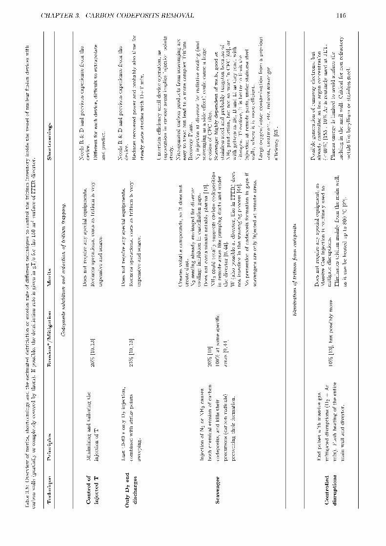
CHAPTER 3. CARBON CODEPOSITS REMOVAL 116
Table3.8:Overviewofmerits,shortcomingsandtheestimateddetritiationorerosionrate
ofdi�erenttechniques
tocontrolthetritium
inventory
insidethevesselofnuclearfusiondevices
with
carbonwalls(partiallyorcompletely
covered
bythem
).Ifpossible,thedetritiationrate
isgiven
ingT/sforthe150m2surface
ofITERdivertor.
Technique
Principles
Erosion*/Mitigation
Merits
Shortcomings
Codeposits
inhibitionandreductionoftritium
trapping.
Controlof
injectedT
Minimizingandtailoringthe
injectionofT
20%
[10,13]
Does
notrequireanyspecialequipments.
Reducesoperationalcostsastritium
isvery
expensiveandscarce.
NeedsR&Dandpreviousexperience
from
the
device.
Di�erentforeach
device,di�cultto
extrapolate
andpredict.
Only
D2end
discharges
Last40-80sonly
D2injection,
combined
withstrikepoints
sweeping.
25%
[10,13]
Does
notrequireanyspecialequipments.
Reducesoperationalcostsastritium
isvery
expensiveandscarce.
NeedsR&Dandpreviousexperience
from
the
device.
Reducesrecovered
pow
erandprobablyalsotimefor
steadystate
studieswithD+Tmix.
Scavenger
InjectionofN2orNH3causes
both
chem
icalerosionofcarbon
codeposits,andkillstheir
precursors(carbonradicals)
preventingtheirform
ation.
20%
[10]
100%
atsomespeci�c
areas[9,44]
Createsvolatilecompounds,so
itdoes
not
create
dust.
N2seedingalreadyenvisaged
fordivertor
cooling:inhibitionin
castellationgaps.
Does
notcontaminate
notably
plasm
a[10].
NH3could
totallysuppresscarboncodeposition
inremote
areaslikepumpingductsandunder
thedivertor[9,44].
W(alsopossibleatdivertor,likein
ITER)does
notinterferein
thescavengingprocess[64].
Nopreventionofcodepositform
ationin
gapsif
scavengersare
only
injected
atremote
areas.
Uncertain
e�ciency
untildeviceoperation,as
suppressionin
remote
areasimplies
injectionpoints
study.
Nitrogenatedcarbonproductsfrom
scavengingare
easy
totreatbutleadto
amore
complexTritium
RecoveryPlant.
N2injectionatdivertorforradiativecooling(and
scavengingasasidee�ect)could
cause
alarge
erosionofCFCtiles.
Scavenger
highly
dependentofwalls,goodat
stainlesssteelandprobably
tungsten
because
of
NH3production,butnotso
much
inCFC[63],or
withgettersasBe,BandLiasthey
react
with
nitrogen.Therefore,itisbetterto
limitthe
injectionatremote
parts,under
stainlesssteel
walls,whereitismore
e�cient.
Largeoxygen/watercontaminationfrom
aprevious
vent,treatm
ent,etc,reducesscavenger
e�ciency
[63].
Eliminationoftritium
from
codeposits
Controlled
disruptions
Endpulses
withmassivegas
mitigateddisruptions(D
2+Ar
mix).Flash
heatingoftheentire
main
wallanddivertor.
10%
[13],butpossibly
more
Does
notrequireanyspecialequipment,as
MassiveGasInjectionisroutinelyusedto
mitigate
disruptions.
Eliminatestritium
mainly
from
themain
wall,
asitcanbeheatedupto
800°C
[22].
Possiblegenerationofrunaw
ayelectrons,but
alreadycontrolled
atlowargonconcentration
(<40%)[155].10%
ArisroutinelyusedatJET.
Plasm
aenergyislimited
toavoid
surface
tile
meltingin
themailwall.Criticalfornon-refractory
metalslikeberyllium
orstainlesssteel.
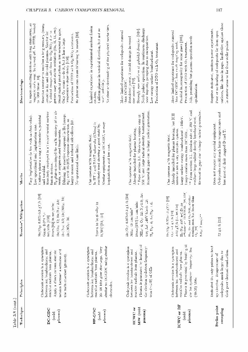
CHAPTER 3. CARBON CODEPOSITS REMOVAL 117Table3.8(cont.)
Technique
Principles
Erosion*/Mitigation
Merits
Shortcomings
DC-G
DC
(cold
plasm
a)
Codepositerosionisasynergism
betweenionbombardmentand
reactiveradicalsfrom
plasm
a.
Apply
adirectcurrentelectric
tensionbetweenelectrodes
and
themain
chamber
(ground).
He/O2:0.075-0.3gT/h[10]
Gaps:0.024-2.4
nm/min
[156]
From
[92]in
nm/min:
He/O2:12;He/N2:2.6;
H2/N2:3.5;He/NH3:16;
He/NO2:50.
Easy
implantation(a
fewrodsaselectrodes).
Low
operationalandimplantationcost.
Uniform
plasm
aalongalldirections,poloidal
andtoroidal.
Routinelyem
ployed
inallexperimentalnuclear
fusiondevices.
H2plasm
aenvisaged
forwallsrecoveryafter
air
vents,oroxygen-relatedtreatm
ents.
Dilutingthereactivecompoundin
He(except
H2)until10-20%
improves
dissociation,so
larger
erosionandreducedside-e�ects[10].
Nooperationaltimelimit.
Insuperconductingdevices
only
longshutdow
ns,as
magneticcoilsmustbeturned
o�.In
ITERlimited
to1000times
[10].
Reactivetreatm
entsrequires
alongrecovery(m
any
hours)in
H2andHecold
plasm
as.Shorter
for
N-relatedcompoundsthanforO2/NO2dueto
getterseasy
andstableoxidation(Be,B,Li,etc).
Smallradicalproductionso
lowremovalin
gaps.
Only
O2seem
sto
doit,butithasalarge
temperature
dependency
[156].
ProductionofDTOwithO2/NO2treatm
ent.
Heplasm
ascancause
blisteringin
metals[22].
HF-G
DC
(cold
plasm
a)
Codepositerosionisasynergism
betweenionbombardmentand
reactiveradicalsfrom
plasm
a.
20-100kHzglowdischarge.
Very
similarto
DC-GDCusingsimilar
electrodes.
Seemsto
besimilarto
ICWC[22,154]
Canoperate
withmagnetic�eld.
InHT-7
andEASTtokamaks(China)is
routinelyusedshow
ingagoodstability.
SimilarequipmentsasDC-GDC,so
easy
implantationandlowcost.
Limited
experience
inexperimentalnuclearfusion
devices.
Uniform
plasm
ain
toroidaldirection,butnotso
much
poloidaly.
Noclearunderstandingofthephysicalmechanism.
ECWCor
MW
(cold
plasm
a)
Codepositerosionisasynergism
betweenionbombardmentand
reactiveradicalsfrom
plasm
a.
Plasm
aisgeneratedbyheatingat
theelectroncyclotronfrequency:
tens(∼
170)ofGHz
He/O2:0.075-0.3gT/h[10]
NH3:40nm/min*
From
[157]in
nm/min:
NH3:4;O2:12;N2:1.9;Ar:
0.8;Ar(-140Vbias):12;
H2-D
2:4;Ar/D2:1.6.
Canoperate
withmagnetic�eld.
Alreadyinstalled
forplasm
aheating.
*From
section3.1.Maximum
erosionrate
at
350°C
andlargeradicaldensity
bombardment.
Rem
ovalin
gapsdueto
largeradicalgeneration.
More
limited
experience
forcodepositsremoval
thanDC-GDC.
Restrictedpow
er,itcould
damagein-vessel
components[22].
Strongly
non-uniform
atpoloidaldirection[101].
Needspulsed
operation.In
continuousdischarge
poorimpurity
pumpingdueto
redeposition.
Low
energysurface
bombardment.
ProductionofDTOwithO2treatm
ent.
ICWCorRF
(cold
plasm
a)
Codepositerosionisasynergism
betweenionbombardmentand
reactiveradicalsfrom
plasm
a.
Plasm
aisgeneratedbyheatingat
theioncyclotronfrequency:few
(40-55)MHz
He/O2:0.375-1.5
gT/h[10]
O2:∼1gT/h[10]
3-12gT/h[14,98,158]
H2/N2:30%
a-C:D;no
e�cientatTEXTOR.[98,158]
H2,D2andD2/NH3similar
erosionrate,butlowerthan
O2[98]
NH3:7nm/s**
Canoperate
withmagnetic�eld.
Alreadyinstalled
forplasm
aheating,butICH
antennasare
averycomplexsystem
.
Largesurface
energybombardment>10keV.
Larger
erosionratesthanDC-GDC.
**From
section3.1.Erosionrate
at350°C
and
medium-largeradicaldensity
bombardment.
Rem
ovalin
gapsdueto
largeradicalgeneration.
More
limited
experience
forcodepositsremoval
thanDC-GDC,butmuch
ongoingwork.
Poloidalinhomogeneity
forsomegases[101].
ProductionofDTOwithO2treatm
ent.
NH3promisingbutplasm
aoperationneeds
optimization.
Strikepoint
sweeping
DedicatedD2only
pulses
toheat
updivertor.Tem
perature
of
codepositsmuch
larger
dueto
theirpoorthermalconduction.
72gT/h[22]
Does
notrequireanyspecialequipment.
Codepositscould
reach
largetemperaturesand
lose
mostoftheirtrapped
DandT.
Requires
dedicated,medium
pow
erexperiments.
Poorornoheatingofcodepositsfarfrom
open
surfaces,likethose
ingaps.Ine�ectiveagainstthose
inremote
areasorfarfrom
strikepoints.

CHAPTER 3. CARBON CODEPOSITS REMOVAL 118Table3.8(cont.)
Technique
Principles
Erosion*/Mitigation
Merits
Shortcomings
D2only
discharges
Rem
ovalofTdueto
codeposits
erosionandisotopicexchange.
2gT/h[10]
Does
notrequireanyspecialequipment.
Experience
inJETDTE1campaign
Requires
dedicated,medium
pow
erexperiments.
Limited
tritium
elimination.
Vacuum
baking
Heatupthewallsto
release
hydrogen
bydi�usionor
decomposition.
90%
forBe,and10%
for
a-C:H
at350°C
[14].
Does
notrequireanyspecialequipment.
Envisaged
forvesselvacuum
conditioning.
Su�cientforberyllium
codepositsattechnically
availabletemperatures[10].
Ine�ectiveforcarbonandmixed
codeposits.a-C:H
requires
550-750°C
[11�14].
Requires
afewdays:only
medium-longshutdow
ns.
Thermo-
oxidation
Bakingwallsin
1-1000mbarof
reactiveatm
osphere.
Causesthe
reactionofcarboncodepositsinto
volatilemolecules
Di�cultto
estimate
asit
dependsoncodeposit
thickness.
Timefor95%
removalat50
PaNO2[105,157]:
350°C
3-5
min;275°C
15-25
min:200°C
274-457min.
Does
notrequireanyspecialequipment.
Erosionrate
proportionalto
initialcodeposits
thicknessdueto
theirporosity.
Exponentialerosionrate,so
fasterosion
availablealongallthevessel.
Easy
removalin
gapsandin
remote
areaswhere
codepositsare
softandmore
reactive.
NO2canremovecarboncodepositsatasalow
temperature
as200°C
(sub-divertor
temperature
forITER)[105,157].
Only
longshutdow
nsasitrequires
arecoveryas
vesselairvent(a
fewdays)[115].
SlowO2erosionat350°C.NO2much
larger
erosionbutishighly
toxicandcorrosive.
InO2slow
removalofC,whichcould
leavea
reactive�lm
speciallywithimpurities
likeW,B,
Be,etc.
Could
originate
dustandimproved
hydrogen
absorption.LessproblemswithNO2due
toitslarger
reactivityto
C[105,157].
O3andNH3tested,buterodesubstrate
ormake
depositsto
�ake(generatingdust)[10,157].
Laser
ablation
Alargepow
erlaserablatessurface
inducingalsoatomicandradicals
emission.
5m2/hfor10μm
deposit[22]
1m2/hfor50μm
[125]
Quickerosion.
Completely
eliminatesanycodepositnomatter
composition.
Producesmainly
molecularhydrogen,whose
tritium
recoveryiseasy
[111].
Alsovalidto
treattungsten
surfaces,butwill
produce
dustandsurface
damage.
Needsremote
handling,so
only
longshutdow
ns.
Destructive:
producesmuch
dustin
therangeof
fewµm,whichcanbedangerous.8-20µm
dust
particlescontains40-80%
oftheoriginalfuel,and
>20µm
almostall.
Low
removalin
gaps[125].
Notokamakexperience.
Laser
induced
desorption
Alowpow
erlaserheatupsurface
>1800K,bulk
>900Kinducing
hydrogen
moleculesdesorption.
0.06m2/hfor10µm
deposit[22]
Nodestructive.
Producesgasmoleculeswhose
tritium
recovery
iseasy
:H2and10-15%
CnHm[134,145].
Rem
oves
retained
hydrogen
from
carbon
codepositsbutalsomixed
withberyllium,
boron,tungsten,etc.
Itcanalsodesorb
hydrogen
from
tungsten
uppermostsurface.
Needsremote
handling,so
only
longshutdow
ns.
Slowtechnique,speciallyin
thicker
codeposits(tens
ofµm),orwhen
mixed
withimpurities
(W,Be,B,
etc)
astheirhydrogen
di�usioncanbelow.
Leaves
reactivecodepositsthatcould
absorb
H[14].
Low
removalin
gaps[125].
Notokamakexperience.
LocalRF
discharges
Plasm
aisgeneratednearthe
surface
tobetreatedattherange
ofioncyclotronfrequency
(13.56MHz).
Columnar[23]:Ar/air:
open:10-40nm/min.Gaps:
240nm/min
Torch***[152]:N2:open:
24µm/s.Gaps:1.2mg/min.
N2/O2:open:96µm/s.
Gaps:4.8mg/min.
***(extrapolatedfrom
graphiteat400°C).
Hugeerosionratesin
plasm
atorchexpected.
Plasm
atorchheatupsurface
enhancing
reaction.
Appropriate
totreatsomespeci�careaswith
thickcodeposits.
Rem
ovalin
gaps.
Needsremote
handling,so
only
longshutdow
ns.
Only
laboratory
experiments.Uncertain
operation
intokamaks.
Veryinhomogeneousremovalforcolumnarplasm
a.

CHAPTER 3. CARBON CODEPOSITS REMOVAL 119
reactivity of lithium with carbon makes their combination very inadvisable. The general guide for a possibleintegrated scenario in a future nuclear reactor under tritium operation is given in Table 3.9. The selectedtechniques, their integration into a nuclear fusion device maintenance schedule, and their limitation undersome materials combinations are now detailed:
� Control of injected tritium: e�ective at any wall material, specially when the most part of the walls aremade from carbon-related materials. Good for operational economy (less tritium injected).
� Only D2 end discharges with strike point sweeping: most of the tritium retained at strike points vicinitywill be released. No material limitation is expected, but this technique will be more e�ective if theentire divertor is made of with carbon materials due to the large quantity of codeposits that will developaround them. Nonetheless, it will also be partially e�ective to reduce surface tritium retention at metals.Strike point sweeping should be employed at all discharges, except if the experiment speci�cally doesnot allow that. Moreover and some dedicated pure D2 pulses with strike point sweeping can be madeat the end of the weekly experimental session for a larger hydrogen elimination.
� Scavenger at remote areas: injection of NH3 at remote places will practically suppress the formationof carbon codeposits at those areas. However, a initial study on the injection points has to be madeduring the nuclear fusion device construction. During the initial device operation the quantity to beinjected can be calculated by inspection of the places where more carbon codeposit develops (preferablyin a phase where no tritium is injected). As the ammonia will not enter the divertor (it is at largerpressure) it will not have any negative e�ect on plasma or wall materials. No large excess of ammoniashould be injected to reduce isotopic exchange with tritium, and hence its treatment in the Tritiumrecovery Plant.
� Scavenger at divertor: during nitrogen seeding for radiative cooling at the divertor the formation ofcarbon codeposits will be reduced, and also part of the previously developed will be eroded by chemicalsputtering. However, the carbon substrate will be eroded also, although at a much lower rate. Thismakes (almost) incompatible the presence of carbon materials at the divertor with continuous operationunder nitrogen seeding. On the other hand, as carbon atoms have also very good radiative coolingproperties, the injection of nitrogen, or any other seeding impurity, will probably not be necessary.Nitrogen seeding could be applied on a weekly basis, or at a very low rate, to erode the carbon codepositpreviously deposited with a reduced damage to the carbon substrate.No adverse nitrogen seeding operation with beryllium and boron has been found in JET and ASDEXtokamaks respectively. If tungsten is installed at the divertor it has even a bene�cial e�ect, as thedevelopment of tungsten nitrides reduces the tungsten sputtering and thus plasma core contamination,as will be seen in Chapter 4.
� Controlled disruptions: with this technique part of the tritium trapped in codeposits at the main wallwill be released, but not so much at the divertor, where lower surface temperatures will be reached. Ifcarbon materials are restricted at the strike points, then carbon codeposits will only develop aroundthem and this technique will not be very e�ective on them. On the other hand, this technique isvery e�ective to remove the tritium and other contaminants at the surface of other materials likeberyllium, boron, and in a lower rate, tungsten [159]. The best frequency for the application of controlleddisruptions will be weekly, or even diary in the �rst discharge of the day and/or in the midday. It isnecessary to note that usually 10% of the discharges end in a disruption, so unintentional controlleddisruptions will always be present. In a diary schedule it also helps to control the impurity content inthe vacuum vessel, improving the performance of subsequent discharges [159]. However, it is necessaryto control the energy of the plasma to avoid surface melting of not-refractory metals (like beryllium),specially at some speci�c tiles like start-up limiters.
� ICRH or HF-GDC cold plasma: ICRH is the most likely cold plasma technique to be routinely used,but if HF-GDC demonstrate its availability then it should be used instead due to its easier and moreeconomic operation. Independently of the technique used, diverse plasmas should be done at di�erentschedules:
� Interpulse: in an advanced nuclear fusion device between each pulse there will be around 0.5-1h of time that can be used for non-invasive plasmas. D2 can be used for a slight detritiation byisotopic exchange and sputtering, or He for an additional impurity level reduction and for plasmadensity control enhancement (eliminating the previously retained D and T from walls). He coldplasmas are essential in devices with carbon in the main wall as the hydrogen isotopes retentionat the surface is very high, which causes the plasma density control to be di�cult. No adverse
CHAPTER 3. CARBON CODEPOSITS REMOVAL 120
e�ect on any material is expected for short He plasma. D2/N2 or D2/NH3 plasmas can also bedone if the N contamination can be quickly reduced to operational levels (see next paragraph).
� Overnight: pure D2 or He plasmas can be done, but due to the larger available maintenance timeis better to use more e�cient plasmas for carbon codeposit removal, followed by pure D2 and/orHe recovery plasmas to eliminate the introduced impurities. A D2/N2 or D2/NH3 plasma can bedone (usually in a time ratio of 1:4-5 with respect to the plasma recovery time). Depending on thecarbon codeposit erosion rate (much larger in D2/NH3, but it is more expensive) the D2 recoveringplasma can be shorter. Moreover, as seen in section 3.1 both ICRH plasmas are expected to bee�cient inside castellation gaps, but more e�ciency is expected with NH3. Also depending onthe chemical resistance of the surface nitrides developed (critical with tungsten, not so much withberyllium), the needed D2 plasma recovering time has to be larger. If the subsequent discharge usenitrogen seeding, then the D2 plasma recovery time can be reduced or even suppressed if N fromthe main wall are e�ciently screened out from the plasma core. NH3 will leave some H impuritiesin the vessel but they are bene�cial as some small amount, ∼3%, is needed for ICRH operation.In the presence of tungsten walls the ammonia production, and hence carbon codeposit erosion,during D2/N2 plasmas is enhanced [160,161]. Boron reduce carbon reactivity, so longer treatmentsare needed if the device uses boron conditioning.
� Weekends: pure D2, He or D2/N2 can be applied, but also oxidative plasmas like He/O2 andHe/NO2 can be used. They are more e�cient, but they require long recovery plasmas due to thelarge oxygen uptake by the getters routinely used at all experimental nuclear fusion devices. Insome cases like B and Li the oxides are very stable and its gettering properties cannot be easilyrecovered (usually to recover it, a fresh B or Li �lm is applied). Furthermore, the production oftritiated water will also be a serious drawback.
� Trimester and longer: same treatments as at weekends can be applied. Now the full device wallsor just divertor walls can be baked to allow for tritium outgassing (like from beryllium), and toenhance the carbon codeposit elimination, specially inside castellation gaps. As seen in section 3.1this is the case for D2/NH3 ICRH plasma, at a lower rate for D2/N2 plasma, and it is also e�ectivefor He/O2 plasmas [156] . This will also reduce the needed recovery time, as the walls uptake lessimpurities.
� DC-GDC cold plasma: limited to device start-up and trimester schedule when the superconductingmagnetic coils are shutdown. The same plasmas as with ICRH or HF-GDC can be used: D2, He,D2/NH3, He/O2, etc. But as longer times are available oxidative plasmas can be applied as they aremore e�cient, as long as the expected tritiated water production is not a problem. Baking the walls ofthe full device or only at the divertor will enhance the removal and recovering processes.
� Vacuum baking: heating the walls up to 275-350 °C will release most of the tritium trapped at thesurface of some metals like beryllium, but only a small part from others like tungsten [13]. However, itwill not release the tritium trapped in the bulk or in traps in the crystal structure as the ones created byhigh-energy ions and neutrons [128]. For carbon codeposits much more temperature is needed, 550-750°C [11�14], not technically feasible by baking. The time needed to heat up and cool down the walls willdepend completely on the device design. Usually this take a few days, so this technique will be limitedto trimestral and longer maintenance periods. Furthermore, baking will greatly improve the e�ciencyof cold plasma techniques, so it is highly recommended to be used at the same time. Once the coldplasma is stopped the walls should be kept baked to reduce the needed recovery time.
� Thermo-oxidation: as both O2 and NO2 will produce a great quantity of tritiated water they shouldbe used only after other techniques have been done, and in this way, eliminate all the residual carboncodeposits left by them (specially those at remote parts). Furthermore, a long time is needed torecover operational conditions, as in an air venting [115], as the oxygen getters (B, Be, Li, etc) mustbe regenerated and the surface oxides eliminated. Therefore, this will limit the usage of this techniqueto long shutdowns. O2 has not shown any adverse e�ect on nuclear fusion device equipment [115], butlarger temperatures and times are needed compared to NO2, refer to section 3.2 for a detailed analysis.Moreover, NO2 has shown e�ectiveness even at the low temperature achievable in remote parts: 200°C. At larger temperatures it can remove the typical carbon codeposits in less than three minutes nomatter the thickness. It can also eliminate very e�ciently pure carbon codeposits (or with low tritiumcontent) and dust left by other techniques like laser ones. The selection of O2 or NO2 must be doneconsidering the carbon codeposits nature, locations and the achievable baking temperature, but due tothe low frequency needed it would be better to use NO2 due to its much larger e�ciency if no damageto device equipment is found.

CHAPTER 3. CARBON CODEPOSITS REMOVAL 121
As an exception, if the reactor has not been operated with tritium, thermo-oxidation, specially NO2,can be used in a more frequent schedule, as trimester. Due to NO2 large reactivity towards carboncodeposits (only minutes are needed), the expected recovering time will be lower.
� Laser ablation and induced desorption: as remote handling is required these techniques are limited toonly long shutdowns in most devices (although new designs may allow shorter schedules). Both tech-niques are suited for thick codeposits at speci�c areas. Due to the large temperatures achieved in bothtechniques, codeposits from di�erent materials are e�ciently eliminated, so no material incompatibilityis expected. Laser ablation is a much faster technique, but the possible damage to the substrate if thelaser power needs to be high, and the large dust production may favor the utilization of laser induceddesorption. In any case, the laser treatment must be followed by another technique to recover or elim-inate the produced dust by ablation (which will move to remote parts as under the divertor cassettes),or to eliminate the reactive carbon �lms left by induced desorption. As those dust and carbon �lmswill have low tritium, thermo-oxidation with NO2 is highly suited to eliminate them.Laser induced desorption can be employed to recover the tritium trapped in the surface and part of theone trapped in the bulk of metals like beryllium and tungsten, as no other technique is able to do that.
� Plasma torch: it requires remote handling so it will be limited to long shutdowns in most devices. Itcan be employed if cold plasma techniques are not e�ective to completely remove the codeposits incastellation gaps. If the produced dust and the carbon �lm left by the laser techniques are provendi�cult to eliminate, plasma torch can be used to remove thick codeposits at some speci�c areas. Thistechnique have no strong incompatibility with any material, but getters, which are reactive towardsthe gas used (N2 and O2 as seen in section 3.4), may require recovery treatment. In this case, as onlylocal areas need to be recovered, perhaps the plasma torch using a noble gas at lower power and larger�uxes may be su�cient.
3.5.4 Application to ITER
The possible maintenance schedules in a future nuclear fusion device with tritium retention rates as thoseestimated for ITER has been taken into account to compare the in-vessel tritium with and without theintegrated treatment in Table 3.9. In this way the ITER in-vessel mobilizable tritium limit, 700 g, wouldbe reached in approximately three months, while with the integrated treatments for tritium control it couldbe operated during more than two years without any months-long (annual) shutdown. The best treatmentsduring each maintenance period for any material mix can be extracted. In the case of the previous materialmix design for ITER: beryllium at the main walls, tungsten at the divertor and CFC at the strike points, thefollowing conclusions have been done:
� All the techniques during the plasma pulse have a good e�ciency.
� Between pulses, a D2 ICRH or HF plasma can be done. It can be followed by a He ICRH or HF plasmafor a better density control during the next pulse.
� At overnight and during weekends D2/N2 ICRH or HF plasma would be more e�ective than pure D2.D2/NH3 is more e�ective, but NH3 is corrosive for inlet piping, so it should only be used if D2/N2
plasmas are ine�ective. It needs to be followed by a He ICRH or HF plasma to eliminate the retainedN at the surface.
� After the nitrogen-related ICRH or HF plasmas, the more e�cient He/O2 and He/NO2 plasmas canbe done to eliminate more carbon codeposits. As these plasmas need longer recoveries, they should belimited to trimester or long weekend shutdowns. However, the production of tritiated water could belarge, and must be balanced with the larger carbon codeposits removal.
� During very long shutdowns the tritium from thick codeposits should be released by laser desorption.Afterwards the residual codeposits left by this technique will be eliminated easily together with othercodeposits at too inaccessible parts by a subsequent thermo-oxidation with NO2. Laser ablation can beconducted in a atmosphere of oxygen to reduce the dust size and tritium content, or be followed by athermo-oxidation with NO2 if the produced dust is demonstrated to be eliminated (the dust will usuallymove to remote parts at approximately 200 °C). Plasma torch can be used instead of laser techniquesif it has been su�ciently developed.

CHAPTER 3. CARBON CODEPOSITS REMOVAL 122Table3.9:Possibleintegratedscenariofortritium
controlin
afuture
nuclearfusiondevicewithdi�erentwallscombination(consideringtheirassociatedretentionandinteractions)andcarbon-
relatedmaterials.Basedon�goodhousekeeping�byCounsellet
al.[10].Ameantritium
retentionof1gper
pulseisconsidered,takingITERpulses
asaguide(fullpow
er,400s,10pulses/day
and5days/week).""":Essential;"":Highly
recommended;":E�ective;
≈limited
oruncertain
e�ectiveness.
Schedule
No
action
IntegratedT
control
%Tremoval
ormitigation
Proposedtechniques
all-C
Be/C
B/C
*/W/C
*/ss**/C
Duringthepulse
1g
1g�
0.5g
50%
Controlofinjected
T"""
"""
""
""
""
D2-only
endpulses
withstrike
points
sweeping
"""
"""
"""
""
""
60-100%
Scavengeratremote
areas
"""
"""
"""
"""
"""
Scavengeratdivertor
≈"
"""
"
Interpulse(1
h)
1g
0.5g�
0.35g
30%
D2IC
RH
orHFcold
plasm
a≈
""
""
""
HeIC
RH
orHFcold
plasm
a""
""
""
Controlled
disruptions(unintentional)
"""
""
"
Overnight(10-12h)
10g
3.5g�
2.5g
30%
D2/N2IC
RH
cold
plasm
a(+
slightrecovery)
""
"""
"
D2/NH3IC
RH
cold
plasm
a(+
slightrecovery)
""
""
"""
""
Controlled
disruptions(induced)
"""
""
"
Weekly(48-60h)
50g
12.5g�
8.8g
30%
D2/N2IC
RH
cold
plasm
a(+
slightrecovery)
""
≈""
"
D2/NH3IC
RH
cold
plasm
a(+
slightrecovery)
""
"≈
""
""
He/O2IC
RH
orHFcold
plasm
a(+
importantrecovery)
""
≈≈
""
""
He/NO2IC
RH
orHFcold
plasm
a(+
importantrecovery)
""
≈≈
""
""
Experim
ents
withscavengeratdivertor
"(≈)""(≈)""(≈)""
"
Trimester(80-130h)
650g
114g�
69g
40%
Vacuum
baking
≈""
≈"
"
D2/N2orD2/NH3IC
RHcold
plasm
aswithbaking(+
slightrecovery)"""
"""
""
""
""
He/O2orHe/NO2cold
plasm
aswithbaking(+
medium
recovery)
"""
""
""
""
Anygasmix
ofpreviouscold
plasm
as(withbaking)
byDC.Sim
ilar
recovery
totheirrespective
gasmix
Sim
ilare�ectivenessto
theirrespective
gasmix.
QuickNO2thermo-oxidation(+
importantrecovery)
""
≈"
""
""
Longshutdowns
(annual)
2600g
276g�
14g
95%
Laserablation(+
dust
recovery)
""
""
""
""
""
Laserdesorption(+
carbon�lm
elim
ination)
"""
""""
"""
N2plasm
atorch(+
possiblerecovery)
"""
""
""""
""
FinalO2orNO2thermo-oxidation(+
longrecovery)
"""
"""
"""
"""
"""
*Agetter(BeorB)hasto
beaddedto
thismaterialcombination.Combinewiththechosengettercolumnusingthemost
restrictivecompatibilityorthemeanoftherecommendations.
**ss:low-activationstainless
steel.

Chapter 4
TUNGSTEN NITRIDES
Tungsten has become the main plasma facing material choice for current and future nuclear devices. Itslow tritium retention, good thermal and mechanical properties (melting temperature of 3700 K), and its lowsputtering erosion by hydrogen isotopes and helium (threshold energy of 100-400 eV) have been decisive forthis choice. However, there are some drawbacks that need to be solved. In addition to neutron-induceddamage �lower mechanical resistance, increased tritium retention, transmutation to radioactive products,etc, refer to section 1.2.4 for a detailed explanation� and plasma heat loads induced melting �ELMs,disruptions, etc, refer to section 1.2.3 for an explanations of their e�ects�, the erosion by sputtering caninduce a series of critical problems. First, even if the erosion is low �mainly caused by plasma impurities likeother wall materials, O and N from air leaks, etc�, it is not obvious that the tungsten tiles at some speci�clocations under large particle loads �as divertor strike points, see glossary� will survive until the scheduledmajor maintenance (e.g. in ITER this is 10 years). Second and more critical, as seen in section 1.3.1, theeroded tungsten atoms can enter the plasma core if not su�ciently screened out. Its concentration is limitedto <10-5 due to its large radiation at the temperature of the core, which will hinder the achievement of aburning plasma (refer to section 1.1.1 for details). This is the reason why tungsten is installed mainly at thedivertor region (see glossary) where it is more e�ciently screened out, while at the main wall (see glossary)low Z materials are preferred as beryllium in ITER.
An e�cient method to reduce tungsten erosion at the divertor consist on the seeding of gas impuritiesto decrease the temperature of the plasma at this region by atomic radiation. As the divertor is designedto screen out the gas particles from the plasma core, the contamination will be relatively low. However, thecontamination levels depend on the divertor design and the type of impurity seeded, refer to section 1.3.2 formore details. In this way ion temperatures as low as 10-20 eV could be reached, and hence prevent sputteringfrom the most part of the typical impurities, and reduce greatly the yield for the tungsten mass-matched(heavy) ones. Di�erent noble gases like Ne and Ar have been tested but the best results have been obtainedwith N2 seeding in ASDEX [26] and JET [27] tokamaks. In both devices an overall enhancement of theplasma con�nement was also detected. This improvement is caused by the strongly reduced power load todivertor tiles thanks to the low plasma temperature, but also because of the total suppression of W in�uxinto the plasma [28]. This last e�ect has been ascribed to the development of tungsten nitrides �lms at thesurface of the W tiles. These �lms reduce the sputtering and the possibility of a tungsten atom of beingsputtered out due to the accumulation of nitrogen at the tungsten surface, combined with the similar and highbonding energy of W-W and W-N (∼8.68 eV). Furthermore, tungsten nitrides, speci�cally W2N, have moreapplications and interests. They have been studied as di�usion barriers for interconnecting metallization inmicroelectronics due to their extreme hardness, good chemical resistance, high electrical conductivity andhigh melting point [162�167].
In this thesis, the research of tungsten nitrides properties for their utilization in a nuclear fusion devicehave been divided in two:
1. As tokamak in-situ formation of tungsten nitrides will result in too thin �lms (few nm), ex-situ coatingof tungsten tiles with tungsten nitrides will be a more viable option. Two deposition methods basedin reactive chemical sputtering and plasma nitriding have been developed. The characterization of the�lms obtained will be presented in section 4.1.
2. Afterwards, both types of �lms will be subjected to deuterium and argon plasma �uxes in di�erentdevices to test their properties, included Pilot-PSI, a linear plasma device capable of �uxes similarto the ones expected at ITER divertor. The results in terms of material resilience, surface damage,sputtering yield, and the �rst qualitative results on deuterium retention will be given in section 4.2.
123

CHAPTER 4. TUNGSTEN NITRIDES 124
This work has been done in a wide collaboration between our group at CIEMAT, Dr. Dinescu group inBucharest (Romania), Dr. Mozetic group in Ljubjana (Slovenia), and Dr. Temmerman in Nieuwegein(Holland). Part of this work has already been published [168].
4.1 TUNGSTEN NITRIDES COATING
Some transition metal nitrides as titanium nitride and chromium nitride are subjected to a great scienti�cand technological research due to their excellent physical and chemical properties: high melting point (>3000 K), extreme hardness (>2200 kg/mm2), good chemical stability, good electrical conductivity, etc. Theyhave a wide range of applications from engineering and aeronautics to microelectronics, where they act asprotective coatings and di�usion barriers. Tungsten nitrides have similar or even better properties but theirdeposition has not been properly established yet. An uniform and crystalline �lm has been proven di�cultto obtain, specially without annealing. There are two ways to obtain tungsten nitrides: by plasma nitridingof tungsten or by direct deposition.
� Nitriding: by ion bombardment the nitrogen atoms are implanted into the tungsten surface at a depthdepending on the bombarding energy [26, 169, 170]. This is the best method to simulate the tungstennitrides formation in a nuclear fusion device. At the low energy of the ions at the divertor (10-20 eV)the nitrogen cannot be implanted, but seems to be enough to react with surface tungsten atoms.
� Direct deposition: tungsten nitrides �lms are usually grown by gas methods like Chemical Vapor De-position (CVD) and Reactive Magnetron Sputtering (RMS) [162�167]. The main advantage of RMSis that it uses only simple gases as nitrogen and argon with solid W acting as cathode, not the dan-gerous gases usually employed in CVD. Furthermore, RMS can be combined with regular magnetronsputtering to deposit pure W �lms to reduce the process steps during fabrication. However, RMS isvery di�cult to optimize as the reactive gas �nitrogen in this case� can poison the cathode. Thise�ect is observed by a decrease of the growth rate and composition of the �lm when the quantity ofthe reactive gas is increased over a certain threshold, which could even stop the deposition.
In this thesis RMS technique will be employed as it has shown a series of bene�ts as will be explained insection 4.1.1, although another batch of samples based on plasma nitridation will also be grown to obtainnitrogen-rich �lms and to simulate the characteristics of the in-situ nuclear fusion device formation. Aspecial deposition chamber which allows the alternative deposition by magnetron sputtering (reactive ornot) with Plasma-Assisted Chemical Vapor Deposition (PACVD) for the plasma nitriding process has beenused. Two di�erent kind of �lms were obtained: by RMS and by alternative tungsten deposition and itsnitriding by plasma, section 4.1.2. In section 4.1.3 the �lm is characterized by di�erent techniques: ScanningElectron Microscope (SEM), Transmission Electron Microscope (TEM), X-Ray Di�raction (XRD), X-rayPhotoelectron Spectroscopy (XPS) and Auger Electron Microscopy (AES). In section 4.1.4, the results willbe discussed in terms of its possible application for protective �lms on tungsten tiles in nuclear fusion devices.And �nally, in section 4.1.5, a summary and the future work will be stated.
4.1.1 Motivation
As commented previously, the development of tungsten nitrides at the surface of tungsten tiles during thenitrogen seeding experiments is bene�cial in terms of a better plasma performance, and a lower tungstenin�ux into the plasma core [26, 28]. Among other e�ects, these bene�ts come from the reduced tungstenatoms sputtering yield due to the accumulation of nitrogen atoms at the surface, and the similar and highbonding energy of metal tungsten and tungsten nitride. On the one hand, nitrogen is more mass-matched withthe typical nuclear fusion device impurities �Be, N, O, C, etc�, so it will su�er a preferential sputteringwith respect to tungsten, which, in the other hand, present a low sputtering yield with those impurities.Nevertheless, that low sputtering could be enough to disturb plasma operation due to the large radiation oftungsten atoms, refer to section 1.3.1 for more details. Because of this, the intention of this work is double:
1. First, tungsten �lms will be subjected to a N2 cold plasma to see the thickness and properties of the�lms that can be developed in-situ at nuclear fusion devices. The idea is to check the possibility ofmaking a short N2 cold plasma in between discharges (typically 20-60 minutes apart) in order to see ifthe �lm is thick enough to survive and have an e�ect during the subsequent plasma operation.
2. Second, deposit thick tungsten nitride �lms and see if their properties of interest to nuclear fusion aresimilar to pure tungsten (high electrical and thermal conductivity, low porosity, low sputtering yield,etc). The aim will be to cover tungsten tiles with a thick tungsten nitride �lm which can survive duringa long time in a nuclear fusion device environment.
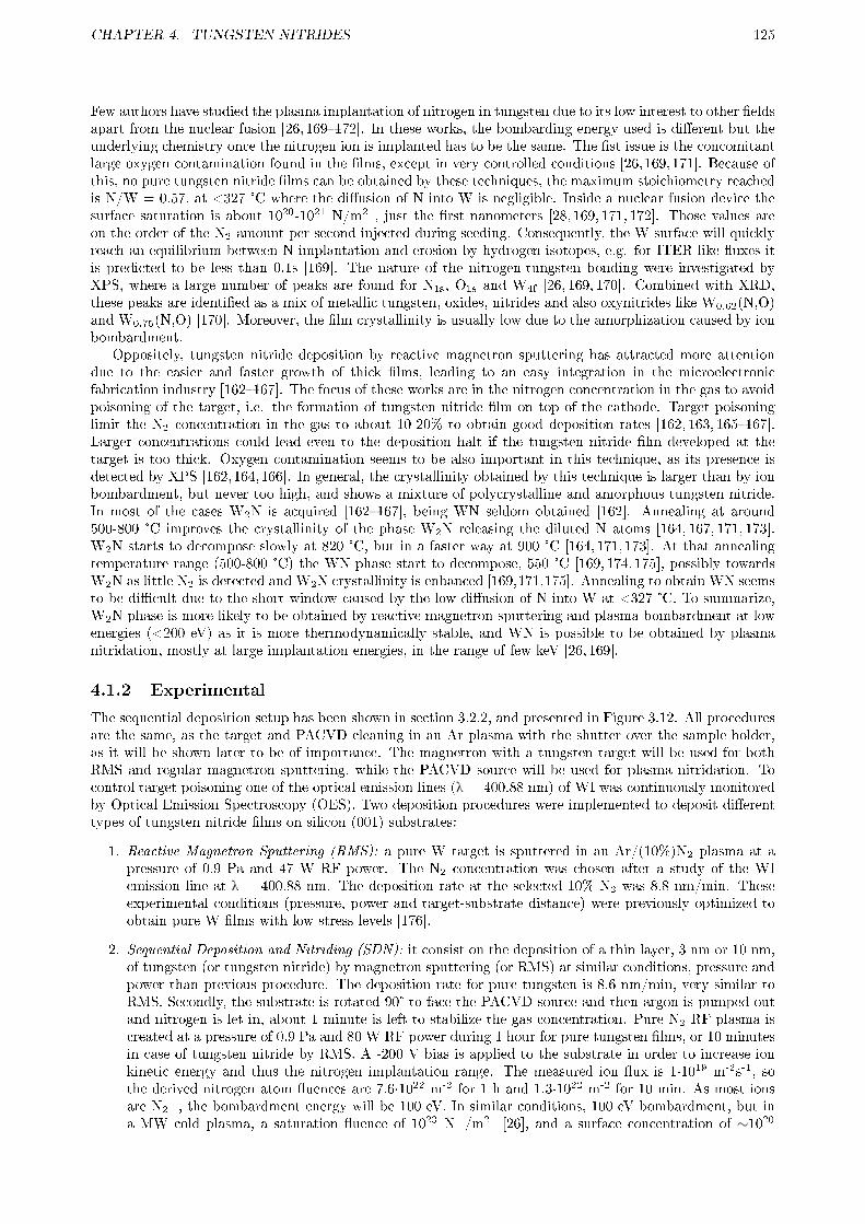
CHAPTER 4. TUNGSTEN NITRIDES 125
Few authors have studied the plasma implantation of nitrogen in tungsten due to its low interest to other �eldsapart from the nuclear fusion [26, 169�172]. In these works, the bombarding energy used is di�erent but theunderlying chemistry once the nitrogen ion is implanted has to be the same. The �st issue is the concomitantlarge oxygen contamination found in the �lms, except in very controlled conditions [26,169,171]. Because ofthis, no pure tungsten nitride �lms can be obtained by these techniques, the maximum stoichiometry reachedis N/W = 0.57, at <327 °C where the di�usion of N into W is negligible. Inside a nuclear fusion device thesurface saturation is about 1020-1021 N/m2 , just the �rst nanometers [28, 169, 171, 172]. Those values areon the order of the N2 amount per second injected during seeding. Consequently, the W surface will quicklyreach an equilibrium between N implantation and erosion by hydrogen isotopes, e.g. for ITER-like �uxes itis predicted to be less than 0.1s [169]. The nature of the nitrogen-tungsten bonding were investigated byXPS, where a large number of peaks are found for N1s, O1s and W4f [26, 169, 170]. Combined with XRD,these peaks are identi�ed as a mix of metallic tungsten, oxides, nitrides and also oxynitrides like W0.62(N,O)and W0.75(N,O) [170]. Moreover, the �lm crystallinity is usually low due to the amorphization caused by ionbombardment.
Oppositely, tungsten nitride deposition by reactive magnetron sputtering has attracted more attentiondue to the easier and faster growth of thick �lms, leading to an easy integration in the microelectronicfabrication industry [162�167]. The focus of these works are in the nitrogen concentration in the gas to avoidpoisoning of the target, i.e. the formation of tungsten nitride �lm on top of the cathode. Target poisoninglimit the N2 concentration in the gas to about 10-20% to obtain good deposition rates [162, 163, 165�167].Larger concentrations could lead even to the deposition halt if the tungsten nitride �lm developed at thetarget is too thick. Oxygen contamination seems to be also important in this technique, as its presence isdetected by XPS [162,164,166]. In general, the crystallinity obtained by this technique is larger than by ionbombardment, but never too high, and shows a mixture of polycrystalline and amorphous tungsten nitride.In most of the cases W2N is acquired [162�167], being WN seldom obtained [162]. Annealing at around500-800 °C improves the crystallinity of the phase W2N releasing the diluted N atoms [164, 167, 171, 173].W2N starts to decompose slowly at 820 °C, but in a faster way at 900 °C [164, 171, 173]. At that annealingtemperature range (500-800 °C) the WN phase start to decompose, 550 °C [169, 174, 175], possibly towardsW2N as little N2 is detected and W2N crystallinity is enhanced [169,171,175]. Annealing to obtain WN seemsto be di�cult due to the short window caused by the low di�usion of N into W at <327 °C. To summarize,W2N phase is more likely to be obtained by reactive magnetron sputtering and plasma bombardment at lowenergies (<200 eV) as it is more thermodynamically stable, and WN is possible to be obtained by plasmanitridation, mostly at large implantation energies, in the range of few keV [26,169].
4.1.2 Experimental
The sequential deposition setup has been shown in section 3.2.2, and presented in Figure 3.12. All proceduresare the same, as the target and PACVD cleaning in an Ar plasma with the shutter over the sample holder,as it will be shown later to be of importance. The magnetron with a tungsten target will be used for bothRMS and regular magnetron sputtering, while the PACVD source will be used for plasma nitridation. Tocontrol target poisoning one of the optical emission lines (λ = 400.88 nm) of WI was continuously monitoredby Optical Emission Spectroscopy (OES). Two deposition procedures were implemented to deposit di�erenttypes of tungsten nitride �lms on silicon (001) substrates:
1. Reactive Magnetron Sputtering (RMS): a pure W target is sputtered in an Ar/(10%)N2 plasma at apressure of 0.9 Pa and 47 W RF power. The N2 concentration was chosen after a study of the WIemission line at λ = 400.88 nm. The deposition rate at the selected 10% N2 was 8.8 nm/min. Theseexperimental conditions (pressure, power and target-substrate distance) were previously optimized toobtain pure W �lms with low stress levels [176].
2. Sequential Deposition and Nitriding (SDN): it consist on the deposition of a thin layer, 3 nm or 10 nm,of tungsten (or tungsten nitride) by magnetron sputtering (or RMS) at similar conditions, pressure andpower than previous procedure. The deposition rate for pure tungsten is 8.6 nm/min, very similar toRMS. Secondly, the substrate is rotated 90° to face the PACVD source and then argon is pumped outand nitrogen is let in, about 1 minute is left to stabilize the gas concentration. Pure N2 RF plasma iscreated at a pressure of 0.9 Pa and 80 W RF power during 1 hour for pure tungsten �lms, or 10 minutesin case of tungsten nitride by RMS. A -200 V bias is applied to the substrate in order to increase ionkinetic energy and thus the nitrogen implantation range. The measured ion �ux is 1·1019 m-2s-1, sothe derived nitrogen atom �uences are 7.6·1022 m-2 for 1 h and 1.3·1022 m-2 for 10 min. As most ionsare N2
+, the bombardment energy will be 100 eV. In similar conditions, 100 eV bombardment, but ina MW cold plasma, a saturation �uence of 1023 N+/m2 [26], and a surface concentration of ∼1020

CHAPTER 4. TUNGSTEN NITRIDES 126
N/m-2 [171] were found. Therefore, at the �uences and energy bombardment of this thesis the surfaceis expected to be saturated or close to it.
99.9999% purity Ar and N2 gases were used. The substrate temperature during both depositions is estimatedto be around 60-80 °C due to plasma heating. The �lm thickness and erosion were measured by a Dektak150 Veeco pro�lometer. The cross section SEM measurements were performed using a FEI model InspectS scanning electron microscope. The depth distribution of the atomic composition of the tungsten nitridelayers was investigated by AES using a PHI SAM 545 spectrometer. For electron excitation a primaryelectron beam of 3 keV and 1 µA, with a diameter of 40 µm was used. During depth pro�ling the sampleswere sputtered by two symmetrically inclined Ar ion beams of 1 keV on rotating samples in order to improvedepth resolution [177]. The sputtering rate measured on a PVD WN0.5 layer was 1.3 ± 0.2 nm/min undersimilar experimental conditions, and it will be used as a reference for the present AES measurements. Therelative sensitivity factors provided by the instrument manufacturer were used to calculate the concentrations.Relative error of AES analysis on elemental concentration is about 20%. Depth pro�le composition studieswere also studied using a SIMS Hiden Analytical device with a similar relative error. The crystallinity wasinvestigated by XRD using a Panalytical X'Pert MRD PRO system. The formation of nitride phases wasstudied by XPS in a VG ESCA 3 MKII using monocromated Al Kα radiation (1486.6 eV) or in a ESCAPROBEP with a non-monochromatic Mg Kα (1253.6 eV) source with a hemispheric analyzer Omicron EA125. Crosssection TEM samples were prepared by gluing with epoxy resin two samples face to face, and then subjectedto a mechanical thinning and ion milling. The images were taken in a 200 kV Philips Tecnai 20 TEM.
4.1.3 Sample characterization
4.1.3.1 Characterization of reactive magnetron sputtering (RMS) samples.
(a) SEM cross-section at 10% N2 (W2N). (b) Picture of the sample at 50% N2.
(c) SEM top view at 50% N2. (d) SEM top view at 50% N2 with backscattered elec-
trons only.
Figure 4.1: Images of WNx �lm deposited by RMS at various %N2 over W �lm in a silicon substrate.
The �rst step taken was the study of the nitrogen concentration necessary to avoid a large target poisoning.To do this, the WI emission line at λ = 400.88 nm was monitored at di�erent N2 gas concentrations in argon.Prior to each experiment, the W target was cleaned during 10 min in pure Ar to eliminate the tungstennitride �lm developed previously. Compared to WI emission in pure Ar, at 10% N2 the line intensity wasonly diminished to a half, but at larger concentrations (>20%) the signal completely disappears into the noiselevel. This implies that the target has developed a WNx �lm on the surface with two possible consequences:

CHAPTER 4. TUNGSTEN NITRIDES 127
almost no W atoms reach the sample, as they react with N2* from the plasma in a very fast way into tungsten
nitride clusters; or tungsten nitride clusters are directly sputtered from the surface. SEM cross section imagepresented in Figure 4.1a shows the compact columnar structure of the deposited tungsten nitride layer at10% N2 on top of a previously deposited pure W �lm. This structure suggests the good quality of the �lmsfor their application as �rst wall material in nuclear fusion devices. On the other hand, when increasing theN2 concentration at very high levels, 50%, the �lms obtained were dusty, and they easily �ake o�, as can beseen in the SEM image at Figure 4.1c, and in the picture of the silicon sheet at Figure 4.1b. Furthermore, asseen by backscattered electron image, Figure 4.1d, each grain has di�erent composition (di�erent brightness),probably a mix of the initial pure W �lm and WNx. The substrate was biased at -100 V to try to improvethe deposition rate, which could have an e�ect on the �aking of the �lm. However, after the experiment at50% N2 the vacuum chamber was full of metallic dust, probably from the WNx cluster formation in the gasand/or sputtering from target, so the biasing should not be the sole responsible for the �lm �aking o�.
Figure 4.2: XRD analysis of W2N �lm deposited by RMS(W2N RMS) and pure W �lm deposited by MagnetronSputtering (W_MS)
Figure 4.3: XPS depth pro�le concentration of a tungstennitride �lm deposited by RMS at -200 V bias.
Because of its promising �lm structure, the �lm deposited at 10% N2 was studied in more detail. Figure 4.2compares the XRD patterns of the deposited pure tungsten nitride at 10% N2 (from now on denominatedRMS sample) and pure tungsten thin �lms. A polycrystalline W2N layer with no W inclusions was found.W2N peaks are shifted to low angles giving a lattice constant of a = 0.427 nm, which dilates signi�cantly incomparison with the standard β-W2N phase (a = 0.4126 nm) [162�164,167]. The value of the mean crystallitessize was calculated as 94 nm, using a Williamson-Hall approach in order to remove the contribution of micro-strains from the peaks broadening.
W2N was also deposited by RMS using a substrate bias of -200 V to test whether larger deposition ratesor nitrogen content could be obtained. However, the opposite e�ects were found: lower deposition rates andN concentration decreasing with depth as detected by XPS depth pro�ling in Figure 4.3. These �ndingsare analogous with the previously reported by other authors in similar plasmas [165], and the ones obtainedat 50% N2. This e�ect seems to be due to a larger W sputtering at the sample surface, and an enhancedreaction of bombarding nitrogen ions with implanted N atoms, decreasing in this way the N content.
The chemical bonding of the pure W2N �lm was analyzed by XPS, Figure 4.4. The N1s peak is relatedto nitride and oxynitride bonding and is located at 397.9 eV of binding energy, in the upper range of theusually reported values of 397.0-397.7 eV [26, 164, 166, 170], and far from WN, 397.2 eV [170]. A small peakcan be recognized at 400.3 eV which could be related to the absorbed N2 [26, 170]. At the W4f region ofthe spectrum, the two core levels W4f7/2 and W4f5/2 of W2N at 33.5 eV and 35.6 eV (peaks denoted A andB respectively) are identi�ed. They are very close to other reported values for tungsten nitrides: 33.2 eVand 35.3-35.6 eV [164, 166], although this last range could be also related to tungsten oxides, 35.5 eV [170].In the upper part of binding energies of W4f region four smaller peaks (C, yellow and purple E and F) areidenti�ed, probably associated with tungsten oxides [164,166,170]. The composition of the �lm was studied byAES and XPS, giving N/W ratios of 0.32±0.06 and 0.37±0.07 respectively, very close to stoichiometric 0.33,which corroborates the deposition of pure W2N. The main impurities found were carbon and oxygen, withconcentrations around 15-20% and 8-12%, respectively. These impurities are associated with residual gasesinside the deposition chamber. This oxygen content would justify the small tungsten oxide peaks detected,but the large intensity of the peak at 35.6 eV indicates that it has to be related to W2N.
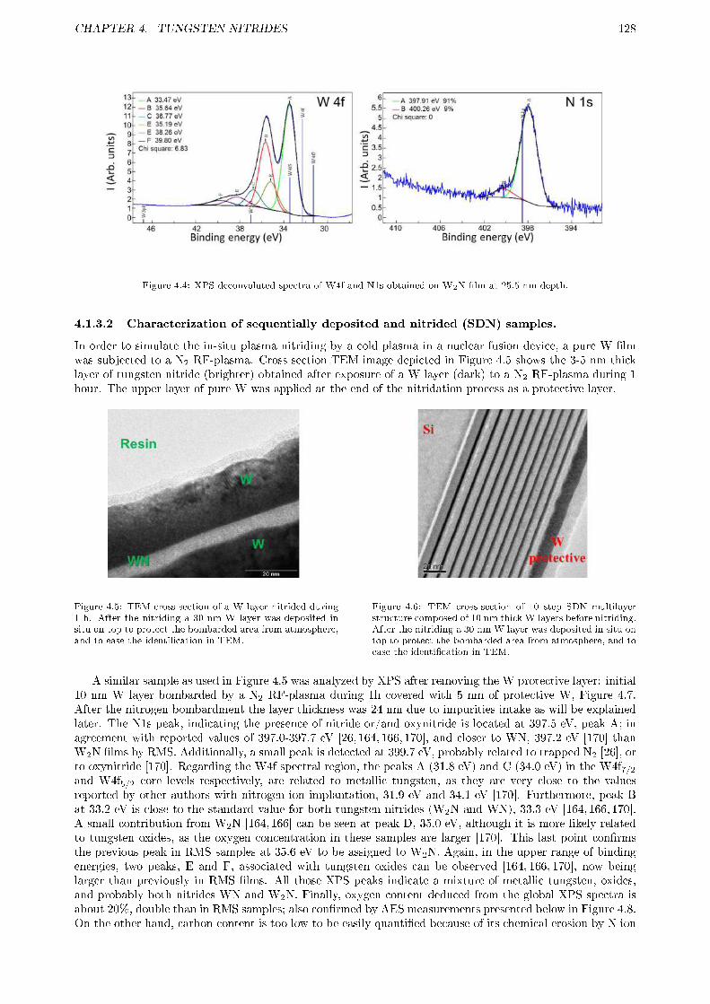
CHAPTER 4. TUNGSTEN NITRIDES 128
Figure 4.4: XPS deconvoluted spectra of W4f and N1s obtained on W2N �lm at 25.5 nm depth.
4.1.3.2 Characterization of sequentially deposited and nitrided (SDN) samples.
In order to simulate the in-situ plasma nitriding by a cold plasma in a nuclear fusion device, a pure W �lmwas subjected to a N2 RF-plasma. Cross section TEM image depicted in Figure 4.5 shows the 3-5 nm thicklayer of tungsten nitride (brighter) obtained after exposure of a W layer (dark) to a N2 RF-plasma during 1hour. The upper layer of pure W was applied at the end of the nitridation process as a protective layer.
Figure 4.5: TEM cross-section of a W layer nitrided during1 h. After the nitriding a 30 nm W layer was deposited insitu on top to protect the bombarded area from atmosphere,and to ease the identi�cation in TEM.
Figure 4.6: TEM cross-section of 10 step SDN multilayerstructure composed of 10 nm thick W layers before nitriding.After the nitriding a 30 nm W layer was deposited in situ ontop to protect the bombarded area from atmosphere, and toease the identi�cation in TEM.
A similar sample as used in Figure 4.5 was analyzed by XPS after removing the W protective layer: initial10 nm W layer bombarded by a N2 RF-plasma during 1h covered with 5 nm of protective W, Figure 4.7.After the nitrogen bombardment the layer thickness was 24 nm due to impurities intake as will be explainedlater. The N1s peak, indicating the presence of nitride or/and oxynitride is located at 397.5 eV, peak A; inagreement with reported values of 397.0-397.7 eV [26, 164, 166, 170], and closer to WN, 397.2 eV [170] thanW2N �lms by RMS. Additionally, a small peak is detected at 399.7 eV, probably related to trapped N2 [26], orto oxynitride [170]. Regarding the W4f spectral region, the peaks A (31.8 eV) and C (34.0 eV) in the W4f7/2and W4f5/2 core levels respectively, are related to metallic tungsten, as they are very close to the valuesreported by other authors with nitrogen ion implantation, 31.9 eV and 34.1 eV [170]. Furthermore, peak Bat 33.2 eV is close to the standard value for both tungsten nitrides (W2N and WN), 33.3 eV [164, 166, 170].A small contribution from W2N [164, 166] can be seen at peak D, 35.0 eV, although it is more likely relatedto tungsten oxides, as the oxygen concentration in these samples are larger [170]. This last point con�rmsthe previous peak in RMS samples at 35.6 eV to be assigned to W2N. Again, in the upper range of bindingenergies, two peaks, E and F, associated with tungsten oxides can be observed [164, 166, 170], now beinglarger than previously in RMS �lms. All those XPS peaks indicate a mixture of metallic tungsten, oxides,and probably both nitrides WN and W2N. Finally, oxygen content deduced from the global XPS spectra isabout 20%, double than in RMS samples; also con�rmed by AES measurements presented below in Figure 4.8.On the other hand, carbon content is too low to be easily quanti�ed because of its chemical erosion by N ion

CHAPTER 4. TUNGSTEN NITRIDES 129
bombardment. As this �lm is too thin for their crystallinity and other properties to be easily analyzed, andwith the aim to develop thicker �lms to be deposited ex-situ, the SDN method was implemented.
Figure 4.7: XPS deconvoluted spectra of W4f and N1s obtained on plasma nitrided tungsten sample after removing the initial5 nm of pure W
10 step SDN samples were prepared with 10 and 3 nm thick initial W layers, respectively. The SDN samplewith 10 nm nitrided W layer resulted in a multilayer structure as shown in Figure 4.6, which is corroboratedby the high resolution AES depth pro�le in Figure 4.8. The �rst layer is really composed of impurities, Feand O. They come from the initial plasma cleaning of the substrate and magnetron (Fe from the stainlesssteel holder). By Figure 4.6 it is clear that some part of the W �lm is not a�ected by the plasma (dark):about 2.5 nm. The nitride (white), WNx is about 6-7 nm. In both AES and TEM the two more externalWNx �lms are shown to be richer in N. In AES the N/W ratio of 0.5-0.6 in the outermost layers decreasesquickly to 0.33-0.35 for the deeper layers, and in TEM these outer layers are more brilliant, indicating alower mean molecular mass. Probably, each nitrided W layer is a�ected by the plasma during the followingdeposition-nitridation steps with a preferential sputtering of the lighter elements, increasing in this way theW ratio. Some tiny crystallites can be seen in the �rst two layers (closest to Si), which will be studied later inthe 3 nm initial W layers. On the other hand, a great care is necessary with this kind of multilayer structuresas the same �lm analyzed by SIMS with a poorer depth resolution gives a totally di�erent result becauseof the artifact created by an inhomogeneous depth pro�ling, see Figure 4.9. By AES it was also observed asigni�cant contamination with O, Fe and C in the nitrided layers. Most probably this is due to sputteringfrom chamber walls and substrate holder during the long plasma nitriding steps (they take around 1 h). Itis not excluded also water or residual air contamination. Finally, SDN sample thickness resulted to be muchlarger than a blank one not subjected to plasma: 190 to 110 nm. The density of tungsten and its nitrides isvery similar and both �lms seem to be compact in SEM and TEM images. Hence, the thickness increase hasto be related to the oxygen and other impurities uptake.
Figure 4.8: High resolution AES depth pro�le of 10 stepSDN multilayer structure composed of 10 nm thick W layersbefore nitriding.
Figure 4.9: SIMS depth pro�le of 10 step SDN multilayerstructure composed of 10 nm thick W layers before nitriding.
If the W initial �lm is reduced to 3 nm the multilayer structure is still present, see TEM images inFigure 4.10. The part not (or slightly) a�ected by the plasma �dark in Figure 4.10� is smaller, about

CHAPTER 4. TUNGSTEN NITRIDES 130
1.5-2 nm, while the nitrided part is larger �white in Figure 4.10�: from 13 nm in the �rst layer, closestto Si, to 8 nm from the 3rd. The most external layers have become amorphous, probably because of a localtemperature rise during the argon milling for sample preparation caused by the poor adherence of this �lmto the substrate (a special resin was used before to avoid heating in the previous preparation step). Again,the nitrogen content of the most external layers is larger than the one of the internal layers, from W/N 0.6decaying rapidly to 0.33, see Figure 4.11. The main di�erence with thicker initial W �lms is in the improvedcrystallinity, as con�rmed by XRD, Figure 4.12. The detected peak is very small and broad, but points toa mixture of WN (100) and W2N (111), as both peaks positions are near. This mix is con�rmed in highresolution images from TEM, where many nanocrystals in the nitrided layers of about 2-5 nm in thicknessare also observed, Figure 4.10b, specially in the innermost layers. The lattice parameters can be measuredin the pictures (atom to atom) and they are in most cases very compact: 0.40±0.3 nm in one directionand 0.30±0.2 nm in the other. However, there are other less compact crystals: 0.26±0.2 nm, 0.40±0.4 nmand 0.32±0.3 nm in di�erent directions. The more compact grains would correspond to cubic W2N (111) oflattice parameter a = 0.412 nm, and inter-plane distance of 0.28 nm. The other grains would correspond toHexagonal-Ditrigonal Dipyramidal Class (6 m2) WN (100) of lattice constant a = 0.289 nm and interplanedistance of 0.25 nm. Furthermore, by XPS a WN0.33 ratio was detected in most layers, which would point toa prevalence of W2N once taken into account the un-nitrided part. The same contamination problem, up to42% and 23% for oxygen and iron respectively, has been found by XPS. This result, supported by the muchlarger thickness (86 nm) of the nitrided multilayer structure, compared with the thickness (28 nm) of theW blank one (not subjected to plasma), con�rms the large contamination during the necessary long plasmanitriding step.
(a) View of all layers. (b) High resolution with nanocrystals.
Figure 4.10: TEM cross-section of 10 step SDN multilayer structure composed of 3 nm thick W layers before nitriding.
In order to be able to reduce the plasma nitriding time while maintaining a large N content, plasmanitriding of 2 nm W2N layers deposited by RMS instead of pure W layer was tested. The plasma nitridationstep was then reduced to 10 min. In high resolution AES the 50 nm thick �lm seems to be homogeneous, seecentral part of Figure 4.13. Nevertheless, by TEM a multilayer structure of 3-4 nm WN0.6 (whiter) and 1-2nm WNx (x < 0.6, darker, and most likely W2N) was still obtained, see Figure 4.14. Again, the last layer(10th) is fully amorphous, probably due to local heating by ion milling during sample preparation. Evenmore, the layers 8-9 seem to have lower N content (darker in Figure 4.14), in contrast to SDN layers withinitial pure W. There is a possibility that each step is nitrided also by the subsequent one, but a nitrogenloss at those layers during the sample preparation is more probable, as by AES (as-deposited sample) theexternal part seems to have slightly more N. Iron contamination was avoided because the sample holder wascovered with a thick layer of W2N due to the previous deposition, and the borders of the silicon sample werediscarded. However, oxygen content remains relatively high, 29±3 %, signaling again an oxidation of thelayer even at shorter plasma nitridation times.
4.1.4 Discussion
Two types of tungsten nitrides have been deposited by two di�erent methods. By RMS pure W2N �lmsof good quality were deposited. They showed a good crystallinity by XRD, better than other reported

CHAPTER 4. TUNGSTEN NITRIDES 131
Figure 4.11: XPS depth pro�le of 10 step SDN multilayerstructure composed of 3 nm thick W layers before nitriding.
Figure 4.12: XRD analysis comparison of 10 step SDN mul-tilayer structure composed of 3 nm thick W layers beforenitriding and a blank sample from non-nitrided layers.
Figure 4.13: High resolution AES depth pro�le of 10 stepSDN multilayer structure composed of 2 nm thick W2N lay-ers by RMS before nitriding.
Figure 4.14: TEM cross-section of 10 step SDN multilayerstructure composed of 2 nm thick W2N layers by RMS beforenitriding.
results [162, 163, 167, 170]. This can be ascribed to the large mean crystal size obtained in this thesis, 94nm, compared to the ones obtained in previous works, much lower: from 6.5 [162] to 15 nm [167]. Thelattice parameter, a = 0.427 nm, is far from the results of other works a = 0.414-0.416 nm [162, 164], butclose to the value reported for layers with an improved crystal size a = 0.426 nm [167]. Nonetheless, the�lms with larger crystal size, as the one of this thesis, have a more expanded lattice compared to the β-W2Nreference: 0.4127. On the other hand, tungsten nitride �lms obtained by the SDN method present poorercharacteristics. For example, a large, undesired contamination from residual vacuum gases is found if verythin W layers, 3 nm before nitridation, are used. Furthermore, an undesirable multilayer structure appearsclearly at TEM cross-section images at the tested thickness, 3 and 10 nm, specially evident in the last one.In addition to this, the N/W values are not constant, only the uppermost layers seem to have values close to0.6-0.7, while the deeper ones seem to have lost their nitrogen during the subsequent steps and convert intoamorphous W2N as its stoichiometry indicates. If in the SDN process W2N �lms are nitrided instead of pureW �lms, better results are obtained, not so much in terms of homogeneity �as they are still multilayers�,but in a larger N/W ratio �0.6�, and in a lower contamination �only oxygen is found�. This con�rmsthat reducing the plasma nitridation step by initial W2N layers instead of pure W, or increasing the ionbombardment �ux to the sample will be essential to solve the contamination problems of SDN, together witha better chamber vacuum conditioning.
Core level spectra for nitrides and oxinitrides between both types of �lms are similar, with an 0.4 eVdi�erence. This points to a similar bonding of both type of �lms, but being a�ected by ion bombardmentor more probably implanted N2, as the 400 eV peak seems to be larger in RMS W2N than in SDN tungstennitride (9 to 6.9%), compare Figures 4.4 and 4.7. On the other hand, tungsten core level spectra are very

CHAPTER 4. TUNGSTEN NITRIDES 132
di�erent for both studied �lms. RMS �lms present similar tungsten nitrides binding energies as previousworks, and also a speci�c bonding for W2N at 35.6 eV and relatively few tungsten oxides and oxinitrides werefound. Oppositely, due to their large contamination, SDN �lms seem to be a mix between metallic tungsten,tungsten oxides, oxinitrides and both types of tungsten nitrides: WN and W2N. The mix of tungsten nitridesis con�rmed by XRD and mainly in the high resolution TEM cross-section images taken on the 10 SDNsteps, 3 nm initial W �lm, Figure 4.10b. Notwithstanding, the interpretation of the core level spectra forSDN samples is very complex due to their multilayer structure. As the XPS has a depth resolution of 5 nmin W, it will probably measure both WNx �lm and the una�ected pure W underneath (for XPS a unique 10nm thick W layer was nitridated).
If tungsten nitride �lms are to be used on a nuclear fusion device, there are two options as previouslymentioned.
1. Between each discharge the tungsten tiles could be nitridated by a cold plasma treatment in pure N2 ormixed with He. Nevertheless, if the previous discharge was operated with nitrogen seeding, the wallswill be most likely saturated in N as it usually takes only 0.1-1s in ASDEX tokamak [172]. Therefore,the nitridation will not have an appreciable e�ect, as the implantation range will not be much largerthan the one caused by the discharge. Furthermore, during the cold plasma treatment other componentsof the reactor �mainly getters like Be, B, Li� could trap nitrogen into undesirable products with poorelectrical conductance, causing erosion by arcing, or an excessive contamination of N into the plasmacore during their erosion in the subsequent pulse. Although in current tokamaks like ASDEX thenitrogen legacy after a N2 seeding pulse are in the range of a few discharges [172], it is not clear thatin future nuclear fusion devices with more energetic steady state plasma and more powerful events, likeELMs, the typical tungsten nitride �lm of a few nm would survive the entire discharge, much longerthan current ones, or even the initial limiter phase before any N2 is seeded.
2. If tungsten tiles are previously coated with a thick �lm of tungsten nitride, in the range of microns, thenthe bene�ts of tungsten nitrides could be maintained until the scheduled tile replacement, as long as thetungsten tile is not melted during an o�-normal event. For this task, W2N �lms prepared by RMS havethe advantages of a relatively fast deposition rate, a decomposition temperature of 820 °C [164] (largerthan the steady state temperature of a future nuclear fusion device as ITER �300-500 °C�), and goodcrystallinity, which would lower the sputtering rate in a reactor due to the larger surface binding energy.A mandatory parameter would be low resistivity. For W2N it is reported to be within an acceptablerange, 200-300 μΩ·c.m [162,163,165,167] but larger than pure W, 5 μΩ·cm, so this conductivity loss hasto be accounted for. However, the resistivity increases usually with the N/W content up to 1000 μΩ·cmindependent of morphology [165, 167], which could render the use of SDN layers too dangerous. ForWN it can be even 11,000 μΩ·cm [163], but very low crystallinity �lms were obtained at that work, so amorphology e�ect cannot be ruled out. In any case, the WN phase is not stable at temperatures likelyto be exceeded in divertors of fusion reactors, as it decomposes at 550 °C into W2N and N2 [169, 174].Therefore, W2N reactive sputtered �lms seem to be better suited to work in a future nuclear fusiondevice.
4.1.5 Summary and future work
Two types of tungsten nitride layers have been obtained:
1. Reactive magnetron sputtering (RMS): pure, polycrystalline W2N �lms have been made. Their crys-tallinity is much larger than previous reports by other authors, which will reduce the sputtering com-pared to amorphous layers as the atom binding energy is larger, in fact it is very similar to W�W. Itsacceptable electrical conductivity �200-300 μΩ cm�and its large decomposition temperature �820°C�, make them good candidates for the application in nuclear fusion reactors. These layers are ableto be deposited in a relatively fast way (8.8 nm/min) in �lms thick enough to protect the tungstenarmor tiles in a fusion reactor, and thus decrease the tungsten in�ux into the plasma core.
2. Sequentially deposition followed by plasma nitriding of tungsten layers (SDN): These �lms present alarger nitrogen content, up to 0.6 N/W, so they are expected to present a lower W sputtering yield.Their crystallinity is very low, and consists in a mix of nanocrystals of W2N and WN. However, alarge contamination was found together with an undesired multilayer structure, even when 2 nm W2Nlayers instead of pure W were deposited initially to reduce the required plasma nitriding time. As aconsequence of this contamination the layers were not very adherent to the substrate. These e�ectsare expected to be greatly reduced in a new, better conditioned chamber. However, other issues alsoneed to be assessed as the lower electrical conductivity, WN thermal decomposition, and the very slow

CHAPTER 4. TUNGSTEN NITRIDES 133
deposition rate. The fastest deposition rate was for the initial W2N �lms, 50 nm in 10 steps, eachone requires about 12 minutes to account for changing the gas. Hence, a deposition rate of only 0.42nm/min is estimated.
In order to be able to compare the SDN �lms with the RMS ones, a very low contamination is essential.For this purpose, a new chamber is being assembled with a lower leak rate, larger ion �uxes and the possi-bility of full chamber plasma conditioning. However, SDN layers need to be further optimized to improvehomogeneity and to avoid the multilayer structure, being the most viable option the nitridation of <2 nmW2N layers. The deposition of W2N layers by RMS will need to be optimized in the new chamber to achieveor improve the crystallinity already obtained. Furthermore, once both layers have been optimized, theirelectrical conductivity should be measured to con�rm that they can be used as a plasma facing material ina nuclear fusion device. Nonetheless, the problems of SDN layers already found will probably hinder the useof these kind of �lms in a nuclear fusion reactor if they do not show a much lower sputtering rate, hydrogenretention and blistering formation than W2N �lms. This point will be addressed in the following section.
4.2 TUNGSTEN NITRIDES EROSION BY PLASMA AND FUEL
RETENTION
Since the successful results during nitrogen seeding in a full-tungsten wall tokamak like ASDEX [26], wherea reduction of the tungsten in�ux into the plasma has more recently been seen [28], and the improvement onplasma con�nement found at JET tokamak [27], an interest for tungsten nitrides formation and its e�ects onplasma has been developed. However, the conditions in future nuclear fusion devices like ITER will be muchdemanding than in current experimental devices. Furthermore, new issues will arise during the operationwith tritium, huge particle �uxes, etc. All these possible adverse e�ects on tungsten nitrides should be studiedand compared with pure tungsten in order to balance with its bene�cial e�ects. In this thesis a comparisonof the tungsten nitride �lms obtained in the previous section with pure tungsten will be carried out on thefollowing properties:
� Physical sputtering: a decrease in the tungsten atom sputtering is expected due to the accumulation ofnitrogen at the surface, its preferential sputtering, and the similar bonding energy between N�W andW�W. This decrease should be quanti�ed.
� Chemical sputtering: chemical erosion of nitrogen by hydrogen isotopes enhanced by ion bombardmentis expected. This is also related to the production of ammonia as volatile species, so tungsten nitridesare expected to su�er from chemical sputtering. It should be con�rmed that this sputtering will onlya�ect nitrogen, and in a depth equivalent to the hydrogen ion implantation range (no further erosion).
� Blistering: under large hydrogen �uxes it has been observed that tungsten materials develop blisters atthe surface. These blisters are a source of tritium retention and could also increase greatly the erosionand dust formation if they break. It is therefore necessary to investigate if blister formation is increasedor reduced with tungsten nitrides.
� Hydrogen isotopes retention: tungsten has been chosen as �rst wall material because its low hydrogenretention, among other properties. The conservation of a low hydrogen retention with tungsten nitridesneeds to be con�rmed.
Tungsten nitrides for nuclear fusion devices is an ongoing and very recent research, and much of the resultshave not even been published yet as will be commented in section 4.2.1. In order to test the previousproperties three di�erent devices will be used, from smaller to larger �uxes, being able to reach the �uxesexpected in ITER divertor. They will be detailed in section 4.2.2. The results from the exposure of tungstennitride �lms to these plasmas will be presented in section 4.2.3. The availability of tungsten nitrides forfuture and present nuclear fusion devices will be discussed in section 4.2.4. In section 4.2.5 the conclusionfrom these experiments will be given, and the ongoing work will be sketched.
4.2.1 Motivation
4.2.1.1 Tungsten sputtering
As previously commented, interest in tungsten nitrides is due to its lower tungsten sputtering rate comparedto pure tungsten in a nuclear fusion device. Tungsten is sputtered mainly by impurities as the sputteringthreshold for hydrogen isotopes and helium ions is more than 100 eV. This is specially evident at the strike

CHAPTER 4. TUNGSTEN NITRIDES 134
points in the divertor region, where energies lower than 100 eV and �uxes in the order of 1024ion/m2s areexpected. The content of some intrinsic impurities �N, O and C� is reduced by the use of getters, asberyllium in ITER. But the bombardment of other wall materials, as the getters themselves, is unavoidable,and could lead to an excessive sputtering, specially when the so-called self-sputtering with tungsten atomsoccurs (a runaway erosion, see more details in section 1.2.1).
In order to reduce the power and ion loads on the strike point tiles it is necessary to seed some gas toimprove the radiative cooling, being the most typical N2 and Ne, refer to section 1.3.2 for a full explanation.These impurities reduce the bombarding energy until the desired 10-30 eV, a more bearable range, but, on theother hand, they also cause sputtering, so both e�ects should be balanced. As can be seen in Figure 4.15 thecalculated values by TRIM (a Monte Carlo code) for nitrogen are larger than the experimental ones, exceptwhen a dynamic retention of up to 50% of N on the surface is included [26]. Oppositely, the experimentaland calculated values for Ne are similar, and larger by almost an order of magnitude than nitrogen. Thisis caused not only by its larger atomic mass but also by the accumulation of N atoms at the surface whichare preferentially sputtered. A experimental tungsten sputtering yield decrease of about 50% can be inferredfrom Figure 4.15 with respect to the theoretical one without N accumulation. On the other hand, physicalsputtering yield of di�erent tungsten nitride �lms with Ar ions has been also calculated by Monte Carlo Codessimilar to TRIM or enhanced versions of it. By SDTRIM.SP similar values to experiments have been foundfor 5 keV Ar+ sputtering of 2.5 keV N+ implanted tungsten �lms with a yield of 2-2.2 [169]. By SRIM with260 eV Ar+ a yield of 0.59, 0.42, and 0.22 for W, W2N and WN were calculated respectively [162]. As Ar ispoorly mass-matched against nitrogen, a sputtering yield decrease with %N in W is expected. Nonetheless,the sputtering yield decrease with the nitrogen content is not fully representative of the impurities inside anuclear fusion reactor as argon has a larger atomic mass than the usual seeded impurities (Ne and N2). Itwill only reproduce the reduced erosion during the massive gas injection for disruption mitigation, where ahuge quantity of gas with up to 10% Ar could be injected. However, experiments in argon could be a goodindication of the general physical sputtering decrease by impurities.
Figure 4.15: Comparison of tungsten sputtering yields obtained experimentally and calculated by TRIM from K. Schmid etal [26].
In a nuclear fusion device the composition of the �ux to the divertor will be hydrogen isotopes mixedwith helium, and a few % of nitrogen when it is seeded for radiative cooling. In tungsten-divertor devicesthe formation of tungsten nitride �lms during seeded pulses, and their preferential erosion by hydrogen inthe subsequent non-seeded pulses has already been described [27, 28, 159�161, 178]. In JET and ASDEXtokamaks, traces of nitrogen are usually detected during the subsequent 4-6 discharges [160,161,178], or untila mitigated disruption occurs thanks to the �ash cleaning of the entire walls [159] (in fact, this method hasbeen proposed to treat carbon codeposits, as can be seen in section 3.5). Chemical sputtering of nitrogenby hydrogen is con�rmed by the production of ammonia, not only during N2 seeded pulses but also duringsubsequent non-seeded ones [160, 161]. In this way the equilibrium between wall nitrogen implantation anderosion by hydrogen in conditions similar to those of ITER is expected to occur in the initial 0.1-1 s of thedischarge [169].
Few works have been devoted to the study of nitrogen erosion from tungsten nitrides by hydrogen plasma[169]. N was implanted at 2.5 keV, and the saturation was reached at 2.3·1020 N/m2 with an implantationthickness of 10 nm. That �lm presented a decrease of sputtering yield with 5 keV Ar close to the estimatedby SDTRIM.SP. Oppositely, the sputtering yield with deuterium at 2.5 keV was half than predicted: around0.022-0.044. This lower yield found is important, as the resulting erosion is even smaller than the onepredicted with a code that already simulates correctly the dynamic retention. SDTRIM.SP was also usedto estimate the W sputtering decrease with di�erent %N in a D plasma. For pure N plasma a decrease of30% of W erosion is observed. But the lower %N in the gas the lower the decrease estimating at 2 %N the

CHAPTER 4. TUNGSTEN NITRIDES 135
limit where no decrease is seen [169]. However, that work does not consider any �ux e�ect, and the �uencesstudied are 1-2·1023 ion/m2as maximum, which could be reached in only 0.1 s at the divertor strike points ofa future nuclear fusion device as ITER. Therefore, experiments at �uence, and if possible, �uxes equivalentto the ones expected in ITER are highly desirable, as the material degradation changes drastically with both,as will be seen in the next point.
In order to estimate W physical sputtering in this work an enhanced Bohdansky experimental modelproposed by Y. Yamamura and H. Tawara [179] has been used. This model is di�erent from the one previouslyused in section 2.1.1, which was more optimized for chemical sputtering. The new empirical formula is:
Yphys(E) =0.042 ·Q (Z2) · α∗ · Sn (E)
Us · (1 + Γ · ke · ε0.3)
(1−
√EthE
)s(4.1)
E is the ion bombardment energy in eV, α*(M2/M1) is an energy-independent function of the masses ofthe incident ion (M1) and target atom (M2), and Q (Z2) is a parameter which re�ect its dependence on theatomic number of the incident ion (Z2), 0.72 for tungsten,
α∗ = 0.249 ·(M2
M1
)0.56
+ 0.0035 ·(M2
M1
)1.5
; M1 ≤M2
= 0.0875 ·(M2
M1
)−0.15
+ 0.165 ·(M2
M1
)M1 ≥M2 (4.2)
Sn(E) is the energy dependence of the energy deposited in elastic collisions,
Sn(E) =84.78 · Z1 · Z2√Z
2/31 + Z
2/32
M1
M1 +M2sTFn (ε) (4.3)
Being snTF(¹) the reduced nuclear stopping power based in the Thomas-Fermi potential,
sTFn (ε) =3.441
√ε · ln (ε+ 2.718)
1 + 6.355√ε+ ε · (6.882
√ε− 1.708)
(4.4)
¹ is the reduced energy,
ε =0.03255
Z1 · Z2 ·√Z
2/31 + Z
2/32
M2
M1 +M2E (4.5)
Us is the surface binding energy of the target solid, 8.9 eV for tungsten. Γ is the contribution to sputteringof cascade collisions inside the surface layer,
Γ =W (Z2)
1 +(M1
7
)3 (4.6)
W(Z2) is a dimensionless parameter, for tungsten is 2.316. ke is the Lindhard electronic stopping coe�-cient,
ke =0.079 (M1 +M2)
3/2
M1.51 ·M0.5
2
Z2/31 · Z0.5
2(Z
2/31 + Z
2/32
)0.75 (4.7)
Eth is the ion threshold energy which depends on the atomic mass of the impinging ion and bombardedsurface material,
Eth = Us6.7
γ; M1 ≥M2
= Us1 + 5.7 ·
(M1
M2
)γ
; M1 ≤M2 (4.8)
Being γ the energy transfer factor in the elastic collision,
γ =4 ·M1 ·M2
(M1 +M2)2 (4.9)

CHAPTER 4. TUNGSTEN NITRIDES 136
Finally the factor s is a dimensionless parameter slightly dependent of target material, which for tungstenis 2.8.
4.2.1.2 Hydrogen isotope retention and blistering
Hydrogen isotopes retention and blistering have been recently reviewed by T. Tanabe [128]. Both processesare closely related, as the hydrogen isotopes retained close to the surface in voids of the crystal network cangrow until blisters of the size of microns are developed. Hydrogen retention in tungsten has been studiedby many methods: ion implantation, plasma exposure, gas charging, etc. However, the reported amounts ofhydrogen retention, and their dependencies on the incident �ux, �uence and temperature are very variableand present a complete lack of repeatability. This inconsistency is related to the di�erences in the tungstenmaterials studied: microstructures, grain structures, and impurities. As tungsten is a refractory and brittlematerial, the fabrication methods are very limited. The most usual method is hot rolling from powdermetallurgy, which leaves a large quantity of crystalline defects in the material. Annealing at 800 K mobilizesthe vacancies and impurities reducing those defects but weakening the grain boundaries. There are otherphysical methods like physical vapor deposition, magnetron sputtering, plasma spray, etc. These methodsare used to coat other components, as bulk materials are di�cult to obtain due to their layer growth nature,high porosity, and their poor mechanical properties. In most metals, hydrogen isotopes are retained in trapsof the crystalline matrix. In the case of tungsten, some materials can present a large hydrogen retentiondue to the high defect density, grain boundaries with a large number of impurities, or large porosity. At thesurface, all tungsten materials will have a large defect density, and thus hydrogen retention, caused by theion bombardment. Moreover, in a future nuclear fusion reactor the neutron �uxes will be huge, so a largenumber of traps, like vacancies, transmutation products, etc, will be created along the material bulk. It istherefore mandatory to study the hydrogen retention in tungsten materials which are available for a nuclearfusion reactor.
Hydrogen isotopes retention is studied with deuterium to distinguish from the natural protium. Fewanalysis techniques are able to detect and even less to quantify deuterium content in a solid material. Themain techniques are: Thermal Desorption Spectroscopy (TDS) and Nuclear Reaction Analysis (NRA), butLaser-Induced Desorption (LID) is also used. Opposed to results from carbon materials, the deuteriumcontent obtained by these techniques is very di�erent, being systematically the measured deuterium contentof the same samples in this way: TDS>NRA>LID [128]. This inconsistency is due to the unexpected largedi�usion of deuterium into the bulk of some tungsten materials, specially with high porosity or along grainboundaries. This e�ect contributes to the inconsistencies in the deuterium content found by di�erent authors.As NRA and LID are only able to measure the deuterium trapped in a few microns, the deeper part of the bulkwill not be measured. Consequently, only TDS should be used to quantify the deuterium content of bulk (ormore than a few microns) tungsten samples. Because of this, growth methods which leave �lms with a largeporosity like plasma spray have been shown to be unsuitable due to their large D retention [14,128,178,180].By TDS it has also been found that during ion bombardment new large-energy traps are developed, i.e. largeannealing temperatures �more than 1000 K� are needed to release the retained D [128,178]. T. Tanabe [128]proposed a model to estimate the deuterium retention along a tungsten material in a future nuclear fusiondevice: 1019-20 D/m2 at surface; 6·1022 D/m2 at subsurface until 10 um; and 1022 D/m2 up to 1 cm, which willincrease with neutron bombardment. However, he uses some upper values, specially at the surface where heclaims that up to a 10% D is possible. Those values have been refuted as an overestimation by other authors,but some experiments have shown retention values not so far from them: similar values have been found underH2 magnetron sputtering [181]; values of 1% are obtained under low energy bombardment �33 eV� [171];and more than 1% at the surface in a W �lm with 0.89 dpa has been found [129]. Notwithstanding, theestimation by T. Tanabe highlights the important tritium retention in the bulk of current tungsten materials,and the importance of the impurities and fabrication methods. Opposed to carbon codeposits, these trappedtritium cannot be easily released in-situ by any technique, and if tritium retention is �nally shown to be toolarge new removal methods should be developed.
Some defects in tungsten can trap a large quantity of H atoms, like vacancies where more than 10 H atomscan be trapped [128]. The large �uences reached in a nuclear fusion device can cause an H supersaturation intraps or in super solution states. Then it could be self-stabilized to make bubbles. Those bubbles can growinto blisters when the internal gas pressure exceeds the mechanical strength of W, in the order of GPa. Themeasured depth of the blisters is larger than the implantation rage, so it is evident that H di�uses and createssupersaturation areas under the ion bombardment range. There are two main types of blisters dependingon tungsten material manufacture as seen in Figure 4.16a: large blisters over grain sizes, which come fromexfoliation of grain boundaries at the deeper region of the saturated layers with/without slipping of a speci�cplane (most probably [110] due to the compressive stress in the H saturated layers); and dome shaped blisters,usually smaller than the grain size, originated from accumulation of high pressure gas bubbles occurring very

CHAPTER 4. TUNGSTEN NITRIDES 137
(a) Fluence 1026 D/ m2, �ux 1022
D+/m2s, and energy of 38 eV at 480
K. [182].
(b) Fluence 4.7·1025 D/m2, �ux 2·1021
D+/m2s, and energy of 45 eV at 920 K [183].
(c) Fluence 1025 D/m2, �ux 6.3·1019
D+/m2s, and energy of 1 keV at 1073 K
[184].
Figure 4.16: Surface blistering of tungsten surfaces under large deuterium ion �ux in di�erent conditions.
near to the surface. Both types of blisters can show an elastic or plastic deformation. The elastic deformationcauses only hydrogen retention as after some point the gas is released, and the surface remains as it was noblister at all. However, plastic deformation usually occurs at larger �uences, where a large number of bothblister types develops along the surface and along the grains as in Figure 4.16b. At very large �uences theblistering causes the peeling of the material, and thus a large erosion with dust production as in Figure 4.16c.
In general, impurities in tungsten enhance the tritium retention and blistering [128]. Due to the impor-tance of nitrogen seeding for divertor radiative cooling, nitrogen bombardment in�uence on both tritiumretention and blisters formation has been investigated [169, 171, 175, 185]. In all cases a larger di�usion intothe bulk, and consequently, very low hydrogen concentration at the surface and larger hydrogen retentionat the bulk have been found for �uences of the order of 1024-1025ion/m2, no matter if the tungsten surfacehas been bombarded with a mix of D2/(3-5%)N2 at low energies as in a divertor �33 eV� [171], at 1 keVenergy [175], or by N pre-implantation [185]. Surface temperature has been demonstrated to have an im-portant e�ect on this. At 500 K more deuterium retention in the bulk is seen than at 300 K [185]. But at>900 K a similar di�usion into the bulk as for pure tungsten is detected [175], probably due to the completedecomposition of WN [169, 174], as W2N decomposes at larger temperatures [164, 171, 173]. Consequently,blistering is also modi�ed with nitrogen bombardment and surface temperature in agreement with changesin hydrogen di�usion. At 300 K the same blistering is observed when pre-implanted with N or not [185], butat 500-600 K the blistering is only observed with nitrogen pre-implantation or co-bombardment [175, 185].These results are similar to the ones found in D retention studies. Nevertheless, this blistering behavior alsodepends on the tungsten manufacturing and grain orientation [171], as commented before.
Although in a complex way, in general, nitrogen bombardment seems to increase the deuterium retentionin the bulk and blistering formation. This is caused by the shorter implantation range of nitrogen due to itsmuch larger atomic mass. Therefore, the deuterium is implanted under the developed WNx �lm, but thenits recombination and release at the surface is somehow impeded. This e�ect could be related to a decreaseof the hydrogen recombination coe�cient at the surface because of nitrogen, and/or the WNx �lm acting asa di�usion barrier for hydrogen. As WNx �lms have been thoughtfully studied as di�usion barrier for otherheavier elements [162�167], it is possible that this e�ect is responsible for the larger hydrogen retention inthe bulk. This larger hydrogen retention can be a serious drawback for the utilization of nitrogen seedingduring tritium operation in a nuclear fusion device, joined to triatiated ammonia production. Therefore, it isimportant to discern if WNx �lms act as di�usion barriers or they decrease the hydrogen surface recombinationcoe�cient. If the �rst is true, then WNx �lms could be applied at di�erent depths of the tungsten surface toavoid/reduce tritium di�usion into the bulk. Furthermore, it is interesting that at 900 K the di�usion intothe bulk is not increased [175]. At that temperature only W2N should be present (from WN decompositionor direct formation), but it is not clear if the remaining W2N is too low to have an in�uence on hydrogenisotopes di�usion, or W2N has not in�uence in itself.
4.2.2 Experimental
Three di�erent devices have been used from low to high, ITER-like, ion �uxes. Please, refer to section 4.1.2for the characterization techniques.
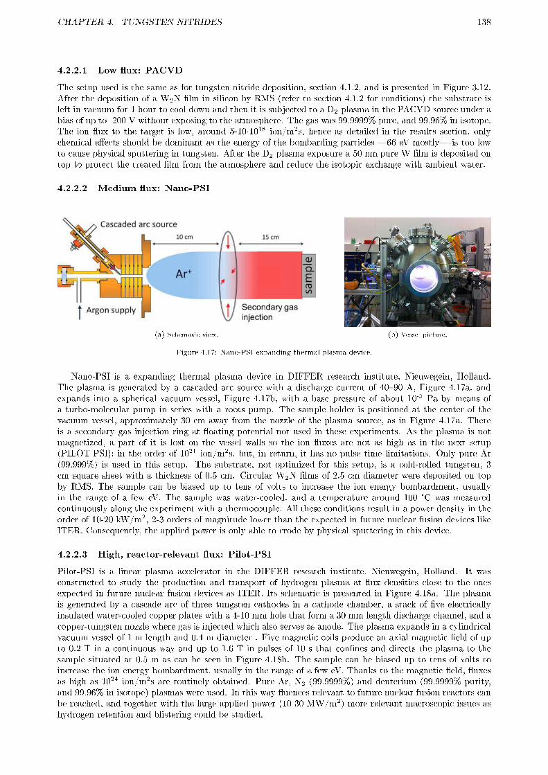
CHAPTER 4. TUNGSTEN NITRIDES 138
4.2.2.1 Low �ux: PACVD
The setup used is the same as for tungsten nitride deposition, section 4.1.2, and is presented in Figure 3.12.After the deposition of a W2N �lm in silicon by RMS (refer to section 4.1.2 for conditions) the substrate isleft in vacuum for 1 hour to cool down and then it is subjected to a D2 plasma in the PACVD source under abias of up to -200 V without exposing to the atmosphere. The gas was 99.9999% pure, and 99.96% in isotope.The ion �ux to the target is low, around 5-10·1018 ion/m2s, hence as detailed in the results section, onlychemical e�ects should be dominant as the energy of the bombarding particles �66 eV mostly� is too lowto cause physical sputtering in tungsten. After the D2 plasma exposure a 50 nm pure W �lm is deposited ontop to protect the treated �lm from the atmosphere and reduce the isotopic exchange with ambient water.
4.2.2.2 Medium �ux: Nano-PSI
(a) Schematic view. (b) Vessel picture.
Figure 4.17: Nano-PSI expanding thermal plasma device.
Nano-PSI is a expanding thermal plasma device in DIFFER research institute, Nieuwegein, Holland.The plasma is generated by a cascaded arc source with a discharge current of 40�90 A, Figure 4.17a, andexpands into a spherical vacuum vessel, Figure 4.17b, with a base pressure of about 10-5 Pa by means ofa turbo-molecular pump in series with a roots pump. The sample holder is positioned at the center of thevacuum vessel, approximately 30 cm away from the nozzle of the plasma source, as in Figure 4.17a. Thereis a secondary gas injection ring at �oating potential not used in these experiments. As the plasma is notmagnetized, a part of it is lost on the vessel walls so the ion �uxes are not as high as in the next setup(PILOT-PSI): in the order of 1021 ion/m2s, but, in return, it has no pulse time limitations. Only pure Ar(99.999%) is used in this setup. The substrate, not optimized for this setup, is a cold-rolled tungsten, 3cm square sheet with a thickness of 0.5 cm. Circular W2N �lms of 2.5 cm diameter were deposited on topby RMS. The sample can be biased up to tens of volts to increase the ion energy bombardment, usuallyin the range of a few eV. The sample was water-cooled, and a temperature around 100 °C was measuredcontinuously along the experiment with a thermocouple. All these conditions result in a power density in theorder of 10-20 kW/m2, 2-3 orders of magnitude lower than the expected in future nuclear fusion devices likeITER. Consequently, the applied power is only able to erode by physical sputtering in this device.
4.2.2.3 High, reactor-relevant �ux: Pilot-PSI
Pilot-PSI is a linear plasma accelerator in the DIFFER research institute, Nieuwegein, Holland. It wasconstructed to study the production and transport of hydrogen plasma at �ux densities close to the onesexpected in future nuclear fusion devices as ITER. Its schematic is presented in Figure 4.18a. The plasmais generated by a cascade arc of three tungsten cathodes in a cathode chamber, a stack of �ve electricallyinsulated water-cooled copper plates with a 4-10 mm hole that form a 30 mm length discharge channel, and acopper-tungsten nozzle where gas is injected which also serves as anode. The plasma expands in a cylindricalvacuum vessel of 1 m length and 0.4 m diameter . Five magnetic coils produce an axial magnetic �eld of upto 0.2 T in a continuous way and up to 1.6 T in pulses of 10 s that con�nes and directs the plasma to thesample situated at 0.5 m as can be seen in Figure 4.18b. The sample can be biased up to tens of volts toincrease the ion energy bombardment, usually in the range of a few eV. Thanks to the magnetic �eld, �uxesas high as 1024 ion/m2s are routinely obtained. Pure Ar, N2 (99.9999%) and deuterium (99.9999% purity,and 99.96% in isotope) plasmas were used. In this way �uences relevant to future nuclear fusion reactors canbe reached, and together with the large applied power (10-30 MW/m2) more relevant macroscopic issues ashydrogen retention and blistering could be studied.

CHAPTER 4. TUNGSTEN NITRIDES 139
(a) Schematic view. (b) Picture during plasma operation.
Figure 4.18: Pilot-PSI linear plasma accelerator.
Two mechanical booster pumps are operated in parallel to achieve an e�ective pumping speed of 7200m3/h to keep the vessel pressure at 0.1-1 Pa during plasma operation. The plasma (electron) temperatureand density are measured by Thomson Scattering close to the sample. The sample is water cooled at theback, but due to the huge heat loads the temperature at the back of the sample may be very di�erent from theexposed surface. Consequently, the temperature is measured by Infrared Thermography using the emissivityof the surface of the sample. However, no emissivity data were available for tungsten nitrides so the surfacetemperature is uncertain. Furthermore, the same tungsten substrates samples as in Nano-PSI with W2Nby RMS �lms on top were used, but their size is neither optimized for Pilot-PSI. Both issues caused thatthe temperature of the sample could not be measured in the most part of the experiments, and due to thenon-optimized size the temperature reached is very variable from one sample to another. This caused thatin some experiments the temperature were so high that the �lms were completely peeled o�. To avoid theseproblems and to compare with reactor in-situ nitridation, circular tungsten samples of 2.5 cm in diameterand 1 mm thick, optimized for their use in Pilot-PSI, were also tested.
4.2.3 Plasma exposure
4.2.3.1 Low �ux
To test for chemical reactions of deuterium with nitrogen a W2N �lm biased at -200 V was exposed afterits deposition to a pure D2 RF-plasma at a pressure of 2 Pa. The experiment lasted 1 h with a measuredmean ion �ux of 5·1018 ion/m2s. In laboratory cold plasmas at 2 Pa the ion distribution is a majority ofH3
+, with a 10-20% of H2+ and H+ [83], so a �uence of 5·1022 D/m2 can be derived as the distribution of H
and D ions will be very similar. The bombarding energy will be mostly 66 eV with a fraction of 100 eV and200 eV, so the expected penetration range is between 30 and 63 nm [186]. At these energies the W2N �lmshould not be physically eroded, as its sputtering threshold is estimated to be over 250 eV. Nevertheless, itwill be a�ected by chemical sputtering, i.e. a N preferential sputtering aided by a chemical reaction, mostprobably to form ammonia which desorbs from the surface [161]. The chemical sputtering is con�rmed byAES analysis, Figure 4.19a. Comparing the decrease of tungsten concentration with that of nitrogen in thepart a�ected by the plasma (at 40 min), the erosion thickness could be estimated. The nitrogen was removedin the initial 5.3 ± 0.8 nm, while the total thickness of the layer a�ected by the plasma (contaminated with Fefrom sputtering of the sample holder) was 12 ± 1 nm. These results are con�rmed by TEM in Figure 4.19b.It clearly shows the part a�ected by the plasma, white central part of about 5 nm, and what seems to besome di�usion or deeper implantation of lighter atoms (D and Fe) seen as white dots up to 15-20 nm fromthe protective tungsten layer.
4.2.3.2 Medium �ux
Thick W2N circular �lms on a square tungsten substrate were exposed in the NANO-PSI device to pure argonplasmas to test their physical sputtering compared to pure W. In Figure 4.20a the mask used to supportthe sample and to cover its lower part is shown. In this way a step is created for the W2N �lm and forW bare substrate part. Due to the erosion caused by argon and the low temperatures reached (about 100°C) no macroscopic e�ects on the �lms are expected. Two batches of samples were used, one 700 nm thicksample, and two 1500 nm thick ones. Each sample was exposed to an increasing negative bias �-70, -90 and-110 V� to compare with the sputtering yield calculated for pure tungsten by the empirical formula 4.1.

CHAPTER 4. TUNGSTEN NITRIDES 140
(a) AES depth pro�le. (b) Cross-section TEM.
Figure 4.19: W2N layer bombarded with D2 RF-plasma during 1 h at -200 V. After the bombardment a 50 nm W layer wasdeposited in situ on top to protect the bombarded area from atmosphere.
Unfortunately, it was later discovered that the thicker samples were deposited in an insu�cient depositionchamber conditioning (water and residual air). This caused a too high �lm contamination, poor adherenceand hence easy �aking.
(a) Holder with test sample. (b) 700 nm W2N, 9 min at -70 V. (c) 1500 nm W2N, 15 min at -90 V.
Figure 4.20: Tungsten square samples exposed to plasmas in Nano-PSI device at di�erent bias and exposure times
The 700 nm thick W2N �lm was exposed to a pure argon plasma at -70 V during 9 minutes in a holder as inFigure 4.20a. It showed no problem and the step created by the erosion is easily distinguished, Figure 4.20b.To compare the erosion of W and W2N the part of the W2N �lm closest to the W bare substrate wasmeasured in order to minimize the intrinsic inhomogeneity of the plasma beam. The measured erosion bypro�lometry was 190±40 nm for the W2N �lm and 355±40 nm for W. Three pro�les were taken for each partto improve statistics. Due to the complex sample holder shape, see Figure 4.20a, it is di�cult to estimatethe area exposed to the plasma, but it was around 12±2 cm2. In this way the plasma �ux and �uence areestimated as 2.1±0.5·1021 Ar/m2s and 1.1±0.3·1024 Ar/m2, respectively. At 70 eV Ar+ energy bombardmentthe tungsten sputtering yield calculated by equation 4.1 is 0.0159. The sputtering yield for W2N can beestimated using the ratio for W to W2N sputtering yield calculated by other authors using SRIM with 260eV argon ions: 0.78 [162]. At 70 eV Ar+ the W2N sputtering yield is estimated as 0.0124. The uncertaintyin the ion �ux causes the error of the estimated erosion to be very large. For pure tungsten the erosion is300±50 nm, in the order of the measured one but underestimating it, while for W2N is 234±39, overestimatingthe measured one, showing that SRIM code used did not simulate properly the W2N erosion (as the newSDTRIM.SP does [169]).
On the other hand, the 1500 nm thick �lm exposed to an argon plasma at -110 V during 8 min completely�ake o�, so no measurement was possible. The one exposed to an argon plasma at -90 V during 15 min�aked o� in the plasma-exposed W2N �lm closest to the mask, see Figure 4.20c. This made the pro�lometrymeasurement unreliable, but it points out to a W and W2N erosion of roughly 1100 and 600 nm, respectively.
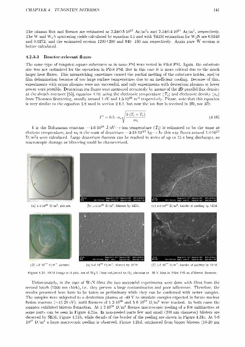
CHAPTER 4. TUNGSTEN NITRIDES 141
The plasma �ux and �uence are estimated as 2.3±0.5·1021 Ar/m2s and 2.1±0.4·1024 Ar/m2, respectively.The W and W2N sputtering yields calculated by equation 4.1 and with SRIM estimation for W2N are 0.0349and 0.0272, and the estimated erosion 1200±200 and 940±150 nm respectively. Again pure W erosion isbetter calculated.
4.2.3.3 Reactor-relevant �uxes
The same type of tungsten square substrates as in nano-PSI were tested in Pilot-PSI. Again, the substratesize was not optimized for the operation in Pilot-PSI. But in this case it is more critical due to the muchlarger heat �uxes. This mismatching sometimes caused the partial melting of the substrate holder, and/or�lm delamination because of too large surface temperatures due to an ine�cient cooling. Because of this,experiments with argon plasmas were not successful, and only experiments with deuterium plasmas at lowerpower were possible. Deuterium ion �uxes were measured accurately by means of the 2D parallel �ux densityat the sheath entrance [55], equation 4.10, using the electronic temperature (Te) and electronic density (ne)from Thomson Scattering, usually around 1 eV and 1.5·1020 m-3 respectively. Please, note that this equationis very similar to the equation 2.8 used in section 2.1.1, but now the ion �ux is received in 2D, not 3D:
Γ i = 0.5 · ne
√k (Ti + Te)
mi(4.10)
k is the Boltzmann constant �1.6·1019 J/eV�; ion temperature (Ti) is estimated to be the same aselectron temperature, and mi is the mass of deuterium �3.34·10-27 kg�. In this way �uxes around 1.4·1024
D/m2s were calculated. Large deuterium �uences can be reached in series of up to 75 s long discharges, somacroscopic damage as blistering could be characterized.
(a) 1-2·1026 D/m2, picture. (b) 1-2·1026 D/m2, blisters by SEM. (c) 1-2·1026 D/m2, border of peeling by SEM.
(d) 5-6 1027 D/m2, picture. (e) 5-6 1027 D/m2, blisters by SEM. (f) 5-6 1027 D/m2, border of peeling by SEM.
Figure 4.21: SEM image and pictures of W2N �lms subjected to D2 plasmas at -40 V bias in Pilot-PSI at di�erent �uences.
Unfortunately, in the case of W2N �lms the two successful experiments were done with �lms from thesecond batch (1500 nm thick), i.e. they present a large contamination and poor adherence. Therefore, theresults presented here have to be taken as preliminary while they can be con�rmed with newer samples.The samples were subjected to a deuterium plasma at -40 V to simulate energies expected in future nuclearfusion reactors (∼15-20 eV), until �uences of 1-2·1026 and 5-6 1027 D/m2 were reached. In both cases thesamples exhibited blisters formation. At 1-2·1026 D/m2 �uence macroscopic peeling of a few millimetres atsome parts can be seen in Figure 4.21a. In non-peeled parts few and small (200 nm diameter) blisters aredetected by SEM, Figure 4.21b, while details of the border of the peeling are shown in Figure 4.21c. At 5-61027 D/m2 a large macrocopic peeling is observed, Figure 4.21d, originated from bigger blisters (10-20 µm
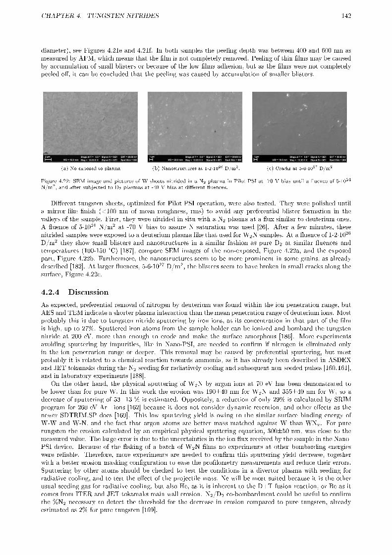
CHAPTER 4. TUNGSTEN NITRIDES 142
diameter), see Figures 4.21e and 4.21f. In both samples the peeling depth was between 400 and 600 nm asmeasured by AFM, which means that the �lm is not completely removed. Peeling of thin �lms may be causedby accumulation of small blisters or because of the low �lms adhesion, but as the �lms were not completelypeeled o�, it can be concluded that the peeling was caused by accumulation of smaller blisters.
(a) No exposed to plasma. (b) Nanostructures at 1-2·1026 D/m2. (c) Cracks at 5-6·1027 D/m2.
Figure 4.22: SEM image and pictures of W sheets nitrided in a N2 plasma in Pilot-PSI at -70 V bias until a �uence of 5·1024
N/m2, and after subjected to D2 plasmas at -40 V bias at di�erent �uences.
Di�erent tungsten sheets, optimized for Pilot-PSI operation, were also tested. They were polished untila mirror-like �nish (<100 nm of mean roughness, rms) to avoid any preferential blister formation in thevalleys of the sample. First, they were nitrided in situ with a N2 plasma at a �ux similar to deuterium ones.A �uence of 5·1024 N/m2 at -70 V bias to assure N saturation was used [26]. After a few minutes, thesenitrided samples were exposed to a deuterium plasma like that used for W2N samples. At a �uence of 1-2·1026
D/m2 they show small blisters and nanostructures in a similar fashion as pure D2 at similar �uences andtemperatures (100-150 °C) [187], compare SEM images of the non-exposed, Figure 4.22a, and the exposedpart, Figure 4.22b. Furthermore, the nanostructures seem to be more prominent in some grains, as alreadydescribed [182]. At larger �uences, 5-6·1027 D/m2, the blisters seem to have broken in small cracks along thesurface, Figure 4.22c.
4.2.4 Discussion
As expected, preferential removal of nitrogen by deuterium was found within the ion penetration range, butAES and TEM indicate a shorter plasma interaction than the mean penetration range of deuterium ions. Mostprobably this is due to tungsten nitride sputtering by iron ions, as its concentration in that part of the �lmis high, up to 27%. Sputtered iron atoms from the sample holder can be ionized and bombard the tungstennitride at 200 eV, more than enough to erode and make the surface amorphous [186]. More experimentsavoiding sputtering by impurities, like in Nano-PSI, are needed to con�rm if nitrogen is eliminated onlyin the ion penetration range or deeper. This removal may be caused by preferential sputtering, but mostprobably it is related to a chemical reaction towards ammonia, as it has already been described in ASDEXand JET tokamaks during the N2 seeding for radiatively cooling and subsequent non-seeded pulses [160,161],and in laboratory experiments [188].
On the other hand, the physical sputtering of W2N by argon ions at 70 eV has been demonstrated tobe lower than for pure W. In this work the erosion was 190±40 nm for W2N and 355±40 nm for W, so adecrease of sputtering of 53±13 % is estimated. Oppositely, a reduction of only 29% is calculated by SRIMprogram for 260 eV Ar+ ions [162] because it does not consider dynamic retention, and other e�ects as thenewer SDTRIM.SP does [169]. This low sputtering yield is owing to the similar surface binding energy ofW-W and W-N, and the fact that argon atoms are better mass matched against W than WNx. For puretungsten the erosion calculated by an empirical physical sputtering equation, 300±50 nm, was close to themeasured value. The large error is due to the uncertainties in the ion �ux received by the sample in the Nano-PSI device. Because of the �aking of a batch of W2N �lms no experiments at other bombarding energieswere reliable. Therefore, more experiments are needed to con�rm this sputtering yield decrease, togetherwith a better erosion masking con�guration to ease the pro�lometry measurements and reduce their errors.Sputtering by other atoms should be checked to test the conditions in a divertor plasma with seeding forradiative cooling, and to test the e�ect of the projectile mass. Ne will be most suited because it is the otherusual seeding gas for radiative cooling, but also He, as it is inherent to the D+T fusion reaction, or Be as itcomes from ITER and JET tokamaks main wall erosion. N2/D2 co-bombardment could be useful to con�rmthe %N2 necessary to detect the threshold for the decrease in erosion compared to pure tungsten, alreadyestimated as 2% for pure tungsten [169].

CHAPTER 4. TUNGSTEN NITRIDES 143
Some W2N samples were subjected to reactor-relevant �uxes of deuterium plasma. However, due to alarge contamination of those �lms the results obtained need to be con�rmed by new experiments. For thisreason no analysis of deuterium retention has been done in order to wait for �lms with lower contamination,as impurities are known to lead to larger D retention [128]. NRA and TDS analysis will be combined to beable to con�rm if the D retention in the bulk is enhanced, and if the total retention is increased as alreadydescribed for plasma nitriding of the surface [171, 175, 185]. Nevertheless, W2N can behave di�erently thanWNx obtained by ion bombardment.
Important surface blistering has been detected in W2N samples, but it also needs to be con�rmed. Thelarge contamination induces a larger blistering by increasing the number of traps and decreasing the deuteriumrecombination coe�cient, see T. Tanabe et al [128] and references therein. Consequently, it is very di�cultto distinguish if the tungsten nitride su�ers more blistering. At intermediate-high �uences, 1-2·1026 D/m2,some blisters and a special kind of nanostructures were also detected at some grains in polished tungstensheets exposed previously to a nitrogen plasma to saturate the surface. This is in agreement with the resultsdescribed by other authors for pure tungsten [182,187]. Furthermore, due to the relatively low temperature ofthese samples during the deuterium plasma exposition (100-150 °C), the blistering is not expected to increasedue to the implantation of nitrogen [185]. At very large �uences, 5-6·1027 D/m2, a large number of cracks isseen along the surface, with no grain preference, most probably caused by the plastic deformation and thetrapped deuterium release from blisters [128,183]. This step will be previous to macroscopic surface peeling,observed already at both �uences in W2N �lms, see Figure 4.21. This large di�erence in peeling threshold,as commented previously, will be caused by the large contamination of those samples. Notwithstanding, thethreshold is expected to be lower due to the already described nature of W2N as di�usion barrier [162�167],although other experiments indicate a lower deuterium retention for W2N [175], and hence, lower blistering.
4.2.5 Summary and future work
At present a large e�ort is being made in the fusion community towards the quanti�cation of the hydrogenisotopes retention of tungsten, due to the possible long term trapping of tritium, which could lead to animportant safety issue. This is specially critical for nitrogen, as it will be trapped in the tungsten surfaceduring nitrogen seeding for radiative cooling. First results from other authors point to a larger deuteriumretention in the bulk caused by the tungsten nitrides, although the mechanism is not clear: acting as adi�usion barrier for deuterium, and/or by reducing the deuterium recombination coe�cient and hence itsrelease. However, those analysis were done in nitrided tungsten by plasma or ion implantation, di�erent tothe polycrystalline W2N of this work, which may have a di�erent behavior.
The reduced sputtering yield by argon ions of W2N compared to pure tungsten has been con�rmed. Ina future nuclear fusion reactor the erosion of tungsten tiles will be governed by heavy impurities as argon.Therefore, if the reduced sputtering can be extrapolated to other typical impurities (He, Ne, B, Be, etc), itwould lead to a reduced erosion and lifetime increase of the tungsten tiles covered by thick W2N �lms. It hasalso been shown that deuterium plasma will remove selectively the nitrogen from the �lm. However, moreexperiments are needed to con�rm the depth of this selective removal, much larger than impurities erosionrange, and how it a�ects to the sputtering decrease. On the other hand, deuterium plasma loads on tungstenhave arisen another important issues, not from direct sputtering and erosion but because of blistering, thetritium retention in them, and subsequent dust formation at very large �uences. Experiments with plasma orion-implanted nitrogen by other authors point to a slightly larger blistering, while in the polycrystalline W2N�lms of this work blistering increase was found to be more critical. However, this blistering will be partiallyrelated to the large contamination found in those �lms, so new experiments are necessary to con�rm thisadverse e�ect in order to be able to balance it with the bene�cial reduced sputtering yield. Another issue,not studied in this work, related to nitrogen seeding and nitrides is the tritiated ammonia formation and itsaccumulation inside the vessel on the cryopumps.
As future work the following experiments are proposed:
� Repeat the experiments in Nano-PSI and Pilot-PSI with adequate substrates (circular) and improvedSDN samples and contamination-free W2N.
� Erosion by di�erent gaseous impurities as Ar, Ne and He should be addressed. In this case, nano-PSIwill be more suited thanks to the more adequate erosion velocity because of medium ion bombardment�uxes. Films should be deposited (and perhaps also eroded) with a mask to ease the pro�lometrymeasurements interpretation. A good mask would be a 3 mm wide line going through the center wherethe erosion will be maximum due to the plasma shape.
� Erosion of W2N and new SDN �lms by deuterium plasmas under ITER ELM-like �uxes should betested. This feature, ELM-like pulses, has recently been upgraded in Pilot-PSI by means of a capacitor

CHAPTER 4. TUNGSTEN NITRIDES 144
bank.
� Blistering �uence threshold should be con�rmed for both W2N and new SDN �lms in order to balancewith the reduced erosion.
� Deuterium retention should be analyzed in both types of �lms in Pilot-PSI by combination of NRA andTDS with many samples to improve statistics. Furthermore, the deuterium under W2N and SDN layerswith a thick pure W layer on top should be analyzed to elucidate if any or both types of tungsten actas di�usion barriers. This would allow its use to alleviate the tritium retention in the bulk of tungsteneven if tungsten nitrides are proven not to be suited to cover tungsten tiles because of blistering.
� Blistering and deuterium retention experiments should be done at 2-3 di�erent temperatures to accountfor the di�erent behavior already described by other authors. One of those temperatures should bearound 500 °C, the expected steady state surface temperature for divertor tiles at future nuclear fusiondevices as ITER.
� Nitrogen surface concentration and its preferential sputtering by deuterium plasma with di�erent con-centrations of nitrogen should be studied to be able to predict the erosion during nitrogen seedingexperiments. The percentage of nitrogen during plasma operation is uncertain as it will depend on thescenario, the necessity of large seeding to radiate or not, etc.
� Generation of ammonia by the erosion of nitrogen atoms by hydrogen isotopes should be quanti�ed.The production of tritiated ammonia has to be reduced as much as possible because it will be trappedat the cryopumps �increasing the in-vessel tritium retained levels�, and it has to be treated later inthe Tritium Recovery Plant.

Chapter 5
SUMMARY
Extensive research has been conducted through this thesis on the properties of two of the main plasma-facing material for current and future nuclear fusion devices: tungsten and carbon (for its use in the formof graphite, or Carbon Fiber Composites, CFC). The study has been focused in their main drawbacks: forcarbon materials, formation and elimination of the codeposits responsible for tritium retention, which shouldtherefore be controlled while minimizing the generation of deleterious products like tritiated water (seeglossary for details); for tungsten, plasma core contamination, long-term erosion of wall tiles and preliminarystudies of tritium retention at the surface. The research has been carried out in the basis of treatments withnitrogen compounds in the case of carbon materials, and the use of tungsten nitrides by plasma bombardmentor thin �lm coating on tungsten materials. A brief summary of each chapter of this thesis is provided hereafter:
Carbon codeposits formation
The formation of carbon codeposits with hydrogen is a very complex process involving many steps: fromthe direct erosion of a carbon material, formation of hydrocarbon radicals, their transport and subsequentformation of amorphous hydrogenated carbon �lms (a-C:H, see glossary), an easy re-erosion of those �lmsby the plasma, until the �nal re-deposition in areas with low or no ion bombardment (plasma-shadowed).This process depends completely on each nuclear fusion device and the speci�c orientation of its �rst walltiles (see glossary) with respect to the magnetic �eld lines. In a stellarator (see glossary) as TJ-II thecomplexity of the magnetic �elds becomes clear �rstly by the fact that methane produced from chemicalsputtering of a graphite bar inserted in the plasma edge is largely transported along the poloidal direction;and secondly, through the larger heat �ux received by the bar, and hence the larger methane production, whenit is inserted to recover the eroded carbon in the toroidal direction. Furthermore, two di�erent phases wereobserved depending on the surface temperature of the inserted graphite bar: at intermediate temperatureschemical sputtering prevails, while at low temperatures or above 1100 K physical sputtering is predominant.The distinct operation throughout both phases is very important in a nuclear fusion device in terms of tritiumretention: physical sputtering will develop carbon �lms of low hydrogen isotopes content close to the source;but chemical sputtering will result in the formation of H-rich a-C:H �lms at long distances, specially at remoteareas.
The study of the process of redeposition of carbon codeposit �lms is also important for optimizing theinhibition of those �lms by means of the scavenger technique, which consists in injecting certain gas moleculesthat will react with the �lm precursors: ions and radicals. The chemistry of the scavenger technique is verycomplex: in this thesis it has been demonstrated that the �nal products obtained and probably the �lm inhi-bition e�ciency, greatly depend on the surface composition of the reactor walls, on the vacuum conditioningof the chamber, and, to a lesser extent, on the connecting tubes for the detection, and subsequent pumpingout, of the products. A technique denominated Cryo-Trap Assisted Mass Spectrometry (CTAMS) was usedto separate the products by means of a liquid nitrogen cold �nger. Otherwise the mass cracking pattern ofboth products and reactants completely overlaps and renders the calculation of the relative concentration ofthe products almost impossible.
Thanks to the CTAMS technique it has been shown that the critical parameter for the type of productsobtained was the coating of the reactor walls. Totally di�erent products were obtained in stainless steels walls�NH3, CH3CN y C2H4 mainly�, than the ones produced in a-C:H coated (carbonized) walls �HCN y C2H2
as main products�. In general, more hydrocarbons (di�erent from methane) are obtained and almost noradical production was detected in the afterglow plasma with carbonized walls, in contrast to stainless steelwalls where a large number of radicals seem to be trapped in the liquid nitrogen cold �nger. Furthermore,during the �rst minutes of plasma operation in stainless steels walls, the oxygen released from the oxides
145

CHAPTER 5. SUMMARY 146
at the surface has an important e�ect on the yield of some products due to the scavenger action of theoxygen-related molecules (OH, NO, O, etc.). These oxygen-related molecules a�ect mainly the productionof hydrocarbons with more than two carbon atoms, and favor the production of NH3. The e�ect of thesemolecules was specially evident when a plasma was done in an unintentional, large residual humidity environ-ment in carbonized walls: the products changed completely and they become in fact quite similar to the onesobtained in stainless steel walls. This highlights the paramount role of a proper vacuum conditioning whenstudying plasma reactions or, in general, during Plasma-Enhanced Chemical Vapor Deposition (PECVD). Ina nuclear fusion device, humidity levels during operation are very low, so their in�uence will be very limited.However, in this thesis it has been demonstrated that depending on the divertor (see glossary) materials,the a-C:H �lm precursors may vary during each phase of the plasma discharge (initial limiter phase, H andL modes, etc.). Therefore, to avoid this e�ect of the plasma operation and to achieve the most e�cientinhibition, scavenger molecules must be injected in the plasma afterglow: i.e. in remote parts like under thedivertor cassettes, pumping ducts, etc. In this way the possibility of plasma core contamination is greatlyreduced, and as those parts are usually made from stainless steel, which seems to improve the ammonia pro-duction �the most e�cient scavenger molecule in previous studies�, the a-C:H �lm inhibition will be furtherenhanced. As previously commented, it is precisely at those locations where the most di�cult-to-eliminate,tritium-rich carbon codeposits will develop.
Carbon codeposits elimination
Carbon codeposits with trapped tritium may develop on plasma-wetted as well as on plasma-shadowed sur-faces. It is necessary to treat those codeposits to recover the fuel, but at the same time the generationof deleterious products has to be minimized: tritiated water, reactive dust, residual �lms that can easilytrap/absorb tritium again, etc. The e�ciency of such treatment depends on the nature of the carbon code-posits �soft or hard a-C:H�, the presence of impurities �specially getters like Be or B�, and mainly ontheir location, like in remote areas, as they are specially di�cult to access.
The most typical technique is the use of conditioning (cold) plasmas. They are based on the creationof speci�c species (ions and radicals) in the plasma, which react with the carbon codeposits into gaseousproducts, which are then pumped out. Their main limitation is the low e�ciency on surfaces not in directcontact with the plasma. This limitation is caused by the absence of ion bombardment, whose species arespecially reactive, and, additionally, leave open �and hence more reactive� bonds at the surface of thecodeposits, leading to a synergistic erosion with other reactive species. Only radicals with a low surface lossprobability coe�cient (β, see glossary) will be able to reach certain plasma-shadowed parts like castellationgaps. Therefore, conditioning plasmas should be tested and thus optimized for maximizing the production ofreactive radicals. In order to avoid the production of tritiated water, NH3-based plasmas have been studied,as they show similar erosion rates than oxygen ones. In the case of direct current (DC) plasmas, the erosionon open surfaces was very good, but in absence of ion bombardment (achieved at the experiment by applyinga positive bias to the sample) or in simulated gaps (like those in tiles castellations, see glossary) the erosionwas very low because of the poor radical yield of DC plasmas. On the other hand, microwave (MW) andradio-frequency (RF) plasmas presented a very large erosion due to radicals: NH·, or N2
*+ H· at largerpowers. Furthermore, their chemical eroding properties are evidenced by the large erosion rates obtainedwhen increasing the surface temperature: 20-40 nm/s and 1-7 nm/s erosion rates for MW and RF plasmasrespectively at 350 °C. Both types of plasmas are representative of the conditioning plasmas expected to beused in future nuclear fusion devices as ITER, although the e�ciency of MW-plasmas (ECRH) is expectedto be lower due to their large poloidal asymmetry.
Unlike plasma treatments, thermo-oxidation can eliminate all kinds of carbon codeposits in a fast, e�cientway even at remote parts. It consists on the baking of the full device in a reactive atmosphere at relativelylarge pressures (in the order of hundreds of Pascals). Furthermore, the reaction rate is proportional to thecodeposits thickness, since the reaction occurs throughout the complete volume of the codeposit, and is slightlydependent on the gas pressure. This highlights the importance of the codeposits porosity �usually veryhigh, specially those soft a-C:H at remote parts� for their removal rate. The maximum baking temperaturedepends greatly on the device design, and usually requires many days to be reached. At the divertor tiles thetemperature will usually be larger than at the main wall tiles or at remote parts. For this work, the designvalues for ITER have been considered, ranging from 200 to 350 °C. Two gases have been tested: O2 and NO2.Oxygen shows poor erosion at temperatures bellow 350 °C, and its hydrogen removal rate is much largerthan carbon one, so it could leave residual, reactive, carbon-rich deposits which can absorb tritium duringsubsequent plasma operation. On the other hand, NO2 presents a very fast erosion rate even at 275 °C and itse�ciency is similar for mixed codeposits including getters as boron, which decrease the erosion rate in othertechniques. It can be e�ective even at remote parts �usually colder� as its removal rate is large enoughat 200 °C already. Furthermore, NO2 reacts at the same velocity with hydrogen and with carbon (in fact it

CHAPTER 5. SUMMARY 147
seems to react initially faster with sp3-bonded carbon), so the possibility of residual, reactive, carbon-richdeposits is minimized. However, the main shortcoming is the large production of tritiated water. Therefore,if the nuclear fusion device was previously operated with tritium, thermo-oxidation should only be used afterother techniques like cold plasma in order to minimize the amount of codeposits to be eliminated. In thisway, ideally, only the codeposits at remote parts would need to be removed, where other techniques cannotreach.
Laser techniques are based on the application of photon beams to the carbon codeposits at speci�clocations, leading to the desorption of the fuel trapped at the surface or to the ablation of the codeposit atlarge laser energy density. Laser ablation has the advantage of a relatively fast removal rate and that thefuel is mostly released in the form of hydrogen molecule, so that the gas requires almost no post-treatment.However, apart from the necessary remote handling operation, its main drawback is the large productionof reactive dust. In order to decrease the dust yield, the use of reactive atmospheres of di�erent gases hasbeen tested. The �rst e�ect studied was gas pressure. At 50 kPa the dust yield seems to be just slightlyreduced, but the ablation rate decreases for a estimated factor of 16 for the more reactive gases tested,N2 and O2, since they absorb the infrared radiation of the laser. Moderate pressures, around 100 Pa, aretherefore recommended. On the other hand, the presence of reactive gases, mainly O2, has other bene�ts: theredeposition of evaporated material at the edges of the laser crater is suppressed; partial thermo-oxidationof the surface is expected, thus compensating the lower ablation rate due to gas pressure; and the produceddust will probably not have retained fuel, as the latter has been completely released from the surface throughthe thermo-oxidation in previous laser pulses (no hydrogen is detected in the laser-induced plasma plumeafter a few pulses). By means of a fast camera it was observed that the particles (i.e. dust) ejection lastedfor a few ms, and had a conical shape. Particles velocity depends on their size, but it is around 50-300 m/s.These particles were collected in an aerogel to maintain its integrity, and to allow for compositional analysisof individual particles. The particles had a �ake shape in the range of a few microns: most of them were1-2 µm thick and between 5 and 15 µm wide and long. It was also detected that the deuterium contentdecreased with the size of the particles, as they are more e�ciently heated by the laser, and in addition, theyare probably originated from a surface heated in previous laser pulses. Larger particles (>20 µm) probablycome from the periphery of the laser impact spot during initial pulses, since they have almost the initialhydrogen content.
Another local treatment (requiring remote handling as well) has been tested as a dust-free alternative tolaser: plasma torch. It is a novel technique where plasma is generated locally at the exit of a small cylinderchamber in an analogue way to plasma cutting tools. This plasma is applied directly to the codeposit �lms.The main advantage of this technique is the huge erosion rate obtained, estimated in the range of 24 µm/son open surfaces for pure N2 plasma. Small quantities of O2 can be added for increasing the erosion rates bya factor 3-4, but then tritiated water will be produced. Erosion in simulated castellation gaps is reduced byabout two orders of magnitude compared to open surfaces, but it is still acceptable for this location.
Integration of techniques for carbon codeposits control
No technique alone can solve tritium retention in carbon codeposits issue. On the one hand, �lm inhibitionby scavengers has to be limited to remote parts, as the erosion of carbon bulk tiles could be too large,besides, it would be impossible to suppress the formation of �lms throughout the vessel. On the other hand,thermo-oxidation is the sole technique able to eliminate most carbon codeposits in the entire vessel, butthen, the production of large amounts of tritiated water would be too dangerous to handle and to treat.Additionally, this technique is limited to long shutdowns due to the long time required to heat up the vesselwalls. Consequently, a combination of techniques aimed to reduce the amount of carbon codeposits �or theirtritium content�, and to eliminate them �in the form of into easy-to-treat-products� in di�erent schedulesduring the device operation/maintenance is necessary.
The scope of the guide given in this thesis is as general and device-independent as possible. It is notintended to be a complete or detailed study for the integration of techniques for tritium retention control,but rather to complement previous works on this matter. The �rst step done was the study of each techniqueavailable during device operation in order to give an estimation of its potential for tritium retention decrease.Afterwards, an integration of all techniques for tritium retention control was addressed for di�erent materialmixes on the �rst wall, estimating their compatibility and e�ciency for each material mix.
Finally, an example is given by applying the possible maintenance schedules on a future nuclear fusiondevice as ITER to control tritium retention while minimizing production of deleterious products like tritiatedwater. In this example, without any treatment, the in-vessel mobilizable tritium limit, 700 g, would bereached in approximately three months, whereas by means of the suggested integrated treatment scheme,it has been estimated that the device might be operated during more than two years without any several-months-long (annual) shutdown. Apart from di�erent techniques aimed to reduce tritium retention during
CHAPTER 5. SUMMARY 148
plasma pulse, like ending the discharge in pure D2, the best treatment will be cold plasma: D2 or He plasmascan be done between pulses, while more reactive gases mixtures (He or D2 with N2 , NH3, O2, NO2) willbe used for longer shutdowns, as nights or weekends, as they will need subsequent D2 and He plasmas toeliminate the N and O atoms absorbed at the surface. For very long shutdowns other techniques may be usedto eliminate certain types of codeposits, which cannot be removed through cold plasma techniques. For thickcodeposits, laser ablation or desorption (or plasma torch) could be used, and �nally, codeposits and residuesleft by other techniques, like those in remote parts, can be removed by thermo-oxidation.
Tungsten nitride coating
In current and future nuclear fusion devices tungsten is gradually replacing carbon due to its low tritiumretention, good thermal and mechanical properties, and low erosion by sputtering. However, some issuesneed yet to be solved, specially if tungsten is to be installed at the main wall (see glossary) as well: neutron-induced damage, surface melting, and erosion by sputtering and its subsequent contamination of the plasmacore. This last issue has been studied in this thesis based on the use of nitrogen compounds. During nitrogenseeding experiments at the divertor, a low in�ux of tungsten atoms to the plasma core and an overall plasmaperformance enhancement were observed. This e�ect seems to be caused by the development of tungstennitrides at the surface of tungsten tiles during those experiments. Since such �lms are only a few nanometersthick, they will be removed as soon as a few seconds have elapsed without nitrogen seeding, and also duringlarge ELMs, as those expected in future nuclear fusion devices. In order to maintain these good propertiesbrought by tungsten nitride �lms, a possible alternative is the coating of the tungsten tiles with thick �lms.Two options were studied: direct deposition of tungsten nitrides and plasma nitridation of tungsten �lms.
Direct deposition has been done by Reactive Magnetron Sputtering (RMS) of a pure tungsten target in anAr/N2 plasma. These kind of �lms have been studied by other authors as di�usion barriers for intermetallicconnections in microelectronics. In this thesis, pure, compact, polycristalline W2N �lms were obtained,as con�rmed by X-Ray Di�raction (XRD) and X-ray Photoelectron Spectroscopy (XPS). The crystallinityobtained was relatively high thanks to the optimized deposition chamber for low-stress tungsten �lms. These�lms can therefore be used for coating of tungsten tiles, as they can be grown at a good rate and presentgood adherence to silicon and tungsten substrates. On the other hand, in order to be able to obtain thick�lms by plasma nitridation, a process called Sequential Deposition and Nitriding (SDN) of tungsten �lms wasdeveloped. It consists in the sequential deposition of a few nm of W or W2N �lms followed by a nitridationin a N2 plasma for long times. The �lms thus created had a larger nitrogen content, up to N/W 0.6, butthe crystallinity was very poor and they were a mix of W2N and WN, as revealed through XRD, XPS andTransmission Electron Microscopy (TEM). However, a large contamination from oxygen and iron was foundin those �lms by means of Auger Electron Spectroscopy (AES), leading to low adherence to he substrate insome of them. An undesired multilayer structure was also detected in SDN �lms through AES and TEM,regardless of the initial thickness of the tungsten or W2N layer. Moreover, the deposition rate was very slowowing to the long duration of the plasma nitriding steps. All these facts preclude the use of these �lms forcoating tungsten tiles until they are solved. The mentioned contamination and low adherence are expectedto be solved in a new deposition chamber; the obtention of an homogeneous layer in a faster rate, though, isexpected to be much more di�cult.
Tungsten nitride erosion and deuterium retention
In the harsh conditions of a future nuclear fusion reactor �neutron irradiation, long operation times, etc�tungsten tiles can su�er from a limited lifetime in terms of erosion and tritium retention, in spite of havinga low sputtering yield and not developing codeposits as carbon or beryllium.
In a nuclear fusion device tungsten will su�er almost no erosion from the main plasma species �D, T,He� due to its low sputtering yield. Consequently, the erosion of tungsten tiles are caused by intrinsic orseeded impurities as Be, B, N, C, O, Ne, Ar, etc. Nitrogen has shown a much lower erosion than predictedbecause of its accumulation on the surface of tungsten in the form of tungsten nitrides. In the experimentsfor this thesis, thick W2N �lms deposited by RMS have been bombarded by 70 eV Ar+ at relatively high�uxes of 2.1±0.5·1021 ion/m2s in an expanding thermal plasma device: Nano-PSI. The measured erosion wasaround half than the one of pure tungsten. This lower erosion rate is caused by the poor mass-match ofargon with nitrogen, so the detected erosion decrease will not be so important for other lighter impurities.Furthermore, it has also been demonstrated that deuterium ion bombardment at energies slightly larger thanthose expected at the divertor �66 and 100 eV versus 10-30 eV� selectively removes the nitrogen from the�lm, and will hence reduce its bene�cial e�ect on the sputtering yield. However, more experiments are neededto con�rm the depth of this selective nitrogen removal and how it a�ects the sputtering decrease. It willalso be necessary to investigate how the nitrogen removal is reduced in the case of deuterium and nitrogen

CHAPTER 5. SUMMARY 149
co-bombardment as will occur during the nitrogen seeding operation. Therefore, the extrapolation of thereduced erosion by W2N to a nuclear fusion device is uncertain, as it will depend on the materials of the �rstwall, whether impurities are seeded during operation, etc., but the bene�ts are expected to justify furtherstudies.
In a future nuclear fusion device, the hydrogen isotopes bombardment �ux to the divertor tiles, speciallyat the strike points (see glossary), will be huge, in the order of 1024-25 ion/m2s. Such large �uxes origintwo linked processes: increased hydrogen isotopes retention in the bulk caused by defects created by ionbombardment, migration along the grains, etc.; and formation of bubbles at the sub-surface with subsequentblistering and macroscopic peeling leading to the production of large quantities of dust. Preliminary studieson the in�uence of tungsten nitrides on both processes have been conducted in this thesis in a linear plasmadevice able to reach the �uxes expected at the strike points of future nuclear fusion devices: PILOT-PSI.However, it was not possible to study the deuterium retention due to the large contamination found in thebatch of the W2N �lms used. The blistering of those �lms was very large, but this is probably related tothe large contamination of the �lms found, which is known to greatly increase the deuterium trapping anddecrease its recombination coe�cient at the surface. At experiments by other authors, tungsten nitride layersmade through plasma implantation have shown a larger deuterium retention in the bulk and a slight blisteringincrease. The mechanism for both e�ects is not clear: tungsten nitrides may act as a di�usion barrier fordeuterium, and/or may reduce the deuterium recombination coe�cient and hence its release. Nonetheless,the behavior of these kind of tungsten nitrides could di�er from the one of polycrystalline W2N of this thesis.Further experiments with tungsten nitrides are needed for being able to balance the reduced sputtering yieldand the possible increase in deuterium retention and blistering.
First wall material selection for future nuclear fusion devices
As it has been shown throughout this thesis, carbon materials are gradually being substituted by tungstenin most experimental nuclear fusion devices. The main reason for this change is the formation of codepositsbetween the eroded carbon and the nuclear fusion fuel, being tritium the main concern because of its radioac-tivity, danger to human health and scarcity. Notwithstanding, carbon materials have the great advantageof sublimation. During o�-normal large heat loads like giant type-I ELMs (see glossary) and non-mitigateddisruptions (see glossary), carbon materials directly evaporate and the produced vapor can absorb part ofthe incoming energy and, in this way, protect the bulk material. In contrast, metals like tungsten can meltat the surface, and due to the magnetic �elds and plasma pressure, the melt can move elsewhere and bridgecastellations, form protrusions, etc. Shallow melting seems not to be a problem in the short-term, but incase of severe melting, it can render the material unserviceable and hinder the device operation, or even leadto a non-planned device shutdown for replacing the damaged tiles. In the case of ITER, which will �nallystart with a full tungsten divertor, there is an important risk of tile melting during the �rst operation yearsuntil the most powerful o�-normal events are controlled. On the contrary, the operation with carbon tiles atthe strike points would allow to gain the experience needed to operate the device safely, and to predict andmitigate o�-normal events like disruptions and giant type-I ELMs. There are still important concerns aboutthe remaining carbon in the vessel after replacing the carbon tiles. This carbon that could not be eliminatedmight lead to larger tritium retention by codeposit formation even in the absence of carbon materials.
As shown in this thesis, a device like ITER could probably be operated safely with tritium if carbon tilesare installed at the strike points. The tritium retention in carbon codeposits can be controlled by means of anintegration of di�erent techniques during both plasma operation and maintenance periods. A general guidehas been given here, but a real scheme will imply a much more detailed study. Obviously, the operational costswould be larger, and the available routine operation time shorter than with operation with a full-tungstendivertor, since the latter requires almost no maintenance. This last point has already been demonstrated atthe JET tokamak (see glossary), where no glow discharge plasma is done prior to operation, between pulses,etc, like it has to be routinely performed in the rest of devices. In the case of ITER, part of the techniqueshere proposed will probably be used for treating beryllium codeposits with tritium, and tritium retained atthe surface of tungsten. In any case, the integrated treatment under operation with carbon-related materialsshould only be necessary in a worst-case scenario, where ITER could not be operated safely with tungstentiles at the strike points. Nonetheless, the scope of the results here shown should not be limited to ITER.Other current fusion devices like DIII-D tokamak will operate with carbon tiles in the next years, and newexperimental nuclear fusion devices like W7X stellarator and JT-60SA tokamak will also operate initiallywith carbon materials at the �rst wall. All these devices will eventually need to eliminate developed carboncodeposits developed for a better device operation (mainly plasma density control), or at least for controllingtheir formation at some speci�c places. Furthermore, in case those devices try to obtain the nuclear licenseto operate with tritium, the results here presented could be used as a guide for a safe operation of thesedevices.
CHAPTER 5. SUMMARY 150
For tungsten, the research in this thesis has been focused on increasing the lifetime of the tungsten tiles inITER, which have to last for ten years until the �rst year-long shutdown. If insight into plasma disruptionsis gained and they can be successfully predicted and thus mitigated, as well as ELMs power loads are keptin acceptable ranges, the lifetime of the tiles would then be limited by sputtering erosion through impurities.The �rst experiments from coating tungsten tiles with W2N �lms have shown an important decrease in thesputtering yield in argon. However, more experiments are needed to quantify this bene�cial e�ect and tobalance it with a possible increase in tritium retention in the bulk and surface blistering.
I would like to close by mentioning that for a real nuclear fusion device like DEMO with a very largeneutron �ux, choosing the materials becomes even more complex. Carbon materials are totally discarded,even though the problem is not the carbon codeposits, since the large wall temperatures �500-700 °C� will infact cause the tritium amount retained in them to be very small. The real barriers are caused by the neutron�ux: great decrease of electrical conductivity; large erosion rate because of Radiation Enhanced Sublimation(RES); and large swelling of the material, which could lead to catastrophic failure. On the other hand,tungsten has to withstand the huge heat and particle �uxes with a bearable melting and surface crackingof the material. Furthermore, the neutron-induced damage will lead to uncertain transmutation, muchincreased tritium bulk trapping, and very poor mechanical properties due to neutron-induced embrittlement(the ductile-to-brittle transition temperature is expected to be around of 800 °C). For these reasons, othermaterials, like low-activation stainless steel and liquid metals, are day by day becoming an alternative to thetraditional ones for their application at DEMO divertor.
Chapter 6
RESUMEN
Nota del autor: en este resumen se harán referencias a diversos términos y abreviaturas en inglés cuyade�nición se encuentra en el glosario. Dichos términos y abreviaturas se encuentran en los dos idiomas, inglésy español, pero ordenados alfabéticamente en inglés.
Antecedentes
El desarrollo de la humanidad está intrínsecamente unido a una mayor demanda de energía. Actualmente, paracubrir esta demanda se emplean, principalmente, combustibles fósiles. Sin embargo, su uso esta directamenterelacionado con el calentamiento global (con todos sus costes económicos y sociales aparejados) y su suministroestá asociado a fuertes tensiones geopolíticas debido a que sus reservas están concentradas en unos pocospaíses. Por ello, en los países desarrollados se está generando una tendencia hacia energías alternativasque no contribuyan al efecto invernadero y aseguren la independencia energética. Muy pocos países tienenla capacidad de generar toda la electricidad que necesitan a partir de energías renovables a causa de lavariabilidad inherente de las mismas. Esto se debe a que el sistema eléctrico necesita una cierta cantidadde producción eléctrica base constante en el tiempo para asegurar la demanda. La energía eléctrica basepuede proporcionarse con la energía nuclear, ya sea de �sión o de fusión. La energía nuclear de �sión tienecomo principales inconvenientes sus residuos altamente radiactivos y la posibilidad de accidentes que losliberen, como ya ha ocurrido en Chernobil y Fukushima (en ambos el diseño era antiguo y poco seguro, y elcomportamiento y formación de los operadores estuvo lejos de ser el ideal, pero todo ello demuestra que elriesgo no es nulo). Esos inconvenientes han llevado a un gran rechazo social hacia la energía nuclear de �sión.En cambio, la energía nuclear de fusión conlleva un número mucho menor de residuos de baja actividad,y su seguridad es mucho mayor debido a que, en caso de fallo, la reacción se para (pues necesita altastemperaturas) y el calor residual producido después de una parada de emergencia es además relativamentebajo. Sin embargo, su desarrollo ha sido muy lento debido a la complejidad tecnológica de controlar lasreacciones nucleares de fusión. La reacción nuclear más fácil de conseguir en la tierra, y por tanto la másestudiada, es la reacción entre dos isótopos del hidrógeno: deuterio y tritio.
21D +3
1 T →42 He (3.5MeV ) +1
0 n (14.1MeV )
El deuterio se puede obtener del agua a través de técnicas convencionales no muy costosas. Pero el tritioes un isótopo radioactivo de 12,3 años de vida media, por lo que se debe producir en la propia centralmediante una envoltura regeneradora con litio (denominada �blankets�, ver glosario). En dicha envoltura ellitio es transmutado por los neutrones producidos en la propia reacción de fusión generando tritio y helio. Sibien existen reacciones nucleares que no requieren tritio y producen un número menor (y en algunos casosnulo) de residuos radiactivos, D + D, D + 3He, or H +11B, tienen sin embargo una menor densidad depotencia y de velocidad de reacción, y requieren además temperaturas más altas. Las perspectivas de dichoscombustibles son puramente especulativas a día de hoy, pero en un futuro seguramente sean posibles. Existenmuchos diseños de reactores de fusión nuclear, aunque en todos ellos el objetivo es que el combustible alcancetemperaturas del orden de 150 millones de grados en forma de plasma maximizando el criterio de Lawson oproducto triple: tiempo de con�namiento por temperatura y densidad del plasma. Para ello el plasma debeser con�nado para reducir el contacto con la pared del reactor y por tanto evitar la neutralización de losiones de dicho plasma.
Dado que el plasma está compuesto de partículas cargadas, se puede con�nar mediante campos magné-ticos en una región del espacio, minimizando el contacto con las paredes y maximizando así el tiempo decon�namiento y la temperatura. En este tipo de reactores ya se ha demostrado que la fusión es posible:
151

CHAPTER 6. RESUMEN 152
en 1991 los tokamak TFTR (EE.UU.) y JET (Reino Unido) produjeron varios MW de energía mediante lareacción D+T, aunque la energía de calentamiento empleada en el plasma fue mayor, llegando a un ratioentre energía producida y consumida (Q) de 0,6 en JET. Hoy en día se está construyendo en el sur de Franciael tokamak ITER, un proyecto internacional donde se pretende alcanzar un ratio Q = 10.
Existen dos modelos principales de máquinas de con�namiento magnético: tokamak y stellarator. Ambostipos de reactores tienen una geometría toroidal para cerrar las líneas del campo magnético sobre sí mismas.Ambos también generan dicho campo magnético a lo largo del toroide mediante bobinas circulares concéntricasa la cámara de vacío. La diferencia principal estriba en la forma de generar el campo magnético poloidal queda estabilidad al con�namiento al hacer que las líneas de campo sean helicoidales. En los tokamak se utiliza untransformador central para inducir en el plasma una corriente toroidal muy alta que a su vez genera el campomagnético poloidal. Los stellarator utilizan en cambio bobinas externas para hacer que las líneas de campomagnético sean helicoidales. Ambos modelos se pueden observar en las Figuras 1.1 y 1.2 en la página 9. Lostokamak son el diseño más avanzado al ser más fácil de diseñar y construir, pero son más inestables debidoa que el propio plasma es utilizado para con�narse a sí mismo. Por ello se piensa en los stellarator como unaopción a largo plazo.
Para controlar la forma del plasma y que entre en contacto sólo con una parte de la pared se utilizan dosmétodos: limitadores y divertores, cuyos respectivos esquemas se muestran en la Figura 1.3 en la página 10.Un limitador es una pieza que sobresale de la pared, generalmente a lo largo de la dirección toroidal, limitandode esta manera el tamaño del plasma al volumen donde las lineas magnéticas no atraviesen el sólido, ya quelos iones se neutralizarían al entrar en contacto con él. Los limitadores sufren, no obstante, un �ujo de calory de partículas muy alto, los átomos del limitador que son erosionados pueden además entrar directamenteal plasma y contaminarlo. Por ello este diseño se ha abandonado en pos del divertor, más e�ciente, dondeunas bobinas secundarias instaladas en la parte inferior dirigen el plasma de salida (�exhaust�) hacia unaregión de la cámara de vacío optimizada para ello. En esta región el plasma es neutralizado en unas láminasde blindaje llamadas blancos (�target tiles�, ver glosario). Debido a su propio diseño se consiguen una seriede ventajas: gracias la (relativa) gran distancia con con respecto al plasma central, se reduce en gran medidala contaminación producida por los materiales de las paredes del divertor; el �ujo de calor hacia la pared seve asimismo reducido debido al intercambio de energía con los gases previamente neutralizados; es posibledirigir el �ujo de plasma para evitar que impacte siempre en el mismo punto, etc. Es más, gracias a la bajacontaminación del plasma central, en el divertor se puede inyectar intencionadamente impurezas gaseosaspara aumentar la radiación en esa región y así disminuir el �ujo de calor hacia los blancos.
En un reactor de fusión nuclear, los gradientes de temperatura entre el plasma y las paredes son losmayores conocidos por la humanidad. Esto hace que la interacción entre el plasma y la pared sea uno de losprocesos más importantes y estudiados. Además, el con�namiento del plasma y su interacción con la paredestán intrínsecamente unidos: cuando el plasma erosiona la pared, sus átomos pueden entrar en el plasmaenfriándolo por radiación y hacer que sea más inestable. Esas inestabilidades pueden provocar a su vez unmayor �ujo de partículas energéticas hacia la pared y que la erosión de la misma sea mayor, con lo quecomienza una reacción en cadena hacia la degradación del plasma. Como norma general, los átomos de mayornúmero atómico provocan una mayor pérdida de energía por radiación, y por lo tanto la posibilidad de causaruna inestabilidad es mayor. Por ese motivo dichos materiales deben ser situados en zonas como el divertor,donde la posibilidad de que uno de los átomos erosionados penetre en el plasma central es baja.
Existen muchos tipos de interacción del plasma con la pared, desde átomos de unos pocos electronvoltios(eV, ver glosario) que se escapan del con�namiento, hasta enormes �ujos de partículas y energía causadaspor diversos procesos como modos de borde (ELM por sus siglas en inglés, ver glosario) y disrupciones entokamaks (�disruptions�, ver glosario). Ambos procesos pueden llegar a fundir la super�cie de las paredesy provocar grandes daños en futuros reactores de fusión nuclear. En el caso de los ELM de tipo I, los másfrecuentes, la energía depositada en un reactor como ITER es de 8-20 MJ pero en un tiempo muy corto,0,1-1 ms, por lo que la densidad de potencia sería del orden de 1 GW/m2, más que su�ciente para fundir lasuper�cie de cualquier material. Por otra parte, las disrupciones pueden ser mucho más peligrosas, ya quela mayor parte de la energía del plasma central se deposita en estos casos en la pared, pudiendo llegar enITER a 10-150 GW/m2. Ambos procesos están siendo muy estudiados para reducir la energía depositada porellos y así disminuir los daños en el reactor. No obstante, además de lo anterior es necesario tener en cuentaque incluso en estado estacionario la potencia depositada en el divertor de ITER será muy alta, de variosMW/m2.
Cuando las partículas energéticas impactan en la pared trans�eren su momento a las átomos de dichapared provocando que puedan ser expulsados de ella mediante el proceso llamado pulverización física (�physicalsputtering�). La velocidad de erosión depende de muchos factores, como la energía de enlace de los átomosdel sólido, la masa del proyectil comparada con la del sólido, el ángulo de impacto, etc. En el caso de lafusión, como la mayor parte de los átomos son muy ligeros (isótopos del hidrógeno), a mayor masa atómica

CHAPTER 6. RESUMEN 153
de los átomos del blindaje de la pared, éste sufrirá una menor erosión pudiendo llegar a ser nula en casos dealta masa atómica y baja energía del proyectil (por ejemplo, el wolframio sólo es erosionado por átomos dedeuterio de más de 200 eV de energía). Por ello, en materiales de alta masa atómica, la velocidad de erosiónestá controlada por los contaminantes presentes en el plasma, como pueden ser átomos de oxígeno y nitrógenode las propias fugas de aire. Existe un caso de sinergia entre erosión química y pulverización física llamadopulverización química (�chemical sputtering�). Para determinados materiales, como es el caso de aquellosbasados en carbono, las partículas energéticas que bombardean la super�cie dejan enlaces libres que luegoreaccionan muy fácilmente con los átomos de hidrógeno formando moléculas volátiles (hidrocarburos en elcaso del carbono), que además vuelven a liberarse fácilmente debido al propio bombardeo. Esto provoca unagran velocidad de erosión de los materiales basados en carbono incluso a bajas energías de los proyectiles.Sin embargo, el mayor problema reside en que los hidrocarburos liberados interaccionan con las partículasdel plasma creando radicales e iones que se vuelven a depositar en la pared en forma de películas de carbonohidrogenado amorfo (a-C:H, ver glosario). Estas películas son a su vez erosionadas muy fácilmente por elplasma volviendo a comenzar el proceso hasta que son depositadas en zonas ocultas al plasma y ,por tanto,de bajo o nulo bombardeo iónico. En el caso de que la máquina utilice tritio, este proceso es muy grave, yaque una parte importante del tritio queda retenido en dichas películas. Por esta causa es de suma importanciacontrolar dichas películas, ya sea mediante su inhibición y/o su posterior tratamiento in-situ para recuperarel tritio. El tritio también puede quedar atrapado dentro de los sólidos mediante un proceso de implantacióny difusión debido al bombardeo del plasma. Sin embargo, en la mayor parte de materiales la retención dentrodel sólido es muy baja, por lo que no se espera que sea un problema (aunque, de serlo, la recuperación deltritio atrapado sería extraordinariamente compleja).
No existe un material perfecto que sea capaz de solventar todos estos problemas. Tradicionalmente enlos reactores experimentales de fusión nuclear se han usado materiales basados en carbono, debido a su bajacontaminación del plasma por su bajo número atómico, y a su gran capacidad de resistir altos �ujos de calor ypartículas ya que no se funden sino que subliman (además, el vapor producido en este caso absorbe una granparte de la energía incidente). Sin embargo, debido a la gran retención de tritio asociada a la formación decodepósitos de carbono con combustible nuclear, estos materiales están siendo desplazados por el wolframio.El wolframio es un material refractario de muy alto punto de fusión, alrededor de 3700 K, por lo que susprobabilidades de fundirse son relativamente reducidas. Su erosión es muy baja debido a su alto númeroatómico, y la contaminación del plasma es cada vez menor debido a los diseños mejorados de los divertores.Por otro lado, en el caso del wolframio es muy importante operar con inyección de impurezas en el divertorpara disminuir el �ujo de calor y la energía de los iones hacia la super�cie del sólido, especialmente en losblancos. Por todo lo anterior el wolframio ha sido elegido como el único material del divertor en el reactorITER.
Objetivos
A lo largo de esta tesis se han investigado las propiedades de los dos materiales de contacto con el plasma másusuales en máquinas experimentales de fusión nuclear tanto actuales como futuras: el wolframio o tungstenoy el carbón, ya sea en forma de gra�to o compuestos de �bra de carbono (CFC). El estudio se ha centradoen sus principales inconvenientes: para materiales basados en carbono se ha estudiado la formación y laposterior eliminación de los codepósitos responsables de la retención de tritio (un isótopo radiactivo delhidrógeno que forma parte del combustible nuclear), mientras se trata de evitar o reducir la generación deproductos residuales peligrosos como el agua tritiada (�tritiated water�, ver glosario para la explicación de supeligrosidad); en el caso del wolframio se ha investigado cómo minimizar la contaminación del plasma central,cómo reducir la erosión del blindaje de wolframio a largo plazo, y además se han realizado estudios preliminaressobre la retención de tritio en el interior del material. La investigación se ha basado en tratamientos concompuestos de nitrógeno en el caso de materiales basados en carbono, y en el uso de nitruros de wolframioformados mediante recubrimientos en capa delgada o mediante bombardeo con plasmas de nitrógeno. Losobjetivos detallados para cada apartado de la tesis son los siguientes:
1. Ver la in�uencia de los campos magnéticos en el transporte de los átomos de carbono erosionados deuna barra de gra�to insertada en el borde del plasma del stellarator TJ-II. Estudiar qué tipo de erosión,química o física, prevalece durante las distintas fases del experimento.
2. Analizar el origen de productos minoritarios de la técnica de neutralización (�scavenger�) para codepó-sitos de carbono y estudiar sus posibles implicaciones en la inyección de amoniaco en zonas remotas defuturos reactores nucleares de fusión como ITER.
3. Comparación de la erosión de codepósitos de carbono con plasmas de corriente continua de amonia-co realizados en nuestro laboratorio con otros tipos de plasmas en otros laboratorios como aquellos

CHAPTER 6. RESUMEN 154
generados por microondas y radiofrecuencias. Se compararán los plasmas atendiendo a sus diferentespropiedades, como la generación de un mayor número de especies tipo radicales o la mayor energía debombardeo de los iones.
4. Con�rmar y estimar la producción de agua en la oxidación térmica de codepósitos de carbono con NO2
y O2, y estudiar sus implicaciones para máquinas de fusión nuclear.
5. Estudiar la producción de polvo durante la ablación láser de un codepósito de carbono, y predecir susimplicaciones para un reactor de fusión nuclear, así como proponer técnicas para reducir su produccióncomo el uso de atmósferas reactivas. Extrapolación de los resultados a codepósitos de ITER con berilioy wolframio.
6. Estudiar la posibilidad de aplicar la técnica de antorcha de plasma para la eliminación de codepósitosde carbono en reactores de fusión nuclear. Investigar la in�uencia de tratamiento en atmósfera abiertao en el mismo gas reactivo de la antorcha de plasma.
7. Estudiar la integración de todas las técnicas de prevención y eliminación de codepósitos de carbonodentro de un esquema de mantenimiento para poder operar un futuro reactor de fusión nuclear conparedes de carbono. En este estudio se ha utilizado el esquema de mantenimiento propuesto para ITER
8. Depositar y caracterizar diferentes películas de nitruro de wolframio que puedan ser utilizadas dentrode un reactor de fusión nuclear como recubrimientos del blindaje del divertor.
9. Seleccionar las películas de nitruro de wolframio más adecuadas para posteriormente exponerlas a�ujos de plasma como los que se esperan en el divertor de un futuro reactor nuclear como ITER.Con�rmar la menor erosión de nitruros de wolframio respecto a wolframio puro y estudiar posiblesefectos adversos. Finalmente, estudiar la posibilidad de recubrir las láminas divertor de ITER connitruro de wolframio. Por último, relacionar la retención de nitrógeno en reactores actuales que operancon paredes de wolframio con la formación de nitruros de wolframio. Predecir qué tipo de película seformará y compararla con los que hemos producido nosotros.
Metodología
La metodología en el campo de la fusión nuclear se basa en una gran colaboración con otros laboratorios debidoa las grandes inversiones económicas requeridas y fomento de dicha colaboración �nanciando estancias porparte de la comunidad europea a través de Eurofusión y Euratom. En esta tesis se han utilizado diferentestécnicas de fabricación, tratamiento y de análisis de películas delgadas. La complejidad de muchos de losaparatos experimentales utilizados hace que sea complicado realizar un resumen exhaustivo y detallado decada uno. Para mayor detalle se ruega acudir al apartado correspondiente de la tesis. Estos son los aparatosutilizados:
� Stellarator TJ-II: es un dispositivo experimental de fusión nuclear tipo Heliac �exible. Su radio mayores de 1,5 m, y su radio menor 0,22 m (el interior de la cámara de vacío). El con�namiento magnéticose consigue mediante una serie de bobinas: 32 toroidales, que crean el campo magnético toroidal; dosbobinas centrales que proporcional el giro en tres dimensiones al plasma; y cuatro bobinas verticalesy radiales que que controlan la posición horizontal del plasma. Dispone de una gran cantidad de diag-nósticos para caracterizar el plasma, aunque en esta tesis sólo se utilizará Espectroscopía de EmisiónÓptica (OES) para comparar la señal del radical CH (precursor de la película de carbono) con el espesorde las películas recuperadas de la erosión de una barra de gra�to insertada en el plasma.
� Plasmas fríos: se han utilizado diferentes métodos para generar plasmas fríos tipo descarga luminiscente(�glow discharge�): por corriente continua (DC), por radiofrecuencias (RF) y por microondas (MW).Estos plasmas se han usado tanto para generar como eliminar películas de carbono hidrogenado amorfo,como para depositar películas de nitruro de wolframio mediante las técnicas de pulverización catódica(�sputtering�) y deposición química por vapor asistida por plasma (PACVD).
� Oxidación térmica: esta técnica consiste en la eliminación de codepósitos de carbono mediante sucalentamiento en una atmósfera reactiva de oxígeno o dióxido de nitrógeno a bajas presiones. Es unproceso análogo a la combustión, aunque en esta tesis el objetivo principal ha sido la medición de lavelocidad de erosión y los productos gaseosos y sólidos de dicho proceso.

CHAPTER 6. RESUMEN 155
� Ablación láser: consiste en la exposición de películas de carbono hidrogenado amorfo a haces energéticosde fotones (láser). En esta técnica la densidad de energía del haz es muy alta, por lo que se provocala destrucción del codepósito en forma de pequeñas partículas. Dichas partículas se han recogido enun tipo especial de aerogel de baja densidad para poder ser analizadas de forma directa sin ningúntratamiento que las altere. Se ha analizado tanto la distribución de tamaño de las partículas como sucomposición.
� Antorcha de plasma: es un dispositivo cilíndrico de pequeño tamaño donde se genera un plasma fríomediante radiofrecuencia en el interior. Mediante una pequeña abertura en la base se crea una antorchao �jet� de plasma muy reactivo de unos pocos centímetros de longitud. Esta técnica ha mostrado unagran velocidad de erosión de codepósitos de carbono y se ha utilizado para el estudio de la erosión dedichos codepósitos en lugares cerrados como las rendijas entre el blindaje de un dispositivo de fusiónnuclear.
� Nano-PSI: es un dispositivo de plasma termal expandido. El plasma se genera en una fuente de cascadade arco y se expande hacia la muestra en una cámara de vacío cilíndrica. Este dispositivo se ha utilizadopara comparar la erosión con un plasma de argón de películas de nitruro de wolframio con wolframiopuro. El objetivo es la con�rmación de la menor erosión física de láminas de blindaje de wolframiorecubiertas con películas de nitruro de wolframio.
� PILOT-PSI: es acelerador lineal de plasma de gran potencia. El plasma se genera en una fuente decascada de arco y se dirige y con�na mediante 5 bobinas magnéticas hacia la muestra. Se ha usadopara exponer muestras de nitruro de wolframio a �ujos y energías de plasma de deuterio comparablesa los de un futuro reactor nuclear de fusión como ITER. Se ha estudiado tanto la erosión física comola erosión química de los átomos de nitrógeno de la película.
Además de la deposición de películas delgadas por plasma también se han utilizado una gran cantidad detécnicas experimentales para analizar dichas películas, antes y después de los diversos tratamientos, y susproductos gaseosos (eliminación de codepósitos o exposición a plasmas que simulan los de un futuro reactornuclear). Ese conjunto de técnicas son:
� AES: Espectroscopía por Electrones Auger.
� EDX: Fluorescencia de rayos X por Energía Dispersiva.
� LIBS: Espectroscopía de Plasma Inducido por Láser.
� NRA: Análisis por Reacciones Nucleares Pro�lometría.
� RGA: Espectrometría Gaseosa de Masas.
� SEM: Microscopía Electrónica de Barrido.
� TDS: Espectroscopía de Desorción Térmica.
� TEM: Microscopía de electrónica de transmisión.
� XPS: Espectroscopía de fotoelectrones por rayos X.
� XRD: Difracción de Rayos X. RGA
Resultados
Formación de codepósitos de carbono
La formación de codepósitos de carbono con hidrógeno es un proceso muy complejo que consiste en variospasos: la erosión directa del material basado en carbono; la formación de hidrocarburos radicálicos; su trans-porte y la formación de películas de carbono hidrogenado amorfo; la fácil re-erosion de dichas películas por elplasma volviendo a comenzar el proceso anterior; y �nalmente, la redeposición de dichas películas en zonasde bajo o nulo bombardeo iónico (ocultas al plasma). Este proceso depende por completo de las caracterís-ticas de cada máquina de fusión nuclear y de la orientación de las laminas de blindaje de la primera pared(��rst wall�, ver glosario) con respecto a las líneas de campo magnético durante cada pulso de plasma. Enun stellarator como TJ-II, los campos magnéticos son muy complejos, como se ha demostrado en esta tesiscon la observación de un mayor transporte a lo largo de la dirección poloidal del metano producido por la

CHAPTER 6. RESUMEN 156
pulverización química de una barra de gra�to insertada en el borde del plasma. Esta complejidad también esevidente en el mayor �ujo de calor recibido por dicha barra, y por tanto la mayor producción de metano porpulverización química cuando la barra se inserta orientada para recoger el carbono erosionado en la direccióntoroidal. Además, se observan dos fases diferentes dependiendo de la temperatura de la super�cie de la barra:a temperaturas intermedias, entre 700-1100 K, predomina la pulverización química; mientras que en el restode temperaturas la pulverización física es mayor. La distinción entre ambas fases es muy importante de caraa la retención de tritio en una máquina de fusión nuclear: la pulverización física creará películas con un conte-nido bajo en codepósitos de carbono a distancias cercanas a la fuente; mientras que la pulverización químicaes la responsable de la formación de codepósitos de carbono (a-C:H) con una gran cantidad de isótopos dehidrógeno a larga distancia, especialmente en partes remotas de la máquina.
El estudio del proceso de la deposición de codepósitos de carbono es importante para la optimización de lainhibición de dichas películas mediante la técnica de neutralizadores (�scavengers�). Esta técnica consiste en lainyección de unas determinadas moléculas gaseosas que reaccionan con las moléculas precursoras de la películade carbono, ya sean iones y/o radicales, hacia moléculas estables que no originan películas. Las reaccionesde la técnica de neutralización son muy complejas. En esta tesis se ha demostrado que los productos �nalesobtenidos, así como la e�ciencia de la neutralización, dependen enormemente de la composición super�cialde la pared del reactor, del acondicionamiento de la cámara de vacío y, en menor medida, de los tubos deconexión para la detección de los productos mediante espectrometría de masas por bombeo diferencial. Paraseparar la señal medida de los productos se ha utilizado una técnica denominada espectrometría de masasasistida por trampa criogénica (CTAMS por sus siglas en inglés). Esta técnica consiste en la condensación departe de los productos en un dedo frío de nitrógeno líquido y su posterior evaporación secuencial una vez elplasma se ha detenido. De no realizarse así, la distribución del fraccionamiento de masas de cada productoaparecería completamente solapada en el espectrómetro con el resto y sería prácticamente imposible calcularla concentración relativa de dichos productos.
Gracias a la técnica CTAMS se ha demostrado que el parámetro crítico en el proceso de neutralización esel estado químico de las paredes del reactor. Se han obtenido productos totalmente diferentes en función desi las paredes eran de acero inoxidable (NH3, CH3CN y C2H4 principalmente); o si estaban recubiertas poruna película de a-C:H depositada con anterioridad (paredes carbonizadas, en cuyo caso se obtiene mayori-tariamente HCN y C2H2). En general, cuando las paredes están carbonizadas se obtiene un mayor númerode hidrocarburos (diferentes al metano) y casi no se detecta producción de radicales en la estela del plasma(�afterglow�). Por el contrario, cuando las paredes son de acero inoxidable, parece ser que una gran cantidadde radicales quedan atrapados en el dedo frío de nitrógeno líquido. Además, durante los primeros minutosdel plasma en paredes de acero inoxidable, el oxígeno emitido desde la capa de óxido super�cial de la paredtiene un importante efecto en los productos creados debido a la acción de neutralización de las moléculas conoxígeno (OH, NO, O, etc.) sobre ciertos radicales de hidrocarburos. Esas moléculas con oxígeno afectan ma-yoritariamente a la producción de hidrocarburos de más de dos carbonos, y favorecen a la vez la producciónde amoniaco. Resultan además especialmente críticas cuando el plasma se realiza en paredes carbonizadascon un contenido en humedad residual muy alto. En ese caso los productos creados son totalmente diferentesa humedad baja, y de hecho son muy similares a los obtenidos en paredes de acero inoxidable (NH3, CH3CN,etc.). Este hecho resalta la gran importancia de un adecuado acondicionamiento de la cámara de vacío cuandose pretende estudiar las reacciones del plasma, y en general durante la deposición por vapor químico ayudadopor plasma (PECVD por sus siglas en inglés). En una máquina de fusión nuclear, los niveles de humedaddurante su funcionamiento son muy bajos, por lo que éstas reacciones no deberían ser un problema. Porotro lado, en esta tesis se ha demostrado que, dependiendo de los materiales del divertor, los precursoresde la película de a-C:H pueden ser muy diferentes, y además pueden variar durante las distintas fases dela descarga (inicio en fase limitador, modo H o modo L, etc.). Por lo tanto, la inhibición será más e�cientecuando se inyecten los neutralizadores en la estela del plasma del divertor, es decir, en zonas remotas comodebajo del blindaje del divertor, tuberías de bombeo, etc. De esta manera las posibilidades de contaminarel plasma central y de erosionar el blindaje de carbono son mucho menores, y dado que esas partes remotasestán hechas de acero inoxidable, la formación de amoniaco, la mejor molécula neutralizadora encontrada, seespera que sea más alta y favorezca una mayor inhibición de películas de a-C:H. Es precisamente en dichasáreas donde se espera la formación de películas de a-C:H con un alto contenido en isótopos de hidrógeno, queadicionalmente son muy difíciles de tratar por los tratamientos habituales de eliminación.
Eliminación de codepósitos de carbono
Los codepósitos de carbono con isótopos de hidrógeno se pueden formar en partes expuestas al plasma uocultas a él. Se hace, por tanto, necesario el tratamiento de dichos codepósitos para recuperar el combustiblenuclear, si bien al mismo tiempo se debe evitar la creación de productos nocivos: agua tritiada, polvo reactivo,películas residuales que puedan atrapar o absorber tritio de nuevo, etc. La e�cacia de dichos tratamientos

CHAPTER 6. RESUMEN 157
depende de la naturaleza de los codepósitos de carbono (si son duros o blandos, ver entrada de a-C:H en elglosario), de la presencia de impurezas, especialmente atrapadores (�getters�) como B y Be, y principalmentede su localización, ya que la eliminación de los codepósitos en zonas remotas de la máquina es muy compleja.La técnica más típica es el uso de plasmas de acondicionamiento o plasmas fríos. Esta técnica se basa en lacreación en el plasma de especies especí�cas (iones y radicales) que reaccionan con los codepósitos de carbonoformando productos gaseosos que pueden ser extraídos fuera de la máquina de fusión nuclear. La principallimitación de esta técnica es su baja efectividad en zonas que no estén en contacto directo con el plasma.Esta limitación es causada por la ausencia de bombardeo iónico, cuyas especies son especialmente reactivas,y además inducen un gran número de enlaces abiertos y por ello más reactivos en los átomos de la super�cie,los cuales reaccionan de manera sinérgica con otras especies para favorecer la erosión. Solamente los radicalescon una probabilidad de pérdida en super�cie relativamente baja (β, �surface loss probability�, ver glosario)pueden llegar a ciertas partes ocultas al plasma, pero cercanas a éste, como las rendijas de las castelaciones(�castellations�, ver glosario) del blindaje de la primera pared. Por lo tanto, es necesario optimizar los plasmasde acondicionamiento para maximizar la creación de radicales. Para evitar la producción de agua tritiada sehan estudiado plasmas de amoniaco, que han mostrado velocidades de erosión similares a plasmas de oxígenoen super�cies expuestas al plasma. En el caso de plasmas de corriente continua ("DC-plasmas"), la erosiónen super�cies expuestas era aceptable, pero la erosión era muy baja en ausencia de bombardeo iónico (lo cualse reprodujo aplicando un potencial positivo a la muestra para repeler los cationes) o en rendijas construidasespecí�camente para tal �n. Esto se debe a la baja creación de radicales en ese tipo de plasmas. Por otro lado,en plasmas por microondas (�MW-plasmas�) o por radiofrecuencia (�RF-plasmas�) se encontraron velocidadesde erosión muy altas asociadas a radicales NH·, o a moléculas de nitrógeno activado (N2*) y H· a potenciasmayores del plasma. Además, se ha demostrado la naturaleza química de esta erosión por el incremento delas velocidades de erosión obtenidas al aumentar la temperatura de la película de a-C:H hasta 350 °C: 20-40nm/s y 1-7 nm/s para plasmas por microondas y radiofrecuencia respectivamente. Ambos tipos de plasmason representativos de los plasmas de acondicionamiento que se usarán en futuras máquinas de fusión nuclearcomo ITER, aunque la e�ciencia de los plasmas por microondas (asociados al calentamiento electrónico,ECRH) se espera que sea mucho menor debido a la gran asimetría poloidal que se ha encontrado en lasmáquinas actuales.
Al contrario que los tratamientos mediante plasmas fríos, la termo-oxidación puede eliminar todo tipode películas de carbono de manera rápida y es e�ciente incluso en áreas remotas. Esta técnica consiste enel calentamiento de toda la máquina en una atmósfera reactiva a presiones relativamente altas (centenas dePascales). La velocidad de reacción es proporcional al espesor de los codepósitos porque la termo-oxidaciónes una reacción en volumen, y además es ligeramente dependiente de la presión. Esto resalta la importanciade la porosidad de los codepósitos para la velocidad de su eliminación. Los codepósitos en zonas remotas sonde tipo blando, es decir muy porosos y reactivos, por lo que su velocidad de termo-oxidación es muy alta. Latemperatura máxima que pueden alcanzar en general los codepósitos depende completamente del diseño dela máquina de fusión nuclear, y normalmente requiere una parada de mantenimiento durante varios días paraalcanzarla. Debido al mejor intercambio térmico con el circuito refrigerante (que se usa habitualmente paraacondicionar) instalado en el blindaje del divertor, la temperatura en esta zona suele ser mayor que en elresto del blindaje de primera pared y en zonas remotas. En esta tesis se han utilizado los valores de diseño deITER, desde 200 °C en zonas remotas, hasta 350 °C en el blindaje del divertor, y se han investigado dos gases:O2 y NO2. El oxígeno muestra una erosión muy baja a temperaturas inferiores a 350 °C, y su velocidad deeliminación de hidrógeno es además mucho mayor que la del carbono, por lo que puede dejar residuos reactivosricos en carbono que pueden absorber tritio durante la siguiente fase de funcionamiento con plasma. Por otrolado, el dióxido de nitrógeno presenta una muy alta velocidad de erosión incluso a 275 °C, y su e�cienciaes similar para codepósitos mixtos incluso con atrapadores como boro, que en otras técnicas disminuye lavelocidad de reacción. Esta técnica puede ser efectiva incluso en zonas remotas, a menor temperatura, debidoa que la velocidad de erosión a 200 °C es su�cientemente alta para eliminar los codepósitos típicos en esaszonas. Es más, el NO2 reacciona a la misma velocidad con hidrógeno y con carbono (de hecho en los primerosmomentos parece que reacciona a mayor velocidad con carbono con enlace sp3), por lo que la posibilidad dedejar residuos reactivos ricos en carbono es mínima. Sin embargo, el gran inconveniente de esta técnica esla alta producción de agua tritiada. Por ello resulta necesario utilizar otras técnicas como plasmas fríos queminimicen la cantidad de codepósitos (o de tritio atrapado en ellos) que deba eliminarse por termo-oxidación.Idealmente, sólo se deberían eliminar los codepósitos de zonas remotas, que no puedan eliminarse por ningunaotra técnica.
Las técnicas por láser están basadas en la aplicación de haces de fotones a codepósitos de carbono en zonasespecí�cas induciendo la desorción de los isótopos de hidrógeno atrapados en su super�cie o provocando laablación del codepósito si la densidad energética del haz es su�cientemente alta. La ablación por láser presentala ventaja de una rápida eliminación del codepósito y que los isótopos de hidrógeno se recuperan en su forma

CHAPTER 6. RESUMEN 158
molecular, por lo que el tratamiento posterior necesario para recuperar el tritio sería muy bajo. Sin embargo,su mayor desventaja, aparte de la necesaria operación por brazo remoto, es la gran producción de polvoreactivo. Para disminuir la producción de polvo se ha investigado el uso de atmósferas reactivas. El primerefecto estudiado ha sido el debido a la presión de gas. A 50 kPa el polvo emitido parece ser menor, pero seestima que la velocidad de ablación del codepósito disminuye un factor 16 para los gases más reactivos, N2 yO2, debido a su absorción en el infrarrojo de la energía del láser. Por lo tanto se recomienda el uso de presionesmás moderadas, alrededor de 100 Pa. Por otro lado, la presencia de gases reactivos, especialmente O2, muestrabene�cios adicionales: inhibe la redeposición de material evaporado alrededor del cráter; la super�cie resultaparcialmente termo-oxidada, lo cual puede compensar la menor velocidad de ablación debido a la presióndel gas; y, �nalmente, con toda probabilidad el polvo generado no tendrá hidrógeno retenido debido a latermo-oxidación de la super�cie del codepósito (casi no se detecta hidrógeno en el plasma generado por elláser después de 2-3 pulsos). Por medio de una cámara rápida se ha observado que la emisión de polvo seproduce durante varios milisegundos y que además tiene forma cónica. La velocidad del polvo depende de sutamaño y se sitúa alrededor de 50-300 m/s. En algunos experimentos se atrapó el polvo en un aerogel paramantener su integridad, y también para permitir el análisis de partículas individuales. El polvo generadotiene forma de pequeñas láminas (��akes�) de unas pocas micras. La mayor parte de las partículas tienenun espesor de 1-2 µm y entre 5 y 15 µm de ancho y largo. Cuanto más pequeñas son las partículas, menores su contenido en hidrógeno residual debido a que han sido más e�cientemente calentadas por el láser, ymayor es la probabilidad de que provengan de una parte del codepósito calentado en anteriores pulsos delláser, es decir, de la zona central de impacto del láser. Asimismo, las partículas de mayor tamaño, >20 µm,probablemente provienen de la periferia del impacto del láser en los primeros pulsos debido a que contienenprácticamente la cantidad inicial de hidrógeno del codepósito.
Otro tratamiento local (requiere por tanto manipulación por brazo remoto) ha sido investigado comoalternativa al láser pero libre de generación de polvo: la antorcha de plasma. Se trata de una nueva técnicadonde el plasma es generado localmente a la salida de una pequeña cámara cilíndrica de modo análogo alas máquinas cortadoras por plasma. Este plasma es aplicado directamente a los codepósitos de carbono. Laprincipal ventaja de esta técnica son las grandes velocidades de erosión obtenidas, estimadas alrededor de24 µm/s en super�cies abiertas con un plasma de N2 puro. Pueden añadirse pequeñas cantidades de oxígenopara incrementar en un factor 3-4 las velocidades de erosión, pero entonces se podrían producir cantidadesapreciables de agua tritiada. La velocidad de erosión en rendijas se reduce alrededor de 2 órdenes de magnitudcon respecto a las super�cies abiertas, pero sigue siendo su�cientemente alta para esa localización.
Integración de técnicas para el control de codepósitos de carbono
Ninguna técnica puede por sí misma resolver el problema de la retención de tritio en codepósitos de carbono.Por un lado, la inhibición de la formación de codepósitos por neutralización se ha de limitar a zonas remotas,ya que la erosión de las láminas de blindaje de gra�to puede ser demasiado alta, y sería además imposibleoptimizar la inyección de neutralizadores para inhibir la formación de codepósitos en toda la cámara de vacío.Por otro lado, la única técnica capaz de eliminar la mayor parte de los codepósitos a lo largo de toda unamáquina de fusión nuclear es la termo-oxidación, pero generaría unas excesivas cantidades de agua tritiada,cuyo tratamiento y manejo sería tan peligroso como costoso. Además, dicha técnica está limitada a paradas demantenimiento de larga duración (varios días) a causa del tiempo necesario para calentar todas las paredes dela cámara. Por lo tanto, se hace necesaria una combinación de diferentes técnicas y su integración en los ciclosde funcionamiento y mantenimiento de la máquina de fusión nuclear. Estas técnicas deben estar orientadas areducir la formación de codepósitos de carbono, o reducir su contenido en tritio, y a su posterior eliminaciónen productos de fácil tratamiento.
El objetivo de la guía proporcionada en esta tesis ha sido dar unos parámetros que sean, en la medida de loposible, generales e independientes de cada máquina. No se ha intentado hacer un estudio completo o detalladode la integración de las técnicas para el control de la retención de tritio, sino más bien un complemento a lostrabajos anteriores sobre este tema. Por ello, el primer paso ha sido analizar la disponibilidad de cada técnicaa lo largo de los ciclos de funcionamiento y mantenimiento, y dar así una estimación de su potencial para ladisminución de la retención de tritio. Posteriormente, se ha realizado una integración de todas las técnicasde control de la retención de tritio, así como su compatibilidad y e�ciencia, según diferentes combinacionesde materiales en la primera pared. Finalmente, se ha proporcionado un ejemplo para un futuro reactor defusión nuclear como ITER aplicando diferentes técnicas dentro de sus posibles ciclos de funcionamiento ymantenimiento, a la vez que se ha intentado minimizar la producción de productos nocivos como agua tritiada.Sin ningún tratamiento, el límite de tritio movilizable dentro de la cámara de vacío (700 g) se alcanzaría enunos tres meses, mientras que con un tratamiento integrado se ha estimado que la máquina podría operardurante más de dos años sin que fuese necesaria ninguna parada de mantenimiento de larga duración (variassemanas o meses). Aparte de las técnicas para reducir el tritio retenido durante el pulso, como terminar la

CHAPTER 6. RESUMEN 159
descarga de plasma en D2 puro, el mejor tratamiento sería el plasma frío. A diario, entre pulsos se podríanhacer plasmas de D2 y/o He, mientras que el uso de gases más reactivos (He o D2 con N2, NH3, O2 y NO2) selimitaría a paradas de mayor duración como las noches y los �nes de semana, debido a que requieren plasmasde D2 y He para eliminar los átomos de nitrógeno y oxígeno absorbidos en la super�cie (principalmente en losatrapadores como Be, B, etc). Durante las paradas de larga duración (del orden de semanas) se pueden usarotras técnicas que adecuadas para eliminar ciertos tipos de codepósitos que no puedan eliminarse medianteplasma frío. Para codepósitos de gran espesor se puede usar ablación o desorción por láser, o antorcha deplasma, y �nalmente, la termo-oxidación con O2 o NO2 eliminaría el resto de codepósitos que no hayan podidoser tratados por las técnicas anteriores (como aquellos en zonas remotas) y los residuos dejados por ellas.
Recubrimiento de nitruro de wolframio
El wolframio está remplazando de forma gradual a los materiales basados en carbono en las máquinas de fusiónnuclear actuales y futuras debido a su baja retención de tritio, sus buenas propiedades mecánicas y térmicas,y su baja erosión por pulverización. Sin embargo, es necesario resolver aún algunas cuestiones, especialmentesi se desea emplearlo en la pared principal (�main wall�, ver glosario): daño inducido por neutrones, lo cualconduce a una mayor retención de tritio, fragilización, transmutación, etc.; posibilidad de que la super�ciese funda cuando está sometida a altas cargas térmicas; y contaminación del plasma central por parte delos átomos erosionados por pulverización debido a su alto número atómico. En esta tesis se ha estudiadoreducir el efecto de este último problema mediante el uso de compuestos nitrogenados: nitruros de wolframio.El desarrollo de nitruros de wolframio en la super�cie de las paredes de wolframio durante la inyección denitrógeno en el divertor parece ser el responsable del menor �ujo de átomos de wolframio al plasma central,y también de una mejora general de los parámetros del plasma en algunas máquinas de fusión nuclear. Sinembargo, como dichas películas sólo tienen un espesor de unos pocos nanómetros desaparecerán despuésde unos segundos sin inyección de nitrógeno y también por ELMs de gran tamaño, como los esperados enfuturas máquinas de fusión nuclear. Para mantener los bene�cios de dichas películas, una alternativa sería elrecubrimiento de las láminas de blindaje de wolframio con películas de nitruro de wolframio de gran espesor.Se han estudiado dos opciones: deposición directa de nitruro de wolframio y a través de nitridación por plasmade películas de wolframio.
La deposición directa de nitruro de wolframio se ha realizado mediante pulverización catódica reactivade magnetrón (RMS por sus siglas en inglés) de un blanco de wolframio puro en plasmas de Ar/N2. Estetipo de películas han sido estudiadas por otros autores como barreras de difusión en conexiones metálicas enmicroelectrónica. En esta tesis se han obtenido películas de W2N puras, compactas y policristalinas como se hacon�rmado mediante difracción de rayos X (XRD por sus siglas en inglés) y espectroscopía de fotoelectronespor rayos X (XPS por sus siglas en inglés). El grado de cristalinidad obtenido fue relativamente alto graciasa que la cámara había sido previamente optimizada para obtener películas de wolframio de bajo estrés. Estetipo de películas se pueden usar para recubrir las láminas de blindaje de wolframio ya que se pueden depositara una velocidad aceptable y presentan una buena adherencia al silicio y al wolframio. Por otro lado, parapoder depositar películas de mayor espesor mediante nitridación por plasma de películas de wolframio se hadesarrollado un proceso llamado deposición y nitridación secuencial (SDN por sus siglas en inglés). Consisteen la deposición secuencial de unos pocos nanómetros de W o W2N seguido de una nitridación en un plasmade N2 puro durante 1h ó 10 min respectivamente. Las películas obtenidas muestran un porcentaje de nitrógenomayor que por RMS, N/W hasta 0,6. Sin embargo, la cristalinidad es muy baja, mostrando una mezcla decristales de W2N y WN de tamaño nanométrico, como se ha determinado por XRD, XPS y microscopioelectrónico de transmisión (TEM por sus siglas en inglés). Además, por espectroscopía de electrones Auger(AES por sus siglas en inglés) se ha detectado que las películas contienen una gran cantidad de impurezascomo oxígeno y hierro, provocando que algunas de ellas muestren una baja adherencia al substrato. Por AESy TEM se ha encontrado también que las películas tienen una estructura por multicapas no deseada, sin quein�uya en este hecho el espesor inicial de la capa de W o W2N que se ha nitridado por plasma. Por último,debido a los largos pasos de la fase de nitridación por plasma la velocidad de crecimiento de la película esmuy lenta. Todos estos problemas desaconsejan, hasta que queden resueltos, el uso de las películas obtenidaspor SDN para recubrir las láminas de blindaje de wolframio. Se espera resolver la contaminación y la bajaadherencia usando una nueva cámara de deposición, pero el proceso de obtención de una película homogéneaserá previsiblemente más complejo.
Erosión y retención de deuterio en nitruros de wolframio.
En las duras condiciones de un futuro reactor de fusión nuclear (alta irradiación de neutrones, fases máslargas de funcionamiento con plasma, etc.), las láminas de blindaje de wolframio pueden ver reducida su

CHAPTER 6. RESUMEN 160
vida útil en términos de erosión y retención de tritio a pesar de tener un coe�ciente de pulverización bajo(�sputtering yield�) y de no desarrollar codepósitos con tritio como ocurre con el carbono y el berilio.
En una máquina de fusión nuclear el wolframio no sufrirá prácticamente erosión por parte de las principalesespecies del plasma (deuterio, tritio y helio) debido a su bajo coe�ciente de pulverización (llegando a ser nuloen muchas ocasiones). Por lo tanto la erosión de las láminas de blindaje de wolframio estará de�nida por lacantidad de impurezas, intrínsecas o inyectadas a propósito, como Be, B, N, C, O, Ne, Ar, etc. El bombardeocon nitrógeno ha mostrado una gran reducción de la erosión comparada con la predicha teóricamente, lo cualse debe a su acumulación en la super�cie de wolframio en forma de nitruros. En esta tesis, se han bombardeadopelículas de W2N depositadas por RMS con �ujos relativamente altos (2,1±0,5·1021 iones/m2s) de iones deAr con 70 eV de energía en una máquina de plasma térmico expandido: Nano-PSI. En este caso la erosiónmedida de dichas películas fue de la mitad comparada con la del wolframio puro. Esta menor erosión estácausada por la gran diferencia de masas atómicas entre el argón y el nitrógeno, por lo que la reducción dela velocidad de erosión puede ser menor en el caso de impurezas más ligeras. Por otro lado también se hademostrado que el nitrógeno es eliminado selectivamente en una película de W2N cuando ésta es bombardeadapor iones de deuterio con una energía algo superior a la esperada en un futuro reactor de fusión (66 y 100eV frente a 10-30 eV), de manera que el efecto bene�cioso en la reducción de la velocidad de erosión seríamenor. Sin embargo, se necesitan más experimentos para con�rmar la profundidad y la proporción de estaeliminación selectiva de nitrógeno a menores energías para poder cuanti�car el descenso de la velocidadde erosión. También será necesario investigar cómo el bombardeo simultáneo de isótopos de hidrógeno ynitrógeno reduce dicha eliminación selectiva de nitrógeno, como ocurriría en una máquina de fusión nuclearque funcionase con inyección de nitrógeno. Por lo tanto, la extrapolación de la reducción de la erosión depelículas de W2N a una máquina de fusión nuclear es incierta, ya que depende del resto de materiales deprimera pared, del tipo de impurezas que se inyectan durante el funcionamiento, etc.
En un futuro reactor de fusión nuclear, el �ujo de iones de isótopos de hidrógeno hacia el blindaje deldivertor será enorme, especialmente en los puntos de impacto (�strike points�, ver glosario), donde alcanzan unorden de 1024-25 iones/m2s. Estos �ujos tan grandes provocan la aparición de dos procesos complementarios:una mayor retención de isótopos de hidrógeno en el interior del sólido a causa de los defectos creados porel bombardeo iónico, migración intergranular, etc.; y la formación de burbujas debajo de la super�cie, conel consiguiente desarrollo de ampollas (�blistering�) y pelado de la capa super�cial (�peeling�) que conllevauna gran producción de polvo. En esta tesis se han realizado estudios preliminares sobre la in�uencia delos nitruros de wolframio en ambos efectos. Los experimentos se han llevado a cabo en PILOT-PSI, unamáquina aceleradora de plasma capaz de alcanzar los �ujos esperados en los puntos de impacto de futurosreactores de fusión nuclear. Desgraciadamente, la retención de deuterio no se pudo investigar debido a la grancontaminación encontrada en la partida de películas de W2N usada, pues es conocido que dicha contaminaciónaumenta en gran manera la retención de hidrógeno. Además, el número de ampollas de dichas películasera muy grande y por tanto el pelado era muy extenso, lo cual, seguramente, está relacionado con la grancontaminación de la película, ya que es conocida su asociación a un incremento del atrapamiento de isótopos dehidrógeno y a un descenso de su coe�ciente de recombinación molecular super�cial. En experimentos de otrosautores se ha observado que el nitruro de wolframio obtenido por implantación por plasma muestra una mayorretención de isótopos de hidrógeno en el interior del sólido y un ligero aumento en la formación de ampollas.El mecanismo relacionado con ambos efectos no está claro: los nitruros de wolframio pueden actuar comouna barrera de difusión para los isótopos de hidrógeno, y/o reducir su coe�ciente de recombinación molecularsuper�cial, y por tanto su emisión. Sin embargo, el comportamiento de ese tipo de nitruros de wolframiopuede ser diferente del W2N policristalino obtenido en esta tesis. Serán necesarios nuevos experimentos connitruros de wolframio para valorar la reducción de la velocidad de erosión comparada con el posible aumentode retención de tritio y de la formación de ampollas.
Conclusión:
Como se ha ido exponiendo a lo largo de esta tesis, los materiales basados en carbono están siendo gradual-mente remplazados por wolframio en la mayor parte de las máquinas experimentales de fusión nuclear. Laprincipal razón de dicho cambio es la formación de codepósitos entre el carbono erosionado y el combusti-ble de fusión nuclear, siendo el tritio la principal preocupación debido a su radiactividad, su escasez y elpeligro para la salud humana. Sin embargo, los materiales basados en carbono presentan la gran ventaja desu sublimación. Durante eventos de plasma con una gran carga de energía como ELM tipo I y disrupcionesno mitigadas, los materiales basados en carbono subliman y el vapor generado absorbe parte de la energíaincidente, y, de esta manera, protege el material sólido. Por el contrario, durante dichos eventos la super�ciede metales como el wolframio se puede fundir fácilmente, y debido a los grandes campos magnéticos y lapresión del plasma incidente, esa parte fundida puede moverse y unir castelaciones, crear protuberancias, etc.

CHAPTER 6. RESUMEN 161
Si la parte fundida es muy super�cial parece ser que no ocasionará problemas a corto plazo durante el fun-cionamiento. Pero en el caso de que el material se haya fundido a mayor profundidad puede dejarlo inservibley entorpecer el funcionamiento de la máquina, llegando incluso a provocar una parada de mantenimientono plani�cada para remplazar las láminas dañadas. En el caso de ITER, que �nalmente empezará sólo conwolframio como blindaje del divertor, existe un riesgo importante de que las láminas de blindaje se fundandurante los primeros años de funcionamiento hasta que se aprenda a controlar los eventos más energéticos.Por el contrario, el uso de blindaje de materiales basados en carbono sólo en los puntos de impacto, comoestaba inicialmente planeado en ITER, permitiría ganar la experiencia necesaria para operar la máquina deforma segura , y poder predecir y mitigar los eventos más energéticos como ELMs tipo I y disrupciones. Sinembargo, existe una seria preocupación acerca del carbono que permanecería en el reactor (en forma de polvoo codepósitos en zonas remotas) después del reemplazo de dicho blindaje basado en carbono: ese carbonoque no pudiese ser eliminado conllevaría una mayor retención de tritio mediante la formación de codepósitosincluso en ausencia de materiales de carbono.
Como se ha mostrado en esta tesis, una máquina como ITER probablemente podría usar tritio de manerasegura si se instalan blindajes basados en carbono en los puntos de impacto. La retención de tritio puedecontrolarse mediante una integración de diferentes técnicas durante el funcionamiento con plasma y durantelos periodos de mantenimiento. En esta tesis sólo se ha proporcionado una guía general, puesto que unesquema real requeriría un análisis mucho más detallado de cada técnica. De esta manera es evidente, noobstante, que los costes de operación serían mucho mayores, y que el tiempo disponible para el funcionamientorutinario de la máquina sería más corto que con un divertor sólo con wolframio, ya que éste no requiere casimantenimiento, punto éste que se ha constatado en el tokamak JET, donde no se realiza ningún plasma(frío) de mantenimiento al principio del día, o entre los pulsos, etc., como sí es necesario en el resto de lasmáquinas. En el caso de ITER, se aplicará parte de las técnicas aquí explicadas para tratar codepósitos deberilio con tritio, y para eliminar el tritio retenido en la super�cie del wolframio. Por lo tanto, el tratamientointegrado para materiales basados en carbono aquí propuesto sólo sería necesario en el peor de los escenarios,donde ITER no pudiese funcionar con blindaje de wolframio en los puntos de impacto y fuese necesarioinstalar láminas de �bra de carbono. No obstante, los resultados aquí mostrados no se deberían limitarsólo a ITER: existen otras máquinas de fusión nuclear como el tokamak DIII-D, que operará con blindajebasado en carbono en los próximos años, y nuevos reactores experimentales como el stellarator W7X y eltokamak JT-60SA, que operarán inicialmente con materiales basados en carbono en la primera pared. Todasesas máquinas requerirán que los codepósitos de carbono formados se eliminen regularmente para un mejorfuncionamiento (sobre todo en el control de densidad del plasma), o que al menos la formación en ciertaszonas pueda controlarse. Además, si dichas máquinas deseasen obtener la licencia nuclear para operar contritio, los resultados aquí mostrados podrían usarse como una guía para conseguir un funcionamiento másseguro.
La investigación sobre wolframio en esta tesis se ha dirigido a incrementar la vida media del blindajede wolframio en ITER, el cual tiene que estar operativo durante al menos 10 años hasta la primera paradaprogramada de un año de duración. Si se predicen correctamente las disrupciones para mitigarlas, y la cargaenergética de los ELM se mantiene en un rango aceptable, entonces la vida media del blindaje vendrá de�nidapor la erosión mediante pulverización debida a impurezas. Los primeros experimentos de recubrimiento deláminas de wolframio con películas de W2N han revelado un importante descenso de la velocidad de erosióncon argón. Sin embargo, se necesitan más experimentos para cuanti�car este efecto bene�cioso frente a unposible incremento de la formación de ampollas y de la retención de tritio en el interior del material.
Para �nalizar me gustaría mencionar que para un reactor real de fusión nuclear como será DEMO, conun �ujo de neutrones muy alto, la selección de materiales se vuelve incluso más compleja. Los materialesbasados en carbono están completamente descartados. El problema no sería la formación de codepósitos, dehecho las altas temperaturas de las paredes (entre 500 y 700 °C) provocan que la cantidad de tritio retenidaen ellos sea muy pequeña. Los verdaderos impedimentos están relacionados con el �ujo de neutrones: grandescenso de la conductividad eléctrica y térmica, gran erosión debida al proceso de sublimación aumentadapor radiación y una gran dilatación (�swelling�) del material, que puede derivar en un fallo catastró�co. Porotro lado, el wolframio tendría que aguantar �ujos de calor y partículas más altos con nivel de fundido yagrietamiento super�cial aceptables. Además, la radiación neutrónica provocaría una transmutación inciertade los átomos de wolframio, un gran incremento del tritio atrapado en el interior del sólido, y propiedadesmecánicas muy pobres debido a su fragilización (la transición dúctil-frágil se estima que se situará alrededorde 800 °C). Por estas razones, otros materiales como acero inoxidable de baja activación y metales líquidosse están convirtiendo en una alternativa a los más tradicionales para su aplicación en el divertor de DEMO.
Chapter 7
Glossary, abbreviations and list ofFigures and Tables
� a-C:H: amorphous hydrogenated carbon codeposits. There are two types: hard, less reactive and lowH/C ratio, typical in plasma-wetted surfaces; soft, more reactive, large H/C ratio, typical in plasma-shadowed and remote surfaces. More details on section 1.4.2.Codepósitos de carbono hidrogenado amorfo. Existen dos tipos: duro, menos reactivo y de menor ratioH/C, y se forma en super�cies en contacto con el plasma; blando, más reactivo, de mayor ratio H/C,y se forma en super�cies ocultas al plasma y en zonas remotas. Más detalles en la sección 1.4.2 (eninglés).
� AES: Auger Electron Spectroscopy. Characterization technique that analyzes the very surface com-position of a sample.Espectroscopía por Electrones Auger. Técnica de caracterización que analiza la composición de la partemás super�cial de una muestra.
� ASDEX: medium size tokamak in Garching, Germany.Tokamak de tamaño medio en Garching, Alemania.
� Blankets: structures that will surround the vacuum vessel in future nuclear fusion reactors to absorbneutrons by means of lithium or its alloys. They have a double critical function: protect the vulnerablestructures from neutrons, specially superconducting magnetic �elds coils; and to breed tritium fromlithium transmutation.Manto regenerador. Estructuras que rodearán la cámara de vacío en futuros reactores de fusión nuclearpara absorber neutrones mediante litio o aleaciones. Cumplen una doble función crítica: protegen de losneutrones a otras estructuras vulnerables, especialmente las bobinas superconductoras; y además generantritio a partir de la transmutación de litio.
� Castellation gaps: gaps left between armor tiles to leave room for thermal expansion during thermalshocks. An example can be seen in Figure 1.4. Amorphous hydrogenated carbon codeposits of softtype are prone to deposit in them.Rendijas de las castelaciones. Son rendijas entre las láminas de blindaje que permiten su expansióntérmica durante cambios bruscos de temperatura. Se puede encontrar un ejemplo en la Figura 1.4 en lapágina 15. Es una zona propensa para la formación de codepósitos de carbono amorfo de tipo blando.
� CFC: Carbon Fiber Composite, used as armor material.Compuesto de �bra de carbono, usado como material de blindaje.
� CTAMS: Cryo-Trap Assisted Mass Spectrometry. More details in section 2.2.2.Espectrometría de masas asistida por trampa criogénica. Más detalles en sección 2.2.2 (en inglés).
� D-T reaction: deuterium and tritium nuclear reaction towards helium and a neutron. It is the easiest�largest cross-section and lower temperature� nuclear fusion reaction.Reacción nuclear de deuterio y tritio para dar helio y un neutrón. Es la reacción nuclear de fusión mássencilla, es decir, con mayor sección e�caz y menor temperatura.
� DEMO: DEMOnstration reactor. Prototype of a nuclear fusion reactor for electricity generationconnected to the grid. It is the following step to ITER.
162

CHAPTER 7. GLOSSARY, ABBREVIATIONS AND LIST OF FIGURES AND TABLES 163
Reactor de demostración. Prototipo de reactor nuclear de fusión conectado a la red eléctrica. Es elsiguiente paso a ITER
� Disruption: abrupt loss of con�nement in a tokamak caused by an instability of the toroidal current.It leads to a quick loss of the full thermal and magnetic energy contained in the plasma toward thewalls, which can cause catastrophic damage on �rst wall armor tiles. They can be initiated by di�erentinstabilities, refer to section 1.1.3.3 for more details.Disrupción. Pérdida abrupta de con�namiento en un tokamak causada por una inestabilidad en lacorriente toroidal. Conlleva una rápida pérdida de toda la energía magnética y térmica del plasma hacialas paredes, lo cual puede causar daños catastró�cos en el blindaje de la primera pared. Pueden seriniciadas por diferentes inestabilidades, ver sección 1.1.3.3 para más detalles (en inglés).
� Divertor: a separated chamber where by a set of extra magnetic coils the exhaust from the plasmacore is directed to. In this way the plasma loads can be directed and extended over larger areas toreduce the damage to the tiles, and the neutralized particles are better screened out of plasma core.More details in section 1.1.2.2.Cámara separada donde se dirige la salida del plasma central por medio de unas bobinas adicionales.De esta manera las cargas de plasma se pueden dirigir y extender por áreas grandes para reducir el dañoal blindaje, y además, las partículas neutralizadas son apantalladas de manera más e�caz del plasmacentral. Más detalles en la sección 1.1.2.2 (en inglés).
� DIII-D: medium-size tokamak in San Diego, USA.Tokamak de tamaño medio en San Diego, EEUU.
� dpa: displacement per atom. Calculated damage in a material caused by particle bombardment (usuallyneutrons or ions).Desplazamiento por átomo. Estimación de daño a un material causado por el bombardeo de partículas(normalmente iones y neutrones).
� EDX: Energy-Dispersive X-rays spectroscopy. Characterization technique that analyzes the surfacecomposition of a sample, usually coupled into a SEM.Fluorescencia de rayos X por Energía Dispersiva. Técnica de caracterización que analiza la composiciónde la super�cie de una muestra, normalmente está acoplado a un SEM.
� ELM: Edge-Localized Modes. Magnetohydrodynamic related periodic events that occur during theregime of enhanced global energy con�nement, denominated high con�nement mode (H-mode). Thereare many types, refer to section 1.1.3.2 for more details.Modos de borde. Eventos periódicos magnetohidrodinámicos que ocurren durante el régimen de con�na-miento global mejorado, denominado modo de alto con�namiento (�H-mode� en inglés). Existen variostipos, ver sección 1.1.3.2 para más detalles (en inglés).
� eV: kinetic energy acquired by an electron when moved across an electric potential di�erence of onevolt. It is equivalent to 1.602176462·10-19 J. Typical unit for plasma and ion energy or temperature.Energía cinética adquirida por un electrón cuando se mueve a través de una diferencia de potencialeléctrico de un voltio. Es equivalente a 1.602176462·10-19 J . Es una unidad de medida típica para laenergía y temperatura del plasma e iones.
� First wall: armor tiles that protect the vacuum vessel and inner components from direct contact withplasma. They cover almost all the inner diameter of the vacuum vessel.Primera pared. Láminas de blindaje que protegen del contacto directo con el plasma la cámara de vacíoy demás componentes internos. Recubren casi todo el diámetro interior de la cámara de vacío.
� Gaps: see castellation gaps.Rendijas. Ver �castellation gaps� o rendijas de las castelaciones.
� H-mode: regime of operation spontaneously attained when the auxiliary heating power is su�cientlyhigh. A sudden improvement in particle con�nement time (a factor of 2) is observed. It leads to in-creased density and temperature in the core with an abrupt step or �pedestal� in the temperature anddensity pro�les at the border. More details in section 1.1.3.2.Modo-H. Régimen de operación que se alcanza espontáneamente cuando la potencia de calentamientoauxiliar es su�cientemente alta. Se observa un repentino mejoramiento del con�namiento de las partí-culas (un factor 2) que conduce a una mayor densidad y temperatura en el núcleo del plasma con unsalto abrupto, o pedestal, en los per�les de densidad y temperatura en el borde del plasma.
CHAPTER 7. GLOSSARY, ABBREVIATIONS AND LIST OF FIGURES AND TABLES 164
� ITER: international nuclear fusion experimental tokamak being built in Cadarache, France. Its mainaim is the production of more energy from the nuclear fusion reactions than the one used to initiate it,up to 500 MW. It is an experimental device and will not generate electricity.Reactor de fusión nuclear experimental que esta siendo construido en Cadarache, Francia. Su principalobjetivo es la producción de más energía a través de reacciones de fusión nuclear que la usada parainiciarlas, hasta un total de unos 500 MW. Es un reactor experimental que no generará electricidad.
� JET: medium-large size tokamak in Culham, Oxfordshire, United Kingdom. It is supported by theEuropean Union.Tokamak de tamaño medio-grande en Culham, Oxford, Reino Unido. Está �nanciado por la UniónEuropea.
� JT-60SA: medium-large size tokamak being built in Ibaraki Prefecture, Japan.Tokamak de tamaño medio-grande que está siendo construido en la provincia de Ibaraki, Japon.
� KSTAR: medium-size tokamak in Daejon, South Korea.Tokamak de tamaño medio en Daejon, Corea del Sur.
� LCFS: Last Closed Flux Surface. Last magnetic �eld line that does not pass through the limiter. Moredetails in section 1.1.2.2.Última super�cie cerrada de �ujo magnético. Es la última línea del campo magnético que no pasa através del limitador. Más detalles en la sección 1.1.2.2.
� LIBS: Laser Induced Breakdown Spectroscopy. Destructive, characterization technique that analyzessurface composition of a sample.Espectroscopía de Plasma Inducido por Láser. Técnica de caracterización destructiva que analiza lacomposición super�cial de una muestra.
� LIDS: Laser Induced Desorption Spectroscopy. Characterization technique that analyzes surface com-position of volatile species of a sample.Espectroscopía de Desorción Inducida por Láser. Técnica de caracterización que analiza la composiciónsuper�cial de especies volátiles de una muestra.
� Limiter: a piece protruding from the main wall that intercepts the plasma in order to limit (or de�ne)the plasma shape and the interactions with the main wall. More details in section 1.1.2.2.Limitador: pieza que sobresale de la pared principal y que intercepta el plasma para limitar (o de�nir)su forma y sus interacciones con la pared principal. Más detalles en la sección 1.1.2.2.
� Liquid Nitrogen (LN2): liquid nitrogen at atmospheric pressure, at a temperature of 77 K.Nitrógeno líquido a presión atmosférica, a una temperatura de 77 K.
� NRA: Nuclear Reaction Analysis. Characterization technique that analyzes quantitatively the surfacecomposition of a sample.Análisis por Reacciones Nucleares. Técnica de caracterización cuantitativa que analiza la composiciónsuper�cial de una muestra.
� Main wall: part of the �rst wall closest to the plasma core.Pared principal. Parte de la primera pared que está más cerca del plasma central.
� Mass spectrometry: technique that analyzes the molecular mass distribution of the di�erent speciesin a gas.Espectrometría de masas. Técnica que analiza la distribución de masas moleculares de las diferentesespecies de un gas.
� PFC: Plasma Facing Components. Materials exposed directly to the plasma, including �rst wall,antenna protectors, start-up limiters, etc.Componentes expuestos al plasma. Materiales expuestos directamente al plasma, como la primera pared,protectores de las antenas, limitadores de inicio, etc.
� Plasma core: region of the plasma where the magnetic �eld lines are closed in themselves. It has thelargest plasma density and temperature, and it is the section where nuclear fusion reactions are moreprobable. More details in section 1.1.2.2.Plasma central. Región del plasma donde las líneas de campo magnético están cerradas en sí mismas.Posee la mayor densidad y temperatura de plasma, y es al sección donde las reacciones nucleares defusión son más probables. Más detalles en la sección 1.1.2.2 (en inglés).

CHAPTER 7. GLOSSARY, ABBREVIATIONS AND LIST OF FIGURES AND TABLES 165
� Plasma discharge or plasma pulse: period of nuclear fusion device operation when there is aplasma con�ned inside the vessel.Descarga o pulso de plasma. Periodo durante la operación de una máquina de fusión nuclear dondeexiste un plasma con�nado en el interior de la cámara.
� Plasma edge: region of the plasma where the magnetic �eld lines intercept a solid. It de�nes theplasma interaction with the walls. More details in section 1.1.2.2.Borde del plasma. Región del plasma donde las líneas de campo magnético interceptan a un sólido.De�nen la interacción del plasma con las paredes. Más detalles en la sección 1.1.2.2 (en inglés).
� SEM: Scanning Electron Microscope. Technique to observe the surface morphology and compositionalvariation of a sample.Microscopía Electrónica de Barrido. Técnica para observar la morfología y cambios en la composiciónde la super�cie de una muestra.
� Separatrix: in a divertor device is the line which separates the plasma core from the plasma edgeregions. More details in section 1.1.2.2.En una máquina con divertor es la línea que separa los regiones del plasma central y del borde. Másdetalles en la sección 1.1.2.2 (en inglés).
� SOL: Scrape-O� Layer. Region of the plasma edge where the magnetic �eld lines end at the limiteror at the divertor walls.Capa de raspado. Región del borde del plasma donde las líneas de campo magnéticas terminan en unlimitador o en las paredes del divertor.
� Stellarator: toroidal device for nuclear fusion by magnetic con�nement. The magnetic �elds are cre-ated entirely by external �eld coils. Many con�gurations are possible for the generation of the poloidaland toroidal magnetic �elds. The plasma parameters are worse than in a tokamak, and its constructionand design is much more complicated, but the operation is safer and more stable (no disruptions canoccur). More details in section 1.1.2.1.Máquina toroidal para la fusión nuclear por con�namiento magnético. El campo magnético es creadoenteramente mediante bobinas externas. Existen múltiples con�guraciones para generar los campos po-loidal y toroidal. Los parámetros de plasma son peores que un tokamak, y su construcción y diseñoson mucho más complejos, pero en cambio su operación es más segura y estable (no pueden ocurrirdisrupciones). Más detalles en la sección 1.1.2.1 (en inglés).
� Sticking coe�cient: parameter used to assess the probability of a compound to be deposited on amaterial surface by means of a chemical bond. More details on section 1.4.2.Coe�ciente de adhesión/pegado. Parámetro usado para evaluar la probabilidad de que una especie sea de-positada en la super�cie de un material por medio de un enlace químico. Más detalles en la sección 1.4.2(en inglés).
� Strike points: area of the divertor where the plasma exhaust is directed, or where the separatrixintercepts the wall. They receive the largest heat and particle loads. More details in section 1.1.2.2.Puntos de impacto. Área del divertor donde la salida del plasma es dirigida, o también donde la separa-triz intercepta la pared. Reciben la mayor carga de partículas y de calor. Más detalles en la sección 1.1.2.2(en inglés).
� Surface loss probability: parameter used to assess the probability of a compound to be destroyedon a material surface. It is the sum of the sticking and recombination coe�cients. More details onsection 1.4.2.Probabilidad de pérdida en la super�cie. Parámetro usado para evaluar la posibilidad de que una es-pecie sea destruida en la super�cie de un material. Es la suma de los coe�cientes de adhesión y derecombinación. Más detalles en la sección 1.4.2 (en inglés).
� Target tiles: armor tiles where the strike points can be placed (the separatrix, and thus the strikepoints, position is controlled). More details in section 1.1.2.2.Blancos. Láminas de blindaje donde los puntos de impacto pueden ser situados (la posición de la se-paratriz, y por tanto los puntos de impacto, está controlada). Más detalles en la sección 1.1.2.2 (eninglés).
� TDS: Thermal Desorption Spectroscopy. Characterization technique that analyzes composition ofvolatile species in a sample.

CHAPTER 7. GLOSSARY, ABBREVIATIONS AND LIST OF FIGURES AND TABLES 166
Espectroscopía de Desorción Térmica. Técnica de caracterización que analiza los compuestos volátilesde una muestra.
� TCV : medium-size tokamak in Lausanne, Switzerland.Tokamak de tamaño medio en Lausanne, Suiza.
� TEM: Transmission Electron Microscope. Technique to observe the surface morphology, compositionalvariation, and atomic structure of a sample.Microscopía de electrónica de transmisión. Técnica que observa la morfología super�cial, variacionesen la composición y la estructura atómica de una muestra.
� TEXTOR: medium-size tokamak in Jülich, Germany. Shutdown in 2014.Tokamak de tamaño medio en Jülich, Alemania. Cerrado en 2014.
� TFTR: medium-size tokamak in Princeton, New Jersey, USA. Shutdown at 1997.Tokamak de tamaño medio en Princeton, Nueva Jersey, EEUU. Cerrado en 1997.
� Thermocoax cable: a heater which consist on a ohmic resistance covered by a mineral insulator, inturn covered by stainless steel to make the external part conductive.Cable de termocóax. Calentador que consiste en una resistencia recubierta por un aislante mineral,recubierto a su vez por acero inoxidable para hacer la parte externa conductora.
� Tokamak: toroidal device for nuclear fusion by magnetic con�nement. It has a strong toroidal mag-netic �eld generated by external �eld coils, but the poloidal magnetic �eld is generated by a toroidalplasma current created by means of a transformer. The plasma parameters achieved are better than ina stellarator but it is more unstable (prone to disruptions) due to the fact that plasma con�nement iscreated by the plasma itself. More details in section 1.1.2.1.Máquina toroidal para fusión nuclear por con�namiento magnético. Tiene un gran campo magnéticotoroidal generado por bobinas externas, pero el campo magnético poloidal es creado por una corrientetoroidal del plasma inducida por un transformador. Los parámetros de plasma alcanzados son mejo-res que en un stellarator, pero es más inestable (proclive a disrupciones) debido al hecho de que elcon�namiento del plasma es generado por él mismo. Más detalles en la sección 1.1.2.1 (en inglés).
� Tore supra: medium-size tokamak in Cadarache, France. Actually is shutdown for a major upgrade.Tokamak de tamaño medio en Cadarache, Francia. Actualmente está cerrado para someterse a una granrenovación.
� Tritiated water: water molecule where at least an hydrogen atom has been substituted by its radioac-tive isotope tritium.Very corrosive due to self-radiolysis and easy human body absorption, although itleaves the body after 7-14 days. On the other hand, the tritium has to be recovered also because ofits scarcity, it does not exist on Earth, only a few kilograms per year are produced in CANDU nuclear�ssion reactors. Tritium price is around 30 M$/kg, and likely to increase.Agua tritiada. Molécula de agua donde al menos un átomo de hidrógeno ha sido sustituido por tritio, suisótopo radiactivo. Es muy corrosivo debido a su auto-radiólisis, y es muy fácilmente absorbido por elcuerpo humano, aunque lo abandona después de 7-14 días. Por otro lado, el tritio debe ser recuperadotambién debido a su gran escasez, ya que no existe en la Tierra y sólo unos pocos kilogramos por añoson creados en los reactores de �sión nuclear tipo CANDU. El precio por kilogramo de tritio es alrededorde 30 M$ y posiblemente aumentará en el futuro.
� W7X: medium-size stellarator recently built in Greifswald, Germany. Its operation is expected in2015-2016.Stellarator de tamaño medio recién construido en Greifswald, Alemania. Su operación se espera en2015-2016.
� XPS: X-ray Photoelectron Spectroscopy. Characterization technique that analyzes the very surfacecomposition and chemical bonds of a sample.Espectroscopía de fotoelectrones por rayos X. Técnica de caracterización que analiza la composición ylos enlaces químicos de la parte más super�cial de una muestra.
� XRD: X-Ray Di�raction. Characterization technique that analyzes the crystal structure of a sample.Difracción de Rayos X. Técnica de caracterización que analiza la estructura cristalina de una muestra.
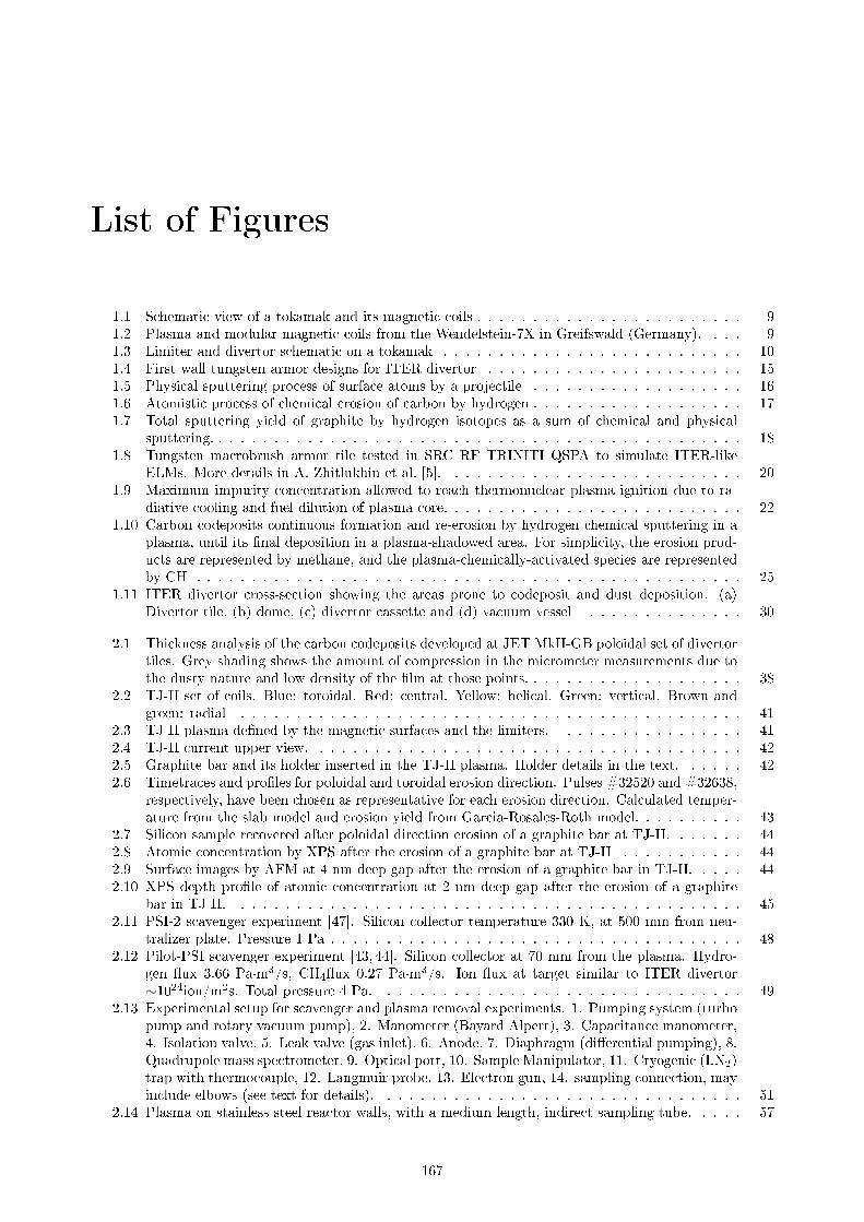
List of Figures
1.1 Schematic view of a tokamak and its magnetic coils . . . . . . . . . . . . . . . . . . . . . . . . 91.2 Plasma and modular magnetic coils from the Wendelstein-7X in Greifswald (Germany). . . . 91.3 Limiter and divertor schematic on a tokamak . . . . . . . . . . . . . . . . . . . . . . . . . . . 101.4 First wall tungsten armor designs for ITER divertor . . . . . . . . . . . . . . . . . . . . . . . 151.5 Physical sputtering process of surface atoms by a projectile . . . . . . . . . . . . . . . . . . . 161.6 Atomistic process of chemical erosion of carbon by hydrogen . . . . . . . . . . . . . . . . . . . 171.7 Total sputtering yield of graphite by hydrogen isotopes as a sum of chemical and physical
sputtering. . . . . . . . . . . . . . . . . . . . . . . . . . . . . . . . . . . . . . . . . . . . . . . . 181.8 Tungsten macrobrush armor tile tested in SRC RF TRINITI QSPA to simulate ITER-like
ELMs. More details in A. Zhitlukhin et al. [5]. . . . . . . . . . . . . . . . . . . . . . . . . . . 201.9 Maximum impurity concentration allowed to reach thermonuclear plasma ignition due to ra-
diative cooling and fuel dilution of plasma core. . . . . . . . . . . . . . . . . . . . . . . . . . . 221.10 Carbon codeposits continuous formation and re-erosion by hydrogen chemical sputtering in a
plasma, until its �nal deposition in a plasma-shadowed area. For simplicity, the erosion prod-ucts are represented by methane, and the plasma-chemically-activated species are representedby CH+. . . . . . . . . . . . . . . . . . . . . . . . . . . . . . . . . . . . . . . . . . . . . . . . . 25
1.11 ITER divertor cross-section showing the areas prone to codeposit and dust deposition. (a)Divertor tile, (b) dome, (c) divertor cassette and (d) vacuum vessel . . . . . . . . . . . . . . 30
2.1 Thickness analysis of the carbon codeposits developed at JET MkII-GB poloidal set of divertortiles. Grey shading shows the amount of compression in the micrometer measurements due tothe dusty nature and low density of the �lm at those points. . . . . . . . . . . . . . . . . . . . 38
2.2 TJ-II set of coils. Blue: toroidal. Red: central. Yellow: helical. Green: vertical. Brown andgreen: radial . . . . . . . . . . . . . . . . . . . . . . . . . . . . . . . . . . . . . . . . . . . . . 41
2.3 TJ-II plasma de�ned by the magnetic surfaces and the limiters. . . . . . . . . . . . . . . . . 412.4 TJ-II current upper view. . . . . . . . . . . . . . . . . . . . . . . . . . . . . . . . . . . . . . . 422.5 Graphite bar and its holder inserted in the TJ-II plasma. Holder details in the text. . . . . . 422.6 Timetraces and pro�les for poloidal and toroidal erosion direction. Pulses #32520 and #32638,
respectively, have been chosen as representative for each erosion direction. Calculated temper-ature from the slab model and erosion yield from Garcia-Rosales-Roth model. . . . . . . . . . 43
2.7 Silicon sample recovered after poloidal direction erosion of a graphite bar at TJ-II. . . . . . . 442.8 Atomic concentration by XPS after the erosion of a graphite bar at TJ-II . . . . . . . . . . . 442.9 Surface images by AFM at 4 nm deep gap after the erosion of a graphite bar in TJ-II. . . . . 442.10 XPS depth pro�le of atomic concentration at 2 nm deep gap after the erosion of a graphite
bar in TJ-II. . . . . . . . . . . . . . . . . . . . . . . . . . . . . . . . . . . . . . . . . . . . . . 452.11 PSI-2 scavenger experiment [47]. Silicon collector temperature 330 K, at 500 mm from neu-
tralizer plate. Pressure 1 Pa . . . . . . . . . . . . . . . . . . . . . . . . . . . . . . . . . . . . . 482.12 Pilot-PSI scavenger experiment [43, 44]. Silicon collector at 70 mm from the plasma. Hydro-
gen �ux 3.66 Pa·m3/s, CH4�ux 0.27 Pa·m3/s. Ion �ux at target similar to ITER divertor∼1024ion/m2s. Total pressure 4 Pa. . . . . . . . . . . . . . . . . . . . . . . . . . . . . . . . . 49
2.13 Experimental setup for scavenger and plasma removal experiments. 1. Pumping system (turbopump and rotary vacuum pump), 2. Manometer (Bayard Alpert), 3. Capacitance manometer,4. Isolation valve, 5. Leak valve (gas inlet), 6. Anode, 7. Diaphragm (di�erential pumping), 8.Quadrupole mass spectrometer, 9. Optical port, 10. Sample Manipulator, 11. Cryogenic (LN2)trap with thermocouple, 12. Langmuir probe, 13. Electron gun, 14. sampling connection, mayinclude elbows (see text for details). . . . . . . . . . . . . . . . . . . . . . . . . . . . . . . . . 51
2.14 Plasma on stainless steel reactor walls, with a medium length, indirect sampling tube. . . . . 57
167

LIST OF FIGURES 168
2.15 Evaporation on stainless steel reactor walls, with a medium, indirect sampling tube. Regionsat 0; 0.14; 0.38; 0.61; 1.1 times. . . . . . . . . . . . . . . . . . . . . . . . . . . . . . . . . . . . 57
2.16 Plasma on carbonized reactor walls (dry), with a medium, indirect sampling tube. . . . . . . 572.17 Evaporation on carbonized reactor walls (dry), with a medium, indirect sampling tube. Regions
at 0; 0.16; 0.47; 0.67; 1.1 times. . . . . . . . . . . . . . . . . . . . . . . . . . . . . . . . . . . . 572.18 Evaporation on stainless steel reactor walls, with a long, direct sampling tube. Regions at 0;
0.12; 0.19; 0.36; 0.46; 0.69; 1.1 times. . . . . . . . . . . . . . . . . . . . . . . . . . . . . . . . . 582.19 Evaporation on stainless steel reactor walls, with a short, direct sampling tube. Regions at 0;
0.24; 0.52; 0.63; 1.1 times. . . . . . . . . . . . . . . . . . . . . . . . . . . . . . . . . . . . . . . 582.20 Evaporation on carbonized reactor walls (dry), with a short, direct sampling tube. Regions at
0; 0.22; 0.45; 0.66; 1.1 times. . . . . . . . . . . . . . . . . . . . . . . . . . . . . . . . . . . . . . 582.21 Evaporation on carbonized reactor walls (humid), with a medium, indirect sampling tube.
Regions (at 0; 0.27; 0.41; 0.90; 1.1 times). . . . . . . . . . . . . . . . . . . . . . . . . . . . . . 582.22 Mass spectra of products during the plasma on stainless steel reactor walls, with a medium
length, indirect sampling tube covered with papy�ex to simulate carbon coating. Point 1 isthe plasma start-up, 2 is the activation of liquid nitrogen trap and 3 is the plasma shutdown. 60
3.1 Scheme for the macrobrush castellation gap simulation, see text for details. . . . . . . . . . . 703.2 Experimental setup for MW plasma. Sample at 40 cm from generator . . . . . . . . . . . . . 713.3 Experimental setup for RF plasma. Sample at 35 cm from generator . . . . . . . . . . . . . . 713.4 a-C:H thickness depth pro�le measured by laser interferometry of samples exposed to DC-
plasma removal in a structure which simulates castellation gaps of 1 mm. A unexposed sampleis used as a reference. The plasma side of the samples is on the right. . . . . . . . . . . . . . 72
3.5 Mass spectrometry of ammonia and main products from erosion of an a-C:H �lm in a He/NH3
DC-plasma. A Si/a-C:H sample was inserted into the plasma and biased +10 V with respectto the plasma. The evolution of this a-C:H �lm thickness is followed by laser interferometry(right axis). Each fringe, i.e. each maximum or minimum, corresponds to around 100 nm of�lm eroded by Equation 3.1. . . . . . . . . . . . . . . . . . . . . . . . . . . . . . . . . . . . . 73
3.6 OES spectra of NH3 MW-plasma at di�erent applied powers in the chamber depicted in Fig-ure 3.2. 75 Pa pressure in main chamber. . . . . . . . . . . . . . . . . . . . . . . . . . . . . . 74
3.7 m/q 27, related to HCN production, during the erosion of a-C:H �lm in NH3 MW-plasma atdi�erent applied powers and sample temperature in the chamber depicted in Figure 3.2. 75Pa pressure in main chamber. . . . . . . . . . . . . . . . . . . . . . . . . . . . . . . . . . . . . 75
3.8 OES spectra of NH3 inductively coupled RF-plasma at di�erent modes in the chamber depictedin Figure 3.3. 50 Pa pressure. Please note that the emission in H-mode is really much largerthan in E-mode, so the measuring time was much shorter to avoid saturation of the detector. 75
3.9 Erosion rates measured by laser interferometry of a-C:H �lms by NH3 inductively coupledRF-plasma at di�erent modes in the chamber depicted in Figure 3.3. 50 Pa pressure. . . . . . 76
3.10 Side view of experimental setup for DC-plasma a-C:D deposition and thermo-oxidation. 1.Gate valve; 2. CaSO4 �lled column for water adsorption of inlet gas. Eventually regeneratedbaking at 120 °C for 2 h; 3. All-metal leak valve; 4. Anode; 5. Electron gun; 6. Stainlesssteel net to limit plasma expansion; 7. Te�on covered cable from the thermocouple; 8. BNcovered cable from the electron gun; 9. Temperature controller by thermocouple; 10. Pumpingsystem (turbo pump and rotary vacuum pump); 11. Capacitance manometer, (a) 1-1000 Torr,(b) 1-1000 mTorr; 12. Optical port; 13. Manometer (Bayard Alpert); 14. Bellow with 1 mmpinhole. The vacuum chamber can be baked by thermocoax in the plasma section and bysilicone rubber covered heater in the rest. . . . . . . . . . . . . . . . . . . . . . . . . . . . . . 79
3.11 PADOS experimental setup at Jülich . . . . . . . . . . . . . . . . . . . . . . . . . . . . . . . . 803.12 Experimental setup at INFIM for thin �lm sequential deposition . . . . . . . . . . . . . . . . 803.13 Side view of experimental setup for samples thermo-oxidation: 1. Turbomolecular pump; 2.
Gate valve; 3. Capacitance manometer (a) 1-1000 Torr, (b) 1-1000 mTorr; 4. Liquid nitrogencold trap; 5. All-metal leak valve; 6. Bellow with 1 mm pinhole; 7. Manometer (BayardAlpert); 8. Ceramic heater; 9. Sample or DIII-D specimen; 10. Thermocouple connection.The vacuum chamber can be baked by silicone rubber covered heater. . . . . . . . . . . . . . 81
3.14 Experimental setup for thermo-oxidation and LIDS analysis at UTIAS . . . . . . . . . . . . . 823.15 D concentration measured by LIDS versus oxidation time for DIII-D codeposits at (a) 286
°C, (b) 350 °C, (c) 385�400 °C. Measurements shown at `-1 h' indicate D concentration in thespecimen before vacuum baking or oxidation. The value shown for `0 h' is after vacuum bakingat experiment temperature but prior to oxidation. . . . . . . . . . . . . . . . . . . . . . . . . 85

LIST OF FIGURES 169
3.16 Comparison of D remaining content due to NO2 and O2 thermo-oxidation at various temper-atures versus gas pressure. . . . . . . . . . . . . . . . . . . . . . . . . . . . . . . . . . . . . . . 85
3.17 Atomic concentration and ratios by XPS from specimens after thermo-oxidation. 10b is anun-treated specimen used as reference. . . . . . . . . . . . . . . . . . . . . . . . . . . . . . . . 85
3.18 Percentages of boron bonding types by XPS from specimens after thermo-oxidation: oxygenand nitride versus boride, borane and carborane. 10b is an un-treated specimen used as reference. 85
3.19 Temperature dependance �tted by Arrhenius equation of D and C removal rates by thermo-oxidation in 2 kPa NO2 on 550 nm, 15% porosity, soft a-C:D �lm. . . . . . . . . . . . . . . . 87
3.20 Pressure dependance �tted by Langmuir isotherm equation of D and C removal rates bythermo-oxidation in NO2 at 350 °C on 550 nm, 15% porosity, soft a-C:D �lm. . . . . . . . . 87
3.21 Mass spectra taken before and during the thermo-oxidation in 20 kPa of NO2 at 275 °C of ahard a-C:D �lm. Inset of lower masses in green. . . . . . . . . . . . . . . . . . . . . . . . . . . 89
3.22 Time evolution of the mass spectra taken during the thermo-oxidation treatment at di�erentconditions of a hard a-C:D �lm deposited on the reactor walls by a DC glow discharge. Points1 and 3 are the injection and evacuation of gas respectively. Jump in signals in point 2 ismade by modifying the �ux to the RGA chamber to enhance sensitivity by means of valve 3bin Figure 3.10. . . . . . . . . . . . . . . . . . . . . . . . . . . . . . . . . . . . . . . . . . . . . 90
3.23 Dust characterization setup for laser ablation of a-C:H codeposits from Ivanova et al. [135] . . 953.24 Experimental setup for dust production studies during laser ablation of tokamak a-C:D code-
posits at IPPLM, Warsaw (Poland). For dust collection experiments two aerogel collectorswere placed at 2 cm from the laser impact point, usually tilted to an angle of 25° with respectto sample. . . . . . . . . . . . . . . . . . . . . . . . . . . . . . . . . . . . . . . . . . . . . . . . 97
3.25 Optical Emission Spectra (OES) during laser ablation of a-C:D laboratory samples in vacuum. 983.26 Optical Emission Spectra (OES) during laser ablation of a TEXTOR limiter tile in di�erent
atmospheres. Series of pulses at the same location. . . . . . . . . . . . . . . . . . . . . . . . . 1013.27 Pictures of surface craters left by laser ablation in various atmospheres. . . . . . . . . . . . . 1023.28 Fast camera images taken at 40 µs after laser impact during laser ablation of a tokamak
carbon codeposit in vacuum and various atmospheres. Di�erent pulses and integration timesare shown. Scale 3.4x3.4 cm. Brightness and contrast are optimized for dust view, not plasmaplume. . . . . . . . . . . . . . . . . . . . . . . . . . . . . . . . . . . . . . . . . . . . . . . . . . 104
3.29 Fast camera images at taken at 40 µs after laser impact during laser ablation of a tokamakcarbon codeposit in di�erent atmospheres at various pressures, and from �rst laser pulse at 50kPa in He and O2. Scale 3.4x3.4 cm. Brightness and contrast are optimized for dust view, notplasma plume. . . . . . . . . . . . . . . . . . . . . . . . . . . . . . . . . . . . . . . . . . . . . 105
3.30 Fast camera images with an aerogel dust collector at 2 cm taken at 40 µs after laser impactduring laser ablation of a tokamak carbon codeposit in vacuum and O2. Brightness andcontrast are optimized for dust view, not plasma plume. . . . . . . . . . . . . . . . . . . . . . 106
3.31 SEM images of the particles recovered in the aerogel after laser ablation in vacuum of a tokamakcarbon codeposit. 10 laser pulses in total . . . . . . . . . . . . . . . . . . . . . . . . . . . . . 107
3.32 Fractional mass of dust particles collected into the aerogel after laser ablation in vacuum of atokamak carbon codeposit with respect to their diameter. 10 laser pulses in total . . . . . . . 108
3.33 Proton spectrum during μ-NRA of a particle captured into the aerogel after laser ablation invacuum of a tokamak carbon codeposit. 10 laser pulses in total. . . . . . . . . . . . . . . . . . 108
3.34 Plasma torch plume for di�erent gases and �uxes in open atmosphere (air). Initial diameterof the plume: 2 mm. . . . . . . . . . . . . . . . . . . . . . . . . . . . . . . . . . . . . . . . . 110
3.35 Erosion of a 2.2 µm-thick, soft a-C:H �lm over silicon by plasma torch at 5 mm height, di�erentgas mixtures and under open atmosphere. Scan velocity 5 mm/s. a) 3000 sccm O2 at 300 W;b) 4000 sccm air at 300 W; c) 5000 sccm N2 at 350 W; d) 5000 sccm Ar + 500 sccm NH3 at300 W; e) 5000 sccm Ar + 200 sccm H2 at 300 W; f) 5000 sccm Ar + 200 sccm O2 at 300 W 111
3.36 Plasma torch treatment in ITER-like castellation gaps. 8200 sccm N2 at 350 W, torch at 2mm height and 5 mm/s velocity. . . . . . . . . . . . . . . . . . . . . . . . . . . . . . . . . . . 111
3.37 Plasma torch setup . . . . . . . . . . . . . . . . . . . . . . . . . . . . . . . . . . . . . . . . . . 1123.38 Graphite erosion setup. 1. plasma torch and holder; 2. copper block; 3. thermocouple; 4.
ohmic oven; 5. graphite sample; 5.a. initial ; 5.b after plasma torch erosion . . . . . . . . . . 1123.39 Graphite removal rate by the plasma torch in open and closed atmosphere at various temper-
atures. 3000 sccm of pure N2, or with 300 sccm O2, at 300 W power. . . . . . . . . . . . . . . 1133.40 N2 plasma torch in closed atmosphere . . . . . . . . . . . . . . . . . . . . . . . . . . . . . . . 1133.41 W/a-C:H �lm treated by plasma torch: 3000 sccm of N2 at 300 W, and 5 mm/s of scan velocity. 114
4.1 Images of WNx �lm deposited by RMS at various %N2 over W �lm in a silicon substrate. . . 126

LIST OF FIGURES 170
4.2 XRD analysis of W2N �lm deposited by RMS (W2N RMS) and pure W �lm deposited byMagnetron Sputtering (W_MS) . . . . . . . . . . . . . . . . . . . . . . . . . . . . . . . . . . . 127
4.3 XPS depth pro�le concentration of a tungsten nitride �lm deposited by RMS at -200 V bias. 1274.4 XPS deconvoluted spectra of W4f and N1s obtained on W2N �lm at 25.5 nm depth. . . . . . 1284.5 TEM cross-section of a W layer nitrided during 1 h. After the nitriding a 30 nm W layer
was deposited in situ on top to protect the bombarded area from atmosphere, and to ease theidenti�cation in TEM. . . . . . . . . . . . . . . . . . . . . . . . . . . . . . . . . . . . . . . . . 128
4.6 TEM cross-section of 10 step SDN multilayer structure composed of 10 nm thick W layersbefore nitriding. After the nitriding a 30 nm W layer was deposited in situ on top to protectthe bombarded area from atmosphere, and to ease the identi�cation in TEM. . . . . . . . . . 128
4.7 XPS deconvoluted spectra of W4f and N1s obtained on plasma nitrided tungsten sample afterremoving the initial 5 nm of pure W . . . . . . . . . . . . . . . . . . . . . . . . . . . . . . . . 129
4.8 High resolution AES depth pro�le of 10 step SDN multilayer structure composed of 10 nmthick W layers before nitriding. . . . . . . . . . . . . . . . . . . . . . . . . . . . . . . . . . . . 129
4.9 SIMS depth pro�le of 10 step SDN multilayer structure composed of 10 nm thick W layersbefore nitriding. . . . . . . . . . . . . . . . . . . . . . . . . . . . . . . . . . . . . . . . . . . . . 129
4.10 TEM cross-section of 10 step SDN multilayer structure composed of 3 nm thick W layers beforenitriding. . . . . . . . . . . . . . . . . . . . . . . . . . . . . . . . . . . . . . . . . . . . . . . . 130
4.11 XPS depth pro�le of 10 step SDN multilayer structure composed of 3 nm thick W layers beforenitriding. . . . . . . . . . . . . . . . . . . . . . . . . . . . . . . . . . . . . . . . . . . . . . . . 131
4.12 XRD analysis comparison of 10 step SDN multilayer structure composed of 3 nm thick Wlayers before nitriding and a blank sample from non-nitrided layers. . . . . . . . . . . . . . . 131
4.13 High resolution AES depth pro�le of 10 step SDN multilayer structure composed of 2 nm thickW2N layers by RMS before nitriding. . . . . . . . . . . . . . . . . . . . . . . . . . . . . . . . . 131
4.14 TEM cross-section of 10 step SDN multilayer structure composed of 2 nm thick W2N layersby RMS before nitriding. . . . . . . . . . . . . . . . . . . . . . . . . . . . . . . . . . . . . . . 131
4.15 Comparison of tungsten sputtering yields obtained experimentally and calculated by TRIMfrom K. Schmid et al [26]. . . . . . . . . . . . . . . . . . . . . . . . . . . . . . . . . . . . . . . 134
4.16 Surface blistering of tungsten surfaces under large deuterium ion �ux in di�erent conditions. . 1374.17 Nano-PSI expanding thermal plasma device. . . . . . . . . . . . . . . . . . . . . . . . . . . . . 1384.18 Pilot-PSI linear plasma accelerator. . . . . . . . . . . . . . . . . . . . . . . . . . . . . . . . . . 1394.19 W2N layer bombarded with D2 RF-plasma during 1 h at -200 V. After the bombardment a 50
nm W layer was deposited in situ on top to protect the bombarded area from atmosphere. . . 1404.20 Tungsten square samples exposed to plasmas in Nano-PSI device at di�erent bias and exposure
times . . . . . . . . . . . . . . . . . . . . . . . . . . . . . . . . . . . . . . . . . . . . . . . . . . 1404.21 SEM image and pictures of W2N �lms subjected to D2 plasmas at -40 V bias in Pilot-PSI at
di�erent �uences. . . . . . . . . . . . . . . . . . . . . . . . . . . . . . . . . . . . . . . . . . . 1414.22 SEM image and pictures of W sheets nitrided in a N2 plasma in Pilot-PSI at -70 V bias until
a �uence of 5·1024 N/m2, and after subjected to D2 plasmas at -40 V bias at di�erent �uences. 142
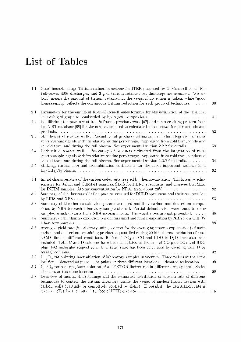
List of Tables
1.1 Good housekeeping: Tritium reduction scheme for ITER proposed by G. Counsell et al [10].Full-power 400s discharges, and 3 g of tritium retained per discharge are assumed. �No ac-tion� means the amount of tritium retained in the vessel if no action is taken, while �goodhousekeeping� re�ects the continuous tritium reduction for each group of techniques. . . . . 30
2.1 Parameters for the empirical Roth�García-Rosales formula for the estimation of the chemicalsputtering of graphite bombarded by hydrogen isotopes ions. . . . . . . . . . . . . . . . . . . 41
2.2 Equilibrium temperature at 0.1 Pa from a previous work [67] and mass cracking pattern fromthe NIST database [68] for the m/q values used to calculate the concentration of reactants andproducts. . . . . . . . . . . . . . . . . . . . . . . . . . . . . . . . . . . . . . . . . . . . . . . . 52
2.3 Stainless steel reactor walls. Percentage of products estimated from the integration of massspectroscopic signals with its relative residue percentage: evaporated from cold trap, condensedat cold trap, and during the full plasma. See experimental section 2.2.2 for details. . . . . . . 53
2.4 Carbonized reactor walls. Percentage of products estimated from the integration of massspectroscopic signals with its relative residue percentage: evaporated from cold trap, condensedat cold trap, and during the full plasma. See experimental section 2.2.2 for details. . . . . . . 54
2.5 Sticking, surface loss and recombination coe�cients for the most important radicals in aH2/CH4/N2 plasma . . . . . . . . . . . . . . . . . . . . . . . . . . . . . . . . . . . . . . . . . 62
3.1 Initial characteristics of the carbon codeposits treated by thermo-oxidation. Thickness by ellip-sometry for Jülich and CIEMAT samples, SIMS for DIII-D specimens, and cross-section SEMfor INFIM samples. Atomic concentration by NRA, error about 20%. . . . . . . . . . . . . . 82
3.2 Summary of the thermo-oxidation parameters used for DIII-D specimens and their compositionby LIDS and XPS . . . . . . . . . . . . . . . . . . . . . . . . . . . . . . . . . . . . . . . . . . . 83
3.3 Summary of the thermo-oxidation parameters used and �nal carbon and deuterium compo-sition by NRA for each laboratory sample studied. Partial delamination were found in somesamples, which distorts their NRA measurements. The worst cases are not presented. . . . . 86
3.4 Summary of the thermo-oxidation parameters used and �nal composition by NRA for a-C:H/Wlaboratory samples. . . . . . . . . . . . . . . . . . . . . . . . . . . . . . . . . . . . . . . . . . . 88
3.5 Averaged yield rate (in arbitrary units, see text for the averaging process explanation) of maincarbon and deuterium containing products, quanti�ed during 20 kPa thermo-oxidation of harda-C:D �lms at di�erent conditions. Ratios of CO2 to CO and HDO to D2O have also beenincluded. Total C and D columns have been calculated as the sum of CO plus CO2 and HDOplus D2O molecules respectively. D/C (gas) ratio has been calculated by dividing total D bytotal C columns. . . . . . . . . . . . . . . . . . . . . . . . . . . . . . . . . . . . . . . . . . . . 92
3.6 C+/Dα ratio during laser ablation of laboratory samples in vacuum. Three pulses at the samelocation �denoted as pulse�, or pulses at three di�erent locations �denoted as location�. . 99
3.7 C+/Dα ratio during laser ablation of a TEXTOR limiter tile in di�erent atmospheres. Seriesof pulses at the same location . . . . . . . . . . . . . . . . . . . . . . . . . . . . . . . . . . . . 99
3.8 Overview of merits, shortcomings and the estimated detritiation or erosion rate of di�erenttechniques to control the tritium inventory inside the vessel of nuclear fusion devices withcarbon walls (partially or completely covered by them). If possible, the detritiation rate isgiven in gT/s for the 150 m2 surface of ITER divertor. . . . . . . . . . . . . . . . . . . . . . . 116
171

LIST OF TABLES 172
3.9 Possible integrated scenario for tritium control in a future nuclear fusion device with di�erentwalls combination (considering their associated retention and interactions) and carbon-relatedmaterials. Based on �good housekeeping� by Counsell et al. [10]. A mean tritium retention of1 g per pulse is considered, taking ITER pulses as a guide (full power, 400 s, 10 pulses/dayand 5 days/week). """: Essential; "": Highly recommended; ": E�ective; ≈ limited oruncertain e�ectiveness. . . . . . . . . . . . . . . . . . . . . . . . . . . . . . . . . . . . . . . . . 122

Bibliography
[1] W. Bank, Economics of Adaptation to Climate Change : Synthesis Report (World Bank, WashingtonD.C., 2010).
[2] I. E. Agency, World Energy Outlook 2013. (International Energy Agency, Paris, France, 2013).
[3] F. F. Chen, An indispensable truth: how fusion power can save the planet (Springer, New York, 2011).
[4] A. Scarabosio, et al., Journal of Nuclear Materials 463, 49 (2015).
[5] A. Zhitlukhin, et al., Journal of Nuclear Materials 363�365, 301 (2007).
[6] A. Kirschner, et al., Journal of Nuclear Materials 390-391, 152 (2009).
[7] K. Schmid, M. Baldwin, R. Doerner, Journal of Nuclear Materials 337�339, 862 (2005).
[8] F. L. Tabares, et al., Plasma Physics and Controlled Fusion 44, L37 (2002).
[9] F. L. Tabarés, Plasma Sources Sci. Technol. 22, 033001 (2013).
[10] G. Counsell, et al., Plasma Physics and Controlled Fusion 48, B189 (2006).
[11] J. A. Ferreira, F. L. Tabarés, Journal of Physics: Conference Series 100, 062026 (2008).
[12] A. A. Haasz, S. Chiu, J. E. Pierre, Y. I. Gudimenko, J. Vac. Sci. Technol. A 14, 184 (1996).
[13] J. Roth, et al., Plasma Physics and Controlled Fusion 50, 103001 (2008).
[14] M. Rubel, et al., 24th IAEA Fusion Energy Conference (IAEA, San Diego (USA), 2012), vol. EX, pp.P5�10.
[15] A. Haasz, et al., Journal of Nuclear Materials 390-391, 626 (2009).
[16] I. Tanarro, J. Ferreira, V. Herrero, F. Tabarés, C. Gómez-Aleixandre, Journal of Nuclear Materials390-391, 696 (2009).
[17] S. Alberici, H. K. Hinssen, R. Moormann, C. H. Wu, Journal of Nuclear Materials 266�269, 754(1999).
[18] S. Alberici, et al., Journal of Nuclear Materials 258�263, Part 1, 764 (1998).
[19] R. A. Causey, W. L. Chrisman, W. L. Hsu, R. Anderl, B. Wishard, Journal of Vacuum Science &Technology A 7, 1078 (1989).
[20] A. A. Haasz, C. K. Tsui, J. W. Davis, R. Ochoukov, Phys. Scr. T128, 55 (2007).
[21] C. Tsui, et al., Journal of Nuclear Materials 395, 1 (2009).
[22] M. Shimada, R. A. Pitts, Journal of Nuclear Materials 415, S1013 (2011).
[23] C. Stancu, M. Teodorescu, A. Galca, G. Dinescu, Surface and Coatings Technology 205, Supplement2, S435 (2011).
[24] G. Dinescu, E. Ionita, I. Luciu, C. Grisolia, Fusion Engineering and Design 82, 2311 (2007).
[25] S. Rosanvallon, et al., Journal of Nuclear Materials 390�391, 57 (2009).
[26] K. Schmid, et al., Nucl. Fusion 50, 025006 (2010).
173

BIBLIOGRAPHY 174
[27] S. Brezinsek, Journal of Nuclear Materials 463, 11 (2015).
[28] R. Neu, et al., Journal of Nuclear Materials 438, Supplement, S34 (2013).
[29] R. Pitts, et al., Journal of Nuclear Materials 438, Supplement, S48 (2013).
[30] A. von Keudell, Thin Solid Films 402, 1 (2002).
[31] W. Jacob, J. Roth, Sputtering by Particle Bombardment (Springer Berlin Heidelberg, Berlin, Heidel-berg), vol. 110, pp. 329�400.
[32] W. Jacob, Thin Solid Films 326, 1 (1998).
[33] D. J. Dagel, C. M. Mallouris, J. R. Doyle, J. Appl. Phys. 79, 8735 (1996).
[34] M. Bauer, T. Schwarz-Selinger, W. Jacob, A. von Keudell, J. Appl. Phys. 98, 073302 (2005).
[35] A. W. Kleyn, N. J. L. Cardozo, U. Samm, Phys. Chem. Chem. Phys. 8, 1761 (2006).
[36] J. Roth, et al., Journal of Nuclear Materials 390-391, 1 (2009).
[37] T. Loarer, Journal of Nuclear Materials 390-391, 20 (2009).
[38] M. Mayer, V. Rohde, A. von Keudell, A. U. Team, Journal of Nuclear Materials 313-316, 429 (2003).
[39] G. Federici, et al., Journal of Nuclear Materials 313-316, 11 (2003).
[40] G. Federici, et al., Nuclear Fusion 41, 1967 (2001).
[41] F. Tabares, et al., Journal of Nuclear Materials 337-339, 867 (2005).
[42] F. L. Tabarés, V. Rohde, t. A. U. Team, Plasma Physics and Controlled Fusion 46, B381 (2004).
[43] F. Tabarés, et al., Journal of Nuclear Materials 415, S793 (2011).
[44] F. L. Tabarés, et al., Phys. Rev. Lett. 105, 175006 (2010).
[45] J. A. Ferreira, F. L. Tabarés, Plasma Sources Sci. Technol. 18, 034019 (2009).
[46] F. Tabarés, D. Tafalla, J. Ferreira, Chemical Vapor Deposition 13, 335 (2007).
[47] W. Bohmeyer, et al., Journal of Nuclear Materials 390-391, 560 (2009).
[48] E. Vassallo, et al., Plasma Physics and Controlled Fusion 52, 075014 (2010).
[49] E. Vassallo, A. Cremona, L. Laguardia, G. Grosso, Plasma Phys. Control. Fusion 53, 032002 (2011).
[50] J. Coad, et al., Nuclear Fusion 46, 350 (2006).
[51] J. Roth, Phys. Scr. 2006, 37 (2006).
[52] D. G. Whyte, G. R. Tynan, R. P. Doerner, J. N. Brooks, Nucl. Fusion 41, 47 (2001).
[53] P. Kornejew, W. Bohmeyer, H.-D. Reiner, C. H. Wu, Phys. Scr. 2001, 29 (2001).
[54] B. Pégourié, et al., Journal of Nuclear Materials 438, Supplement, S120 (2013).
[55] B. Unterberg, FST 61, 199 (2012).
[56] T. C. Hender, J. L. Cantrell, J. H. Harris, Studies of a �exible heliac con�guration, Tech. Rep.ORNL/TM-10374 OSTI ID: 6007697 , Junta de Energia Nuclear, Madrid (Spain). Div. de Fusion(1987).
[57] T. C. Hender, et al., Report ORNL/TM-10374 (1987) OSTI ID: 6007697 (1988).
[58] F. Tabarés, D. Tafalla, T. Wurgie, J. Ferreira, Journal of Nuclear Materials 390-391, 76 (2009).
[59] A. Grill, Cold plasma in materials fabrication: from fundamentals to applications (IEEE Press ; Insti-tute of Electrical and Electronics Engineers, Piscataway, NJ; New York, 1994).

BIBLIOGRAPHY 175
[60] M. A. Lieberman, A. J. Lichtenberg, Principles of plasma discharges and materials processing (Wiley,New jersey, 2005), second edn.
[61] O. Auciello, Plasma Diagnostics: Discharge parameters and chemistry (Academic Press, Boston [u.a.],1989).
[62] M. Mozetic, A. Vesel, D. Alegre, F. L. Tabares, Journal of Applied Physics 110, 053302 (2011).
[63] D. Alegre, J. A. Ferreira, F. L. Tabarés, J. Mass Spectrom. 49, 342 (2014).
[64] E. Vassallo, et al., Vacuum 86, 1528 (2012).
[65] T. Schwarz-Selinger, C. Hopf, C. Sun, W. Jacob, Journal of Nuclear Materials 363-365, 174 (2007).
[66] N. Mutsukura, Plasma Chemistry and Plasma Processing 21, 265 (2001).
[67] J. A. Ferreira, F. L. Tabares, J. Vac. Sci. Technol. A 25, 246 (2007).
[68] P. Linstrom, W. Mallard, NIST Chemistry WebBook, NIST Standard Reference Database Number 69.http://webbook.nist.gov (National Institute of Standards and Technology, Gaithersburg MD, 20899).
[69] I. Tanarro, et al., J. Phys. Chem. A 111, 9003 (2007).
[70] E. Carrasco, M. Jiménez-Redondo, I. Tanarro, V. J. Herrero, Phys. Chem. Chem. Phys. 13, 19561(2011).
[71] D. Liu, E. R. Fisher, Journal of Vacuum Science & Technology A: Vacuum, Surfaces, and Films 25,368 (2007).
[72] I. Tanarro, T. de los Arcos, C. Domingo, V. Herrero, M. Sanz, Vacuum 64, 457 (2002).
[73] A. Gorodetsky, et al., Journal of Nuclear Materials 337-339, 892 (2005).
[74] H. Kojima, H. Toyoda, H. Sugai, Applied Physics Letters 55, 1292 (1989).
[75] D. Liu, I. T. Martin, J. Zhou, E. R. Fisher, Pure and Applied Chemistry 78, 1187 (2006).
[76] C. Hopf, T. Schwarz-Selinger, W. Jacob, A. von Keudell, J. Appl. Phys. 87, 2719 (2000).
[77] J. Perrin, Journal of Vacuum Science & Technology A: Vacuum, Surfaces, and Films 16, 278 (1998).
[78] H. Singh, J. W. Coburn, D. B. Graves, J. Appl. Phys. 88, 3748 (2000).
[79] S. F. Adams, T. A. Miller, Plasma Sources Science and Technology 9, 248 (2000).
[80] M. J. Kushner, Journal of Applied Physics 71, 4173 (1992).
[81] A. Okita, et al., Journal of Applied Physics 99, 014302 (2006).
[82] M. Mao, A. Bogaerts, Journal of Physics D: Applied Physics 43, 205201 (2010).
[83] I. Mendez, F. Gordillo-Vazquez, V. Herrero, I. Tanarro, J. Phys. Chem. A 110, 6060 (2006).
[84] S. Kodama, Bull. Chem. Soc. Jpn. 56, 2355 (1983).
[85] S. Kodama, Bull. Chem. Soc. Jpn. 56, 2363 (1983).
[86] F. Hempel, P. B. Davies, D. Lo�hagen, L. Mechold, J. Röpcke, Plasma Sources Science and Technology12, S98 (2003).
[87] C. Haggart, C. Winkler, Can. J. Chem. 38, 329 (1960).
[88] H. Evans, G. R. FreemaN, C. Winkler, Can. J. Chem 34, 1271 (1956).
[89] J. Ferreira, F. Tabarés, D. Tafalla, Journal of Nuclear Materials 363-365, 888 (2007).
[90] K. Hiraoka, K. Aoyama, K. Morise, Can. J. Chem. 63, 2899 (1985).
[91] J. Ferreira, F. Tabarés, D. Tafalla, Journal of Nuclear Materials 390-391, 593 (2009).
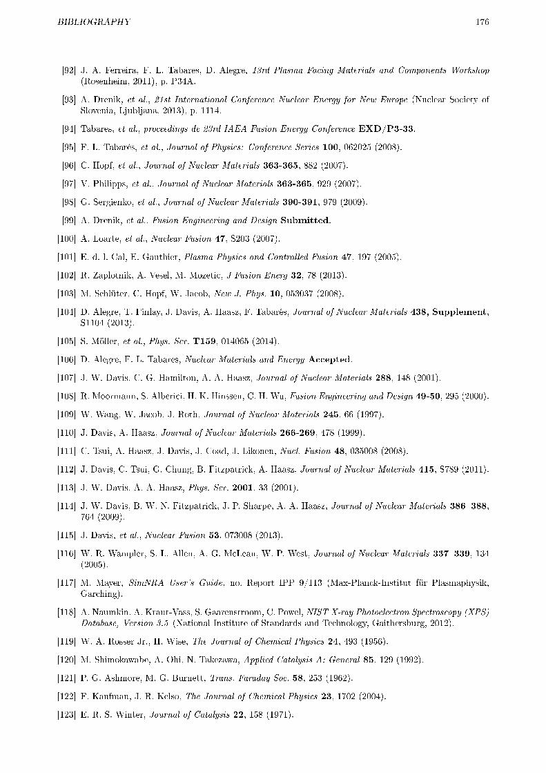
BIBLIOGRAPHY 176
[92] J. A. Ferreira, F. L. Tabares, D. Alegre, 13rd Plasma Facing Materials and Components Workshop(Rosenheim, 2011), p. P34A.
[93] A. Drenik, et al., 21st International Conference Nuclear Energy for New Europe (Nuclear Society ofSlovenia, Ljubljana, 2013), p. 1114.
[94] Tabares, et al., proceedings de 23rd IAEA Fusion Energy Conference EXD/P3-33.
[95] F. L. Tabarés, et al., Journal of Physics: Conference Series 100, 062025 (2008).
[96] C. Hopf, et al., Journal of Nuclear Materials 363-365, 882 (2007).
[97] V. Philipps, et al., Journal of Nuclear Materials 363-365, 929 (2007).
[98] G. Sergienko, et al., Journal of Nuclear Materials 390-391, 979 (2009).
[99] A. Drenik, et al., Fusion Engineering and Design Submitted.
[100] A. Loarte, et al., Nuclear Fusion 47, S203 (2007).
[101] E. d. l. Cal, E. Gauthier, Plasma Physics and Controlled Fusion 47, 197 (2005).
[102] R. Zaplotnik, A. Vesel, M. Mozetic, J Fusion Energ 32, 78 (2013).
[103] M. Schlüter, C. Hopf, W. Jacob, New J. Phys. 10, 053037 (2008).
[104] D. Alegre, T. Finlay, J. Davis, A. Haasz, F. Tabarés, Journal of Nuclear Materials 438, Supplement,S1104 (2013).
[105] S. Möller, et al., Phys. Scr. T159, 014065 (2014).
[106] D. Alegre, F. L. Tabares, Nuclear Materials and Energy Accepted.
[107] J. W. Davis, C. G. Hamilton, A. A. Haasz, Journal of Nuclear Materials 288, 148 (2001).
[108] R. Moormann, S. Alberici, H. K. Hinssen, C. H. Wu, Fusion Engineering and Design 49-50, 295 (2000).
[109] W. Wang, W. Jacob, J. Roth, Journal of Nuclear Materials 245, 66 (1997).
[110] J. Davis, A. Haasz, Journal of Nuclear Materials 266-269, 478 (1999).
[111] C. Tsui, A. Haasz, J. Davis, J. Coad, J. Likonen, Nucl. Fusion 48, 035008 (2008).
[112] J. Davis, C. Tsui, G. Chung, B. Fitzpatrick, A. Haasz, Journal of Nuclear Materials 415, S789 (2011).
[113] J. W. Davis, A. A. Haasz, Phys. Scr. 2001, 33 (2001).
[114] J. W. Davis, B. W. N. Fitzpatrick, J. P. Sharpe, A. A. Haasz, Journal of Nuclear Materials 386�388,764 (2009).
[115] J. Davis, et al., Nuclear Fusion 53, 073008 (2013).
[116] W. R. Wampler, S. L. Allen, A. G. McLean, W. P. West, Journal of Nuclear Materials 337�339, 134(2005).
[117] M. Mayer, SimNRA User's Guide, no. Report IPP 9/113 (Max-Planck-Institut für Plasmaphysik,Garching).
[118] A. Naumkin, A. Kraut-Vass, S. Gaarenstroom, C. Powel, NIST X-ray Photoelectron Spectroscopy (XPS)Database, Version 3.5 (National Institute of Standards and Technology, Gaithersburg, 2012).
[119] W. A. Rosser Jr., H. Wise, The Journal of Chemical Physics 24, 493 (1956).
[120] M. Shimokawabe, A. Ohi, N. Takezawa, Applied Catalysis A: General 85, 129 (1992).
[121] P. G. Ashmore, M. G. Burnett, Trans. Faraday Soc. 58, 253 (1962).
[122] F. Kaufman, J. R. Kelso, The Journal of Chemical Physics 23, 1702 (2004).
[123] E. R. S. Winter, Journal of Catalysis 22, 158 (1971).
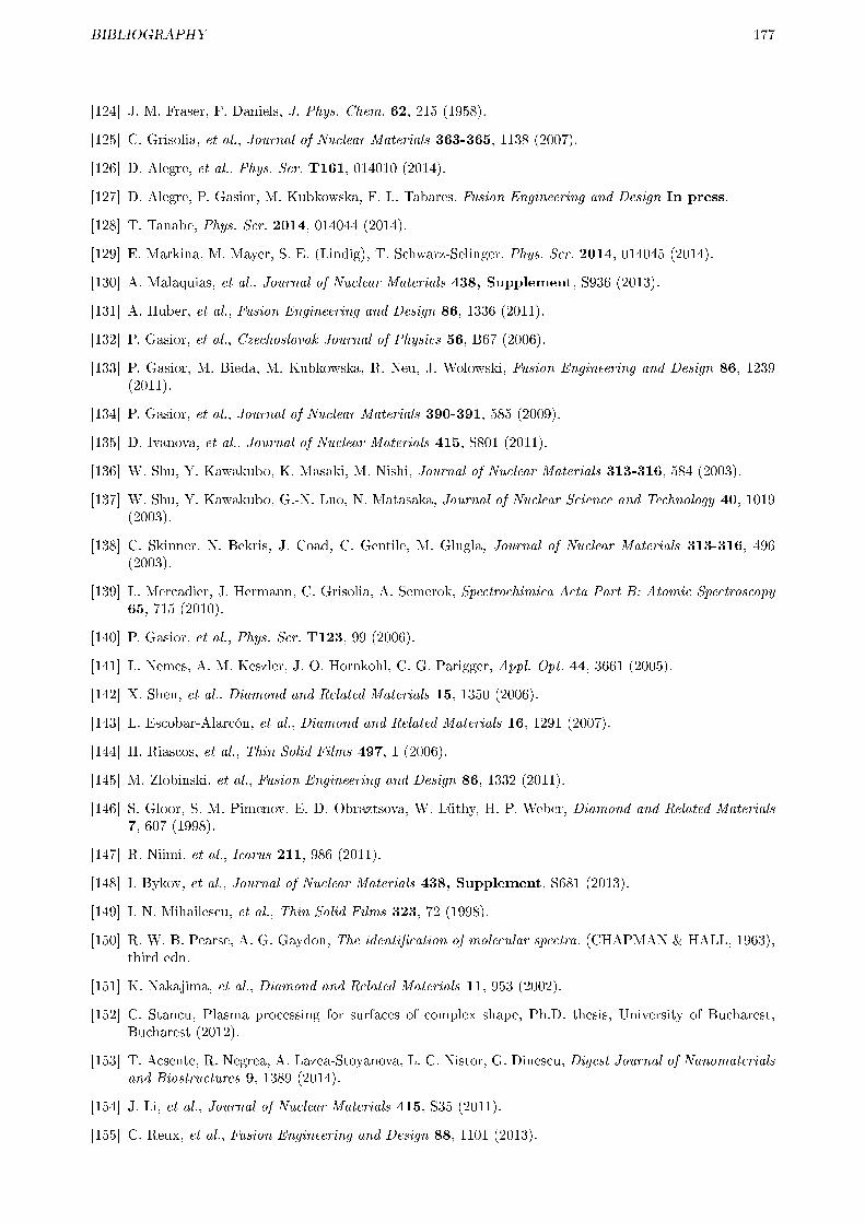
BIBLIOGRAPHY 177
[124] J. M. Fraser, F. Daniels, J. Phys. Chem. 62, 215 (1958).
[125] C. Grisolia, et al., Journal of Nuclear Materials 363-365, 1138 (2007).
[126] D. Alegre, et al., Phys. Scr. T161, 014010 (2014).
[127] D. Alegre, P. Gasior, M. Kubkowska, F. L. Tabares, Fusion Engineering and Design In press.
[128] T. Tanabe, Phys. Scr. 2014, 014044 (2014).
[129] E. Markina, M. Mayer, S. E. (Lindig), T. Schwarz-Selinger, Phys. Scr. 2014, 014045 (2014).
[130] A. Malaquias, et al., Journal of Nuclear Materials 438, Supplement, S936 (2013).
[131] A. Huber, et al., Fusion Engineering and Design 86, 1336 (2011).
[132] P. Gasior, et al., Czechoslovak Journal of Physics 56, B67 (2006).
[133] P. Gasior, M. Bieda, M. Kubkowska, R. Neu, J. Wolowski, Fusion Engineering and Design 86, 1239(2011).
[134] P. Gasior, et al., Journal of Nuclear Materials 390-391, 585 (2009).
[135] D. Ivanova, et al., Journal of Nuclear Materials 415, S801 (2011).
[136] W. Shu, Y. Kawakubo, K. Masaki, M. Nishi, Journal of Nuclear Materials 313-316, 584 (2003).
[137] W. Shu, Y. Kawakubo, G.-N. Luo, N. Matasaka, Journal of Nuclear Science and Technology 40, 1019(2003).
[138] C. Skinner, N. Bekris, J. Coad, C. Gentile, M. Glugla, Journal of Nuclear Materials 313-316, 496(2003).
[139] L. Mercadier, J. Hermann, C. Grisolia, A. Semerok, Spectrochimica Acta Part B: Atomic Spectroscopy65, 715 (2010).
[140] P. Gasior, et al., Phys. Scr. T123, 99 (2006).
[141] L. Nemes, A. M. Keszler, J. O. Hornkohl, C. G. Parigger, Appl. Opt. 44, 3661 (2005).
[142] X. Shen, et al., Diamond and Related Materials 15, 1350 (2006).
[143] L. Escobar-Alarcón, et al., Diamond and Related Materials 16, 1291 (2007).
[144] H. Riascos, et al., Thin Solid Films 497, 1 (2006).
[145] M. Zlobinski, et al., Fusion Engineering and Design 86, 1332 (2011).
[146] S. Gloor, S. M. Pimenov, E. D. Obraztsova, W. Lüthy, H. P. Weber, Diamond and Related Materials7, 607 (1998).
[147] R. Niimi, et al., Icarus 211, 986 (2011).
[148] I. Bykov, et al., Journal of Nuclear Materials 438, Supplement, S681 (2013).
[149] I. N. Mihailescu, et al., Thin Solid Films 323, 72 (1998).
[150] R. W. B. Pearse, A. G. Gaydon, The identi�cation of molecular spectra. (CHAPMAN & HALL, 1963),third edn.
[151] K. Nakajima, et al., Diamond and Related Materials 11, 953 (2002).
[152] C. Stancu, Plasma processing for surfaces of complex shape, Ph.D. thesis, University of Bucharest,Bucharest (2012).
[153] T. Acsente, R. Negrea, A. Lazea-Stoyanova, L. C. Nistor, G. Dinescu, Digest Journal of Nanomaterialsand Biostructures 9, 1389 (2014).
[154] J. Li, et al., Journal of Nuclear Materials 415, S35 (2011).
[155] C. Reux, et al., Fusion Engineering and Design 88, 1101 (2013).

BIBLIOGRAPHY 178
[156] T. Schwarz-Selinger, U. v. Toussaint, C. Hopf, W. Jacob, Phys. Scr. T138, 014009 (2009).
[157] S. Möller, Fundamental processes of plasma and reactive gas surface treatment for the recovery ofhydrogen isotopes from carbon co-deposits in fusion devices, Ph.D. thesis, Heinrich-Heine-Universität,Düsseldorf (2013).
[158] T. Wauters, et al., Nuclear Fusion 53, 123001 (2013).
[159] D. Alegre, et al., europhysics conference abstracts (Berlin, Germany, 2014), vol. 38F, p. P1.027.
[160] D. Neuwirth, V. Rohde, T. Schwarz-Selinger, ASDEX Upgrade Team, Plasma Physics and ControlledFusion 54, 085008 (2012).
[161] M. Oberko�er, et al., Journal of Nuclear Materials 438, Supplement, S258 (2013).
[162] C. C. Baker, S. I. Shah, Journal of Vacuum Science & Technology A: Vacuum, Surfaces, and Films 20,1699 (2002).
[163] T. Migita, R. Kamei, T. Tanaka, K. Kawabata, Applied Surface Science 169-170, 362 (2001).
[164] Y. G. Shen, et al., Journal of Applied Physics 88, 1380 (2000).
[165] F. C. So, E. Kolawa, X.-A. Zhao, M.-A. Nicolet, Thin Solid Films 153, 507 (1987).
[166] Z. Wang, Z. Liu, Z. Yang, S. Shingubara, Microelectronic Engineering 85, 395 (2008).
[167] M. L. Addonizio, A. Castaldo, A. Antonaia, E. Gambale, L. Iemmo, Journal of Vacuum Science &Technology A: Vacuum, Surfaces, and Films 30, 031506 (2012).
[168] D. Alegre, et al., Romanian Reports in Physics, 67, 532 (2015).
[169] G. Meisl, New Journal of Physics 16, 093018 (2014).
[170] H. L. Zhang, D. Z. Wang, N. K. Huang, Applied Surface Science 150, 34 (1999).
[171] O. V. Ogorodnikova, et al., Phys. Scr. 2011, 014034 (2011).
[172] G. Meisl, Journal of Nuclear Materials 463, 668 (2015).
[173] Y. Shen, Y. Mai, W. McBride, Q. Zhang, D. McKenzie, Thin Solid Films 372, 257 (2000).
[174] G. Samsonow, Nitridi (Naukova Dumka, Kiev, 1969).
[175] H. T. Lee, M. Ishida, Y. Ohtsuka, Y. Ueda, Phys. Scr. 2014, 014021 (2014).
[176] M. Hugon, et al., Applied Surface Science 38, 269 (1989).
[177] A. Zalar, Thin Solid Films 124, 223 (1985).
[178] A. Rusinov, et al., Plasma and Fusion Research 7, 1405105 (2012).
[179] Y. YAMAMURA, H. TAWARA, Atomic Data and Nuclear Data Tables 62, 149 (1996).
[180] A. Rusinov, et al., Eng. Sci. Rep., Kyushu Univ. 34, 1 (2012).
[181] T. Kawasaki, Y. Manabe, K. Katayama, T. Takeishi, M. Nishikawa, FST 48, 581 (2005).
[182] W. M. Shu, et al., Journal of Nuclear Materials 390�391, 1017 (2009).
[183] M. Y. Ye, H. Kanehara, S. Fukuta, N. Ohno, S. Takamura, Journal of Nuclear Materials 313�316, 72(2003).
[184] W. Wang, J. Roth, S. Lindig, C. H. Wu, Journal of Nuclear Materials 299, 124 (2001).
[185] L. Gao, W. Jacob, P. Wang, U. v. Toussaint, A. Manhard, Phys. Scr. 2014, 014023 (2014).
[186] W. Eckstein, Max-Planck Inst. Plasma Phys. Rep. IPP9/132 (2002).
[187] H. Y. Xu, et al., 14th Plasma Facing materials and Components conference (Juelich (Germany), 2013),vol. Poster, p. A151.
[188] A. de Castro, D. Alegre, F. L. Tabarés, Journal of Nuclear Materials 463, 676 (2015).