Test, redesign and construction of a new water cooling ...
17
Proceedings of the MEDSI 2014 Conference Melbourne, Australia - October 2014 1 Test, redesign and construction of a new water cooling pump slab bench Carles Colldelram, Marcos Quispe, David Carles, Joan Casas, Juan José Manotas, Llibert Ribó, Gabriel Peña CELLS-ALBA Carretera BP 1413, de Cerdanyola del Vallès a Sant Cugat del Vallès, Km. 3,3, 08290 Cerdanyola del Vallès (Barcelona), Spain [email protected]; [email protected]; [email protected]; [email protected]; [email protected]; [email protected]; [email protected] Abstract -The water cooling system at ALBA is divided in two main sub-systems. First the consumption side which consists of four independent circuits, each one with an independent dedicated pumping unit: Storage Ring, Booster, Experimental Area and Service Area. The second one is the production side where all four circuits are collected into a common return circuit where there are mainly the heat exchangers and a buffer tank, ending at the four circuits aspiration manifold. Consequently the return circuit to the production side is a huge piping which needs a pump powered by an asynchronous motor of about 75kW. During the facility start up the maintenance team realized about too much recurrent unexpected reparations of this common return pumping unit. ALBA pump bench standard design consists of a twin pump unit mounted on a single bench. A simulation with FEA analysis tools and field measurements on the bench, by means of accelerometers, has shine out the overlap of the two main motor harmonic excitations on the two first resonance modes of the mechanical bench at about 50 Hz and 75 Hz, reaching up to 4 mm amplitude. A new design of the bench has been proposed, aimed to push the resonance modes to higher frequencies far away of the powerful harmonic excitations increasing in turn, the rigidity and therefore reducing the deformation amplitudes. Taking advantage of the need for this new design, also the mechanical interfaces have been improved. A new slab bench prototype has been constructed and tested, reaching up resonances close to 200 Hz and it is ready for installation during next shut down. By means of this new development, pumping benches design criteria is clarified for the rest of pumps. The new design will be applied to all services: water cooling as well as air conditioning which are still based on the initial ALBA standard approach. Keywords: Cooling, slab, cooling pump bench, vibrations, cooling motor-pump unit. 1. Introduction The ALBA deionized water cooling system is based on a main common return which collects the four cooling rings, storage ring, booster, service area and experimental area. Consequently the common return circuit needs a huge pumping unit, P11, which deals with all flow of the whole cooling system. Figure 1 shows a basic sketch of this cooling system. This pumping unit is supported by means a vibration isolation slab bench which includes two identical pumping units, the working one and the redundancy for system reliability, Figure 2 shows the current slab design.
Transcript of Test, redesign and construction of a new water cooling ...
Proceedings of the MEDSI 2014 Conference
Melbourne, Australia - October 2014
1
Test, redesign and construction of a new water cooling pump slab bench
Carles Colldelram, Marcos Quispe, David Carles, Joan Casas, Juan José Manotas, Llibert Ribó, Gabriel Peña
CELLS-ALBA Carretera BP 1413, de Cerdanyola del Vallès a Sant Cugat del Vallès, Km. 3,3, 08290 Cerdanyola del
Vallès (Barcelona), Spain [email protected]; [email protected]; [email protected]; [email protected]; [email protected];
[email protected]; [email protected]
Abstract -The water cooling system at ALBA is divided in two main sub-systems. First the consumption side which consists of four independent circuits, each one with an independent dedicated pumping unit: Storage Ring, Booster, Experimental Area and Service Area. The second one is the production side where all four circuits are collected into a common return circuit where there are mainly the heat exchangers and a buffer tank, ending at the four circuits aspiration manifold. Consequently the return circuit to the production side is a huge piping which needs a pump powered by an asynchronous motor of about 75kW. During the facility start up the maintenance team realized about too much recurrent unexpected reparations of this common return pumping unit. ALBA pump bench standard design consists of a twin pump unit mounted on a single bench. A simulation with FEA analysis tools and field measurements on the bench, by means of accelerometers, has shine out the overlap of the two main motor harmonic excitations on the two first resonance modes of the mechanical bench at about 50 Hz and 75 Hz, reaching up to 4 mm amplitude. A new design of the bench has been proposed, aimed to push the resonance modes to higher frequencies far away of the powerful harmonic excitations increasing in turn, the rigidity and therefore reducing the deformation amplitudes. Taking advantage of the need for this new design, also the mechanical interfaces have been improved. A new slab bench prototype has been constructed and tested, reaching up resonances close to 200 Hz and it is ready for installation during next shut down. By means of this new development, pumping benches design criteria is clarified for the rest of pumps. The new design will be applied to all services: water cooling as well as air conditioning which are still based on the initial ALBA standard approach.
Keywords: Cooling, slab, cooling pump bench, vibrations, cooling motor-pump unit.
1. Introduction The ALBA deionized water cooling system is based on a main common return which collects the
four cooling rings, storage ring, booster, service area and experimental area. Consequently the common return circuit needs a huge pumping unit, P11, which deals with all flow of the whole cooling system. Figure 1 shows a basic sketch of this cooling system. This pumping unit is supported by means a vibration isolation slab bench which includes two identical pumping units, the working one and the redundancy for system reliability, Figure 2 shows the current slab design.
2
Fig. 1. Water cooling sketch.
During the facility start up the maintenance team realize about the too high periodic maintenance rate
needed for a proper maintenance of the pumps and its motor which makes the suspicion of a mechanical stability problem.
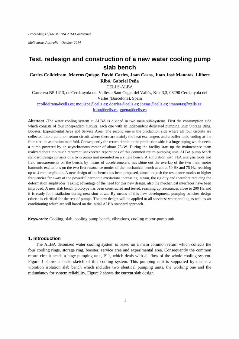
In fact the slab is quite thin, in relation of the whole slab dimensions, and it was suspect that the forced vibration excitation of the motor-pump unit deforms to much the labs or even the natural frequencies of the mechanical system based on the pumps bench slab were beaten with the asynchronous motor rotation at electrical net driving frequency. Following figure 2 shows the sketch of the design of the pumping system.
Fig. 2. a. P11 pump unit lay-out. b. Water pump slab bench design.
The pump control system has a PID feedback that adjusts the pump speed in function output pressure ensuring the system flow needed. During this period the motor driver was adjusted fix at 45Hz instead for water cooling system commissioning fact that helps to characterizes properly the pump.
Moreover the vibration induced during working condition not only damages the working pumping unit but also the redundant one.
2. Diagnose In order to figure out the problem nature two main actions were taken:
1. Check the current design under the theory point of view
3
2. Perform a vibration measurement campaign on the slab.
2. 1. Design recheck In order to figure out the stability the bench the system has been reconstructed in 3D models. This
model has full details of the steel reinforced concrete slab including the core steel reinforcement. It also includes a base steel frame on the slab top as mechanical interface where the unit is mounted. This frame is a flat rectangular shape “plate” which is empty inside. In the Figure 2. a. can be seen the concrete steel frame as well as the steel base frame between the slab and the motor-pump unit in the Figure 2. b.
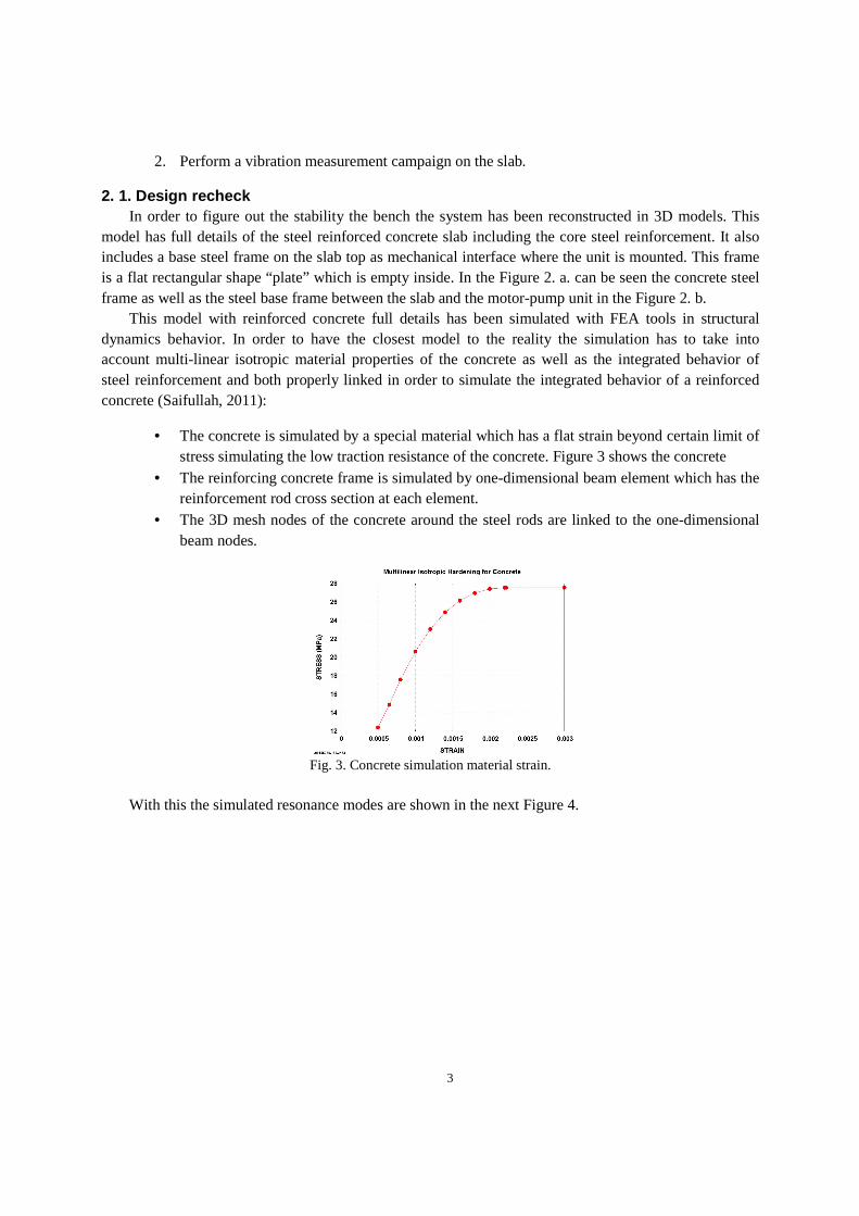
This model with reinforced concrete full details has been simulated with FEA tools in structural dynamics behavior. In order to have the closest model to the reality the simulation has to take into account multi-linear isotropic material properties of the concrete as well as the integrated behavior of steel reinforcement and both properly linked in order to simulate the integrated behavior of a reinforced concrete (Saifullah, 2011):
• The concrete is simulated by a special material which has a flat strain beyond certain limit of stress simulating the low traction resistance of the concrete. Figure 3 shows the concrete
• The reinforcing concrete frame is simulated by one-dimensional beam element which has the reinforcement rod cross section at each element.
• The 3D mesh nodes of the concrete around the steel rods are linked to the one-dimensional beam nodes.
Fig. 3. Concrete simulation material strain.
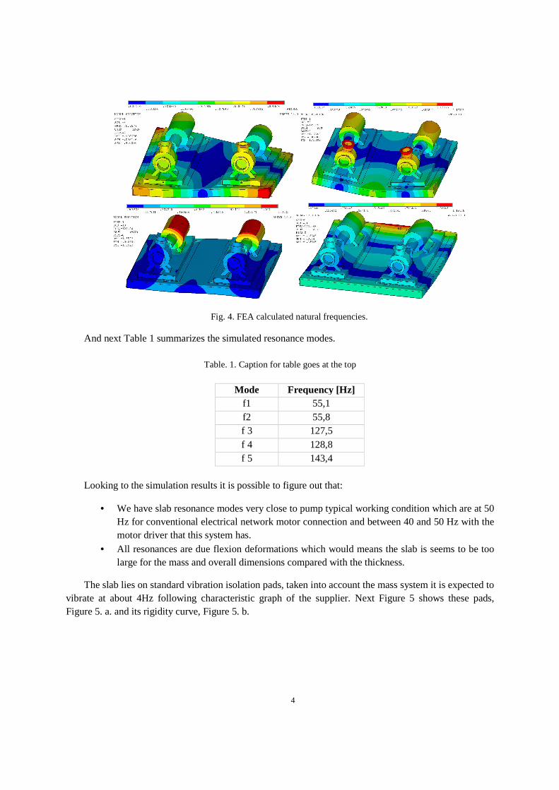
With this the simulated resonance modes are shown in the next Figure 4.
4
Fig. 4. FEA calculated natural frequencies.
And next Table 1 summarizes the simulated resonance modes.
Table. 1. Caption for table goes at the top
Mode Frequency [Hz] f1 55,1 f2 55,8 f 3 127,5 f 4 128,8 f 5 143,4
Looking to the simulation results it is possible to figure out that:
• We have slab resonance modes very close to pump typical working condition which are at 50 Hz for conventional electrical network motor connection and between 40 and 50 Hz with the motor driver that this system has.
• All resonances are due flexion deformations which would means the slab is seems to be too large for the mass and overall dimensions compared with the thickness.
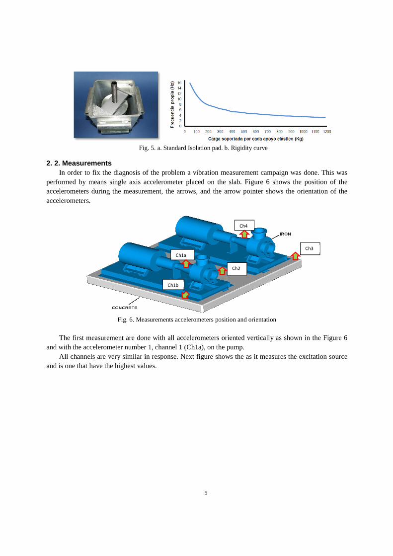
The slab lies on standard vibration isolation pads, taken into account the mass system it is expected to vibrate at about 4Hz following characteristic graph of the supplier. Next Figure 5 shows these pads, Figure 5. a. and its rigidity curve, Figure 5. b.
5
Fig. 5. a. Standard Isolation pad. b. Rigidity curve
2. 2. Measurements In order to fix the diagnosis of the problem a vibration measurement campaign was done. This was
performed by means single axis accelerometer placed on the slab. Figure 6 shows the position of the accelerometers during the measurement, the arrows, and the arrow pointer shows the orientation of the accelerometers.
Fig. 6. Measurements accelerometers position and orientation
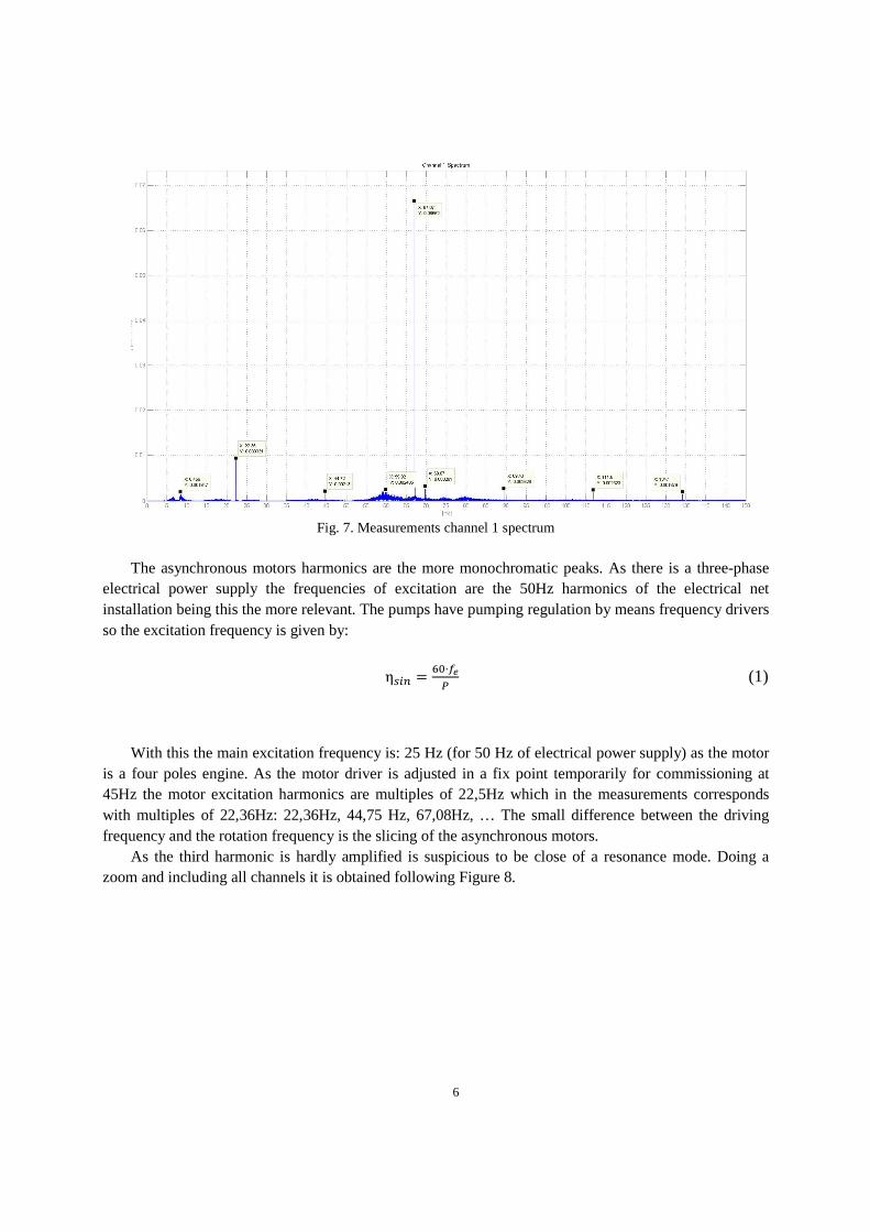
The first measurement are done with all accelerometers oriented vertically as shown in the Figure 6
and with the accelerometer number 1, channel 1 (Ch1a), on the pump. All channels are very similar in response. Next figure shows the as it measures the excitation source
and is one that have the highest values.
Ch1a
Ch2
Ch4
Ch3
Ch1b
6
Fig. 7. Measurements channel 1 spectrum
The asynchronous motors harmonics are the more monochromatic peaks. As there is a three-phase
electrical power supply the frequencies of excitation are the 50Hz harmonics of the electrical net installation being this the more relevant. The pumps have pumping regulation by means frequency drivers so the excitation frequency is given by:
�� �����
(1)
With this the main excitation frequency is: 25 Hz (for 50 Hz of electrical power supply) as the motor is a four poles engine. As the motor driver is adjusted in a fix point temporarily for commissioning at 45Hz the motor excitation harmonics are multiples of 22,5Hz which in the measurements corresponds with multiples of 22,36Hz: 22,36Hz, 44,75 Hz, 67,08Hz, … The small difference between the driving frequency and the rotation frequency is the slicing of the asynchronous motors.
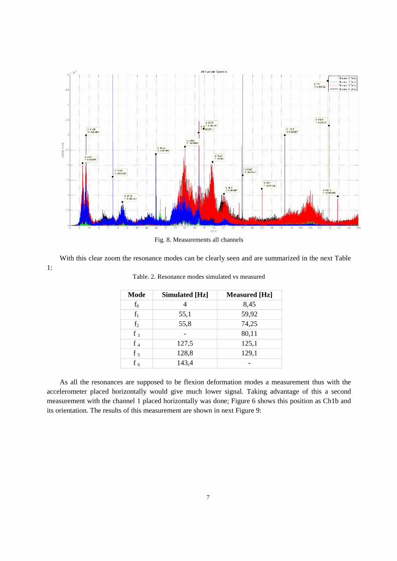
As the third harmonic is hardly amplified is suspicious to be close of a resonance mode. Doing a zoom and including all channels it is obtained following Figure 8.
7
Fig. 8. Measurements all channels
With this clear zoom the resonance modes can be clearly seen and are summarized in the next Table
1: Table. 2. Resonance modes simulated vs measured
Mode Simulated [Hz] Measured [Hz] f0 4 8,45 f1 55,1 59,92 f2 55,8 74,25 f 3 - 80,11 f 4 127,5 125,1 f 5 128,8 129,1 f 6 143,4 -
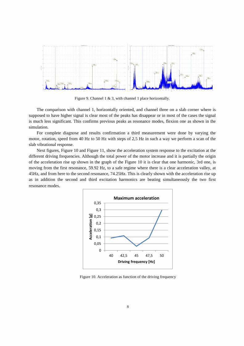
As all the resonances are supposed to be flexion deformation modes a measurement thus with the
accelerometer placed horizontally would give much lower signal. Taking advantage of this a second measurement with the channel 1 placed horizontally was done; Figure 6 shows this position as Ch1b and its orientation. The results of this measurement are shown in next Figure 9:
8
Figure 9. Channel 1 & 3, with channel 1 place horizontally.
The comparison with channel 1, horizontally oriented, and channel three on a slab corner where is
supposed to have higher signal is clear most of the peaks has disappear or in most of the cases the signal is much less significant. This confirms previous peaks as resonance modes, flexion one as shown in the simulation.
For complete diagnose and results confirmation a third measurement were done by varying the motor, rotation, speed from 40 Hz to 50 Hz with steps of 2,5 Hz in such a way we perform a scan of the slab vibrational response.
Next figures, Figure 10 and Figure 11, show the acceleration system response to the excitation at the different driving frequencies. Although the total power of the motor increase and it is partially the origin of the acceleration rise up shown in the graph of the Figure 10 it is clear that one harmonic, 3rd one, is moving from the first resonance, 59.92 Hz, to a safe regime where there is a clear acceleration valley, at 45Hz, and from here to the second resonance, 74.25Hz. This is clearly shown with the acceleration rise up as in addition the second and third excitation harmonics are beating simultaneously the two first
resonance modes.
Figure 10. Acceleration as function of the driving frequency
0
0,05
0,1
0,15
0,2
0,25
0,3
0,35
40 42,5 45 47,5 50
Acc
ele
rati
on
[g
]
Driving frequency [Hz]
Maximum acceleration
9
Figure 11. Acceleration as function of the driving frequency from 45 to 50 Hz.
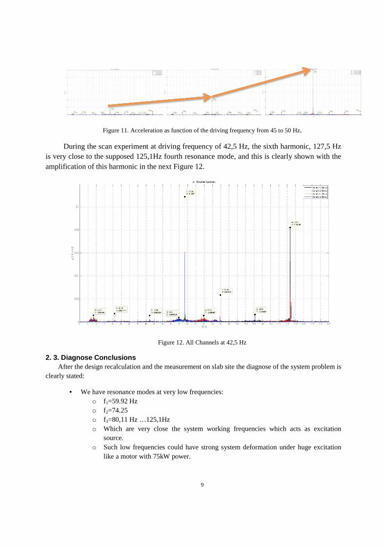
During the scan experiment at driving frequency of 42,5 Hz, the sixth harmonic, 127,5 Hz is very close to the supposed 125,1Hz fourth resonance mode, and this is clearly shown with the amplification of this harmonic in the next Figure 12.
Figure 12. All Channels at 42,5 Hz
2. 3. Diagnose Conclusions After the design recalculation and the measurement on slab site the diagnose of the system problem is
clearly stated:
• We have resonance modes at very low frequencies: o f1=59.92 Hz o f2=74.25 o f3=80,11 Hz …125,1Hz o Which are very close the system working frequencies which acts as excitation
source. o Such low frequencies could have strong system deformation under huge excitation
like a motor with 75kW power.
10
• The two first resonances are beaten simultaneously by the second and third two harmonics respectively, especially when system moves to 50 Hz which is the worst case.
• The current commissioning conditions with a fix driving frequency at 45Hz it is a relatively safe position while a final solution is implemented:
o The third excitation harmonic, 67.5 Hz, remains equidistant of two first resonance modes
o The second harmonic, 45 Hz, is far enough of the first resonance mode. o This does not allow to leave the PID work freely o The maximum acceleration is amplified by a factor of 10. From 0.03g to 0.3g when
increasing the motor speed up to 50Hz (1500min-1).
3. Slab bench redesign In order to do the new design they have been considered two main parameters:
• Split the two motors pumps base in two independent slabs o This simple change already solves the damage to the non-working
redundant pumping unit. • Increase the rigidity
o To improve still more the components life time.
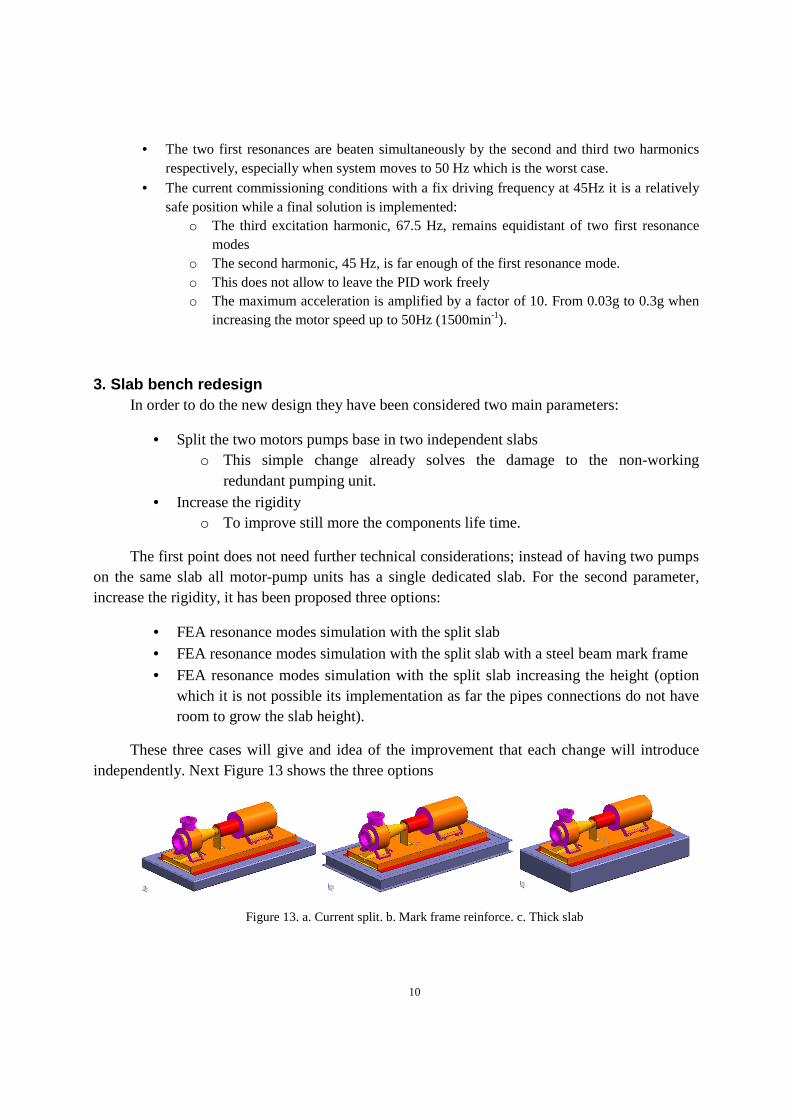
The first point does not need further technical considerations; instead of having two pumps on the same slab all motor-pump units has a single dedicated slab. For the second parameter, increase the rigidity, it has been proposed three options:
• FEA resonance modes simulation with the split slab • FEA resonance modes simulation with the split slab with a steel beam mark frame
• FEA resonance modes simulation with the split slab increasing the height (option which it is not possible its implementation as far the pipes connections do not have room to grow the slab height).
These three cases will give and idea of the improvement that each change will introduce independently. Next Figure 13 shows the three options
Figure 13. a. Current split. b. Mark frame reinforce. c. Thick slab
11
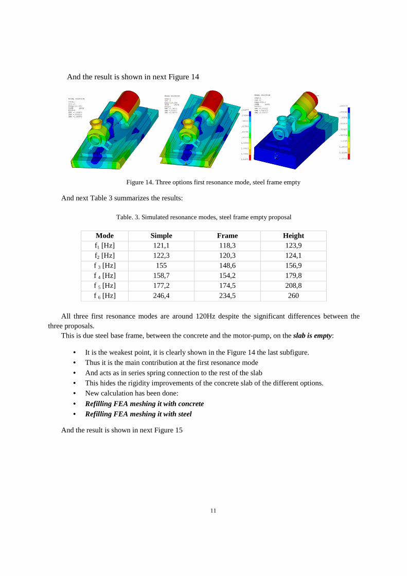
And the result is shown in next Figure 14
Figure 14. Three options first resonance mode, steel frame empty
And next Table 3 summarizes the results:
Table. 3. Simulated resonance modes, steel frame empty proposal
Mode Simple Frame Height f1 [Hz] 121,1 118,3 123,9 f2 [Hz] 122,3 120,3 124,1 f 3 [Hz] 155 148,6 156,9 f 4 [Hz] 158,7 154,2 179,8 f 5 [Hz] 177,2 174,5 208,8 f 6 [Hz] 246,4 234,5 260
All three first resonance modes are around 120Hz despite the significant differences between the
three proposals. This is due steel base frame, between the concrete and the motor-pump, on the slab is empty:
• It is the weakest point, it is clearly shown in the Figure 14 the last subfigure. • Thus it is the main contribution at the first resonance mode
• And acts as in series spring connection to the rest of the slab • This hides the rigidity improvements of the concrete slab of the different options. • New calculation has been done:
• Refilling FEA meshing it with concrete • Refilling FEA meshing it with steel
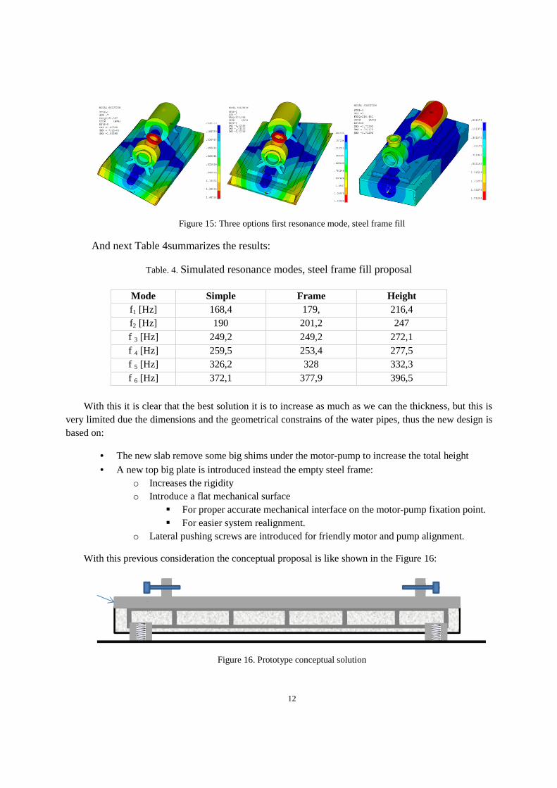
And the result is shown in next Figure 15
12
Figure 15: Three options first resonance mode, steel frame fill
And next Table 4summarizes the results:
Table. 4. Simulated resonance modes, steel frame fill proposal
Mode Simple Frame Height f1 [Hz] 168,4 179, 216,4 f2 [Hz] 190 201,2 247 f 3 [Hz] 249,2 249,2 272,1 f 4 [Hz] 259,5 253,4 277,5 f 5 [Hz] 326,2 328 332,3 f 6 [Hz] 372,1 377,9 396,5
With this it is clear that the best solution it is to increase as much as we can the thickness, but this is
very limited due the dimensions and the geometrical constrains of the water pipes, thus the new design is based on:
• The new slab remove some big shims under the motor-pump to increase the total height
• A new top big plate is introduced instead the empty steel frame: o Increases the rigidity o Introduce a flat mechanical surface
� For proper accurate mechanical interface on the motor-pump fixation point. � For easier system realignment.
o Lateral pushing screws are introduced for friendly motor and pump alignment.
With this previous consideration the conceptual proposal is like shown in the Figure 16:
Figure 16. Prototype conceptual solution
13
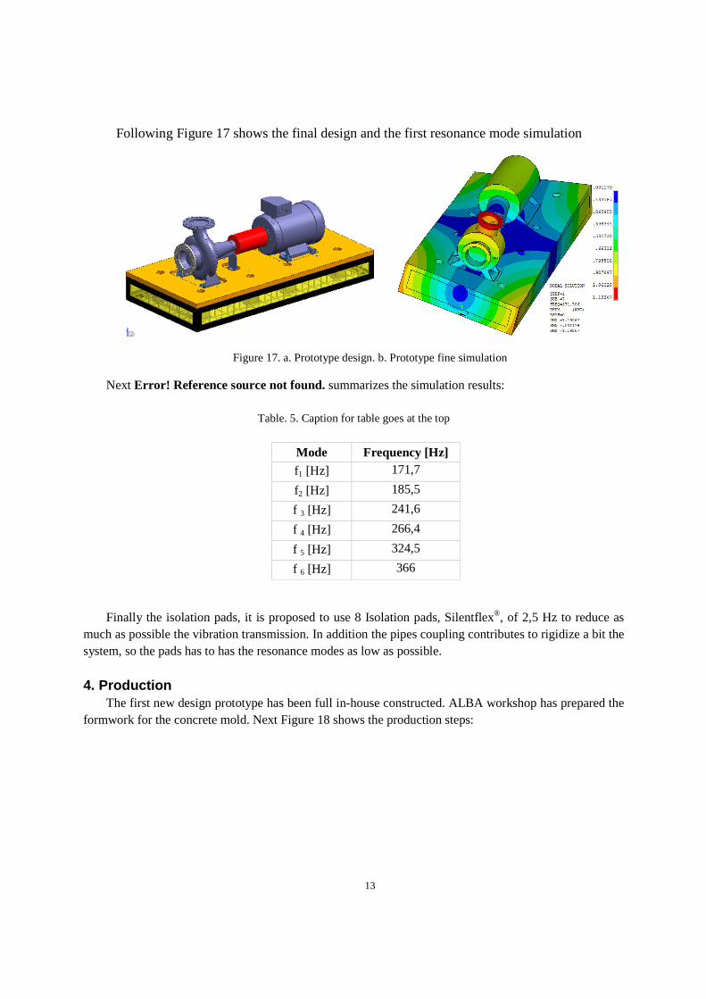
Following Figure 17 shows the final design and the first resonance mode simulation
Figure 17. a. Prototype design. b. Prototype fine simulation
Next Error! Reference source not found. summarizes the simulation results:
Table. 5. Caption for table goes at the top
Mode Frequency [Hz] f1 [Hz] 171,7
f2 [Hz] 185,5
f 3 [Hz] 241,6
f 4 [Hz] 266,4
f 5 [Hz] 324,5
f 6 [Hz] 366
Finally the isolation pads, it is proposed to use 8 Isolation pads, Silentflex®, of 2,5 Hz to reduce as much as possible the vibration transmission. In addition the pipes coupling contributes to rigidize a bit the system, so the pads has to has the resonance modes as low as possible.
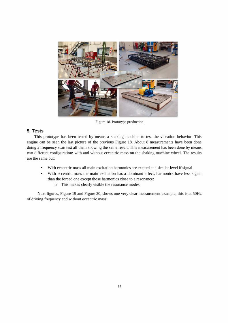
4. Production The first new design prototype has been full in-house constructed. ALBA workshop has prepared the
formwork for the concrete mold. Next Figure 18 shows the production steps:
14
Figure 18. Prototype production
5. Tests This prototype has been tested by means a shaking machine to test the vibration behavior. This
engine can be seen the last picture of the previous Figure 18. About 8 measurements have been done doing a frequency scan test all them showing the same result. This measurement has been done by means two different configuration: with and without eccentric mass on the shaking machine wheel. The results are the same but:
• With eccentric mass all main excitation harmonics are excited at a similar level if signal
• With eccentric mass the main excitation has a dominant effect, harmonics have less signal than the forced one except those harmonics close to a resonance:
o This makes clearly visible the resonance modes.
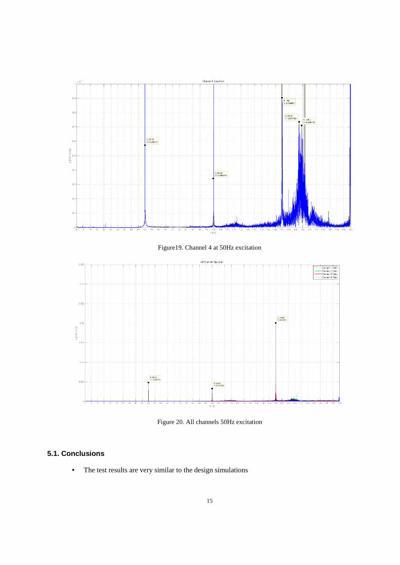
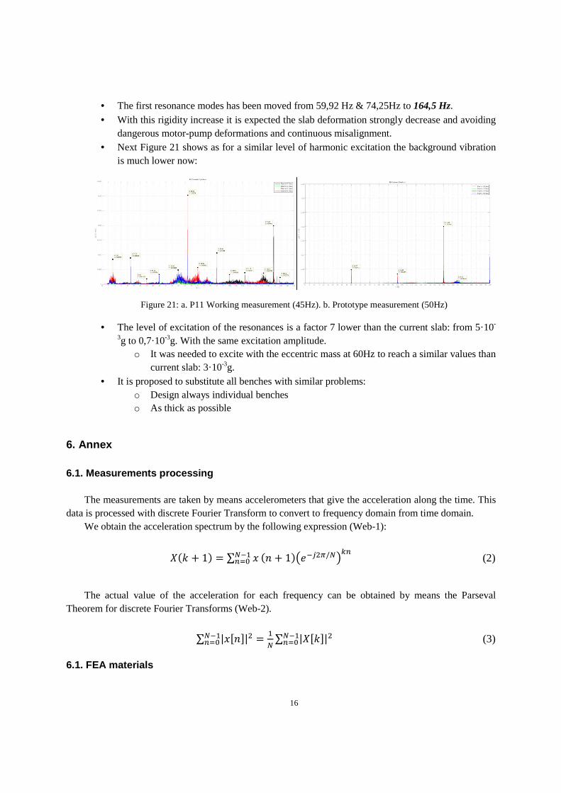
Next figures, Figure 19 and Figure 20, shows one very clear measurement example, this is at 50Hz of driving frequency and without eccentric mass:
15
Figure19. Channel 4 at 50Hz excitation
Figure 20. All channels 50Hz excitation
5.1. Conclusions
• The test results are very similar to the design simulations
16
• The first resonance modes has been moved from 59,92 Hz & 74,25Hz to 164,5 Hz. • With this rigidity increase it is expected the slab deformation strongly decrease and avoiding
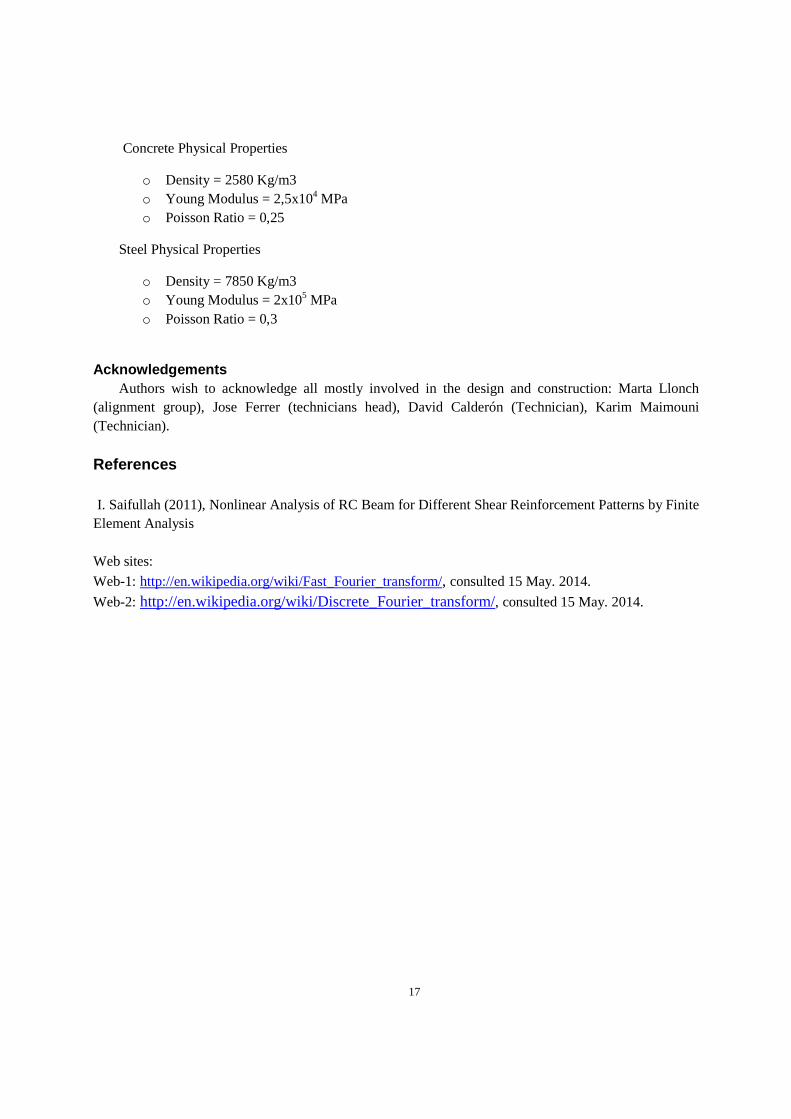
dangerous motor-pump deformations and continuous misalignment. • Next Figure 21 shows as for a similar level of harmonic excitation the background vibration
is much lower now:
Figure 21: a. P11 Working measurement (45Hz). b. Prototype measurement (50Hz)
• The level of excitation of the resonances is a factor 7 lower than the current slab: from 5·10-
3g to 0,7·10-3g. With the same excitation amplitude. o It was needed to excite with the eccentric mass at 60Hz to reach a similar values than
current slab: 3·10-3g. • It is proposed to substitute all benches with similar problems:
o Design always individual benches o As thick as possible
6. Annex 6.1. Measurements processing
The measurements are taken by means accelerometers that give the acceleration along the time. This
data is processed with discrete Fourier Transform to convert to frequency domain from time domain. We obtain the acceleration spectrum by the following expression (Web-1):
� � � 1� � ∑ ������� � � 1�������/��
� (2)
The actual value of the acceleration for each frequency can be obtained by means the Parseval
Theorem for discrete Fourier Transforms (Web-2).
∑ |�"�#|� � �
�∑ |�"�#|�������
������ (3)
6.1. FEA materials
17
Concrete Physical Properties
o Density = 2580 Kg/m3 o Young Modulus = 2,5x10⁴ MPa o Poisson Ratio = 0,25
Steel Physical Properties
o Density = 7850 Kg/m3 o Young Modulus = 2x10⁵ MPa o Poisson Ratio = 0,3
Acknowledgements
Authors wish to acknowledge all mostly involved in the design and construction: Marta Llonch (alignment group), Jose Ferrer (technicians head), David Calderón (Technician), Karim Maimouni (Technician).
References I. Saifullah (2011), Nonlinear Analysis of RC Beam for Different Shear Reinforcement Patterns by Finite Element Analysis Web sites:
Web-1: http://en.wikipedia.org/wiki/Fast_Fourier_transform/, consulted 15 May. 2014.
Web-2: http://en.wikipedia.org/wiki/Discrete_Fourier_transform/, consulted 15 May. 2014.