Speedway Cable Ladder - Ibemo Kazakhstan Ltdibemo-kz.com/LinkedDocuments/speedway_cable_lad.pdf ·...
79
Speedway Cable Ladder Total Cable Management Solutions BS-EN-ISO 9001:2000 QUALITY MANAGEMENT SYSTEM ibemo Kazakhstan - 090301 Republic of Kazakhstan, West Kazakhstan Oblast, Aksai, Pramzone, BKKS office complex Phone: +7 71133 93077; Fax: +7 71133 93074; E-Mail: [email protected]; http://www.ibemo.kz ibemo I N D U S T R I A L & E L E C T R I C A L E Q U I P M E N T
Transcript of Speedway Cable Ladder - Ibemo Kazakhstan Ltdibemo-kz.com/LinkedDocuments/speedway_cable_lad.pdf ·...
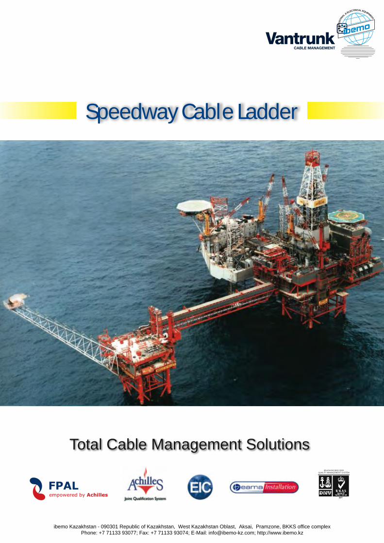
Speedway Cable Ladder
Total Cable Management SolutionsBS-EN-ISO 9001:2000
QUALITY MANAGEMENT SYSTEM
ibemo Kazakhstan - 090301 Republic of Kazakhstan, West Kazakhstan Oblast, Aksai, Pramzone, BKKS office complex Phone: +7 71133 93077; Fax: +7 71133 93074; E-Mail: [email protected]; http://www.ibemo.kz
ibemoIND
USTR
IA
L & ELECTRICAL EQUIPMENT
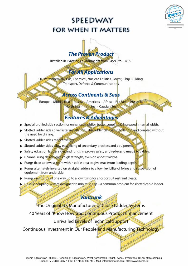
The Proven ProductInstalled in Exacting Environments from -45°C to +45°C
For All ApplicationsOil, Petrochemical, Gas, Chemical, Nuclear, Utilities, Power, Ship Building,
Transport, Defence & Communications
Across Continents & SeasEurope . Middle East . Russia . Americas . Africa . Far East . Australia
North Sea . Irish Sea . Caspian Sea
Features & Advantages . Special profiled side section for enhanced rigidity, better coupling & increased internal width.
. Slotted ladder sides give faster installation. The ladder can be cut to length and coupled without the need for drilling.
. Slotted ladder sides reduce weight.
. Slotted ladder sides allow easy fixing of secondary brackets and equipment.
. Safety edges on ladder sides and rungs improves safety and reduces damage to cables.
. Channel rung design gives high strength, even on widest widths.
. Rungs fixed at lowest point within cable area to give maximum loading depth.
. Rungs alternately inverted on straight ladders to allow flexibility of fixing and suspension of equipment from underside.
. Rungs on fittings all one way up to allow fixing for short circuit restraint cleats.
. Unique coupling system designed to minimise slip – a common problem for slotted cable ladder.
VantrunkThe Original UK Manufacturer of Cable Ladder Systems
40 Years of ‘Know How’ and Continuous Product Enhancement
Unrivalled Levels of Technical Support
Continuous Investment in Our People and Manufacturing Technology
SPEEDWAYfor when it matters
ibemo Kazakhstan - 090301 Republic of Kazakhstan, West Kazakhstan Oblast, Aksai, Pramzone, BKKS office complex Phone: +7 71133 93077; Fax: +7 71133 93074; E-Mail: [email protected]; http://www.ibemo.kz
ibemoIND
USTR
IA
L & ELECTRICAL EQUIPMENT
1
to
ta
l c
ab
le m
an
ag
em
en
t s
olu
tio
ns
Introduction
Product Range
Speedway Cable Ladder System
Speedway Part Number Guide
Speedway Straight Cable Ladder
Speedway Couplers
Speedway Long Span Ladder
Speedway Cross-braced Ladder
Speedway Flat Elbows
Speedway Risers
Speedway Articulated Risers
Speedway Equal & Unequal Tees
Speedway Crosses
Speedway Reducers
Speedway Accessories
Speedway Supports
Speedway Covers
Fixings
Technical Data
Conversion Factors for Units
1-3
4-5
6-7
8
9-10
11-15
16
17-18
19-21
22-24
25-26
27-30
31-32
33-34
35-45
46-52
53-54
55-56
57-75
76
Contents
Page Contents
Total Cable Management SolutionsBS-EN-ISO 9001:2000
QUALITY MANAGEMENT SYSTEM
Cable Tray
Total Cable Management SolutionsBS-EN-ISO 9001:2000
QUALITY MANAGEMENT SYSTEM
Steel Framing
Other Vantrunk catalogues
ibemo Kazakhstan - 090301 Republic of Kazakhstan, West Kazakhstan Oblast, Aksai, Pramzone, BKKS office complex Phone: +7 71133 93077; Fax: +7 71133 93074; E-Mail: [email protected]; http://www.ibemo.kz
ibemoIND
USTR
IA
L & ELECTRICAL EQUIPMENT
1
to
ta
l c
ab
le m
an
ag
em
en
t s
olu
tio
ns
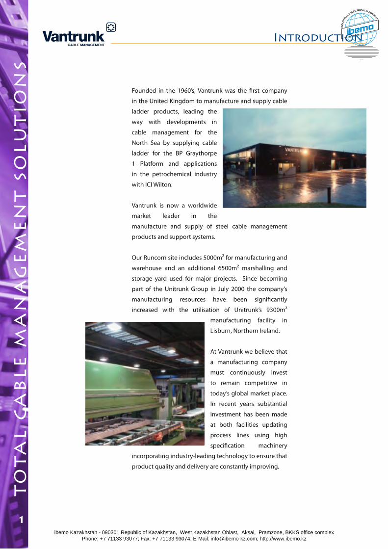
Founded in the 1960’s, Vantrunk was the first company
in the United Kingdom to manufacture and supply cable
ladder products, leading the
way with developments in
cable management for the
North Sea by supplying cable
ladder for the BP Graythorpe
1 Platform and applications
in the petrochemical industry
with ICI Wilton.
Vantrunk is now a worldwide
market leader in the
manufacture and supply of steel cable management
products and support systems.
Our Runcorn site includes 5000m² for manufacturing and
warehouse and an additional 6500m² marshalling and
storage yard used for major projects. Since becoming
part of the Unitrunk Group in July 2000 the company’s
manufacturing resources have been significantly
increased with the utilisation of Unitrunk’s 9300m²
manufacturing facility in
Lisburn, Northern Ireland.
At Vantrunk we believe that
a manufacturing company
must continuously invest
to remain competitive in
today’s global market place.
In recent years substantial
investment has been made
at both facilities updating
process lines using high
specification machinery
incorporating industry-leading technology to ensure that
product quality and delivery are constantly improving.
Introduction
ibemo Kazakhstan - 090301 Republic of Kazakhstan, West Kazakhstan Oblast, Aksai, Pramzone, BKKS office complex Phone: +7 71133 93077; Fax: +7 71133 93074; E-Mail: [email protected]; http://www.ibemo.kz
ibemoIND
USTR
IA
L & ELECTRICAL EQUIPMENT
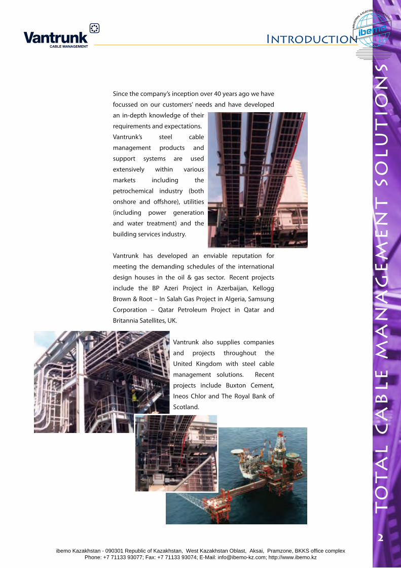
Since the company’s inception over 40 years ago we have
focussed on our customers’ needs and have developed
an in-depth knowledge of their
requirements and expectations.
Vantrunk’s steel cable
management products and
support systems are used
extensively within various
markets including the
petrochemical industry (both
onshore and offshore), utilities
(including power generation
and water treatment) and the
building services industry.
Vantrunk has developed an enviable reputation for
meeting the demanding schedules of the international
design houses in the oil & gas sector. Recent projects
include the BP Azeri Project in Azerbaijan, Kellogg
Brown & Root – In Salah Gas Project in Algeria, Samsung
Corporation – Qatar Petroleum Project in Qatar and
Britannia Satellites, UK.
Vantrunk also supplies companies
and projects throughout the
United Kingdom with steel cable
management solutions. Recent
projects include Buxton Cement,
Ineos Chlor and The Royal Bank of
Scotland.
Introduction
3
to
ta
l c
ab
le m
an
ag
em
en
t s
olu
tio
ns
2ibemo Kazakhstan - 090301 Republic of Kazakhstan, West Kazakhstan Oblast, Aksai, Pramzone, BKKS office complex Phone: +7 71133 93077; Fax: +7 71133 93074; E-Mail: [email protected]; http://www.ibemo.kz
ibemoIND
USTR
IA
L & ELECTRICAL EQUIPMENT
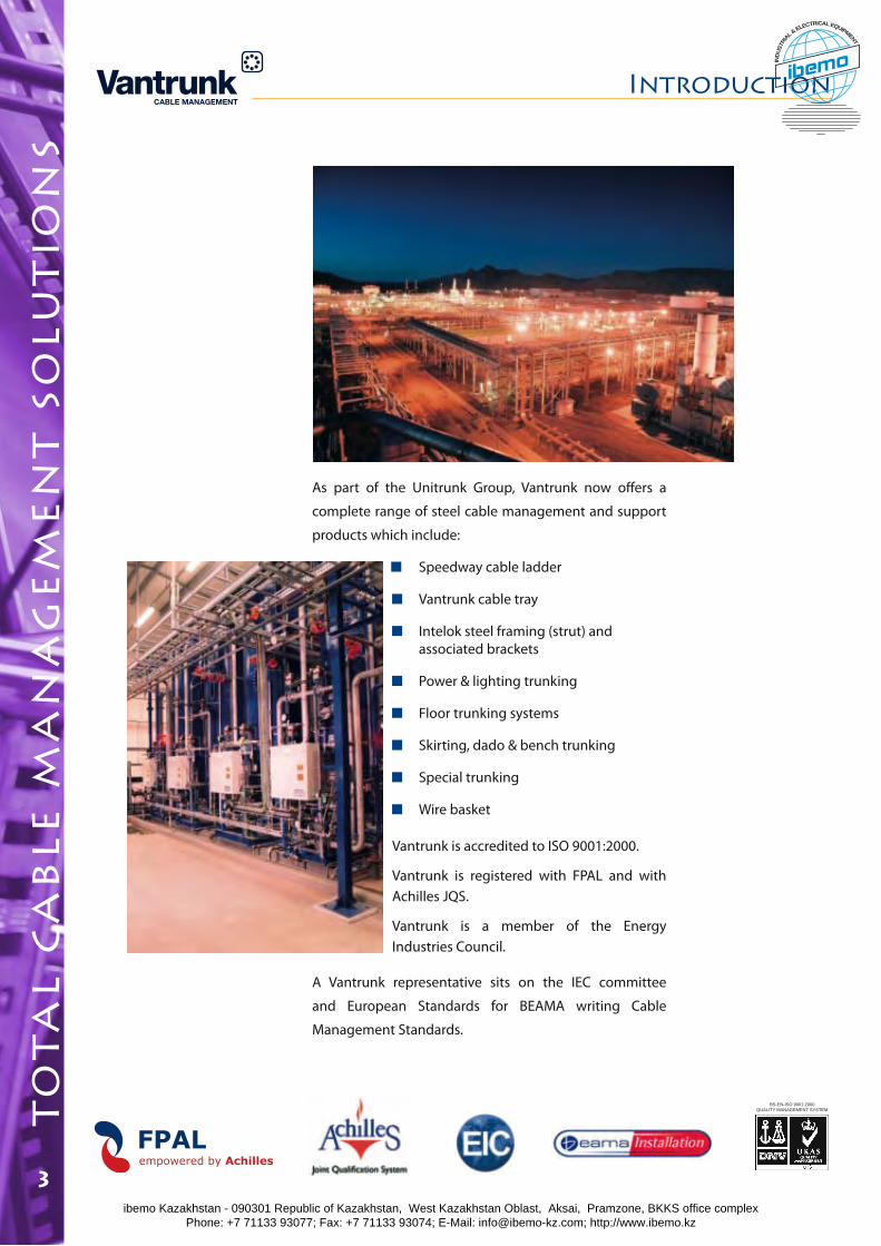
As part of the Unitrunk Group, Vantrunk now offers a
complete range of steel cable management and support
products which include:
Speedway cable ladder
Vantrunk cable tray
Intelok steel framing (strut) and associated brackets
Power & lighting trunking
Floor trunking systems
Skirting, dado & bench trunking
Special trunking
Wire basket
Vantrunk is accredited to ISO 9001:2000.
Vantrunk is registered with FPAL and with Achilles JQS.
Vantrunk is a member of the Energy Industries Council.
A Vantrunk representative sits on the IEC committee
and European Standards for BEAMA writing Cable
Management Standards.
Introduction
2
to
ta
l c
ab
le m
an
ag
em
en
t s
olu
tio
ns
3
BS-EN-ISO 9001:2000QUALITY MANAGEMENT SYSTEM
ibemo Kazakhstan - 090301 Republic of Kazakhstan, West Kazakhstan Oblast, Aksai, Pramzone, BKKS office complex Phone: +7 71133 93077; Fax: +7 71133 93074; E-Mail: [email protected]; http://www.ibemo.kz
ibemoIND
USTR
IA
L & ELECTRICAL EQUIPMENT
pr
od
uc
t r
an
ge
4
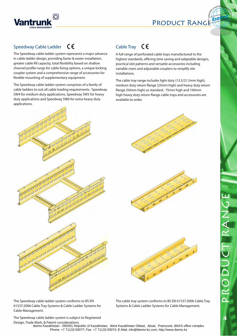
Speedway Cable LadderThe Speedway cable ladder system represents a major advance in cable ladder design, providing faster & easier installation, greater cable fill capacity, total flexibility based on shallow channel profile rungs for cable fixing options, a unique locking coupler system and a comprehensive range of accessories for flexible mounting of supplementary equipment.
The Speedway cable ladder system comprises of a family of cable ladders to suit all cable loading requirements. Speedway SW4 for medium duty applications, Speedway SW5 for heavy duty applications and Speedway SW6 for extra-heavy duty applications.
Cable TrayA full range of perforated cable trays manufactured to the highest standards, offering time saving and adaptable designs, practical slot patterns and versatile accessories including variable risers and adjustable couplers to simplify site installations.
The cable tray range includes light duty (13.5/21.5mm high), medium duty return flange (25mm high) and heavy duty return flange (50mm high) as standard. 75mm high and 100mm high heavy duty return flange cable trays and accessories are available to order.
Product Range
The Speedway cable ladder system conforms to BS EN 61537:2006 Cable Tray Systems & Cable Ladder Systems for Cable Management.
The Speedway cable ladder system is subject to Registered Design, Trade Mark, & Patent considerations.
The cable tray system conforms to BS EN 61537:2006 Cable Tray Systems & Cable Ladder Systems for Cable Management.
ibemo Kazakhstan - 090301 Republic of Kazakhstan, West Kazakhstan Oblast, Aksai, Pramzone, BKKS office complex Phone: +7 71133 93077; Fax: +7 71133 93074; E-Mail: [email protected]; http://www.ibemo.kz
ibemoIND
USTR
IA
L & ELECTRICAL EQUIPMENT
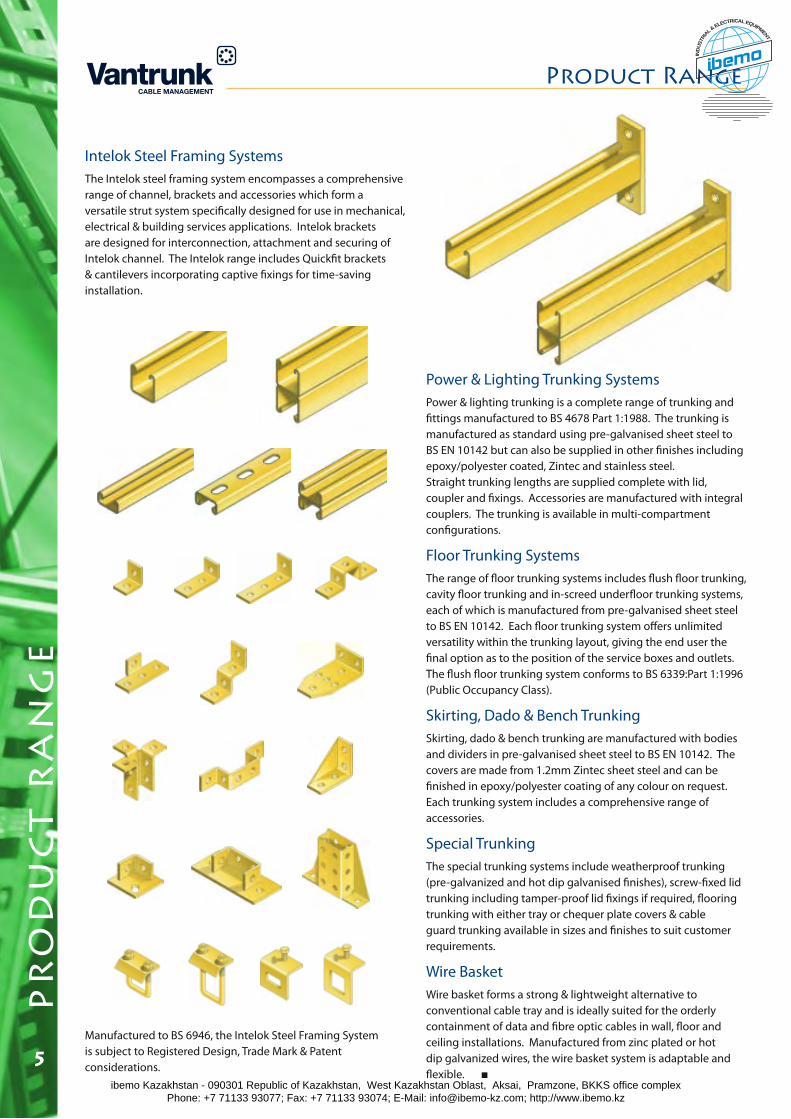
Intelok Steel Framing SystemsThe Intelok steel framing system encompasses a comprehensive range of channel, brackets and accessories which form a versatile strut system specifically designed for use in mechanical, electrical & building services applications. Intelok brackets are designed for interconnection, attachment and securing of Intelok channel. The Intelok range includes Quickfit brackets & cantilevers incorporating captive fixings for time-saving installation.
Power & Lighting Trunking SystemsPower & lighting trunking is a complete range of trunking and fittings manufactured to BS 4678 Part 1:1988. The trunking is manufactured as standard using pre-galvanised sheet steel to BS EN 10142 but can also be supplied in other finishes including epoxy/polyester coated, Zintec and stainless steel. Straight trunking lengths are supplied complete with lid, coupler and fixings. Accessories are manufactured with integral couplers. The trunking is available in multi-compartment configurations.
Floor Trunking SystemsThe range of floor trunking systems includes flush floor trunking, cavity floor trunking and in-screed underfloor trunking systems, each of which is manufactured from pre-galvanised sheet steel to BS EN 10142. Each floor trunking system offers unlimited versatility within the trunking layout, giving the end user the final option as to the position of the service boxes and outlets. The flush floor trunking system conforms to BS 6339:Part 1:1996 (Public Occupancy Class).
Skirting, Dado & Bench TrunkingSkirting, dado & bench trunking are manufactured with bodies and dividers in pre-galvanised sheet steel to BS EN 10142. The covers are made from 1.2mm Zintec sheet steel and can be finished in epoxy/polyester coating of any colour on request. Each trunking system includes a comprehensive range of accessories.
Special TrunkingThe special trunking systems include weatherproof trunking (pre-galvanized and hot dip galvanised finishes), screw-fixed lid trunking including tamper-proof lid fixings if required, flooring trunking with either tray or chequer plate covers & cable guard trunking available in sizes and finishes to suit customer requirements.
Wire BasketWire basket forms a strong & lightweight alternative to conventional cable tray and is ideally suited for the orderly containment of data and fibre optic cables in wall, floor and ceiling installations. Manufactured from zinc plated or hot dip galvanized wires, the wire basket system is adaptable and flexible.
Product Range
Manufactured to BS 6946, the Intelok Steel Framing System is subject to Registered Design, Trade Mark & Patent considerations.
pr
od
uc
t r
an
ge
5ibemo Kazakhstan - 090301 Republic of Kazakhstan, West Kazakhstan Oblast, Aksai, Pramzone, BKKS office complex Phone: +7 71133 93077; Fax: +7 71133 93074; E-Mail: [email protected]; http://www.ibemo.kz
ibemoIND
USTR
IA
L & ELECTRICAL EQUIPMENT
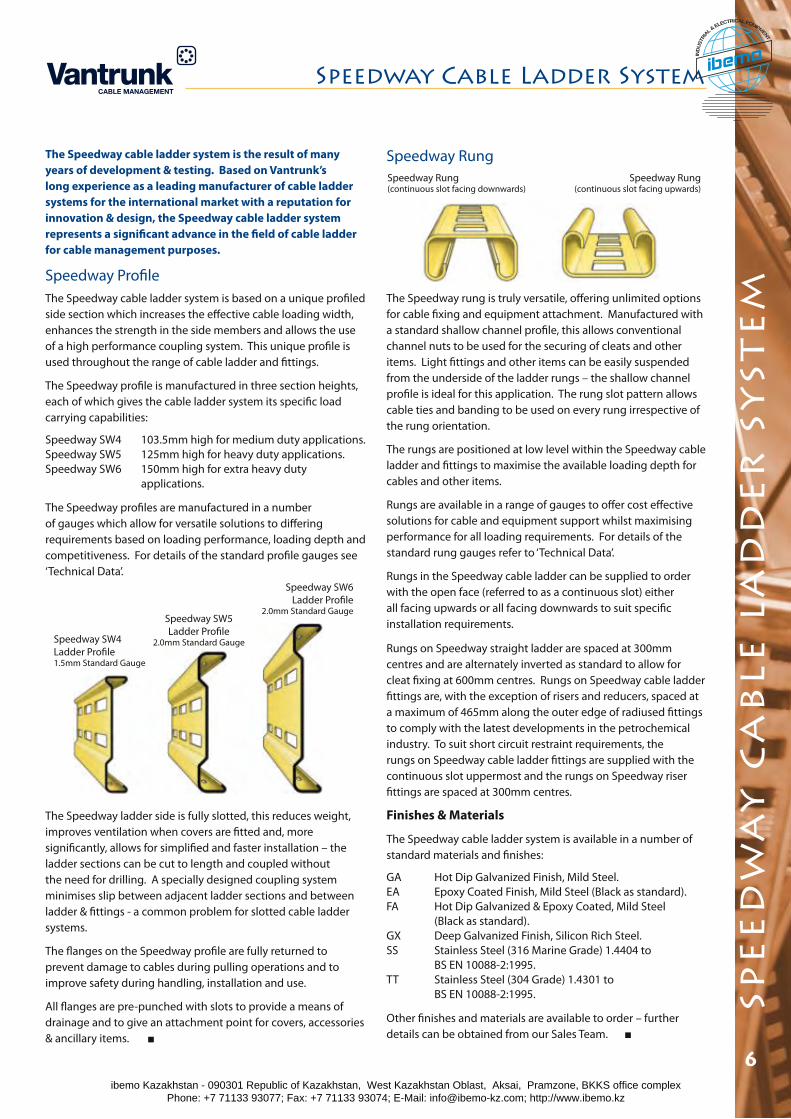
Speedway Rung
The Speedway rung is truly versatile, offering unlimited options for cable fixing and equipment attachment. Manufactured with a standard shallow channel profile, this allows conventional channel nuts to be used for the securing of cleats and other items. Light fittings and other items can be easily suspended from the underside of the ladder rungs – the shallow channel profile is ideal for this application. The rung slot pattern allows cable ties and banding to be used on every rung irrespective of the rung orientation.
The rungs are positioned at low level within the Speedway cable ladder and fittings to maximise the available loading depth for cables and other items.
Rungs are available in a range of gauges to offer cost effective solutions for cable and equipment support whilst maximising performance for all loading requirements. For details of the standard rung gauges refer to ‘Technical Data’.
Rungs in the Speedway cable ladder can be supplied to order with the open face (referred to as a continuous slot) either all facing upwards or all facing downwards to suit specific installation requirements.
Rungs on Speedway straight ladder are spaced at 300mm centres and are alternately inverted as standard to allow for cleat fixing at 600mm centres. Rungs on Speedway cable ladder fittings are, with the exception of risers and reducers, spaced at a maximum of 465mm along the outer edge of radiused fittings to comply with the latest developments in the petrochemical industry. To suit short circuit restraint requirements, the rungs on Speedway cable ladder fittings are supplied with the continuous slot uppermost and the rungs on Speedway riser fittings are spaced at 300mm centres.
Finishes & Materials
The Speedway cable ladder system is available in a number of standard materials and finishes:
GA Hot Dip Galvanized Finish, Mild Steel.EA Epoxy Coated Finish, Mild Steel (Black as standard).FA Hot Dip Galvanized & Epoxy Coated, Mild Steel (Black as standard).GX Deep Galvanized Finish, Silicon Rich Steel.SS Stainless Steel (316 Marine Grade) 1.4404 to BS EN 10088-2:1995.TT Stainless Steel (304 Grade) 1.4301 to BS EN 10088-2:1995.
Other finishes and materials are available to order – further details can be obtained from our Sales Team.
Speedway Cable Ladder System
The Speedway cable ladder system is the result of many years of development & testing. Based on Vantrunk’s long experience as a leading manufacturer of cable ladder systems for the international market with a reputation for innovation & design, the Speedway cable ladder system represents a significant advance in the field of cable ladder for cable management purposes.
Speedway ProfileThe Speedway cable ladder system is based on a unique profiled side section which increases the effective cable loading width, enhances the strength in the side members and allows the use of a high performance coupling system. This unique profile is used throughout the range of cable ladder and fittings.
The Speedway profile is manufactured in three section heights, each of which gives the cable ladder system its specific load carrying capabilities:
Speedway SW4 103.5mm high for medium duty applications.Speedway SW5 125mm high for heavy duty applications.Speedway SW6 150mm high for extra heavy duty applications.
The Speedway profiles are manufactured in a number of gauges which allow for versatile solutions to differing requirements based on loading performance, loading depth and competitiveness. For details of the standard profile gauges see ‘Technical Data’.
Speedway SW4 Ladder Profile1.5mm Standard Gauge
Speedway SW5Ladder Profile
2.0mm Standard Gauge
Speedway SW6Ladder Profile
2.0mm Standard Gauge
The Speedway ladder side is fully slotted, this reduces weight, improves ventilation when covers are fitted and, more significantly, allows for simplified and faster installation – the ladder sections can be cut to length and coupled without the need for drilling. A specially designed coupling system minimises slip between adjacent ladder sections and between ladder & fittings - a common problem for slotted cable ladder systems.
The flanges on the Speedway profile are fully returned to prevent damage to cables during pulling operations and to improve safety during handling, installation and use.
All flanges are pre-punched with slots to provide a means of drainage and to give an attachment point for covers, accessories & ancillary items.
Speedway Rung (continuous slot facing downwards)
Speedway Rung (continuous slot facing upwards)
spe
ed
wa
y c
ab
le l
ad
de
r s
yst
em
6ibemo Kazakhstan - 090301 Republic of Kazakhstan, West Kazakhstan Oblast, Aksai, Pramzone, BKKS office complex Phone: +7 71133 93077; Fax: +7 71133 93074; E-Mail: [email protected]; http://www.ibemo.kz
ibemoIND
USTR
IA
L & ELECTRICAL EQUIPMENT
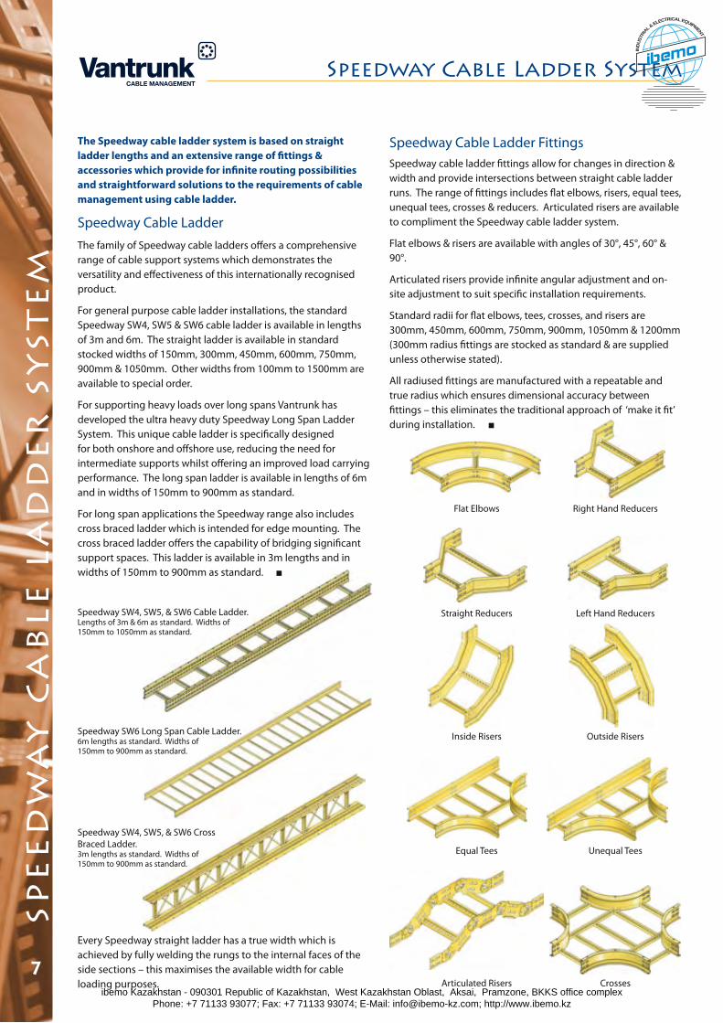
Speedway SW4, SW5, & SW6 Cable Ladder. Lengths of 3m & 6m as standard. Widths of 150mm to 1050mm as standard.
Speedway SW6 Long Span Cable Ladder. 6m lengths as standard. Widths of150mm to 900mm as standard.
Speedway SW4, SW5, & SW6 Cross Braced Ladder. 3m lengths as standard. Widths of 150mm to 900mm as standard.
Every Speedway straight ladder has a true width which is achieved by fully welding the rungs to the internal faces of the side sections – this maximises the available width for cable loading purposes.
Speedway Cable Ladder System
The Speedway cable ladder system is based on straight ladder lengths and an extensive range of fittings & accessories which provide for infinite routing possibilities and straightforward solutions to the requirements of cable management using cable ladder.
Speedway Cable LadderThe family of Speedway cable ladders offers a comprehensive range of cable support systems which demonstrates the versatility and effectiveness of this internationally recognised product.
For general purpose cable ladder installations, the standard Speedway SW4, SW5 & SW6 cable ladder is available in lengths of 3m and 6m. The straight ladder is available in standard stocked widths of 150mm, 300mm, 450mm, 600mm, 750mm, 900mm & 1050mm. Other widths from 100mm to 1500mm are available to special order.
For supporting heavy loads over long spans Vantrunk has developed the ultra heavy duty Speedway Long Span Ladder System. This unique cable ladder is specifically designed for both onshore and offshore use, reducing the need for intermediate supports whilst offering an improved load carrying performance. The long span ladder is available in lengths of 6m and in widths of 150mm to 900mm as standard.
For long span applications the Speedway range also includes cross braced ladder which is intended for edge mounting. The cross braced ladder offers the capability of bridging significant support spaces. This ladder is available in 3m lengths and in widths of 150mm to 900mm as standard.
Speedway Cable Ladder FittingsSpeedway cable ladder fittings allow for changes in direction & width and provide intersections between straight cable ladder runs. The range of fittings includes flat elbows, risers, equal tees, unequal tees, crosses & reducers. Articulated risers are available to compliment the Speedway cable ladder system.
Flat elbows & risers are available with angles of 30°, 45°, 60° & 90°.
Articulated risers provide infinite angular adjustment and on-site adjustment to suit specific installation requirements.
Standard radii for flat elbows, tees, crosses, and risers are 300mm, 450mm, 600mm, 750mm, 900mm, 1050mm & 1200mm (300mm radius fittings are stocked as standard & are supplied unless otherwise stated).
All radiused fittings are manufactured with a repeatable and true radius which ensures dimensional accuracy between fittings – this eliminates the traditional approach of ‘make it fit’ during installation.
Right Hand ReducersFlat Elbows
Left Hand Reducers
Inside Risers
Unequal TeesEqual Tees
Straight Reducers
spe
ed
wa
y c
ab
le l
ad
de
r s
yst
em
7Articulated Risers Crosses
Outside Risers
ibemo Kazakhstan - 090301 Republic of Kazakhstan, West Kazakhstan Oblast, Aksai, Pramzone, BKKS office complex Phone: +7 71133 93077; Fax: +7 71133 93074; E-Mail: [email protected]; http://www.ibemo.kz
ibemoIND
USTR
IA
L & ELECTRICAL EQUIPMENT
Page
Page
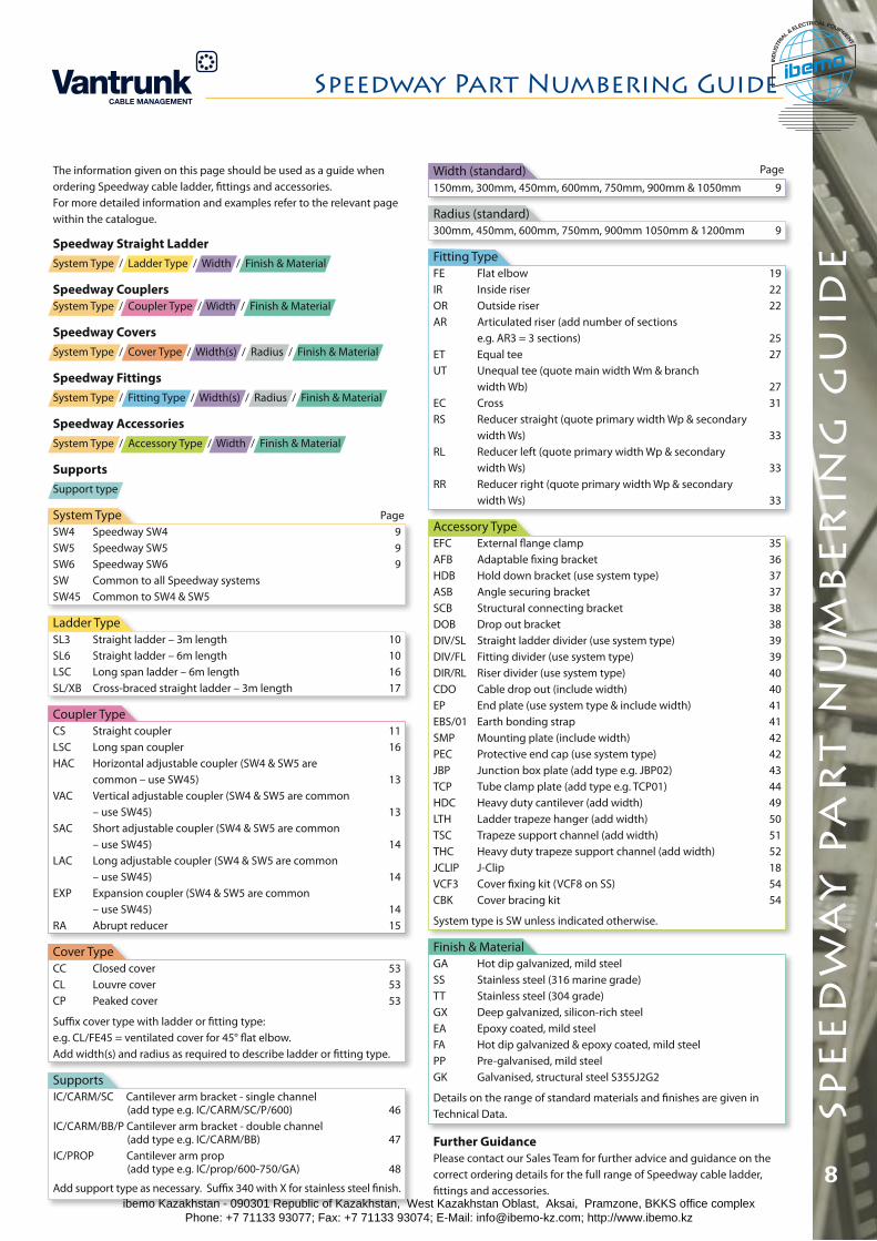
Speedway Part Numbering Guide
Width (standard)150mm, 300mm, 450mm, 600mm, 750mm, 900mm & 1050mm 9
Radius (standard)300mm, 450mm, 600mm, 750mm, 900mm 1050mm & 1200mm 9
Fitting TypeFE Flat elbow 19IR Inside riser 22OR Outside riser 22AR Articulated riser (add number of sections e.g. AR3 = 3 sections) 25ET Equal tee 27UT Unequal tee (quote main width Wm & branch width Wb) 27EC Cross 31RS Reducer straight (quote primary width Wp & secondary width Ws) 33RL Reducer left (quote primary width Wp & secondary width Ws) 33RR Reducer right (quote primary width Wp & secondary width Ws) 33
Accessory TypeEFC External flange clamp 35AFB Adaptable fixing bracket 36HDB Hold down bracket (use system type) 37ASB Angle securing bracket 37SCB Structural connecting bracket 38DOB Drop out bracket 38DIV/SL Straight ladder divider (use system type) 39DIV/FL Fitting divider (use system type) 39DIR/RL Riser divider (use system type) 40CDO Cable drop out (include width) 40EP End plate (use system type & include width) 41EBS/01 Earth bonding strap 41SMP Mounting plate (include width) 42PEC Protective end cap (use system type) 42JBP Junction box plate (add type e.g. JBP02) 43TCP Tube clamp plate (add type e.g. TCP01) 44HDC Heavy duty cantilever (add width) 49LTH Ladder trapeze hanger (add width) 50TSC Trapeze support channel (add width) 51THC Heavy duty trapeze support channel (add width) 52JCLIP J-Clip 18VCF3 Cover fixing kit (VCF8 on SS) 54CBK Cover bracing kit 54
System type is SW unless indicated otherwise.
Finish & MaterialGA Hot dip galvanized, mild steelSS Stainless steel (316 marine grade)TT Stainless steel (304 grade)GX Deep galvanized, silicon-rich steelEA Epoxy coated, mild steelFA Hot dip galvanized & epoxy coated, mild steelPP Pre-galvanised, mild steelGK Galvanised, structural steel S355J2G2
Details on the range of standard materials and finishes are given inTechnical Data.
Further GuidancePlease contact our Sales Team for further advice and guidance on the correct ordering details for the full range of Speedway cable ladder, fittings and accessories.
The information given on this page should be used as a guide when ordering Speedway cable ladder, fittings and accessories.For more detailed information and examples refer to the relevant page within the catalogue.
Speedway Straight LadderSystem Type / Ladder Type / Width / Finish & Material
Speedway CouplersSystem Type / Coupler Type / Width / Finish & Material
Speedway CoversSystem Type / Cover Type / Width(s) / Radius / Finish & Material
Speedway FittingsSystem Type / Fitting Type / Width(s) / Radius / Finish & Material
Speedway AccessoriesSystem Type / Accessory Type / Width / Finish & Material
SupportsSupport type
System TypeSW4 Speedway SW4 9SW5 Speedway SW5 9SW6 Speedway SW6 9SW Common to all Speedway systemsSW45 Common to SW4 & SW5
Ladder TypeSL3 Straight ladder – 3m length 10SL6 Straight ladder – 6m length 10LSC Long span ladder – 6m length 16SL/XB Cross-braced straight ladder – 3m length 17
Coupler TypeCS Straight coupler 11LSC Long span coupler 16HAC Horizontal adjustable coupler (SW4 & SW5 are common – use SW45) 13VAC Vertical adjustable coupler (SW4 & SW5 are common – use SW45) 13SAC Short adjustable coupler (SW4 & SW5 are common – use SW45) 14LAC Long adjustable coupler (SW4 & SW5 are common – use SW45) 14EXP Expansion coupler (SW4 & SW5 are common – use SW45) 14RA Abrupt reducer 15
Cover TypeCC Closed cover 53CL Louvre cover 53CP Peaked cover 53
Suffix cover type with ladder or fitting type: e.g. CL/FE45 = ventilated cover for 45° flat elbow.Add width(s) and radius as required to describe ladder or fitting type.
SupportsIC/CARM/SC Cantilever arm bracket - single channel (add type e.g. IC/CARM/SC/P/600) 46IC/CARM/BB/P Cantilever arm bracket - double channel (add type e.g. IC/CARM/BB) 47IC/PROP Cantilever arm prop (add type e.g. IC/prop/600-750/GA) 48
Add support type as necessary. Suffix 340 with X for stainless steel finish.
spe
ed
wa
y p
ar
t n
um
be
rin
g g
uid
e
8ibemo Kazakhstan - 090301 Republic of Kazakhstan, West Kazakhstan Oblast, Aksai, Pramzone, BKKS office complex Phone: +7 71133 93077; Fax: +7 71133 93074; E-Mail: [email protected]; http://www.ibemo.kz
ibemoIND
USTR
IA
L & ELECTRICAL EQUIPMENT
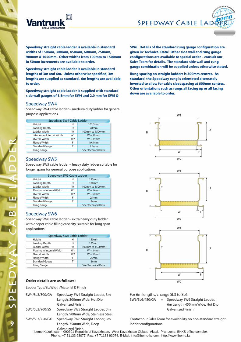
Speedway SW5Speedway SW5 cable ladder – heavy duty ladder suitable for longer spans for general purpose applications.
Speedway SW6Speedway SW6 cable ladder – extra heavy duty ladder with deeper cable filling capacity, suitable for long span applications.
Height H 103.5mmLoading Depth D 78mmLadder Width W 100mm to 1500mm Maximum Internal Width W1 W + 10mmOverall Width W2 W + 39mmFlange Width F 19.5mmStandard Gauge T 1.5mmRung Gauge See ‘Technical Data’
9
spe
ed
wa
y c
ab
le l
ad
de
rSpeedway Cable Ladder
Speedway straight cable ladder is available in standard widths of 150mm, 300mm, 450mm, 600mm, 750mm, 900mm & 1050mm. Other widths from 100mm to 1500mm in 50mm increments are available to order.
Speedway straight cable ladder is available in standard lengths of 3m and 6m. Unless otherwise specified, 3m lengths are supplied as standard. 6m lengths are available to order.
Speedway straight cable ladder is supplied with standard side wall gauges of 1.5mm for SW4 and 2.0 mm for SW5 &
Height H 150mmLoading Depth D 125mmLadder Width W 100mm to 1500mmMaximum Internal Width W1 W + 14mmOverall Width W2 W + 50mmFlange Width F 25mmStandard Gauge T 2mmRung Gauge See ‘Technical Data’
Height H 125mmLoading Depth D 100mmLadder Width W 100mm to 1500mmMaximum Internal Width W1 W + 14mmOverall Width W2 W + 50mmFlange Width F 25mmStandard Gauge T 2mmRung Gauge See ‘Technical Data’
SW6. Details of the standard rung gauge configuration are given in ‘Technical Data’. Other side wall and rung gauge configurations are available to special order – consult our Sales Team for details. The standard side wall and rung gauge combination will be supplied unless otherwise stated.
Rung spacing on straight ladders is 300mm centres. As standard, the Speedway rung is orientated alternately inverted to allow for cable cleat spacing at 600mm centres. Other orientations such as rungs all facing up or all facing down are available to order.
Speedway SW4Speedway SW4 cable ladder – medium duty ladder for general purpose applications.
Order details are as follows:
Ladder Type/SL/Width/Material & Finish
SW4/SL3/300/GA Speedway SW4 Straight Ladder, 3m Length, 300mm Wide, Hot Dip Galvanized Finish.SW5/SL3/900/SS Speedway SW5 Straight Ladder, 3m Length, 900mm Wide, Stainless Steel.SW6/SL3/750/GX Speedway SW6 Straight Ladder, 3m Length, 750mm Wide, Deep Galvanized Finish.
Speedway SW6 Cable Ladder
W1
D
W2
W F
TH
W1
D
W2
W F
TH
W1
D
W2
W F
T
H
Speedway SW5 Cable Ladder
Speedway SW4 Cable Ladder
For 6m lengths, change SL3 to SL6:SW6/SL6/450/GA = Speedway SW6 Straight Ladder, 6m Length, 450mm Wide, Hot Dip Galvanized Finish.
Contact our Sales Team for availability on non-standard straight ladder configurations.
ibemo Kazakhstan - 090301 Republic of Kazakhstan, West Kazakhstan Oblast, Aksai, Pramzone, BKKS office complex Phone: +7 71133 93077; Fax: +7 71133 93074; E-Mail: [email protected]; http://www.ibemo.kz
ibemoIND
USTR
IA
L & ELECTRICAL EQUIPMENT
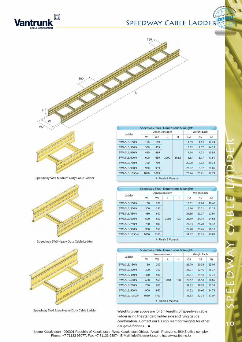
L
W2
W
H
300
150
LadderDimensions mm Weight Each
W W2 L H GA SS GX
SW6/SL3/150/# 150 200
3000 150
21.70 20.33 23.04
SW6/SL3/300/# 300 350 25.01 22.40 25.37
SW6/SL3/450/# 450 500 27.31 24.46 27.71
SW6/SL3/600/# 600 650 29.62 26.53 30.05
SW6/SL3/750/# 750 800 31.92 28.59 32.39
SW6/SL3/900/# 900 950 34.22 30.66 34.73
SW6/SL3/1050/# 1050 1100 36.53 32.72 37.07
# - Finish & Material
10
spe
ed
wa
y c
ab
le l
ad
de
r
Speedway Cable Ladder
Weights given above are for 3m lengths of Speedway cable ladder using the standard ladder side and rung gauge combination. Contact our Design Team for weights for other gauges & finishes.
Speedway SW6 - Dimensions & Weights
Speedway SW4 Medium Duty Cable Ladder
Speedway SW5 Heavy Duty Cable Ladder
Speedway SW6 Extra Heavy Duty Cable Ladder
LadderDimensions mm Weight Each
W W2 L H GA SS GX
SW5/SL3/150/# 150 200
3000 125
18.31 17.94 19.46
SW5/SL3/300/# 300 350 19.94 20.01 21.18
SW5/SL3/450/# 450 500 21.56 22.07 22.91
SW5/SL3/600/# 600 650 23.19 24.14 24.64
SW5/SL3/750/# 750 800 27.53 26.20 26.37
SW5/SL3/900/# 900 950 29.70 28.26 28.10
SW5/SL3/1050/# 1050 1100 31.87 30.33 29.83
# - Finish & Material
Speedway SW5 - Dimensions & Weights
LadderDimensions mm Weight Each
W W2 L H GA SS GX
SW4/SL3/150/# 150 189
3000 103.5
11.69 11.13 12.24
SW4/SL3/300/# 300 339 13.32 12.67 14.15
SW4/SL3/450/# 450 489 14.94 14.22 15.88
SW4/SL3/600/# 600 639 16.57 15.77 17.61
SW4/SL3/750/# 750 789 20.90 17.32 19.34
SW4/SL3/900/# 900 939 23.07 18.87 21.06
SW4/SL3/1050/# 1050 1089 25.24 20.41 22.79
# - Finish & Material
Speedway SW4 - Dimensions & Weights
ibemo Kazakhstan - 090301 Republic of Kazakhstan, West Kazakhstan Oblast, Aksai, Pramzone, BKKS office complex Phone: +7 71133 93077; Fax: +7 71133 93074; E-Mail: [email protected]; http://www.ibemo.kz
ibemoIND
USTR
IA
L & ELECTRICAL EQUIPMENT
spe
ed
wa
y c
ou
ple
rs
Speedway Couplers
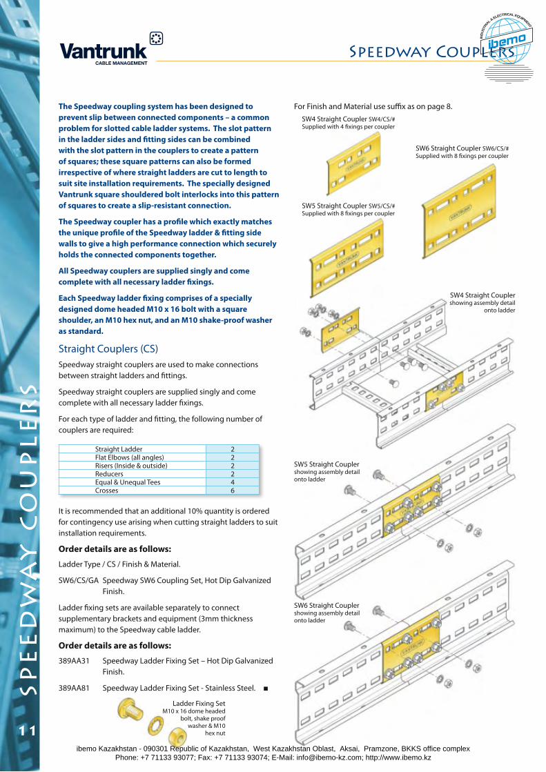
The Speedway coupling system has been designed to prevent slip between connected components – a common problem for slotted cable ladder systems. The slot pattern in the ladder sides and fitting sides can be combined with the slot pattern in the couplers to create a pattern of squares; these square patterns can also be formed irrespective of where straight ladders are cut to length to suit site installation requirements. The specially designed Vantrunk square shouldered bolt interlocks into this pattern of squares to create a slip-resistant connection.
The Speedway coupler has a profile which exactly matches the unique profile of the Speedway ladder & fitting side walls to give a high performance connection which securely holds the connected components together.
All Speedway couplers are supplied singly and come complete with all necessary ladder fixings.
Each Speedway ladder fixing comprises of a specially designed dome headed M10 x 16 bolt with a square shoulder, an M10 hex nut, and an M10 shake-proof washer as standard.
Straight Couplers (CS)Speedway straight couplers are used to make connections between straight ladders and fittings.
Speedway straight couplers are supplied singly and come complete with all necessary ladder fixings.
For each type of ladder and fitting, the following number of couplers are required:
It is recommended that an additional 10% quantity is ordered for contingency use arising when cutting straight ladders to suit installation requirements.
Order details are as follows:
Ladder Type / CS / Finish & Material.
SW6/CS/GA Speedway SW6 Coupling Set, Hot Dip Galvanized Finish.
Ladder fixing sets are available separately to connect supplementary brackets and equipment (3mm thickness maximum) to the Speedway cable ladder.
Order details are as follows:
389AA31 Speedway Ladder Fixing Set – Hot Dip Galvanized Finish.
389AA81 Speedway Ladder Fixing Set - Stainless Steel.
SW6 Straight Coupler showing assembly detail onto ladder
Ladder Fixing SetM10 x 16 dome headed
bolt, shake proof washer & M10
hex nut
SW5 Straight Coupler SW5/CS/# Supplied with 8 fixings per coupler
SW4 Straight Coupler SW4/CS/#Supplied with 4 fixings per coupler
SW6 Straight Coupler SW6/CS/#Supplied with 8 fixings per coupler
SW5 Straight Coupler showing assembly detail onto ladder
SW4 Straight Coupler showing assembly detail
onto ladder
Straight Ladder 2Flat Elbows (all angles) 2Risers (Inside & outside) 2Reducers 2Equal & Unequal Tees 4Crosses 6
11
For Finish and Material use suffix as on page 8.
ibemo Kazakhstan - 090301 Republic of Kazakhstan, West Kazakhstan Oblast, Aksai, Pramzone, BKKS office complex Phone: +7 71133 93077; Fax: +7 71133 93074; E-Mail: [email protected]; http://www.ibemo.kz
ibemoIND
USTR
IA
L & ELECTRICAL EQUIPMENT
spe
ed
wa
y c
ou
ple
rs
Speedway Couplers
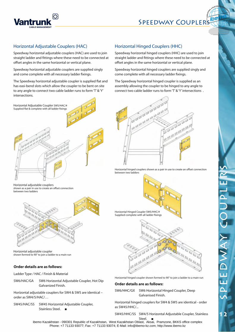
Horizontal Adjustable Couplers (HAC)Speedway horizontal adjustable couplers (HAC) are used to join straight ladder and fittings where these need to be connected at offset angles in the same horizontal or vertical plane.
Speedway horizontal adjustable couplers are supplied singly and come complete with all necessary ladder fixings.
The Speedway horizontal adjustable coupler is supplied flat and has easi-bend slots which allow the coupler to be bent on site to any angle to connect two cable ladder runs to form ‘T’ & ‘Y’ intersections.
Horizontal adjustable couplers shown as a pair in use to create an offset connection between two ladders
Order details are as follows:
Ladder Type / HAC / Finish & Material
SW6/HAC/GA SW6 Horizontal Adjustable Coupler, Hot Dip Galvanized Finish.
Horizontal adjustable couplers for SW4 & SW5 are identical – order as SW4/5/HAC/…
SW45/HAC/SS SW45 Horizontal Adjustable Coupler, Stainless Steel.
Horizontal Adjustable Coupler SW$/HAC/#Supplied flat & complete with all ladder fixings
12
Horizontal adjustable coupler shown formed to 90° to join a ladder to a main run
Horizontal Hinged Couplers (HHC)Speedway horizontal hinged couplers (HHC) are used to join straight ladder and fittings where these need to be connected at offset angles in the same horizontal or vertical plane.
Speedway horizontal hinged couplers are supplied singly and come complete with all necessary ladder fixings.
The Speedway horizontal hinged coupler is supplied as an assembly allowing the coupler to be hinged to any angle to connect two cable ladder runs to form ‘T’ & ‘Y’ intersections .
Horizontal hinged coupler shown formed to 90° to join a ladder to a main run
Horizontal Hinged Coupler SW$/HHC/# Supplied complete with all ladder fixings
Horizontal hinged couplers shown as a pair in use to create an offset connection between two ladders
Order details are as follows:
SW6/HHC/GX SW6 Horizontal Hinged Coupler, Deep Galvanised Finish.
Horizontal hinged couplers for SW4 & SW5 are identical - order as SW45/HHC/...
SW45/HHC/SS SW4/5 Horizontal Adjustable Coupler, Stainless Steel.
ibemo Kazakhstan - 090301 Republic of Kazakhstan, West Kazakhstan Oblast, Aksai, Pramzone, BKKS office complex Phone: +7 71133 93077; Fax: +7 71133 93074; E-Mail: [email protected]; http://www.ibemo.kz
ibemoIND
USTR
IA
L & ELECTRICAL EQUIPMENT
spe
ed
wa
y c
ou
ple
rs
Speedway Couplers
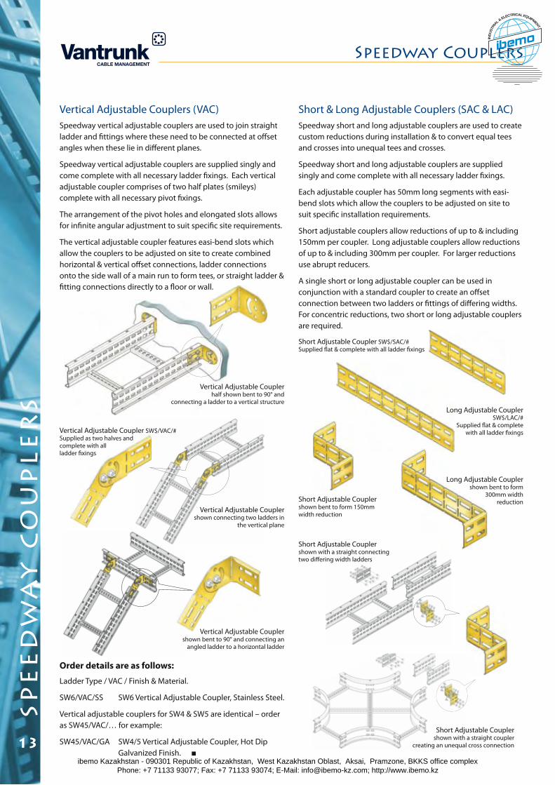
Short & Long Adjustable Couplers (SAC & LAC)Speedway short and long adjustable couplers are used to create custom reductions during installation & to convert equal tees and crosses into unequal tees and crosses.
Speedway short and long adjustable couplers are supplied singly and come complete with all necessary ladder fixings.
Each adjustable coupler has 50mm long segments with easi-bend slots which allow the couplers to be adjusted on site to suit specific installation requirements.
Short adjustable couplers allow reductions of up to & including 150mm per coupler. Long adjustable couplers allow reductions of up to & including 300mm per coupler. For larger reductions use abrupt reducers.
A single short or long adjustable coupler can be used in conjunction with a standard coupler to create an offset connection between two ladders or fittings of differing widths. For concentric reductions, two short or long adjustable couplers are required.
Long Adjustable Coupler SW$/LAC/#
Supplied flat & complete with all ladder fixings
Short Adjustable Coupler shown with a straight coupler
creating an unequal cross connection
Long Adjustable Coupler shown bent to form
300mm width reductionShort Adjustable Coupler
shown bent to form 150mm width reduction
13
Short Adjustable Coupler SW$/SAC/#Supplied flat & complete with all ladder fixings
Short Adjustable Coupler shown with a straight connecting two differing width ladders
Vertical Adjustable Couplers (VAC)Speedway vertical adjustable couplers are used to join straight ladder and fittings where these need to be connected at offset angles when these lie in different planes.
Speedway vertical adjustable couplers are supplied singly and come complete with all necessary ladder fixings. Each vertical adjustable coupler comprises of two half plates (smileys) complete with all necessary pivot fixings.
The arrangement of the pivot holes and elongated slots allows for infinite angular adjustment to suit specific site requirements.
The vertical adjustable coupler features easi-bend slots which allow the couplers to be adjusted on site to create combined horizontal & vertical offset connections, ladder connections onto the side wall of a main run to form tees, or straight ladder & fitting connections directly to a floor or wall.
Order details are as follows:
Ladder Type / VAC / Finish & Material.
SW6/VAC/SS SW6 Vertical Adjustable Coupler, Stainless Steel.
Vertical adjustable couplers for SW4 & SW5 are identical – order as SW45/VAC/… for example:
SW45/VAC/GA SW4/5 Vertical Adjustable Coupler, Hot Dip Galvanized Finish.
Vertical Adjustable Coupler shown bent to 90° and connecting an
angled ladder to a horizontal ladder
Vertical Adjustable Coupler half shown bent to 90° and
connecting a ladder to a vertical structure
Vertical Adjustable Coupler SW$/VAC/#Supplied as two halves and complete with all ladder fixings
Vertical Adjustable Coupler shown connecting two ladders in
the vertical plane
ibemo Kazakhstan - 090301 Republic of Kazakhstan, West Kazakhstan Oblast, Aksai, Pramzone, BKKS office complex Phone: +7 71133 93077; Fax: +7 71133 93074; E-Mail: [email protected]; http://www.ibemo.kz
ibemoIND
USTR
IA
L & ELECTRICAL EQUIPMENT
spe
ed
wa
y c
ou
ple
rs
Speedway Couplers
14
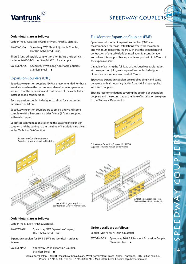
Expansion Couplers (EXP)Speedway expansion couplers (EXP) are recommended for those installations where the maximum and minimum temperatures are such that the expansion and contraction of the cable ladder installation is a consideration.
Each expansion coupler is designed to allow for a maximum movement of 28mm.
Speedway expansion couplers are supplied singly and come complete with all necessary ladder fixings (8 fixings supplied with each coupler).
Specific recommendations covering the spacing of expansion couplers and the setting gap at the time of installation are given in the ‘Technical Data’ section.
Expansion Coupler SW$/EXP/#Supplied complete with all ladder fixings
Installation gap required – see ‘Technical Data’ for more details.
Order details are as follows:
Ladder Type / Adjustable Coupler Type / Finish & Material.
SW6/SAC/GA Speedway SW6 Short Adjustable Coupler, Hot Dip Galvanized Finish.
Short & long adjustable couplers for SW4 & SW5 are identical – order as SW45/SAC/… or SW45/LAC/… for example:
SW45/LAC/SS Speedway SW45 Long Adjustable Coupler, Stainless Steel.
Order details are as follows:
Ladder Type / EXP / Finish & Material.
SW6/EXP/GX Speedway SW6 Expansion Coupler, Deep Galvanized Finish.
Expansion couplers for SW4 & SW5 are identical – order as follows:
SW45/EXP/SS Speedway SW45 Expansion Coupler, Stainless Steel.
Full Moment Expansion Couplers (FME)Speedway full moment expansion couplers (FME) are recommended for those installations where the maximum and minimum temperatures are such that the expansion and contraction of the cable ladder installation is a consideration and where it is not possible to provide support within 600mm of the expansion joint.
Capable of carrying the full load of the Speedway cable ladder at the expansion joint, each expansion coupler is designed to allow for a maximum movement of 75mm.
Speedway expansion couplers are supplied singly and come complete with all necessary ladder fixings (8 fixings supplied with each coupler).
Specific recommendations covering the spacing of expansion couplers and the setting gap at the time of installation are given in the ‘Technical Data’ section.
Full Moment Expansion Coupler SW$/FME/# Supplied complete with all ladder fixings
Installation gap required - see ‘Technical Data’ for more details
Order details are as follows:
Ladder Type / FME / Finish & Material
SW6/FME/SS Speedway SW6 Full Moment Expansion Coupler, Stainless Steel.
ibemo Kazakhstan - 090301 Republic of Kazakhstan, West Kazakhstan Oblast, Aksai, Pramzone, BKKS office complex Phone: +7 71133 93077; Fax: +7 71133 93074; E-Mail: [email protected]; http://www.ibemo.kz
ibemoIND
USTR
IA
L & ELECTRICAL EQUIPMENT
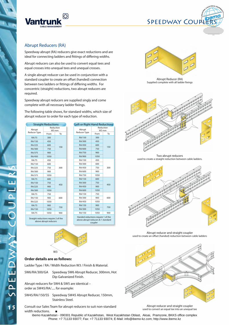
Abrupt Reducers (RA)Speedway abrupt (RA) reducers give exact reductions and are ideal for connecting ladders and fittings of differing widths.
Abrupt reducers can also be used to convert equal tees and equal crosses into unequal tees and unequal crosses.
A single abrupt reducer can be used in conjunction with a standard coupler to create an offset (handed) connection between two ladders or fittings of differing widths. For concentric (straight) reductions, two abrupt reducers are required.
Speedway abrupt reducers are supplied singly and come complete with all necessary ladder fixings.
The following table shows, for standard widths, which size of abrupt reducer to order for each type of reduction.
Order details are as follows:
Ladder Type / RA / Width Reduction W3 / Finish & Material.
SW6/RA/300/GA Speedway SW6 Abrupt Reducer, 300mm, Hot Dip Galvanized Finish.
Abrupt reducers for SW4 & SW5 are identical – order as SW45/RA/..... for example:
SW45/RA/150/SS Speedway SW45 Abrupt Reducer, 150mm, Stainless Steel.
Consult our Sales Team for abrupt reducers to suit non-standard width reductions.
Abrupt Reducer Type
Reduction W3 mm
From To
RA/75 300
150
RA/150 450
RA/225 600
RA/300 750
RA/375 900
RA/450 1050
RA/75 450
300
RA/150 600
RA/225 750
RA/300 900
RA/375 1050
RA/75 600
450RA/150 750
RA/225 900
RA/300 1050
RA/75 750
600RA/150 900
RA/225 1050
RA/75 900750
RA/150 1050
RA/75 1050 900
Straight reductions require 2 of the above abrupt reducers
Abrupt Reducer Type
Reduction W3 mm
From To
RA/150 300
150
RA/300 450
RA/450 600
RA/600 750
RA/750 900
RA/900 1050
RA/150 450
300
RA/300 600
RA/450 750
RA/600 900
RA/750 1050
RA/150 600
450RA/300 750
RA/450 900
RA/600 1050
RA/150 750
600RA/300 900
RA/450 1050
RA/150 900750
RA/300 1050
RA/150 1050 900
Handed reductions require 1 of the above abrupt reducers & 1 standard
coupler
Straight Reductions Left or Right Hand Reductions
W3
Two abrupt reducers used to create a straight reduction between cable ladders.
Abrupt Reducer (RA)Supplied complete with all ladder fixings
Abrupt reducer and straight coupler used to create an offset (handed) reduction between cable ladders
Abrupt reducer and straight coupler used to convert an equal tee into an unequal tee
Speedway Couplers
15
spe
ed
wa
y c
ou
ple
rs
ibemo Kazakhstan - 090301 Republic of Kazakhstan, West Kazakhstan Oblast, Aksai, Pramzone, BKKS office complex Phone: +7 71133 93077; Fax: +7 71133 93074; E-Mail: [email protected]; http://www.ibemo.kz
ibemoIND
USTR
IA
L & ELECTRICAL EQUIPMENT
spe
ed
wa
y l
on
g s
pa
n c
ab
le l
ad
de
r
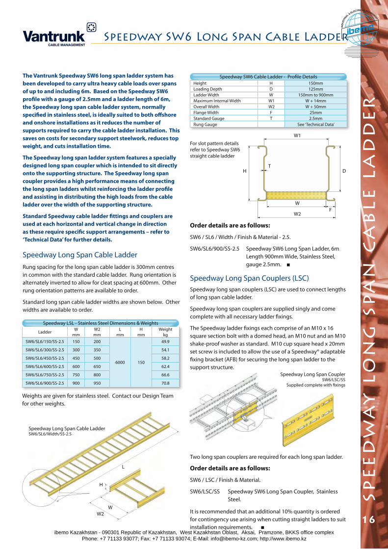
The Vantrunk Speedway SW6 long span ladder system has been developed to carry ultra heavy cable loads over spans of up to and including 6m. Based on the Speedway SW6 profile with a gauge of 2.5mm and a ladder length of 6m, the Speedway long span cable ladder system, normally specified in stainless steel, is ideally suited to both offshore and onshore installations as it reduces the number of supports required to carry the cable ladder installation. This saves on costs for secondary support steelwork, reduces top weight, and cuts installation time.
The Speedway long span ladder system features a specially designed long span coupler which is intended to sit directly onto the supporting structure. The Speedway long span coupler provides a high performance means of connecting the long span ladders whilst reinforcing the ladder profile and assisting in distributing the high loads from the cable ladder over the width of the supporting structure.
Standard Speedway cable ladder fittings and couplers are used at each horizontal and vertical change in direction as these require specific support arrangements – refer to ‘Technical Data’ for further details.
Ladder Wmm
W2mm
Lmm
Hmm
Weightkg
SW6/SL6/150/SS-2.5 150 200
6000 150
49.9
SW6/SL6/300/SS-2.5 300 350 54.1
SW6/SL6/450/SS-2.5 450 500 58.2
SW6/SL6/600/SS-2.5 600 650 62.4
SW6/SL6/750/SS-2.5 750 800 66.6
SW6/SL6/900/SS-2.5 900 950 70.8
Height H 150mmLoading Depth D 125mmLadder Width W 150mm to 900mmMaximum Internal Width W1 W + 14mmOverall Width W2 W + 50mmFlange Width F 25mmStandard Gauge T 2.5mmRung Gauge See ‘Technical Data’
Speedway LSL - Stainless Steel Dimensions & Weights
Weights are given for stainless steel. Contact our Design Team for other weights.
Order details are as follows:
SW6 / SL6 / Width / Finish & Material - 2.5.
SW6/SL6/900/SS-2.5 Speedway SW6 Long Span Ladder, 6m Length 900mm Wide, Stainless Steel, gauge 2.5mm.
Speedway Long Span Cable LadderRung spacing for the long span cable ladder is 300mm centres in common with the standard cable ladder. Rung orientation is alternately inverted to allow for cleat spacing at 600mm. Other rung orientation patterns are available to order.
Standard long span cable ladder widths are shown below. Other widths are available to order.
Speedway Long Span Cable LadderSW6/SL6/Width/SS-2.5
For slot pattern details refer to Speedway SW6 straight cable ladder
Speedway Long Span Couplers (LSC)Speedway long span couplers (LSC) are used to connect lengths of long span cable ladder.
Speedway long span couplers are supplied singly and come complete with all necessary ladder fixings.
The Speedway ladder fixings each comprise of an M10 x 16 square section bolt with a domed head, an M10 nut and an M10 shake-proof washer as standard. M10 cup square head x 20mm set screw is included to allow the use of a Speedway® adaptable fixing bracket (AFB) for securing the long span ladder to the support structure.
Two long span couplers are required for each long span ladder.
Order details are as follows:
SW6 / LSC / Finish & Material.
SW6/LSC/SS Speedway SW6 Long Span Coupler, Stainless Steel.
It is recommended that an additional 10% quantity is ordered for contingency use arising when cutting straight ladders to suit installation requirements.
Speedway Long Span CouplerSW6/LSC/SS
Supplied complete with fixings
W2
W
W1
TH D
L
H
WW2
F
Speedway SW6 Long Span Cable Ladder
16
Speedway SW6 Cable Ladder - Profile Details
ibemo Kazakhstan - 090301 Republic of Kazakhstan, West Kazakhstan Oblast, Aksai, Pramzone, BKKS office complex Phone: +7 71133 93077; Fax: +7 71133 93074; E-Mail: [email protected]; http://www.ibemo.kz
ibemoIND
USTR
IA
L & ELECTRICAL EQUIPMENT
Ladder W mm
W2 mm
L mm
H mm
Weight kg
SW4/XL3/150/GA 150 189
3000 103.5
16.19
SW4/XL3/300/GA 300 339 18.89
SW4/XL3/450/GA 450 489 21.93
SW4/XL3/600/GA 600 639 25.13
SW4/XL3/750/GA 750 789 31.27
SW4/XL3/900/GA 900 939 35.17
SW5/XL3/150/GA 150 200
3000 125
22.75
SW5/XL3/300/GA 300 350 25.45
SW5/XL3/450/GA 450 500 28.49
SW5/XL3/600/GA 600 650 31.69
SW5/XL3/750/GA 750 800 37.83
SW5/XL3/900/GA 900 950 41.73
SW6/XL3/150/GA 150 200
3000 150
25.81
SW6/XL3/300/GA 300 350 29.08
SW6/XL3/450/GA 450 500 32.69
SW6/XL3/600/GA 600 650 36.31
SW6/XL3/750/GA 750 800 40.32
SW6/XL3/900/GA 900 950 44.22
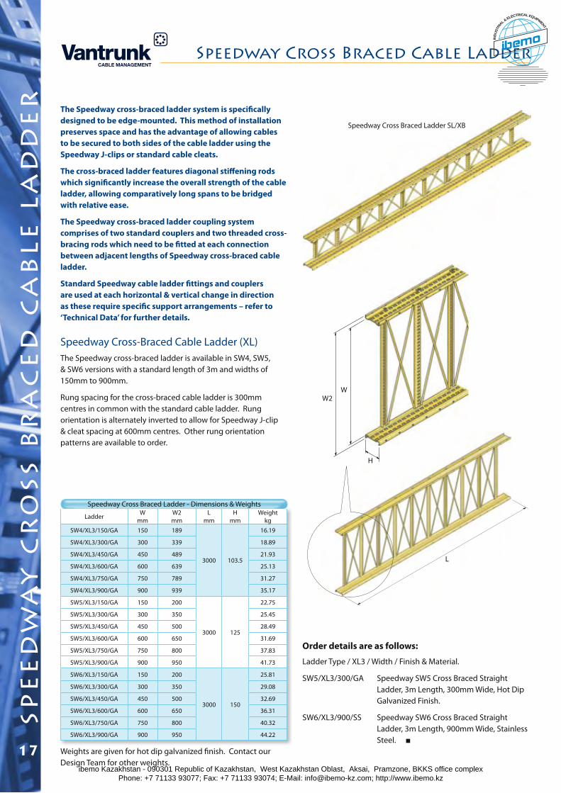
The Speedway cross-braced ladder system is specifically designed to be edge-mounted. This method of installation preserves space and has the advantage of allowing cables to be secured to both sides of the cable ladder using the Speedway J-clips or standard cable cleats.
The cross-braced ladder features diagonal stiffening rods which significantly increase the overall strength of the cable ladder, allowing comparatively long spans to be bridged with relative ease.
The Speedway cross-braced ladder coupling system comprises of two standard couplers and two threaded cross-bracing rods which need to be fitted at each connection between adjacent lengths of Speedway cross-braced cable ladder.
Standard Speedway cable ladder fittings and couplers are used at each horizontal & vertical change in direction as these require specific support arrangements – refer to ‘Technical Data’ for further details.
Speedway Cross-Braced Cable Ladder (XL)The Speedway cross-braced ladder is available in SW4, SW5, & SW6 versions with a standard length of 3m and widths of 150mm to 900mm.
Rung spacing for the cross-braced cable ladder is 300mm centres in common with the standard cable ladder. Rung orientation is alternately inverted to allow for Speedway J-clip & cleat spacing at 600mm centres. Other rung orientation patterns are available to order.
Order details are as follows:
Ladder Type / XL3 / Width / Finish & Material.
SW5/XL3/300/GA Speedway SW5 Cross Braced Straight Ladder, 3m Length, 300mm Wide, Hot Dip Galvanized Finish.
SW6/XL3/900/SS Speedway SW6 Cross Braced Straight Ladder, 3m Length, 900mm Wide, Stainless Steel.
Speedway Cross Braced Ladder - Dimensions & Weights
H
WW2
L
Speedway Cross Braced Ladder SL/XB
Weights are given for hot dip galvanized finish. Contact our Design Team for other weights.
17
spe
ed
wa
y c
ro
ss b
ra
ce
d c
ab
le l
ad
de
rSpeedway Cross Braced Cable Ladder
ibemo Kazakhstan - 090301 Republic of Kazakhstan, West Kazakhstan Oblast, Aksai, Pramzone, BKKS office complex Phone: +7 71133 93077; Fax: +7 71133 93074; E-Mail: [email protected]; http://www.ibemo.kz
ibemoIND
USTR
IA
L & ELECTRICAL EQUIPMENT
18
spe
ed
wa
y c
ro
ss b
ra
ce
d c
ab
le l
ad
de
r
Speedway Cross Braced Cable Ladder
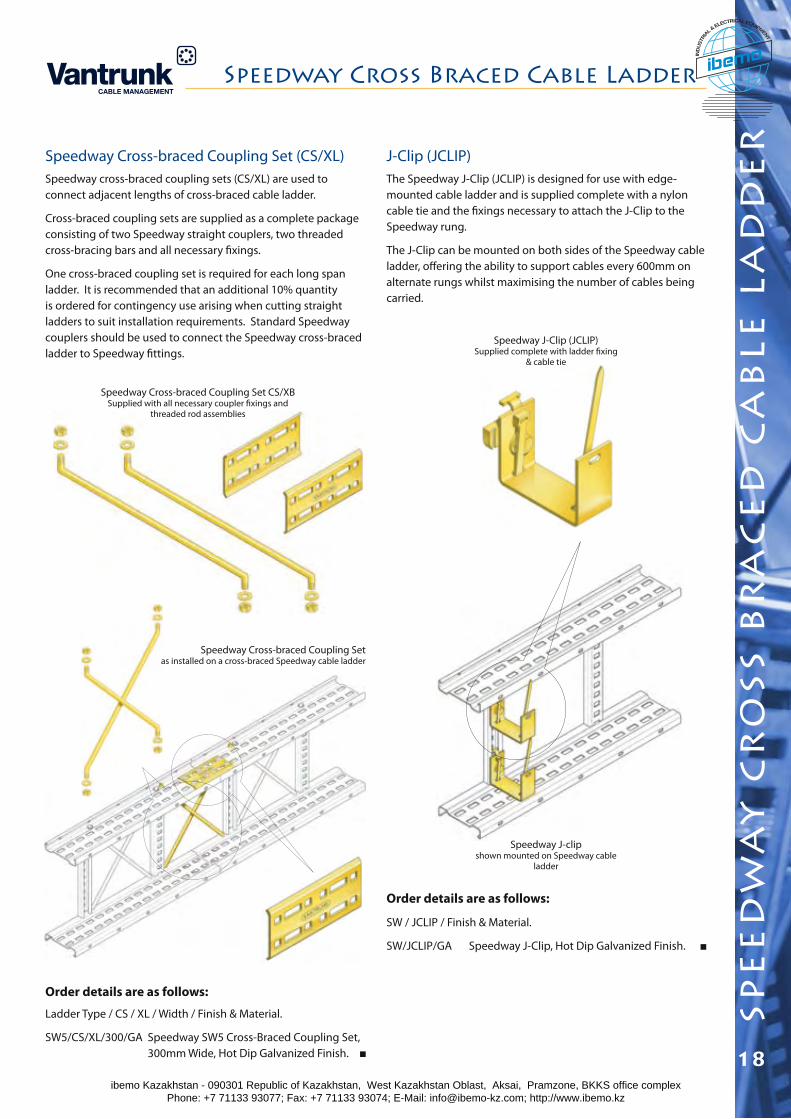
Speedway Cross-braced Coupling Set (CS/XL)Speedway cross-braced coupling sets (CS/XL) are used to connect adjacent lengths of cross-braced cable ladder.
Cross-braced coupling sets are supplied as a complete package consisting of two Speedway straight couplers, two threaded cross-bracing bars and all necessary fixings.
One cross-braced coupling set is required for each long span ladder. It is recommended that an additional 10% quantity is ordered for contingency use arising when cutting straight ladders to suit installation requirements. Standard Speedway couplers should be used to connect the Speedway cross-braced ladder to Speedway fittings.
Order details are as follows:
Ladder Type / CS / XL / Width / Finish & Material.
SW5/CS/XL/300/GA Speedway SW5 Cross-Braced Coupling Set, 300mm Wide, Hot Dip Galvanized Finish.
Speedway Cross-braced Coupling Set CS/XBSupplied with all necessary coupler fixings and
threaded rod assemblies
Speedway Cross-braced Coupling Set as installed on a cross-braced Speedway cable ladder
J-Clip (JCLIP)The Speedway J-Clip (JCLIP) is designed for use with edge-mounted cable ladder and is supplied complete with a nylon cable tie and the fixings necessary to attach the J-Clip to the Speedway rung.
The J-Clip can be mounted on both sides of the Speedway cable ladder, offering the ability to support cables every 600mm on alternate rungs whilst maximising the number of cables being carried.
Order details are as follows:
SW / JCLIP / Finish & Material.
SW/JCLIP/GA Speedway J-Clip, Hot Dip Galvanized Finish.
Speedway J-Clip (JCLIP)Supplied complete with ladder fixing
& cable tie
Speedway J-clip shown mounted on Speedway cable
ladder
ibemo Kazakhstan - 090301 Republic of Kazakhstan, West Kazakhstan Oblast, Aksai, Pramzone, BKKS office complex Phone: +7 71133 93077; Fax: +7 71133 93074; E-Mail: [email protected]; http://www.ibemo.kz
ibemoIND
USTR
IA
L & ELECTRICAL EQUIPMENT
spe
ed
wa
y f
lat
elb
ow
s
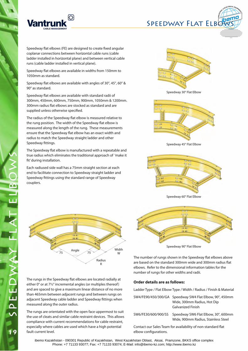
Speedway flat elbows (FE) are designed to create fixed angular coplanar connections between horizontal cable runs (cable ladder installed in horizontal plane) and between vertical cable runs (cable ladder installed in vertical plane).
Speedway flat elbows are available in widths from 150mm to 1050mm as standard.
Speedway flat elbows are available with angles of 30°, 45°, 60° & 90° as standard.
Speedway flat elbows are available with standard radii of 300mm, 450mm, 600mm, 750mm, 900mm, 1050mm & 1200mm. 300mm radius flat elbows are stocked as standard and are supplied unless otherwise specified.
The radius of the Speedway flat elbow is measured relative to the rung position. The width of the Speedway flat elbow is measured along the length of the rung. These measurements ensure that the Speedway flat elbow has an exact width and radius to match the Speedway straight ladder and other Speedway fittings.
The Speedway flat elbow is manufactured with a repeatable and true radius which eliminates the traditional approach of ‘make it fit’ during installation.
Each radiused side wall has a 75mm straight section at each end to facilitate connection to Speedway straight ladder and Speedway fittings using the standard range of Speedway couplers.
The rungs in the Speedway flat elbows are located radially at either 0° or at 7½° incremental angles (or multiples thereof ) and are spaced to give a maximum linear distance of no more than 465mm between adjacent rungs and between rungs on adjacent Speedway cable ladder and Speedway fittings when measured along the outer radius.
The rungs are orientated with the open face uppermost to suit the use of cleats and similar cable restraint devices. This allows compliance with current recommendations for cable restraint, especially where cables are used which have a high potential fault current level.
Order details are as follows:
Ladder Type / Flat Elbow Type / Width / Radius / Finish & Material
SW4/FE90/450/300/GA Speedway SW4 Flat Elbow, 90°, 450mm Wide, 300mm Radius, Hot Dip Galvanized Finish
SW6/FE30/600/900/SS Speedway SW6 Flat Elbow, 30°, 600mm Wide, 900mm Radius, Stainless Steel
Contact our Sales Team for availability of non-standard flat elbow configurations.
75Angle
RadiusR
WidthW75
Speedway 30° Flat Elbow
Speedway 45° Flat Elbow
Speedway 60° Flat Elbow
Speedway 90° Flat Elbow
The number of rungs shown in the Speedway flat elbows above are based on the standard 300mm wide and 300mm radius flat elbows. Refer to the dimensional information tables for the number of rungs for other widths and radii.
Speedway Flat Elbows
19ibemo Kazakhstan - 090301 Republic of Kazakhstan, West Kazakhstan Oblast, Aksai, Pramzone, BKKS office complex Phone: +7 71133 93077; Fax: +7 71133 93074; E-Mail: [email protected]; http://www.ibemo.kz
ibemoIND
USTR
IA
L & ELECTRICAL EQUIPMENT
spe
ed
wa
y f
lat
elb
ow
s
Speedway Flat Elbows
20
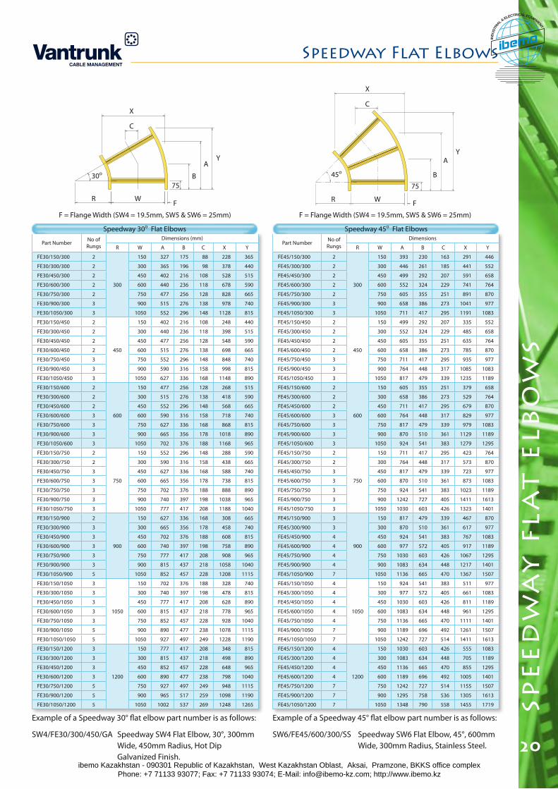
Part Number No of Rungs
Dimensions (mm)
R W A B C X Y
FE30/150/300 2
300
150 327 175 88 228 365
FE30/300/300 2 300 365 196 98 378 440
FE30/450/300 2 450 402 216 108 528 515
FE30/600/300 2 600 440 236 118 678 590
FE30/750/300 2 750 477 256 128 828 665
FE30/900/300 3 900 515 276 138 978 740
FE30/1050/300 3 1050 552 296 148 1128 815
FE30/150/450 2
450
150 402 216 108 248 440
FE30/300/450 2 300 440 236 118 398 515
FE30/450/450 2 450 477 256 128 548 590
FE30/600/450 2 600 515 276 138 698 665
FE30/750/450 3 750 552 296 148 848 740
FE30/900/450 3 900 590 316 158 998 815
FE30/1050/450 3 1050 627 336 168 1148 890
FE30/150/600 2
600
150 477 256 128 268 515
FE30/300/600 2 300 515 276 138 418 590
FE30/450/600 2 450 552 296 148 568 665
FE30/600/600 3 600 590 316 158 718 740
FE30/750/600 3 750 627 336 168 868 815
FE30/900/600 3 900 665 356 178 1018 890
FE30/1050/600 3 1050 702 376 188 1168 965
FE30/150/750 2
750
150 552 296 148 288 590
FE30/300/750 2 300 590 316 158 438 665
FE30/450/750 3 450 627 336 168 588 740
FE30/600/750 3 600 665 356 178 738 815
FE30/750/750 3 750 702 376 188 888 890
FE30/900/750 3 900 740 397 198 1038 965
FE30/1050/750 3 1050 777 417 208 1188 1040
FE30/150/900 2
900
150 627 336 168 308 665
FE30/300/900 3 300 665 356 178 458 740
FE30/450/900 3 450 702 376 188 608 815
FE30/600/900 3 600 740 397 198 758 890
FE30/750/900 3 750 777 417 208 908 965
FE30/900/900 3 900 815 437 218 1058 1040
FE30/1050/900 5 1050 852 457 228 1208 1115
FE30/150/1050 3
1050
150 702 376 188 328 740
FE30/300/1050 3 300 740 397 198 478 815
FE30/450/1050 3 450 777 417 208 628 890
FE30/600/1050 3 600 815 437 218 778 965
FE30/750/1050 3 750 852 457 228 928 1040
FE30/900/1050 5 900 890 477 238 1078 1115
FE30/1050/1050 5 1050 927 497 249 1228 1190
FE30/150/1200 3
1200
150 777 417 208 348 815
FE30/300/1200 3 300 815 437 218 498 890
FE30/450/1200 3 450 852 457 228 648 965
FE30/600/1200 3 600 890 477 238 798 1040
FE30/750/1200 5 750 927 497 249 948 1115
FE30/900/1200 5 900 965 517 259 1098 1190
FE30/1050/1200 5 1050 1002 537 269 1248 1265
Part Number No of Rungs
Dimensions
R W A B C X Y
FE45/150/300 2
300
150 393 230 163 291 446
FE45/300/300 2 300 446 261 185 441 552
FE45/450/300 2 450 499 292 207 591 658
FE45/600/300 2 600 552 324 229 741 764
FE45/750/300 2 750 605 355 251 891 870
FE45/900/300 3 900 658 386 273 1041 977
FE45/1050/300 3 1050 711 417 295 1191 1083
FE45/150/450 2
450
150 499 292 207 335 552
FE45/300/450 2 300 552 324 229 485 658
FE45/450/450 2 450 605 355 251 635 764
FE45/600/450 2 600 658 386 273 785 870
FE45/750/450 3 750 711 417 295 935 977
FE45/900/450 3 900 764 448 317 1085 1083
FE45/1050/450 3 1050 817 479 339 1235 1189
FE45/150/600 2
600
150 605 355 251 379 658
FE45/300/600 2 300 658 386 273 529 764
FE45/450/600 2 450 711 417 295 679 870
FE45/600/600 3 600 764 448 317 829 977
FE45/750/600 3 750 817 479 339 979 1083
FE45/900/600 3 900 870 510 361 1129 1189
FE45/1050/600 3 1050 924 541 383 1279 1295
FE45/150/750 2
750
150 711 417 295 423 764
FE45/300/750 2 300 764 448 317 573 870
FE45/450/750 3 450 817 479 339 723 977
FE45/600/750 3 600 870 510 361 873 1083
FE45/750/750 3 750 924 541 383 1023 1189
FE45/900/750 3 900 1242 727 405 1411 1613
FE45/1050/750 3 1050 1030 603 426 1323 1401
FE45/150/900 3
900
150 817 479 339 467 870
FE45/300/900 3 300 870 510 361 617 977
FE45/450/900 4 450 924 541 383 767 1083
FE45/600/900 4 600 977 572 405 917 1189
FE45/750/900 4 750 1030 603 426 1067 1295
FE45/900/900 4 900 1083 634 448 1217 1401
FE45/1050/900 7 1050 1136 665 470 1367 1507
FE45/150/1050 4
1050
150 924 541 383 511 977
FE45/300/1050 4 300 977 572 405 661 1083
FE45/450/1050 4 450 1030 603 426 811 1189
FE45/600/1050 4 600 1083 634 448 961 1295
FE45/750/1050 4 750 1136 665 470 1111 1401
FE45/900/1050 7 900 1189 696 492 1261 1507
FE45/1050/1050 7 1050 1242 727 514 1411 1613
FE45/150/1200 4
1200
150 1030 603 426 555 1083
FE45/300/1200 4 300 1083 634 448 705 1189
FE45/450/1200 4 450 1136 665 470 855 1295
FE45/600/1200 4 600 1189 696 492 1005 1401
FE45/750/1200 7 750 1242 727 514 1155 1507
FE45/900/1200 7 900 1295 758 536 1305 1613
FE45/1050/1200 7 1050 1348 790 558 1455 1719
Example of a Speedway 30° flat elbow part number is as follows:
SW4/FE30/300/450/GA Speedway SW4 Flat Elbow, 30°, 300mm Wide, 450mm Radius, Hot Dip Galvanized Finish.
F = Flange Width (SW4 = 19.5mm, SW5 & SW6 = 25mm)
Speedway 30o Flat Elbows Speedway 45o Flat Elbows
R W
30o
75B
AY
F
C
X
R W
45o
75
B
AY
F
C
X
F = Flange Width (SW4 = 19.5mm, SW5 & SW6 = 25mm)
Example of a Speedway 45° flat elbow part number is as follows:
SW6/FE45/600/300/SS Speedway SW6 Flat Elbow, 45°, 600mm Wide, 300mm Radius, Stainless Steel.
ibemo Kazakhstan - 090301 Republic of Kazakhstan, West Kazakhstan Oblast, Aksai, Pramzone, BKKS office complex Phone: +7 71133 93077; Fax: +7 71133 93074; E-Mail: [email protected]; http://www.ibemo.kz
ibemoIND
USTR
IA
L & ELECTRICAL EQUIPMENT
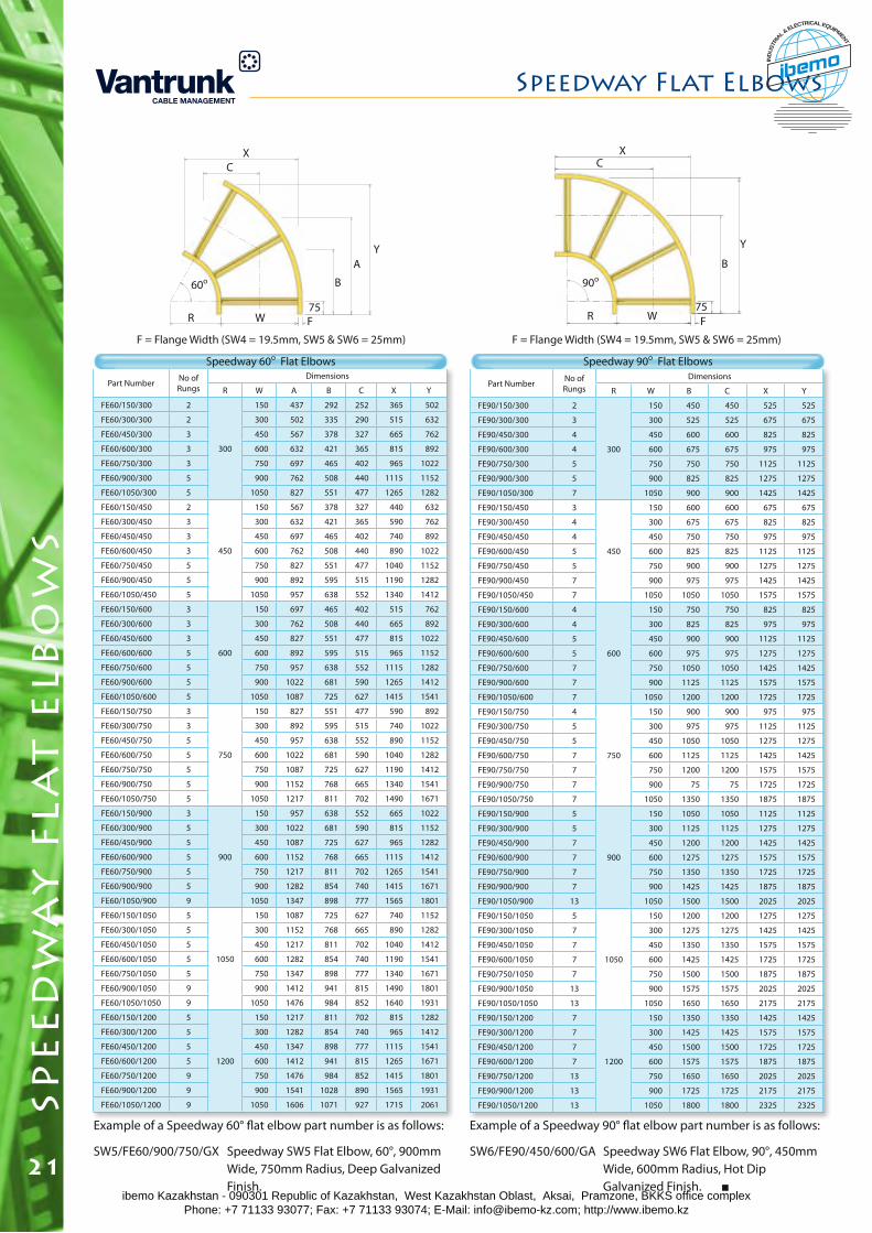
Part Number No of Rungs
Dimensions
R W A B C X Y
FE60/150/300 2
300
150 437 292 252 365 502
FE60/300/300 2 300 502 335 290 515 632
FE60/450/300 3 450 567 378 327 665 762
FE60/600/300 3 600 632 421 365 815 892
FE60/750/300 3 750 697 465 402 965 1022
FE60/900/300 5 900 762 508 440 1115 1152
FE60/1050/300 5 1050 827 551 477 1265 1282
FE60/150/450 2
450
150 567 378 327 440 632
FE60/300/450 3 300 632 421 365 590 762
FE60/450/450 3 450 697 465 402 740 892
FE60/600/450 3 600 762 508 440 890 1022
FE60/750/450 5 750 827 551 477 1040 1152
FE60/900/450 5 900 892 595 515 1190 1282
FE60/1050/450 5 1050 957 638 552 1340 1412
FE60/150/600 3
600
150 697 465 402 515 762
FE60/300/600 3 300 762 508 440 665 892
FE60/450/600 3 450 827 551 477 815 1022
FE60/600/600 5 600 892 595 515 965 1152
FE60/750/600 5 750 957 638 552 1115 1282
FE60/900/600 5 900 1022 681 590 1265 1412
FE60/1050/600 5 1050 1087 725 627 1415 1541
FE60/150/750 3
750
150 827 551 477 590 892
FE60/300/750 3 300 892 595 515 740 1022
FE60/450/750 5 450 957 638 552 890 1152
FE60/600/750 5 600 1022 681 590 1040 1282
FE60/750/750 5 750 1087 725 627 1190 1412
FE60/900/750 5 900 1152 768 665 1340 1541
FE60/1050/750 5 1050 1217 811 702 1490 1671
FE60/150/900 3
900
150 957 638 552 665 1022
FE60/300/900 5 300 1022 681 590 815 1152
FE60/450/900 5 450 1087 725 627 965 1282
FE60/600/900 5 600 1152 768 665 1115 1412
FE60/750/900 5 750 1217 811 702 1265 1541
FE60/900/900 5 900 1282 854 740 1415 1671
FE60/1050/900 9 1050 1347 898 777 1565 1801
FE60/150/1050 5
1050
150 1087 725 627 740 1152
FE60/300/1050 5 300 1152 768 665 890 1282
FE60/450/1050 5 450 1217 811 702 1040 1412
FE60/600/1050 5 600 1282 854 740 1190 1541
FE60/750/1050 5 750 1347 898 777 1340 1671
FE60/900/1050 9 900 1412 941 815 1490 1801
FE60/1050/1050 9 1050 1476 984 852 1640 1931
FE60/150/1200 5
1200
150 1217 811 702 815 1282
FE60/300/1200 5 300 1282 854 740 965 1412
FE60/450/1200 5 450 1347 898 777 1115 1541
FE60/600/1200 5 600 1412 941 815 1265 1671
FE60/750/1200 9 750 1476 984 852 1415 1801
FE60/900/1200 9 900 1541 1028 890 1565 1931
FE60/1050/1200 9 1050 1606 1071 927 1715 2061
F = Flange Width (SW4 = 19.5mm, SW5 & SW6 = 25mm)
Speedway 60o Flat Elbows
R W
60o
75
B
AY
F
CX
R W
90o
75
B
Y
F
C
F = Flange Width (SW4 = 19.5mm, SW5 & SW6 = 25mm)
X
Part Number No of Rungs
Dimensions
R W B C X Y
FE90/150/300 2
300
150 450 450 525 525
FE90/300/300 3 300 525 525 675 675
FE90/450/300 4 450 600 600 825 825
FE90/600/300 4 600 675 675 975 975
FE90/750/300 5 750 750 750 1125 1125
FE90/900/300 5 900 825 825 1275 1275
FE90/1050/300 7 1050 900 900 1425 1425
FE90/150/450 3
450
150 600 600 675 675
FE90/300/450 4 300 675 675 825 825
FE90/450/450 4 450 750 750 975 975
FE90/600/450 5 600 825 825 1125 1125
FE90/750/450 5 750 900 900 1275 1275
FE90/900/450 7 900 975 975 1425 1425
FE90/1050/450 7 1050 1050 1050 1575 1575
FE90/150/600 4
600
150 750 750 825 825
FE90/300/600 4 300 825 825 975 975
FE90/450/600 5 450 900 900 1125 1125
FE90/600/600 5 600 975 975 1275 1275
FE90/750/600 7 750 1050 1050 1425 1425
FE90/900/600 7 900 1125 1125 1575 1575
FE90/1050/600 7 1050 1200 1200 1725 1725
FE90/150/750 4
750
150 900 900 975 975
FE90/300/750 5 300 975 975 1125 1125
FE90/450/750 5 450 1050 1050 1275 1275
FE90/600/750 7 600 1125 1125 1425 1425
FE90/750/750 7 750 1200 1200 1575 1575
FE90/900/750 7 900 75 75 1725 1725
FE90/1050/750 7 1050 1350 1350 1875 1875
FE90/150/900 5
900
150 1050 1050 1125 1125
FE90/300/900 5 300 1125 1125 1275 1275
FE90/450/900 7 450 1200 1200 1425 1425
FE90/600/900 7 600 1275 1275 1575 1575
FE90/750/900 7 750 1350 1350 1725 1725
FE90/900/900 7 900 1425 1425 1875 1875
FE90/1050/900 13 1050 1500 1500 2025 2025
FE90/150/1050 5
1050
150 1200 1200 1275 1275
FE90/300/1050 7 300 1275 1275 1425 1425
FE90/450/1050 7 450 1350 1350 1575 1575
FE90/600/1050 7 600 1425 1425 1725 1725
FE90/750/1050 7 750 1500 1500 1875 1875
FE90/900/1050 13 900 1575 1575 2025 2025
FE90/1050/1050 13 1050 1650 1650 2175 2175
FE90/150/1200 7
1200
150 1350 1350 1425 1425
FE90/300/1200 7 300 1425 1425 1575 1575
FE90/450/1200 7 450 1500 1500 1725 1725
FE90/600/1200 7 600 1575 1575 1875 1875
FE90/750/1200 13 750 1650 1650 2025 2025
FE90/900/1200 13 900 1725 1725 2175 2175
FE90/1050/1200 13 1050 1800 1800 2325 2325
Example of a Speedway 60° flat elbow part number is as follows:
SW5/FE60/900/750/GX Speedway SW5 Flat Elbow, 60°, 900mm Wide, 750mm Radius, Deep Galvanized Finish.
Example of a Speedway 90° flat elbow part number is as follows:
SW6/FE90/450/600/GA Speedway SW6 Flat Elbow, 90°, 450mm Wide, 600mm Radius, Hot Dip Galvanized Finish.
Speedway 90o Flat Elbows
spe
ed
wa
y f
lat
elb
ow
sSpeedway Flat Elbows
21ibemo Kazakhstan - 090301 Republic of Kazakhstan, West Kazakhstan Oblast, Aksai, Pramzone, BKKS office complex Phone: +7 71133 93077; Fax: +7 71133 93074; E-Mail: [email protected]; http://www.ibemo.kz
ibemoIND
USTR
IA
L & ELECTRICAL EQUIPMENT
spe
ed
wa
y i
nsi
de
& o
ut
sid
e r
ise
rs
Speedway Inside & Outside Risers
22
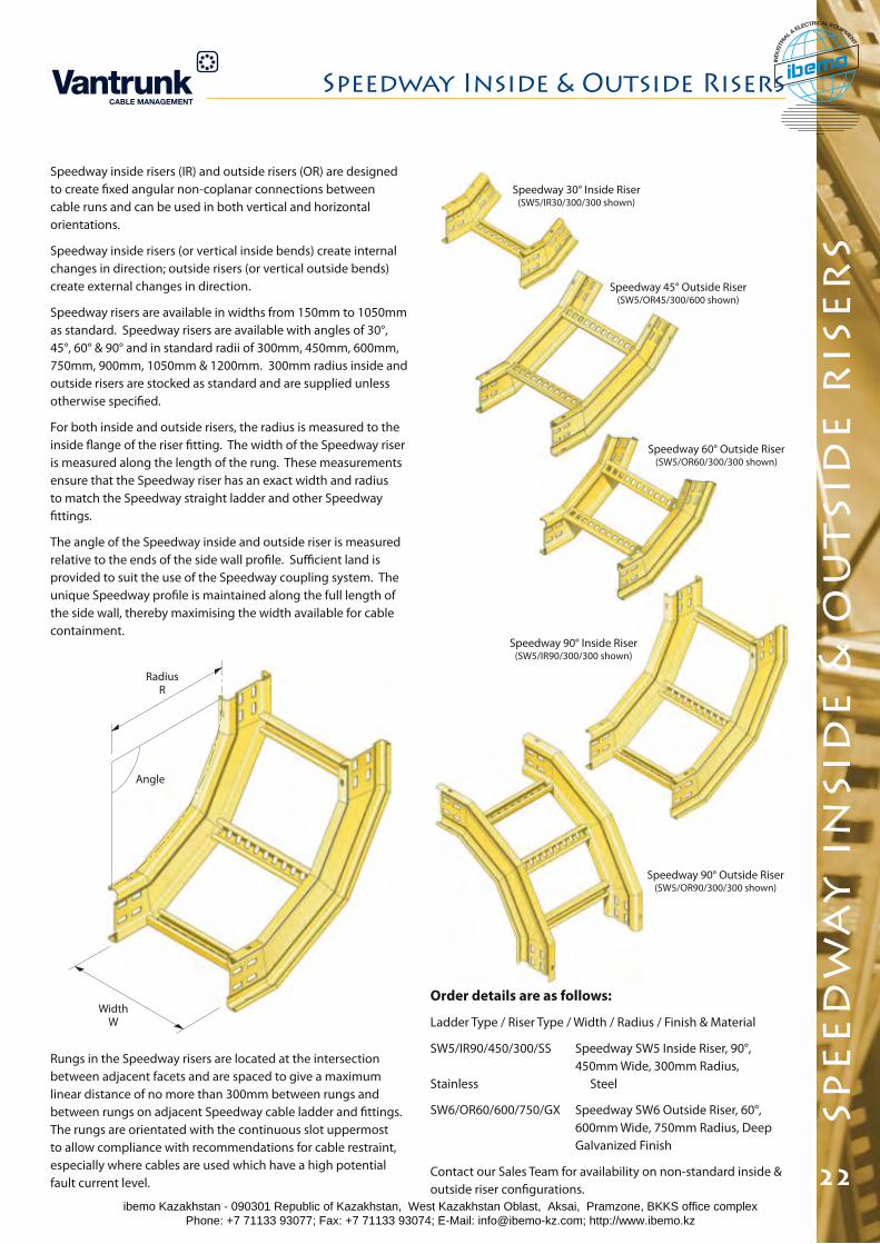
Speedway inside risers (IR) and outside risers (OR) are designed to create fixed angular non-coplanar connections between cable runs and can be used in both vertical and horizontal orientations.
Speedway inside risers (or vertical inside bends) create internal changes in direction; outside risers (or vertical outside bends) create external changes in direction.
Speedway risers are available in widths from 150mm to 1050mm as standard. Speedway risers are available with angles of 30°, 45°, 60° & 90° and in standard radii of 300mm, 450mm, 600mm, 750mm, 900mm, 1050mm & 1200mm. 300mm radius inside and outside risers are stocked as standard and are supplied unless otherwise specified.
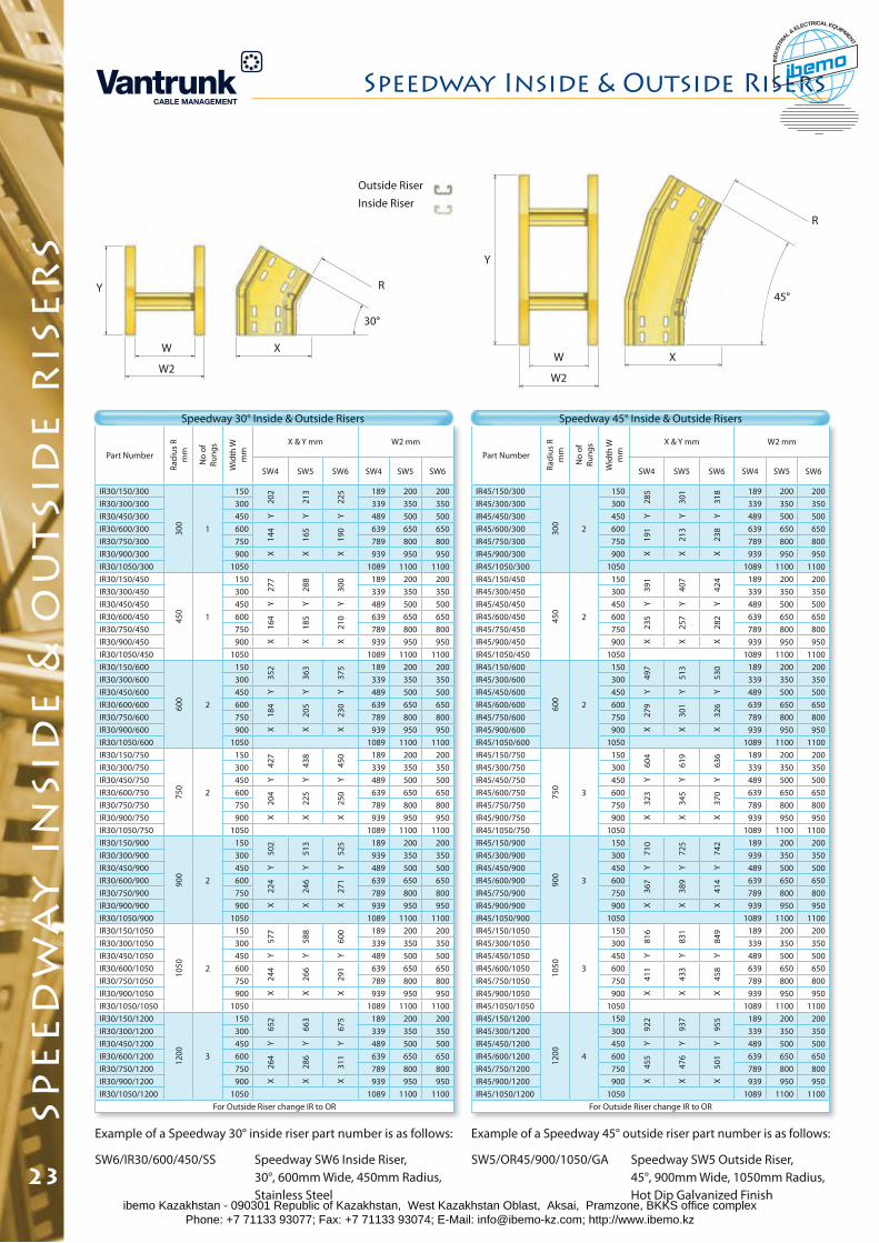
For both inside and outside risers, the radius is measured to the inside flange of the riser fitting. The width of the Speedway riser is measured along the length of the rung. These measurements ensure that the Speedway riser has an exact width and radius to match the Speedway straight ladder and other Speedway fittings.
The angle of the Speedway inside and outside riser is measured relative to the ends of the side wall profile. Sufficient land is provided to suit the use of the Speedway coupling system. The unique Speedway profile is maintained along the full length of the side wall, thereby maximising the width available for cable containment.
Order details are as follows:
Ladder Type / Riser Type / Width / Radius / Finish & Material
SW5/IR90/450/300/SS Speedway SW5 Inside Riser, 90°, 450mm Wide, 300mm Radius, Stainless Steel
SW6/OR60/600/750/GX Speedway SW6 Outside Riser, 60°, 600mm Wide, 750mm Radius, Deep Galvanized Finish
Contact our Sales Team for availability on non-standard inside & outside riser configurations.
Rungs in the Speedway risers are located at the intersection between adjacent facets and are spaced to give a maximum linear distance of no more than 300mm between rungs and between rungs on adjacent Speedway cable ladder and fittings. The rungs are orientated with the continuous slot uppermost to allow compliance with recommendations for cable restraint, especially where cables are used which have a high potential fault current level.
RadiusR
Angle
WidthW
Speedway 90° Inside Riser (SW5/IR90/300/300 shown)
Speedway 30° Inside Riser (SW5/IR30/300/300 shown)
Speedway 45° Outside Riser (SW5/OR45/300/600 shown)
Speedway 60° Outside Riser (SW5/OR60/300/300 shown)
Speedway 90° Outside Riser (SW5/OR90/300/300 shown)
ibemo Kazakhstan - 090301 Republic of Kazakhstan, West Kazakhstan Oblast, Aksai, Pramzone, BKKS office complex Phone: +7 71133 93077; Fax: +7 71133 93074; E-Mail: [email protected]; http://www.ibemo.kz
ibemoIND
USTR
IA
L & ELECTRICAL EQUIPMENT
Part Number
Radi
us R
m
m
No
of
Rung
s
Wid
th W
m
m
X & Y mm W2 mm
SW4 SW5 SW6 SW4 SW5 SW6
IR45/150/300
300
2
150
285
301
318 189 200 200
IR45/300/300 300 339 350 350IR45/450/300 450 Y Y Y 489 500 500IR45/600/300 600
191
213
238 639 650 650
IR45/750/300 750 789 800 800IR45/900/300 900 X X X 939 950 950IR45/1050/300 1050 1089 1100 1100IR45/150/450
450
2
150
391
407
424 189 200 200
IR45/300/450 300 339 350 350IR45/450/450 450 Y Y Y 489 500 500IR45/600/450 600
235
257
282 639 650 650
IR45/750/450 750 789 800 800IR45/900/450 900 X X X 939 950 950IR45/1050/450 1050 1089 1100 1100IR45/150/600
600
2
150
497
513
530 189 200 200
IR45/300/600 300 339 350 350IR45/450/600 450 Y Y Y 489 500 500IR45/600/600 600
279
301
326 639 650 650
IR45/750/600 750 789 800 800IR45/900/600 900 X X X 939 950 950IR45/1050/600 1050 1089 1100 1100IR45/150/750
750
3
150
604
619
636 189 200 200
IR45/300/750 300 339 350 350IR45/450/750 450 Y Y Y 489 500 500IR45/600/750 600
323
345
370 639 650 650
IR45/750/750 750 789 800 800IR45/900/750 900 X X X 939 950 950IR45/1050/750 1050 1089 1100 1100IR45/150/900
900
3
150
710
725
742 189 200 200
IR45/300/900 300 939 350 350IR45/450/900 450 Y Y Y 489 500 500IR45/600/900 600
367
389
414 639 650 650
IR45/750/900 750 789 800 800IR45/900/900 900 X X X 939 950 950IR45/1050/900 1050 1089 1100 1100IR45/150/1050
1050 3
150
816
831
849 189 200 200
IR45/300/1050 300 339 350 350IR45/450/1050 450 Y Y Y 489 500 500IR45/600/1050 600
411
433
458 639 650 650
IR45/750/1050 750 789 800 800IR45/900/1050 900 X X X 939 950 950IR45/1050/1050 1050 1089 1100 1100IR45/150/1200
1200 4
150
922
937
955 189 200 200
IR45/300/1200 300 339 350 350IR45/450/1200 450 Y Y Y 489 500 500IR45/600/1200 600
455
476
501 639 650 650
IR45/750/1200 750 789 800 800IR45/900/1200 900 X X X 939 950 950IR45/1050/1200 1050 1089 1100 1100
For Outside Riser change IR to OR
Part Number
Radi
us R
m
m
No
of
Rung
s
Wid
th W
m
m
X & Y mm W2 mm
SW4 SW5 SW6 SW4 SW5 SW6
IR30/150/300
300
1
150
202
213
225 189 200 200
IR30/300/300 300 339 350 350IR30/450/300 450 Y Y Y 489 500 500IR30/600/300 600
144
165
190 639 650 650
IR30/750/300 750 789 800 800IR30/900/300 900 X X X 939 950 950IR30/1050/300 1050 1089 1100 1100IR30/150/450
450
1
150
277
288
300 189 200 200
IR30/300/450 300 339 350 350IR30/450/450 450 Y Y Y 489 500 500IR30/600/450 600
164
185
210 639 650 650
IR30/750/450 750 789 800 800IR30/900/450 900 X X X 939 950 950IR30/1050/450 1050 1089 1100 1100IR30/150/600
600
2
150
352
363
375 189 200 200
IR30/300/600 300 339 350 350IR30/450/600 450 Y Y Y 489 500 500IR30/600/600 600
184
205
230 639 650 650
IR30/750/600 750 789 800 800IR30/900/600 900 X X X 939 950 950IR30/1050/600 1050 1089 1100 1100IR30/150/750
750
2
150
427
438
450 189 200 200
IR30/300/750 300 339 350 350IR30/450/750 450 Y Y Y 489 500 500IR30/600/750 600
204
225
250 639 650 650
IR30/750/750 750 789 800 800IR30/900/750 900 X X X 939 950 950IR30/1050/750 1050 1089 1100 1100IR30/150/900
900
2
150
502
513
525 189 200 200
IR30/300/900 300 939 350 350IR30/450/900 450 Y Y Y 489 500 500IR30/600/900 600
224
246
271 639 650 650
IR30/750/900 750 789 800 800IR30/900/900 900 X X X 939 950 950IR30/1050/900 1050 1089 1100 1100IR30/150/1050
1050 2
150
577
588
600 189 200 200
IR30/300/1050 300 339 350 350IR30/450/1050 450 Y Y Y 489 500 500IR30/600/1050 600
244
266
291 639 650 650
IR30/750/1050 750 789 800 800IR30/900/1050 900 X X X 939 950 950IR30/1050/1050 1050 1089 1100 1100IR30/150/1200
1200 3
150
652
663
675 189 200 200
IR30/300/1200 300 339 350 350IR30/450/1200 450 Y Y Y 489 500 500IR30/600/1200 600
264
286
311 639 650 650
IR30/750/1200 750 789 800 800IR30/900/1200 900 X X X 939 950 950IR30/1050/1200 1050 1089 1100 1100
For Outside Riser change IR to OR
Speedway 30° Inside & Outside Risers Speedway 45° Inside & Outside Risers
Example of a Speedway 45° outside riser part number is as follows:
SW5/OR45/900/1050/GA Speedway SW5 Outside Riser, 45°, 900mm Wide, 1050mm Radius, Hot Dip Galvanized Finish
Example of a Speedway 30° inside riser part number is as follows:
SW6/IR30/600/450/SS Speedway SW6 Inside Riser, 30°, 600mm Wide, 450mm Radius, Stainless Steel
Outside Riser
Inside Riser
Y
W
W2
X
30°
R
Y
W
W2
X
45°
R
spe
ed
wa
y i
nsi
de
& o
ut
sid
e r
ise
rs
Speedway Inside & Outside Risers
23ibemo Kazakhstan - 090301 Republic of Kazakhstan, West Kazakhstan Oblast, Aksai, Pramzone, BKKS office complex Phone: +7 71133 93077; Fax: +7 71133 93074; E-Mail: [email protected]; http://www.ibemo.kz
ibemoIND
USTR
IA
L & ELECTRICAL EQUIPMENT
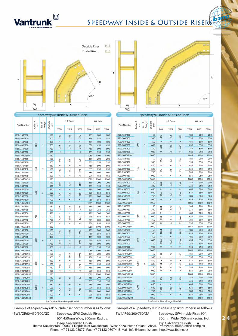
spe
ed
wa
y i
nsi
de
& o
ut
sid
e r
ise
rs
Speedway Inside & Outside Risers
24
Part Number
Radi
us R
m
m
No
of
Rung
s
Wid
th W
m
m
X & Y mm W2 mm
SW4 SW5 SW6 SW4 SW5 SW6
IR60/150/300
300
2
150
349
368
390 189 200 200
IR60/300/300 300 339 350 350IR60/450/300 450 Y Y Y 489 500 500IR60/600/300 600
254
275
300 639 650 650
IR60/750/300 750 789 800 800IR60/900/300 900 X X X 939 950 950IR60/1050/300 1050 1089 1100 1100IR60/150/450
450
2
150
479
498
520 189 200 200
IR60/300/450 300 339 350 350IR60/450/450 450 Y Y Y 489 500 500IR60/600/450 600
329
350
375 639 650 650
IR60/750/450 750 789 800 800IR60/900/450 900 X X X 939 950 950IR60/1050/450 1050 1089 1100 1100IR60/150/600
600
3
150
609
628
650 189 200 200
IR60/300/600 300 339 350 350IR60/450/600 450 Y Y Y 489 500 500IR60/600/600 600
404
425
450 639 650 650
IR60/750/600 750 789 800 800IR60/900/600 900 X X X 939 950 950IR60/1050/600 1050 1089 1100 1100IR60/150/750
750
3
150
739
758
779 189 200 200
IR60/300/750 300 339 350 350IR60/450/750 450 Y Y Y 489 500 500IR60/600/750 600
479
500
525 639 650 650
IR60/750/750 750 789 800 800IR60/900/750 900 X X X 939 950 950IR60/1050/750 1050 1089 1100 1100IR60/150/900
900
4
150
869
888
909 189 200 200
IR60/300/900 300 939 350 350IR60/450/900 450 Y Y Y 489 500 500IR60/600/900 600
554
575
600 639 650 650
IR60/750/900 750 789 800 800IR60/900/900 900 X X X 939 950 950IR60/1050/900 1050 1089 1100 1100IR60/150/1050
1050 4
150
999
1018
1093 189 200 200
IR60/300/1050 300 339 350 350IR60/450/1050 450 Y Y Y 489 500 500IR60/600/1050 600
629
650
675 639 650 650
IR60/750/1050 750 789 800 800IR60/900/1050 900 X X X 939 950 950IR60/1050/1050 1050 1089 1100 1100IR60/150/1200
1200 5
150
1129
1147
1169 189 200 200
IR60/300/1200 300 339 350 350IR60/450/1200 450 Y Y Y 489 500 500IR60/600/1200 600
704
725
750 639 650 650
IR60/750/1200 750 789 800 800IR60/900/1200 900 X X X 939 950 950IR60/1050/1200 1050 1089 1100 1100
For Outside Riser change IR to OR
Part Number
Radi
us R
m
m
No
of
Rung
s
Wid
th W
m
m
X & Y mm W2 mm
SW4 SW5 SW6 SW4 SW5 SW6
IR90/150/30030
0
3
150
404
425
450 189 200 200
IR90/300/300 300 339 350 350IR90/450/300 450 Y Y Y 489 500 500IR90/600/300 600
404
425
450 639 650 650
IR90/750/300 750 789 800 800IR90/900/300 900 X X X 939 950 950IR90/1050/300 1050 1089 1100 1100IR90/150/450
450
3
15055
4
575
600 189 200 200
IR90/300/450 300 339 350 350IR90/450/450 450 Y Y Y 489 500 500IR90/600/450 600
554
575
600 639 650 650
IR90/750/450 750 789 800 800IR90/900/450 900 X X X 939 950 950IR90/1050/450 1050 1089 1100 1100IR90/150/600
600
4
150
704
725
750 189 200 200
IR90/300/600 300 339 350 350IR90/450/600 450 Y Y Y 489 500 500IR90/600/600 600
704
725
750 639 650 650
IR90/750/600 750 789 800 800IR90/900/600 900 X X X 939 950 950IR90/1050/600 1050 1089 1100 1100IR90/150/750
750
5
150
854
875
900 189 200 200
IR90/300/750 300 339 350 350IR90/450/750 450 Y Y Y 489 500 500IR90/600/750 600
854
875
900 639 650 650
IR90/750/750 750 789 800 800IR90/900/750 900 X X X 939 950 950IR90/1050/750 1050 1089 1100 1100IR90/150/900
900
6
150
1004
1025
1050 189 200 200
IR90/300/900 300 939 350 350IR90/450/900 450 Y Y Y 489 500 500IR90/600/900 600
1004
1025
1050 639 650 650
IR90/750/900 750 789 800 800IR90/900/900 900 X X X 939 950 950IR90/1050/900 1050 1089 1100 1100IR90/150/1050
1050 6
150
1154
1175
1200 189 200 200
IR90/300/1050 300 339 350 350IR90/450/1050 450 Y Y Y 489 500 500IR90/600/1050 600
1154
1175
1200 639 650 650
IR90/750/1050 750 789 800 800IR90/900/1050 900 X X X 939 950 950IR90/1050/1050 1050 1089 1100 1100IR90/150/1200
1200 7
150
1304
1325
1350 189 200 200
IR90/300/1200 300 339 350 350IR90/450/1200 450 Y Y Y 489 500 500IR90/600/1200 600
1304
1325
1350 639 650 650
IR90/750/1200 750 789 800 800IR90/900/1200 900 X X X 939 950 950IR90/1050/1200 1050 1089 1100 1100
For Outside Riser change IR to OR
Speedway 60° Inside & Outside Risers Speedway 90° Inside & Outside Risers
Example of a Speedway 90° inside riser part number is as follows:
SW4/IR90/300/750/GA Speedway SW4 Inside Riser, 90°, 300mm Wide, 750mm Radius, Hot Dip Galvanized Finish.
Example of a Speedway 60° outside riser part number is as follows:
SW5/OR60/450/900/GX Speedway SW5 Outside Riser, 60°, 450mm Wide, 900mm Radius, Deep Galvanized Finish.
Outside Riser
Inside Riser
Y
WW2
X
60°
R
Y
WW2
X
90°
R
ibemo Kazakhstan - 090301 Republic of Kazakhstan, West Kazakhstan Oblast, Aksai, Pramzone, BKKS office complex Phone: +7 71133 93077; Fax: +7 71133 93074; E-Mail: [email protected]; http://www.ibemo.kz
ibemoIND
USTR
IA
L & ELECTRICAL EQUIPMENT
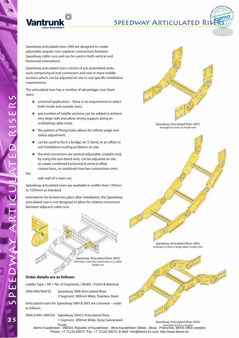
Speedway articulated risers (AR) are designed to create adjustable angular non-coplanar connections between Speedway cable runs and can be used in both vertical and horizontal orientations.
Speedway articulated risers consist of pre-assembled units, each comprising of end connectors and one or more middle sections which can be adjusted on site to suit specific installation requirements.
The articulated riser has a number of advantages over fixed risers:
universal application – there is no requirement to select both inside and outside risers.
any number of middle sections can be added to achieve very large radii and allow strong support along an undulating cable route.
the pattern of fixing holes allows for infinite angle and radius adjustment.
can be used to form a bridge, an ‘S’ bend, or an offset to suit installation routing problems on site.
the end connectors are vertical adjustable couplers and, by using the easi-bend slots, can be adjusted on site to create combined horizontal & vertical offset connections, or combined riser/tee connections onto the side wall of a main run.
Speedway articulated risers are available in widths from 150mm to 1050mm as standard.
Intended to be locked into place after installation, the Speedway articulated riser is not designed to allow for relative movement between adjacent cable runs.
Order details are as follows:
Ladder Type / AR + No. of Segments / Width / Finish & Material.
SW6/AR3/900/SS Speedway SW6 Articulated Riser, 3 Segment, 900mm Wide, Stainless Steel.
Articulated risers for Speedway SW4 & SW5 are common – order as follows:
SW4/5/AR1/300/GX Speedway SW4/5 Articulated Riser, 1 Segment, 300mm Wide, Deep Galvanized Finish.
Speedway Articulated Riser (AR1)arranged to form an inside riser
Speedway Articulated Riser (AR3)arranged to form a bridge
Speedway Articulated Riser (AR2)forming a riser/tee connection to a cable
ladder run
Speedway Articulated Riser (AR3)arranged to form a large radius inside riser
Speedway Articulated Riserssp
ee
dw
ay
ar
tic
ula
te
d r
ise
rs
25ibemo Kazakhstan - 090301 Republic of Kazakhstan, West Kazakhstan Oblast, Aksai, Pramzone, BKKS office complex Phone: +7 71133 93077; Fax: +7 71133 93074; E-Mail: [email protected]; http://www.ibemo.kz
ibemoIND
USTR
IA
L & ELECTRICAL EQUIPMENT
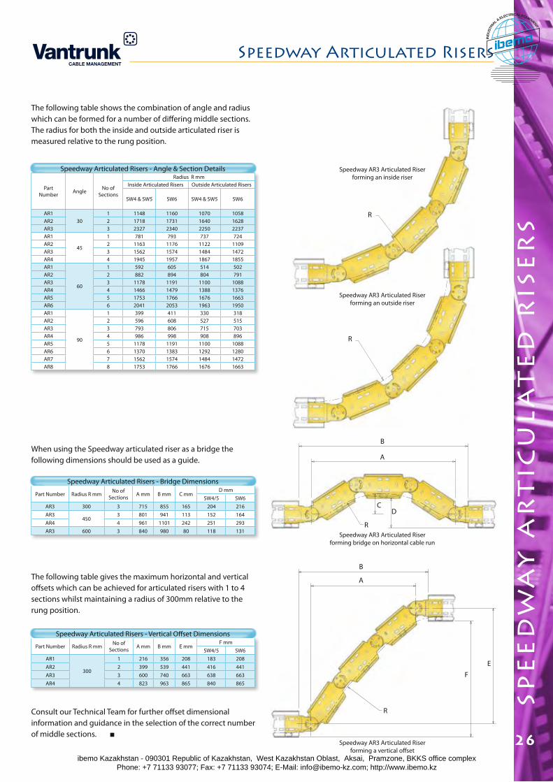
spe
ed
wa
y a
rt
icu
lat
ed
ris
er
s
Speedway Articulated Risers
26
The following table shows the combination of angle and radius which can be formed for a number of differing middle sections. The radius for both the inside and outside articulated riser is measured relative to the rung position.
Part Number Angle No of
Sections
Radius R mmInside Articulated Risers Outside Articulated Risers
SW4 & SW5 SW6 SW4 & SW5 SW6
AR130
1 1148 1160 1070 1058AR2 2 1718 1731 1640 1628AR3 3 2327 2340 2250 2237AR1
45
1 781 793 737 724AR2 2 1163 1176 1122 1109AR3 3 1562 1574 1484 1472AR4 4 1945 1957 1867 1855AR1
60
1 592 605 514 502AR2 2 882 894 804 791AR3 3 1178 1191 1100 1088AR4 4 1466 1479 1388 1376AR5 5 1753 1766 1676 1663AR6 6 2041 2053 1963 1950AR1
90
1 399 411 330 318AR2 2 596 608 527 515AR3 3 793 806 715 703AR4 4 986 998 908 896AR5 5 1178 1191 1100 1088AR6 6 1370 1383 1292 1280AR7 7 1562 1574 1484 1472AR8 8 1753 1766 1676 1663
Speedway AR3 Articulated Riser forming a vertical offset
Speedway Articulated Risers - Angle & Section Details
Part Number Radius R mm No of Sections A mm B mm C mm
D mmSW4/5 SW6
AR3 300 3 715 855 165 204 216AR3
4503 801 941 113 152 164
AR4 4 961 1101 242 251 293AR3 600 3 840 980 80 118 131
Speedway Articulated Risers - Bridge Dimensions
Part Number Radius R mm No of Sections A mm B mm E mm
F mmSW4/5 SW6
AR1
300
1 216 356 208 183 208AR2 2 399 539 441 416 441AR3 3 600 740 663 638 663AR4 4 823 963 865 840 865
Speedway Articulated Risers - Vertical Offset Dimensions
When using the Speedway articulated riser as a bridge the following dimensions should be used as a guide.
The following table gives the maximum horizontal and vertical offsets which can be achieved for articulated risers with 1 to 4 sections whilst maintaining a radius of 300mm relative to the rung position.
Consult our Technical Team for further offset dimensional information and guidance in the selection of the correct number of middle sections.
R
Speedway AR3 Articulated Riser forming bridge on horizontal cable run
Speedway AR3 Articulated Riser forming an outside riser
Speedway AR3 Articulated Riser forming an inside riser
R
B
A
CD
R
B
A
E
F
R
ibemo Kazakhstan - 090301 Republic of Kazakhstan, West Kazakhstan Oblast, Aksai, Pramzone, BKKS office complex Phone: +7 71133 93077; Fax: +7 71133 93074; E-Mail: [email protected]; http://www.ibemo.kz
ibemoIND
USTR
IA
L & ELECTRICAL EQUIPMENT
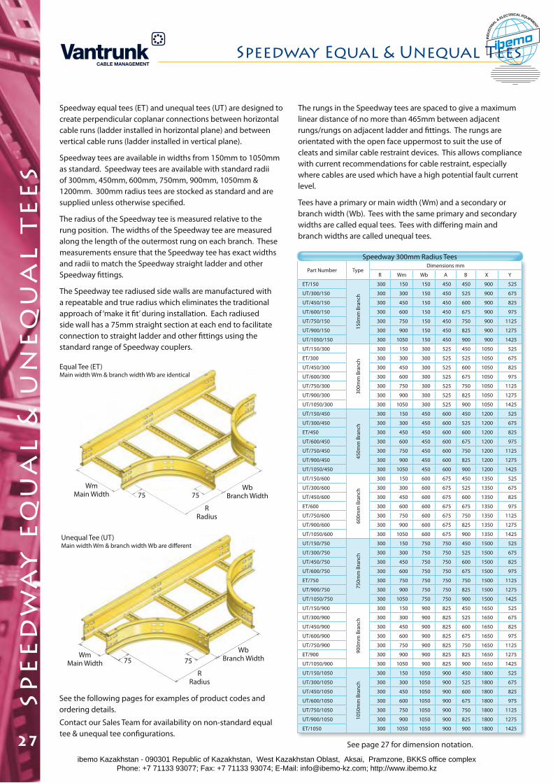
spe
ed
wa
y e
qu
al
& u
ne
qu
al
te
es
Speedway equal tees (ET) and unequal tees (UT) are designed to create perpendicular coplanar connections between horizontal cable runs (ladder installed in horizontal plane) and between vertical cable runs (ladder installed in vertical plane).
Speedway tees are available in widths from 150mm to 1050mm as standard. Speedway tees are available with standard radii of 300mm, 450mm, 600mm, 750mm, 900mm, 1050mm & 1200mm. 300mm radius tees are stocked as standard and are supplied unless otherwise specified.
The radius of the Speedway tee is measured relative to the rung position. The widths of the Speedway tee are measured along the length of the outermost rung on each branch. These measurements ensure that the Speedway tee has exact widths and radii to match the Speedway straight ladder and other Speedway fittings.
The Speedway tee radiused side walls are manufactured with a repeatable and true radius which eliminates the traditional approach of ‘make it fit’ during installation. Each radiused side wall has a 75mm straight section at each end to facilitate connection to straight ladder and other fittings using the standard range of Speedway couplers.
See the following pages for examples of product codes and ordering details.
Equal Tee (ET)Main width Wm & branch width Wb are identical
Unequal Tee (UT)Main width Wm & branch width Wb are different
7575
7575
Part Number TypeDimensions mm
R Wm Wb A B X Y
ET/150
150m
m B
ranc
h
300 150 150 450 450 900 525
UT/300/150 300 300 150 450 525 900 675
UT/450/150 300 450 150 450 600 900 825
UT/600/150 300 600 150 450 675 900 975
UT/750/150 300 750 150 450 750 900 1125
UT/900/150 300 900 150 450 825 900 1275
UT/1050/150 300 1050 150 450 900 900 1425
UT/150/300
300m
m B
ranc
h300 150 300 525 450 1050 525
ET/300 300 300 300 525 525 1050 675
UT/450/300 300 450 300 525 600 1050 825
UT/600/300 300 600 300 525 675 1050 975
UT/750/300 300 750 300 525 750 1050 1125
UT/900/300 300 900 300 525 825 1050 1275
UT/1050/300 300 1050 300 525 900 1050 1425
UT/150/450
450m
m B
ranc
h
300 150 450 600 450 1200 525
UT/300/450 300 300 450 600 525 1200 675
ET/450 300 450 450 600 600 1200 825
UT/600/450 300 600 450 600 675 1200 975
UT/750/450 300 750 450 600 750 1200 1125
UT/900/450 300 900 450 600 825 1200 1275
UT/1050/450 300 1050 450 600 900 1200 1425
UT/150/600
600m
m B
ranc
h
300 150 600 675 450 1350 525
UT/300/600 300 300 600 675 525 1350 675
UT/450/600 300 450 600 675 600 1350 825
ET/600 300 600 600 675 675 1350 975
UT/750/600 300 750 600 675 750 1350 1125
UT/900/600 300 900 600 675 825 1350 1275
UT/1050/600 300 1050 600 675 900 1350 1425
UT/150/750
750m
m B
ranc
h
300 150 750 750 450 1500 525
UT/300/750 300 300 750 750 525 1500 675
UT/450/750 300 450 750 750 600 1500 825
UT/600/750 300 600 750 750 675 1500 975
ET/750 300 750 750 750 750 1500 1125
UT/900/750 300 900 750 750 825 1500 1275
UT/1050/750 300 1050 750 750 900 1500 1425
UT/150/900
900m
m B
ranc
h
300 150 900 825 450 1650 525
UT/300/900 300 300 900 825 525 1650 675
UT/450/900 300 450 900 825 600 1650 825
UT/600/900 300 600 900 825 675 1650 975
UT/750/900 300 750 900 825 750 1650 1125
ET/900 300 900 900 825 825 1650 1275
UT/1050/900 300 1050 900 825 900 1650 1425
UT/150/1050
1050
mm
Bra
nch
300 150 1050 900 450 1800 525
UT/300/1050 300 300 1050 900 525 1800 675
UT/450/1050 300 450 1050 900 600 1800 825
UT/600/1050 300 600 1050 900 675 1800 975
UT/750/1050 300 750 1050 900 750 1800 1125
UT/900/1050 300 900 1050 900 825 1800 1275
ET/1050 300 1050 1050 900 900 1800 1425
The rungs in the Speedway tees are spaced to give a maximum linear distance of no more than 465mm between adjacent rungs/rungs on adjacent ladder and fittings. The rungs are orientated with the open face uppermost to suit the use of cleats and similar cable restraint devices. This allows compliance with current recommendations for cable restraint, especially where cables are used which have a high potential fault current level.
Tees have a primary or main width (Wm) and a secondary or branch width (Wb). Tees with the same primary and secondary widths are called equal tees. Tees with differing main and branch widths are called unequal tees.
Speedway 300mm Radius Tees
Contact our Sales Team for availability on non-standard equal tee & unequal tee configurations.
WbBranch Width
RRadius
WmMain Width
WbBranch Width
RRadius
WmMain Width
See page 27 for dimension notation.
Speedway Equal & Unequal Tees
27ibemo Kazakhstan - 090301 Republic of Kazakhstan, West Kazakhstan Oblast, Aksai, Pramzone, BKKS office complex Phone: +7 71133 93077; Fax: +7 71133 93074; E-Mail: [email protected]; http://www.ibemo.kz
ibemoIND
USTR
IA
L & ELECTRICAL EQUIPMENT
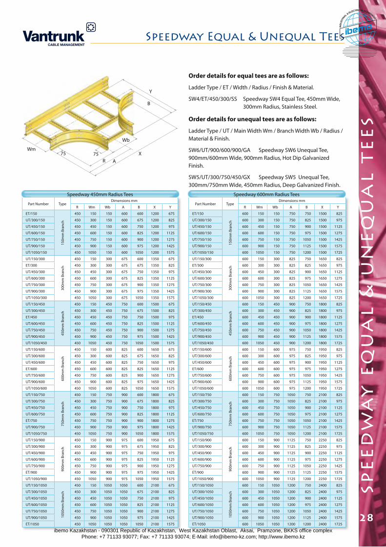
spe
ed
wa
y e
qu
al
& u
ne
qu
al
te
es
Speedway Equal & Unequal Tees
28
Order details for equal tees are as follows:
Ladder Type / ET / Width / Radius / Finish & Material.
SW4/ET/450/300/SS Speedway SW4 Equal Tee, 450mm Wide, 300mm Radius, Stainless Steel.
Order details for unequal tees are as follows:
Ladder Type / UT / Main Width Wm / Branch Width Wb / Radius / Material & Finish.
SW6/UT/900/600/900/GA Speedway SW6 Unequal Tee, 900mm/600mm Wide, 900mm Radius, Hot Dip Galvanized Finish.
SW5/UT/300/750/450/GX Speedway SW5 Unequal Tee, 300mm/750mm Wide, 450mm Radius, Deep Galvanized Finish.
Part Number TypeDimensions mm
R Wm Wb A B X Y
ET/150
150m
m B
ranc
h
450 150 150 600 600 1200 675
UT/300/150 450 300 150 600 675 1200 825
UT/450/150 450 450 150 600 750 1200 975
UT/600/150 450 600 150 600 825 1200 1125
UT/750/150 450 750 150 600 900 1200 1275
UT/900/150 450 900 150 600 975 1200 1425
UT/1050/150 450 1050 150 600 1050 1200 1575
UT/150/300
300m
m B
ranc
h
450 150 300 675 600 1350 675
ET/300 450 300 300 675 675 1350 825
UT/450/300 450 450 300 675 750 1350 975
UT/600/300 450 600 300 675 825 1350 1125
UT/750/300 450 750 300 675 900 1350 1275
UT/900/300 450 900 300 675 975 1350 1425
UT/1050/300 450 1050 300 675 1050 1350 1575
UT/150/450
450m
m B
ranc
h
450 150 450 750 600 1500 675
UT/300/450 450 300 450 750 675 1500 825
ET/450 450 450 450 750 750 1500 975
UT/600/450 450 600 450 750 825 1500 1125
UT/750/450 450 750 450 750 900 1500 1275
UT/900/450 450 900 450 750 975 1500 1425
UT/1050/450 450 1050 450 750 1050 1500 1575
UT/150/600
600m
m B
ranc
h
450 150 600 825 600 1650 675
UT/300/600 450 300 600 825 675 1650 825
UT/450/600 450 450 600 825 750 1650 975
ET/600 450 600 600 825 825 1650 1125
UT/750/600 450 750 600 825 900 1650 1275
UT/900/600 450 900 600 825 975 1650 1425
UT/1050/600 450 1050 600 825 1050 1650 1575
UT/150/750
750m
m B
ranc
h
450 150 750 900 600 1800 675
UT/300/750 450 300 750 900 675 1800 825
UT/450/750 450 450 750 900 750 1800 975
UT/600/750 450 600 750 900 825 1800 1125
ET/750 450 750 750 900 900 1800 1275
UT/900/750 450 900 750 900 975 1800 1425
UT/1050/750 450 1050 750 900 1050 1800 1575
UT/150/900
900m
m B
ranc
h
450 150 900 975 600 1950 675
UT/300/900 450 300 900 975 675 1950 825
UT/450/900 450 450 900 975 750 1950 975
UT/600/900 450 600 900 975 825 1950 1125
UT/750/900 450 750 900 975 900 1950 1275
ET/900 450 900 900 975 975 1950 1425
UT/1050/900 450 1050 900 975 1050 1950 1575
UT/150/1050
1050
mm
Bra
nch
450 150 1050 1050 600 2100 675
UT/300/1050 450 300 1050 1050 675 2100 825
UT/450/1050 450 450 1050 1050 750 2100 975
UT/600/1050 450 600 1050 1050 825 2100 1125
UT/750/1050 450 750 1050 1050 900 2100 1275
UT/900/1050 450 900 1050 1050 975 2100 1425
ET/1050 450 1050 1050 1050 1050 2100 1575
Part Number TypeDimensions mm
R Wm Wb A B X Y
ET/150
150m
m B
ranc
h
600 150 150 750 750 1500 825
UT/300/150 600 300 150 750 825 1500 975
UT/450/150 600 450 150 750 900 1500 1125
UT/600/150 600 600 150 750 975 1500 1275
UT/750/150 600 750 150 750 1050 1500 1425
UT/900/150 600 900 150 750 1125 1500 1575
UT/1050/150 600 1050 150 750 1200 1500 1725
UT/150/300
300m
m B
ranc
h
600 150 300 825 750 1650 825
ET/300 600 300 300 825 825 1650 975
UT/450/300 600 450 300 825 900 1650 1125
UT/600/300 600 600 300 825 975 1650 1275
UT/750/300 600 750 300 825 1050 1650 1425
UT/900/300 600 900 300 825 1125 1650 1575
UT/1050/300 600 1050 300 825 1200 1650 1725
UT/150/450
450m
m B
ranc
h
600 150 450 900 750 1800 825
UT/300/450 600 300 450 900 825 1800 975
ET/450 600 450 450 900 900 1800 1125
UT/600/450 600 600 450 900 975 1800 1275
UT/750/450 600 750 450 900 1050 1800 1425
UT/900/450 600 900 450 900 1125 1800 1575
UT/1050/450 600 1050 450 900 1200 1800 1725
UT/150/600
600m
m B
ranc
h
600 150 600 975 750 1950 825
UT/300/600 600 300 600 975 825 1950 975
UT/450/600 600 450 600 975 900 1950 1125
ET/600 600 600 600 975 975 1950 1275
UT/750/600 600 750 600 975 1050 1950 1425
UT/900/600 600 900 600 975 1125 1950 1575
UT/1050/600 600 1050 600 975 1200 1950 1725
UT/150/750
750m
m B
ranc
h
600 150 750 1050 750 2100 825
UT/300/750 600 300 750 1050 825 2100 975
UT/450/750 600 450 750 1050 900 2100 1125
UT/600/750 600 600 750 1050 975 2100 1275
ET/750 600 750 750 1050 1050 2100 1425
UT/900/750 600 900 750 1050 1125 2100 1575
UT/1050/750 600 1050 750 1050 1200 2100 1725
UT/150/900
900m
m B
ranc
h
600 150 900 1125 750 2250 825
UT/300/900 600 300 900 1125 825 2250 975
UT/450/900 600 450 900 1125 900 2250 1125
UT/600/900 600 600 900 1125 975 2250 1275
UT/750/900 600 750 900 1125 1050 2250 1425
ET/900 600 900 900 1125 1125 2250 1575
UT/1050/900 600 1050 900 1125 1200 2250 1725
UT/150/1050
1050
mm
Bra
nch
600 150 1050 1200 750 2400 825
UT/300/1050 600 300 1050 1200 825 2400 975
UT/450/1050 600 450 1050 1200 900 2400 1125
UT/600/1050 600 600 1050 1200 975 2400 1275
UT/750/1050 600 750 1050 1200 1050 2400 1425
UT/900/1050 600 900 1050 1200 1125 2400 1575
ET/1050 600 1050 1050 1200 1200 2400 1725
Speedway 450mm Radius Tees Speedway 600mm Radius Tees
Y
B
75R
Wb
AX
Wm75
ibemo Kazakhstan - 090301 Republic of Kazakhstan, West Kazakhstan Oblast, Aksai, Pramzone, BKKS office complex Phone: +7 71133 93077; Fax: +7 71133 93074; E-Mail: [email protected]; http://www.ibemo.kz
ibemoIND
USTR
IA
L & ELECTRICAL EQUIPMENT
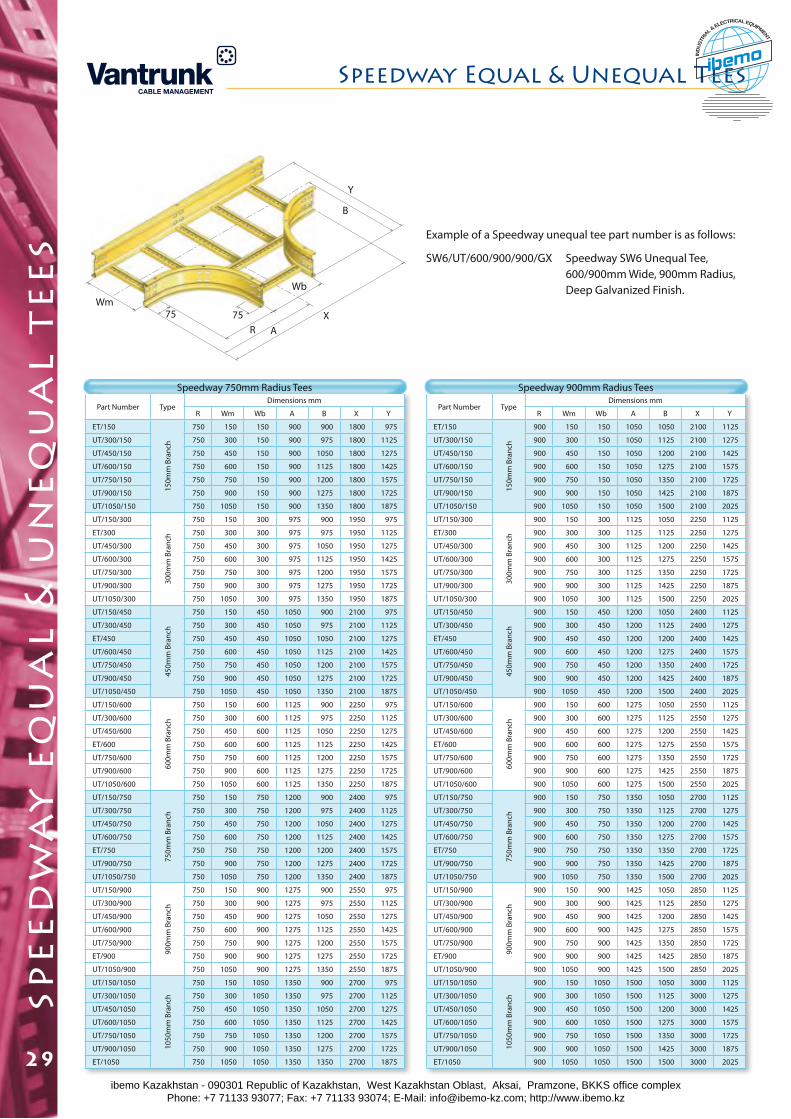
Y
B
75R
Wb
AX
Wm75
Example of a Speedway unequal tee part number is as follows:
SW6/UT/600/900/900/GX Speedway SW6 Unequal Tee, 600/900mm Wide, 900mm Radius, Deep Galvanized Finish.
Part Number TypeDimensions mm
R Wm Wb A B X Y
ET/150
150m
m B
ranc
h
750 150 150 900 900 1800 975
UT/300/150 750 300 150 900 975 1800 1125
UT/450/150 750 450 150 900 1050 1800 1275
UT/600/150 750 600 150 900 1125 1800 1425
UT/750/150 750 750 150 900 1200 1800 1575
UT/900/150 750 900 150 900 1275 1800 1725
UT/1050/150 750 1050 150 900 1350 1800 1875
UT/150/300
300m
m B
ranc
h
750 150 300 975 900 1950 975
ET/300 750 300 300 975 975 1950 1125
UT/450/300 750 450 300 975 1050 1950 1275
UT/600/300 750 600 300 975 1125 1950 1425
UT/750/300 750 750 300 975 1200 1950 1575
UT/900/300 750 900 300 975 1275 1950 1725
UT/1050/300 750 1050 300 975 1350 1950 1875
UT/150/450
450m
m B
ranc
h
750 150 450 1050 900 2100 975
UT/300/450 750 300 450 1050 975 2100 1125
ET/450 750 450 450 1050 1050 2100 1275
UT/600/450 750 600 450 1050 1125 2100 1425
UT/750/450 750 750 450 1050 1200 2100 1575
UT/900/450 750 900 450 1050 1275 2100 1725
UT/1050/450 750 1050 450 1050 1350 2100 1875
UT/150/600
600m
m B
ranc
h
750 150 600 1125 900 2250 975
UT/300/600 750 300 600 1125 975 2250 1125
UT/450/600 750 450 600 1125 1050 2250 1275
ET/600 750 600 600 1125 1125 2250 1425
UT/750/600 750 750 600 1125 1200 2250 1575
UT/900/600 750 900 600 1125 1275 2250 1725
UT/1050/600 750 1050 600 1125 1350 2250 1875
UT/150/750
750m
m B
ranc
h
750 150 750 1200 900 2400 975
UT/300/750 750 300 750 1200 975 2400 1125
UT/450/750 750 450 750 1200 1050 2400 1275
UT/600/750 750 600 750 1200 1125 2400 1425
ET/750 750 750 750 1200 1200 2400 1575
UT/900/750 750 900 750 1200 1275 2400 1725
UT/1050/750 750 1050 750 1200 1350 2400 1875
UT/150/900
900m
m B
ranc
h
750 150 900 1275 900 2550 975
UT/300/900 750 300 900 1275 975 2550 1125
UT/450/900 750 450 900 1275 1050 2550 1275
UT/600/900 750 600 900 1275 1125 2550 1425
UT/750/900 750 750 900 1275 1200 2550 1575
ET/900 750 900 900 1275 1275 2550 1725
UT/1050/900 750 1050 900 1275 1350 2550 1875
UT/150/1050
1050
mm
Bra
nch
750 150 1050 1350 900 2700 975
UT/300/1050 750 300 1050 1350 975 2700 1125
UT/450/1050 750 450 1050 1350 1050 2700 1275
UT/600/1050 750 600 1050 1350 1125 2700 1425
UT/750/1050 750 750 1050 1350 1200 2700 1575
UT/900/1050 750 900 1050 1350 1275 2700 1725
ET/1050 750 1050 1050 1350 1350 2700 1875
Part Number TypeDimensions mm
R Wm Wb A B X Y
ET/150
150m
m B
ranc
h
900 150 150 1050 1050 2100 1125
UT/300/150 900 300 150 1050 1125 2100 1275
UT/450/150 900 450 150 1050 1200 2100 1425
UT/600/150 900 600 150 1050 1275 2100 1575
UT/750/150 900 750 150 1050 1350 2100 1725
UT/900/150 900 900 150 1050 1425 2100 1875
UT/1050/150 900 1050 150 1050 1500 2100 2025
UT/150/300
300m
m B
ranc
h
900 150 300 1125 1050 2250 1125
ET/300 900 300 300 1125 1125 2250 1275
UT/450/300 900 450 300 1125 1200 2250 1425
UT/600/300 900 600 300 1125 1275 2250 1575
UT/750/300 900 750 300 1125 1350 2250 1725
UT/900/300 900 900 300 1125 1425 2250 1875
UT/1050/300 900 1050 300 1125 1500 2250 2025
UT/150/450
450m
m B
ranc
h
900 150 450 1200 1050 2400 1125
UT/300/450 900 300 450 1200 1125 2400 1275
ET/450 900 450 450 1200 1200 2400 1425
UT/600/450 900 600 450 1200 1275 2400 1575
UT/750/450 900 750 450 1200 1350 2400 1725
UT/900/450 900 900 450 1200 1425 2400 1875
UT/1050/450 900 1050 450 1200 1500 2400 2025
UT/150/600
600m
m B
ranc
h
900 150 600 1275 1050 2550 1125
UT/300/600 900 300 600 1275 1125 2550 1275
UT/450/600 900 450 600 1275 1200 2550 1425
ET/600 900 600 600 1275 1275 2550 1575
UT/750/600 900 750 600 1275 1350 2550 1725
UT/900/600 900 900 600 1275 1425 2550 1875
UT/1050/600 900 1050 600 1275 1500 2550 2025
UT/150/750
750m
m B
ranc
h
900 150 750 1350 1050 2700 1125
UT/300/750 900 300 750 1350 1125 2700 1275
UT/450/750 900 450 750 1350 1200 2700 1425
UT/600/750 900 600 750 1350 1275 2700 1575
ET/750 900 750 750 1350 1350 2700 1725
UT/900/750 900 900 750 1350 1425 2700 1875
UT/1050/750 900 1050 750 1350 1500 2700 2025
UT/150/900
900m
m B
ranc
h
900 150 900 1425 1050 2850 1125
UT/300/900 900 300 900 1425 1125 2850 1275
UT/450/900 900 450 900 1425 1200 2850 1425
UT/600/900 900 600 900 1425 1275 2850 1575
UT/750/900 900 750 900 1425 1350 2850 1725
ET/900 900 900 900 1425 1425 2850 1875
UT/1050/900 900 1050 900 1425 1500 2850 2025
UT/150/1050
1050
mm
Bra
nch
900 150 1050 1500 1050 3000 1125
UT/300/1050 900 300 1050 1500 1125 3000 1275
UT/450/1050 900 450 1050 1500 1200 3000 1425
UT/600/1050 900 600 1050 1500 1275 3000 1575
UT/750/1050 900 750 1050 1500 1350 3000 1725
UT/900/1050 900 900 1050 1500 1425 3000 1875
ET/1050 900 1050 1050 1500 1500 3000 2025
Speedway 750mm Radius Tees Speedway 900mm Radius Tees
spe
ed
wa
y e
qu
al
& u
ne
qu
al
te
es
Speedway Equal & Unequal Tees
29ibemo Kazakhstan - 090301 Republic of Kazakhstan, West Kazakhstan Oblast, Aksai, Pramzone, BKKS office complex Phone: +7 71133 93077; Fax: +7 71133 93074; E-Mail: [email protected]; http://www.ibemo.kz
ibemoIND
USTR
IA
L & ELECTRICAL EQUIPMENT
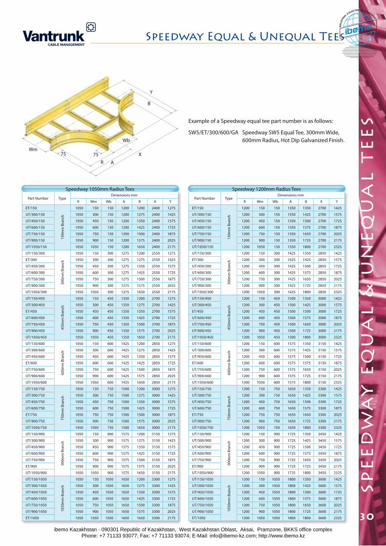
spe
ed
wa
y e
qu
al
& u
ne
qu
al
te
es
Speedway Equal & Unequal Tees
30
Y
B
75R
Wb
A
XWm
75
Part Number TypeDimensions mm
R Wm Wb A B X Y
ET/150
150m
m B
ranc
h
1050 150 150 1200 1200 2400 1275
UT/300/150 1050 300 150 1200 1275 2400 1425
UT/450/150 1050 450 150 1200 1350 2400 1575
UT/600/150 1050 600 150 1200 1425 2400 1725
UT/750/150 1050 750 150 1200 1500 2400 1875
UT/900/150 1050 900 150 1200 1575 2400 2025
UT/1050/150 1050 1050 150 1200 1650 2400 2175
UT/150/300
300m
m B
ranc
h
1050 150 300 1275 1200 2550 1275
ET/300 1050 300 300 1275 1275 2550 1425
UT/450/300 1050 450 300 1275 1350 2550 1575
UT/600/300 1050 600 300 1275 1425 2550 1725
UT/750/300 1050 750 300 1275 1500 2550 1875
UT/900/300 1050 900 300 1275 1575 2550 2025
UT/1050/300 1050 1050 300 1275 1650 2550 2175
UT/150/450
450m
m B
ranc
h
1050 150 450 1350 1200 2700 1275
UT/300/450 1050 300 450 1350 1275 2700 1425
ET/450 1050 450 450 1350 1350 2700 1575
UT/600/450 1050 600 450 1350 1425 2700 1725
UT/750/450 1050 750 450 1350 1500 2700 1875
UT/900/450 1050 900 450 1350 1575 2700 2025
UT/1050/450 1050 1050 450 1350 1650 2700 2175
UT/150/600
600m
m B
ranc
h
1050 150 600 1425 1200 2850 1275
UT/300/600 1050 300 600 1425 1275 2850 1425
UT/450/600 1050 450 600 1425 1350 2850 1575
ET/600 1050 600 600 1425 1425 2850 1725
UT/750/600 1050 750 600 1425 1500 2850 1875
UT/900/600 1050 900 600 1425 1575 2850 2025
UT/1050/600 1050 1050 600 1425 1650 2850 2175
UT/150/750
750m
m B
ranc
h
1050 150 750 1500 1200 3000 1275
UT/300/750 1050 300 750 1500 1275 3000 1425
UT/450/750 1050 450 750 1500 1350 3000 1575
UT/600/750 1050 600 750 1500 1425 3000 1725
ET/750 1050 750 750 1500 1500 3000 1875
UT/900/750 1050 900 750 1500 1575 3000 2025
UT/1050/750 1050 1050 750 1500 1650 3000 2175
UT/150/900
900m
m B
ranc
h
1050 150 900 1575 1200 3150 1275
UT/300/900 1050 300 900 1575 1275 3150 1425
UT/450/900 1050 450 900 1575 1350 3150 1575
UT/600/900 1050 600 900 1575 1425 3150 1725
UT/750/900 1050 750 900 1575 1500 3150 1875
ET/900 1050 900 900 1575 1575 3150 2025
UT/1050/900 1050 1050 900 1575 1650 3150 2175
UT/150/1050
1050
mm
Bra
nch
1050 150 1050 1650 1200 3300 1275
UT/300/1050 1050 300 1050 1650 1275 3300 1425
UT/450/1050 1050 450 1050 1650 1350 3300 1575
UT/600/1050 1050 600 1050 1650 1425 3300 1725
UT/750/1050 1050 750 1050 1650 1500 3300 1875
UT/900/1050 1050 900 1050 1650 1575 3300 2025
ET/1050 1050 1050 1050 1650 1650 3300 2175
Part Number TypeDimensions mm
R Wm Wb A B X Y
ET/150
150m
m B
ranc
h
1200 150 150 1350 1350 2700 1425
UT/300/150 1200 300 150 1350 1425 2700 1575
UT/450/150 1200 450 150 1350 1500 2700 1725
UT/600/150 1200 600 150 1350 1575 2700 1875
UT/750/150 1200 750 150 1350 1650 2700 2025
UT/900/150 1200 900 150 1350 1725 2700 2175
UT/1050/150 1200 1050 150 1350 1800 2700 2325
UT/150/300
300m
m B
ranc
h
1200 150 300 1425 1350 2850 1425
ET/300 1200 300 300 1425 1425 2850 1575
UT/450/300 1200 450 300 1425 1500 2850 1725
UT/600/300 1200 600 300 1425 1575 2850 1875
UT/750/300 1200 750 300 1425 1650 2850 2025
UT/900/300 1200 900 300 1425 1725 2850 2175
UT/1050/300 1200 1050 300 1425 1800 2850 2325
UT/150/450
450m
m B
ranc
h
1200 150 450 1500 1350 3000 1425
UT/300/450 1200 300 450 1500 1425 3000 1575
ET/450 1200 450 450 1500 1500 3000 1725
UT/600/450 1200 600 450 1500 1575 3000 1875
UT/750/450 1200 750 450 1500 1650 3000 2025
UT/900/450 1200 900 450 1500 1725 3000 2175
UT/1050/450 1200 1050 450 1500 1800 3000 2325
UT/150/600
600m
m B
ranc
h
1200 150 600 1575 1350 3150 1425
UT/300/600 1200 300 600 1575 1425 3150 1575
UT/450/600 1200 450 600 1575 1500 3150 1725
ET/600 1200 600 600 1575 1575 3150 1875
UT/750/600 1200 750 600 1575 1650 3150 2025
UT/900/600 1200 900 600 1575 1725 3150 2175
UT/1050/600 1200 1050 600 1575 1800 3150 2325
UT/150/750
750m
m B
ranc
h
1200 150 750 1650 1350 3300 1425
UT/300/750 1200 300 750 1650 1425 3300 1575
UT/450/750 1200 450 750 1650 1500 3300 1725
UT/600/750 1200 600 750 1650 1575 3300 1875
ET/750 1200 750 750 1650 1650 3300 2025
UT/900/750 1200 900 750 1650 1725 3300 2175
UT/1050/750 1200 1050 750 1650 1800 3300 2325
UT/150/900
900m
m B
ranc
h
1200 150 900 1725 1350 3450 1425
UT/300/900 1200 300 900 1725 1425 3450 1575
UT/450/900 1200 450 900 1725 1500 3450 1725
UT/600/900 1200 600 900 1725 1575 3450 1875
UT/750/900 1200 750 900 1725 1650 3450 2025
ET/900 1200 900 900 1725 1725 3450 2175
UT/1050/900 1200 1050 900 1725 1800 3450 2325
UT/150/1050
1050
mm
Bra
nch
1200 150 1050 1800 1350 3600 1425
UT/300/1050 1200 300 1050 1800 1425 3600 1575
UT/450/1050 1200 450 1050 1800 1500 3600 1725
UT/600/1050 1200 600 1050 1800 1575 3600 1875
UT/750/1050 1200 750 1050 1800 1650 3600 2025
UT/900/1050 1200 900 1050 1800 1725 3600 2175
ET/1050 1200 1050 1050 1800 1800 3600 2325
Example of a Speedway equal tee part number is as follows:
SW5/ET/300/600/GA Speedway SW5 Equal Tee, 300mm Wide, 600mm Radius, Hot Dip Galvanized Finish.
Speedway 1050mm Radius Tees Speedway 1200mm Radius Tees
ibemo Kazakhstan - 090301 Republic of Kazakhstan, West Kazakhstan Oblast, Aksai, Pramzone, BKKS office complex Phone: +7 71133 93077; Fax: +7 71133 93074; E-Mail: [email protected]; http://www.ibemo.kz
ibemoIND
USTR
IA
L & ELECTRICAL EQUIPMENT
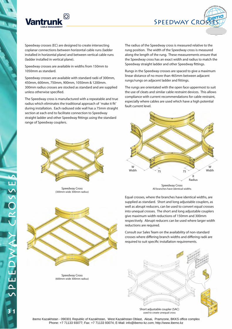
spe
ed
wa
y c
ro
sse
s
Speedway crosses (EC) are designed to create intersecting coplanar connections between horizontal cable runs (ladder installed in horizontal plane) and between vertical cable runs (ladder installed in vertical plane).
Speedway crosses are available in widths from 150mm to 1050mm as standard.
Speedway crosses are available with standard radii of 300mm, 450mm, 600mm, 750mm, 900mm, 1050mm & 1200mm. 300mm radius crosses are stocked as standard and are supplied unless otherwise specified.
The Speedway cross is manufactured with a repeatable and true radius which eliminates the traditional approach of ‘make it fit’ during installation. Each radiused side wall has a 75mm straight section at each end to facilitate connection to Speedway straight ladder and other Speedway fittings using the standard range of Speedway couplers.
The radius of the Speedway cross is measured relative to the rung position. The width of the Speedway cross is measured along the length of the rung. These measurements ensure that the Speedway cross has an exact width and radius to match the Speedway straight ladder and other Speedway fittings.
Rungs in the Speedway crosses are spaced to give a maximum linear distance of no more than 465mm between adjacent rungs/rungs on adjacent ladder and fittings.
The rungs are orientated with the open face uppermost to suit the use of cleats and similar cable restraint devices. This allows compliance with current recommendations for cable restraint, especially where cables are used which have a high potential fault current level.
Speedway Cross(300mm wide 300mm radius)
Short adjustable coupler (SAC) used to create unequal cross
Speedway CrossAll branches have identical widths
Speedway Cross(600mm wide 300mm radius)
Equal crosses, where the branches have identical widths, are supplied as standard. Short and long adjustable couplers, as well as abrupt reducers, can be used to convert equal crosses into unequal crosses. The short and long adjustable couplers give maximum width reductions of 150mm and 300mm respectively. Abrupt reducers can be used where larger width reductions are required.
Consult our Sales Team on the availability of non-standard crosses where differing branch widths and differing radii are required to suit specific installation requirements.
75 75
RRadius
WWidth
WWidth
Speedway Crosses
31ibemo Kazakhstan - 090301 Republic of Kazakhstan, West Kazakhstan Oblast, Aksai, Pramzone, BKKS office complex Phone: +7 71133 93077; Fax: +7 71133 93074; E-Mail: [email protected]; http://www.ibemo.kz
ibemoIND
USTR
IA
L & ELECTRICAL EQUIPMENT
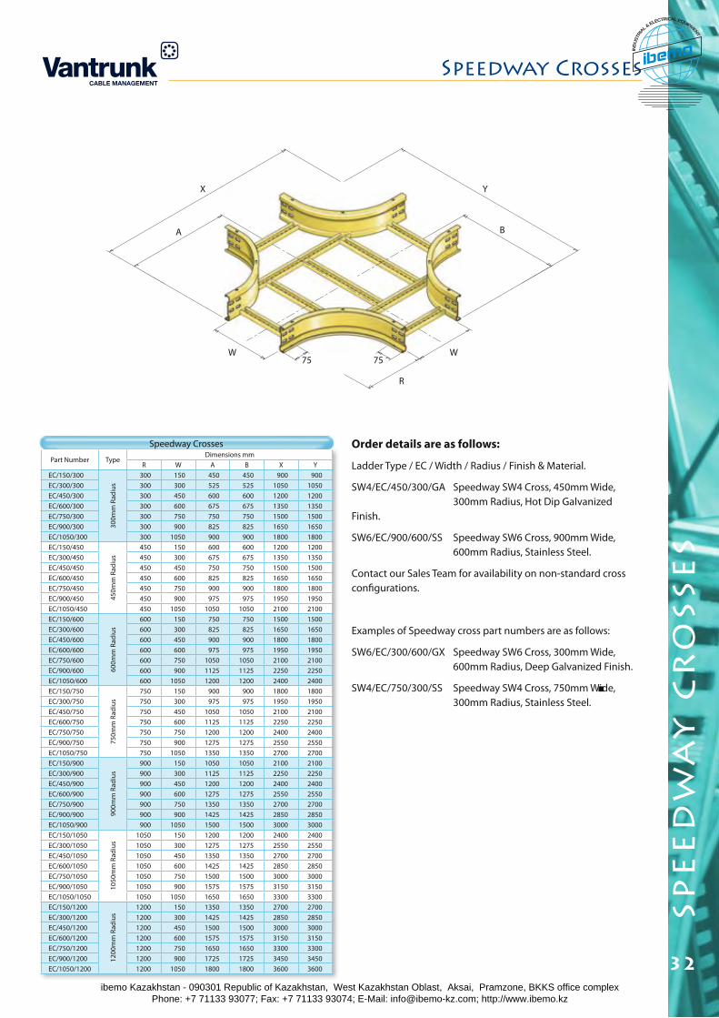
spe
ed
wa
y c
ro
sse
s
Speedway Crosses
32
Part Number TypeDimensions mm
R W A B X YEC/150/300
300m
m R
adiu
s
300 150 450 450 900 900EC/300/300 300 300 525 525 1050 1050EC/450/300 300 450 600 600 1200 1200EC/600/300 300 600 675 675 1350 1350EC/750/300 300 750 750 750 1500 1500EC/900/300 300 900 825 825 1650 1650EC/1050/300 300 1050 900 900 1800 1800EC/150/450
450m
m R
adiu
s
450 150 600 600 1200 1200EC/300/450 450 300 675 675 1350 1350EC/450/450 450 450 750 750 1500 1500EC/600/450 450 600 825 825 1650 1650EC/750/450 450 750 900 900 1800 1800EC/900/450 450 900 975 975 1950 1950EC/1050/450 450 1050 1050 1050 2100 2100EC/150/600
600m
m R
adiu
s
600 150 750 750 1500 1500EC/300/600 600 300 825 825 1650 1650EC/450/600 600 450 900 900 1800 1800EC/600/600 600 600 975 975 1950 1950EC/750/600 600 750 1050 1050 2100 2100EC/900/600 600 900 1125 1125 2250 2250EC/1050/600 600 1050 1200 1200 2400 2400EC/150/750
750m
m R
adiu
s
750 150 900 900 1800 1800EC/300/750 750 300 975 975 1950 1950EC/450/750 750 450 1050 1050 2100 2100EC/600/750 750 600 1125 1125 2250 2250EC/750/750 750 750 1200 1200 2400 2400EC/900/750 750 900 1275 1275 2550 2550EC/1050/750 750 1050 1350 1350 2700 2700EC/150/900
900m
m R
adiu
s
900 150 1050 1050 2100 2100EC/300/900 900 300 1125 1125 2250 2250EC/450/900 900 450 1200 1200 2400 2400EC/600/900 900 600 1275 1275 2550 2550EC/750/900 900 750 1350 1350 2700 2700EC/900/900 900 900 1425 1425 2850 2850EC/1050/900 900 1050 1500 1500 3000 3000EC/150/1050
1050
mm
Rad
ius
1050 150 1200 1200 2400 2400EC/300/1050 1050 300 1275 1275 2550 2550EC/450/1050 1050 450 1350 1350 2700 2700EC/600/1050 1050 600 1425 1425 2850 2850EC/750/1050 1050 750 1500 1500 3000 3000EC/900/1050 1050 900 1575 1575 3150 3150EC/1050/1050 1050 1050 1650 1650 3300 3300EC/150/1200
1200
mm
Rad
ius
1200 150 1350 1350 2700 2700EC/300/1200 1200 300 1425 1425 2850 2850EC/450/1200 1200 450 1500 1500 3000 3000EC/600/1200 1200 600 1575 1575 3150 3150EC/750/1200 1200 750 1650 1650 3300 3300EC/900/1200 1200 900 1725 1725 3450 3450EC/1050/1200 1200 1050 1800 1800 3600 3600
Speedway Crosses Order details are as follows:
Ladder Type / EC / Width / Radius / Finish & Material.
SW4/EC/450/300/GA Speedway SW4 Cross, 450mm Wide, 300mm Radius, Hot Dip Galvanized Finish.
SW6/EC/900/600/SS Speedway SW6 Cross, 900mm Wide, 600mm Radius, Stainless Steel.
Contact our Sales Team for availability on non-standard cross configurations.
Examples of Speedway cross part numbers are as follows:
SW6/EC/300/600/GX Speedway SW6 Cross, 300mm Wide, 600mm Radius, Deep Galvanized Finish.
SW4/EC/750/300/SS Speedway SW4 Cross, 750mm Wide, 300mm Radius, Stainless Steel.
75W
75W
R
B
YX
A
ibemo Kazakhstan - 090301 Republic of Kazakhstan, West Kazakhstan Oblast, Aksai, Pramzone, BKKS office complex Phone: +7 71133 93077; Fax: +7 71133 93074; E-Mail: [email protected]; http://www.ibemo.kz
ibemoIND
USTR
IA
L & ELECTRICAL EQUIPMENT
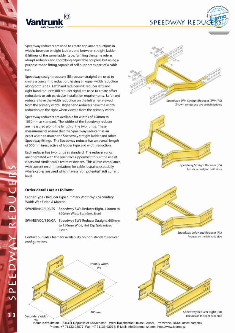
spe
ed
wa
y r
ed
uc
er
s
Speedway reducers are used to create coplanar reductions in widths between straight ladders and between straight ladder & fittings of the same ladder type, fulfilling the same role as abrupt reducers and short/long adjustable couplers but using a purpose-made fitting capable of self-support as part of a cable run.
Speedway straight reducers (RS reducer straight) are used to create a concentric reduction, having an equal width reduction along both sides. Left hand reducers (RL reducer left) and right hand reducers (RR reducer right) are used to create offset reductions to suit particular installation requirements. Left hand reducers have the width reduction on the left when viewed from the primary width. Right hand reducers have the width reduction on the right when viewed from the primary width.
Speedway reducers are available for widths of 150mm to 1050mm as standard. The widths of the Speedway reducer are measured along the length of the two rungs. These measurements ensure that the Speedway reducer has an exact width to match the Speedway straight ladder and other Speedway fittings. The Speedway reducer has an overall length of 500mm irrespective of ladder type and width reduction.
Each reducer has two rungs as standard. The reducer rungs are orientated with the open face uppermost to suit the use of cleats and similar cable restraint devices. This allows compliance with current recommendations for cable restraint, especially where cables are used which have a high potential fault current level.
Order details are as follows:
Ladder Type / Reducer Type / Primary Width Wp / Secondary Width Ws / Finish & Material
SW6/RR/450/300/SS Speedway SW6 Reducer Right, 450mm to 300mm Wide, Stainless Steel
SW4/RS/600/150/GA Speedway SW6 Reducer Straight, 600mm to 150mm Wide, Hot Dip Galvanized Finish
Contact our Sales Team for availability on non-standard reducer configurations.
Speedway Straight Reducer (RS)Reduces equally on both sides
Speedway Left Hand Reducer (RL)Reduces on the left hand side
Speedway Reducer Right (RR)Reduces on the right hand side
Speedway SW4 Straight Reducer (SW4/RS) Shown connecting two straight ladders
Secondary Width Ws
500mm
Primary Width Wp
Speedway Reducers
33ibemo Kazakhstan - 090301 Republic of Kazakhstan, West Kazakhstan Oblast, Aksai, Pramzone, BKKS office complex Phone: +7 71133 93077; Fax: +7 71133 93074; E-Mail: [email protected]; http://www.ibemo.kz
ibemoIND
USTR
IA
L & ELECTRICAL EQUIPMENT
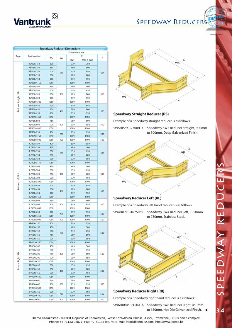
spe
ed
wa
y r
ed
uc
er
s
Speedway Reducers
34
Type Part Number
Dimensions mm
Wp WsX
YSW4 SW5 & SW6
Redu
cer S
trai
ght (
RS)
RS/300/150 300
150
339 350
500
RS/450/150 450 489 500
RS/600/150 600 639 650
RS/750/150 750 789 800
RS/900/150 900 939 950
RS/1050/150 1050 1089 1100
RS/450/300 450
300
489 500
500
RS/600/300 600 639 650
RS/750/300 750 789 800
RS/900/300 900 939 950
RS/1050/300 1050 1089 1100
RS/600/450 600
450
639 650
500RS/750/450 750 789 800
RS/900/450 900 939 950
RS/1050/450 1050 1089 1100
RS/750/600 750
600
789 800
500RS/900/600 900 939 950
RS/1050/600 1050 1089 1100
RS/900/750 900750
939 950500
RS/1050/750 1050 1089 1100
RS/1050/900 1050 900 1089 1100 500
Redu
cer L
eft (
RL)
RL/300/150 300
150
339 350
500
RL/450/150 450 489 500
RL/600/150 600 639 650
RL/750/150 750 789 800
RL/900/150 900 939 950
RL/1050/150 1050 1089 1100
RL/450/300 450
300
489 500
500
RL/600/300 600 639 650
RL/750/300 750 789 800
RL/900/300 900 939 950
RL/1050/300 1050 1089 1100
RL/600/450 600
450
639 650
500RL/750/450 750 789 800
RL/900/450 900 939 950
RL/1050/450 1050 1089 1100
RL/750/600 750
600
789 800
500RL/900/600 900 939 950
RL/1050/600 1050 1089 1100
RL/900/750 900750
939 950500
RL/1050/750 1050 1089 1100
RL/1050/900 1050 900 1089 1100 500
Redu
cer R
ight
(RR)
RR/300/150 300
150
339 350
500
RR/450/150 450 489 500
RR/600/150 600 639 650
RR/750/150 750 789 800
RR/900/150 900 939 950
RR/1050/150 1050 1089 1100
RR/450/300 450
300
489 500
500
RR/600/300 600 639 650
RR/750/300 750 789 800
RR/900/300 900 939 950
RR/1050/300 1050 1089 1100
RR/600/450 600
450
639 650
500RR/750/450 750 789 800
RR/900/450 900 939 950
RR/1050/450 1050 1089 1100
RR/750/600 750
600
789 800
500RR/900/600 900 939 950
RR/1050/600 1050 1089 1100
RR/900/750 900750
939 950500
RR/1050/750 1050 1089 1100
RR/1050/900 1050 900 1089 1100 500
Speedway Straight Reducer (RS)
Example of a Speedway straight reducer is as follows:
SW5/RS/900/300/GX Speedway SW5 Reducer Straight, 900mm to 300mm, Deep Galvanized Finish.
Speedway Reducer Left (RL)
Example of a Speedway left hand reducer is as follows:
SW4/RL/1050/750/SS Speedway SW4 Reducer Left, 1050mm to 750mm, Stainless Steel.
Speedway Reducer Right (RR)
Example of a Speedway right hand reducer is as follows:
SW6/RR/450/150/GA Speedway SW6 Reducer Right, 450mm to 150mm, Hot Dip Galvanized Finish.
XWp
WsY
XWp
Ws
Y
XWp
WsY
Speedway Reducer Dimensions
ibemo Kazakhstan - 090301 Republic of Kazakhstan, West Kazakhstan Oblast, Aksai, Pramzone, BKKS office complex Phone: +7 71133 93077; Fax: +7 71133 93074; E-Mail: [email protected]; http://www.ibemo.kz
ibemoIND
USTR
IA
L & ELECTRICAL EQUIPMENT
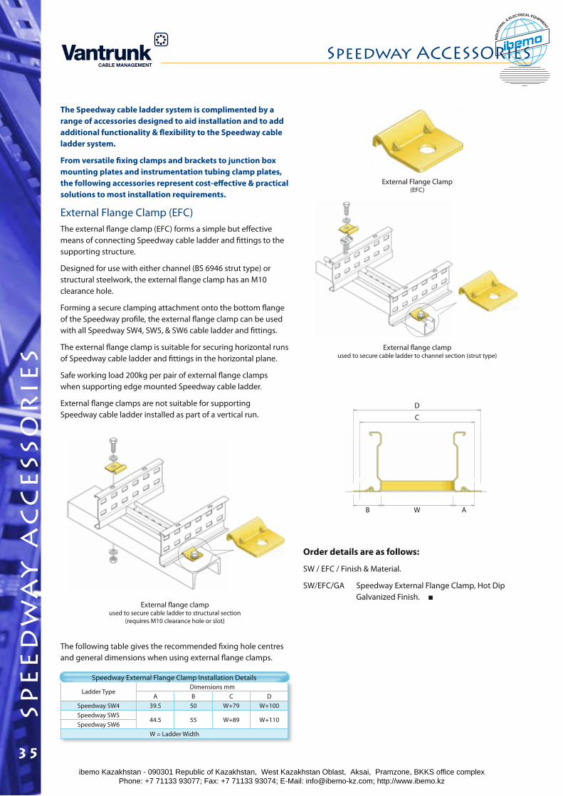
spe
ed
wa
y a
cc
ess
or
ies External flange clamp
used to secure cable ladder to channel section (strut type)
Ladder TypeDimensions mm
A B C DSpeedway SW4 39.5 50 W+79 W+100Speedway SW5
44.5 55 W+89 W+110Speedway SW6
W = Ladder Width
The Speedway cable ladder system is complimented by a range of accessories designed to aid installation and to add additional functionality & flexibility to the Speedway cable ladder system.
From versatile fixing clamps and brackets to junction box mounting plates and instrumentation tubing clamp plates, the following accessories represent cost-effective & practical solutions to most installation requirements.
External Flange Clamp (EFC)The external flange clamp (EFC) forms a simple but effective means of connecting Speedway cable ladder and fittings to the supporting structure.
Designed for use with either channel (BS 6946 strut type) or structural steelwork, the external flange clamp has an M10 clearance hole.
Forming a secure clamping attachment onto the bottom flange of the Speedway profile, the external flange clamp can be used with all Speedway SW4, SW5, & SW6 cable ladder and fittings.
The external flange clamp is suitable for securing horizontal runs of Speedway cable ladder and fittings in the horizontal plane.
Safe working load 200kg per pair of external flange clamps when supporting edge mounted Speedway cable ladder.
External flange clamps are not suitable for supporting Speedway cable ladder installed as part of a vertical run.
External Flange Clamp(EFC)
External flange clamp used to secure cable ladder to structural section
(requires M10 clearance hole or slot)
Speedway External Flange Clamp Installation Details
The following table gives the recommended fixing hole centres and general dimensions when using external flange clamps.
Order details are as follows:
SW / EFC / Finish & Material.
SW/EFC/GA Speedway External Flange Clamp, Hot Dip Galvanized Finish.
WB A
C
D
Speedway ACCESSORIES
35ibemo Kazakhstan - 090301 Republic of Kazakhstan, West Kazakhstan Oblast, Aksai, Pramzone, BKKS office complex Phone: +7 71133 93077; Fax: +7 71133 93074; E-Mail: [email protected]; http://www.ibemo.kz
ibemoIND
USTR
IA
L & ELECTRICAL EQUIPMENT
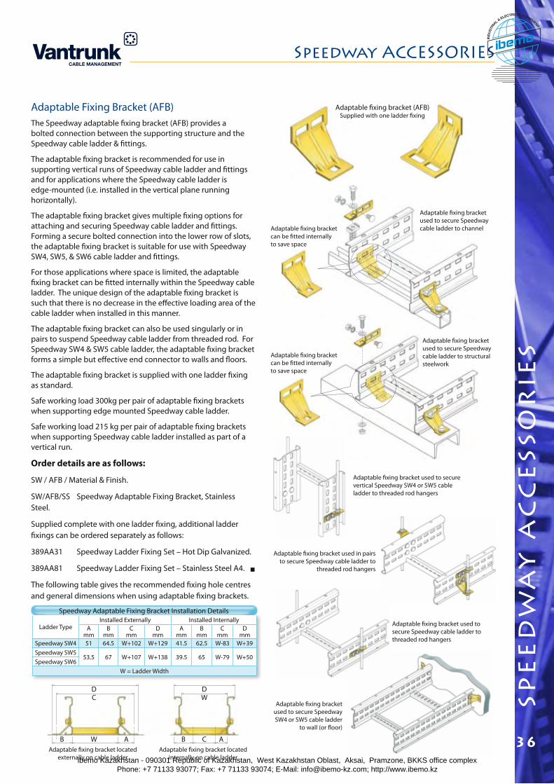
spe
ed
wa
y a
cc
ess
or
ies
Speedway ACCESSORIES
36
Adaptable Fixing Bracket (AFB)The Speedway adaptable fixing bracket (AFB) provides a bolted connection between the supporting structure and the Speedway cable ladder & fittings.
The adaptable fixing bracket is recommended for use in supporting vertical runs of Speedway cable ladder and fittings and for applications where the Speedway cable ladder is edge-mounted (i.e. installed in the vertical plane running horizontally).
The adaptable fixing bracket gives multiple fixing options for attaching and securing Speedway cable ladder and fittings. Forming a secure bolted connection into the lower row of slots, the adaptable fixing bracket is suitable for use with Speedway SW4, SW5, & SW6 cable ladder and fittings.
For those applications where space is limited, the adaptable fixing bracket can be fitted internally within the Speedway cable ladder. The unique design of the adaptable fixing bracket is such that there is no decrease in the effective loading area of the cable ladder when installed in this manner.
The adaptable fixing bracket can also be used singularly or in pairs to suspend Speedway cable ladder from threaded rod. For Speedway SW4 & SW5 cable ladder, the adaptable fixing bracket forms a simple but effective end connector to walls and floors.
The adaptable fixing bracket is supplied with one ladder fixing as standard.
Safe working load 300kg per pair of adaptable fixing brackets when supporting edge mounted Speedway cable ladder.
Safe working load 215 kg per pair of adaptable fixing brackets when supporting Speedway cable ladder installed as part of a vertical run.
Order details are as follows:
SW / AFB / Material & Finish.
SW/AFB/SS Speedway Adaptable Fixing Bracket, Stainless Steel.
Supplied complete with one ladder fixing, additional ladder fixings can be ordered separately as follows:
389AA31 Speedway Ladder Fixing Set – Hot Dip Galvanized.
389AA81 Speedway Ladder Fixing Set – Stainless Steel A4.
The following table gives the recommended fixing hole centres and general dimensions when using adaptable fixing brackets.
Ladder TypeInstalled Externally Installed Internally
A mm
B mm
Cmm
Dmm
A mm
B mm
Cmm
Dmm
Speedway SW4 51 64.5 W+102 W+129 41.5 62.5 W-83 W+39Speedway SW5
53.5 67 W+107 W+138 39.5 65 W-79 W+50Speedway SW6
W = Ladder Width
Speedway Adaptable Fixing Bracket Installation Details
WB A
CD
ACB
WD
Adaptable fixing bracket located externally on cable ladder
Adaptable fixing bracket located internally on cable ladder
Adaptable fixing bracket (AFB)Supplied with one ladder fixing
Adaptable fixing bracket used to secure Speedway cable ladder to channel
Adaptable fixing bracket used to secure Speedway cable ladder to structural steelwork
Adaptable fixing bracket used to secure vertical Speedway SW4 or SW5 cable ladder to threaded rod hangers
Adaptable fixing bracket used in pairs to secure Speedway cable ladder to
threaded rod hangers
Adaptable fixing bracket used to secure Speedway cable ladder to threaded rod hangers
Adaptable fixing bracket used to secure Speedway SW4 or SW5 cable ladder
to wall (or floor)
Adaptable fixing bracket can be fitted internally to save space
Adaptable fixing bracket can be fitted internally to save space
ibemo Kazakhstan - 090301 Republic of Kazakhstan, West Kazakhstan Oblast, Aksai, Pramzone, BKKS office complex Phone: +7 71133 93077; Fax: +7 71133 93074; E-Mail: [email protected]; http://www.ibemo.kz
ibemoIND
USTR
IA
L & ELECTRICAL EQUIPMENT
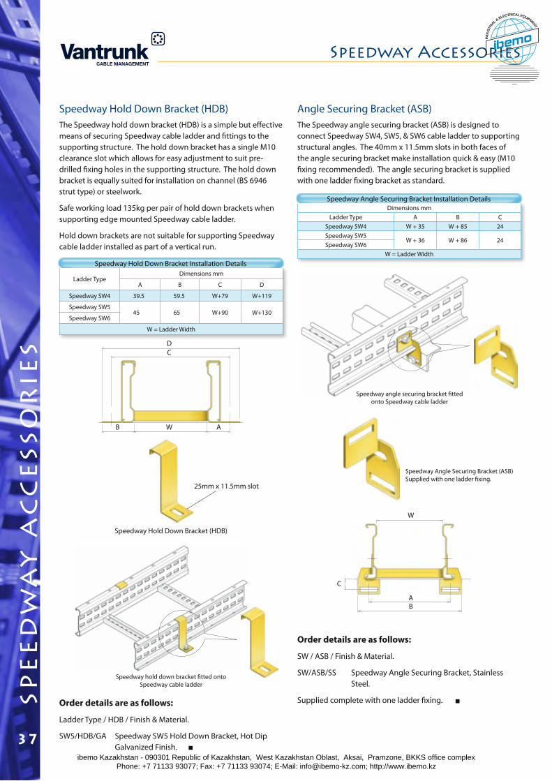
Dimensions mmLadder Type A B C
Speedway SW4 W + 35 W + 85 24Speedway SW5
W + 36 W + 86 24Speedway SW6
W = Ladder Width
Ladder TypeDimensions mm
A B C D
Speedway SW4 39.5 59.5 W+79 W+119
Speedway SW545 65 W+90 W+130
Speedway SW6
W = Ladder Width
Speedway Hold Down Bracket (HDB)The Speedway hold down bracket (HDB) is a simple but effective means of securing Speedway cable ladder and fittings to the supporting structure. The hold down bracket has a single M10 clearance slot which allows for easy adjustment to suit pre-drilled fixing holes in the supporting structure. The hold down bracket is equally suited for installation on channel (BS 6946 strut type) or steelwork.
Safe working load 135kg per pair of hold down brackets when supporting edge mounted Speedway cable ladder.
Hold down brackets are not suitable for supporting Speedway cable ladder installed as part of a vertical run.
Speedway Hold Down Bracket Installation Details
WB A
CD
Order details are as follows:
Ladder Type / HDB / Finish & Material.
SW5/HDB/GA Speedway SW5 Hold Down Bracket, Hot Dip Galvanized Finish.
Speedway Hold Down Bracket (HDB)
25mm x 11.5mm slot
Speedway hold down bracket fitted onto Speedway cable ladder
Angle Securing Bracket (ASB)The Speedway angle securing bracket (ASB) is designed to connect Speedway SW4, SW5, & SW6 cable ladder to supporting structural angles. The 40mm x 11.5mm slots in both faces of the angle securing bracket make installation quick & easy (M10 fixing recommended). The angle securing bracket is supplied with one ladder fixing bracket as standard.
Speedway Angle Securing Bracket Installation Details
Order details are as follows:
SW / ASB / Finish & Material.
SW/ASB/SS Speedway Angle Securing Bracket, Stainless Steel.
Supplied complete with one ladder fixing.
Speedway Angle Securing Bracket (ASB)Supplied with one ladder fixing.
Speedway angle securing bracket fitted onto Speedway cable ladder
BA
W
C
spe
ed
wa
y a
cc
ess
or
ies
Speedway Accessories
37ibemo Kazakhstan - 090301 Republic of Kazakhstan, West Kazakhstan Oblast, Aksai, Pramzone, BKKS office complex Phone: +7 71133 93077; Fax: +7 71133 93074; E-Mail: [email protected]; http://www.ibemo.kz
ibemoIND
USTR
IA
L & ELECTRICAL EQUIPMENT
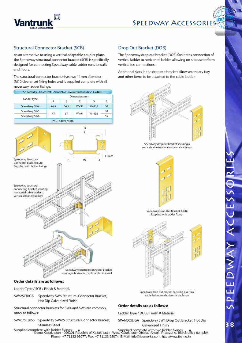
spe
ed
wa
y a
cc
ess
or
ies
Speedway Accessories
38
Ladder TypeDimensions mm
A B C D E
Speedway SW4 46.5 66.5 W+93 W+133 30
Speedway SW547 67 W+94 W+134
30
Speedway SW6 55
W = Ladder Width
Structural Connector Bracket (SCB)As an alternative to using a vertical adaptable coupler plate, the Speedway structural connector bracket (SCB) is specifically designed for connecting Speedway cable ladder runs to walls and floors.
The structural connector bracket has two 11mm diameter (M10 clearance) fixing holes and is supplied complete with all necessary ladder fixings.
Speedway Strucrural Connector Bracket Installation Details
Order details are as follows:
Ladder Type / SCB / Finish & Material.
SW6/SCB/GA Speedway SW6 Structural Connector Bracket, Hot Dip Galvanized Finish.
Structural connector brackets for SW4 and SW5 are common, order as follows:
SW45/SCB/SS Speedway SW4/5 Structural Connector Bracket, Stainless Steel Supplied complete with ladder fixings.
Drop Out Bracket (DOB)The Speedway drop out bracket (DOB) facilitates connection of vertical ladder to horizontal ladder, allowing on-site use to form vertical tee connections.
Additional slots in the drop out bracket allow secondary tray and other items to be attached to the cable ladder.
Speedway drop out bracket securing a vertical cable ladder to a horizontal cable run
Speedway Drop Out Bracket (DOB)Supplied with ladder fixings
Speedway drop out bracket securing a vertical cable tray to a horizontal cable run
DC
WB A
E
11mm
Order details are as follows:
Ladder Type / DOB / Finish & Material.
SW4/DOB/GA Speedway SW4 Drop Out Bracket, Hot Dip Galvanized Finish Supplied complete with two ladder fixings.
Speedway structural connecting bracket securing horizontal cable ladder to vertical channel support
Speedway structural connector bracket securing a horizontal cable ladder to a wall
Speedway Structural Connector Bracket (SCB)Supplied with ladder fixings
ibemo Kazakhstan - 090301 Republic of Kazakhstan, West Kazakhstan Oblast, Aksai, Pramzone, BKKS office complex Phone: +7 71133 93077; Fax: +7 71133 93074; E-Mail: [email protected]; http://www.ibemo.kz
ibemoIND
USTR
IA
L & ELECTRICAL EQUIPMENT
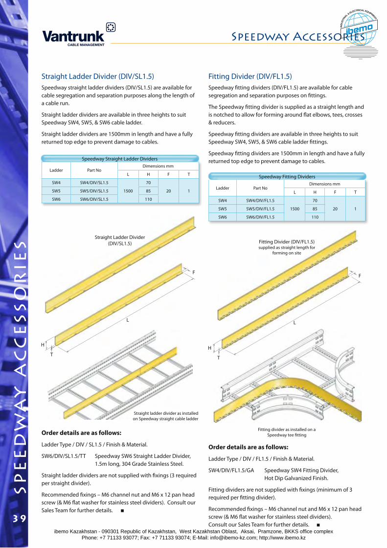
Ladder Part NoDimensions mm
L H F T
SW4 SW4/DIV/FL1.5
1500
70
20 1SW5 SW5/DIV/FL1.5 85
SW6 SW6/DIV/FL1.5 110
Ladder Part NoDimensions mm
L H F T
SW4 SW4/DIV/SL1.5
1500
70
20 1SW5 SW5/DIV/SL1.5 85
SW6 SW6/DIV/SL1.5 110
Straight Ladder Divider (DIV/SL1.5)Speedway straight ladder dividers (DIV/SL1.5) are available for cable segregation and separation purposes along the length of a cable run.
Straight ladder dividers are available in three heights to suit Speedway SW4, SW5, & SW6 cable ladder.
Straight ladder dividers are 1500mm in length and have a fully returned top edge to prevent damage to cables.
Speedway Straight Ladder Dividers
Order details are as follows:
Ladder Type / DIV / SL1.5 / Finish & Material.
SW6/DIV/SL1.5/TT Speedway SW6 Straight Ladder Divider, 1.5m long, 304 Grade Stainless Steel.
Straight ladder dividers are not supplied with fixings (3 required per straight divider).
Recommended fixings – M6 channel nut and M6 x 12 pan head screw (& M6 flat washer for stainless steel dividers). Consult our Sales Team for further details.
Straight Ladder Divider(DIV/SL1.5)
Straight ladder divider as installed on Speedway straight cable ladder
H
T
L
F
Fitting Divider (DIV/FL1.5)Speedway fitting dividers (DIV/FL1.5) are available for cable segregation and separation purposes on fittings.
The Speedway fitting divider is supplied as a straight length and is notched to allow for forming around flat elbows, tees, crosses & reducers.
Speedway fitting dividers are available in three heights to suit Speedway SW4, SW5, & SW6 cable ladder fittings.
Speedway fitting dividers are 1500mm in length and have a fully returned top edge to prevent damage to cables.
Speedway Fitting Dividers
Order details are as follows:
Ladder Type / DIV / FL1.5 / Finish & Material.
SW4/DIV/FL1.5/GA Speedway SW4 Fitting Divider, Hot Dip Galvanized Finish.
Fitting dividers are not supplied with fixings (minimum of 3 required per fitting divider).
Recommended fixings – M6 channel nut and M6 x 12 pan head screw (& M6 flat washer for stainless steel dividers). Consult our Sales Team for further details.
Fitting Divider (DIV/FL1.5)supplied as straight length for
forming on site
H
T
L
F
Fitting divider as installed on a Speedway tee fitting
spe
ed
wa
y a
cc
ess
or
ies
Speedway Accessories
39ibemo Kazakhstan - 090301 Republic of Kazakhstan, West Kazakhstan Oblast, Aksai, Pramzone, BKKS office complex Phone: +7 71133 93077; Fax: +7 71133 93074; E-Mail: [email protected]; http://www.ibemo.kz
ibemoIND
USTR
IA
L & ELECTRICAL EQUIPMENT
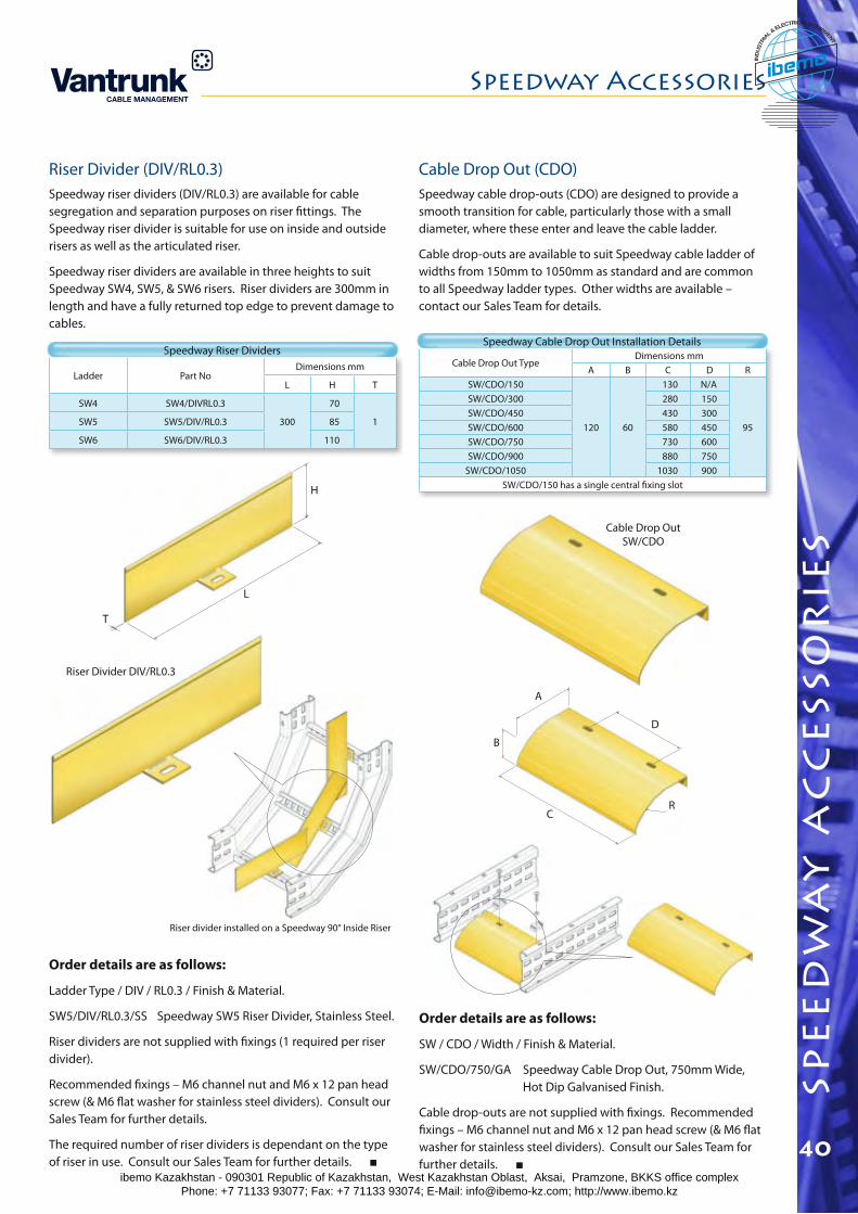
spe
ed
wa
y a
cc
ess
or
ies
Speedway Accessories
40
H
L
T
Cable Drop Out TypeDimensions mm
A B C D RSW/CDO/150
120 60
130 N/A
95
SW/CDO/300 280 150SW/CDO/450 430 300SW/CDO/600 580 450SW/CDO/750 730 600SW/CDO/900 880 750
SW/CDO/1050 1030 900SW/CDO/150 has a single central fixing slot
Ladder Part NoDimensions mm
L H T
SW4 SW4/DIVRL0.3
300
70
1SW5 SW5/DIV/RL0.3 85
SW6 SW6/DIV/RL0.3 110
Riser Divider (DIV/RL0.3)Speedway riser dividers (DIV/RL0.3) are available for cable segregation and separation purposes on riser fittings. The Speedway riser divider is suitable for use on inside and outside risers as well as the articulated riser.
Speedway riser dividers are available in three heights to suit Speedway SW4, SW5, & SW6 risers. Riser dividers are 300mm in length and have a fully returned top edge to prevent damage to cables.
Order details are as follows:
Ladder Type / DIV / RL0.3 / Finish & Material.
SW5/DIV/RL0.3/SS Speedway SW5 Riser Divider, Stainless Steel.
Riser dividers are not supplied with fixings (1 required per riser divider).
Recommended fixings – M6 channel nut and M6 x 12 pan head screw (& M6 flat washer for stainless steel dividers). Consult our Sales Team for further details.
The required number of riser dividers is dependant on the type of riser in use. Consult our Sales Team for further details.
Riser divider installed on a Speedway 90° Inside Riser
Riser Divider DIV/RL0.3
Speedway Riser Dividers
Cable Drop Out (CDO)Speedway cable drop-outs (CDO) are designed to provide a smooth transition for cable, particularly those with a small diameter, where these enter and leave the cable ladder.
Cable drop-outs are available to suit Speedway cable ladder of widths from 150mm to 1050mm as standard and are common to all Speedway ladder types. Other widths are available – contact our Sales Team for details.
Speedway Cable Drop Out Installation Details
Order details are as follows:
SW / CDO / Width / Finish & Material.
SW/CDO/750/GA Speedway Cable Drop Out, 750mm Wide, Hot Dip Galvanised Finish.
Cable drop-outs are not supplied with fixings. Recommended fixings – M6 channel nut and M6 x 12 pan head screw (& M6 flat washer for stainless steel dividers). Consult our Sales Team for further details.
Cable Drop Out SW/CDO
A
B
C
D
R
ibemo Kazakhstan - 090301 Republic of Kazakhstan, West Kazakhstan Oblast, Aksai, Pramzone, BKKS office complex Phone: +7 71133 93077; Fax: +7 71133 93074; E-Mail: [email protected]; http://www.ibemo.kz
ibemoIND
USTR
IA
L & ELECTRICAL EQUIPMENT
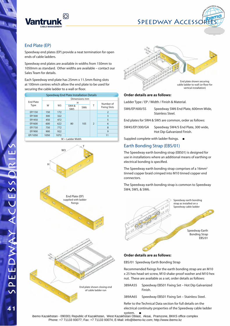
End Plate Type
Dimensions mm
W W3H
T Number of Fixing SlotsSW4 &
SW5 SW6
EP/150 150 172
80 105 2
2EP/300 300 322 3EP/450 450 472 5EP/600 600 622 6EP/750 750 772 8EP/900 900 922 9
EP/1050 1050 1072 11W = Ladder Width
End Plate (EP)Speedway end plates (EP) provide a neat termination for open ends of cable ladders.
Speedway end plates are available in widths from 150mm to 1050mm as standard. Other widths are available – contact our Sales Team for details.
Each Speedway end plate has 25mm x 11.5mm fixing slots at 100mm centres which allow the end plate to be used for securing the cable ladder to a wall or floor.
Speedway End Plate Installation Details Order details are as follows:
Ladder Type / EP / Width / Finish & Material.
SW6/EP/600/SS Speedway SW6 End Plate, 600mm Wide, Stainless Steel.
End plates for SW4 & SW5 are common, order as follows:
SW45/EP/300/GA Speedway SW4/5 End Plate, 300 wide, Hot Dip Galvanized Finish.
Suppled complete with ladder fixings.
End Plate (EP)supplied with ladder
fixings
End plate shown closing end of cable ladder run
End plate shown securing cable ladder to wall (or floor for
vertical installation)
H
W3T Earth Bonding Strap (EBS/01)
The Speedway earth bonding strap (EBS01) is designed for use in installations where an additional means of earthing or electrical bonding is specified.
The Speedway earth bonding strap comprises of a 16mm2 tinned copper braid crimped into M10 tinned copper end connectors.
The Speedway earth bonding strap is common to Speedway SW4, SW5, & SW6.
Order details are as follows:
EBS/01 Speedway Earth Bonding Strap
Recommended fixings for the earth bonding strap are an M10 x 25 hex head set screw, M10 shake-proof washer and M10 hex nut. These are available as a set, order details as follows:
389AA55 Speedway EBS01 Fixing Set – Hot Dip Galvanized Finish.
389AA65 Speedway EBS01 Fixing Set – Stainless Steel.
Refer to the Technical Data section for full details on the electrical continuity properties of the Speedway cable ladder system.
Speedway earth bonding strap as installed on a Speedway cable ladder
Speedway Earth Bonding Strap
EBS/01
spe
ed
wa
y a
cc
ess
or
ies
Speedway Accessories
41ibemo Kazakhstan - 090301 Republic of Kazakhstan, West Kazakhstan Oblast, Aksai, Pramzone, BKKS office complex Phone: +7 71133 93077; Fax: +7 71133 93074; E-Mail: [email protected]; http://www.ibemo.kz
ibemoIND
USTR
IA
L & ELECTRICAL EQUIPMENT
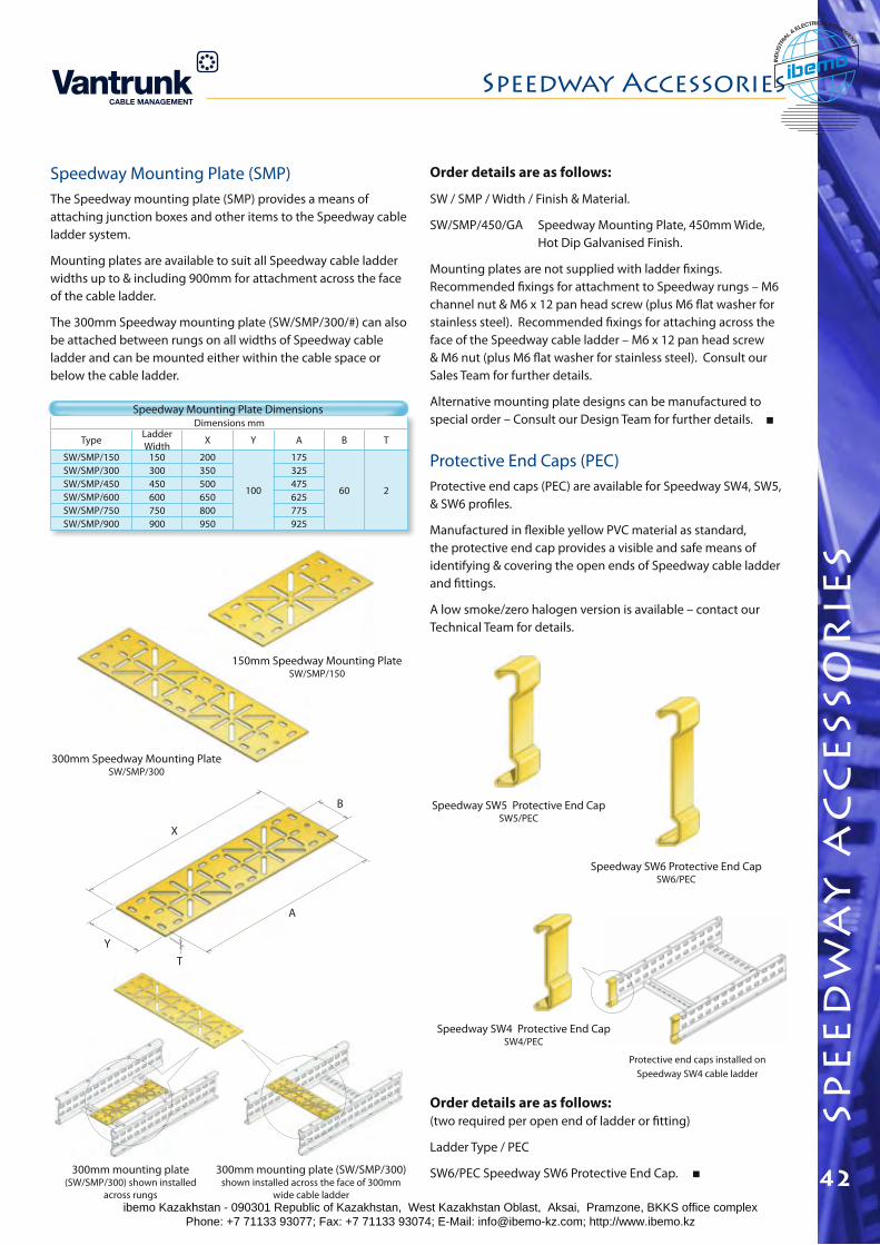
spe
ed
wa
y a
cc
ess
or
ies
Speedway Accessories
42
Dimensions mm
Type Ladder Width X Y A B T
SW/SMP/150 150 200
100
175
60 2
SW/SMP/300 300 350 325SW/SMP/450 450 500 475SW/SMP/600 600 650 625SW/SMP/750 750 800 775SW/SMP/900 900 950 925
Speedway Mounting Plate (SMP)The Speedway mounting plate (SMP) provides a means of attaching junction boxes and other items to the Speedway cable ladder system.
Mounting plates are available to suit all Speedway cable ladder widths up to & including 900mm for attachment across the face of the cable ladder.
The 300mm Speedway mounting plate (SW/SMP/300/#) can also be attached between rungs on all widths of Speedway cable ladder and can be mounted either within the cable space or below the cable ladder.
Speedway Mounting Plate Dimensions
Order details are as follows:
SW / SMP / Width / Finish & Material.
SW/SMP/450/GA Speedway Mounting Plate, 450mm Wide, Hot Dip Galvanised Finish.
Mounting plates are not supplied with ladder fixings. Recommended fixings for attachment to Speedway rungs – M6 channel nut & M6 x 12 pan head screw (plus M6 flat washer for stainless steel). Recommended fixings for attaching across the face of the Speedway cable ladder – M6 x 12 pan head screw & M6 nut (plus M6 flat washer for stainless steel). Consult our Sales Team for further details.
Alternative mounting plate designs can be manufactured to special order – Consult our Design Team for further details.
300mm mounting plate (SW/SMP/300) shown installed across the face of 300mm
wide cable ladder
300mm mounting plate (SW/SMP/300) shown installed
across rungs
300mm Speedway Mounting PlateSW/SMP/300
150mm Speedway Mounting PlateSW/SMP/150
YT
X
B
A
Protective End Caps (PEC)Protective end caps (PEC) are available for Speedway SW4, SW5, & SW6 profiles.
Manufactured in flexible yellow PVC material as standard, the protective end cap provides a visible and safe means of identifying & covering the open ends of Speedway cable ladder and fittings.
A low smoke/zero halogen version is available – contact our Technical Team for details.
Speedway SW4 Protective End CapSW4/PEC
Protective end caps installed on Speedway SW4 cable ladder
Order details are as follows: (two required per open end of ladder or fitting)
Ladder Type / PEC
SW6/PEC Speedway SW6 Protective End Cap.
Speedway SW6 Protective End CapSW6/PEC
Speedway SW5 Protective End CapSW5/PEC
ibemo Kazakhstan - 090301 Republic of Kazakhstan, West Kazakhstan Oblast, Aksai, Pramzone, BKKS office complex Phone: +7 71133 93077; Fax: +7 71133 93074; E-Mail: [email protected]; http://www.ibemo.kz
ibemoIND
USTR
IA
L & ELECTRICAL EQUIPMENT
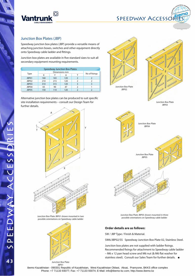
TypeDimensions mm
No of fixingsX Y A T
JBP01 160 165 120 2 2JBP02 210 215 120 2 2JBP03 310 315 120 3 3JBP04 65 90 47 2 1JBP05 150 110 120 2 2
Junction Box Plates (JBP)Speedway junction box plates (JBP) provide a versatile means of attaching junction boxes, switches and other equipment directly onto Speedway cable ladder and fittings.
Junction box plates are available in five standard sizes to suit all secondary equipment mounting requirements.
Speedway Junction Box Plates
Junction Box Plate JBP01
Junction Box Plate JBP02
Junction Box Plate JBP03
Junction Box Plate JBP04
Junction Box Plate JBP05
Junction Box Plate JBP05 shown mounted in three possible orientations on Speedway cable ladderJunction Box Plate JBP01 shown mounted in two
possible orientations on Speedway cable ladder
T
A
X
Y
Order details are as follows:
SW / JBP Type / Finish & Material.
SW6/JBP02/SS Speedway Junction Box Plate 02, Stainless Steel.
Junction box plates are not supplied with ladder fixings. Recommended fixings for attachment to Speedway cable ladder – M6 x 12 pan head screw and M6 nut (& M6 flat washer for stainless steel). Consult our Sales Team for further details.
Alternative junction box plates can be produced to suit specific site installation requirements – consult our Design Team for further details.
spe
ed
wa
y a
cc
ess
or
ies
Speedway Accessories
43ibemo Kazakhstan - 090301 Republic of Kazakhstan, West Kazakhstan Oblast, Aksai, Pramzone, BKKS office complex Phone: +7 71133 93077; Fax: +7 71133 93074; E-Mail: [email protected]; http://www.ibemo.kz
ibemoIND
USTR
IA
L & ELECTRICAL EQUIPMENT
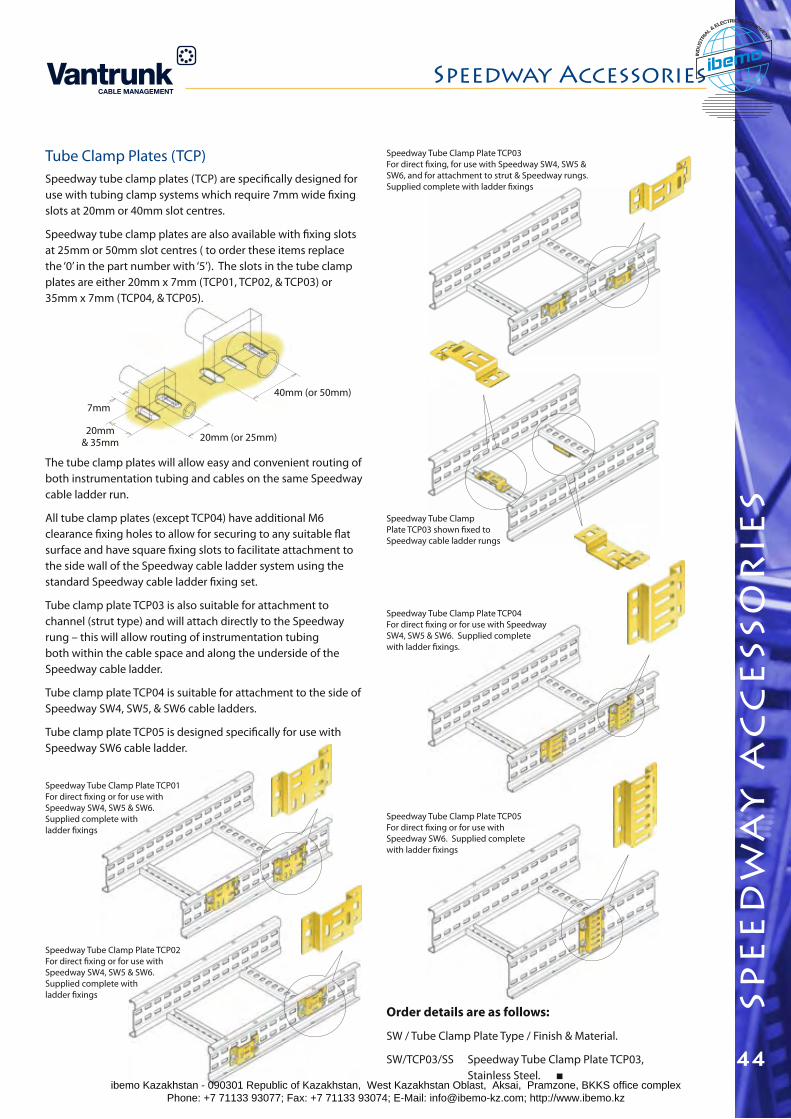
spe
ed
wa
y a
cc
ess
or
ies
Speedway Accessories
44
Order details are as follows:
SW / Tube Clamp Plate Type / Finish & Material.
SW/TCP03/SS Speedway Tube Clamp Plate TCP03, Stainless Steel.
Speedway Tube Clamp Plate TCP03For direct fixing, for use with Speedway SW4, SW5 & SW6, and for attachment to strut & Speedway rungs.Supplied complete with ladder fixings
Speedway Tube Clamp Plate TCP05For direct fixing or for use with Speedway SW6. Supplied complete with ladder fixings
Speedway Tube Clamp Plate TCP04For direct fixing or for use with Speedway SW4, SW5 & SW6. Supplied complete with ladder fixings.
Speedway Tube Clamp Plate TCP03 shown fixed to Speedway cable ladder rungs
Tube Clamp Plates (TCP)Speedway tube clamp plates (TCP) are specifically designed for use with tubing clamp systems which require 7mm wide fixing slots at 20mm or 40mm slot centres.
Speedway tube clamp plates are also available with fixing slots at 25mm or 50mm slot centres ( to order these items replace the ‘0’ in the part number with ‘5’). The slots in the tube clamp plates are either 20mm x 7mm (TCP01, TCP02, & TCP03) or 35mm x 7mm (TCP04, & TCP05).
The tube clamp plates will allow easy and convenient routing of both instrumentation tubing and cables on the same Speedway cable ladder run.
All tube clamp plates (except TCP04) have additional M6 clearance fixing holes to allow for securing to any suitable flat surface and have square fixing slots to facilitate attachment to the side wall of the Speedway cable ladder system using the standard Speedway cable ladder fixing set.
Tube clamp plate TCP03 is also suitable for attachment to channel (strut type) and will attach directly to the Speedway rung – this will allow routing of instrumentation tubing both within the cable space and along the underside of the Speedway cable ladder.
Tube clamp plate TCP04 is suitable for attachment to the side of Speedway SW4, SW5, & SW6 cable ladders.
Tube clamp plate TCP05 is designed specifically for use with Speedway SW6 cable ladder.
7mm
20mm& 35mm 20mm (or 25mm)
40mm (or 50mm)
Speedway Tube Clamp Plate TCP01 For direct fixing or for use with Speedway SW4, SW5 & SW6. Supplied complete with ladder fixings
Speedway Tube Clamp Plate TCP02For direct fixing or for use with Speedway SW4, SW5 & SW6. Supplied complete with ladder fixings
ibemo Kazakhstan - 090301 Republic of Kazakhstan, West Kazakhstan Oblast, Aksai, Pramzone, BKKS office complex Phone: +7 71133 93077; Fax: +7 71133 93074; E-Mail: [email protected]; http://www.ibemo.kz
ibemoIND
USTR
IA
L & ELECTRICAL EQUIPMENT
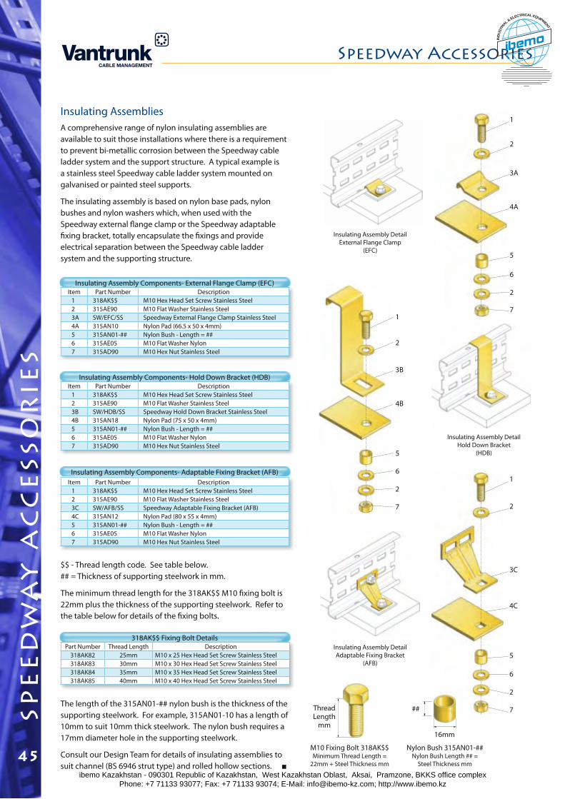
7
2
6
5
4C
3C
2
1
Item Part Number Description1 318AK$$ M10 Hex Head Set Screw Stainless Steel 2 315AE90 M10 Flat Washer Stainless Steel 3B SW/HDB/SS Speedway Hold Down Bracket Stainless Steel4B 315AN18 Nylon Pad (75 x 50 x 4mm)5 315AN01-## Nylon Bush - Length = ##6 315AE05 M10 Flat Washer Nylon7 315AD90 M10 Hex Nut Stainless Steel
Part Number Thread Length Description318AK82 25mm M10 x 25 Hex Head Set Screw Stainless Steel 318AK83 30mm M10 x 30 Hex Head Set Screw Stainless Steel 318AK84 35mm M10 x 35 Hex Head Set Screw Stainless Steel 318AK85 40mm M10 x 40 Hex Head Set Screw Stainless Steel
Item Part Number Description1 318AK$$ M10 Hex Head Set Screw Stainless Steel 2 315AE90 M10 Flat Washer Stainless Steel 3A SW/EFC/SS Speedway External Flange Clamp Stainless Steel 4A 315AN10 Nylon Pad (66.5 x 50 x 4mm)5 315AN01-## Nylon Bush - Length = ##6 315AE05 M10 Flat Washer Nylon7 315AD90 M10 Hex Nut Stainless Steel
Item Part Number Description1 318AK$$ M10 Hex Head Set Screw Stainless Steel 2 315AE90 M10 Flat Washer Stainless Steel 3C SW/AFB/SS Speedway Adaptable Fixing Bracket (AFB) 4C 315AN12 Nylon Pad (80 x 55 x 4mm)5 315AN01-## Nylon Bush - Length = ##6 315AE05 M10 Flat Washer Nylon7 315AD90 M10 Hex Nut Stainless Steel
The minimum thread length for the 318AK$$ M10 fixing bolt is 22mm plus the thickness of the supporting steelwork. Refer to the table below for details of the fixing bolts.
The length of the 315AN01-## nylon bush is the thickness of the supporting steelwork. For example, 315AN01-10 has a length of 10mm to suit 10mm thick steelwork. The nylon bush requires a 17mm diameter hole in the supporting steelwork.
Consult our Design Team for details of insulating assemblies to suit channel (BS 6946 strut type) and rolled hollow sections.
$$ - Thread length code. See table below.## = Thickness of supporting steelwork in mm.
Insulating Assembly Components- External Flange Clamp (EFC)
Insulating Assembly Components- Hold Down Bracket (HDB)
318AK$$ Fixing Bolt Details
Insulating Assembly Components- Adaptable Fixing Bracket (AFB)
Insulating AssembliesA comprehensive range of nylon insulating assemblies are available to suit those installations where there is a requirement to prevent bi-metallic corrosion between the Speedway cable ladder system and the support structure. A typical example is a stainless steel Speedway cable ladder system mounted on galvanised or painted steel supports.
The insulating assembly is based on nylon base pads, nylon bushes and nylon washers which, when used with the Speedway external flange clamp or the Speedway adaptable fixing bracket, totally encapsulate the fixings and provide electrical separation between the Speedway cable ladder system and the supporting structure.
Insulating Assembly DetailAdaptable Fixing Bracket
(AFB)
Insulating Assembly DetailExternal Flange Clamp
(EFC)
M10 Fixing Bolt 318AK$$Minimum Thread Length =
22mm + Steel Thickness mm
Nylon Bush 315AN01-##Nylon Bush Length ## =
Steel Thickness mm
Thread Length
mm
##
16mm
7
2
6
5
4B
3B
2
1
2
6
5
4A
3A
2
1
7
Insulating Assembly Detail Hold Down Bracket
(HDB)
spe
ed
wa
y a
cc
ess
or
ies
Speedway Accessories
45ibemo Kazakhstan - 090301 Republic of Kazakhstan, West Kazakhstan Oblast, Aksai, Pramzone, BKKS office complex Phone: +7 71133 93077; Fax: +7 71133 93074; E-Mail: [email protected]; http://www.ibemo.kz
ibemoIND
USTR
IA
L & ELECTRICAL EQUIPMENT
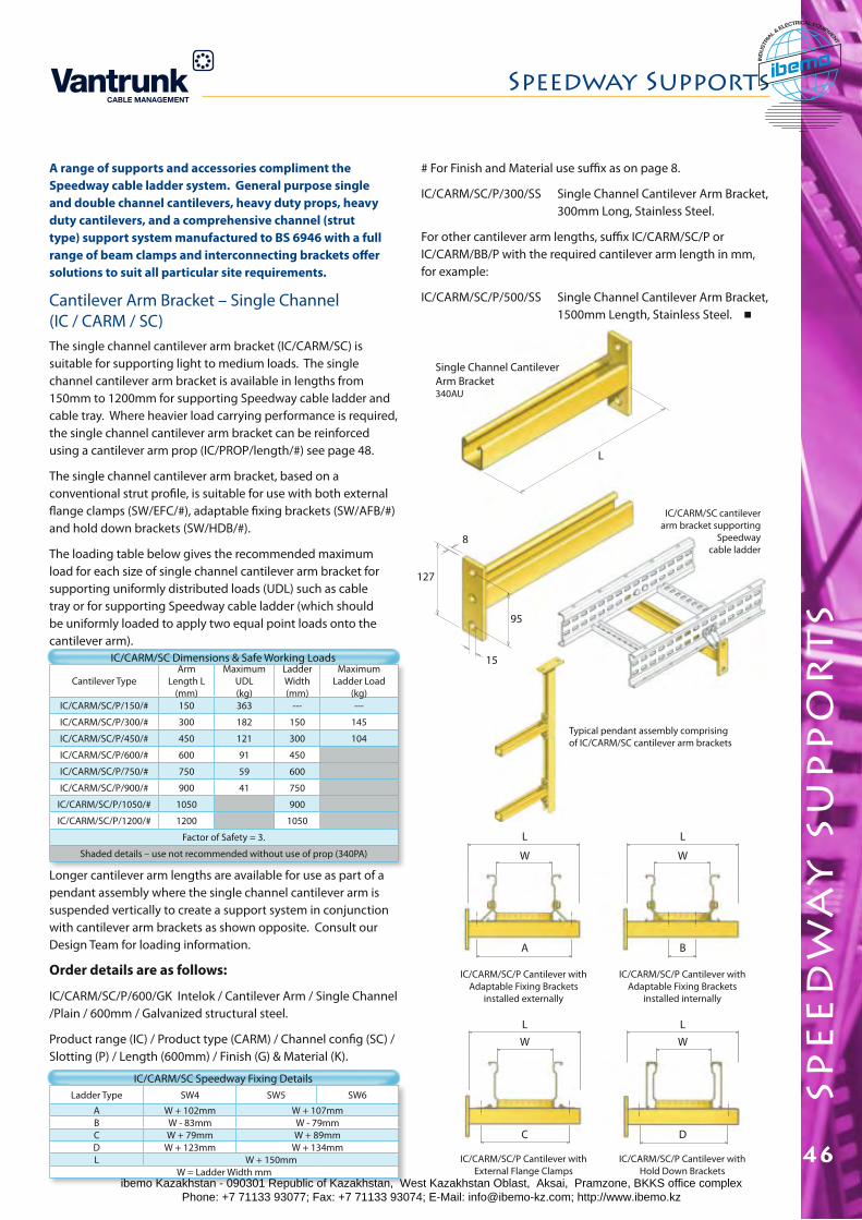
spe
ed
wa
y s
up
po
rt
s
Speedway Supports
46
A range of supports and accessories compliment the Speedway cable ladder system. General purpose single and double channel cantilevers, heavy duty props, heavy duty cantilevers, and a comprehensive channel (strut type) support system manufactured to BS 6946 with a full range of beam clamps and interconnecting brackets offer solutions to suit all particular site requirements.
Cantilever Arm Bracket – Single Channel (IC / CARM / SC)The single channel cantilever arm bracket (IC/CARM/SC) is suitable for supporting light to medium loads. The single channel cantilever arm bracket is available in lengths from 150mm to 1200mm for supporting Speedway cable ladder and cable tray. Where heavier load carrying performance is required, the single channel cantilever arm bracket can be reinforced using a cantilever arm prop (IC/PROP/length/#) see page 48.
The single channel cantilever arm bracket, based on a conventional strut profile, is suitable for use with both external flange clamps (SW/EFC/#), adaptable fixing brackets (SW/AFB/#) and hold down brackets (SW/HDB/#).
The loading table below gives the recommended maximum load for each size of single channel cantilever arm bracket for supporting uniformly distributed loads (UDL) such as cable tray or for supporting Speedway cable ladder (which should be uniformly loaded to apply two equal point loads onto the cantilever arm).
Cantilever TypeArm
Length L (mm)
Maximum UDL (kg)
Ladder Width (mm)
Maximum Ladder Load
(kg)IC/CARM/SC/P/150/# 150 363 --- ---
IC/CARM/SC/P/300/# 300 182 150 145
IC/CARM/SC/P/450/# 450 121 300 104
IC/CARM/SC/P/600/# 600 91 450
IC/CARM/SC/P/750/# 750 59 600
IC/CARM/SC/P/900/# 900 41 750
IC/CARM/SC/P/1050/# 1050 900
IC/CARM/SC/P/1200/# 1200 1050
Factor of Safety = 3.
Shaded details – use not recommended without use of prop (340PA)
IC/CARM/SC Dimensions & Safe Working Loads
Longer cantilever arm lengths are available for use as part of a pendant assembly where the single channel cantilever arm is suspended vertically to create a support system in conjunction with cantilever arm brackets as shown opposite. Consult our Design Team for loading information.
Order details are as follows:
IC/CARM/SC/P/600/GK Intelok / Cantilever Arm / Single Channel /Plain / 600mm / Galvanized structural steel.
Product range (IC) / Product type (CARM) / Channel config (SC) / Slotting (P) / Length (600mm) / Finish (G) & Material (K).
# For Finish and Material use suffix as on page 8.
IC/CARM/SC/P/300/SS Single Channel Cantilever Arm Bracket, 300mm Long, Stainless Steel.
For other cantilever arm lengths, suffix IC/CARM/SC/P or IC/CARM/BB/P with the required cantilever arm length in mm, for example:
IC/CARM/SC/P/500/SS Single Channel Cantilever Arm Bracket, 1500mm Length, Stainless Steel.
Ladder Type SW4 SW5 SW6
A W + 102mm W + 107mmB W - 83mm W - 79mmC W + 79mm W + 89mmD W + 123mm W + 134mmL W + 150mm
W = Ladder Width mm
IC/CARM/SC Speedway Fixing Details
IC/CARM/SC/P Cantilever with Adaptable Fixing Brackets
installed internally
Single Channel Cantilever Arm Bracket 340AU
IC/CARM/SC cantilever arm bracket supporting
Speedway cable ladder
Typical pendant assembly comprising of IC/CARM/SC cantilever arm brackets
IC/CARM/SC/P Cantilever with External Flange Clamps
IC/CARM/SC/P Cantilever with Adaptable Fixing Brackets
installed externally
15
95
127
8
LW
C
W
D
L
L
L
W
A
W
B
L
IC/CARM/SC/P Cantilever with Hold Down Brackets
ibemo Kazakhstan - 090301 Republic of Kazakhstan, West Kazakhstan Oblast, Aksai, Pramzone, BKKS office complex Phone: +7 71133 93077; Fax: +7 71133 93074; E-Mail: [email protected]; http://www.ibemo.kz
ibemoIND
USTR
IA
L & ELECTRICAL EQUIPMENT
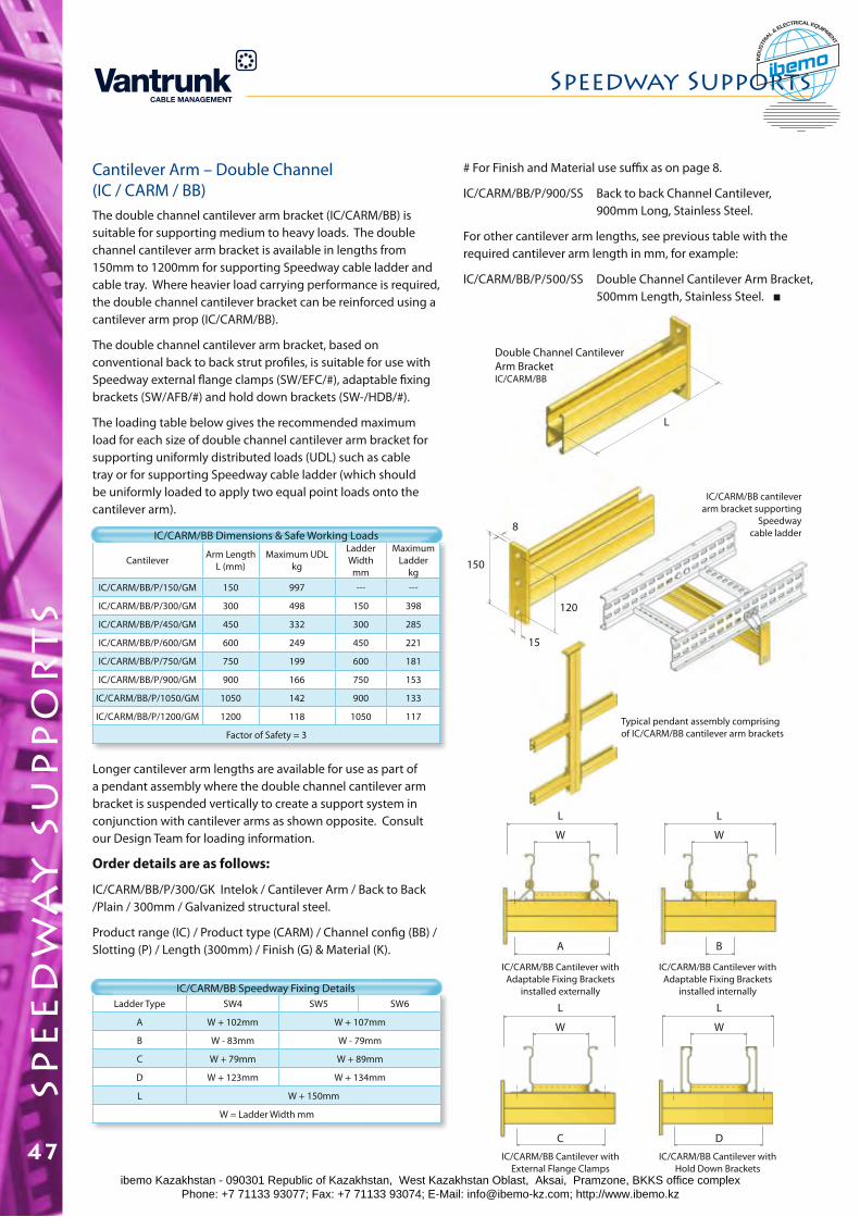
Cantilever Arm – Double Channel (IC / CARM / BB)The double channel cantilever arm bracket (IC/CARM/BB) is suitable for supporting medium to heavy loads. The double channel cantilever arm bracket is available in lengths from 150mm to 1200mm for supporting Speedway cable ladder and cable tray. Where heavier load carrying performance is required, the double channel cantilever bracket can be reinforced using a cantilever arm prop (IC/CARM/BB).
The double channel cantilever arm bracket, based on conventional back to back strut profiles, is suitable for use with Speedway external flange clamps (SW/EFC/#), adaptable fixing brackets (SW/AFB/#) and hold down brackets (SW-/HDB/#).
The loading table below gives the recommended maximum load for each size of double channel cantilever arm bracket for supporting uniformly distributed loads (UDL) such as cable tray or for supporting Speedway cable ladder (which should be uniformly loaded to apply two equal point loads onto the cantilever arm).
Cantilever Arm Length L (mm)
Maximum UDL kg
Ladder Width mm
Maximum Ladder
kgIC/CARM/BB/P/150/GM 150 997 --- ---
IC/CARM/BB/P/300/GM 300 498 150 398
IC/CARM/BB/P/450/GM 450 332 300 285
IC/CARM/BB/P/600/GM 600 249 450 221
IC/CARM/BB/P/750/GM 750 199 600 181
IC/CARM/BB/P/900/GM 900 166 750 153
IC/CARM/BB/P/1050/GM 1050 142 900 133
IC/CARM/BB/P/1200/GM 1200 118 1050 117
Factor of Safety = 3
IC/CARM/BB Dimensions & Safe Working Loads
Longer cantilever arm lengths are available for use as part of a pendant assembly where the double channel cantilever arm bracket is suspended vertically to create a support system in conjunction with cantilever arms as shown opposite. Consult our Design Team for loading information.
Order details are as follows:
IC/CARM/BB/P/300/GK Intelok / Cantilever Arm / Back to Back /Plain / 300mm / Galvanized structural steel.
Product range (IC) / Product type (CARM) / Channel config (BB) / Slotting (P) / Length (300mm) / Finish (G) & Material (K).
Double Channel Cantilever Arm Bracket IC/CARM/BB
IC/CARM/BB cantilever arm bracket supporting
Speedway cable ladder
IC/CARM/BB Cantilever with External Flange Clamps
15
120
150
8
L
Typical pendant assembly comprising of IC/CARM/BB cantilever arm brackets
IC/CARM/BB Cantilever with Hold Down Brackets
W
A
W
B
L L
W
C
W
D
L L
IC/CARM/BB Cantilever with Adaptable Fixing Brackets
installed internally
IC/CARM/BB Cantilever with Adaptable Fixing Brackets
installed externallyLadder Type SW4 SW5 SW6
A W + 102mm W + 107mm
B W - 83mm W - 79mm
C W + 79mm W + 89mm
D W + 123mm W + 134mm
L W + 150mm
W = Ladder Width mm
IC/CARM/BB Speedway Fixing Details
spe
ed
wa
y s
up
po
rt
sSpeedway Supports
47
# For Finish and Material use suffix as on page 8.
IC/CARM/BB/P/900/SS Back to back Channel Cantilever, 900mm Long, Stainless Steel.
For other cantilever arm lengths, see previous table with the required cantilever arm length in mm, for example:
IC/CARM/BB/P/500/SS Double Channel Cantilever Arm Bracket, 500mm Length, Stainless Steel.
ibemo Kazakhstan - 090301 Republic of Kazakhstan, West Kazakhstan Oblast, Aksai, Pramzone, BKKS office complex Phone: +7 71133 93077; Fax: +7 71133 93074; E-Mail: [email protected]; http://www.ibemo.kz
ibemoIND
USTR
IA
L & ELECTRICAL EQUIPMENT
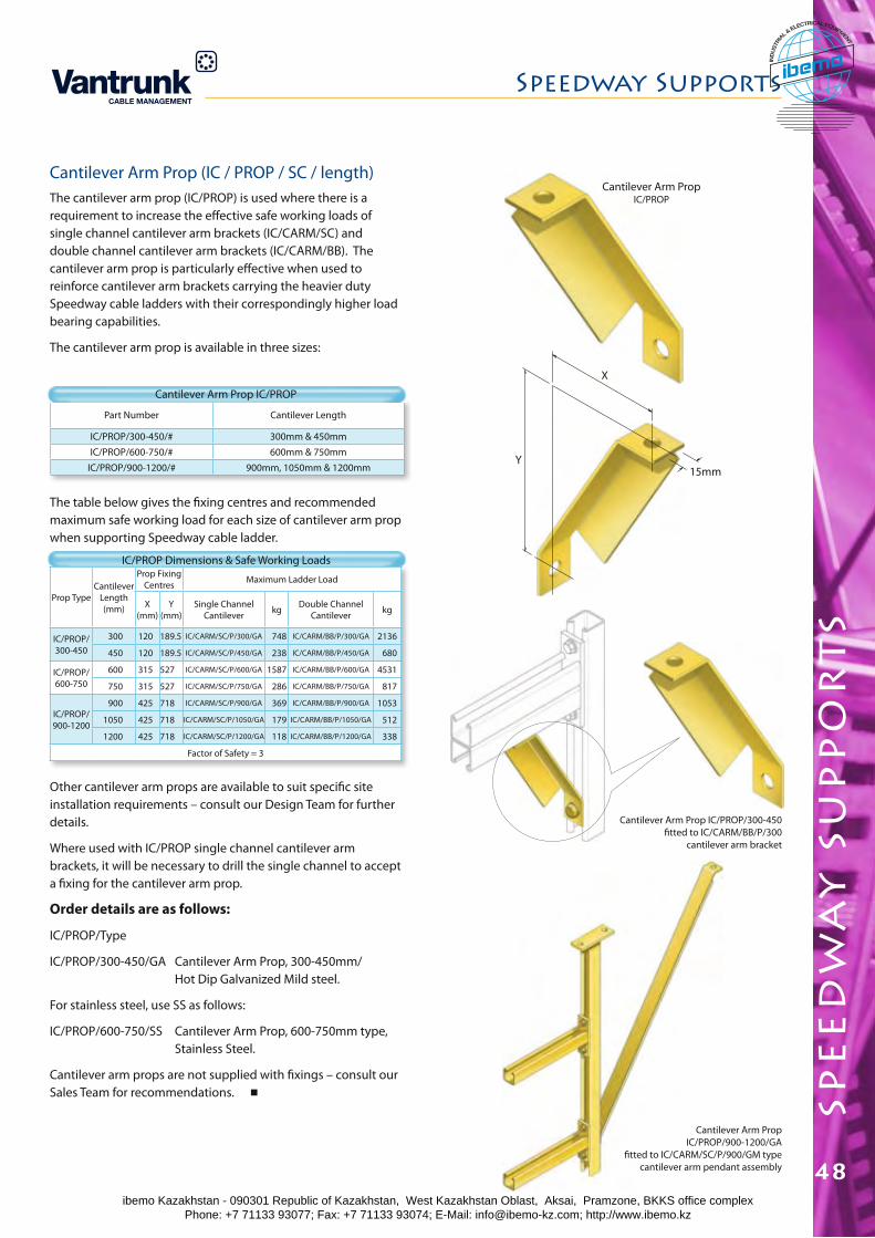
spe
ed
wa
y s
up
po
rt
s
Speedway Supports
48
Prop TypeCantilever
Length (mm)
Prop Fixing Centres Maximum Ladder Load
X (mm)
Y (mm)
Single Channel Cantilever kg Double Channel
Cantilever kg
IC/PROP/ 300-450
300 120 189.5 IC/CARM/SC/P/300/GA 748 IC/CARM/BB/P/300/GA 2136
450 120 189.5 IC/CARM/SC/P/450/GA 238 IC/CARM/BB/P/450/GA 680
IC/PROP/ 600-750
600 315 527 IC/CARM/SC/P/600/GA 1587 IC/CARM/BB/P/600/GA 4531
750 315 527 IC/CARM/SC/P/750/GA 286 IC/CARM/BB/P/750/GA 817
IC/PROP/ 900-1200
900 425 718 IC/CARM/SC/P/900/GA 369 IC/CARM/BB/P/900/GA 1053
1050 425 718 IC/CARM/SC/P/1050/GA 179 IC/CARM/BB/P/1050/GA 512
1200 425 718 IC/CARM/SC/P/1200/GA 118 IC/CARM/BB/P/1200/GA 338
Factor of Safety = 3
Cantilever Arm Prop (IC / PROP / SC / length)The cantilever arm prop (IC/PROP) is used where there is a requirement to increase the effective safe working loads of single channel cantilever arm brackets (IC/CARM/SC) and double channel cantilever arm brackets (IC/CARM/BB). The cantilever arm prop is particularly effective when used to reinforce cantilever arm brackets carrying the heavier duty Speedway cable ladders with their correspondingly higher load bearing capabilities.
The cantilever arm prop is available in three sizes:
Part Number Cantilever Length
IC/PROP/300-450/# 300mm & 450mm
IC/PROP/600-750/# 600mm & 750mm
IC/PROP/900-1200/# 900mm, 1050mm & 1200mm
The table below gives the fixing centres and recommended maximum safe working load for each size of cantilever arm prop when supporting Speedway cable ladder.
IC/PROP Dimensions & Safe Working Loads
Other cantilever arm props are available to suit specific site installation requirements – consult our Design Team for further details.
Where used with IC/PROP single channel cantilever arm brackets, it will be necessary to drill the single channel to accept a fixing for the cantilever arm prop.
Order details are as follows:
IC/PROP/Type
IC/PROP/300-450/GA Cantilever Arm Prop, 300-450mm/ Hot Dip Galvanized Mild steel.
For stainless steel, use SS as follows:
IC/PROP/600-750/SS Cantilever Arm Prop, 600-750mm type, Stainless Steel.
Cantilever arm props are not supplied with fixings – consult our Sales Team for recommendations.
Cantilever Arm PropIC/PROP
Cantilever Arm Prop IC/PROP/900-1200/GA
fitted to IC/CARM/SC/P/900/GM type cantilever arm pendant assembly
X
Y15mm
Cantilever Arm Prop IC/PROP/300-450 fitted to IC/CARM/BB/P/300
cantilever arm bracket
Cantilever Arm Prop IC/PROP
ibemo Kazakhstan - 090301 Republic of Kazakhstan, West Kazakhstan Oblast, Aksai, Pramzone, BKKS office complex Phone: +7 71133 93077; Fax: +7 71133 93074; E-Mail: [email protected]; http://www.ibemo.kz
ibemoIND
USTR
IA
L & ELECTRICAL EQUIPMENT
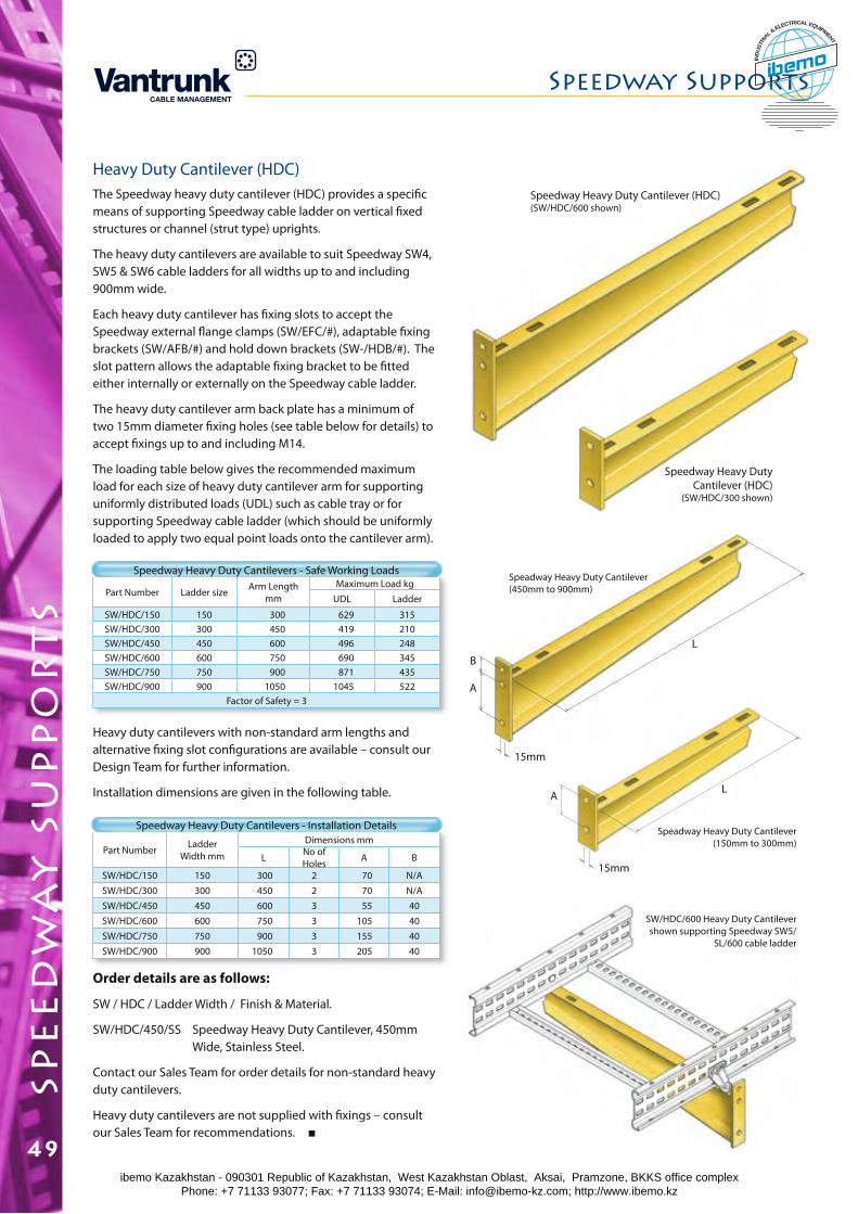
Heavy Duty Cantilever (HDC)The Speedway heavy duty cantilever (HDC) provides a specific means of supporting Speedway cable ladder on vertical fixed structures or channel (strut type) uprights.
The heavy duty cantilevers are available to suit Speedway SW4, SW5 & SW6 cable ladders for all widths up to and including 900mm wide.
Each heavy duty cantilever has fixing slots to accept the Speedway external flange clamps (SW/EFC/#), adaptable fixing brackets (SW/AFB/#) and hold down brackets (SW-/HDB/#). The slot pattern allows the adaptable fixing bracket to be fitted either internally or externally on the Speedway cable ladder.
The heavy duty cantilever arm back plate has a minimum of two 15mm diameter fixing holes (see table below for details) to accept fixings up to and including M14.
The loading table below gives the recommended maximum load for each size of heavy duty cantilever arm for supporting uniformly distributed loads (UDL) such as cable tray or for supporting Speedway cable ladder (which should be uniformly loaded to apply two equal point loads onto the cantilever arm).
Part Number Ladder size Arm Length mm
Maximum Load kgUDL Ladder
SW/HDC/150 150 300 629 315SW/HDC/300 300 450 419 210SW/HDC/450 450 600 496 248SW/HDC/600 600 750 690 345SW/HDC/750 750 900 871 435SW/HDC/900 900 1050 1045 522
Factor of Safety = 3
Speedway Heavy Duty Cantilevers - Safe Working Loads
Heavy duty cantilevers with non-standard arm lengths and alternative fixing slot configurations are available – consult our Design Team for further information.
Installation dimensions are given in the following table.
Part Number Ladder Width mm
Dimensions mm
L No of Holes A B
SW/HDC/150 150 300 2 70 N/ASW/HDC/300 300 450 2 70 N/ASW/HDC/450 450 600 3 55 40SW/HDC/600 600 750 3 105 40SW/HDC/750 750 900 3 155 40SW/HDC/900 900 1050 3 205 40
Speedway Heavy Duty Cantilevers - Installation Details
Order details are as follows:
SW / HDC / Ladder Width / Finish & Material.
SW/HDC/450/SS Speedway Heavy Duty Cantilever, 450mm Wide, Stainless Steel.
Contact our Sales Team for order details for non-standard heavy duty cantilevers.
Heavy duty cantilevers are not supplied with fixings – consult our Sales Team for recommendations.
Speedway Heavy Duty Cantilever (HDC)
(SW/HDC/300 shown)
Speedway Heavy Duty Cantilever (HDC)(SW/HDC/600 shown)
A
15mm
15mm
L
A
LB
SW/HDC/600 Heavy Duty Cantilever shown supporting Speedway SW5/
SL/600 cable ladder
Speadway Heavy Duty Cantilever (150mm to 300mm)
Speadway Heavy Duty Cantilever (450mm to 900mm)
spe
ed
wa
y s
up
po
rt
sSpeedway Supports
49ibemo Kazakhstan - 090301 Republic of Kazakhstan, West Kazakhstan Oblast, Aksai, Pramzone, BKKS office complex Phone: +7 71133 93077; Fax: +7 71133 93074; E-Mail: [email protected]; http://www.ibemo.kz
ibemoIND
USTR
IA
L & ELECTRICAL EQUIPMENT
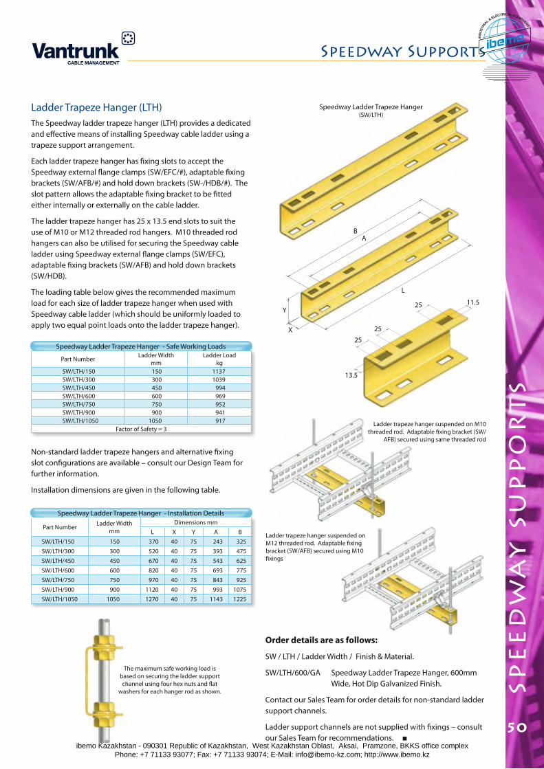
spe
ed
wa
y s
up
po
rt
s
Speedway Supports
50
Part Number Ladder Width mm
Dimensions mmL X Y A B
SW/LTH/150 150 370 40 75 243 325SW/LTH/300 300 520 40 75 393 475SW/LTH/450 450 670 40 75 543 625SW/LTH/600 600 820 40 75 693 775SW/LTH/750 750 970 40 75 843 925SW/LTH/900 900 1120 40 75 993 1075SW/LTH/1050 1050 1270 40 75 1143 1225
Part Number Ladder Widthmm
Ladder Loadkg
SW/LTH/150 150 1137SW/LTH/300 300 1039SW/LTH/450 450 994SW/LTH/600 600 969SW/LTH/750 750 952SW/LTH/900 900 941SW/LTH/1050 1050 917
Factor of Safety = 3
Ladder Trapeze Hanger (LTH)The Speedway ladder trapeze hanger (LTH) provides a dedicated and effective means of installing Speedway cable ladder using a trapeze support arrangement.
Each ladder trapeze hanger has fixing slots to accept the Speedway external flange clamps (SW/EFC/#), adaptable fixing brackets (SW/AFB/#) and hold down brackets (SW-/HDB/#). The slot pattern allows the adaptable fixing bracket to be fitted either internally or externally on the cable ladder.
The ladder trapeze hanger has 25 x 13.5 end slots to suit the use of M10 or M12 threaded rod hangers. M10 threaded rod hangers can also be utilised for securing the Speedway cable ladder using Speedway external flange clamps (SW/EFC), adaptable fixing brackets (SW/AFB) and hold down brackets (SW/HDB).
The loading table below gives the recommended maximum load for each size of ladder trapeze hanger when used with Speedway cable ladder (which should be uniformly loaded to apply two equal point loads onto the ladder trapeze hanger).
Speedway Ladder Trapeze Hanger - Safe Working Loads
Non-standard ladder trapeze hangers and alternative fixing slot configurations are available – consult our Design Team for further information.
Installation dimensions are given in the following table.
Speedway Ladder Trapeze Hanger - Installation Details
Order details are as follows:
SW / LTH / Ladder Width / Finish & Material.
SW/LTH/600/GA Speedway Ladder Trapeze Hanger, 600mm Wide, Hot Dip Galvanized Finish.
Contact our Sales Team for order details for non-standard ladder support channels.
Ladder support channels are not supplied with fixings – consult our Sales Team for recommendations.
Ladder trapeze hanger suspended on M12 threaded rod. Adaptable fixing bracket (SW/AFB) secured using M10 fixings
Ladder trapeze hanger suspended on M10 threaded rod. Adaptable fixing bracket (SW/
AFB) secured using same threaded rod
Speedway Ladder Trapeze Hanger(SW/LTH)
25
25
25 11.5
13.5
X
Y
AB
L
The maximum safe working load is based on securing the ladder support channel using four hex nuts and flat
washers for each hanger rod as shown.
ibemo Kazakhstan - 090301 Republic of Kazakhstan, West Kazakhstan Oblast, Aksai, Pramzone, BKKS office complex Phone: +7 71133 93077; Fax: +7 71133 93074; E-Mail: [email protected]; http://www.ibemo.kz
ibemoIND
USTR
IA
L & ELECTRICAL EQUIPMENT
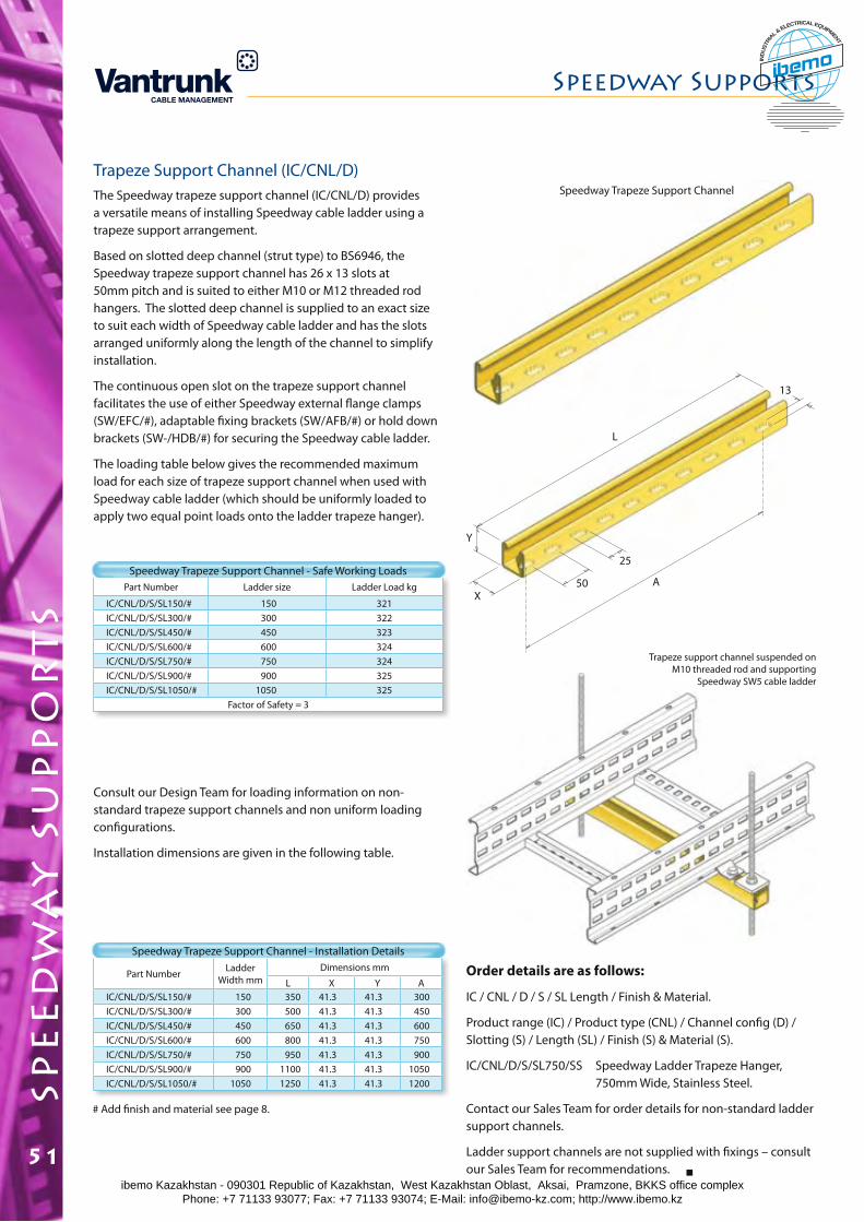
Part Number Ladder Width mm
Dimensions mm
L X Y AIC/CNL/D/S/SL150/# 150 350 41.3 41.3 300IC/CNL/D/S/SL300/# 300 500 41.3 41.3 450IC/CNL/D/S/SL450/# 450 650 41.3 41.3 600IC/CNL/D/S/SL600/# 600 800 41.3 41.3 750IC/CNL/D/S/SL750/# 750 950 41.3 41.3 900IC/CNL/D/S/SL900/# 900 1100 41.3 41.3 1050IC/CNL/D/S/SL1050/# 1050 1250 41.3 41.3 1200
Part Number Ladder size Ladder Load kg
IC/CNL/D/S/SL150/# 150 321IC/CNL/D/S/SL300/# 300 322IC/CNL/D/S/SL450/# 450 323IC/CNL/D/S/SL600/# 600 324IC/CNL/D/S/SL750/# 750 324IC/CNL/D/S/SL900/# 900 325IC/CNL/D/S/SL1050/# 1050 325
Factor of Safety = 3
Trapeze Support Channel (IC/CNL/D)The Speedway trapeze support channel (IC/CNL/D) provides a versatile means of installing Speedway cable ladder using a trapeze support arrangement.
Based on slotted deep channel (strut type) to BS6946, the Speedway trapeze support channel has 26 x 13 slots at 50mm pitch and is suited to either M10 or M12 threaded rod hangers. The slotted deep channel is supplied to an exact size to suit each width of Speedway cable ladder and has the slots arranged uniformly along the length of the channel to simplify installation.
The continuous open slot on the trapeze support channel facilitates the use of either Speedway external flange clamps (SW/EFC/#), adaptable fixing brackets (SW/AFB/#) or hold down brackets (SW-/HDB/#) for securing the Speedway cable ladder.
The loading table below gives the recommended maximum load for each size of trapeze support channel when used with Speedway cable ladder (which should be uniformly loaded to apply two equal point loads onto the ladder trapeze hanger).
Speedway Trapeze Support Channel - Safe Working Loads
Consult our Design Team for loading information on non-standard trapeze support channels and non uniform loading configurations.
Installation dimensions are given in the following table.
Order details are as follows:
IC / CNL / D / S / SL Length / Finish & Material.
Product range (IC) / Product type (CNL) / Channel config (D) / Slotting (S) / Length (SL) / Finish (S) & Material (S).
IC/CNL/D/S/SL750/SS Speedway Ladder Trapeze Hanger, 750mm Wide, Stainless Steel.
Contact our Sales Team for order details for non-standard ladder support channels.
Ladder support channels are not supplied with fixings – consult our Sales Team for recommendations.
Speedway Trapeze Support Channel - Installation Details
Trapeze support channel suspended on M10 threaded rod and supporting
Speedway SW5 cable ladder
Speedway Trapeze Support Channel
X
Y
50
25
A
13
L
Speedway Supportssp
ee
dw
ay
su
pp
or
ts
51
# Add finish and material see page 8.
ibemo Kazakhstan - 090301 Republic of Kazakhstan, West Kazakhstan Oblast, Aksai, Pramzone, BKKS office complex Phone: +7 71133 93077; Fax: +7 71133 93074; E-Mail: [email protected]; http://www.ibemo.kz
ibemoIND
USTR
IA
L & ELECTRICAL EQUIPMENT
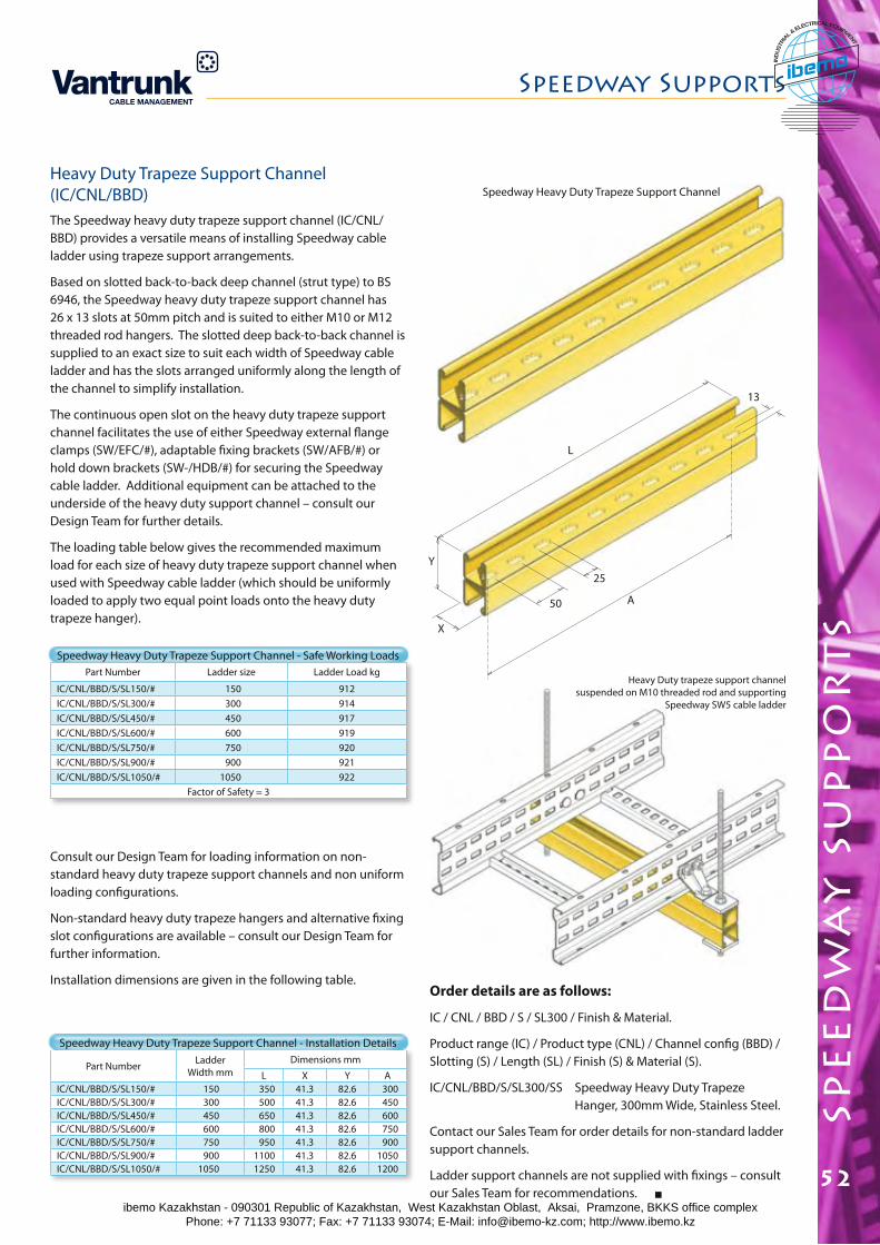
Speedway Supports
spe
ed
wa
y s
up
po
rt
s
52
Part Number Ladder Width mm
Dimensions mm
L X Y AIC/CNL/BBD/S/SL150/# 150 350 41.3 82.6 300IC/CNL/BBD/S/SL300/# 300 500 41.3 82.6 450IC/CNL/BBD/S/SL450/# 450 650 41.3 82.6 600IC/CNL/BBD/S/SL600/# 600 800 41.3 82.6 750IC/CNL/BBD/S/SL750/# 750 950 41.3 82.6 900IC/CNL/BBD/S/SL900/# 900 1100 41.3 82.6 1050IC/CNL/BBD/S/SL1050/# 1050 1250 41.3 82.6 1200
Part Number Ladder size Ladder Load kg
IC/CNL/BBD/S/SL150/# 150 912IC/CNL/BBD/S/SL300/# 300 914IC/CNL/BBD/S/SL450/# 450 917IC/CNL/BBD/S/SL600/# 600 919IC/CNL/BBD/S/SL750/# 750 920IC/CNL/BBD/S/SL900/# 900 921IC/CNL/BBD/S/SL1050/# 1050 922
Factor of Safety = 3
Heavy Duty Trapeze Support Channel (IC/CNL/BBD)The Speedway heavy duty trapeze support channel (IC/CNL/BBD) provides a versatile means of installing Speedway cable ladder using trapeze support arrangements.
Based on slotted back-to-back deep channel (strut type) to BS 6946, the Speedway heavy duty trapeze support channel has 26 x 13 slots at 50mm pitch and is suited to either M10 or M12 threaded rod hangers. The slotted deep back-to-back channel is supplied to an exact size to suit each width of Speedway cable ladder and has the slots arranged uniformly along the length of the channel to simplify installation.
The continuous open slot on the heavy duty trapeze support channel facilitates the use of either Speedway external flange clamps (SW/EFC/#), adaptable fixing brackets (SW/AFB/#) or hold down brackets (SW-/HDB/#) for securing the Speedway cable ladder. Additional equipment can be attached to the underside of the heavy duty support channel – consult our Design Team for further details.
The loading table below gives the recommended maximum load for each size of heavy duty trapeze support channel when used with Speedway cable ladder (which should be uniformly loaded to apply two equal point loads onto the heavy duty trapeze hanger).
Speedway Heavy Duty Trapeze Support Channel - Safe Working Loads
Consult our Design Team for loading information on non-standard heavy duty trapeze support channels and non uniform loading configurations.
Non-standard heavy duty trapeze hangers and alternative fixing slot configurations are available – consult our Design Team for further information.
Installation dimensions are given in the following table.Order details are as follows:
IC / CNL / BBD / S / SL300 / Finish & Material.
Product range (IC) / Product type (CNL) / Channel config (BBD) / Slotting (S) / Length (SL) / Finish (S) & Material (S).
IC/CNL/BBD/S/SL300/SS Speedway Heavy Duty Trapeze Hanger, 300mm Wide, Stainless Steel.
Contact our Sales Team for order details for non-standard ladder support channels.
Ladder support channels are not supplied with fixings – consult our Sales Team for recommendations.
Speedway Heavy Duty Trapeze Support Channel - Installation Details
Heavy Duty trapeze support channel suspended on M10 threaded rod and supporting
Speedway SW5 cable ladder
Speedway Heavy Duty Trapeze Support Channel
X
Y
50
25
A
13
L
ibemo Kazakhstan - 090301 Republic of Kazakhstan, West Kazakhstan Oblast, Aksai, Pramzone, BKKS office complex Phone: +7 71133 93077; Fax: +7 71133 93074; E-Mail: [email protected]; http://www.ibemo.kz
ibemoIND
USTR
IA
L & ELECTRICAL EQUIPMENT
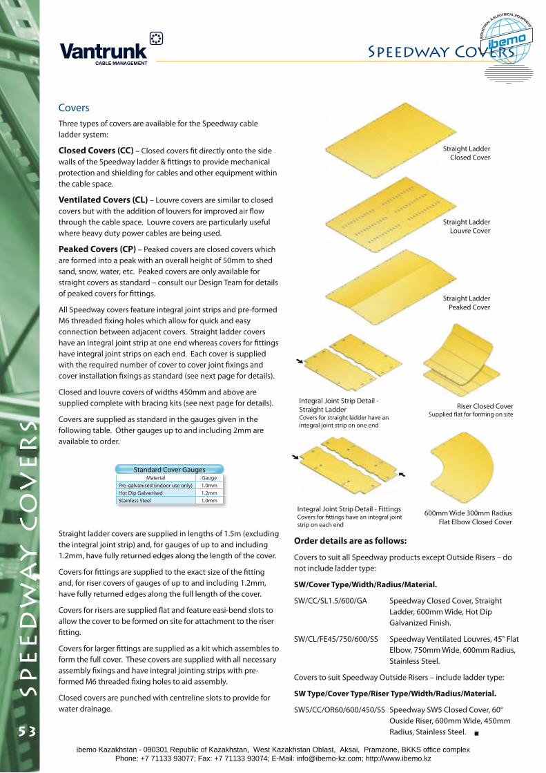
spe
ed
wa
y c
ov
er
s
CoversThree types of covers are available for the Speedway cable ladder system:
Closed Covers (CC) – Closed covers fit directly onto the side walls of the Speedway ladder & fittings to provide mechanical protection and shielding for cables and other equipment within the cable space.
Ventilated Covers (CL) – Louvre covers are similar to closed covers but with the addition of louvers for improved air flow through the cable space. Louvre covers are particularly useful where heavy duty power cables are being used.
Peaked Covers (CP) – Peaked covers are closed covers which are formed into a peak with an overall height of 50mm to shed sand, snow, water, etc. Peaked covers are only available for straight covers as standard – consult our Design Team for details of peaked covers for fittings.
All Speedway covers feature integral joint strips and pre-formed M6 threaded fixing holes which allow for quick and easy connection between adjacent covers. Straight ladder covers have an integral joint strip at one end whereas covers for fittings have integral joint strips on each end. Each cover is supplied with the required number of cover to cover joint fixings and cover installation fixings as standard (see next page for details).
Closed and louvre covers of widths 450mm and above are supplied complete with bracing kits (see next page for details).
Covers are supplied as standard in the gauges given in the following table. Other gauges up to and including 2mm are available to order.
Material GaugePre-galvanised (indoor use only) 1.0mmHot Dip Galvanised 1.2mmStainless Steel 1.0mm
Standard Cover Gauges
Straight ladder covers are supplied in lengths of 1.5m (excluding the integral joint strip) and, for gauges of up to and including 1.2mm, have fully returned edges along the length of the cover.
Covers for fittings are supplied to the exact size of the fitting and, for riser covers of gauges of up to and including 1.2mm, have fully returned edges along the full length of the cover.
Covers for risers are supplied flat and feature easi-bend slots to allow the cover to be formed on site for attachment to the riser fitting.
Covers for larger fittings are supplied as a kit which assembles to form the full cover. These covers are supplied with all necessary assembly fixings and have integral jointing strips with pre-formed M6 threaded fixing holes to aid assembly.
Closed covers are punched with centreline slots to provide for water drainage.
Riser Closed CoverSupplied flat for forming on site
Straight Ladder Closed Cover
Straight Ladder Louvre Cover
Straight Ladder Peaked Cover
Order details are as follows:
Covers to suit all Speedway products except Outside Risers – do not include ladder type:
SW/Cover Type/Width/Radius/Material.
SW/CC/SL1.5/600/GA Speedway Closed Cover, Straight Ladder, 600mm Wide, Hot Dip Galvanized Finish.
SW/CL/FE45/750/600/SS Speedway Ventilated Louvres, 45° Flat Elbow, 750mm Wide, 600mm Radius, Stainless Steel.
Covers to suit Speedway Outside Risers – include ladder type:
SW Type/Cover Type/Riser Type/Width/Radius/Material.
SW5/CC/OR60/600/450/SS Speedway SW5 Closed Cover, 60° Ouside Riser, 600mm Wide, 450mm Radius, Stainless Steel.
600mm Wide 300mm Radius Flat Elbow Closed Cover
Integral Joint Strip Detail - Straight LadderCovers for straight ladder have an integral joint strip on one end
Integral Joint Strip Detail - FittingsCovers for fittings have an integral joint strip on each end
Speedway Covers
53ibemo Kazakhstan - 090301 Republic of Kazakhstan, West Kazakhstan Oblast, Aksai, Pramzone, BKKS office complex Phone: +7 71133 93077; Fax: +7 71133 93074; E-Mail: [email protected]; http://www.ibemo.kz
ibemoIND
USTR
IA
L & ELECTRICAL EQUIPMENT
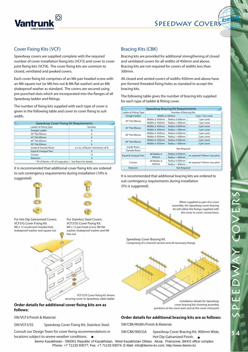
Speedway Covers
spe
ed
wa
y c
ov
er
s
54
Ladder & Fitting Type Number of Bracing KitsStraight ladder Widths ≥ 450mm 2 per 1.5m cover
30° Flat ElbowsWidths ≥ 450mm Radius ≤ 600mm 1 per coverWidths ≥ 450mm Radius > 600mm 1 per cover
45° Flat ElbowsWidths ≥ 450mm Radius ≤ 600mm 2 per coverWidths ≥ 450mm Radius > 600mm 2 per cover
60° Flat ElbowsWidths ≥ 450mm Radius ≤ 600mm 2 per coverWidths ≥ 450mm Radius > 600mm 2 per cover
90° Flat ElbowsWidths ≥ 450mm Radius ≤ 600mm 2 per coverWidths ≥ 450mm Radius > 600mm 3 per cover
Inside RisersNot Required
Outside Risers
Equal & Unequal Tees All Widths ≥ 450mm
Radius ≤ 600mmAs required 750mm max pitch
Radius > 600mm
Crosses All Widths ≥ 450mm
Radius ≤ 600mmAs required 750mm max pitch
Radius > 600mmReducers Not Required
Ladder & Fitting Type NumberStraight Ladder 830° Flat Elbows 645° Flat Elbows 660° Flat Elbows 690° Flat Elbows 6Inside & Outside Risers 2 x no. of facets* (minimum of 4)Equal & Unequal Tees 9Crosses 12Reducers 4
* Nº of facets = Nº of rungs plus 1. See Risers for details.
Cover Fixing Kits (VCF)Speedway covers are supplied complete with the required number of cover installation fixing kits (VCF3) and cover to cover joint fixing kits (VCF8). The cover fixing kits are common to closed, ventilated and peaked covers.
Each cover fixing kit comprises of an M6 pan headed screw with an M6 square nut (or M6 hex nut & M6 flat washer) and an M6 shakeproof washer as standard. The covers are secured using pre-punched slots which are incorporated into the flanges of all Speedway ladder and fittings.
The number of fixing kits supplied with each type of cover is given in the following table and cover to cover fixing to suit width.
Speedway Cover Fixing Kit Requirements
It is recommended that additional cover fixing kits are ordered to suit contingency requirements during installation (10% is suggested).
Speedway Bracing Kit Requirements
It is recommended that additional bracing kits are ordered to suit contingency requirements during installation (5% is suggested).
Order details for additional cover fixing kits are as follows:
SW/VCF3/Finish & Material.
SW/VCF3/SS Speedway Cover Fixing Kit, Stainless Steel.
Order details for additional bracing kits are as follows:
SW/CBK/Width/Finish & Material.
SW/CBK/900/GA Speedway Cover Bracing Kit, 900mm Wide, Hot Dip Galvanized Finish.
For Stainless Steel Covers:VCF3/SS Cover Fixing KitM6 x 12 pan head screw, M6 flat washer, shakeproof washer and M6 hex nut
For Hot Dip Galvanised Covers:VCF3/G Cover Fixing KitM6 x 12 mushroom headed bolt, shakeproof washer and square nut
VCF3/SS Cover fixing kit shown securing cover to Speedway cable ladder
Consult our Design Team for cover fixing recommendations in locations subject to severe weather conditions.
Installation details for Speedway cover bracing kits showing assembly
positions at the cover joint and at the cover mid point
Speedway Cover Bracing KitComprising of a channel section and all necessary fixings
When supplied as part of a cover assembly, the Speedway cover bracing kit will utilise the fixings supplied with
the cover to cover connections.
Bracing Kits (CBK)Bracing kits are provided for additional strengthening of closed and ventilated covers for all widths of 450mm and above. Bracing kits are not required for covers of widths less than 300mm.
All closed and vented covers of widths 450mm and above have pre-formed threaded fixing holes as standard to accept the bracing kits.
The following table gives the number of bracing kits supplied for each type of ladder & fitting cover.
ibemo Kazakhstan - 090301 Republic of Kazakhstan, West Kazakhstan Oblast, Aksai, Pramzone, BKKS office complex Phone: +7 71133 93077; Fax: +7 71133 93074; E-Mail: [email protected]; http://www.ibemo.kz
ibemoIND
USTR
IA
L & ELECTRICAL EQUIPMENT
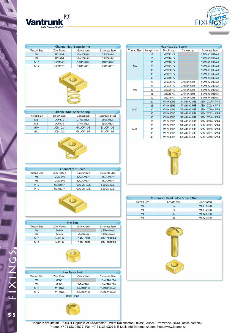
fix
ing
sFixings
55
Thread Size Zinc Plated Galvanized Stainless SteelM6 UCM6/N GAUCM6/N SSUCM6/NM8 UCM8/N GAUCM8/N SSUCM8/N
M10 UCM10/N GAUCM10/N SSUCM10/NM12 UCM12/N GAUCM12/N SSUCM12/N
Thread Size Zinc Plated Galvanized Stainless SteelM6 UCM6/S GAUCM6/S SSUCM6/SM8 UCM8/S GAUCM8/S SSUCM8/S
M10 UCM10/S GAUCM10/S SSUCM10/SM12 UCM12/S GAUCM12/S SSUCM12/S
Thread Size Zinc Plated Galvanized Stainless SteelM6 UCM6/L GAUCM6/L SSUCM6/LM8 UCM8/L GAUCM8/L SSUCM8/L
M10 UCM10/L GAUCM10/L SSUCM10/LM12 UCM12/L GAUCM12/L SSUCM12/L
Channel Nut - Long Spring
Channel Nut - Short Spring
Channel Nut - Plain
Thread Size Length mm Zinc Plated Galvanized Stainless Steel
M6
12 M6X12HS SSM6X12HS/A416 M6X16HS SSM6X16HS/A420 M6X20HS SSM6X20HS/A425 M6X25HS SSM6X25HS/A430 M6X30HS SSM6X30HS/A435 M6X35HS SSM6X35HS/A440 M6X40HS SSM6X40HS/A4
M8
20 M8X20HS GAM8X20HS SSM8X20HS/A425 M8X25HS GAM8X25HS SSM8X25HS/A430 M8X30HS GAM8X30HS SSM8X30HS/A435 M8X35HS GAM8X35HS SSM8X35HS/A440 M8X40HS GAM8X40HS SSM8X40HS/A4
M10
20 M10X20HS GAM10X20HS SSM10X20HS/A425 M10X25HS GAM10X25HS SSM10X25HS/A430 M10X30HS GAM10X30HS SSM10X30HS/A435 M10X35HS GAM10X35HS SSM10X35HS/A440 M10X40HS GAM10X40HS SSM10X40HS/A4
M12
20 M12X20HS GAM12X20HS SSM12X20HS/A425 M12X25HS GAM12X25HS SSM12X25HS/A430 M12X30HS GAM12X30HS SSM12X30HS/A435 M12X35HS GAM12X35HS SSM12X35HS/A440 M12X40HS GAM12X40HS SSM12X40HS/A4
Hex Head Set Screw
Thread Size Zinc Plated Galvanized Stainless SteelM6 M6HN SSM6HN/A4M8 M8HN GAM8HN SSM8HN/A4
M10 M10HN GAM10HN SSM10HN/A4M12 M12HN GAM12HN SSM12HN/A4
Hex Nut
Thread Size Zinc Plated Galvanized Stainless SteelM6 M6NYL SSM6NYL/A4M8 M8NYL GAM8NYL SSM8NYL/A4
M10 M10NYL GAM10NYL SSM10NYL/A4M12 M12NYL GAM12NYL SSM12NYL/A4
Delta Finish
Hex Nyloc Nut
Thread Size Length mm Zinc PlatedM6 12 M6X12RNBM6 16 M6X16RNBM6 20 M6X20RNBM6 25 M6X25RNB
Mushroom Head Bolt & Square Nut
ibemo Kazakhstan - 090301 Republic of Kazakhstan, West Kazakhstan Oblast, Aksai, Pramzone, BKKS office complex Phone: +7 71133 93077; Fax: +7 71133 93074; E-Mail: [email protected]; http://www.ibemo.kz
ibemoIND
USTR
IA
L & ELECTRICAL EQUIPMENT
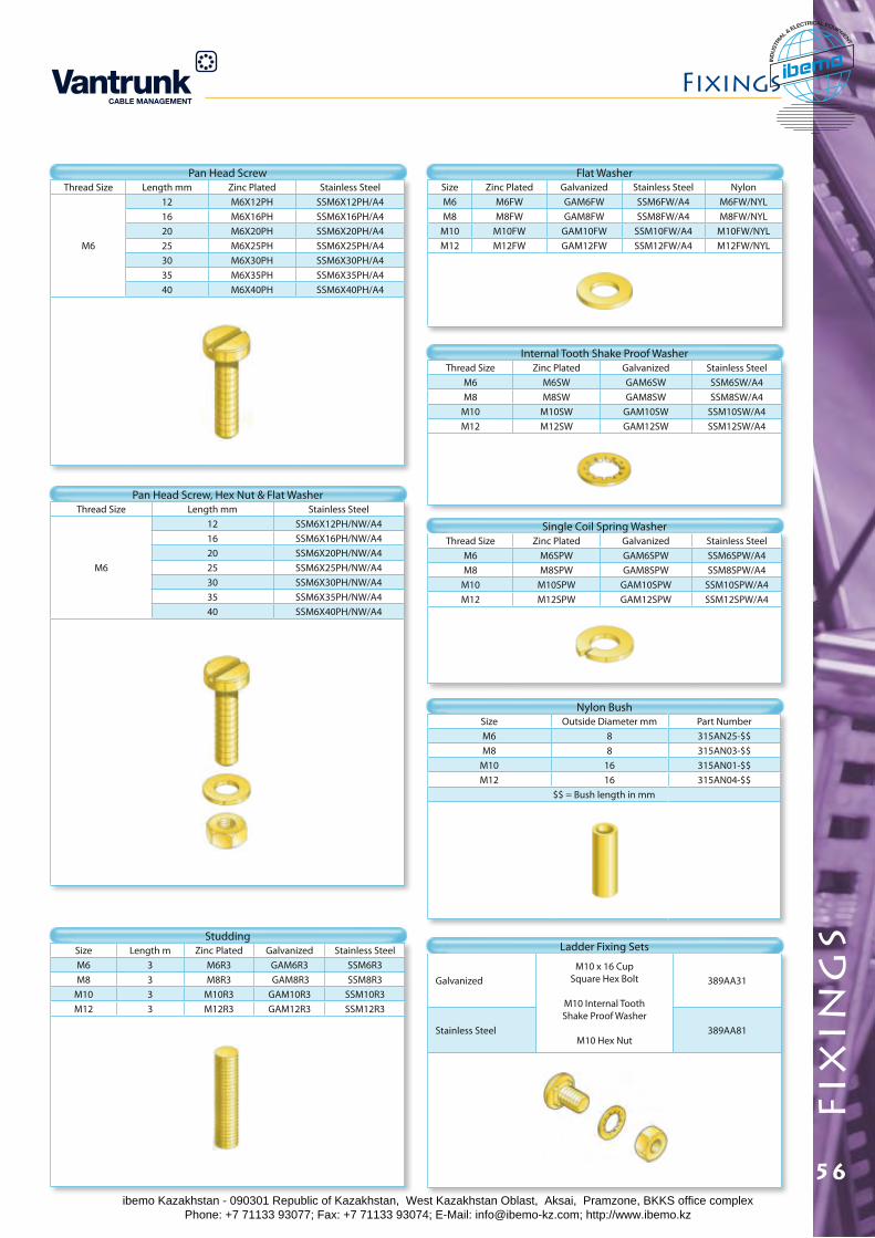
Fixings
fix
ing
s
56
Size Zinc Plated Galvanized Stainless Steel NylonM6 M6FW GAM6FW SSM6FW/A4 M6FW/NYLM8 M8FW GAM8FW SSM8FW/A4 M8FW/NYL
M10 M10FW GAM10FW SSM10FW/A4 M10FW/NYLM12 M12FW GAM12FW SSM12FW/A4 M12FW/NYL
Thread Size Zinc Plated Galvanized Stainless SteelM6 M6SW GAM6SW SSM6SW/A4M8 M8SW GAM8SW SSM8SW/A4
M10 M10SW GAM10SW SSM10SW/A4M12 M12SW GAM12SW SSM12SW/A4
Thread Size Zinc Plated Galvanized Stainless SteelM6 M6SPW GAM6SPW SSM6SPW/A4M8 M8SPW GAM8SPW SSM8SPW/A4
M10 M10SPW GAM10SPW SSM10SPW/A4M12 M12SPW GAM12SPW SSM12SPW/A4
GalvanizedM10 x 16 Cup
Square Hex Bolt
M10 Internal Tooth Shake Proof Washer
M10 Hex Nut
389AA31
Stainless Steel 389AA81
Size Outside Diameter mm Part Number M6 8 315AN25-$$M8 8 315AN03-$$
M10 16 315AN01-$$M12 16 315AN04-$$
$$ = Bush length in mm
Thread Size Length mm Zinc Plated Stainless Steel
M6
12 M6X12PH SSM6X12PH/A416 M6X16PH SSM6X16PH/A420 M6X20PH SSM6X20PH/A425 M6X25PH SSM6X25PH/A430 M6X30PH SSM6X30PH/A435 M6X35PH SSM6X35PH/A440 M6X40PH SSM6X40PH/A4
Internal Tooth Shake Proof Washer
Single Coil Spring Washer
Pan Head Screw
Thread Size Length mm Stainless Steel
M6
12 SSM6X12PH/NW/A416 SSM6X16PH/NW/A420 SSM6X20PH/NW/A425 SSM6X25PH/NW/A430 SSM6X30PH/NW/A435 SSM6X35PH/NW/A440 SSM6X40PH/NW/A4
Pan Head Screw, Hex Nut & Flat Washer
Flat Washer
Size Length m Zinc Plated Galvanized Stainless SteelM6 3 M6R3 GAM6R3 SSM6R3M8 3 M8R3 GAM8R3 SSM8R3
M10 3 M10R3 GAM10R3 SSM10R3M12 3 M12R3 GAM12R3 SSM12R3
Studding
Nylon Bush
Ladder Fixing Sets
ibemo Kazakhstan - 090301 Republic of Kazakhstan, West Kazakhstan Oblast, Aksai, Pramzone, BKKS office complex Phone: +7 71133 93077; Fax: +7 71133 93074; E-Mail: [email protected]; http://www.ibemo.kz
ibemoIND
USTR
IA
L & ELECTRICAL EQUIPMENT
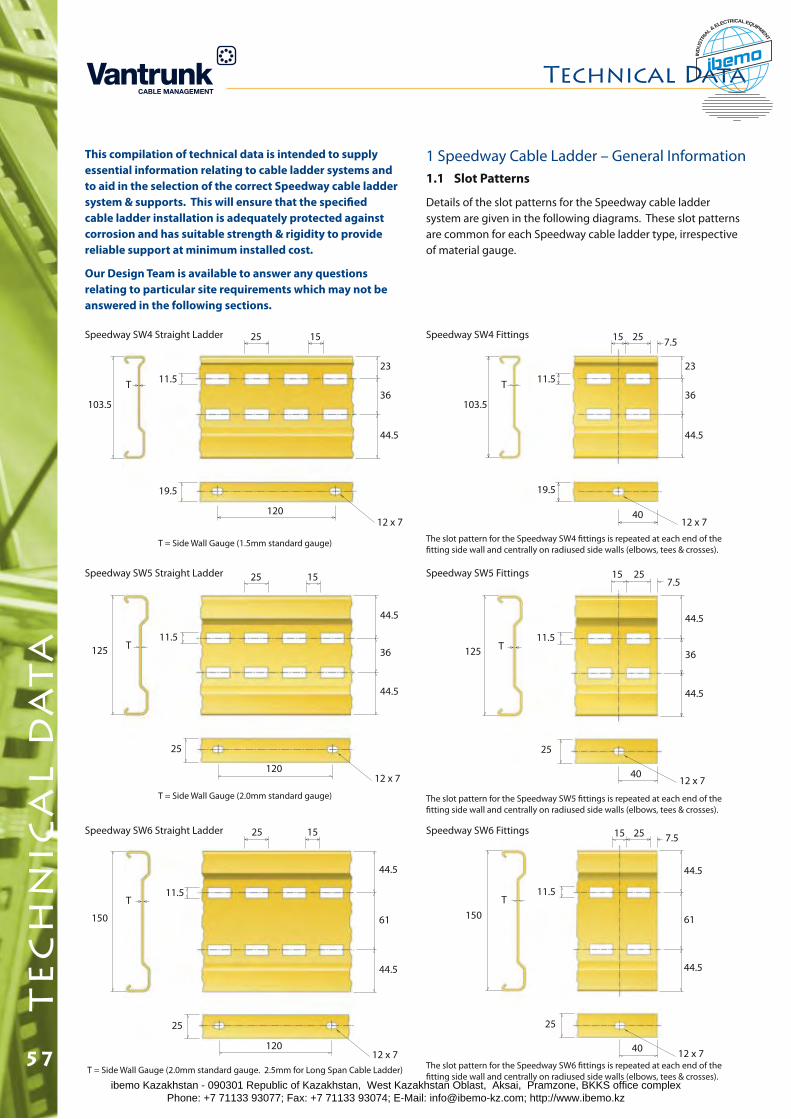
te
ch
nic
al
da
ta
This compilation of technical data is intended to supply essential information relating to cable ladder systems and to aid in the selection of the correct Speedway cable ladder system & supports. This will ensure that the specified cable ladder installation is adequately protected against corrosion and has suitable strength & rigidity to provide reliable support at minimum installed cost.
Our Design Team is available to answer any questions relating to particular site requirements which may not be answered in the following sections.
Speedway SW4 Straight Ladder Speedway SW4 Fittings
T = Side Wall Gauge (1.5mm standard gauge) The slot pattern for the Speedway SW4 fittings is repeated at each end of the fitting side wall and centrally on radiused side walls (elbows, tees & crosses).
1 Speedway Cable Ladder – General Information1.1 Slot Patterns
Details of the slot patterns for the Speedway cable ladder system are given in the following diagrams. These slot patterns are common for each Speedway cable ladder type, irrespective of material gauge.
103.5
T 11.5
25 15
23
36
44.5
120
19.5
12 x 740
12 x 7
103.5
T 11.523
36
44.5
19.5
25 7.515
Speedway SW5 Straight Ladder Speedway SW5 Fittings
T = Side Wall Gauge (2.0mm standard gauge) The slot pattern for the Speedway SW5 fittings is repeated at each end of the fitting side wall and centrally on radiused side walls (elbows, tees & crosses).
125 T11.5
25 15
44.5
36
44.5
120
25
12 x 7 4012 x 7
125 T11.5
25
257.5
15
Speedway SW6 Straight Ladder Speedway SW6 Fittings
T = Side Wall Gauge (2.0mm standard gauge. 2.5mm for Long Span Cable Ladder) The slot pattern for the Speedway SW6 fittings is repeated at each end of the fitting side wall and centrally on radiused side walls (elbows, tees & crosses).
150
T11.5
25 15
44.5
61
44.5
120
25
12 x 740 12 x 7
150T
11.5
25
25 7.515
44.5
36
44.5
44.5
61
44.5
Technical Data
57ibemo Kazakhstan - 090301 Republic of Kazakhstan, West Kazakhstan Oblast, Aksai, Pramzone, BKKS office complex Phone: +7 71133 93077; Fax: +7 71133 93074; E-Mail: [email protected]; http://www.ibemo.kz
ibemoIND
USTR
IA
L & ELECTRICAL EQUIPMENT
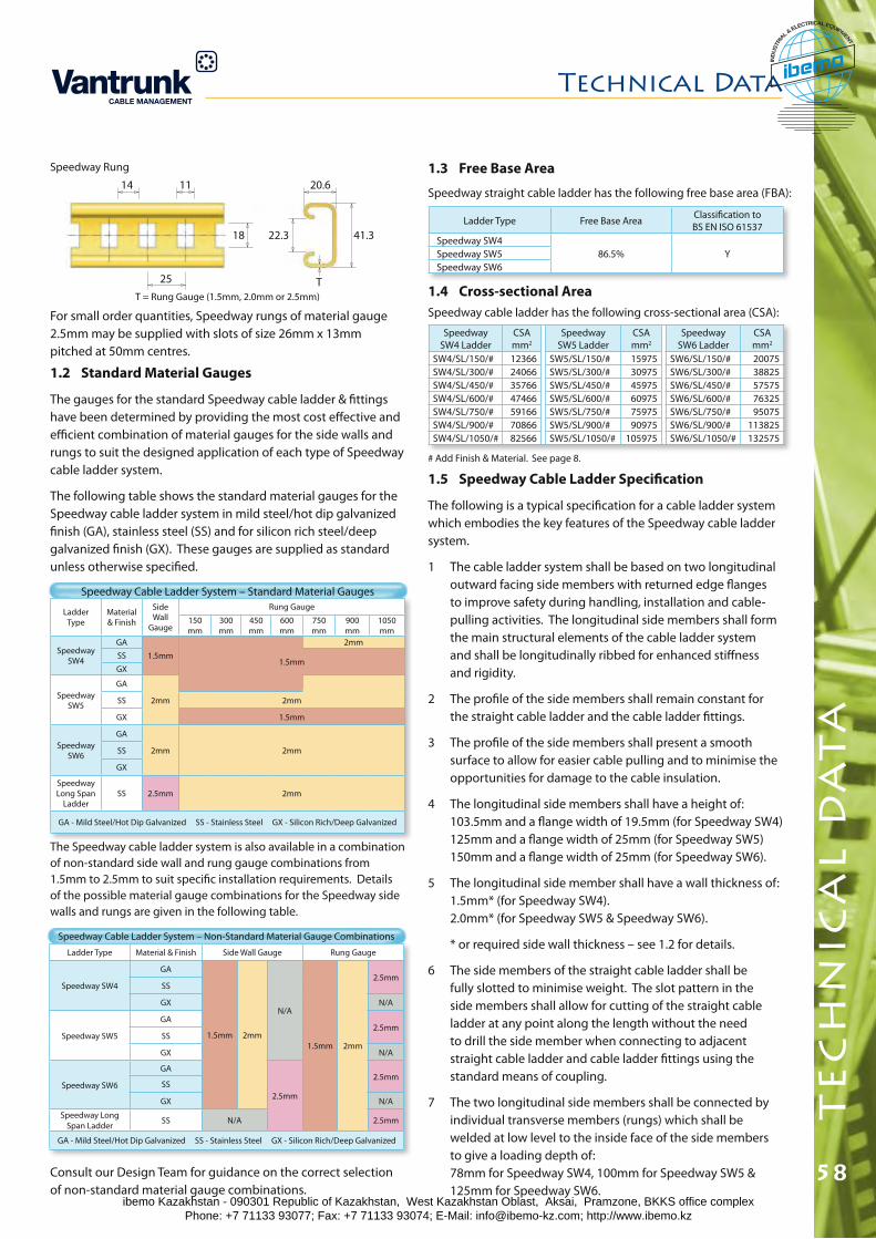
Technical Data
te
ch
nic
al
da
ta
58
1.4 Cross-sectional AreaSpeedway cable ladder has the following cross-sectional area (CSA):
1.3 Free Base Area
Speedway straight cable ladder has the following free base area (FBA):
Ladder Type Free Base Area Classification to BS EN ISO 61537
Speedway SW486.5% YSpeedway SW5
Speedway SW6
Speedway SW4 Ladder
CSAmm2
SpeedwaySW5 Ladder
CSAmm2
SpeedwaySW6 Ladder
CSAmm2
SW4/SL/150/# 12366 SW5/SL/150/# 15975 SW6/SL/150/# 20075SW4/SL/300/# 24066 SW5/SL/300/# 30975 SW6/SL/300/# 38825SW4/SL/450/# 35766 SW5/SL/450/# 45975 SW6/SL/450/# 57575SW4/SL/600/# 47466 SW5/SL/600/# 60975 SW6/SL/600/# 76325SW4/SL/750/# 59166 SW5/SL/750/# 75975 SW6/SL/750/# 95075SW4/SL/900/# 70866 SW5/SL/900/# 90975 SW6/SL/900/# 113825SW4/SL/1050/# 82566 SW5/SL/1050/# 105975 SW6/SL/1050/# 132575
Ladder Type
Material & Finish
Side Wall
Gauge
Rung Gauge
150mm
300mm
450mm
600mm
750mm
900mm
1050mm
Speedway SW4
GA
1.5mm
2mm
SS1.5mm
GX
Speedway SW5
GA
2mmSS 2mm
GX 1.5mm
Speedway SW6
GA
2mm 2mmSS
GX
Speedway Long Span
LadderSS 2.5mm 2mm
GA - Mild Steel/Hot Dip Galvanized SS - Stainless Steel GX - Silicon Rich/Deep Galvanized
For small order quantities, Speedway rungs of material gauge 2.5mm may be supplied with slots of size 26mm x 13mm pitched at 50mm centres.
T = Rung Gauge (1.5mm, 2.0mm or 2.5mm)
14 11
25
18 22.3
20.6
41.3
T
1.2 Standard Material Gauges
The gauges for the standard Speedway cable ladder & fittings have been determined by providing the most cost effective and efficient combination of material gauges for the side walls and rungs to suit the designed application of each type of Speedway cable ladder system.
The following table shows the standard material gauges for the Speedway cable ladder system in mild steel/hot dip galvanized finish (GA), stainless steel (SS) and for silicon rich steel/deep galvanized finish (GX). These gauges are supplied as standard unless otherwise specified.
Speedway Cable Ladder System – Standard Material Gauges
The Speedway cable ladder system is also available in a combination of non-standard side wall and rung gauge combinations from 1.5mm to 2.5mm to suit specific installation requirements. Details of the possible material gauge combinations for the Speedway side walls and rungs are given in the following table.
Ladder Type Material & Finish Side Wall Gauge Rung Gauge
Speedway SW4
GA
1.5mm 2mm
N/A
1.5mm 2mm
2.5mmSS
GX N/A
Speedway SW5
GA2.5mm
SS
GX N/A
Speedway SW6
GA
2.5mm
2.5mmSS
GX N/A
Speedway Long Span Ladder SS N/A 2.5mm
GA - Mild Steel/Hot Dip Galvanized SS - Stainless Steel GX - Silicon Rich/Deep Galvanized
Consult our Design Team for guidance on the correct selection of non-standard material gauge combinations.
Speedway Cable Ladder System – Non-Standard Material Gauge Combinations
1.5 Speedway Cable Ladder Specification
The following is a typical specification for a cable ladder system which embodies the key features of the Speedway cable ladder system.
1 The cable ladder system shall be based on two longitudinal outward facing side members with returned edge flanges to improve safety during handling, installation and cable- pulling activities. The longitudinal side members shall form the main structural elements of the cable ladder system and shall be longitudinally ribbed for enhanced stiffness and rigidity.
2 The profile of the side members shall remain constant for the straight cable ladder and the cable ladder fittings.
3 The profile of the side members shall present a smooth surface to allow for easier cable pulling and to minimise the opportunities for damage to the cable insulation.
4 The longitudinal side members shall have a height of: 103.5mm and a flange width of 19.5mm (for Speedway SW4) 125mm and a flange width of 25mm (for Speedway SW5) 150mm and a flange width of 25mm (for Speedway SW6).
5 The longitudinal side member shall have a wall thickness of: 1.5mm* (for Speedway SW4). 2.0mm* (for Speedway SW5 & Speedway SW6).
* or required side wall thickness – see 1.2 for details.
6 The side members of the straight cable ladder shall be fully slotted to minimise weight. The slot pattern in the side members shall allow for cutting of the straight cable ladder at any point along the length without the need to drill the side member when connecting to adjacent straight cable ladder and cable ladder fittings using the standard means of coupling.
7 The two longitudinal side members shall be connected by individual transverse members (rungs) which shall be welded at low level to the inside face of the side members to give a loading depth of: 78mm for Speedway SW4, 100mm for Speedway SW5 & 125mm for Speedway SW6.
Speedway Rung
# Add Finish & Material. See page 8.
ibemo Kazakhstan - 090301 Republic of Kazakhstan, West Kazakhstan Oblast, Aksai, Pramzone, BKKS office complex Phone: +7 71133 93077; Fax: +7 71133 93074; E-Mail: [email protected]; http://www.ibemo.kz
ibemoIND
USTR
IA
L & ELECTRICAL EQUIPMENT

8 The transverse members shall be evenly spaced at 300mm centres along the length of the straight cable ladder. The transverse members for horizontal bends (flat elbows) shall be located at either 0° or 7.5° and multiples thereof around the fitting subject to a maximum spacing of 465mm between adjacent transverse members when measured as a linear distance along the outside face of the horizontal bend. The transverse members for horizontal intersection fittings (tees and crosses) shall be evenly spaced at intervals not exceeding 465mm. The transverse members for vertical bends (inside and outside risers) shall be evenly spaced at intervals not exceeding 300mm centres.
9 The transverse members shall be of channel profile with a width of 41.3mm and a height of 20.6mm. The transverse members shall have a continuous open slot to suit the mounting of cable restraint devices (cleats, etc.) and other equipment using standard channel nuts and fixings. The base of the transverse members shall have slots of size 18mm x 11mm at 25mm centres to suit the use of cable ties and banding.
10 The transverse members shall have a wall thickness of:
Hot Dip Galvanised Finish;
1.5mm* for widths up to and including 600mm, and a wall thickness of 2.0mm* for widths above 600mm (for Speedway SW4)
1.5mm* for widths up to and including 600mm, and a wall thickness of 2.0mm* for widths above 600mm (for Speedway SW5)
2.0mm* (for Speedway SW6)
Stainless Steel;
1.5mm* (for Speedway SW4)
2.0mm* (for Speedway SW5)
2.0mm* (for Speedway SW6)
Deep Galvanised Finish;
1.5mm* (for Speedway SW4)
1.5mm* (for Speedway SW5)
2.0mm* (for Speedway SW6)
* or required rung wall thickness – see 1.2 for details.
11 The transverse members for straight cable ladder shall be orientated with the continuous slot facing alternately upwards and downwards. The transverse members for cable ladder fittings shall be orientated with the continuous slot facing upwards to allow for the securing of cable restraint devices (cleats, etc.) at every rung position.
12 The width of the straight cable ladder and the cable ladder fittings shall be measured relative to the inside faces of the side members. The widths of the straight cable ladder and cable ladder fittings shall be 150mm, 300mm, 450mm, 600mm, 750mm, 900mm & 1050mm.
13 The straight cable ladder shall have a length of 3000mm or 6000mm as specified.
14 The cable ladder fittings shall have fixed angles of 90°, 60°, 45° and 30°.
15 Radiused cable ladder fittings shall have a radius of 300mm, 450mm, 600mm, 750mm, 900mm, 1050mm & 1200mm. The radius of the fitting shall be measured relative to the inside face on the radiused side wall.
16 The cable ladder system shall be manufactured using:
For Mild Steel – Hot Dip Galvanized Finish; mild steel of grade D11 to BS EN 10111 and shall be hot dip galvanized after manufacture to BS EN ISO 1461.
For Stainless Steel (Marine Grade); using stainless steel material 1.4404 (316 marine grade) to BS EN 10088.
For Silicon-rich Steel – Deep Galvanized Finish; silicon-rich steel (generally complying to grade S355 to BS EN 10025) and shall be deep galvanized after manufacture to twice the coating thickness specified by BS EN ISO 1461.
17 The couplers shall be profiled to match the profile of the cable ladder. The couplers shall be secured using M10 square-shouldered bolts with rounded heads. The bolts shall be secured with M10 hex nuts and M10 shake-proof washers as standard. The couplers shall have a slot pattern which prevents slip between adjacent straight ladder lengths (including cut lengths of straight cable ladder) and between cable ladder fittings. The couplers shall have a slot pattern which allows for easy connection to cut lengths of straight cable ladder without the need for on- site drilling.
2 Installation Recommendations2.1 Loads
A correctly designed and specified cable ladder installation should take into account the nature and extent of the loads which will be imposed on the cable ladder system. These loads comprise of dead loads including the self-weight of the cable ladder system, the weight of the cables and secondary equipment attached to the cable ladder, imposed loads which occur during installation of the cable ladder system and during cable pulling operations, and external loads such as wind, snow, & ice.
Cable ladders are often employed in locations where the wind speeds may cause considerable lateral loading and careful consideration must be given to design to ensure a satisfactory installation. An awareness of the worst possible climate conditions is necessary when specifying the correct Speedway cable ladder system.
The load-deflection information given in 3.4 is based on static loading of the Speedway cable ladder installation and does not take into account dynamic effects such as earthquake loading, etc.
Technical Datat
ec
hn
ica
l d
at
a
59ibemo Kazakhstan - 090301 Republic of Kazakhstan, West Kazakhstan Oblast, Aksai, Pramzone, BKKS office complex Phone: +7 71133 93077; Fax: +7 71133 93074; E-Mail: [email protected]; http://www.ibemo.kz
ibemoIND
USTR
IA
L & ELECTRICAL EQUIPMENT
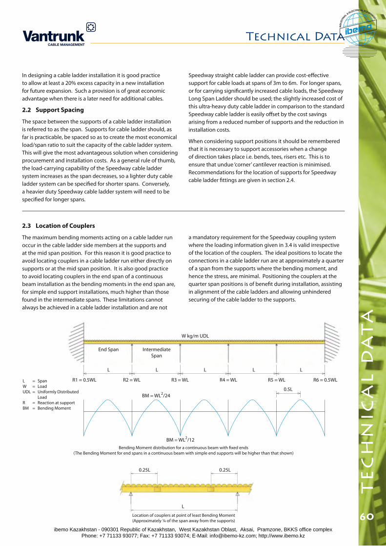
Technical Data
60
te
ch
nic
al
da
ta
In designing a cable ladder installation it is good practice to allow at least a 20% excess capacity in a new installation for future expansion. Such a provision is of great economic advantage when there is a later need for additional cables.
2.2 Support Spacing
The space between the supports of a cable ladder installation is referred to as the span. Supports for cable ladder should, as far is practicable, be spaced so as to create the most economical load/span ratio to suit the capacity of the cable ladder system. This will give the most advantageous solution when considering procurement and installation costs. As a general rule of thumb, the load-carrying capability of the Speedway cable ladder system increases as the span decreases, so a lighter duty cable ladder system can be specified for shorter spans. Conversely, a heavier duty Speedway cable ladder system will need to be specified for longer spans.
2.3 Location of Couplers
The maximum bending moments acting on a cable ladder run occur in the cable ladder side members at the supports and at the mid span position. For this reason it is good practice to avoid locating couplers in a cable ladder run either directly on supports or at the mid span position. It is also good practice to avoid locating couplers in the end span of a continuous beam installation as the bending moments in the end span are, for simple end support installations, much higher than those found in the intermediate spans. These limitations cannot always be achieved in a cable ladder installation and are not
0.25L 0.25L
L
W kg/m UDL
End Span
R1 = 0.5WL
L L L L L
IntermediateSpan
R2 = WL R3 = WL R4 = WL R5 = WL R6 = 0.5WL
BM = WL2/24
BM = WL2/12Bending Moment distribution for a continuous beam with fixed ends
(The Bending Moment for end spans in a continuous beam with simple end supports will be higher than that shown)
0.5L
L = SpanW = LoadUDL = Uniformly Distributed LoadR = Reaction at supportBM = Bending Moment
Location of couplers at point of least Bending Moment(Approximately ¼ of the span away from the supports)
a mandatory requirement for the Speedway coupling system where the loading information given in 3.4 is valid irrespective of the location of the couplers. The ideal positions to locate the connections in a cable ladder run are at approximately a quarter of a span from the supports where the bending moment, and hence the stress, are minimal. Positioning the couplers at the quarter span positions is of benefit during installation, assisting in alignment of the cable ladders and allowing unhindered securing of the cable ladder to the supports.
Speedway straight cable ladder can provide cost-effective support for cable loads at spans of 3m to 6m. For longer spans, or for carrying significantly increased cable loads, the Speedway Long Span Ladder should be used; the slightly increased cost of this ultra-heavy duty cable ladder in comparison to the standard Speedway cable ladder is easily offset by the cost savings arising from a reduced number of supports and the reduction in installation costs.
When considering support positions it should be remembered that it is necessary to support accessories when a change of direction takes place i.e. bends, tees, risers etc. This is to ensure that undue ‘corner’ cantilever reaction is minimised. Recommendations for the location of supports for Speedway cable ladder fittings are given in section 2.4.
ibemo Kazakhstan - 090301 Republic of Kazakhstan, West Kazakhstan Oblast, Aksai, Pramzone, BKKS office complex Phone: +7 71133 93077; Fax: +7 71133 93074; E-Mail: [email protected]; http://www.ibemo.kz
ibemoIND
USTR
IA
L & ELECTRICAL EQUIPMENT
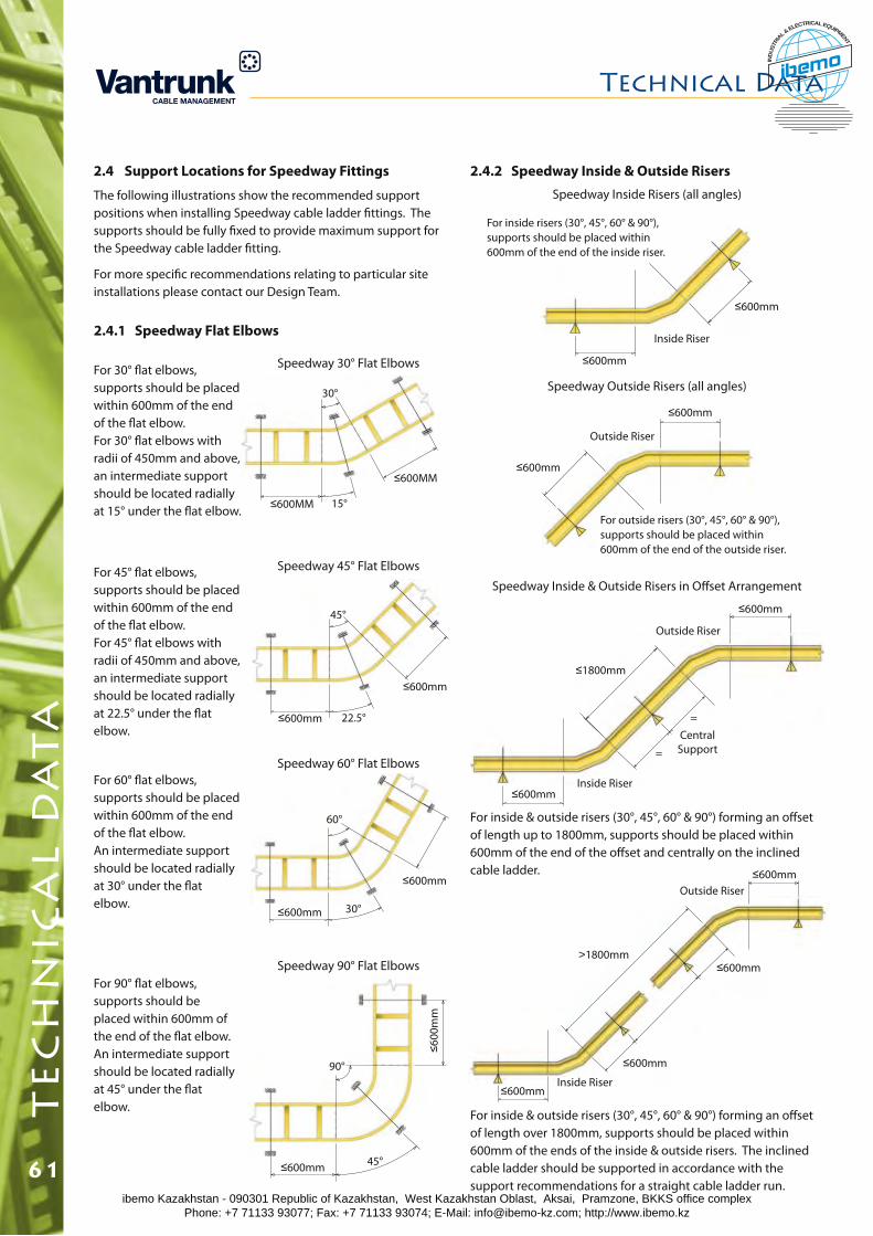
For 30° flat elbows, supports should be placed within 600mm of the end of the flat elbow. For 30° flat elbows with radii of 450mm and above, an intermediate support should be located radially at 15° under the flat elbow.
For 60° flat elbows, supports should be placed within 600mm of the end of the flat elbow. An intermediate support should be located radially at 30° under the flat elbow.
60°
≤600mm 30°
≤600mm
For 90° flat elbows, supports should be placed within 600mm of the end of the flat elbow. An intermediate support should be located radially at 45° under the flat elbow.
90°
≤600mm 45°
≤600
mm
Inside Riser
≤600mm
≤600mm
≤600mm
≤600mm
Outside Riser
For inside risers (30°, 45°, 60° & 90°), supports should be placed within 600mm of the end of the inside riser.
For outside risers (30°, 45°, 60° & 90°), supports should be placed within 600mm of the end of the outside riser.
2.4.2 Speedway Inside & Outside Risers
Speedway Inside & Outside Risers in Offset Arrangement
For inside & outside risers (30°, 45°, 60° & 90°) forming an offset of length over 1800mm, supports should be placed within 600mm of the ends of the inside & outside risers. The inclined cable ladder should be supported in accordance with the support recommendations for a straight cable ladder run.
For inside & outside risers (30°, 45°, 60° & 90°) forming an offset of length up to 1800mm, supports should be placed within 600mm of the end of the offset and centrally on the inclined cable ladder.
2.4 Support Locations for Speedway Fittings
The following illustrations show the recommended support positions when installing Speedway cable ladder fittings. The supports should be fully fixed to provide maximum support for the Speedway cable ladder fitting.
For more specific recommendations relating to particular site installations please contact our Design Team.
2.4.1 Speedway Flat Elbows
For 45° flat elbows, supports should be placed within 600mm of the end of the flat elbow. For 45° flat elbows with radii of 450mm and above, an intermediate support should be located radially at 22.5° under the flat elbow.
Speedway 30° Flat Elbows
Speedway 45° Flat Elbows
30°
≤600MM 15°
≤600MM
45°
≤600mm 22.5°
≤600mm
Speedway 60° Flat Elbows
Speedway 90° Flat Elbows
Speedway Outside Risers (all angles)
Speedway Inside Risers (all angles)
≤600mmInside Riser
≤600mm
≤1800mm
Central Support
=
=
Outside Riser
>1800mm
≤600mmInside Riser
≤600mm
≤600mmOutside Riser
≤600mm
Technical Datat
ec
hn
ica
l d
at
a
61ibemo Kazakhstan - 090301 Republic of Kazakhstan, West Kazakhstan Oblast, Aksai, Pramzone, BKKS office complex Phone: +7 71133 93077; Fax: +7 71133 93074; E-Mail: [email protected]; http://www.ibemo.kz
ibemoIND
USTR
IA
L & ELECTRICAL EQUIPMENT
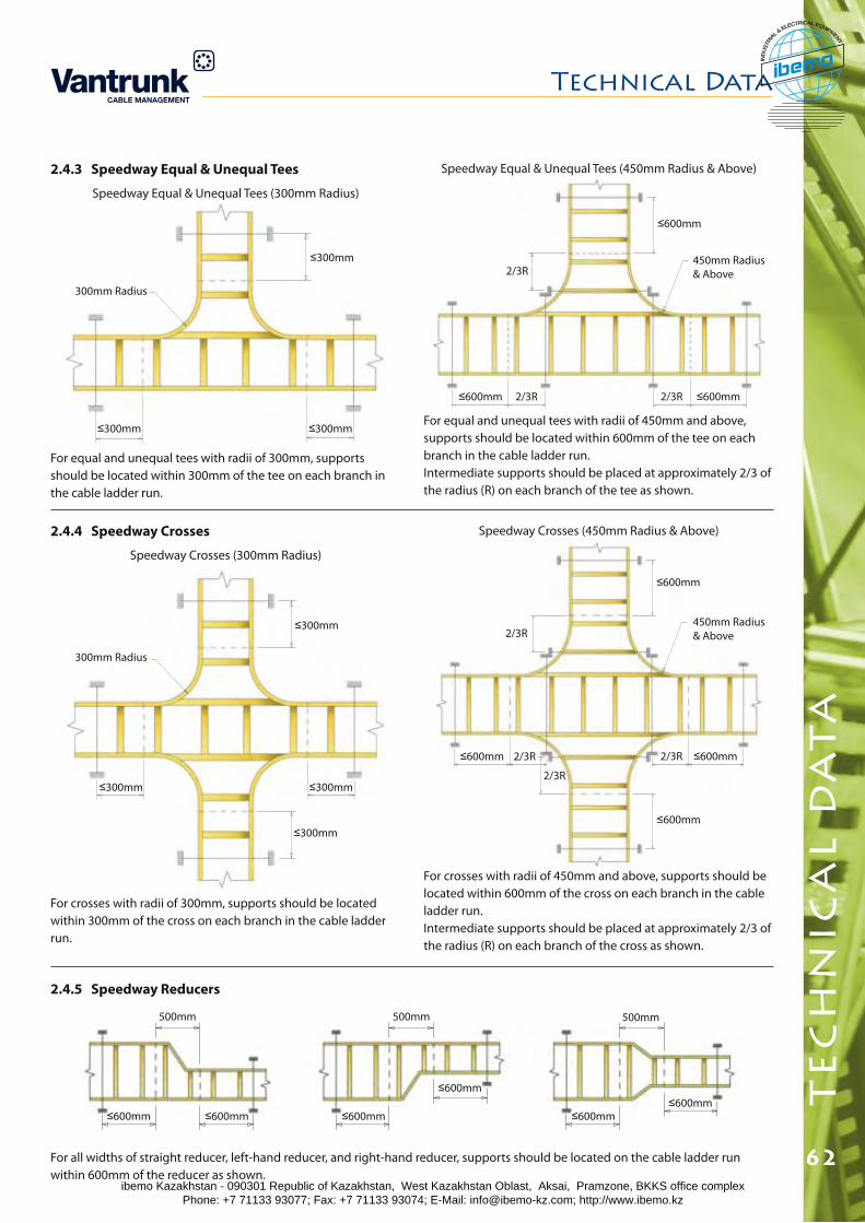
Technical Data
62
te
ch
nic
al
da
ta
2.4.3 Speedway Equal & Unequal Tees
Speedway Equal & Unequal Tees (300mm Radius)
2.4.4 Speedway Crosses
Speedway Crosses (300mm Radius)
≤300mm
300mm Radius
≤300mm≤300mm
≤600mm ≤600mm2/3R2/3R
2/3R450mm Radius & Above
For equal and unequal tees with radii of 450mm and above, supports should be located within 600mm of the tee on each branch in the cable ladder run. Intermediate supports should be placed at approximately 2/3 of the radius (R) on each branch of the tee as shown.
Speedway Equal & Unequal Tees (450mm Radius & Above)
For equal and unequal tees with radii of 300mm, supports should be located within 300mm of the tee on each branch in the cable ladder run.
For crosses with radii of 300mm, supports should be located within 300mm of the cross on each branch in the cable ladder run.
For crosses with radii of 450mm and above, supports should be located within 600mm of the cross on each branch in the cable ladder run. Intermediate supports should be placed at approximately 2/3 of the radius (R) on each branch of the cross as shown.
2.4.5 Speedway Reducers
Speedway Crosses (450mm Radius & Above)
For all widths of straight reducer, left-hand reducer, and right-hand reducer, supports should be located on the cable ladder run within 600mm of the reducer as shown.
300mm Radius
≤300mm ≤300mm
≤300mm
≤300mm
≤600mm
2/3R
≤600mm
2/3R
≤600mm
450mm Radius & Above
500mm
≤600mm
≤600mm
500mm
≤600mm≤600mm
500mm
≤600mm ≤600mm
≤600mm
2/3R
≤600mm
2/3R
ibemo Kazakhstan - 090301 Republic of Kazakhstan, West Kazakhstan Oblast, Aksai, Pramzone, BKKS office complex Phone: +7 71133 93077; Fax: +7 71133 93074; E-Mail: [email protected]; http://www.ibemo.kz
ibemoIND
USTR
IA
L & ELECTRICAL EQUIPMENT
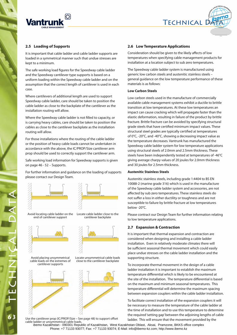
2.7 Expansion & Contraction
It is important that thermal expansion and contraction are considered when designing and installing a cable ladder installation. Even in relatively moderate climates there will be sufficient seasonal thermal movement which could easily place undue stresses on the cable ladder installation and the supporting structure.
To incorporate thermal movement in the design of a cable ladder installation it is important to establish the maximum temperature differential which is likely to be encountered at the site of the installation. The temperature differential is based on the maximum and minimum seasonal temperatures. This temperature differential will determine the maximum spacing between expansion couplers within the cable ladder installation.
To facilitate correct installation of the expansion couplers it will be necessary to measure the temperature of the cable ladder at the time of installation and to use this temperature to determine the required ‘setting gap’ between the adjoining lengths of cable ladder. This will ensure that the movement provided by the
2.5 Loading of Supports
It is important that cable ladder and cable ladder supports are loaded in a symmetrical manner such that undue stresses are kept to a minimum.
The safe working load figures for the Speedway cable ladder and the Speedway cantilever type supports is based on a uniform loading within the Speedway cable ladder and on the assumption that the correct length of cantilever is used in each case.
Where cantilevers of additional length are used to support Speedway cable ladder, care should be taken to position the cable ladder as close to the backplate of the cantilever as the installation routing will allow.
Where the Speedway cable ladder is not filled to capacity, or is carrying heavy cables, care should be taken to position the cables as close to the cantilever backplate as the installation routing will allow.
For those installations where the routing of the cable ladder or the position of heavy cable loads cannot be undertaken in accordance with the above, the IC/PROP/Size cantilever arm prop should be used to correctly support the cantilever arm.
Safe working load information for Speedway supports is given on page 46 - 52 – Supports.
For further information and guidance on the loading of supports please contact our Design Team.
Use the cantilever prop (IC/PROP/Size – See page 48) to support offset cable ladder or unsymmetrical cable loads.
Avoid locating cable ladder on the end of cantilever support
Avoid placing unsymmetrical cable loads on the extremes of
cantilever supports
Locate unsymmetrical cable loads close to the cantilever backplate
Locate cable ladder close to the cantilever backplate
2.6 Low Temperature Applications
Consideration should be given to the likely affects of low temperatures when specifying cable management products for installation at a location subject to sub zero temperatures.
The Speedway cable ladder system is manufactured using generic low carbon steels and austenitic stainless steels – general guidance on the low temperature performance of these materials is as follows:
Low Carbon Steels
Low carbon steels used in the manufacture of commercially available cable management systems exhibit a ductile to brittle transition at low temperatures. At these low temperatures an impact can cause cracking which will propagate faster than the elastic deformation, resulting in failure of the product by brittle fracture. Brittle fracture can be avoided by specifying structural grade steels that have certified minimum impact values. These structural steel grades are typically certified at temperatures of 0°C, -20°C, and -40°C, showing a decreasing impact value as the temperature decreases. Vantrunk has manufactured the Speedway cable ladder system for low temperature applications using structural steels of 2.0mm and 2.5mm thickness. These steels have been independently tested at temperatures of -46°C giving average charpy values of 20 joules for 2.0mm thickness and 30 joules for 2.5mm thickness.
Austenitic Stainless Steels
Austenitic stainless steels, including grade 1:4404 to BS EN 10088-2 (marine grade 316) which is used in the manufacture of the Speedway cable ladder system and accessories, are not affected by sub zero temperatures. These stainless steels do not suffer a loss in either ductility or toughness and are not susceptible to failure by brittle fracture at low temperatures below -20°C.
Please contract our Design Team for further information relating to low temperature applications.
Technical Datat
ec
hn
ica
l d
at
a
63ibemo Kazakhstan - 090301 Republic of Kazakhstan, West Kazakhstan Oblast, Aksai, Pramzone, BKKS office complex Phone: +7 71133 93077; Fax: +7 71133 93074; E-Mail: [email protected]; http://www.ibemo.kz
ibemoIND
USTR
IA
L & ELECTRICAL EQUIPMENT
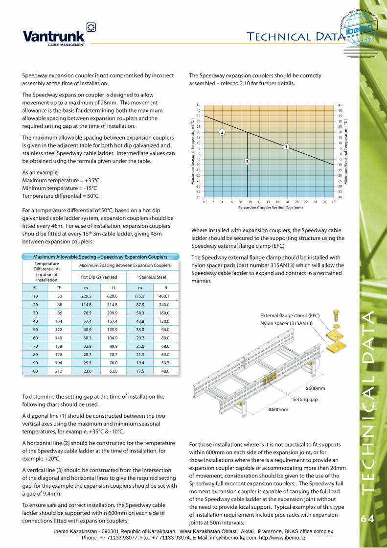
Technical Data
64
te
ch
nic
al
da
ta
Where installed with expansion couplers, the Speedway cable ladder should be secured to the supporting structure using the Speedway external flange clamp (EFC)
The Speedway external flange clamp should be installed with nylon spacer pads (part number 315AN13) which will allow the Speedway cable ladder to expand and contract in a restrained manner.
Setting gap
External flange clamp (EFC)
≤600mm
Nylon spacer (315AN13)
≤600mm
Temperature Differential At
Location of Installation
Maximum Spacing Between Expansion Couplers
Hot Dip Galvanized Stainless Steel
°C °F m ft m ft
10 50 229.5 629.6 175.0 480.1
20 68 114.8 314.8 87.5 240.0
30 86 76.5 209.9 58.3 160.0
40 104 57.4 157.4 43.8 120.0
50 122 45.9 125.9 35.0 96.0
60 140 38.3 104.9 29.2 80.0
70 158 32.8 89.9 25.0 68.6
80 176 28.7 78.7 21.9 60.0
90 194 25.5 70.0 19.4 53.3
100 212 23.0 63.0 17.5 48.0
Maximum Allowable Spacing – Speedway Expansion Couplers
For a temperature differential of 50°C, based on a hot dip galvanized cable ladder system, expansion couplers should be fitted every 46m. For ease of installation, expansion couplers should be fitted at every 15th 3m cable ladder, giving 45m between expansion couplers.
45
40
35
30
25
20
15
10
5
0
-5
-10
-15
-20
-25
-30
-35
-40
45
40
35
30
25
20
15
10
5
0
-5
-10
-15
-20
-25
-30
-35
-400 2 4 6 8 10 12 14 16 18 20 22 24 26 28
Expansion Coupler Setting Gap (mm)
Min
imu
m S
easo
nal
Tem
per
atu
re (
oC
)
Max
imu
m S
easo
nal
Tem
per
atu
re (
oC
)
2
3
1
The Speedway expansion couplers should be correctly assembled – refer to 2.10 for further details.
To determine the setting gap at the time of installation the following chart should be used.
A diagonal line (1) should be constructed between the two vertical axes using the maximum and minimum seasonal temperatures, for example, +35°C & -10°C.
A horizontal line (2) should be constructed for the temperature of the Speedway cable ladder at the time of installation, for example +20°C.
A vertical line (3) should be constructed from the intersection of the diagonal and horizontal lines to give the required setting gap, for this example the expansion couplers should be set with a gap of 9.4mm.
To ensure safe and correct installation, the Speedway cable ladder should be supported within 600mm on each side of connections fitted with expansion couplers.
Speedway expansion coupler is not compromised by incorrect assembly at the time of installation.
The Speedway expansion coupler is designed to allow movement up to a maximum of 28mm. This movement allowance is the basis for determining both the maximum allowable spacing between expansion couplers and the required setting gap at the time of installation.
The maximum allowable spacing between expansion couplers is given in the adjacent table for both hot dip galvanized and stainless steel Speedway cable ladder. Intermediate values can be obtained using the formula given under the table.
As an example: Maximum temperature = +35°C Minimum temperature = -15°C Temperature differential = 50°C
For those installations where is it is not practical to fit supports within 600mm on each side of the expansion joint, or for those installations where there is a requirement to provide an expansion coupler capable of accommodating more than 28mm of movement, consideration should be given to the use of the Speedway full moment expansion couplers. The Speedway full moment expansion coupler is capable of carrying the full load of the Speedway cable ladder at the expansion joint without the need to provide local support. Typical examples of this type of installation requirement include pipe racks with expansion joints at 50m intervals.
ibemo Kazakhstan - 090301 Republic of Kazakhstan, West Kazakhstan Oblast, Aksai, Pramzone, BKKS office complex Phone: +7 71133 93077; Fax: +7 71133 93074; E-Mail: [email protected]; http://www.ibemo.kz
ibemoIND
USTR
IA
L & ELECTRICAL EQUIPMENT
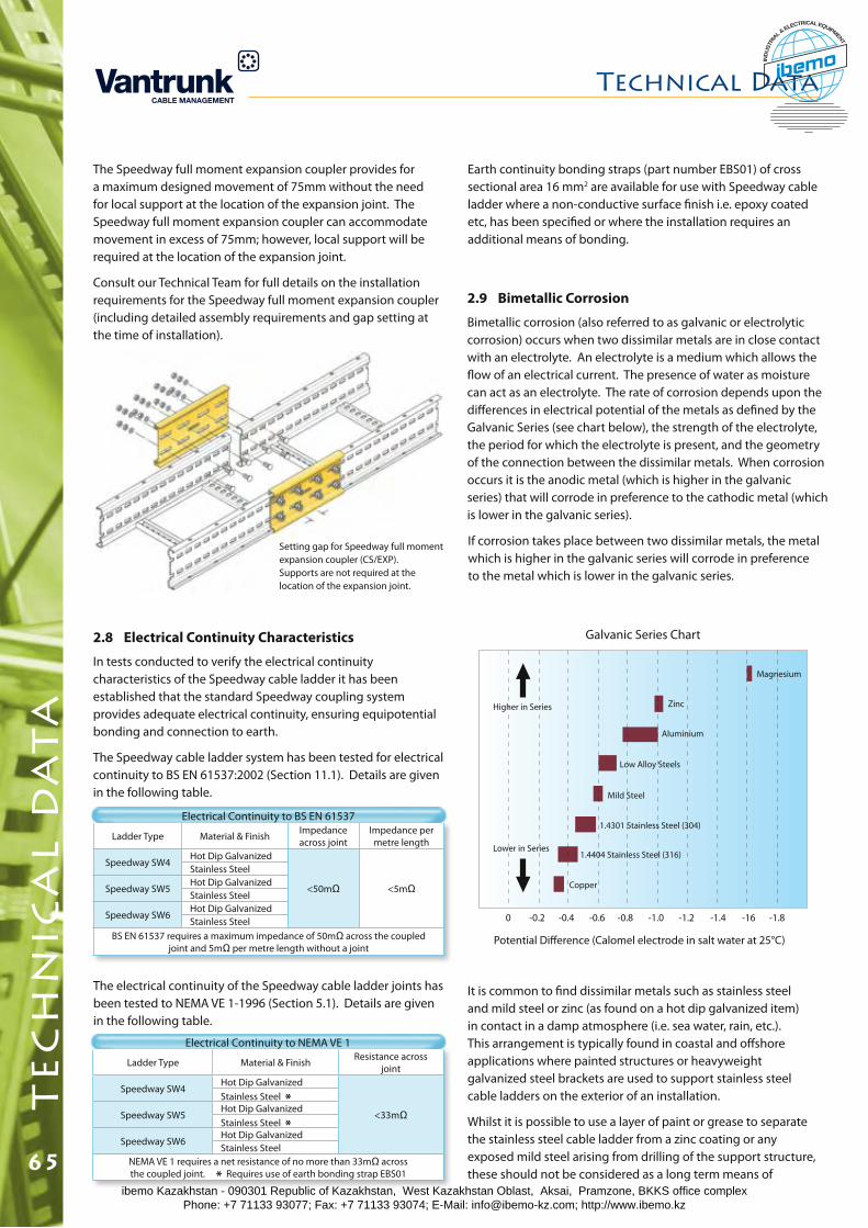
Potential Difference (Calomel electrode in salt water at 25°C)
0 -0.2 -0.4 -0.6 -0.8 -1.0 -1.2 -1.4 -16 -1.8
Magnesium
Aluminium
Zinc
Low Alloy Steels
Mild Steel
Copper
1.4404 Stainless Steel (316)
Higher in Series
Lower in Series
1.4301 Stainless Steel (304)
If corrosion takes place between two dissimilar metals, the metal which is higher in the galvanic series will corrode in preference to the metal which is lower in the galvanic series.
Ladder Type Material & Finish Impedance across joint
Impedance per metre length
Speedway SW4Hot Dip Galvanized
<50mΩ <5mΩ
Stainless Steel
Speedway SW5Hot Dip GalvanizedStainless Steel
Speedway SW6Hot Dip GalvanizedStainless Steel
BS EN 61537 requires a maximum impedance of 50mΩ across the coupled joint and 5mΩ per metre length without a joint
2.8 Electrical Continuity Characteristics
In tests conducted to verify the electrical continuity characteristics of the Speedway cable ladder it has been established that the standard Speedway coupling system provides adequate electrical continuity, ensuring equipotential bonding and connection to earth.
The Speedway cable ladder system has been tested for electrical continuity to BS EN 61537:2002 (Section 11.1). Details are given in the following table.
Electrical Continuity to BS EN 61537
The electrical continuity of the Speedway cable ladder joints has been tested to NEMA VE 1-1996 (Section 5.1). Details are given in the following table.
Ladder Type Material & Finish Resistance across joint
Speedway SW4Hot Dip Galvanized
<33mΩ
Stainless Steel *Speedway SW5
Hot Dip GalvanizedStainless Steel *
Speedway SW6Hot Dip GalvanizedStainless Steel
NEMA VE 1 requires a net resistance of no more than 33mΩ across the coupled joint. * Requires use of earth bonding strap EBS01
Electrical Continuity to NEMA VE 1
Earth continuity bonding straps (part number EBS01) of cross sectional area 16 mm2 are available for use with Speedway cable ladder where a non-conductive surface finish i.e. epoxy coated etc, has been specified or where the installation requires an additional means of bonding.
2.9 Bimetallic Corrosion
Bimetallic corrosion (also referred to as galvanic or electrolytic corrosion) occurs when two dissimilar metals are in close contact with an electrolyte. An electrolyte is a medium which allows the flow of an electrical current. The presence of water as moisture can act as an electrolyte. The rate of corrosion depends upon the differences in electrical potential of the metals as defined by the Galvanic Series (see chart below), the strength of the electrolyte, the period for which the electrolyte is present, and the geometry of the connection between the dissimilar metals. When corrosion occurs it is the anodic metal (which is higher in the galvanic series) that will corrode in preference to the cathodic metal (which is lower in the galvanic series).
Galvanic Series Chart
The Speedway full moment expansion coupler provides for a maximum designed movement of 75mm without the need for local support at the location of the expansion joint. The Speedway full moment expansion coupler can accommodate movement in excess of 75mm; however, local support will be required at the location of the expansion joint.
Consult our Technical Team for full details on the installation requirements for the Speedway full moment expansion coupler (including detailed assembly requirements and gap setting at the time of installation).
It is common to find dissimilar metals such as stainless steel and mild steel or zinc (as found on a hot dip galvanized item) in contact in a damp atmosphere (i.e. sea water, rain, etc.). This arrangement is typically found in coastal and offshore applications where painted structures or heavyweight galvanized steel brackets are used to support stainless steel cable ladders on the exterior of an installation.
Whilst it is possible to use a layer of paint or grease to separate the stainless steel cable ladder from a zinc coating or any exposed mild steel arising from drilling of the support structure, these should not be considered as a long term means of
Technical Datat
ec
hn
ica
l d
at
a
65
Setting gap for Speedway full moment expansion coupler (CS/EXP). Supports are not required at the location of the expansion joint.
ibemo Kazakhstan - 090301 Republic of Kazakhstan, West Kazakhstan Oblast, Aksai, Pramzone, BKKS office complex Phone: +7 71133 93077; Fax: +7 71133 93074; E-Mail: [email protected]; http://www.ibemo.kz
ibemoIND
USTR
IA
L & ELECTRICAL EQUIPMENT
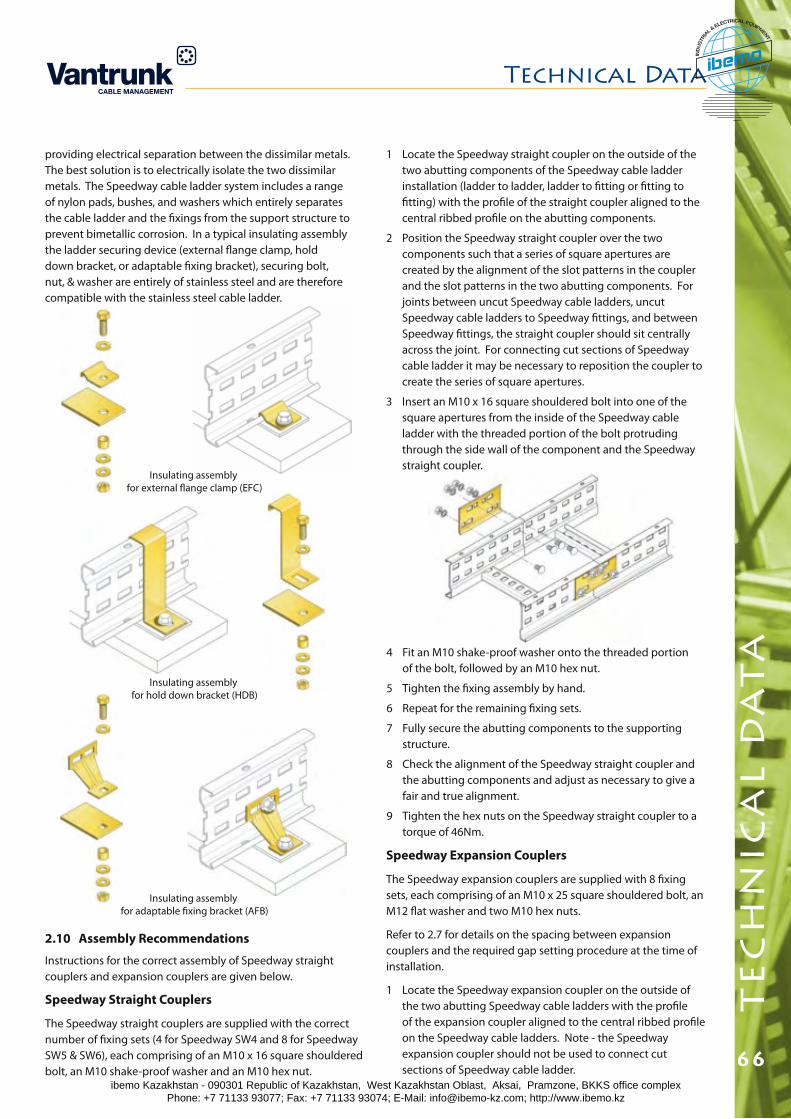
Technical Data
66
te
ch
nic
al
da
ta
Speedway Expansion Couplers
The Speedway expansion couplers are supplied with 8 fixing sets, each comprising of an M10 x 25 square shouldered bolt, an M12 flat washer and two M10 hex nuts.
Refer to 2.7 for details on the spacing between expansion couplers and the required gap setting procedure at the time of installation.
1 Locate the Speedway expansion coupler on the outside of the two abutting Speedway cable ladders with the profile of the expansion coupler aligned to the central ribbed profile on the Speedway cable ladders. Note - the Speedway expansion coupler should not be used to connect cut sections of Speedway cable ladder.
2.10 Assembly Recommendations
Instructions for the correct assembly of Speedway straight couplers and expansion couplers are given below.
Speedway Straight Couplers
The Speedway straight couplers are supplied with the correct number of fixing sets (4 for Speedway SW4 and 8 for Speedway SW5 & SW6), each comprising of an M10 x 16 square shouldered bolt, an M10 shake-proof washer and an M10 hex nut.
4 Fit an M10 shake-proof washer onto the threaded portion of the bolt, followed by an M10 hex nut.
5 Tighten the fixing assembly by hand.
6 Repeat for the remaining fixing sets.
7 Fully secure the abutting components to the supporting structure.
8 Check the alignment of the Speedway straight coupler and the abutting components and adjust as necessary to give a fair and true alignment.
9 Tighten the hex nuts on the Speedway straight coupler to a torque of 46Nm.
Insulating assembly for adaptable fixing bracket (AFB)
Insulating assembly for external flange clamp (EFC)
Insulating assembly for hold down bracket (HDB)
providing electrical separation between the dissimilar metals. The best solution is to electrically isolate the two dissimilar metals. The Speedway cable ladder system includes a range of nylon pads, bushes, and washers which entirely separates the cable ladder and the fixings from the support structure to prevent bimetallic corrosion. In a typical insulating assembly the ladder securing device (external flange clamp, hold down bracket, or adaptable fixing bracket), securing bolt, nut, & washer are entirely of stainless steel and are therefore compatible with the stainless steel cable ladder.
1 Locate the Speedway straight coupler on the outside of the two abutting components of the Speedway cable ladder installation (ladder to ladder, ladder to fitting or fitting to fitting) with the profile of the straight coupler aligned to the central ribbed profile on the abutting components.
2 Position the Speedway straight coupler over the two components such that a series of square apertures are created by the alignment of the slot patterns in the coupler and the slot patterns in the two abutting components. For joints between uncut Speedway cable ladders, uncut Speedway cable ladders to Speedway fittings, and between Speedway fittings, the straight coupler should sit centrally across the joint. For connecting cut sections of Speedway cable ladder it may be necessary to reposition the coupler to create the series of square apertures.
3 Insert an M10 x 16 square shouldered bolt into one of the square apertures from the inside of the Speedway cable ladder with the threaded portion of the bolt protruding through the side wall of the component and the Speedway straight coupler.
ibemo Kazakhstan - 090301 Republic of Kazakhstan, West Kazakhstan Oblast, Aksai, Pramzone, BKKS office complex Phone: +7 71133 93077; Fax: +7 71133 93074; E-Mail: [email protected]; http://www.ibemo.kz
ibemoIND
USTR
IA
L & ELECTRICAL EQUIPMENT
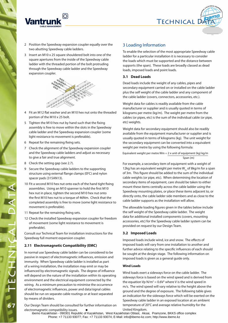
3.2 Imposed Loads
Imposed loads include wind, ice and snow. The effects of imposed loads will vary from one installation to another and further advice relating to the specific influences of each should be sought at the design stage. The following information on imposed loads is given as a general guide only.
Wind Loads
Wind loads exert a sideways force on the cable ladder. The sideways force is based on the wind speed and is derived from the equation Vp N/m2 = 0.6V2 where V is the wind speed in m/s. The wind speed will vary relative to the height above the ground and the degree of exposure. The following table gives an indication for the sideways force which will be exerted on the Speedway cable ladder in an exposed location at an ambient temperature of 20°C and average relative humidity for the United Kingdom.
4 Fit an M12 flat washer and an M10 hex nut onto the threaded portion of the M10 x 25 bolt.
5 Tighten the M10 hex nut by hand such that the fixing assembly is free to move within the slots in the Speedway cable ladder and the Speedway expansion coupler (some light resistance to movement is preferable).
6 Repeat for the remaining fixing sets.
7 Check the alignment of the Speedway expansion coupler and the Speedway cable ladders and adjust as necessary to give a fair and true alignment.
8 Check the setting gap (see 2.7).
9 Secure the Speedway cable ladders to the supporting structure using external flange clamps (EFC) and nylon spacer pads (315AN13).
10 Fit a second M10 hex nut onto each of the hand tight fixing assemblies. Using an M10 spanner to hold the first M10 hex nut in place, tighten the second M10 hex nut onto the first M10 hex nut to a torque of 46Nm. Check that the completed assembly is free to move (some light resistance to movement is preferable).
11 Repeat for the remaining fixing sets.
12 Check the installed Speedway expansion coupler for freedom of movement (some light resistance to movement is preferable).
Consult our Technical Team for installation instructions for the Speedway full moment expansion coupler.
2.11 Electromagnetic Compatibility (EMC)
In normal use Speedway cable ladder can be considered to be passive in respect of electromagnetic influences, emission and immunity. When Speedway cable ladder is installed as part of a wiring installation, the installation may emit or may be influenced by electromagnetic signals. The degree of influence will depend on the nature of the installation within its operating environment and the electrical equipment connected by the wiring. As a minimum precaution to minimise the occurrence of electromagnetic influences, power and data/signal cables should be run on separate cable routings or at least separated by means of dividers.
Our Design Team should be consulted for further information on electromagnetic compatibility issues.
3 Loading InformationTo enable the selection of the most appropriate Speedway cable ladder for a particular installation it is necessary to consider the loads which must be supported and the distance between supports (the span). These loads are broadly classed as dead loads, imposed loads and point loads.
3.1 Dead Loads
Dead loads include the weight of any cables, pipes and secondary equipment carried on or installed on the cable ladder plus the self weight of the cable ladder and any component of the cable ladder (covers, connectors, accessories, etc.).
Weight data for cables is readily available from the cable manufacturer or supplier and is usually quoted in terms of kilograms per metre (kg/m). The weight per metre from the cables (or pipes, etc) is the sum of the individual cable (or pipe, etc) weights.
Weight data for secondary equipment should also be readily available from the equipment manufacturer or supplier and is usually quoted in terms of kilograms (kg). The unit weight for the secondary equipment can be converted into a equivalent weight per metre by using the following formula:
Equivalent weight per metre Wm = 2 x unit of equipment (kg) kg/m
Span (m)
For example, a secondary item of equipment with a weight of 12kg has an equivalent weight per metre Wm of 8kg/m for a span of 3m. This figure should be added to the sum of the individual cable weights (or pipe, etc). When determining the location of secondary items of equipment, care should be taken to either mount these items centrally across the cable ladder using the Speedway mounting plates, or place these items adjacent to, or directly onto, the cable ladder side members and as close to the cable ladder supports as the installation will allow.
The allowable loading figures given in the tables below include the self weight of the Speedway cable ladder. The weight data for additional installed components (covers, mounting accessories, etc) for the Speedway cable ladder system can be provided on request by our Design Team.
2 Position the Speedway expansion coupler equally over the two abutting Speedway cable ladders.
3 Insert an M10 x 25 square shouldered bolt into one of the square apertures from the inside of the Speedway cable ladder with the threaded portion of the bolt protruding through the Speedway cable ladder and the Speedway expansion coupler.
Technical Datat
ec
hn
ica
l d
at
a
67ibemo Kazakhstan - 090301 Republic of Kazakhstan, West Kazakhstan Oblast, Aksai, Pramzone, BKKS office complex Phone: +7 71133 93077; Fax: +7 71133 93074; E-Mail: [email protected]; http://www.ibemo.kz
ibemoIND
USTR
IA
L & ELECTRICAL EQUIPMENT
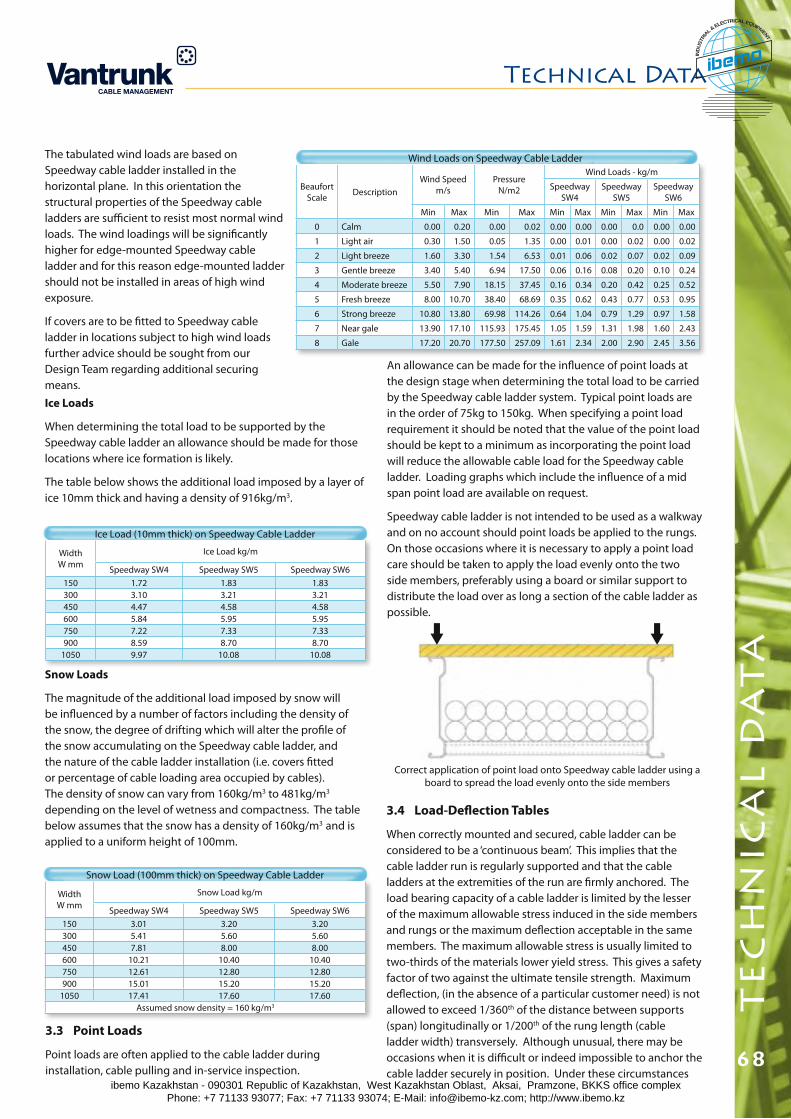
Technical Data
68
te
ch
nic
al
da
ta
3.4 Load-Deflection Tables
When correctly mounted and secured, cable ladder can be considered to be a ‘continuous beam’. This implies that the cable ladder run is regularly supported and that the cable ladders at the extremities of the run are firmly anchored. The load bearing capacity of a cable ladder is limited by the lesser of the maximum allowable stress induced in the side members and rungs or the maximum deflection acceptable in the same members. The maximum allowable stress is usually limited to two-thirds of the materials lower yield stress. This gives a safety factor of two against the ultimate tensile strength. Maximum deflection, (in the absence of a particular customer need) is not allowed to exceed 1/360th of the distance between supports (span) longitudinally or 1/200th of the rung length (cable ladder width) transversely. Although unusual, there may be occasions when it is difficult or indeed impossible to anchor the cable ladder securely in position. Under these circumstances
Snow Loads
The magnitude of the additional load imposed by snow will be influenced by a number of factors including the density of the snow, the degree of drifting which will alter the profile of the snow accumulating on the Speedway cable ladder, and the nature of the cable ladder installation (i.e. covers fitted or percentage of cable loading area occupied by cables). The density of snow can vary from 160kg/m3 to 481kg/m3 depending on the level of wetness and compactness. The table below assumes that the snow has a density of 160kg/m3 and is applied to a uniform height of 100mm.
WidthW mm
Snow Load kg/m
Speedway SW4 Speedway SW5 Speedway SW6150 3.01 3.20 3.20300 5.41 5.60 5.60450 7.81 8.00 8.00600 10.21 10.40 10.40750 12.61 12.80 12.80900 15.01 15.20 15.20
1050 17.41 17.60 17.60Assumed snow density = 160 kg/m3
Snow Load (100mm thick) on Speedway Cable Ladder
Correct application of point load onto Speedway cable ladder using a board to spread the load evenly onto the side members
WidthW mm
Ice Load kg/m
Speedway SW4 Speedway SW5 Speedway SW6150 1.72 1.83 1.83300 3.10 3.21 3.21450 4.47 4.58 4.58600 5.84 5.95 5.95750 7.22 7.33 7.33900 8.59 8.70 8.70
1050 9.97 10.08 10.08
Ice Load (10mm thick) on Speedway Cable Ladder
Ice Loads
When determining the total load to be supported by the Speedway cable ladder an allowance should be made for those locations where ice formation is likely.
The table below shows the additional load imposed by a layer of ice 10mm thick and having a density of 916kg/m3.
The tabulated wind loads are based on Speedway cable ladder installed in the horizontal plane. In this orientation the structural properties of the Speedway cable ladders are sufficient to resist most normal wind loads. The wind loadings will be significantly higher for edge-mounted Speedway cable ladder and for this reason edge-mounted ladder should not be installed in areas of high wind exposure.
If covers are to be fitted to Speedway cable ladder in locations subject to high wind loads further advice should be sought from our Design Team regarding additional securing means.
Beaufort Scale Description
Wind Speed m/s
Pressure N/m2
Wind Loads - kg/m
Speedway SW4
Speedway SW5
Speedway SW6
Min Max Min Max Min Max Min Max Min Max
0 Calm 0.00 0.20 0.00 0.02 0.00 0.00 0.00 0.0 0.00 0.00
1 Light air 0.30 1.50 0.05 1.35 0.00 0.01 0.00 0.02 0.00 0.02
2 Light breeze 1.60 3.30 1.54 6.53 0.01 0.06 0.02 0.07 0.02 0.09
3 Gentle breeze 3.40 5.40 6.94 17.50 0.06 0.16 0.08 0.20 0.10 0.24
4 Moderate breeze 5.50 7.90 18.15 37.45 0.16 0.34 0.20 0.42 0.25 0.52
5 Fresh breeze 8.00 10.70 38.40 68.69 0.35 0.62 0.43 0.77 0.53 0.95
6 Strong breeze 10.80 13.80 69.98 114.26 0.64 1.04 0.79 1.29 0.97 1.58
7 Near gale 13.90 17.10 115.93 175.45 1.05 1.59 1.31 1.98 1.60 2.43
8 Gale 17.20 20.70 177.50 257.09 1.61 2.34 2.00 2.90 2.45 3.56
Wind Loads on Speedway Cable Ladder
An allowance can be made for the influence of point loads at the design stage when determining the total load to be carried by the Speedway cable ladder system. Typical point loads are in the order of 75kg to 150kg. When specifying a point load requirement it should be noted that the value of the point load should be kept to a minimum as incorporating the point load will reduce the allowable cable load for the Speedway cable ladder. Loading graphs which include the influence of a mid span point load are available on request.
Speedway cable ladder is not intended to be used as a walkway and on no account should point loads be applied to the rungs. On those occasions where it is necessary to apply a point load care should be taken to apply the load evenly onto the two side members, preferably using a board or similar support to distribute the load over as long a section of the cable ladder as possible.
3.3 Point Loads
Point loads are often applied to the cable ladder during installation, cable pulling and in-service inspection.
ibemo Kazakhstan - 090301 Republic of Kazakhstan, West Kazakhstan Oblast, Aksai, Pramzone, BKKS office complex Phone: +7 71133 93077; Fax: +7 71133 93074; E-Mail: [email protected]; http://www.ibemo.kz
ibemoIND
USTR
IA
L & ELECTRICAL EQUIPMENT
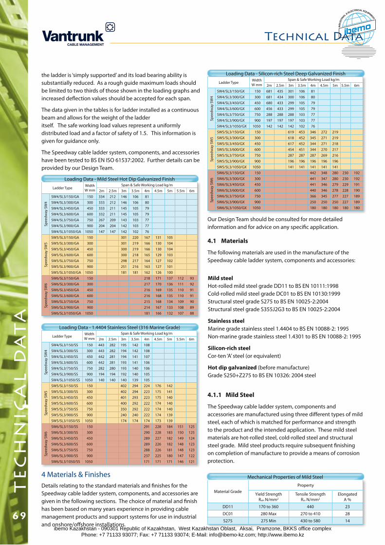
Ladder Type Width W mm
Span & Safe Working Load kg/m2m 2.5m 3m 3.5m 4m 4.5m 5m 5.5m 6m
Spee
dway
SW
4
SW4/SL3/150/SS 150 443 282 195 142 108SW4/SL3/300/SS 300 443 282 194 142 108SW4/SL3/450/SS 450 442 281 194 141 107SW4/SL3/600/SS 600 442 281 193 141 106SW4/SL3/750/SS 750 282 280 193 140 106SW4/SL3/900/SS 900 194 194 192 140 105SW4/SL3/1050/SS 1050 140 140 140 139 105
Spee
dway
SW
5
SW5/SL3/150/SS 150 402 294 224 176 142SW5/SL3/300/SS 300 402 294 223 175 141SW5/SL3/450/SS 450 401 293 223 175 140SW5/SL3/600/SS 600 400 292 222 174 140SW5/SL3/750/SS 750 350 292 222 174 140SW5/SL3/900/SS 900 240 240 222 174 139SW5/SL3/1050/SS 1050 174 174 174 173 139
Spee
dway
SW
6
SW6/SL3/150/SS 150 291 228 184 151 125SW6/SL3/300/SS 300 290 228 183 150 125SW6/SL3/450/SS 450 289 227 182 149 124SW6/SL3/600/SS 600 289 226 182 148 123SW6/SL3/750/SS 750 288 226 181 148 123SW6/SL3/900/SS 900 237 225 180 147 122SW6/SL3/1050/SS 1050 171 171 171 146 121
Loading Data - 1.4404 Stainless Steel (316 Marine Grade)
Ladder Type Width W mm
Span & Safe Working Load kg/m2m 2.5m 3m 3.5m 4m 4.5m 5m 5.5m 6m
Spee
dway
SW
4
SW4/SL3/150/GX 150 681 435 301 106 81SW4/SL3/300/GX 300 681 434 300 106 80SW4/SL3/450/GX 450 680 433 299 105 79SW4/SL3/600/GX 600 456 433 299 105 79SW4/SL3/750/GX 750 288 288 288 103 77SW4/SL3/900/GX 900 197 197 197 103 77SW4/SL3/1050/GX 1050 142 142 142 102 76
Spee
dway
SW
5
SW5/SL3/150/GX 150 619 453 346 272 219SW5/SL3/300/GX 300 618 452 345 271 219SW5/SL3/450/GX 450 617 452 344 271 218SW5/SL3/600/GX 600 454 451 344 270 217SW5/SL3/750/GX 750 287 287 287 269 216SW5/SL3/900/GX 900 196 196 196 196 196SW5/SL3/1050/GX 1050 141 141 141 141 141
Spee
dway
SW
6
SW6/SL3/150/GX 150 442 348 280 230 192SW6/SL3/300/GX 300 441 347 280 230 192SW6/SL3/450/GX 450 441 346 279 229 191SW6/SL3/600/GX 600 440 346 278 228 190SW6/SL3/750/GX 750 366 345 277 227 189SW6/SL3/900/GX 900 250 250 250 227 189SW6/SL3/1050/GX 1050 180 180 180 180 180
Loading Data - Silicon-rich Steel Deep Galvanized Finish
4 Materials & FinishesDetails relating to the standard materials and finishes for the Speedway cable ladder system, components, and accessories are given in the following sections. The choice of material and finish has been based on many years experience in providing cable management products and support systems for use in industrial and onshore/offshore installations.
Mild steelHot-rolled mild steel grade DD11 to BS EN 10111:1998Cold-rolled mild steel grade DC01 to BS EN 10130:1999Structural steel grade S275 to BS EN 10025-2:2004 Structural steel grade S355J2G3 to BS EN 10025-2:2004
Stainless steelMarine grade stainless steel 1.4404 to BS EN 10088-2: 1995Non-marine grade stainless steel 1.4301 to BS EN 10088-2: 1995
Silicon-rich steelCor-ten ‘A’ steel (or equivalent)
Hot dip galvanized (before manufacture)Grade S250+Z275 to BS EN 10326: 2004 steel
4.1.1 Mild Steel
The Speedway cable ladder system, components and accessories are manufactured using three different types of mild steel, each of which is matched for performance and strength to the product and the intended application. These mild steel materials are hot-rolled steel, cold-rolled steel and structural steel grade. Mild steel products require subsequent finishing on completion of manufacture to provide a means of corrosion protection.
Ladder Type Width W mm
Span & Safe Working Load kg/m2m 2.5m 3m 3.5m 4m 4.5m 5m 5.5m 6m
Spee
dway
SW
4
SW4/SL3/150/GA 150 334 212 146 106 81SW4/SL3/300/GA 300 333 212 146 106 80SW4/SL3/450/GA 450 333 211 145 105 79SW4/SL3/600/GA 600 332 211 145 105 79SW4/SL3/750/GA 750 267 209 143 103 77SW4/SL3/900/GA 900 204 204 142 103 77SW4/SL3/1050/GA 1050 147 147 142 102 76
Spee
dway
SW
5
SW5/SL3/150/GA 150 301 220 167 131 105SW5/SL3/300/GA 300 301 219 166 130 104SW5/SL3/450/GA 450 300 219 166 130 104SW5/SL3/600/GA 600 300 218 165 129 103SW5/SL3/750/GA 750 298 217 164 127 102SW5/SL3/900/GA 900 251 216 163 127 101SW5/SL3/1050/GA 1050 181 181 162 126 100
Spee
dway
SW
6
SW6/SL3/150/GA 150 218 171 137 112 93SW6/SL3/300/GA 300 217 170 136 111 92SW6/SL3/450/GA 450 216 169 135 110 91SW6/SL3/600/GA 600 216 168 135 110 91SW6/SL3/750/GA 750 215 168 134 109 90SW6/SL3/900/GA 900 214 167 133 108 89SW6/SL3/1050/GA 1050 181 166 132 107 88
Loading Data - Mild Steel Hot Dip Galvanized Finish
the ladder is ‘simply supported’ and its load bearing ability is substantially reduced. As a rough guide maximum loads should be limited to two thirds of those shown in the loading graphs and increased deflection values should be accepted for each span.
The data given in the tables is for ladder installed as a continuous beam and allows for the weight of the ladder itself. The safe working load values represent a uniformly distributed load and a factor of safety of 1.5. This information is given for guidance only.
The Speedway cable ladder system, components, and accessories have been tested to BS EN ISO 61537:2002. Further details can be provided by our Design Team.
Technical Datat
ec
hn
ica
l d
at
a
69
Material GradeProperty
Yield StrengthReH N/mm2
Tensile StrengthRm N/mm2
ElongatedA %
DD11 170 to 360 440 23
DC01 280 Max 270 to 410 28
S275 275 Min 430 to 580 14
Mechanical Properties of Mild Steel
Our Design Team should be consulted for more detailed information and for advice on any specific application.
4.1 Materials
The following materials are used in the manufacture of the Speedway cable ladder system, components and accessories:
ibemo Kazakhstan - 090301 Republic of Kazakhstan, West Kazakhstan Oblast, Aksai, Pramzone, BKKS office complex Phone: +7 71133 93077; Fax: +7 71133 93074; E-Mail: [email protected]; http://www.ibemo.kz
ibemoIND
USTR
IA
L & ELECTRICAL EQUIPMENT
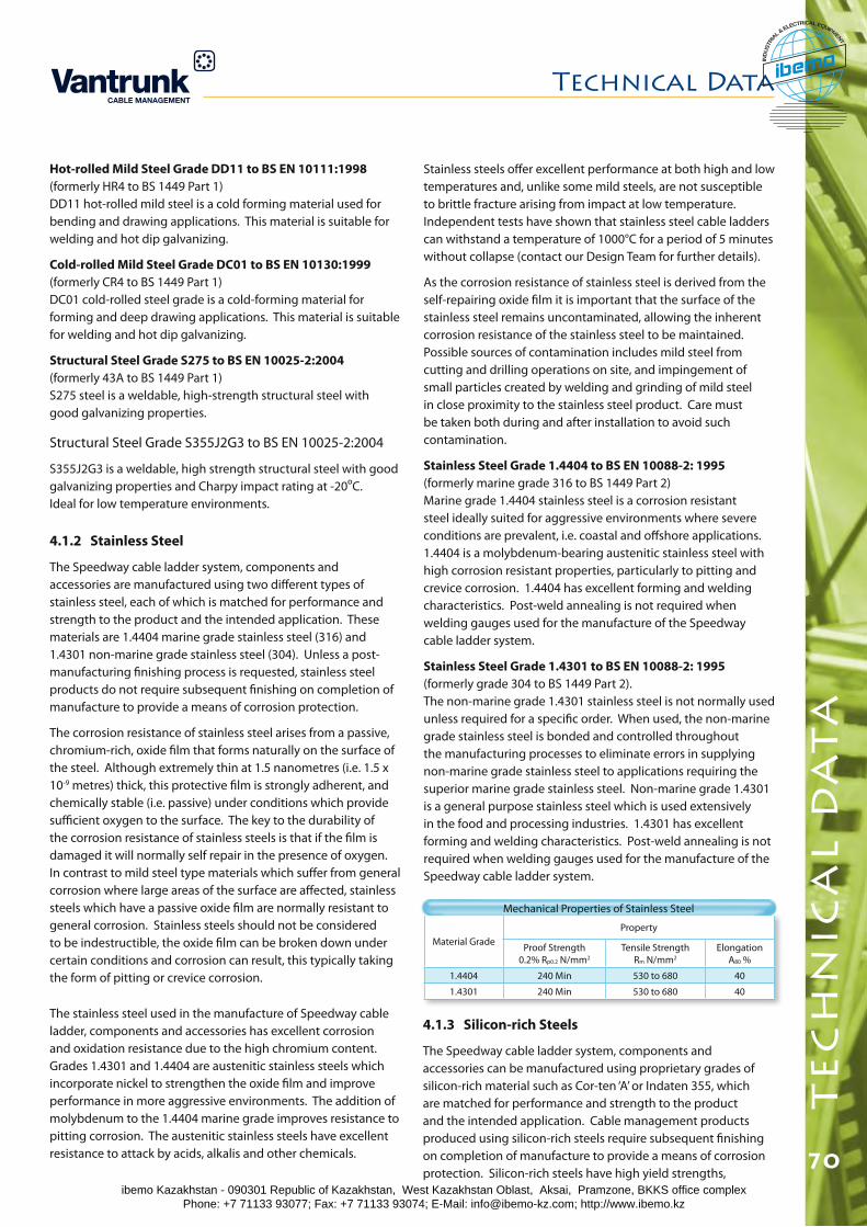
Technical Data
70
te
ch
nic
al
da
ta
The stainless steel used in the manufacture of Speedway cable ladder, components and accessories has excellent corrosion and oxidation resistance due to the high chromium content. Grades 1.4301 and 1.4404 are austenitic stainless steels which incorporate nickel to strengthen the oxide film and improve performance in more aggressive environments. The addition of molybdenum to the 1.4404 marine grade improves resistance to pitting corrosion. The austenitic stainless steels have excellent resistance to attack by acids, alkalis and other chemicals.
Material GradeProperty
Proof Strength0.2% Rp0.2 N/mm2
Tensile StrengthRm N/mm2
ElongationA80 %
1.4404 240 Min 530 to 680 40
1.4301 240 Min 530 to 680 40
Mechanical Properties of Stainless Steel
4.1.3 Silicon-rich Steels
The Speedway cable ladder system, components and accessories can be manufactured using proprietary grades of silicon-rich material such as Cor-ten ‘A’ or Indaten 355, which are matched for performance and strength to the product and the intended application. Cable management products produced using silicon-rich steels require subsequent finishing on completion of manufacture to provide a means of corrosion protection. Silicon-rich steels have high yield strengths,
Structural Steel Grade S355J2G3 to BS EN 10025-2:2004
S355J2G3 is a weldable, high strength structural steel with good galvanizing properties and Charpy impact rating at -20ºC. Ideal for low temperature environments.
4.1.2 Stainless Steel
The Speedway cable ladder system, components and accessories are manufactured using two different types of stainless steel, each of which is matched for performance and strength to the product and the intended application. These materials are 1.4404 marine grade stainless steel (316) and 1.4301 non-marine grade stainless steel (304). Unless a post-manufacturing finishing process is requested, stainless steel products do not require subsequent finishing on completion of manufacture to provide a means of corrosion protection.
The corrosion resistance of stainless steel arises from a passive, chromium-rich, oxide film that forms naturally on the surface of the steel. Although extremely thin at 1.5 nanometres (i.e. 1.5 x 10⁻⁹ metres) thick, this protective film is strongly adherent, and chemically stable (i.e. passive) under conditions which provide sufficient oxygen to the surface. The key to the durability of the corrosion resistance of stainless steels is that if the film is damaged it will normally self repair in the presence of oxygen. In contrast to mild steel type materials which suffer from general corrosion where large areas of the surface are affected, stainless steels which have a passive oxide film are normally resistant to general corrosion. Stainless steels should not be considered to be indestructible, the oxide film can be broken down under certain conditions and corrosion can result, this typically taking the form of pitting or crevice corrosion.
Stainless steels offer excellent performance at both high and low temperatures and, unlike some mild steels, are not susceptible to brittle fracture arising from impact at low temperature. Independent tests have shown that stainless steel cable ladders can withstand a temperature of 1000°C for a period of 5 minutes without collapse (contact our Design Team for further details).
As the corrosion resistance of stainless steel is derived from the self-repairing oxide film it is important that the surface of the stainless steel remains uncontaminated, allowing the inherent corrosion resistance of the stainless steel to be maintained. Possible sources of contamination includes mild steel from cutting and drilling operations on site, and impingement of small particles created by welding and grinding of mild steel in close proximity to the stainless steel product. Care must be taken both during and after installation to avoid such contamination.
Stainless Steel Grade 1.4404 to BS EN 10088-2: 1995 (formerly marine grade 316 to BS 1449 Part 2) Marine grade 1.4404 stainless steel is a corrosion resistant steel ideally suited for aggressive environments where severe conditions are prevalent, i.e. coastal and offshore applications. 1.4404 is a molybdenum-bearing austenitic stainless steel with high corrosion resistant properties, particularly to pitting and crevice corrosion. 1.4404 has excellent forming and welding characteristics. Post-weld annealing is not required when welding gauges used for the manufacture of the Speedway cable ladder system.
Stainless Steel Grade 1.4301 to BS EN 10088-2: 1995 (formerly grade 304 to BS 1449 Part 2). The non-marine grade 1.4301 stainless steel is not normally used unless required for a specific order. When used, the non-marine grade stainless steel is bonded and controlled throughout the manufacturing processes to eliminate errors in supplying non-marine grade stainless steel to applications requiring the superior marine grade stainless steel. Non-marine grade 1.4301 is a general purpose stainless steel which is used extensively in the food and processing industries. 1.4301 has excellent forming and welding characteristics. Post-weld annealing is not required when welding gauges used for the manufacture of the Speedway cable ladder system.
Hot-rolled Mild Steel Grade DD11 to BS EN 10111:1998 (formerly HR4 to BS 1449 Part 1) DD11 hot-rolled mild steel is a cold forming material used for bending and drawing applications. This material is suitable for welding and hot dip galvanizing.
Cold-rolled Mild Steel Grade DC01 to BS EN 10130:1999 (formerly CR4 to BS 1449 Part 1) DC01 cold-rolled steel grade is a cold-forming material for forming and deep drawing applications. This material is suitable for welding and hot dip galvanizing.
Structural Steel Grade S275 to BS EN 10025-2:2004 (formerly 43A to BS 1449 Part 1) S275 steel is a weldable, high-strength structural steel with good galvanizing properties.
ibemo Kazakhstan - 090301 Republic of Kazakhstan, West Kazakhstan Oblast, Aksai, Pramzone, BKKS office complex Phone: +7 71133 93077; Fax: +7 71133 93074; E-Mail: [email protected]; http://www.ibemo.kz
ibemoIND
USTR
IA
L & ELECTRICAL EQUIPMENT
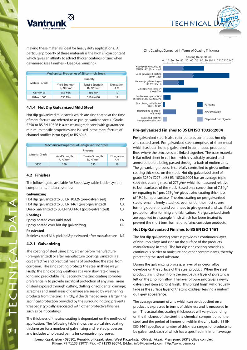
Zinc Coatings Compared in Terms of Coating Thickness
Pure zinc
Coating Thickness µm0 10 20 30 40 50 60 70 80 90 100 110 120 130 140
Zinc-iron alloy
Dispersed zinc pigment
Hot dip galvanised to BS EN ISO 1461 (6mm steel)
Deep galvanised coating (6mm steel)
Centrifuge galvanizing to BS 7371 Part 6
Zinc spraying to BS EN 22063: Zn4
Continuously galvanised sheet to BS EN 10326: Z275
Zinc plating to Fe/Zn5 of BS EN 12329
Sherardizing to grade 1 of BS 4921
Paints and coatings incorporating zinc dust
Pre-galvanized Finishes to BS EN ISO 10326:2004
Pre-galvanized steel is also referred to as continuous hot dip zinc coated steel. Pre-galvanized steel comprises of sheet metal which has been hot dip galvanized in continuous production lines where the processes are linked together. The base material is flat rolled sheet in coil form which is suitably treated and annealed before being passed through a bath of molten zinc. The galvanizing process is carefully controlled to give a uniform coating thickness on the steel. Hot dip galvanized steel of grade S250+Z275 to BS EN 10326:2004 has an average triple spot zinc coating mass of 275g/m2 which is measured relative to both surfaces of the steel. Based on a conversion of 7.14g/m2 equating to 1μm, 275g/m2 gives a zinc coating thickness of 19.25μm per surface. The zinc coating on pre-galvanized steels remains firmly attached, even under the most severe forming operations and continues to give general and sacrificial protection after forming and fabrication. Pre-galvanized steels are supplied in a spangle finish which has been treated to prevent the short term formation of zinc corrosion products.
Hot Dip Galvanized Finishes to BS EN ISO 1461
The hot dip galvanizing process provides a continuous layer of zinc-iron alloys and zinc on the surface of the products manufactured in steel. The hot dip zinc coating provides a continuous barrier to moisture and other contaminants, thereby protecting the steel substrate.
During the galvanizing process, a layer of zinc-iron alloy develops on the surface of the steel product. When the steel product is withdrawn from the zinc bath, a layer of pure zinc is left on the zinc-iron alloy. The layer of pure zinc gives a newly galvanized item a bright finish. This bright finish will gradually fade as the surface layer of the zinc oxidises, leaving a uniform dull grey appearance.
The average amount of zinc which can be deposited on a product is expressed in terms of thickness and is measured in μm. The actual zinc coating thicknesses will vary depending on the thickness of the steel, the chemical composition of the steel, and the period of immersion within the zinc bath. BS EN ISO 1461 specifies a number of thickness ranges for products to be galvanized, each of which has a specified minimum average
Material GradeProperty
Yield StrengthRp N/mm2
Tensile StrengthRm N/mm2
ElongationA %
Cor-ten ‘A’ 355 Min 480 Min 19
HiTrac 1000 355 Min 510 to 680 19
Mechanical Properties of Silicon-rich Steels
4.1.4 Hot Dip Galvanized Mild Steel
Hot dip galvanized mild steels which are zinc coated at the time of manufacture are referred to as pre-galvanized steels. Grade S250 to BS EN 10326 is a structural grade steel with guaranteed minimum tensile properties and is used in the manufacture of channel profiles (strut type) to BS 6946.
Material GradeProperty
Yield StrengthRp N/mm2
Tensile StrengthRm N/mm2
ElongationA %
S250 250 330 19
Mechanical Properties of Pre-galvanised Steel
GalvanizingHot dip galvanized to BS EN 10326 (pre-galvanized) PP Hot dip galvanized to BS EN 1461 (post-galvanized) GA Deep Galvanized to BS EN ISO 1461 (post-galvanized) GX
CoatingsEpoxy coated over mild steel EA Epoxy coated over hot dip galvanizing FA
PassivatedStainless steel 316, pickled & passivated after manufacture NS
4.2 Finishes
The following are available for Speedway cable ladder system, components, and accessories:
4.2.1 Galvanizing
The coating of steel using zinc, either before manufacture (pre-galvanized) or after manufacture (post-galvanized) is a cost effective and practical means of protecting the steel from corrosion. The zinc coating protects the steel in three ways. Firstly, the zinc coating weathers at a very slow rate giving a long and predictable life. Secondly, the zinc coating corrodes preferentially to provide sacrificial protection of any small areas of steel exposed through cutting, drilling, or accidental damage; scratches and small areas of damage are sealed by weathering products from the zinc. Thirdly, if the damaged area is larger, the sacrificial protection provided by the surrounding zinc prevents ‘creepage’ typically associated with other protective finishes such as paint coatings.
The thickness of the zinc coating is dependant on the method of application. The following table shows the typical zinc coating thicknesses for a number of galvanizing and related processes, and includes zinc-based paints for comparison purposes.
making these materials ideal for heavy duty applications. A particular property of these materials is the high silicon content which gives an affinity to attract thicker coatings of zinc when galvanized (see Finishes – Deep Galvanizing).
Technical Datat
ec
hn
ica
l d
at
a
71ibemo Kazakhstan - 090301 Republic of Kazakhstan, West Kazakhstan Oblast, Aksai, Pramzone, BKKS office complex Phone: +7 71133 93077; Fax: +7 71133 93074; E-Mail: [email protected]; http://www.ibemo.kz
ibemoIND
USTR
IA
L & ELECTRICAL EQUIPMENT
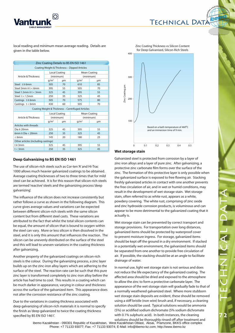
Technical Data
72
te
ch
nic
al
da
ta
Based on a bath temperature of 460oCand an immersion time of 9 min.
Silicon content of steel %0
100
200
300
400
0.1 0.2 0.3 0.4 0.5
Zin
c C
oat
ing
µm
Wet storage stain
Galvanized steel is protected from corrosion by a layer of zinc-iron alloys and a layer of pure zinc. After galvanizing, a protective zinc carbonate film forms over the surface of the zinc. The formation of this protective layer is only possible when the galvanized surface is exposed to free flowing air. Stacking freshly galvanized articles in contact with one another prevents the free circulation of air, and in wet or humid conditions, may result in the development of wet storage stain. Wet storage stain, often referred to as white rust, appears as a white, powdery covering. The white rust, comprising of zinc oxide and zinc hydroxide corrosion products, is voluminous and can appear to be more detrimental to the galvanized coating that it actually is.
Wet storage stain can be prevented by correct transport and storage provisions. For transportation over long distances, galvanized items should be protected by waterproof cover to prevent moisture ingress. For storage, galvanized items should be kept off the ground in a dry environment. If stacked in a potentially wet environment, the galvanized items should be separated from one another to provide free circulation of air. If possible, the stacking should be at an angle to facilitate drainage of water.
In normal use, light wet storage stain is not serious and does not reduce the life expectancy of the galvanized coating. The affected area should be dried and exposed to the atmosphere to allow the zinc to form a protective carbonate layer. The appearance of the wet storage stain will gradually fade to that of a normally weathered galvanized steel. Where more stubborn wet storage stain deposits are evident, these should be removed using a stiff bristle (non wire) brush and, if necessary, a cleaning solution should be used. Typical solutions would be ammonia (5%) or acidified sodium dichromate (5% sodium dichromate with 0.1% sulphuric acid). In both instances, the cleaning solutions should be thoroughly rinsed off after treatment and
Zinc Coating Thickness vs Silicon Content for Deep Galvanised, Silicon-Rich Steels
Coating Weight & Thickness – Dipped Articles
Article & ThicknessLocal Coating Mean Coating
(minimum) (minimum)g/m2 μm g/m2 μm
Steel t ≥ 6mm 505 70 610 85Steel 3mm ≥ t < 6mm 395 55 505 70Steel 1.5mm ≥ t < 3mm 325 45 395 55Steel t < 1,5mm 250 35 325 45Castings t ≥ 6mm 505 70 575 80Castings t < 6mm 430 60 505 70
Coating Weight & Thickness – Centrifuged Articles
Article & ThicknessLocal Coating Mean Coating
(minimum) (minimum)g/m2 μm g/m2 μm
Articles with threadsDia ≥ 20mm 325 45 395 556mm ≥ Dia < 20mm 250 35 325 45< 6mm 145 20 180 25Other articles (including castings)t ≥ 3mm 325 45 395 55t < 3mm 250 35 325 45
Zinc Coating Details to BS EN ISO 1461
Deep Galvanizing to BS EN ISO 1461
The use of silicon-rich steels such as Cor-ten ‘A’ and Hi-Trac 1000 allows much heavier galvanized coatings to be obtained. Average coating thicknesses of two to three times that for mild steel can be achieved. It is for this reason that silicon-rich steels are termed ‘reactive’ steels and the galvanizing process ‘deep galvanizing’.
The influence of the silicon does not increase consistently but rather follows a curve as shown in the following diagram. This curve gives average values and variations can be expected between different silicon-rich steels with the same silicon content but from different steel casts. These variations are attributed to the fact that whilst the total silicon contents can be equal, the amount of silicon that is bound to oxygen within the steel can vary. More or less silicon is then dissolved in the steel, and it is only this amount that influences the reaction. The silicon can be unevenly distributed on the surface of the steel and this will lead to uneven variations in the coating thickness after galvanizing.
Another property of the galvanized coatings on silicon-rich steels is the colour. During the galvanizing process, a zinc layer builds up on the zinc-iron alloy layers which are adhering to the surface of the steel. The reaction rate can be such that this pure zinc layer is transformed completely to zinc-iron alloy before the article has had time to cool. This results in a coating which can be much darker in appearance, varying in colour and thickness across the surface of the galvanized item. This appearance does not alter the corrosion resistance of the zinc coating.
Due to the variations in coating thickness associated with deep galvanizing of silicon-rich materials it is normal to specify the finish as ‘deep galvanized to twice the coating thickness specified by BS EN ISO 1461’.
local reading and minimum mean average reading. Details are given in the table below.
ibemo Kazakhstan - 090301 Republic of Kazakhstan, West Kazakhstan Oblast, Aksai, Pramzone, BKKS office complex Phone: +7 71133 93077; Fax: +7 71133 93074; E-Mail: [email protected]; http://www.ibemo.kz
ibemoIND
USTR
IA
L & ELECTRICAL EQUIPMENT

Zinc Millennium Map.Cartographic reproduction by Lovell Johns Limited. Copyright: Galvanizers Association 2001.
Based on Ordnance Survey 1:1,500,000 map with the permission of the controller of the Stationery Office.
the article allowed to dry.
Life expectancy of zinc coatings
The life expectancy of a zinc coating is largely determined by its thickness. Thicker coatings give longer life (the period to first maintenance). When exposed to atmosphere the zinc coating will weather and corrode, leading to a gradual diminution in the coating thickness. Under conditions of normal atmospheric exposure the level of corrosion is low and is typically at a rate which is between 1/10
th and 1/40th of that of the steel base.
When subject to conditions of high humidity or condensation, the rate of corrosion of the zinc coating can be increased significantly.
The level of contamination in the atmosphere can also adversely affect the corrosion rate of the zinc coating. The most significant
contaminant accelerating the corrosion rate of zinc is sulphur dioxide (SO2). The resistance of zinc to atmospheric corrosion is dependent on the protective zinc carbonate film which forms on the surface of the zinc. The sulphur dioxide reacts with moisture to destroy the protective film and this leads to the corrosion of the zinc coating.
Research undertaken by the Galvanizers Association has resulted in the publishing of a series of charts depicting the average atmospheric corrosion rate for zinc for the United Kingdom and Ireland. These charts indicate that the average local atmospheric corrosion rates for zinc have decreased, reflecting the general decrease in the levels of sulphur dioxide in the atmosphere.
Current atmospheric corrosion rates for zinc within the United Kingdom and the Republic of Ireland are given in the Zinc
Technical Datat
ec
hn
ica
l d
at
a
73ibemo Kazakhstan - 090301 Republic of Kazakhstan, West Kazakhstan Oblast, Aksai, Pramzone, BKKS office complex Phone: +7 71133 93077; Fax: +7 71133 93074; E-Mail: [email protected]; http://www.ibemo.kz
ibemoIND
USTR
IA
L & ELECTRICAL EQUIPMENT
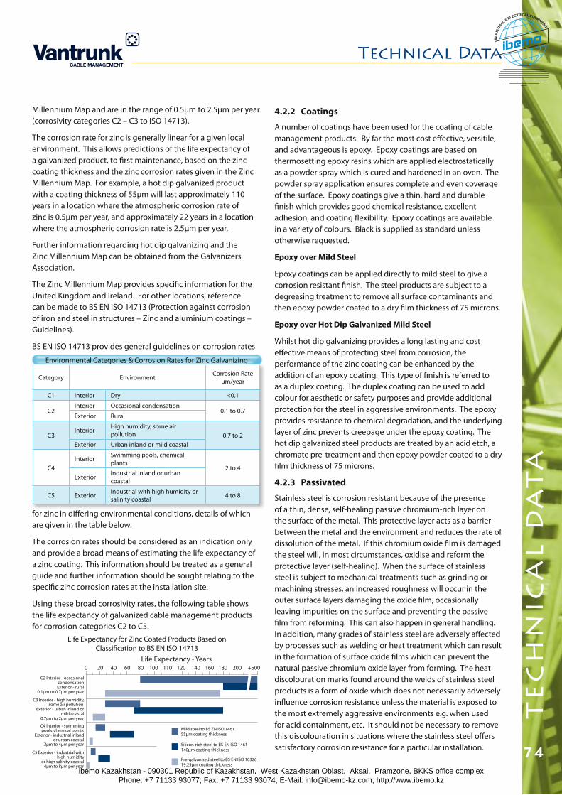
Technical Data
74
te
ch
nic
al
da
ta
4.2.2 Coatings
A number of coatings have been used for the coating of cable management products. By far the most cost effective, versitile, and advantageous is epoxy. Epoxy coatings are based on thermosetting epoxy resins which are applied electrostatically as a powder spray which is cured and hardened in an oven. The powder spray application ensures complete and even coverage of the surface. Epoxy coatings give a thin, hard and durable finish which provides good chemical resistance, excellent adhesion, and coating flexibility. Epoxy coatings are available in a variety of colours. Black is supplied as standard unless otherwise requested.
Epoxy over Mild Steel
Epoxy coatings can be applied directly to mild steel to give a corrosion resistant finish. The steel products are subject to a degreasing treatment to remove all surface contaminants and then epoxy powder coated to a dry film thickness of 75 microns.
Epoxy over Hot Dip Galvanized Mild Steel
Whilst hot dip galvanizing provides a long lasting and cost effective means of protecting steel from corrosion, the performance of the zinc coating can be enhanced by the addition of an epoxy coating. This type of finish is referred to as a duplex coating. The duplex coating can be used to add colour for aesthetic or safety purposes and provide additional protection for the steel in aggressive environments. The epoxy provides resistance to chemical degradation, and the underlying layer of zinc prevents creepage under the epoxy coating. The hot dip galvanized steel products are treated by an acid etch, a chromate pre-treatment and then epoxy powder coated to a dry film thickness of 75 microns.
4.2.3 Passivated
Stainless steel is corrosion resistant because of the presence of a thin, dense, self-healing passive chromium-rich layer on the surface of the metal. This protective layer acts as a barrier between the metal and the environment and reduces the rate of dissolution of the metal. If this chromium oxide film is damaged the steel will, in most circumstances, oxidise and reform the protective layer (self-healing). When the surface of stainless steel is subject to mechanical treatments such as grinding or machining stresses, an increased roughness will occur in the outer surface layers damaging the oxide film, occasionally leaving impurities on the surface and preventing the passive film from reforming. This can also happen in general handling. In addition, many grades of stainless steel are adversely affected by processes such as welding or heat treatment which can result in the formation of surface oxide films which can prevent the natural passive chromium oxide layer from forming. The heat discolouration marks found around the welds of stainless steel products is a form of oxide which does not necessarily adversely influence corrosion resistance unless the material is exposed to the most extremely aggressive environments e.g. when used for acid containment, etc. It should not be necessary to remove this discolouration in situations where the stainless steel offers satisfactory corrosion resistance for a particular installation.
Category Environment Corrosion Rate μm/year
C1 Interior Dry <0.1
C2Interior Occasional condensation
0.1 to 0.7Exterior Rural
C3Interior High humidity, some air
pollution 0.7 to 2Exterior Urban inland or mild coastal
C4Interior Swimming pools, chemical
plants2 to 4
Exterior Industrial inland or urban coastal
C5 Exterior Industrial with high humidity or salinity coastal 4 to 8
Environmental Categories & Corrosion Rates for Zinc Galvanizing
Life Expectancy for Zinc Coated Products Based on Classification to BS EN ISO 14713
Mild steel to BS EN ISO 146155µm coating thickness
Silicon-rich steel to BS EN ISO 1461140µm coating thickness
Pre-galvanised steel to BS EN ISO 1032619.25µm coating thickness
C3 Interior - high humidity, some air pollution
Exterior - urban inland or mild coastal
0.7µm to 2µm per year
C2 Interior - occasional condensationExterior - rural
0.1µm to 0.7µm per year
C5 Exterior - industrial with high humidity
or high salinity coastal4µm to 8µm per year
C4 Interior - swimming pools, chemical plants
Exterior - industrial inland or urban coastal
2µm to 4µm per year
0 4020 8060 110100 140120 180160 +500200
Millennium Map and are in the range of 0.5μm to 2.5μm per year (corrosivity categories C2 – C3 to ISO 14713).
The corrosion rate for zinc is generally linear for a given local environment. This allows predictions of the life expectancy of a galvanized product, to first maintenance, based on the zinc coating thickness and the zinc corrosion rates given in the Zinc Millennium Map. For example, a hot dip galvanized product with a coating thickness of 55μm will last approximately 110 years in a location where the atmospheric corrosion rate of zinc is 0.5μm per year, and approximately 22 years in a location where the atmospheric corrosion rate is 2.5μm per year.
Further information regarding hot dip galvanizing and the Zinc Millennium Map can be obtained from the Galvanizers Association.
The Zinc Millennium Map provides specific information for the United Kingdom and Ireland. For other locations, reference can be made to BS EN ISO 14713 (Protection against corrosion of iron and steel in structures – Zinc and aluminium coatings – Guidelines).
BS EN ISO 14713 provides general guidelines on corrosion rates
Life Expectancy - Years
for zinc in differing environmental conditions, details of which are given in the table below.
The corrosion rates should be considered as an indication only and provide a broad means of estimating the life expectancy of a zinc coating. This information should be treated as a general guide and further information should be sought relating to the specific zinc corrosion rates at the installation site.
Using these broad corrosivity rates, the following table shows the life expectancy of galvanized cable management products for corrosion categories C2 to C5.
ibemo Kazakhstan - 090301 Republic of Kazakhstan, West Kazakhstan Oblast, Aksai, Pramzone, BKKS office complex Phone: +7 71133 93077; Fax: +7 71133 93074; E-Mail: [email protected]; http://www.ibemo.kz
ibemoIND
USTR
IA
L & ELECTRICAL EQUIPMENT
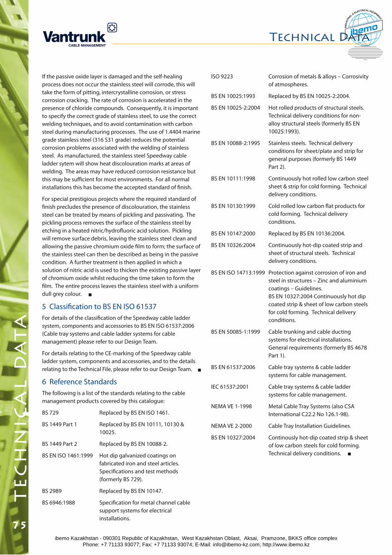
If the passive oxide layer is damaged and the self-healing process does not occur the stainless steel will corrode, this will take the form of pitting, intercrystalline corrosion, or stress corrosion cracking. The rate of corrosion is accelerated in the presence of chloride compounds. Consequently, it is important to specify the correct grade of stainless steel, to use the correct welding techniques, and to avoid contamination with carbon steel during manufacturing processes. The use of 1.4404 marine grade stainless steel (316 S31 grade) reduces the potential corrosion problems associated with the welding of stainless steel. As manufactured, the stainless steel Speedway cable ladder sytem will show heat discolouration marks at areas of welding. The areas may have reduced corrosion resistance but this may be sufficient for most environments. For all normal installations this has become the accepted standard of finish.
For special prestigious projects where the required standard of finish precludes the presence of discolouration, the stainless steel can be treated by means of pickling and passivating. The pickling process removes the surface of the stainless steel by etching in a heated nitric/hydrofluoric acid solution. Pickling will remove surface debris, leaving the stainless steel clean and allowing the passive chromium oxide film to form; the surface of the stainless steel can then be described as being in the passive condition. A further treatment is then applied in which a solution of nitric acid is used to thicken the existing passive layer of chromium oxide whilst reducing the time taken to form the film. The entire process leaves the stainless steel with a uniform dull grey colour.
5 Classification to BS EN ISO 61537For details of the classification of the Speedway cable ladder system, components and accessories to BS EN ISO 61537:2006 (Cable tray systems and cable ladder systems for cable management) please refer to our Design Team.
For details relating to the CE-marking of the Speedway cable ladder system, components and accessories, and to the details relating to the Technical File, please refer to our Design Team.
6 Reference StandardsThe following is a list of the standards relating to the cable management products covered by this catalogue:
BS 729 Replaced by BS EN ISO 1461.
BS 1449 Part 1 Replaced by BS EN 10111, 10130 & 10025.
BS 1449 Part 2 Replaced by BS EN 10088-2.
BS EN ISO 1461:1999 Hot dip galvanized coatings on fabricated iron and steel articles. Specifications and test methods (formerly BS 729).
BS 2989 Replaced by BS EN 10147.
BS 6946:1988 Specification for metal channel cable support systems for electrical installations.
ISO 9223 Corrosion of metals & alloys – Corrosivity of atmospheres.
BS EN 10025:1993 Replaced by BS EN 10025-2:2004.
BS EN 10025-2:2004 Hot rolled products of structural steels. Technical delivery conditions for non- alloy structural steels (formerly BS EN 10025:1993).
BS EN 10088-2:1995 Stainless steels. Technical delivery conditions for sheet/plate and strip for general purposes (formerly BS 1449 Part 2).
BS EN 10111:1998 Continuously hot rolled low carbon steel sheet & strip for cold forming. Technical delivery conditions.
BS EN 10130:1999 Cold rolled low carbon flat products for cold forming. Technical delivery conditions.
BS EN 10147:2000 Replaced by BS EN 10136:2004.
BS EN 10326:2004 Continuously hot-dip coated strip and sheet of structural steels. Technical delivery conditions.
BS EN ISO 14713:1999 Protection against corrosion of iron and steel in structures – Zinc and aluminium coatings – Guidelines. BS EN 10327:2004 Continuously hot dip coated strip & sheet of low carbon steels for cold forming. Technical delivery conditions.
BS EN 50085-1:1999 Cable trunking and cable ducting systems for electrical installations. General requirements (formerly BS 4678 Part 1).
BS EN 61537:2006 Cable tray systems & cable ladder systems for cable management.
IEC 61537:2001 Cable tray systems & cable ladder systems for cable management.
NEMA VE 1-1998 Metal Cable Tray Systems (also CSA International C22.2 No 126.1-98).
NEMA VE 2-2000 Cable Tray Installation Guidelines.
BS EN 10327:2004 Continously hot-dip coated strip & sheet of low carbon steels for cold forming. Technical delivery conditions.
Technical Datat
ec
hn
ica
l d
at
a
75ibemo Kazakhstan - 090301 Republic of Kazakhstan, West Kazakhstan Oblast, Aksai, Pramzone, BKKS office complex Phone: +7 71133 93077; Fax: +7 71133 93074; E-Mail: [email protected]; http://www.ibemo.kz
ibemoIND
USTR
IA
L & ELECTRICAL EQUIPMENT
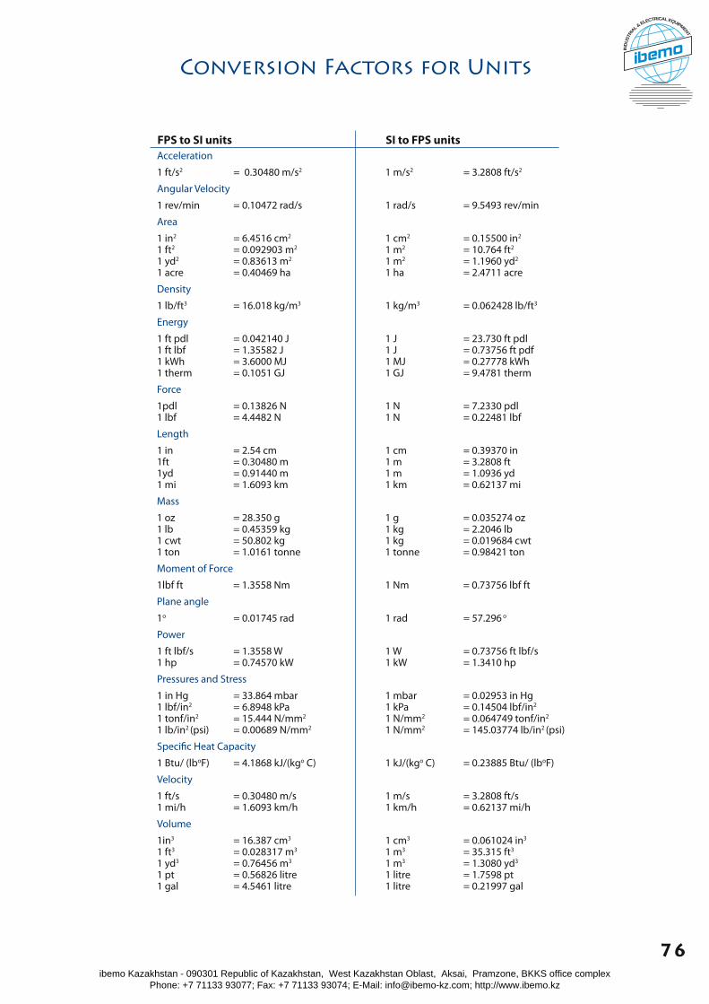
Conversion Factors for Units
Acceleration
1 ft/s2 = 0.30480 m/s2 1 m/s2 = 3.2808 ft/s2
Angular Velocity
1 rev/min = 0.10472 rad/s 1 rad/s = 9.5493 rev/min
Area
1 in2 = 6.4516 cm2 1 cm2 = 0.15500 in2
1 ft2 = 0.092903 m2 1 m2 = 10.764 ft2
1 yd2 = 0.83613 m2 1 m2 = 1.1960 yd2
1 acre = 0.40469 ha 1 ha = 2.4711 acre
Density
1 lb/ft3 = 16.018 kg/m3 1 kg/m3 = 0.062428 lb/ft3
Energy
1 ft pdl = 0.042140 J 1 J = 23.730 ft pdl1 ft lbf = 1.35582 J 1 J = 0.73756 ft pdf1 kWh = 3.6000 MJ 1 MJ = 0.27778 kWh1 therm = 0.1051 GJ 1 GJ = 9.4781 therm
Force
1pdl = 0.13826 N 1 N = 7.2330 pdl1 lbf = 4.4482 N 1 N = 0.22481 lbf
Length
1 in = 2.54 cm 1 cm = 0.39370 in1ft = 0.30480 m 1 m = 3.2808 ft1yd = 0.91440 m 1 m = 1.0936 yd1 mi = 1.6093 km 1 km = 0.62137 mi
Mass
1 oz = 28.350 g 1 g = 0.035274 oz1 lb = 0.45359 kg 1 kg = 2.2046 lb1 cwt = 50.802 kg 1 kg = 0.019684 cwt1 ton = 1.0161 tonne 1 tonne = 0.98421 ton
Moment of Force
1lbf ft = 1.3558 Nm 1 Nm = 0.73756 lbf ft
Plane angle
1o = 0.01745 rad 1 rad = 57.296 o
Power
1 ft lbf/s = 1.3558 W 1 W = 0.73756 ft lbf/s1 hp = 0.74570 kW 1 kW = 1.3410 hp
Pressures and Stress
1 in Hg = 33.864 mbar 1 mbar = 0.02953 in Hg1 lbf/in2 = 6.8948 kPa 1 kPa = 0.14504 lbf/in2
1 tonf/in2 = 15.444 N/mm2 1 N/mm2 = 0.064749 tonf/in2
1 lb/in2 (psi) = 0.00689 N/mm2 1 N/mm2 = 145.03774 lb/in2 (psi)
Specific Heat Capacity
1 Btu/ (lboF) = 4.1868 kJ/(kgo C) 1 kJ/(kgo C) = 0.23885 Btu/ (lboF)
Velocity
1 ft/s = 0.30480 m/s 1 m/s = 3.2808 ft/s1 mi/h = 1.6093 km/h 1 km/h = 0.62137 mi/h
Volume
1in3 = 16.387 cm3 1 cm3 = 0.061024 in3
1 ft3 = 0.028317 m3 1 m3 = 35.315 ft3
1 yd3 = 0.76456 m3 1 m3 = 1.3080 yd3
1 pt = 0.56826 litre 1 litre = 1.7598 pt1 gal = 4.5461 litre 1 litre = 0.21997 gal
FPS to SI units SI to FPS units
76ibemo Kazakhstan - 090301 Republic of Kazakhstan, West Kazakhstan Oblast, Aksai, Pramzone, BKKS office complex Phone: +7 71133 93077; Fax: +7 71133 93074; E-Mail: [email protected]; http://www.ibemo.kz
ibemoIND
USTR
IA
L & ELECTRICAL EQUIPMENT