SP PEÇAS DESPIECE ARE P AR
44
DESPIECE DESPIECE PEÇAS PEÇAS SP SP ARE P ARE P AR AR TS TS www.benza.es E2400 Modelo Motor Alternador Chasis Modêlo Motor Alternador Chassis Model Engine Alternator Chassis GENERADORES - GERADORES - GENERA GENERADORES - GERADORES - GENERA T T ORS ORS
Transcript of SP PEÇAS DESPIECE ARE P AR

DESPIECEDESPIECEPEÇASPEÇASSPSPARE PARE PARARTSTS
www.benza.es
E2400Modelo
Motor
Alternador
Chasis
Modêlo
Motor
Alternador
Chassis
Model
Engine
Alternator
Chassis
GE
NE
RA
DO
RE
S -
GE
RA
DO
RE
S -
GE
NE
RA
GE
NE
RA
DO
RE
S -
GE
RA
DO
RE
S -
GE
NE
RA
TTO
RS
OR
S


4265
170
ALTERNADORES - ALTERNATORSLSA 32 - Monofásico/single phaseInformation de puesta en servicio y mantenimiento
Installation and maintenance
Réf. 1326 - 033 / a - 10.92

AlternatorLSA 32, 2 Pole
AlternadorLSA 32, 2 Polos
Estimado Cliente,
Este manual se utiliza para el alternador LEROY-SOMER «PARTNER»,que Usted acaba de adquirir.
Ultimo de una nueva generación de alternadores,«PARTNER» se beneficia de la experiencia
de uno de los más importantes constructores mundiales,utilizando una tecnología de vanguardia a nivel de automatización
de los materiales seleccionados y de un control de calidad riguroso.
Apreciamos su elección y deseamos atraer su atención en lo que respectaal contenido de este manual de mantenimiento.
En efecto, el respeto de algunos puntos importantesdurante la instalación, el uso y el mantenimiento de su alternador
le asegurará un funcionamiento sin problemasdurante largos años.
LEROY-SOMER ALTERNADOR
Dear Customer,
As one of the world's leading alternator manufacturerscombining up to the minute technology in design and manufacturing facilities
with a high standard of quality control,we are pleased to introduce you
to our latest generation of alternators «PARTNER».
We ask you to carefully read and followthe information given in this manual on installation and adjustment so as
to enable you to enjoy many years of care-free and dependable operation.
Yours
«LEROY-SOMER» alternator.

SUMARIO
1 - Generalidades1 - Características 42 - Utilización en carga 4
2 - Esquemas de principio1 - Monofásico 4 hilos 52 - Monofásico 3 hilos con carga batería 53 - Características de los componentes 5
3 - Operación de montaje y desmontaje1 - Instrucciones de montaje 62 - Instrucciones de desmontaje 63 - Alternador bipalier 7 Acoplamiento polea-correa4 - Almacenamiento - Situación 75 - Herramientas mecánicas y eléctricas minimas 7
4 - Puesta en servicio 7
5 - Diagnosis de averías 8 - 9
6 - Como efectuar los tests eléctricos1 - Medida de resistencias de los bobinados 102 - Medidas de los diodos 103 - Medida del condensador 11
7 - Nomenclatura 12
8 - Repuestos A quien dirigirse ? 13
INDEX
1 - General1 - Characteristics 42 - Normal operating conditions 4
2 - Wiring diagrams1 - Singlephase 4 wires 52 - Singlephase 3 wires + 12/24 DC 53 - Characteristics of components 5
3 - Disassembly and reassembly1 - Assembly instructions 62 - Disassembly instructions 63 - Two bearing alternators 7 Belt driven4 - Storage location 75 - Minimum tools required 7
4 - Starting up 7
5 - Fault finding 8-9
6 - Testing of components1 - Measurement of resistance of the various coils 102 - Checking the diodes 103 - Checking the capacitor 11
7 - Parts lists 12
8 - Spare parts Suppliers addresses 13
AlternatorLSA 32, 2 Pole
AlternadorLSA 32, 2 Polos
3

1 - GENERALIDADES1.1 - CaracterísticasAlternador PARTNER LSA 32 monofásico, autoexcitado,sin anillos ni escobillas, compound, excitación por con-densador, sin regulador.
Conforme a las normas : CSA, NEMA, VDE, BSS, CEI.
Refrigeración : Turbina interna, aspiración al ladoopuesto al acoplamiento.
Protección : IP 23 M, clase F/H.
Velocidad : 3000 a 3600 rpm, según la frecuencia.Utilización en ambos sentidos de rotación. Por debajodel 40 % de la velocidad nominal, no hay tensión.
1.2 - Utilización en cargaEn uso continuo : S1 sobre carga resistiva para tempe-ratura ≤ 40 grados C y altitud ≤ 1000 m, el alternador estágarantizado para una duración de vida del orden de2000 000 horas de bobinado.
En uso de emergencia : S2, sobrecarga + 10 % durante1 hora. Duración de vida de 10 000 horas del bobinado.
En uso máximo : S6, sobrecarga ocasional + 20 % du-rante algunos minutos (arranque de motores). Duraciónde vida del bobinado 3000 horas.
Tensión : monofásica, 4 hilos reconectables en tensiónbaja o alta.
Opción monofásica : 3 hilos no reconectables en ten-síon baja, con salidas de hilos suplementarios 12 V y 24 Vcableadas desde el puente rectificador para carga de ba-tería cuya intensidad de carga corresponde a la intensi-dad nominal del alternador.
1 - GENERAL1.1 - CharacteristicsPARTNER LSA 32 Alternator, single-phase, self exciting,brushless. Excitation by capacitor without regulator(A.V.R.).
Conforms to : CSA, NEMA, VDE, BSS, CEI.
Cooling : internal fan, air entry non drive end.
Protection : IP 23 M, class F/H
Speed : 3000 or 3600 rpm depending on the frequency.
Rotation : clock wise or anticlock wise. Below 40 % ofnominal speed, non voltage output.
1.2 - Normal operation conditionsContinuous duty : S1 - unity PF load and for ambianttemperature ≤ 40° C and altitude ≤ 1000 m, your alterna-tor winding is designed for a life of 20.000 hours.
As an emergency supply : S2 - over load + for 1 hour -life of winding = 10 000 hours.
Maximum service : S6 maximum intermittent duty ie.20 % of S1 rating in line with engine curves. Life of win-ding 3000 hours.
Voltage : single phase 4 wires reconnectable for high orlow voltage.
Options : single phase non reconnectable 3 wires system low voltage, with supplementary 12 V and 24 V DCoutput through a rectifier bridge for battery charging.
AlternatorLSA 32, 2 Pole
AlternadorLSA 32, 2 Polos
Tensión alta 220 o 240 V
Tensión baja 110 o 120 V
TIPO IA carga batería
LSA 32.1 L4 4
LSA 32.1 L5 6
LSA 32.1 L9 8
LSA 32.1 L10 10
High voltage 220 or 240
Low voltage 110 or 120
TYPE IA battery charge
LSA 32.1 L4 4
LSA 32.1 L5 6
LSA 32.1 L9 8
LSA 32.1 L10 10
4

ROTOR Diodo ESTATOR
D C
Z1 - Blanco - White
Fase auxiliarAuxiliary phase
Z2 - Marrón - Brown
220/240 V
Alta tensiónHigh voltage
U1
T1
U2
T2
U5
T3
U6
T4
L1 L2
VerdeGreen
RojoRed
U2T2
U1T1
NegroBlack
AmarilloYellow
U5T3
U6T4
U6
T4
U2
T2
U5
T3
U1
T1
L1 L2110/120 V
PrincipalesbobinadesMain windings
Tensión bajaLow voltage
ROTOR Diodo ESTATOR
D C
T8 - Blanco - White
Fase auxiliarAuxiliary phase
T5 - Marrón - Brown
VerdeGreen
RojoRed
U2T2
U1T1
NegroBlack
AmarilloYellow
U5T3
U6T4
AzulBlue
AzulBlue
U3 U4
+12+240
U3 U4
Puente rectificador monofásicoD.C. rectifier bridge - single phase
2 - ESQUEMAS DE PRINCIPIO2.1 - Monofásico 4 hilos
2.2 - Monofásico 3 hilos con carga batería
2-3 Características de los componentes 110/220 V - 50 Hz
2 - WIRING DIAGRAMS2.1 - Single phase 4 wires
2.2 Single phase 3 wires + 12/24 V - DC
2.3 - Characteristics of components 120/240 V - 60 Hz
AlternatorLSA 32, 2 Pole
AlternadorLSA 32, 2 Polos
Tensión Salida Conexión
L1 L2
Baja U2 U6 U1 U5
Alta U1 U6 U2 U5
Voltage Output To link (connect)
L1 L2
Low T2 T4 T1 T3
High T1 T4 T2 T3
Tensión Conexión
L1 L2
Alta U1 U6 U2 U5
+ enchufe U3 U4
Salida Voltage To link (connect)
L1 L2
High T1 T4 T2 T3
+ Lead For rectifier U3 U4
Output
Tipos Fase Fase
T. alta auxil.
LSA 32.1 L4 6.3 25.2 4.9 0.9 8
LSA 32.1 L5 3.4 12.2 5.6 1.1 12
LSA 32.1 L9 2.1 7.2 6.8 1.3 16
LSA 32.1 L10 2 7.7 6.9 1.33 16
Resistencias ΩRotor
Condens.450 VMF C
DiodosCantid. 2
D
6 A1000 Vrápido
Types High V. Auxil.
phase phase
LSA 32.1 L4 5 14 4.9 0.9 8
LSA 32.1 L5 2.8 9.3 5.6 1.1 12
LSA 32.1 L9 1.7 5.2 6.8 1.3 16
LSA 32.1 L10 1.6 5.9 6.9 1.33 16
Resistance in ohmRotor
Capacitor450 VMF C
DiodesQty. 2
D
6 A1000 Vspeedy
5

3 - OPERACIÓN DE MONTAJE Y DESMONTAJE
DISASSEMBLY - REASSEMBLY
3.1 - Instrucciones de montaje- Assembly instructions
1 - Colocar la tapa en el motor, par de ajuste aconsejado :2,2 mkg. (Fig.1)
Mount the flange on the engine recommended tor-que : 2,2 mkg. (Fig.1)
2 - Montar el conjunto ESTATOR / ROTOR y fijarlo a los4 tornillos sobre la tapa delantera. Par de ajuste aconse-jado : 0.9 mkg. (Fig.2)
Mount the STATOR / ROTOR to the flange fastenthe 4 bolts. Recommended torque : 0.9 mkg. (Fig.2)
3 - Fijar el rotor por el espárrago del inducido, par deajuste aconsejado : 1.6 a 1.7 mkg. (Fig.3)
Fasten the rotor by the rod recommended torque :1.6 to 1.7 mkg.Mount the top on the air inlet screen. (Fig.3)
3.2 - Instrucciones de desmontaje- Disassembly instructions
1 - Desatornillar los 4 tornillos de la tapa del estator.
Unscrew the fixing bolts of the stator frame to theflange mounted on the engine.
Sacar con precaución el conjunto estator.
Remove with care the stator frame.
2 - Desatornillar el espárrago del inducido del rotor. Utili-zar el mazo, soportando con una mano el rotor y gol-peando secamente con el mazo sobre un polo salientecon el fin de sacar el rotor del eje del motor. (Fig.4)
Unscrew the tie-rod from the drive-shaft. Using a hi-de mallet support the rotor in one hand and strike firmlyon one of the pole faces to loosen from the engineshaft. (Fig.4)
3 - Desatornillar los 4 tornillos de la tapa sobre el motor.(Fig.5)
Unscrew the 4 fixing screws of the flange from theengine. (Fig.5)
AlternatorLSA 32, 2 Pole
AlternadorLSA 32, 2 Polos
Fig. 1
Fig. 2 - 3
Fig. 4
Fig. 5
6

3.3 - Alternador bipalierAcoplamiento polea-correa : la bancada utilizada paratensar las correas tiene que colocarse antes de montarel alternador.Los tornillos de tensado deben ser aplicados unicamentesobre las partes metálicas y lógicamente dispuestos.Esfuerzo radial máximo : recomendado 850 N para una du-ración de vida del rodamiento delantero de 10 000 horas.- Rodamiento utilizado : 6204 - ZZ - HT-C3- Diámetro del eje : 24 mm- Longitud del eje : 50 mmSe aconseja seguir estrictamente las recomendacionesdel fabricante para las dimensiones de las correas y poleas.
3.4 - Almacenamiento - SituaciónAlmacenamiento : Evitar almacenar el alternador en lu-gar húmedo, polvoriento o sometido a la intemperie.Situación : Es necesario impedir, en la medida de lo po-sible, el reciclaje de aire caliente, teniendo cuidado conlos gases de escape.
3.5 - Herramientas mecánicasy eléctricas minimas
- Llave de tubo 10 mm- Llave de tubo 13 mm- Polímetro para control- Llave para tornillo 100 x 5 mm
4 - PUESTA EN SERVICIOPrimera puesta en servicio :Todos los alternadores LEROY-SOMER estan compro-bados sobre bancos de pruebas en fábrica. En cuanto elrégimen nominal del motor sea alcanzado (3120 rpm -52 Hz o 3720 rpm - 62 Hz) la tensión sera la nominal.En caso de valor erróneo, regular la velocidad del motorcon un cuenta-vueltas o con un frecuencímetro.
Placa de características : Ejemplo
Piezas de recambio aconsejadas :- 2 diodos (6A - 1000 V rápido)- 1 condensador (ver especif. p. 5)- 1 rodamiento (6204 - ZZ - HT - C3)- 1 tapa plástica superior equipada LSA 32-1-09 o LSA 32-1-10 (con 2 tomas).
3.3 - Two bearing alternatorBelt driven : Slide rails used for belt adjustment shouldbe accurately positioned before mounting the alternator.Adjustment bolts should be placed in contact only withmetal surfaces of alternator and judiciously distributed.Maximum radial force : 850 N for a bearing life 10 000hours.- Bearing used : 6204 - ZZ - HT C3- Diam. shaft : 24 mm- Length shaft : 50 mmFor belt and pulley sizes, the manufacturer's recomman-dations should be followed.
3.4 - Storage locationLocation : hot air from the alternator or engine exhaustmust be prevented from recycling to cooling air inlet.Storage : storing the alternator in damp or dirty areasshould at all time be avoided.
3.5 - Minimum tools required- Spanner ø 10 mm- Spanner ø 13 mm- Multimeter for control test- Screw driver 100 X 5 mm
4 - STARTING UPInitial operation :All alternators are tested in a Leroy-Somer factory andthe speed of the engine is adjusted to 3120 rpm for52 Hz and 3720 rpm for 62 Hz. At these nominal no loadspeeds the nominal voltage is obtained, in case of diffe-rent values being obtained on first operation, check engi-ne speed with a rev.counter or Hz.meter.
Name plate : Example
Spare parts advised :- 2 diodes (6A - 1000 V fast)- 1 capacitor (see specif. p. 5)- 1 bearing (6204 - ZZ - HT - C3- 1 equipped plastic top cover : LSA 32-1-09 or LSA 32-1-10 with 2 sockets.
AlternatorLSA 32, 2 Pole
AlternadorLSA 32, 2 Polos
SERVICIO POTENCIA TENSIÓN INTENSIDAD
Continuo 1,8 kVA 110/220 V 16,3 - 8,1 A
Emergencia 2 kVA 110/220 V 18,2 - 9,1 A
Maxi. 2,2 kVA 110/220 V 20 - 10 A
Cos. 1,0
LSA 32 L9 - MONOFÁSICO
ALTERNADORPARTNER
3000 min -1 50 Hz
DUTY POWER VOLTAGE AMPS
CONT. 2,2 kVA 120/240 V 18,3 - 9,2 A
St. by. 2,5 kVA 120/240 V 21 - 10,5 A
MAXI. 2,5 kVA 120/240 V 22 - 11 A
PF. 1
LSA 32 L9 - SINGLE PHASE
PARTNERALTERNATOR
3600 min -1 60 Hz
ENTRADA DEAIRE FRÍO
SALIDA DEAIRE CALIENTE
COOLINGINLET
HOT AIROUTLET
7

5 - DIAGNOSIS DE AVERÍAS1 - Sin carga
AlternatorLSA 32, 2 Pole
AlternadorLSA 32, 2 Polos
Anomalia Causa probable Operación a realizar
Ausencia de tensiónen el arranque
Pérdida del flujo remanente Conectar una batería de 4,5 Ven las bornas del condensador
Poner en carga el alternador y hacerlogirar un poco + rápido un instante.
Condensador defectuoso Cambiar el condensador (ver § 6-3)
Diodo rotor abierto oen cortocircuito
Cambiar los 2 diodos del rotor(ver § 6-2)
Cortocircuito del bobinado oconexiones aflojadas
Verificar las resistencias de los bobinados(según tabla) (ver § 2-3)
Tensión en vacíoinferior al 80 % detensión nominal
Velocidad del motor térmicodemasiado baja
Volver a elevar el motor térmico a3120 rpm o 3720 rpm en vacío(frecuencia alternador 52 Hz o 62 Hz).
1 diodo del rotor fuera de servicioo en cortocircuito
Cortocircuito parcial del bobinado
Cambiar los 2 diodos del rotor(ver § 6-2)
Verificar las resistencias de los bobinados(según tabla) (ver § 2-3)
2 - Con carga
Tensión válida en vacíoy demasiado baja en carga
1 diodo del rotor fuera de servicioo en cortocircuito
Cambiar los 2 diodos del rotor(ver § 6-2.1)
El motor térmico se viene abajoen velocidad
Quitar carga al alternador ; la cargaaplicada es demasiado elevada
El motor térmico está mal regulado :dirigirse al especialista del motor
Calentamiento excesivo Orificios de ventilación parcialmentetaponados
Desmontar y limpiar el estator
Tensión demasiadoalta en vacío
Velocidad del motor térmicodemasiado alta
Ajustar la velocidad del motor térmicoa 3120 rpm o 3720 rpm
8
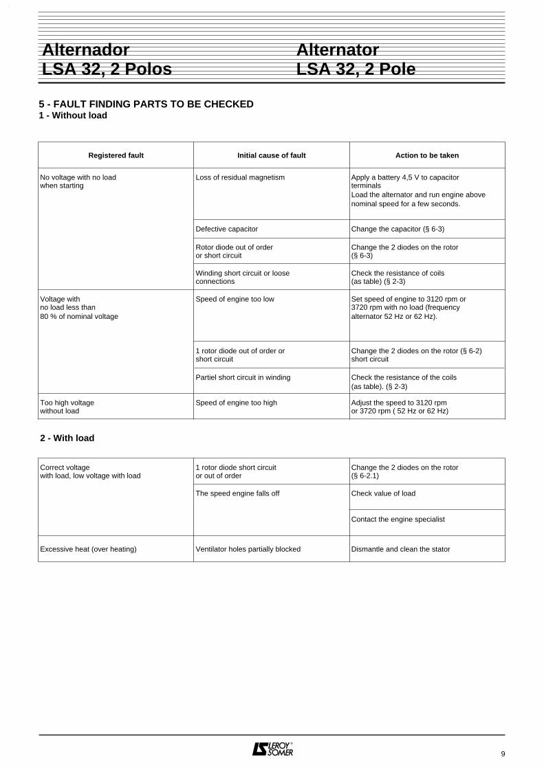
5 - FAULT FINDING PARTS TO BE CHECKED1 - Without load
AlternatorLSA 32, 2 Pole
AlternadorLSA 32, 2 Polos
Registered fault Initial cause of fault Action to be taken
No voltage with no loadwhen starting
Loss of residual magnetism Apply a battery 4,5 V to capacitorterminalsLoad the alternator and run engine abovenominal speed for a few seconds.
Defective capacitor Change the capacitor (§ 6-3)
Rotor diode out of orderor short circuit
Change the 2 diodes on the rotor(§ 6-3)
Winding short circuit or looseconnections
Check the resistance of coils(as table) (§ 2-3)
Voltage withno load less than80 % of nominal voltage
Speed of engine too low Set speed of engine to 3120 rpm or3720 rpm with no load (frequencyalternator 52 Hz or 62 Hz).
1 rotor diode out of order orshort circuit
Partiel short circuit in winding
Change the 2 diodes on the rotor (§ 6-2)short circuit
Check the resistance of the coils(as table). (§ 2-3)
Too high voltagewithout load
Speed of engine too high Adjust the speed to 3120 rpmor 3720 rpm ( 52 Hz or 62 Hz)
2 - With load
Correct voltagewith load, low voltage with load
1 rotor diode short circuitor out of order
Change the 2 diodes on the rotor(§ 6-2.1)
The speed engine falls off Check value of load
Contact the engine specialist
Excessive heat (over heating) Ventilator holes partially blocked Dismantle and clean the stator
9

6 - COMO EFECTUAR LOS TESTSELÉCTRICOS
6.1 - Medida de resistencias de los bobinados
Estator :- desatornillar los 4 tornillos de fijación de la tapa plásticasuperior,- desconectar los hilos del condensador para leer la re-sistencia de la fase auxiliar (p. 5).- desconectar los hilos del conector para leer la resisten-cia de la fase principal (p. 5).
Rotor :- proceder al desmontaje del estator (ver p. 6).- desoldar los hilos de los diodos para leer la resistenciade cada bobinado (p. 5).
6.2 - Medidas de los diodosa) Proceder de la misma manera que para la lectura dela resistencia del rotor desmontando la carcasa del esta-tor y desoldando un sólo lado de los diodos.b) Medir con el ohmetro en directo e inverso cada diodo.
6 - TESTING OF COMPONENTS
6.1 - Measurement of resistance of the various coils
Stator :- unscrew the top plastic cover.- disconnect the capacitor wires in order to check the re-sistance of the auxiliary phase (p. 5).- disconnect the capacitor 4 wires of the connector in or-der to check the resistance at the main winding (p. 5).
Rotor :- unscrew the 4 fixing screws of the stator frame to theflange mounted on the engine.- remove the complete frame (see p. 6).- unsolder the wires from the diodes in order to check theresistance of each winding (p. 5).
6.2 - Checking the diodesa) Follow the procedure for measuring the resistance atthe rotor winding as for as removal of the complete frameand unsolder only one side of the diodes.b) Check with ohmmeter in both directions.
AlternatorLSA 32, 2 Pole
AlternadorLSA 32, 2 Polos
CONDENSADORCAPACITOR
DIODODIODE
10

6.3 - Medida del condensadora) desatornillar los 4 tornillos de fijación de la tapa deplástico superior.b) desconectar los hilos del condensador y conectar elcondensador en una red alterna en serie con un interrup-tor y un amperímetro.
6.3 - Checking the capacitora) unscrew the top plastic coverb) disconnect the capacitor wires connect the capacitorto a mains voltage with a switch and an ammeter to readthe current (see table).
AlternatorLSA 32, 2 Pole
AlternadorLSA 32, 2 Polos
AlternadorAlternator
220/50 HzIA
240 V/60 HZIA
LSA 32.1 L4 8 0,55 0,72
LSA 32.1 L5 12 0,83 1,08
LSA 32.1 L9 16 1,1 1,44
LSA 32.1 L10 16 1,1 1,44
CondensadorCapacitor
MF
Estos valores pueden variar ± 10 %. The values are accurate to + 10 %.
CONDENSADORCAPACITOR
A
220 V/50 Hz240 V/60 Hz
INTERRUPTORSWITCH
11

7 - NOMENCLATURA 7 - PARTS
AlternatorLSA 32, 2 Pole
AlternadorLSA 32, 2 Polos
INTENSITÉ
TENSION
PUISSANCE
SERVICE
Continu
Stand-by
Maxi
COS. : 1
8,1 A
220 V
1,8 kVA
50 Hz
3000 min-1
MADE IN FRANCE
1 02
4 62
8
2 kVA
2,2 kVA
9,1 A
10 A220 V
220 V
1
2 / 24 V Continu 10A
IP 23M
ALTERNATEUR
LSA 321 L9
354266
48
4
15
265
214
170
110
20049
34950
1351
14
49
183 197
53
186
Ref. Cantid. Designación Rep Nbre Désignation1 1 Estator completo bobinado 1 1 Wound stator assembly4 1 Rotor completo bobinado 4 1 Wound rotor assembly13 1 Espárrago de inducido 13 1 Rod14 1 Tuerca 14 1 Nut15 1 Turbina 15 1 Fan22 1 Chaveta 22 1 Key30 1 Contrabrida 30 1 D.E bracket48 1 Tapa superior 48 1 Terminal box cover49 Tornillos 49 Screws50 1 Tapa inferior 50 1 Terminal box cover51 1 Chapa de entrada de aire 51 1 Air inlet screen53 1 Tapón 53 1 Top60 1 Rodamiento delantero 60 1 D.E bearing70 1 Rodamiento trasero 70 1 N.D.E bearing110 2 Diodo 110 2 Diode183 1 Condensador 183 1 Capacitor186 1 Soporte del condensador 186 1 Capacitor support197 1 Connector 197 1 Connector200 2 Toma monofásica 200 2 Single phase socket214 1 Puente rectificador 214 1 Rectifiers bridge265 1 Brida de acoplamiento 265 1 Coupling flange266 4 Tornillos de fijación 266 4 Screw284 1 Circlips 284 1 Circlip349 1 Junto "O ring" 349 1 Rubber "O ring"354 1 Arandela de apoyo 354 1 Washers412 1 Circlips 412 1 Circlip
12

8 - REPUESTOS A QUIEN DIRIGIRSE ?
A su proveedor habitual o a :
MOTEURS LEROY-SOMERUsine de Sillac16015 ANGOULÊME CEDEX FRANCE
Tél. : (33) 45 91 91 11Service SAT poste 2015Télex : 790 044 - Fax : 45 91 95 88Télétex : 45 91 87 84
Para evitar errores en la entrega de los repuestos, no ol-vidarse de indicar las informaciones anotadas en la placadescriptiva, sobre todo el tipo y número de la máquina ytambién el número de referencia de la pieza en la no-menclatura.
Para los alternadores monopalier precisar :- Brida : el número de SAE de la brida (el diámetro de
centrado, el número y el diámetro de los agujeros).- Disco : el número del disco o el diámetro exterior.
8 - SPARE PARTSSUPPLIERS ADDRESSES
Address enquiries and orders to :
MOTEURS LEROY-SOMERUsine de Sillac16015 ANGOULÊME CEDEX FRANCE
Tél. : (33) 45 91 91 11Service SAT poste 2015Télex : 790 044 - Fax : 45 91 95 88Télétex : 45 91 87 84
To ovoid errors on delivery of spare parts, all informationmarked on nameplates shall be furnished on parts or-ders, in particular model and serial number of the alter-nator. Also give the parts numbers from the parts lists.
When single bearing, indicate :- Flange : SAE Nr (bore diameter, number and diameter
of holes).- Disc : disc Nr or outside diameter.
AlternatorLSA 32, 2 Pole
AlternadorLSA 32, 2 Polos
INTENSITÉ
TENSION
PUISSANCE
SERVICE
Continu
Stand-by
Maxi
COS. : 1
8,1 A
220 V
1,8 kVA
50 Hz
3000 min-1
MADE IN FRANCE
1 02
4 62
8
2 kVA
2,2 kVA
9,1 A
10 A220 V
220 V
1
2 / 24 V Continu 10A
IP 23M
ALTERNATEUR
LSA 321 L9
354266
48
4
15
34950
1351
14
214
49
170
110
183 197
20049
53
3060
22284
412
186
13

Notas / Notes
14


MOTEURS LEROY-SOMER 16015 ANGOULEME CEDEX-FRANCE
Imprimerie MOTEURS LEROY-SOMERRC ANGOULEME B 671 820 223