Fundamentos termodinámicos de la bomba de calor:principios y ciclos termodinámicos
Upload
ruben-reyesCategory
view
235download
0description

Descripción modelo 41 El equipo modelo 410 intercambiadores térmicelementos intercambiada la unidad de alimencaliente con calefactor epuede ajustarse la tempcaliente mediante válvul Las temperaturas relevmediante indicadores dilos cuales se suministraPC.
· Unidad de alimentaci· Procesamiento de los· Tomas de agua con a Ensayos · Funcionamiento y com- Intercambiador térmico- Intercambiador térmico- Intercambiador térmico- Intercambiador térmico· Secuencias de la temp· Secuencias de la temp· Comparación mutua en
UUNNIIDDAADD DDEE IINNTTEERRCCAAMMBBIIAADDOORR TTÉÉRRMMIICCOO
0
representa una unidad de alimentación cerrada en sí misma para diferentes os. Para estudios y ensayos se dispone como accesorios de 4 diferentes
ores térmicos. Cada uno de estos intercambiadores térmicos puede conectarse tación mediante acoplamientos rápidos. Ésta contiene un depósito de agua léctrico, una bomba así como un panel de indicadores y mandos. En el mismo eratura del agua mediante un regulador eléctrico así como el flujo de agua fría y as mariposas.
antes se miden mediante elementos PTC y, como el caudal, se muestran gitales. Mediante la tarjeta de registro de los datos de medición y el software, n como accesorio (modelo 410.05), es viable el procesamiento de los datos en
ón para diferentes tipos de intercambiadores térmicos datos de medición en PC con el modelo 410.05 coplamiento rápido
portamiento funcional de intercambiadores térmicos: de tubo (modelo 410.01) de placas (modelo 410.02) de haz de tubos (modelo 410.03) de camisa doble (modelo 410.04) eratura en servicio de corriente continua eratura en servicio de contracorriente tre diferentes tipos de intercambiadores térmicos

UUNNIIDDAADD DDEE IINNTTEERRCCAAMMBBIIAADDOORR TTÉÉRRMMIICCOO
La ilustración muestra el elemento "Intercambiador térmico de tubo" 410.01 que puede adquirirse como accesorio
Especificación [1] Unidad de alimentación para 4 diferentes tipos de intercambiadores térmicos [2] Equipo de mesa, LxAnxAl 1000x600x300mm, 80kg[3] Depósito de agua de 10Ltr con calefactor de 3kW [4] Bomba máx. 540 Ltr/h, 25 m altura de elevación [5] Tomas de agua con acoplamiento rápido [6] Procesamiento en PC de los valores medidos con el modelo 410.05 [7] Indicación digital de la temperatura y caudal [8] Regulador electrónico de la temperatura 0..80°C [9]Mediación de la temperatura mediante elementos PTC - 40..150°C [10] 230V,~50Hz Datos técnicos Bomba Potencia máx. de transporte 540Ltr/h Altura de elevación máx. 25m Calefactor 3kW Termostato 0..80°C Caudal Parte fría, máx. 600Ltr/h Parte caliente, máx. 600Ltr/h
1 bastidor, 2 posición de montaje del intercambiador térmico, 3 recipiente para el agua de goteo, 4 indicadores de temperatura, 5 conmutación de la indicación agua fría/caliente, 6 válvula reguladora del agua caliente, 7 válvula reguladora del agua fría, 8 conexión para el registro de datos de medición, 9 indicador de caudal, 10 bomba On/Off, 11 regulador de temperatura, 12 calefactor On/Off, 13 indicador de advertencia depósito, 14 conexiones elemento térmico, 15 tomas de agua

UUNNIIDDAADD DDEE IINNTTEERRCCAAMMBBIIAADDOORR TTÉÉRRMMIICCOO
Esquema del proceso
La ilustración muestra el esquema de proceso de la instalación con unidad de intercambiador térmico conectada.
Dimensiones y pesos LxAnxAl: 1000 x 600 x 300 mm Peso: 80 kg Conexiones 230V,~ 50Hz Toma de agua fría, mínimo 500Ltr/h Volumen de suministro 1 unidad de alimentación, 1 instrucciones de ensayo

IINNTTEERRCCAAMMBBIIAADDOORR TTÉÉRRMMIICCOO DDEE TTUUBBOO MMoodd.. 441100..0011
Intercambiador térmico de tubo para conexión a la unidad de alimentación modelo 410 Descripción El intercambiador térmico se conecta a la unidad de alimentación modelo 410 mediante acoplamientos rápidos y se asegura mediante tornillos de mango en estrella. Sondas térmicas para medición de la temperatura de admisión y de evacuación se encuentran en las conexiones de alimentación del modelo 410. En el intercambiador térmico de tubo se encuentran 2 sondas térmicas adicionales para medición de la temperatura promedia en el intercambiador. En la unidad de alimentación se encuentran posibilidades de conexión para estos puntos adicionales de medición de la temperatura.
Especificación [1] Intercambiador térmico para conexión aunidad de alimentación modelo 410 [2]Conexión mediante acoplamientos rápidos [3]2 sondas térmicas adicionales para medición de la temperatura promedia Datos técnicos Superficie de transmisión térmica 20000mm² Dimensiones y pesos LxAnxAl: 400 x 230 110 mm Peso: aprox. 6 kg Volumen de suministro 1 intercambiador térmico
Ensayos · Funcionamiento y comportamiento funcional de un intercambiador térmico de tubo · Secuencia de la temperatura en servicio de corriente continua · Secuencia de la temperatura en servicio de contracorriente · Comparación con otros tipos de intercambiadores térmicos

Intercambiador térm Descripción El intercambiador térmrápidos y se asegura temperatura de admisió410. Ensayos · Funcionamiento y com· Secuencia de la temp· Secuencia de la temp· Comparación con otro
IINNTTEERRCCAAMMBBIIAADDOORR TTÉÉRRMMIICCOO DDEE PPLLAACCAASS MMoodd.. 441100..0022
ico de placas para conexión a unidad de alimentación modelo 410.02
ico se conecta a la unidad de alimentación modelo 410 mediante acoplamientos mediante tornillos de mango en estrella. Sondas térmicas para medición de la n y de evacuación se encuentran en las conexiones de alimentación de modelo
portamiento funcional de un intercambiador térmico de placas eratura en servicio de corriente continua eratura en servicio de contracorriente s tipos de intercambiadores térmicos
Especificación [1] Intercambiador térmico para conexión aunidad de alimentación modelo 410 [2]Conexión mediante acoplamientos rápidos [3]5 placas, cada una de 8000mm² Datos técnicos Superficie de intercambio térmico 40000mm² Dimensiones y pesos LxAnxAl: 400 x 230 110 mm Peso: aprox. 5 kg Volumen de suministro 1 intercambiador térmico

IINNTTEERRCCAAMMBBIIAADDOORR TTÉÉRRMMIICCOO DDEE HHAAZZ DDEE TTUUBBOOSS mmoodd.. 441100..0033
Intercambiador térmico de haz de tubos para conexión a unidad de alimentación modelo 410 Descripción El intercambiador térmico se conecta a la unidad de alimentación modelo 410 mediante acoplamientos rápidos y se asegura mediante tornillos de mango en estrella. Sondas térmicas para medición de la temperatura de admisión y de evacuación se encuentran en las conexiones de alimentación del modelo 410. El tubo de camisa del intercambiador térmico está fabricado de plástico transparente de forma que el haz de tubos está completamente visible. El uso de intercambiadores térmicos de haz de tubos está muy extendido en la industria.
Ensayos · Funcionamiento y comportamiento funcional de un intercambiador térmico de haz de tubos · Secuencia de la temperatura en servicio de corriente continua · Secuencia de la temperatura en servicio de contracorriente · Comparación con otros tipos de intercambiadores térmicos Especificación [1] Intercambiador térmico para conexión a unidad de alimentación modelo 410 [2]Conexión mediante acoplamientos rápidos [3]Camisa transparente de tubo, haz de tubos visible [4]7 haces de tubos Datos técnicos Superficie de intercambio térmico 20000mm²
Dimensiones y pesos LxAnxAl: 400 x 230 110 mm Peso: aprox. 7 kg
Volumen de suministro 1 intercambiador térmico

Intercambiador témodelo 410 Descripción El intercambiador térmrápidos y se asegura temperatura de admisió410. En el intercambadicionales para medictérmico está equipado ensayo. En la unidadadicionales de mediciótransparente de forma
Ensayos · Funcionamiento y code un intercambiador té· Secuencia de la temcorriente continua · Secuencia de la temcontracorriente · Comparación cointercambiadores térmi
Dimensiones y pesosLxAnxAl: 400 x 230 400Peso: aprox. 9 kg
IINNTTEERRCCAAMMBBIIAADDOORR TTÉÉRRMMIICCOO DDEE CCAAMMIISSAA DDOOBBLLEE MMoodd.. 441100..0044
rmico de camisa doble para conexión a unidad de alimentación
ico se conecta a la unidad de alimentación modelo 410 mediante acoplamientos mediante tornillos de mango en estrella. Sondas térmicas para medición de la n y de evacuación se encuentran en las conexiones de alimentación de modelo
iador térmico de tubo de camisa doble se encuentran 2 sondas térmicas ión de la temperatura promedia en el intercambiador. Además, el intercambiador con un agitador que garantiza una mejor distribución de la temperatura durante el de alimentación se encuentran posibilidades de conexión para estos puntos n de la temperatura y agitador. La cubierta superior de intercambiador térmico es que permite la vista total sobre el sector de operación.
mportamiento funcional rmico de camisa doble peratura en servicio de
peratura en servicio de
n otros tipos de cos
Especificación [1] Intercambiador térmico para conexión a unidad de alimentación modelo 410 [2]Conexión mediante acoplamientos rápidos [3]2 sondas térmicas adicionales para medición de la temperatura promedia [4]Sector de trabajo visible gracias a cubierta transparente Datos técnicos Superficie de intercambio térmico 40000mm²
mm
Volumen de suministro 1 intercambiador térmico

SSIISSTTEEMMAA DDEE RREEGGIISSTTRROO DDEE DDAATTOOSS mmoodd.. 441100..0055
Registro de los datos de medición para ensayos de termocambiador Descripción El sistema de registro de datos de medición para ensayos de termocambiador con modelo 410 se compone de una tarjeta de registro de los datos de medición potente con software coordinado especialmente. Los datos de medición pueden representarse online en un PC. Con iconos pueden seleccionarse los diferentes intercambiadores térmicos, tanto si los intercambiadores térmicos funcionan con corriente continua o contracorriente. Las secuencias de temperatura se representan en un diagrama x,y, se calculan y representan los valores derivados como las cantidades energéticas dadas o tomadas. Además el proyecto ofrece la memorización de datos así como su impresión. Especificación [1] Sistema de registro de datos de medición compuesto de tarjeta de registro de los datos de medición y software [2] Software adaptado especialmente a los ensayos con intercambiadores térmicos [3] 4 intercambiadores térmicos diferentes seleccionables [5] representable tanto como servicio de contracorriente como también de corriente continua
Datos técnicos Software ejecutable bajo Windows 95 Tarjeta de registro de los datos de medición Resolución 12bit, aparatos de palpación y de salida100kHz0... 20mA 16 entradas analógicas, 2 salidas analógicas 8 entradas digitales, 8 salidas digitales
Volumen de suministro 1 tarjeta de registro de datos de medición, 1 disquete con software

HHeeaatt TTrraannssffeerr SSyysstteemm FFlluuiidd BBeedd aanndd FFlluuiiddiissaattiioonn mmoodd.. 552255
Technical Description The tabletop unit model 525 Heat Transfer System Fluid Bed and Fluidisation is experimental unit which enables getting of visual and quantitative results related to the flow of air through both packed and a fluidised be of granular material. It also provides quantitative results related to heat transfer in a fluidised bed. The entire system features the following: • Demonstration panel on which components are mounted • Experimental glass column with filter and distribution chamber • Glass chamber provides a depth of 70 mm of granular material • Heat control system • Digital display to measure voltage, current and power of the heater • Flow meter to measure air flow through bed • Digital thermometers to measure the temperature of heater surface, air inlet and granular material • Digital indicators to measure pressure drop through the bed • Digital indicators to measure differential pressure across the orifice to measure high air flow • Safety contrivance The unit is suitable both for practical tuition at vocational training colleges and for laboratory experiments at universities and technical colleges.
1. Demonstration panel 2. Heater control 3. Indication panel, digital displays forTemperatures, Pressures and Heater’s power,voltage and current 4. Printed schematic diagram 5. Temperature sensor 6. Filter 7. High air flow orifice 8. Temperature sensor 9. Fluidised bed in glass chamber 10. Air flow float type flowmeter with regulating valve 11. Heater 12. Distribution chamber 13. Distributor 14. Translucent glass with neon light

HHeeaatt TTrraannssffeerr SSyysstteemm FFlluuiidd BBeedd aanndd FFlluuiiddiissaattiioonn mmoodd.. 552255
Process schematic diagram
1 Glas chamber 2 Distribution chamber 3. Temperature indicator 4. Pressure indicator 5. Differential pressure indicator 6. Filter 7. Distributer 8. Float-type flowmeter 9. High air flow orifice 10. External air supply 11. Heater 12. Power meter
Didactical topics / List of Experiments The range of experiments includes: • Observation of the behaviour in a fluidised bed and comparison with different materials • Measurement of air flow and pressure drop through a variety of granular materials, as packed and as fluidised beds. • Investigation of the effect of distributor design on bed behaviour • Investigation of the effect of
- Superficial velocity - Depth of immersion - Particle size
• On the surface heat transfer coefficient for hot surface in a fluidised bed • Demonstration of separation by particle size and density Technical Data Overall dimensions:
length 900 mm width 455 mm height 820 mm weight 65 kg power supply 230 V/ 50 Hz,10 A
compressed air from network

HHeeaatt TTrraannssffeerr SSyysstteemm FFlluuiidd BBeedd aanndd FFlluuiiddiissaattiioonn mmoodd.. 552255
Contents of Supply
1 pc. Basic unit of model 525 Heat Transfer System Fluid Bed and Fluidisation
1 box of Alumina beads (125 µm) 1 box of Alumina beads (320 µm) 1 pc. Instruction manual
Ancillary equipment
Ancillary equipment is recommended. It must be ordered separately.

IINNTTEERRCCAAMMBBIIAADDOORR DDEE CCAALLOORR DDEE CCOORRRRIIEENNTTEESS CCRRUUZZAADDAASS//PPCC mmoodd.. 661100
Descripción El intercambiador térmico concebido como equipo de mesa está conformado como canal de aire por el que se aspira el aire mediante un ventilador radial. El caudal se regula mediante una mariposa. La corriente de aire cruza por el elemento calefactor, el calor se transfiere directamente al aire que pasa. Se dispone de varios elementos intercambiables con los que, caso de disposición en "haz de tubo" puede variarse adicionalmente la posición de montaje. De esta forma pueden simularse diferentes módulos de tubos, respect., haces de tubos de lo que resulta un amplia variedad de ensayos. Sensores detectan la pérdida de presión por los correspondientes elementos, la temperatura del aire al entrar en el canal y directamente en el elemento calefactor. Los datos de medición se transmiten a un módulo de control e indicación en el que se muestran los valores medidos y con el que se regula la potencia de calefacción. Sobre todo, facilita la transmisión de los datos de medición a un PC. El suministro incluye la tarjeta de registro de los datos de medición y el software.
· Estructura esquematizada del ensayo para demostración de los principios básicos de la transmisión térmica · Procesamiento de los datos de medición en PC · De flexible aplicación como equipo de mesa · Extensas instrucciones de ensayo inclusive representación de los principios teóricos Ensayos · Estudio de los procesos de convección · Comparación de la transmisión térmica con diferentes elementos calefactores · Comparación mutua de diferentes elementos calefactores · Representación de la relación entre transmisión térmica, superficie de transmisión térmica y velocidad de la corriente (granulación de hulla)

IINNTTEERRCCAAMMBBIIAADDOORR DDEE CCAALLOORR DDEE CCOORRRRIIEENNTTEESS CCRRUUZZAADDAASS//PPCC mmoodd.. 661100
1 caja para el convertidor de presión, 2 ventilador, 3 tubuladura para medición de la presión, 4 soporte, 5 canal de aire, 6 elemento calefactor para medición de temperatura, 7 elemento calefactor "haz de tubo", 8 elemento calefactor "tubo nervado", 9 elemento calefactor "tubo", 10 mariposa, 11 módulo de indicación y control
Datos técnicos Ventilador Vmáx 780m³/h, potencia máx. 250W Velocidad máx. de la corriente: 12m/s Calefactor Potencia nominal 480W, tmáx: 200°C Superficie de calefacción Tubo y haz de tubos: 0,00464m² Tubo nervado: 0,17746m² Dimensiones y pesos LxAnxAl: 500 x 500 x 1425 mm Peso: aprox. 55 kg
Especificación [1]Equipo de mesa para ensayos con un intercambiador térmico de corriente cruzada [2]LxAnxAl 500x500x1425mm [3]Calentamiento de una corriente de aire mediante un elemento calefactor máx.200°C [4]Sección transversal de la corriente 120x120mm [5]Determinación de la temperatura mediante elementos térmicos -50..400°C [6]Ventilador: volumen de salida máx. 780m³/h; potencia máx. 250W [7]Elemento calefactor: potencia nominal 480W, limitación de la temperatura a 200°C [8]230V, 50Hz Conexiones 230V, 50Hz
Volumen de suministro 1 intercambiador térmico completamente montado, 2 elemento calefactor, 1 módulo de indicación y control, 1 tarjeta de registro de los datos de medición con software, 1 juego de accesorios, 1 instrucciones de ensayo

MMuullttii--PPuurrppoossee AAiirr DDuucctt aanndd HHeeaatt TTrraannssffeerr UUnniitt
Technical Description mod. 612 The Magister Technology Multi-Purpose Air Duct and Heat Transfer Unit model 612 facilitates an enclosed system equipped with industrial measuring components. The unit has been designed and equipped both for experimental testing of all major problem areas in heat transfer and airflow engineering. The unit provides a modular insulated rectangular wind tunnel which is subdivided in 5 sections, namely: the centrifugal fan with contractor section, the insulated air duct with inspection window and with pitot-static tube, the interchangeable test section, the movable air duct with inspection window and the inlet section with straightener. The air ducts have a cross section of approx. 150mm wide and 300mm high. The interchangeable test section can be replaced with the optional heat exchangers MODEL 612.01, MODEL 612.02 and MODEL 612.03. A wide range of heat transfer experiments can be carried out together with our MODEL 612.10 Hot Water Bench, MODEL 612.11 Cold Water Bench and MODEL 612.12 Refrigerant Condensing Unit. Combined temperature humidity sensors are fitted both upstream and downstream of the interchangeable test section. Additionally, pressure tapings are located close to the temperature/humidity sensors. The pressure tapings are connectable to the differential pressure transmitter. This enables measurement of the differential pressure over the individual heat exchanger. Pressure tapings along the air duct provide together with the optional mod. 525.01 Multi-tube swivelling water manometer the facility to measure pressure losses along the air duct. Four interconnected pressure tapings, one in the centre of each side of the inlet section, are provided to measure the average pressure. A second differential pressure transmitter is connected to these tapings to measure the flow rate. The control cabinet comprises digital displays for flow rate, temperature, humidity and differential pressure. in addition, a main switch, an emergency stop switch and a centrifugal-fan switch are installed. The centrifugal fan blows directly to atmosphere. The flow rate can be adjusted by using an adjustable throttle plate which is mounted at the discharge side of the fan. The air duct is mounted at the suction side of the centrifugal fan. The test rig is suitable both for practical tuition at vocational training colleges and for laboratory experiments at universities and technical colleges.
Details 1. Mobile frame 2. Control cabinet 3. Centrifugal fan 4. Air duct contractor section5. Insulated air duct 6. Inspection window 7. Pitot-static tube 8. Toggle type fastener
9. Interchangeable test section 10. Insulated air duct 11. Straightener 12. Differential pressure transmitter (flow measurement) 13. Inclined manometer 14. Differential pressure transmitter 15. Combined Temperature and humidity sensor 16. Movable air duct

Technical Data Overall dimensions: length width height weight power supply Rectangular air duct: length width height Centrifugal fan with drair velocity in duct. nominal speed power supply Inclined manometer: measuring range Combined temperaturemeasuring range, tempeoutput signal 0 - 10 V DCmeasuring range, rel. huoutput signal 1 - 9 V DCauxiliary power 24 V AC Differential pressure smeasuring range Pitot-static tube: resolution: range:
MMuullttii--PPuurrppoossee AAiirr DDuucctt aanndd HHeeaatt TTrraannssffeerr UUnniitt
2150 mm 750 mm 1560 mm 230 kg 230 V / 50 Hz
approx. 1400 mm (without contractor section) 150 mm 300 mm
ive motor: approx. 6 m/s 2900 rpm 230 V, 50 Hz
approx. 10 mbar
/ humidity sensor: rature 0 - 50 °C
midity 10 - 90 %
ensors: 0 - 20 mbar
1 mm 320 mm
MMuullttii--PPuurrppoossee AAiirr DDuucctt aanndd HHeeaatt TTrraannssffeerr UUnniitt
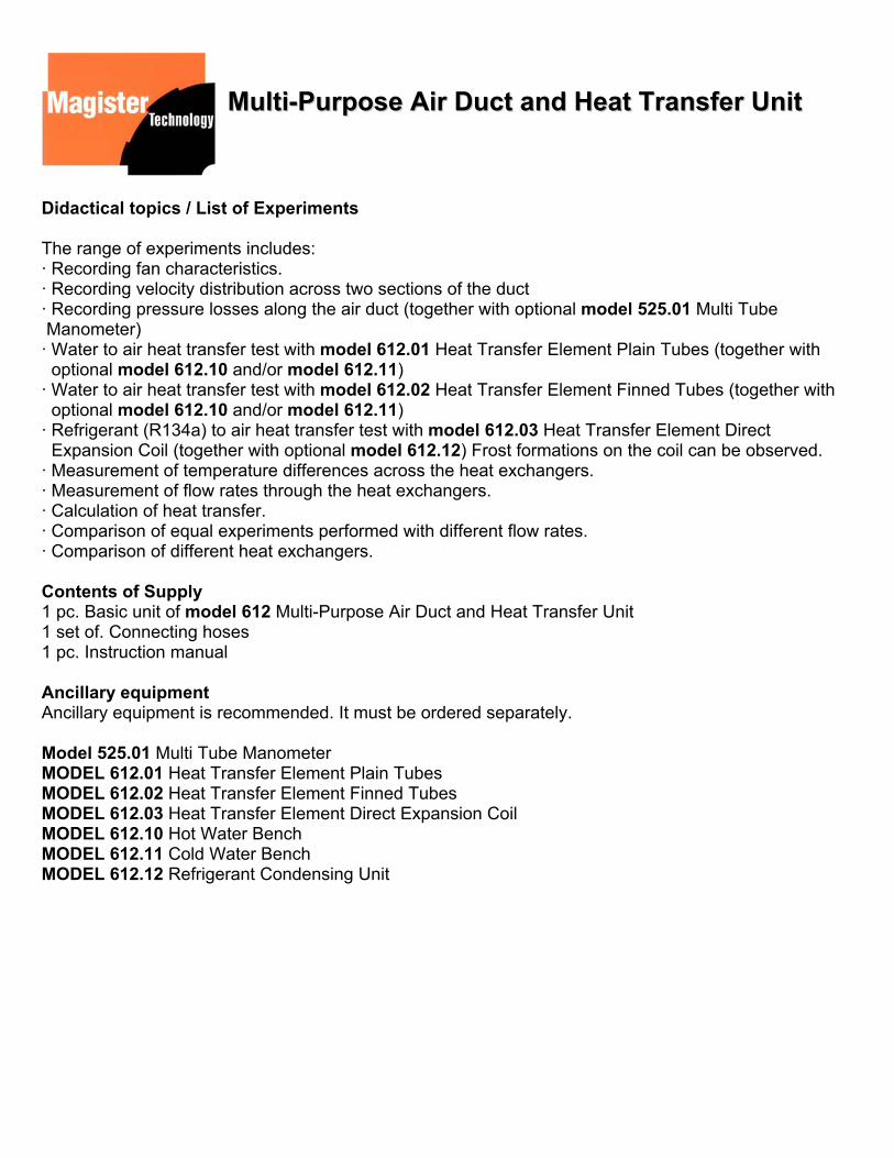
Didactical topics / List of Experiments The range of experiments includes: · Recording fan characteristics. · Recording velocity distribution across two sections of the duct · Recording pressure losses along the air duct (together with optional model 525.01 Multi Tube Manometer) · Water to air heat transfer test with model 612.01 Heat Transfer Element Plain Tubes (together with optional model 612.10 and/or model 612.11) · Water to air heat transfer test with model 612.02 Heat Transfer Element Finned Tubes (together with optional model 612.10 and/or model 612.11) · Refrigerant (R134a) to air heat transfer test with model 612.03 Heat Transfer Element Direct Expansion Coil (together with optional model 612.12) Frost formations on the coil can be observed. · Measurement of temperature differences across the heat exchangers. · Measurement of flow rates through the heat exchangers. · Calculation of heat transfer. · Comparison of equal experiments performed with different flow rates. · Comparison of different heat exchangers. Contents of Supply 1 pc. Basic unit of model 612 Multi-Purpose Air Duct and Heat Transfer Unit 1 set of. Connecting hoses 1 pc. Instruction manual Ancillary equipment Ancillary equipment is recommended. It must be ordered separately. Model 525.01 Multi Tube Manometer MODEL 612.01 Heat Transfer Element Plain Tubes MODEL 612.02 Heat Transfer Element Finned Tubes MODEL 612.03 Heat Transfer Element Direct Expansion Coil MODEL 612.10 Hot Water Bench MODEL 612.11 Cold Water Bench MODEL 612.12 Refrigerant Condensing Unit

HHeeaatt TTrraannssffeerr EElleemmeenntt PPllaaiinn TTuubbeess
Technical Description mod. 612.01 The Magister Technology series of heat transfer elements have been designed to study different types of heat exchangers. The heat transfer element model 612.01 facilities comprehensive experiments on a Plain Tubes heat exchanger. The heat exchanger has been designed for use with our model 612 Multi-Purpose Air Duct and Heat Transfer Unit. The element can be easily mounted into the air duct instead of the interchangeable test section with the help of eight toggle type fasteners. The element features: · Rectangular air duct of 150 mm wide and 300 mm high. · 33 plain copper pipes with an outer diameter of 16 mm and approx. 300 mm length. · The copper pipes are arranged in 3 banks of 11 pipes each. · The banks can be connected for single or parallel operation. · Temperature measurement at the water inlet and water outlet.
Hot or cold water supply can be used from our Hot Water Bench model 612.10 or from our Cold Water Bench model 612.11. The flowrate of the water can be measured by float type flowmeters, which are installed in the hot water bench and in the cold water bench. The flowrate of the air and the difference of the air temperature are measured in the air duct of model 612. The connection between the elements and the water supply can be done by special hoses, which are equipped with quick fastener fittings. The unit comes with a comprehensive instruction manual with student’s data sheets.
Technical Data Overall dimensions: length 290 mm width 330 mm height 560 mm weight 21 kg Contents of Supply 1 pc. Basic unit of model 612.01 Heat Transfer Element Plain Tubes 1 pc. Instruction manual

HHeeaatt TTrraannssffeerr EElleemmeenntt FFiinnnneedd TTuubbeess
Technical Description mod. 612.02 The Magister Technology Series of heat transfer elements has been designed to study different types of heat exchangers. The heat transfer element model 612.02 facilities comprehensive experiments on a Finned Tubes heat exchanger. The heat exchanger is meant to be used with our model 612 Multi-Purpose Air Duct and Heat Transfer Unit. The element can be easily installed on the air duct to replace the interchangeable test section with the help of eight toggle type fasteners. The element features: · Rectangular air duct of 150mm wide and 300mm high. · 6 finned copper pipes with an outer diameter of 16 mm and a length of approx. 300 mm. · Each pipe carries approx. 50 fins with an outer diameter of 34 mm · The copper pipes are arranged in 3 banks of 2 pipes each. · The banks can be connected for single or parallel operation. · Temperature measurement at the water inlet and water outlet. Hot or cold water can be supplied from our Hot Water Bench model 612.10 or our Cold Water Bench model 612.11.
The flow rate of the water can be measured by float-type flow-meters, which are installed in the hot water bench and in thecold water bench. The flow rate of the air and the difference inair temperature are measured in the air duct of model 612. The elements are connected to the water supply by specialhoses with quick fastener fittings. The unit comes with a comprehensive instruction manual withstudent’s data sheets. Technical Data Overall dimensions: length 290 mm width 330 mm height 560 mm weight 21 kg Contents of Supply 1 pc. Basic unit of model 612.02 Heat Transfer Element FinnedTubes 1 pc. Instruction manual
Technical Descript The Magister Technotypes of heat exchaexperiments on a Direuse with our model 6mounted into the air dfasteners. The element features: • Rectangular air duct • Finned air forced eva• Inspection window to• Water vapour can be on each side of the a• Temperature measur• Demonstrates Conde• Humidification of the The system is desigCondensing Unit modecan be produced with mdifference of the air tmodel 612. The corefrigerant supply and which are equipped witcomprehensive instruct Technical Data Overall dimensions: length 290 mm width 380 mm height 450 mm weight 21 kg Contents of Supply 1 pc. Basic unit of mExpansion Coil 1 pc. Air Obstruction Te1 pc. Instruction manua
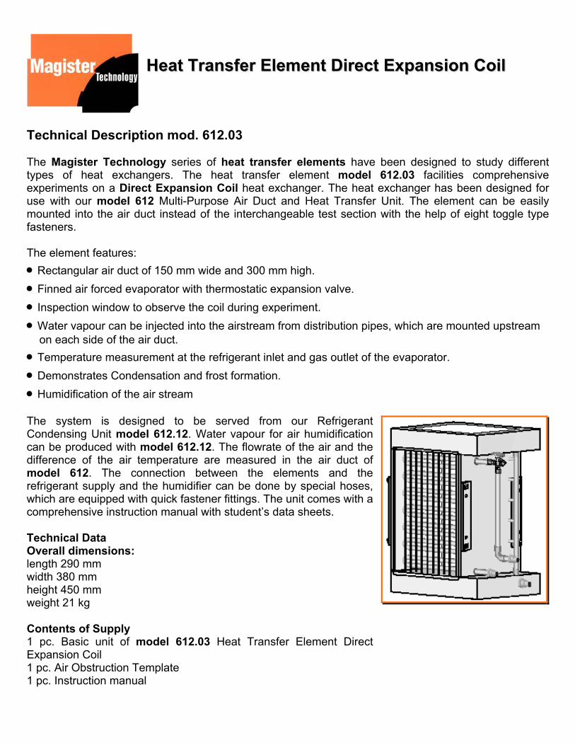
HHeeaatt TTrraannssffeerr EElleemmeenntt DDiirreecctt EExxppaannssiioonn CCooiill
ion mod. 612.03
logy series of heat transfer elements have been designed to study different ngers. The heat transfer element model 612.03 facilities comprehensive ct Expansion Coil heat exchanger. The heat exchanger has been designed for 12 Multi-Purpose Air Duct and Heat Transfer Unit. The element can be easily uct instead of the interchangeable test section with the help of eight toggle type
of 150 mm wide and 300 mm high. porator with thermostatic expansion valve. observe the coil during experiment. injected into the airstream from distribution pipes, which are mounted upstream ir duct. ement at the refrigerant inlet and gas outlet of the evaporator. nsation and frost formation. air stream
ned to be served from our Refrigerant l 612.12. Water vapour for air humidification odel 612.12. The flowrate of the air and the
emperature are measured in the air duct of nnection between the elements and the the humidifier can be done by special hoses, h quick fastener fittings. The unit comes with a ion manual with student’s data sheets.
odel 612.03 Heat Transfer Element Direct
mplate l

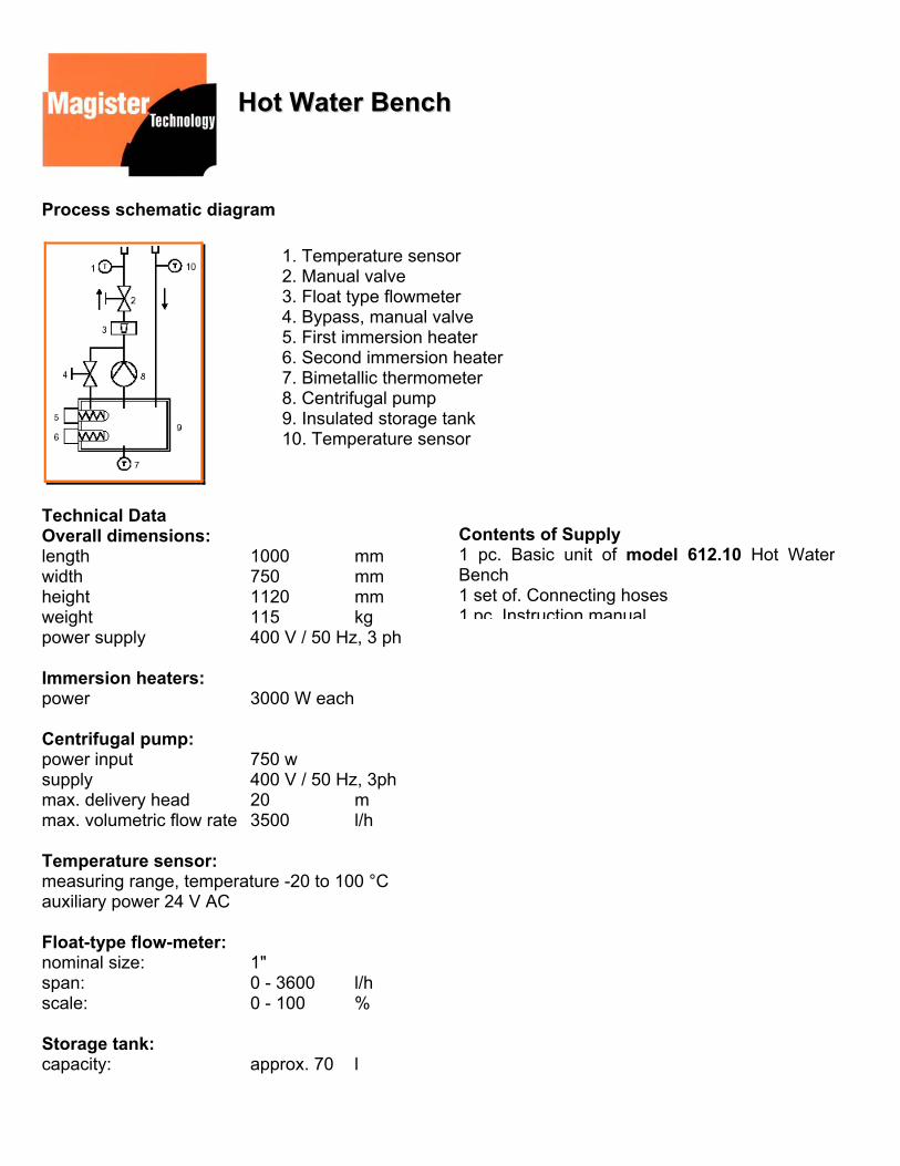
HHoott WWaatteerr BBeenncchh
Technical Description mod. 612.10 The Magister Technology Hot Water Bench model 612.10 has been specially designed to be use in conjunction with our model 612 Multi-Purpose Air Duct and Heat Transfer Unit. The unit enables hot-water supply for model 612.01 Heat Transfer Element Plain Tubes and model 612.02 Heat Transfer Element Finned Tubes. All components are selected according to industrial standards and installed in a mobile plastic coated steel frame. The control cabinet facilitates water-temperature measurement at the inlet and outlet points. A float-type flow-meter enables the measurement of the water’s flow-rate. The unit can easily be connected to the individual test equipment like model 612.01 and model 612.02 by using special hoses. A powerful centrifugal pump circulates water through the test equipment. The water in the storage tank can be heated with the two 3 kW electric immersion heaters. The heaters can be used as a two-stage heating system. The entire system comes with an extensive instruction manual.
Details 1. Mobile frame 2. Storage tank 3. Immersion heaters 4. Control cabinet with measuring instruments 5. Fittings for connection with the experiment
6. Temperature sensors 7. Manual valve 8. Float type flowmeter 9. Centrifugal pump 10. Bypass 11. Thermometer
HHoott WWaatteerr BBeenncchh
Process schematic diagram
1. Temperature sensor 2. Manual valve 3. Float type flowmeter 4. Bypass, manual valve 5. First immersion heater 6. Second immersion heater 7. Bimetallic thermometer 8. Centrifugal pump 9. Insulated storage tank 10. Temperature sensor
Technical Data
Contents of Supply 1 pc. Basic unit of model 612.10 Hot WaterBench 1 set of. Connecting hoses 1 pc Instruction manual
Overall dimensions: length 1000 mm width 750 mm height 1120 mm weight 115 kg power supply 400 V / 50 Hz, 3 ph Immersion heaters: power 3000 W each Centrifugal pump: power input 750 w supply 400 V / 50 Hz, 3ph max. delivery head 20 m max. volumetric flow rate 3500 l/h Temperature sensor: measuring range, temperature -20 to 100 °C auxiliary power 24 V AC Float-type flow-meter: nominal size: 1" span: 0 - 3600 l/h scale: 0 - 100 % Storage tank: capacity: approx. 70 l

CCoolldd WWaatteerr BBeenncchh
Technical Description mod. 612.11 The Magister Technology Cold Water Bench model 612.11 has been specially designed to be used in conjunction with our model 612 Multi-Purpose Air Duct and Heat Transfer Unit. The unit enables cold-water supply to model 612.01 Heat Transfer Element Plain Tubes and model 612.02 Heat Transfer Element Finned Tubes. All components are selected according to industrial standards and installed in a mobile plastic coated steel frame. The control cabinet facilitates water-temperature measurement at the inlet and outlet points. A float-type flow-meter enables the measurement of the water’s flow-rate. The unit can easily be connected to the individual test equipment like model 612.01 and model 612.02 by using special hoses. A powerful centrifugal pump circulates water through the test equipment. The water in the storage tank can be cooled with the water chillier. The evaporator is mounted into the storage tank for directly cooling of the water. The entire system comes with an extensive instruction manual.
Details 1. Mobile frame 2. Storage tank with evaporator 3. Heaters 4. Control cabinet with measuring instruments 5. Fittings for connection with the experiment 6. Temperature sensors
7. Manual valve 8. Float type flowmeter 9. Centrifugal pump 10. Bypass 11. Thermometer 12. Condenser 13. Compressor 14. Thermostatic expansion valve

CCoolldd WWaatteerr BBeenncchh
1. Temperature sensor 2. Manual valve 3. Pressure gauge suction side 4. Compressor 5. Low and high pressure controller 6. Pressure gauge discharge side 7. Air forced condenser 8. Liquid receiver 9. Drier / Filter 10. Flow indicator (sight glass) 11. Float type flowmeter 12. Temperature sensor 13. Bypass, manual valve 14. Centrifugal pump 15. Insulated water tank 16. Bimetallic thermometer 17. Evaporator 18. Thermosatic expansion valve
Process schematic diagram
Technical Data Overall dimensions: length 1000 mm width 750 mm height 1120 mm weight 125 kg power supply 400 V / 50 Hz, 3 ph Condensing unit: power 1110 W cooling power at +7.2°C 2688 W power supply 400 V / 50 Hz, 3 ph Centrifugal pump: power input 750 W supply 400 V / 50 Hz, 3 ph max. delivery head 20 m max. volumetric flow rate 3500 l/h Temperature sensor: measuring range, temperature -20 to 100 °C auxiliary power 24 V AC
Float-type flow-meter: nominal size: 1" span: 0 - 3600 l/h scale: 0 - 100 % Storage tank: capacity: approx. 70 l Contents of Supply 1 pc. Basic unit of model 612.11 Cold Water Bench1 set of. Connecting hoses 1 pc. Instruction manual

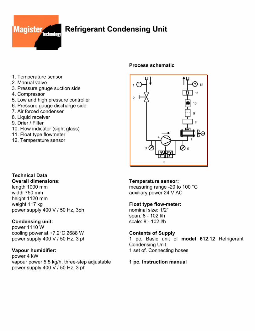
RReeffrriiggeerraanntt CCoonnddeennssiinngg UUnniitt
Technical Description mod. 612.12 The Magister Technology Refrigerant Condensing Unit model 612.12 has been specially designed to be used in conjunction with our model 612 Multi-Purpose Air Duct and Heat Transfer Unit. The unit enables supply of refrigerant R134a and water-vapour to model 612.03 Heat Transfer Element Direct Expansion Coil. All components are selected according to industrial standards and installed in a mobile plastic coated steel frame. The control cabinet facilitates refrigeranttemperature measurement at the inlet and outlet points. A float-type flow-meter enables the measurement of the refrigerant’s flow-rate. The unit can be easily connected to the individual test equipment like model 612.03 using special hoses. A three-stage humidifier produces water vapour. The humidifier can be connected to the air duct with a hose. The entire system comes with an extensive instruction manual.
Details 1. Mobile frame 2. Vapour humidifier 3. Control cabinet with measuring instruments 4. Fittings for connection with the experiment (Water vapour) 5. Fittings for connection with the experiment (Refrigerant R134a)
6. Temperature sensors 7. Manual valve 8. Float type flowmeter 9. Condenser 10. Compressor 11. Water supply hose
RReeffrriiggeerraanntt CCoonnddeennssiinngg UUnniitt
1. Temperature sensor 2. Manual valve 3. Pressure gauge suction side 4. Compressor 5. Low and high pressure controller 6. Pressure gauge discharge side 7. Air forced condenser 8. Liquid receiver 9. Drier / Filter 10. Flow indicator (sight glass) 11. Float type flowmeter 12. Temperature sensor
Process schematic
Technical Data Overall dimensions: length 1000 mm width 750 mm height 1120 mm weight 117 kg power supply 400 V / 50 Hz, 3ph Condensing unit: power 1110 W cooling power at +7.2°C 2688 W power supply 400 V / 50 Hz, 3 ph Vapour humidifier: power 4 kW vapour power 5.5 kg/h, three-step adjustable power supply 400 V / 50 Hz, 3 ph
Temperature sensor: measuring range -20 to 100 °C auxiliary power 24 V AC Float type flow-meter: nominal size: 1/2" span: 8 - 102 l/h scale: 8 - 102 l/h Contents of Supply 1 pc. Basic unit of model 612.12 Refrigerant Condensing Unit 1 set of. Connecting hoses 1 pc. Instruction manual

SSmmaallll GGaass TTuurrbbiinnee DDeemmoonnssttrraattiioonn UUnniitt mmoodd..11009922
Details 1 - Flow diagram 2 - Main switch, emergency switch 3 - Instrumentation and control section 4 - Engine section 5 - Welded frame on castors
Technical Description mod. 1092 The model 1092 Small Gas Turbine Demonstration Unit provides the mean for carrying out an extensive range of experiments in gas turbine technology. The unit consists of a single shaft gas turbine acting as a gas generator and a power turbine with dynamometer. For starting a build-in starting compressor is provided. For experiments with a gas turbine thrust jet the thrust of the single shaft gas turbine can be measured. The unit is provided with a comprehensive instrumentation to enable the students to carry out detailed experiments on a gas turbine. All instrumentation and controls are built-in on the panel which displays the flow diagram to give the student a clear indication of all components and measurements identified by symbols and indicators. For safety reasons the system is fitted with safety precautions like emergency switch and automatic power shut down in the case of extreme operating conditions like overspeed and overtemperature. The components of the unit are built and supported on a sturdy rigid stand-alone frame on castors.

SSmmaallll GGaass TTuurrbbiinnee DDeemmoonnssttrraattiioonn UUnniitt mmoodd..11009922
The engine section consists of: - Single shaft gas generator with radial compressor and turbine - Power turbine with dynamometer - Combustion chamber - Starting air compressor - Inlet air silencer and exhaust silencer - Fuel system - Oil reservoir - Oil pump - Oil cooler The instrumentation and control section consists of: - Thermocouples and digital displays for measuring the gas and air temperatures - Digital display for temperature of lubrication oil - Inductive sensor and digital display for measuring the speed of gas generator - Inductive sensor and digital display for measuring the speed of power turbine - Digital display for torque of dynamometer - Force sensor and digital display for measuring the jet thrust of the single shaft turbine - Analog display for current and voltage of dynamometer - Pressure gauge for fuel pressure - Pressure gauge for combustion chamber pressure - Pressure gauge for supply pressure of power turbine - Manometer for differential pressure of combustion chamber inlet / outlet - Orifice and manometer for air flow - Volumetric fuel gauge - Reducing valve for fuel pressure - Dynamometer load potentiometer List of Experiments - Determination of main components efficiencies - compressor - generator - power turbine - Determination of specific thrust - Determination of air mass flow - Determination of fuel flow - Determination of no-load characteristics of the turbine - compressor

SSmmaallll GGaass TTuurrbbiinnee DDeemmoonnssttrraattiioonn UUnniitt mmoodd..11009922
Technical Data Main Dimensions: L x W x H approx. 1700x750x1650 mm Weight 355 kg Supply: 230 V / 50 Hz / 1 ph Fuel: Kerosine Gas generator Speed: approx. 50000 - 90000 min-1 Thrust: 5 - 30 N Fuel consumption: max. 0.3 litre/min Dimensions: dia. 110 mm , length 270 mm Power turbine Speed approx. 10000 - 80000 min -1 Power approx. 1 kW Type: Impulse Contents of Supply 1 pc. ET 792 Small Gas Turbine Demonstration Unit 1 pc. Instruction manual