Sistemas de Comunicaciones Cap 01-06-2007 1 (1)
100
Medios Opticos
-
Upload
hans-cruz-ruiz -
Category
Documents
-
view
217 -
download
0
Transcript of Sistemas de Comunicaciones Cap 01-06-2007 1 (1)

8/13/2019 Sistemas de Comunicaciones Cap 01-06-2007 1 (1)
http://slidepdf.com/reader/full/sistemas-de-comunicaciones-cap-01-06-2007-1-1 1/100
Medios Opticos

8/13/2019 Sistemas de Comunicaciones Cap 01-06-2007 1 (1)
http://slidepdf.com/reader/full/sistemas-de-comunicaciones-cap-01-06-2007-1-1 2/100
. 2
Medios Opticos
• Explain the basics of fiber-optic cable.
• Describe how fibers can guide light for long distances.
• Describe multimode and single-mode fiber.
• Describe how fiber is installed.
• Describe the type of connectors and equipment used with fiber-optic
cable.• Explain how fiber is tested to ensure that it will function properly.
• Discuss safety issues dealing with fiber-optics.

8/13/2019 Sistemas de Comunicaciones Cap 01-06-2007 1 (1)
http://slidepdf.com/reader/full/sistemas-de-comunicaciones-cap-01-06-2007-1-1 3/100
. 3
El espectro electromagnético
• The light used in optical fiber networks is one type of electromagneticenergy.
• When an electric charge moves back and forth, or accelerates, a type
of energy called electromagnetic energy is produced.
• This energy in the form of waves can travel through a vacuum, the air,
and through some materials like glass.• An important property of any energy wave is the wavelength.
• Radio, microwaves, radar, visible light, x-rays are all types of
electromagnetic energy.

8/13/2019 Sistemas de Comunicaciones Cap 01-06-2007 1 (1)
http://slidepdf.com/reader/full/sistemas-de-comunicaciones-cap-01-06-2007-1-1 4/100
. 4
El espectro electromagnético
• The wavelength of an electromagnetic wave is determined by howfrequently the electric charge that generates the wave moves back andforth.
• If the charge moves back and forth slowly, the wavelength it generatesis a long wavelength.
• Visualize the movement of the electric charge as like that of a stick in apool of water.
• If the stick is moved back and forth slowly, it will generate ripples in thewater with a long wavelength between the tops of the ripples.
• If the stick is moved back and forth more rapidly, the ripples will have ashorter wavelength.

8/13/2019 Sistemas de Comunicaciones Cap 01-06-2007 1 (1)
http://slidepdf.com/reader/full/sistemas-de-comunicaciones-cap-01-06-2007-1-1 5/100
. 5
El espectro electromagnético

8/13/2019 Sistemas de Comunicaciones Cap 01-06-2007 1 (1)
http://slidepdf.com/reader/full/sistemas-de-comunicaciones-cap-01-06-2007-1-1 6/100
. 6
El espectro electromagnético
• Wavelengths that are not visible to the human eye are used to transmit
data over optical fiber.
• These wavelengths are slightly longer than red light and are called infrared light.
• Infrared light is used in TV remote controls.
• These wavelengths were selected because they travel through optical
fiber better than other wavelengths.

8/13/2019 Sistemas de Comunicaciones Cap 01-06-2007 1 (1)
http://slidepdf.com/reader/full/sistemas-de-comunicaciones-cap-01-06-2007-1-1 7/100. 7
Modelo de rayo de luz
• When electromagnetic waves travel out from a source, they travel in straight lines.
• These straight lines pointing out from the source are called rays.
• Think of light rays as narrow beams of light like those produced by lasers.
• In the vacuum of empty space, light travels continuously in a straight line at300,000 kilometers per second .
• However, light travels at different, slower speeds through other materials like air,water, and glass.
• When a light ray called the incident ray, crosses the boundary from one material toanother, some of the light energy in the ray will be reflected back.
• That is why you can see yourself in window glass.
• The light that is reflected back is called the reflected ray.

8/13/2019 Sistemas de Comunicaciones Cap 01-06-2007 1 (1)
http://slidepdf.com/reader/full/sistemas-de-comunicaciones-cap-01-06-2007-1-1 8/100. 8
Modelo de rayo de luz
• The light energy in the incident ray that is not reflected will enter the
glass.
• refracted ray - The entering ray will be bent at an angle from its
original path.
• How much the incident light ray is bent depends on the angle at which
the incident ray strikes the surface of the glass and the different rates
of speed at which light travels through the two substances
• The optical density of the glass determines how much the rays of light
in the glass bends.
• Optical density refers to how much a light ray slows down when it
passes through a substance.
• The greater the optical density of a material, the more it slows light
down from its speed in a vacuum.
• The ratio of the speed of light in a material to the speed of light in a
vacuum is called the Index of Refraction.

8/13/2019 Sistemas de Comunicaciones Cap 01-06-2007 1 (1)
http://slidepdf.com/reader/full/sistemas-de-comunicaciones-cap-01-06-2007-1-1 9/100. 9
Reflexión
• When a ray of light (the incident ray) strikes the shiny surface of a flatpiece of glass, some of the light energy in the ray is reflected.
• The angle between the incident ray and a line perpendicular to thesurface of the glass at the point where the incident ray strikes the glass is called the angle of incidence.
• The angle at which a light ray strikes a reflective surface determinesthe angle that the ray will reflect off the surface.
Interactive Media Activity

8/13/2019 Sistemas de Comunicaciones Cap 01-06-2007 1 (1)
http://slidepdf.com/reader/full/sistemas-de-comunicaciones-cap-01-06-2007-1-1 10/100. 10
Refración
• When a light strikes the interface between two transparentmaterials, the light divides into two parts.
• Part of the light ray is reflected back into the firstsubstance, with the angle of reflection equaling the angleof incidence.
• The remaining energy in the light ray crosses the interfaceand enters into the second substance.

8/13/2019 Sistemas de Comunicaciones Cap 01-06-2007 1 (1)
http://slidepdf.com/reader/full/sistemas-de-comunicaciones-cap-01-06-2007-1-1 11/100. 11
Refración
• If the incident ray strikes the glass surface at an exact 90-degreeangle, the ray goes straight into the glass.
• The ray is not bent. However, if the incident ray is not at an exact 90-degree angle to the surface, then the transmitted ray that enters theglass is bent.
• The bending of the entering ray is called refraction.
• How much the ray is refracted depends on the index of refraction of thetwo transparent materials.
• Interactive Media Activity

8/13/2019 Sistemas de Comunicaciones Cap 01-06-2007 1 (1)
http://slidepdf.com/reader/full/sistemas-de-comunicaciones-cap-01-06-2007-1-1 12/100. 12
Reflexión total interna
• A light ray that is being turned on and off to send data (1s and 0s) into an
optical fiber must stay inside the fiber until it reaches the far end.
• The ray must not refract into the material wrapped around the outside of the
fiber.
• The refraction would cause the loss of part of the light energy of the ray.• A design must be achieved for the fiber that will make the outside surface of
the fiber act like a mirror to the light ray moving through the fiber.
• If any light ray that tries to move out through the side of the fiber were reflected
back into the fiber at an angle that sends it towards the far end of the fiber, this
would be a good “pipe” or “wave guide” for the light waves.
R fl ió t t l

8/13/2019 Sistemas de Comunicaciones Cap 01-06-2007 1 (1)
http://slidepdf.com/reader/full/sistemas-de-comunicaciones-cap-01-06-2007-1-1 13/100. 13
Reflexión total
Interna
• The laws of reflection and refraction illustrate how to design a fiber thatguides the light waves through the fiber with a minimum energy loss.
• The following two conditions must be met for the light rays in afiber to be reflected back into the fiber without any loss due torefraction:
– The core of the optical fiber has to have a larger index of refraction(n) than the material that surrounds it. The material that surroundsthe core of the fiber is called the cladding.
– The angle of incidence of the light ray is greater than the criticalangle for the core and its cladding.

8/13/2019 Sistemas de Comunicaciones Cap 01-06-2007 1 (1)
http://slidepdf.com/reader/full/sistemas-de-comunicaciones-cap-01-06-2007-1-1 14/100

8/13/2019 Sistemas de Comunicaciones Cap 01-06-2007 1 (1)
http://slidepdf.com/reader/full/sistemas-de-comunicaciones-cap-01-06-2007-1-1 15/100. 15
Cableado de Fibra Optica
• The core is the light transmission element at the center of the optical fiber. Allthe light signals travel through the core.
• Cladding is also made of silica but with a lower index of refraction than thecore. Light rays traveling through the fiber core reflect off this core-to-claddinginterface as they move through the fiber by total internal reflection.
•Surrounding the cladding is a buffer material that is usually plastic. The buffermaterial helps shield the core and cladding from damage.
• The strength material surrounds the buffer, preventing the fiber cable frombeing stretched when installers pull it. The material used is often Kevlar , thesame material used to produce bulletproof vests.
• The outer jacket surrounds the cable to protect the fiber against abrasion,solvents, and other contaminants.

8/13/2019 Sistemas de Comunicaciones Cap 01-06-2007 1 (1)
http://slidepdf.com/reader/full/sistemas-de-comunicaciones-cap-01-06-2007-1-1 16/100. 16
Cableado de Fibra Optica
Higher bandwidth.

8/13/2019 Sistemas de Comunicaciones Cap 01-06-2007 1 (1)
http://slidepdf.com/reader/full/sistemas-de-comunicaciones-cap-01-06-2007-1-1 17/100. 17
Cableado de Fibra Optica
• If the diameter of the core of the fiber is large enough so that there are
many paths that light can take through the fiber, the fiber is called
“multimode” fiber.
• Single-mode fiber has a much smaller core that only allows light rays
to travel along one mode inside the fiber.

8/13/2019 Sistemas de Comunicaciones Cap 01-06-2007 1 (1)
http://slidepdf.com/reader/full/sistemas-de-comunicaciones-cap-01-06-2007-1-1 18/100. 18
Cableado de Fibra Optica
• Every fiber-optic cable used for networking consists of two glass fibers
encased in separate sheaths.
• One fiber carries transmitted data from device A to device B.
• The second fiber carries data from device B to device A.
• This provides a full-duplex communication link.
• Typically, these two fiber cables will be in a single outer jacket until they
reach the point at which connectors are attached.

8/13/2019 Sistemas de Comunicaciones Cap 01-06-2007 1 (1)
http://slidepdf.com/reader/full/sistemas-de-comunicaciones-cap-01-06-2007-1-1 19/100. 19
Cableado de Fibra Optica
• Warning: The laser light used with single-mode has a longerwavelength than can be seen.
• The laser is so strong that it can seriously damage eyes.• Never look at the near end of a fiber that is connected to a device at
the far end.
• Never look into the transmit port on a NIC, switch, or router.
• Remember to keep protective covers over the ends of fiber and
inserted into the fiber-optic ports of switches and routers.
Core - Cladding

8/13/2019 Sistemas de Comunicaciones Cap 01-06-2007 1 (1)
http://slidepdf.com/reader/full/sistemas-de-comunicaciones-cap-01-06-2007-1-1 20/100. 20
Dispositivos Transmisores
• The transmitter converts the electronic signals into their equivalent lightpulses.
• There are two types of light sources used to encode and transmit the
data through the cable: – A light emitting diode (LED) producing infrared light.
– Light amplification by stimulated emission radiation (LASER) a lightsource producing a thin beam of intense infrared light usually withwavelengths of 1310nm or 1550 nm.
– Lasers are used with single-mode fiber over the longer distancesinvolved in WANs or campus backbones.

8/13/2019 Sistemas de Comunicaciones Cap 01-06-2007 1 (1)
http://slidepdf.com/reader/full/sistemas-de-comunicaciones-cap-01-06-2007-1-1 21/100. 21
Dispositivos Receptores
• The receiver functions something like the photoelectric cell in a solar poweredcalculator.
• When light strikes the receiver, it produces electricity.
• The semiconductor devices that are usually used as receivers with fiber-optic
links are called p-intrinsic-n diodes (PIN photodiodes). • When struck by a pulse of light at the proper wavelength, the PIN photodiode
quickly produces an electric current of the proper voltage for the network.
• It instantly stops producing the voltage when no light strikes the PINphotodiode.
• This generates the voltage changes that represent the data 1s and 0s on a
copper cable.
8/13/2019 Sistemas de Comunicaciones Cap 01-06-2007 1 (1)
http://slidepdf.com/reader/full/sistemas-de-comunicaciones-cap-01-06-2007-1-1 22/100. 22
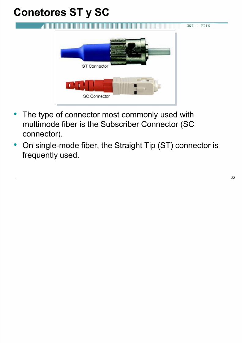
Conetores ST y SC
• The type of connector most commonly used with
multimode fiber is the Subscriber Connector (SCconnector).
• On single-mode fiber, the Straight Tip (ST) connector is
frequently used.

8/13/2019 Sistemas de Comunicaciones Cap 01-06-2007 1 (1)
http://slidepdf.com/reader/full/sistemas-de-comunicaciones-cap-01-06-2007-1-1 23/100. 23
Panel de conexiones de Fibra Optica

8/13/2019 Sistemas de Comunicaciones Cap 01-06-2007 1 (1)
http://slidepdf.com/reader/full/sistemas-de-comunicaciones-cap-01-06-2007-1-1 24/100

8/13/2019 Sistemas de Comunicaciones Cap 01-06-2007 1 (1)
http://slidepdf.com/reader/full/sistemas-de-comunicaciones-cap-01-06-2007-1-1 25/100
. 25
Señal y ruido en Fibra Optica
• Fiber-optic cable is not affected by the sources of external noise thatcause problems on copper media because external light cannot enterthe fiber except at the transmitter end.
• Although fiber is the best of all the transmission media at carrying large
amounts of data over long distances, fiber is not without problems.When light travels through fiber, some of the light energy is lost.
• The most important factor is scattering.
– The scattering of light in a fiber is caused by microscopic non-uniformity (distortions) in the fiber that reflects and scatters some ofthe light energy.

8/13/2019 Sistemas de Comunicaciones Cap 01-06-2007 1 (1)
http://slidepdf.com/reader/full/sistemas-de-comunicaciones-cap-01-06-2007-1-1 26/100
. 26
Señal y ruido en Fibra Optica
• Absorption is another cause of light energy loss. – When a light ray strikes some types of chemical impurities in a
fiber, the impurities absorb part of the energy.
– This light energy is converted to a small amount of heat energy.
– Absorption makes the light signal a little dimmer.
• Another factor that causes attenuation of the light signal ismanufacturing irregularities or roughness in the core-to-claddingboundary.
– Any microscopic imperfections in the thickness or symmetry of thefiber will cut down on total internal reflection and the cladding will
absorb some light energy.

8/13/2019 Sistemas de Comunicaciones Cap 01-06-2007 1 (1)
http://slidepdf.com/reader/full/sistemas-de-comunicaciones-cap-01-06-2007-1-1 27/100
. 27
Señal y ruido en Fibra Optica
• Dispersion of a light flash also limits transmission distances on a fiber.
– Dispersion is the technical term for the spreading of pulses of light
as they travel down the fiber

8/13/2019 Sistemas de Comunicaciones Cap 01-06-2007 1 (1)
http://slidepdf.com/reader/full/sistemas-de-comunicaciones-cap-01-06-2007-1-1 28/100
Medios Wireless

8/13/2019 Sistemas de Comunicaciones Cap 01-06-2007 1 (1)
http://slidepdf.com/reader/full/sistemas-de-comunicaciones-cap-01-06-2007-1-1 29/100
. 29
Medios Inalambricos
• Wireless LAN organizations and standards
• Wireless devices and topologies
• How wireless LANs communicate
• Authentication and association
• The radio wave and microwave spectrums• Signals and noise on a WLANs
• Wireless security

8/13/2019 Sistemas de Comunicaciones Cap 01-06-2007 1 (1)
http://slidepdf.com/reader/full/sistemas-de-comunicaciones-cap-01-06-2007-1-1 30/100
. 30
Estandares Wireless LAN
• IEEE is the prime issuer of standards for wireless networks.
• The standards have been created within the framework of the regulationscreated by the Federal Communications Commission (FCC).
• 802.11 standard is Direct Sequence Spread Spectrum (DSSS).
– DSSS applies to wireless devices operating within a 1 to 2 Mbpsrange.
• 802.11b may also be called Wi-Fi™ or high-speed wireless and refers toDSSS systems that operate at 1, 2, 5.5 and 11 Mbps.
– The majority of 802.11b devices still fail to match the 11 Mbpsthroughput and generally function in the 2 to 4 Mbps range.
• 802.11a covers WLAN devices operating in the 5 GHZ transmissionband.
– 802.11a is capable of supplying data throughput of 54 Mbps and withproprietary technology known as "rate doubling " has achieved 108Mbps.
– In production networks, a more standard rating is 20-26 Mbps.
• 802.11g provides the same throughout as 802.11a but with backwards
compatibility for 802.11b devices.

8/13/2019 Sistemas de Comunicaciones Cap 01-06-2007 1 (1)
http://slidepdf.com/reader/full/sistemas-de-comunicaciones-cap-01-06-2007-1-1 31/100
. 31
Dipositivos Wireless y Topologías

8/13/2019 Sistemas de Comunicaciones Cap 01-06-2007 1 (1)
http://slidepdf.com/reader/full/sistemas-de-comunicaciones-cap-01-06-2007-1-1 32/100
. 32
Dipositivos Wireless y Topologías
• Access point (AP) is commonly installed to act as a central hub forthe WLAN "infrastructure mode".
• The AP is hard wired to the cabled LAN to provide Internet access and
connectivity to the wired network. APs are equipped with antennae andprovide wireless connectivity over a specified area referred to as a cell.
• Depending on the structural composition of the location in which the AP is installed and the size and gain of the antennae, the size of thecell could greatly vary.
• Most commonly, the range will be from 91.44 to 152.4 meters (300 to500 feet).

8/13/2019 Sistemas de Comunicaciones Cap 01-06-2007 1 (1)
http://slidepdf.com/reader/full/sistemas-de-comunicaciones-cap-01-06-2007-1-1 33/100
. 33
Dipositivos Wireless y Topologías
• Overlap, on multiple AP networks, is critical to allow for movement of
devices within the WLAN.
• Although not addressed in the IEEE standards, a 20-30% overlap isdesirable.
• This rate of overlap will permit roaming between cells, allowing for the
disconnect and reconnect activity to occur seamlessly without service
interruption.

8/13/2019 Sistemas de Comunicaciones Cap 01-06-2007 1 (1)
http://slidepdf.com/reader/full/sistemas-de-comunicaciones-cap-01-06-2007-1-1 34/100
. 34
Dipositivos Wireless y Topologías
• When a client is activated within the WLAN, it will start "listening" for a
compatible device with which to "associate".• This is referred to as "scanning" and may be active or passive.
• Active scanning causes a probe request to be sent from the wirelessnode seeking to join the network.
• The probe request will contain the Service Set Identifier (SSID) of the
network it wishes to join.• When an AP with the same SSID is found, the AP will issue a proberesponse.
• The authentication and association steps are completed.
• From webpedia.com
– Short for Service Set Identifier, a 32-character unique identifier attached tothe header of packets sent over a WLAN that acts as a password when amobile device tries to connect to the BSS. The SSID differentiates oneWLAN from another, so all access points and all devices attempting toconnect to a specific WLAN must use the same SSID. A device will not bepermitted to join the BSS unless it can provide the unique SSID. Becausean SSID can be sniffed in plain text from a packet it does not supply any
security to the network.

8/13/2019 Sistemas de Comunicaciones Cap 01-06-2007 1 (1)
http://slidepdf.com/reader/full/sistemas-de-comunicaciones-cap-01-06-2007-1-1 35/100

8/13/2019 Sistemas de Comunicaciones Cap 01-06-2007 1 (1)
http://slidepdf.com/reader/full/sistemas-de-comunicaciones-cap-01-06-2007-1-1 36/100
. 36
Configurando el SSID en el Access Point

8/13/2019 Sistemas de Comunicaciones Cap 01-06-2007 1 (1)
http://slidepdf.com/reader/full/sistemas-de-comunicaciones-cap-01-06-2007-1-1 37/100
. 37
Como se comunican las Wireless LAN
• After establishing connectivity to the WLAN, a node will pass frames in
the same manner as on any other 802.x network.• WLANs do not use a standard 802.3 frame.
• Therefore, using the term wireless Ethernet is misleading.
• There are three types of frames: control, management, and data.
• Only the data frame type is similar to 802.3 frames.

8/13/2019 Sistemas de Comunicaciones Cap 01-06-2007 1 (1)
http://slidepdf.com/reader/full/sistemas-de-comunicaciones-cap-01-06-2007-1-1 38/100
. 38
Como se comunican las Wireless LAN
• Since radio frequency (RF) is a shared medium, collisions can occur
just as they do on wired shared medium.
• The major difference is that there is no method by which the sourcenode is able to detect that a collision occurred.
• For that reason WLANs use Carrier Sense Multiple Access/Collision
Avoidance (CSMA/CA).
• This is somewhat like Ethernet CSMA/CD.
C

8/13/2019 Sistemas de Comunicaciones Cap 01-06-2007 1 (1)
http://slidepdf.com/reader/full/sistemas-de-comunicaciones-cap-01-06-2007-1-1 39/100
. 39
Como se comunican las Wireless LAN
• When a source node sends a frame, the receiving node returns a
positive acknowledgment (ACK). • This can cause consumption of 50% of the available bandwidth.
• This overhead when combined with the collision avoidance protocol
overhead reduces the actual data throughput to a maximum of 5.0 to
5.5 Mbps on an 802.11b wireless LAN rated at 11 Mbps.
• Performance of the network will also be affected by signal strength anddegradation in signal quality due to distance or interference.
• As the signal becomes weaker, Adaptive Rate Selection (ARS) may be
invoked.
• The transmitting unit will drop the data rate from 11 Mbps to 5.5 Mbps,
from 5.5 Mbps to 2 Mbps or 2 Mbps to 1 Mbps.
A i ió A i ió

8/13/2019 Sistemas de Comunicaciones Cap 01-06-2007 1 (1)
http://slidepdf.com/reader/full/sistemas-de-comunicaciones-cap-01-06-2007-1-1 40/100
. 40
Autenticación y Asociación
• Unauthenticated and unassociated
– The node is disconnected from the network and not
associated to an access point.• Authenticated and unassociated
– The node has been authenticated on the network but
has not yet associated with the access point.
• Authenticated and associated – The node is connected to the network and able to
transmit and receive data through the access point.
Mét d d A t ti ió

8/13/2019 Sistemas de Comunicaciones Cap 01-06-2007 1 (1)
http://slidepdf.com/reader/full/sistemas-de-comunicaciones-cap-01-06-2007-1-1 41/100
. 41
Métodos de Autenticación
• IEEE 802.11 lists two types of authentication processes.
• The first authentication process is the open system. – This is an open connectivity standard in which only the SSID must
match.
– This may be used in a secure or non-secure environment althoughthe ability of low level network „sniffers‟ to discover the SSID of theWLAN is high.
• The second process is the shared key.
– This process requires the use of Wireless Equivalency Protocol(WEP) encryption.
– WEP is a fairly simple algorithm using 64 and 128 bit keys.
– The AP is configured with an encrypted key and nodes attemptingto access the network through the AP must have a matching key.
– Statically assigned WEP keys provide a higher level of securitythan the open system but are def in i tely not hack proo f .
• The problem of unauthorized entry into WLANs is being addressed bya number of new security solution technologies.
L d d di l i d

8/13/2019 Sistemas de Comunicaciones Cap 01-06-2007 1 (1)
http://slidepdf.com/reader/full/sistemas-de-comunicaciones-cap-01-06-2007-1-1 42/100
. 42
Las ondas de radio y el espectro microondas
• Computers send data signals electronically.
• Radio transmitters convert these electrical signals to radio waves.
• Changing electric currents in the antenna of a transmitter generates theradio waves.
• However, radio waves attenuate as they move out from the transmittingantenna.
• In a WLAN, a radio signal measured at a distance of just 10 meters (30feet) from the transmitting antenna would be only 1/100th of its original
strength.
M d l ió

8/13/2019 Sistemas de Comunicaciones Cap 01-06-2007 1 (1)
http://slidepdf.com/reader/full/sistemas-de-comunicaciones-cap-01-06-2007-1-1 43/100
. 43
Modulación
• The process of altering the carrier signal that will enter the antenna of thetransmitter is called modulation.
• There are three basic ways in which a radio carrier signal can be modulated.
• For example, Amplitude Modulated (AM) radio stations modulate the height(amplitude) of the carrier signal .
• Frequency Modulated (FM) radio stations modulate the frequency of thecarrier signal as determined by the electrical signal from the microphone.
• In WLANs, a third type of modulation called phase modulation is used tosuperimpose the data signal onto the carrier signal that is broadcast by the
transmitter.
S ñ l R id WLAN

8/13/2019 Sistemas de Comunicaciones Cap 01-06-2007 1 (1)
http://slidepdf.com/reader/full/sistemas-de-comunicaciones-cap-01-06-2007-1-1 44/100
. 44
Señal y Ruido en una WLAN
• When using RF technology many kinds of interference must be takeninto consideration.
• In homes and offices, a device that is often overlooked as causinginterference is the standard microwave oven.
• Leakage from a microwave of as little as one watt into the RF spectrum
can cause major network disruption.• Wireless phones operating in the 2.4GHZ spectrum can also causenetwork disorder.
• Generally the RF signal will not be affected by even the most extremeweather conditions. However, fog or very high moisture conditions canand do affect wireless networks. Lightning can also charge the
atmosphere and alter the path of a transmitted signal.

8/13/2019 Sistemas de Comunicaciones Cap 01-06-2007 1 (1)
http://slidepdf.com/reader/full/sistemas-de-comunicaciones-cap-01-06-2007-1-1 45/100
Capitulo 4 – Fundamentos deEthernet
Li it i C 1

8/13/2019 Sistemas de Comunicaciones Cap 01-06-2007 1 (1)
http://slidepdf.com/reader/full/sistemas-de-comunicaciones-cap-01-06-2007-1-1 46/100
. 46
Limitaciones Capa 1
• Layer 1 involves media, signals, bit streams that travel on media,
components that put signals on media, and various topologies.• Layer 1 cannot communicate with the upper-level layers; Layer 2 does
that with Logica l L ink Contro l (LLC) .
• Layer 1 cannot name or identify computers; Layer 2 uses an
addressing (or naming) process.
• Layer 1 can only describe streams of bits; Layer 2 uses f raming toorganize or group the bits.
• Layer 1 cannot decide which computer will transmit binary data from a
group that are all trying to transmit at the same time. Layer 2 uses a
system called Media Access Control (MAC).
S b d l d d t

8/13/2019 Sistemas de Comunicaciones Cap 01-06-2007 1 (1)
http://slidepdf.com/reader/full/sistemas-de-comunicaciones-cap-01-06-2007-1-1 47/100
. 47
LLC (Logical Link Control)
MAC (Media Access Control)
IEEE 802 Extension to the
OSI Model
Subcapas de enlace de datos
The Institute of Electrical and Electronic Engineers (IEEE) is aprofessional organization that defines network standards.
IEEE 802.3 and IEEE 802.5 are the predominant and best known LAN
standards. The IEEE divides the OSI data link layer into two separate sublayers.
Recognized IEEE sublayers are:
Media Access Control (MAC) (transitions down to media)
Logical Link Control (LLC) (transitions up to the network layer)
LLC S b C t l d E l Ló i

8/13/2019 Sistemas de Comunicaciones Cap 01-06-2007 1 (1)
http://slidepdf.com/reader/full/sistemas-de-comunicaciones-cap-01-06-2007-1-1 48/100
. 48
LLC – Subcapa Control de Enlace Lógico
Logical link sublayer allows part of the data link layer to function
independently from existing technologies.
Provides versatility in services to network layer protocols that are above
it, while communicating effectively with the variety of technologies below
it.
The LLC, as a sublayer, participates in the encapsulation process.
It adds two addressing components of the 802.2 specification - the
Destination Service Access Point (DSAP) and the Source Service
Access Point (SSAP). (Later)
LLC Subcapa Control de Enlace Lógico

8/13/2019 Sistemas de Comunicaciones Cap 01-06-2007 1 (1)
http://slidepdf.com/reader/full/sistemas-de-comunicaciones-cap-01-06-2007-1-1 49/100
. 49
LLC – Subcapa Control de Enlace Lógico
Defined in the IEEE 802.2 specification
Defines a number of fields in the data link layer frames that enable
multiple higher-layer protocols to share a single physical data link.
The LLC acts as a managing buffer between the “executive” upperlayers and the “shipping department” lower layers.
MAC Subcapa Control de Acceso al Medio

8/13/2019 Sistemas de Comunicaciones Cap 01-06-2007 1 (1)
http://slidepdf.com/reader/full/sistemas-de-comunicaciones-cap-01-06-2007-1-1 50/100
. 50
MAC – Subcapa Control de Acceso al Medio
The Media Access Control (MAC) sublayer deals with the protocols that
a host follows in order to access the physical media.
Responsible for the actual framing
builds the 1s and 0s to hand off to the physical layer. Responsible for media access: (later)
Contention
Token Passing
Polling
802 2 LLC

8/13/2019 Sistemas de Comunicaciones Cap 01-06-2007 1 (1)
http://slidepdf.com/reader/full/sistemas-de-comunicaciones-cap-01-06-2007-1-1 51/100
. 51
802.2 LLC
IPX IPAPPLE-
TALK
LLC
Layer 3
Layer 2 - LLC
MAC &Layer 1 Ethernet TokenRing
FDDI* *
**
* Legacy technologies

8/13/2019 Sistemas de Comunicaciones Cap 01-06-2007 1 (1)
http://slidepdf.com/reader/full/sistemas-de-comunicaciones-cap-01-06-2007-1-1 52/100
Ethernet vs IEEE 802 3

8/13/2019 Sistemas de Comunicaciones Cap 01-06-2007 1 (1)
http://slidepdf.com/reader/full/sistemas-de-comunicaciones-cap-01-06-2007-1-1 53/100
. 53
Ethernet vs IEEE 802.3
• Most of the time, the term “Ethernet” is used to mean IEEE
802.3
• For the most part, Ethernet and IEEE 802.3 are used
interchangeably, even though they are not really the same
thing.
• We will discuss this more later.
La dirección MAC

8/13/2019 Sistemas de Comunicaciones Cap 01-06-2007 1 (1)
http://slidepdf.com/reader/full/sistemas-de-comunicaciones-cap-01-06-2007-1-1 54/100
. 54
La dirección MAC
• MAC addresses are:
– 48 bits in length
– Expressed as 12 hexadecimal digits.
– The first 6 hexadecimal digits, which are administered by theIEEE, identify the manufacturer or vendor and thus comprise theOrganizational Unique Identif ier (OUI) .
– The remaining 6 hexadecimal digits comprise the interface serial
number , or another value administered by the specific vendor.
• MAC addresses are sometimes referred to as burned-in addresses (BIAs) because they are burned into read-only memory (ROM) and are copied intorandom-access memory (RAM) when the NIC initializes
Decimal Binary Hex

8/13/2019 Sistemas de Comunicaciones Cap 01-06-2007 1 (1)
http://slidepdf.com/reader/full/sistemas-de-comunicaciones-cap-01-06-2007-1-1 55/100
. 55
Decimal, Binary, Hex
Dec Bin Hex Dec Bin Hex
0 = 0000 = 0 8 = 1000 = 8
1 = 0001 = 1 9 = 1001 = 9
2 = 0010 = 2 10 = 1010 = A3 = 0011 = 3 11 = 1011 = B
4 = 0100 = 4 12 = 1100 = C
5 = 0101 = 5 13 = 1101 = D6 = 0110 = 6 14 = 1110 = E
7 = 0111 = 7 15 = 1111 = F
Computadoras sin nombre

8/13/2019 Sistemas de Comunicaciones Cap 01-06-2007 1 (1)
http://slidepdf.com/reader/full/sistemas-de-comunicaciones-cap-01-06-2007-1-1 56/100
. 56
Computadoras sin nombre
Formato de dirección MAC

8/13/2019 Sistemas de Comunicaciones Cap 01-06-2007 1 (1)
http://slidepdf.com/reader/full/sistemas-de-comunicaciones-cap-01-06-2007-1-1 57/100
. 57
Formato de dirección MAC
OUI unique
• An Intel MAC address: 00-20-E0-6B-17-62• 0000 0000 - 0010 0000 – 1110 0000 - 0110 1011 – 0001 0111 – 0110 0010
• IEEE OUI FAQs: http://standards.ieee.org/faqs/OUI.html
Dec Bin Hex Dec Bin Hex
0 = 0000 = 0 8 = 1000 = 8
1 = 0001 = 1 9 = 1001 = 9
2 = 0010 = 2 10 = 1010 = A3 = 0011 = 3 11 = 1011 = B
4 = 0100 = 4 12 = 1100 = C
5 = 0101 = 5 13 = 1101 = D
6 = 0110 = 6 14 = 1110 = E
7 = 0111 = 7 15 = 1111 = F
Las Direcciones MAC son planas

8/13/2019 Sistemas de Comunicaciones Cap 01-06-2007 1 (1)
http://slidepdf.com/reader/full/sistemas-de-comunicaciones-cap-01-06-2007-1-1 58/100
. 58
Las Direcciones MAC son planas
• MAC addresses provide a way for computers to identify themselves.
• They give hosts a permanent, unique name.
• The number of possible MAC addresses is 16^12 (or over 2 trillion!).
• MAC addresses do have one major disadvantage:
– They have no structure, and are considered flat address spaces.
– Like using just a name when sending a letter instead of a structured
address.
Ejemplo de encapsulamiento de datos

8/13/2019 Sistemas de Comunicaciones Cap 01-06-2007 1 (1)
http://slidepdf.com/reader/full/sistemas-de-comunicaciones-cap-01-06-2007-1-1 59/100
. 59
Application
Header + data
Ejemplo de encapsulamiento de datos
Let us focus on the Layer 2, Data Link, Ethernet Frame fornow.
010010100100100100111010010001101000…
Application Layer
Layer 4: Transport Layer
Layer 3: Network Layer
Layer 2:Data LinkLayer
Layer 1: PhysicalLayer
Comunicaciones de igual a igual

8/13/2019 Sistemas de Comunicaciones Cap 01-06-2007 1 (1)
http://slidepdf.com/reader/full/sistemas-de-comunicaciones-cap-01-06-2007-1-1 60/100
. 60
Comunicaciones de igual a igual
• Again, we are dealing with just the Data Link (and
Physical) layers.
Routers
Switches
Repeaters,Hubs, Cables,
etc.
HostsHosts
Routers
Switches
Repeaters,Hubs,
Cables, etc.
Trama de Enlace de Datos Genérica

8/13/2019 Sistemas de Comunicaciones Cap 01-06-2007 1 (1)
http://slidepdf.com/reader/full/sistemas-de-comunicaciones-cap-01-06-2007-1-1 61/100
. 61
Trama de Enlace de Datos Genérica
• A message is “framed” at layer two.
• Framing provides order, or structure, to the bitstream.
Tramas ethernet y las direcciones MAC

8/13/2019 Sistemas de Comunicaciones Cap 01-06-2007 1 (1)
http://slidepdf.com/reader/full/sistemas-de-comunicaciones-cap-01-06-2007-1-1 62/100
. 62
Tramas ethernet y las direcciones MAC
• DA = Destination MAC Address
• SA = Source MAC Address

8/13/2019 Sistemas de Comunicaciones Cap 01-06-2007 1 (1)
http://slidepdf.com/reader/full/sistemas-de-comunicaciones-cap-01-06-2007-1-1 63/100
. 63
• Let‟s bring the following together:
– Ethernet Frames and MAC Addresses
– Sending and receiving Ethernet frames on a
bus
– CSMA/CD – Sending and receiving Ethernet frames via a
hub
– Sending and receiving Ethernet frames via aswitch
– 5-4-3 rule
Sending and receiving Ethernet frames on a bus

8/13/2019 Sistemas de Comunicaciones Cap 01-06-2007 1 (1)
http://slidepdf.com/reader/full/sistemas-de-comunicaciones-cap-01-06-2007-1-1 64/100
. 64
Sending and receiving Ethernet frames on a bus
• When an Ethernet frame is sent out on the “bus” all
devices on the bus receive it.
• What do they do with it?
1111 2222 3333 nnnn Abbreviated
MAC Addresses
11113333

8/13/2019 Sistemas de Comunicaciones Cap 01-06-2007 1 (1)
http://slidepdf.com/reader/full/sistemas-de-comunicaciones-cap-01-06-2007-1-1 65/100
Sending and receiving Ethernet frames on a bus

8/13/2019 Sistemas de Comunicaciones Cap 01-06-2007 1 (1)
http://slidepdf.com/reader/full/sistemas-de-comunicaciones-cap-01-06-2007-1-1 66/100
. 66
Sending and receiving Ethernet frames on a bus
• So, what happens when multiple computers try to transmit
at the same time?
1111 2222 3333 nnnn Abbreviated
MAC Addresses
Sending and receiving Ethernet frames on a bus

8/13/2019 Sistemas de Comunicaciones Cap 01-06-2007 1 (1)
http://slidepdf.com/reader/full/sistemas-de-comunicaciones-cap-01-06-2007-1-1 67/100
. 67
Sending and receiving Ethernet frames on a bus
Collision!
1111 2222 3333 nnnn Abbreviated
MAC Addresses
X
Access Methods

8/13/2019 Sistemas de Comunicaciones Cap 01-06-2007 1 (1)
http://slidepdf.com/reader/full/sistemas-de-comunicaciones-cap-01-06-2007-1-1 68/100
. 68
Two common types of access methods for LANs include
• Non-Deterministic: Contention methods (Ethernet, IEEE 802.3)
– Only one signal can be on a network segment at
one time.
– Collisions are a normal occurrence on an
Ethernet/802.3 LAN
• Deterministic: Token Passing (Token Ring)
– more later
Access Methods
CSMA/CD (Carrier Sense Multiple Access

8/13/2019 Sistemas de Comunicaciones Cap 01-06-2007 1 (1)
http://slidepdf.com/reader/full/sistemas-de-comunicaciones-cap-01-06-2007-1-1 69/100
. 69
with Collision Detection)
CSMA/CD Common contention method used with Ethernet
and IEEE 802.3• “Let everyone have access whenever they want and we
will work it out somehow.”
CSMA/CD and Collisions

8/13/2019 Sistemas de Comunicaciones Cap 01-06-2007 1 (1)
http://slidepdf.com/reader/full/sistemas-de-comunicaciones-cap-01-06-2007-1-1 70/100
. 70
CSMA/CD (Carrier Sense Multiple Access with Collision Detection)
• Listens to the network‟s shared media to see if any other users on“on the line” by trying to sense a neutral electrical signal or carrier.
• If no transmission is sensed, then multiple access allows anyoneonto the media without any further permission required.
• If two PCs detect a neutral signal and access the shared media at the
exact same time, a col l is ion occurs and is detected .• The PCs sense the collision by being unable to deliver the entireframe (coming soon) onto the network. (This is why there areminimum frame lengths along with cable distance and speedlimitations. This includes the 5-4-3 rule.)
• When a collision occurs, a jamming signal is sent out by the first PC
to detect the collision.• Using either a priority or random backoff scheme, the PCs wait
certain amount of time before retransmitting.
• If collisions continue to occur, the PCs random interval is doubled,lessening the chances of a collision.
CSMA/CD and Collisions
CSMA/CD and Collisions

8/13/2019 Sistemas de Comunicaciones Cap 01-06-2007 1 (1)
http://slidepdf.com/reader/full/sistemas-de-comunicaciones-cap-01-06-2007-1-1 71/100
. 71
And as we said,
• When information (frame) is transmitted, every PC/NIC on theshared media copies part of the transmitted frame to see if thedestination address matches the address of the NIC.
• If there is a match, the rest of the frame is copied
• If there is NOT a match the rest of the frame is ignored.
1111 2222 3333 nnnn AbbreviatedMAC
Addresses
11113333
Nope NopeHey, that’sme!
Notice thelocation ofthe DA!
CSMA/CD and Collisions
Sending and receiving Ethernet frames via a
h b

8/13/2019 Sistemas de Comunicaciones Cap 01-06-2007 1 (1)
http://slidepdf.com/reader/full/sistemas-de-comunicaciones-cap-01-06-2007-1-1 72/100
. 72
hub
• So, what does a hub do
when it receives
information?• Remember, a hub is
nothing more than a
multiport repeater.
1111 2222
3333 4444
5555
?
11113333
Sending and receiving Ethernet frames via a hub

8/13/2019 Sistemas de Comunicaciones Cap 01-06-2007 1 (1)
http://slidepdf.com/reader/full/sistemas-de-comunicaciones-cap-01-06-2007-1-1 73/100
. 73
Sending and receiving Ethernet frames via a hub
Hub or
Sending and receiving Ethernet frames via a
h b

8/13/2019 Sistemas de Comunicaciones Cap 01-06-2007 1 (1)
http://slidepdf.com/reader/full/sistemas-de-comunicaciones-cap-01-06-2007-1-1 74/100
. 74
hub
• The hub will flood it out allports except for the incomingport.
• Hub is a layer 1 device.• A hub does NOT look at layer
2 addresses, so it is fast intransmitting data.
• Disadvantage with hubs: Ahub or series of hubs is a
single collision domain.
• A collision will occur if any twoor more devices transmit atthe same time within thecollision domain.
1111 2222
3333 4444
5555
11113333
Nope
Nope
Nope
For me!
Sending and receiving Ethernet frames via a hub

8/13/2019 Sistemas de Comunicaciones Cap 01-06-2007 1 (1)
http://slidepdf.com/reader/full/sistemas-de-comunicaciones-cap-01-06-2007-1-1 75/100
. 75
Sending and receiving Ethernet frames via a hub
• Another disadvantage withhubs is that is take upunnecessary bandwidth on
other links.
1111 2222
3333 4444
5555
11112222
Nope Nope
Nope
For me!
Wasted
bandwidth
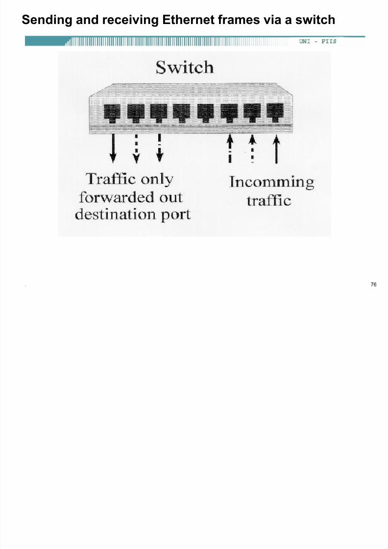
Sending and receiving Ethernet frames via a switch
8/13/2019 Sistemas de Comunicaciones Cap 01-06-2007 1 (1)
http://slidepdf.com/reader/full/sistemas-de-comunicaciones-cap-01-06-2007-1-1 76/100
. 76
g g
Sending and receiving Ethernet frames via a switch

8/13/2019 Sistemas de Comunicaciones Cap 01-06-2007 1 (1)
http://slidepdf.com/reader/full/sistemas-de-comunicaciones-cap-01-06-2007-1-1 77/100
. 77
g g
Source Address Table
Port Source MAC Add. Port Source MAC Add.
• Switches are also known aslearning bridges or learningswitches.
• A switch has a source address
table in cache (RAM) where itstores source MAC addressafter it learns about them.
• A switch receives an Ethernetframe it searches the sourceaddress table for theDestination MAC address.
• If it finds a match, it filters theframe by only sending it outthat port.
• If there is not a match if floods
it out all ports.
switch
1111
2222
3333
4444
AbbreviatedMACaddresses
11113333

8/13/2019 Sistemas de Comunicaciones Cap 01-06-2007 1 (1)
http://slidepdf.com/reader/full/sistemas-de-comunicaciones-cap-01-06-2007-1-1 78/100
Destination Address in table, Filter

8/13/2019 Sistemas de Comunicaciones Cap 01-06-2007 1 (1)
http://slidepdf.com/reader/full/sistemas-de-comunicaciones-cap-01-06-2007-1-1 79/100
. 79
,
Source Address Table
Port Source MAC Add. Port Source MAC Add.
1 1111 6 3333
• Most communications involvesome sort of client-serverrelationship or exchange ofinformation. (You will
understand this more as youlearn about TCP/IP.)
• Now 3333 sends data back to1111.
• The switch sees if it has the SAstored.
• It does NOT so it adds it. (Thiswill help next time 1111 sendsto 3333.)
• Next, it checks the DA and inour case it can filter the frame,
by sending it only out port 1.
switch
1111
2222
3333
4444
AbbreviatedMACaddresses
33331111
Destination Address in table, Filter

8/13/2019 Sistemas de Comunicaciones Cap 01-06-2007 1 (1)
http://slidepdf.com/reader/full/sistemas-de-comunicaciones-cap-01-06-2007-1-1 80/100
. 80
,
Source Address Table
Port Source MAC Add. Port Source MAC Add.
1 1111 6 3333
• Now, because both MACaddresses are in the switch‟s table,any information exchangedbetween 1111 and 3333 can besent (filtered) out the appropriateport.
• What happens when two devicessend to same destination?
• What if this was a hub?
• Where is (are) the collisiondomain(s) in this example?
switch
1111
2222
3333
4444
AbbreviatedMACaddresses
11113333
33331111
No Collisions in Switch, Buffering

8/13/2019 Sistemas de Comunicaciones Cap 01-06-2007 1 (1)
http://slidepdf.com/reader/full/sistemas-de-comunicaciones-cap-01-06-2007-1-1 81/100
. 81
, g
Source Address Table
Port Source MAC Add. Port Source MAC Add.
1 1111 6 33339 4444
• Unlike a hub, a collision doesNOT occur, which would cause
the two PCs to have to
retransmit the frames.
• Instead the switch buffers the
frames and sends them out port#6 one at a time.
• The sending PCs have no idea
that their was another PC
wanting to send to the same
destination.
switch
1111
2222
3333
4444
AbbreviatedMACaddresses
11113333
44443333
Collision Domains

8/13/2019 Sistemas de Comunicaciones Cap 01-06-2007 1 (1)
http://slidepdf.com/reader/full/sistemas-de-comunicaciones-cap-01-06-2007-1-1 82/100
. 82
Source Address Table
Port Source MAC Add. Port Source MAC Add.
1 1111 6 33339 4444
• When there is only one deviceon a switch port, the collision
domain is only between the PC
and the switch. (Cisco
curriculum is inaccurate on this
point.)• With a full-duplex PC and
switch port, there will be no
collision, since the devices and
the medium can send and
receive at the same time.
switch
1111
2222
3333
4444
AbbreviatedMACaddresses
11113333
44443333
Collision Domains
Other Information

8/13/2019 Sistemas de Comunicaciones Cap 01-06-2007 1 (1)
http://slidepdf.com/reader/full/sistemas-de-comunicaciones-cap-01-06-2007-1-1 83/100
. 83
Source Address Table
Port Source MAC Add. Port Source MAC Add.
1 1111 6 33339 4444 • How long are addresses kept in the
Source Address Table?
– 5 minutes is common on most
vendor switches.
• How do computers know the
Destination MAC address?
• ARP Caches and ARP
Requests (later)
• How many addresses can be kept
in the table?
– Depends on the size of thecache, but 1,024 addresses is
common.
• What about Layer 2 broadcasts?
– Layer 2 broadcasts (DA = all
1‟s) is flooded out all ports.
switch
1111
2222
3333
4444
AbbreviatedMACaddresses
Side Note - Transparent Bridging

8/13/2019 Sistemas de Comunicaciones Cap 01-06-2007 1 (1)
http://slidepdf.com/reader/full/sistemas-de-comunicaciones-cap-01-06-2007-1-1 84/100
. 84
p g g
• Transparent bridging (normal switching process) is defined in IEEE
802.1d describing the five bridging processes of:
– learning
– flooding filtering
– forwarding
– aging
• These will be discussed further in STP (Spanning Tree Protocol)
Transparent Bridge Process - Jeff Doyle

8/13/2019 Sistemas de Comunicaciones Cap 01-06-2007 1 (1)
http://slidepdf.com/reader/full/sistemas-de-comunicaciones-cap-01-06-2007-1-1 85/100
. 85
p g y
Receive Packet
Learn source address or refresh aging timer
Is the destination a broadcast, multicast or unknown unicast?
Are the source and destination on the same interface?
Forward unicast to correct port
Flood Packet
Filter Packet
Yes
Yes
No
No

8/13/2019 Sistemas de Comunicaciones Cap 01-06-2007 1 (1)
http://slidepdf.com/reader/full/sistemas-de-comunicaciones-cap-01-06-2007-1-1 86/100
5-4-3 Rule – Webopedia.com

8/13/2019 Sistemas de Comunicaciones Cap 01-06-2007 1 (1)
http://slidepdf.com/reader/full/sistemas-de-comunicaciones-cap-01-06-2007-1-1 87/100
. 87
• Ethernet and IEEE 802.3 implement a rule, known as the 5-4-3 rule, for thenumber of repeaters and segments on shared access Ethernet backbones in a
tree topology. The 5-4-3 rule divides the network into two types of physicalsegments: populated (user) segments, and unpopulated (link) segments. Usersegments have users' systems connected to them. Link segments are used toconnect the network's repeaters together. The rule mandates that between anytwo nodes on the network, there can only be a maximum of five segments,connected through four repeaters, or concentrators, and only three of the five
segments may contain user connections.• The Ethernet protocol requires that a signal sent out over the LAN reach everypart of the network within a specified length of time. The 5-4-3 rule ensuresthis. Each repeater that a signal goes through adds a small amount of time tothe process, so the rule is designed to minimize transmission times of thesignals.
• The 5-4-3 rule -- which was created when Ethernet, 10Base5, and 10Base2were the only types of Ethernet network available -- only applies to shared-access Ethernet backbones. A switched Ethernet network should be exemptfrom the 5-4-3 rule because each switch has a buffer to temporarily store dataand all nodes can access a switched Ethernet LAN simultaneously.

8/13/2019 Sistemas de Comunicaciones Cap 01-06-2007 1 (1)
http://slidepdf.com/reader/full/sistemas-de-comunicaciones-cap-01-06-2007-1-1 88/100
. 88
Now, back to our regular scheduled
curriculum.
Generic Data Link Frame Format

8/13/2019 Sistemas de Comunicaciones Cap 01-06-2007 1 (1)
http://slidepdf.com/reader/full/sistemas-de-comunicaciones-cap-01-06-2007-1-1 89/100
. 89
Preamble or Start Field
• When computers are connected to a physical medium, there must be away they can grab the attention of other computers to broadcast themessage, "Here comes a frame!"
• Various technologies have different ways of doing this process, but allframes, regardless of technology, have a beginning signaling sequenceof bytes.
• Depending up frame format: Preamble = 7 bytes, Start or Start ofFrame Delimiter (SFD) = 1 byte
Generic Data Link Frame Format

8/13/2019 Sistemas de Comunicaciones Cap 01-06-2007 1 (1)
http://slidepdf.com/reader/full/sistemas-de-comunicaciones-cap-01-06-2007-1-1 90/100
. 90
Address Field
• We saw how IEEE 802.3 uses Destination and Source Addresses.
• By the way: Any idea how a serial data link frame is addressed?
– Unicast address – Single device – Broadcast address – All devices
– Multicast address – Specific group of devices
Generic Data Link Frame Format

8/13/2019 Sistemas de Comunicaciones Cap 01-06-2007 1 (1)
http://slidepdf.com/reader/full/sistemas-de-comunicaciones-cap-01-06-2007-1-1 91/100
. 91
Type Field
• Usually information indicating the layer 3 protocols in the data field, I.e.
IP Packet.
• Type field values of particular note for IEEE 802.3 frames include: – 0x0600 XNS (Xerox)
– 0x0800 IP (the Internet protocol)
– 0x8137 Novell NetWare packet formatted for Ethernet II
– 0x6003 DECNET
“Ethernet” Frame Formats

8/13/2019 Sistemas de Comunicaciones Cap 01-06-2007 1 (1)
http://slidepdf.com/reader/full/sistemas-de-comunicaciones-cap-01-06-2007-1-1 92/100
. 92802.2802.3
802.3
Length Field
• In some frame formats such as 802.3, there is a length field which specifies theexact length of a frame.

8/13/2019 Sistemas de Comunicaciones Cap 01-06-2007 1 (1)
http://slidepdf.com/reader/full/sistemas-de-comunicaciones-cap-01-06-2007-1-1 93/100
. 93
• IEEE 802.3 specification limits the data portion to a maximum of 1500 bytes.
• Designed to hold a Layer 3 IP packet.• When IEEE created 802.2, it saw the need for a protocol TYPE field that
identified what was inside the “data” field.
• IEEE called its 1 byte type field DSAP (Destination Service Access Point).
• Turned out that 1 byte was not long enough to handle all the different numberof protocols.

8/13/2019 Sistemas de Comunicaciones Cap 01-06-2007 1 (1)
http://slidepdf.com/reader/full/sistemas-de-comunicaciones-cap-01-06-2007-1-1 94/100
. 94
• To accommodate more protocols IEEE added the SNAP (Subnetwork Access
Protocol) header.

8/13/2019 Sistemas de Comunicaciones Cap 01-06-2007 1 (1)
http://slidepdf.com/reader/full/sistemas-de-comunicaciones-cap-01-06-2007-1-1 95/100
. 95
• The fields of various Ethernet framing that are used for identifying the type of
data contained in a frame: – Ethernet II or DIX (DEC, Intel, Xerox) – Most common
– IEEE Ethernet (802.3)
– IEEE 802.3 with SNAP header
Generic Data Link Frame Format

8/13/2019 Sistemas de Comunicaciones Cap 01-06-2007 1 (1)
http://slidepdf.com/reader/full/sistemas-de-comunicaciones-cap-01-06-2007-1-1 96/100
. 96
Data Field
• Included along with this data, you must also send a few other bytes.
• They are called padding bytes, and are sometimes added so that the
frames have a minimum length for timing purposes.
• LLC bytes are also included with the data field in the IEEE standard
frames. (later)
Data Encapsulation Example

8/13/2019 Sistemas de Comunicaciones Cap 01-06-2007 1 (1)
http://slidepdf.com/reader/full/sistemas-de-comunicaciones-cap-01-06-2007-1-1 97/100
. 97
Application
Header + data
010010100100100100111010010001101000…
Application Layer
Layer 4: Transport Layer
Layer 3: Network Layer
Layer 2:NetworkLayer
Layer 1: PhysicalLayer
Generic Data Link Frame Format

8/13/2019 Sistemas de Comunicaciones Cap 01-06-2007 1 (1)
http://slidepdf.com/reader/full/sistemas-de-comunicaciones-cap-01-06-2007-1-1 98/100
. 98
FCS
• Used to insure that the data has arrived without corruption.
• More efficient than sending the data twice and comparing the results.
• Necessary to prevent errors.
Three Kinds of FCS

8/13/2019 Sistemas de Comunicaciones Cap 01-06-2007 1 (1)
http://slidepdf.com/reader/full/sistemas-de-comunicaciones-cap-01-06-2007-1-1 99/100
. 99
• Cyclic redundancy check (CRC)
– performs polynomial calculations on the data
• Two-dimensional parity
– adds an 8th bit that makes an 8-bit sequence have an odd or even
number of binary 1s
• Internet checksum
– adds the numbers to determine a number
Generic Data Link Frame Format

8/13/2019 Sistemas de Comunicaciones Cap 01-06-2007 1 (1)
http://slidepdf.com/reader/full/sistemas-de-comunicaciones-cap-01-06-2007-1-1 100/100
Stop Field (Other data link frame formats)
• The computer that transmits data must get the attention of other
devices, in order to start a frame, and then claim it again, to end the
frame.
• The length field implies the end, and the frame is considered endedafter the FCS.
• Sometimes there is a formal byte sequence referred to as an end-
f d li it