Sistema embebido de control para la síntesis de CACO3 a partir de ...
105
Instituto Tecnológico y de Estudios Superiores de Occidente 2016-11 Sistema embebido de control para la síntesis de CACO3 a partir de CO2 residual TéllezGirón-Enríquez, Manuel TéllezGirón-Enríquez, M. (2016). Sistema embebido de control para la síntesis de CaCO3 a partir de CO2 residual. Trabajo de obtención de grado, Especialidad en Sistemas Embebidos. Tlaquepaque, Jalisco: ITESO. Enlace directo al documento: http://hdl.handle.net/11117/4023 Este documento obtenido del Repositorio Institucional del Instituto Tecnológico y de Estudios Superiores de Occidente se pone a disposición general bajo los términos y condiciones de la siguiente licencia: http://quijote.biblio.iteso.mx/licencias/CC-BY-NC-ND-2.5-MX.pdf (El documento empieza en la siguiente página) Repositorio Institucional del ITESO rei.iteso.mx Departamento de Electrónica, Sistemas e Informática DESI - Trabajos de fin de Especialidad en Sistemas Embebidos
Transcript of Sistema embebido de control para la síntesis de CACO3 a partir de ...
Instituto Tecnológico y de Estudios Superiores de Occidente
2016-11
Sistema embebido de control para la síntesis
de CACO3 a partir de CO2 residual
TéllezGirón-Enríquez, Manuel TéllezGirón-Enríquez, M. (2016). Sistema embebido de control para la síntesis de CaCO3 a partir de
CO2 residual. Trabajo de obtención de grado, Especialidad en Sistemas Embebidos. Tlaquepaque,
Jalisco: ITESO.
Enlace directo al documento: http://hdl.handle.net/11117/4023
Este documento obtenido del Repositorio Institucional del Instituto Tecnológico y de Estudios Superiores de
Occidente se pone a disposición general bajo los términos y condiciones de la siguiente licencia:
http://quijote.biblio.iteso.mx/licencias/CC-BY-NC-ND-2.5-MX.pdf
(El documento empieza en la siguiente página)
Repositorio Institucional del ITESO rei.iteso.mx
Departamento de Electrónica, Sistemas e Informática DESI - Trabajos de fin de Especialidad en Sistemas Embebidos

INSTITUTO TECNOLÓGICO Y DE ESTUDIOS
SUPERIORES DE OCCIDENTE
Reconocimiento de validez oficial de estudios de nivel superior según acuerdo secretarial 15018, publicado en el Diario Oficial de la Federación el 29 de noviembre de 1976.
Departamento de Electrónica, Sistemas e Informática
ESPECIALIDAD EN SISTEMAS EMBEBIDOS
SISTEMA EMBEBIDO DE CONTROL PARA LA SÍNTESIS DE
CACO3 A PARTIR DE CO2 RESIDUAL
Trabajo final que para obtener el diploma de
ESPECIALISTA EN SISTEMAS EMBEBIDOS
Presenta: Manuel Téllez Girón Enríquez
Asesor: Raúl Campos Rodríguez
Asesor: Adrián Navarro Díaz
Tlaquepaque, Jalisco, Noviembre de 2016.
2
INSTITUTO TECNOLÓGICO Y DE ESTUDIOS
SUPERIORES DE OCCIDENTE
Reconocimiento de validez oficial de estudios de nivel superior según acuerdo secretarial 15018, publicado en el Diario Oficial de la Federación el 29 de noviembre de 1976.
Departamento de Electrónica, Sistemas e Informática
ESPECIALIDAD EN SISTEMAS EMBEBIDOS
SISTEMA EMBEBIDO DE CONTROL PARA LA SÍNTESIS DE
CACO3 A PARTIR DE CO2 RESIDUAL
Trabajo final que para obtener el diploma de
ESPECIALISTA EN SISTEMAS EMBEBIDOS
Presenta: Manuel Téllez Girón Enríquez
Becario CONACYT No. 591594
Asesor: Raúl Campos Rodríguez
Asesor: Adrián Navarro Díaz
Tlaquepaque, Jalisco, Noviembre de 2016.
3
INSTITUTO TECNOLÓGICO Y DE ESTUDIOS
SUPERIORES DE OCCIDENTE
Reconocimiento de validez oficial de estudios de nivel superior según acuerdo secretarial 15018, publicado en el Diario Oficial de la Federación el 29 de noviembre de 1976.
Departamento de Electrónica, Sistemas e Informática
ESPECIALIDAD EN SISTEMAS EMBEBIDOS
CACO3 SYNTHESIS FROM RESIDUAL EXHAUST CO2
EMBEDDED CONTROL SYSTEM
Final report to earn the diploma of
EMBEDDED SYSTEM SPECIALIST
Presented by: Manuel Téllez Girón Enríquez
CONACYT Scholarship No. 591594
Advisor: Raúl Campos Rodríguez
Advisor: Adrián Navarro Diaz
Tlaquepaque, Jalisco. November 16th, 2016.
4
Thanks to
Author sincerely wants to thank to:
My dear Lord for providing me life, health, resources and energy to complete this program.
My beloved wife and kids, for supporting and encouraging me whenever I have needed time
support and comprehension to let me complete this challenging endeavor.
My Parents and Sister for being always encouraging me to keep professionally and personally
growing
Consejo Nacional de Ciencia y Tecnología (CONACYT) for granting me the opportunity of the
scholarship tuition support. CONACYT Scholarship No. 591594
To ITESO for providing facilities, labs, and counseling through the board of academic members
Last, but not least to my Thesis counselors Dr. Adrián Navarro Diaz and Dr. Raúl Campos
Rodriguez for supporting and providing professional coaching and helping me to get this
milestone reached.

5
DEDICATION
Author wants to grant a sincere dedication of this work to my Family: Beba, Dan, Ana Laura and Alex for
the love they always manifested to support me with this endeavor, even when it meant my to lessen my
time shared to them, less vacation periods, and shorter weekends. God bless you all and gives all his Love
forever to you.
6
RESUMEN
En este documento es el resultado de una conceptualización de una solución tecnológica cuyo objetivo es
el de reducir y sintetizar emisiones de CO2 provenientes de vehículos automotores de combustible fósil.
El concepto presentado en este documento es el de generar un subproducto desechable y reciclable sin
riesgo ambiental o de salud (tal como el CaCO3), cuyo origen sean las emisiones contaminantes de CO2
de un vehículo automotor.
Se presenta inicialmente en la Introducción algunas soluciones empleadas actualmente para reducir
emisiones de CO2 en ambientes industriales, tales como el burbujeo del gas en agua marina para forzar a
una reacción con sales minerales del líquido; se presenta de igual manera una segunda solución que
consiste en hacer pasar el gas a través de redes de arrecifes de coral o erizos de mar con objeto de forzar
la combinación en ambientes calcáreos; y finalmente se presenta el concepto de convertidor catalítico
empleando un dispositivo colocado en el sistema de emisión de vehículos por donde se hace circular los
gases residuales con objeto de reducir las emisiones en lo posible.
Cabe comentar que los dos primeros métodos descritos, si bien se emplean actualmente en algunas
industrias que tienen cercanía geográfica con mares, requieren una alta inversión e infraestructura para
hacerlos funcionalmente viables, y en el caso del convertidor catalítico, como se expondrá posteriormente,
ha sido diseñado como sistema pasivo de reacción química que ha resultado efectivo para reducir de
manera importante emisiones de NOx y CO, pero queda fuera generalmente la reducción de emisiones de
CO2, que lamentablemente es el gas que es responsable del efecto invernadero, reducción de capa de
ozono y reduce la pureza del aire atmosférico dificultando que se desarrollen las condiciones normales de
vida en el planeta tierra.
En los trabajos previos se le da especial enfoque al análisis del convertidor catalítico y se analizan algunas
ventajas y desventajas de mantenibilidad, costo y disposición final; asimismo se mencionan algunos otros
sistemas auxiliares de reducción de contaminantes pero de manera proactiva, es decir, antes de que se
origine la combustión en el motor del vehículo, tales como: Recirculación de vapores de combustible
(EGR), control de emisiones por optimización en la relación mezcla-tiempo de chispa- control del ángulo
de encendido, todo esto a cargo de la computadora de control de combustión (ECU).
En el “estado del arte” se hace una presentación de 3 trabajos previos: El primero de ellos referente a
tecnologías de control de emisiones previamente mencionadas y adicionalmente la propuesta de uso de
combustibles alternativos de muy baja producción de contaminantes, y donde los subproductos principales
son H2O y algo de CO2. En el segundo trabajo se propone la reducción de dimensiones de motores,
considerando el sacrificio de potencia y torque pero simultáneamente empleando un diseño optimizado
del motor con objeto de no sobre-reducir el rendimiento del mismo. El tercer sistema propone, finalmente,
la síntesis de CO2 en metanol mediante métodos electroquímicos, sin embargo como el mismo texto
propone, el sistema es de muy alto costo y de difícil implementación como dispositivo en un vehículo
automotor.
7
El objetivo y la hipótesis de este documento versan sobre una solución de costo moderado, de sencillo
mantenimiento y de demanda de pocos recursos del vehículo para sintetizar CaCO3 a partir de una
reacción química del CO2, H2O condensada del aire ambiental y un elemento reactivo base de CaO2. El
subproducto CaCO3 es reciclable o desechable.
En la sección de Diseño de arquitectura, se ha propuesto el empleo de un sistema de Desarrollo de
Microchip Inc., basado en el MCU PIC18F46K22 (DM164134), de 8 bits dado que contiene la arquitectura
deseable para un sistema de la naturaleza de la solución prevista.
En el subsistema de Hardware se definen los componentes principales que corresponden a una plataforma
embebida con un número definido de I/Os digitales y la posibilidad de interconectar a un sensor de
temperatura y humedad relativa de 4 hilos, asimismo una etapa de salida de potencia para poder accionar
un arreglo de celdas Peltier para producir condensación de humedad por algoritmo de error con el punto
de rocío, una cámara de reacción donde se encontrará la muestra del material reactivo ( CaO2) y se
combinará con H2O y CO2.
El subsistema de software propone el diseño basado en capas (modelo OSI), donde en la capa de HAL de
desarrollan drivers para el bus SPI de 4 hilos para el sensor de temperatura (SHT11), un segundo bus SPI
para el control de la pantalla OLED integrada. En la capa de aplicación se propone módulo de manejo de
gráficos en la pantalla OLED, módulo de manejo del sensor de temperatura con funciones de cálculo de
traducción de protocolo, cálculo de punto de rocío y control discreto de actuadores de arreglo Peltier y un
posible actuador de ingreso/purga de humedad. Asimismo en las funciones de la aplicación se incorporan
algoritmos para linearizar las lecturas del sensor, de-saturación de membrana del sensor SHT11 y control
de indicadores discretos.
Derivado de un análisis de eficiencia, portabilidad, costo de implementación y robustez del código, se
elige como plataforma de Desarrollo el IDE MPLAB V8.90, el compilador CCS V4.75 que tiene como
ventaja la implementación rápida de un RTOS nativo, configurable a pre-emptive o colaborativo, y las
herramientas ICD3 y PICkit3 que permiten programación y depuración en tiempo real y en circuito.
Finalmente si bien no se alcanzó a construir o validar un prototipo físico del concepto, las pruebas
funcionales a nivel concepto arrojan que el sistema es factible de llevar a implementación y conclusión
como un dispositivo, ya sea de implementación de fábrica en el vehículo, o alternativamente como un
dispositivo post-venta (aftermarket) para ser adaptado a cualquier vehículo automotor.
8
ABSTRACT
This work obeys to the crescent need on thinking “out of the box” with innovative solutions to the
environmental challenges the world is facing from some years to date. This document tries to address
an effective implementation of an embedded control system, as part of a major system, to recycle
residual Carbon dioxide (CaCo2) exhaust emissions from a gas fueled vehicle in order to synthesize,
with the aid of low cost and easily acquirable and non-hazardous chemicals such as Calcium Oxide
(CaO) , into a bio-degradable aside non health hazard sub-product like Calcium Carbonate ( CaCo3)
which can be re-used otherwise safely and environmentally friendly disposed.
First part of this Thesis states the objectives and theoretical framework as well as state of the art of
existing solutions. Second part will get into details of the embedded system implementation scoping
the hardware proposal, as well as the technical Embedded Software Engineering, design, validation
and code implementation phases, and finally a third part will focus on the future work which will be
aimed to lead to an interest of continuing the work in future system level implementations, including
chemical reservoir design, environmental humidity acquisition chamber and a means of disposing of
the non-toxic final product that should be freely either recycled or disposed easily without
representing a bio or health hazard.
9
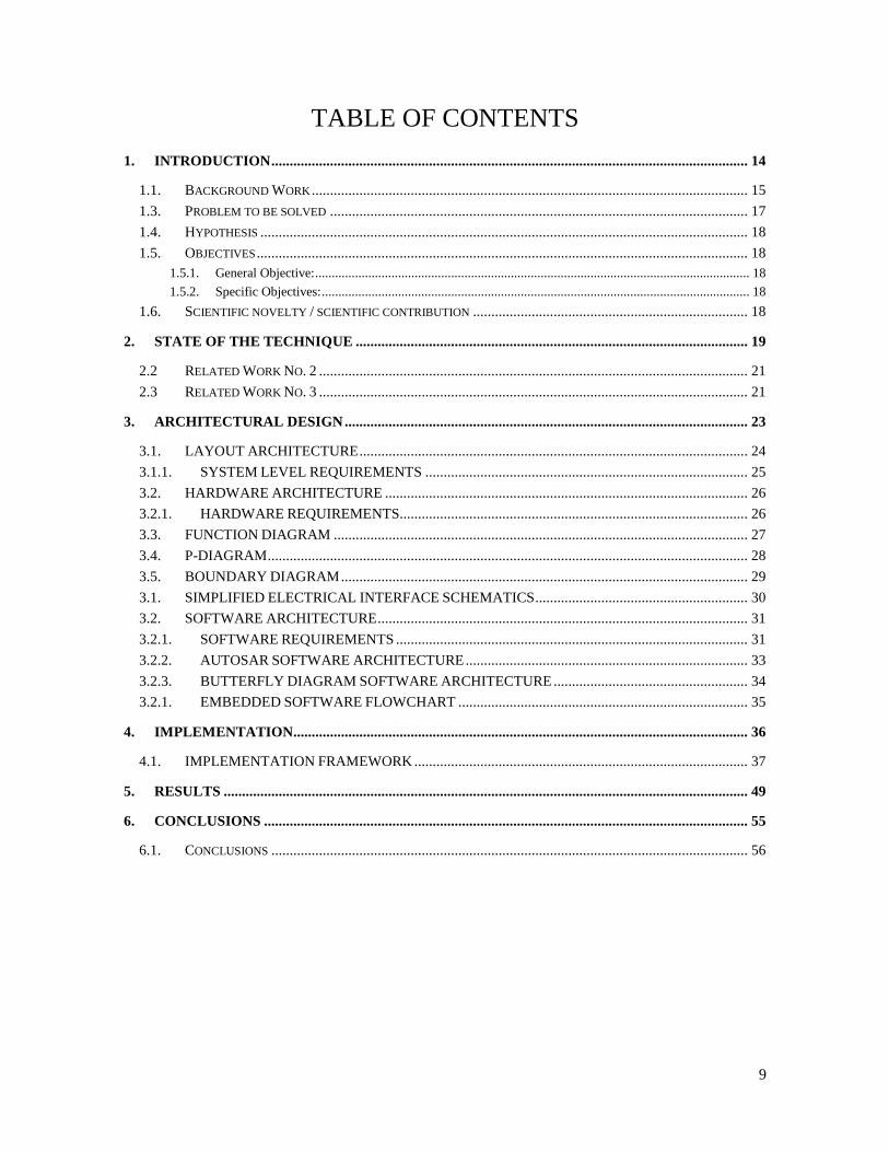
TABLE OF CONTENTS
1. INTRODUCTION .................................................................................................................................. 14
1.1. BACKGROUND WORK ....................................................................................................................... 15
1.3. PROBLEM TO BE SOLVED .................................................................................................................. 17
1.4. HYPOTHESIS ..................................................................................................................................... 18
1.5. OBJECTIVES ...................................................................................................................................... 18 1.5.1. General Objective: ................................................................................................................................... 18 1.5.2. Specific Objectives: ................................................................................................................................. 18
1.6. SCIENTIFIC NOVELTY / SCIENTIFIC CONTRIBUTION ........................................................................... 18
2. STATE OF THE TECHNIQUE ........................................................................................................... 19
2.2 RELATED WORK NO. 2 ..................................................................................................................... 21
2.3 RELATED WORK NO. 3 ..................................................................................................................... 21
3. ARCHITECTURAL DESIGN .............................................................................................................. 23
3.1. LAYOUT ARCHITECTURE .......................................................................................................... 24
3.1.1. SYSTEM LEVEL REQUIREMENTS ........................................................................................ 25
3.2. HARDWARE ARCHITECTURE ................................................................................................... 26
3.2.1. HARDWARE REQUIREMENTS ............................................................................................... 26
3.3. FUNCTION DIAGRAM ................................................................................................................. 27
3.4. P-DIAGRAM ................................................................................................................................... 28
3.5. BOUNDARY DIAGRAM ............................................................................................................... 29
3.1. SIMPLIFIED ELECTRICAL INTERFACE SCHEMATICS .......................................................... 30
3.2. SOFTWARE ARCHITECTURE ..................................................................................................... 31
3.2.1. SOFTWARE REQUIREMENTS ................................................................................................ 31
3.2.2. AUTOSAR SOFTWARE ARCHITECTURE ............................................................................. 33
3.2.3. BUTTERFLY DIAGRAM SOFTWARE ARCHITECTURE ..................................................... 34
3.2.1. EMBEDDED SOFTWARE FLOWCHART ............................................................................... 35
4. IMPLEMENTATION............................................................................................................................ 36
4.1. IMPLEMENTATION FRAMEWORK ........................................................................................... 37
5. RESULTS ............................................................................................................................................... 49
6. CONCLUSIONS .................................................................................................................................... 55
6.1. CONCLUSIONS .................................................................................................................................. 56
10
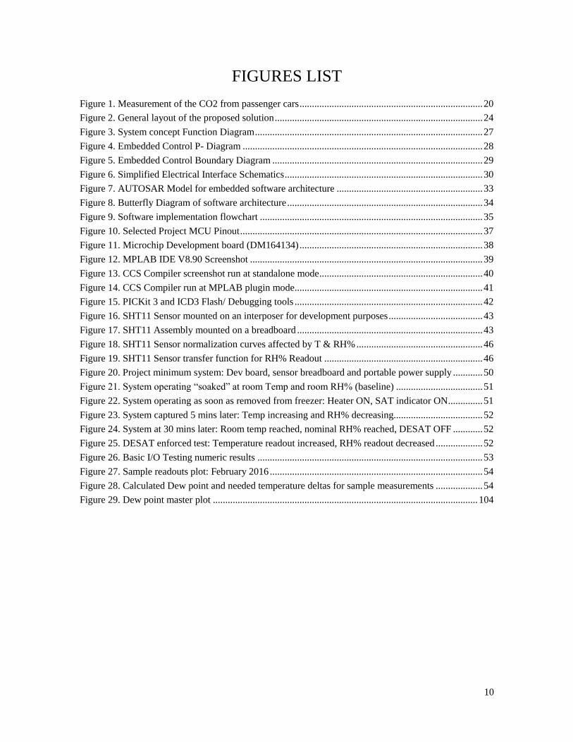
FIGURES LIST
Figure 1. Measurement of the CO2 from passenger cars .......................................................................... 20
Figure 2. General layout of the proposed solution .................................................................................... 24
Figure 3. System concept Function Diagram ............................................................................................ 27
Figure 4. Embedded Control P- Diagram ................................................................................................. 28
Figure 5. Embedded Control Boundary Diagram ..................................................................................... 29
Figure 6. Simplified Electrical Interface Schematics ................................................................................ 30
Figure 7. AUTOSAR Model for embedded software architecture ........................................................... 33
Figure 8. Butterfly Diagram of software architecture ............................................................................... 34
Figure 9. Software implementation flowchart .......................................................................................... 35
Figure 10. Selected Project MCU Pinout .................................................................................................. 37
Figure 11. Microchip Development board (DM164134) .......................................................................... 38
Figure 12. MPLAB IDE V8.90 Screenshot .............................................................................................. 39
Figure 13. CCS Compiler screenshot run at standalone mode .................................................................. 40
Figure 14. CCS Compiler run at MPLAB plugin mode ............................................................................ 41
Figure 15. PICKit 3 and ICD3 Flash/ Debugging tools ............................................................................ 42
Figure 16. SHT11 Sensor mounted on an interposer for development purposes ...................................... 43
Figure 17. SHT11 Assembly mounted on a breadboard ........................................................................... 43
Figure 18. SHT11 Sensor normalization curves affected by T & RH% ................................................... 46
Figure 19. SHT11 Sensor transfer function for RH% Readout ................................................................ 46
Figure 20. Project minimum system: Dev board, sensor breadboard and portable power supply ............ 50
Figure 21. System operating “soaked” at room Temp and room RH% (baseline) ................................... 51
Figure 22. System operating as soon as removed from freezer: Heater ON, SAT indicator ON .............. 51
Figure 23. System captured 5 mins later: Temp increasing and RH% decreasing.................................... 52
Figure 24. System at 30 mins later: Room temp reached, nominal RH% reached, DESAT OFF ............ 52
Figure 25. DESAT enforced test: Temperature readout increased, RH% readout decreased ................... 52
Figure 26. Basic I/O Testing numeric results ........................................................................................... 53
Figure 27. Sample readouts plot: February 2016 ...................................................................................... 54
Figure 28. Calculated Dew point and needed temperature deltas for sample measurements ................... 54
Figure 29. Dew point master plot ........................................................................................................... 104

11
TABLES LIST
Table 1. System Level Functional Requirements ..................................................................................... 25
Table 2. System Level Functional Requirements ..................................................................................... 26
Table 3. Software Level Requirements ..................................................................................................... 31
Table 4. Software Level Requirements (cont.) ......................................................................................... 32
Table 5. SHT11 Temperature compensation coefficients upon VDD and resolution ............................... 47
Table 6. SHT11 RH% Linearization coefficients upon resolution ........................................................... 47
Table 7. SHT11 RH% True readout coefficients upon resolution ............................................................ 48
Table 8. Dew Point Calculation Magnus formula coefficients upon Temp range .................................... 48
Table 9. Sample Temp & RH% Readings taken during Feb 2016 ........................................................... 53
Table 10. Dew point calculation errors compared against master plot ................................................... 104
12
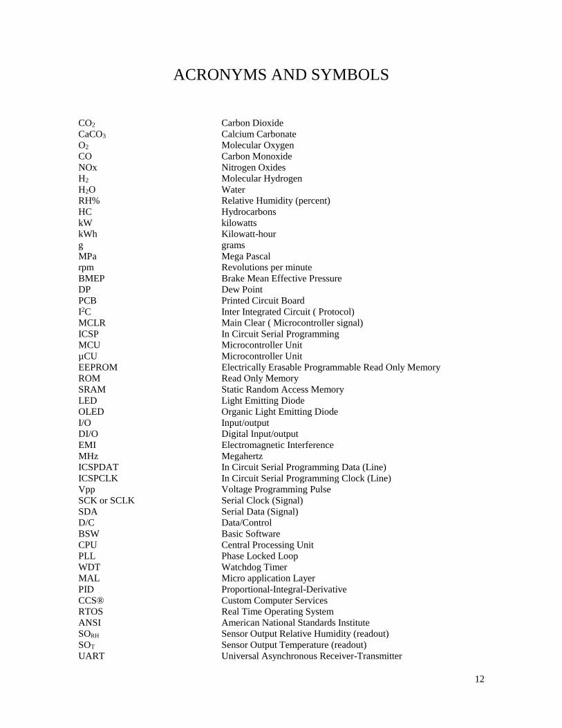
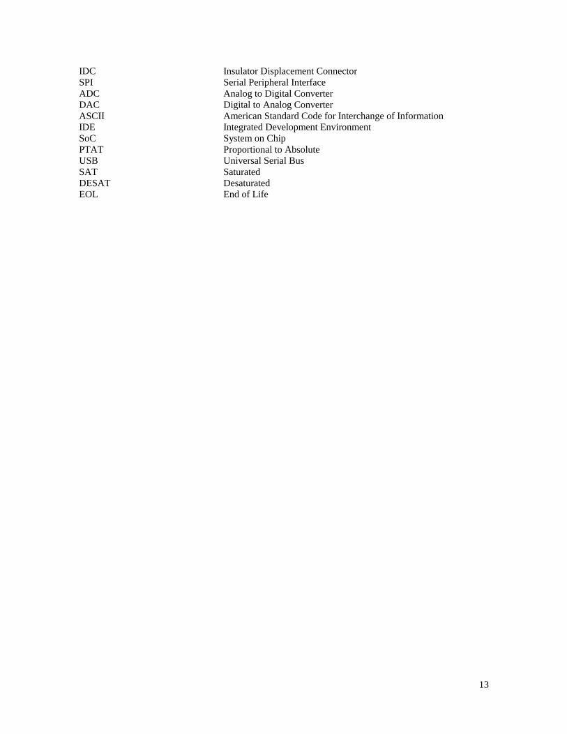
ACRONYMS AND SYMBOLS
CO2 Carbon Dioxide
CaCO3 Calcium Carbonate
O2 Molecular Oxygen
CO Carbon Monoxide
NOx Nitrogen Oxides
H2 Molecular Hydrogen
H2O Water
RH% Relative Humidity (percent)
HC Hydrocarbons
kW kilowatts
kWh Kilowatt-hour
g grams
MPa Mega Pascal
rpm Revolutions per minute
BMEP Brake Mean Effective Pressure
DP Dew Point
PCB Printed Circuit Board
I2C Inter Integrated Circuit ( Protocol)
MCLR Main Clear ( Microcontroller signal)
ICSP In Circuit Serial Programming
MCU Microcontroller Unit
µCU Microcontroller Unit
EEPROM Electrically Erasable Programmable Read Only Memory
ROM Read Only Memory
SRAM Static Random Access Memory
LED Light Emitting Diode
OLED Organic Light Emitting Diode
I/O Input/output
DI/O Digital Input/output
EMI Electromagnetic Interference
MHz Megahertz
ICSPDAT In Circuit Serial Programming Data (Line)
ICSPCLK In Circuit Serial Programming Clock (Line)
Vpp Voltage Programming Pulse
SCK or SCLK Serial Clock (Signal)
SDA Serial Data (Signal)
D/C Data/Control
BSW Basic Software
CPU Central Processing Unit
PLL Phase Locked Loop
WDT Watchdog Timer
MAL Micro application Layer
PID Proportional-Integral-Derivative
CCS® Custom Computer Services
RTOS Real Time Operating System
ANSI American National Standards Institute SORH Sensor Output Relative Humidity (readout)
SOT Sensor Output Temperature (readout)
UART Universal Asynchronous Receiver-Transmitter
13
IDC Insulator Displacement Connector
SPI Serial Peripheral Interface
ADC Analog to Digital Converter
DAC Digital to Analog Converter
ASCII American Standard Code for Interchange of Information
IDE Integrated Development Environment
SoC System on Chip
PTAT Proportional to Absolute
USB Universal Serial Bus
SAT Saturated
DESAT Desaturated
EOL End of Life
14
1. INTRODUCTION
Abstract: This chapter briefly presents the background of this project, the problem definition,
justification, and objectives.

15
In the latest years the ozone layer depletion as well as other serious consequences derived from global
pollution have been an important discussion and action trigger topic across governments, society and
private institutions. This project and this derived thesis is based on existing, and other inspirational
research works aiming to synthesize the fossil fuels emissions, specifically Carbon Dioxide ( CO2) to a
less pollutant as well as recyclable or safely disposable substance such as Calcium Carbonate (CaCo3)
which can have several non-hazardous end uses such as:
Masonry and building
Gardening and non-hazardous/ non-toxic inorganic fertilizers
Landfilling
Painting
Forest bugs plague prevention
Several efforts have been already developed, and some actually under experimental use, mainly for
industrial applications, which worth the value to mention preliminarily:
Bubbling CO2 into salted water ( marine water) in order to allow a chemical reaction to synthesize
gasses into other non-hazardous minerals
Filtering CO2 through a “network” of natural organisms such as algae and urchins (ecchinaccei)
In order to let gasses react with their Calcium shells and absorb most pollutants by synthesizing
them onto CaCO3
Letting CO2 react onto artificial catalytic converters in order to get tem mixed with other minerals.
As can be seen, such solutions are practical for big volume, high infrastructure investments so only focused
to transformation industry, however there is not yet available a lower volume solution for mobile pollutant
systems, such as vehicular combustion systems.
This document will explain in detail the embedded control system development for mobile aftermarket
solution proposal, that can address the treatment of emissions in vehicles, and which can be interfaced to
the chemical and physical means of treating the emissions.
1.1. Background Work
CO2 emissions reduction applied to industry and transformation processes have been a concern during the
last two decades. A research applied to such efforts outcome a series of devices and processes mainly
applied to transformation industry, however the automotive industry still keeps applying the already
known methods that are designed and built along the development lifecycle of a vehicle:

16
+ CATALYTIC CONVERTERS:
A catalytic converter is a device devote to the conversion of toxic gases to a less pollutants products by a
catalytic process, with an oxidation procedure of the hazardous gas. Typically, catalytic converters are
used with engines that use petrol, diesel, and other fossil fuel.
The catalytic converters are quite important nowadays that it is very common information about its
functionality. Typically, there are two types of converters. A two-way converter has two simultaneous
tasks. By the one hand, an oxidation of carbon monoxide to carbon dioxide, represented by the well-known
formula 2CO + O2 → 2CO2. On the other hand, an oxidation process of hydrocarbons to the carbon dioxide
and residual water. This reaction is captured by the formula CxH2x+2 + [(3x+1)/2] O2 → xCO2 + (x+1)
H2O.
A two-way catalytic converter is widely used on engines based on diesel. However, this converter lack of
the ability to control the nitrogen oxidation.
A three-way converters have been designed to overcome the disadvantages of the two-way converters. A
three-way converter has the ability of controlling the emission of nitric oxide and nitrogen dioxide. These
two components contributes to the acid rain and hazardous smog.
As its name suggests, a three-way catalytic converter performs three simultaneous conversion tasks.
Firstly, it makes a reduction process of nitrogen oxides to nitrogen and oxygen (2NOx → xO2 + N2).
Secondly, it does an oxidation of carbon monoxide to carbon dioxide (2CO + O2 → 2CO2). Finally, it
achieves an oxidation of unburnt hydrocarbons to carbon dioxide and water (CxH2x+2 + [(3x+1)/2]O2 →
xCO2 + (x+1)H2O). More information on catalytic converters can be found in Error! Reference source
ot found..
DISADVANTAGES:
Design of catalyzer involves precious or costly metals at some stage of the process ( Rhodium,
Palladium, Cerium, Platinum), which in turn makes the device per se in a costly add-on, and
which recycling process, results not to be not cost effective.
As seen, the device per se, is aimed to reduce both CO and HC emissions. However, the aim of
the global warming solution resides to reduce the CO2 emissions, which in any case are the
residuals for existing catalytic converters (aside of H2O).
As the internal components of a catalyzer have a natural residuals absorption process, there is a
limited life expectancy for a catalyzer which rounds 10 years, so after such period, the user needs
to consider replacing, refurbishing or discarding the catalyzer.
Some minor contaminants of the fuel can progressively change the chemical and red-ox properties
of a catalyzer which in turn makes the catalyzer into a pollutant device. Lead and other heavy
metals contained in any amount in the fuels will lead to this degradation process.
17
The reduction of CO2 emissions is of global interest. Some of the efforts are reflected in patents and
patent applications. An interested reader may refer to the following list to get further information, only
to mention a few:
Keith, C. D., et al. U.S. Patent 3,441,381: "Apparatus for purifying exhaust gases of an
internal combustion engine". 29 April 1969
Lachman, I. M. et al. U.S. Patent 3,885,977: "Anisotropic Cordierite Monolith" (Ceramic
substrate). 5 November 1973
Charles H. Bailey. U.S. Patent 4,094,645: "Combination muffler and catalytic converter
having low backpressure". 13 June 1978
Charles H. Bailey. U.S. Patent 4,250,146: '"Caseless monolithic catalytic converter". 10
February 1981
Srinivasan Gopalakrishnan. GB 2397782: "Process and Synthesizer for Molecular
Engineering of Materials". 13 March 2002
1.2 Justification
The need of an aftermarket and pre-market device to be incorporated on fossil fueled vehicles in
order not to reduce just the CO and HC emissions, but aside CO2, which is the main cause of the
global warming;
The need of a moderated cost CO2 reduction device which can be incorporated a design time on
almost any vehicle in order to be mechanically interfaced to accomplish the intended usage;
And which can be replaced, maintained, disposed and refurbished by user or specialized
workshops
1.3. Problem to be solved
In order to contribute to CO2 reduction from fossil fueled vehicles ,by means of a vehicle internal
device synthesize CO2 emissions ,and ,by a chemical reaction with an alkaline oxide reactive and
condensed water, outcome a nonhazardous sub-product such as CaCO3 which can be safely
disposed or recycled for several uses.
18
1.4. Hypothesis
A device that can be incorporated in a fossil fueled vehicle that shall outcome a nonhazardous sub
product based on the following chemical formula (which aim is to reduce CO2 exhaust emissions):
o CaO + H2O + CO2 CaC03+ H2O
o Where H2O can be condensed from air humidity
o Where CaO can be supplied as a consumable from user
o Where CaCO3 is the sub product obtained from chemical reaction
1.5. Objectives
1.5.1. General Objective:
1.5.1.1 To develop an aftermarket or premarket device to recycle/reduce CO2 emissions from
fossil fueled vehicles, and synthesize exhaust gasses onto a nonhazardous sub product that can be
safely disposed or recycled by user.
1.5.2. Specific Objectives:
1.5.2.1. To design a device that can be fitted by design in the exhaust pipeline in a fossil fueled
vehicle and which significantly reduces the amount of CO2 from combustion emissions,
1.5.2.2.- To design a device that needs only an alkaline oxide reactive, atmospheric air extracted
humidity supply ,and which chemical reactions outcome a disposable product can easily be
retrieved by user.
1.6. Scientific novelty / scientific contribution A device that additionally or in lieu of the traditional catalytic converters, takes the chore of
reducing and/or synthesizing CO2 emissions from automotive exhausts. Actual catalyzers do just
work on CO, NOx and HC emissions,
A device that relies on an embedded control to allow environmental humidity condensing, by
monitoring RH% and controlling a condensing unit ( by calculating the Dew point) such as a
reservoir with a Peltier array that permits extracting humidity from air, thus aimed to be easily
fitted by design otherwise as an aftermarket device to most existing makes of vehicles.
19
2. STATE OF THE TECHNIQUE
Abstract: This chapter briefly presents current developments reported in the literature that are related
with this work.
20
As a context for this project, some works related to the reduction of CO2 emissions are reviewed. The
emphasis is on those works that are closer to the line and objectives of this work. The full reference
to the original work is provided in such a way that further information could be accessed.
2.1 Related Work No.1:
“Reduction of CO2 Emissions for Automotive Systems”
By Junichi Ishii, Minoru Osuga, Takashi Okada, Hideky Miyazaki, Mitsuru Koseki, and Koichiro
Tanikoshi. Hitachi Automotive Systems, Ltd., 2013.
In this work some actual and WIP technologies are described. The state of the art technologies
considered in this paper are:
Vehicle performance by-design technologies: Reduction of Engine losses in power train, hybrid
power train technologies or electrical supply technologies,
Alternative fuels technologies: Ethanol, Propanol, Water electrolysis powering, Bio-fuels, etc.
Infrastructure improvement technologies (ITS)
Fuel consumption optimization techniques: Vapor recirculation, Catalytic converters new
technologies ( however still focused to NOx , HC and COx),
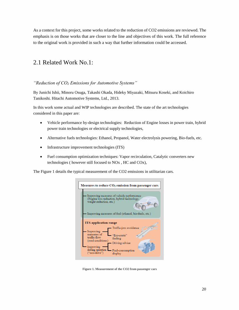
The Figure 1 details the typical measurement of the CO2 emissions in utilitarian cars.
Figure 1. Measurement of the CO2 from passenger cars
21
2.2 Related Work No. 2
“Downsizing of Gasoline Engine: an Efficient Way to Reduce CO2 Emissions”
By P. Leduc, B. Dubar, A. Ranini and G. Monnier. Institut français du pétrole, division
Techniques d’applications énergétiques, 92852 Rueil-Malmaison Cedex – France
Size reduction of the gasoline engine has shown been an efficient way to reduce CO2 emissions. The
next is the abstract information in the cited work:
“Abstract: In order to meet commitments in terms of vehicle CO2 emission reduction for the whole
fleet of cars for the year 2008, engine research and development is today exploring several fields.
From CO2 point of view, gasoline engines suffer from a handicap in comparison to Diesel engines.
Engine (downsizing) appears to be a promising way to improve engine efficiency and is subject to
extensive research. Having a look to the long term, the aim should be to reduce by half the engine
displacement volume.”
2.3 Related Work No. 3
“Assessment of Methanol Synthesis Utilizing Exhaust CO2 for Chemical Storage of Electrical
Energy”
By Liisa K. Rihko-Struckmann, Andreas Peschel, Richard Hanke-Rauschenbach, and Kai
Sundmacher. Max Planck Institute for Dynamics of Complex Technical Systems, and Otto-von-
Guericke University Magdeburg, D-39106 Magdeburg, Germany, Sep 2010.
This work focuses on the production of methanol from residual CO2 is one of the main contribution
of this work. The efficiency of different conversion techniques of the system is analyzed. The
following information could be found in the cited work:
22
“Abstract: This work deals with the thermodynamic and operational boundaries to store electrical
energy chemically. Methanol is considered as a candidate for chemical energy storage.
The production of methanol from exhaust CO2 could be one way to recycle CO2 and lower the global
CO2 emissions in automotive engines. Energetic analysis reveals that exergy losses are most severe
in the parts of the system when electrical energy is converted to chemical, by electrolysis, and when
chemical energy is converted to electrical.”
As could be noticed, there are several efforts to cope the problems related with the pollution reduction,
with a special focus on the CO2 emissions. An interested reader may refer to the provided sources for
more information.

23
3. ARCHITECTURAL DESIGN
Abstract: This chapter describes the architectural design of the solution proposed and the main technical
aspects of the implementation.
24
3.1. LAYOUT ARCHITECTURE
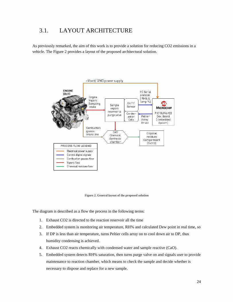
As previously remarked, the aim of this work is to provide a solution for reducing CO2 emissions in a
vehicle. The Figure 2 provides a layout of the proposed architectural solution.
Figure 2. General layout of the proposed solution
The diagram is described as a flow the process in the following terms:
1. Exhaust CO2 is directed to the reaction reservoir all the time
2. Embedded system is monitoring air temperature, RH% and calculated Dew point in real time, so
3. If DP is less than air temperature, turns Peltier cells array on to cool down air to DP, thus
humidity condensing is achieved.
4. Exhaust CO2 reacts chemically with condensed water and sample reactive (CaO).
5. Embedded system detects RH% saturation, then turns purge valve on and signals user to provide
maintenance to reaction chamber, which means to check the sample and decide whether is
necessary to dispose and replace for a new sample.
25
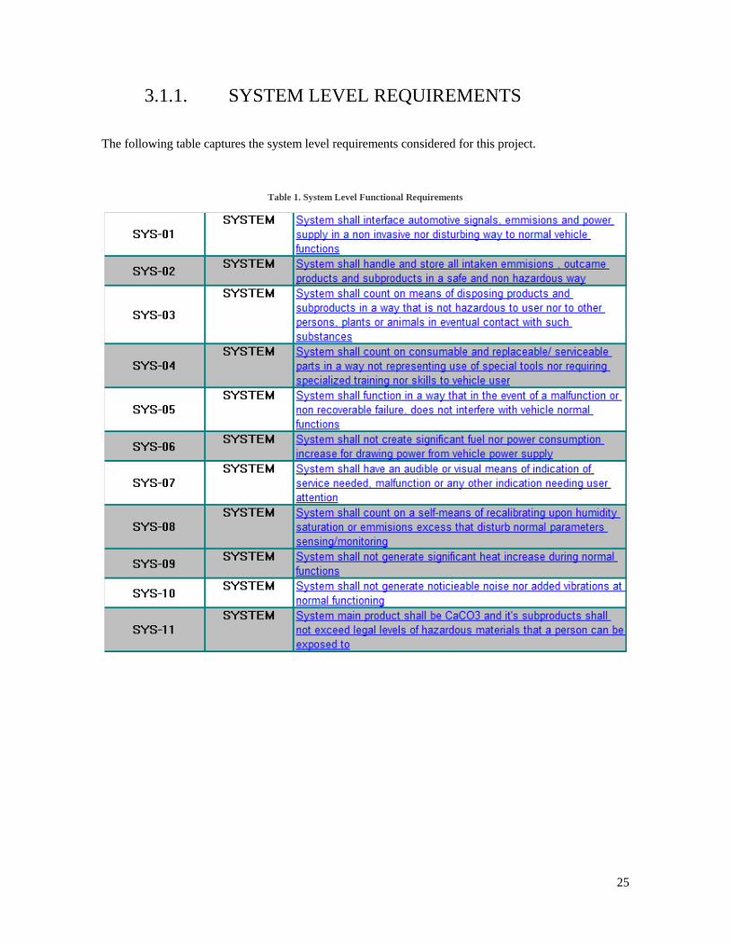
3.1.1. SYSTEM LEVEL REQUIREMENTS
The following table captures the system level requirements considered for this project.
Table 1. System Level Functional Requirements
26
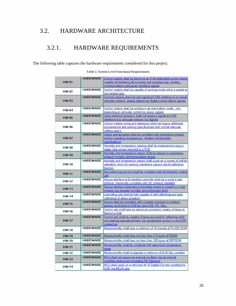
3.2. HARDWARE ARCHITECTURE
3.2.1. HARDWARE REQUIREMENTS
The following table captures the hardware requirements considered for this project.
Table 2. System Level Functional Requirements
27
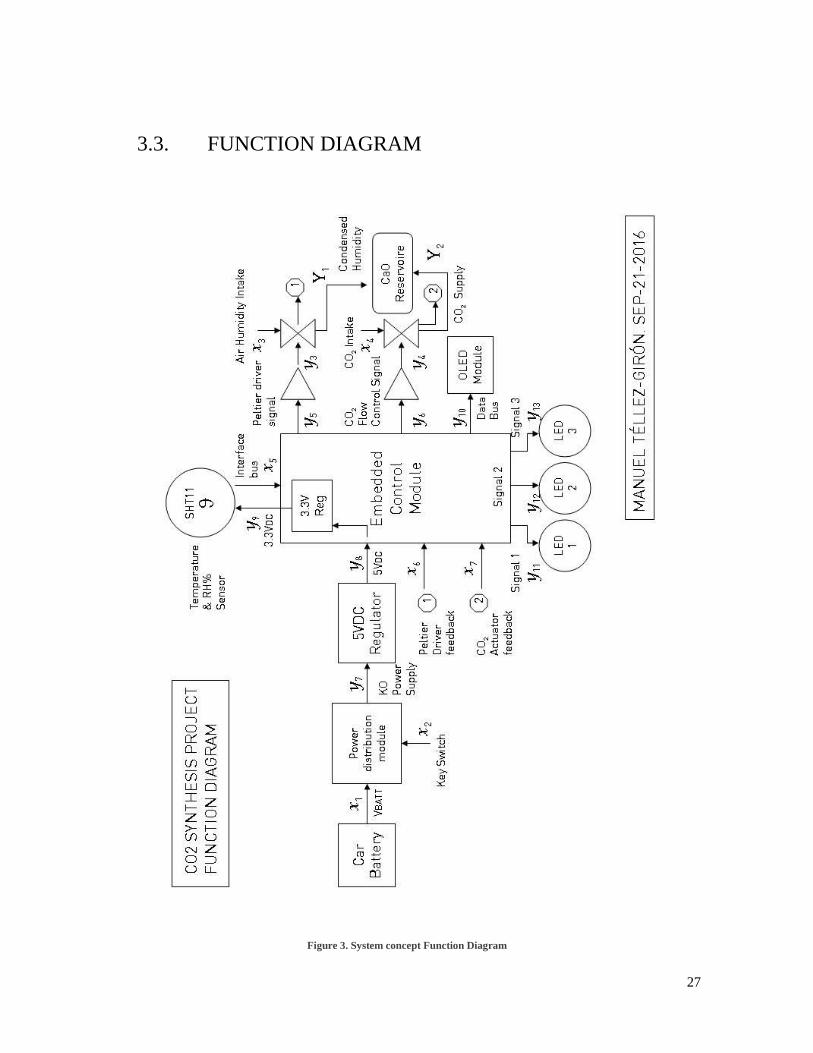
3.3. FUNCTION DIAGRAM
Figure 3. System concept Function Diagram
28
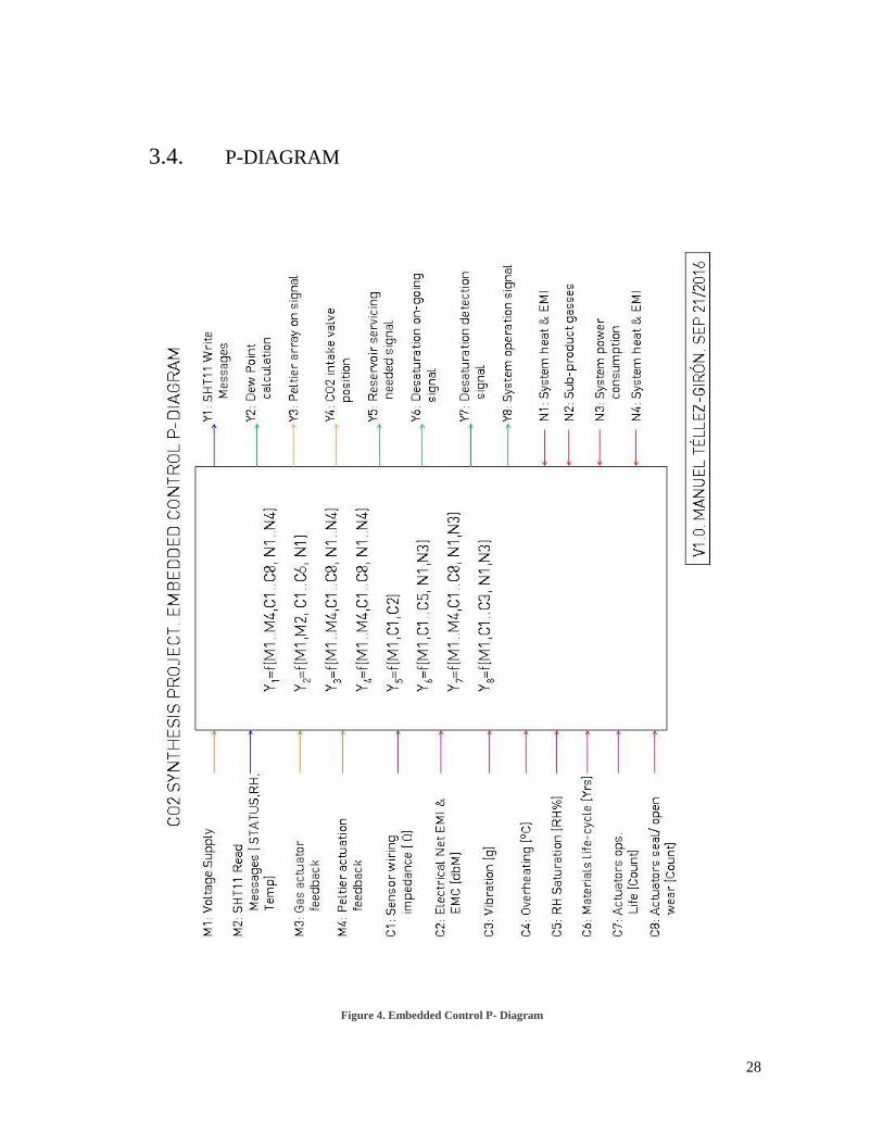
3.4. P-DIAGRAM
Figure 4. Embedded Control P- Diagram

29
3.5. BOUNDARY DIAGRAM
Figure 5. Embedded Control Boundary Diagram
30
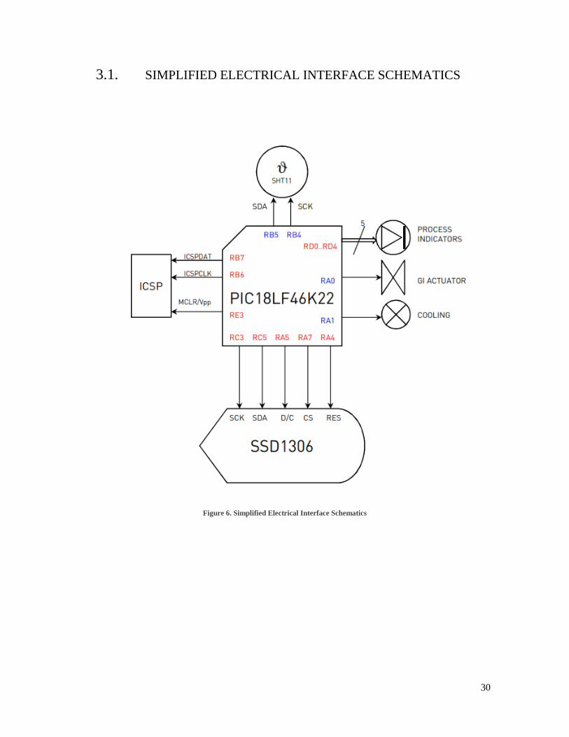
3.1. SIMPLIFIED ELECTRICAL INTERFACE SCHEMATICS
Figure 6. Simplified Electrical Interface Schematics
31
3.2. SOFTWARE ARCHITECTURE
3.2.1. SOFTWARE REQUIREMENTS
The following tables shows the software requirements of this project.
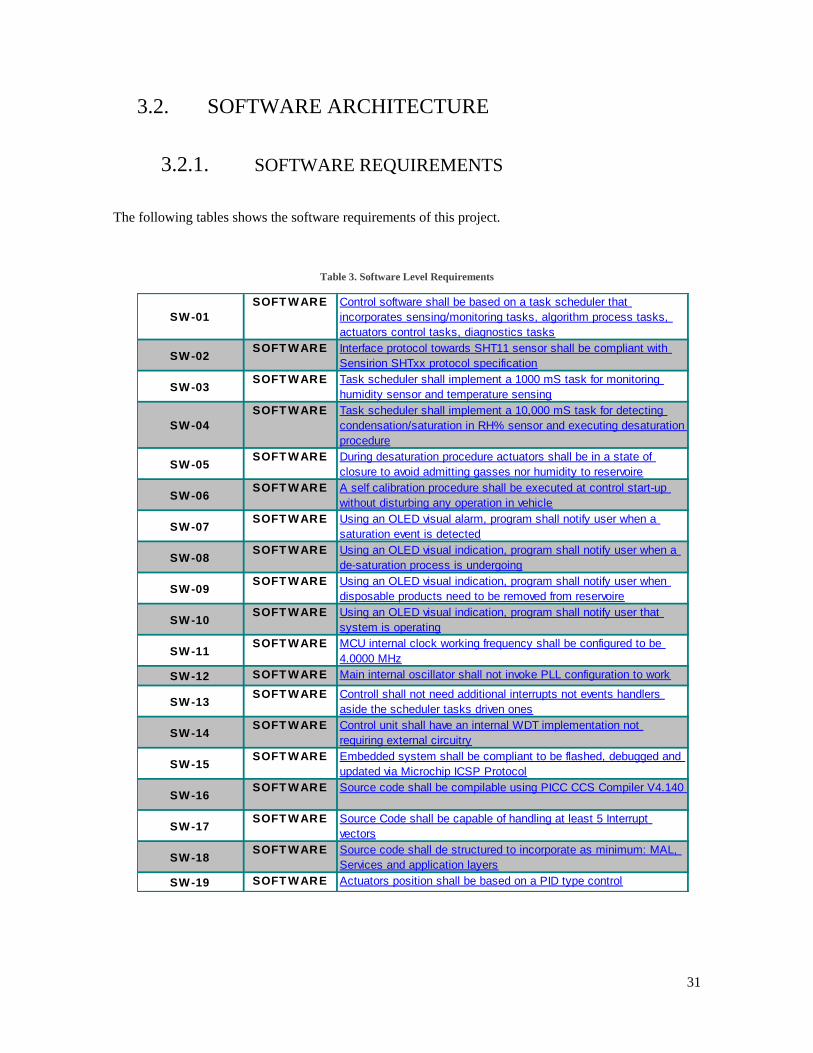
Table 3. Software Level Requirements
SW-01
SOFT WARE Control software shall be based on a task scheduler that
incorporates sensing/monitoring tasks, algorithm process tasks,
actuators control tasks, diagnostics tasks
SW-02SOFT WARE Interface protocol towards SHT11 sensor shall be compliant with
Sensirion SHTxx protocol specification
SW-03SOFT WARE Task scheduler shall implement a 1000 mS task for monitoring
humidity sensor and temperature sensing
SW-04
SOFT WARE Task scheduler shall implement a 10,000 mS task for detecting
condensation/saturation in RH% sensor and executing desaturation
procedure
SW-05SOFT WARE During desaturation procedure actuators shall be in a state of
closure to avoid admitting gasses nor humidity to reservoire
SW-06SOFT WARE A self calibration procedure shall be executed at control start-up
without disturbing any operation in vehicle
SW-07SOFT WARE Using an OLED visual alarm, program shall notify user when a
saturation event is detected
SW-08SOFT WARE Using an OLED visual indication, program shall notify user when a
de-saturation process is undergoing
SW-09SOFT WARE Using an OLED visual indication, program shall notify user when
disposable products need to be removed from reservoire
SW-10SOFT WARE Using an OLED visual indication, program shall notify user that
system is operating
SW-11SOFT WARE MCU internal clock working frequency shall be configured to be
4.0000 MHz
SW-12 SOFT WARE Main internal oscillator shall not invoke PLL configuration to work
SW-13SOFT WARE Controll shall not need additional interrupts not events handlers
aside the scheduler tasks driven ones
SW-14SOFT WARE Control unit shall have an internal WDT implementation not
requiring external circuitry
SW-15SOFT WARE Embedded system shall be compliant to be flashed, debugged and
updated via Microchip ICSP Protocol
SW-16SOFT WARE Source code shall be compilable using PICC CCS Compiler V4.140
SW-17SOFT WARE Source Code shall be capable of handling at least 5 Interrupt
vectors
SW-18SOFT WARE Source code shall de structured to incorporate as minimum: MAL,
Services and application layers
SW-19 SOFT WARE Actuators position shall be based on a PID type control

32
Table 4. Software Level Requirements (cont.)
SW-20 SOFT WARE
Dew point calculation shall be based on the following algorithm
SW-21 SOFT WARE
Program shall scope a linearization/compensation procedure for the
specific operation conditions of the SHT sensor and adhered to the
following formula:
SW-22 SOFT WARE
Program shall apply the following additional Temperature
compensation for operation conditions very above of 25°C
SW-23 SOFT WARE
Temperature conversion from readout shall be obtained using the
follwing formulae:
SW-24SOFT WARE RTOS shall be of pre-emptive type to allow algorithms to handle
semaphors
33
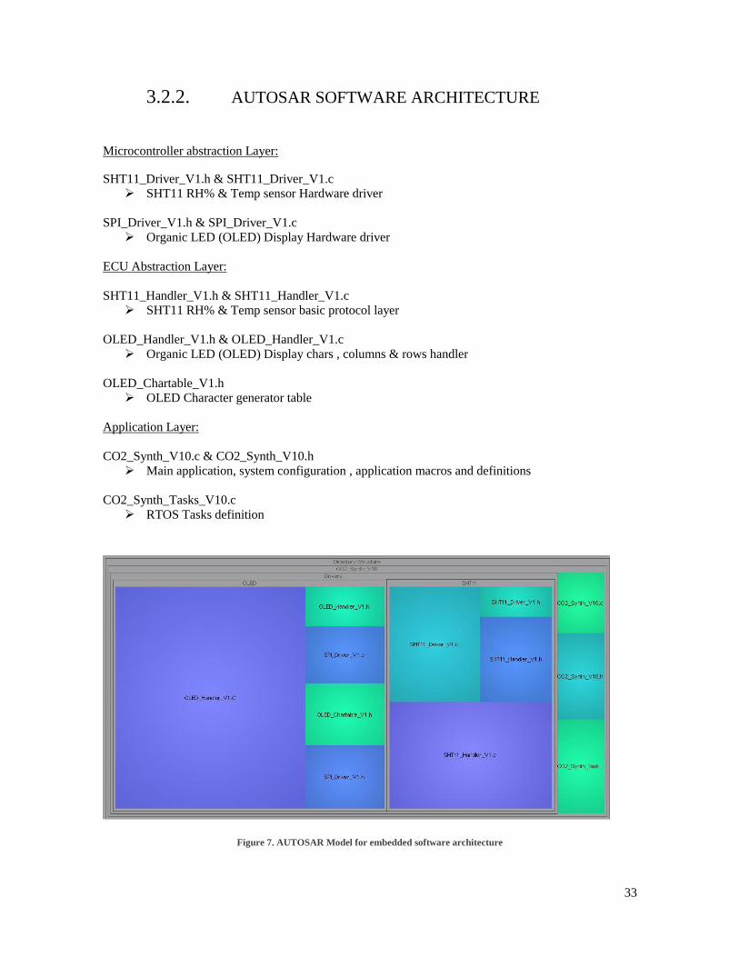
3.2.2. AUTOSAR SOFTWARE ARCHITECTURE
Microcontroller abstraction Layer:
SHT11_Driver_V1.h & SHT11_Driver_V1.c
SHT11 RH% & Temp sensor Hardware driver
SPI_Driver_V1.h & SPI_Driver_V1.c
Organic LED (OLED) Display Hardware driver
ECU Abstraction Layer:
SHT11_Handler_V1.h & SHT11_Handler_V1.c
SHT11 RH% & Temp sensor basic protocol layer
OLED_Handler_V1.h & OLED_Handler_V1.c
Organic LED (OLED) Display chars , columns & rows handler
OLED_Chartable_V1.h
OLED Character generator table
Application Layer:
CO2_Synth_V10.c & CO2_Synth_V10.h
Main application, system configuration , application macros and definitions
CO2_Synth_Tasks_V10.c
RTOS Tasks definition
Figure 7. AUTOSAR Model for embedded software architecture
34
3.2.3. BUTTERFLY DIAGRAM SOFTWARE
ARCHITECTURE
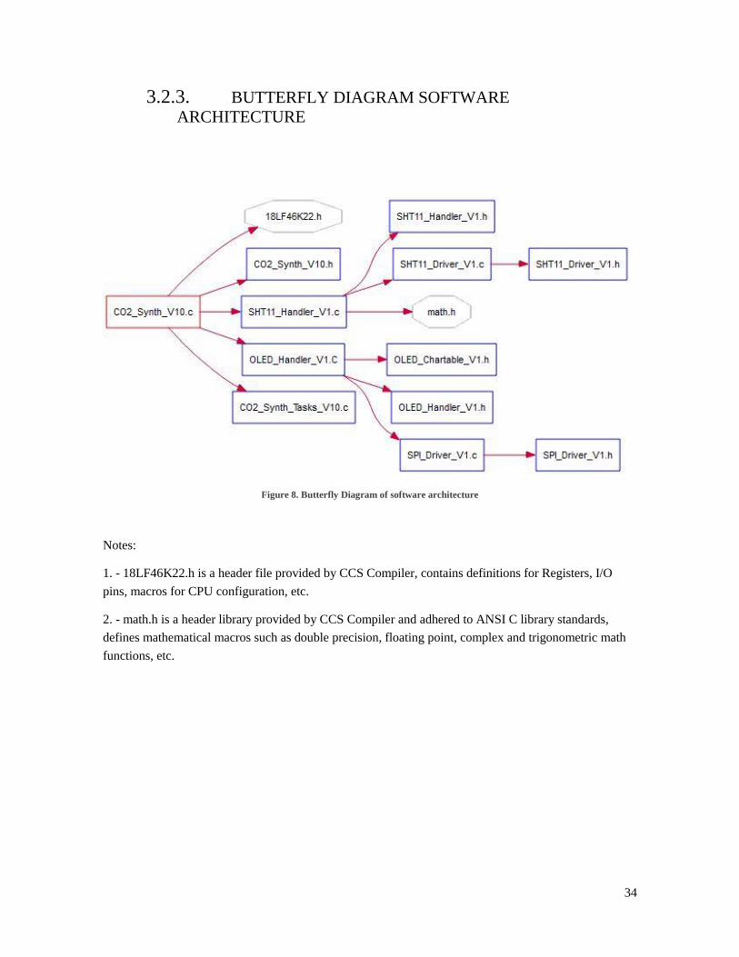
Figure 8. Butterfly Diagram of software architecture
Notes:
1. - 18LF46K22.h is a header file provided by CCS Compiler, contains definitions for Registers, I/O
pins, macros for CPU configuration, etc.
2. - math.h is a header library provided by CCS Compiler and adhered to ANSI C library standards,
defines mathematical macros such as double precision, floating point, complex and trigonometric math
functions, etc.
35
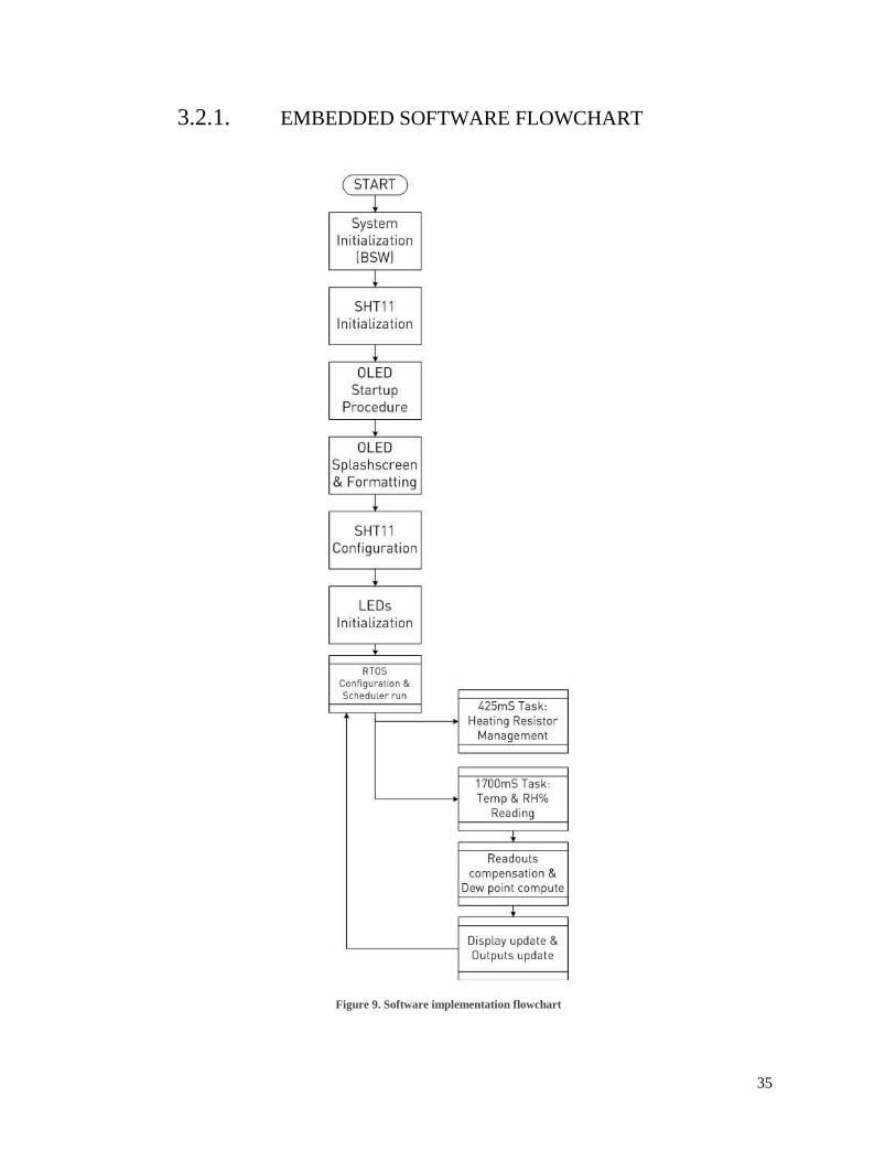
3.2.1. EMBEDDED SOFTWARE FLOWCHART
Figure 9. Software implementation flowchart

36
4. IMPLEMENTATION
Abstract: This chapter describes the main aspects of the implementations developed in this work. It
describes the development tools as well as the integrated development environment, compilation tools and
sensors interfacing.
37
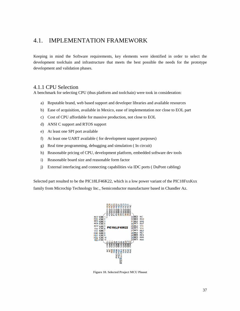
4.1. IMPLEMENTATION FRAMEWORK
Keeping in mind the Software requirements, key elements were identified in order to select the
development toolchain and infrastructure that meets the best possible the needs for the prototype
development and validation phases.
4.1.1 CPU Selection A benchmark for selecting CPU (thus platform and toolchain) were took in consideration:
a) Reputable brand, web based support and developer libraries and available resources
b) Ease of acquisition, available in Mexico, ease of implementation nor close to EOL part
c) Cost of CPU affordable for massive production, not close to EOL
d) ANSI C support and RTOS support
e) At least one SPI port available
f) At least one UART available ( for development support purposes)
g) Real time programming, debugging and simulation ( In circuit)
h) Reasonable pricing of CPU, development platform, embedded software dev tools
i) Reasonable board size and reasonable form factor
j) External interfacing and connecting capabilities via IDC ports ( DuPont cabling)
Selected part resulted to be the PIC18LF46K22, which is a low power variant of the PIC18FxxKxx
family from Microchip Technology Inc., Semiconductor manufacturer based in Chandler Az.
Figure 10. Selected Project MCU Pinout

38
4.1.2 Development hardware selection
Based on previous CPU criteria the selected development board is the DM164134 which incorporates an
on-board OLED display, a 32KHz tuning fork oscillator, ADC and DAC circuitry, Low resolution
temperature sensor, auxiliary LED indicators and pushbuttons, current monitor and on-board voltage
regulator.
As usual in Microchip development boards, the platform incorporated an ICSP interface to let real time
programming and debugging from the IDE using the standard development tools such as MPLAB
ICD 2, ICD3 or PickIT3
This board incorporates aside 0.1 inch pitch female connectors compatible with DuPont style prototyping
connectors, so it is available to interface with external boards or prototyping boards by using a simple
insert type wiring.
For this project purposes, an external prototyping board where the SHT11 sensor was inserted, was the
choice in order to keep prototyping modularity.
Figure 11. Microchip Development board (DM164134)

39
4.1.3 Integrated Development Environment (IDE)
Since a Microchip part was selected, an adequate IDE is needed. Microchip base development IDE is the
MPLAB platform thus, such platform was selected. The latest IDE version (as of September 2016) is the
MPLABX V3.40, however does not run appropriately on all computing environments/ OS, so a rollback
to MPLAB V8.90 was decided in order to provide the most flexibility during the development cycle.
Basic platform incorporates an editor, an integrated assembler (MPASM) and simulator. MPLAB natively
interfaces ICSP protocol based tools such as ICD2, ICD3 and Pickit3.
Figure 12. MPLAB IDE V8.90 Screenshot
40
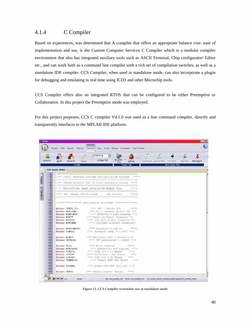
4.1.4 C Compiler
Based on experiences, was determined that A compiler that offers an appropriate balance cost- ease of
implementation and use, is the Custom Computer Services C Compiler which is a modular compiler
environment that also has integrated auxiliary tools such as ASCII Terminal, Chip configurator/ Editor
etc., and can work both as a command line compiler with a rich set of compilation switches, as well as a
standalone IDE compiler. CCS Compiler, when used in standalone mode, can also incorporate a plugin
for debugging and emulating in real time using ICD3 and other Microchip tools.
CCS Compiler offers also an integrated RTOS that can be configured to be either Preemptive or
Collaborative. In this project the Preemptive mode was employed.
For this project purposes, CCS C compiler V4.1.0 was used as a line command compiler, directly and
transparently interfaces to the MPLAB IDE platform.
Figure 13. CCS Compiler screenshot run at standalone mode
41
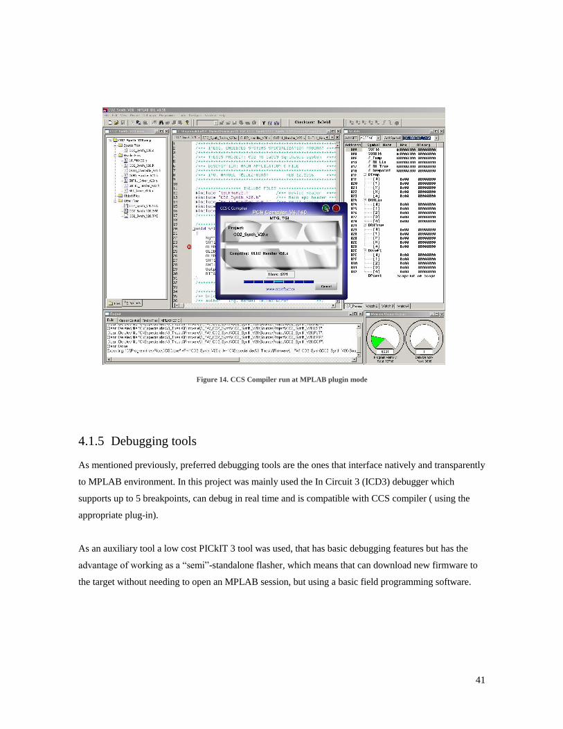
Figure 14. CCS Compiler run at MPLAB plugin mode
4.1.5 Debugging tools
As mentioned previously, preferred debugging tools are the ones that interface natively and transparently
to MPLAB environment. In this project was mainly used the In Circuit 3 (ICD3) debugger which
supports up to 5 breakpoints, can debug in real time and is compatible with CCS compiler ( using the
appropriate plug-in).
As an auxiliary tool a low cost PICkIT 3 tool was used, that has basic debugging features but has the
advantage of working as a “semi”-standalone flasher, which means that can download new firmware to
the target without needing to open an MPLAB session, but using a basic field programming software.
42
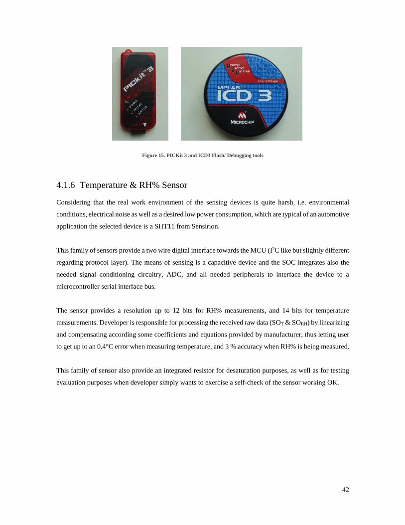
Figure 15. PICKit 3 and ICD3 Flash/ Debugging tools
4.1.6 Temperature & RH% Sensor
Considering that the real work environment of the sensing devices is quite harsh, i.e. environmental
conditions, electrical noise as well as a desired low power consumption, which are typical of an automotive
application the selected device is a SHT11 from Sensirion.
This family of sensors provide a two wire digital interface towards the MCU (I2C like but slightly different
regarding protocol layer). The means of sensing is a capacitive device and the SOC integrates also the
needed signal conditioning circuitry, ADC, and all needed peripherals to interface the device to a
microcontroller serial interface bus.
The sensor provides a resolution up to 12 bits for RH% measurements, and 14 bits for temperature
measurements. Developer is responsible for processing the received raw data (SOT & SORH) by linearizing
and compensating according some coefficients and equations provided by manufacturer, thus letting user
to get up to an 0.4°C error when measuring temperature, and 3 % accuracy when RH% is being measured.
This family of sensor also provide an integrated resistor for desaturation purposes, as well as for testing
evaluation purposes when developer simply wants to exercise a self-check of the sensor working OK.
43
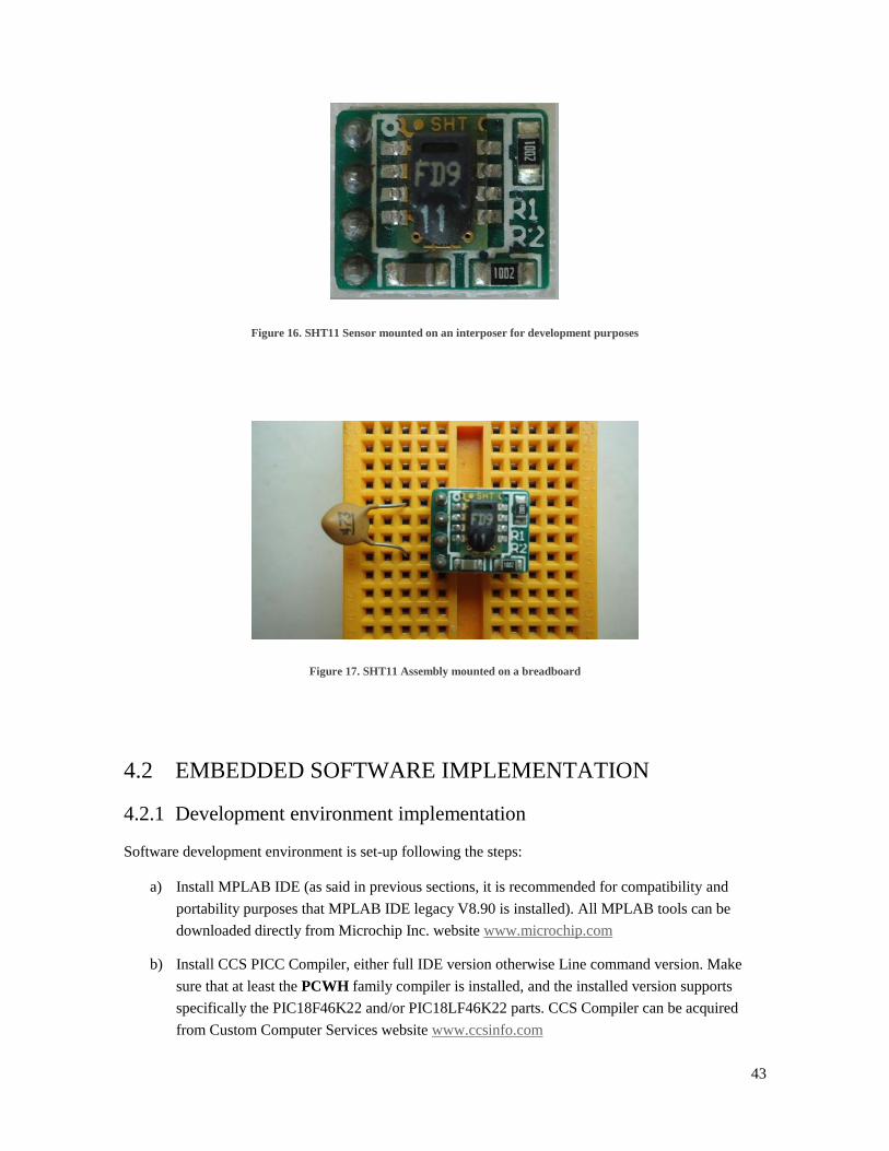
Figure 16. SHT11 Sensor mounted on an interposer for development purposes
Figure 17. SHT11 Assembly mounted on a breadboard
4.2 EMBEDDED SOFTWARE IMPLEMENTATION
4.2.1 Development environment implementation
Software development environment is set-up following the steps:
a) Install MPLAB IDE (as said in previous sections, it is recommended for compatibility and
portability purposes that MPLAB IDE legacy V8.90 is installed). All MPLAB tools can be
downloaded directly from Microchip Inc. website www.microchip.com
b) Install CCS PICC Compiler, either full IDE version otherwise Line command version. Make
sure that at least the PCWH family compiler is installed, and the installed version supports
specifically the PIC18F46K22 and/or PIC18LF46K22 parts. CCS Compiler can be acquired
from Custom Computer Services website www.ccsinfo.com

44
c) Install MPLAB IDE Plug in also from CCS Inc., make sure that plug in is installed prior to
creating an MPLAB project based for the first time
d) Install MPLAB ICD3 Plug in also from CCS Inc., make sure that plug in is installed prior to
creating an MPLAB project based for the first time whether developer will use any MPLAB
commanded development tools ( ICD2, ICD3, Pickit3, Real ICE, MP3 etc).
e) Create a new project in MPLAB IDE selecting 18LF46K22 as CPU, and CCS suite (PICC.exe)
as tool suite.
f) If reusing software modules, make sure are selected when using the browser dialog window to
select files to be included, otherwise simply let MPLAB create the project with no source files
included, and add them later to project
g) In an open MPLAB IDE session configure, inside Project configuration menu, the linker path,
the include files path and intermediate files path (object files). Make sure that linker file is the
one provided by CCS Compiler and not the one from MPLAB installation.
h) Make sure that when using an ICD or a PICKit3 device as programmer, IDE is set as
RELEASE, otherwise in debugging mode DEBUG should be selected
i) Make sure that, even though developer can have many tabs with source files open in a project,
the only c source file in the Project Manager File tree is the main.c file, otherwise the build will
contain errors and will not be completed. Header (.h) files, linker files (.lkr), assembly files and
other files have no limitations to be included in Project manager tree window.
j) Make sure also that main.c file calls CPU header file to the CCS provided one and not the one
provided by MPLAB IDE Installation
k) When using ICD3 as programmer debugger, remember that target board can be powered from
debugger only if an external Power supply is attached to ICD3. For PICKit3 case, it is not
necessary to attach an external power supply to power the target from PICKit3 while power
demand is below limits. Also check always the right VCC level upon CPU selection.
4.2.1 Embedded software sections implementation
4.2.1.1 Main file (CO2_Synth_V20.c)
The main file is the axis for the application layer of embedded software. It contains the following
elements:
a) Include handler level modules (.c) and headers (.h) for the main application layer
b) CPU & Peripherals initialization calls
c) RTOS Startup instructions & configuration
45
4.2.1.2 Main header file (CO2_Synth_V20.h)
This file will provide configuration for the following elements:
a) Program-time (flash) FUSES configuration such as: Oscillator configuration, Watchdog timer
configuration, Memory zones protection configuration, Capture- Compare I/Os mapping,
Brownout configuration, etc.
b) Application Macros & defines: I/Os alias
4.2.1.3 Driver for SHT11 Sensor (SHT11_Driver_V20.c/ SHT11_Driver_V20.h)
These files provide the basic software layer interface to control the SPI communications to and from
SHT11 sensor.
4.2.1.4 SPI interface (4-wire) for SSD1306 chip (SPI_Driver_V20.c/ SPI_Driver_V20.h)
These files provide the basic software layer to interface the 4 line SPI bus to communicate to and from
OLED controller chip (SSD1306).
4.2.1.5 Handler for SHT11 Sensor (SHT11_Handler_V20.c/ SHT11_Handler_V20.h)
These files provide the handler routines having SHT11 raw data as input:
a) Sensor SPI port initialization and configuration calls
b) SPI port Command processor
c) Temperature & Humidity readout management
d) Temperature & Humidity data compensation, linearization and conversion to readable
characters
e) Dew point calculation
f) Floating point management routines
4.2.1.6 Handler for OLED display (OLED_Handler_V20.c/ OLED_Handler_V20.h)
These files provide the handler routines for displaying updated data and status onto OLED display.
4.2.1.7 OLED Display character map (OLED_Chartable_V20.h)
This file provides the dot matrix map for displaying readable characters in OLED Display
46
4.2.1.8 RTOS Tasks definition (CO2_Synth_Tasks_V20.c)
This file provides the code for each one of the implemented RTOS Tasks (425mS & 1700mS);
a) 425mS: Forced Heater handler
b) 1700mS: Periodic data samplig process
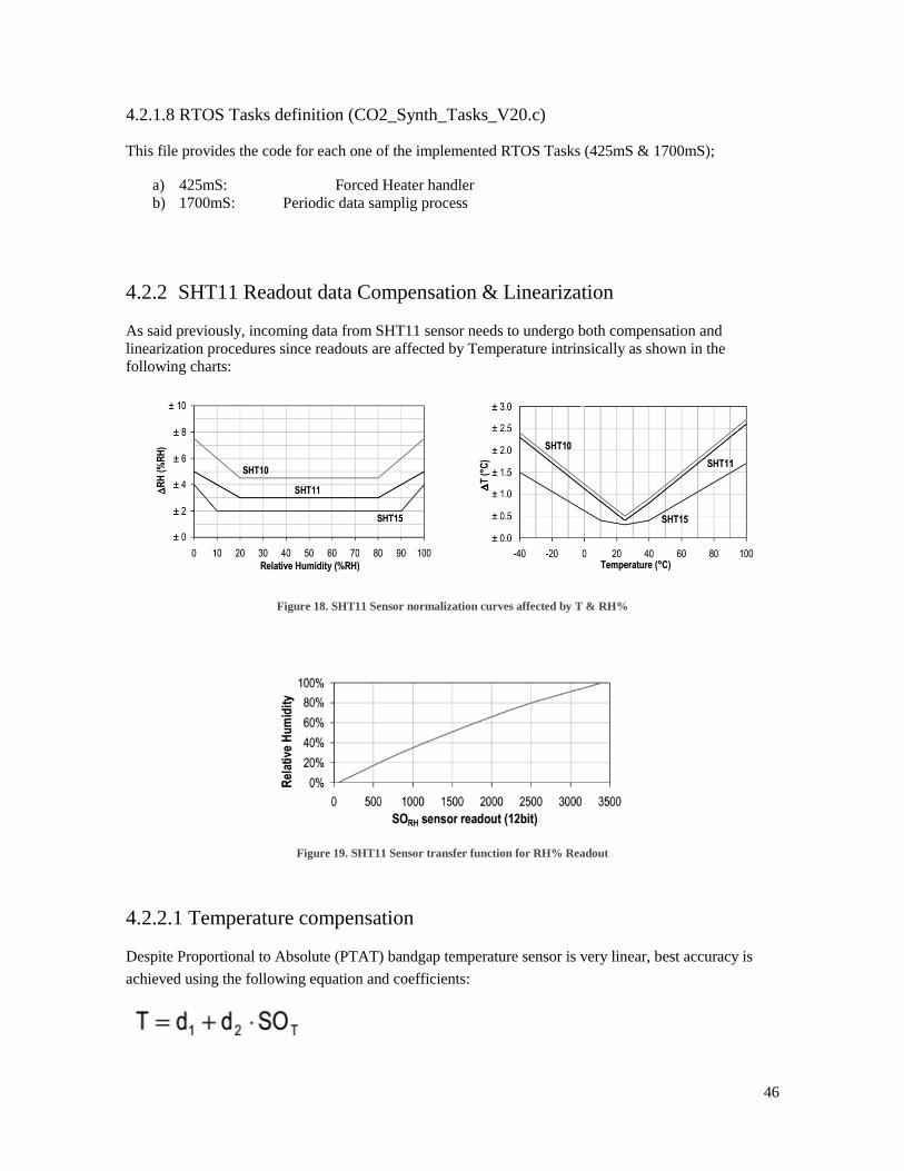
4.2.2 SHT11 Readout data Compensation & Linearization
As said previously, incoming data from SHT11 sensor needs to undergo both compensation and
linearization procedures since readouts are affected by Temperature intrinsically as shown in the
following charts:
Figure 18. SHT11 Sensor normalization curves affected by T & RH%
Figure 19. SHT11 Sensor transfer function for RH% Readout
4.2.2.1 Temperature compensation
Despite Proportional to Absolute (PTAT) bandgap temperature sensor is very linear, best accuracy is
achieved using the following equation and coefficients:

47
Where:
T= Compensated Temperature readout
SOT= “Raw” Sensor temperature readout
d1= Compensation offset depending on Voltage supply to sensor
d2= Compensation slope coefficient depending on readout selected resolution
Table 5. SHT11 Temperature compensation coefficients upon VDD and resolution
4.2.2.2 RH% linearization
Table 6. SHT11 RH% Linearization coefficients upon resolution
Where:
RHlinear= Linearized RH% Readout
SORH= “Raw” Sensor RH% readout
C1= Compensation offset depending on readout selected resolution
C2= Compensation slope linear coefficient depending on readout selected resolution
C3= Compensation slope quadratic coefficient depending on readout selected resolution
48
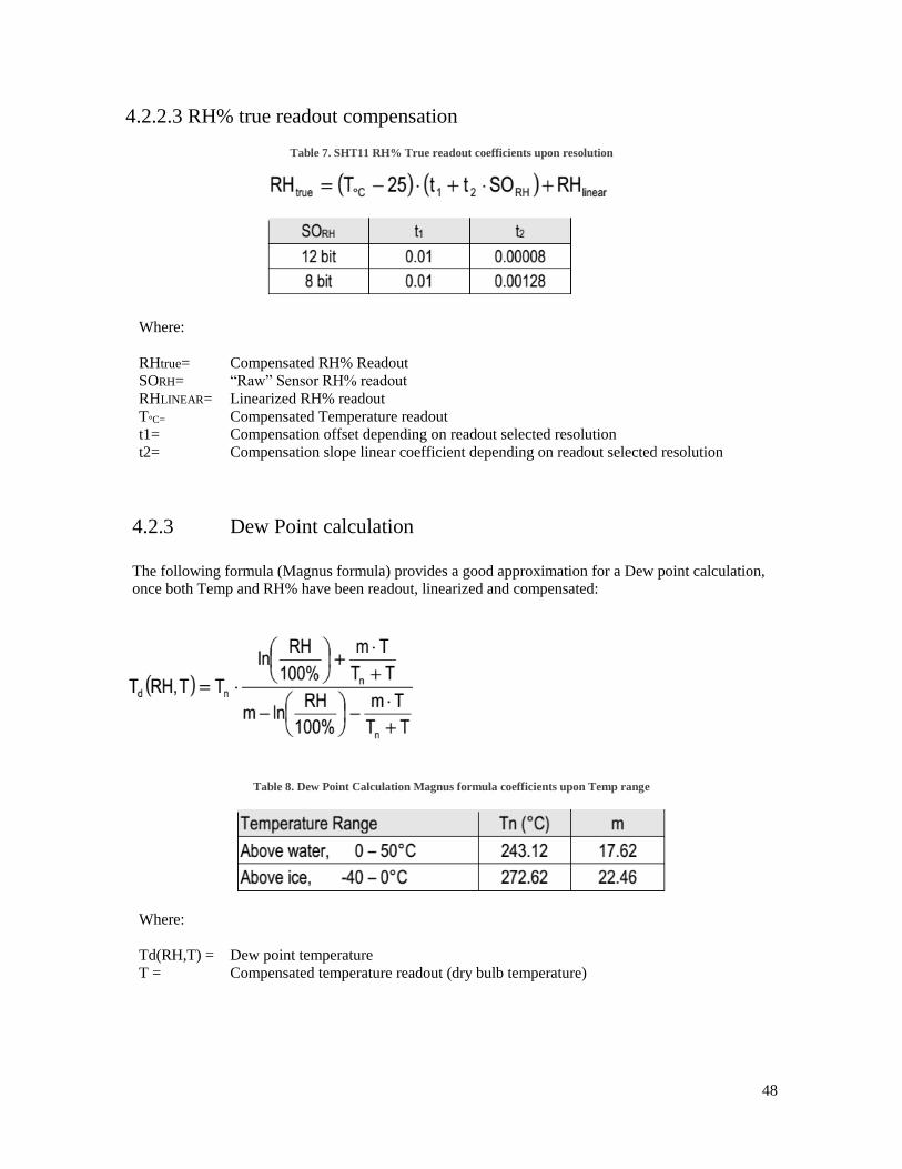
4.2.2.3 RH% true readout compensation
Table 7. SHT11 RH% True readout coefficients upon resolution
Where:
RHtrue= Compensated RH% Readout
SORH= “Raw” Sensor RH% readout
RHLINEAR= Linearized RH% readout
T°C= Compensated Temperature readout
t1= Compensation offset depending on readout selected resolution
t2= Compensation slope linear coefficient depending on readout selected resolution
4.2.3 Dew Point calculation
The following formula (Magnus formula) provides a good approximation for a Dew point calculation,
once both Temp and RH% have been readout, linearized and compensated:
Table 8. Dew Point Calculation Magnus formula coefficients upon Temp range
Where:
Td(RH,T) = Dew point temperature
T = Compensated temperature readout (dry bulb temperature)

49
5. RESULTS
50
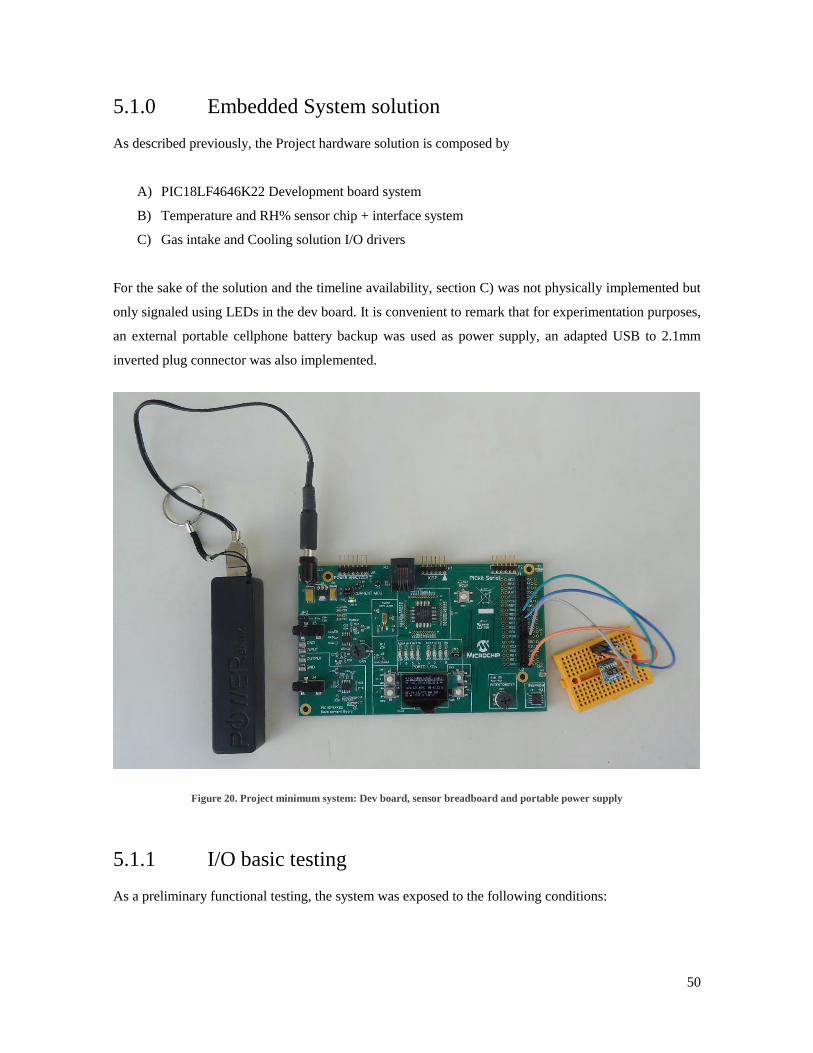
5.1.0 Embedded System solution
As described previously, the Project hardware solution is composed by
A) PIC18LF4646K22 Development board system
B) Temperature and RH% sensor chip + interface system
C) Gas intake and Cooling solution I/O drivers
For the sake of the solution and the timeline availability, section C) was not physically implemented but
only signaled using LEDs in the dev board. It is convenient to remark that for experimentation purposes,
an external portable cellphone battery backup was used as power supply, an adapted USB to 2.1mm
inverted plug connector was also implemented.
Figure 20. Project minimum system: Dev board, sensor breadboard and portable power supply
5.1.1 I/O basic testing
As a preliminary functional testing, the system was exposed to the following conditions:

51
A) Measuring room temperature and RH% at any given date/ time. Expected results are
0°C < Temp < 42°C (baseline is temp in Guadalajara, Jalisco México)
20% < RH < 80%
No desaturation indication
No forced desaturation activation
B) Soaking system inside a freezer for 10 mins and taking immediate readings and I/O state.
Expected results are:
-10°C < Temp < 5°C
20% < RH < 80%
If RH > 85%, desaturation indication and activation shall be true
C) Waiting other 30 mins to await for system to complete the desaturation cycle and reach again
the room conditions
D) Forced heating using INT0 shall provoke that system starts reading out temperature increase
aside RH% decrease
Figure 21. System operating “soaked” at room Temp and room RH% (baseline)
Figure 22. System operating as soon as removed from freezer: Heater ON, SAT indicator ON
52
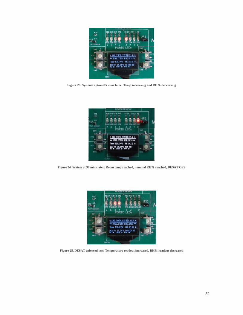
Figure 23. System captured 5 mins later: Temp increasing and RH% decreasing
Figure 24. System at 30 mins later: Room temp reached, nominal RH% reached, DESAT OFF
Figure 25. DESAT enforced test: Temperature readout increased, RH% readout decreased
53
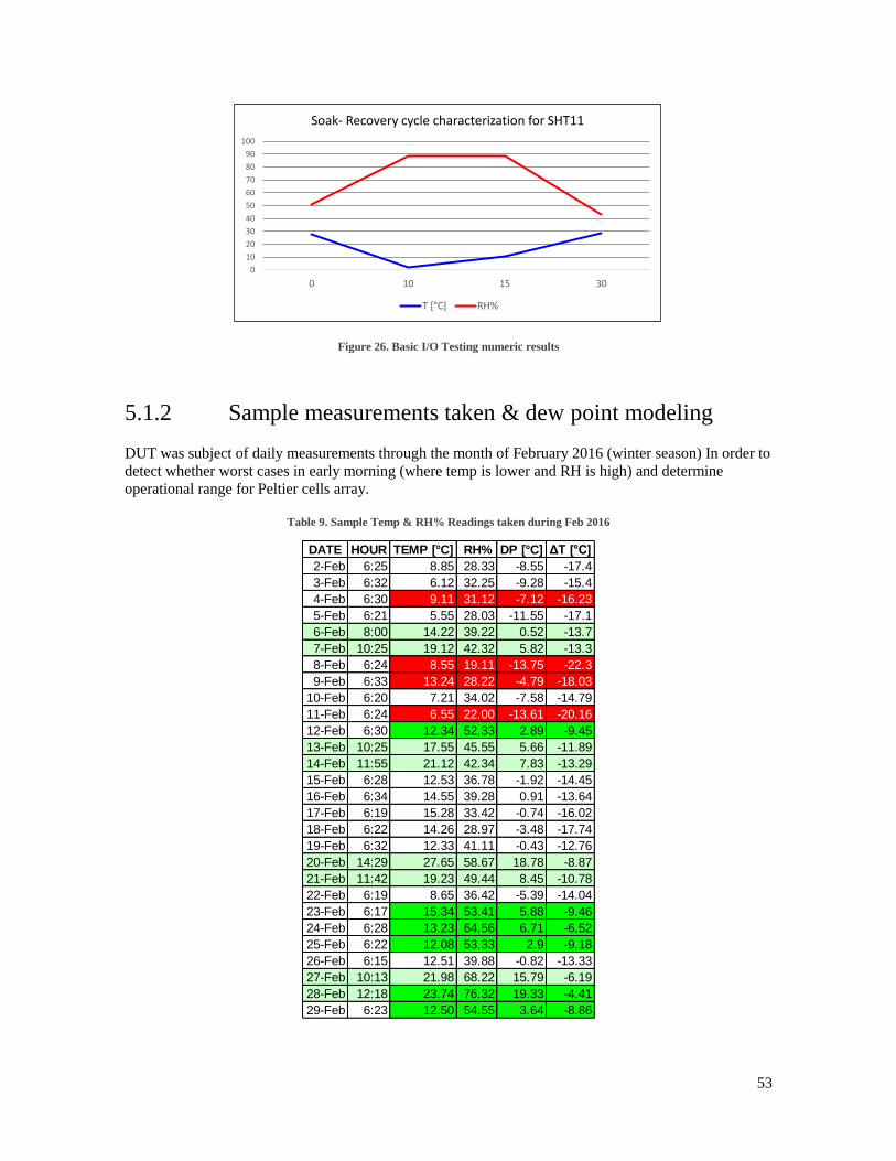
Figure 26. Basic I/O Testing numeric results
5.1.2 Sample measurements taken & dew point modeling
DUT was subject of daily measurements through the month of February 2016 (winter season) In order to
detect whether worst cases in early morning (where temp is lower and RH is high) and determine
operational range for Peltier cells array.
Table 9. Sample Temp & RH% Readings taken during Feb 2016
0
10
20
30
40
50
60
70
80
90
100
0 10 15 30
Soak- Recovery cycle characterization for SHT11
T [°C] RH%
DATE HOUR TEMP [°C] RH% DP [°C] ΔT [°C]
2-Feb 6:25 8.85 28.33 -8.55 -17.4
3-Feb 6:32 6.12 32.25 -9.28 -15.4
4-Feb 6:30 9.11 31.12 -7.12 -16.23
5-Feb 6:21 5.55 28.03 -11.55 -17.1
6-Feb 8:00 14.22 39.22 0.52 -13.7
7-Feb 10:25 19.12 42.32 5.82 -13.3
8-Feb 6:24 8.55 19.11 -13.75 -22.3
9-Feb 6:33 13.24 28.22 -4.79 -18.03
10-Feb 6:20 7.21 34.02 -7.58 -14.79
11-Feb 6:24 6.55 22.00 -13.61 -20.16
12-Feb 6:30 12.34 52.33 2.89 -9.45
13-Feb 10:25 17.55 45.55 5.66 -11.89
14-Feb 11:55 21.12 42.34 7.83 -13.29
15-Feb 6:28 12.53 36.78 -1.92 -14.45
16-Feb 6:34 14.55 39.28 0.91 -13.64
17-Feb 6:19 15.28 33.42 -0.74 -16.02
18-Feb 6:22 14.26 28.97 -3.48 -17.74
19-Feb 6:32 12.33 41.11 -0.43 -12.76
20-Feb 14:29 27.65 58.67 18.78 -8.87
21-Feb 11:42 19.23 49.44 8.45 -10.78
22-Feb 6:19 8.65 36.42 -5.39 -14.04
23-Feb 6:17 15.34 53.41 5.88 -9.46
24-Feb 6:28 13.23 64.56 6.71 -6.52
25-Feb 6:22 12.08 53.33 2.9 -9.18
26-Feb 6:15 12.51 39.88 -0.82 -13.33
27-Feb 10:13 21.98 68.22 15.79 -6.19
28-Feb 12:18 23.74 76.32 19.33 -4.41
29-Feb 6:23 12.50 54.55 3.64 -8.86

54
Results follow:
Where:
DP = Calculated Dew point to enforce humidity condensation at sampled weather conditions
ΔT = Temperature decrease needed to reach the calculated Dew point.
Figure 27. Sample readouts plot: February 2016
Figure 28. Calculated Dew point and needed temperature deltas for sample measurements
0
10
20
30
40
50
60
70
80
2-Fe
b
3-Fe
b
4-Fe
b
5-Fe
b
6-Fe
b
7-Fe
b
8-Fe
b
9-Fe
b
10-F
eb
11-F
eb
12-F
eb
13-F
eb
14-F
eb
15-F
eb
16-F
eb
17-F
eb
18-F
eb
19-F
eb
20-F
eb
21-F
eb
22-F
eb
23-F
eb
24-F
eb
25-F
eb
26-F
eb
27-F
eb
28-F
eb
29-F
eb
Measured Parameters: Feb 2016
Temp °C
RH%
-24
-20
-16
-12
-8
-4
0
4
8
12
16
20
24
2-Fe
b
3-Fe
b
4-Fe
b
5-Fe
b
6-Fe
b
7-Fe
b
8-Fe
b
9-Fe
b
10-F
eb
11-F
eb
12-F
eb
13-F
eb
14-F
eb
15-F
eb
16-F
eb
17-F
eb
18-F
eb
19-F
eb
20-F
eb
21-F
eb
22-F
eb
23-F
eb
24-F
eb
25-F
eb
26-F
eb
27-F
eb
28-F
eb
29-F
eb
Dew Point & Temp Delta: Feb 2016
DP [°C]
ΔT [°C]
55
6. CONCLUSIONS
56
6.1. Conclusions
6.1.1.- Original scope of the project was to reach the stage of a working functional prototype,
including, potentially, a way of getting electrical power without intrusion such as implementing a
solar panel as an external accessory. It was unfeasible to accomplish the full envisioned scope due to
some factors that were not identified at the start of the project, however this shortfall provided some
learning for future project planning exercises. Some of the factors hence listed:
a) High cost of physical components such as the Peltier cells array otherwise another cooling
solution for enforcing a dew point, Gas intake valve, chemical reservoir, etc.
b) Restrictions on the development board to provide the sufficient power to drive actuators:
Valves typically require 2-5 amps to excite DC coils; sized Peltier cells require more than 2
amps to get energized, etc.; thus a non-scoped power driver section needs to be designed and
implemented.
c) It got unfeasible to plan on a non-intrusive power supply system due to the big size of the
solar panels that would be needed to provide the amount of power needed by system.
d) Chemical reservoir deserves a further detailed study, design and modeling of the solution
in order to produce a working prototype, aside thinking on a solution that with minor
modifications can be implemented as an aftermarket solution for vehicles, otherwise a factory-
time solution.
6.1.2. - In the original concept, just a cold-producing device was considered, thus, a “fixed” single
driver connection to the Peltier cells array was considered, and a simple ON/OFF Control
scenario was envisioned. After doing the sampling of temperature and RH% readouts in the
month of February, was found out that when the temperature falls below the water freezing
point and, by hysteresis below triple point (4°C), a Cooling device does no longer work to
enforce humidity condensation, so the solution in turn is a reverse connected Peltier cell
otherwise now a heating device (such as a resistor) in order to reciprocally enforce a dew
point in the humidity reservoir. This means a future new sizing of temperature management
solution, aside a polarity inverting scheme in the development board (i.e. two driver outputs
instead of a single one). Aside implementing an hysteresis algorithm in software in order to
let the system produce heat between a DP less equal 0°C and 4°C, and cold above such point.
57
6.1.3. - Several dew point calculation methods were found. Actually, however, the best and most
accurate method found depends entirely only on RH% and ambient temperature readouts and
results to be Magnus formula. Below are the 4 most used methods which were evaluated prior
to their implementation in the firmware, Table 8 depicts the results for the test cases so, the
conclusion leaded to select Magnus formula.
58
REFERENCES
[1] Keith, C. D., et al. U.S. Patent 3,441,381: "Apparatus for purifying exhaust gases of an internal
combustion engine". 29 April 1969
[2] Lachman, I. M. et al. U.S. Patent 3,885,977: "Anisotropic Cordierite Monolith" (Ceramic
substrate). 5 November 1973
[3] Charles H. Bailey. U.S. Patent 4,094,645: "Combination muffler and catalytic converter having
low backpressure". 13 June 1978
[4] Charles H. Bailey. U.S. Patent 4,250,146: '"Caseless monolithic catalytic converter". 10 February
1981
[5] Srinivasan Gopalakrishnan. GB 2397782: "Process and Synthesizer For Molecular Engineering of
Materials". 13 March 2002
[6] Junichi Ishii, Minoru Osuga, Takashi Okada, Hideky Miyazaki, Mitsuru Koseki, Koichiro
Tanikoshi. “Reduction of CO2 Emissions for Automotive Systems”. Hitachi Motors 2013
[7] P. Leduc1, B. Dubar1, A. Ranini1 and G. Monnier : “Downsizing of Gasoline Engine: an Efficient
Way to Reduce CO2 Emissions”. Institut français du pétrole, division Techniques d’applications
énergétiques, 92852 Rueil-Malmaison Cedex – France
[8] Liisa K. Rihko-Struckmann, Andreas Peschel, Richard Hanke-Rauschenbach, and Kai
Sundmacher: “Assessment of Methanol Synthesis Utilizing Exhaust CO2 for Chemical Storage of
Electrical Energy”. Max Planck Institute for Dynamics of Complex Technical Systems, and Otto-
von-Guericke University Magdeburg, D-39106 Magdeburg, Germany, Sep 2010.
[9] MPLAB® ICD 3 User's Guide for MPLAB® X IDE, available at:
http://www.microchip.com/mymicrochip/filehandler.aspx?ddocname=en558224
[10] MPLAB® X IDE User's Guide, available at:
http://www.microchip.com/mymicrochip/filehandler.aspx?ddocname=en556757
[11] CCS PCB, PCM, PCH, PCW & PCWH Compilers Reference Manual, available at:
http://www.ccsinfo.com/downloads/ccs_c_manual.pdf
[12] Sensirion SHT11 Temperature & Humidity Sensor datasheet, available at:
https://www.sensirion.com/fileadmin/user_upload/customers/sensirion/Dokumente/Humidity_Sen
sors/Sensirion_Humidity_Sensors_SHT1x_Datasheet_V5.pdf
[13] Sensirion SHT11 Temperature & Humidity Sensor CRC calculation manual available at:
https://www.sensirion.com/fileadmin/user_upload/customers/sensirion/Dokumente/Humidity_Sen
sors/Sensirion_Humidity_Sensors_SHT1x_SHT7x_CRC_Calculation_V1.pdf
59
[14] Sample code Temperature & Humidity Sensors SHTxx available at:
https://www.sensirion.com/fileadmin/user_upload/customers/sensirion/Dokumente/Sample_Code
s_Software/Humidity_Sensors/Sensirion_Humidity_Sensors_SHTxx_Sample_Code_V2.07.pdf
[15] Solomon Systems OLED SSD1306 datasheet, available at : https://cdn-
shop.adafruit.com/datasheets/SSD1306.pdf
[16] PIC18F4XK22 Development Board User's Guide available at :
http://ww1.microchip.com/downloads/en/DeviceDoc/41618A.pdf
[17] PIC18F4XK22 Development Board Schematic available at :
http://ww1.microchip.com/downloads/en/DeviceDoc/PIC18F4XK22_Development_Board_Sche
matic.zip
[18] PIC18F4XK22 Development Board Code available at :
http://ww1.microchip.com/downloads/en/DeviceDoc/PIC18F4XK22_Development_Board_Code.
zip
[19] Martin Wanielista, Robert Kersten and Ron Eaglin.. “Hydrology Water Quantity and Quality
Control”. John Wiley & Sons. 2nd ed. 1997.
Dew point calculation interactive formulas and website, available at :
http://www.ajdesigner.com/phphumidity/dewpoint_equation_dewpoint_temperature.php
60
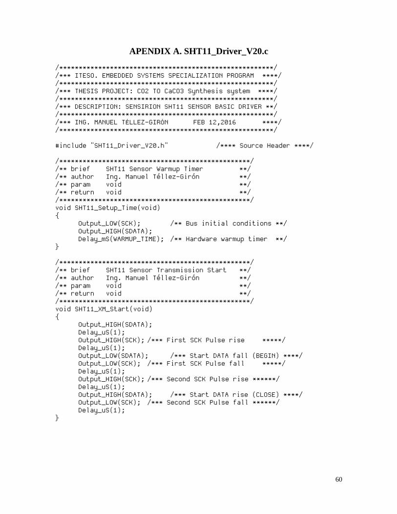
APENDIX A. SHT11_Driver_V20.c
/*******************************************************/ /*** ITESO. EMBEDDED SYSTEMS SPECIALIZATION PROGRAM ****/ /*******************************************************/ /*** THESIS PROJECT: CO2 TO CaCO3 Synthesis system ****/ /*******************************************************/ /*** DESCRIPTION: SENSIRION SHT11 SENSOR BASIC DRIVER **/ /*******************************************************/ /*** ING. MANUEL TÉLLEZ-GIRÓN FEB 12,2016 ****/ /*******************************************************/ #include "SHT11_Driver_V20.h" /**** Source Header ****/ /*************************************************/ /** brief SHT11 Sensor Warmup Timer **/ /** author Ing. Manuel Téllez-Girón **/ /** param void **/ /** return void **/ /*************************************************/ void SHT11_Setup_Time(void) { Output_LOW(SCK); /** Bus initial conditions **/ Output_HIGH(SDATA); Delay_mS(WARMUP_TIME); /** Hardware warmup timer **/ } /*************************************************/ /** brief SHT11 Sensor Transmission Start **/ /** author Ing. Manuel Téllez-Girón **/ /** param void **/ /** return void **/ /*************************************************/ void SHT11_XM_Start(void) { Output_HIGH(SDATA); Delay_uS(1); Output_HIGH(SCK); /*** First SCK Pulse rise *****/ Delay_uS(1); Output_LOW(SDATA); /*** Start DATA fall (BEGIN) ****/ Output_LOW(SCK); /*** First SCK Pulse fall *****/ Delay_uS(1); Output_HIGH(SCK); /*** Second SCK Pulse rise ******/ Delay_uS(1); Output_HIGH(SDATA); /*** Start DATA rise (CLOSE) ****/ Output_LOW(SCK); /*** Second SCK Pulse fall ******/ Delay_uS(1); }
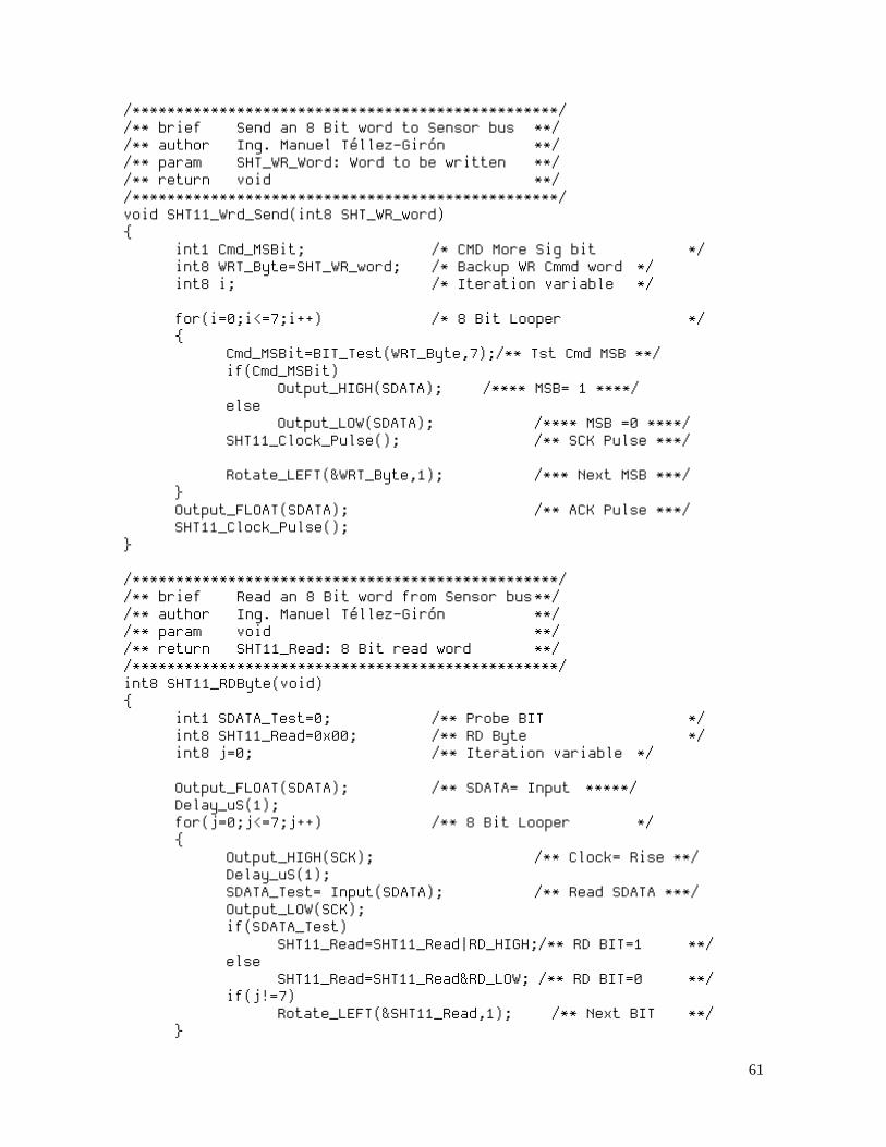
61
/*************************************************/ /** brief Send an 8 Bit word to Sensor bus **/ /** author Ing. Manuel Téllez-Girón **/ /** param SHT_WR_Word: Word to be written **/ /** return void **/ /*************************************************/ void SHT11_Wrd_Send(int8 SHT_WR_word) { int1 Cmd_MSBit; /* CMD More Sig bit */ int8 WRT_Byte=SHT_WR_word; /* Backup WR Cmmd word */ int8 i; /* Iteration variable */ for(i=0;i<=7;i++) /* 8 Bit Looper */ { Cmd_MSBit=BIT_Test(WRT_Byte,7);/** Tst Cmd MSB **/ if(Cmd_MSBit) Output_HIGH(SDATA); /**** MSB= 1 ****/ else Output_LOW(SDATA); /**** MSB =0 ****/ SHT11_Clock_Pulse(); /** SCK Pulse ***/ Rotate_LEFT(&WRT_Byte,1); /*** Next MSB ***/ } Output_FLOAT(SDATA); /** ACK Pulse ***/ SHT11_Clock_Pulse(); } /*************************************************/ /** brief Read an 8 Bit word from Sensor bus **/ /** author Ing. Manuel Téllez-Girón **/ /** param void **/ /** return SHT11_Read: 8 Bit read word **/ /*************************************************/ int8 SHT11_RDByte(void) { int1 SDATA_Test=0; /** Probe BIT */ int8 SHT11_Read=0x00; /** RD Byte */ int8 j=0; /** Iteration variable */ Output_FLOAT(SDATA); /** SDATA= Input *****/ Delay_uS(1); for(j=0;j<=7;j++) /** 8 Bit Looper */ { Output_HIGH(SCK); /** Clock= Rise **/ Delay_uS(1); SDATA_Test= Input(SDATA); /** Read SDATA ***/ Output_LOW(SCK); if(SDATA_Test) SHT11_Read=SHT11_Read|RD_HIGH;/** RD BIT=1 **/ else SHT11_Read=SHT11_Read&RD_LOW; /** RD BIT=0 **/ if(j!=7) Rotate_LEFT(&SHT11_Read,1); /** Next BIT **/ }

62
Output_LOW(SDATA); /** ACK Sequence */ Delay_uS(1); Output_HIGH(SCK); /** ACK Pulse **/ Delay_uS(2); Output_LOW(SCK); Delay_uS(1); Output_FLOAT(SDATA); /** Release SDATA */ return SHT11_Read; } /*************************************************/ /** brief Dummy checksum processor **/ /** author Ing. Manuel Téllez-Girón **/ /** param void **/ /** return void **/ /*************************************************/ void SHT11_Dummy_Chksm(void) { int8 k; Output_Float(SDATA); /** Release DATA */ for(k=0;k<=8;k++) SHT11_Clock_Pulse(); /** 9 Dummy SCKs */ } /** Include ACK **/ /*************************************************/ /** brief Issue a bus clock pulse in SCK line**/ /** author Ing. Manuel Téllez-Girón **/ /** param void **/ /** return void **/ /*************************************************/ void SHT11_Clock_Pulse(void) { Output_HIGH(SCK); /** Rise edge **/ Delay_uS(2); Output_LOW(SCK); /** Fall edge **/ Delay_uS(2); } /*************************************************/ /** brief Hold until SDATA line is released **/ /** author Ing. Manuel Téllez-Girón **/ /** param void **/ /** return void **/ /*************************************************/ void SHT11_Probe_SDATA_Free(void) { int1 Probe_SDATA=0; while(!Probe_SDATA) /** Test DATA Release **/ Probe_SDATA=Input(SDATA); }
63
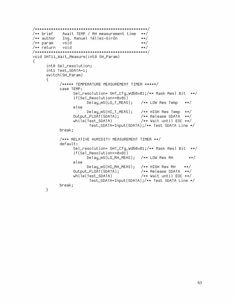
/*************************************************/ /** brief Await TEMP / RH measurement time **/ /** author Ing. Manuel Téllez-Girón **/ /** param void **/ /** return void **/ /*************************************************/ void SHT11_Wait_Measure(int8 SH_Param) { int8 Sel_resolution; int1 Test_SDATA=1; switch(SH_Param) { /***** TEMPERATURE MEASUREMENT TIMER *****/ case TEMP: Sel_resolution= SHT_Cfg_Wd&0x01;/** Mask Resl Bit **/ if(Sel_Resolution==0x01) Delay_mS(LO_T_MEAS); /** LOW Res Temp **/ else Delay_mS(HI_T_MEAS); /** HIGH Res Temp **/ Output_FLOAT(SDATA); /** Release SDATA **/ while(Test_SDATA) /** Wait until EOC **/ Test_SDATA=Input(SDATA);/** Test SDATA Line */ break; /*** RELATIVE HUMIDITY MEASUREMENT TIMER **/ default: Sel_resolution= SHT_Cfg_Wd&0x01;/** Mask Resl Bit **/ if(Sel_Resolution==0x01) Delay_mS(LO_RH_MEAS); /** LOW Res RH **/ else Delay_mS(HI_RH_MEAS); /** HIGH Res RH **/ Output_FLOAT(SDATA); /** Release SDATA **/ while(Test_SDATA) /** Wait until EOC **/ Test_SDATA=Input(SDATA);/** Test SDATA Line */ break; }
64
APENDIX B. SHT11_Driver_V20.h
/*******************************************************/ /*** ITESO. EMBEDDED SYSTEMS SPECIALIZATION PROGRAM ****/ /*******************************************************/ /*** THESIS PROJECT: CO2 TO CaCO3 Synthesis system ****/ /*******************************************************/ /*** DESCRIPTION: SENSIRION SHT11 SENSOR DRIVER HEADER */ /*******************************************************/ /*** ING. MANUEL TÉLLEZ-GIRÓN FEB 12,2016 ****/ /*******************************************************/ /********** HW INTERFACE PINOUT ASSIGNMENTS ******/ #define SCK PIN_B4 /* SERIAL CLOCK LINE */ #define SDATA PIN_B5 /* SERIAL DATA LINE */ /********** DRIVER CONSTANTS & MACROS ****************/ #define WARMUP_TIME 0x0C /** Sensor warmup time */ #define EDGE_TIME 0X01 /** Protocol pulse timer */ #define RD_LOW 0xFE /** Mask for & low **/ #define RD_HIGH 0x01 /** Mask for | high **/ #define LO_RH_MEAS 20 /** 8 Bit RH Meas time **/ #define LO_T_MEAS 80 /** 12 Bit T Meas Time **/ #define HI_RH_MEAS 80 /** 12 Bit RH Meas time **/ #define HI_T_MEAS 320 /** 14 Bit T Meas Time **/ /************** FUNCTIONS PROTOTYPES *****************/ void SHT11_Clock_Pulse(void); /** Issue SCK Pulse **/ void SHT11_XM_Start(void); void SHT11_Wrd_Send(int8 SHT_WR_word); void SHT11_Wait_Measure(int8 SH_Param); int8 SHT11_RDByte(void); void SHT11_Dummy_Chksm(void); void SHT11_Probe_SDATA_Free(void); void SHT11_Setup_Time(void);

65
APENDIX C. SPI_Driver_V20.c
/*******************************************************/ /*** ITESO. EMBEDDED SYSTEMS SPECIALIZATION PROGRAM ***/ /*******************************************************/ /*** THESIS PROJECT: CO2 TO CaCO3 Synthesis system ****/ /*******************************************************/ /*** DESCRIPTION: SSD1306 OLED-4 WIRE SPI BASIC DRIVER */ /*******************************************************/ /*** ING. MANUEL TÉLLEZ-GIRÓN FEB 12,2016 ***/ /*******************************************************/ #include "SPI_Driver_V20.h" /*************************************************/ /** brief SPI RESET Sequence **/ /** author Ing. Manuel Téllez-Girón **/ /** param void **/ /** return void **/ /*************************************************/ void SPI_Reset(void) { Output_LOW(SPI_RES); Delay_uS(50); Output_HIGH(SPI_RES); OLED_CTRL; SPI_CS_Enabled; SPI_Write(DISPLAY_OFF); /*** DISPLAY OFF ****/ SPI_CS_Disabled; } /*************************************************/ /** brief SPI OLED Initialization Sequence **/ /** author Ing. Manuel Téllez-Girón **/ /** param void **/ /** return void **/ /*************************************************/ void SPI_OLED_Init(void) { SPI_CS_Enabled; OLED_CTRL; SPI_Write(OLED_CLK_DIV); /** Clock Divider **/ SPI_Write(K_CLK_DIV); SPI_Write(OLED_MUX_RATIO);/* Multiplx Ratio **/ SPI_Write(K_MUX_RATIO); SPI_Write(OLED_DISP_OFST);/* Display Offset **/ SPI_Write(K_DISP_OFST);
66
SPI_Write(OLED_STRT_L0); /** Start Line 0 **/ SPI_Write(OLED_CH_PUMP); /** Charge Pump ON */ SPI_Write(K_CH_PUMP_ON); SPI_Write(OLED_ADRS_MOD); /* Addrs= Page Mode*/ SPI_Write(K_PAGE_MODE); SPI_Write(OLED_REMAP_ON);/*** Remap enabled **/ SPI_Write(COMSCN_NORMAL);/** COM Scan Normal**/ SPI_Write(OLED_COM_HW); /** COM HW Cfg= Alt**/ SPI_Write(K_ALTERNATE); SPI_Write(OLED_CONTRAST);/*** Contrast set ***/ SPI_Write(K_CONTRST_SET); SPI_Write(OLED_PRECHARG);/*** Prechrg Period**/ SPI_Write(K_PRECHRG_PER); SPI_Write(OLED_VCOM_DES);/*** VCOM Desel Level*/ SPI_Write(K_VCOM_DES_LV); SPI_Write(OLED_NINVERSE);/*** Inverse OFF ***/ SPI_Write(OLED_YESRAM); /*** Start with RAM***/ SPI_Write(DISPLAY_ON); /*** Display ON ***/ SPI_CS_Disabled; }
67
APENDIX D. SPI_Driver_V20.h
/*******************************************************/ /*** ITESO. EMBEDDED SYSTEMS SPECIALIZATION PROGRAM ****/ /*******************************************************/ /*** THESIS PROJECT: CO2 TO CaCO3 Synthesis system ****/ /*******************************************************/ /*** DESCRIPTION: SSD1306 OLED BASIC DRIVER HEADER **/ /*******************************************************/ /*** ING. MANUEL TÉLLEZ-GIRÓN FEB 12 2016 ****/ /*******************************************************/ /********** HW INTERFACE PINOUT ASSIGNMENTS ******/ #define SPI_SCLK PIN_C3 /* SPI Clock Line */ #define SPI_SDIN PIN_C5 /* SPI Data IN Line */ #define SPI_DC PIN_A5 /* DATA/CONTROL Line */ #define SPI_RES PIN_A4 /* RESET Signal */ #define SPI_CS PIN_A7 /* Chip Select Signal*/ #define OLED_CTRL Output_LOW(SPI_DC) #define OLED_DATA Output_HIGH(SPI_DC) #define SPI_CS_Enabled Output_LOW(SPI_CS) #define SPI_CS_Disabled Output_HIGH(SPI_CS) /********** OLED DRIVER CONFIG DEFINITIONS *******/ /**** Clock divider *****/ #define OLED_CLK_DIV 0xD5 #define K_CLK_DIV 0x80 /**** Multiplex ratio***/ #define OLED_MUX_RATIO 0xA8 #define K_MUX_RATIO 0x3F /**** Display Offset ***/ #define OLED_DISP_OFST 0xD3 #define K_DISP_OFST 0x00 /**** Start Line ******/ #define OLED_STRT_L0 0x40 /**** Charge Pump ******/ #define OLED_CH_PUMP 0x8D #define K_CH_PUMP_ON 0x14 /**** Address Mode ******/ #define OLED_ADRS_MOD 0x20 #define K_PAGE_MODE 0x02
68
/**** Remap mode ********/ #define OLED_REMAP_ON 0xA1 /**** COM Scan dir ******/ #define COMSCN_NORMAL 0xC0 /**** COM HW CONFIG *****/ #define OLED_COM_HW 0xDA #define K_ALTERNATE 0x12 /**** CONTRAST SETTING **/ #define OLED_CONTRAST 0x81 #define K_CONTRST_SET 0xB0 /**** PRECHARGE PERIOD **/ #define OLED_PRECHARG 0xD9 #define K_PRECHRG_PER 0xF1 /**** VCOM DESELECT LEV */ #define OLED_VCOM_DES 0xDB #define K_VCOM_DES_LV 0x20 /**** INVERSE MODE ******/ #define OLED_NINVERSE 0xA6 /**** RAM AT STARTUP ****/ #define OLED_YESRAM 0xA4 /** OLED POWER CONTROL **/ #define DISPLAY_ON 0xAF #define DISPLAY_OFF 0xAE /********** DRIVER CONSTANTS DEFINITION **********/ #define DSP_OFF 0xAF /* Display Reset CMD */ #define CTRL 0x00 /* Control command **/ #define DAT 0x01 /* Data Disp command */ #define Tsetup 0x05 /* Data setup uS time*/ #define Tclk 0x05 /* Tclock **/ #define RSTTMR 0x20 /* uS SPI RESET Time */ /************* FUNCTIONS PROTOTYPES **************/ void SPI_Reset(void); /* OLED SPI Modl Rst */ void SPI_OLED_Init(void); /* OLED Initialize **/
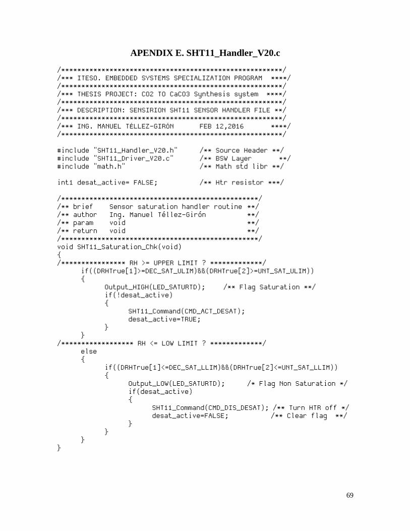
69
APENDIX E. SHT11_Handler_V20.c
/*******************************************************/ /*** ITESO. EMBEDDED SYSTEMS SPECIALIZATION PROGRAM ****/ /*******************************************************/ /*** THESIS PROJECT: CO2 TO CaCO3 Synthesis system ****/ /*******************************************************/ /*** DESCRIPTION: SENSIRION SHT11 SENSOR HANDLER FILE **/ /*******************************************************/ /*** ING. MANUEL TÉLLEZ-GIRÓN FEB 12,2016 ****/ /*******************************************************/ #include "SHT11_Handler_V20.h" /** Source Header **/ #include "SHT11_Driver_V20.c" /** BSW Layer **/ #include "math.h" /** Math std libr **/ int1 desat_active= FALSE; /** Htr resistor ***/ /*************************************************/ /** brief Sensor saturation handler routine **/ /** author Ing. Manuel Téllez-Girón **/ /** param void **/ /** return void **/ /*************************************************/ void SHT11_Saturation_Chk(void) { /**************** RH >= UPPER LIMIT ? *************/ if((DRHTrue[1]>=DEC_SAT_ULIM)&&(DRHTrue[2]>=UNT_SAT_ULIM)) { Output_HIGH(LED_SATURTD); /** Flag Saturation **/ if(!desat_active) { SHT11_Command(CMD_ACT_DESAT); desat_active=TRUE; } } /****************** RH <= LOW LIMIT ? *************/ else { if((DRHTrue[1]<=DEC_SAT_LLIM)&&(DRHTrue[2]<=UNT_SAT_LLIM)) { Output_LOW(LED_SATURTD); /* Flag Non Saturation */ if(desat_active) { SHT11_Command(CMD_DIS_DESAT); /** Turn HTR off */ desat_active=FALSE; /** Clear flag **/ } } } }
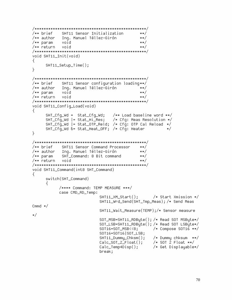
70
/*************************************************/ /** brief SHT11 Sensor Initialization **/ /** author Ing. Manuel Téllez-Girón **/ /** param void **/ /** return void **/ /*************************************************/ void SHT11_Init(void) { SHT11_Setup_Time(); } /*************************************************/ /** brief SHT11 Sensor configuration loading **/ /** author Ing. Manuel Téllez-Girón **/ /** param void **/ /** return void **/ /*************************************************/ void SHT11_Config_Load(void) { SHT_Cfg_Wd = Stat_Cfg_Wd; /** Load baseline word **/ SHT_Cfg_Wd |= Stat_Hi_Res; /* Cfg: Meas Resolution */ SHT_Cfg_Wd |= Stat_OTP_Reld; /* Cfg: OTP Cal Reload */ SHT_Cfg_Wd &= Stat_Heat_OFF; /* Cfg: Heater */ } /*************************************************/ /** brief SHT11 Sensor Command Processor **/ /** author Ing. Manuel Téllez-Girón **/ /** param SHT_Command: 8 Bit command **/ /** return void **/ /*************************************************/ void SHT11_Command(int8 SHT_Command) { switch(SHT_Command) { /**** Command: TEMP MEASURE ***/ case CMD_RD_Temp: SHT11_XM_Start(); /* Start Xmission */ SHT11_Wrd_Send(SHT_Tmp_Meas); /* Send Meas Cmmd */ SHT11_Wait_Measure(TEMP);/* Sensor measure */ SOT_MSB=SHT11_RDByte(); /* Read SOT MSByte*/ SOT_LSB=SHT11_RDByte(); /* Read SOT LSByte*/ SOT16=SOT_MSB<<8; /* Compose SOT16 **/ SOT16=SOT16|SOT_LSB; SHT11_Dummy_Chksm(); /* Dummy chksum **/ Calc_SOT_2_Float(); /* SOT 2 Float **/ Calc_Temp4Disp(); /* Get Displayable*/ break;

71
/**** Command: RH% MEASURE ****/ case CMD_RD_RH: SHT11_XM_Start(); /* Start Xmission */ SHT11_Wrd_Send(SHT_RH_Meas); /* Send Meas Cmmd */ SHT11_Wait_Measure(RH); /* Sensor measure */ SORH_MSB=SHT11_RDByte();/* RD SORH MSByte */ SORH_LSB=SHT11_RDByte();/* RD SORH LSByte */ SORH16= SORH_MSB<<8; /* Compose SORH16 */ SORH16= SORH16|SORH_LSB; SHT11_Dummy_Chksm(); /* Dummy chksum */ Calc_SORH_2_Float(); /* SORH 2 Float **/ Calc_RH4Disp(); /* Get Displayable*/ break; /**** Command: WRITE STATUS ***/ case CMD_WR_Status: SHT11_XM_Start(); /* Start Xmission */ SHT11_Config_Load();/* Ld config params */ SHT11_Wrd_Send(SHT_WR_Stat);/* Write STATUS Cmd */ SHT11_Wrd_Send(SHT_Cfg_Wd);/* Write CFG word */ break; /**** Command: READ STATUS ****/ case CMD_RD_Status: SHT11_XM_Start(); /* Start Xmission */ SHT11_Wrd_Send(SHT_RD_Stat);/* Read STATUS Cmd */ RD_Status=SHT11_RDByte();/* Execute STATUS RD*/ SHT11_Dummy_Chksm();/* Bypass Checksum */ break; /**** Command: ACTIV DESAT ***/ case CMD_ACT_DESAT: SHT11_XM_Start(); /* Start Xmission */ SHT_Cfg_Wd |=Stat_Heat_ON; /** Enable Heater ***/ SHT11_Wrd_Send(SHT_WR_Stat);/* Write STATUS Cmd */ SHT11_Wrd_Send(SHT_Cfg_Wd); /* Write CFG word */ break;
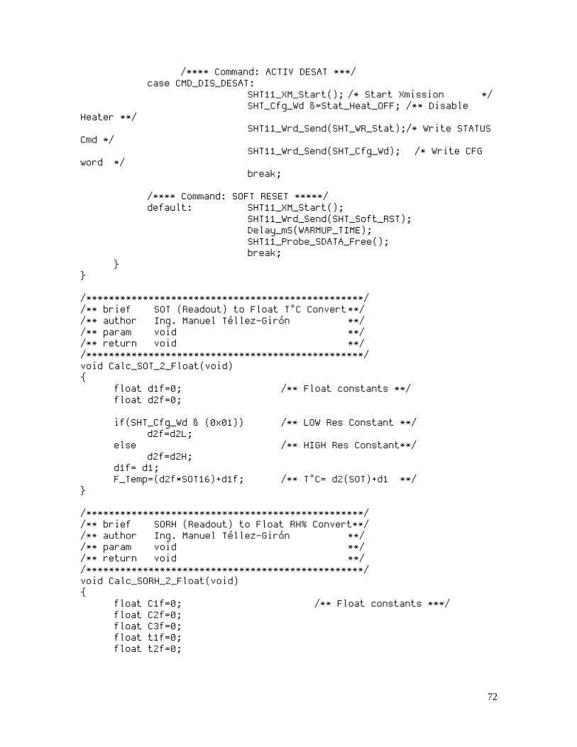
72
/**** Command: ACTIV DESAT ***/ case CMD_DIS_DESAT: SHT11_XM_Start(); /* Start Xmission */ SHT_Cfg_Wd &=Stat_Heat_OFF; /** Disable Heater **/ SHT11_Wrd_Send(SHT_WR_Stat);/* Write STATUS Cmd */ SHT11_Wrd_Send(SHT_Cfg_Wd); /* Write CFG word */ break; /**** Command: SOFT RESET *****/ default: SHT11_XM_Start(); SHT11_Wrd_Send(SHT_Soft_RST); Delay_mS(WARMUP_TIME); SHT11_Probe_SDATA_Free(); break; } } /*************************************************/ /** brief SOT (Readout) to Float T°C Convert **/ /** author Ing. Manuel Téllez-Girón **/ /** param void **/ /** return void **/ /*************************************************/ void Calc_SOT_2_Float(void) { float d1f=0; /** Float constants **/ float d2f=0; if(SHT_Cfg_Wd & (0x01)) /** LOW Res Constant **/ d2f=d2L; else /** HIGH Res Constant**/ d2f=d2H; d1f= d1; F_Temp=(d2f*SOT16)+d1f; /** T°C= d2(SOT)+d1 **/ } /*************************************************/ /** brief SORH (Readout) to Float RH% Convert**/ /** author Ing. Manuel Téllez-Girón **/ /** param void **/ /** return void **/ /*************************************************/ void Calc_SORH_2_Float(void) { float C1f=0; /** Float constants ***/ float C2f=0; float C3f=0; float t1f=0; float t2f=0;
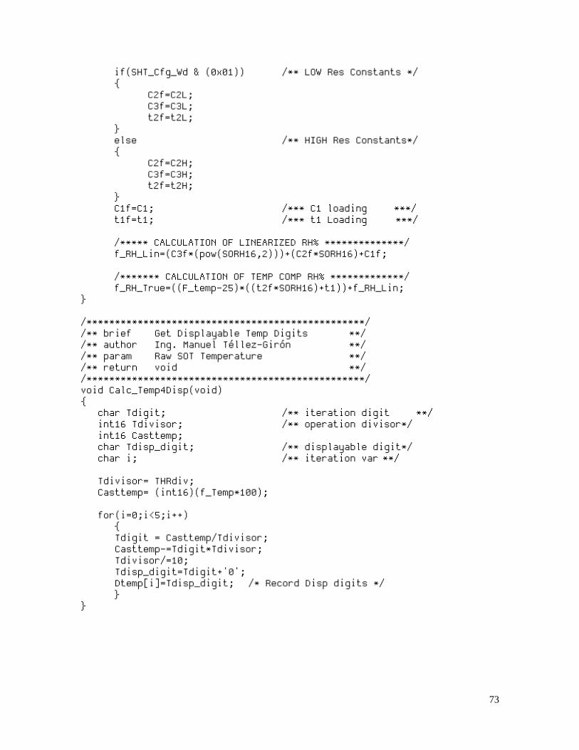
73
if(SHT_Cfg_Wd & (0x01)) /** LOW Res Constants */ { C2f=C2L; C3f=C3L; t2f=t2L; } else /** HIGH Res Constants*/ { C2f=C2H; C3f=C3H; t2f=t2H; } C1f=C1; /*** C1 loading ***/ t1f=t1; /*** t1 Loading ***/ /***** CALCULATION OF LINEARIZED RH% **************/ f_RH_Lin=(C3f*(pow(SORH16,2)))+(C2f*SORH16)+C1f; /******* CALCULATION OF TEMP COMP RH% *************/ f_RH_True=((F_temp-25)*((t2f*SORH16)+t1))+f_RH_Lin; } /*************************************************/ /** brief Get Displayable Temp Digits **/ /** author Ing. Manuel Téllez-Girón **/ /** param Raw SOT Temperature **/ /** return void **/ /*************************************************/ void Calc_Temp4Disp(void) { char Tdigit; /** iteration digit **/ int16 Tdivisor; /** operation divisor*/ int16 Casttemp; char Tdisp_digit; /** displayable digit*/ char i; /** iteration var **/ Tdivisor= THRdiv; Casttemp= (int16)(f_Temp*100); for(i=0;i<5;i++) { Tdigit = Casttemp/Tdivisor; Casttemp-=Tdigit*Tdivisor; Tdivisor/=10; Tdisp_digit=Tdigit+'0'; Dtemp[i]=Tdisp_digit; /* Record Disp digits */ } }
74
/*************************************************/ /** brief Get Displayable RH Digits **/ /** author Ing. Manuel Téllez-Girón **/ /** param void **/ /** return void **/ /*************************************************/ void Calc_RH4Disp(void) { int16 RHdivisor; /** operation divisor*/ int16 CastRH; /** Cast RH variable */ char RHdigit; /** iteration digit **/ char RHdisp_digit; /** displayable digit*/ char i; /** iteration var **/ /************ Linearized RH Calculation *****/ RHdivisor= RHdiv; CastRH=(int16)(f_RH_Lin*100); for(i=0;i<5;i++) { RHdigit = CastRH/RHdivisor; CastRH-= RHdigit*RHdivisor; RHdivisor/=10; RHdisp_digit=RHdigit+'0'; DRHLin[i]=RHdisp_digit;/* Record Disp digits */ } /************* True RH Calculation *********/ RHDivisor= RHDiv; CastRH= (int16)(f_RH_True*100); for(i=0;i<5;i++) { RHdigit = CastRH/RHdivisor; CastRH-= RHdigit*RHdivisor; RHdivisor/=10; RHdisp_digit=RHdigit+'0'; DRHTrue[i]=RHdisp_digit;/* Record Disp digits */ } }
75
/*************************************************/ /** brief Calculate DP from Temp & RH% **/ /** author Ing. Manuel Téllez-Girón **/ /** param void **/ /** return void **/ /*************************************************/ void Calc_DewPoint(void) { float logfactor; float tempfactor; logfactor= log(f_RH_TruE/100); tempfactor= (m*(f_Temp))/(Tn+f_Temp); f_Dewpoint= Tn*(tempfactor+logfactor); f_Dewpoint= f_Dewpoint/(m-logfactor-tempfactor); } /*************************************************/ /** brief Get Displayable Dew Point **/ /** author Ing. Manuel Téllez-Girón **/ /** param void **/ /** return void **/ /*************************************************/ void Calc_DP4Disp(void) { signed int16 DPcast; /* ftoa variable*/ int16 DPdivisor; int1 DPsign=0; /** Sign flag **/ char i; char DPdisp_digit; char DPdigit; DPcast=(signed int16)(f_Dewpoint*100); if((DPcast & DPcastmask)== DPcastmask)/* Negative? */ { DPcast=1-DPcast; DPsign=1; } DPdivisor=DPdiv; for(i=0;i<5;i++) { DPdigit = DPcast/DPdivisor; DPcast-= DPdigit*DPdivisor; DPdivisor/=10; DPdisp_digit=DPdigit+'0'; DDewPt[i]=DPdisp_digit; /* Record Disp digits */ } }
76
APENDIX F. SHT11_Handler_V20.h
/*******************************************************/ /*** ITESO. EMBEDDED SYSTEMS SPECIALIZATION PROGRAM ***/ /*******************************************************/ /*** THESIS PROJECT: CO2 TO CaCO3 Synthesis system ****/ /*******************************************************/ /*** DESCRIPTION: SENSIRION SHT11 SENSOR HANDLER HEADER*/ /*******************************************************/ /*** ING. MANUEL TÉLLEZ-GIRÓN JAN 14,2016 ***/ /*******************************************************/ /************ GLOBAL VARIABLES DEFINITION ************/ int8 SOT_MSB; /** Readout Temp MSB */ int8 SOT_LSB; /** Readout Temp LSB */ int8 SORH_MSB; /** Readout RH MSB **/ int8 SORH_LSB; /** Readout RH LSB **/ int16 SOT16= 0x0000; /** Whole SOT RD **/ int16 SORH16=0x0000; /** Whole SORH RD **/ int8 RD_Status; /** Read STATUS reg **/ int8 SHT_Cfg_Wd; /** Composed cfg wrd */ float f_Temp; /** Float pt Temp **/ float f_RH_Lin; /** Float Linear RH% */ float f_RH_True; /** Float True RH%*/ float f_Dewpoint; /** Float Dew Point **/ char DTemp[5]; /** Displ Temp Chrs */ char DRHLin[5]; /** Displ RH Lin Ch */ char DRHTrue[5]; /** Disp Comp RH Chrs*/ char DDewPt[5]; /** Displayable DewPt*/ /********* PARAMETERS CONVERSION CONSTANTS ***********/ float const d1 = -39.65; /** Temp Offset **/ float const d2H = 0.01; /** High Res T Coeff**/ float const d2L = 0.04; /** Low Res T Coeff **/ float const C1 = -2.0468; /** Const RH Offset **/ float const C2H = 0.0367; /** 1st Deg RH HR C **/ float const C2L = 0.5872; /** 1st Deg RH LR C **/ float const C3H = -1.5995E-6; /** 2nd Deg RH HRC **/ float const C3L = -4.085E-4; /** 2nd Deg RH Lo RC */ float const t1 = 0.01; /** Comp RH factor 1 */ float const t2L = 0.00128; /** Comp RH factor 2**/ float const t2H = 0.00008; /** Comp RH factor 2**/ float const m = 17.62; /** Dew point m fact */ float const Tn = 243.12; /** Dew point Tn fact*/
77
/************* CONVERSION MACROS CONSTANTS **********/ int16 const THRdiv = 10000; /** Temp HRres divr **/ int16 const RHdiv = 10000; /** RH divisor **/ int16 const DPdiv = 10000; /** DP divisor */ int16 const DPcastmask = 0x8000; /** DP ftoa mask */ /**************** SHT11 COMMAND LIST *****************/ #define CMD_RD_Temp 0x01 /* Temp measurement **/ #define CMD_RD_RH 0x02 /* RH Measurement **/ #define CMD_WR_Status 0x03 /* Write Status reg **/ #define CMD_RD_Status 0x04 /* Read Status reg **/ #define CMD_Soft_RST 0x05 /* Soft RST Command **/ #define CMD_ACT_DESAT 0x06 /* Enable Desaturat **/ #define CMD_DIS_DESAT 0x07 /* Disable Desaturt **/ /*********** SHT11 COMMAND WORDS MACROS **************/ #define SHT_Tmp_Meas 0b00000011 /* Measure Temp **/ #define SHT_RH_Meas 0b00000101 /* Measure RH% **/ #define SHT_WR_Stat 0b00000110 /* RD Status Reg **/ #define SHT_RD_Stat 0b00000111 /* WR Status Reg **/ #define SHT_Soft_RST 0b00011110 /* Soft Reset **/ /******** SHT11 SATURATION LIMITS SETTINGS **********/ #define DEC_SAT_ULIM 0x38 /*RH Decs UTL **/ #define UNT_SAT_ULIM 0x35 /*RH Units UTL **/ #define DEC_SAT_LLIM 0x35 /*RH Decs LTL **/ #define UNT_SAT_LLIM 0x39 /*RH Units LTL **/ /********* SHT11 CONFIG PARAMETERS MACROS ***********/ #define Stat_Cfg_Wd 0b00000000 /* Stat Baseline */ #define Stat_Hi_Res 0b00000000 /* Hi Res Mask */ #define Stat_Low_Res 0b00000001 /* Low Res Mask */ #define Stat_OTP_Reld 0b00000000 /* Calib Reload */ #define Stat_OTP_NoReld 0b00000010 /* No Reload */ #define Stat_Heat_ON 0b00000100 /* Heatr ON Mask */ #define Stat_Heat_OFF 0b11111011 /* Heatr OFF Mask*/ /********* MEASUREMENT PARAMETERS FLAGS **************/ #define TEMP 0x01 /* TEMP Meas flag*/ #define RH 0x02 /* RH% Meas flag */
78
/*****************************************************/ /************** FUNCTIONS PROTOTYPES *****************/ /*****************************************************/ /****** SENSOR COMMANDS PROCESSOR *******************/ void SHT11_Command(int8 SHT_Command); /****** CONVERT TEMP HEX READOUT TO FLOATING POINT ***/ void Calc_SOT_2_Float(void); /****** CONVERT RH% HEX READUT TO FLOATING POINT *****/ void Calc_SORH_2_Float(void); /****** CREATE TEMP DISPLAYABLE INT DIGITS ***********/ void Calc_Temp4Disp(void); /****** CREATE RH% DISPLAYABLE INT DIGITS ************/ void Calc_RH4Disp(void); /************** CALCULATE DEW POINT *****************/ void Calc_DewPoint(void); /**** CREATE DEW POINT DISPLAYABLE INT DIGITS ********/ void Calc_DP4Disp(void);
79
APENDIX G. OLED_Handler_V20.c
/*******************************************************/ /*** ITESO. EMBEDDED SYSTEMS SPECIALIZATION PROGRAM ***/ /*******************************************************/ /*** THESIS PROJECT: CO2 TO CaCO3 Synthesis system ****/ /*******************************************************/ /*** DESCRIPTION: SSD1306 OLED HANDLER FILE **/ /*******************************************************/ /*** ING. MANUEL TÉLLEZ-GIRÓN FEB 12,2016 ***/ /*******************************************************/ #include "OLED_Chartable_V20.h" #include "OLED_Handler_V20.h" #include "SPI_Driver_V20.c" char OLEDtext[5]; /** OLED Char buffer **/ /*************************************************/ /** brief OLED Saturation signals update **/ /** author Ing. Manuel Téllez-Girón **/ /** param void **/ /** return void **/ /*************************************************/ void OLED_Satur_Upd(void) { OLED_Setcursor(ROW6_PAGE,HT_ICON_COL); if(desat_active) { OLED_Chardisp(0x00); /* active Icon **/ Output_HIGH(LED_HEATER); } else { OLED_Chardisp(0x01); /* inactive Icon*/ Output_LOW(LED_HEATER); } OLED_sat_status(); /* Update text **/ } /*************************************************/ /** brief OLED Forced heat display **/ /** author Ing. Manuel Téllez-Girón **/ /** param void **/ /** return void **/ /*************************************************/
80
void OLED_forced_heat(void) { OLED_Setcursor(ROW5_PAGE,SAT_TXT_COL); OLED_Chardisp('F'); OLED_Chardisp('O'); OLED_Chardisp('R'); OLED_Chardisp('C'); OLED_Chardisp('E'); OLED_Chardisp('D'); OLED_Chardisp(' '); OLED_Chardisp('H'); OLED_Chardisp('T'); } /*************************************************/ /** brief OLED Saturation Text updating **/ /** author Ing. Manuel Téllez-Girón **/ /** param void **/ /** return void **/ /*************************************************/ void OLED_sat_status(void) { OLED_Setcursor(ROW5_PAGE,SAT_TXT_COL); if(desat_active) { OLED_Chardisp('S'); OLED_Chardisp('A'); OLED_Chardisp('T'); OLED_Chardisp('U'); OLED_Chardisp('R'); OLED_Chardisp('A'); OLED_Chardisp('T'); OLED_Chardisp('E'); OLED_Chardisp('D'); } else { OLED_Chardisp('N'); OLED_Chardisp('O'); OLED_Chardisp('N'); OLED_Chardisp(' '); OLED_Chardisp('S'); OLED_Chardisp('A'); OLED_Chardisp('T'); OLED_Chardisp(' '); OLED_Chardisp(' '); } }
81
/*************************************************/ /** brief OLED Splash screen display **/ /** author Ing. Manuel Téllez-Girón **/ /** param void **/ /** return void **/ /*************************************************/ void OLED_Splashscr(void) { Skeletonscr_Row1(); /** First Skeleton row **/ Skeletonscr_Row2(); /** Second Skeleton row**/ Skeletonscr_Row3(); /** Third Skeleton row **/ Skeletonscr_Row4(); /** Fourth Skeleton row**/ Skeletonscr_Row5(); /** Fifth Skeleton row **/ Skeletonscr_Row6(); /** Sixth Skeleton row **/ } /*************************************************/ /** brief OLED Skeleton Display 1st row **/ /** author Ing. Manuel Téllez-Girón **/ /** param void **/ /** return void **/ /*************************************************/ void Skeletonscr_Row1(void) { OLED_Setcursor(ROW1_PAGE,ROW1_COL); /* First row */ OLED_Chardisp('*'); OLED_Chardisp(' '); OLED_Chardisp('C'); OLED_Chardisp('O'); OLED_Chardisp('2'); OLED_Chardisp(' '); OLED_Chardisp('S'); OLED_Chardisp('Y'); OLED_Chardisp('N'); OLED_Chardisp('T'); OLED_Chardisp('H'); OLED_Chardisp(' '); OLED_Chardisp('S'); OLED_Chardisp('Y'); OLED_Chardisp('S'); OLED_Chardisp('T'); OLED_Chardisp('E'); OLED_Chardisp('M'); OLED_Chardisp(' '); OLED_Chardisp('V'); OLED_Chardisp('1'); OLED_Chardisp('.'); OLED_Chardisp('0'); OLED_Chardisp(' '); OLED_Chardisp('*'); }

82
/*************************************************/ /** brief OLED Skeleton Display 2nd row **/ /** author Ing. Manuel Téllez-Girón **/ /** param void **/ /** return void **/ /*************************************************/ void Skeletonscr_Row2(void) { char i; OLED_Setcursor(ROW2_PAGE,ROW2_COL);/* Second Row */ for(i=0;i<=25;i++) { OLED_Chardisp('*'); } } /*************************************************/ /** brief OLED Skeleton Display 3rd row **/ /** author Ing. Manuel Téllez-Girón **/ /** param void **/ /** return void **/ /*************************************************/ void Skeletonscr_Row3(void) { OLED_Setcursor(ROW3_PAGE,ROW3_COL); /* Third Row */ OLED_Chardisp('*'); OLED_Chardisp('*'); OLED_Chardisp(' '); OLED_Chardisp('M'); OLED_Chardisp('T'); OLED_Chardisp('G'); OLED_Chardisp('E'); OLED_Chardisp('.'); OLED_Chardisp('I'); OLED_Chardisp('T'); OLED_Chardisp('E'); OLED_Chardisp('S'); OLED_Chardisp('O'); OLED_Chardisp(' '); OLED_Chardisp('E'); OLED_Chardisp('S'); OLED_Chardisp('E'); OLED_Chardisp('.'); OLED_Chardisp('2'); OLED_Chardisp('0'); OLED_Chardisp('1'); OLED_Chardisp('6'); OLED_Chardisp(' '); OLED_Chardisp('*'); OLED_Chardisp('*'); }
83
/*************************************************/ /** brief OLED Skeleton Display 4th row **/ /** author Ing. Manuel Téllez-Girón **/ /** param void **/ /** return void **/ /*************************************************/ void Skeletonscr_Row4(void) { OLED_Setcursor(ROW4_PAGE,ROW4_COL); /* Fourth Row */ OLED_Chardisp('T'); /* Temp messg */ OLED_Chardisp('e'); OLED_Chardisp('m'); OLED_Chardisp('p'); OLED_Chardisp(' '); OLED_Chardisp('0'); OLED_Chardisp('0'); OLED_Chardisp('0'); OLED_Chardisp('.'); OLED_Chardisp('0'); OLED_Chardisp('0'); OLED_Chardisp('°'); OLED_Chardisp('C'); OLED_Chardisp(' '); OLED_Chardisp(' '); OLED_Chardisp('R'); /* RH Message */ OLED_Chardisp('H'); OLED_Chardisp(' '); OLED_Chardisp('0'); OLED_Chardisp('0'); OLED_Chardisp('.'); OLED_Chardisp('0'); OLED_Chardisp('0'); OLED_Chardisp(' '); OLED_Chardisp('%'); } /*************************************************/ /** brief OLED Skeleton Display 5th row **/ /** author Ing. Manuel Téllez-Girón **/ /** param void **/ /** return void **/ /*************************************************/ void Skeletonscr_Row5(void) { OLED_Setcursor(ROW5_PAGE,ROW5_COL); /* Fifth Row */ OLED_Chardisp('D'); /* Dew Pt msg*/ OLED_Chardisp('E'); OLED_Chardisp('W'); OLED_Chardisp(' '); OLED_Chardisp('P'); OLED_Chardisp('t'); OLED_Chardisp(' '); OLED_Chardisp('0'); OLED_Chardisp('0');

84
OLED_Chardisp('.'); OLED_Chardisp('0'); OLED_Chardisp('0'); OLED_Chardisp('°'); OLED_Chardisp('C');; OLED_Chardisp(' '); OLED_Chardisp('N'); OLED_Chardisp('O'); OLED_Chardisp('N'); OLED_Chardisp(' '); OLED_Chardisp('S'); OLED_Chardisp('A'); OLED_Chardisp('T'); } /*************************************************/ /** brief OLED Skeleton Display 6th row **/ /** author Ing. Manuel Téllez-Girón **/ /** param void **/ /** return void **/ /*************************************************/ void Skeletonscr_Row6(void) { OLED_Setcursor(ROW6_PAGE,ROW6_COL);/* Sixth Row */ OLED_Chardisp('g'); /* Gas intake*/ OLED_Chardisp('i'); OLED_Chardisp(' '); OLED_Chardisp(0x00); /** Active **/ OLED_Chardisp(' '); OLED_Chardisp(' '); OLED_Chardisp('c'); /* Cold source*/ OLED_Chardisp('o'); OLED_Chardisp('o'); OLED_Chardisp('l'); OLED_Chardisp(' '); OLED_Chardisp(0x01); /**Inactive **/ OLED_Chardisp(' '); OLED_Chardisp(' '); OLED_Chardisp('h'); /* Desat heater*/ OLED_Chardisp('t'); OLED_Chardisp('r'); OLED_Chardisp(' '); OLED_Chardisp(0x01); /** Inactive **/ } /*************************************************/ /** brief OLED Temperature refresh routine **/ /** author Ing. Manuel Téllez-Girón **/ /** param void **/ /** return void **/ /*************************************************/
85
void OLED_Temp_Upd(void) { OLED_Setcursor(ROW4_PAGE,T_COL_HUND); ASC_2_OLED(DTemp[0]); OLED_Writechar(OLEDtext); OLED_Setcursor(ROW4_PAGE,T_COL_DECS); ASC_2_OLED(DTemp[1]); OLED_Writechar(OLEDtext); OLED_Setcursor(ROW4_PAGE,T_COL_UNITS); ASC_2_OLED(DTemp[2]); OLED_Writechar(OLEDtext); OLED_Setcursor(ROW4_PAGE,T_COL_TENTH); ASC_2_OLED(DTemp[3]); OLED_Writechar(OLEDtext); OLED_Setcursor(ROW4_PAGE,T_COL_CENTS); ASC_2_OLED(DTemp[4]); OLED_Writechar(OLEDtext); } /*************************************************/ /** brief OLED RH refresh routine **/ /** author Ing. Manuel Téllez-Girón **/ /** param void **/ /** return void **/ /*************************************************/ void OLED_RH_Upd(void) { OLED_Setcursor(ROW4_PAGE,H_COL_DECS); ASC_2_OLED(DRHTrue[1]); OLED_Writechar(OLEDtext); OLED_Setcursor(ROW4_PAGE,H_COL_UNITS); ASC_2_OLED(DRHTrue[2]); OLED_Writechar(OLEDtext); OLED_Setcursor(ROW4_PAGE,H_COL_TENTH); ASC_2_OLED(DRHTrue[3]); OLED_Writechar(OLEDtext); OLED_Setcursor(ROW4_PAGE,H_COL_CENTS); ASC_2_OLED(DRHTrue[4]); OLED_Writechar(OLEDtext); } /*************************************************/ /** brief OLED Dew Point refresh routine **/ /** author Ing. Manuel Téllez-Girón **/ /** param void **/ /** return void **/ /*************************************************/
86
void OLED_DP_Upd(void) { OLED_Setcursor(ROW5_PAGE,W_COL_DECS); ASC_2_OLED(DDewPt[1]); OLED_Writechar(OLEDtext); OLED_Setcursor(ROW5_PAGE,W_COL_UNITS); ASC_2_OLED(DDewPt[2]); OLED_Writechar(OLEDtext); OLED_Setcursor(ROW5_PAGE,W_COL_TENTH); ASC_2_OLED(DDewPt[3]); OLED_Writechar(OLEDtext); OLED_Setcursor(ROW5_PAGE,W_COL_CENTS); ASC_2_OLED(DDewPt[4]); OLED_Writechar(OLEDtext); } /*************************************************/ /** brief OLED Display a single character **/ /** author Ing. Manuel Téllez-Girón **/ /** param ASCII Character **/ /** return none **/ /*************************************************/ void OLED_Chardisp(char ASCchar) { ASC_2_OLED(ASCchar); OLED_Writechar(OLEDtext); } /*************************************************/ /** brief ASCII Number to OLED Char convert **/ /** author Ing. Manuel Téllez-Girón **/ /** param ASCII Byte **/ /** return OLED graphic char in OLEDtext var **/ /*************************************************/ void ASC_2_OLED(char ASCparam) { switch(ASCparam) { case '0': OLEDtext[0]=ch_ZERO[0]; OLEDtext[1]=ch_ZERO[1]; OLEDtext[2]=ch_ZERO[2]; OLEDtext[3]=ch_ZERO[3]; OLEDtext[4]=ch_ZERO[4]; break; case '1': OLEDtext[0]=ch_ONE[0]; OLEDtext[1]=ch_ONE[1]; OLEDtext[2]=ch_ONE[2]; OLEDtext[3]=ch_ONE[3]; OLEDtext[4]=ch_ONE[4]; break;

87
case '2': OLEDtext[0]=ch_TWO[0]; OLEDtext[1]=ch_TWO[1]; OLEDtext[2]=ch_TWO[2]; OLEDtext[3]=ch_TWO[3]; OLEDtext[4]=ch_TWO[4]; break; case '3': OLEDtext[0]=ch_THREE[0]; OLEDtext[1]=ch_THREE[1]; OLEDtext[2]=ch_THREE[2]; OLEDtext[3]=ch_THREE[3]; OLEDtext[4]=ch_THREE[4]; break; case '4': OLEDtext[0]=ch_FOUR[0]; OLEDtext[1]=ch_FOUR[1]; OLEDtext[2]=ch_FOUR[2]; OLEDtext[3]=ch_FOUR[3]; OLEDtext[4]=ch_FOUR[4]; break; case '5': OLEDtext[0]=ch_FIVE[0]; OLEDtext[1]=ch_FIVE[1]; OLEDtext[2]=ch_FIVE[2]; OLEDtext[3]=ch_FIVE[3]; OLEDtext[4]=ch_FIVE[4]; break; case '6': OLEDtext[0]=ch_SIX[0]; OLEDtext[1]=ch_SIX[1]; OLEDtext[2]=ch_SIX[2]; OLEDtext[3]=ch_SIX[3]; OLEDtext[4]=ch_SIX[4]; break; case '7': OLEDtext[0]=ch_SEVEN[0]; OLEDtext[1]=ch_SEVEN[1]; OLEDtext[2]=ch_SEVEN[2]; OLEDtext[3]=ch_SEVEN[3]; OLEDtext[4]=ch_SEVEN[4]; break; case '8': OLEDtext[0]=ch_EIGHT[0]; OLEDtext[1]=ch_EIGHT[1]; OLEDtext[2]=ch_EIGHT[2]; OLEDtext[3]=ch_EIGHT[3]; OLEDtext[4]=ch_EIGHT[4]; break; case '9': OLEDtext[0]=ch_NINE[0]; OLEDtext[1]=ch_NINE[1]; OLEDtext[2]=ch_NINE[2]; OLEDtext[3]=ch_NINE[3]; OLEDtext[4]=ch_NINE[4]; break; case 0x00: OLEDtext[0]=ch_ACTIVE[0]; OLEDtext[1]=ch_ACTIVE[1]; OLEDtext[2]=ch_ACTIVE[2]; OLEDtext[3]=ch_ACTIVE[3]; OLEDtext[4]=ch_ACTIVE[4]; break;

88
case 0x01: OLEDtext[0]=ch_INACTIVE[0]; OLEDtext[1]=ch_INACTIVE[1]; OLEDtext[2]=ch_INACTIVE[2]; OLEDtext[3]=ch_INACTIVE[3]; OLEDtext[4]=ch_INACTIVE[4]; break; case ' ': OLEDtext[0]=ch_SPACE[0]; OLEDtext[1]=ch_SPACE[1]; OLEDtext[2]=ch_SPACE[2]; OLEDtext[3]=ch_SPACE[3]; OLEDtext[4]=ch_SPACE[4]; break; case '%': OLEDtext[0]=ch_PERCENT[0]; OLEDtext[1]=ch_PERCENT[1]; OLEDtext[2]=ch_PERCENT[2]; OLEDtext[3]=ch_PERCENT[3]; OLEDtext[4]=ch_PERCENT[4]; break; case '°': OLEDtext[0]=ch_DEGREE[0]; OLEDtext[1]=ch_DEGREE[1]; OLEDtext[2]=ch_DEGREE[2]; OLEDtext[3]=ch_DEGREE[3]; OLEDtext[4]=ch_DEGREE[4]; break; case '.': OLEDtext[0]=ch_PERIOD[0]; OLEDtext[1]=ch_PERIOD[1]; OLEDtext[2]=ch_PERIOD[2]; OLEDtext[3]=ch_PERIOD[3]; OLEDtext[4]=ch_PERIOD[4]; break; case 'A': OLEDtext[0]=ch_A[0]; OLEDtext[1]=ch_A[1]; OLEDtext[2]=ch_A[2]; OLEDtext[3]=ch_A[3]; OLEDtext[4]=ch_A[4]; break; case 'C': OLEDtext[0]=ch_C[0]; OLEDtext[1]=ch_C[1]; OLEDtext[2]=ch_C[2]; OLEDtext[3]=ch_C[3]; OLEDtext[4]=ch_C[4]; break; case 'D': OLEDtext[0]=ch_D[0]; OLEDtext[1]=ch_D[1]; OLEDtext[2]=ch_D[2]; OLEDtext[3]=ch_D[3]; OLEDtext[4]=ch_D[4]; break; case 'E': OLEDtext[0]=ch_E[0]; OLEDtext[1]=ch_E[1]; OLEDtext[2]=ch_E[2]; OLEDtext[3]=ch_E[3]; OLEDtext[4]=ch_E[4]; break;
89
case 'F': OLEDtext[0]=ch_F[0]; OLEDtext[1]=ch_F[1]; OLEDtext[2]=ch_F[2]; OLEDtext[3]=ch_F[3]; OLEDtext[4]=ch_F[4]; break; case 'G': OLEDtext[0]=ch_G[0]; OLEDtext[1]=ch_G[1]; OLEDtext[2]=ch_G[2]; OLEDtext[3]=ch_G[3]; OLEDtext[4]=ch_G[4]; break; case 'H': OLEDtext[0]=ch_H[0]; OLEDtext[1]=ch_H[1]; OLEDtext[2]=ch_H[2]; OLEDtext[3]=ch_H[3]; OLEDtext[4]=ch_H[4]; break; case 'I': OLEDtext[0]=ch_I[0]; OLEDtext[1]=ch_I[1]; OLEDtext[2]=ch_I[2]; OLEDtext[3]=ch_I[3]; OLEDtext[4]=ch_I[4]; break; case 'M': OLEDtext[0]=ch_M[0]; OLEDtext[1]=ch_M[1]; OLEDtext[2]=ch_M[2]; OLEDtext[3]=ch_M[3]; OLEDtext[4]=ch_M[4]; break; case 'N': OLEDtext[0]=ch_N[0]; OLEDtext[1]=ch_N[1]; OLEDtext[2]=ch_N[2]; OLEDtext[3]=ch_N[3]; OLEDtext[4]=ch_N[4]; break; case 'O': OLEDtext[0]=ch_O[0]; OLEDtext[1]=ch_O[1]; OLEDtext[2]=ch_O[2]; OLEDtext[3]=ch_O[3]; OLEDtext[4]=ch_O[4]; break; case 'P': OLEDtext[0]=ch_P[0]; OLEDtext[1]=ch_P[1]; OLEDtext[2]=ch_P[2]; OLEDtext[3]=ch_P[3]; OLEDtext[4]=ch_P[4]; break; case 'R': OLEDtext[0]=ch_R[0]; OLEDtext[1]=ch_R[1]; OLEDtext[2]=ch_R[2]; OLEDtext[3]=ch_R[3]; OLEDtext[4]=ch_R[4]; break;
90
case 'S': OLEDtext[0]=ch_S[0]; OLEDtext[1]=ch_S[1]; OLEDtext[2]=ch_S[2]; OLEDtext[3]=ch_S[3]; OLEDtext[4]=ch_S[4]; break; case 'T': OLEDtext[0]=ch_T[0]; OLEDtext[1]=ch_T[1]; OLEDtext[2]=ch_T[2]; OLEDtext[3]=ch_T[3]; OLEDtext[4]=ch_T[4]; break; case 'U': OLEDtext[0]=ch_U[0]; OLEDtext[1]=ch_U[1]; OLEDtext[2]=ch_U[2]; OLEDtext[3]=ch_U[3]; OLEDtext[4]=ch_U[4]; break; case 'V': OLEDtext[0]=ch_V[0]; OLEDtext[1]=ch_V[1]; OLEDtext[2]=ch_V[2]; OLEDtext[3]=ch_V[3]; OLEDtext[4]=ch_V[4]; break; case 'W': OLEDtext[0]=ch_W[0]; OLEDtext[1]=ch_W[1]; OLEDtext[2]=ch_W[2]; OLEDtext[3]=ch_W[3]; OLEDtext[4]=ch_W[4]; break; case 'Y': OLEDtext[0]=ch_Y[0]; OLEDtext[1]=ch_Y[1]; OLEDtext[2]=ch_Y[2]; OLEDtext[3]=ch_Y[3]; OLEDtext[4]=ch_Y[4]; break; case 'c': OLEDtext[0]=chm_c[0]; OLEDtext[1]=chm_c[1]; OLEDtext[2]=chm_c[2]; OLEDtext[3]=chm_c[3]; OLEDtext[4]=chm_c[4]; break; case 'e': OLEDtext[0]=chm_e[0]; OLEDtext[1]=chm_e[1]; OLEDtext[2]=chm_e[2]; OLEDtext[3]=chm_e[3]; OLEDtext[4]=chm_e[4]; break; case 'g': OLEDtext[0]=chm_g[0]; OLEDtext[1]=chm_g[1]; OLEDtext[2]=chm_g[2]; OLEDtext[3]=chm_g[3]; OLEDtext[4]=chm_g[4]; break;

91
case 'h': OLEDtext[0]=chm_h[0]; OLEDtext[1]=chm_h[1]; OLEDtext[2]=chm_h[2]; OLEDtext[3]=chm_h[3]; OLEDtext[4]=chm_h[4]; break; case 'i': OLEDtext[0]=chm_i[0]; OLEDtext[1]=chm_i[1]; OLEDtext[2]=chm_i[2]; OLEDtext[3]=chm_i[3]; OLEDtext[4]=chm_i[4]; break; case 'l': OLEDtext[0]=chm_l[0]; OLEDtext[1]=chm_l[1]; OLEDtext[2]=chm_l[2]; OLEDtext[3]=chm_l[3]; OLEDtext[4]=chm_l[4]; break; case 'm': OLEDtext[0]=chm_m[0]; OLEDtext[1]=chm_m[1]; OLEDtext[2]=chm_m[2]; OLEDtext[3]=chm_m[3]; OLEDtext[4]=chm_m[4]; break; case 'o': OLEDtext[0]=chm_o[0]; OLEDtext[1]=chm_o[1]; OLEDtext[2]=chm_o[2]; OLEDtext[3]=chm_o[3]; OLEDtext[4]=chm_o[4]; break; case 'p': OLEDtext[0]=chm_p[0]; OLEDtext[1]=chm_p[1]; OLEDtext[2]=chm_p[2]; OLEDtext[3]=chm_p[3]; OLEDtext[4]=chm_p[4]; break; case 'r': OLEDtext[0]=chm_r[0]; OLEDtext[1]=chm_r[1]; OLEDtext[2]=chm_r[2]; OLEDtext[3]=chm_r[3]; OLEDtext[4]=chm_r[4]; break; case 't': OLEDtext[0]=chm_t[0]; OLEDtext[1]=chm_t[1]; OLEDtext[2]=chm_t[2]; OLEDtext[3]=chm_t[3]; OLEDtext[4]=chm_t[4]; break; default : OLEDtext[0]=ch_ASTERISK[0]; OLEDtext[1]=ch_ASTERISK[1]; OLEDtext[2]=ch_ASTERISK[2]; OLEDtext[3]=ch_ASTERISK[3]; OLEDtext[4]=ch_ASTERISK[4]; break;
92
} return; } /*************************************************/ /** brief OLED Write a DATA character **/ /** author Ing. Manuel Téllez-Girón **/ /** param 5 row composite character **/ /** return void **/ /*************************************************/ void OLED_Writechar(char datachar[]) { SPI_CS_Enabled; OLED_DATA; SPI_write(datachar[0]); /** Leftmost column **/ SPI_write(datachar[1]); SPI_write(datachar[2]); SPI_write(datachar[3]); SPI_write(datachar[4]); /** Rightmost column */ SPI_CS_Disabled; } /*************************************************/ /** brief OLED Place cursor @ Page& Col **/ /** author Ing. Manuel Téllez-Girón **/ /** param Page Number **/ /** return void **/ /*************************************************/ void OLED_Setcursor(char pagenumber,char colnumber) { char lowcolumn; char hicolumn; pagenumber=pagenumber&0x07; lowcolumn=colnumber&0x0F; hicolumn=colnumber; hicolumn=hicolumn>>4; hicolumn=(hicolumn&0x07)|0x10; SPI_CS_Enabled; OLED_CTRL; SPI_Write(0xB0+pagenumber); SPI_Write(lowcolumn); SPI_Write(hicolumn); SPI_CS_Disabled; } /*************************************************/ /** brief OLED RAM/SCRN Clearing **/ /** author Ing. Manuel Téllez-Girón **/ /** param void **/ /** return void **/ /*************************************************/

93
void OLED_Clr_Scrn(void) { char i; char j; char col_low; char col_hi; SPI_CS_Enabled; for(i=0;i<=7;i++) { OLED_CTRL; SPI_Write(0xB0+i); /** Page Iterator **/ for(j=0;j<=127;j++) /** Column Iterator*/ { OLED_CTRL; /* Control command */ col_low=j&0x0F; /*** SEG Select ****/ SPI_Write(col_low); /* Lower nibble*/ col_hi=j; col_hi=col_hi>>4; col_hi=(col_hi&0x07)|0x10; SPI_Write(col_hi); /* Higher nibb */ OLED_DATA; /** Data command ***/ SPI_Write(0x00);/** Zero fillers ***/ } } SPI_CS_Disabled; } /*************************************************/ /** brief OLED SPI bus Initialization **/ /** author Ing. Manuel Téllez-Girón **/ /** param void **/ /** return void **/ /*************************************************/ void OLED_Startup(void) { SPI_Reset(); /*** Reset OLED SPI ***/ SPI_OLED_Init(); /*** Initialize OLED **/ }
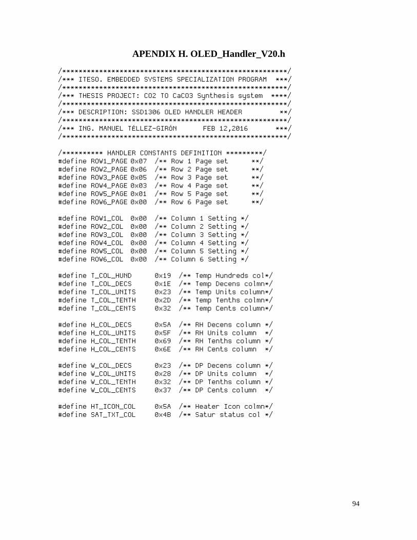
94
APENDIX H. OLED_Handler_V20.h
/*******************************************************/ /*** ITESO. EMBEDDED SYSTEMS SPECIALIZATION PROGRAM ***/ /*******************************************************/ /*** THESIS PROJECT: CO2 TO CaCO3 Synthesis system ****/ /*******************************************************/ /*** DESCRIPTION: SSD1306 OLED HANDLER HEADER **/ /*******************************************************/ /*** ING. MANUEL TÉLLEZ-GIRÓN FEB 12,2016 ***/ /*******************************************************/ /********** HANDLER CONSTANTS DEFINITION *********/ #define ROW1_PAGE 0x07 /** Row 1 Page set **/ #define ROW2_PAGE 0x06 /** Row 2 Page set **/ #define ROW3_PAGE 0x05 /** Row 3 Page set **/ #define ROW4_PAGE 0x03 /** Row 4 Page set **/ #define ROW5_PAGE 0x01 /** Row 5 Page set **/ #define ROW6_PAGE 0x00 /** Row 6 Page set **/ #define ROW1_COL 0x00 /** Column 1 Setting */ #define ROW2_COL 0x00 /** Column 2 Setting */ #define ROW3_COL 0x00 /** Column 3 Setting */ #define ROW4_COL 0x00 /** Column 4 Setting */ #define ROW5_COL 0x00 /** Column 5 Setting */ #define ROW6_COL 0x00 /** Column 6 Setting */ #define T_COL_HUND 0x19 /** Temp Hundreds col*/ #define T_COL_DECS 0x1E /** Temp Decens colmn*/ #define T_COL_UNITS 0x23 /** Temp Units column*/ #define T_COL_TENTH 0x2D /** Temp Tenths colmn*/ #define T_COL_CENTS 0x32 /** Temp Cents column*/ #define H_COL_DECS 0x5A /** RH Decens column */ #define H_COL_UNITS 0x5F /** RH Units column */ #define H_COL_TENTH 0x69 /** RH Tenths column */ #define H_COL_CENTS 0x6E /** RH Cents column */ #define W_COL_DECS 0x23 /** DP Decens column */ #define W_COL_UNITS 0x28 /** DP Units column */ #define W_COL_TENTH 0x32 /** DP Tenths column */ #define W_COL_CENTS 0x37 /** DP Cents column */ #define HT_ICON_COL 0x5A /** Heater Icon colmn*/ #define SAT_TXT_COL 0x4B /** Satur status col */
95
/************* FUNCTIONS PROTOTYPES **************/ void OLED_Clr_Scrn(void); void OLED_Setcursor(char pagenumber,char colnumber); void OLED_Writechar(char datachar[]); void Skeletonscr_Row1(void); /** First Skeleton row **/ void Skeletonscr_Row2(void); /** Second Skeleton row**/ void Skeletonscr_Row3(void); /** Third Skeleton row **/ void Skeletonscr_Row4(void); /** Fourth Skeleton row**/ void Skeletonscr_Row5(void); /** Fifth Skeleton row **/ void Skeletonscr_Row6(void); /** Sixth Skeleton row **/ void OLED_Chardisp(char ASCchar); /** Display ASCII char*/ void OLED_sat_status(void); /** Update satur signal */ void ASC_2_OLED(char ASCparam); /** ASCII 2 OLED Convert*/
96
APENDIX I. OLED_Chartable_V20.h
/*******************************************************/ /*** ITESO. EMBEDDED SYSTEMS SPECIALIZATION PROGRAM ****/ /*******************************************************/ /*** THESIS PROJECT: CO2 TO CaCO3 Synthesis system ****/ /*******************************************************/ /*** DESCRIPTION: SSD1306 OLED CHARACTER GEN TABLE **/ /*******************************************************/ /*** ING. MANUEL TÉLLEZ-GIRÓN FEB 12,2016 ****/ /*******************************************************/ #ORG 0x3600,0x36FF /** Place table at very end of HEX */ /************* NUMERIC CHARACTERS *****************/ char const ch_ZERO[5]= {0x7E,0x85,0xC1,0x7E,0x00}; // 0 char const ch_ONE[5]= {0x00,0x81,0xFF,0x01,0x00}; // 1 char const ch_TWO[5]= {0x47,0x89,0x91,0xA1,0x41}; // 2 char const ch_THREE[5]= {0x00,0x82,0x91,0xB1,0xCE}; // 3 char const ch_FOUR[5]= {0x18,0x28,0x48,0xFF,0x00}; // 4 char const ch_FIVE[5]= {0x00,0xF1,0x91,0x91,0x8E}; // 5 char const ch_SIX[5]= {0x00,0x7E,0x91,0x91,0x4E}; // 6 char const ch_SEVEN[5]= {0x80,0x8F,0xB0,0xC0,0x00}; // 7 char const ch_EIGHT[5]= {0x00,0x6E,0x91,0x91,0x6E}; // 8 char const ch_NINE[5]= {0x62,0x91,0x91,0x7E,0x00}; // 9 /************* SPECIAL CHARACTERS ******************/ char const ch_SPACE [5]= {0x00,0x00,0x00,0x00,0x00}; //{SPACE} char const ch_PERCENT[5]= {0x62,0x94,0x6E,0x19,0x26}; // % char const ch_DEGREE[5]= {0x60,0x90,0x90,0x60,0x00}; // º char const ch_ASTERISK[5]={0x54,0x38,0x38,0x54,0x00}; // * char const ch_PERIOD[5]= {0x00,0x03,0x03,0x00,0x00}; // . char const ch_ACTIVE[5]= {0x1F,0x1F,0x1F,0x1F,0x1F}; // char const ch_INACTIVE[5]={0x1F,0x11,0x11,0x11,0x1F}; // o /******** UPPERCASE ALPHABETIC CHARACTERS **********/ char const ch_A[5]= {0x3F,0xC8,0xC8,0x3F,0x00}; // A char const ch_C[5]= {0x7E,0x81,0x81,0x42,0x00}; // C char const ch_D[5]= {0xFF,0x81,0x81,0x7E,0x00}; // D char const ch_E[5]= {0xFF,0x91,0x81,0x81,0x00}; // E char const ch_F[5]= {0xFF,0x90,0x90,0x80,0x00}; // F char const ch_G[5]= {0x7E,0x81,0x89,0x4E,0x00}; // G char const ch_H[5]= {0xFF,0x10,0x10,0xFF,0x00}; // H char const ch_I[5]= {0x00,0x81,0xFF,0x81,0x00}; // I char const ch_M[5]= {0xFF,0x40,0x20,0x40,0xFF}; // M char const ch_N[5]= {0xFF,0x30,0x18,0xFF,0x00}; // N char const ch_O[5]= {0x7E,0x81,0x81,0x7E,0x00}; // O char const ch_P[5]= {0xFF,0x88,0x88,0x70,0x00}; // P char const ch_R[5]= {0xFF,0x88,0x8C,0x73,0x00}; // R char const ch_S[5]= {0x72,0x91,0x91,0x4E,0x00}; // S char const ch_T[5]= {0x80,0x80,0xFF,0x80,0x80}; // T char const ch_U[5]= {0x7E,0x01,0x01,0x7E,0x00}; // U char const ch_V[5]= {0xE0,0x1C,0x03,0x1C,0xE0}; // V
97
char const ch_W[5]= {0xFC,0x03,0x0C,0x03,0xFC}; // W char const ch_Y[5]= {0xC0,0x20,0x1F,0x20,0xC0}; // Y //char const ch_B[5]= {0x00,0x00,0x00,0x00,0x00}; // B //char const ch_J[5]= {0x00,0x00,0x00,0x00,0x00}; // J //char const ch_K[5]= {0x00,0x00,0x00,0x00,0x00}; // K //char const ch_L[5]= {0x00,0x00,0x00,0x00,0x00}; // L //char const ch_Q[5]= {0x00,0x00,0x00,0x00,0x00}; // Q //char const ch_X[5]= {0x00,0x00,0x00,0x00,0x00}; // X //char const ch_Z[5]= {0x00,0x00,0x00,0x00,0x00}; // Z /******** LOWERCASE ALPHABETIC CHARACTERS **********/ char const chm_c[5]= {0x1E,0x21,0x21,0x12,0x00}; // c char const chm_e[5]= {0x1E,0x29,0x29,0x1A,0x00}; // e char const chm_g[5]= {0x3E,0x41,0x49,0x2E,0x00}; // g char const chm_h[5]= {0x7F,0x10,0x10,0x0F,0x00}; // h char const chm_i[5]= {0x01,0x5F,0x01,0x00,0x00}; // i char const chm_l[5]= {0x00,0x3F,0x01,0x00,0x00}; // l char const chm_m[5]= {0x1F,0x20,0x1F,0x20,0x1F}; // m char const chm_o[5]= {0x1E,0x21,0x21,0x1E,0x00}; // o char const chm_p[5]= {0x00,0x3F,0x24,0x24,0x18}; // p char const chm_r[5]= {0x3F,0x10,0x20,0x10,0x00}; // r char const chm_t[5]= {0x10,0x7E,0x11,0x02,0x00}; // t //char const chm_a[5]= {0x00,0x00,0x00,0x00,0x00}; // a //char const chm_b[5]= {0x00,0x00,0x00,0x00,0x00}; // b //char const chm_d[5]= {0x00,0x00,0x00,0x00,0x00}; // d //char const chm_f[5]= {0x08,0x3F,0x48,0x48,0x20}; // f //char const chm_j[5]= {0x00,0x00,0x00,0x00,0x00}; // j //char const chm_k[5]= {0x00,0x00,0x00,0x00,0x00}; // k //char const chm_n[5]= {0x00,0x00,0x00,0x00,0x00}; // n //char const chm_q[5]= {0x00,0x00,0x00,0x00,0x00}; // q //char const chm_s[5]= {0x00,0x00,0x00,0x00,0x00}; // s //char const chm_u[5]= {0x00,0x00,0x00,0x00,0x00}; // u //char const chm_v[5]= {0x00,0x00,0x00,0x00,0x00}; // v //char const chm_w[5]= {0x00,0x00,0x00,0x00,0x00}; // w //char const chm_x[5]= {0x00,0x00,0x00,0x00,0x00}; // x //char const chm_y[5]= {0x00,0x00,0x00,0x00,0x00}; // y //char const chm_z[5]= {0x00,0x00,0x00,0x00,0x00}; // z
98
APENDIX J. CO2_Synth_Tasks_V20.c
/*******************************************************/ /*** ITESO. EMBEDDED SYSTEMS SPECIALIZATION PROGRAM ****/ /*******************************************************/ /*** THESIS PROJECT: CO2 TO CaCO3 Synthesis system ****/ /*******************************************************/ /*** DESCRIPTION: RTOS SCHEDULER TASKS C FILE ****/ /*******************************************************/ /*** ING. MANUEL TÉLLEZ-GIRÓN JAN 14,2016 ****/ /*******************************************************/ int1 heatbutton_press=FALSE; /* Flag: Forced ht button press **/ int1 forcedheating= FALSE; /* Flag: Forced ht status flag **/ /*************************************************/ /** brief TASK 425 mS: Forced heater handler **/ /** author Ing. Manuel Téllez-Girón **/ /** param void **/ /** return void **/ /*************************************************/ #task(Rate=425ms,Max=425mS) void CO2_RTOS_425mS_Task() { if(!input(BUTTON_HEAT)) /* Button press*/ { if(!heatbutton_press) /* Prev release*/ { heatbutton_press=TRUE; /* Prev active */ if(!input(LED_MANHEAT)) /* Heater =OFF */ { Output_HIGH(LED_MANHEAT); /*** Heat= ON **/ SHT11_Command(CMD_ACT_DESAT); OLED_Setcursor(ROW6_PAGE,HT_ICON_COL); OLED_Chardisp(0x00); OLED_forced_heat(); Output_HIGH(LED_HEATER); forcedheating=TRUE; } else /* Heater= ON */ { Output_LOW(LED_MANHEAT); /*** Heat= OFF**/ SHT11_Command(CMD_DIS_DESAT); OLED_Setcursor(ROW6_PAGE,HT_ICON_COL); OLED_Chardisp(0x01); Output_LOW(LED_HEATER); forcedheating=FALSE; } } else /* Still pressed*/ {} /* No action */ }
99
else heatbutton_press=FALSE; /* Yes released */ } /*************************************************/ /** brief TASK1700mS: Periodic sense/process **/ /** author Ing. Manuel Téllez-Girón **/ /** param void **/ /** return void **/ /*************************************************/ #task(Rate=1700ms,Max=425mS) void CO2_RTOS_1700mS_Task( ) { Output_HIGH(LED_PROCESS); /** Process start flag */ SHT11_Command(CMD_RD_Temp); /* Read Temp °C */ SHT11_Command(CMD_RD_RH); /* Read RH% */ Calc_DewPoint(); /* Calculate Dew Point */ Calc_DP4Disp(); /* Calculate displ DP */ OLED_Temp_Upd(); /* OLED Refresh Temp */ OLED_RH_Upd(); /* OLED Refresh RH% */ OLED_DP_Upd(); /* OLED Refresh DP */ if(!forcedheating) { SHT11_Saturation_Chk(); /** Check sensor satur */ OLED_Satur_Upd(); /* OLED Sat icon update*/ } Output_LOW(LED_PROCESS); /** Process End flag */ }
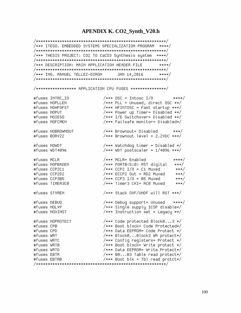
100
APENDIX K. CO2_Synth_V20.h
/*******************************************************/ /*** ITESO. EMBEDDED SYSTEMS SPECIALIZATION PROGRAM ****/ /*******************************************************/ /*** THESIS PROJECT: CO2 TO CaCO3 Synthesis system ****/ /*******************************************************/ /*** DESCRIPTION: MAIN APPLICATION HEADER FILE ****/ /*******************************************************/ /*** ING. MANUEL TÉLLEZ-GIRÓN JAN 14,2016 ****/ /*******************************************************/ /***************** APPLICATION CPU FUSES ***************/ #fuses INTRC_IO /*** OSC = Intosc I/O ****/ #fuses NOPLLEN /*** PLL = Unused, direct OSC **/ #fuses NOHFOFST /*** HFINTOSC = Fast startup ***/ #fuses NOPUT /*** Power up Timer= Disabled **/ #fuses NOIESO /*** I/E Switchover= Disabled **/ #fuses NOFCMEN /*** Failsafe monitor= Disabled*/ #fuses NOBROWNOUT /*** Brownout= Disabled ***/ #fuses BORV22 /*** Brownout level = 2.2VDC ***/ #fuses NOWDT /*** Watchdog timer = Disabled */ #fuses WDT4096 /*** WDT postscaler = 1/4096 ***/ #fuses MCLR /*** MCLR= Enabled ****/ #fuses NOPBADEN /*** PORTB<5:0> RST digital ***/ #fuses CCP2C1 /*** CCP2 I/O = C1 Muxed ***/ #fuses CCP2D2 /*** ECCP2 Out = RD2 Muxed ***/ #fuses CCP3B5 /*** CCP3 I/O = B5 Muxed ***/ #fuses TIMER3C0 /*** Timer3 CKI= RC0 Muxed ***/ #fuses STVREN /*** Stack OVF/UNDF will RST ***/ #fuses DEBUG /*** Debug support= Unused ****/ #fuses NOLVP /*** Single supply ICSP disable*/ #fuses NOXINST /*** Instruction set = Legacy **/ #fuses NOPROTECT /*** Code protected Block0...3 */ #fuses CPB /*** Boot block= Code Protected*/ #fuses CPD /*** Data EEPROM= Code Protect */ #fuses WRT /*** Block0...Block3 WR protect*/ #fuses WRTC /*** Config registers= Protect */ #fuses WRTB /*** Boot block= Write protect */ #fuses WRTD /*** Data EEPROM= Write Protect*/ #fuses EBTR /*** B0...B3 Table read protect*/ #fuses EBTRB /*** Boot blk = Tbl read protct*/ /*******************************************************/
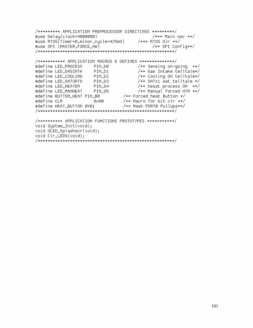
101
/********* APPLICATION PREPROCESSOR DIRECTIVES *********/ #use Delay(clock=4000000) /*** Main osc **/ #use RTOS(Timer=0,minor_cycle=425mS) /*** RTOS Dir **/ #use SPI (MASTER,FORCE_HW) /** SPI Config**/ /*******************************************************/ /*********** APPLICATION MACROS & DEFINES **************/ #define LED_PROCESS PIN_D0 /** Sensing on-going **/ #define LED_GASINTK PIN_D1 /** Gas Intake telltale*/ #define LED_COOLING PIN_D2 /** Cooling ON telltale*/ #define LED_SATURTD PIN_D3 /** SHT11 sat telltale */ #define LED_HEATER PIN_D4 /** Desat process ON **/ #define LED_MANHEAT PIN_D5 /** Manual forced HTR **/ #define BUTTON_HEAT PIN_B0 /** Forced heat Button */ #define CLR 0x00 /** Macro for bit clr **/ #define HEAT_BUTTON 0X01 /** Mask PORTB Pullups**/ /*******************************************************/ /********** APPLICATION FUNCTIONS PROTOTYPES ***********/ void System_Init(void); void OLED_Splashscr(void); void Clr_LEDS(void); /*******************************************************/

102
APENDIX L. CO2_Synth_V20.c
/*******************************************************/ /*** ITESO. EMBEDDED SYSTEMS SPECIALIZATION PROGRAM ***/ /*******************************************************/ /*** THESIS PROJECT: CO2 TO CaCO3 Synthesis system ****/ /*******************************************************/ /*** DESCRIPTION: MAIN APPLICATION C FILE ***/ /*******************************************************/ /*** ING. MANUEL TÉLLEZ-GIRÓN FEB 12,2016 ***/ /*******************************************************/ /***************** INCLUDE FILES ***********************/ #include "18LF46K22.h" /*** Device Header ****/ #include "CO2_Synth_V20.h" /*** Main app header ***/ #include "SHT11_Handler_V20.c" /*** SHT11 sensor handr*/ #include "OLED_Handler_V20.c" /*** OLED Disp handler */ #include "CO2_Synth_Tasks_V20.c" /*** RTOS Tasks ****/ /*******************************************************/ /******************* MAIN PROGRAM LOOP *****************/ void main() { System_Init(); /** Sensor warmup time */ SHT11_Init(); /** Sensor initialize **/ OLED_Startup(); /** OLED Initialization*/ OLED_Clr_Scrn(); /** Clear OLED screen **/ OLED_Splashscr(); /** Build OLED mainscr**/ SHT11_Command(CMD_Soft_RST); /** Issue a Soft RST **/ SHT11_Command(CMD_WR_Status); /** Configure interface*/ Output_D(CLR); /** Clears all LEDs */ RTOS_Run(); /*** RTOS Dispatcher ***/ } /*************************************************/ /** brief CO2 Synth Application Initialization*/ /** author Ing. Manuel Téllez-Girón **/ /** param void **/ /** return void **/ /*************************************************/ void System_Init(void) { Setup_ADC_ports(NO_ANALOGS); Setup_Comparator(NC_NC_NC_NC); Setup_SPI(SPI_MASTER|SPI_SCK_IDLE_HIGH|SPI_XMIT_L_TO_H|SPI_CLK_DIV_16); Setup_CCP1(CCP_OFF); Output_LOW(SPI_SCLK); Output_HIGH(SPI_RES); Output_LOW(SPI_SDIN); Output_HIGH(SPI_CS); Port_B_Pullups(HEAT_BUTTON); }
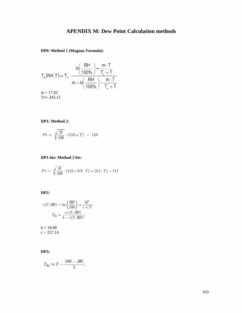
103
APENDIX M: Dew Point Calculation methods
DP0: Method 1 (Magnus Formula):
m = 17.62
TN= 243.12
DP1: Method 2:
DP1-bis: Method 2 bis:
DP2:
b = 18.68
c = 257.14
DP3:
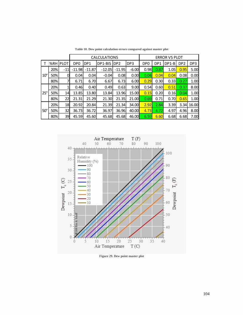
104
Table 10. Dew point calculation errors compared against master plot
Figure 29. Dew point master plot
T %RH PLOT DP0 DP1 DP1-BIS DP2 DP3 DP0 DP1 DP1-B DP2 DP3
20% -11 -11.98 -11.87 -12.05 -11.95 -6.00 0.98 0.87 1.05 0.95 5.00
50% 0 0.04 0.04 -0.04 0.08 0.00 0.04 0.04 0.04 0.08 0.00
80% 7 6.71 6.70 6.67 6.73 6.00 0.29 0.30 0.33 0.27 1.00
20% 1 0.46 0.40 0.49 0.63 9.00 0.54 0.60 0.51 0.37 8.00
50% 14 13.85 13.80 13.84 13.96 15.00 0.15 0.20 0.16 0.04 1.00
80% 22 21.31 21.29 21.30 21.35 21.00 0.69 0.71 0.70 0.65 1.00
20% 18 20.92 20.84 21.39 21.34 34.00 2.92 2.84 3.39 3.34 16.00
50% 32 36.73 36.72 36.97 36.96 40.00 4.73 4.72 4.97 4.96 8.00
80% 39 45.59 45.60 45.68 45.68 46.00 6.59 6.60 6.68 6.68 7.00
CALCULATIONS ERROR VS PLOT
10°
25°
50°