Shader generation and compilation for a programmable GPU Student: Jordi Roca Monfort Advisor:...
40
Shader generation and compilation for a programmable GPU Student: Jordi Roca Monfort Advisor: Agustín Fernández Jiménez Co-advisor: Carlos González Rodríguez
-
Upload
christian-lane -
Category
Documents
-
view
219 -
download
0
Transcript of Shader generation and compilation for a programmable GPU Student: Jordi Roca Monfort Advisor:...
Shader generation and compilation for a programmable GPU
Student: Jordi Roca MonfortAdvisor: Agustín Fernández JiménezCo-advisor: Carlos González Rodríguez
Outline
Introduction. Background. Goals. Design and implementation. Conclusions.

Introduction
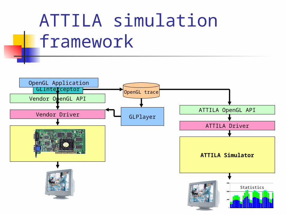
ATTILA simulation framework
Vendor OpenGL API
Vendor Driver
GLInterceptorOpenGL Application
ATTILA OpenGL API
ATTILA Driver
ATTILA Simulator
OpenGL trace
Statistics
GLPlayer
ATTILA Driver
ATTILA Simulator
Statistics
Simulates last generation of 3D graphics boards (programmable
GPUs)
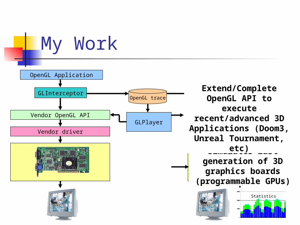
My Work
ATTILA OpenGL API
OpenGL Application
OpenGL trace
Vendor OpenGL API
Vendor driver
GLInterceptor
GLPlayer
Extend/Complete OpenGL API to
execute recent/advanced 3D
Applications (Doom3, Unreal Tournament,
etc)
Background
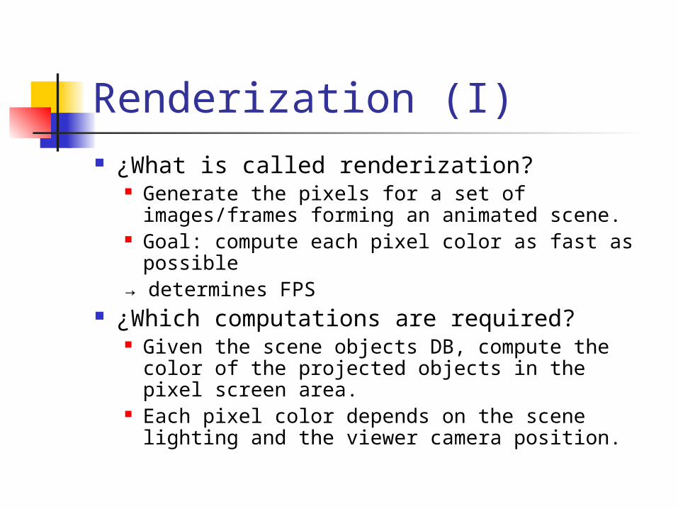
Renderization (I) ¿What is called renderization?
Generate the pixels for a set of images/frames forming an animated scene.
Goal: compute each pixel color as fast as possible
→ determines FPS ¿Which computations are required?
Given the scene objects DB, compute the color of the projected objects in the pixel screen area.
Each pixel color depends on the scene lighting and the viewer camera position.
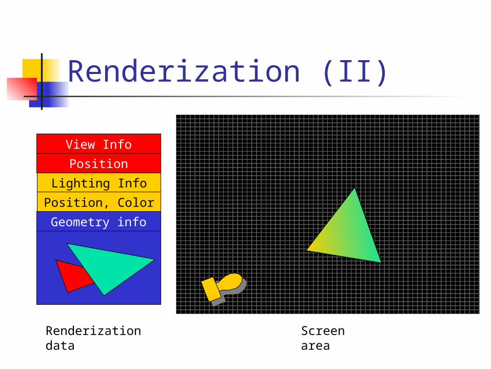
Renderization (II)
Position
View Info
Renderization data
Geometry info
Position, Color
Lighting Info
Screen area
Renderization approaches For each pixel (x,y) compute physical interaction
between the lights and objects in scene: RayTracing, Radiosity, Photon Map Very expensive pixel computation:
Global lighting (shadows, indirect reflections among objects)
Interaction between objects and lights are computed only in vertices and for each pixel (x,y) the corresponding value is approached.
Direct Rendering (3D graphics boards, 3D game consoles, etc.).
Only direct illumination from light sources (Each vertex color is independent)
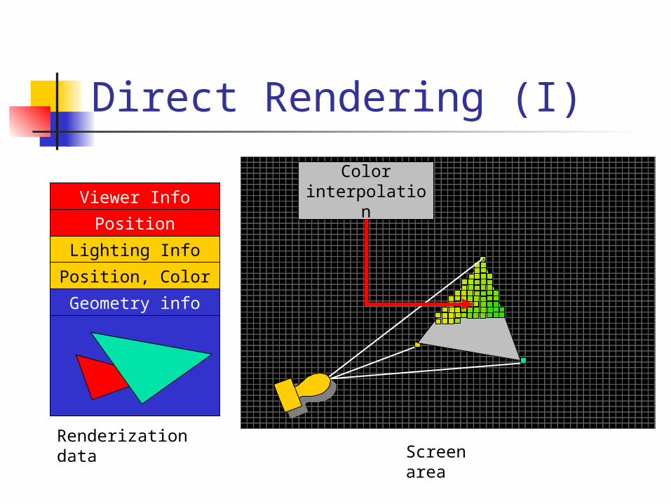
Direct Rendering (I)
Position
Viewer Info
Renderization data
Geometry info
Position, Color
Lighting Info
Screen area
Color interpolation
Direct Rendering (II) The higher density of vertices, the more
realistic lighting. In addition, more vertices are required
to improve level of detail in surfaces. Thus:
▲realism→ ▲vertices→ ▲computation→ ▼FPS
Solution: Specify surface using less vertices and Specify surface details using textures.
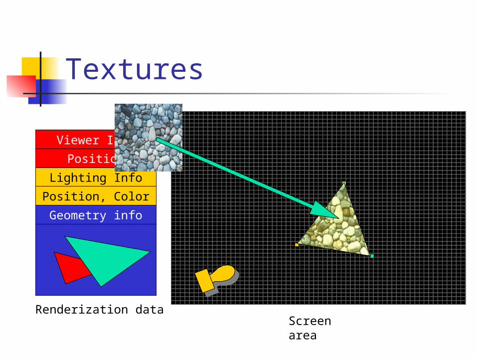
Textures
Renderization data
Position
Viewer Info
Geometry info
Position, Color
Lighting Info
Screen area
Textures
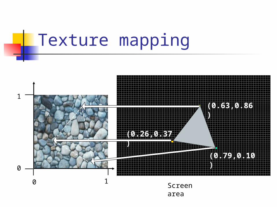
Texture mapping
Screen area0 1
0
1(0.63,0.86)
(0.26,0.37)
(0.79,0.10)
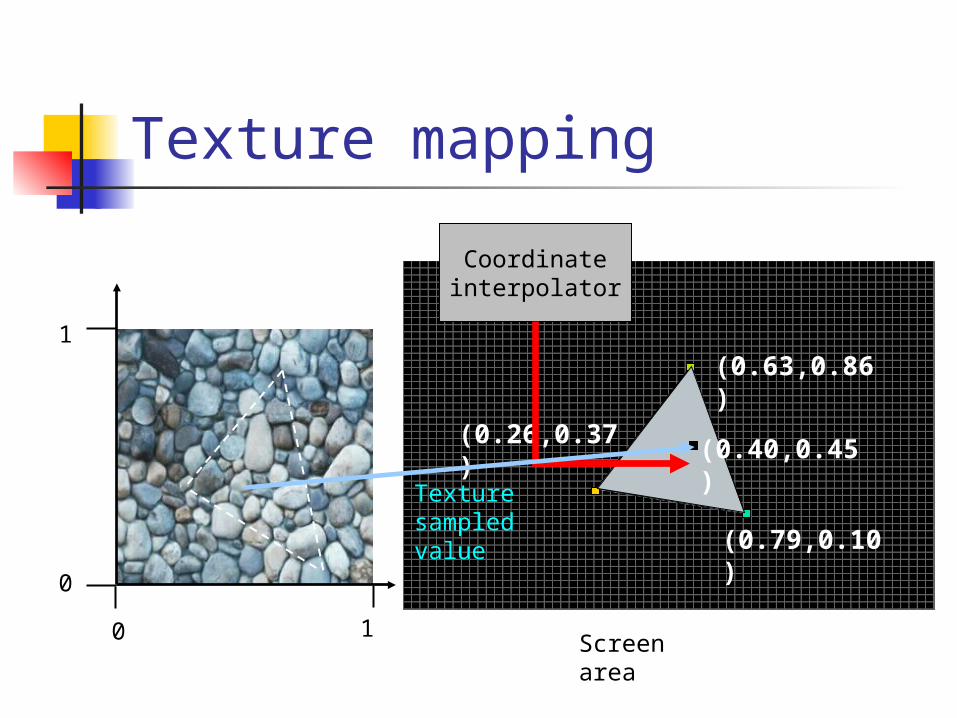
Texture mapping
Screen area0 1
0
1(0.63,0.86)
(0.26,0.37)
(0.79,0.10)
Coordinate interpolator
(0.40,0.45)Texture
sampled value
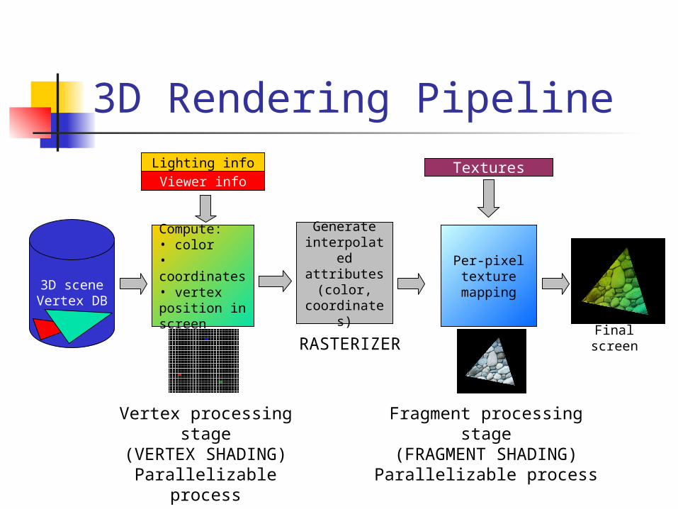
3D Rendering Pipeline
Generate interpolated attributes
(color, coordinates
)
Per-pixel texture
mapping
Compute:• color• coordinates• vertex position in screen Final
screen
3D scene Vertex DB
Viewer infoLighting info Textures
Vertex processing stage(VERTEX SHADING)
Parallelizable process
Fragment processing stage
(FRAGMENT SHADING)Parallelizable process
RASTERIZER
3D RP Implementation Implementations
Software: Mesa 3D Graphics Library (OpenGL).
Software + hardware acceleration: Vendor OpenGL, Direct3D, Xbox, PlayStation,
etc. Work distribution between CPU y graphics board
transparently to the applications.

3D accelerators evolution 2D accelerators (pre Voodo) <1996
3D accelerators (3Dfx Voodo) 1996
Graphical Processor Units (GeForce) 1999
Programmable GPUs (GeForce 3) 2001
Rasterizer FSVSFinal
screenBD
CPU
VGA
Rasterizer FSVSFinal
screenBD
CPU
3D accelerators
Rasterizer FSVSFinal
screenBD
CPU
GPU
Rasterizer FSVSFinal
screenBD
CPU
PGPU
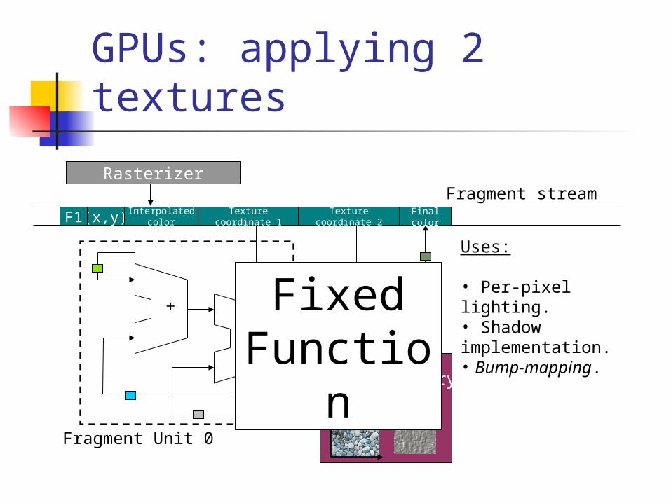
GPUs: applying 2 textures
Rasterizer
(x,y) Interpolatedcolor
Texture coordinate 1 Final colorF1
Fragment streamTexture coordinate 2
+
Fragment Unit 0
Texture Memory
*
Fixed Functio
n
Uses:
• Per-pixel lighting.• Shadow implementation.• Bump-mapping.
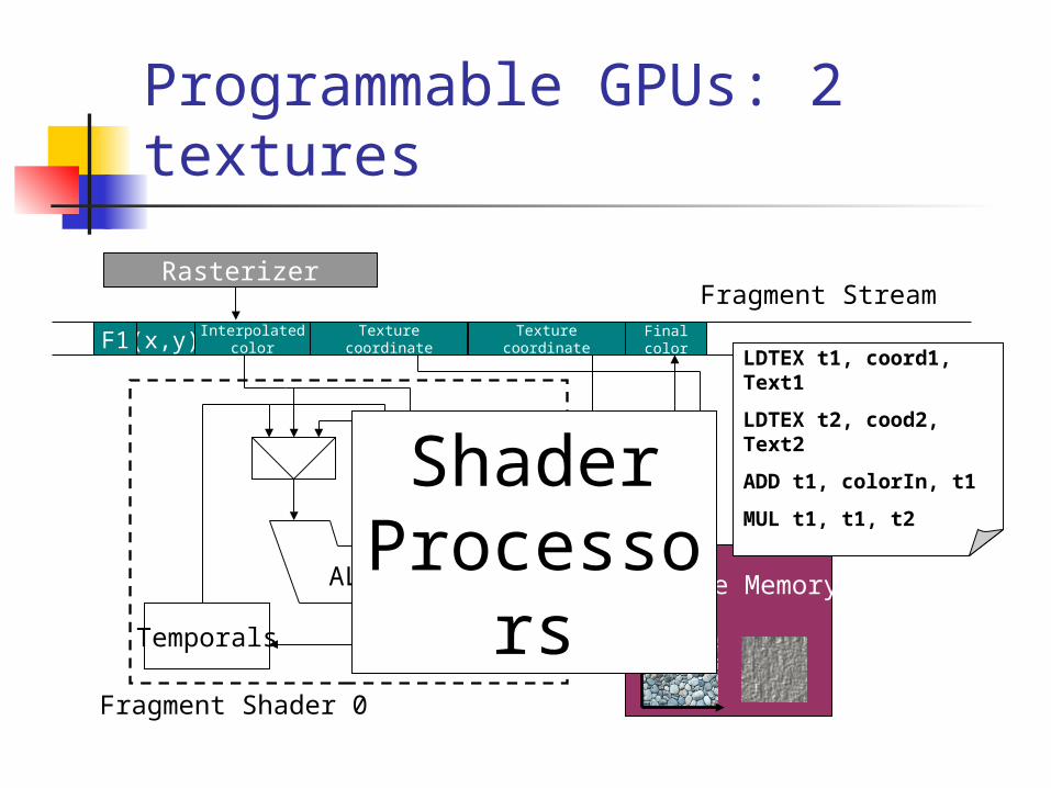
Programmable GPUs: 2 textures
Rasterizer
(x,y) Interpolatedcolor
Texture coordinate Final colorF1
Fragment Stream
Texture coordinate
Fragment Shader 0
Texture MemoryALU
Temporals
Shader Processor
s
LDTEX t1, coord1, Text1
LDTEX t2, cood2, Text2
ADD t1, colorIn, t1
MUL t1, t1, t2
Shader Processors SP execute small programs (shaders) using
vectorial and scalar instructions, that define the computation in the following stages:
Vertex processing: Vertex Shader Lighting computation On-screen vertex projection Texture coordinates generation.
Fragment processing: Fragment Shader Texture color fetch and blending. FOG
It is like a GPU supporting “infinite visualization effects” not supported in previous graphics boards generations.
Goals
Goals Implement all the necessary modules in
the OpenGL API to: Support new real 3D applications using
shaders in our simulation framework. Support also for old applications using FF and
applications combining both shaders and FF.
Idea: Perform Fixed Function emulation through generating
equivalent shaders for SP.

Things to do
Implement shader support in our OpenGL API: Using the most used shader
programming language by 3D apps: ARB_vertex_program y ARB_fragment_program
Study how to express FF functions in terms of shaders (pre-study phase).

Design and implementation
Fixed Function emulation
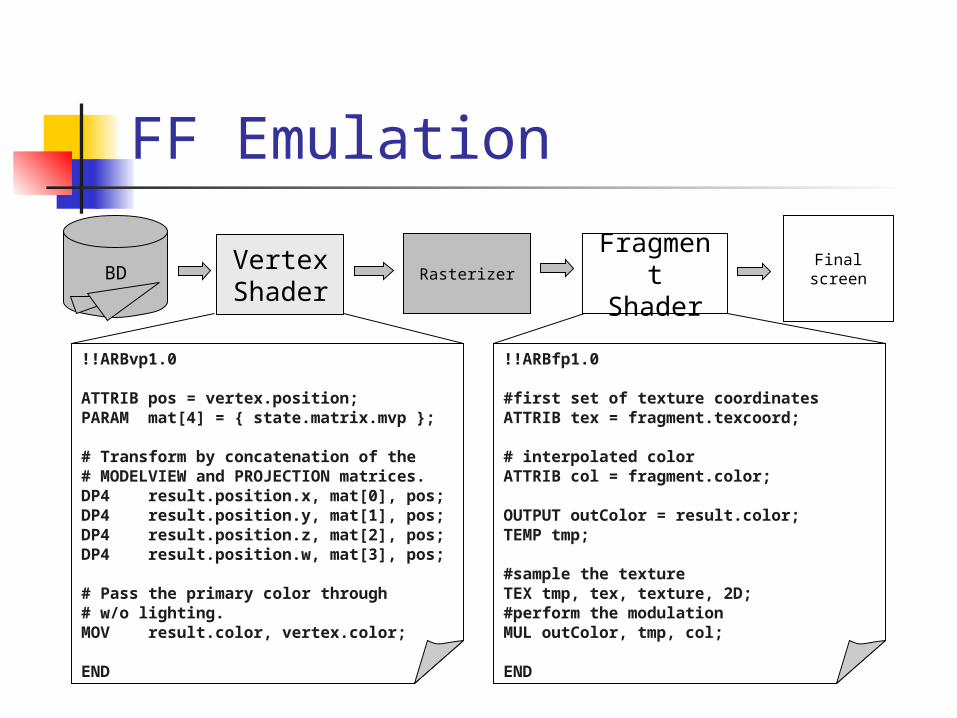
FF Emulation
RasterizerFragment Shader
Vertex Shader
Final screenBD
!!ARBvp1.0
ATTRIB pos = vertex.position;PARAM mat[4] = { state.matrix.mvp };
# Transform by concatenation of the# MODELVIEW and PROJECTION matrices.DP4 result.position.x, mat[0], pos;DP4 result.position.y, mat[1], pos;DP4 result.position.z, mat[2], pos;DP4 result.position.w, mat[3], pos;
# Pass the primary color through # w/o lighting.MOV result.color, vertex.color;
END
!!ARBfp1.0
#first set of texture coordinatesATTRIB tex = fragment.texcoord;
# interpolated colorATTRIB col = fragment.color;
OUTPUT outColor = result.color;TEMP tmp;
#sample the textureTEX tmp, tex, texture, 2D;#perform the modulationMUL outColor, tmp, col; END
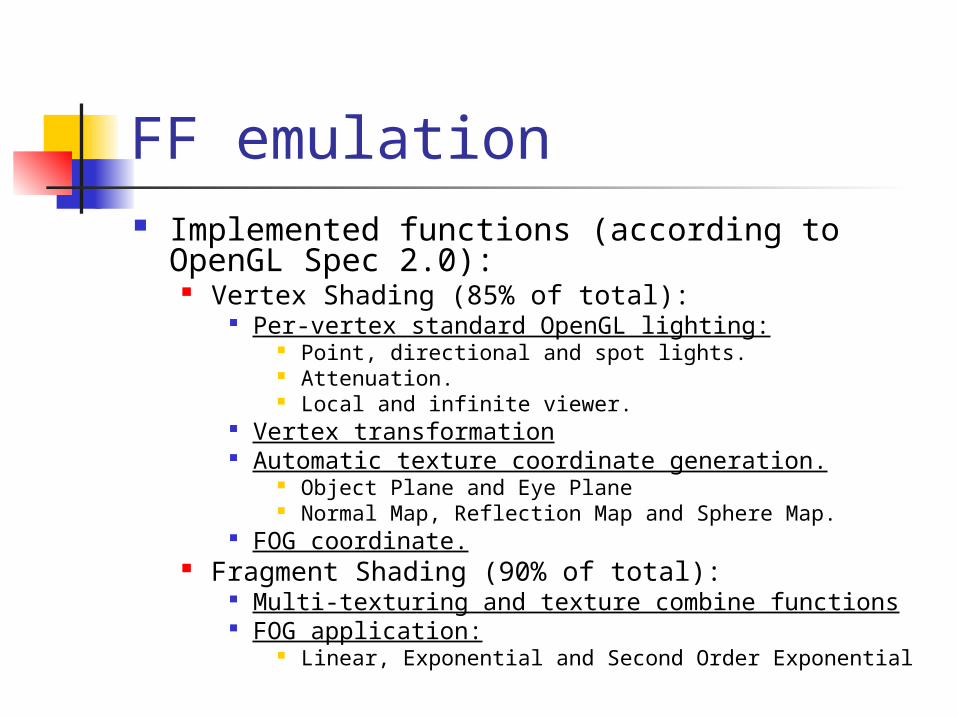
FF emulation Implemented functions (according to OpenGL
Spec 2.0): Vertex Shading (85% of total):
Per-vertex standard OpenGL lighting: Point, directional and spot lights. Attenuation. Local and infinite viewer.
Vertex transformation Automatic texture coordinate generation.
Object Plane and Eye Plane Normal Map, Reflection Map and Sphere Map.
FOG coordinate. Fragment Shading (90% of total):
Multi-texturing and texture combine functions FOG application:
Linear, Exponential and Second Order Exponential

FF emulation example FOG application:
Algorithm: For each pixel, perform linear interpolation between the original and the fog color, accoding to the distance from the object to the viewer.
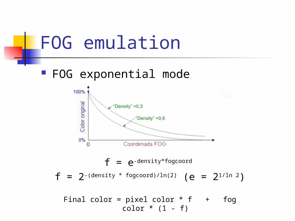
FOG emulation FOG exponential mode
f = e-density*fogcoord
f = 2-(density * fogcoord)/ln(2) (e = 21/ln 2)
Final color = pixel color * f + fog color * (1 - f)
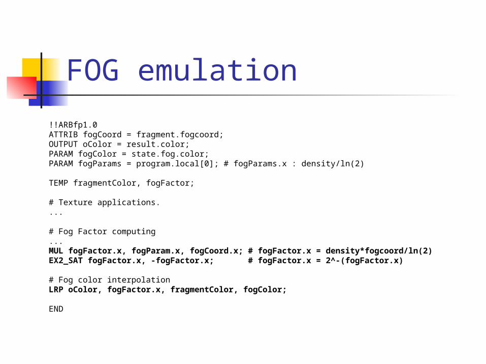
FOG emulation
!!ARBfp1.0ATTRIB fogCoord = fragment.fogcoord;OUTPUT oColor = result.color;PARAM fogColor = state.fog.color;PARAM fogParams = program.local[0]; # fogParams.x : density/ln(2)
TEMP fragmentColor, fogFactor;
# Texture applications....
# Fog Factor computing...MUL fogFactor.x, fogParam.x, fogCoord.x; # fogFactor.x = density*fogcoord/ln(2)EX2_SAT fogFactor.x, -fogFactor.x; # fogFactor.x = 2^-(fogFactor.x)
# Fog color interpolationLRP oColor, fogFactor.x, fragmentColor, fogColor;
END
ARB compilers
ARB compilers
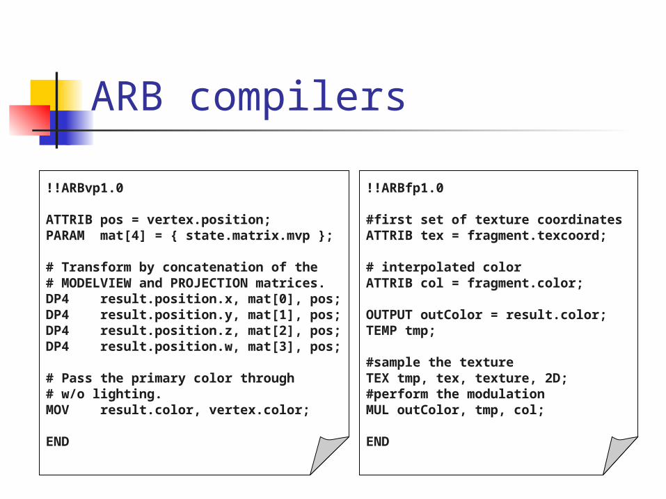
!!ARBvp1.0
ATTRIB pos = vertex.position;PARAM mat[4] = { state.matrix.mvp };
# Transform by concatenation of the# MODELVIEW and PROJECTION matrices.DP4 result.position.x, mat[0], pos;DP4 result.position.y, mat[1], pos;DP4 result.position.z, mat[2], pos;DP4 result.position.w, mat[3], pos;
# Pass the primary color through # w/o lighting.MOV result.color, vertex.color;
END
!!ARBfp1.0
#first set of texture coordinatesATTRIB tex = fragment.texcoord;
# interpolated colorATTRIB col = fragment.color;
OUTPUT outColor = result.color;TEMP tmp;
#sample the textureTEX tmp, tex, texture, 2D;#perform the modulationMUL outColor, tmp, col; END
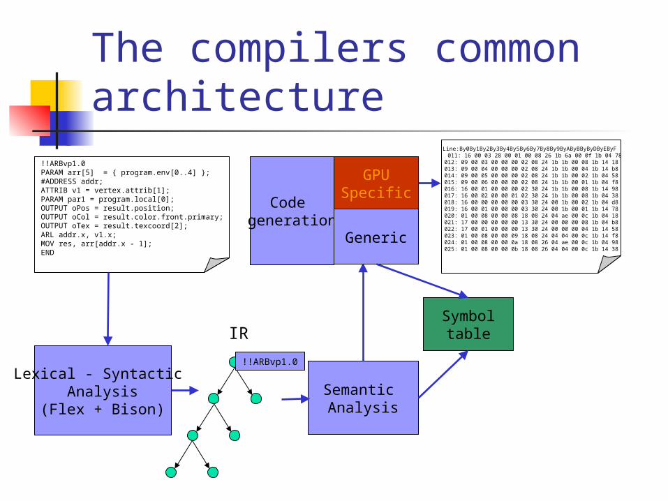
The compilers common architecture
!!ARBvp1.0PARAM arr[5] = { program.env[0..4] };#ADDRESS addr;ATTRIB v1 = vertex.attrib[1];PARAM par1 = program.local[0];OUTPUT oPos = result.position;OUTPUT oCol = result.color.front.primary;OUTPUT oTex = result.texcoord[2];ARL addr.x, v1.x;MOV res, arr[addr.x - 1];END
Lexical - Syntactic Analysis
(Flex + Bison)
!!ARBvp1.0
IR
Semantic Analysis
Symboltable
Code generation
GPUSpecific
Generic
Line:By0By1By2By3By4By5By6By7By8By9ByAByBByByDByEByF 011: 16 00 03 28 00 01 00 08 26 1b 6a 00 0f 1b 04 78 012: 09 00 03 00 00 00 02 08 24 1b 1b 00 08 1b 14 18 013: 09 00 04 00 00 00 02 08 24 1b 1b 00 04 1b 14 b8 014: 09 00 05 00 00 00 02 08 24 1b 1b 00 02 1b 04 58 015: 09 00 06 00 00 00 02 08 24 1b 1b 00 01 1b 04 f8 016: 16 00 01 00 00 00 02 30 24 1b 1b 00 08 1b 14 98 017: 16 00 02 00 00 01 02 30 24 1b 1b 00 08 1b 04 38 018: 16 00 00 00 00 00 03 30 24 00 1b 00 02 1b 04 d8 019: 16 00 01 00 00 00 03 30 24 00 1b 00 01 1b 14 78 020: 01 00 08 00 00 08 18 08 24 04 ae 00 0c 1b 04 18 021: 17 00 00 00 00 00 13 30 24 00 00 00 08 1b 04 b8 022: 17 00 01 00 00 00 13 30 24 00 00 00 04 1b 14 58 023: 01 00 08 00 00 09 18 08 24 04 04 00 0c 1b 14 f8 024: 01 00 08 00 00 0a 18 08 26 04 ae 00 0c 1b 04 98 025: 01 00 08 00 00 0b 18 08 26 04 04 00 0c 1b 14 38
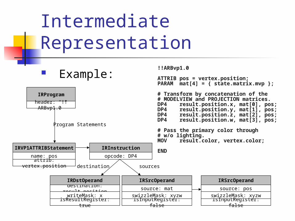
Intermediate Representation Example:
!!ARBvp1.0
ATTRIB pos = vertex.position;PARAM mat[4] = { state.matrix.mvp };
# Transform by concatenation of the# MODELVIEW and PROJECTION matrices.DP4 result.position.x, mat[0], pos;DP4 result.position.y, mat[1], pos;DP4 result.position.z, mat[2], pos;DP4 result.position.w, mat[3], pos;
# Pass the primary color through # w/o lighting.MOV result.color, vertex.color;
END
IRProgram
header: “!!ARBvp1.0”
IRVP1ATTRIBStatement
name: posattrib: vertex.position
Program Statements
IRInstruction
opcode: DP4
destination: result.position
IRDstOperand
writeMask: xisResultRegister: true
source: mat
IRSrcOperand
swizzleMask: xyzwisInputRegister: false
destination sources
source: pos
IRSrcOperand
swizzleMask: xyzwisInputRegister: false
Semantic analysis and generic code generation
Features: Implemented using the visitor pattern. Decouples IR from the different
operations involved in each compiler phase.
Allows using a common analyzer and a common code generator for both program types.
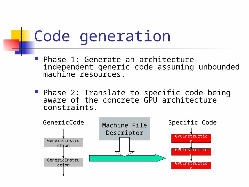
Code generation Phase 1: Generate an architecture-independent
generic code assuming unbounded machine resources.
Phase 2: Translate to specific code being aware of the concrete GPU architecture constraints.
GenericInstruction
GenericCode
GenericInstruction
Machine File Descriptor
GPUInstruction
Specific Code
GPUInstruction
GPUInstruction

Conclusions

Conclusions Achieved goals:
Now, the OpenGL API implementation supports:
Fixed Function emulation Of almost the entire set of functions of VS and FS
stages (the most important ones).
Shader compilation for ARB_vertex_program and ARB_fragment_program specifications.
Both compilers share most of the implementation. Clear separation between generic and specific stages.
Future work
Support/include other 3D RP parts (i.e. interpolation) like programables stages to reduce hardware complexity and power consumption (embedded systems).
Implement high-level shading languages compilers (GLSlang, HLSL).

End of the presentation