SFE-25/50/75 & HFE-25/50 - Euromate · • Always use tools, parts, materials, lubricants and...
14
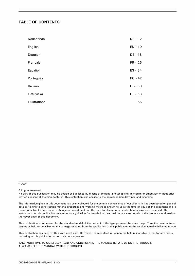
www.plymovent.com NL Stationaire unit met elektrostatisch filter EN Stationary unit with electrostatic filter DE Stationäre Anlage mit elektrostatischem Filter FR Unité stationnaire avec filtre électrostatique ES Aspirador estacionario con filtro electrostático PO Módulo de filtragem electrostática IT Unità pensile con filtrazione elettrostatica LT Stacionarus įrenginys su elektrostatiniu filtru NL Gebruikershandleiding EN User manual DE Betriebsanleitung FR Manuel opérateur ES Instrucciones para el uso PO Manual do utilizador IT Manuale d’uso LT Vartotojo instrukcija SFE-25/50/75 & HFE-25/50
Transcript of SFE-25/50/75 & HFE-25/50 - Euromate · • Always use tools, parts, materials, lubricants and...
www.plymovent.com
NL Stationaireunitmetelektrostatischfilter
EN Stationaryunitwithelectrostaticfilter
DE Stationäre Anlage mit elektrostatischem Filter
FR Unitéstationnaireavecfiltreélectrostatique
ES Aspiradorestacionarioconfiltroelectrostático
PO Módulodefiltragemelectrostática
IT Unitàpensileconfiltrazioneelettrostatica
LT Stacionarusįrenginyssuelektrostatiniufiltru
NL Gebruikershandleiding
EN User manual
DE Betriebsanleitung
FR Manuel opérateur
ES Instrucciones para el uso
PO Manual do utilizador
IT Manuale d’uso
LT Vartotojo instrukcija
SFE-25/50/75 & HFE-25/50
0508080010/SFE-HFE/010111/G 1
TABLE OF CONTENTS
Nederlands NL - 2
English EN - 10
Deutsch DE - 18
Français FR - 26
Español ES - 34
Português PO - 42
Italiano IT - 50
Lietuviska LT - 58
Illustrations 66
© 2004
All rights reserved.No part of this publication may be copied or published by means of printing, photocopying, microfilm or otherwise without prior written consent of the manufacturer. This restriction also applies to the corresponding drawings and diagrams.
The information given in this document has been collected for the general convenience of our clients. It has been based on general data pertaining to construction material properties and working methods known to us at the time of issue of the document and is therefore subject at any time to change or amendment and the right to change or amend is hereby expressly reserved. The instructions in this publication only serve as a guideline for installation, use, maintenance and repair of the product mentioned on the cover page of this document.
This publication is to be used for the standard model of the product of the type given on the cover page. Thus the manufacturer cannot be held responsible for any damage resulting from the application of this publication to the version actually delivered to you.
This publication has been written with great care. However, the manufacturer cannot be held responsible, either for any errors occurring in this publication or for their consequences.
TAKE YOUR TIME TO CAREFULLY READ AND UNDERSTAND THE MANUAL BEFORE USING THE PRODUCT.ALWAYS KEEP THE MANUAL WITH THE PRODUCT.
0508080010/SFE-HFE/010111/G EN - 10
ENGLISH1 PREFACE
Using this manualThis manual is intended to be used as a work of reference for professional, well trained and authorised users to be able to safely install, use, maintain and repair the product mentioned on the cover of this document. The figures referred to in the text, can be found in the back of this manual.
Pictograms and symbolsThe following pictograms and symbols are used on the product and in this manual.
Service and technical supportFor information about specific adjustments, maintenance or repair jobs which are not dealt with in this manual, please contact the supplier of the product. He will always be willing to help you. Make sure you have the following specifications at hand:- product name- serial number
These data can be found on the identification plate.
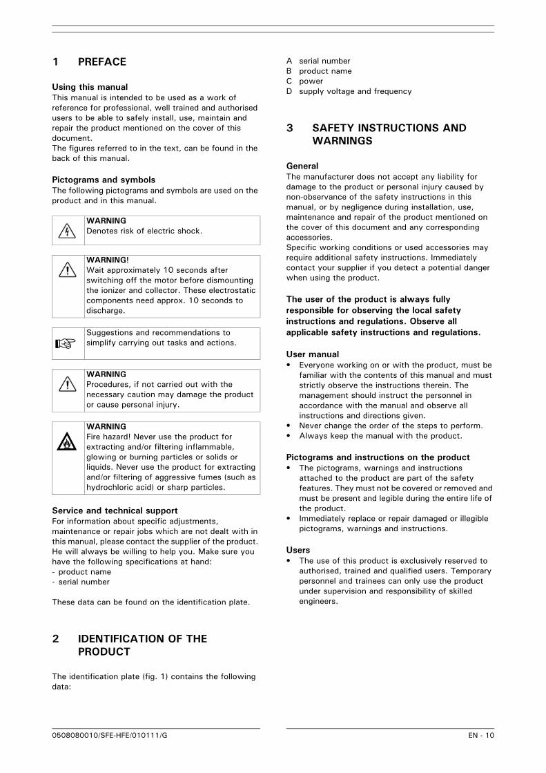
2 IDENTIFICATION OF THE PRODUCT
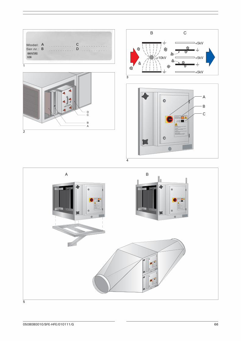
The identification plate (fig. 1) contains the following data:
A serial numberB product nameC powerD supply voltage and frequency
3 SAFETY INSTRUCTIONS AND WARNINGS
GeneralThe manufacturer does not accept any liability for damage to the product or personal injury caused by non-observance of the safety instructions in this manual, or by negligence during installation, use, maintenance and repair of the product mentioned on the cover of this document and any corresponding accessories. Specific working conditions or used accessories may require additional safety instructions. Immediately contact your supplier if you detect a potential danger when using the product.
The user of the product is always fully responsible for observing the local safety instructions and regulations. Observe all applicable safety instructions and regulations.
User manual• Everyone working on or with the product, must be
familiar with the contents of this manual and must strictly observe the instructions therein. The management should instruct the personnel in accordance with the manual and observe all instructions and directions given.
• Never change the order of the steps to perform.• Always keep the manual with the product.
Pictograms and instructions on the product• The pictograms, warnings and instructions
attached to the product are part of the safety features. They must not be covered or removed and must be present and legible during the entire life of the product.
• Immediately replace or repair damaged or illegible pictograms, warnings and instructions.
Users• The use of this product is exclusively reserved to
authorised, trained and qualified users. Temporary personnel and trainees can only use the product under supervision and responsibility of skilled engineers.
. WARNINGDenotes risk of electric shock.
. WARNING!Wait approximately 10 seconds after switching off the motor before dismounting the ionizer and collector. These electrostatic components need approx. 10 seconds to discharge.
. Suggestions and recommendations to simplify carrying out tasks and actions.
. WARNINGProcedures, if not carried out with the necessary caution may damage the product or cause personal injury.
j
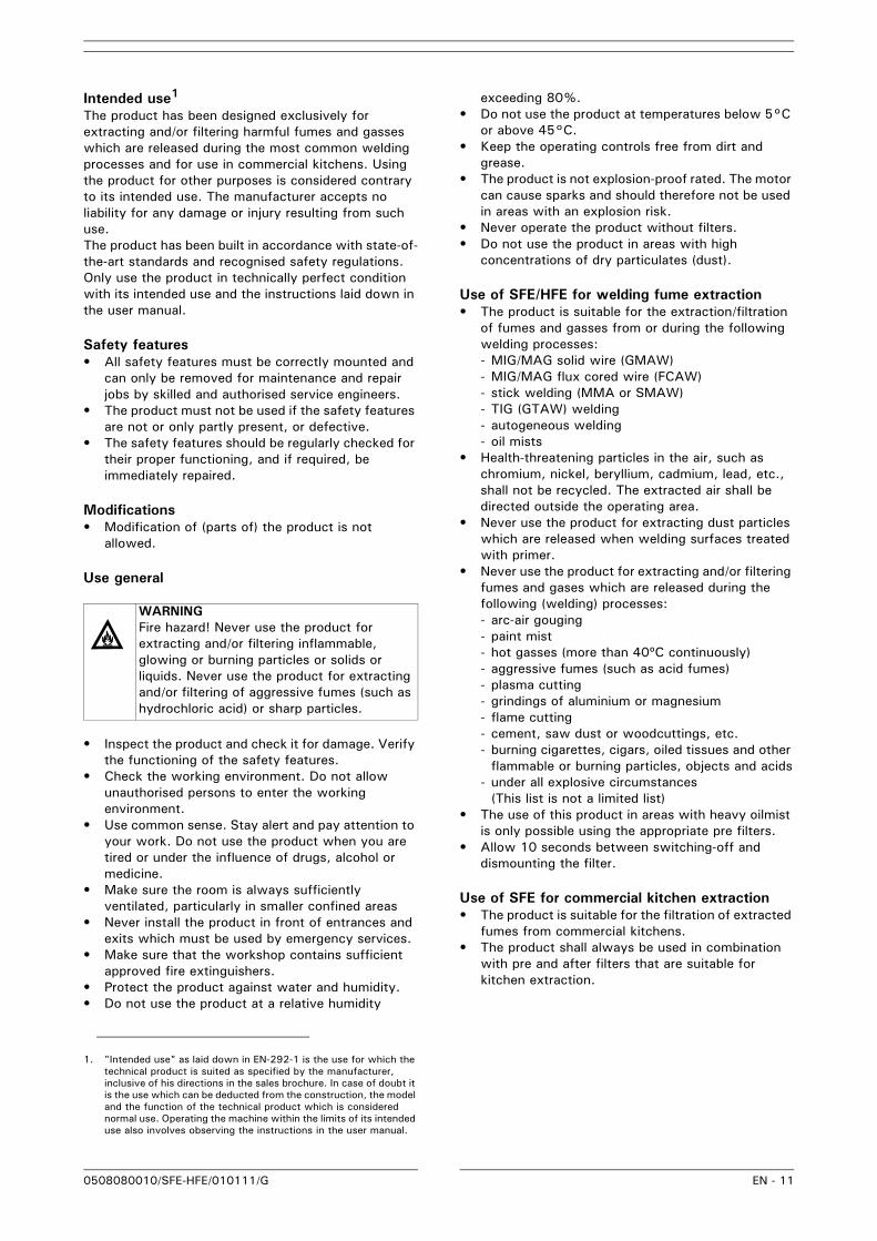
. WARNINGFire hazard! Never use the product for extracting and/or filtering inflammable, glowing or burning particles or solids or liquids. Never use the product for extracting and/or filtering of aggressive fumes (such as hydrochloric acid) or sharp particles.
0508080010/SFE-HFE/010111/G EN - 11
Intended use1
The product has been designed exclusively for extracting and/or filtering harmful fumes and gasses which are released during the most common welding processes and for use in commercial kitchens. Using the product for other purposes is considered contrary to its intended use. The manufacturer accepts no liability for any damage or injury resulting from such use. The product has been built in accordance with state-of-the-art standards and recognised safety regulations. Only use the product in technically perfect condition with its intended use and the instructions laid down in the user manual.
Safety features• All safety features must be correctly mounted and
can only be removed for maintenance and repair jobs by skilled and authorised service engineers.
• The product must not be used if the safety features are not or only partly present, or defective.
• The safety features should be regularly checked for their proper functioning, and if required, be immediately repaired.
Modifications• Modification of (parts of) the product is not
allowed.
Use general
• Inspect the product and check it for damage. Verify the functioning of the safety features.
• Check the working environment. Do not allow unauthorised persons to enter the working environment.
• Use common sense. Stay alert and pay attention to your work. Do not use the product when you are tired or under the influence of drugs, alcohol or medicine.
• Make sure the room is always sufficiently ventilated, particularly in smaller confined areas
• Never install the product in front of entrances and exits which must be used by emergency services.
• Make sure that the workshop contains sufficient approved fire extinguishers.
• Protect the product against water and humidity.• Do not use the product at a relative humidity
exceeding 80%.• Do not use the product at temperatures below 5°C
or above 45°C.• Keep the operating controls free from dirt and
grease.• The product is not explosion-proof rated. The motor
can cause sparks and should therefore not be used in areas with an explosion risk.
• Never operate the product without filters.• Do not use the product in areas with high
concentrations of dry particulates (dust).
Use of SFE/HFE for welding fume extraction• The product is suitable for the extraction/filtration
of fumes and gasses from or during the following welding processes:- MIG/MAG solid wire (GMAW)- MIG/MAG flux cored wire (FCAW)- stick welding (MMA or SMAW)- TIG (GTAW) welding- autogeneous welding- oil mists
• Health-threatening particles in the air, such as chromium, nickel, beryllium, cadmium, lead, etc., shall not be recycled. The extracted air shall be directed outside the operating area.
• Never use the product for extracting dust particles which are released when welding surfaces treated with primer.
• Never use the product for extracting and/or filtering fumes and gases which are released during the following (welding) processes:- arc-air gouging- paint mist- hot gasses (more than 40ºC continuously)- aggressive fumes (such as acid fumes)- plasma cutting- grindings of aluminium or magnesium- flame cutting- cement, saw dust or woodcuttings, etc.- burning cigarettes, cigars, oiled tissues and other
flammable or burning particles, objects and acids- under all explosive circumstances
(This list is not a limited list)• The use of this product in areas with heavy oilmist
is only possible using the appropriate pre filters. • Allow 10 seconds between switching-off and
dismounting the filter.
Use of SFE for commercial kitchen extraction• The product is suitable for the filtration of extracted
fumes from commercial kitchens.• The product shall always be used in combination
with pre and after filters that are suitable for kitchen extraction.
1. "Intended use" as laid down in EN-292-1 is the use for which the technical product is suited as specified by the manufacturer, inclusive of his directions in the sales brochure. In case of doubt it is the use which can be deducted from the construction, the model and the function of the technical product which is considered normal use. Operating the machine within the limits of its intended use also involves observing the instructions in the user manual.
j
. WARNINGFire hazard! Never use the product for extracting and/or filtering inflammable, glowing or burning particles or solids or liquids. Never use the product for extracting and/or filtering of aggressive fumes (such as hydrochloric acid) or sharp particles.
0508080010/SFE-HFE/010111/G EN - 12
Service, maintenance and repairs
• Observe the maintenance intervals given in this manual. Overdue maintenance can lead to high costs for repairs and revisions and can render the guarantee null and void.
• Always use tools, parts, materials, lubricants and service techniques that have been approved by the manufacturer. Never use worn tools and ensure that tools are not left behind in or on the product.
• Do not carry out any service, maintenance or repairs on the product before it has been protected against unintended starting.
• Safety features removed for servicing, maintenance or repair shall be re-installed immediately and checked for proper functioning.
• Regularly clean the inside of the housing.• Clean or replace the filters in time.
4 USED PRODUCTS AND THE ENVIRONMENT
ProductProducts which you would like to dispose of may still contain valuable substances and materials. Do not dispose of the product in the industrial waste, but ask your municipal sanitation department about the possibilities for reuse or environmentally safe processing of the material.
5 TECHNICAL SPECIFICATIONS
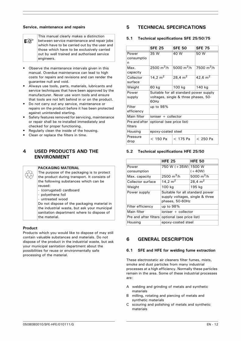
5.1 Technical specifications SFE 25/50/75
5.2 Technical specifications HFE 25/50
6 GENERAL DESCRIPTION
6.1 SFE and HFE for welding fume extraction
These electrostatic air cleaners filter fumes, mists, smoke and dust particles from many industrial processes at a high efficiency. Normally these particles remain in the area. Some of these industrial processes are:
A welding and grinding of metals and synthetic materials
B milling, rotating and piercing of metals and synthetic materials
C scouring and polishing of metals and synthetic materials
. This manual clearly makes a distinction between service maintenance and repair jobs which have to be carried out by the user and those which have to be exclusively carried out by well trained and authorised service engineers.
x
. PACKAGING MATERIALThe purpose of the packaging is to protect the product during transport. It consists of the following substances which can be reused:- (corrugated) cardboard- polyethene foil - untreated woodDo not dispose of the packaging material in the industrial waste, but ask your municipal sanitation department where to dispose of the material.
SFE 25 SFE 50 SFE 75Power consumption
35 W 40 W 50 W
Max. capacity
2500 m3/h 5000 m3/h 7500 m3/h
Collector surface
14,2 m2 28,4 m2 42,6 m2
Weight 60 kg 100 kg 140 kgPower supply
Suitable for all standard power supply voltages, single & three phases, 50-60Hz
Filter efficiency
up to 98%
Main filter ioniser + collectorPre and after filters
optional (see price list)
Housing epoxy-coated steelPressure drop < 150 Pa < 175 Pa < 250 Pa
HFE 25 HFE 50Power consumption
750 W (+35W) 1500 W (+40W)
Max. capacity 2500 m3/h 5000 m3/hCollector surface 14,2 m2 28,4 m2
Weight 100 kg 195 kgPower supply Suitable for all standard power
supply voltages, single & three phases, 50-60Hz
Filter efficiency up to 98%Main filter ioniser + collectorPre and after filters optional (see price list)Housing epoxy-coated steel
0508080010/SFE-HFE/010111/G EN - 13
D filling with powder and/or volatile materials
6.1.1 Modes of extraction of the polluted air• SFE: extraction arm or ducting system• HFE: extraction grid
6.2 SFE in kitchen extraction applications
This electrostatic air cleaner can remove, at a high efficiency, small grease particles that pass the grease filters. The SFE is designed to be installed in the extraction ducting of a commercial kitchen downstream of the extraction hood.
6.3 Oil drainer
It is possible to install an oil drainer in applications for welding of oil-treated steel, oil mist extraction or kitchen fume extraction in order to draw off superfluous liquids from the oil collector.
6.4 Operation
The extracted contaminated air passes the pre filter (fig. 2A) that takes out all larger particles. The pre filter also ensures a proper distribution of the airflow.
After that, the air passes the ioniser (fig. 2B and 3B). The contaminations in the air are electrically charged by the high voltage (+10kV). These will then be deposited on the earthed plates (fig. 2C and 3C) by the collector voltage (+5kV).
The after filter (fig. 2D) is the last filtration step and it also spreads the airflow.
There are a main switch (fig. 4A), a high-voltage indicator (fig. 4B) and a reset button (fig. 4C) on the control panel. Please contact your dealer if the high-voltage indicator is not working.Regularly check the functioning of the indicator when using the product, since it indicates that the electrostatic filter is properly charged.
When the product produces a crackling sound, then it could be that the collector and/or ioniser are too dirty and that both need to be cleaned. Switch off the product with the main switch (fig. 4A). Wait for at least 10 seconds prior to opening the door that contains the filtration section. Subsequently, clean the collector and ionisation sections using Plymovent EFC while adhering to the instructions on the EFC packaging. Check for touching collector lamellas. Consult your supplier if the lamellas are bent!
After closing the door of the housing switch on the unit by turning the main switch (fig. 4A) and press the reset button (fig. 4C).
The distinguishing characteristics of the modular mounting of the ionising and collector sections are the very high separation efficiency (up to 98% of particles larger than 0.1 µm), its low air resistance and the user-
friendliness while servicing the separate modules.
Repairs shall only be carried out by Plymovent or Plymovent authorised staff. Maintenance contracts are possible.
7 INSTALLATION
7.1 Installation SFE
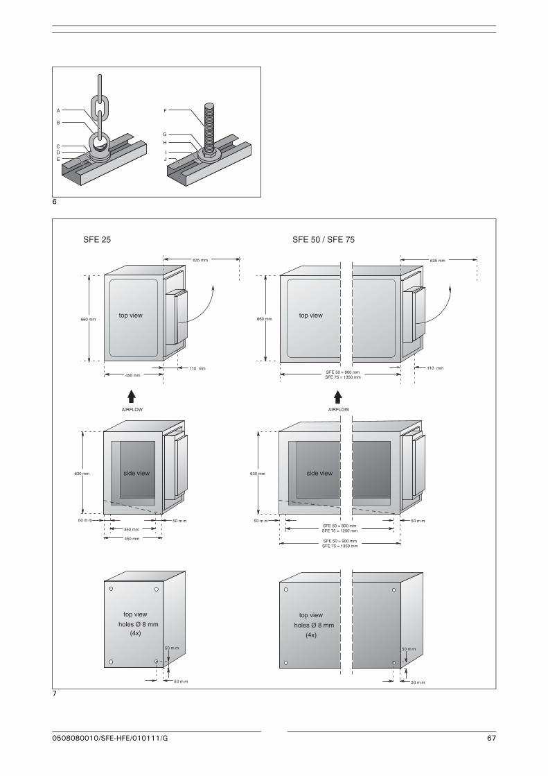
Check that the suspension construction is adequate prior to installing the product. Mount the SFE unit in the ducting system. It can be supported by a suspension bracket (fig 5A) as well as suspension by screw rods attached to the top of the SFE unit (fig. 5B). It is necessary to drill holes on the upper side for this purpose. It is also possible to place the unit on the ground providing sufficient space is allowed to use the drain plug.
Please consult the electrical diagram (separate leaflet, enclosed) when connecting the air cleaner to the mains. Use suitable rubber or neoprene cable with at least 4x1,5 mm2 wire area. Beware of possible differences in the mains power supply.
The air cleaner can be stacked to a maximum of 4 units; the perforations and protrusions on the housing can be used for this purpose.
7.2 Installation HFE
Check that the suspension construction is adequate prior to installing the product.Use the profiles (fig. 6E) when mounting the product and attach the connection rings (fig. 6B), the lock rings (fig. 6C) and the sliding nuts (fig. 6D) (all supplied with the product) to the profiles. Use a suitable suspension chain (fig. 6A) in this way of mounting. You can also use the profiles (fig. 6J) together with screw rods M8 of suitable length. These should be mounted as illustrated. The following parts are used in this case: screw rod M8 (fig. 6F), self-locking nut (fig. 6G), lock ring (fig. 6H) and sliding nut (fig. 6I).
Please consult the electrical diagram (separate leaflet, enclosed) when connecting the air cleaner to the mains. Use suitable rubber or neoprene cable with at least 4 x 1,5 mm2 wire area. Beware of possible differences in the mains power supply. The position of the contact bridges may need to be changed as well as the connections inside the motor compartment. When connecting, pay attention to the direction of rotation of the motor!
Ensure at all times that the setting of the thermal relay corresponds with the nominal current rating of the motor for the applicable power mains. This rating is given on the motor identification plate.
0508080010/SFE-HFE/010111/G EN - 14
8 DIMENSIONS
8.1 Dimensions SFE 25/50/75
See fig. 7.
8.2 Dimensions HFE 25/50
See fig. 8.
9 MAINTENANCE
If you observe the necessary caution and carry out the simple maintenance and cleaning described below at regular intervals, then any problems will mostly be detected and corrected before they result in a total breakdown of the product.The indicated maintenance intervals can vary depending on the specific working and local conditions.
It is therefore recommended that the product is thoroughly inspected annually in addition to the indicated periodic maintenance. Please contact your supplier for this purpose.
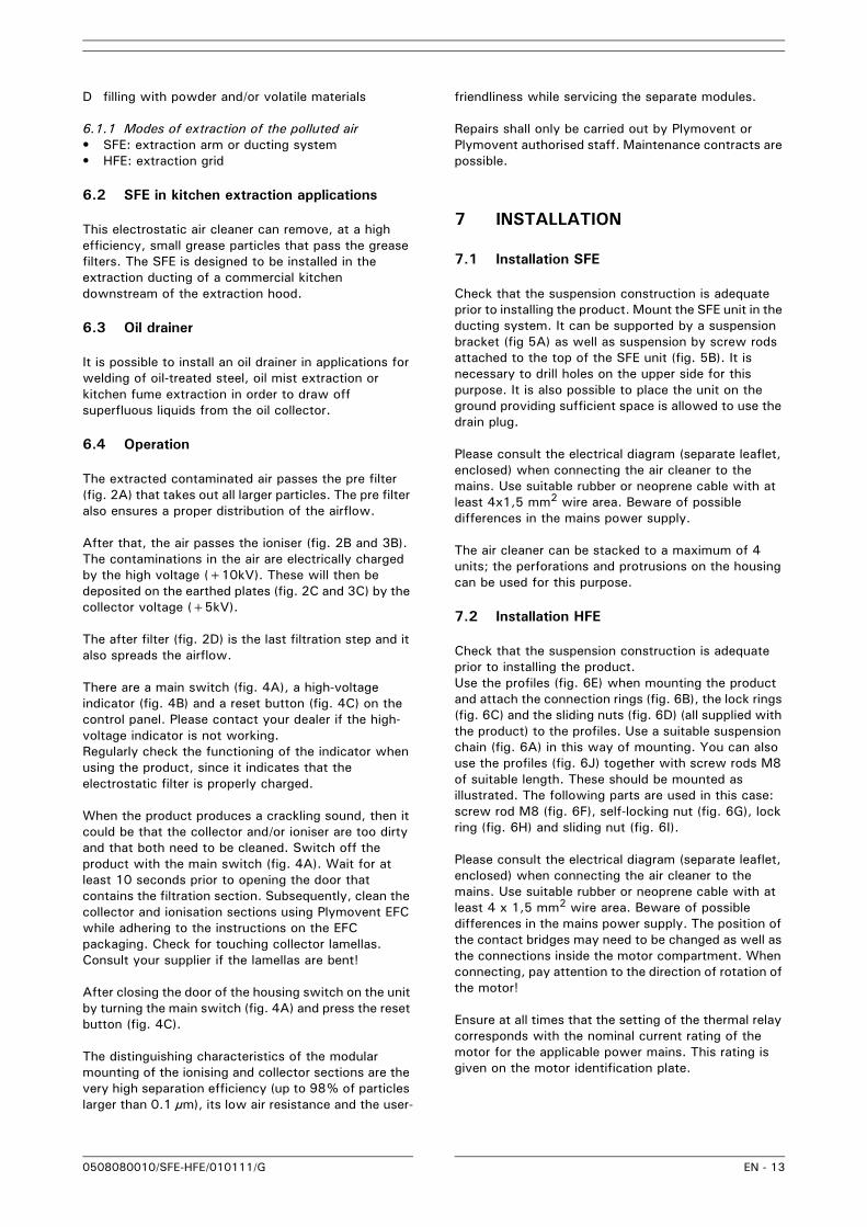
9.1 Periodic maintenance
The maintenance activities in the table below indicated by [1] can be carried out by the user; other activities are strictly reserved for qualified personnel.
9.2 Cleaning the pre filter, ioniser, collector and the after filter
Clean or replace the filters:• when damaged• when the ioniser and/or collector starts to make a
crackling sound (indicator starts blinking or stops being lit)
• when the extraction capacity becomes inadequate
It is a matter of experience to determine when the product needs to be cleaned, since the nature and the degree of pollution depend strongly on the particular situation, humidity, intensity of use, etc. Nevertheless, the filters should be cleaned regularly (every 2 weeks up to 2 months).
9.2.1 Removing the filters• Switch off the unit by turning the main switch (fig.
4A).• Loosen the star knobs and open the door.
• Remove the pre filter, ioniser, collector and the after filter (in this sequence).
9.2.2 Cleaning the pre and after filters• Clean the pre and after filters in hot water (approx.
60°C) added with a detergent for domestic use. This treatment can be repeated several times. Cleaning with a high-pressure spraying pistol is also possible.
• Allow for complete drying after cleaning.
9.2.3 Cleaning of the ioniser and collector• Clean the ioniser and collector in hot water (approx.
60°C) to which a 2% Plymovent EFC solution has been added. Cleaning using a high-pressure spraying pistol is also possible.
• Check the ioniser during washing for broken ionisation wires. These broken wires can simply be replaced.
• Check the collector during washing for bent
j
. WARNINGOverdue maintenance can cause fire.
. WARNINGAlways switch OFF the machine and remove the mains plug from the wall socket before carrying out the activities below. First read the maintenance regulations at the beginning of this manual.
Action Every 2 weeks to 2 months (depending on the degree of pollution)
Every 3 months
Every 6 months
Every 12 months
Clean the outside of the product with a mild detergent.
X[1]
Check the door sealing material. X[1]Clean the inside of the product and remove dust/grease from the filter compartment.
X[1]
Clean the pre filter, ioniser, collector and the after filter and check for damages; see section 9.2.
X[1]
. WARNINGPolluted filters often contain dust and dirt particles that could be a health hazard when inhaled. When replacing the filter, always wear a reliable and approved facemask.
. Plymovent EFC is a detergent specially developed for cleaning electrostatic filter cells. It is available from your supplier. Always follow the instructions on the packaging.
0508080010/SFE-HFE/010111/G EN - 15
lamellas. These can be carefully straightened with a screwdriver. Lamellas in contact with each other can cause short-circuiting.
• Allow for complete drying after cleaning.
9.2.4 Mounting the filters• Mount the filters, removed earlier, in reverse order.
10 TROUBLESHOOTING
If the machine does not function (correctly), consult the checklist below to see if you may remedy the error yourself (*). Should this not be possible consult a
qualified service engineer.
Always switch OFF the machine and disconnect the mains before carrying out any repairs. First read the repair instructions at the beginning of this manual.
10.1 SFE malfunctioning
10.2 HFE malfunctioning
. Note the correct position of the ioniser and collector. For this purpose, both filters have arrows indicating the direction of the airflow. Pay due attention to the position of the contact pin and contact spring.
. WARNINGFirst check whether the error is of a mechanical or electrical nature. The electric system can only be serviced or repaired by qualified and authorised service engineers.
. A number of problems in the checklist below can also be caused by defects in the connected equipment. This manual only deals with problems and solutions directly related to the machine itself.
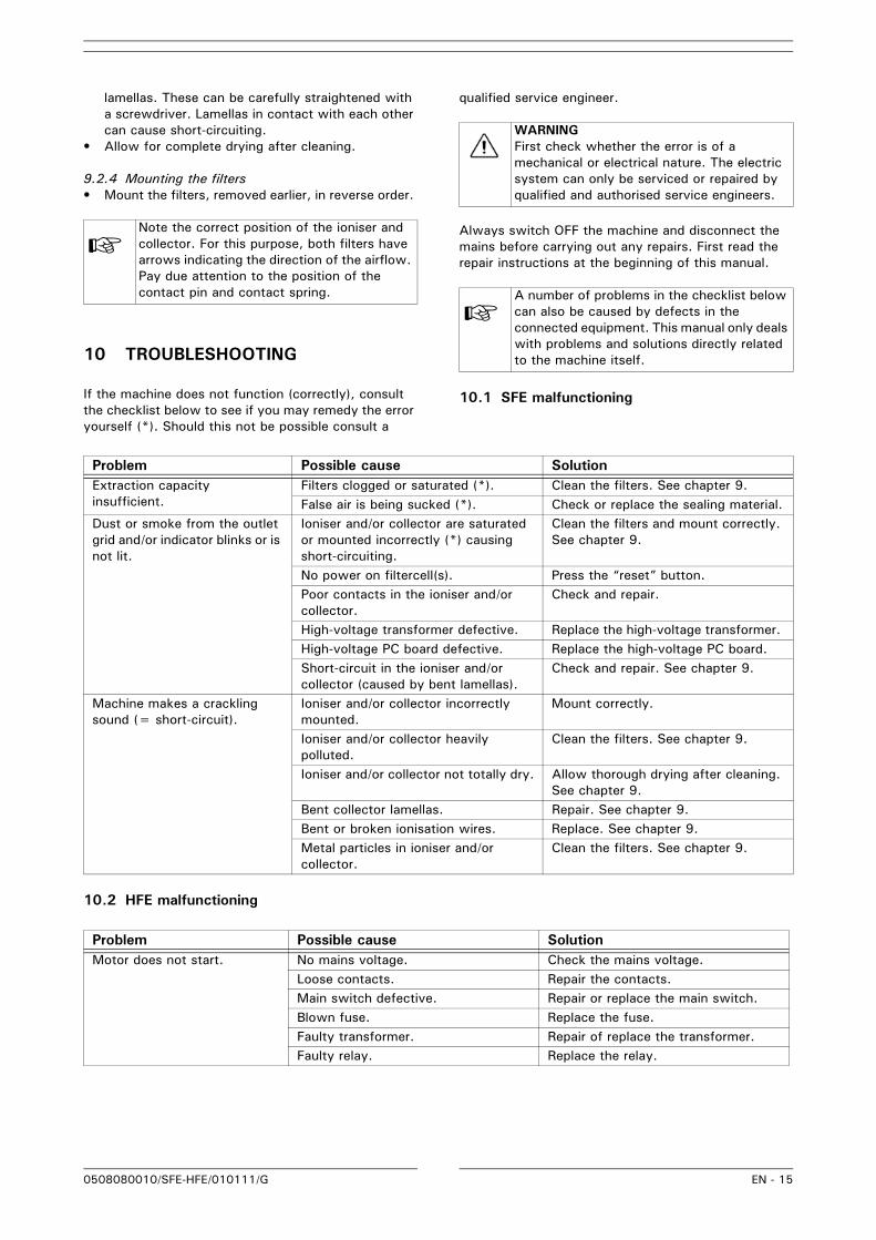
Problem Possible cause SolutionExtraction capacity insufficient.
Filters clogged or saturated (*). Clean the filters. See chapter 9.False air is being sucked (*). Check or replace the sealing material.
Dust or smoke from the outlet grid and/or indicator blinks or is not lit.
Ioniser and/or collector are saturated or mounted incorrectly (*) causing short-circuiting.
Clean the filters and mount correctly. See chapter 9.
No power on filtercell(s). Press the “reset” button.Poor contacts in the ioniser and/or collector.
Check and repair.
High-voltage transformer defective. Replace the high-voltage transformer. High-voltage PC board defective. Replace the high-voltage PC board. Short-circuit in the ioniser and/or collector (caused by bent lamellas).
Check and repair. See chapter 9.
Machine makes a crackling sound (= short-circuit).
Ioniser and/or collector incorrectly mounted.
Mount correctly.
Ioniser and/or collector heavily polluted.
Clean the filters. See chapter 9.
Ioniser and/or collector not totally dry. Allow thorough drying after cleaning. See chapter 9.
Bent collector lamellas. Repair. See chapter 9.Bent or broken ionisation wires. Replace. See chapter 9.Metal particles in ioniser and/or collector.
Clean the filters. See chapter 9.
Problem Possible cause SolutionMotor does not start. No mains voltage. Check the mains voltage.
Loose contacts. Repair the contacts. Main switch defective. Repair or replace the main switch.Blown fuse. Replace the fuse.Faulty transformer. Repair of replace the transformer.Faulty relay. Replace the relay.
0508080010/SFE-HFE/010111/G EN - 16
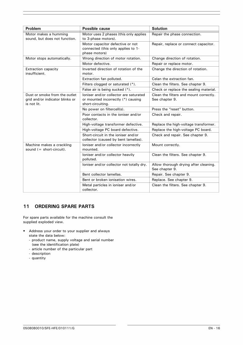
11 ORDERING SPARE PARTS
For spare parts available for the machine consult the supplied exploded view.
• Address your order to your supplier and always state the data below:- product name, supply voltage and serial number
(see the identification plate)- article number of the particular part- description- quantity
Motor makes a humming sound, but does not function.
Motor uses 2 phases (this only applies to 3-phase motors).
Repair the phase connection.
Motor capacitor defective or not connected (this only applies to 1-phase motors)
Repair, replace or connect capacitor.
Motor stops automatically. Wrong direction of motor rotation. Change direction of rotation.Motor defective. Repair or replace motor.
Extraction capacity insufficient.
Inverted direction of rotation of the motor.
Change the direction of rotation.
Extraction fan polluted. Celan the extraction fan. Filters clogged or saturated (*). Clean the filters. See chapter 9.False air is being sucked (*). Check or replace the sealing material.
Dust or smoke from the outlet grid and/or indicator blinks or is not lit.
Ioniser and/or collector are saturated or mounted incorrectly (*) causing short-circuiting.
Clean the filters and mount correctly. See chapter 9.
No power on filtercell(s). Press the “reset” button.Poor contacts in the ioniser and/or collector.
Check and repair.
High-voltage transformer defective. Replace the high-voltage transformer. High-voltage PC board defective. Replace the high-voltage PC board. Short-circuit in the ioniser and/or collector (caused by bent lamellas).
Check and repair. See chapter 9.
Machine makes a crackling sound (= short-circuit).
Ioniser and/or collector incorrectly mounted.
Mount correctly.
Ioniser and/or collector heavily polluted.
Clean the filters. See chapter 9.
Ioniser and/or collector not totally dry. Allow thorough drying after cleaning. See chapter 9.
Bent collector lamellas. Repair. See chapter 9.Bent or broken ionisation wires. Replace. See chapter 9.Metal particles in ioniser and/or collector.
Clean the filters. See chapter 9.
Problem Possible cause Solution
0508080010/SFE-HFE/010111/G EN - 17
CE DECLARATIONS
SFE 25/50/75:
MANUFACTURER'S DECLARATION(Directive 98/37/EEC, Annex II, sub B)
Plymovent, Alkmaar, the Netherlands herewith declares that the following machinery components are intended to be assembled with other machinery components to constitute machinery, which shall not be put into service until the entire installation has been declared in conformity with the provisions of the EC Council Directive and/or the local Directives on Machinery and the instructions of the manual of the machinery components: SFE 25/50/75.
Applied harmonized standards, in particular:- EN 292-1- EN 292-2- EN 294- EN 349- EN 60335-1- EN 60335-2- EN 55014- EN 61000
Remark: Taking the machine in question into operation is only allowed after determination that the entire installation, of which the machinery component(s) in question form(s) part, is in compliance with the Directive 98/37/EEC and with the local Directives. These Directives specially guarantee the user's safety by means of, among other things, electrical emergency stops, fuses, earth wires and touch prevention for running and charged components. The installation manufacturer is responsible for taking the entire system into operation.
Alkmaar, 1st March 2005
Ing. C.J.M. Knijn
HFE 25/50:
EC-DECLARATION OF CONFORMITY FOR MACHINERY(Directive 98/37/EEC, Annex II, sub A)
Plymovent, Alkmaar, the Netherlands
herewith declares that the following products: HFE 25/50
are in compliance with the Directives:• 93/68/EEC• EMC 89/336/EEC• 73/23/EEC
the following harmonized standards have been applied:• EN 60335-1• EN 60335-2• EN 292-1• EN 292-2• EN 294• EN 55014• EN 61000
Alkmaar, 1st March 2005
Ing. C.J.M. Knijn
0508080010/SFE-HFE/010111/G 66
ILLUSTRATIONS
1
2
3
4
5
BA
DC
DC
BA
AIR FLOW
+10kV +5kV
+5kV
+5kV
B C
A
B
C
BA
0508080010/SFE-HFE/010111/G 67
6
7
A
B
C
ED
F
G
JI
H
AIRFLOW
top view
top view
holes Ø 8 mm(4x)
side view
660 mm
450 mm
350 mm
630 mm
50 m m
110 mm
635 mm
660 mm
110 mm
590 mm
450 mm
50 m m
630 mm
50 m50 m m m
50 m m 50 m m
50 m m50 m m
AIRFLOW
110 mm
635 mm
50 m m
50 m m
50 m m
top view
holes Ø 8 mm
(4x)
side view
top view
SFE 50 = 900 mmSFE 75 = 1350 mm
SFE 50 = 900 mmSFE 75 = 1350 mm
SFE 50 = 800 mmSFE 75 = 1250 mm
SFE 25 SFE 50 / SFE 75
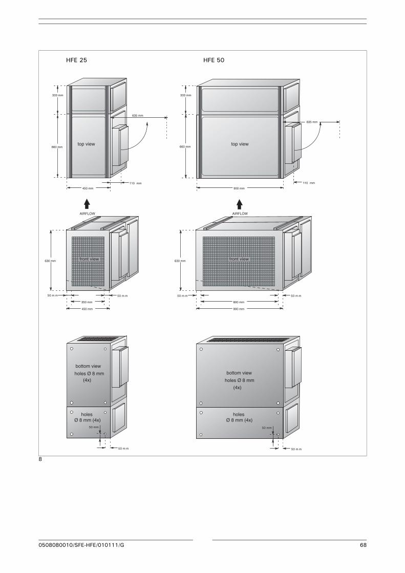
0508080010/SFE-HFE/010111/G 68
8
AIRFLOW AIRFLOW
top view
bottom view
holes Ø 8 mm(4x)
holes Ø 8 mm (4x)
holes Ø 8 mm (4x)
bottom view
holes Ø 8 mm
(4x)
side viewtop view
top view
front view front view
660 mm
333 mm
450 mm
350 mm
630 mm
50 m m
110 mm
635 mm
900 mm
660 mm
110 mm
635 mm
450 mm
50 m m
900 mm
800 mm
630 mm
50 m50 m m m
50 m m
50 mm
50 m m
50 mm
333 mm
HFE 25 HFE 50

www.plymovent.com
0508080010/010111/G SFE-HFE