RFE-1-YE_-ECE-IDO-005-REVA comments CPI Cálculo del sistema de protección contra el rayo.pdf
46
PLANTA DE RESERVA FRÍA DE GENERACIÓN DE ETEN S.A PROYECTO PROJECT RESERVA FRÍA ETEN CONTRATISTA CONTRACTOR TÍTULO TITLE CÁLCULO DEL SISTEMA DE PROTECCIÓN CONTRA EL RAYO Nº DE DOCUMENTO PROYECTO PROJECT DOCUMENT Nº RFE-1-YE__-ECE-IDO-005 REV A EDITADO PARA ISSUED FOR Para diseño FECHA DATE 20/05/2014 XGR PRV JSA REALIZADO DONE BY REVISADO CHECKED BY APROBADO APPROVED BY ESTE DOCUMENTO CONTIENE INFORMACIÓN PROPIETARIA Y NO PUEDE SER DUPLICADO, PROCESADO O CEDIDO A TERCEROS PARA UN USO DISTINTO AL DE ESTE PROYECTO Y EL OBJETO PARA EL QUE HA SIDO PREVISTO SIN LA AUTORIZACIÓN ESCRITA DE COBRA. THIS DOCUMENT CONTAINS PROPIETARY INFORMATION AND CAN NOT BE DUPLICATED, PROCESSED OR DISCLOSED TO THIRD PARTIES FOR ANY USE OTHER THAN THIS PROJECT AND THE PURPOSE FOR WHICH IT IS INTENDED FOR WITHOUT THE WRITTEN CONSENT OF COBRA.
Transcript of RFE-1-YE_-ECE-IDO-005-REVA comments CPI Cálculo del sistema de protección contra el rayo.pdf
PLANTA DE RESERVA FRÍA DE GENERACIÓN DE ETEN S.A
PROYECTO PROJECT
RESERVA FRÍA ETEN CONTRATISTA CONTRACTOR
TÍTULO TITLE
CÁLCULO DEL SISTEMA DE PROTECCIÓN CONTRA EL RAYO
Nº DE DOCUMENTO PROYECTO PROJECT DOCUMENT Nº
RFE-1-YE__-ECE-IDO-005
REV A EDITADO PARA ISSUED FOR
Para diseño FECHA DATE
20/05/2014
XGR
PRV
JSA
REALIZADO DONE BY
REVISADO CHECKED BY
APROBADO APPROVED BY
ESTE DOCUMENTO CONTIENE INFORMACIÓN PROPIETARIA Y NO PUEDE SER DUPLICADO, PROCESADO O CEDIDO A TERCEROS PARA UN USO DISTINTO AL DE ESTE PROYECTO Y EL OBJETO PARA EL QUE HA SIDO PREVISTO SIN LA AUTORIZACIÓN ESCRITA DE COBRA.
THIS DOCUMENT CONTAINS PROPIETARY INFORMATION AND CAN NOT BE DUPLICATED, PROCESSED OR DISCLOSED TO THIRD PARTIES FOR ANY USE OTHER THAN THIS PROJECT AND THE PURPOSE FOR WHICH IT IS INTENDED FOR WITHOUT THE WRITTEN CONSENT OF COBRA.
pbona
Cuadro de texto
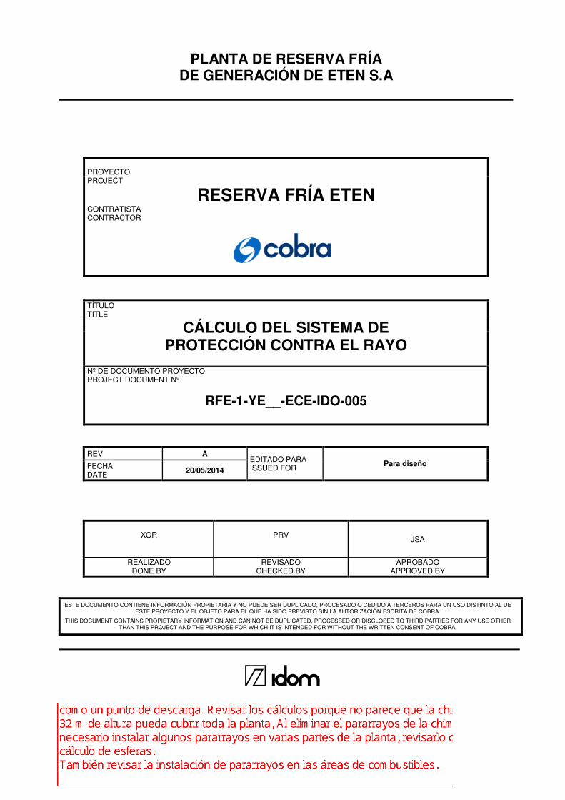
La chimenea será metálica, no se instalará pararrayos en la parte superior y se tomará como un punto de descarga. Revisar los cálculos porque no parece que la chimenea con 32 m de altura pueda cubrir toda la planta, Al eliminar el pararrayos de la chimenea, será necesario instalar algunos pararrayos en varias partes de la planta, revisarlo con el cálculo de esferas. También revisar la instalación de pararrayos en las áreas de combustibles.
Cálculo del sistema de
protección contra el rayo
RFE-1-YE_-ECE-IDO-005
Rev.A Pág/Page 2 de/of 17
Este documento contiene información propiedad de Cobra y está sujeto a las restricciones detalladas en la página de portada.
La única copia controlada de este documento es la incluida en la intranet de Cobra.
This document contains proprietary information of Cobra and is subject to the restrictions set forth on the title page.
The only controlled copy of the document is located on the Cobra intranet.
CONTROL DE MODIFICACIONES/CHANGE LOG
Revisión
Revision
Fecha
Date
Modificaciones
Modifications
A 20/05/2014
EDICIÓN INICIAL
Cálculo del sistema de
protección contra el rayo
RFE-1-YE_-ECE-IDO-005
Rev.A Pág/Page 3 de/of 17
Este documento contiene información propiedad de Cobra y está sujeto a las restricciones detalladas en la página de portada.
La única copia controlada de este documento es la incluida en la intranet de Cobra.
This document contains proprietary information of Cobra and is subject to the restrictions set forth on the title page.
The only controlled copy of the document is located on the Cobra intranet.
ÍNDICE
1. OBJETO ............................................................................................................................. 4
2. NORMATIVA Y DOCUMENTACIÓN DE REFERENCIA ..................................................... 5
3. DATOS DE PARTIDA ......................................................................................................... 6
3.1. CONDICIONES DE LA IMPLANTACIÓN ................................................................... 6
3.2. CONDICIONES AMBIENTALES ................................................................................ 6
4. DIMENSIONAMIENTO DEL SISTEMA DE PROTECIÓN CONTRA EL RAYO................... 8
4.1. ANÁLISIS DEL RIESGO ............................................................................................ 8
4.2. CÁLCULO DEL NIVEL DE PROTECCIÓN ................................................................. 9
4.3. HIPÓTESIS ................................................................................................................ 9
4.4. RESULTADOS ......................................................................................................... 10
5. DESCRIPCIÓN DEL SISTEMA DE PROTECIÓN CONTRA EL RAYO ............................ 11
5.1. VOLUMEN PROTEGIDO ......................................................................................... 11
5.2. CONDUCTORES DE BAJADA Y PUESTA A TIERRA ............................................. 12
6. CONCLUSIONES .............................................................................................................. 13
7. ANEXOS ........................................................................................................................... 14

Cálculo del sistema de
protección contra el rayo
RFE-1-YE_-ECE-IDO-005
Rev.A Pág/Page 4 de/of 17
Este documento contiene información propiedad de Cobra y está sujeto a las restricciones detalladas en la página de portada.
La única copia controlada de este documento es la incluida en la intranet de Cobra.
This document contains proprietary information of Cobra and is subject to the restrictions set forth on the title page.
The only controlled copy of the document is located on the Cobra intranet.
1. OBJETO
El objeto del presente documento es recoger el dimensionamiento del sistema de protección
contra el rayo que se instalará en la Planta de Reserva Fría de Eten (Perú).
Para la realización del presente estudio se empleará, como herramienta de cálculo, la versión del
software “IEC Risk Assessment Calculator version 1.0.3.”.

Cálculo del sistema de
protección contra el rayo
RFE-1-YE_-ECE-IDO-005
Rev.A Pág/Page 5 de/of 17
Este documento contiene información propiedad de Cobra y está sujeto a las restricciones detalladas en la página de portada.
La única copia controlada de este documento es la incluida en la intranet de Cobra.
This document contains proprietary information of Cobra and is subject to the restrictions set forth on the title page.
The only controlled copy of the document is located on the Cobra intranet.
2. NORMATIVA Y DOCUMENTACIÓN DE REFERENCIA
Para el diseño del sistema de protección contra el rayo se tendrán en cuenta las siguientes
normativas y documentos de referencia:
• IEC 62305 Protección contra el rayo.
• UNE-EN 21186 Protección de estructuras, edificaciones y zonas abiertas
mediante pararrayos con dispositivo de cebado.
• RFE-1-YE_-EDA-IDO-006 “Pararrayos. Implantación y áreas de protección”
• RFE-1-YE_-EIP-IDO-004 “Especificación Técnica. Protección contra el rayo”.
• RFE-1-YE_-ERD-IDO-001 “Criterios de diseño eléctrico”
Cálculo del sistema de
protección contra el rayo
RFE-1-YE_-ECE-IDO-005
Rev.A Pág/Page 6 de/of 17
Este documento contiene información propiedad de Cobra y está sujeto a las restricciones detalladas en la página de portada.
La única copia controlada de este documento es la incluida en la intranet de Cobra.
This document contains proprietary information of Cobra and is subject to the restrictions set forth on the title page.
The only controlled copy of the document is located on the Cobra intranet.
3. DATOS DE PARTIDA
A continuación se indican los datos de partida utilizados para el cálculo del sistema de protección
contra el rayo:
3.1. CONDICIONES DE LA IMPLANTACIÓN
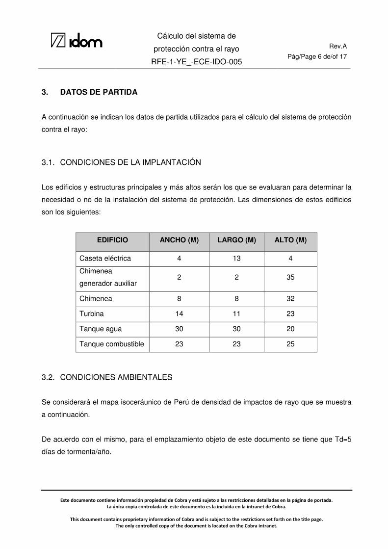
Los edificios y estructuras principales y más altos serán los que se evaluaran para determinar la
necesidad o no de la instalación del sistema de protección. Las dimensiones de estos edificios
son los siguientes:
EDIFICIO ANCHO (M) LARGO (M) ALTO (M)
Caseta eléctrica 4 13 4
Chimenea
generador auxiliar 2 2 35
Chimenea 8 8 32
Turbina 14 11 23
Tanque agua 30 30 20
Tanque combustible 23 23 25
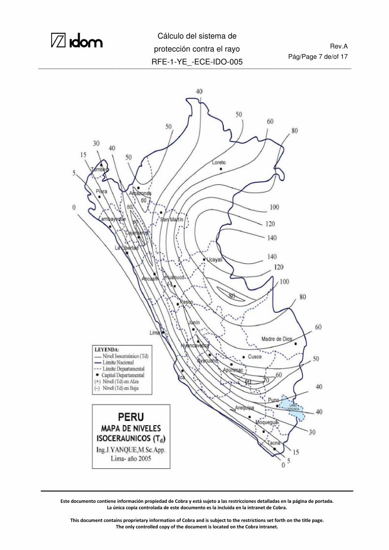
3.2. CONDICIONES AMBIENTALES
Se considerará el mapa isoceráunico de Perú de densidad de impactos de rayo que se muestra
a continuación.
De acuerdo con el mismo, para el emplazamiento objeto de este documento se tiene que Td=5
días de tormenta/año.
Cálculo del sistema de
protección contra el rayo
RFE-1-YE_-ECE-IDO-005
Rev.A Pág/Page 7 de/of 17
Este documento contiene información propiedad de Cobra y está sujeto a las restricciones detalladas en la página de portada.
La única copia controlada de este documento es la incluida en la intranet de Cobra.
This document contains proprietary information of Cobra and is subject to the restrictions set forth on the title page.
The only controlled copy of the document is located on the Cobra intranet.

Cálculo del sistema de
protección contra el rayo
RFE-1-YE_-ECE-IDO-005
Rev.A Pág/Page 8 de/of 17
Este documento contiene información propiedad de Cobra y está sujeto a las restricciones detalladas en la página de portada.
La única copia controlada de este documento es la incluida en la intranet de Cobra.
This document contains proprietary information of Cobra and is subject to the restrictions set forth on the title page.
The only controlled copy of the document is located on the Cobra intranet.
4. DIMENSIONAMIENTO DEL SISTEMA DE PROTECIÓN CONTRA EL RAYO
4.1. ANÁLISIS DEL RIESGO
Para determinar la necesidad o no de que un edificio o estructura disponga de un sistema de
protección, se debe analizar la posibilidad de que un rayo impacte en dicha estructura y los
daños que pueda causar.
Se definirán los niveles de protección siguiendo el procedimiento descrito en la norma IEC
62305-2.
Se deberán tener en cuenta los siguientes tipos de riesgo, en función de los tipos de pérdidas
definidos en la IEC 62305-2:
• R1: riesgo de pérdida de vida humana
• R2: riesgo de pérdida de servicio al público
• R3: riesgo de pérdida de patrimonio cultural
• R4: riesgo de pérdida de valor económico
Será necesaria la protección contra el rayo si el riesgo R (R1 a R4) es superior al riesgo tolerable
RT. En este caso deben aplicarse medidas de protección con el fin de reducir el riesgo R (R1 a
R4) al valor de riesgo tolerable RT.
Los valores representativos de riesgo tolerable RT están indicadas en la tabla 7 de la norma IEC
punto 5.4, si bien se adjunta a continuación:
Cálculo del sistema de
protección contra el rayo
RFE-1-YE_-ECE-IDO-005
Rev.A Pág/Page 9 de/of 17
Este documento contiene información propiedad de Cobra y está sujeto a las restricciones detalladas en la página de portada.
La única copia controlada de este documento es la incluida en la intranet de Cobra.
This document contains proprietary information of Cobra and is subject to the restrictions set forth on the title page.
The only controlled copy of the document is located on the Cobra intranet.
4.2. CÁLCULO DEL NIVEL DE PROTECCIÓN
Se procederá a calcular el riesgo mediante el programa de cálculo “IEC Risk Assessment
Calculator” que es un programa informático basado en los métodos de cálculo de la norma IEC
62305-2.
La forma de cálculo de los diferentes riesgos se adjunta en el Anexo 1. Con los datos iniciales
para cada edificio, se calculan los diferentes riesgos y se comparan con el riego tolerable para
verificar si la solución escogida protege o no el edificio. Los diferentes sub-riesgos para cada
edificio se adjuntan en el Anexo 2.
Los diferentes parámetros de cada edificio se incluyen en cada hoja de cálculo en el Anexo 3,
incluyendo el tipo de protección especificada.
4.3. HIPÓTESIS
Con el fin de diseñar el sistema de protección contra rayos se emplearán los siguientes criterios:
• Se consideran componentes naturales de un sistema de captura las estructuras metálicas
con un espesor superior a 4mm, según el apartado 5.2.5 de la norma IEC 62305-3. Se
incluyen en este punto los tanques y las chimeneas instalados en la planta.

Cálculo del sistema de
protección contra el rayo
RFE-1-YE_-ECE-IDO-005
Rev.A Pág/Page 10 de/of 17
Este documento contiene información propiedad de Cobra y está sujeto a las restricciones detalladas en la página de portada.
La única copia controlada de este documento es la incluida en la intranet de Cobra.
This document contains proprietary information of Cobra and is subject to the restrictions set forth on the title page.
The only controlled copy of the document is located on the Cobra intranet.
4.4. RESULTADOS
Los diferentes edificios tendrán las siguientes medidas de protección:
Edificio Clase de SPCR Protección contra
incendios
Protección contra
sobretensiones
Caseta eléctrica Sin SPCR Sistemas automáticos
Sólo en entrada de
servicios
Chimenea generador
auxiliar Sin SPCR Sin medidas Sin protección
Chimenea Sin SPCR Sin medidas Sin protección
Turbina Clase IV Sistemas automáticos
Sólo en entrada de
servicios
Tanque agua Sin SPCR Sin medidas Sin protección
Tanque combustible Clase IV Sistemas automáticos
Sólo en entrada de
servicios
Según los criterios descritos anteriormente, se instalará un pararrayos para la protección de la
turbina, y se considera que los tanques de combustible están intrínsecamente protegidos debido
a que se consideran componentes naturales del sistema de protección.
Cálculo del sistema de
protección contra el rayo
RFE-1-YE_-ECE-IDO-005
Rev.A Pág/Page 11 de/of 17
Este documento contiene información propiedad de Cobra y está sujeto a las restricciones detalladas en la página de portada.
La única copia controlada de este documento es la incluida en la intranet de Cobra.
This document contains proprietary information of Cobra and is subject to the restrictions set forth on the title page.
The only controlled copy of the document is located on the Cobra intranet.
5. DESCRIPCIÓN DEL SISTEMA DE PROTECIÓN CONTRA EL RAYO
5.1. VOLUMEN PROTEGIDO
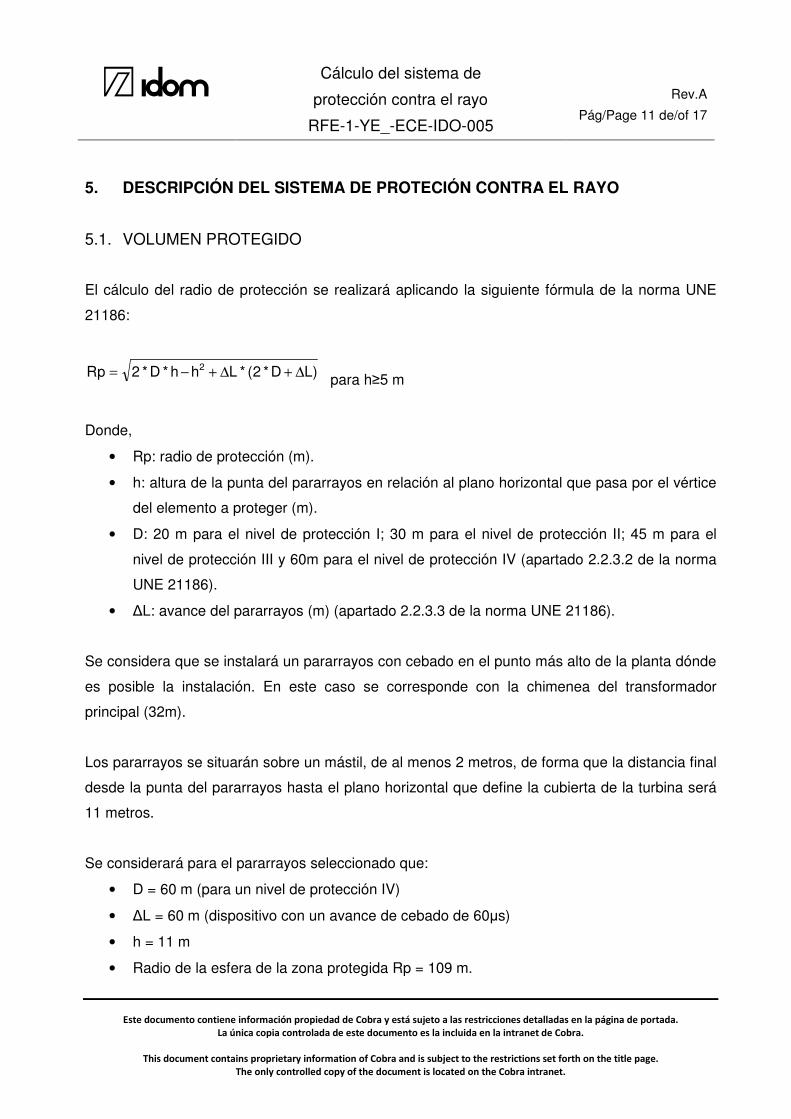
El cálculo del radio de protección se realizará aplicando la siguiente fórmula de la norma UNE
21186:
)LD*2(*Lhh*D*2pR 2∆+∆+−= para h≥5 m
Donde,
• Rp: radio de protección (m).
• h: altura de la punta del pararrayos en relación al plano horizontal que pasa por el vértice
del elemento a proteger (m).
• D: 20 m para el nivel de protección I; 30 m para el nivel de protección II; 45 m para el
nivel de protección III y 60m para el nivel de protección IV (apartado 2.2.3.2 de la norma
UNE 21186).
• ∆L: avance del pararrayos (m) (apartado 2.2.3.3 de la norma UNE 21186).
Se considera que se instalará un pararrayos con cebado en el punto más alto de la planta dónde
es posible la instalación. En este caso se corresponde con la chimenea del transformador
principal (32m).
Los pararrayos se situarán sobre un mástil, de al menos 2 metros, de forma que la distancia final
desde la punta del pararrayos hasta el plano horizontal que define la cubierta de la turbina será
11 metros.
Se considerará para el pararrayos seleccionado que:
• D = 60 m (para un nivel de protección IV)
• ∆L = 60 m (dispositivo con un avance de cebado de 60µs)
• h = 11 m
• Radio de la esfera de la zona protegida Rp = 109 m.
Cálculo del sistema de
protección contra el rayo
RFE-1-YE_-ECE-IDO-005
Rev.A Pág/Page 12 de/of 17
Este documento contiene información propiedad de Cobra y está sujeto a las restricciones detalladas en la página de portada.
La única copia controlada de este documento es la incluida en la intranet de Cobra.
This document contains proprietary information of Cobra and is subject to the restrictions set forth on the title page.
The only controlled copy of the document is located on the Cobra intranet.
5.2. CONDUCTORES DE BAJADA Y PUESTA A TIERRA
Los derivadores conducirán la corriente de descarga atmosférica desde el dispositivo captador a
la toma de tierra, sin calentamientos y sin elevaciones de potenciales peligrosos. Esta toma de
tierra estará formada por un triángulo de picas y un puente de pruebas, mediante el cual se unirá
a la red general de tierra de la planta.
De acuerdo a lo indicado en el punto 2.3.2 de la 1ª modificación de la norma UNE 21186 se
instalará dos bajantes por cada punta de cebado. Los conductores de bajada podrán ser iguales
o mayores a 50 mm2.

Cálculo del sistema de
protección contra el rayo
RFE-1-YE_-ECE-IDO-005
Rev.A Pág/Page 13 de/of 17
Este documento contiene información propiedad de Cobra y está sujeto a las restricciones detalladas en la página de portada.
La única copia controlada de este documento es la incluida en la intranet de Cobra.
This document contains proprietary information of Cobra and is subject to the restrictions set forth on the title page.
The only controlled copy of the document is located on the Cobra intranet.
6. CONCLUSIONES
Para la protección contra descargas atmosféricas de la Planta de Reserva Fría de Eten, de
acuerdo a los niveles de protección establecidos en este documento, se debe instalar un
pararrayos con dispositivo de cebado, con un avance de cebado de 60µs.
El pararrayos se instalará en un mástil 2 metros sobre la chimenea del generador principal, de
forma que se encuentre a 34 metros de altura sobre la cota de pavimento acabado.
El plano “RFE-1-YE_-EDA-IDO-006 Pararrayos. Implantación y áreas de protección” define la
ubicación, zona protegida y detalles de instalación del pararrayos previsto.

Cálculo del sistema de
protección contra el rayo
RFE-1-YE_-ECE-IDO-005
Rev.A Pág/Page 14 de/of 17
Este documento contiene información propiedad de Cobra y está sujeto a las restricciones detalladas en la página de portada.
La única copia controlada de este documento es la incluida en la intranet de Cobra.
This document contains proprietary information of Cobra and is subject to the restrictions set forth on the title page.
The only controlled copy of the document is located on the Cobra intranet.
7. ANEXOS
Anexo 1: Instrucciones del software IEC Risk Assessment Calculator. Anexo 2: Riesgo de los diferentes edificios. Anexo 3: Cálculos.

Cálculo del sistema de
protección contra el rayo
RFE-1-YE_-ECE-IDO-005
Rev.A Pág/Page 15 de/of 17
Este documento contiene información propiedad de Cobra y está sujeto a las restricciones detalladas en la página de portada.
La única copia controlada de este documento es la incluida en la intranet de Cobra.
This document contains proprietary information of Cobra and is subject to the restrictions set forth on the title page.
The only controlled copy of the document is located on the Cobra intranet.
ANEXO 1:
INSTRUCCIONES DEL SOFTWARE IEC RISK
ASSESSMENT CALCULATOR
Page 1
DEVELOPMENT OF A RISK ASSESSMENT CALCULATOR BASED ON A SIMPLIFIED FORM OF THE IEC 62305-2
STANDARD ON LIGHTNING PROTECTION
A. J. Surtees
[email protected] ERICO Inc.,
USA
A. Gillespie [email protected]
Powerlink, Australia
A. Kern [email protected] Aachen University of
Applied Sciences Department Juelich
Germany
A. Rousseau [email protected]
APS France
Abstract: IEC Technical Committee 81 is currently creating the new IEC 62305 series of standards on Lightning Protection. Working Group 9 has been tasked with developing Part 2 of this five part series. IEC 62305 - part 2 deals with the assessment and management of risk to structures and personnel. This document is currently in its CDV (Committee Draft for Voting) stage and has been circulated to National Committees for comment.
This paper details the development of the Simplified IEC Risk Assessment Calculator software tool as described in Informative Annex J of IEC62305-2 Ed.1/CDV 2. This tool is based on calculations and methods detailed in the standard and is intended as a simplified implementation of the more rigorous treatment of risk management found in the written document. The tool is designed to be relatively intuitive for users who wish to obtain an initial assessment of risk sensitivity, but should not be considered a substitute to a full understanding of the methods provided in the standard when dealing with more complicated structures or those where greater risks to personal or system operation are involved.
Keywords: Risk, Risk Management, Risk Assessment, Lightning Risk, Lightning Protection.
1. INTRODUCTION The simplified IEC Risk Assessment Calculator is intended to function as a companion, and not alternative, to the written standard. Its intended purpose (and limitations) may be summarised as follows:
To promote the risk management methods detailed in the standard in a s implified and user-friendly format, thereby gaining wider adoption within the lightning protection community by lightning protection installers and general contractors.
To enable more general users of the IEC 62305-2 standard to conduct calculations on typical structures without
requiring that they first have an in-depth knowledge of the details and methodologies covered in the body of the standard.
The software does not implement the full functionality of the written standard – such an implementation would have added unintended complexity to the tool. Users are encouraged to use the written standard for a more detailed treatment of risk when assessing complicated structures or special circumstances.
The tool is intended to provide an assessment of the risk components pertaining to relatively uncomplicated structures. As such, certain parameters found in the written standard are defaulted to fixed values within the software and the user only permitted to make selections from a limited subset of choices.
It is not intended to handle the calculation of risk exposure to services 5.
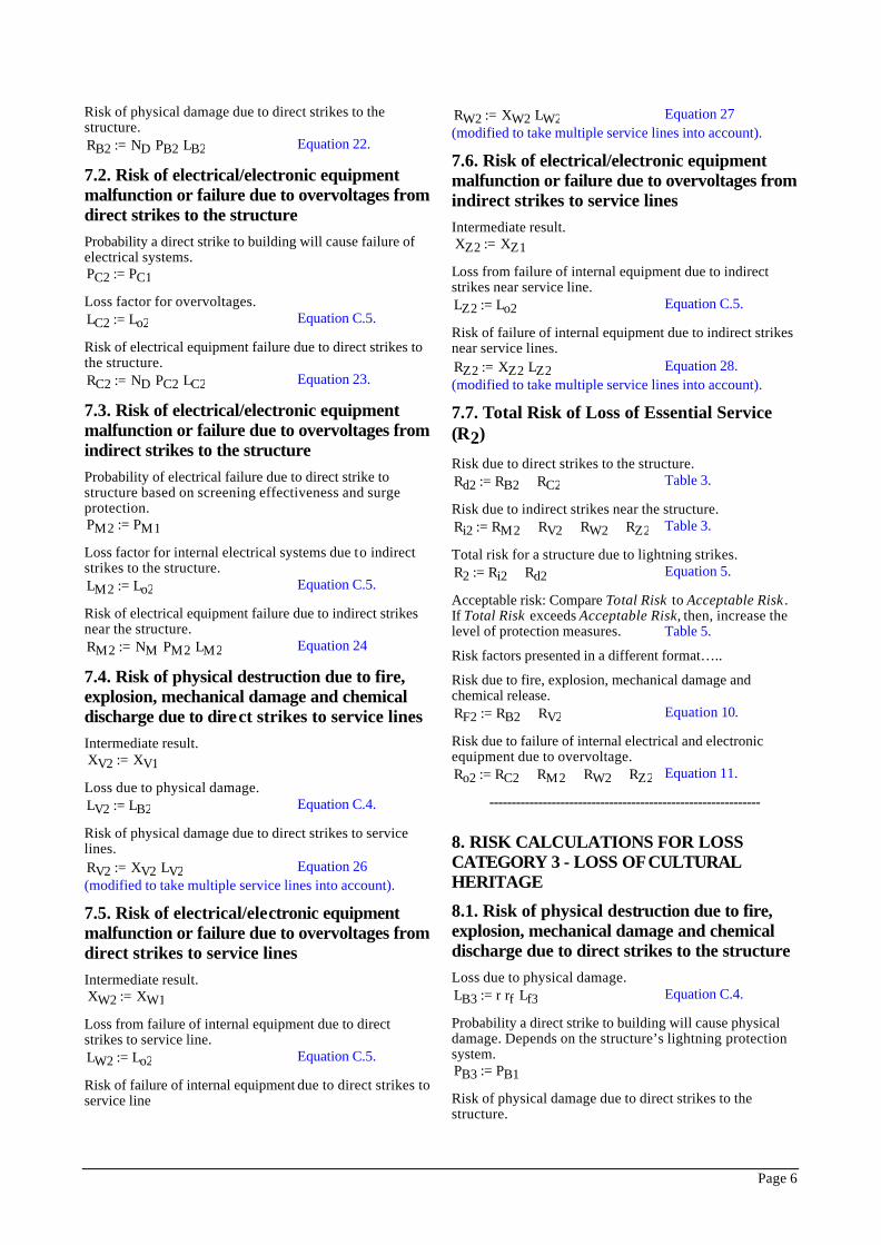
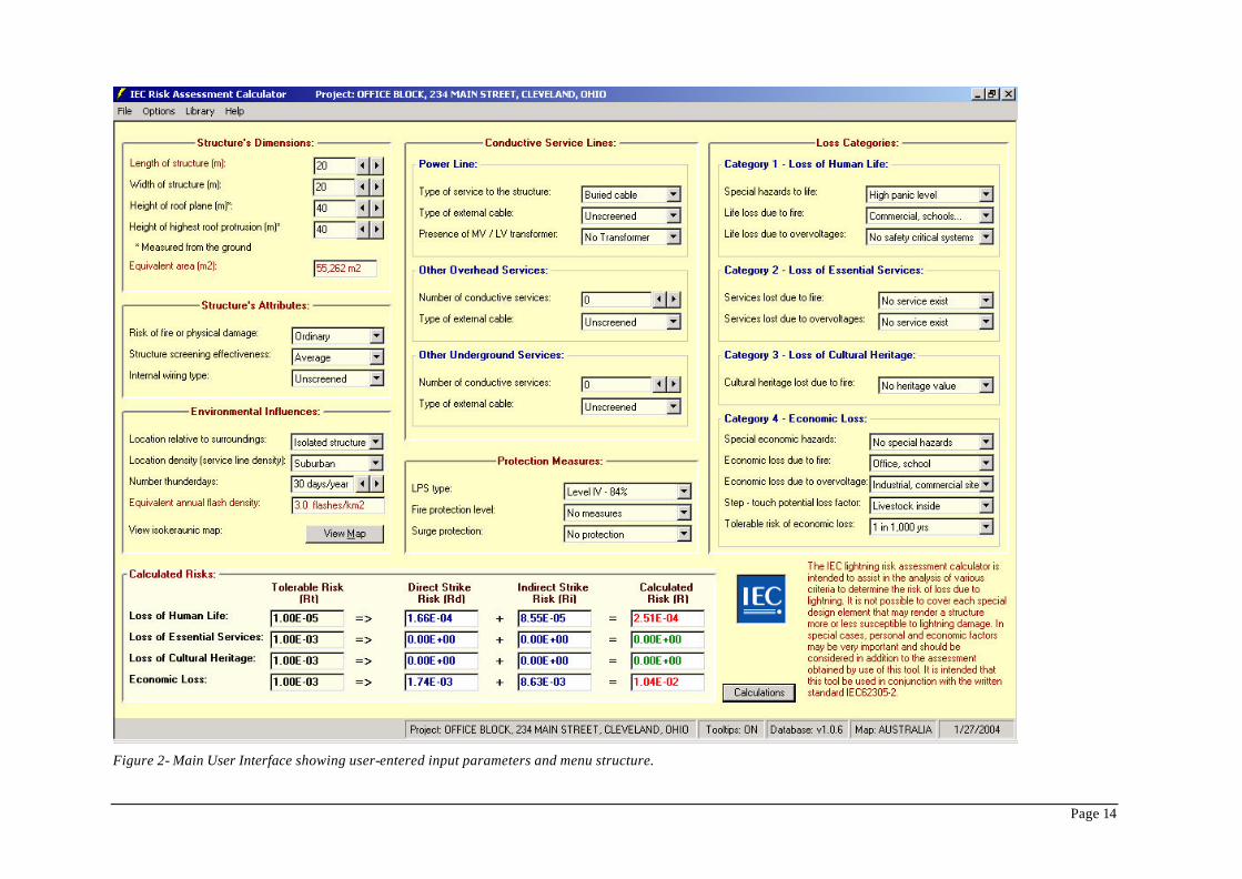
2. OPERATION OF THE SOFTWARE TOOL The user interface of the IEC Risk Assessment Calculator has been designed to fit on a single screen for ease of use, Figure 2. The user starts by making selections from drop-down selection boxes. After each selection, a complete recalculation of the background algorithms is automatically performed and the results displayed in the “Calculated Risks” frame.
As with the written standard, the software tool calculates the risk components of the four areas of risk:
R1 : The risk of loss of Human Life R2 : The risk of loss of Essential Services R3 : The risk of loss of Cultural Heritage value, and R4 : The risk of Economic loss
It further subdivides these risk components into the contributions from a direct lightning discharge and the contribution from an indirect discharge. These calculated risk components are then compared to “Tolerable Risk values” as provided in the standard. Where the calculated risk is lower than the tolerable risk, it is highlighted in

Page 2
Green. Likewise, where the calculated risk exceeds the tolerable risk, it is highlighted in Red, thereby indicating to the user that risk management measures must be taken to lower the risk exposure.
The software tool is unable to provide direction as to how this should be achieved; rather, it is the responsibility of the user in conjunction with an understanding of the standard and the interaction of risk components, to make these adjustments. The tool does however provide the user with a quick and interactive means of assessing which parameters effect the particular risk component needing reduction and also of the relative sensitive of these parameters in making this adjustment.
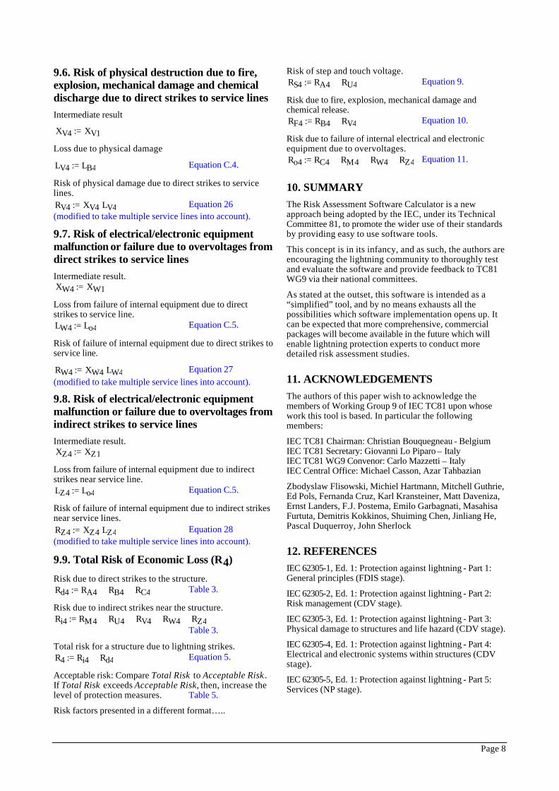
For the more experienced user, a report of the individual components associated with the four loss categories can be viewed by clicking the “Calculations” button – figure 2. This information can be printed and used in conjunction with the written standard to better analyse the risk results and determine measures to improve these where necessary.
Parameters used in the algorithms to calculate the risk components, are divided into three categories:
§ Those where the user can make choices as per the options provided in the written standard.
§ Those where the user’s choices are restricted to a subset of the options provided in the written standard.
§ Those where the values are fixed as constants and inaccessible to be altered.
This data can be viewed in Table 1 through to Table 8.
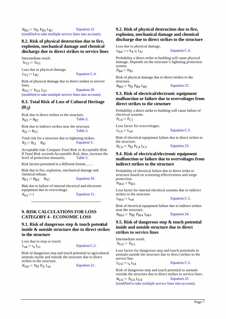
The software tool offers standard windows based features including: the ability to print results, store and retrieve project files, use of interactive tooltips which provide guidance to the user as to the purpose of each drop-down control, an online upgrade facility and the ability to configure the interface for multiple languages - Figure 5.
This last feature is intended to allow the TC81 Working Group to update the database upon which the software relies, with new options and parameters as these become available. It is intended that updates of the software will be limited to releases that coincide with amendments to the written standard. No working group, or IEC central office, support of the software is envisaged. The tool is provided on an “as is” basis and is informative, not normative, to the standard.
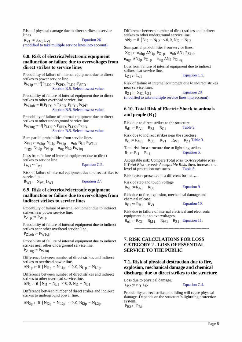
3. STRIKES TO THE STRUCTURE The following sections 3 - 9 provide the equations and algorithms used in the software code to assist the reader in understanding the methods and limitations of the software developed. Where appropriate, references are provided to relevant clauses in IEC 81/241A/CDV (IEC 62305-2 CDV 2), however the reader should be aware that numbering of such clauses is subject to possible change in the FDIS.
Figure 1 - Collection areas (Ad, Am, AL) 3.1. Direct Strikes to the Structure Calculate the collection area in square metres for direct strikes to the structure, based on the intersection of the ground surface by a line with slope of 1/3 that touches the top of the structure – Figure 1.
Ad L W⋅ 6 H⋅ L W+( )⋅+ 9 π⋅ H2
⋅+:= Section A.2.
Compare this to the collection area which would be produced due to the highest roof protrusion and the select the greater of this or the above.
2d H 9 'A π=
Calculate the ground flash density in ground strikes per square kilometre per year.
Ng 0.1 Td⋅ km2−
⋅:= Section A.1.
From this we calculate the average number of direct strikes to the structure per year.
ND Ng Ad⋅ Cd⋅:= Section A.2.
3.2. Indirect Strikes to the Structure Calculate the collection area of influence around the structure within which dangerous overvoltages will be created.
Am L W⋅ 2 Dm⋅ L W+( )⋅+ π Dm2
⋅+ Ad Cd⋅−:= Section A.3.
Limit the minimum value to zero if the height of the structure is too large.
Am if Am 0< 0 km2
⋅, Am,
:=
Section A.3 note.
From this we calculate the average number of strikes direct to the ground or to a grounded object near the structure per year which will cause overvoltages. NM Ng Am⋅:= Equation A.4.
4. OVERHEAD SERVICE LINES Determine the length of the overhead service line based on the user’s selection of service line density - length 1000m for rural, 500m for suburban, 75m for urban. L1 if Ce 0.5> 1000 m⋅, if Ce 0> 500 m⋅, 75 m⋅,( ),( ):=
Calculate the number of overhead power service lines nohp if pl 1 1, 0,( ):=

Page 3
4.1. Direct Strikes to Overhead Lines Lateral distance of overhead line Dc1 3 Hc1⋅:=
Effective length of overhead line Lc1 L1 3 H⋅− 3 ha1⋅−:= Section A.2.
Limit minimum overhead service line length to zero Lc1 if Lc1 0 m⋅≥ Lc1, 0 m⋅,( ):=
Collection area of overhead line Ac1 2 Dc1⋅ Lc1⋅:= Section A.2.
Collection area of direct strikes to adjacent structure (ignored for simplification in this s/w)
Aa1 la1 wa1⋅ 6 ha1⋅ la1 wa1+( )⋅+ 9 π⋅ ha12
⋅+:= Section A.2.
Average number of potentially dangerous direct strikes to the overhead power line per year. NL1p Ng Ac1⋅ Ct0⋅ Cd⋅:= Equation A.5.
Average number of potentially dangerous direct strikes to other conductive overhead lines per year. NL1 Ng Ac1⋅ Ct1⋅ Cd⋅:= Equation A.5.
4.2. Indirect Strikes to Overhead Lines Calculate the collection area within which induced overvoltages due to strikes to ground near the overhead line will be created. Al1 2 Dl1⋅ L1⋅:= Table A.2.
Where Dl1 is the lateral distance at which induced overvoltages due to strikes to ground near the line are considered.
We now calculate the average number of strikes to ground near the overhead power line per year that will cause potentially dangerous induced voltages. NI1p Ng Al1⋅ Ct0⋅ Ce⋅:= Equation A.9.
And the average number of strikes to ground near other conductive overhead lines per year that will cause potentially dangerous induced voltages. NI1 Ng Al1⋅ Ct1⋅ Ce⋅:= Equation A.9.
5. UNDERGROUND SERVICE LINES Determine the length of the underground service line based on the user’s selection of service line density - length 1000m for rural, 500m for suburban, 75m for urban.
Calculate the total number of underground power service lines nugp if pl 2 1, 0,( ):=
5.1. Direct Strikes to Underground Service Lines Calculate the effective length for underground lines, and limit to zero if necessary. Lc2 L2 3 H⋅− 3 ha2⋅−:= Table A.2.
Now calculate the collection area for the underground line, where Dc2 is the lateral distance for induced overvoltages due to direct strikes to the underground line. Ac2 2 Dc2⋅ Lc2⋅:= Table A.2.
Collection area of direct strikes to an adjacent structure.
Aa2 la2 wa2⋅ 6 ha2⋅ la2 wa2+( )⋅+ 9 π⋅ ha22
⋅+:=
Section A.2.
Average number of potentially dangerous strikes direct to the underground power line per year. NL2p Ng Ac2⋅ Ct0⋅ Cd⋅:= Section A.4.
Average number of potentially dangerous strikes direct to other conductive underground line per year. NL2 Ng Ac2⋅ Ct2⋅ Cd⋅:= Section A.4.
5.2. Indirect Strikes to Underground Service Lines Calculate the collection area of induced overvoltages due to strikes to ground near the underground cable, where DI2 is the lateral distance for induced overvoltages due to strikes to ground near the underground cable. Al2 2 Dl2⋅ L2⋅:= Table A.2.
Average number of strikes to the ground near the underground power cable per year which causes potentially dangerous induced voltages. NI2p Ng Al2⋅ Ct0⋅ Ce⋅:= Section A.5.
Average number of strikes to the ground near other underground cable per year which causes potentially dangerous induced voltages. NI2 Ng Al2⋅ Ct2⋅ Ce⋅:= Section A.5.
-------------------------------------------------------------
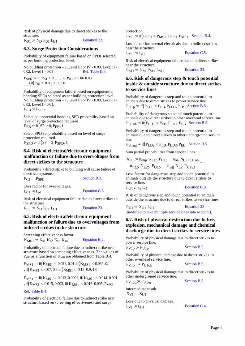
6. RISK CALCULATIONS FOR LOSS CATEGORY 1 - LOSS OF HUMAN LIFE
6.1. Risk of dangerous step & touch potential inside & outside structure due to direct strikes to the structure Loss due to step or touch. La1 ra Lt1⋅:= Equation C.2.
Risk of dangerous step and touch potential to humans and animals inside and up to 3m outside the structure due to direct strikes to the structure. RA1 ND PA⋅ La1⋅:= Equation 21.
6.2. Risk of physical destruction due to fire, explosion, mechanical damage and chemical discharge due to direct strikes to the structure Loss due to physical damage LB1 r h1⋅ rf⋅ Lf1⋅:= Equation C.4.
Probability a direct strike to building will cause physical damage. Depends on structure lightning protection system. PB1 1 E−:=
Page 4
Risk of physical damage due to direct strikes to the structure. RB1 ND PB1⋅ LB1⋅:= Equation 22.
6.3. Surge Protection Considerations Probability of equipment failure based on SPDs selected as per building protection level.
No building protection – 1, Level III or IV - 0.03, Level II - 0.02, Level 1 - 0.01 Ref. Table B.3.
PSPD if PB1 0.3> 1, if PB1 0.06> 0.03, ,,:= …. if PB1 0.03> 0.02, 0.01,( )( ),
Probability of equipment failure based on equipotential bonding SPDs selected as per building protection level. No building protection – 1, Level III or IV - 0.03, Level II - 0.02, Level 1 - 0.01. PEB PSPD:=
Select equipotential bonding SPD probability based on level of surge protection required. PEB if SP 0> PEB, 1,( ):=
Select SPD set probability based on level of surge protection required. PSPD if SP 2 PSPD, 1,( ):=
6.4. Risk of electrical/electronic equipment malfunction or failure due to overvoltages from direct strikes to the structure Probability a direct strike to building will cause failure of electrical systems. PC1 PSPD:= Section B.3.
Loss factor for overvoltages. LC1 Lo1:= Equation C.5.
Risk of electrical equipment failure due to direct strikes to the structure. RC1 ND PC1⋅ LC1⋅:= Equation 23.
6.5. Risk of electrical/electronic equipment malfunction or failure due to overvoltages from indirect strikes to the structure Screening effectiveness factor KMS1 Ks1 Ks2⋅ Ks3⋅ Ks4⋅:= Equation B.2.
Probability of electrical failure due to indirect strike near structure based on screening effectiveness. The values of PMS1 as a function of KMS1 are obtained from Table B.4.
PMS1 if KMS1 0.021≤ 0.01, if KMS1 0.035≤ 0.1,(,(:=0.1 if KMS1 0.07≤ 0.5, if KMS1 0.15≤ 0.9, 1.0,( ),( ), ))
PMS1 if KMS1 0.013≤ 0.0001, if KMS1 0.014≤ 0.001,(,(:=0.001 if KMS1 0.015≤ 0.003, if KMS1 0.016≤ 0.005, PMS1,( ),( ), ))
Ref. Table B.4.
Probability of electrical failure due to indirect strike near structure based on screening effectiveness and surge
protection. PM1 if PSPD PMS1< PSPD, PMS1,( ):=
Section B.4.
Loss factor for internal electricals due to indirect strikes near the structure. LM1 Lo1:= Equation C.5.
Risk of electrical equipment failure due to indirect strikes near the structure. RM1 NM PM1⋅ LM1⋅:= Equation 24.
6.6. Risk of dangerous step & touch potential inside & outside structure due to direct strikes to service lines Probability of dangerous step and touch potential to animals due to direct strikes to power service line. PU1p if PLD0 PEB< PLD0, PEB,( ):=
Section B.5.
Probability of dangerous step and touch potential to animals due to direct strikes to other overhead service line. PU1oh if PLD1 PEB< PLD1, PEB,( ):= Section B.5.
Probability of dangerous step and touch potential to animals due to direct strikes to other underground service line. PU1ug if PLD2 PEB< PLD2, PEB,( ):= Section B.5.
Sum partial probabilities from service lines.
XU1 nohp NL1p⋅ PU1p⋅ noh NL1⋅ PU1oh⋅+:= …..nugp NL2p⋅ PU1p⋅+ nug NL2⋅ PU1ug⋅+
Loss factor for dangerous step and touch potential to animals outside the structure due to direct strikes to service line. LU1 ra Lt1⋅:= Equation C.3.
Risk of dangerous step and touch potential to animals outside the structure due to direct strikes to service lines
RU1 XU1 LU1⋅:= Equation 25 (modified to take multiple service lines into account).
6.7. Risk of physical destruction due to fire, explosion, mechanical damage and chemical discharge due to direct strikes to service lines Probability of physical damage due to direct strikes to power service line. PV1p PU1p:= Section B.5.
Probability of physical damage due to direct strikes to other overhead service line. PV1oh PU1oh:= Section B.5.
Probability of physical damage due to direct strikes to other underground service line. PV1ug PU1ug:= Section B.5.
Intermediate result. XV1 XU1:=
Loss due to physical damage. LV1 LB1:= Equation C.4.
Page 5
Risk of physical damage due to direct strikes to service lines. RV1 XV1 LV1⋅:= Equation 26 (modified to take multiple service lines into account).
6.8. Risk of electrical/electronic equipment malfunction or failure due to overvoltages from direct strikes to service lines Probability of failure of internal equipment due to direct strikes to power service line. PW1p if PLD0 PSPD< PLD0, PSPD,( ):= Section B.5. Select lowest value.
Probability of failure of internal equipment due to direct strikes to other overhead service line. PW1oh if PLD1 PSPD< PLD1, PSPD,( ):= Section B.5. Select lowest value.
Probability of failure of internal equipment due to direct strikes to other underground service line. PW1ug if PLD2 PSPD< PLD2, PSPD,( ):= Section B.5. Select lowest value.
Sum partial probabilities from service lines. XW1 nohp NL1p⋅ PW1p⋅ noh NL1⋅ PW1oh⋅+ +:= nugp NL2p⋅ PW1p⋅ nug NL2⋅ PW1ug⋅+
Loss from failure of internal equipment due to direct strikes to service line. LW1 Lo1:= Equation C.5.
Risk of failure of internal equipment due to direct strikes to service line. RW1 XW1 LW1⋅:= Equation 27.
6.9. Risk of electrical/electronic equipment malfunction or failure due to overvoltages from indirect strikes to service lines Probability of failure of internal equipment due to indirect strikes near power service line. PZ1p PW1p:=
Probability of failure of internal equipment due to indirect strikes near other overhead service line. PZ1oh PW1oh:=
Probability of failure of internal equipment due to indirect strikes near other underground service line. PZ1ug PW1ug:=
Difference between number of direct strikes and indirect strikes to overhead power line. ∆N1p if NI1p NL1p−( ) 0< 0, NI1p NL1p−, :=
Difference between number of direct strikes and indirect strikes to other overhead service line. ∆N1 if NI1 NL1−( ) 0< 0, NI1 NL1−, :=
Difference between number of direct strikes and indirect strikes to underground power line.
∆N2p if NI2p NL2p−( ) 0< 0, NI2p NL2p−, :=
Difference between number of direct strikes and indirect strikes to other underground service line. ∆N2 if NI2 NL2−( ) 0< 0, NI2 NL2−, :=
Sum partial probabilities from service lines. XZ1 nohp ∆N1p⋅ PZ1p⋅ noh ∆N1⋅ PZ1oh⋅+ +:=
nugp ∆N2p⋅ PZ1p⋅ nug ∆N2⋅ PZ1ug⋅+
Loss from failure of internal equipment due to indirect strikes near service line. LZ1 Lo1:= Equation C.5.
Risk of failure of internal equipment due to indirect strikes near service lines. RZ1 XZ1 LZ1⋅:= Equation 28 (modified to take multiple service lines into account).
6.10. Total Risk of Electric Shock to animals and people (R1)
Risk due to direct strikes to the structure Rd1 RA1 RB1+ RC1+:= Table 3.
Risk due to indirect strikes near the structure Ri1 RM1 RU1+ RV1+ RW1+ RZ1+:= Table 3.
Total risk for a structure due to lightning strikes R1 Ri1 Rd1+:= Equation 5.
Acceptable risk: Compare Total Risk to Acceptable Risk . If Total Risk exceeds Acceptable Risk, then, increase the level of protection measures. Table 5.
Risk factors presented in a different format…..
Risk of step and touch voltage RS1 RA1 RU1+:= Equation 9.
Risk due to fire, explosion, mechanical damage and chemical release. RF1 RB1 RV1+:= Equation 10.
Risk due to failure of internal electrical and electronic equipment due to overvoltages. Ro1 RC1 RM1+ RW1+ RZ1+:= Equation 11.
-------------------------------------------------------------
7. RISK CALCULATIONS FOR LOSS CATEGORY 2 - LOSS OF ESSENTIAL SERVICE TO THE PUBLIC
7.1. Risk of physical destruction due to fire, explosion, mechanical damage and chemical discharge due to direct strikes to the structure Loss due to physical damage. LB2 r rf⋅ Lf2⋅:= Equation C.4.
Probability a direct strike to building will cause physical damage. Depends on the structure’s lightning protection system. PB2 PB1:=
Page 6
Risk of physical damage due to direct strikes to the structure. RB2 ND PB2⋅ LB2⋅:= Equation 22.
7.2. Risk of electrical/electronic equipment malfunction or failure due to overvoltages from direct strikes to the structure Probability a direct strike to building will cause failure of electrical systems. PC2 PC1:=
Loss factor for overvoltages. LC2 Lo2:= Equation C.5.
Risk of electrical equipment failure due to direct strikes to the structure. RC2 ND PC2⋅ LC2⋅:= Equation 23.
7.3. Risk of electrical/electronic equipment malfunction or failure due to overvoltages from indirect strikes to the structure Probability of electrical failure due to direct strike to structure based on screening effectiveness and surge protection. PM2 PM1:=
Loss factor for internal electrical systems due to indirect strikes to the structure. LM2 Lo2:= Equation C.5.
Risk of electrical equipment failure due to indirect strikes near the structure. RM2 NM PM2⋅ LM2⋅:= Equation 24
7.4. Risk of physical destruction due to fire, explosion, mechanical damage and chemical discharge due to direct strikes to service lines Intermediate result. XV2 XV1:=
Loss due to physical damage. LV2 LB2:= Equation C.4.
Risk of physical damage due to direct strikes to service lines. RV2 XV2 LV2⋅:= Equation 26 (modified to take multiple service lines into account).
7.5. Risk of electrical/electronic equipment malfunction or failure due to overvoltages from direct strikes to service lines Intermediate result. XW2 XW1:=
Loss from failure of internal equipment due to direct strikes to service line. LW2 Lo2:= Equation C.5.
Risk of failure of internal equipment due to direct strikes to service line
RW2 XW2 LW2⋅:= Equation 27 (modified to take multiple service lines into account).
7.6. Risk of electrical/electronic equipment malfunction or failure due to overvoltages from indirect strikes to service lines Intermediate result. XZ2 XZ1:=
Loss from failure of internal equipment due to indirect strikes near service line. LZ2 Lo2:= Equation C.5.
Risk of failure of internal equipment due to indirect strikes near service lines. RZ2 XZ2 LZ2⋅:= Equation 28. (modified to take multiple service lines into account).
7.7. Total Risk of Loss of Essential Service (R2)
Risk due to direct strikes to the structure. Rd2 RB2 RC2+:= Table 3.
Risk due to indirect strikes near the structure. Ri2 RM2 RV2+ RW2+ RZ2+:= Table 3.
Total risk for a structure due to lightning strikes. R2 Ri2 Rd2+:= Equation 5.
Acceptable risk: Compare Total Risk to Acceptable Risk . If Total Risk exceeds Acceptable Risk, then, increase the level of protection measures. Table 5.
Risk factors presented in a different format…..
Risk due to fire, explosion, mechanical damage and chemical release. RF2 RB2 RV2+:= Equation 10.
Risk due to failure of internal electrical and electronic equipment due to overvoltage. Ro2 RC2 RM2+ RW2+ RZ2+:= Equation 11.
-------------------------------------------------------------
8. RISK CALCULATIONS FOR LOSS CATEGORY 3 - LOSS OF CULTURAL HERITAGE
8.1. Risk of physical destruction due to fire, explosion, mechanical damage and chemical discharge due to direct strikes to the structure Loss due to physical damage. LB3 r rf⋅ Lf3⋅:= Equation C.4.
Probability a direct strike to building will cause physical damage. Depends on the structure’s lightning protection system. PB3 PB1:=
Risk of physical damage due to direct strikes to the structure.
Page 7
RB3 ND PB3⋅ LB3⋅:= Equation 22 (modified to take multiple service lines into account).
8.2. Risk of physical destruction due to fire, explosion, mechanical damage and chemical discharge due to direct strikes to service lines Intermediate result. XV3 XV1:=
Loss due to physical damage. LV3 LB3:= Equation C.4.
Risk of physical damage due to direct strikes to service lines. RV3 XV3 LV3⋅:= Equation 26 (modified to take multiple service lines into account).
8.3. Total Risk of Loss of Cultural Heritage (R3)
Risk due to direct strikes to the structure. Rd3 RB3:= Table 3.
Risk due to indirect strikes near the structure. Ri3 RV3:= Table 3.
Total risk for a structure due to lightning strikes. R3 Ri3 Rd3+:= Equation 5.
Acceptable risk: Compare Total Risk to Acceptable Risk . If Total Risk exceeds Acceptable Risk, then, increase the level of protection measures. Table 5.
Risk factors presented in a different format……
Risk due to fire, explosion, mechanical damage and chemical release. RF3 RB3 RV3+:= Equation 10.
Risk due to failure of internal electrical and electronic equipment due to overvoltage. Ro3 0:= Equation 11.
-------------------------------------------------------------
9. RISK CALCULATIONS FOR LOSS CATEGORY 4 - ECONOMIC LOSS
9.1. Risk of dangerous step & touch potential inside & outside structure due to direct strikes to the structure Loss due to step or touch La4 ra Lt4⋅:= Equation C.2.
Risk of dangerous step and touch potential to agricultural animals inside and outside the structure due to direct strikes to the structure. RA4 ND PA⋅ La4⋅:= Equation 21.
9.2. Risk of physical destruction due to fire, explosion, mechanical damage and chemical discharge due to direct strikes to the structure Loss due to physical damage. LB4 r h4⋅ rf⋅ Lf4⋅:= Equation C.4.
Probability a direct strike to building will cause physical damage. Depends on the structure’s lightning protection system. PB4 PB1:=
Risk of physical damage due to direct strikes to the structure. RB4 ND PB4⋅ LB4⋅:= Equation 22.
9.3. Risk of electrical/electronic equipment malfunction or failure due to overvoltages from direct strikes to the structure Probability a direct strike to building will cause failure of electrical systems. PC4 PC1:=
Loss factor for overvoltages. LC4 Lo4:= Equation C.5.
Risk of electrical equipment failure due to direct strikes to the structure. RC4 ND PC4⋅ LC4⋅:= Equation 23.
9.4. Risk of electrical/electronic equipment malfunction or failure due to overvoltages from indirect strikes to the structure Probability of electrical failure due to direct strike to structure based on screening effectiveness and surge protection. PM4 PM1:=
Loss factor for internal electrical systems due to indirect strikes to the structure. LM4 Lo4:= Equation C.5.
Risk of electrical equipment failure due to indirect strikes near the structure. RM4 NM PM4⋅ LM4⋅:= Equation 24.
9.5. Risk of dangerous step & touch potential inside and outside structure due to direct strikes to service lines Intermediate result. XU4 XU1:=
Loss factor for dangerous step and touch potentials to animals outside the structure due to direct strikes to the service line. LU4 ra Lt4⋅:= Equation C.3.
Risk of dangerous step and touch potential to animals outside the structure due to direct strikes to service lines. RU4 XU4 LU4⋅:= Equation 25 (modified to take multiple service lines into account).
Page 8
9.6. Risk of physical destruction due to fire, explosion, mechanical damage and chemical discharge due to direct strikes to service lines Intermediate result
XV4 XV1:=
Loss due to physical damage
LV4 LB4:= Equation C.4.
Risk of physical damage due to direct strikes to service lines. RV4 XV4 LV4⋅:= Equation 26 (modified to take multiple service lines into account).
9.7. Risk of electrical/electronic equipment malfunction or failure due to overvoltages from direct strikes to service lines Intermediate result. XW4 XW1:=
Loss from failure of internal equipment due to direct strikes to service line. LW4 Lo4:= Equation C.5.
Risk of failure of internal equipment due to direct strikes to service line.
RW4 XW4 LW4⋅:= Equation 27 (modified to take multiple service lines into account).
9.8. Risk of electrical/electronic equipment malfunction or failure due to overvoltages from indirect strikes to service lines Intermediate result. XZ4 XZ1:=
Loss from failure of internal equipment due to indirect strikes near service line. LZ4 Lo4:= Equation C.5.
Risk of failure of internal equipment due to indirect strikes near service lines. RZ4 XZ4 LZ4⋅:= Equation 28 (modified to take multiple service lines into account).
9.9. Total Risk of Economic Loss (R4)
Risk due to direct strikes to the structure. Rd4 RA4 RB4+ RC4+:= Table 3.
Risk due to indirect strikes near the structure. Ri4 RM4 RU4+ RV4+ RW4+ RZ4+:= Table 3.
Total risk for a structure due to lightning strikes. R4 Ri4 Rd4+:= Equation 5.
Acceptable risk: Compare Total Risk to Acceptable Risk . If Total Risk exceeds Acceptable Risk, then, increase the level of protection measures. Table 5.
Risk factors presented in a different format…..
Risk of step and touch voltage. RS4 RA4 RU4+:= Equation 9.
Risk due to fire, explosion, mechanical damage and chemical release. RF4 RB4 RV4+:= Equation 10.
Risk due to failure of internal electrical and electronic equipment due to overvoltages. Ro4 RC4 RM4+ RW4+ RZ4+:= Equation 11.
10. SUMMARY The Risk Assessment Software Calculator is a new approach being adopted by the IEC, under its Technical Committee 81, to promote the wider use of their standards by providing easy to use software tools.
This concept is in its infancy, and as such, the authors are encouraging the lightning community to thoroughly test and evaluate the software and provide feedback to TC81 WG9 via their national committees.
As stated at the outset, this software is intended as a “simplified” tool, and by no means exhausts all the possibilities which software implementation opens up. It can be expected that more comprehensive, commercial packages will become available in the future which will enable lightning protection experts to conduct more detailed risk assessment studies.
11. ACKNOWLEDGEMENTS The authors of this paper wish to acknowledge the members of Working Group 9 of IEC TC81 upon whose work this tool is based. In particular the following members:
IEC TC81 Chairman: Christian Bouquegneau - Belgium IEC TC81 Secretary: Giovanni Lo Piparo – Italy IEC TC81 WG9 Convenor: Carlo Mazzetti – Italy IEC Central Office: Michael Casson, Azar Tahbazian
Zbodyslaw Flisowski, Michiel Hartmann, Mitchell Guthrie, Ed Pols, Fernanda Cruz, Karl Kransteiner, Matt Daveniza, Ernst Landers, F.J. Postema, Emilo Garbagnati, Masahisa Furtuta, Demitris Kokkinos, Shuiming Chen, Jinliang He, Pascal Duquerroy, John Sherlock
12. REFERENCES IEC 62305-1, Ed. 1: Protection against lightning - Part 1: General principles (FDIS stage).
IEC 62305-2, Ed. 1: Protection against lightning - Part 2: Risk management (CDV stage).
IEC 62305-3, Ed. 1: Protection against lightning - Part 3: Physical damage to structures and life hazard (CDV stage).
IEC 62305-4, Ed. 1: Protection against lightning - Part 4: Electrical and electronic systems within structures (CDV stage).
IEC 62305-5, Ed. 1: Protection against lightning - Part 5: Services (NP stage).
Page 9
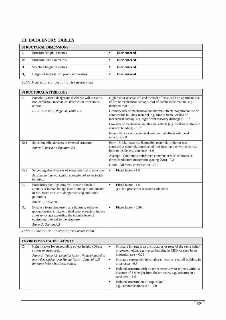
13. DATA ENTRY TABLES STRUCTURAL DIMENSIONS L Structure length in metres § User entered
W Structure width in metres § User entered
H Structure height in metres § User entered
Hp Height of highest roof protrusion metres § User entered
Table 1- Structure undergoing risk assessment
STRUCTURAL ATTRIBUTES rf Probability that a dangerous discharge will initiate a
fire, explosion, mechanical destruction or chemical release. IEC 61662 Ed 2, Page 28, Table B.7.
High risk of mechanical and thermal effects. High or significant risk of fire or mechanical damage, roof of combustible material e.g. thatched roof - 10-1 Ordinary risk of mechanical and thermal effects. Significant use of combustible building material, e.g. timber frame; or risk of mechanical damage, e.g. significant masonry dislodged - 10-2 Low risk of mechanical and thermal effects (e.g. modern reinforced concrete building) - 10-3 None - No risk of mechanical and thermal effects (all metal structure) - 0
Ks1 Screening effectiveness of external structure. Annex B, based on Equation B3.
Poor - Brick, masonry, flammable material, timber or non conducting material, unprotected roof installations with electrical lines to inside, e.g. antennae - 1.0 Average - Continuous reinforced concrete or steel columns or down conductors (maximum spacing 20m) - 0.2 Good - All metal construction - 10-4
Ks2 Screening effectiveness of zones internal to structure. Assume no internal spatial screening of zones inside building.
§ Fixed factor - 1.0
PA Probability that lightning will cause a shock to animals or human beings inside and up to 3m outside of the structure due to dangerous step and touch potentials. Annex B, Table B1.
§ Fixed factor - 1.0 (i.e. No protection measures adopted)
Dm Distance from structure that a lightning strike to ground creates a magnetic field great enough to induce an over-voltage exceeding the impulse level of equipment internal to the structure. Annex A, Section A.3
§ Fixed factor - 250m
Table 2 - Structure undergoing risk assessment
ENVIRONMENTAL INFLUENCES Cd Height factor for surrounding object height. (Direct
strikes to structure). Annex A, Table A1, Location factor. Name changed to more descriptive term Height factor. Value of 0.25 for same height has been added.
§ Structure in large area of structures or trees of the same height or greater height. e.g. typical building in CBD, or shed in an industrial area – 0.25
§ Structure surrounded by smaller structures. e.g. tall building in urban area – 0.5
§ Isolated structure with no other structures or objects within a distance of 3 x height from the structure. e.g. structure in a rural area – 1.0
§ Isolated structure on hilltop or knoll e.g. communications site – 2.0

Page 10
Ce Service Line Density -density factor relating to service drops. Annex A, Table A4, Environment Factor. Name changed to more descriptive term of Service Line Density.
§ Rural (i.e. Sparse e.g. farms) - 1 § Suburban (e.g. Large housing development or suburb) - 0.5 § Urban (i.e. Dense e.g. town or city) - 0
Td Number of thunder days per year § User entered
Ng Equivalent annual flash density § Computed
Table 3 - Location of structure relative to its environment.
BUILDING WIRING Ks3 Screening effectiveness of internal wiring type.
Annex B, Table B5. Reduced number of choices. § Unscreened wiring - 1.0 § Screened (continuously) wiring - 0.1
Table 4 - Building wiring within the structure.
EQUIPMENT Ks4 Correction factor for impulse level of equipment. Fixed factor - 1.0
(applies to impulse withstand level of 1.5 kV)
Table 5 - Electrical / electronic equipment located within the structure.
CONDUCTIVE SERVICE LINES
Power Lines:
pl Power line type. § Aerial - 1.0 § Buried - 2.0 § None – 0
PLD0 Probability of failure of electrical/electronic equipment due to direct or indirect strike to power service line based on external wiring type . Annex B, Table B6. Reduced number of choices.
§ Unscreened wiring - 1.0 § Screened cable with screen earthed or wiring in continuous
metal conduit that is earthed - 0.4
Ct0 Correction factor for the presence of a distribution transformer. Note: A transformer is only possible for the power line. Annex A, Table A3
§ LV line without a transformer - 1.0 § MV line with a HV/LV transformer or isolation transformer -
0.2
Other Overhead Service Lines:
noh Overhead Service Line § User entered - number of overhead service lines in separate routes.
PLD1 Probability of failure of electrical/electronic equipment due to direct or indirect strike to other overhead service line based on external wiring type. Annex B, Table B6. Reduced number of choices.
§ Unscreened wiring – 1 § Screened cable with screen earthed, or wiring in continuous
metal conduit that is earthed - 0.4
Hcl Height of conductors above ground.
§ Fixed value - 6m
DL1 Lateral distance away from the overhead line at which the effects of indirect strikes need to be considered. Annex A, Table A.2.
§ Fixed value - 500m
Ct1 Correction factor for transformer. § Fixed factor - 1 (i.e. no isolation transformer)
la1, wa1, ha1
Dimensions of adjacent structure Simplification made - assume there is no adjacent structure
§ Fixed value - 0m
Conductive Underground Services - Electrical Services e.g. Communication Lines:
nug Number of underground service lines in separate routes.
§ User entered - number of underground service lines in separate routes.

Page 11
routes. separate routes.
PLD2 Probability of failure of electrical/electronic equipment due to direct or indirect strike to other underground service line based on external wiring type. Annex B, Table B6. Reduced number of choices.
§ Unscreened wiring - 1 § Screened cable with screen earthed or wiring in continuous
metal conduit that is earthed - 0.4
P2 Soil resistivity. § Fixed factor - 100 ohm metres.
Ct2 Correction factor for transformer. § Fixed factor – 1 (i.e. no isolation transformer)
la2, wa2, ha2
Dimensions of adjacent structure Simplification made - assume there is no adjacent structure.
§ Fixed value – 0m
Table 6 - Assumes one or no power line(s) and that this is either overhead or underground and that they are in separate routes. The length of service lines is determined from the selection of C e as: "rural", “suburban” or "urban".
ACCEPTABLE RISK & LOSS CATEGORIES
Loss Category 1 - Loss of Human Life:
h1 Special hazards: Increasing factor applied to damage factor for fire and overvoltage when risk of loss of human life is aggravated by special hazards. Annex C, Table C.5.
§ No special hazard – 1 § Low level of panic (building with less than three floors and
less than 100 people) – 2 § Difficulty of evacuation, immobilised people – 5 § Average level of panic (sport or cultural structure with
between 100 and 1000 people) – 5 § High level of panic (theatres, concert halls, cultural & sport
events with more than 1000 people) – 10 § Hazards for surroundings or environment – 20 § Contamination of surroundings or environment – 50
Lf1 Loss factor for fire: Annex C, Table C.1.
§ Hospitals, Hotels, Public buildings - 0.1 § Industrial properties, Properties for commercial activities,
Schools, Offices - 0.05 § Public entertainment buildings, Churches, Museums,
Temporary structure - 0.02 § Other structures - 0.01
Lo1 Loss factor for overvoltages: Annex C, Table C.1 (option "0" added).
§ Properties with risk of explosion - 0.1 § Hospitals - 0.001 § Structures with safety critical systems e.g. high rise with
elevator - 0.00001 § Structures with no safety critical systems e.g. house - 0
RT1 Tolerable risk: Probability of loss of human life per year. Section 5.3, Table 5.
§ Fixed value for loss of human life 10-5
Lt1 Loss factor for step and touch potentials: Unacceptable loss of human life due to step and touch potential inside, and up to 3m outside, the structure. Annex C, Table C.1.
§ Fixed value - 10-4
Ra Reduction factor in loss of human life based on floor/ground contact resistance for step and touch potential inside and up to 3m outside the structure. Annex C, Table C.2 (worst case assumed).
§ Fixed value - 10-2
Loss Category 2 - Loss of Essential Service to the Public:
Lf2 Damage factor for fire: Unacceptable loss of service to the public due to fire.
§ Gas supply, Water supply - 0.1 § Radio, TV, Telecommunications, Power supply, Railway -
0.01

Page 12
Annex C, Table C.6. § No essential service function associated with the structure - 0.0
Lo2 Loss factor due to overvoltages: Unacceptable loss of service to the public due to overvoltages. Annex C, Table C.6.
§ Gas supply, Water supply - 0.01 § Radio, TV, Telecommunications, Power supply, Railway -
0.001 § No essential service function associated with the structure -
0.0
RT2 Tolerable risk: Probability of loss of essential service to the public per year. Section 5.3, Table 5.
§ Fixed value for loss of human life - 10-3
Loss Category 3 - Loss of Cultural Heritage: (It is assumed that there are no electronic devices inside)
Lf3 Damage factor for fire: Unacceptable loss of irreplaceable cultural heritage due to fire. Annex C, Table C.4.
§ Typical value - 0.1 § No cultural heritage value - 0.0
RT3 Tolerable risk: Probability of loss of cultural heritage per year. Section 5.3, Table 5.
§ Fixed value for loss of cultural heritage - 10-3
Loss Category 4 - Economic Loss:
h4 Increasing factor applied to situation where environmental hazards exist. Annex C, Table C.5, reduced number of options.
§ No special hazard – 1 § Hazards for surroundings or environment – 20 § Contamination of surroundings or environment – 50
Lf4 Loss factor for fire: Unacceptable economic loss due to fire (average value of possible loss / total value of structure, contents & activities). Annex C, Section C.5. (estimated values for different structures).
Typical values of economic loss: § Hospitals, Industrial properties, Museum, Agricultural
properties - 0.5 § Properties for public use, Hotels, Offices, Schools,
Commercial activities, Public entertainment, Prisons, Churches - 0.2
§ Others - 0.1
Lo4 Loss factor due to overvoltages: Unacceptable economic loss due to overvoltages (average value of possible loss / total value structure, contents & activities). Annex C, Section C.5. (estimated values for different structures).
§ Risk of explosion - 0.1 § Hospitals, Hotels, Industrial properties, Offices, Commercial
activities - 0.01 § Museum, Properties for public use, Agricultural properties,
Schools, Public entertainment, Prisons, Churches - 0.001 § Others - 0.0001
Lt4 Loss factor for step and touch potentials: Unacceptable economic loss due to step and touch potential inside, and up to 3m outside, the structure. Annex C, Section C.5.
§ Agricultural properties with animals inside or outside the structure - 0.01
§ Agricultural properties with no animal shock risk – 0
RT4 Tolerable risk: Probability of economic loss per year.
§ Depends on the structure owner’s requirement. Range available is 0.1, 0.01, 0.001, 0.0001, 0.00001.
§ Suggested default value if unknown - 0.001 (i.e. 1 in 1000 year probability of economic loss).
Table 7 - Tolerable risk and loss factors
PROTECTION MEASURES IMPLEMENTED E Efficiency of lightning protection system on the
structure: Takes into account interception and sizing efficiencies. Assumes surge protection is applied to either all OR none of the internal equipment within the structure.
§ Level I - 99% § Level II - 97% § Level III - 91% § Level IV - 84% § No protection - 0.

Page 13
r Reduction factor for fire protection measures: Annex C, Table C.3.
§ No protection measures - 1.0 § Extinguishers, hydrants, manual alarm installations, fixed
manually operated extinguishing installations - 0.5 § Protected escape routes, fire proof compartments, automatic
alarms protected from overvoltage, automatically operated extinguishers, operating time of escape routes less than 10 minutes - 0.2.
SP Surge protection. Note: The user’s selection of surge protection applies to all services and the entire structure being protected.
§ No surge protection – 0 § Equipotential bonding SPDs at the entry points of service
lines – 1.0 § Full Surge Protection “SPD Set” as detailed in IEC 62305-4: -
2.0
Table 8 - Measures adopted on the structure to reduce damage due to lightning
Page 14
Figure 2- Main User Interface showing user-entered input parameters and menu structure.

Page 15
Figure 3- Main User Interface showing use of tooltips to guide the user through the interface selections.

Page 16
Figure 4- The calculations at each stage can be viewed when needing to evaluate the output in conjunction with the written standard.

Page 17
Figure 5 - The interface currently supports a number of different languages. The software has been developed in such a way as to allow National Committees to develop their own translations for local market consumption.

Cálculo del sistema de
protección contra el rayo
RFE-1-YE_-ECE-IDO-005
Rev.A Pág/Page 16 de/of 17
Este documento contiene información propiedad de Cobra y está sujeto a las restricciones detalladas en la página de portada.
La única copia controlada de este documento es la incluida en la intranet de Cobra.
This document contains proprietary information of Cobra and is subject to the restrictions set forth on the title page.
The only controlled copy of the document is located on the Cobra intranet.
ANEXO 2:
RIESGO DE LOS DIFERENTES EDIFICIOS
NORME CEIINTERNATIONALE IEC
INTERNATIONAL 62305-2STANDARD Edition-1
2005-01
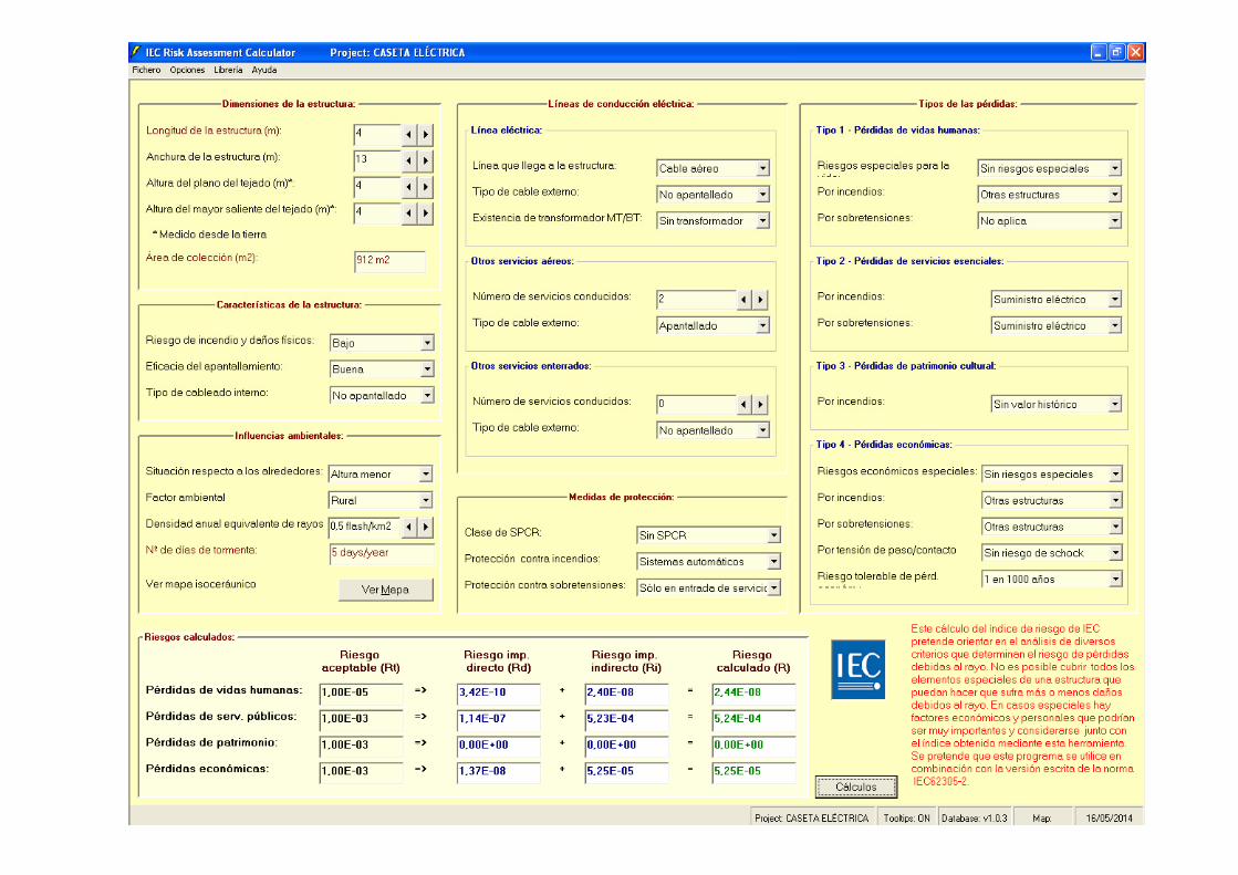
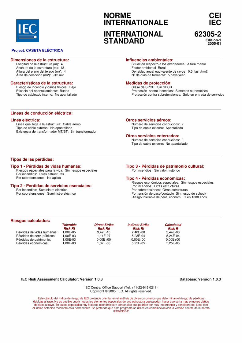
Project: CASETA ELÉCTRICA
Dimensiones de la estructura:Longitud de la estructura (m): 4Anchura de la estructura (m): 13Altura del plano del tejado (m)*: 4Área de colección (m2): 912 m2
Características de la estructura:Riesgo de incendio y daños físicos: BajoEficacia del apantallamiento: BuenaTipo de cableado interno: No apantallado
Influencias ambientales:Situación respecto a los alrededores: Altura menorFactor ambiental RuralDensidad anual equivalente de rayos 0,5 flash/km2Nº de días de tormenta: 5 days/year
Medidas de protección:Clase de SPCR: Sin SPCRProtección contra incendios: Sistemas automáticosProtección contra sobretensiones: Sólo en entrada de servicios
Líneas de conducción eléctrica:
Línea eléctrica:Línea que llega a la estructura: Cable aéreoTipo de cable externo: No apantalladoExistencia de transformador MT/BT: Sin transformador
Otros servicios aéreos:Número de servicios conducidos: 2Tipo de cable externo: Apantallado
Otros servicios enterrados:Número de servicios conducidos: 0Tipo de cable externo: No apantallado
Tipos de las pérdidas:
Tipo 1 - Pérdidas de vidas humanas:Riesgos especiales para la vida: Sin riesgos especialesPor incendios: Otras estructurasPor sobretensiones: No aplica
Tipo 2 - Pérdidas de servicios esenciales:Por incendios: Suministro eléctricoPor sobretensiones: Suministro eléctrico
Tipo 3 - Pérdidas de patrimonio cultural:Por incendios: Sin valor histórico
Tipo 4 - Pérdidas económicas:Riesgos económicos especiales: Sin riesgos especialesPor incendios: Otras estructurasPor sobretensiones: Otras estructurasPor tensión de paso/contacto Sin riesgo de schockRiesgo tolerable de pérd. económ.: 1 en 1000 años
Riesgos calculados:Tolerable Direct Strike Indirect Strike Calculated
Risk Rt Risk Rd Risk Ri Risk R
Pérdidas de vidas humanas:Pérdidas de serv. públicos:Pérdidas de patrimonio:Pérdidas económicas:
1,00E-05 3,42E-10 2,40E-08 2,44E-081,00E-03 1,14E-07 5,23E-04 5,24E-041,00E-03 0,00E+00 0,00E+00 0,00E+001,00E-03 1,37E-08 5,25E-05 5,25E-05
IEC Risk Assessment Calculator: Version 1.0.3 Database: Version 1.0.3
IEC Central Office Support (Tel: +41-22-919 0211)Copyright © 2005, IEC. All rights reserved.
Este cálculo del índice de riesgo de IEC pretende orientar en el análisis de diversos criterios que determinan el riesgo de pérdidasdebidas al rayo. No es posible cubrir todos los elementos especiales de una estructura que puedan hacer que sufra más o menos dañosdebidos al rayo. En casos especiales hay factores económicos y personales que podrían ser muy importantes y considerarse junto con
el índice obtenido mediante esta herramienta. Se pretende que este programa se utilice en combinación con la versión escrita de la norma IEC62305-2.

NORME CEIINTERNATIONALE IEC
INTERNATIONAL 62305-2STANDARD Edition-1
2005-01
Project: CHIMENEA GENERADOR AUXILIAR
Dimensiones de la estructura:Longitud de la estructura (m): 2Anchura de la estructura (m): 2Altura del plano del tejado (m)*: 35Área de colección (m2): 34.636 m2
Características de la estructura:Riesgo de incendio y daños físicos: BajoEficacia del apantallamiento: BuenaTipo de cableado interno: No apantallado
Influencias ambientales:Situación respecto a los alrededores: Altura similarFactor ambiental RuralDensidad anual equivalente de rayos 0,5 flash/km2Nº de días de tormenta: 5 days/year
Medidas de protección:Clase de SPCR: Sin SPCRProtección contra incendios: Sin medidasProtección contra sobretensiones: Sin protección
Líneas de conducción eléctrica:
Línea eléctrica:Línea que llega a la estructura: Cable aéreoTipo de cable externo: No apantalladoExistencia de transformador MT/BT: Sin transformador
Otros servicios aéreos:Número de servicios conducidos: 0Tipo de cable externo: No apantallado
Otros servicios enterrados:Número de servicios conducidos: 0Tipo de cable externo: No apantallado
Tipos de las pérdidas:
Tipo 1 - Pérdidas de vidas humanas:Riesgos especiales para la vida: Sin riesgos especialesPor incendios: Otras estructurasPor sobretensiones: No aplica
Tipo 2 - Pérdidas de servicios esenciales:Por incendios: Suministro eléctricoPor sobretensiones: Suministro eléctrico
Tipo 3 - Pérdidas de patrimonio cultural:Por incendios: Sin valor histórico
Tipo 4 - Pérdidas económicas:Riesgos económicos especiales: Sin riesgos especialesPor incendios: Otras estructurasPor sobretensiones: Otras estructurasPor tensión de paso/contacto Sin riesgo de schockRiesgo tolerable de pérd. económ.: 1 en 1000 años
Riesgos calculados:Tolerable Direct Strike Indirect Strike Calculated
Risk Rt Risk Rd Risk Ri Risk R
Pérdidas de vidas humanas:Pérdidas de serv. públicos:Pérdidas de patrimonio:Pérdidas económicas:
1,00E-05 9,52E-08 8,95E-08 1,85E-071,00E-03 8,75E-06 5,00E-04 5,09E-041,00E-03 0,00E+00 0,00E+00 0,00E+001,00E-03 1,73E-06 5,08E-05 5,25E-05
IEC Risk Assessment Calculator: Version 1.0.3 Database: Version 1.0.3
IEC Central Office Support (Tel: +41-22-919 0211)Copyright © 2005, IEC. All rights reserved.
Este cálculo del índice de riesgo de IEC pretende orientar en el análisis de diversos criterios que determinan el riesgo de pérdidasdebidas al rayo. No es posible cubrir todos los elementos especiales de una estructura que puedan hacer que sufra más o menos dañosdebidos al rayo. En casos especiales hay factores económicos y personales que podrían ser muy importantes y considerarse junto con
el índice obtenido mediante esta herramienta. Se pretende que este programa se utilice en combinación con la versión escrita de la norma IEC62305-2.
NORME CEIINTERNATIONALE IEC
INTERNATIONAL 62305-2STANDARD Edition-1
2005-01
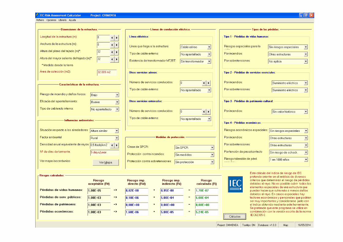
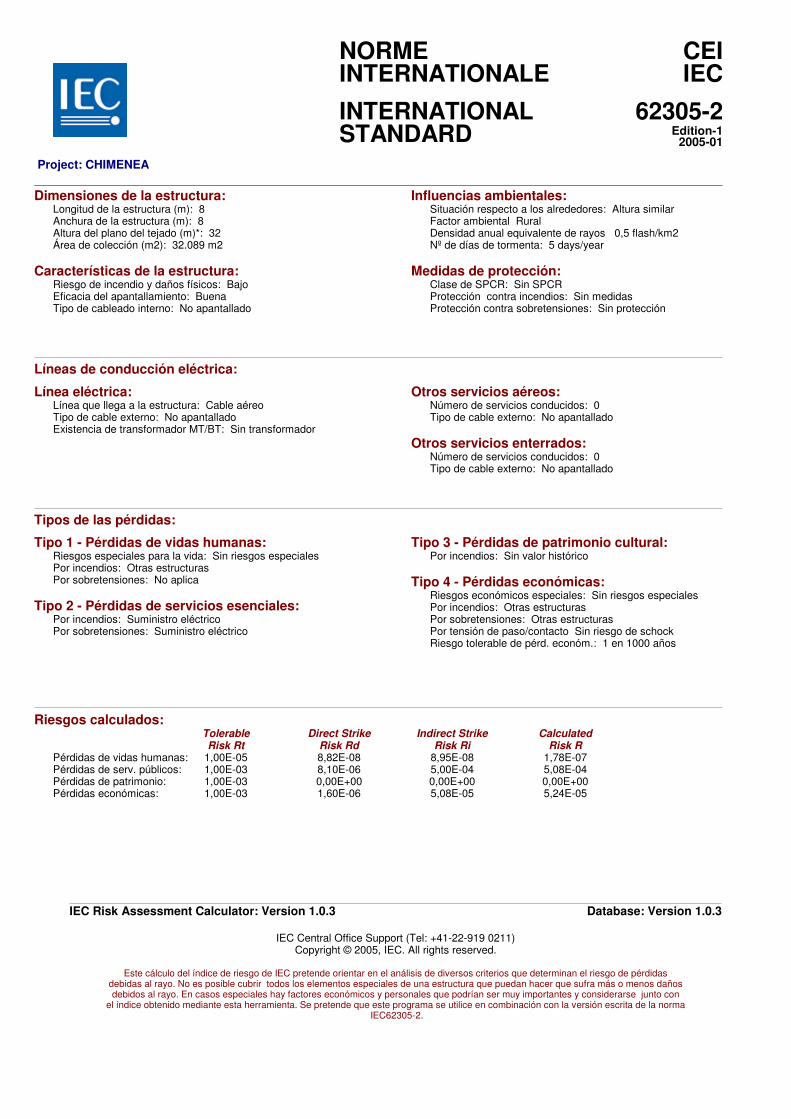
Project: CHIMENEA
Dimensiones de la estructura:Longitud de la estructura (m): 8Anchura de la estructura (m): 8Altura del plano del tejado (m)*: 32Área de colección (m2): 32.089 m2
Características de la estructura:Riesgo de incendio y daños físicos: BajoEficacia del apantallamiento: BuenaTipo de cableado interno: No apantallado
Influencias ambientales:Situación respecto a los alrededores: Altura similarFactor ambiental RuralDensidad anual equivalente de rayos 0,5 flash/km2Nº de días de tormenta: 5 days/year
Medidas de protección:Clase de SPCR: Sin SPCRProtección contra incendios: Sin medidasProtección contra sobretensiones: Sin protección
Líneas de conducción eléctrica:
Línea eléctrica:Línea que llega a la estructura: Cable aéreoTipo de cable externo: No apantalladoExistencia de transformador MT/BT: Sin transformador
Otros servicios aéreos:Número de servicios conducidos: 0Tipo de cable externo: No apantallado
Otros servicios enterrados:Número de servicios conducidos: 0Tipo de cable externo: No apantallado
Tipos de las pérdidas:
Tipo 1 - Pérdidas de vidas humanas:Riesgos especiales para la vida: Sin riesgos especialesPor incendios: Otras estructurasPor sobretensiones: No aplica
Tipo 2 - Pérdidas de servicios esenciales:Por incendios: Suministro eléctricoPor sobretensiones: Suministro eléctrico
Tipo 3 - Pérdidas de patrimonio cultural:Por incendios: Sin valor histórico
Tipo 4 - Pérdidas económicas:Riesgos económicos especiales: Sin riesgos especialesPor incendios: Otras estructurasPor sobretensiones: Otras estructurasPor tensión de paso/contacto Sin riesgo de schockRiesgo tolerable de pérd. económ.: 1 en 1000 años
Riesgos calculados:Tolerable Direct Strike Indirect Strike Calculated
Risk Rt Risk Rd Risk Ri Risk R
Pérdidas de vidas humanas:Pérdidas de serv. públicos:Pérdidas de patrimonio:Pérdidas económicas:
1,00E-05 8,82E-08 8,95E-08 1,78E-071,00E-03 8,10E-06 5,00E-04 5,08E-041,00E-03 0,00E+00 0,00E+00 0,00E+001,00E-03 1,60E-06 5,08E-05 5,24E-05
IEC Risk Assessment Calculator: Version 1.0.3 Database: Version 1.0.3
IEC Central Office Support (Tel: +41-22-919 0211)Copyright © 2005, IEC. All rights reserved.
Este cálculo del índice de riesgo de IEC pretende orientar en el análisis de diversos criterios que determinan el riesgo de pérdidasdebidas al rayo. No es posible cubrir todos los elementos especiales de una estructura que puedan hacer que sufra más o menos dañosdebidos al rayo. En casos especiales hay factores económicos y personales que podrían ser muy importantes y considerarse junto con
el índice obtenido mediante esta herramienta. Se pretende que este programa se utilice en combinación con la versión escrita de la norma IEC62305-2.

NORME CEIINTERNATIONALE IEC
INTERNATIONAL 62305-2STANDARD Edition-1
2005-01
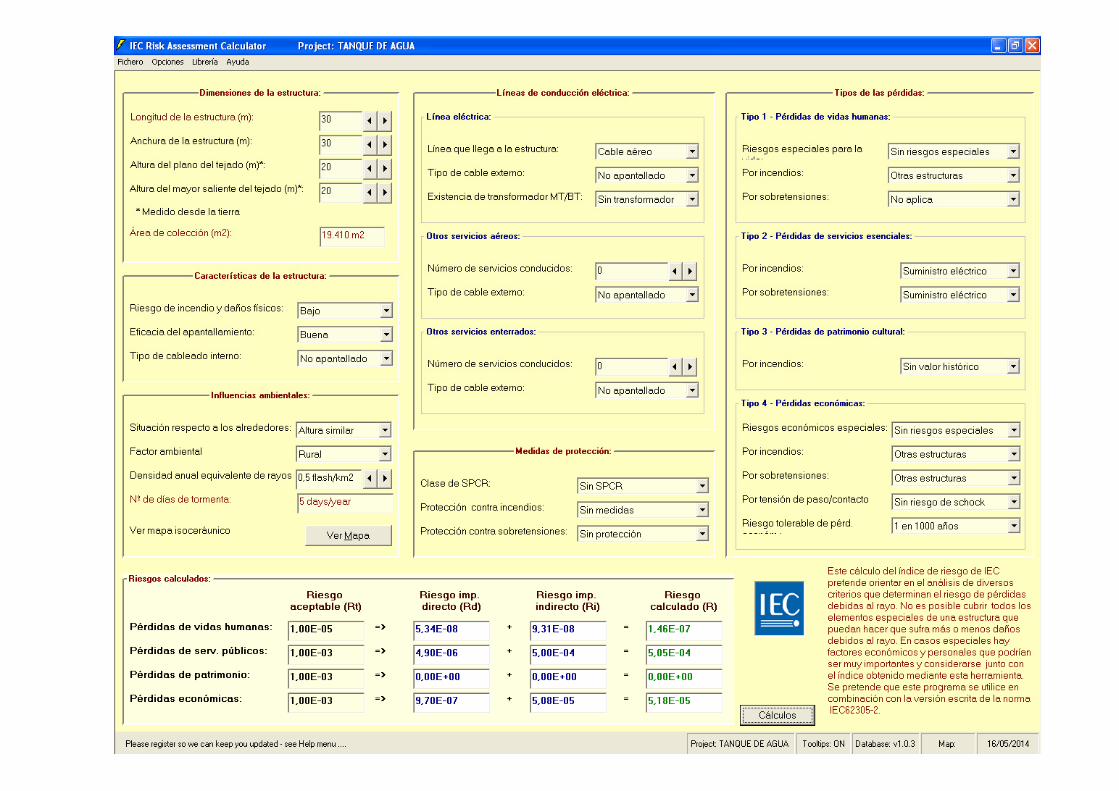
Project: TANQUE DE AGUA
Dimensiones de la estructura:Longitud de la estructura (m): 30Anchura de la estructura (m): 30Altura del plano del tejado (m)*: 20Área de colección (m2): 19.410 m2
Características de la estructura:Riesgo de incendio y daños físicos: BajoEficacia del apantallamiento: BuenaTipo de cableado interno: No apantallado
Influencias ambientales:Situación respecto a los alrededores: Altura similarFactor ambiental RuralDensidad anual equivalente de rayos 0,5 flash/km2Nº de días de tormenta: 5 days/year
Medidas de protección:Clase de SPCR: Sin SPCRProtección contra incendios: Sin medidasProtección contra sobretensiones: Sin protección
Líneas de conducción eléctrica:
Línea eléctrica:Línea que llega a la estructura: Cable aéreoTipo de cable externo: No apantalladoExistencia de transformador MT/BT: Sin transformador
Otros servicios aéreos:Número de servicios conducidos: 0Tipo de cable externo: No apantallado
Otros servicios enterrados:Número de servicios conducidos: 0Tipo de cable externo: No apantallado
Tipos de las pérdidas:
Tipo 1 - Pérdidas de vidas humanas:Riesgos especiales para la vida: Sin riesgos especialesPor incendios: Otras estructurasPor sobretensiones: No aplica
Tipo 2 - Pérdidas de servicios esenciales:Por incendios: Suministro eléctricoPor sobretensiones: Suministro eléctrico
Tipo 3 - Pérdidas de patrimonio cultural:Por incendios: Sin valor histórico
Tipo 4 - Pérdidas económicas:Riesgos económicos especiales: Sin riesgos especialesPor incendios: Otras estructurasPor sobretensiones: Otras estructurasPor tensión de paso/contacto Sin riesgo de schockRiesgo tolerable de pérd. económ.: 1 en 1000 años
Riesgos calculados:Tolerable Direct Strike Indirect Strike Calculated
Risk Rt Risk Rd Risk Ri Risk R
Pérdidas de vidas humanas:Pérdidas de serv. públicos:Pérdidas de patrimonio:Pérdidas económicas:
1,00E-05 5,34E-08 9,31E-08 1,46E-071,00E-03 4,90E-06 5,00E-04 5,05E-041,00E-03 0,00E+00 0,00E+00 0,00E+001,00E-03 9,70E-07 5,08E-05 5,18E-05
IEC Risk Assessment Calculator: Version 1.0.3 Database: Version 1.0.3
IEC Central Office Support (Tel: +41-22-919 0211)Copyright © 2005, IEC. All rights reserved.
Este cálculo del índice de riesgo de IEC pretende orientar en el análisis de diversos criterios que determinan el riesgo de pérdidasdebidas al rayo. No es posible cubrir todos los elementos especiales de una estructura que puedan hacer que sufra más o menos dañosdebidos al rayo. En casos especiales hay factores económicos y personales que podrían ser muy importantes y considerarse junto con
el índice obtenido mediante esta herramienta. Se pretende que este programa se utilice en combinación con la versión escrita de la norma IEC62305-2.

NORME CEIINTERNATIONALE IEC
INTERNATIONAL 62305-2STANDARD Edition-1
2005-01
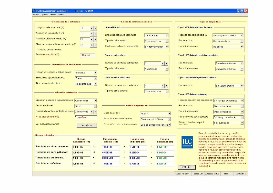
Project: TANQUES COMBUSTIBLE
Dimensiones de la estructura:Longitud de la estructura (m): 23Anchura de la estructura (m): 23Altura del plano del tejado (m)*: 25Área de colección (m2): 25.100 m2
Características de la estructura:Riesgo de incendio y daños físicos: ExplosivoEficacia del apantallamiento: BuenaTipo de cableado interno: No apantallado
Influencias ambientales:Situación respecto a los alrededores: Altura similarFactor ambiental RuralDensidad anual equivalente de rayos 0,5 flash/km2Nº de días de tormenta: 5 days/year
Medidas de protección:Clase de SPCR: Nivel IVProtección contra incendios: Sistemas automáticosProtección contra sobretensiones: Sólo en entrada de servicios
Líneas de conducción eléctrica:
Línea eléctrica:Línea que llega a la estructura: Cable aéreoTipo de cable externo: No apantalladoExistencia de transformador MT/BT: Sin transformador
Otros servicios aéreos:Número de servicios conducidos: 0Tipo de cable externo: Apantallado
Otros servicios enterrados:Número de servicios conducidos: 0Tipo de cable externo: No apantallado
Tipos de las pérdidas:
Tipo 1 - Pérdidas de vidas humanas:Riesgos especiales para la vida: Sin riesgos especialesPor incendios: Otras estructurasPor sobretensiones: No aplica
Tipo 2 - Pérdidas de servicios esenciales:Por incendios: Suministro eléctricoPor sobretensiones: Suministro eléctrico
Tipo 3 - Pérdidas de patrimonio cultural:Por incendios: Sin valor histórico
Tipo 4 - Pérdidas económicas:Riesgos económicos especiales: Sin riesgos especialesPor incendios: Otras estructurasPor sobretensiones: Otras estructurasPor tensión de paso/contacto Sin riesgo de schockRiesgo tolerable de pérd. económ.: 1 en 1000 años
Riesgos calculados:Tolerable Direct Strike Indirect Strike Calculated
Risk Rt Risk Rd Risk Ri Risk R
Pérdidas de vidas humanas:Pérdidas de serv. públicos:Pérdidas de patrimonio:Pérdidas económicas:
1,00E-05 2,52E-06 5,00E-07 3,02E-061,00E-03 8,79E-06 5,01E-04 5,09E-041,00E-03 0,00E+00 0,00E+00 0,00E+001,00E-03 2,57E-05 5,50E-05 8,07E-05
IEC Risk Assessment Calculator: Version 1.0.3 Database: Version 1.0.3
IEC Central Office Support (Tel: +41-22-919 0211)Copyright © 2005, IEC. All rights reserved.
Este cálculo del índice de riesgo de IEC pretende orientar en el análisis de diversos criterios que determinan el riesgo de pérdidasdebidas al rayo. No es posible cubrir todos los elementos especiales de una estructura que puedan hacer que sufra más o menos dañosdebidos al rayo. En casos especiales hay factores económicos y personales que podrían ser muy importantes y considerarse junto con
el índice obtenido mediante esta herramienta. Se pretende que este programa se utilice en combinación con la versión escrita de la norma IEC62305-2.

NORME CEIINTERNATIONALE IEC
INTERNATIONAL 62305-2STANDARD Edition-1
2005-01
Project: TURBINA
Dimensiones de la estructura:Longitud de la estructura (m): 14Anchura de la estructura (m): 11Altura del plano del tejado (m)*: 23Área de colección (m2): 18.561 m2
Características de la estructura:Riesgo de incendio y daños físicos: ExplosivoEficacia del apantallamiento: BuenaTipo de cableado interno: No apantallado
Influencias ambientales:Situación respecto a los alrededores: Altura similarFactor ambiental RuralDensidad anual equivalente de rayos 0,5 flash/km2Nº de días de tormenta: 5 days/year
Medidas de protección:Clase de SPCR: Nivel IVProtección contra incendios: Sistemas automáticosProtección contra sobretensiones: Sólo en entrada de servicios
Líneas de conducción eléctrica:
Línea eléctrica:Línea que llega a la estructura: Cable aéreoTipo de cable externo: No apantalladoExistencia de transformador MT/BT: Sin transformador
Otros servicios aéreos:Número de servicios conducidos: 2Tipo de cable externo: Apantallado
Otros servicios enterrados:Número de servicios conducidos: 0Tipo de cable externo: No apantallado
Tipos de las pérdidas:
Tipo 1 - Pérdidas de vidas humanas:Riesgos especiales para la vida: Sin riesgos especialesPor incendios: Otras estructurasPor sobretensiones: No aplica
Tipo 2 - Pérdidas de servicios esenciales:Por incendios: Suministro eléctricoPor sobretensiones: Suministro eléctrico
Tipo 3 - Pérdidas de patrimonio cultural:Por incendios: Sin valor histórico
Tipo 4 - Pérdidas económicas:Riesgos económicos especiales: Sin riesgos especialesPor incendios: Otras estructurasPor sobretensiones: Otras estructurasPor tensión de paso/contacto Sin riesgo de schockRiesgo tolerable de pérd. económ.: 1 en 1000 años
Riesgos calculados:Tolerable Direct Strike Indirect Strike Calculated
Risk Rt Risk Rd Risk Ri Risk R
Pérdidas de vidas humanas:Pérdidas de serv. públicos:Pérdidas de patrimonio:Pérdidas económicas:
1,00E-05 1,86E-06 1,51E-06 3,37E-061,00E-03 6,50E-06 5,28E-04 5,34E-041,00E-03 0,00E+00 0,00E+00 0,00E+001,00E-03 1,90E-05 6,77E-05 8,67E-05
IEC Risk Assessment Calculator: Version 1.0.3 Database: Version 1.0.3
IEC Central Office Support (Tel: +41-22-919 0211)Copyright © 2005, IEC. All rights reserved.
Este cálculo del índice de riesgo de IEC pretende orientar en el análisis de diversos criterios que determinan el riesgo de pérdidasdebidas al rayo. No es posible cubrir todos los elementos especiales de una estructura que puedan hacer que sufra más o menos dañosdebidos al rayo. En casos especiales hay factores económicos y personales que podrían ser muy importantes y considerarse junto con
el índice obtenido mediante esta herramienta. Se pretende que este programa se utilice en combinación con la versión escrita de la norma IEC62305-2.
Cálculo del sistema de
protección contra el rayo
RFE-1-YE_-ECE-IDO-005
Rev.A Pág/Page 17 de/of 17
Este documento contiene información propiedad de Cobra y está sujeto a las restricciones detalladas en la página de portada.
La única copia controlada de este documento es la incluida en la intranet de Cobra.
This document contains proprietary information of Cobra and is subject to the restrictions set forth on the title page.
The only controlled copy of the document is located on the Cobra intranet.
ANEXO 3:
CÁLCULOS