Revista Ingeniería de Construcción RIC Vol 28 Nº3 … · 252 Revista Ingeniería de...
15
251 Revista Ingeniería de Construcción Vol. 28 Nº3, Diciembre de 2013 www.ricuc.cl Revista Ingeniería de Construcción RIC Vol 28 Nº3 2013 http://www.ricuc.cl .................................................................................................................................................................................................................................................................................... Aplicación de la teoría de seguridad al diseño geotécnico de losas sobre pilotes Application of the safety theory to the geotechnical design of piled raft foundations Raydel Lorenzo*, Renato P. da Cunha*, Elizabeth Hernandez*, Willian Cobelo 1 ** * Universidad de Brasília, Brasília. BRASIL ** Instituto Superior Politécnico José Antonio Echeverría, Ciudad de la Habana. CUBA Fecha de Recepción:11/09/2013 Fecha de Aceptación:10/11/2013 PAG 251 -265 Resumen En este artículo se da una panorámica de los métodos de cálculo de la capacidad de carga de cimentaciones de tipo losa sobre pilotes (piled raft) seleccionando, de acuerdo al estudio bibliográfico realizado, el que arroja resultados más cercanos a estudios de experimentales y numéricos. Se presenta la forma de aplicación del método de estados límites al diseño geotécnico de este tipo de cimentación, definiendo el sistema de coeficientes parciales necesarios para la introducción de la seguridad a través de este método para el estado último. Se muestra la aplicación de la Teoría de Seguridad y de los métodos probabilísticos en el diseño geotécnico, definiendo todo el aparato matemático necesario en el caso específico de las losas sobre pilotes. Finalmente se presenta la metodología para la calibración de los coeficientes parciales a utilizar en el método de estados límites a partir de la aplicación de los métodos probabilísticos y se obtienen, para el método seleccionado de determinación de la capacidad de carga, todas las expresiones necesarias para la calibración en el caso específico de las losas sobre pilotes. Palabras Clave: Losas pilotadas, métodos probabilísticos, teoría de seguridad Abstract This paper reviews the principal calculation methods to estimate bearing capacity of piled raft foundations, selecting for further analysis the one with the closest results to field studies and numerical analysis. The application of the Limit State Method to geotechnical design of this kind of foundation is presented with the purpose of establishing a methodology for the calculation of bearing capacity of a piled raft. The partial coefficients necessary to introduce safety in this method are defined for the ultimate limit state. The application of the Safety Theory and probabilistic methods in the geotechnical design is presented, as well as the mathematic formulation for its implementation in piled raft foundation. A methodology for the adjustment of partial coefficients (to be used for the method of limit states) based on probabilistic methods is proposed. The expressions for this adjustment to be used in piled raft are obtained. Keywords: Piled raft, probabilistic methods, safety theory 1 Autor de correspondencia / Corresponding author: E-mail: [email protected] 1. Introduction The first step to be taken when designing a foundation project is to decide if it will be a superficial or deep foundation. The response will always be related to the type of ground, bearing capacity and the expected ground settlement for each foundation. In general terms, there is an initial approach to build a superficial foundation, which is cheaper in most cases. If it does not meet the requirements of bearing capacity and maximum expected settlement, then a deeper foundation will be assessed, i.e. a piled raft foundation. The execution of a piled raft foundation requires a transition element connecting piles to the structure. In the case of industrial works and high buildings, this element is generally a slab covering the whole structure area (Cunha et al., 2001).
Transcript of Revista Ingeniería de Construcción RIC Vol 28 Nº3 … · 252 Revista Ingeniería de...
251Revista Ingeniería de Construcción Vol. 28 Nº3, Diciembre de 2013 www.ricuc.cl
Revista Ingeniería de Construcción RICVol 28 Nº3 2013 http://www.ricuc.cl
....................................................................................................................................................................................................................................................................................
Aplicación de la teoría de seguridad al diseño geotécnico de losas sobre pilotesApplication of the safety theory to the geotechnical design of piled raft foundations
Raydel Lorenzo*, Renato P. da Cunha*, Elizabeth Hernandez*, Willian Cobelo1**
* Universidad de Brasília, Brasília. BRASIL** Instituto Superior Politécnico José Antonio Echeverría, Ciudad de la Habana. CUBA
Fecha de Recepción:11/09/2013Fecha de Aceptación:10/11/2013
PAG 251 -265
Resumen
En este artículo se da una panorámica de los métodos de cálculo de la capacidad de carga de cimentaciones de tipo losa sobre pilotes (piled raft) seleccionando, de acuerdo al estudio bibliográfico realizado, el que arroja resultados más cercanos a estudios de experimentales y numéricos. Se presenta la forma de aplicación del método de estados límites al diseño geotécnico de este tipo de cimentación, definiendo el sistema de coeficientes parciales necesarios para la introducción de la seguridad a través de este método para el estado último. Se muestra la aplicación de la Teoría de Seguridad y de los métodos probabilísticos en el diseño geotécnico, definiendo todo el aparato matemático necesario en el caso específico de las losas sobre pilotes. Finalmente se presenta la metodología para la calibración de los coeficientes parciales a utilizar en el método de estados límites a partir de la aplicación de los métodos probabilísticos y se obtienen, para el método seleccionado de determinación de la capacidad de carga, todas las expresiones necesarias para la calibración en el caso específico de las losas sobre pilotes.
Palabras Clave: Losas pilotadas, métodos probabilísticos, teoría de seguridad
Abstract
This paper reviews the principal calculation methods to estimate bearing capacity of piled raft foundations, selecting for further analysis the one with the closest results to field studies and numerical analysis. The application of the Limit State Method to geotechnical design of this kind of foundation is presented with the purpose of establishing a methodology for the calculation of bearing capacity of a piled raft. The partial coefficients necessary to introduce safety in this method are defined for the ultimate limit state. The application of the Safety Theory and probabilistic methods in the geotechnical design is presented, as well as the mathematic formulation for its implementation in piled raft foundation. A methodology for the adjustment of partial coefficients (to be used for the method of limit states) based on probabilistic methods is proposed. The expressions for this adjustment to be used in piled raft are obtained.
Keywords: Piled raft, probabilistic methods, safety theory
1 Autor de correspondencia / Corresponding author:E-mail: [email protected]
1. Introduction
The first step to be taken when designing a foundation project is to decide if it will be a superficial or deep foundation. The response will always be related to the type of ground, bearing capacity and the expected ground settlement for each foundation. In general terms, there is an initial approach to build a superficial foundation, which is cheaper in most cases. If it does not meet the requirements of bearing capacity and maximum expected settlement, then a deeper foundation will be assessed, i.e. a piled raft foundation. The execution of a piled raft foundation requires a transition element connecting piles to the structure. In the case of industrial works and high buildings, this element is generally a slab covering the whole structure area (Cunha et al., 2001).
252 Revista Ingeniería de Construcción Vol. 28 Nº3, Diciembre de 2013 www.ricuc.cl
Raydel Lorenzo, Renato P. da Cunha, Elizabeth H. Zubeldia, Willian Cobelo
The slab, which is in contact with the ground, is well able to bear loads absorbed by the foundation. Furthermore, the slab must have a great height to endure the shear strength and punching effect provoked by the piles connection. Therefore, the slab becomes a highly rigid material that increases the foundation bearing capacity.
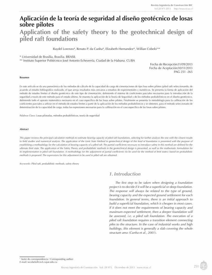
Over the past decades this phenomenon has been studied finding a new concept for foundation design, which is known as piled raft foundations (PR) (Poulos & Davis 1980). This type of analysis is applicable on deformable soils, where a superficial foundation leads to non acceptable settlements and where heavy loads demand the use of too many piles, thus significantly increasing the final cost of the foundation (Figure 1).
After the release of the technical council report TC 18 by the International Society of Mechanics and Geotechnical Engineering (ISSMGE) on 2001, an increase in the use of piled raft foundations has been observed, as they are settlement reducer elements that provide a cost effective solution. In fact, the use of such type of foundation is still reduced. The main disadvantage is the complexity generated by the load transfer mechanism between the slab and the piles. Also the difficulty arises when determining load curves versus settlements, which are mechanisms heavily influenced by the interactions between the elements integrating the foundation (slab-pile-soil) (Sales 2000). Besides, there are not design standards for the PR in many countries; consequently, the implementation of such kind of foundations has been slow for engineering projects (Ahner et al., 1997).
The safety standards currently employed at most engineering faculties follow the Limit States concepts and, they employ the Partial Coefficient standard as safety method. However, foundation design is not a generality (Quevedo 2002), by no means when dealing with deep foundations, where the global safety factor method is practically ruling all standards. Nevertheless, some of the main disadvantages of this approach are: a) it does not explicitly consider material variability; b) it works with characteristic loads, while the structure design is developed by considering design loads, that is to say the characteristic loads affected by a weighting coefficient.
In the case of PR, the definition of a global safety factor is even more complex, since the analysis involves the slab bearing capacity as well as the piles bearing capacity. Therefore, the safety analysis shall include these two elements interacting with the soil.
2. Simplified calculation methods The calculation of any foundation has two main basic
stages. The first analyzes the bearing capacity (ultimate limit state) and, the second evaluates the expected settlements (servicing state). This research studies safety within the analysis of bearing capacity, which normally rules the foundation slab design of dimensions between 6 and 14m, according to Mandolini (2003).
253Revista Ingeniería de Construcción Vol. 28 Nº3, Diciembre de 2013 www.ricuc.cl
Revista Ingeniería de Construcción RICVol 28 Nº3 2013 http://www.ricuc.cl
....................................................................................................................................................................................................................................................................................
Methods employed to assess the PR loading capacity are based on empirical correlations or based on numerical tests, which are compared to field tests. The main advantage of such methods is their simplicity. However, they are restricted as they are used only when the job site conditions are similar to the ones developed by trials or in-situ tests. A brief description of the main methods available on literature is presented below.
2.1. Kishida & Meyerhof (1965)They are the authors first proposing the PR concept on
mathematical basis. Furthermore, they developed a series of in-situ tests on piled sets, settled on sand soil, which evidenced two basic failure types for this foundation alternative (Kishida & Meyerfof 1965):
• For piles with few spaces between them, failure tendency is as a single block. It is as if piles were actually a single tube having a diameter equivalent to the addition of all piles together. In such case loading capacity is calculated based on the loading addition per equivalent tube ends and walls friction, plus the slab area not covering the piles.
• For well-spaced piles, loading capacity of the pile set is calculated as the cap loading capacity plus piles loading capacity, taking into account the overload
generated by the caps at the piles end level.
2.2 Akinmusuru (1973)This author was the first who studied the behavior of an
isolated slab, an isolated pile, and a group of piles, which end caps, are with and without contact with the soil (Cunha et al., 2001). For each case, he carried out tests intended to isolate the contribution of each pile, thus determining their influence on the interaction. By employing the results obtained from such tests, he proposed two alternatives, which are mathematically expressed by Equations 1 and 2.
Figura 1.Esquema de interacción entre elementos del sistema LPFigure 1. Elements interaction layout in the PR system
INTERACCIONES/ INTERACTIONS1: Pilote-Losa/Pile-slab2: Pilote-Pilote/Pile-Pile3: Pilote-Suelo/Pile-Soil4: Losa-Suelo/Slab-Soil
QPR=α· QPG+ß· QUR
QPR=α'· QPG+QUR
(1)
(2)
254 Revista Ingeniería de Construcción Vol. 28 Nº3, Diciembre de 2013 www.ricuc.cl
Raydel Lorenzo, Renato P. da Cunha, Elizabeth H. Zubeldia, Willian Cobelo
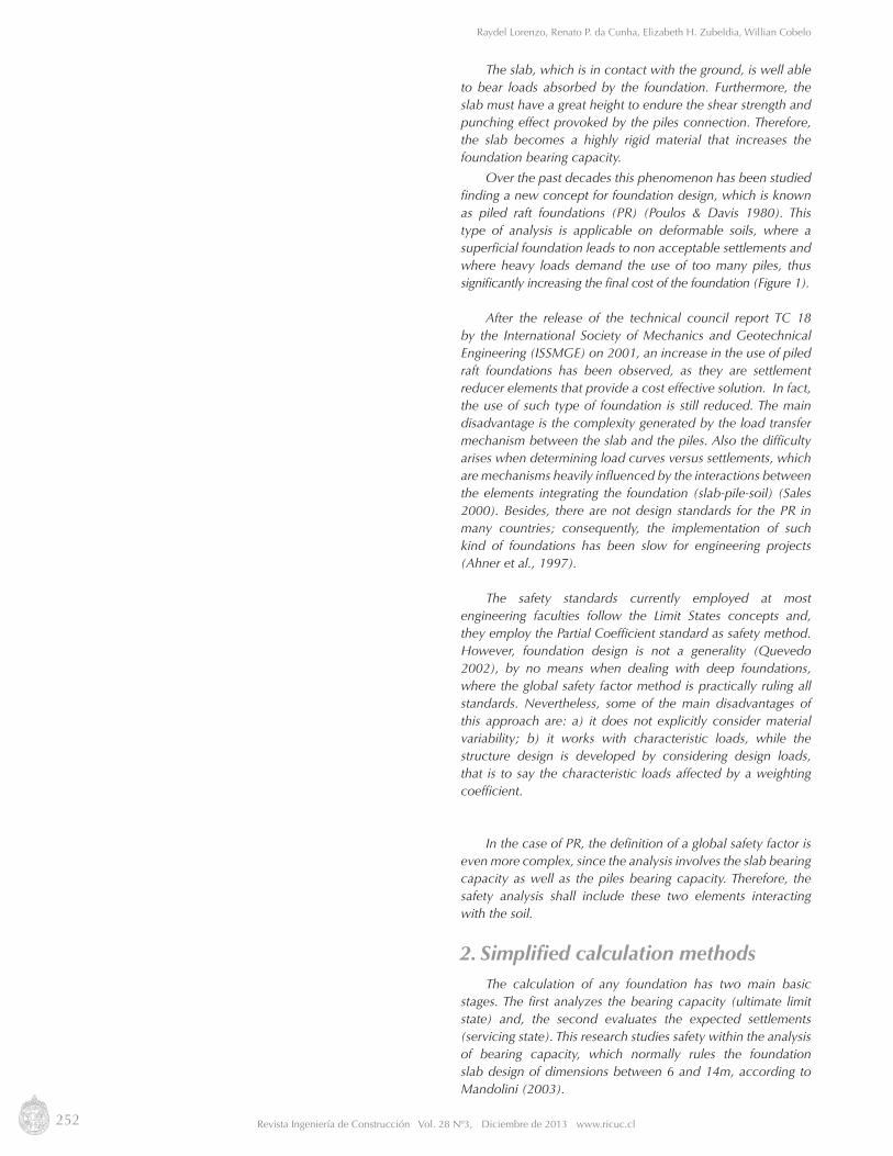
Where QPR,QUR,QPG corresponds to the PR loading capacity, the isolated foundation loading capacity and the isolated pile loading capacity, respectively. α and α’ are increase factors of loading capacity for the piles set. ß is the increase factor of the loading capacity caused by the presence of piles, which can be obtained from the graph in Figure 2.
The tests developed by Akinmusuru demonstrated that the contribution from the cap in contact with the soil is in function of its width and the piles´ length. Besides, the interaction cap-soil-pile has a greater influence on the loading capacity increase of the pile than on the slab, in other words, α >>ß. Now it is possible to write the Equation 2 by considering ß=1.
2.3 Phung (1993)This author introduced an expression (equation 3) to find
the separate contributions per cap end and per pile shaft, impacting them by a series of coefficients that consider the interactions contributions.
Where η1s and η4s are influence factors on the pile shaft loading capacity of the interaction pile-soil-pile and slab-oil-pile, respectively. η1b and η4b are influence factors on the loading capacity per end of the interaction pile-soil-pile and slab-soil-pile, respectively. QS and Qb are the loading capacity of a pile per shaft and per end, respectively. Such influence factors are obtained by employing the abacus proposed by (Phung 1993).
2.4 Sanctis&Mandolini (2006)These authors developed a numerical analysis for PR,
based on studies carried out by (Poulos & Davis 1980).
Figura 2.Factores de incremento de capacidad de carga. (Figueredo 2010)
Figure 2. Loading Capacity Increasing Factors (Figueredo 2010)
Fact
or d
e in
crem
ento
/ Inc
reas
ing
Fact
ors
α α’
y ß
Relación L/B del piloteThe pile L/B relation
(3)
255Revista Ingeniería de Construcción Vol. 28 Nº3, Diciembre de 2013 www.ricuc.cl
Revista Ingeniería de Construcción RICVol 28 Nº3 2013 http://www.ricuc.cl
....................................................................................................................................................................................................................................................................................
The latter proposed that the PR ultimate loading capacity shall be obtained from the lowest value within the following ones:
a) The ultimate loading capacity of piles in a block failure, plus the loading capacity of the slab not covering the pilesb) The addition of the slab ultimate loading capacity and the pile group as a system.
The ultimate loading capacity of a group of piles (in block); can be determined by Equation 4.
Where QBF is the loading capacity of a group of piles facing a block failure; qf is resistance per shaft; qp is resistance per end; B’ and L’ are the distances between end piles (Sanctis & Mandolini 2006).
Shaft and end resistances can be determined by employing any expression available on the literature (Tomlinson & Woodward 2008).
Equation 5 allows us to determine the failure as a system.
Where, QPR,ult,QUR,ult and QPG,ult correspond to the PR, isolated slab and piles´ ultimate loading capacities, respectively. αUR and αG are factors affecting the piles and slab ultimate loading capacities, when they are working as only one system.
So as to calculate the ultimate loading capacity of piles, the group efficiency factor shall be considered (n) as well as the number of piles (η). In this way, the loading capacity is obtained by using Equation 6.
Sanctis & Mandolini (2006) developed a parametric study based on the numeric methods analysis to find the dependency of factors αUR and αG with the geometrical characteristics of PR. Results showed that for both settlement values, 25% of pile diameter, for end resistance as well as for pile shafts were completely mobilized. Therefore, the unit value is αG(αG=1). This conclusion can be applied on all PR, as the ultimate limit state for settlement is always higher than 25% of the pile diameter.
PR numerical models were developed by generating settlements of 10% the slab width, which are considered as capable of mobilizing the whole group bearing capacity. By using the obtained points, a linear correlation was developed in order to achieve a ratio between the factor and the geometrical characteristics of the PR (ref. Figure 3 and Equation 7).
QBF=qf·2·L(L'+B')+qP·B’·L’ (4)
QPR,ult=αUR·QUR,ul+αG·QPG,ult (5)
QPG,ult=nη QP (6)
256 Revista Ingeniería de Construcción Vol. 28 Nº3, Diciembre de 2013 www.ricuc.cl
Raydel Lorenzo, Renato P. da Cunha, Elizabeth H. Zubeldia, Willian Cobelo
Where AG is the area occupied by piles, calculated by means of the end piles´ shafts. A is the slab area: s and d are spacing and piles diameter, respectively.
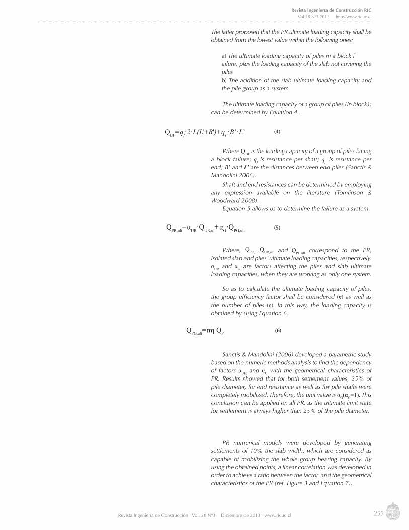
Sanctis & Mandolini (2006) defined the Area Ratio Factor FF (in accordance with Equation 8. Figure 3 shows that for a value FF = ⅓, the contribution from the slab is void αUR=0; but if FF = 0, the RP turns into foundation slab in this particular case. The factor FF allows us to define the slab efficiency, being FF = 0 the highest efficiency end and FF = ⅓ the lowest one. For example, the AG
A ~1 value represents a uniform piles´ distribution throughout the slab. With this distribution and a ratio of s
d =6 , the slab contribution achieves the 50% of its ultimate loading capacity αUR=0.5
Such simplified calculation methods on the PR ultimate loading capacity have been calibrated by means of specific soil profiles, and they shall be applied with care when conditions are different to those reported by these methods´ authors. Comparisons developed using numeric and experimental methods found on literature (Balakumar 2008, Lorenzo 2010, Figueredo 2010, Souza 2010), guarantee that the method proposed by Sanctis&Mandolini (2006) is the one obtaining the most proximate results to the actual ones.
3. Design methods
The way to introduce safety and the implementation of the Limit States Method (LSM) into the RP is quite influenced by the design philosophy to be adopted during the analysis of this type of foundation. One of the variables where the PR system operates at highest efficiency is the one that considers piles working at ultimate loading capacity (Reul & Randolph 2004). This forces us to analyze the PR safety for the whole foundation system, not by isolated elements; because piles might be working at their ultimate loading capacity but not fulfilling the safety standards established by the project regulations.
(7)αUR = 1-3·( )AG
ASd
(8)FF = ( )AG
ASd
Figura 3. Relación entre αUR y las características geométricas de la LP (Sanctis & Mandolini 2006)
Figure 3. Ratio between αUR and the geometric characteristics of PR (Sanctis & Mandolini 2006)
257Revista Ingeniería de Construcción Vol. 28 Nº3, Diciembre de 2013 www.ricuc.cl
Revista Ingeniería de Construcción RICVol 28 Nº3 2013 http://www.ricuc.cl
....................................................................................................................................................................................................................................................................................
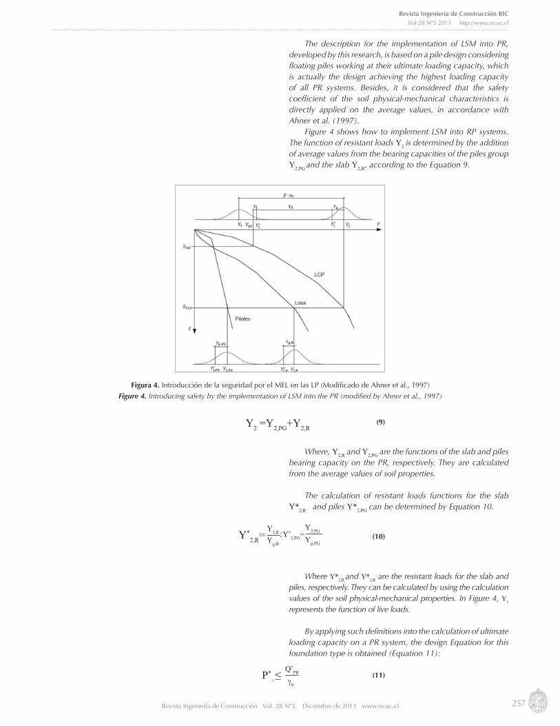
The description for the implementation of LSM into PR, developed by this research, is based on a pile design considering floating piles working at their ultimate loading capacity, which is actually the design achieving the highest loading capacity of all PR systems. Besides, it is considered that the safety coefficient of the soil physical-mechanical characteristics is directly applied on the average values, in accordance with Ahner et al. (1997).
Figure 4 shows how to implement LSM into RP systems. The function of resistant loads Y2 is determined by the addition of average values from the bearing capacities of the piles group Y2,PG and the slab Y2,R, according to the Equation 9.
Where, Y2,R and Y2,PG are the functions of the slab and piles bearing capacity on the PR, respectively. They are calculated from the average values of soil properties.
The calculation of resistant loads functions for the slab Y*2,R and piles Y*2,PG can be determined by Equation 10.
Where Y*2,R and Y*2,R are the resistant loads for the slab and piles, respectively. They can be calculated by using the calculation values of the soil physical-mechanical properties. In Figure 4, Y1
represents the function of live loads.
By applying such definitions into the calculation of ultimate loading capacity on a PR system, the design Equation for this foundation type is obtained (Equation 11):
(11)
Figura 4. Introducción de la seguridad por el MEL en las LP (Modificado de Ahner et al., 1997)
Figure 4. Introducing safety by the implementation of LSM into the PR (modified by Ahner et al., 1997)
(9)Y2 =Y2,PG+Y2,R
(10)Y*2,R=
Y2,R Y2,PG Y*
2,PG= Yg,RYg,PG
;
P*· ≤
Q*PR
γS
258 Revista Ingeniería de Construcción Vol. 28 Nº3, Diciembre de 2013 www.ricuc.cl
Raydel Lorenzo, Renato P. da Cunha, Elizabeth H. Zubeldia, Willian Cobelo
Where P* is the total vertical live load; γs is a partial coefficient that considers working conditions and the type of failure; Q*
PR is the calculated loading capacity of the PR system, which can be calculated by Equation 12.
Q*UR and Q*
PG are the loading capacities of the isolated slab and the isolated piles, respectively; which are obtained from soil properties values.
Vertical live load can be obtained by means of load weighting coefficients for loads γf,i defined by design regulations in accordance with the loading type, which are applied into the characteristic values, as per Equation 13.
Pki are the characteristic loads and γf,i are partial weighting coefficients of live loads.
The calculated physical-mechanical properties are determined applying safety coefficients γg,i on the average values obtained from the results statistical process by laboratory tests. In order to define average values it is recommended to follow the research engineering and geology guidelines on the minimum laboratory tests requested for each parameter. Calculation values are expressed by Equations 14, 15 and 16.
Where,ø, c, γ are the average values of an internal friction angle, cohesion and specific weight of the soil, respectively. ø*,c* ,γ* are the calculation values of the internal friction angle, cohesion and soil specific weight, respectively. γgtgø, γgc , γgγ are safety coefficients of the internal friction angle, cohesion and soil specific weight, respectively, determined for a probability of α = 0.95.
3.1 Application of safety theory into the PR geo-technical design Probabilistic methods enable the calculation of partial
safety coefficients to be used in the design of the Limit States Method. The application of this safety approach into the PR systems has not been adopted by design regulations yet. Therefore, loading and resistance partial coefficients have not been established so far. However, the expressions required to calibrate partial coefficients, to be employed by LSM, can be developed from the general procedure described by Quevedo (2002). This procedure has been successfully used by Quevedo (2002) in the case of superficial foundations on cohesive soils; by Gonzalez-Cueto (2000) for superficial foundations on friction soils and; by Lima (2006) for water well foundations and anchoring foundations.
(12)Q*PR = αUR·Q*
UR+Q*PG
(13)P*= Σ(Pki·γfi)
(14)
(15)
(16)
ø*= tan˗1 tanøγgtgø
c*= cγgc
γ*= γγgγ
”type” : “thesis” }, “uris” : [ “http://www.mendeley.com/documents/?uuid=452095bc-ecec-4555-9538-cb4aa1572992” ] } ], “mendeley” : { “previouslyFormattedCitation” : “(Lima 2006
259Revista Ingeniería de Construcción Vol. 28 Nº3, Diciembre de 2013 www.ricuc.cl
Revista Ingeniería de Construcción RICVol 28 Nº3 2013 http://www.ricuc.cl
....................................................................................................................................................................................................................................................................................
The calibration procedure in this methodology demands the calculation of the design global Safety Factor (Fs,design) and the required or optimal global Safety Factor (Fs,optimal). In the following sections, the procedures to be followed to obtain such values are described.
3.1.1 Design global safety factorThe function of resistant loads and their calculation values
(Y*2), for this geotechnical analysis, is obtained in a different
way than the structural analysis. As suggested by some researchers (Quevedo 2002), safety coefficients for material physical-mechanical properties are directly applied on the average values, not on the characteristic values as normally done for structural projects.
The calculated material physical-mechanical properties are obtained by Equation 17.
Where Χ*i is the value for the i-property of soil and γgi is the
safety coefficient for the i-property of the soil.Equations 18 and 19 determine the weighting coefficient
(γgi) of physical properties (specific weight) and mechanical properties (internal friction angle, cohesion), respectively.
Where tα is the value of the t-student function for α=0.95 and n-1 freedom degree; νi is the variation coefficient of the i-property of soil; ni is the amount of laboratory tests repetitions executed to achieve the i-property of soil; tα is the value of t-student function for α = 0.95 and n-2 freedom degrees.
Partial safety coefficient (γg) of resistant loads is obtained by Equation 20.
For the calculation of QPR,ult the equation achieved by Sanctis & Mandolini (2006) (Equation 5) can be used. The Q*PR is obtained from material properties by using equation 12 and by calculating the reduction coefficients of material properties employing Equations 18 and 19, or the ones indicated by design guidelines.
Weighting coefficient of live loads (γf) is calculated by Equation 21. The value tα is considered equal to 1.645, as most guidelines define the characteristic load (PK) with a 5% probability that this value may be exceeded during the structure life span.
Χ*i=
Χi
γgi(17)
(18)
(19)
(20)
γgi = 11
tα·νi
√ⁿi
γgi = 11 tα·νi
γg = QPR,ult
Q*PR
260 Revista Ingeniería de Construcción Vol. 28 Nº3, Diciembre de 2013 www.ricuc.cl
Raydel Lorenzo, Renato P. da Cunha, Elizabeth H. Zubeldia, Willian Cobelo
Finally, the design global safety coefficient Fs,diseño is obtained by Equation 22.
3.12. Optimal Safety FactorThe calculation of the Optimal Safety Factor (Fs,optimal)
involves equations, which derivative processes are more complex than the ones used for design global safety factor. The functions of live load (Y1) and resistant loads (Y2) are defined by equations 23 and 24, where P is the average value of resistant loads and QPR,ult the ultimate loading capacity of the PR system.
The required safety level (Hrequerido) is related to the Fs,optimal, for the case of PR design in Equation 25.
This expression considers a normal statistical distribution for the function safety margin (Y2˗Y1) and øn[] represents Laplace function. Further details about this expression can be found on Griffiths&Fenton (2007) and Lorenzo (2010).
Since resulting variation coefficients for live loads (νp) and ultimate loading capacity (νQPR,ult) are unknown values, it is necessary to determine them by using Equations 26 and 27.
Where σp is the standard deviation for total vertical live load and σQPR,ult is the standard deviation of the ultimate loading capacity of the PR system.
Taking into account that total load is the result of the addition of several representative values of several random variables; deviation of total vertical live load (σp) can be calculated by Equation 28.
γf=ΣPki·γfi
ΣPki(1˗tα·νi)(21)
(22)(Fs,diseño)=γf·γg·γs
Y1= P
Y2= QPR,ult
(23)
(24)
(25)
(26)
(27)
[
√
]
261Revista Ingeniería de Construcción Vol. 28 Nº3, Diciembre de 2013 www.ricuc.cl
Revista Ingeniería de Construcción RICVol 28 Nº3 2013 http://www.ricuc.cl
....................................................................................................................................................................................................................................................................................
Since loading capacity is a function depending on several random variables, the determination of deviation of the ultimate loading capacity of the PR system (σQPR,ult) is more complex than the deviation calculation of live loads. In this case, a serial Taylor development can be carried out, where the linear function and the general deviation theorem are combined (Lorenzo 2010). Consequently, deviation can be calculated by Equation 29.
Where rc·tan ø is the correlation coefficient between cohesion and the internal friction angle tangent of the soil.
Derivatives in Equation 29 are obtained from equations for loading capacities published on (CTE 2006), thus leading to Equations 30 to 35. Depth coefficients are considered as equal to the unit, in order to simplify calculations. Above does not introduce a considerable error, since the contribution of soil loading capacity over the PR foundation represents a very low percentage of total loading capacity. For granular soils and cohesive soils using drainage systems, Equations 30 to 32 can be used. Meanwhile, for cohesive soils under a short term analysis, such expressions are simplified, thus resulting Equations 33 to 35.
∑ (28)
(29)
(31)
( ) ( )
(
)
(
) (
)
(
)
[
]
[ ]
[
]
[
( )( ) ]
(32)
(33)
(34)
(35)
(30)
262 Revista Ingeniería de Construcción Vol. 28 Nº3, Diciembre de 2013 www.ricuc.cl
Raydel Lorenzo, Renato P. da Cunha, Elizabeth H. Zubeldia, Willian Cobelo
Form factor derivatives in regards to tan ø expressed in equation 30 are obtained by adjusting the form factors curve functions tan ø to polynom degree 5, as shown by Equations 36 to 38.
Deviations of random physical-mechanical parameters can be expressed by Equations 39 to 41.
In this way it is possible to calculate the variation of loading coefficient (νp) and the ultimate loading capacity (νQPR,utl), which result is used to achieve the Fs,optimal for the expected safety level value. Quevedo (2002) recommended employing the geotechnical design per ultimate limit state (H) considering a safety value of 0.98, which corresponds to a failure probability of 0.02.
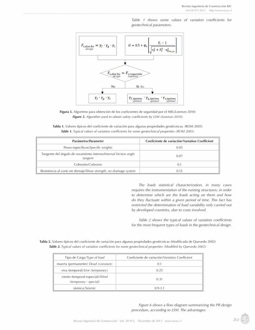
By comparing Fs,optimal and Fs,design it is possible to understand if the employed safety partial coefficients are the adequate ones. Generally, the ones employed by geotechnical design are quite conservative coefficients (Quevedo 2002), in other words, they use higher values than the ones required for guaranteeing the expected safety level. Consequently, a calibration process shall be used by decreasing safety coefficient values until reaching one or several combinations fulfilling Fs,design = Fs,optimal. In practice, loading variability has been less assessed than geotechnical parameters; therefore, it is recommended deceasing safety coefficients (γg) related to the latter parameters and keeping the ones affecting loads (γf). In this way, it is possible to use the same weighting coefficients of design loading capacities for the structure and for the foundation. Figure 5 shows the algorithm summarizing this developed proposal.
3.1.2 Variation coefficients from geotechnical parameters and loadings.
In order to develop the described procedure it is necessary to statistically characterize the random variables involved in the analyses. Therefore, from each geotechnical parameter, it will be required to define the most representative value, generally corresponding to the estimation of the average value and the possible variation range of a given parameter.
(36)
(39)
(37)
(40)
(38)
(41)
263Revista Ingeniería de Construcción Vol. 28 Nº3, Diciembre de 2013 www.ricuc.cl
Revista Ingeniería de Construcción RICVol 28 Nº3 2013 http://www.ricuc.cl
....................................................................................................................................................................................................................................................................................
Table 1 shows some values of variation coefficients for geotechnical parameters.
The loads statistical characterization, in many cases requires the instrumentation of the existing structures; in order to determine which are the loads acting on them and how do they fluctuate within a given period of time. This fact has restricted the determination of load variability only carried out by developed countries, due to costs involved.
Table 2 shows the typical values of variation coefficients for the most frequent types of loads in the geotechnical design.
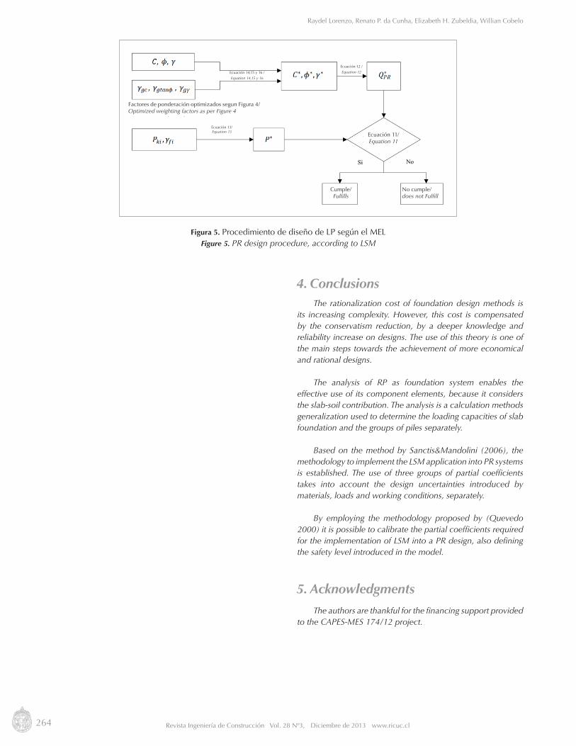
Figure 6 shows a flow diagram summarizing the PR design procedure, according to LSM. The advantages:
Figura 5. Algoritmo para obtención de los coeficientes de seguridad por el MEL(Lorenzo 2010)
Figure 5. Algorithm used to obtain safety coefficients by LSM (Lorenzo 2010)
Tabla 1. Valores típicos del coeficiente de variación para algunas propiedades geotécnicas. (ROM 2005)
Table 1. Typical values of variation coefficients for some geotechnical properties (ROM 2005)
Tabla 2. Valores típicos del coeficiente de variación para algunas propiedades geotécnicas (Modificada de Quevedo 2002)
Table 2. Typical values of variation coefficients for some geotechnical properties (Modified by Quevedo 2002)
design
design
optimal optimal optimal
/Yes
required
Parámetro/Parameter Coeficiente de variación/Variation Coefficient
Pesos específicos/Specific weights 0.05
Tangente del ángulo de rozamiento interno/Internal friction angle tangent
0.07
Cohesión/Cohesion 0.1
Resistencia al corte sin drenaje/Shear strength, no drainage system 0.15
Tipo de Carga/Type of load Coeficiente de variación/Variation Coefficient
muerta (permanente)/ Dead (constant) 0.1
viva (temporal)/Live (temporary) 0.25
viento (temporal especial)/Wind
(temporary - special)0.31
sísmica/Seismic 0.9-1.1
264 Revista Ingeniería de Construcción Vol. 28 Nº3, Diciembre de 2013 www.ricuc.cl
Raydel Lorenzo, Renato P. da Cunha, Elizabeth H. Zubeldia, Willian Cobelo
4. Conclusions The rationalization cost of foundation design methods is
its increasing complexity. However, this cost is compensated by the conservatism reduction, by a deeper knowledge and reliability increase on designs. The use of this theory is one of the main steps towards the achievement of more economical and rational designs.
The analysis of RP as foundation system enables the effective use of its component elements, because it considers the slab-soil contribution. The analysis is a calculation methods generalization used to determine the loading capacities of slab foundation and the groups of piles separately.
Based on the method by Sanctis&Mandolini (2006), the methodology to implement the LSM application into PR systems is established. The use of three groups of partial coefficients takes into account the design uncertainties introduced by materials, loads and working conditions, separately.
By employing the methodology proposed by (Quevedo 2000) it is possible to calibrate the partial coefficients required for the implementation of LSM into a PR design, also defining the safety level introduced in the model.
5. Acknowledgments
The authors are thankful for the financing support provided to the CAPES-MES 174/12 project.
Figura 5. Procedimiento de diseño de LP según el MELFigure 5. PR design procedure, according to LSM
Factores de ponderación optimizados segun Figura 4/Optimized weighting factors as per Figure 4
Ecuación 11/Equation 11
Ecuación 13/Equation 13
Ecuación 14,15 y 16 /
Equation 14,15 y 16
Ecuación 12 /
Equation 12
Cumple/Fulfills
No cumple/does not Fulfill

265Revista Ingeniería de Construcción Vol. 28 Nº3, Diciembre de 2013 www.ricuc.cl
Revista Ingeniería de Construcción RICVol 28 Nº3 2013 http://www.ricuc.cl
....................................................................................................................................................................................................................................................................................
6. Referencias/References Ahner C., Soukhov D. y König G.(1997), Reliability Aspects of Design of Combined Piled-Raft Foundations (CPRF). 2nd Symposium in
Civil Engineering, Budapest, pp.1–8.CTE (2006), Código Técnico de la Edificación. España, p.1061.Cunha R.P., Poulos H.G. y Small J.C.(2001), Investigation of design alternatives for a piled raft case history. Journal of Geotechnical and
Geoenvironmental Engineering, 27(8), pp.635–641.Figueredo S. (2010), Análisis del comportamiento de Balsas de Cimentación combinadas con Pilotes por el Método de los Elementos
Finitos en 3D. Instituto Superior Politécnico José Antonio Echeverría. CubaGonzalez-Cueto A. V.(2000), Diseño Geotécnico de Cimentaciones Superficiales en Arenas. Universidad Central de las Villas. CubaGriffiths D. V. y Fenton G. A. (2007), Probabilistic Methods in Geotechnical Engineering. SpringerWien, New York.Kishida H. y Meyerfof G. (1965), Bearing Capacity of pile groups under eccentric loads in sand. In 6th Proc. ICSMFE. Toronto, pp.
270–274.Lima R. (2006), Diseño de cimentaciones sometidas a grandes esfuerzos de momentos y/o cortantes y axiales pequeños o de succión.
Universidad Central de Las Villas. CubaLorenzo R.(2010), Diseño Geotécnico de Losas Pilotadas Bajo la Acción de Cargas Verticales. Aplicación de la Teoría de Seguridad.
Universidad Politécnica de Madrid.EspañaMandolini A. (2003), Design of piled raft foundations : practice and development. In Ghent, ed. 4th Int. Geotechnical Seminar on Deep
Foundation on Bored and Auger Piles. Rotterdam: MillPress, pp. 59–80.Phung D.L. (1993), Footing with Settlement-Reducing Piles in Non-Cohesive Soil. PhD. Thesis, Dep. de Ingeniería Geotecnica, Chalmer
Univ. of Technology, Sweden.Poulos H.G. y Davis E.H. (1980), Pile Foundation Analysis and Design T. W. Lambe, ed., Rainbow-Bridge Book Co.Quevedo G. (2002), Aplicación de los Estados Límites y la Teoria de Seguridad en el Diseño Geotecnico en Cuba. Universidad Central
“Marta Abreu” de Las Villas. CubaReul O. y Randolph M.F. (2004), Design Strategies for Pile Rafts Subjected to Nonuniform Vertical Loading. Jounal of Geotechnical and
Geoenvironmental Engineering, 130(1), p.13.ROM(2005), Recomendaciones para Obras Marítimas 0.5.España.Sales M. M.(2000), Análise do Comportamento de Sapatas Estaqueadas. UNIVERSIDADE DE BRASÍLIA. Brasil.Sanctis L. y Mandolini A. (2006), Bearing Capacity of Piled Rafts on Soft Clay Soils. Journal of Geotechnical and Geoenvironmental
Engineering, 132(12), p.11.Souza R.S. (2010), Análise dos fatores de interação entre estacas em radier estaqueado: comparação de duas ferramentas numéricas.
Universidad de Goiás, Escola de Engenharia, Brasil.Tomlinson M. y Woodward J. (2008), Pile Design and Constructions Practice 5th. ed., London: Taylor & Francis.