Recuperar Programas Basados en Texto
4
ni.com/students/learnlabview T ext-Based Integration: Step by Step Procedure T o illustrate the needs for text-based integration in LabVIEW , consider an equation used to convert the resistance of a thermistor to the appropriate temperature in degrees Celsius. Figure 1. Formula Used to Convert Resistance of a Thermistor to T emperature You can see that this is a complex polynomial equation that requires many mathematical operations. While possible, this is something that can quickly become cluttered in LabVIEW and difficult to follow as seen in Figure 2: Figure 2. Native LabVIEW Functions for Thermistor Formula Figure 3 is an example of how the formula could be represented in a traditional text-based language such as C. This is a lot easier to u nderstand, and it resembles closely the actual equation. Now look at how to implement this using the Formula Node and MathScript Node. Figure 3. T ext-Based Code Representation of Thermistor Formula
Transcript of Recuperar Programas Basados en Texto

8/13/2019 Recuperar Programas Basados en Texto
http://slidepdf.com/reader/full/recuperar-programas-basados-en-texto 1/4
ni.com/students/learnlabview
Text-Based Integration: Step by Step Procedure
To illustrate the needs for text-based integration in LabVIEW, consider an equation used to convert theresistance of a thermistor to the appropriate temperature in degrees Celsius.
Figure 1. Formula Used to Convert Resistance of a Thermistor to Temperature
You can see that this is a complex polynomial equation that requires many mathematical operations. Whilepossible, this is something that can quickly become cluttered in LabVIEW and difcult to follow as seen inFigure 2 :
Figure 2. Native LabVIEW Functions for Thermistor Formula
Figure 3 is an example of how the formula could be represented in a traditional text-based language such
as C. This is a lot easier to understand, and it resembles closely the actual equation. Now look at how toimplement this using the Formula Node and MathScript Node.
Figure 3. Text-Based Code Representation of Thermistor Formula

8/13/2019 Recuperar Programas Basados en Texto
http://slidepdf.com/reader/full/recuperar-programas-basados-en-texto 2/4
ni.com/students/learnlabview
LabVIEW Formula NodeBefore starting this procedure, you need to complete the exercise and use the solution in the Taking aMeasurement module. You can also create a numeric control to simulate the data acquisition input.
Note: If you are not using a DAQ Assistant to acquire resistance data and convert to temperature, skip aheadto step 2 and use a numeric control in place of the DAQ Assistant.
1. Congure the voltage input DAQ Assistant to the input resistance from the digital multimeter (DMM)
terminals a. Double-click the existing DAQ Assistant to edit the conguration
b. Right-click the Voltage channel in the Channel Settings list box and select Remove from Task
c. Click the blue plus (+) sign to add a channel to the task and select Resistance
d. Select Dev1 (NI myDAQ) >> dmm
e. Ensure I ex Source is set to Internal
f. Ensure Acquisition Mode is set to 1 Sample (On Demand)
g. Press OK to apply settings
2. Place a Formula Node on the block diagram to convert resistance to degrees Celsius
a. Right-click the block diagram and select Mathematics >> Scripts & Formulas >> Formula Node b. Paste the following equation into the Formula Node window and resize accordingly
oat64 M;
M=ln(R/10000);
T=(1/(A+B*M+C*M*M+D*M*M*M))–273.15;
3. Add inputs to the Formula Node for all input variables in the equation
a. Right-click the left border and select Add Input
b. Enter R0 to relate the input to the R0 variable in the equation
c. Repeat this procedure for A, B, C, and D d. Right-click inputs A, B, C, D, and R0 and select Create >> Contro l
e. A=0.0039083; B=5.775E-7; C=1.63214E-6; D=7.1922E-8; R0=1000
f. Wire the Data output from the DAQ Assistant to the R input of the Formula Node
4. Add output for Temperature (C) to display on the chart indicator
a. Right-click the border and select Add Output
b. Enter T to relate the output to the T variable in the equation
c. Wire this output to the input of the graph indicator
5. Add a While Loop to run the VI continuously a. Right-click the block diagram and select Programming >> Structures >> While Loop
b. Left-click and drag to encompass all of the code
c. Right-click the conditional terminal and select Create >> Control
8/13/2019 Recuperar Programas Basados en Texto
http://slidepdf.com/reader/full/recuperar-programas-basados-en-texto 3/4
ni.com/students/learnlabview
6. Create the stop condition to include when the Stop button is pressed or an error is detected
a. Unwire the Conditional Terminal from the Stopped output terminal of the analog input DAQ Assistant
b. Right-click the block diagram and select Programming >> Boolean >> Or
c. Wire the output from the Stop button control to the bottom input of the Or Boolean function
d. Right-click the block diagram and select Programming >> Cluster, Class, & Variant >> Unbundle byName and place this to the right of the analog input DAQ Assistant
e. Wire the Error Out output terminal of the analog input DAQ Assistant to the input of the Unbundle by
Name function and ensure Status is selected to be unbundled f. Wire the output of the Unbundle by Name function to the top input of the Or function
g. Wire the output of the Or function to the input of the Conditional Terminal
7. Run the VI and observe the result
Get more help with the Formula Node and obtain a list of Formula Node Functions.
MathScript NodeYou can also use the MathScript Node to run preexisting .m le scripts as well as develop .m les in LabVIEW
for signal processing.Before starting this procedure, you need to complete the exercise and use the solution in the Taking aMeasurement module. You can also create a numeric control to simulate the data acquisition input.
Note: If you are not using a DAQ Assistant to acquire resistance data and convert to temperature, skip aheadto step 2 and use a numeric control in place of the DAQ assistant.
1. Congure the voltage input DAQ Assistant to the input resistance from the DMM terminals
a. Double-click the existing DAQ Assistant to edit the conguration
b. Right-click the Voltage channel in the Channel Settings list box and select Remove from Task
c. Click the blue plus (+) sign to add a channel to the task and select Resistance
d. Select Dev1 (NI myDAQ) >> dmm
e. Ensure Iex Source is set to I nternal
f. Ensure Acquisition Mode is set to 1 Sample (On Demand)
g. Press OK to apply settings
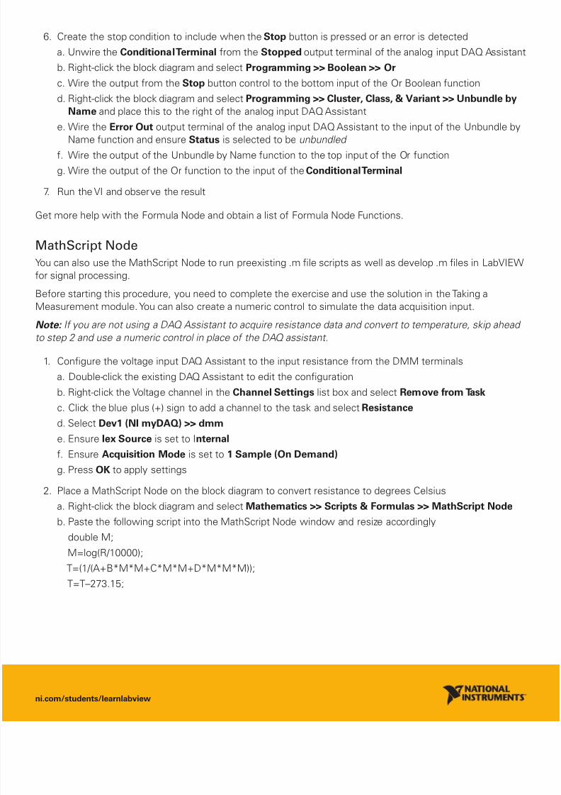
2. Place a MathScript Node on the block diagram to convert resistance to degrees Celsius
a. Right-click the block diagram and select Mathematics >> Scripts & Formulas >> MathScript Node
b. Paste the following script into the MathScript Node window and resize accordingly
double M;
M=log(R/10000); T=(1/(A+B*M*M+C*M*M+D*M*M*M));
T=T–273.15;

8/13/2019 Recuperar Programas Basados en Texto
http://slidepdf.com/reader/full/recuperar-programas-basados-en-texto 4/4
ni.com/students/learnlabview
National Instruments. All rights reserved. LabVIEW, National Instruments, NI, and ni.com are trademarks of National Instruments.roduct and company names listed are trademarks or trade names of their respective companies.
3. Add inputs to the Formula Node for all input variables in the equation
a. Right-click the left border and select Add Input
b. Enter R to relate the input to the R variable in the equation
c. Wire the Data output from the DAQ Assistant to the R input of the MathScript Node
d. Repeat for variables A, B, C, and D
e. Right-click inputs A, B, C, D, and R0 and select Create >> Control f. A=0.0039083; B=5.775E-7; C=1.63214E-6; D=7.1922E-8; R0=1000
g. Wire the Data output from the DAQ Assistant to the R input of the MathScript Node
4. Add output for Temperature (C) to display on the chart indicator
a. Right-click the border and select Add Output
b. Enter T to relate the output to the T variable in the equation
c. Wire this output to the input of the graph indicator
5. Add a While Loop to run the VI continuously
a. Right-click the block diagram and select Programming >> Structures >> While Loop
b. Left-click and drag to encompass all of the code
c. Right-click the conditional terminal and select Create >> Control
6. Create the stop condition to include when the Stop button is pressed or an error is detected
a. Unwire the Conditional Terminal from the Stopped output terminal of the analog input DAQ Assistant
b. Right-click the block diagram and select Programming >> Boolean >> Or
c. Wire the output from the Stop button control to the bottom input of the Or Boolean function
d. Right-click the block diagram and select Programming >> Cluster, Class, & Variant >> Unbundle byName and place this to the right of the analog input DAQ Assistant
e. Wire the Error Out output terminal of the analog input DAQ Assistant to the input of the Unbundle byName function and ensure Status is selected to be unbundled
f. Wire the output of the Unbundle by Name function to the top input of the Or function g. Wire the output of the Or function to the input of the Conditional Terminal
7. Run the VI and observe the result
Get more help with the LabVIEW MathScript RT Module.
You can convert your DAQ Assistant Express VIs into low-level NI-DAQmx functions by right-clicking the DAQAssistant and selecting Generate NI-DAQmx Code . The low-level NI-DAQmx API exposes more functionalityand customization options for programming.