Recovery Presentation - FRR
69
Auburn University Project “Wall-Eagle” FRR
Transcript of Recovery Presentation - FRR
Auburn UniversityProject “Wall-Eagle”FRR

Rocket Design

Rocket Model

Mass Estimates
Booster Section Upper Section
ComponentMass(lb.) Estimated
Mass(lb.) Actual Component Mass(lb.) Estimated
Mass(lb.) Actual
Structure 3.21 2.119 Structure 3.83 1.625
Ballast Tank 2.754 1.23 Payload Bay 3.07 1.5
Bulkhead 0.233 .119 Avionics Bay 2.754 1.25
Engine Block 0.315 .687 Recovery 0.296 1.824
Centering Ring 0.318 0.237 Nose Cone 2.13 2.5
Fins 0.907 1.199 Electronics 1.4 0.523
Recovery 2.22 1.708 Motor block 0.686
Motor 3.85 3.85
Electronics 0.1Total 16.527 Total 13.48 9.908
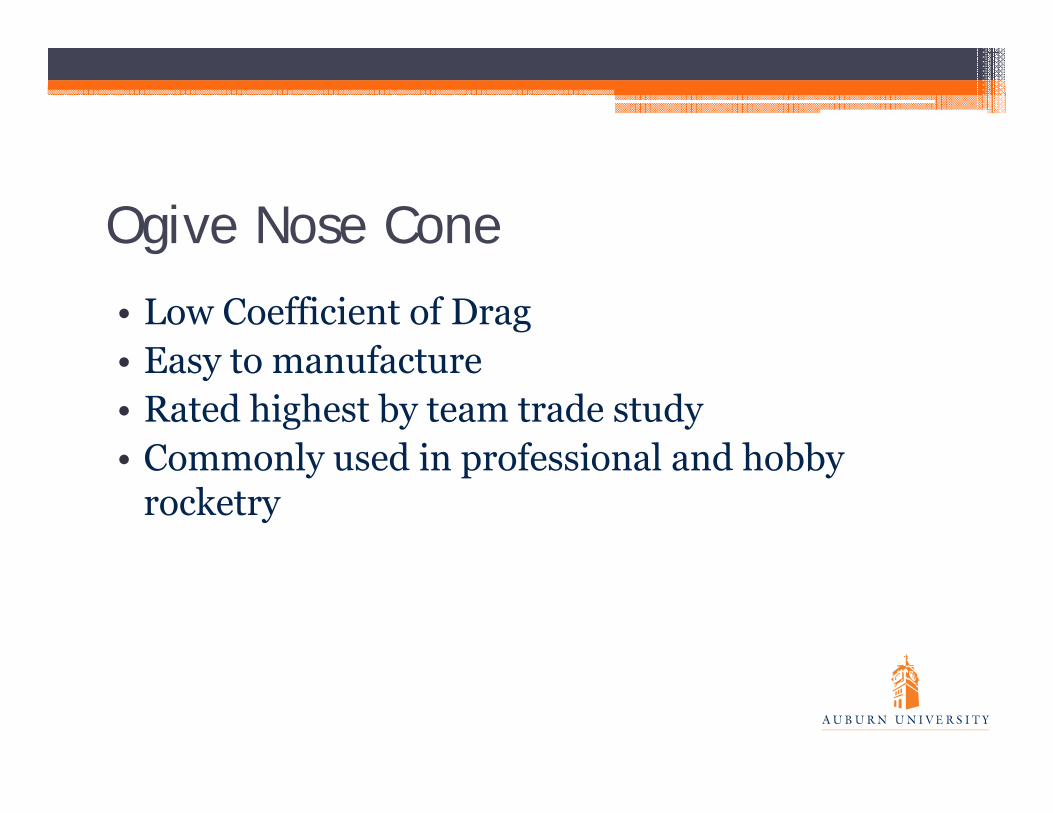
Ogive Nose Cone• Low Coefficient of Drag • Easy to manufacture • Rated highest by team trade study• Commonly used in professional and hobby
rocketry
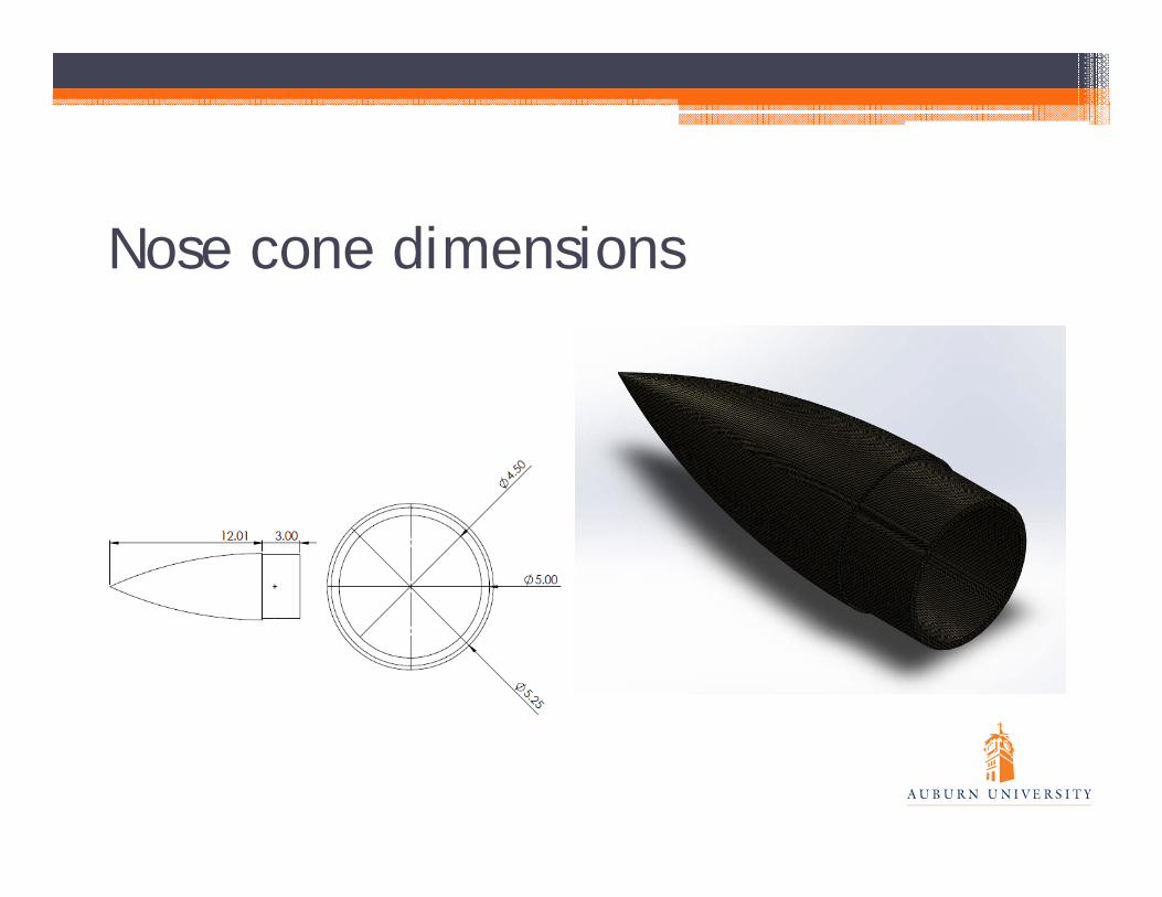
Nose cone dimensions

Trapezoidal Fin• Very easy to manufacture• Less drag than clipped delta fins, more than
elliptical fins• Quicker stabilization than elliptical fins and
clipped delta fins.

Fin Dimensions

Internal bays
• Payload Bay• Ballast Tank• Avionics Bay• Motor Section

Stability• Center of Gravity: 49.22 inches from nose tip• Center of Pressure: 61.26 inches from nose tip• Stability: 2.29 calibers• Calculations given from OpenRocket• Mass additions are expected to be added forward
of CG

Stability margin before apogee
0
0.5
1
1.5
2
2.5
3
3.5
0 2 4 6 8 10 12 14 16
Stab
ility
Cal
iber
Time (seconds)

Testing• Material testing for:▫ Carbon Fiber▫ ABS Plastic
• Ground testing▫ Co2 system▫ Igniter ▫ AGSE clearance
• Wind Tunnel▫ Payload bay door▫ Parachutes

Motor Selection

Motor Selection / Altitude Prediction
• Initial Motor selection is the Aero K960-P▫ R-P: Loki White, Plugged
• Initial thrust-to-weight ratio above required 5:1• Achieves above average thrust within ¼ second• High initial thrust provides high stability off the
rail• Rail exit velocity is 75 ft/s
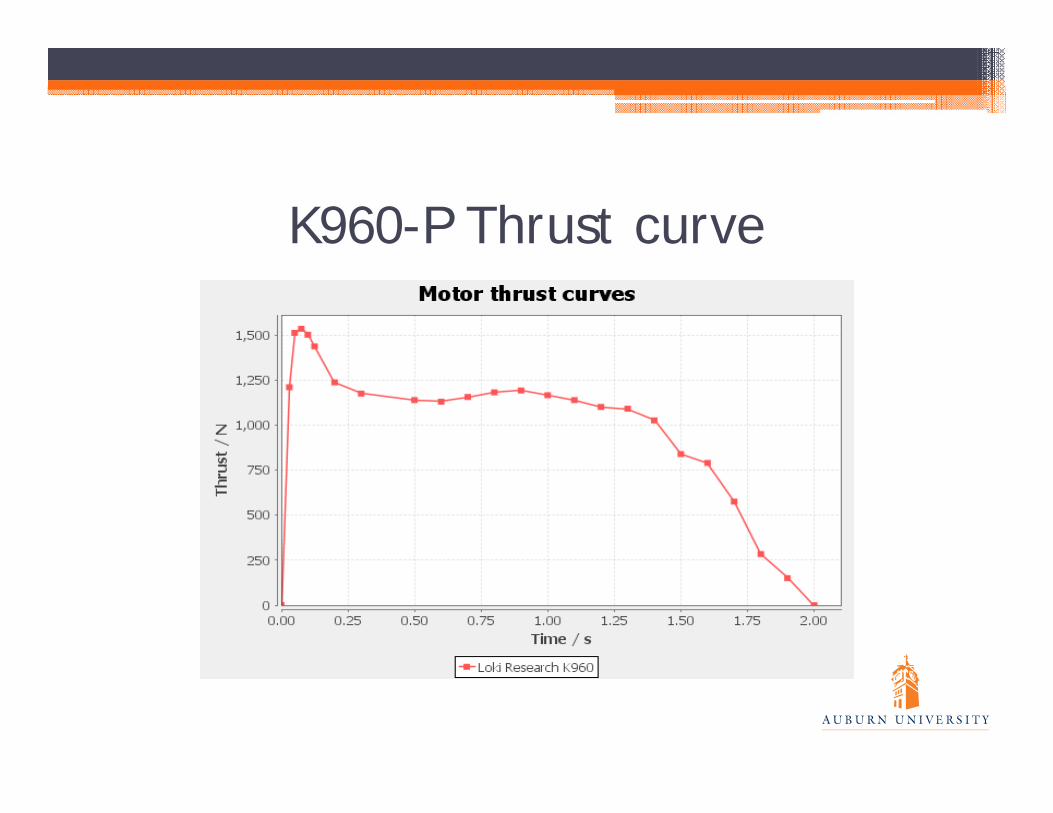
K960-P Thrust curve
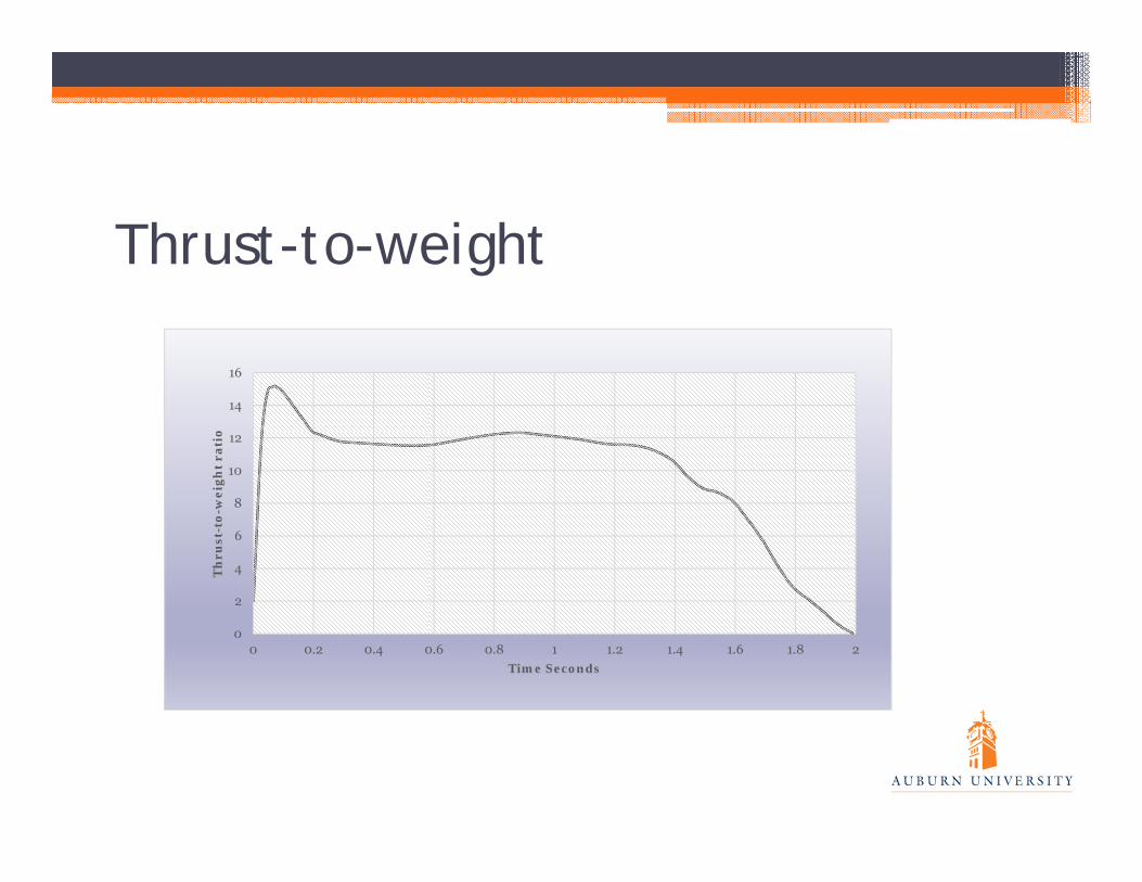
Thrust-to-weight
0
2
4
6
8
10
12
14
16
0 0.2 0.4 0.6 0.8 1 1.2 1.4 1.6 1.8 2
Th
rust
-to-
wei
ght r
atio
Time Seconds

Altitude Predictions• At 5 Mph winds expected altitude of 2958 ft• At 10 Mph winds expected altitude of 2927ft• At 15 Mph winds expected altitude of 2898ft• At 20 Mph winds expected altitude of 2885ft• Mass can easily be removed from ballast • Kinetic Energy at main deploy is 23373 lb-ft• Kinetic energy upon landing is 5511 lb-ft

K960-P Altitude vs. TimeFigure 1.3: Altitude vs. Time K780R-P
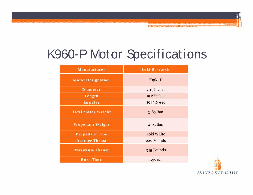
K960-P Motor SpecificationsManufacturer Loki Research
Motor Designation K960-P
Diameter 2.13 inches
Length 19.6 inches
Impulse 1949 N-sec
Total Motor Weight 3.85 lbm
Propellant Weight 2.05 lbm
Propellant Type Loki White
Average Thrust 225 Pounds
Maximum Thrust 345 Pounds
Burn Time 1.95 sec
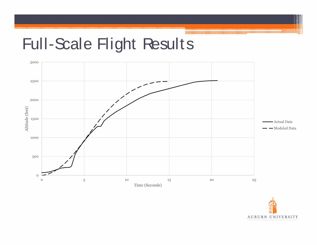
Full-Scale Flight Results
0
500
1000
1500
2000
2500
3000
0 5 10 15 20 25
Alt
itud
e (f
eet)
Time (Seconds)
Actual Data
Modeled Data

Full-Scale Successes and Failures• Modeling Predictions — Highly Accurate▫ Predicted – 2487, Actual - 2511
• Stability — Very Stable• Recovery — Main deploy failure, but CO2
Ejection System Overall Success

Recovery

Overview

Parachutes▫ Drogue – 22 inches▫ Deploys at apogee ▫ Slows rocket components to safe speed for main deploy
▫ Main – 99 inches▫ Recovers booster section and avionics bay
▫ Payload – 65 inches▫ Deploys simultaneously with main▫ Recovers payload bay and attached nose cone

Parachutes• Construction▫ Shape Semi-ellipsoidal No spill hole

Electronics▫ Redundant altimeters Altus Metrum Telemetrum PerfectFlite StratoLogger
▫ RF trackers▫ ZigBee mini GPS

Attachments• Fasteners▫ Nylon Slotted Pan Head Machine Screws▫ Steel U-Bolts▫ Quick Links
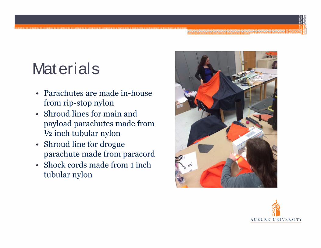
Materials• Parachutes are made in-house
from rip-stop nylon• Shroud lines for main and
payload parachutes made from ½ inch tubular nylon
• Shroud line for drogue parachute made from paracord
• Shock cords made from 1 inch tubular nylon

CO2 Ejection System• Increased safety• More reliable at high altitudes• Reduced risk of equipment damage
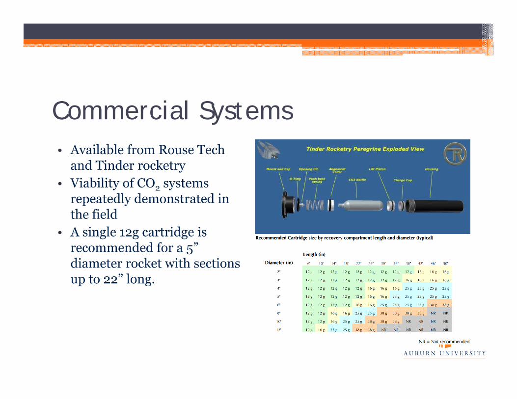
Commercial Systems• Available from Rouse Tech
and Tinder rocketry• Viability of CO2 systems
repeatedly demonstrated in the field
• A single 12g cartridge is recommended for a 5” diameter rocket with sections up to 22” long.
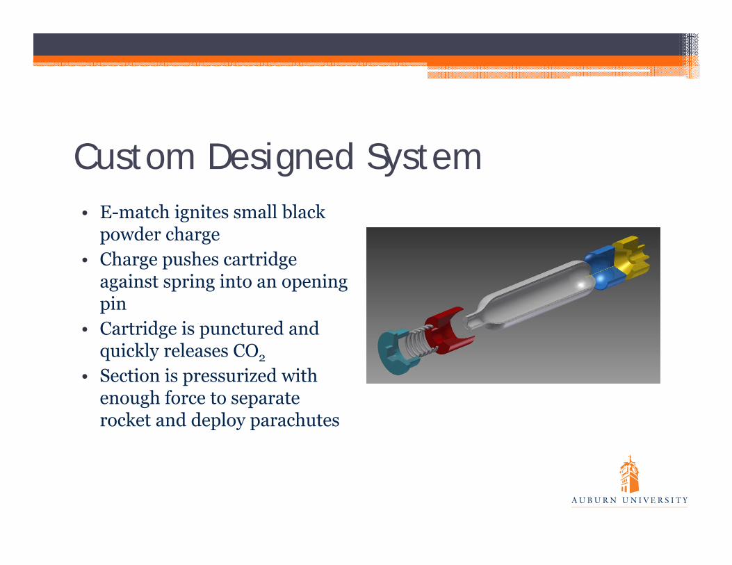
Custom Designed System• E-match ignites small black
powder charge• Charge pushes cartridge
against spring into an opening pin
• Cartridge is punctured and quickly releases CO2
• Section is pressurized with enough force to separate rocket and deploy parachutes

Custom Designed System• Each system contains three CO2 cartridges• Each cartridge is separately controlled

Ejection System Implementation• Two ejection systems total mounted outside the avionics bay• One ejection system deploys drogue parachute • Second system deploys main parachute and ejects payload
bay• Each altimeter controls all charges on both ejection systems

Drift Calculations
Section Weight
(lbs.)
Parachute
Size (ft.) 5 mph 10 mph 15 mph 20 mph
Booster section and avionics bay (main parachute)
14.3 lbs. 8.25 ft. 1096 ft. 1228 ft. 1315 ft. 1476 ft.
Payload bay and nose cone (payload parachute)
4.9 lbs. 5.42 ft. 874 ft. 973 ft. 1038 ft. 1159 ft.

Autonomous Ground Support Equipment – Project WALL-Eagle

Overall Final Design

AGSE Design Overview

AGSE Payload Bay and Hatch
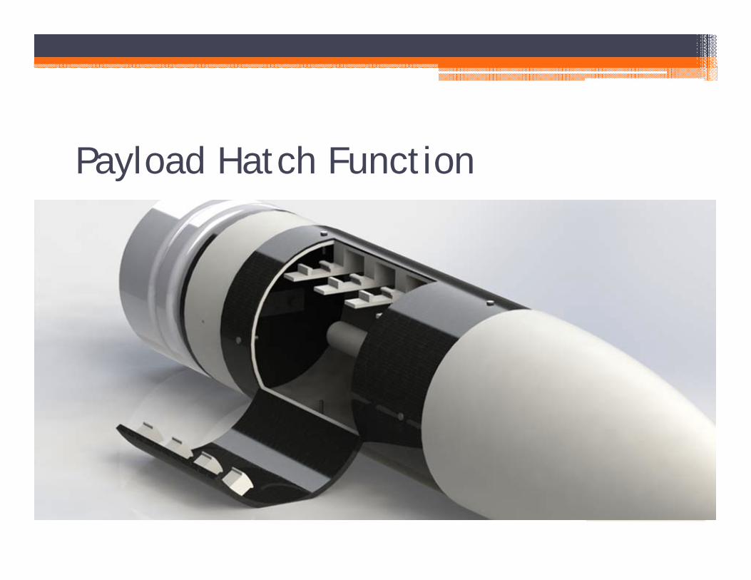
Payload Hatch Function

Payload Access Plate and Positioning

Payload Bay Drawing

Payload Retrieval System (PRS)

• ~29” maximum reach(nearly 7-inch extension)• 5 degrees of freedom• Most value and capabilities
for the price• Completely customizable• Price - $830• Infrared sensors installed• Modified gripper
Modified CrustCrawler AX-12A Smart Robotic Arm
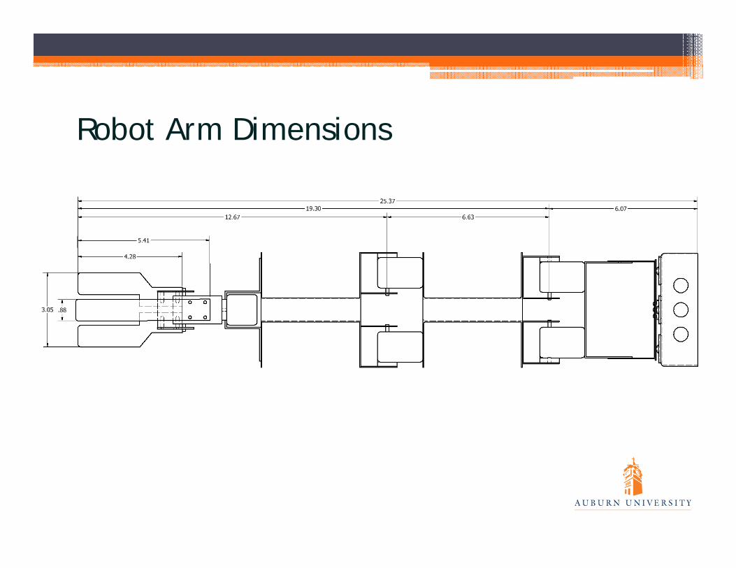
Robot Arm Dimensions

Robot Arm Gripper

Modified Robot Arm
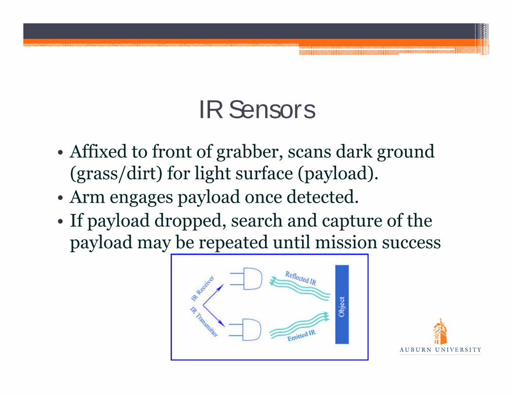
IR Sensors• Affixed to front of grabber, scans dark ground
(grass/dirt) for light surface (payload).• Arm engages payload once detected.• If payload dropped, search and capture of the
payload may be repeated until mission success
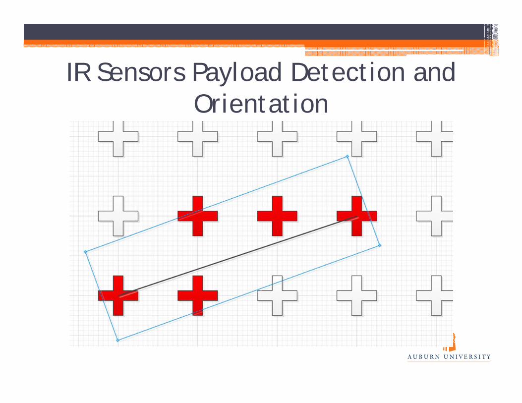
IR Sensors Payload Detection and Orientation

Contingency: Preprogrammed Location
• Use preprogrammed location of payload in case IR sensors plan doesn’t work out
• Can choose location of payload, so static coordinates suffice
• Easier, but will cause launch failure if payload dropped

Launch Vehicle Elevation System (LVE)

LVE Drawing

LVE Drawing

LVE LT 2000 Winch

Elevation Sequence• Measurements ensure bottom
does not contact the ground• Rocket attached to truss via
slotted launch rail• Truss will be cued to stop via
pressure switch• Truss will lock in vertical
position once erect via winch system and blast plate
• Expected to take approximate 60 seconds or less
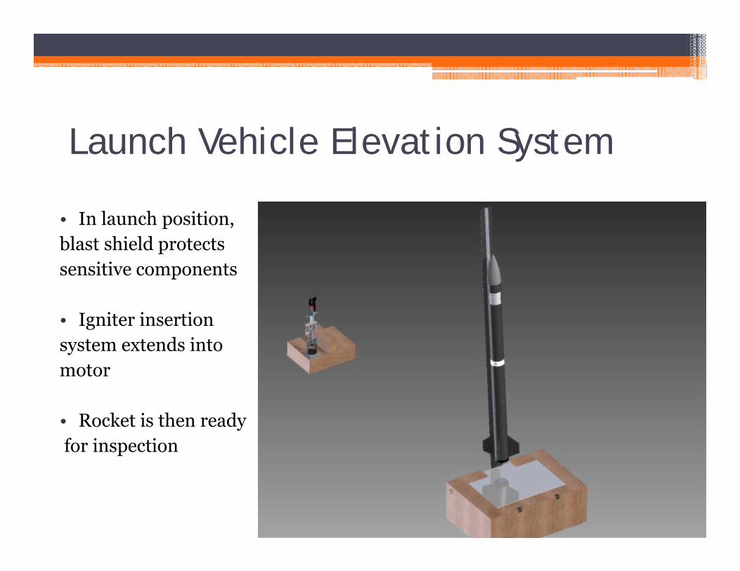
Launch Vehicle Elevation System
• In launch position, blast shield protects sensitive components
• Igniter insertion system extends into motor
• Rocket is then readyfor inspection

Automated Charge Insertion System (ACI)

Igniter Insertion System• Toothed insertion
system• DC electric motor drives
the tooth extender into the mast
• Initiated with a program that is linked to the AGSE controller
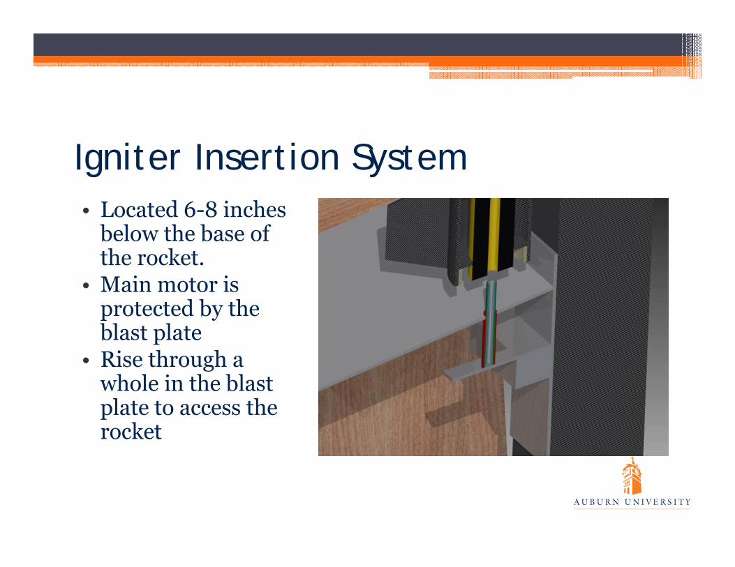
Igniter Insertion System• Located 6-8 inches
below the base of the rocket.
• Main motor is protected by the blast plate
• Rise through a whole in the blast plate to access the rocket

Igniter Insertion System• Extension of 26.6
inches• Igniter pause at full
extension • E-match attached to tip
of the insertion system is in contact with motor
• Inspection and arming of the rocket
• Countdown ensues, followed by blast off
• Dowel diameter will not choke motor

Master Microcontroller and Full System Operation
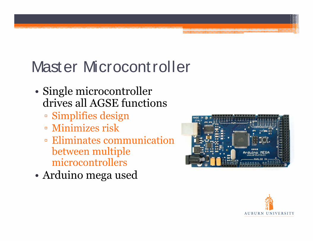
Master Microcontroller• Single microcontroller
drives all AGSE functions▫ Simplifies design▫ Minimizes risk▫ Eliminates communication
between multiple microcontrollers
• Arduino mega used

Electrical Schematic for AGSE
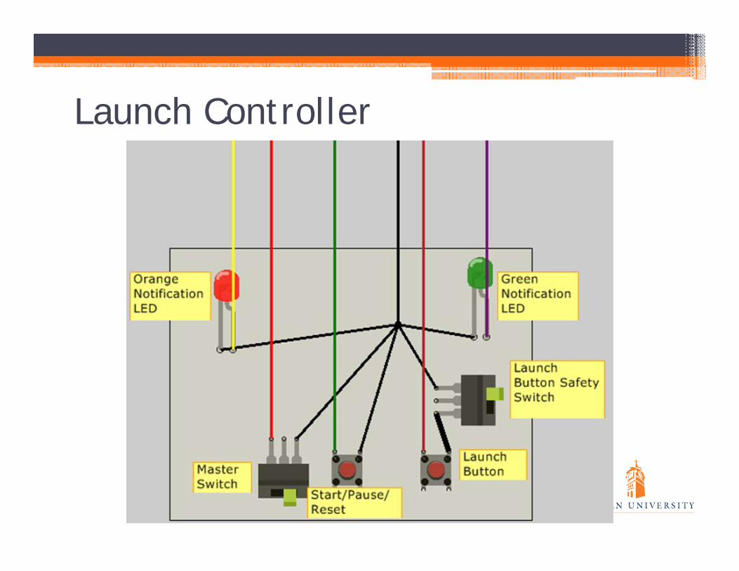
Launch Controller

Subsystem Connectivity• All autonomous
systems connected through microcontroller▫ Only launch
controller handled independently
• Single start, pause, and reset switches

Systems Sequence Test
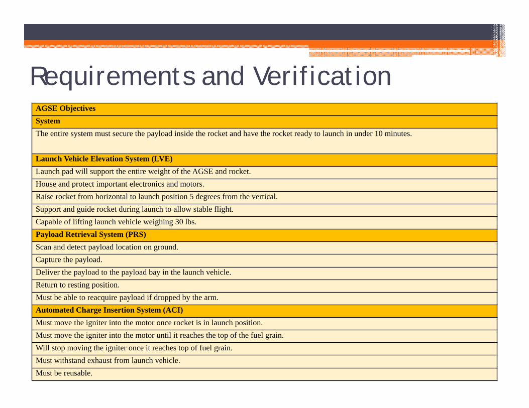
Requirements and VerificationAGSE ObjectivesSystemThe entire system must secure the payload inside the rocket and have the rocket ready to launch in under 10 minutes.
Launch Vehicle Elevation System (LVE)Launch pad will support the entire weight of the AGSE and rocket.House and protect important electronics and motors.Raise rocket from horizontal to launch position 5 degrees from the vertical.Support and guide rocket during launch to allow stable flight.Capable of lifting launch vehicle weighing 30 lbs.Payload Retrieval System (PRS)Scan and detect payload location on ground.Capture the payload.Deliver the payload to the payload bay in the launch vehicle.Return to resting position.Must be able to reacquire payload if dropped by the arm.Automated Charge Insertion System (ACI)Must move the igniter into the motor once rocket is in launch position.Must move the igniter into the motor until it reaches the top of the fuel grain.Will stop moving the igniter once it reaches top of fuel grain.Must withstand exhaust from launch vehicle.Must be reusable.

Project Management
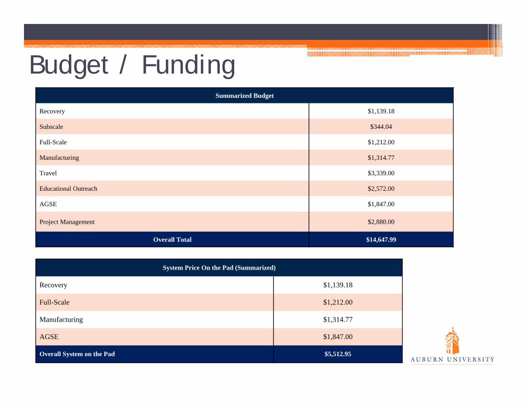
Budget / FundingSummarized Budget
Recovery $1,139.18
Subscale $344.04
Full-Scale $1,212.00
Manufacturing $1,314.77
Travel $3,339.00
Educational Outreach $2,572.00
AGSE $1,847.00
Project Management $2,880.00
Overall Total $14,647.99
System Price On the Pad (Summarized)
Recovery $1,139.18
Full-Scale $1,212.00
Manufacturing $1,314.77
AGSE $1,847.00
Overall System on the Pad $5,512.95
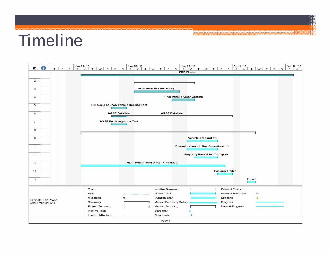
Timeline


![[FRR] No Dispares Al Mensajero Por Sean Kennedy Completo](https://static.fdocuments.ec/doc/165x107/5571ff2949795991699cc12e/frr-no-dispares-al-mensajero-por-sean-kennedy-completo.jpg)