Protección de sobrecorriente y coordinación de la protección · PDF...
18
•http://en.wikipedia.org/wiki/Circuit_breaker •http://hyperphysics.phy-astr.gsu.edu/hbase/electric/bregnd.html •http://www.memonline.com/guide05.html •http://www.bussmann.com/library/techspec/TechSpec19.pdf •www.bussmann.com/library/ topics/EDP_2%20P%2014-22%20Example.pdf •http://www.geindustrial.com/solutions/engineers/time_current_curves.html •http://www.cutler-hammer.eaton.com/unsecure/html/101basics/Module05/Output/ •http://www.sea.siemens.com/step/pdfs/mccb_1.pdf •http://www.sea.siemens.com/step/pdfs/mccb_2.pdf •http://www.sea.siemens.com/step/pdfs/mccb_3.pdf •http://www.sea.siemens.com/step/pdfs/mccb_4.pdf •http://www.sandc.com/webzine/111102_1.asp Protección de sobrecorriente y coordinación de la protección Elaborado por : Jesús Baez Revisión : Octubre,2007 Referencias Electrónicas
Transcript of Protección de sobrecorriente y coordinación de la protección · PDF...
•http://en.wikipedia.org/wiki/Circuit_breaker
•http://hyperphysics.phy-astr.gsu.edu/hbase/electric/bregnd.html
•http://www.memonline.com/guide05.html
•http://www.bussmann.com/library/techspec/TechSpec19.pdf
•www.bussmann.com/library/ topics/EDP_2%20P%2014-22%20Example.pdf
•http://www.geindustrial.com/solutions/engineers/time_current_curves.html
•http://www.cutler-hammer.eaton.com/unsecure/html/101basics/Module05/Output/
•http://www.sea.siemens.com/step/pdfs/mccb_1.pdf
•http://www.sea.siemens.com/step/pdfs/mccb_2.pdf
•http://www.sea.siemens.com/step/pdfs/mccb_3.pdf
•http://www.sea.siemens.com/step/pdfs/mccb_4.pdf
•http://www.sandc.com/webzine/111102_1.asp
Protección de sobrecorriente y coordinación de la protección
Elaborado por : Jesús Baez Revisión : Octubre,2007
Referencias Electrónicas

Protección de conductoresReferencia http://www.bussmann.com/library/techspec/TechSpec19.pdf

Referencia: www.bussmann.com/library/ topics/EDP_2%20P%2014-22%20Example.pdf

Coordinación de las protecciones
Coordinación incorrecta Coordinación correcta
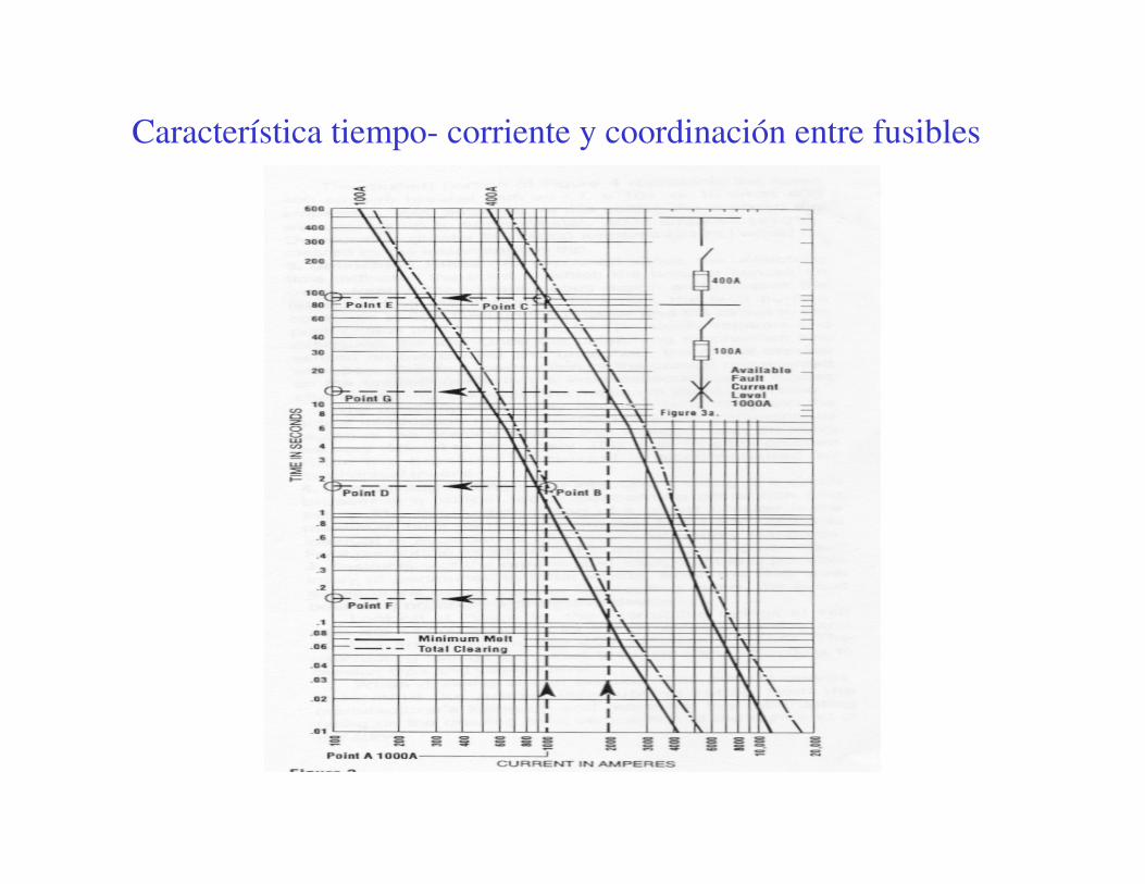
Característica tiempo- corriente y coordinación entre fusibles

Coordinación entre interruptores

Capacidad interruptiva
Referencia:http://www.sea.siemens.com/step/pdfs/mccb_2.pdf
Alternativa 1: Todos los elementos
con la misma capacidad interruptiva, la cual
Debe ser mayor o igual que el nivel de corto
Circuito disponible
Alternativa 2: Interruptor “aguas arriba” debe tener
Una capacidad interruptiva mayor o igual que el nivel
de corto circuito disponible en el sistema, pero los
Interruptores “aguas abajo” pueden tener capacidades
Interruptivas inferiores
“The second method is to select circuit breakers with a series
combination rating equal to or greater than the available fault
current at the service entrance. The series-rated concept is that
the main upstream breaker must have an interrupting rating
equal to or greater than the available fault current of the system,
but subsequent downstream breakers connected in series can
be rated at lower values. For example, a building with 65,000
amperes of available fault current might only need the breaker
at the service entrance to be rated at 65,000 AIC. Additional
downstream breakers can be rated at lower values. The series
combination must be tested and listed by UL.”
“The first method is to select circuit breakers with individual
ratings equal to or greater than the available fault current.
This means that, in the case of a building with 65,000
amperes of fault current available at the service entrance,
every circuit breaker must be rated at 65,000 amperes
interrupting capacity (AIC).”
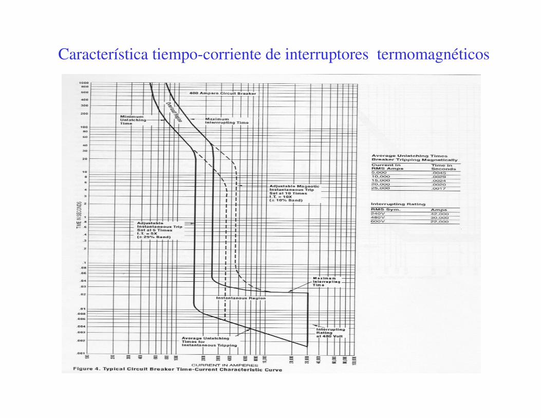
Característica tiempo-corriente de interruptores termomagnéticos
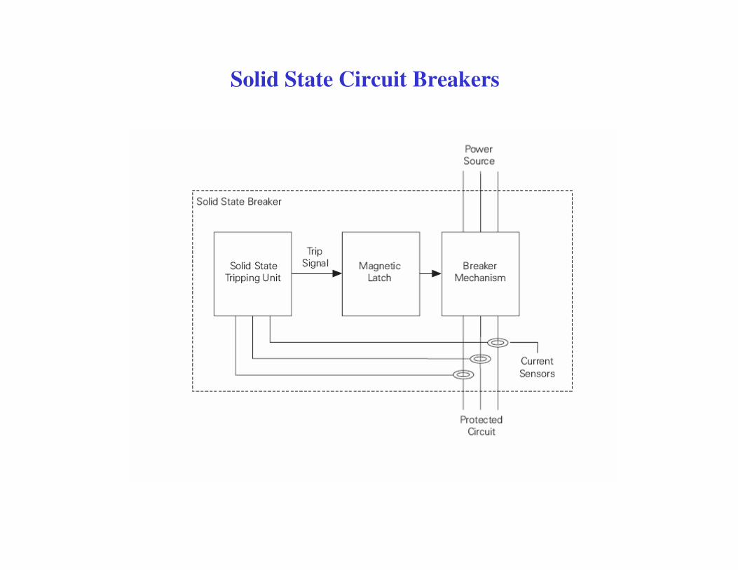
Solid State Circuit Breakers

Ajustes disponibles en Interruptores (relé basado en microprocesador)

I1 I2 I3
Ejemplo de interruptor automático (Relé con microprocesador)
t1
t2


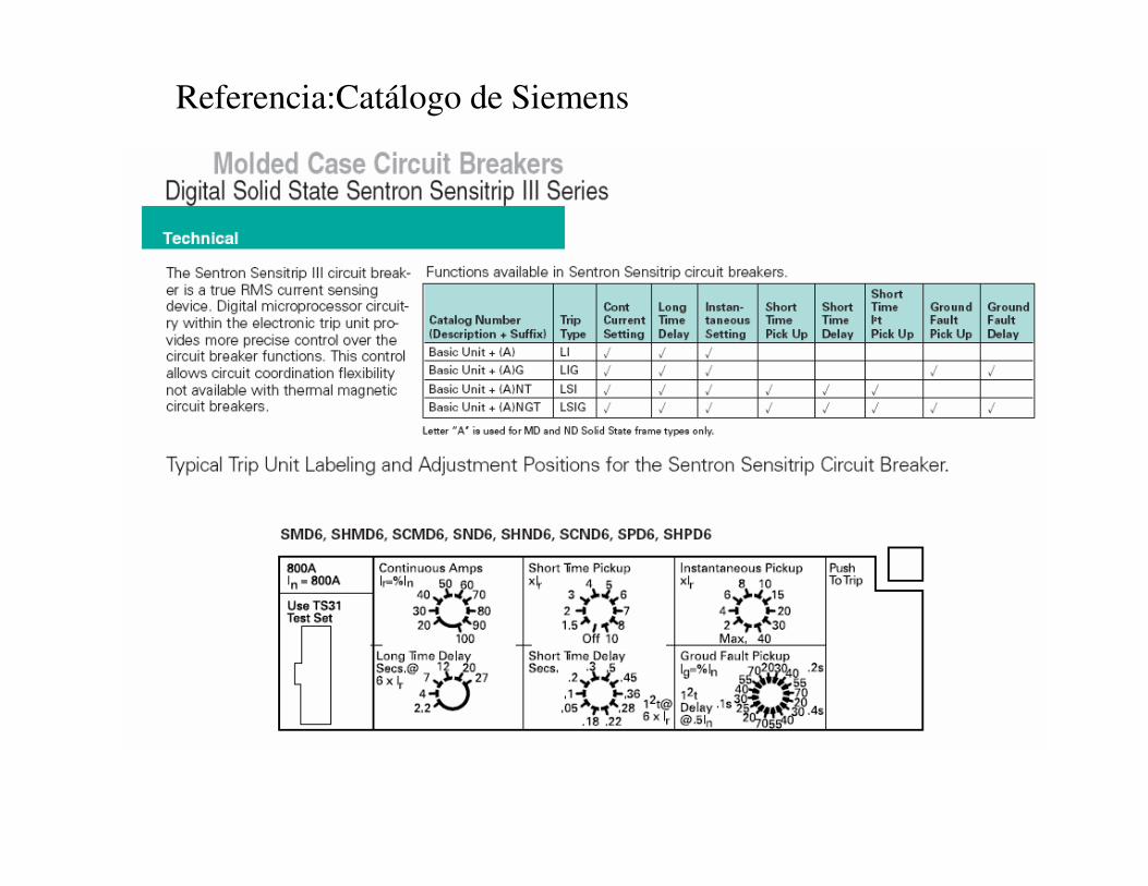
Referencia:Catálogo de Siemens

Coordinación de las protecciones
Inom = 2500A
Main Breaker
Relevador
Feeder Breaker
Inom=400 A
AE
InomT 2405)480(3
32000== AInom
M65≈

Coordinación de las protecciones (Corrientes referidas al lado de 480 V)
IM(nom) = 65 A
IM (inrush)=65*6=390 A
IOL=65*1.25=81.3 A
I pickup(MP) = 430 A > Inrush motor!!
I MB(LTPU) = 2500*1.1=2,750 A
I MB(STPU) = 2500*1.3=3,750 A
I MB(Inst) = 2500*10=25,000 A
I FB(Inst) = 400*6=2,400 A
I FB(PU) = 400*1.1=440 A
IT (inrush)=8*2.4= 19.2 kA
IRelay(pu) = 2*2,500=5kA
∆∆ ∆∆T
=0
.17
s∆∆ ∆∆
T=
4.7
s
CO-11 Extremely inverse relay
Los elementos deberán contar con la capacidad interruptiva
adecuada de acuerdo a los resultados del estudio de CC

Ejemplo coordinación planta industrial
SE 1
FU SE-1Tipo SM-4, 100E Sensor 100 ACap. Int. 6.3 kA
BUS-SE 1 33 KVIsc 3 Ph 4505 AIsc SLG 4445 A
CBL-52-1G
BUS-SE 1Isc 3 Ph 45329 AIsc SLG 5 A
TX Inrush
SE 1
CBL-52-1G
SE 1
FU SE-1
52-1
52-1G
CBL-52-1G
0.5 1 10 100 1K 10K0.01
0.10
1
10
100
1000
CURRENT IN AMPERES
SE 1.tcc Ref. Voltage: 33000 Current Scale X 10^0
TIM
E IN
SE
CO
ND
S
52-14000 ASensor 4000 ACap. Int. 85 kATipo USR H-3 Settings
LTPU 0.7; 1.1LTD 4.0STPU 3.0STD-I2T 0.2(I^2 T In)
52-1G
1600 ASensor 1600 ACap. Int. 65 kATipo USR H-3 Settings
LTPU 0.7; 1.1LTD 4.0STPU 4.0STD-I2T 0.1(I^2 T In)INST 8.0

CBL-52-1F
BUS-TDF 1AIsc 3 Ph 39476 AIsc SLG 5 A
COMPRESOR 3
1BTipo LA Sensor 400 ASettings
Thermal Curve (Fixed) INST (5-10 x Trip) 6.0
Cap. Int. 22.0 kA
CBL-1B
BUS-1BIsc 3 Ph 29257 AIsc SLG 5 A
Thermal Curve (Fixed) INST (5-10 x Trip) 5.0
SE 1
BUS-SE 1Isc 3 Ph 45329 AIsc SLG 5 A
CBL-52-1F
MS
CBL-1B
52-1
52-1F
CBL-52-1F
COMPRESOR 3
1B
CBL-1B
0.5 1 10 100 1K 10K0.01
0.10
1
10
100
1000
CURRENT IN AMPERES
SE 1 COMPRESORES.tcc Ref. Voltage: 600 Current Scale X 10^1
TIM
E IN
SE
CO
ND
S
52-1F1600 ASensor 1600 ACap. Int. 65 kATipo USR H-3 Settings
LTPU 0.8; 1.1LTD 4.0STPU 4.0STD-I2T 0.1(I^2 T In)INST 8.0
52-14000 ASensor 4000 ACap. Int. 85 kATipo USR H-3 Settings
LTPU 0.7; 1.1LTD 4.0STPU 3.0STD-I2T 0.2(I^2 T In)
Ejemplo coordinación planta industrial


![dominiambiental.com · Modelo de impulsor: Semiabierto Diémtro máx. partículas: 10 mm Cable con clavija Schuko MPG18 Modelo Descarga Inom [A] Cable [m] Precio KP 150 M 1,3 10 011H1300](https://static.fdocuments.ec/doc/165x107/5e89fbcf188110600d37c98f/modelo-de-impulsor-semiabierto-dimtro-mx-partculas-10-mm-cable-con-clavija.jpg)