Presentacion P139
84
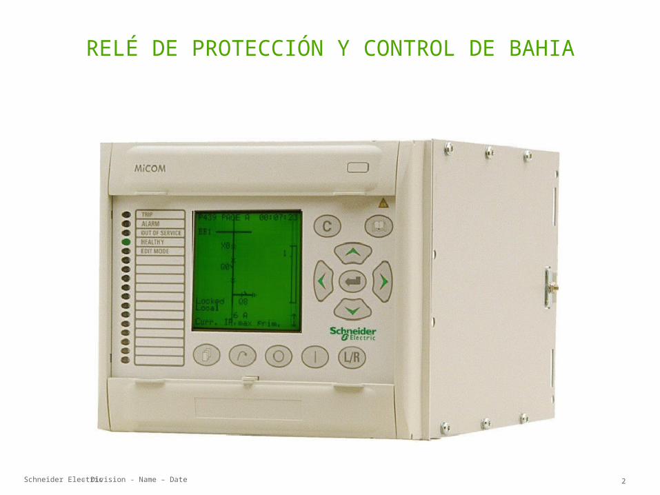
MiCOM P139 Relé de protección de alimentador y controlador de bahía
description
MiCOM P139
Transcript of Presentacion P139
MiCOM P139 Relé de protección de alimentador y controlador de bahía
Schneider Electric 2- Division - Name – Date
RELÉ DE PROTECCIÓN Y CONTROL DE BAHIA
Schneider Electric 3- Division - Name – Date
Funciones & Características
Funciones & Características
Schneider Electric 4- Division - Name – Date
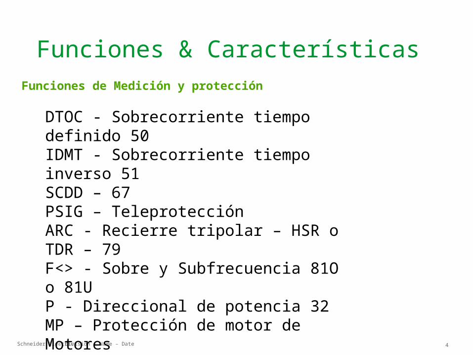
Funciones de Medición y protección
DTOC - Sobrecorriente tiempo definido 50IDMT - Sobrecorriente tiempo inverso 51SCDD – 67 PSIG – Teleprotección ARC - Recierre tripolar – HSR o TDR – 79F<> - Sobre y Subfrecuencia 81O o 81UP - Direccional de potencia 32 MP – Protección de motor de Motores THERM – Protección termica
Funciones & Características
Schneider Electric 5- Division - Name – Date
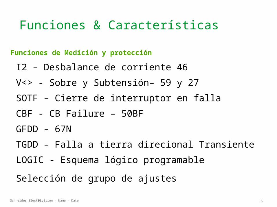
Funciones de Medición y protección
I2 – Desbalance de corriente 46 V<> - Sobre y Subtensión– 59 y 27 SOTF – Cierre de interruptor en falla CBF - CB Failure – 50BF GFDD – 67N TGDD – Falla a tierra direcional Transiente LOGIC - Esquema lógico programable Selección de grupo de ajustes
Funciones & Características
Schneider Electric 6- Division - Name – Date
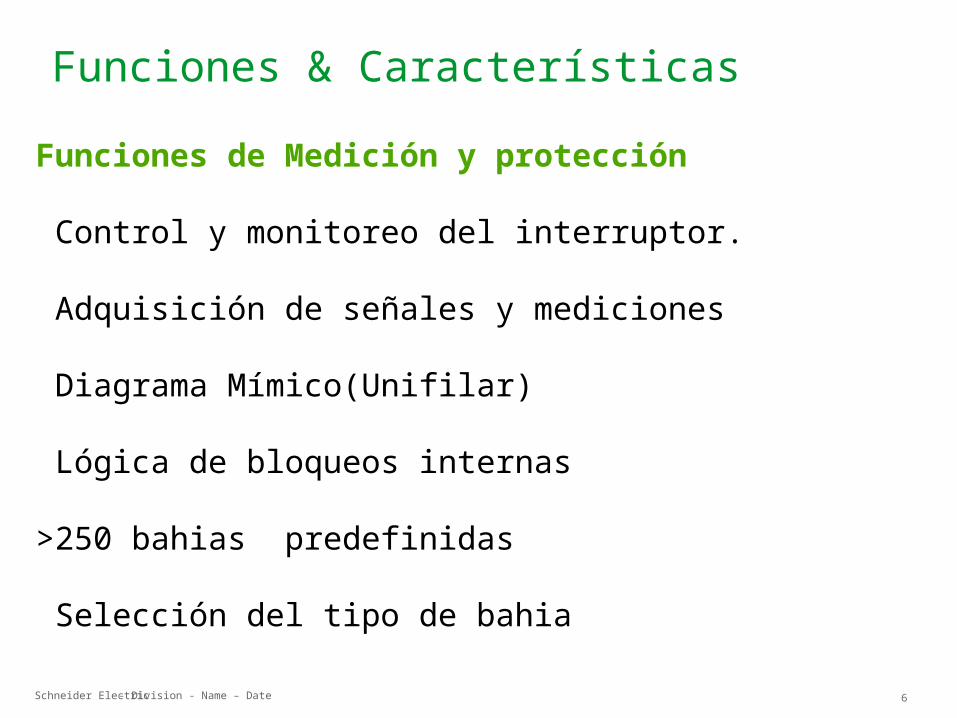
Funciones de Medición y protección
Control y monitoreo del interruptor.
Adquisición de señales y mediciones
Diagrama Mímico(Unifilar)
Lógica de bloqueos internas
>250 bahias predefinidas
Selección del tipo de bahia
Funciones & Características
Schneider Electric 7- Division - Name – Date
Hardware
HardwareHardware
Schneider Electric 8- Division - Name – Date
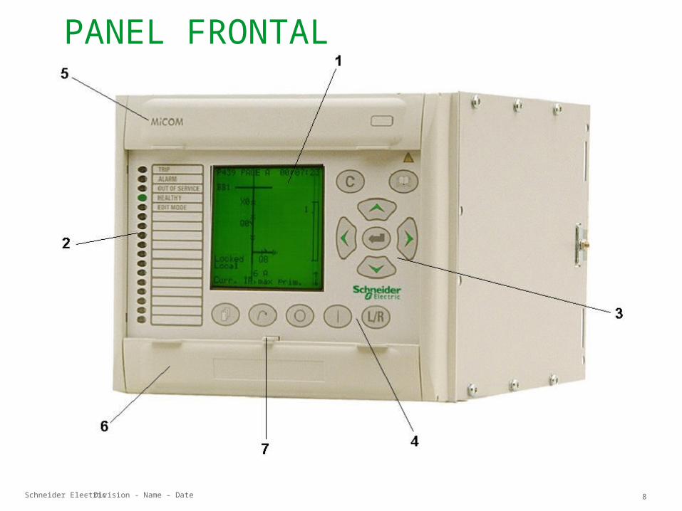
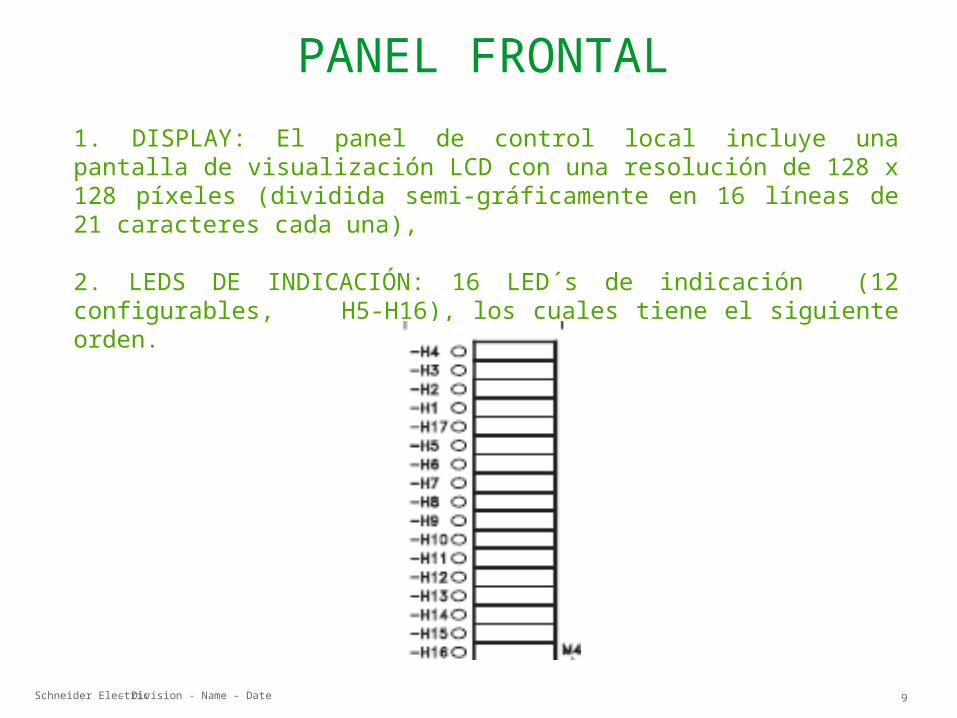
PANEL FRONTAL
Schneider Electric 9- Division - Name – Date
PANEL FRONTAL1. DISPLAY: El panel de control local incluye una pantalla de visualización LCD con una resolución de 128 x 128 píxeles (dividida semi-gráficamente en 16 líneas de 21 caracteres cada una),
2. LEDS DE INDICACIÓN: 16 LED´s de indicación (12 configurables, H5-H16), los cuales tiene el siguiente orden.
Schneider Electric 10- Division - Name – Date
PANEL FRONTAL
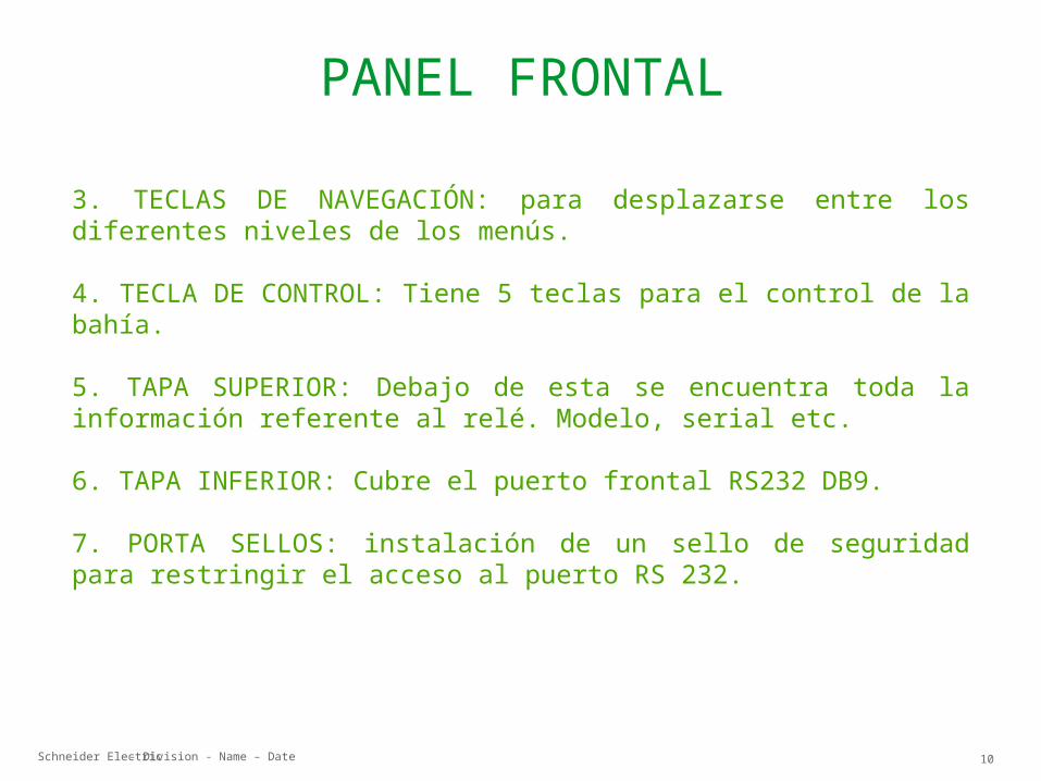
3. TECLAS DE NAVEGACIÓN: para desplazarse entre los diferentes niveles de los menús.
4. TECLA DE CONTROL: Tiene 5 teclas para el control de la bahía.
5. TAPA SUPERIOR: Debajo de esta se encuentra toda la información referente al relé. Modelo, serial etc.
6. TAPA INFERIOR: Cubre el puerto frontal RS232 DB9.
7. PORTA SELLOS: instalación de un sello de seguridad para restringir el acceso al puerto RS 232.
Schneider Electric 11- Division - Name – Date
VISTA POSTERIOR
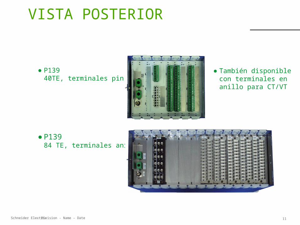
● P13940TE, terminales pin
● P13984 TE, terminales anillo
● También disponible con terminales en anillo para CT/VT
Schneider Electric 12- Division - Name – Date
P139
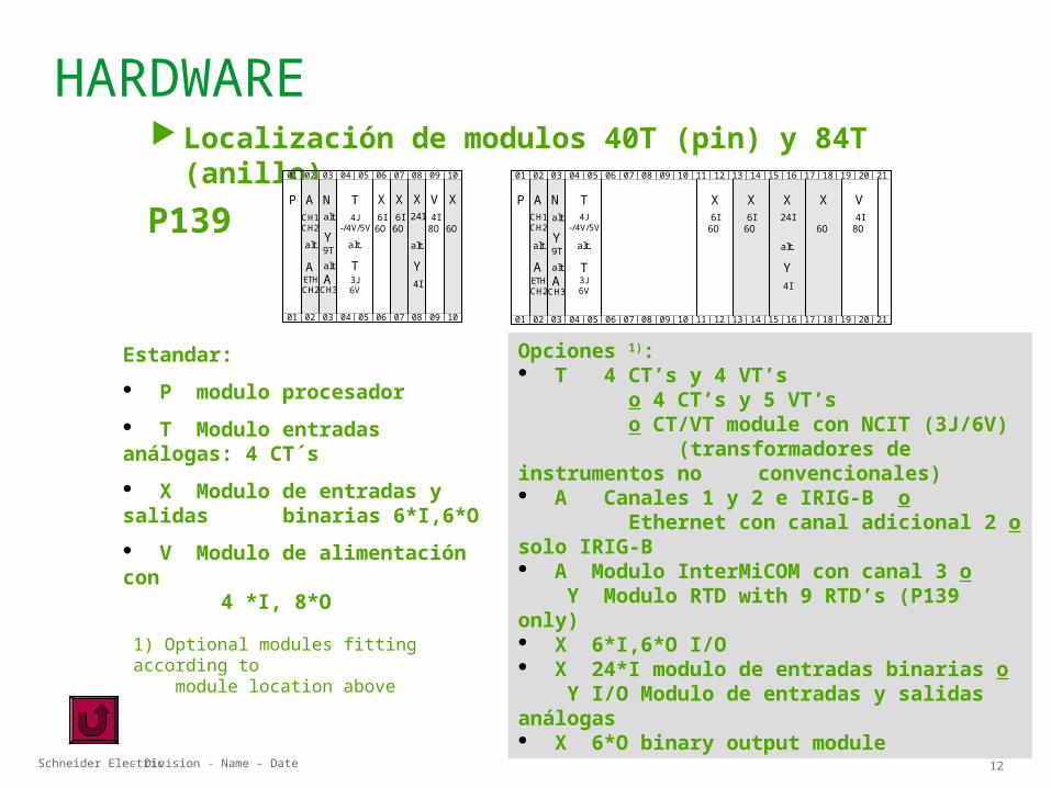
Localización de modulos 40T (pin) y 84T (anillo)
Estandar: P modulo procesador T Modulo entradas análogas: 4 CT´s X Modulo de entradas y salidas
binarias 6*I,6*O V Modulo de alimentación con 4 *I, 8*O
1) Optional modules fitting according to module location above
Opciones 1): T 4 CT’s y 4 VT’s o 4 CT’s y 5 VT’s o CT/VT module con NCIT (3J/6V) (transformadores de instrumentos no convencionales) A Canales 1 y 2 e IRIG-B o Ethernet con canal adicional 2 o solo IRIG-B A Modulo InterMiCOM con canal 3 o Y Modulo RTD with 9 RTD’s (P139 only) X 6*I,6*O I/O X 24*I modulo de entradas binarias o Y I/O Modulo de entradas y salidas análogas X 6*O binary output module
01
01
02
02
03
03
04
04
05
05
06
06
07
07
08
08
09
09
10
10
V4I
8O
X
6O
Y4I
X6I
6O
X6I6O
X24I
alt.
T4J
-/4V/5V
AP N
alt.
T3J6V
alt.
Y9Talt.A
CH3
CH1CH2alt.
AETHCH2
01
01
02
02
03
03
04
04
05
05
06
06
07
07
08
08
09
09
10
10
T4J
-/4V/5V
AP11
11
12
12
13
13
14
14
15
15
16
16
X6I
6O
17
17
18
18
X
6O
19
19
20
20
V4I8O
21
21
X6I
6O
N X24I
Y4I
alt.alt.
T3J6V
alt.
Y9Talt.A
CH3
CH1CH2alt.
AETHCH2
HARDWARE
Schneider Electric 13- Division - Name – Date
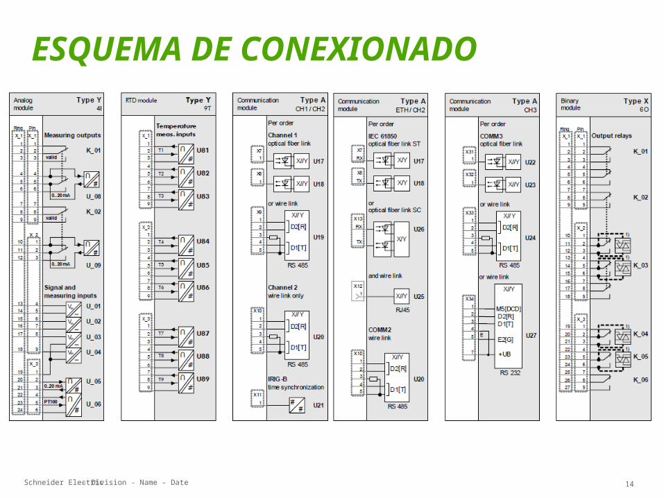
ESQUEMA DE CONEXIONADO
Schneider Electric 14- Division - Name – Date
ESQUEMA DE CONEXIONADO
Schneider Electric 15- Division - Name – Date
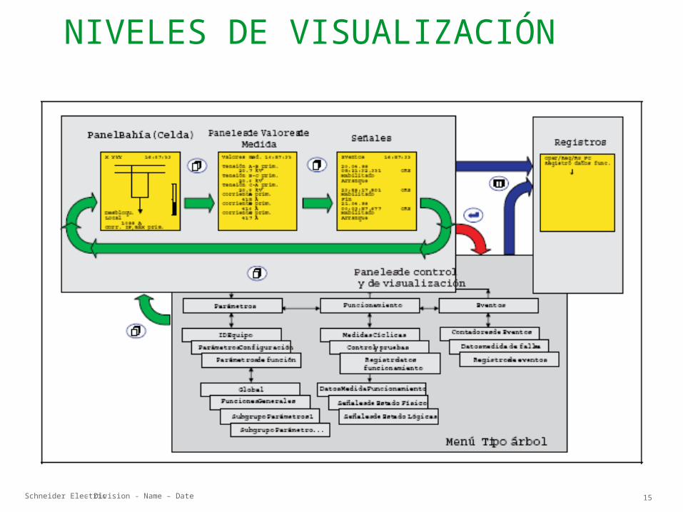
NIVELES DE VISUALIZACIÓN
Schneider Electric 16- Division - Name – Date
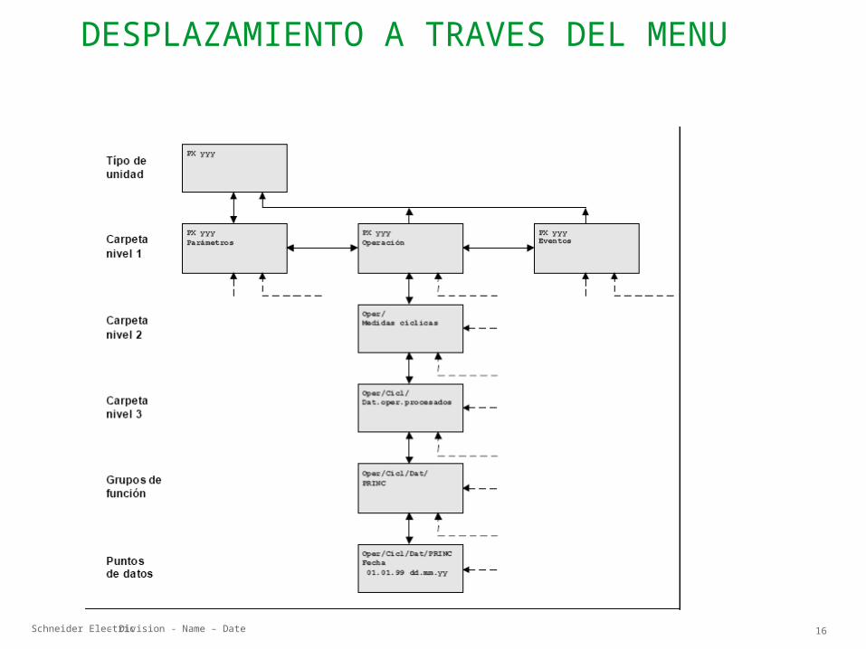
DESPLAZAMIENTO A TRAVES DEL MENU
Schneider Electric 17- Division - Name – Date
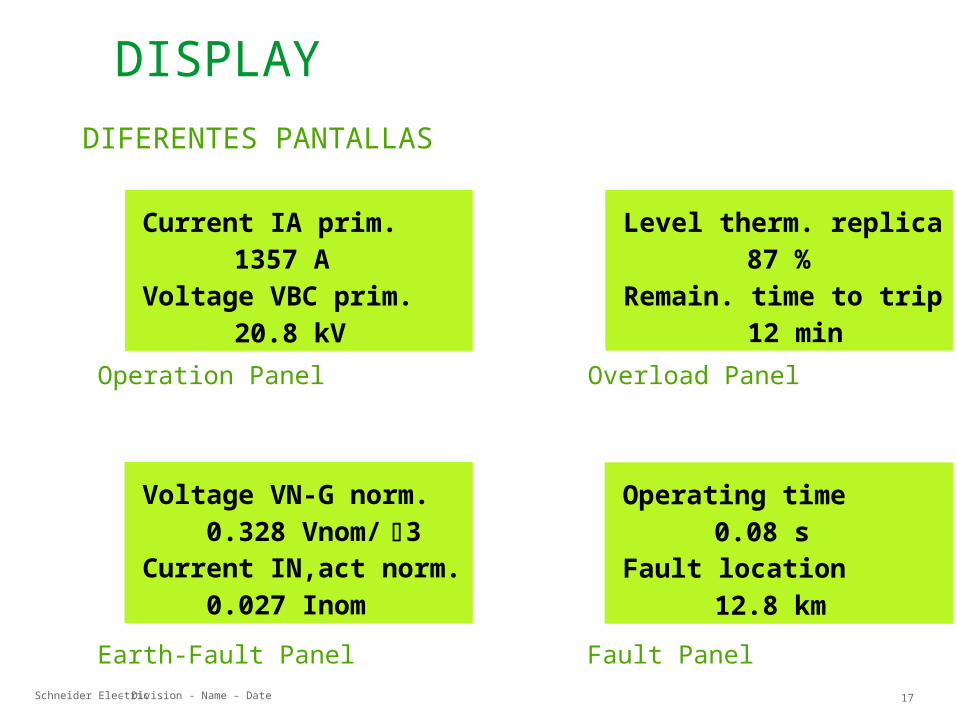
Earth-Fault Panel Fault Panel
Operation Panel Overload Panel
Voltage VN-G norm. 0.328 Vnom/ 3Current IN,act norm. 0.027 Inom
Current IA prim. 1357 AVoltage VBC prim. 20.8 kV
Level therm. replica 87 %Remain. time to trip 12 min
Operating time 0.08 sFault location 12.8 km
DIFERENTES PANTALLAS
DISPLAY
Schneider Electric 18- Division - Name – Date
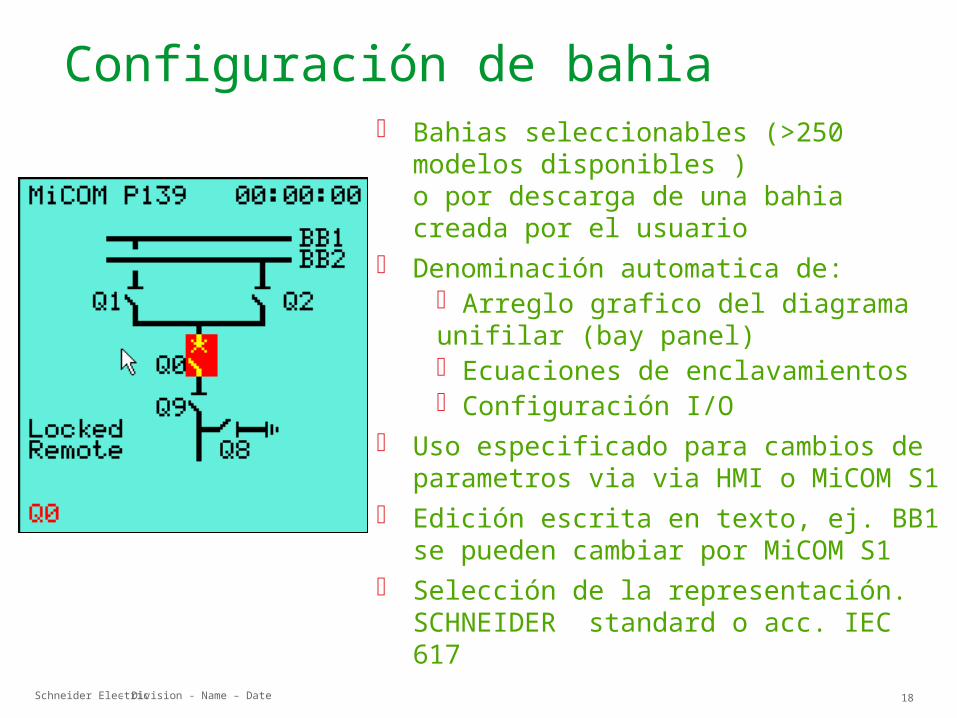
Bahias seleccionables (>250 modelos disponibles )o por descarga de una bahia creada por el usuario
Denominación automatica de: Arreglo grafico del diagrama unifilar (bay panel) Ecuaciones de enclavamientos Configuración I/O
Uso especificado para cambios de parametros via via HMI o MiCOM S1
Edición escrita en texto, ej. BB1 se pueden cambiar por MiCOM S1
Selección de la representación. SCHNEIDER standard o acc. IEC 617
Configuración de bahia
Schneider Electric 19- Division - Name – Date
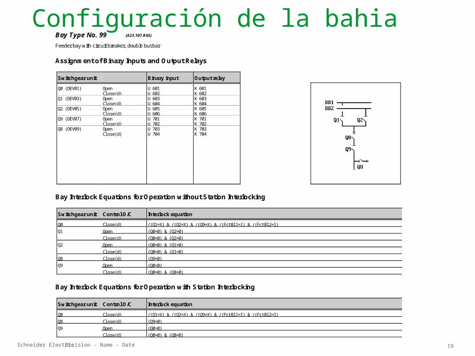
Configuración de la bahiaBay Type No. 99 (A23.107.R05)
Feeder bay with circuit breaker, double busbar
Assignment of Binary Inputs and Output Relays
Switchgear unit Binary input Output relay
Q0 (DEV01) Q1 (DEV03) Q2 (DEV05) Q9 (DEV07) Q8 (DEV09)
OpenCl ose(d) OpenCl ose(d) OpenCl ose(d) OpenCl ose(d) OpenCl ose(d)
U 601U 602 U 603U 604 U 605U 606 U 701U 702 U 703U 704
K 601K 602 K 603K 604 K 605K 606 K 701K 702 K 703K 704
Bay Interlock Equations for Operation without Station Interlocking
Switchgear unit Control O/C Interlock equation
Q0 Cl ose(d) / (Q1=X) & / (Q2=X) & / (Q9=X) & / (FctBl 1=I ) & / (FctBl 2=I )Q1 Open (Q0=0) & (Q2=0)
Cl ose(d) (Q0=0) & (Q2=0)Q2 Open (Q0=0) & (Q1=0)
Cl ose(d) (Q0=0) & (Q1=0)Q8 Cl ose(d) (Q9=0)Q9 Open (Q0=0)
Cl ose(d) (Q0=0) & (Q8=0)
Bay Interlock Equations for Operation with Station Interlocking
Switchgear unit Control O/C Interlock equation
Q0 Cl ose(d) / (Q1=X) & / (Q2=X) & / (Q9=X) & / (FctBl 1=I ) & / (FctBl 2=I )Q8 Cl ose(d) (Q9=0)Q9 Open (Q0=0)
Cl ose(d) (Q0=0) & (Q8=0)
Schneider Electric 20- Division - Name – Date
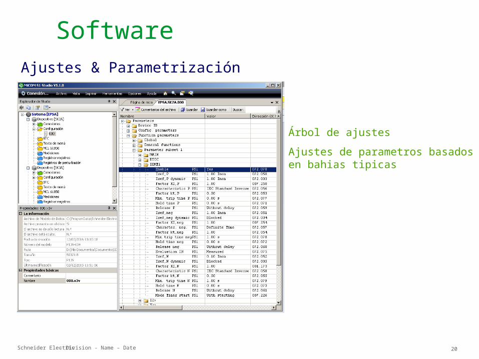
Árbol de ajustes Ajustes de parametros basados en
bahias tipicas
SoftwareAjustes & Parametrización
Schneider Electric 21- Division - Name – Date
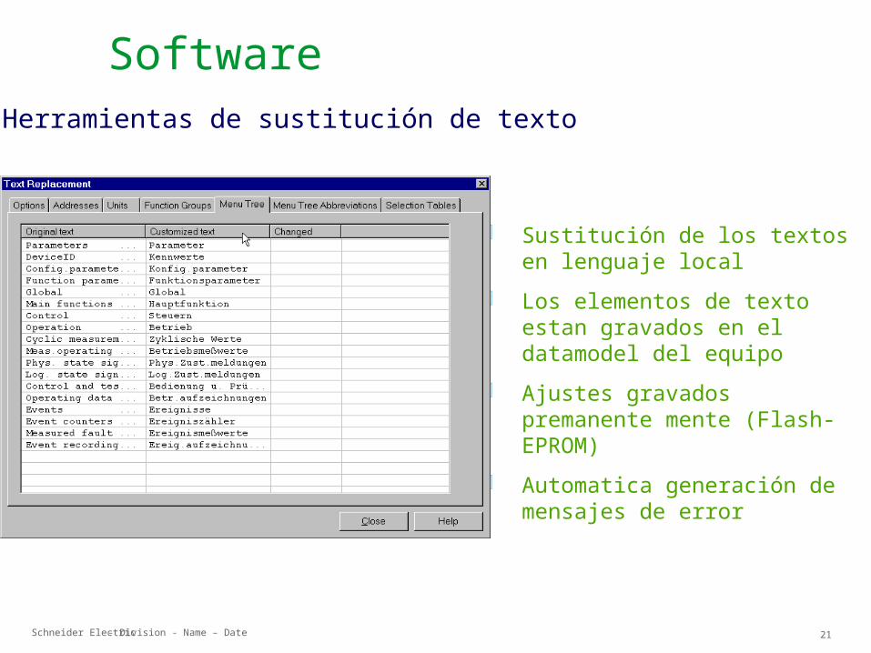
Sustitución de los textos en lenguaje local
Los elementos de texto estan gravados en el datamodel del equipo
Ajustes gravados premanente mente (Flash-EPROM)
Automatica generación de mensajes de error
SoftwareHerramientas de sustitución de texto
Schneider Electric 22- Division - Name – Date
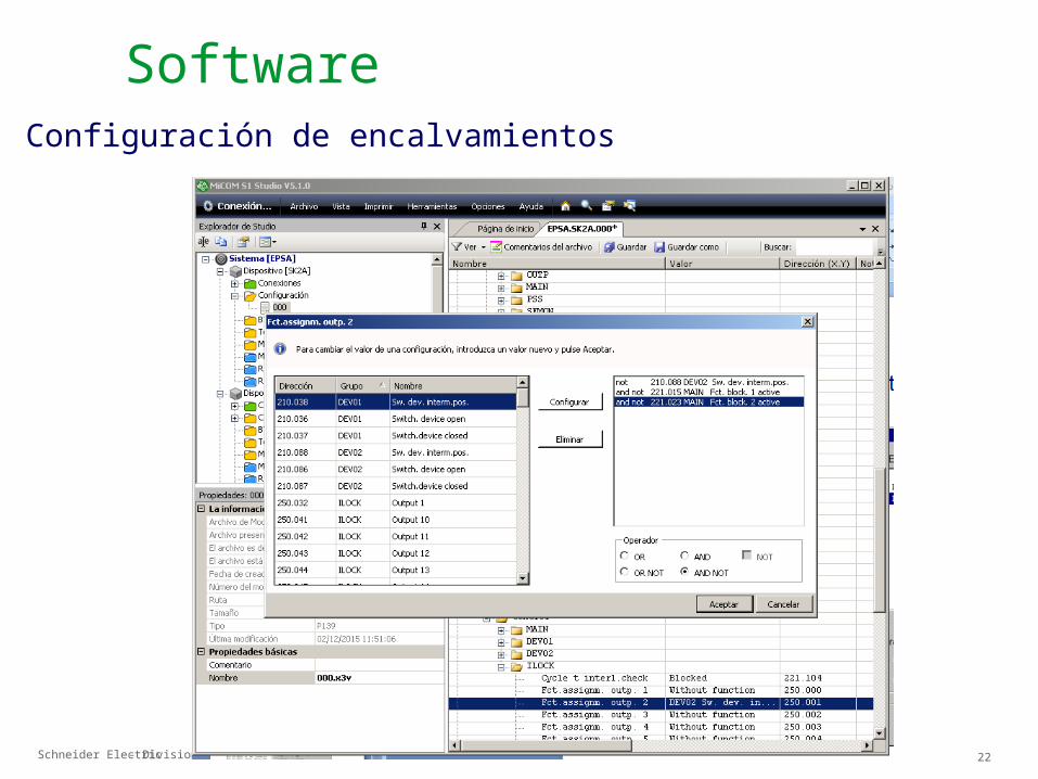
Configuración de encalvamientos Software
Schneider Electric 23- Division - Name – Date
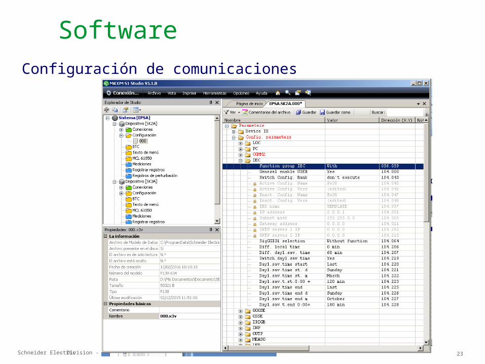
Configuración de comunicaciones
Software
Schneider Electric 24- Division - Name – Date
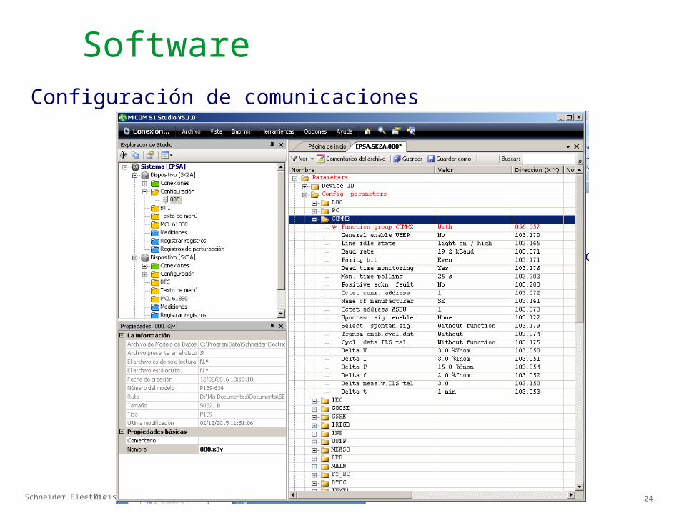
SoftwareConfiguración de comunicaciones
Schneider Electric 25- Division - Name – Date
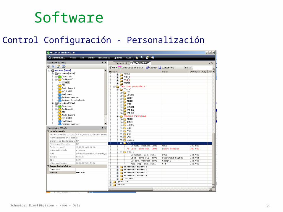
Control Configuración - Personalización
Software
Schneider Electric 26- Division - Name – Date
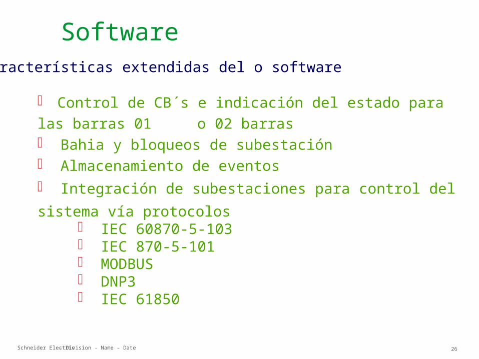
Control de CB´s e indicación del estado para las barras 01 o 02 barras Bahia y bloqueos de subestación Almacenamiento de eventos Integración de subestaciones para control del sistema vía protocolos
IEC 60870-5-103 IEC 870-5-101 MODBUS DNP3 IEC 61850
Características extendidas del o software
Software
Schneider Electric 27- Division - Name – Date
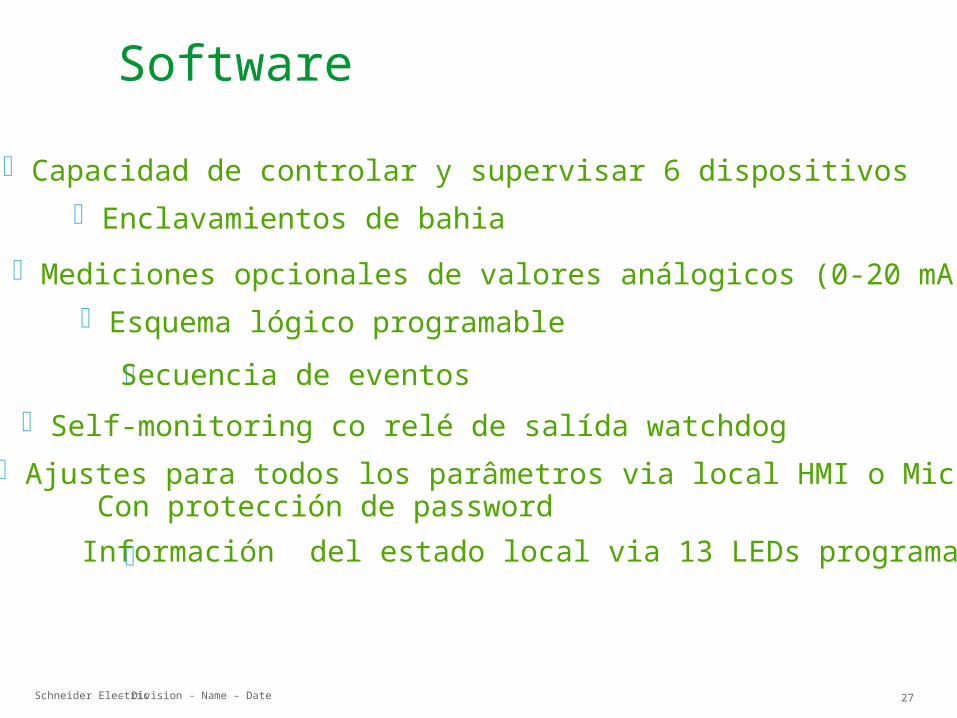
Capacidad de controlar y supervisar 6 dispositivos Enclavamientos de bahia
Mediciones opcionales de valores análogicos (0-20 mA) Esquema lógico programable
Secuencia de eventos Self-monitoring co relé de salída watchdog Ajustes para todos los parâmetros via local HMI o Micom S1
Con protección de password Información del estado local via 13 LEDs programables
Software
Schneider Electric 28- Division - Name – Date
SCDD
MP I2>
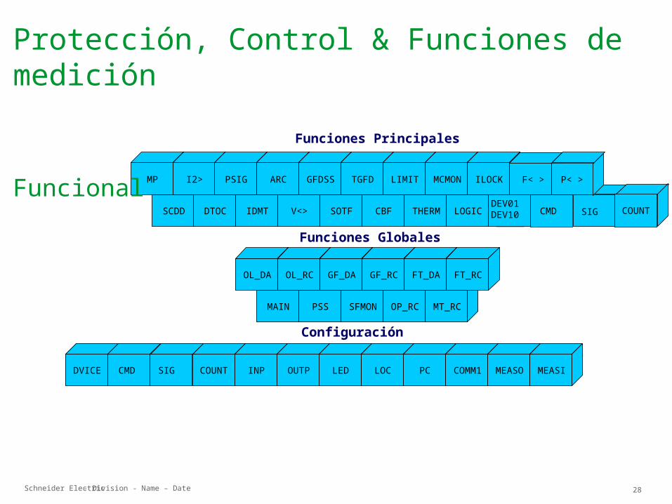
Protección, Control & Funciones de medición
Funcional
DTOC IDMT V<> SOTF CBF THERM LOGIC
MAIN PSS
PSIG ARC GFDSS TGFD LIMIT MCMON
SFMON OP_RC MT_RC
OL_DA OL_RC GF_DA GF_RC
COUNT INP OUTP LED LOC PC COMM1
FT_DA FT_RC
MEASO MEASI
...
DEV10
DEV01
ILOCK
Funciones Principales
Funciones Globales
Configuración
CMD SIG COUNT
DVICE CMD SIG
F< > P< >
CMDDEV01DEV10
Schneider Electric 29- Division - Name – Date
FuncionesFunciones
Protección, Control & Funciones de medición
Schneider Electric 30- Division - Name – Date
DVICE
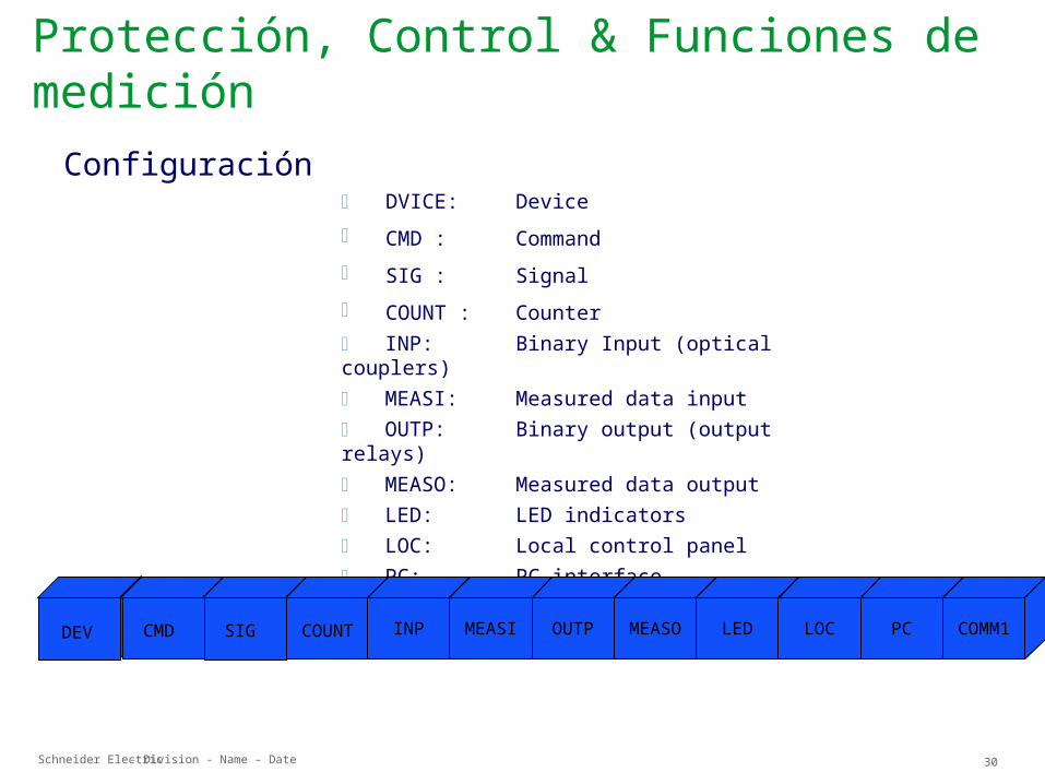
DVICE: Device CMD : Command SIG : Signal COUNT : Counter INP: Binary Input (optical couplers) MEASI: Measured data input OUTP: Binary output (output relays) MEASO: Measured data output LED: LED indicators LOC: Local control panel PC: PC interface COMM1: Communication interface 1
DVICE INP MEASI OUTP MEASO LED LOC PC COMM1
Configuración
DVICE DVICEDEV CMD SIG COUNT
Protección, Control & Funciones de medición
Schneider Electric 31- Division - Name – Date
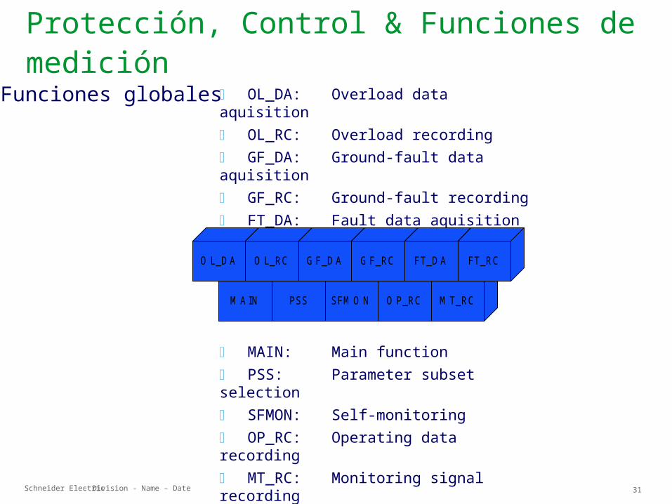
OL_DA: Overload data aquisition OL_RC: Overload recording GF_DA: Ground-fault data aquisition GF_RC: Ground-fault recording FT_DA: Fault data aquisition FT_RC: Fault recording
MAIN: Main function PSS: Parameter subset selection SFMON: Self-monitoring OP_RC: Operating data recording MT_RC: Monitoring signal recording
M A IN PSS SFM O N O P_RC M T_RC
O L_D A O L_RC G F_D A G F_RC FT_D A FT_RC
Funciones globales
Protección, Control & Funciones de medición

Schneider Electric 32- Division - Name – Date
M A IN
Main Function
Protección, Control & Funciones de medición
Schneider Electric 33- Division - Name – Date
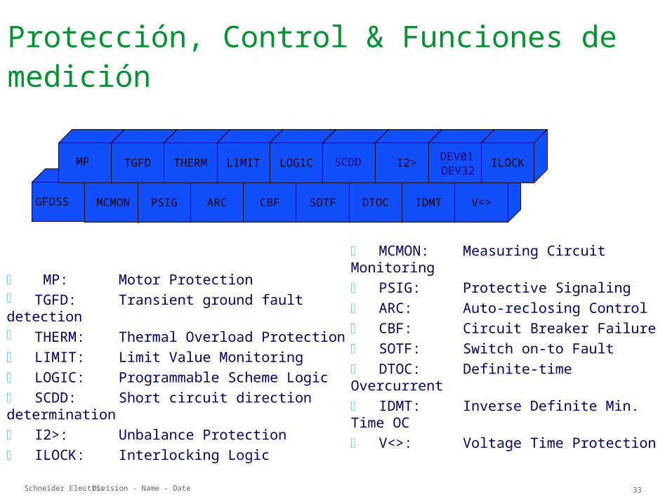
MCMON: Measuring Circuit Monitoring PSIG: Protective Signaling ARC: Auto-reclosing Control CBF: Circuit Breaker Failure SOTF: Switch on-to Fault DTOC: Definite-time Overcurrent IDMT: Inverse Definite Min. Time OC V<>: Voltage Time Protection
MP: Motor Protection TGFD: Transient ground fault detection THERM: Thermal Overload Protection LIMIT: Limit Value Monitoring LOGIC: Programmable Scheme Logic SCDD: Short circuit direction determination I2>: Unbalance Protection ILOCK: Interlocking Logic
PSIG ARC CBF SOTF DTOC IDMT V<>GFDSS
MP TGFD THERM LIMIT LOGICDEV01 -DEV32
I2> ILOCKDEV01-DEV32SCDD
MCMONMCMON
Protección, Control & Funciones de medición
Schneider Electric 34- Division - Name – Date
ProteccionesProtecciones
Protección, Control & Funciones de medición
Schneider Electric 35- Division - Name – Date
D TO C
Definite-Time Overcurrent Protection
Protección, Control & Funciones de medición
Schneider Electric 36- Division - Name – Date
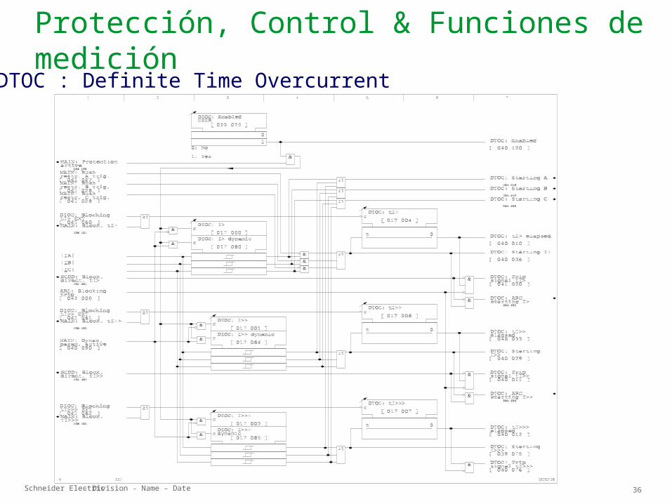
DTOC : Definite Time OvercurrentProtección, Control & Funciones de medición
Schneider Electric 37- Division - Name – Date
Protección, Control & Funciones de medición
ID M T
Inverse-Time Overcurrent Protection
Schneider Electric 38- Division - Name – Date
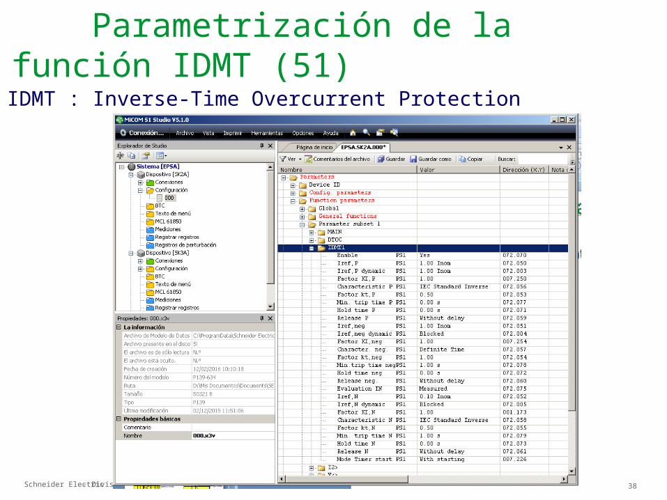
Parametrización de la función IDMT (51)
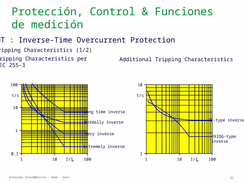
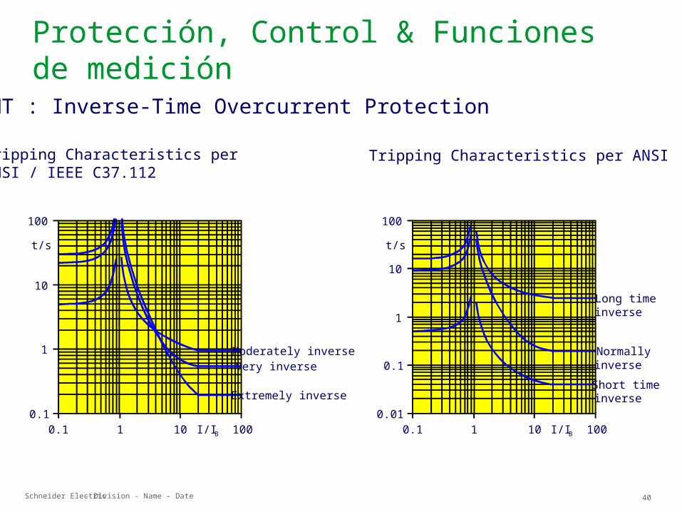
IDMT : Inverse-Time Overcurrent Protection
Schneider Electric 39- Division - Name – Date
Protección, Control & Funciones de medición
RI-type inverse
RXIDG-typeinverse
100101 I/I B1
10
t/s
Long time inverse
Normally inverse
1001010.1
100
t/s
Very inverse
Extremely inverse
10
1
I/I B
Tripping Characteristics perIEC 255-3
Additional Tripping CharacteristicsTripping Characteristics (1/2)
IDMT : Inverse-Time Overcurrent Protection
Schneider Electric 40- Division - Name – Date
Protección, Control & Funciones de medición
Tripping Characteristics perANSI / IEEE C37.112
Tripping Characteristics per ANSI
Long timeinverse
Short timeinverse
10010.1 I/I B0.01
100t/s10
1
0.1
10
Normallyinverse
Moderately inverse
Extremely inverse
10010.1 I/I B0.1
100t/s
10
1
10
Very inverse
IDMT : Inverse-Time Overcurrent Protection
Schneider Electric 41- Division - Name – Date
Protección, Control & Funciones de medición
SC D D
Short Circuit Direction Determination
Schneider Electric 42- Division - Name – Date
Protección, Control & Funciones de medición
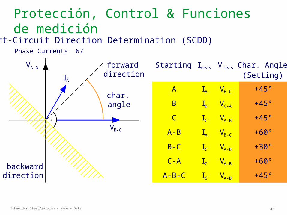
Phase Currents 67
Starting Imeas Vmeas Char. Angle(Setting)
ABC
A-BB-CC-A
A-B-C
IAIBICIAICICIC
VB-C
VC-A
VA-B
VB-C
VA-B
VA-B
VA-B
+45°+45°+45°+60°+30°+60°+45°
backwarddirection
char.angle
VB-C
IAforwarddirection
VA-G
Short-Circuit Direction Determination (SCDD)
Schneider Electric 43- Division - Name – Date
Protección, Control & Funciones de medición
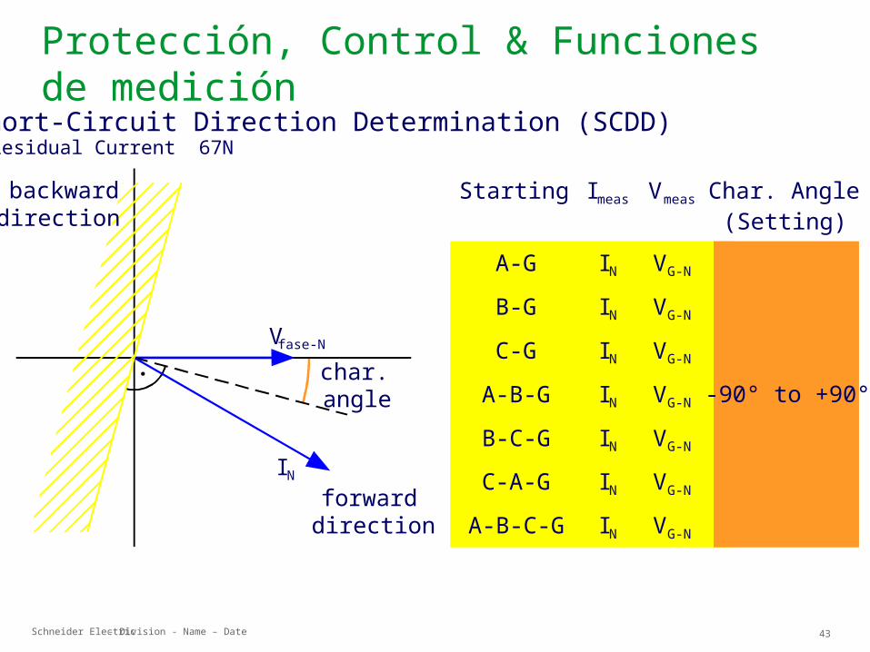
Residual Current 67N
Starting Imeas Vmeas Char. Angle(Setting)
A-GB-GC-G
A-B-GB-C-GC-A-G
A-B-C-G
INININININININ
VG-N
VG-N
VG-N
VG-N
VG-N
VG-N
VG-N
-90° to +90°
backwarddirection
char.angle
Vfase-N
INforwarddirection
Short-Circuit Direction Determination (SCDD)

Schneider Electric 44- Division - Name – Date
Protección, Control & Funciones de medición
A RC
Auto-Reclosing Control
Schneider Electric 45- Division - Name – Date
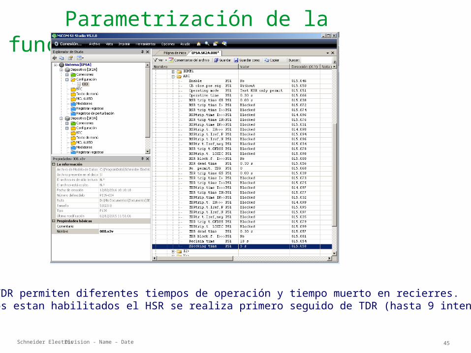
Parametrización de la función ARC (79)
HSR y TDR permiten diferentes tiempos de operación y tiempo muerto en recierres.Si ambos estan habilitados el HSR se realiza primero seguido de TDR (hasta 9 intentos).
Schneider Electric 46- Division - Name – Date
Protección, Control & Funciones de medición
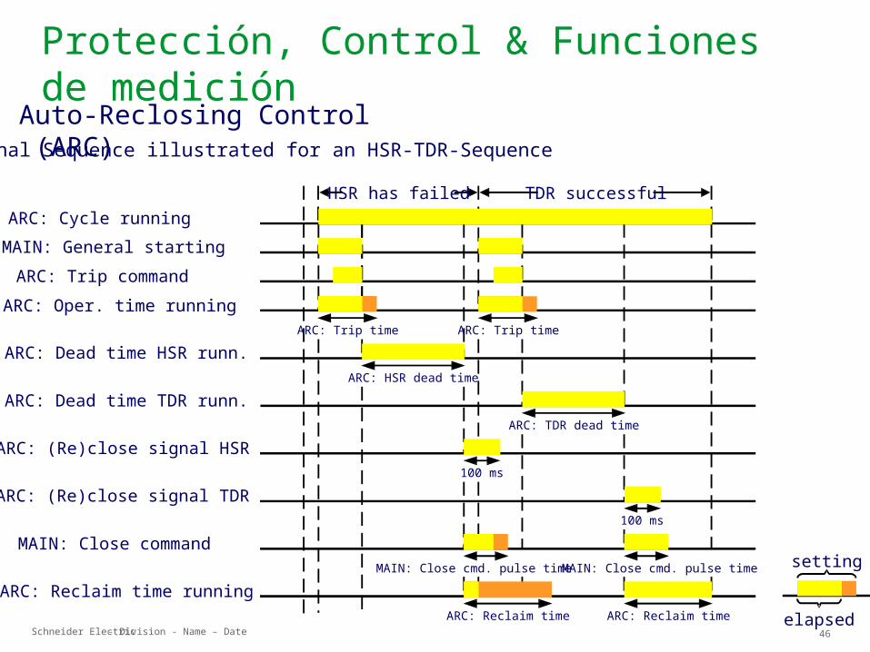
Signal Sequence illustrated for an HSR-TDR-Sequence
MAIN: General startingARC: Trip commandARC: Oper. time running
ARC: Dead time HSR runn.
ARC: Dead time TDR runn.
ARC: (Re)close signal HSR
ARC: Reclaim time running
ARC: Cycle runningHSR has failed TDR successful
setting
elapsed
ARC: (Re)close signal TDR
MAIN: Close command
ARC: Trip time ARC: Trip time
ARC: HSR dead time
ARC: TDR dead time
100 ms
100 ms
MAIN: Close cmd. pulse timeMAIN: Close cmd. pulse time
ARC: Reclaim time ARC: Reclaim time
Auto-Reclosing Control (ARC)
Schneider Electric 47- Division - Name – Date
Protección, Control & Funciones de medición
PSIG
Protective Signaling
Schneider Electric 48- Division - Name – Date
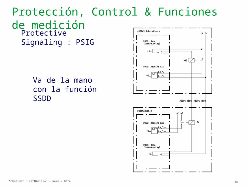
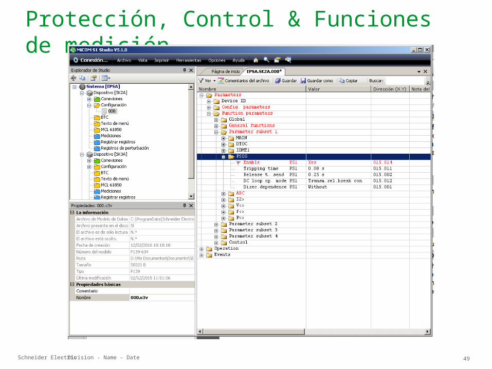
Protección, Control & Funciones de mediciónProtective Signaling : PSIG
Va de la mano con la función SSDD
Schneider Electric 49- Division - Name – Date
Protección, Control & Funciones de medición

Schneider Electric 50- Division - Name – Date
Protección, Control & Funciones de medición
f< >
Over-/Underfrequency Protection
Schneider Electric 51- Division - Name – Date
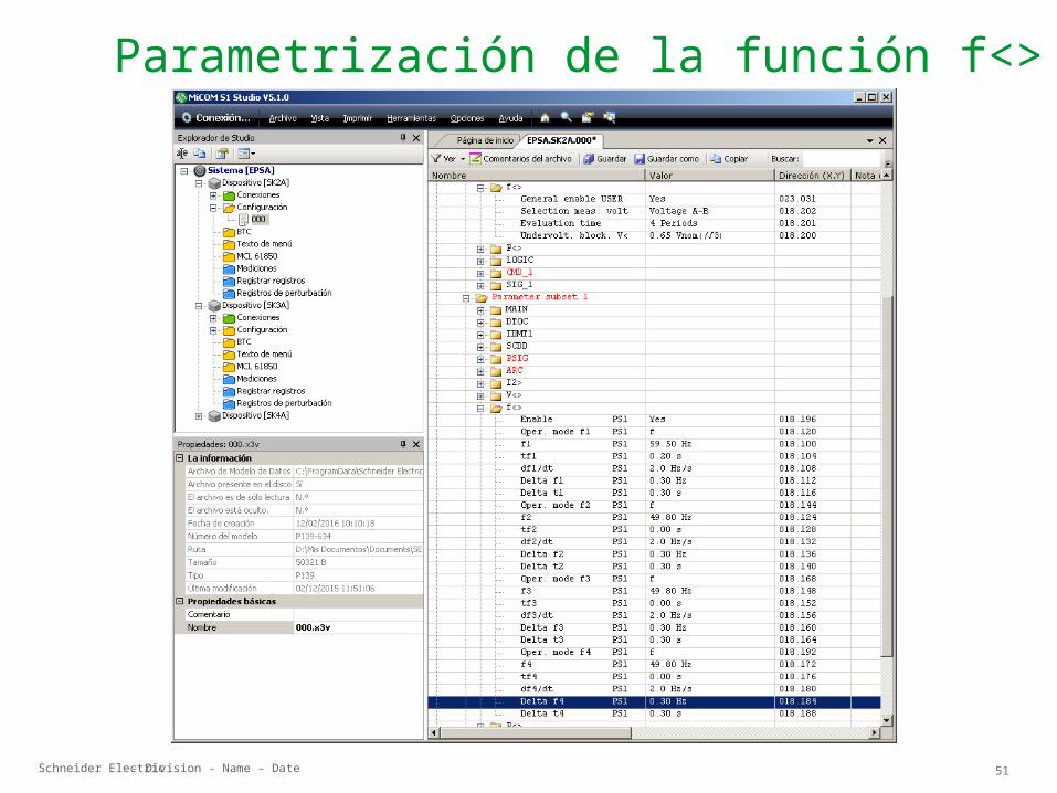
Parametrización de la función f<>
Schneider Electric 52- Division - Name – Date
Protección, Control & Funciones de medición
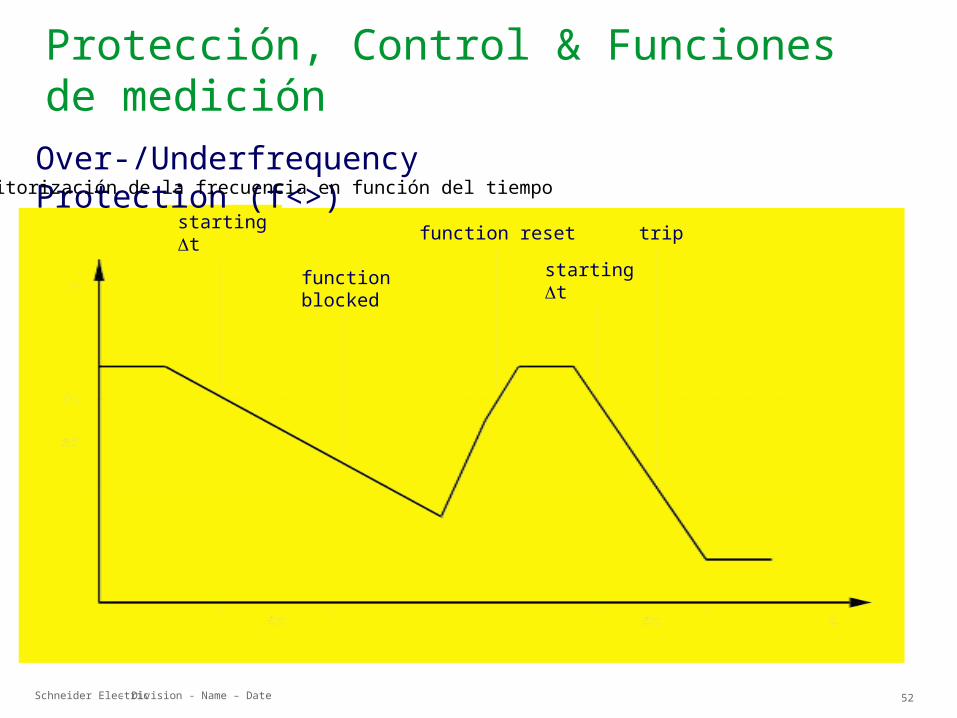
starting t
function blocked
function reset trip
starting t
Over-/Underfrequency Protection (f<>)Monitorización de la frecuencia en función del tiempo

Schneider Electric 53- Division - Name – Date
Protección, Control & Funciones de medición
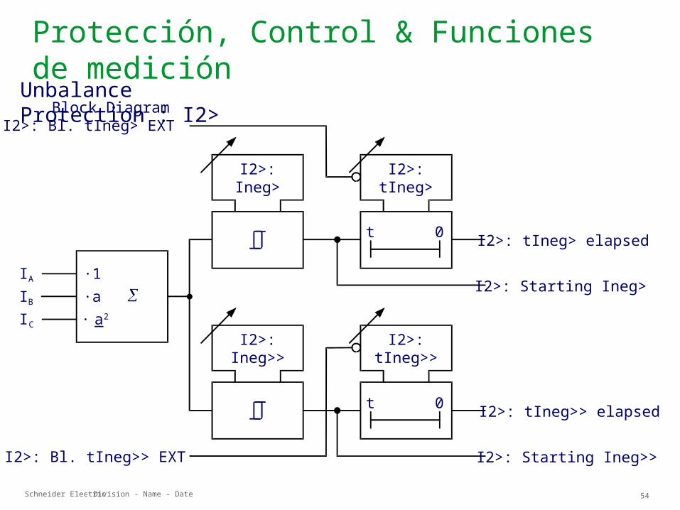
I2>
Unbalance Protection
Schneider Electric 54- Division - Name – Date
Protección, Control & Funciones de medición
Block Diagram
I2>:Ineg>
I AI BI C
·1·a· a 2
I2>:Ineg>>
I2>: Bl. tIneg> EXT
I2>: tIneg> elapsed
I2>: Starting Ineg>
I2>: tIneg>> elapsed
I2>: Starting Ineg>>
I2>:tIneg>
t 0
I2>:tIneg>>
t 0
I2>: Bl. tIneg>> EXT
Unbalance Protection : I2>

Schneider Electric 55- Division - Name – Date
Protección, Control & Funciones de medición
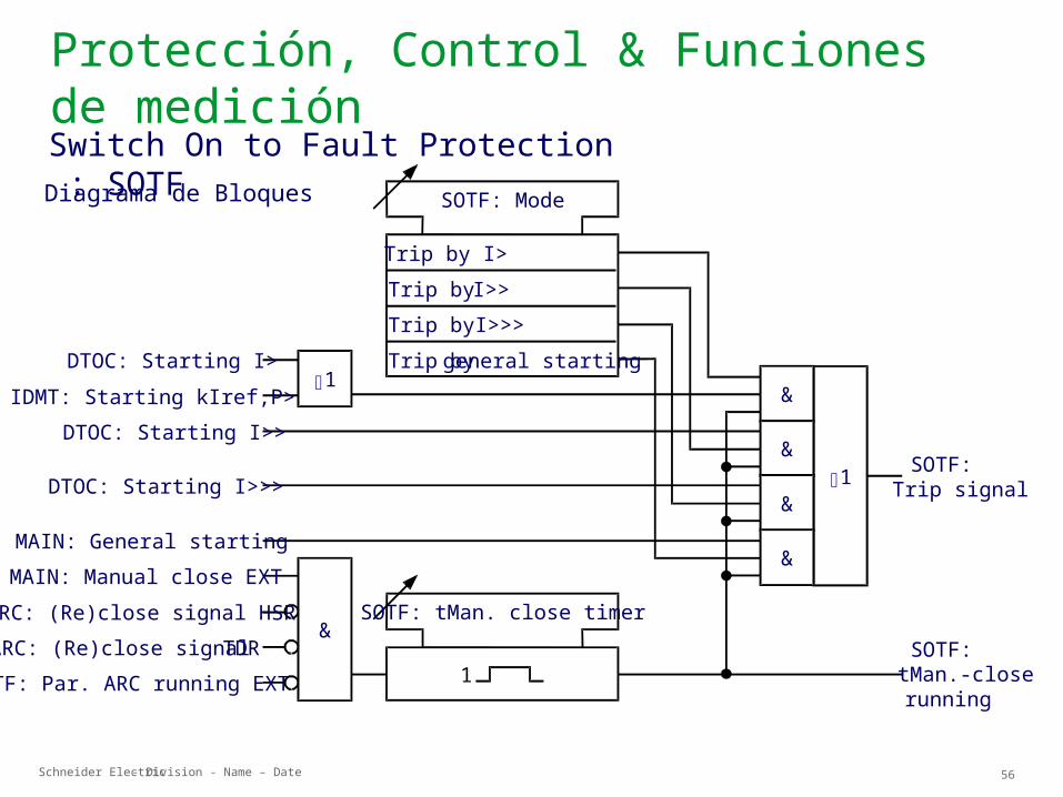
SO TF
Switch On to Fault Protection
Schneider Electric 56- Division - Name – Date
Protección, Control & Funciones de medición
Diagrama de Bloques
DTOC: Starting I>
SOTF: Mode
1
SOTF: tMan. close timer
1
IDMT: Starting kIref,P>DTOC: Starting I>>
DTOC: Starting I>>>
MAIN: General startingMAIN: Manual close EXT
ARC: (Re)close signal HSRARC: (Re)close signal TDR
SOTF: Par. ARC running EXT
1
&
Trip by I>Trip by I>>Trip by I>>>Trip by general starting
&
&
&
&
SOTF:Trip signal
SOTF:tMan.-closerunning
Switch On to Fault Protection : SOTF

Schneider Electric 57- Division - Name – Date
Protección, Control & Funciones de medición
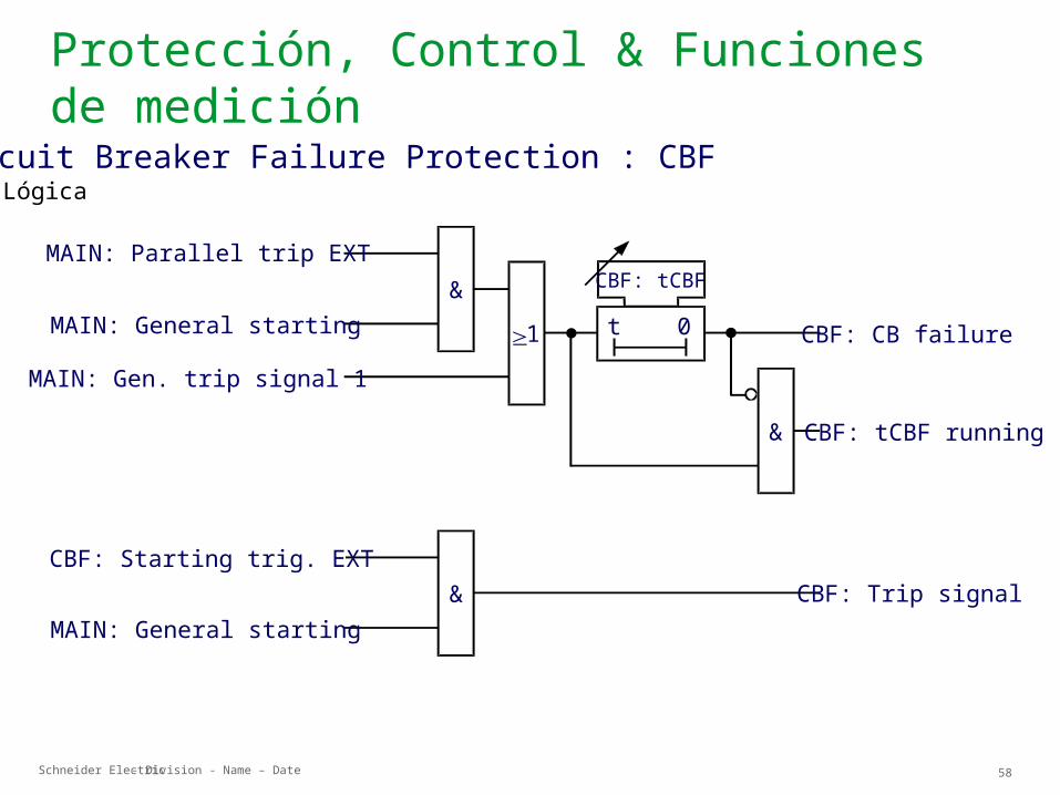
C BF
Circuit Breaker Failure Protection
Schneider Electric 58- Division - Name – Date
Protección, Control & Funciones de medición
1
CBF: tCBFMAIN: Parallel trip EXT
MAIN: General starting
MAIN: Gen. trip signal 1
&
&
&
CBF: CB failure
CBF: tCBF running
CBF: Trip signalCBF: Starting trig. EXT
MAIN: General starting
0t
LógicaCircuit Breaker Failure Protection : CBF
Schneider Electric 59- Division - Name – Date
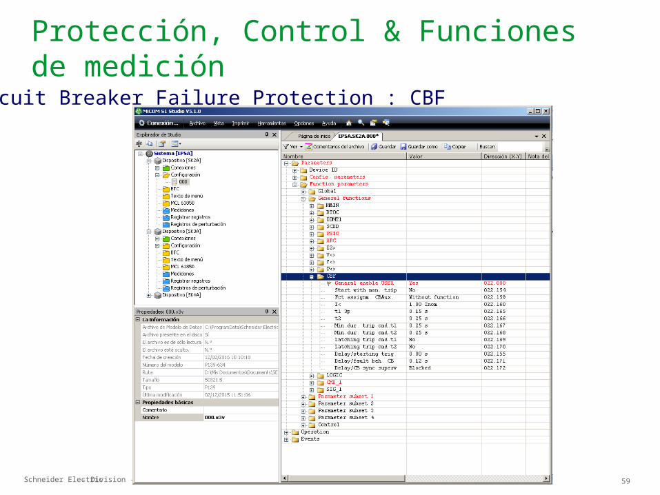
Protección, Control & Funciones de mediciónCircuit Breaker Failure Protection : CBF
Schneider Electric 60- Division - Name – Date
ASC
Automatic synchronism check
Protección, Control & Funciones de medición
Schneider Electric 61- Division - Name – Date
Protección, Control & Funciones de medición
V< >
Time - Voltage Protection
Schneider Electric 62- Division - Name – Date
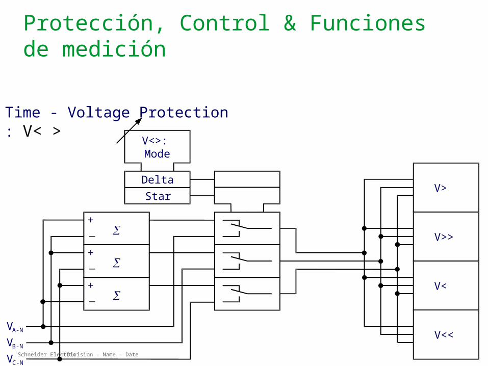
Protección, Control & Funciones de medición
V<>:Mode
DeltaStar V>
V>>
V<
V<<VA-N
VB-N
VC-N
+
+
+
Time - Voltage Protection : V< >
Schneider Electric 63- Division - Name – Date
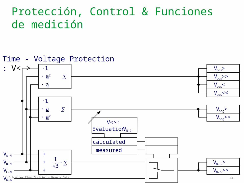
Protección, Control & Funciones de medición
VA-N
VB-N
VC-N
VN-G
V<>:Evaluation VN-G
calculatedmeasured
· ++
· a· a2
·1
· a· a2·1
VN-G>>VN-G>
Vneg>>Vneg>
Vpos>>Vpos>
Vpos<<Vpos<
13+
Time - Voltage Protection : V< >
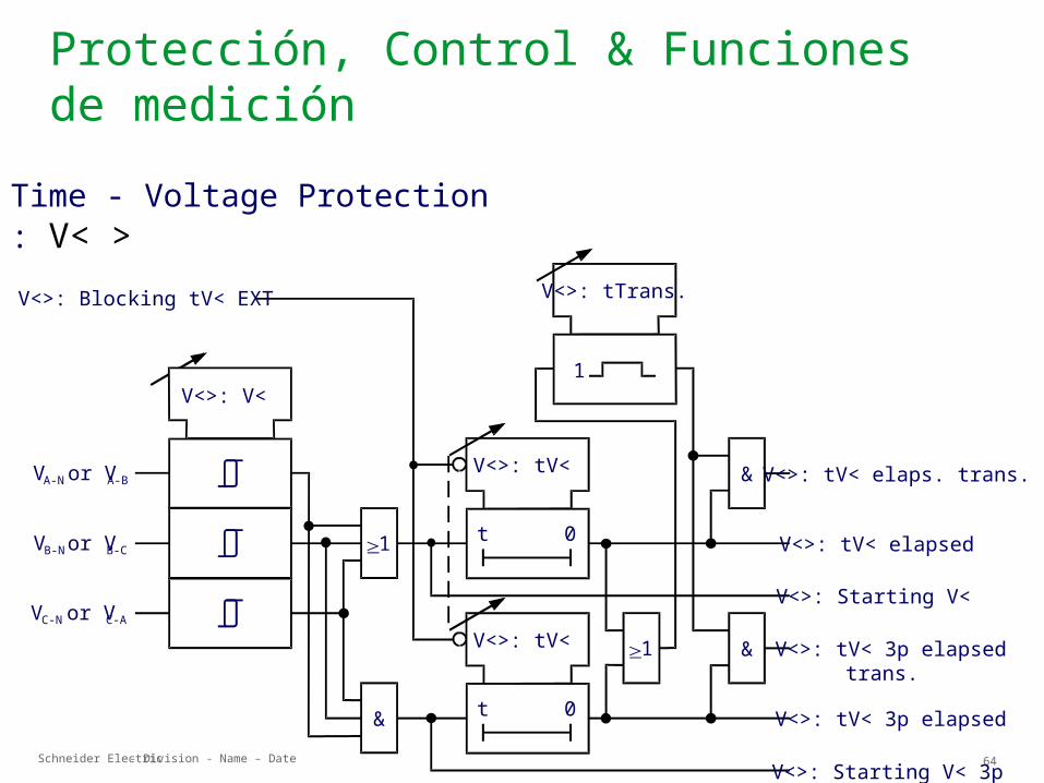
Schneider Electric 64- Division - Name – Date
Protección, Control & Funciones de medición
VA-N or VA-B
V<>: V<
VB-N or VB-C
VC-N or VC-A
1
V<>: Blocking tV< EXT
V<>: tV<
0t
V<>: tV<
0t
V<>: tTrans.
1
&
&
&
1
V<>: tV< elaps. trans.
V<>: tV< elapsed
V<>: Starting V<
V<>: tV< 3p elapsedtrans.
V<>: tV< 3p elapsed
V<>: Starting V< 3p
Time - Voltage Protection : V< >
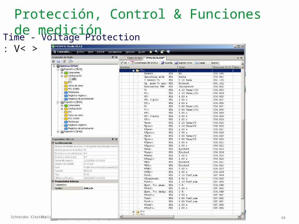
Schneider Electric 65- Division - Name – Date
Protección, Control & Funciones de mediciónTime - Voltage Protection : V< >
Schneider Electric 66- Division - Name – Date
Protección, Control & Funciones de medición
LO G IC
Programmable Logic
Schneider Electric 67- Division - Name – Date
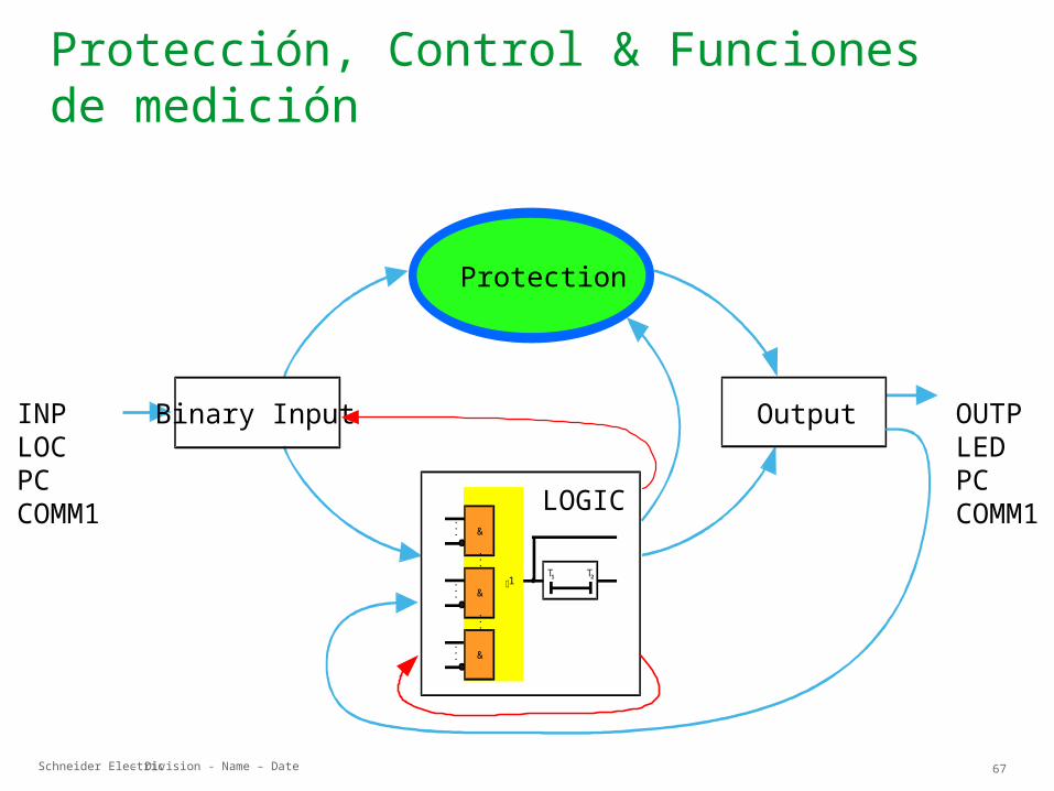
Protección, Control & Funciones de medición
......
...
......
&
&
&
1T1 T2
Protection
Binary Input Output
LOGIC
INPLOCPCCOMM1
OUTPLEDPCCOMM1
Schneider Electric 68- Division - Name – Date
Protección, Control & Funciones de medición
ControlControl
Schneider Electric 69- Division - Name – Date
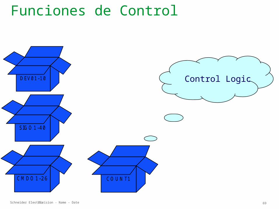
D EV01-10 Control Logic
SIG O 1-40
C M D O 1-26 C O U N T1
Funciones de Control
Schneider Electric 70- Division - Name – Date
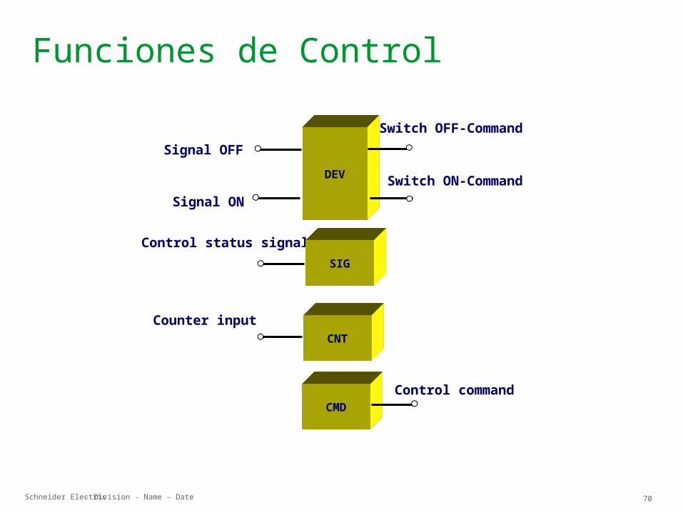
Funciones de Control
DEV
CMDControl command
Control status signal
Signal OFF
Signal ON
Switch OFF-Command
Switch ON-Command
CNTCounter input
SIG
Schneider Electric 71- Division - Name – Date
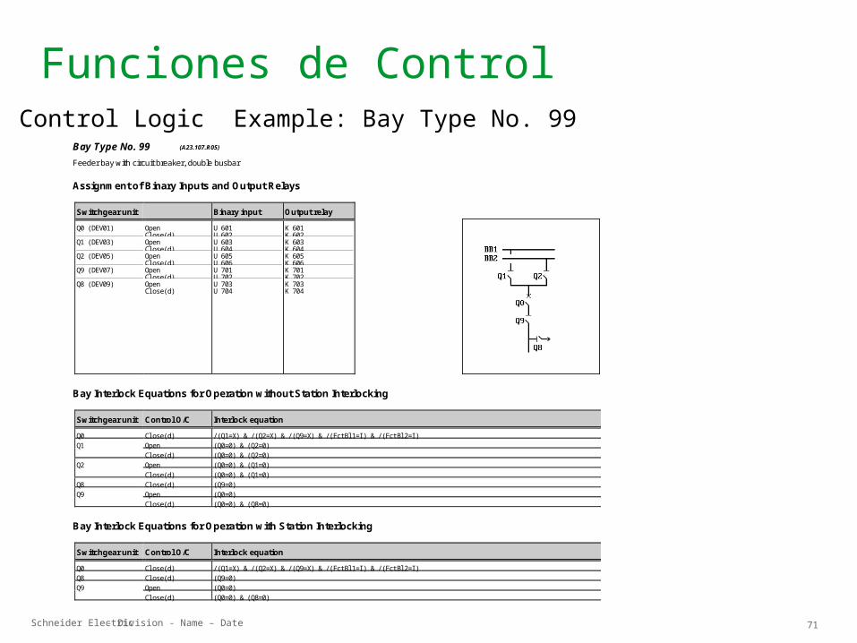
Funciones de Control
Bay Type No. 99 (A23.107.R05)
Feeder bay with circuit breaker, double busbar
Assignment of Binary Inputs and Output Relays
Switchgear unit Binary input Output relay
Q0 (DEV01) Q1 (DEV03) Q2 (DEV05) Q9 (DEV07) Q8 (DEV09)
OpenCl ose(d) OpenCl ose(d) OpenCl ose(d) OpenCl ose(d) OpenCl ose(d)
U 601U 602 U 603U 604 U 605U 606 U 701U 702 U 703U 704
K 601K 602 K 603K 604 K 605K 606 K 701K 702 K 703K 704
Bay Interlock Equations for Operation without Station Interlocking
Switchgear unit Control O/C Interlock equation
Q0 Cl ose(d) / (Q1=X) & / (Q2=X) & / (Q9=X) & / (FctBl 1=I ) & / (FctBl 2=I )Q1 Open (Q0=0) & (Q2=0)
Cl ose(d) (Q0=0) & (Q2=0)Q2 Open (Q0=0) & (Q1=0)
Cl ose(d) (Q0=0) & (Q1=0)Q8 Cl ose(d) (Q9=0)Q9 Open (Q0=0)
Cl ose(d) (Q0=0) & (Q8=0)
Bay Interlock Equations for Operation with Station Interlocking
Switchgear unit Control O/C Interlock equation
Q0 Cl ose(d) / (Q1=X) & / (Q2=X) & / (Q9=X) & / (FctBl 1=I ) & / (FctBl 2=I )Q8 Cl ose(d) (Q9=0)Q9 Open (Q0=0)
Cl ose(d) (Q0=0) & (Q8=0)
Control Logic Example: Bay Type No. 99
Schneider Electric 72- Division - Name – Date
Funciones de Control
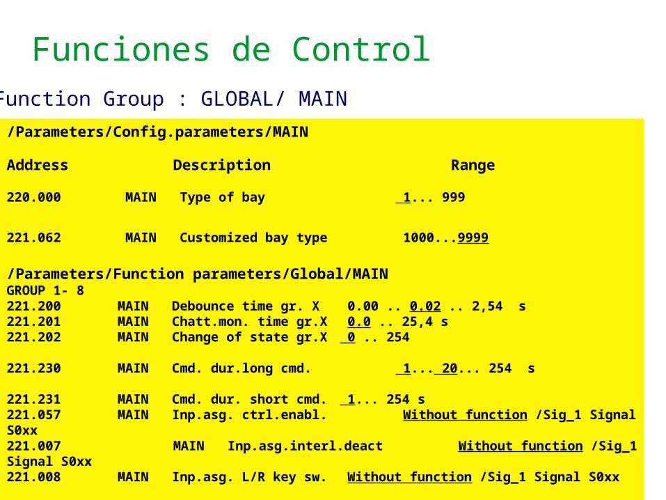
/Parameters/Config.parameters/MAIN
Address Description Range
220.000 MAIN Type of bay 1... 999 221.062 MAIN Customized bay type 1000...9999 /Parameters/Function parameters/Global/MAINGROUP 1- 8221.200 MAIN Debounce time gr. X 0.00 .. 0.02 .. 2,54 s221.201 MAIN Chatt.mon. time gr.X 0.0 .. 25,4 s221.202 MAIN Change of state gr.X 0 .. 254
221.230 MAIN Cmd. dur.long cmd. 1... 20... 254 s 221.231 MAIN Cmd. dur. short cmd. 1... 254 s221.057 MAIN Inp.asg. ctrl.enabl. Without function /Sig_1 Signal S0xx 221.007 MAIN Inp.asg.interl.deact Without function /Sig_1 Signal S0xx 221.008 MAIN Inp.asg. L/R key sw. Without function /Sig_1 Signal S0xx 221.065 MAIN Auto-assignment I/O No/Yes 221.061 MAIN Ctrl.point el. ctrl. Remote/Local 221.063 MAIN W. ext. cmd. termin. No/Yes 221.010 MAIN Inp.assign. tripping Without function /Sig_1 Signal S0xx
Function Group : GLOBAL/ MAIN

Schneider Electric 73- Division - Name – Date
Funciones de Control
ILO C K
Interlocking Logic
Schneider Electric 74- Division - Name – Date
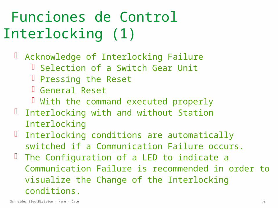
Funciones de Control Interlocking (1)
Acknowledge of Interlocking Failure Selection of a Switch Gear Unit Pressing the Reset General Reset With the command executed properly
Interlocking with and without Station Interlocking Interlocking conditions are automatically switched if a
Communication Failure occurs. The Configuration of a LED to indicate a Communication
Failure is recommended in order to visualize the Change of the Interlocking conditions.
Schneider Electric 75- Division - Name – Date
Protección, Control & Funciones de medición
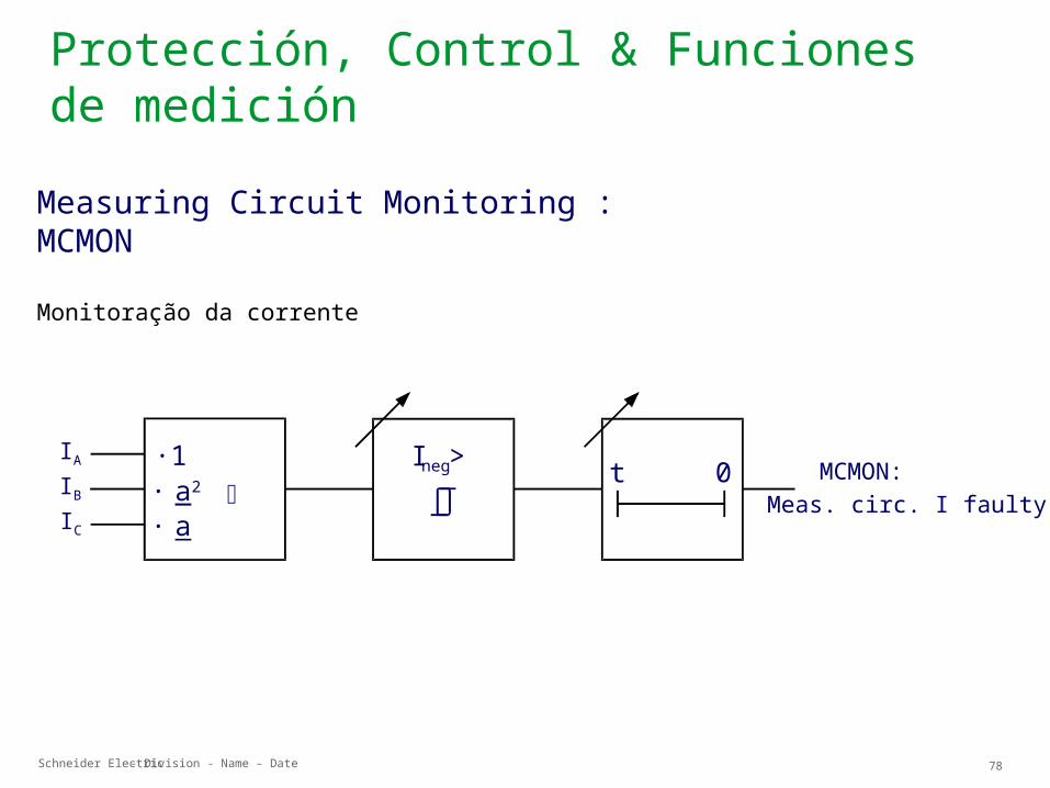
M C M O N
Measuring Circuit Monitoring
Schneider Electric 76- Division - Name – Date
Protección, Control & Funciones de medición
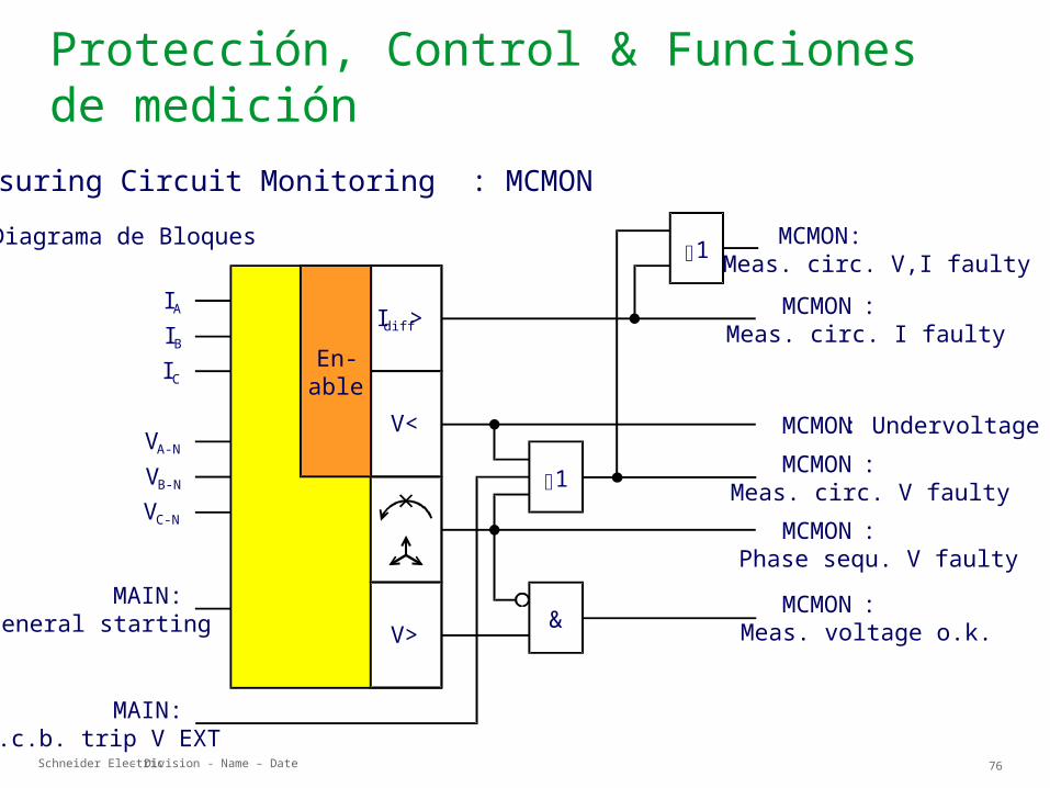
Diagrama de Bloques
IAIBIC
MCMON:Meas. circ. V,I faulty
MAIN:General starting
VA-N
VB-N
VC-N
MCMON:Meas. circ. I faulty
MCMON: UndervoltageMCMON:
Meas. circ. V faultyMCMON:
Phase sequ. V faultyMCMON:
Meas. voltage o.k.
MAIN:M.c.b. trip V EXT
I diff>
V<
V>
En-able
&
1
1
Measuring Circuit Monitoring : MCMON
Schneider Electric 77- Division - Name – Date
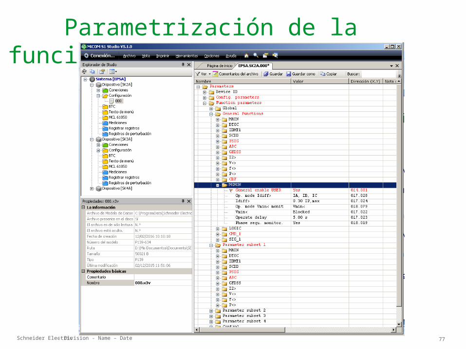
Parametrización de la función MCMON
Schneider Electric 78- Division - Name – Date
Protección, Control & Funciones de medición
Ineg>IA
IBIC
·1
· a· a 2 MCMON:
Meas. circ. I faultyt 0
Measuring Circuit Monitoring : MCMON
Monitoração da corrente
Schneider Electric 79- Division - Name – Date
Protección, Control & Funciones de medición
AplicaciónAplicación
Schneider Electric 80- Division - Name – Date
Protección, Control & Funciones de medición
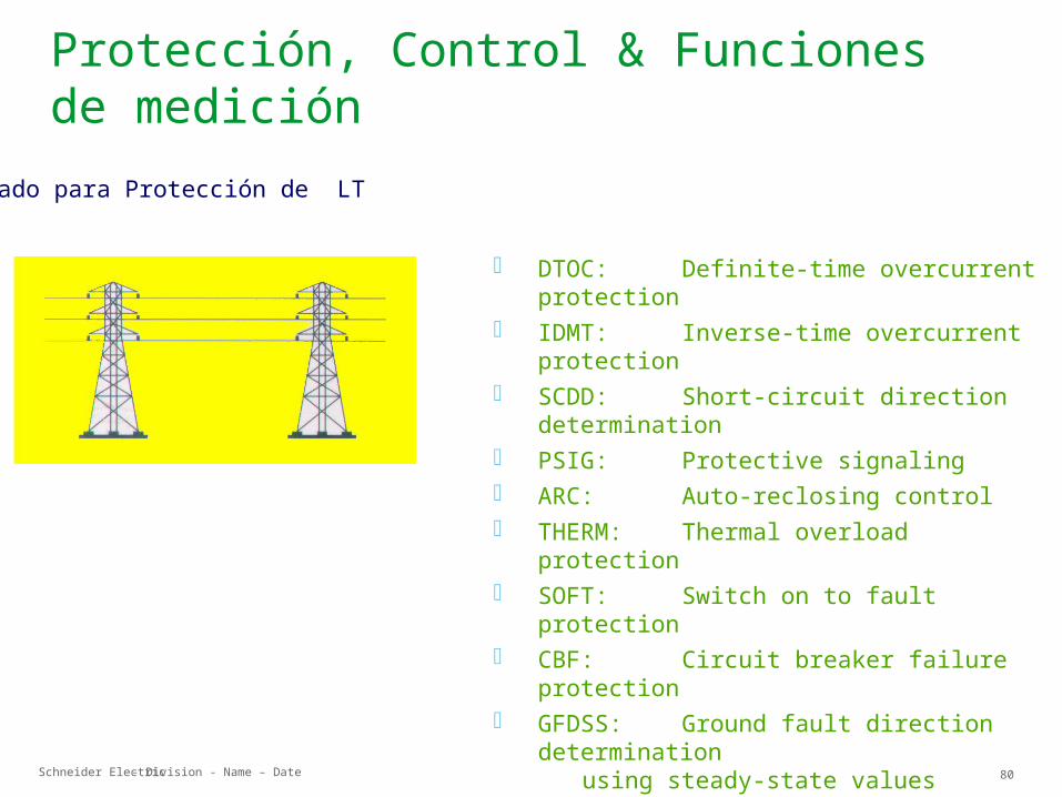
Usado para Protección de LT
DTOC: Definite-time overcurrent protection
IDMT: Inverse-time overcurrent protection
SCDD: Short-circuit direction determination
PSIG: Protective signaling ARC: Auto-reclosing control THERM: Thermal overload protection SOFT: Switch on to fault protection CBF: Circuit breaker failure
protection GFDSS: Ground fault direction
determinationusing steady-state values
TGFD: Transient ground fault direction
determination LIMIT: Limit value monitoring
Schneider Electric 81- Division - Name – Date
Protección, Control & Funciones de medición
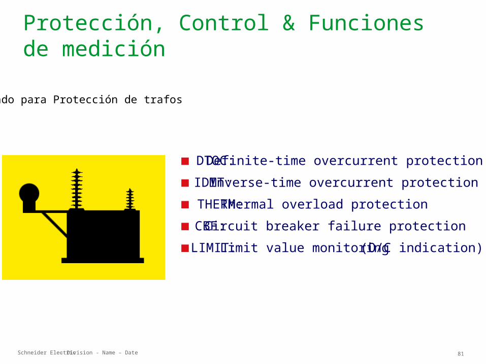
DTOC: IDMT: THERM: CBF: LIMIT:
Definite-time overcurrent protectionInverse-time overcurrent protectionThermal overload protectionCircuit breaker failure protectionLimit value monitoring (O/C indication)
Usado para Protección de trafos
Schneider Electric 82- Division - Name – Date
Protección, Control & Funciones de medición
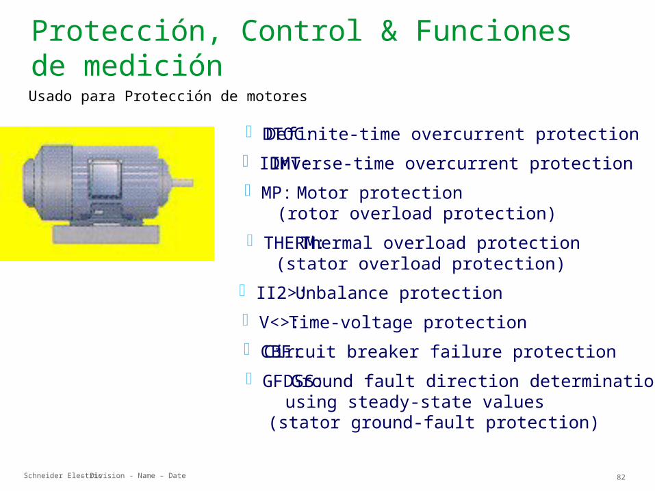
DTOC: IDMT: MP:
THERM:
I I2>: V<>: CBF: GFDSS:
Definite-time overcurrent protectionInverse-time overcurrent protection
Motor protection(rotor overload protection) Thermal overload protection(stator overload protection)Unbalance protectionTime-voltage protectionCircuit breaker failure protection Ground fault direction determinationusing steady-state values
(stator ground-fault protection)
Usado para Protección de motores
Schneider Electric 83- Division - Name – Date
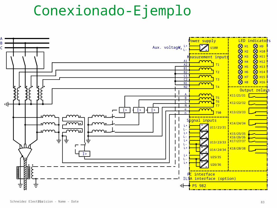
Conexionado-Ejemplo
Power supply
PC interfaceILSA interface (option)
Signal inputs
Measurement inputs
LED indicators
Output relays
ABC Aux. voltage VA
A1A2B1B2C1C2N1N2
ABCNen
L+ U100
K11/21/31
K12/22/32
K13/23/33
K14/24/34
K15/25/35K16/26/36K17/27/37
K18/28/38
H1H2H3H4H5H6H7H8
T1
T2
T3
T4
L-
L+ U11/21/31L-
T5T6T7
H9H10H11H12H13H14H15H16
U13/23/33
U14/24/34
U25/35
U26/36
L+L-L+L-L+
L+L-L+
T90I> I> I>
I>
PS 982