
PK-GWA Final Report Bengawan Solo... · 2019-10-24 · B737-300 PK-GWA Bengawan Solo River, Serenan...
54
KNKT/02.02/06.01.33 N N A A T T I I O O N N A A L L T T R R A A N N S S P P O O R R T T A A T T I I O O N N S S A A F F E E T T Y Y C C O O M M M M I I T T T T E E E E AIRCRAFT ACCIDENT REPORT PT. Garuda Indonesia GA421 B737-300 PK-GWA Bengawan Solo River, Serenan Village, Central Java 16 January 2002 NATIONAL TRANSPORTATION SAFETY COMMITTEE DEPARTMENT OF COMMUNICATIONS REPUBLIC OF INDONESIA 2006
Transcript of PK-GWA Final Report Bengawan Solo... · 2019-10-24 · B737-300 PK-GWA Bengawan Solo River, Serenan...

KNKT/02.02/06.01.33
NNAATTIIOONNAALL TTRRAANNSSPPOORRTTAATTIIOONN SSAAFFEETTYY CCOOMMMMIITTTTEEEE AIRCRAFT ACCIDENT REPORT
PT. Garuda Indonesia GA421 B737-300 PK-GWA Bengawan Solo River, Serenan Village, Central Java 16 January 2002
NATIONAL TRANSPORTATION SAFETY COMMITTEE DEPARTMENT OF COMMUNICATIONS REPUBLIC OF INDONESIA2006


When the Committee makes recommendations as a result of its investigations or research, safety is its
primary consideration. However, the committee fully recognizes that the implementation of
recommendations arising from its investigations will in some cases incur a cost to the industry.
Readers should note that the information in NTSC reports is provided to promote aviation safety: in no
case is it intended to imply blame or liability.
This report has been prepared based upon the investigation carried out by the National Transportation Safety Committee in accordance with Annex 13 to the Convention on International Civil Aviation, UU
No.15/1992 and PP No. 3/2001.
This report was produced by the National Transportation Safety Committee (NTSC), Gd. Karsa Lt.2 Departemen Perhubungan dan Telekomunikasi, Jalan Medan Merdeka Barat 8 JKT 10110 Indonesia.
Readers are advised that the Committee investigates for the sole purpose of enhancing aviation safety. Consequently, Committee reports are confined to matters of safety significance and maybe misleading if used for any other purpose.
As NTSC believes that safety information is of greatest value if it is passed on for the use of others, readers are encouraged to copy or reprint for further distribution, acknowledging NTSC as the source.


i
CONTENTS
CONTENTS 1-1
LIST OF APPENDIXES IV
LIST OF FIGURES V
GLOSSARY OF ABBREVIATIONS VII
SYNOPSIS 1
1 FACTUAL INFORMATIONS 3
1.1 History of Flight 3
1.2 Injuries to Persons 4
1.3 Damage to Aircraft 4
1.4 Other Damage 4
1.5 Personnel Information 4
1.5.1 Cockpit Crew 4 1.5.1.1 Pilot-in-Command 4 1.5.1.2 First Officer 5
1.5.2 Cabin Crew 5
1.6 Aircraft Information 5
1.6.1 Aircraft Data 5
1.6.2 Engine Data 6
1.6.3 Auxiliary Power Unit Data 6
1.6.4 Battery 6
1.7 Meteorological Information 7
1.8 Aids to Navigation 8
1.9 Communications 8
1.10 Aerodrome Information 8
1.11 Flight Recorders 8
1.11.1 Flight Data Recorder 8
1.11.2 Cockpit Voice Recorder 8

ii
1.12 Wreckage and Impact Information 8
1.13 Medical and Pathological Information 10
1.14 Fire 10
1.15 Survival Aspects 10
1.15.1 General 10
1.15.2 Evacuation 11
1.16 Test and Research 12
1.16.1 Aircraft Flight Path from ATC Radar 12
1.16.2 DFDR & CVR readout 13
1.16.3 Engines teardown and component examinations 15
1.16.4 Electrical Components Tests 15
1.16.5 Nose Radome 18
1.16.6 Airborne Weather Radar 19 1.16.6.1 Weather Radar Description 19 1.16.6.2 Weather penetration using Weather Radar 19 1.16.6.3 Weather Avoidance Within Confined Airspace 19
1.17 Organizational and Management Information 21
1.18 Other Information 22
1.18.1 Previous CFM56 weather induced flame out 22
1.18.2 CFM56-3 Water & Hail Capabilities 22
2 ANALYSIS 25
2.1 Encounter with Weather 25
2.2 Engines Flame Out 26
2.2.1 Engine capability 26
2.2.2 Environment 27
2.3 Restart Failure 28
2.3.1 Environment 29
2.3.2 Re-Start Procedure 29
2.3.3 Ignition System 29
2.3.4 Hardware Condition 30
iii
2.4 Battery 30
2.5 Weather Avoidance Within Confined Airspace 30
2.6 Weather Penetration Technique using weather radar 31
3 CONCLUSIONS 33
3.1 Finding 33
4 RECOMMENDATIONS 35
REFERENCES 36

iv
LIST OF APPENDIXES
Appendix A. Chronology of the flight based on ATC report
Appendix B. DFDR PLOTS
Appendix C. Table of in-flight engine flame out occurrences due to heavy rain/hail

v
LIST OF FIGURES
Figure 1 Damage to the aircraft 4
Figure 2 NOAA cloud coverage 7
Figure 3 Wreckage location 10
Figure 4 Interior Airplane Configurations and Occupant Injuries Map 11
Figure 5 Typical flight paths of previous flights 13
Figure 6 Damage to the battery 16
Figure 7 Linkage between cells no 11 and 12 (high temp sensor mounting) 17
Figure 8 Cell no 12 (left) showed no electrolyte as compared to the cell no 13 (right) 17
Figure 9 Details of damages on the nose radome. 18
Figure 10 Shows the actual flight track flown (as a black line), and part of the air way W-16 from Lasem, W-17 N Purwo and Solo (as White line) 20
Figure 11 Purwo one alfa arrivals 20
Figure 12 Ground track of previous flight 21
Figure 13 Garuda Indonesia Airline Organization Chart 22
Figure 14 Plot of the recorded sound intensity prior to the engine flame out 28
Figure 15 NOAA cloud coverage inside Military Restricted Area 31

vi

vii
GLOSSARY OF ABBREVIATIONS ATC : Air Traffic Control APP : Approach APU : Auxiliary Power Unit AAIB : Aircraft Accident Investigation Bureau Cb : Cumulonimbus CSN : Cycle Since New CVR : Cockpit Voice Recorder DFDR : Digital Flight Data Recorder FDR : Flight Data Recorder FLT : Flight FL : Flight Level Ft : Feet GCU : Generator Control Unit GPWS : Ground Proximity Warning System Kts : Knots MSSR : Mono-pulse Secondary Surveillance Radar NDB : Non Directional Beacon NOAA : National Oceanic Atmospheric Administration NTSB : National Transportation Safety Board NTSC : National Transportation Safety Committee PIC : Pilot In Command PSR : Primary Surveillance Radar P/N : Part Number SIGMET : Significant Meteorological S/N : Serial Number TSN : Time Since New UTC : Universal Time Coordinate ATC : Air Traffic Control APP : Approach APU : Auxiliary Power Unit AAIB : Aircraft Accident Investigation Bureau Cb : Cumulonimbus CSN : Cycle Since New CVR : Cockpit Voice Recorder DFDR : Digital Flight Data Recorder FDR : Flight Data Recorder FLT : Flight FL : Flight Level Ft : Feet GCU : Generator Control Unit GPWS : Ground Proximity Warning System Kts : Knots MSSR : Mono-pulse Secondary Surveillance Radar NDB : Non Directional Beacon NOAA : National Oceanic Atmospheric Administration

viii
NTSB : National Transportation Safety Board NTSC : National Transportation Safety Committee PIC : Pilot In Command PSR : Primary Surveillance Radar P/N : Part Number SIGMET : Significant Meteorological S/N : Serial Number TSN : Time Since New UTC : Universal Time Coordinate VMC : Visual Meteorological Conditions

1
SYNOPSIS On January 16, 2002, a Boeing 737-300, registration PK-GWA, was on a
scheduled commercial flight from Ampenan at 08:32 UTC with 54 passenger inboard and 6 crews to Yogyakarta. While descending through 19,000 ft, the aircraft entered severe cumulonimbus cloud formations with turbulence and heavy rain and hail. The excessive water/hail ingestion by the engines caused loss of power on both engines. The relight attempts on both engines failed since they were executed while the aircraft was still encountering heavy precipitation which turned out beyond engine certified capabilities. The flight crew attempted at least two engine relight, and one attempt of APU start. During the APU start was initiated, the crew noted total electrical power loss in the aircraft. A forced landing then was executed, and the aircraft ditched into the waters of the Bengawan Solo River, Central Java at approximately 09:24 UTC.
One flight attendant was fatally injured, one flight attendant and twelve passengers suffered serious injuries, other passengers, flight crew and two flight attendants were uninjured.
The investigation was carried out by NTSC with the assistance of NTSB and participation of aircraft, aircraft component and engine manufacturers. The FDR and CVR readout was performed at AAIB facility.

2

3
1 FACTUAL INFORMATIONS 1.1 History of Flight
On January 16, 2002, at approximately 09:24 UTC, a Boeing 737-300, PK-GWA, ditched into the waters of the Bengawan Solo River, Central Java during a forced landing, following loss of power on both engines as the aircraft was descending through 19,000 ft. The dual engine flame out occurred shortly after the aircraft entered severe cumulonimbus cloud formations with turbulence and heavy rain and ice.
The aircraft, owned and operated by PT Garuda Indonesia as Flight GA 421, had departed Ampenan at 08:32 UTC, on a regular scheduled commercial flight with destination Yogyakarta.
At departure VMC conditions prevailed. The flight from Ampenan was reported uneventful until its arrival in the Yogyakarta area. The crew stated that they observed cumulonimbus cloud formations on their weather radar.
The aircraft descended from cruise altitude of 31,000 ft to 28,000ft as instructed by BALI ATC at 09.08 UTC due to traffic on eastbound at FL290. As they began their descent from FL 280 at 09.13 UTC, prior to entering the clouds at 23,000 feet, the crew noted at the radar screen red cells with two green and yellow areas to the left and right of their intended flight path. The Pilot Flying decided to take the left opening above PURWO NDB.
The flight crew prepared to enter turbulence by setting turbulence speed at 280 knots, seatbelt on, engine ignitions on FLT and anti-ice on. Then the Pilot Flying requested to BALI ATC to descend to FL 190 and was cleared by Semarang APP at 09.13 UTC.
Shortly after the aircraft entered the area covered by Cumulonimbus cells, the crew noted severe turbulence and heavy precipitation. According to the flight crew interview, the crew noted aircraft electrical power generators loss and they were only having primary engine instrument indications and captain flight instruments, which finally identified both engines flame-out.
While in the precipitation, the flight crew attempted at least two engine relights, and one attempt of APU start. As the APU start was initiated, the crew noted total electrical loss of the aircraft.
The aircraft descended into VMC conditions at about 8,000 ft altitude. The PIC spotted the Bengawan Solo River and decided to land the aircraft on the river. The crew announced to the flight attendant to prepare emergency landing procedure. The aircraft landed successfully between two iron bridges in the upstream direction, and came to a stop with its nose pointing to the right of the landing path. The aircraft settled down on its belly, with the wings and control surfaces largely intact, and was partially submerged.
The evacuation following the landing was successful. Twelve passengers suffered injuries, the flight crew and two flight attendants were uninjured, one flight attendant suffered serious injuries, and another flight attendant was found in the waters of the river and fatally injured.

1.2 Injuries to Persons Injuries Crew Passengers Others TOTAL
Fatal 1 - - 1 Serious 1 12 - 13
Minor/ None 4 42 - 46 TOTAL 6 54 - 60
1.3 Damage to Aircraft The aircraft was damaged beyond repair and is considered a total loss.
Figure 1 Damage to the aircraft
1.4 Other Damage No third party experienced damage except pollution to the river.
1.5 Personnel Information
1.5.1 Cockpit Crew
1.5.1.1 Pilot-in-Command Gender : Male Date of birth : 29 March 1957 Nationality : Indonesia Marital status : Married Date of joining company : 16 March 1980 License : ATPL 2582 Validity period of license : 20 March 2002 Type rating : B-737 (300/400/500) Instrument rating : 16 February 2001 Medical certificate : 20 March 2001 Date of last medical : 20 September 2001 Last line check : 06 May 2000 Last proficiency check : 16 August 2001
4

5
1.5.1.2
FLIGHT TIME Total time : 14,020:30 hrs This make & model : 5,086:30 hrs Last 90 Days : 193:33 hrs Last 60 Days : 109:23 hrs Last 24 Hours : 4:10 hrs This flight : 52 min
First Officer
Gender : Male Date of birth : 28 April 1955 Nationality : Indonesia Marital status : Married Date of joining company : 16 September 1982 License : ATPL 1906 Validity period of license : 11 March 2002 Type rating : B-737 (300/400/500) Instrument rating : 18 April 2001 Medical certificate : 11 March 2001 Date of last medical : 11 September 2001 Last line check : 5 July 1998 Last proficiency check : 18 October 2001
FLIGHT TIME Total time : 7,137:24 hrs Last 90 Days : 152:00 hrs Last 60 Days : 89:11 hrs Last 24 Hours : 4:10 hrs This flight : 52 min
1.5.2 Cabin Crew There were four flight attendants on board the aircraft, one male and three females. All the attendants’ licenses were valid at the time of the accident.
1.6 Aircraft Information
1.6.1 Aircraft Data Registration Mark : PK-GWA Manufacturer : Boeing Country of Manufacturer : USA Type/ Model : B737-3Q8 Serial Number : 24403 Date of manufacture : 1989

6
Certificate of Airworthiness : 1417 Issued : 12 May 2001 (valid until 11 May 2002) Certificate of Registration : 1417 Issued : 25 April 2001 (valid until 24 April 2002) Category : Transport Crew (Cockpit/Cabin) : 2 Cockpit crew and 4 Cabin crew Time Since New : 28.141:29 (as 14-01-2002) Cycles Since New : 24.607 (as 14-01-2002) Last Minor Inspection : (A check) 8 December 2001
1.6.2 Engine Data
Engine Type : Turbofan Manufacturer : CFM International Serial Number Engine #1 : 856721 Type/ Model : CFM 56-3B1 Installed : 20 September 2000 TSN : 19.114:19 (as 14-01-2002) CSN : 14.285 (as 14-01-2002)
Serial Number Engine #2 : 857706 Type/ Model : CFM 56-3B1 Installed : 16 November 2001 TSN : 19.729:53 (as 14-01-2002) CSN : 14.709 (as 14-01-2002)
1.6.3 Auxiliary Power Unit Data
Manufacturer : Garrett Model : GTC P85-129H Serial Number : P60580 Installed : 24 December 2000 TSN : 27134 (as 14-01-2002)
1.6.4 Battery The battery is a wet Ni-Cad battery with KOH electrolyte. The steady state voltage for a fully charged battery is 24 Volt.
Manufacturer : SAFT
Model : 60B40017-7/A1 Serial Number : 636 Last Installed : 12 December 2001 Time Since Last Installed : 204 Hrs Time since Last Shop Visit : 34704 Hrs TSN : 34908 Hrs

1.7 Meteorological Information NOAA clouds coverage 14 minutes prior to the emergency landing is shown in Figure 2.
Figure 2 NOAA cloud coverage
The NOAA satellite cloud picture (at 09.07 UTC) shows the active super cell of the Cumulonimbus (Cb) Cloud along the track. January is the peak season over most of the Java Island, in which high frequency activity of the convective cloud is a common weather condition.
On 16 January 2002, the satellite observed an active super cell over the area as indicated by NOAA Cloud Coverage in Figure 2. As the cell of Cb. was active over land during afternoon hours, the mature stage of Cb. cloud would disturb the aircraft. As forecasted over the Solo/Adi Sumarmo Airport between 09.00 – 12.00 UTC would be temporary rain showers and thunderstorm. However, no weather information was made available about adverse weather condition along the airplane track (SIGMET).
As the super cell of Cb. cloud commonly has strong up and down motion causing turbulence, electrical storm (atmospheric electricity) and icing condition, which may result in super-cooled water droplets which could be hazardous to aircraft going through. Those three types of adverse weather condition would be the main disturbance. The existence of the super cooled water droplets is the first disturbance and supported by other disturbances such as up- and down-ward movement (strong turbulence) and electrical storm. These features are common environmental condition and situation in the lower atmosphere (troposphere) when the Cb. cloud activity in terms of super cell has been observed.
7
8
1.8 Aids to Navigation Not relevant.
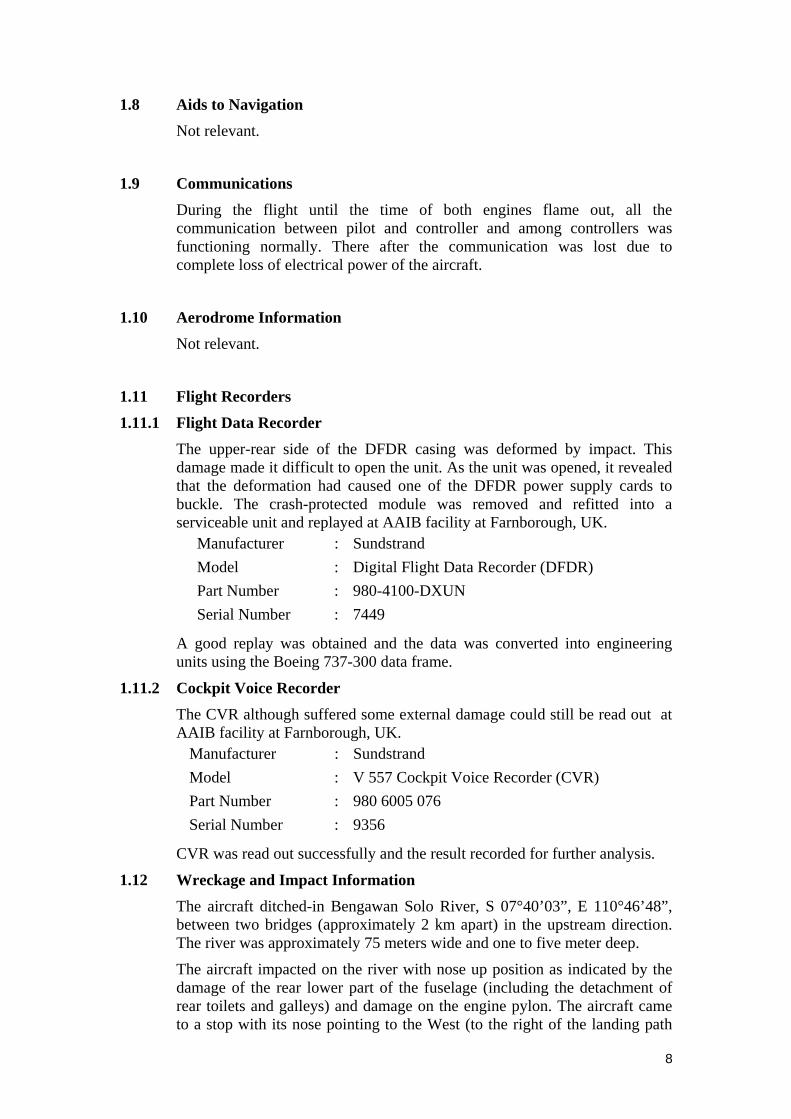
1.9 Communications During the flight until the time of both engines flame out, all the communication between pilot and controller and among controllers was functioning normally. There after the communication was lost due to complete loss of electrical power of the aircraft.
1.10 Aerodrome Information Not relevant.
1.11 Flight Recorders
1.11.1 Flight Data Recorder The upper-rear side of the DFDR casing was deformed by impact. This damage made it difficult to open the unit. As the unit was opened, it revealed that the deformation had caused one of the DFDR power supply cards to buckle. The crash-protected module was removed and refitted into a serviceable unit and replayed at AAIB facility at Farnborough, UK.
Manufacturer : Sundstrand Model : Digital Flight Data Recorder (DFDR) Part Number : 980-4100-DXUN Serial Number : 7449
A good replay was obtained and the data was converted into engineering units using the Boeing 737-300 data frame.
1.11.2 Cockpit Voice Recorder The CVR although suffered some external damage could still be read out at AAIB facility at Farnborough, UK.
Manufacturer : Sundstrand Model : V 557 Cockpit Voice Recorder (CVR) Part Number : 980 6005 076 Serial Number : 9356
CVR was read out successfully and the result recorded for further analysis.
1.12 Wreckage and Impact Information The aircraft ditched-in Bengawan Solo River, S 07°40’03”, E 110°46’48”, between two bridges (approximately 2 km apart) in the upstream direction. The river was approximately 75 meters wide and one to five meter deep.
The aircraft impacted on the river with nose up position as indicated by the damage of the rear lower part of the fuselage (including the detachment of rear toilets and galleys) and damage on the engine pylon. The aircraft came to a stop with its nose pointing to the West (to the right of the landing path

9
which is South-ward and upstream), settled down on its belly with the wings and control surfaces largely intact and partially submerged.
The airframe suffered heavy damage at the bottom aft of the right hand cargo door. The airframe also was heavily damaged between the cockpit section bulkhead and the front wing spar bulkhead. The aircraft main frame structure showed skin buckling aft just in front of the vertical stabilizer. The nose landing gear and right hand main landing gear was found detached from their attachments, approximately 50 meters from the aircraft final rest.
The left hand aft lavatory and lower part of the aft galley were ripped apart from the aircraft and a large hole was found in the floor at the aft cabin section.
The damage of the aft fuselage section was due to impact on landing and its detached parts and components were found downstream. This suggested that the aircraft was on a pitch-up attitude during landing.
In the interior of the aircraft, seats were found detached from their fittings. All left hand side doors and emergency exits were unopened. The right hand forward door was found opened and the slide was deployed. The floor showed structural deformation. The floor aft of the cockpit door buckled and the floor on the aisle of the second row (business class) collapsed. The overhead bins were dislodged.
The leading edges of the horizontal stabilizers suffered light damage from impact with the river. The aircraft was inspected for hail damage and none was found, other than the damage to the radome noted below and in section 1.16.5. The flaps and slats were found on retracted position (clean configuration). Fuel tank in the left hand wing was found leaking due to impact, leaving 400 liters of fuel in the tank. There was 2800 liters of fuel left in the right hand wing fuel tank.
The radome paint was heavily eroded showing the composite structure. Damage examinations performed on the radome are discussed on the section 1.16.5.
The left engine was still attached to its pylon, while the right engine was detached from its pylon. Parts of the cowlings of both engines were not in place. There are signs of landing impact damage to the engines. Tests performed on the engines system are discussed on the section 1.16.3.
The APU and battery was found underwater about 4 weeks after the accident downstream approximately 300 meters from the aircraft, and the CVR was found approximately 200 meters from the aircraft. Test performed on the electrical components are discussed on the section 1.16.4. The APU inlet door was found closed (see picture).

Figure 3 Wreckage location
1.13 Medical and Pathological Information The fatally injured cabin crew was lacerated on her face, left part of the necks (i.e. fracture of the neck), fracture of the both upper arms, right femur, left lower leg, and all toes were missing.
The cabin crew death is presumably due to impact with the bottom of the river of the aircraft against the river.
1.14 Fire There were no signs of fire prior to or after the impact.
1.15 Survival Aspects
1.15.1 General
Ditching the aircraft into the river was considered by the crew to be the safest option for a forced landing. Fifty three occupants were safely evacuated to the river bank. One flight attendant who was seated at the aft jump-seat was found severely wounded on the river, and one another flight attendant was found fatally injured on the river
The aircraft was configured with 104 passenger seats; 22 in business class and 82 in economy class. An aft-facing, double-occupancy flight attendant jump-seat was located by the forward passenger door; an aft-facing, single occupancy flight attendant jump-seat was mounted behind the right-hand and left-hand aft lavatory. Figure 4 It shows the interior airplane configuration and the injuries sustained by the passengers and crewmembers according to the seat location.
10

Figure 4 Interior Airplane Configurations and Occupant Injuries Map
1.15.2 Evacuation After the aircraft came to a stop, the only exit available immediately was the forward service door, which was opened by the 2nd Flight Attendant, with the escape slide inflated automatically. The flight attendant stated that she did not expect to ditch on a river. The right-hand over-wing exit was opened and was assisted by a fisherman from the outside 15 minutes later, i.e. after the PIC allowed him to get close to the aircraft. The hatch was then positioned on the right-hand wing surface by the fisherman to be used to transport an injured passenger. The aft passenger and service doors could not be used due to structural deformation of the fuselage and also because the floor sections adjacent to the doors collapsed. The forward passenger door was also jammed. According to the flight attendants, the emergency exit lights on the walls were illuminated but they did not recall any lights/illumination on the
11

12
floor. According to the flight attendants and the passengers, there was no fire or smoke present in the cabin during the evacuation.
The flight crew had to kick open the cockpit door to get to the cabin and then assisted the passengers’ evacuation with the flight attendants who were seated on the forward jump-seats. The PIC then notified Garuda Operations Centre in Jakarta with his cellular phone. The flight attendants seated on the aft jump-seats could not assist with the passenger evacuation because they were pulled down out of the aircraft during the crash and one of whom sustained serious and fatal injuries.
Passengers in the economy class evacuated the aircraft through the right-hand over-wing exit. Some of the passengers did not evacuate the aircraft immediately; instead they tried to retrieve their personal belongings stowed in the overhead bins despite flight attendants’ commands to leave the luggage. Five of the six business class passengers were seriously injured and they had to be assisted by the flight attendants to evacuate through the forward service door.
The villagers from around the accident site helped the evacuation. The passengers and their personal belongings were temporarily sheltered in an empty house near the river before they were transported to the nearest hospitals (Dr. Oen hospital, Kasih Ibu Hospital). The seriously injured passengers were transported immediately to the nearest clinic by a pick-up car which was available near the accident site. Rescue team, local police, the air force, and Adi Sumarmo (Solo airport) staff, arrived on site a couple of hours after the crash, and the evacuation process of all passengers to the save location was completed approximately one hour after the aircraft crash.
1.16 Test and Research
1.16.1 Aircraft Flight Path from ATC Radar Results to reveal the aircraft flight path from ATC radar are as follows.
The radar set used in Yogyakarta APP is MSSR (Mono-pulse Secondary Surveillance Radar) type, a Thompson – Thales radar generation manufactured in 1995, but unfortunately the radar track records could not be copied to another media (i.e. floppy disk), and the track printer was not going normally, the flight path diagrams drawn on the map (see Figure 5) are the results of plotting positions data from the latitude and longitude data recorded on the FDR. The visual interpretation from the radar display replay was used to determine the track of the aircraft after the DFDR ceased recording.

Figure 5 Typical flight paths of previous flights
On the radar screen (at Yogyakarta APP) since the target appeared around 09.08 UTC the track of GIA-421 was normal, i.e. West bound. Starting at 09.20 UTC it went South bound. At 09.22 UTC it still showed a label of GIA-421F200S390, meaning that it was on FL200 descending by a ground speed of 390 knots. Then at 09.24 UTC the speed increased up to 410 knots, before the SSR target disappeared and faded out.
The PSR (Primary Surveillance Radar) showed the target moved fast in an unstable flight path. At 09.32 UTC the PSR target disappeared for few seconds then came back again at 09.33 UTC, which was the last time the PSR target showed.
09.22 UTC was the expected time for GIA-421 to report at PURWO point but the aircraft failed to report. At 09.23 UTC Semarang APP attempted to call GIA-421 two times but there was no answer. Semarang APP, then, performed intensive coordination with Yogyakarta APP to check GIA-421’s radar target on the screen. The target still appeared at that moment until 09.33 UTC. At 09.40 UTC, there was an emergency call from Solo informing Yogyakarta APP that a Garuda aircraft crashed in Serenan village ± 22 km South of Solo city.
1.16.2 DFDR & CVR readout The upper-rear side of the DFDR casing was deformed by impact. This damage made it difficult to open the unit. As the unit was opened, it revealed that the deformation had caused one of the DFDR power supply cards to buckle. The crash-protected module was removed and refitted into a serviceable unit and replayed at AAIB facility at Farnborough, UK.
A good replay was obtained and the data was converted into engineering units using the Boeing 737-300 data frame.
The data plots and listing for the last 250 seconds of the records are shown in Figure 4. The main points are:
1. The aircraft entered heavy turbulence (indicated by intense fluctuation on the vertical, lateral, and longitudinal acceleration) for approximately one and a half minutes before the recording stopped.
13

14
2. At entering the turbulence, the recording indicates water ingestion by the engines as the fuel flow increased from 600 lbs/h to as high as 770 lbs/h, before it went down to 510 lbs/h at the end of the recording. The presence of water in the core engines will increase the fuel required to keep engine N1 (fan rotation) at certain throttle setting.
3. Seven seconds before the end of the recording, the engines’ N1 and N2 decreased from the idle setting (40% for N1 and 70% for N2) simultaneously. The last readable data read 28 % for N1 and 49% for N2.
4. Recording shows that during the last phase of the recorded flight the crew used auto-pilot.
5. Recording shows that the Total Air Temperature before entering the turbulence was 11 °C and when entering turbulence was 7.5 °C.
The CVR had been immersed in water during the accident and for that reason the CVR was preserved in a container filled with water.
The recorder had suffered some external damage, which necessitated the external cover having to be cut.
When the tape deck was exposed it was apparent that water had leaked through to the tape deck.
The tape itself had “jumped” of its guide rollers and out of the end of tape sensor. A portion of the tape was wedged underneath the tape stack on the bottom reel. As a result, there was a damage of 20 cm length of tape, the tape was creased, but not broken. The tape was then re-spooled by hand onto a plastic reel, flattening out the creases and cleaning/drying the tape. The tape was replayed on an AAIB tape deck to which had been fitted with appropriate replay heads.
The recording from the four tracks was digitized. The cockpit area mike was the one that contained most of the information on the flight. The sound of rain hitting the fuselage, however, created tremendous amount of noise on the recording. Some efforts were made using frequency separator to eliminate the noise but to no avail. The frequency of the noise is the same as the frequency of the voice, therefore, reducing such noise would result reduction on the voice.
The recording revealed that the aircraft was in heavy precipitation (most likely a mix of rain and hail) for approximately one and a half-minute before the CVR stopped. The stoppage of the recording indicates that the CVR stopped due to loss of AC power. The sound database of AAIB revealed that the rain is heavier than the heaviest rain ever recorded (Doha case). However, it is to be noted that the quantitative comparison can not be carried out, as the aircraft in Doha – Qatar accident case was a B-727 aircraft.
GPWS activated at the last two second before the stoppage of CVR recording.
It is known that the fuel flow is affected by the amount of hail/water ingested into the engine.
An attempt was made to correlate sound energy level with the atmospheric hail/water content. This method had not been utilized before, and has not

15
been validated. The sound energy level was synchronized with the DFDR fuel flow data. The data shows reasonable correlation. Extrapolation from the sound energy level indicates that the level of hail/water content encountered by the aircraft at the time of engine flame out could have been as high as 18 grams of hail/m3 of air, depending on the size and density of the hail/grapple (smaller, more numerous hail/grapple will result in higher water density as compared to large, fewer hail/grapple).
1.16.3 Engines teardown and component examinations Engine inspection confirmed that all modifications concerning water/hail improvements were in place (elliptical spinner, cutback splitter, 12 VBV doors with scoop). Therefore, the engines are known to be able to sustain the certified hail ingestion the current FAA requirement is 10 g/m3 from 10,000 to 15,000 ft altitude.
Visual inspection of LPT, LPC, fan, and MEC revealed neither mechanical nor thermal damaged prior to the impact. Since the engines fan and cowl (and even the fragile oil cooling radiator) do not show any solid object damage anticipated if large size hail was present, it indicates that the aircraft encountered grapple/sleet (hail in phase between ice and water state).
The VBV actuation systems were tested functionally. The purpose of the test was to check whether failure in the VBV system could cause the hail/water to enter the engine core. The damage of the engine prevented precise determination of VSV and VBV rigging (some feedback cables and bracket were bent).
Fuel delivery system was tested and the result shows that the fuel delivery were normal.
The absence of over temperature signature on the LPT shows that there was no relight at high temperature. Nozzle sprayer, exciter, and igniter plugs were tested and the results were normal.
Therefore, engine teardown concluded that no abnormal conditions were found in the engine controlling system or engine hardware that would attribute to engine flameout or relight capability.
The details of the engines teardown and components test were reported in Reference 1.
Fuel taken from the wreckage was tested and the result was satisfactory.
1.16.4 Electrical Components Tests The focus of the electrical component test was the battery and its related components, since interviews indicated failure in the power system after engine relight attempt. The Generator Control Unit’s (GCU), battery charger and relays coded R39, R89, R325, R326, R355, and R1 were selected since their failure could affect the electrical power system performance. Failure in GCU, for example, could result in overcharging, which could weaken the battery. Failure in the battery charger, R39, R89, and R325 could result in failure to recharge the battery, meanwhile, failure in R326, R355, and R1 could give effect as if the battery was dead.
The GCUs and battery charger functional tests were carried out using B737 electrical component test rig at Boeing equipment quality analysis lab. The

engine # 1, # 2, and APU GCU functional tests revealed that the GCU’s functioned properly in controlling each generator output and in performing generator transfer. It was also confirmed that the diodes internal to the CGUs were not failed.
The battery charger was functionally tested with PK-GWA GCU’s installed in the rig. The result revealed that the battery charger functioned properly in charging the battery in the Recharge Mode and then switching into the constant voltage mode.
Battery manual and references stated that the Ni-Cad battery with KOH electrolyte voltage does not tell the condition of the battery. The steady state voltage for a fully charged battery is 24 Volt. An aging battery will deplete faster and will also have 22-24 indicated voltage. When the voltage drops bellow 20 Volt, which tells that the battery is dying and will deplete instantaneously.
The battery-discharging test was carried out with a lab battery since the PK-GWA battery was found to be incomplete, and some of its cells were contaminated with river water. The purpose of the test was to learn how the battery system behaves in the case resembling the emergency PK-GWA scenario.
The test scenario was to discharge the battery until the battery voltage indicator showed 22 V. The rig, then, will load the battery for 30 seconds with the standby bus, followed by 90 seconds with the standby bus and engine igniters, followed by another 30 seconds of standby bus load, and finally load the battery during 90 seconds by the standby bus, the engine igniters (remaining in flight position), and followed by the APU start.
The test showed that as soon as the second sequence (standby load + engine igniters’ load) was executed, the battery voltage went down very fast. Five seconds after the second sequence the battery voltage was depleted instantaneously to 12 V. The test was stopped as it is known that the battery is useless if the voltage was less than 18 V.
Therefore, the test concluded that the sequence as planned can not be completed if the battery voltage at the beginning is less than 22 V.
Figure 6 Damage to the battery
Battery examination found that the battery casing was damaged due to impact (see Figure 6), which caused mechanical damage on cells no 1 & 2. The examination also found that the thermostat sensor mounting (at the linkage between cells no 11 to 12) was found severely corroded and the sensor was missing. The metallurgical analysis showed that the corrosion was not caused by being submerged in river water, and therefore has
16

happened before the accident and the detachment of the sensor was not caused by mechanical force (see Figure 7).
Figure 7 Linkage between cells no 11 and 12 (high temp sensor mounting)
Figure 8 Cell no 12 (left) showed no electrolyte as compared to
the cell no 13 (right)
The highlight of the examination result was the cell no. 12, which was found to have very little electrolyte left although the KOH (Potassium Hydroxide) concentration level was calculated to be normal after the cell was re-conditioned. It meant that the electrolyte was spewing through the vent valve on the top of the cell (convective movement of KOH and water out of the cell), and not due to evaporation or electrolyze processes. It is to be noted that cell no. 12 is the newest cell in the battery, as it was installed in 1999, while the rest of the cells were installed in 1996. The position of the cell was in the hottest location of the battery, which is why the high temperature sensor is located in the linkage between cells 12 and 11.
The details of the electrical components test are in Reference 2. Boeing Commercial Airplanes. (February 27, 2003). E
Battery record review showed that the battery has been installed in this aircraft for duration of 204 flight hours. It had been stored in Yogyakarta station for 4 months (see Reference 4) and therefore, had been charged four times using 282 Activator. The charging procedure is in accordance with Reference 3. EI no. AG/24-30-0302.
17
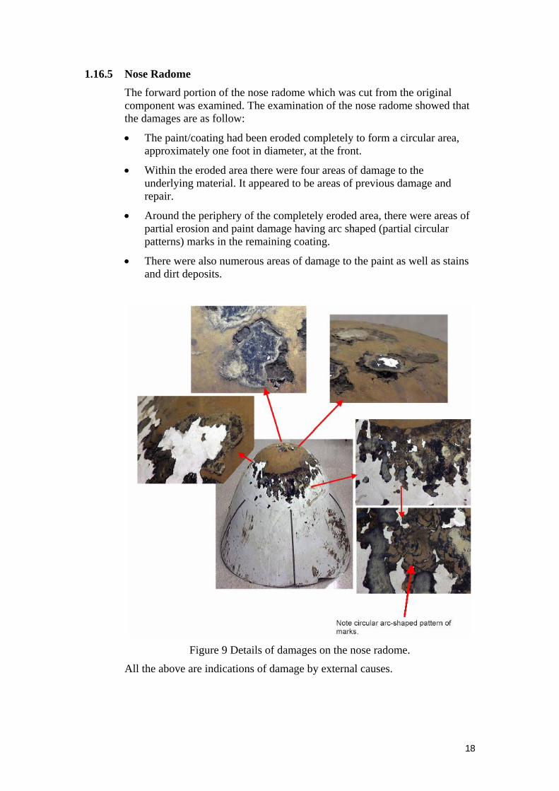
1.16.5 Nose Radome The forward portion of the nose radome which was cut from the original component was examined. The examination of the nose radome showed that the damages are as follow:
• The paint/coating had been eroded completely to form a circular area, approximately one foot in diameter, at the front.
• Within the eroded area there were four areas of damage to the underlying material. It appeared to be areas of previous damage and repair.
• Around the periphery of the completely eroded area, there were areas of partial erosion and paint damage having arc shaped (partial circular patterns) marks in the remaining coating.
• There were also numerous areas of damage to the paint as well as stains and dirt deposits.
Figure 9 Details of damages on the nose radome.
All the above are indications of damage by external causes.
18

19
1.16.6.1
1.16.6.2
1.16.6.3
1.16.6 Airborne Weather Radar
Weather Radar Description RADAR is simply an acronym for Radio Detecting and Ranging, by transmitting short pulses of radio energy, then listening for the backscatter, or “echo” the system detects and displays a range to any objects which present a reflective surface to that pulse of energy.
When used to detect objects in the atmosphere, it detects and displays range only to those weather phenomena producing medium to large hydrometeors. “Hydrometeors” is the scientific name for rain, hail, sleet and snow, all of which called precipitation. In short, airborne radar is a precipitation detector.
Weather penetration using Weather Radar
From the flight-crew interview and post accident cockpit weather radar controller switches position, it was known that during descend the crew was using the airborne weather radar antenna gain in calibrated (CAL) mode, selected precipitation in WX mode, and the antenna tilt set at zero degrees. The crew stated that the selected range was at 40 and 80 Nm range on both EHSI (Electronic Horizontal Situation Indicator). The descent was started from cruise altitude 28,000 ft to 19,000 ft as cleared by ATC. Due to the presence line of cumulus-nimbus crossing the intended track (between LASEM waypoint and PURWO waypoint), the crew decided to de-tour the flight track toward BA NDB in order to avoid the line of weather. Further, the PiC added that actually the most favorable de-tour toward BA NDB was due to presence of gap between two cell targets. The PiC also stated that prior flying between the two cells, he observed that between and beyond the cells there were no returns on the radar, only the two cells had red returns. After reaching the gap position, the PiC stated that his weather display of the gap on EHSI turned into solid red.
Regarding the PiC intention to de-tour toward the gap between the two cells, from the interview with the First Officer, prior to choose the de-tour track, the First Officer had suggested flying the other opening of line of cumulonimbus which was situated far to the right of the flown airway.
Weather Avoidance Within Confined Airspace Pilot interview mention that PiC had decided to turn left considering that an area between two formations of clouds displayed on radar was the safest area due to the fact that mountainous area (quote: Merapi mountain was on his right aircraft position) and military restricted area on his left. NOAA 12 cloud picture at 09.07 UTC showed that further left was the clearer weather.

Lasem
Purwo Solo
Figure 10 Shows the actual flight track flown (as a black line), and part of the
air way W-16 from Lasem, W-17 N Purwo and Solo (as White line)
Figure 11 Purwo one alfa arrivals
20
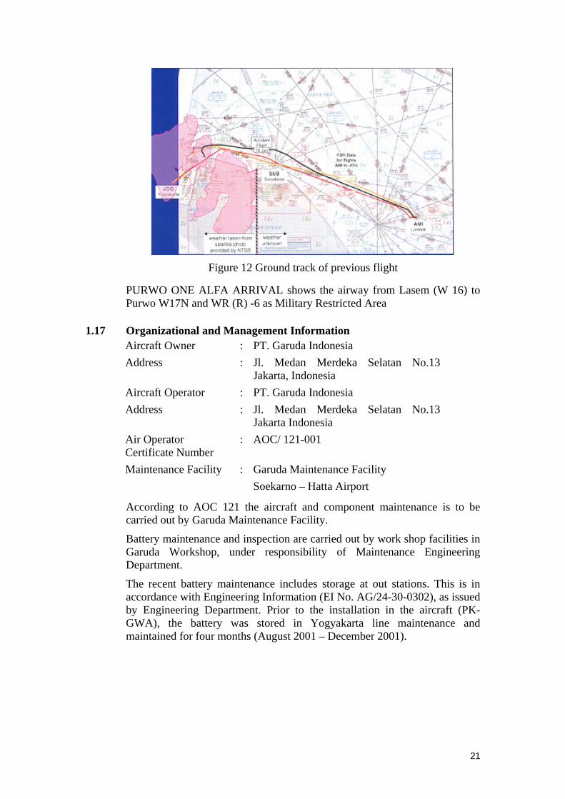
Figure 12 Ground track of previous flight
PURWO ONE ALFA ARRIVAL shows the airway from Lasem (W 16) to Purwo W17N and WR (R) -6 as Military Restricted Area
1.17 Organizational and Management Information Aircraft Owner : PT. Garuda Indonesia Address : Jl. Medan Merdeka Selatan No.13
Jakarta, Indonesia Aircraft Operator : PT. Garuda Indonesia Address : Jl. Medan Merdeka Selatan No.13
Jakarta Indonesia Air Operator Certificate Number
: AOC/ 121-001
Maintenance Facility : Garuda Maintenance Facility Soekarno – Hatta Airport
According to AOC 121 the aircraft and component maintenance is to be carried out by Garuda Maintenance Facility.
Battery maintenance and inspection are carried out by work shop facilities in Garuda Workshop, under responsibility of Maintenance Engineering Department.
The recent battery maintenance includes storage at out stations. This is in accordance with Engineering Information (EI No. AG/24-30-0302), as issued by Engineering Department. Prior to the installation in the aircraft (PK-GWA), the battery was stored in Yogyakarta line maintenance and maintained for four months (August 2001 – December 2001).
21

Figure 13 Garuda Indonesia Airline Organization Chart
1.18 Other Information
1.18.1 Previous CFM56 weather induced flame out Previous cases of accident/incident involving weather induced flame out on B737 on CFM56 engines are as follows. Air Europe in 1987 (dual engine); TACA in 1988 (dual engine); and Continental in 1989 (single engine). All three cases happened during the descending phase (low idle power) and the aircraft were trying to dodge adverse weather condition indicated by red color on the weather radar.
At the time of the hail encounter, all three aircraft were flying in the vicinity of thunderstorms, but were in an area shown as green on the weather radar. These previous events caused the hail capability of the CFM56-3 to be studied and for modification to be made to increase capability in hail. Since the hail modification did not yet exist, all three of these events occurred with an engine configuration that was less tolerant of hail as compared to the engines on PK-GWA.
1.18.2 CFM56-3 Water & Hail Capabilities The modified CFM56-3 engine, as installed in PK-GWA, is presumed to have excess capability of taking in liquid water content at 18,000 ft and flight idle setting (airspeed of 280 KIAS). The MIL-STD-210C stated that at altitude the exposure to 20 g/m3 liquid water content from the rainfall is 1 minute at the probability of 10-8. This type engine has been tested at 12,000 ft and at flight idle (280 KIAS) and did not flame out from exposure to 80 gr/m3 of liquid water content.
22

23
The modified engine has been tested for hail for the equivalence of 280 KIAS at 15,000 ft altitude for 30 seconds of exposure. The flame out limit is 17.8 g/m3 for 32% N1 (flight idle). The maximum hail as defined by the current FAA requirement is 10 g/m3 from 10,000 to 15,000 ft altitude.
The modifications carried out after the TACA 1987 accident are: cutback splitter for water and hail, elliptical spinner for optimum hail deflection, and VBV doors for water and hail, as well as the VBV schedule (full open except in full take off setting).

24

25
2 ANALYSIS 2.1 Encounter with Weather
The focus of the weather data is between 09.00 UTC to 09.20 UTC.
The pilot requested avoiding the weather [before SBY] by changing heading to 300° (intended track for deviating to the North or right of the normal track direct to LASEM) then was instructed to direct “BA” (BLORA) NDB after clearing of the weather.
Crew interview disclosed that there were two openings shown on their weather radar. The PiC decided to take the left opening, while the FO prefer the right opening and discussed it with the PiC.
The NOAA weather satellite image 14 minutes prior to the accident indicated that there was a super cell of Cumulonimbus clouds (see Figure 2), that may have topped out as high as 63,000 ft. The NTSB meteorology experts believe that such cells would feed-up each other and that it is possible for most probable adverse weather condition.
The weather radar senses the density of precipitation by reading electro-magnetic (EM) reflectivity. With the same number of gram of water/m3 of air, hail would have less reflectivity than water vapor. There was also a possibility that the weather radar showed attenuation (shadow) due to precipitation that was so thick with the result that the reflection of the radar EM wave cannot get through. Therefore, the radar display showed gaps, but after entering the precipitation, they became red. It is possible that the crew, based on their training and experience, could not identify such attenuation.
Radar tilt was found at zero. However, this can not be used as evidence of what was being actually displayed during their flight. There is a possibility with a tilt angle of zero the radar may display ground clutter. Crew interviews, however, indicate that the crew may not have intended to perform such tilt in order to see ground.
It is to be noted that weather radar interpretation training was not formally given (but as a hands-on training). Had the crew manipulated the radar tilt to sweep the ground during decent they would have identified the severity of the chosen flight path.
Attenuation induced by either range or intervening precipitation also affects the target displayed or not displayed on the indicator. It should be remembered that as the tilt control is used to sweep a storm target, the cell may change in color, not due to a change in precipitation rate, but in the type of precipitation target encountered.
The most important things, is that the targets displayed on the weather radar indicator are not large enough or intense enough to provide a process-able return signal. Return signals from targets beyond a large storm cell are attenuated, and the displayed target does not accurately represent the real storm cell. It also suggested from CVR read-out analysis that the intensity of attenuation was heard as a GPWS warning “terrain – terrain”.

26
2.2 Engines Flame Out There are five possible reasons for engine flame-out: environment, engine capability, operating procedure, fuel, and commanded shutdown. Fuel has been ruled out from the cause of flame-out since engines examination show that fuel found before engine fuel nozzles indicating the fuel delivery was proper and fuel samples from fuel filter has been tested, in which the result meet the quality standard. Commanded shutdown has also been ruled out from the cause since the comparison of the DFDR data and the engine transient model by CFM International yield that the DFDR data did not match the commanded shutdown model or other DFDR data from CFM56-3 commanded shutdown cases. Operating procedures, such as excessive load to the engine has also been ruled out since it was not supported by DFDR data or pilot interview. Therefore there are two possibilities left, those are environment and engine capability.
2.2.1 Engine capability It was found that the engine has the capability mentioned in 1.18.2. The engines have been certified accordingly and the engine maintenance records and pilot reports did not show any significant anomaly. DFDR data show that the turbine engines performance decrease normally due to aging, as indicated by the increased fuel flow and EGT. The fact that the flame-out of both engines happened at the same time also supports that the engine capability reduction was not due to maintenance since the left and right engine has different ages.
Engine teardown concluded that no abnormal conditions were found in the engine controlling system or engine hardware that could attribute to engine flameout or relight capability. This was supported by DFDR data that the adjustment of fuel flow (topping schedule) indicates good response of the engine controls.
The benchmark for the descent characteristics of the PK-GWA engine fuel flow was taken from the last three flights. The comparison result with the accident flight showed the fuel flow hike was influenced by the water/hail ingestion. The maximum fuel hike (150 lbs/h) was fitted with the cycle model and yielded fuel flow just prior to flame out of about 150 lbs/h which is lower than the topping schedule. The error was in the margin considering the filtering from the data acquisition system and the sampling rate and delay on the recording system. Therefore, from the analysis at that moment, it is unlikely the engine capability contributed to the flame out.
Boeing 737 operation manual for one engine flame out contains engine relight envelope, in which aircraft speed and altitude are the parameters to be considered. The manual for dual engines in-flight restart, however, does not contain such envelope. At the time of the accident, the pilot non flying was reading the emergency checklist, since there is no reference on that particular emergency checklist for the pilot to check, therefore the crew was not aware of airspeed requirement for windmill start during the relight attempt.

27
2.2.2 Environment Environment, in this case the presence of hail, exceeding the certification standard, was the most probable cause since according to flight crews’ interview, the aircraft encountered severe weather at the time. The modified engine is known to have a large water ingestion limit and has been proven to withstand hail concentrations in excess of the required certification standard. Presence of hail, however, still becomes a threat to the engine if the hail density is in excess of the required hail certification standard.
Boeing concluded from the radome condition (see chapter 1.16.5) and engine spool down phenomena, that the aircraft encountered hail, not just rain. This is supported by comparison of the damage of the radome of the aircraft of similar accident (TACA B737-300 24 May 1988).
The flight path on the radar track showed that the flight path was normal and stable, meaning that the aircraft was still in normal condition, until 09.20 UTC when the flight path suddenly made turns southwest bound. Therefore, around 09.20 UTC was the time when both engines might flame out. Radar data also implied that around 09.24 UTC (09.20 UTC DFDR time, ten seconds after both engines flamed out) the aircraft electrical current was out since at that time the SSR (Secondary Surveillance Radar) target faded out.
The engine model showed that the estimated 150 lbs/h fuel hike indicates that a 3.5% water/air ratio existed in the core of the engine, which is equivalent to over 5 g/m3 hail content in the atmosphere. The standard for the highest rain could not result in a 3.5% of water/air ratio. Therefore, hail must have been present in the air at the time. This is supported by the fact that calculated ambient temperature made by Boeing (based on TAT and airspeed) indicated that the temperature at the time the engines flamed out event was about –10° C, which is susceptible for hail to be present.
It is difficult to quantify at an acceptable level of accuracy the quantity of hail and water just from the CVR and DFDR data on the fuel flow, since the fuel hike phenomenon is in the transient level of the system. Therefore, other methods have to be employed to measure the water/hail quantity.
Another method to quantify the density of hail encountered is using the GPWS phenomena. It is recognized from the CVR and DFDR that the radio altimeter picks up high density precipitation as false terrain closure and triggers the GPWS to give terrain warning. It is known that GPWS could give false terrain warning when its radio altimeter signal is reflected by heavy precipitation. However, this method could only be used as an indication of the density of the rain/hail.
The third method to quantify the hail is by using the sound recorded in the cockpit when the aircraft encounter the rain/hail (see Figure 14). Sound energy level reading was synchronized with the DFDR fuel flow data. The data showed positive linear correlation. It is known that the fuel flow is a function of the amount of hail-water ingested by the engine. Therefore, the sound energy level can be correlated with the amount of hail-water ingested. Extrapolation from the CVR sound energy level indicated that the level of hail/water content encountered by PK-GWA at the time of engine flameout could have been as high as 18 grams of hail/m3 of air, depending on the size

and density of the hail/grapple (smaller, more numerous hail/grapple will result in higher water density as compared to larger, fewer hail/grapple).
It could be concluded that damages on the nose radome were caused by external forces, perhaps in the form of hail.
As mentioned above the modified engine has been tested for hail for the equivalence of 280 KIAS at 15,000 ft for 30 seconds of exposure. The water content limit for flame out is 17.8 g/m3 for 32% N1 (flight idle). The maximum hail as defined by, the current FAA requirement is 10 g/m3 from 10,000 – 15,000 ft altitude.
Figure 14 Plot of the recorded sound intensity prior to the engine flame out
From preceding discussions, it can be concluded that the aircraft had encountered hail beyond the engines’ certified capabilities which subsequently caused both engines flame out.
2.3 Restart Failure The crew attempted to relight the engines by following the “Emergency Checklist (ECL): Lost of Thrust on Both Engines Procedure,” which is an initial memory item action, with an unsuccessful result. According to the crew statement taken during their interview, the interval between the first and the second attempt was approximately one minute.
The AOM Page 6.4.17 Loss of Thrust on Both Engines, explains that in moderate or heavy rain it may take up to 3 minutes to accelerate to idle.
Standby AC and DC power failed during the second relight attempt, which was roughly concurrent with an attempt to start the APU.
There are several main causes that could induce failure in engine restart such as the environment, ignition system, start procedure, fuel, and hardware condition.
28

29
Fuel delivery and quality were found not the cause of the failure to relight due to the same reasons as mentioned in engine flame out (see paragraph 2.2).
The followings are highlights on the environment, ignition system, start procedure and hardware condition.
2.3.1 Environment
CFMI engine performance expert mentioned that once flame out occurred; it would be very hard to relight the engine if the aircraft is still in adverse weather. In order to relight the engine after flame-out, one has to bring the condition which enables the engine to sustain itself. Adverse weather and decrease in RPM could induce more water in the engine core. Such attempt to restart would very likely be unsuccessful.
The two restart attempts were most likely carried out while the aircraft was still in precipitation. This condition was beyond the certified engines’ thermodynamic state envelope which is not stated in the Flight Operation Manual.
2.3.2 Re-Start Procedure Comparison of post-event engine conditions from several in-flight engine flame out occurrences (Air Europe, TACA, Continental, Trans Europe Airlines) in relation to anti ice system operation (engine cowl and/or wing) during restart revealed that when the anti ice system was “on” during restart, there were damages on Low Pressure Turbine blades due to high temperature (TACA and Continental). These damages were not found on other accidents (Air Europe and TEA) in which the engine cowl and wing anti ice were “off” (see Appendix A. Table of in-flight engine flame out occurrences due to heavy rain/hail). From this argument, it is recommended to consider that the procedure for in-flight engine restart includes switching off engine cowl and wing anti ice system prior to shifting the engine start lever to IDLE detent.
In this accident aircraft (GWA), it was found that the LP turbine blades were not damaged, it was also found that engine anti ice switches were in OFF position.
2.3.3 Ignition System As for the ignition system, the igniter was tested, in which they still could produce spark even with DC input less than 18 Volt.
An interview with the pilot revealed that the battery was at 22 volt when restart initiated. This fact was used to develop a battery test. The test revealed that the battery will run out of power before the APU start sequence could be completed, if it indicates less than 22 Volt at the beginning of the procedure.
From wreckage examination, it was found that the APU inlet door and the APU fuel shut-off valve were still in closed position. This indicated that the APU start process failed at the initial stage. The damage observed during the teardown and inspection was consistent with an APU that was not operating at the time of impact. The parts examined and/or testing concluded that the inability to achieve an air start of the APU was not due to the APU hardware

30
(see Reference 5). It was concluded that the battery was already run out of power at the initial stage of APU start.
Following this event, the ignition system may also fail because the electrical power remaining was insufficient.
The failure to restart engines was similar to the case of dual engine flame out due to hail, i.e., previous accident (TACA). In this case, even with the available APU power, which means with two igniters at each engine activated, the engines could not be restarted successfully. However, the situation is not comparable with the TACA accident.
2.3.4 Hardware Condition The engines tear down at GE facility shows there is no evidence related to the engine restart failure.
2.4 Battery One of the cells of the battery had been found to have lower electrolyte level to the point causing an insufficient current storage. It caused a high resistance and resulted the voltage of the battery dropped, and will therefore account for the reported failure of the battery. The loss of the battery liquid was due to spewing effect (i.e. convective movement of electrolyte out of the cell).
The spewing was caused by high temperature and overcharging. The reason why the high temperature and overcharging could occur was the absence of high temperature sensor on the battery which functions is to stop charging when the battery temperature is too high. The detachment of the temperature sensor was due to corrosion of the sensor mounting.
The trickle charging procedure as performed during storage will force the battery to consume water. A maintenance item of a Ni-Cad battery is to insure that the water levels meet the specifications in the CMM. Whereas, in the EI AG/24-30-0302, checking the water level is not mentioned. Such practice could result to premature battery failure.
2.5 Weather Avoidance Within Confined Airspace Pilot interview noted that: PiC had decided to turn left considering that an area between two formation of clouds displayed on radar was the safest area, while on NOAA 12 Infrared Scan time 0907 UTC showing that: further left turn was the clearer weather area.
The measurement (plotted from the Scanned weather chart) from clearer weather area was about 10 till 15 nm wide down way through the south west direction in the military restricted area.

Lasem
Purwo Solo
Figure 15 NOAA cloud coverage inside Military Restricted Area
At 0920:47 was the last point of aircraft recorded by the NOAA-12 radar, while this point was about 5 nm from the area of clearer weather areas, it indicated that: this clearer weather area is inside the Military Restricted Area which can be flown by the civil aircraft in coordination with ATC authorities.
2.6 Weather Penetration Technique using weather radar Since everything connected with tilt management is angular, the pilot must have a fast, simple method for converting degrees to feet. That is as tilt is changed in degree, the beam is displaced up or down in varying number of feet, dependent on distance from the antenna.
Inclining the “swept area“ up and, down or level with tilt, the pilot controls what object are detected in the vertical sense, and which object are over – or under-swept and therefore not detected and displayed on the radar display.
Pilot interview noted that the tilt selection was at zero degree while the aircraft was descending trough FL 230, PiC had decided to turn left assuming that an area between two formation of clouds displayed on radar was the safest area considering that mountain Merapi on his right and Military restricted area on his left. Therefore the last selection of zero degree tilt might not cover the threat target, such as cumulus-nimbus cloud formations with turbulence and heavy rain and hail ahead.
31

32

33
3 CONCLUSIONS 3.1 Finding
a. The Flight Data Recorder, Cockpit Voice Recorder, and engines examination confirmed that both engines flame-out, while the aircraft was passing 18,500 ft and entered severe cumulus-nimbus cloud formations with turbulence and heavy rain and hail, was due to excessive water/hail ingestion on the engines which is beyond the engine certified capabilities.
b. The level of electrolyte in the one of the cells (i.e. no. 12) of the battery had been found lower than others. This lower level cell will caused an insufficient current storage.
c. It was found that the thermostat sensor mounting (at the linkage between cells no 11 to 12) was severely corroded and the sensor was missing. The corrosion happened sometimes before the accident, and was not caused by the submersion in the river. The missing sensor was due to corrosion and not by mechanical impact (sees Figure 7).
d. The engine relight attempts were unsuccessful since they were executed while the aircraft was still encountering heavy precipitation and the combustion chamber was thermodynamically insufficient. The effort was followed by a failed APU start attempt resulting in total electrical power loss in the aircraft, which cause the inability to open the APU door.
e. The APU, electrical components and battery tests confirmed that the complete power loss following the APU start attempt was due to battery inability to maintain sufficient power. It was due to inadequacy in the battery maintenance procedures.
f. It was probable that the flight path of the aircraft during weather de-tour when flying into the gap went toward radar shadow cause by an excessive amount of active weather cells in that area.
g. The clearer area was in side the Military Restricted Area, which could be entered in certain situations by obtaining permission which should be established between the relevant authorities.
h. The flight-crew did successfully force land the aircraft on the river despite experiencing multiple emergency situations; lost of thrust on both engines and complete loss of all electrical including battery.
i. One cabin crew fatally injured on forced landing impact; as a result break-off to the lower structure, including both rear lavatories, which were lost by the river stream.
j. The Local Survival Rescue Team had arrived a couple hours after the aircraft ditched on the water of Bengawan Solo River.
k. Aircraft speed of 290 – 295 knots was above the recommended Turbulence Penetration Airspeed of 280 knots.”

34
3.2 Probable Cause The NTSC determines that the probable causes of the accident were the combination of 1) The aircraft had entered severe hail and rain during weather avoidance which subsequently caused both engines flame out; 2) Two attempts of engine-relight failed because the aircraft was still in the precipitation beyond the engines’ certified capabilities; and 3) During the second attempt relight, the aircraft suffered run-out electrical power.

35
4 RECOMMENDATIONS a. Regulatory body, aircraft and engine manufacturer to provide a target
airspeed in the dual engine restart procedures.
b. Regulatory body and weather radar manufacturer to work on the airborne weather radar system to better identify the level of the adverse weather, particularly the characteristic of the present generation of airborne weather radar.
c. Regulatory body and engine manufacturer to provide procedure on how to improve their engine’s water/hail ingestion capability, if adverse weather can not be avoided (i.e. increasing the throttle setting when entering the weather).
d. The aircraft manufacturer should provide engine cowl and wing anti-ice bleed closing procedure prior to the in-flight engine restart.
e. The aircraft and engine manufacturer should provide procedure for in-flight engine relight in precipitation.
f. BMG to provide SIGMET to airmen to assist their decision in flight when expecting en-route adverse weather.
g. BMG to consider the provision of ground based weather radar.
h. Relevant authorities to emphasize the coordination between civilian and military controllers.
i. Rearrangement of both International and National Procedures of the Air Transportation Safety Regulation should be considered after this accident where limited information was provided (no Early Warning on Adverse Weather of active Cb along the track).
j. Training the crew for better reading of the plane’s radar and other relevant subjects/topics in connection with extreme weather condition for Air Transportation Safety.
k. The coordination and consolidation of the operational ground support (ACC/ATC and Meteorological Offices) should be reviwed for proper management of Air Transportation Safety.

36
REFERENCES
a. Reference 1. GE Aircraft Engines. (2002). Engines Hardware Capability Team Report.
b. Reference 2. Boeing Commercial Airplanes. (February 27, 2003). Equipment Quality Analysis Report. Seattle: Author.
c. Reference 3. EI no. AG/24-30-0302
d. Reference 4. Battery self monitoring form at Yogyakarta
e. Reference 5. Honeywell. (September 19, 2002). Teardown Report Of one Model GTCP85-129 Auxiliary Power Unit Garuda Indonesia Boeing 737-3Q8. Phoenix: Author.

37
Appendix A. Chronology of the flight based on ATC report o 08.32 UTC Departure from RWY 27
o 08.35 UTC Passing 6500 ft in contact with Bali Radar Director and cleared to FL310 direct to “SBY” VOR, but on visual condition the pilot requested to fly direct to ENTAS point.
o 08.39 UTC In Contacted with Bali Center on 120,70 MHz approaching 18.000 feet
o 08.44 UTC Pilot requested fly direct to LASEM point o 08.46 UTC Reported reaching FL310 and Bali advised to report abeam “SBY”
VOR. o 09.00 UTC In contact with Bali West on 123, 90 MHz. Controller identified
the flight on squawking A4630 and by radar position at 27 miles North West of “SBY”.
o 09.02 UTC Pilot requested to alter its heading to 300° for avoiding weather then was instructed to fly direct “BA” NDB after clearing the weather.
o 09.08 UTC GIA-421 was instructed to leave FL310 to FL280 due to traffic on eastbound FL 290, GIA-421 descended earlier before encountering opposite traffic.
o 09.11UTC Reported cruising and maintaining FL280
o 09.12 UTC In contact with Semarang APP and cleared to 9000 ft (the pilot reported estimates “BA”09.16 UTC, PURWO at 09.22 UTC and ETA Jogyakarta 09.33 UTC)
o 09.13 UTC Requested to Bali ACC to leave FL280 then descended to FL190 as cleared by Semarang APP
(Note : FL180 is the lower limit of Bali Upper Control and flights must establish two way communication with Semarang APP before entering Semarang TMA).
o 09.16 UTC Permitted to leave Bali West frequency when passing FL230
o 09.17 UTC Contacted Semarang APP when passing FL225 then was instructed to report over PURWO (Pilot estimates PURWO at 09.22z) (the last contact with Semarang APP).


Appendix B. DFDR PLOTS

40

Appendix C. Table of in-flight engine flame out occurrences due to heavy rain/hail
Description Air Europe TACA Continental TEA Trans Europe Airlines Garuda
Incident Simultaneous dual engine flameout
Simultaneous dual engine flameout
Engine #1 flameout Simultaneous dual engine flameout
Simultaneous dual engine flameout
Crew recognition of engine power loss
Both engine generators drop off bus and active master caution enunciator
Both engine generators drop off bus and active master caution enunciator
Engine #1 instruments and illumination of generator off bus light
Both engine generators drop off bus and active master caution enunciator
Both engine generators drop off bus and active master caution enunciator
Crew action Both engines restart using initiated “quick relight” procedure. Relight attempt initiated at about 35 s after generators trip.
APU bleed starter assist starts successful in relight both engines. No thrust response when throttles advance and EGT over-limit light illuminated
Relight engine with windmill start. Engine operated at approximately idle for remainder of flight due to vibration and higher than average EGT
Both engines relight by them self without any action of the pilot
Both engines failed to relight
Flight conditions Descending through 8900 ft at 289 knots
Descending through 16500 ft at 267 knots
Descending through 17000 ft
Descending through 18400 ft at 280 knots
Weather Radar Image Three red areas ahead of aircraft, course altered to avoid red areas. Aircraft on downwind side of storm at flameout
red areas ahead of aircraft, course altered to avoid red areas
Red areas to right aircraft, course altered to avoid red areas. Aircraft on upwind side of storm at flameout
Airplane was in green zone and end at least 4 mile from any indicated red zone
Red areas ahead of aircraft, course altered to the left to avoid red area. Aircraft experienced very heavy turbulence and very heavy noise on
Weather conditions • Light to moderate turbulence;
• Smooth descend; • TAT + 2OC;
• Light rain and turbulence;
• Encountered hail during descend in
• Very heavy turbulence;
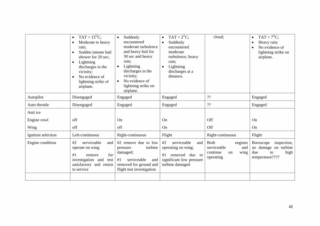
• TAT + 15OC; • Moderate to heavy
rain; • Sudden intense hail
shower for 20 sec; • Lightning
discharges in the vicinity;
• No evidence of lightning strike of airplane.
• Suddenly encountered moderate turbulence and heavy hail for 30 sec and heavy rain;
• Lightning discharges in the vicinity;
• No evidence of lightning strike on airplane.
• TAT + 2OC; • Suddenly
encountered moderate turbulence, heavy rain;
• Lightning discharges at a distance.
cloud;
• TAT + 7OC; • Heavy rain; • No evidence of
lightning strike on airplane.
Autopilot Disengaged Engaged Engaged ?? Engaged
Auto throttle Disengaged Engaged Engaged ?? Engaged
Anti ice
Engine cowl
Wing
off
off
On
off
On
On
Off
Off
On
On
Ignition selection Left-continuous Right-continuous Flight Right-continuous Flight
Engine condition #2 serviceable and operate on wing
#1 remove for investigation and test satisfactory and return to service
#2 remove due to low pressure turbine damaged;
#1 serviceable and removed for ground and flight test investigation
#2 serviceable and operating on wing;
#1 removed due to significant low pressure turbine damaged
Both engines serviceable and continue on wing operating
Boroscope inspection, no damage on turbine due to high temperature????
42