PIC18F14K50: MSSP-SPI
63
Omar Gurrola Microcontrolador PIC18F14K50: MSSP-SPI http://www.proprojects.wordpress.com Revisión: 1.0 [05/2014] CONTENIDO 1. Master Synchronous Serial Port (MSSP) Module ..........................................................................1 2. Serial Peripherial Interface (SPI) ..................................................................................................2 2.1. Comunicación uC a uC................................................................................................................... 3 2.2. Comunicación Con Memoria Winbond W25Q16CVS1G ............................................................... 8 2.3. Comunicación Con Memoria Winbond W25Q32BV ................................................................... 16 2.4. Trabajando Con Transceivers nRF24L01+ 2.4GHz ...................................................................... 20 2.4.1. Comunicación Sin Enhanced Shockburst ................................................................................ 22 2.4.2. Comunicación Con Enhanced Shockburst ............................................................................... 28 2.4.3. Pruebas de Distancia ............................................................................................................... 33 2.5. Utilizando El Convertidor Digital Analogo TLC5615 .................................................................... 47 2.6. Utilizando El Convertidor Digital Analogo TLC5620 .................................................................... 52 2.7. Trabajando Con Una Tarjeta SD En Modo Raw........................................................................... 57 3. Referencias .............................................................................................................................. 61
-
Upload
dragoon-micromar -
Category
Documents
-
view
254 -
download
0
description
Explicación de cómo utilizar el MSSP del PIC18F14K50 con el protocolo SPI y algunos ejemplos como: Memorias Winbond W25QXX, nRF24L01+ 2.4GHz, DAC TLC56XX y SD en modo RAW.
Transcript of PIC18F14K50: MSSP-SPI

Omar Gurrola
Microcontrolador PIC18F14K50: MSSP-SPI http://www.proprojects.wordpress.com
Revisión: 1.0 [05/2014]
CONTENIDO
1. Master Synchronous Serial Port (MSSP) Module ..........................................................................1
2. Serial Peripherial Interface (SPI) ..................................................................................................2
2.1. Comunicación uC a uC................................................................................................................... 3
2.2. Comunicación Con Memoria Winbond W25Q16CVS1G ............................................................... 8
2.3. Comunicación Con Memoria Winbond W25Q32BV ................................................................... 16
2.4. Trabajando Con Transceivers nRF24L01+ 2.4GHz ...................................................................... 20
2.4.1. Comunicación Sin Enhanced Shockburst ................................................................................ 22
2.4.2. Comunicación Con Enhanced Shockburst ............................................................................... 28
2.4.3. Pruebas de Distancia ............................................................................................................... 33
2.5. Utilizando El Convertidor Digital Analogo TLC5615 .................................................................... 47
2.6. Utilizando El Convertidor Digital Analogo TLC5620 .................................................................... 52
2.7. Trabajando Con Una Tarjeta SD En Modo Raw........................................................................... 57
3. Referencias .............................................................................................................................. 61

Omar Gurrola
Microcontrolador PIC18F14K50: MSSP-SPI http://www.proprojects.wordpress.com
Revisión: 1.0 [05/2014] 1
1. Master Synchronous Serial Port (MSSP) Module
Este modulo es una interfaz serial que se utiliza para comunicarse con otros dispositivos (microcontroladores,
memorias, registros de desplazamiento, convertidores A/D, etc). Este modulo puede trabajar con los siguientes
protocolos de comunicación:
SPI (Serial Peripheral Interface)
I2C (Inter Integrated Circuits)
o Modo maestro
o Multi maestro
o Modo esclavo (llamada con dirección general)
Omar Gurrola
Microcontrolador PIC18F14K50: MSSP-SPI http://www.proprojects.wordpress.com
Revisión: 1.0 [05/2014] 2
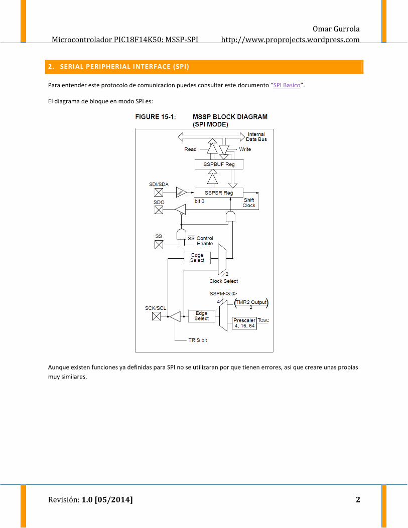
2. SERIAL PERIPHERIAL INTERFACE (SPI)
Para entender este protocolo de comunicacion puedes consultar este documento “SPI Basico”.
El diagrama de bloque en modo SPI es:
Aunque existen funciones ya definidas para SPI no se utilizaran por que tienen errores, asi que creare unas propias
muy similares.

Omar Gurrola
Microcontrolador PIC18F14K50: MSSP-SPI http://www.proprojects.wordpress.com
Revisión: 1.0 [05/2014] 3
2.1. Comunicación uC a uC
En este ejemplo realizaremos un loop back utilizando el protocolo SPI y dos uC, uno configurado como maestro y el otro como esclavo.
El objetivo consiste en que el uC maestro mandara un texto el cual debe recibir el esclavo y regresarlo nuevamente al maestro, cualquier texto que reciba el maestro será transferido por RS-232 a la PC para visualizarlo. Suena sencillo pero veremos que tanto lo es realmente en la práctica.
Si se configura como esclavo no se debe utilizar el modo 00 ya que no sacara datos, no se si se trate de un bug,
pero en la hoja de datos no se comenta nada al respecto, asi que utilizaremos el modo 01 en su lugar.
main.c (MASTER)
/* * Copyright (c) 2011-2013, http://www.proprojects.wordpress.com * All rights reserved. * * Redistribution and use in source and binary forms, with or without modification, * are permitted provided that the following conditions are met: * * 1.- Redistributions of source code must retain the above copyright notice, * this list of conditions and the following disclaimer. * 2.- Redistributions in binary form must reproduce the above copyright notice, * this list of conditions and the following disclaimer in the documentation * and/or other materials provided with the distribution. * * THIS SOFTWARE IS PROVIDED BY THE COPYRIGHT HOLDERS AND CONTRIBUTORS "AS IS" AND ANY * EXPRESS OR IMPLIED WARRANTIES, INCLUDING, BUT NOT LIMITED TO, THE IMPLIED WARRANTIES * OF MERCHANTABILITY AND FITNESS FOR A PARTICULAR PURPOSE ARE DISCLAIMED. * IN NO EVENT SHALL THE COPYRIGHT HOLDER OR CONTRIBUTORS BE LIABLE FOR ANY DIRECT, * INDIRECT, INCIDENTAL, SPECIAL, EXEMPLARY, OR CONSEQUENTIAL DAMAGES (INCLUDING, BUT NOT * LIMITED TO, PROCUREMENT OF SUBSTITUTE GOODS OR SERVICES; LOSS OF USE, DATA, OR PROFITS; * OR BUSINESS INTERRUPTION) HOWEVER CAUSED AND ON ANY THEORY OF LIABILITY, WHETHER IN * CONTRACT, STRICT LIABILITY, OR TORT (INCLUDING NEGLIGENCE OR OTHERWISE) ARISING IN ANY * WAY OUT OF THE USE OF THIS SOFTWARE, EVEN IF ADVISED OF THE POSSIBILITY OF SUCH DAMAGE. */ /********************************************************************************** * Author: Omar Gurrola * Site: http://www.proprojects.wordpress.com * Processor: PIC18 * Compiler: C18 v3.46 * File Name: main.c * Description: Main program * ~~~~~~~~~~~~~~~~~~~~~~~~~~~~~~~~~~~~~~~~~~~~~~~~~~~~~~~~~~~~~~~~~~~~~~~~~~~~~~~~ * Rev. Date Comment * 1.0 06/09/13 Initial version *********************************************************************************/ /** INCLUDES *******************************************************/

Omar Gurrola
Microcontrolador PIC18F14K50: MSSP-SPI http://www.proprojects.wordpress.com
Revisión: 1.0 [05/2014] 4
#include <p18f14k50.h> #include "pic18f14k50_cbits.h" #include "pic18f14k50_io.h" #include "stdvars.h" #include "wait.h" #include "pic18f14k50_spi.h" #include <usart.h> #include <stdio.h> /** DECLARATIONS ***************************************************/ /** VARIABLES ******************************************************/ s8 String[40]; s8 StringOriginal[] = "Hello World TX/RX with SPI Protocol!!"; /** PROTOTYPES *****************************************************/ void HighPriorityISR(void); void LowPriorityISR(void); /** Interrupt Service Routines (ISR)********************************/ #pragma code HP_ISR=0x0008 void HighInterruptVector(void){ _asm goto HighPriorityISR _endasm } #pragma code LP_ISR=0x0018 void LowInterruptVector(void){ _asm goto LowPriorityISR _endasm } #pragma code // Forces the code below this line to be put into the code section #pragma interrupt HighPriorityISR void HighPriorityISR(void){ //Check which interrupt flag caused the interrupt. //Service the interrupt //Clear the interrupt flag //Etc. } //This return will be a "retfie fast", since this is in a #pragma interrupt section #pragma interruptlow LowPriorityISR void LowPriorityISR(void){ //Check which interrupt flag caused the interrupt. //Service the interrupt //Clear the interrupt flag //Etc. } //This return will be a "retfie", since this is in a #pragma interruptlow section void main(void){ SetIntClockTo32MHz(); // EUSART Config baudUSART( BAUD_IDLE_CLK_LOW & // High on idle BAUD_16_BIT_RATE & // 16b BAUD_WAKEUP_OFF & // Disable auto-wake-up BAUD_AUTO_OFF // Disable auto-baud-rate ); OpenUSART( USART_TX_INT_OFF & // Tx Int off USART_RX_INT_OFF & // Rx Int off USART_ASYNCH_MODE & // Asynchronous USART_EIGHT_BIT & // 8bit USART_CONT_RX & // Cont USART_BRGH_HIGH, // High baud rate 832 // for 9,600 bps ); SPIOpen( MTR_FOSC_4, // Master clock = Fosc/4 MODE_01, // Mode SMPMID // Sample at middle of data out ); OpenInRB5(); // RX OpenOutRB7(); // TX while(true){ Waitmsx(250); // Send String by SPI SPISendString(StringOriginal);

Omar Gurrola
Microcontrolador PIC18F14K50: MSSP-SPI http://www.proprojects.wordpress.com
Revisión: 1.0 [05/2014] 5
Waitmsx(250); //Receive string by SPI SPIReadString(String); //Send received string to RS-232 printf("%s\n\r",String); } }
main.c (SLAVE)
/* * Copyright (c) 2011-2013, http://www.proprojects.wordpress.com * All rights reserved. * * Redistribution and use in source and binary forms, with or without modification, * are permitted provided that the following conditions are met: * * 1.- Redistributions of source code must retain the above copyright notice, * this list of conditions and the following disclaimer. * 2.- Redistributions in binary form must reproduce the above copyright notice, * this list of conditions and the following disclaimer in the documentation * and/or other materials provided with the distribution. * * THIS SOFTWARE IS PROVIDED BY THE COPYRIGHT HOLDERS AND CONTRIBUTORS "AS IS" AND ANY * EXPRESS OR IMPLIED WARRANTIES, INCLUDING, BUT NOT LIMITED TO, THE IMPLIED WARRANTIES * OF MERCHANTABILITY AND FITNESS FOR A PARTICULAR PURPOSE ARE DISCLAIMED. * IN NO EVENT SHALL THE COPYRIGHT HOLDER OR CONTRIBUTORS BE LIABLE FOR ANY DIRECT, * INDIRECT, INCIDENTAL, SPECIAL, EXEMPLARY, OR CONSEQUENTIAL DAMAGES (INCLUDING, BUT NOT * LIMITED TO, PROCUREMENT OF SUBSTITUTE GOODS OR SERVICES; LOSS OF USE, DATA, OR PROFITS; * OR BUSINESS INTERRUPTION) HOWEVER CAUSED AND ON ANY THEORY OF LIABILITY, WHETHER IN * CONTRACT, STRICT LIABILITY, OR TORT (INCLUDING NEGLIGENCE OR OTHERWISE) ARISING IN ANY * WAY OUT OF THE USE OF THIS SOFTWARE, EVEN IF ADVISED OF THE POSSIBILITY OF SUCH DAMAGE. */ /********************************************************************************** * Author: Omar Gurrola * Site: http://www.proprojects.wordpress.com * Processor: PIC18 * Compiler: C18 v3.46 * File Name: main.c * Description: Main program * ~~~~~~~~~~~~~~~~~~~~~~~~~~~~~~~~~~~~~~~~~~~~~~~~~~~~~~~~~~~~~~~~~~~~~~~~~~~~~~~~ * Rev. Date Comment * 1.0 06/09/13 Initial version *********************************************************************************/ /** INCLUDES *******************************************************/ #include <p18f14k50.h> #include "pic18f14k50_cbits.h" #include "pic18f14k50_io.h" #include "stdvars.h" #include "wait.h" #include "pic18f14k50_spi.h" /** DECLARATIONS ***************************************************/ /** VARIABLES ******************************************************/ s8 String[40]; /** PROTOTYPES *****************************************************/ void HighPriorityISR(void); void LowPriorityISR(void); /** Interrupt Service Routines (ISR)********************************/ #pragma code HP_ISR=0x0008 void HighInterruptVector(void){ _asm goto HighPriorityISR _endasm } #pragma code LP_ISR=0x0018 void LowInterruptVector(void){ _asm goto LowPriorityISR

Omar Gurrola
Microcontrolador PIC18F14K50: MSSP-SPI http://www.proprojects.wordpress.com
Revisión: 1.0 [05/2014] 6
Diagrama Esquematico:
_endasm } #pragma code // Forces the code below this line to be put into the code section #pragma interrupt HighPriorityISR void HighPriorityISR(void){ //Check which interrupt flag caused the interrupt. //Service the interrupt //Clear the interrupt flag //Etc. } //This return will be a "retfie fast", since this is in a #pragma interrupt section #pragma interruptlow LowPriorityISR void LowPriorityISR(void){ //Check which interrupt flag caused the interrupt. //Service the interrupt //Clear the interrupt flag //Etc. } //This return will be a "retfie", since this is in a #pragma interruptlow section void main(void){ SetIntClockTo32MHz(); SPIOpen( SLV_SSON, // Slave SS on MODE_01, // Mode SMPMID // Sample at middle of data out ); while(true){ //Receive string by SPI SPIReadString(String); //Send string by SPI SPISendString(String); } }

Omar Gurrola
Microcontrolador PIC18F14K50: MSSP-SPI http://www.proprojects.wordpress.com
Revisión: 1.0 [05/2014] 7
Circuito Armado:

Omar Gurrola
Microcontrolador PIC18F14K50: MSSP-SPI http://www.proprojects.wordpress.com
Revisión: 1.0 [05/2014] 8
2.2. Comunicación Con Memoria Winbond W25Q16CVS1G
En este ejemplo vamos a diseñar un driver para leer y escribir en una memoria W25Q16CVS1G de la empresa Winbond, por medio de SPI.
Las características de la memoria son:
Single 2.7 to 3.6v supply.
Standard SPI / Dual SPI / Quad SPI.
104 MHz Standard (Dual x2, Quad x4).
100,000 erase/program cycles and 20-year data retention.
16 M-bit / 2M-byte.
256-byte per page.
4KB sectors.
64-Bit unique ID for each device.
SW and HW write protect.
Los pines son:

Omar Gurrola
Microcontrolador PIC18F14K50: MSSP-SPI http://www.proprojects.wordpress.com
Revisión: 1.0 [05/2014] 9
El diagrama de bloque de la memoria es:
Como la memoria trabaja con 3.3v tendremos que alimentar todo con el mismo voltaje, lo bueno es que el PIC18F14K50 lo soporta.
Debido a que el uC solo dispone de un modulo SPI estándar, trabajaremos la memoria de esa manera, los modos soportados son: Modo 0 (0,0) y 3 (1,1).
En general para trabajar con esta memoria se trabajara con los registos de estados y las instrucciones.
Los registros de estados son utilizados para darnos el estado de la memoria como: escritura habilitada o deshabilitada, opciones de modo quad, el estado de escritura o lectura, protección de ciertas zonas, etc. Los registros de estados son los siguientes:

Omar Gurrola
Microcontrolador PIC18F14K50: MSSP-SPI http://www.proprojects.wordpress.com
Revisión: 1.0 [05/2014] 10
Los unicos bits que nos interesan del Status Register-1 [S0-S7] son BUSY y WEL ya que los demas son para proteger zonas de la memoria que no utilizaremos en este ejemplo.
BUSY [S0-ReadOnly]: bit que se pone en uno cuando el dispositivo ejecuta: Page program, quad page program, sector erase, block erase, chip erase, write status register, erase/program security register. Durante este tiempo el dispositivo ignorada cualquier otra instrucción enviada, excepto leer el registro de estados y la instrucción de detener temporalmente el borrado/programado.
WEL [S1-ReadOnly]: bit que se pone en uno cuando se manda una instrucción de habilitación de escritura y se pone en cero cuando el dipositivo tiene deshabilitada la escritura. Se puede deshablilitar la escritura en: power-up, write disable, page program, quad page program, sector erase, block erase, chip erase, write status register, erase security register y program security register.
Los unicos bits que nos interesan del Status Register-2 [S8-S15] es SUS unicamente.
SUS [S15-ReadOnly]: bit que se pone en uno despues de ejecutar una instrucción de suspension, y se regresa a cero cuando se ejecuta una instrucción de resumen, power-down y power-up.
Las instrucciones que se pueden enviar a esta memoria son 35, cualquier instrucción es enviada después de bajar /SS y son ejecutadas hasta que se ahiga subido /SS.

Omar Gurrola
Microcontrolador PIC18F14K50: MSSP-SPI http://www.proprojects.wordpress.com
Revisión: 1.0 [05/2014] 11

Omar Gurrola
Microcontrolador PIC18F14K50: MSSP-SPI http://www.proprojects.wordpress.com
Revisión: 1.0 [05/2014] 12
main.c
/* * Copyright (c) 2011-2013, http://www.proprojects.wordpress.com * All rights reserved. * * Redistribution and use in source and binary forms, with or without modification, * are permitted provided that the following conditions are met: * * 1.- Redistributions of source code must retain the above copyright notice, * this list of conditions and the following disclaimer. * 2.- Redistributions in binary form must reproduce the above copyright notice, * this list of conditions and the following disclaimer in the documentation * and/or other materials provided with the distribution. * * THIS SOFTWARE IS PROVIDED BY THE COPYRIGHT HOLDERS AND CONTRIBUTORS "AS IS" AND ANY * EXPRESS OR IMPLIED WARRANTIES, INCLUDING, BUT NOT LIMITED TO, THE IMPLIED WARRANTIES * OF MERCHANTABILITY AND FITNESS FOR A PARTICULAR PURPOSE ARE DISCLAIMED. * IN NO EVENT SHALL THE COPYRIGHT HOLDER OR CONTRIBUTORS BE LIABLE FOR ANY DIRECT, * INDIRECT, INCIDENTAL, SPECIAL, EXEMPLARY, OR CONSEQUENTIAL DAMAGES (INCLUDING, BUT NOT * LIMITED TO, PROCUREMENT OF SUBSTITUTE GOODS OR SERVICES; LOSS OF USE, DATA, OR PROFITS; * OR BUSINESS INTERRUPTION) HOWEVER CAUSED AND ON ANY THEORY OF LIABILITY, WHETHER IN * CONTRACT, STRICT LIABILITY, OR TORT (INCLUDING NEGLIGENCE OR OTHERWISE) ARISING IN ANY * WAY OUT OF THE USE OF THIS SOFTWARE, EVEN IF ADVISED OF THE POSSIBILITY OF SUCH DAMAGE. */ /********************************************************************************** * Author: Omar Gurrola * Site: http://www.proprojects.wordpress.com * Processor: PIC18 * Compiler: C18 v3.46 * File Name: main.c * Description: Main program * ~~~~~~~~~~~~~~~~~~~~~~~~~~~~~~~~~~~~~~~~~~~~~~~~~~~~~~~~~~~~~~~~~~~~~~~~~~~~~~~~ * Rev. Date Comment * 1.0 06/11/13 Initial version *********************************************************************************/ /** INCLUDES *******************************************************/ #include <p18f14k50.h> #include "pic18f14k50_cbits.h" #include "pic18f14k50_io.h" #include "stdvars.h" #include "wait.h" #include <usart.h> #include <stdio.h> #include "w25q16.h" /** DECLARATIONS ***************************************************/ /** VARIABLES ******************************************************/ /** PROTOTYPES *****************************************************/ void HighPriorityISR(void); void LowPriorityISR(void); /** Interrupt Service Routines (ISR)********************************/ #pragma code HP_ISR=0x0008 void HighInterruptVector(void){ _asm goto HighPriorityISR _endasm } #pragma code LP_ISR=0x0018 void LowInterruptVector(void){ _asm goto LowPriorityISR _endasm } #pragma code // Forces the code below this line to be put into the code section #pragma interrupt HighPriorityISR void HighPriorityISR(void){ //Check which interrupt flag caused the interrupt. //Service the interrupt //Clear the interrupt flag //Etc. } //This return will be a "retfie fast", since this is in a #pragma interrupt section

Omar Gurrola
Microcontrolador PIC18F14K50: MSSP-SPI http://www.proprojects.wordpress.com
Revisión: 1.0 [05/2014] 13
#pragma interruptlow LowPriorityISR void LowPriorityISR(void){ //Check which interrupt flag caused the interrupt. //Service the interrupt //Clear the interrupt flag //Etc. } //This return will be a "retfie", since this is in a #pragma interruptlow section void main(void){ SetIntClockTo32MHz(); // EUSART Config baudUSART( BAUD_IDLE_CLK_LOW & // High on idle BAUD_16_BIT_RATE & // 16b BAUD_WAKEUP_OFF & // Disable auto-wake-up BAUD_AUTO_OFF // Disable auto-baud-rate ); OpenUSART( USART_TX_INT_OFF & // Tx Int off USART_RX_INT_OFF & // Rx Int off USART_ASYNCH_MODE & // Asynchronous USART_EIGHT_BIT & // 8bit USART_CONT_RX & // Cont USART_BRGH_HIGH, // High baud rate 832 // 832 for 9,600 bps ); OpenInRB5(); // RX OpenOutRB7(); // TX w25q16_spi_open( MTR_FOSC_4, // Fosc/4 MODE_00, // Mode SMPMID // Middle ); while(true){ u24 jid; u16 id; u8 uniqueid[4]; u8 st1,st2; u16 t; u8 buffer[16]; jid = w25q16_read_jedecid(); id = w25q16_read_mandevid(); w25q16_read_uniqueid64(&uniqueid[0]); st1 = w25q16_read_statusregx(STATUS_REGISTER1); st2 = w25q16_read_statusregx(STATUS_REGISTER2); printf("JID: %.6HX\n\r",jid); printf("ID: %.4hX\n\r",id); printf("UniqueID: "); for(t = 0; t < 8; t++) { printf("%.2X",uniqueid[t]); } printf("\n\r"); printf("STATUS1: %.8B\n\r", st1); printf("STATUS2: %.8B\n\r", st2); printf("------------------------------------------\n\r"); printf("Reading first 256B:\n\r"); w25q16_cont_read_init(FAST_READ,0x000000); for(t = 0; t < 256; t++) { WriteUSART(w25q16_cont_read()); while(BusyUSART()); } w25q16_init_stop(); printf("\n\r------------------------------------------\n\r"); printf("Erasing first 4KB:\n\r"); w25q16_erase(SECTOR_4KB,0x000000); printf("Reading erased first 256B:\n\r"); w25q16_cont_read_init(FAST_READ,0x000000); for(t = 0; t < 256; t++) { WriteUSART(w25q16_cont_read()); while(BusyUSART()); } w25q16_init_stop(); printf("\n\r------------------------------------------\n\r");

Omar Gurrola
Microcontrolador PIC18F14K50: MSSP-SPI http://www.proprojects.wordpress.com
Revisión: 1.0 [05/2014] 14
Diagrama Esquematico:
printf("Writing first 256B:\n\r"); w25q16_page_program_init(0x000000); for(t = 0; t < 256; t++) { w25q16_page_program_write('X'); } w25q16_init_stop(); printf("------------------------------------------\n\r"); printf("Reading again first 256B:\n\r"); w25q16_cont_read_init(FAST_READ,0x000000); for(t = 0; t < 256; t++) { WriteUSART(w25q16_cont_read()); while(BusyUSART()); } w25q16_init_stop(); printf("\n\r------------------------------------------\n\r"); while(true); } }

Omar Gurrola
Microcontrolador PIC18F14K50: MSSP-SPI http://www.proprojects.wordpress.com
Revisión: 1.0 [05/2014] 15
Circuito Armado:

Omar Gurrola
Microcontrolador PIC18F14K50: MSSP-SPI http://www.proprojects.wordpress.com
Revisión: 1.0 [05/2014] 16
2.3. Comunicación Con Memoria Winbond W25Q32BV
Esta memoria tiene la misma arquitectura que la memoria W25Q16CV, asi que las instrucciones utilizadas en el ejemplo anterior tambien funcionan con esta, la única diferencia es que tiene el doble de memoria (32Mb o 4MB), es decir las direcciones van desde 0x000000 hasta 0x3FFFFF.
En este ejemplo leeremos los identificadores de la memoria y escribiremos una cadena de texto al inicio y final de la memoria y mostraremos que el fue escrito.
main.c
/* * Copyright (c) 2011-2013, http://www.proprojects.wordpress.com * All rights reserved. * * Redistribution and use in source and binary forms, with or without modification, * are permitted provided that the following conditions are met: * * 1.- Redistributions of source code must retain the above copyright notice, * this list of conditions and the following disclaimer. * 2.- Redistributions in binary form must reproduce the above copyright notice, * this list of conditions and the following disclaimer in the documentation * and/or other materials provided with the distribution. * * THIS SOFTWARE IS PROVIDED BY THE COPYRIGHT HOLDERS AND CONTRIBUTORS "AS IS" AND ANY * EXPRESS OR IMPLIED WARRANTIES, INCLUDING, BUT NOT LIMITED TO, THE IMPLIED WARRANTIES * OF MERCHANTABILITY AND FITNESS FOR A PARTICULAR PURPOSE ARE DISCLAIMED. * IN NO EVENT SHALL THE COPYRIGHT HOLDER OR CONTRIBUTORS BE LIABLE FOR ANY DIRECT, * INDIRECT, INCIDENTAL, SPECIAL, EXEMPLARY, OR CONSEQUENTIAL DAMAGES (INCLUDING, BUT NOT * LIMITED TO, PROCUREMENT OF SUBSTITUTE GOODS OR SERVICES; LOSS OF USE, DATA, OR PROFITS; * OR BUSINESS INTERRUPTION) HOWEVER CAUSED AND ON ANY THEORY OF LIABILITY, WHETHER IN * CONTRACT, STRICT LIABILITY, OR TORT (INCLUDING NEGLIGENCE OR OTHERWISE) ARISING IN ANY * WAY OUT OF THE USE OF THIS SOFTWARE, EVEN IF ADVISED OF THE POSSIBILITY OF SUCH DAMAGE. */ /********************************************************************************** * Author: Omar Gurrola * Site: http://www.proprojects.wordpress.com * Processor: PIC18 * Compiler: C18 v3.46 * File Name: main.c * Description: Main program * ~~~~~~~~~~~~~~~~~~~~~~~~~~~~~~~~~~~~~~~~~~~~~~~~~~~~~~~~~~~~~~~~~~~~~~~~~~~~~~~~ * Rev. Date Comment * 1.0 06/11/13 Initial version *********************************************************************************/ /** INCLUDES *******************************************************/ #include <p18f14k50.h> #include "pic18f14k50_cbits.h" #include "pic18f14k50_io.h" #include "stdvars.h" #include "wait.h" #include <usart.h> #include <stdio.h> #include "w25q32.h" /** DECLARATIONS ***************************************************/ /** VARIABLES ******************************************************/ /** PROTOTYPES *****************************************************/ void HighPriorityISR(void); void LowPriorityISR(void); void read_and_show_data(void); /** Interrupt Service Routines (ISR)********************************/ #pragma code HP_ISR=0x0008 void HighInterruptVector(void){ _asm goto HighPriorityISR _endasm

Omar Gurrola
Microcontrolador PIC18F14K50: MSSP-SPI http://www.proprojects.wordpress.com
Revisión: 1.0 [05/2014] 17
} #pragma code LP_ISR=0x0018 void LowInterruptVector(void){ _asm goto LowPriorityISR _endasm } #pragma code // Forces the code below this line to be put into the code section #pragma interrupt HighPriorityISR void HighPriorityISR(void){ //Check which interrupt flag caused the interrupt. //Service the interrupt //Clear the interrupt flag //Etc. } //This return will be a "retfie fast", since this is in a #pragma interrupt section #pragma interruptlow LowPriorityISR void LowPriorityISR(void){ //Check which interrupt flag caused the interrupt. //Service the interrupt //Clear the interrupt flag //Etc. } //This return will be a "retfie", since this is in a #pragma interruptlow section void main(void){ SetIntClockTo32MHz(); // EUSART Config baudUSART( BAUD_IDLE_CLK_LOW & // High on idle BAUD_16_BIT_RATE & // 16b BAUD_WAKEUP_OFF & // Disable auto-wake-up BAUD_AUTO_OFF // Disable auto-baud-rate ); OpenUSART( USART_TX_INT_OFF & // Tx Int off USART_RX_INT_OFF & // Rx Int off USART_ASYNCH_MODE & // Asynchronous USART_EIGHT_BIT & // 8bit USART_CONT_RX & // Cont USART_BRGH_HIGH, // High baud rate 832 // 832 for 9,600 bps ); OpenInRB5(); // RX OpenOutRB7(); // TX w25q32_spi_open( MTR_FOSC_4, // Fosc/4 MODE_00, // Mode SMPMID // Middle ); while(true){ u8 uniqueid[4]; u8 st1,st2; u16 t; u8 String[] = "Writing to SPI E2PROM Memory!"; w25q32_read_uniqueid64(&uniqueid[0]); st1 = w25q32_read_statusregx(STATUS_REGISTER1); st2 = w25q32_read_statusregx(STATUS_REGISTER2); printf("------------------------------------------\n\r"); printf("JID: %.6HX\n\r",w25q32_read_jedecid()); printf("ID: %.4hX\n\r",w25q32_read_mandevid()); printf("UniqueID: "); for(t = 0; t < 8; t++) { printf("%.2X",uniqueid[t]); } printf("\n\r"); printf("STATUS1: %.8B\n\r", st1); printf("STATUS2: %.8B\n\r", st2); printf("------------------------------------------\n\r"); printf("Erasing all memory...\n\r"); w25q32_erase_all(); read_and_show_data(); printf("Writing text in first 30 bytes of memory...\n\r"); w25q32_writebytes(0x000000,30,&String[0]); printf("Writing text in las 30 bytes of memory...\n\r");

Omar Gurrola
Microcontrolador PIC18F14K50: MSSP-SPI http://www.proprojects.wordpress.com
Revisión: 1.0 [05/2014] 18
Diagrama Esquematico:
w25q32_writebytes(0x3FFFE1,30,&String[0]); read_and_show_data(); printf("Finish..................."); while(true); } } void read_and_show_data(void) { u8 t; printf("Reading first 30 Bytes of memory...\n\r"); w25q32_cont_read_init(NORMAL_READ,0x000000); for(t = 0; t < 30; t++) { printf("%c", w25q32_cont_read()); } w25q32_init_stop(); printf("\n\r"); printf("Reading last 30 Bytes of memory...\n\r"); w25q32_cont_read_init(NORMAL_READ,0x3FFFE1); for(t = 0; t < 30; t++) { printf("%c", w25q32_cont_read()); } w25q32_init_stop(); printf("\n\r"); }

Omar Gurrola
Microcontrolador PIC18F14K50: MSSP-SPI http://www.proprojects.wordpress.com
Revisión: 1.0 [05/2014] 19
Circuito Armado:

Omar Gurrola
Microcontrolador PIC18F14K50: MSSP-SPI http://www.proprojects.wordpress.com
Revisión: 1.0 [05/2014] 20
2.4. Trabajando Con Transceivers nRF24L01+ 2.4GHz
En este ejemplo se trabajara con dos modulos nRF24L01+ para realizar una comunicación inalambrica. Las características de los modulos son:
Compatible con nRF24L01 (Antecesor)
Banda de 2.4 GHz
Transferencia de : o -94dBm RX - 250Kbps o -85dBm RX - 1Mbps o -82dBm RX - 2Mbps
Muy bajo consumo y administración avanzada de energía o 11.3mA pico en TX a 0dB o 13.5mA pico de RX a 2Mbps o 900nA en modo power down
125 canales y multipunto.
Regulador en chip, 1.9v a 3.6v
Pines tolerantes a +5v
Temperatura de -40*C hasta 80*C
Protocolo SPI hasta 10Mbps
Capa de link en hardware (Enhanced ShockBurst) o Ensamble automatic de paquete (Preamble, address and CRC) o Longuitud dinamica de datos (payload) de 1 hasta 32Bytes o posibilidad de seleccionar auto respuesta (acknowledgment) con datos (payload) o Auto retransmisión o 6 pipas de datos (Multiceiver)
El module es el siguiente:

Omar Gurrola
Microcontrolador PIC18F14K50: MSSP-SPI http://www.proprojects.wordpress.com
Revisión: 1.0 [05/2014] 21
El pinout de los modules son:
La librería para trabajar con estos modulos e incluso los ejemplos fuerón brindados por Brennen Ball utilizando sus
tutoriales sobre nRF24L01, pueden consultar estos documentos en la sección de referencias.

Omar Gurrola
Microcontrolador PIC18F14K50: MSSP-SPI http://www.proprojects.wordpress.com
Revisión: 1.0 [05/2014] 22
2.4.1. Comunicación Sin Enhanced Shockburst
En este ejemplo vamos a realizar una comunicación inalámbrica entre dos nrf24l01, cada uno con un uC PIC18F14K50. La computadora en una terminal serial iniciara la comunicación, mandando un carácter al primer uC, el cual transferida este carácter al segundo modulo. Este segundo modulo lo regresara y deberá ser mostrado en la compu nuevamente, si en un tiempo definido no se recibe el carácter mostrara “?”. Para este ejemplo no utilizaremos la capa link.
MASTER: main.c
/* * Copyright (c) 2011-2013, http://www.proprojects.wordpress.com * All rights reserved. * * Redistribution and use in source and binary forms, with or without modification, * are permitted provided that the following conditions are met: * * 1.- Redistributions of source code must retain the above copyright notice, * this list of conditions and the following disclaimer. * 2.- Redistributions in binary form must reproduce the above copyright notice, * this list of conditions and the following disclaimer in the documentation * and/or other materials provided with the distribution. * * THIS SOFTWARE IS PROVIDED BY THE COPYRIGHT HOLDERS AND CONTRIBUTORS "AS IS" AND ANY * EXPRESS OR IMPLIED WARRANTIES, INCLUDING, BUT NOT LIMITED TO, THE IMPLIED WARRANTIES * OF MERCHANTABILITY AND FITNESS FOR A PARTICULAR PURPOSE ARE DISCLAIMED. * IN NO EVENT SHALL THE COPYRIGHT HOLDER OR CONTRIBUTORS BE LIABLE FOR ANY DIRECT, * INDIRECT, INCIDENTAL, SPECIAL, EXEMPLARY, OR CONSEQUENTIAL DAMAGES (INCLUDING, BUT NOT * LIMITED TO, PROCUREMENT OF SUBSTITUTE GOODS OR SERVICES; LOSS OF USE, DATA, OR PROFITS; * OR BUSINESS INTERRUPTION) HOWEVER CAUSED AND ON ANY THEORY OF LIABILITY, WHETHER IN * CONTRACT, STRICT LIABILITY, OR TORT (INCLUDING NEGLIGENCE OR OTHERWISE) ARISING IN ANY * WAY OUT OF THE USE OF THIS SOFTWARE, EVEN IF ADVISED OF THE POSSIBILITY OF SUCH DAMAGE. */ /********************************************************************************** * Author: Omar Gurrola * Site: http://www.proprojects.wordpress.com * Processor: PIC18 * Compiler: C18 v3.46 * File Name: main.c * Description: Main program * ~~~~~~~~~~~~~~~~~~~~~~~~~~~~~~~~~~~~~~~~~~~~~~~~~~~~~~~~~~~~~~~~~~~~~~~~~~~~~~~~ * Rev. Date Comment * 1.0 10/03/13 Initial version *********************************************************************************/ /** INCLUDES *******************************************************/ #include <p18f14k50.h> #include <GenericTypeDefs.h> #include "stdvars.h" #include "pic18f14k50_cbits.h" #include "pic18f14k50_io.h" #include "wait.h" #include <stdio.h> #include <usart.h> #include "spi1.h" #include "nrf24l01.h" /** DECLARATIONS ***************************************************/ //#define _XTAL_FREQ 32000000 // The speed of your internal(or)external oscillator

Omar Gurrola
Microcontrolador PIC18F14K50: MSSP-SPI http://www.proprojects.wordpress.com
Revisión: 1.0 [05/2014] 23
/** VARIABLES ******************************************************/ /** PROTOTYPES *****************************************************/ void Initialize(void); void InitializeIO(void); void ToggleLED(void); /** Interrupt Service Routines (ISR)********************************/ void main(void){ u8 data; u16 count; Initialize(); while(TRUE){ //check UART status register to see if data has been received. if so, process while(DataRdyUSART()) { data = ReadUSART(); //get data from UART //WriteUSART(data); //get data from UART //continue; nrf24l01_write_tx_payload(&data, 1, true); //transmit received char over RF //wait until the packet has been sent or the maximum number of retries has been reached while(!(nrf24l01_irq_pin_active() && nrf24l01_irq_tx_ds_active())); nrf24l01_irq_clear_all(); //clear all interrupts in the 24L01 nrf24l01_set_as_rx(true); //change the device to an RX to get the character back from the other 24L01 //wait a while to see if we get the data back (change the loop maximum and the lower if // argument (should be loop maximum - 1) to lengthen or shorten this time frame for(count = 0; count < 20000; count++) { //check to see if the data has been received. if so, get the data and exit the loop. // if the loop is at its last count, assume the packet has been lost and set the data // to go to the UART to "?". If neither of these is true, keep looping. if((nrf24l01_irq_pin_active() && nrf24l01_irq_rx_dr_active())) { nrf24l01_read_rx_payload(&data, 1); //get the payload into data break; } //if loop is on its last iteration, assume packet has been lost. if(count == 19999) data = '?'; } nrf24l01_irq_clear_all(); //clear interrupts again printf("%c", data); //print the received data (or ? if none) to the screen Wait200us(); //wait for receiver to come from standby to RX 130uS nrf24l01_set_as_tx(); //resume normal operation as a TX ToggleLED(); //toggle the on-board LED as visual indication that the loop has completed } } } // Override putc for printf(); void putc(INT8 data) { while(BusyUSART()); // Check buffer WriteUSART(data); // Send data } void ToggleLED(void) { WriteRC0(!ReadRC0()); } //initialize routine void Initialize(void) {

Omar Gurrola
Microcontrolador PIC18F14K50: MSSP-SPI http://www.proprojects.wordpress.com
Revisión: 1.0 [05/2014] 24
SetIntClockTo32MHz(); InitializeIO(); //set up IO (directions and functions) // USART Config baudUSART( BAUD_IDLE_CLK_LOW & // Idle BAUD_16_BIT_RATE & // 16b BAUD_WAKEUP_OFF & // Disable auto-wake-up BAUD_AUTO_OFF // Disable auto-baud-rate ); OpenUSART( USART_TX_INT_OFF & // Tx Int off USART_RX_INT_OFF & // Rx Int off USART_ASYNCH_MODE & // Asynchronous USART_EIGHT_BIT & // 8bit USART_CONT_RX & // Cont USART_BRGH_HIGH, // High baud rate 832 // for 9,600 bps ); BAUDCONbits.DTRXP = 0; // We need to define polarity of RX, 0 = Low idle (Because a BUG in library) // SPI Config in mode 0 OpenSPI(SPI_FOSC_16, MODE_00, SMPMID); nrf24l01_initialize_debug(false, 1, false); //initialize the 24L01 to the debug configuration as TX, 1 data byte, and auto-ack disabled } //initialize IO pins void InitializeIO(void) { // Config USART pins OpenInRB5(); // RX In OpenOutRB7(); // TX Out // Configure SPI pins OpenOutRC7(); // MOSI out OpenInRB4(); // MISO in OpenOutRB6(); // SCK out OpenOutRC1(); // /CS out WriteRC1(1); // /CS = 1 // Configure nRF pins OpenOutRC2(); // CE out OpenInRC3(); // IRQ in // Led OpenOutRC0(); // LED out WriteRC0(0); // LED off }
LOOPER: main.c
/* * Copyright (c) 2011-2013, http://www.proprojects.wordpress.com * All rights reserved. * * Redistribution and use in source and binary forms, with or without modification, * are permitted provided that the following conditions are met: * * 1.- Redistributions of source code must retain the above copyright notice, * this list of conditions and the following disclaimer. * 2.- Redistributions in binary form must reproduce the above copyright notice, * this list of conditions and the following disclaimer in the documentation * and/or other materials provided with the distribution. * * THIS SOFTWARE IS PROVIDED BY THE COPYRIGHT HOLDERS AND CONTRIBUTORS "AS IS" AND ANY * EXPRESS OR IMPLIED WARRANTIES, INCLUDING, BUT NOT LIMITED TO, THE IMPLIED WARRANTIES * OF MERCHANTABILITY AND FITNESS FOR A PARTICULAR PURPOSE ARE DISCLAIMED. * IN NO EVENT SHALL THE COPYRIGHT HOLDER OR CONTRIBUTORS BE LIABLE FOR ANY DIRECT, * INDIRECT, INCIDENTAL, SPECIAL, EXEMPLARY, OR CONSEQUENTIAL DAMAGES (INCLUDING, BUT NOT * LIMITED TO, PROCUREMENT OF SUBSTITUTE GOODS OR SERVICES; LOSS OF USE, DATA, OR PROFITS; * OR BUSINESS INTERRUPTION) HOWEVER CAUSED AND ON ANY THEORY OF LIABILITY, WHETHER IN * CONTRACT, STRICT LIABILITY, OR TORT (INCLUDING NEGLIGENCE OR OTHERWISE) ARISING IN ANY * WAY OUT OF THE USE OF THIS SOFTWARE, EVEN IF ADVISED OF THE POSSIBILITY OF SUCH DAMAGE.

Omar Gurrola
Microcontrolador PIC18F14K50: MSSP-SPI http://www.proprojects.wordpress.com
Revisión: 1.0 [05/2014] 25
*/ /********************************************************************************** * Author: Omar Gurrola * Site: http://www.proprojects.wordpress.com * Processor: PIC18 * Compiler: C18 v3.46 * File Name: main.c * Description: Main program * ~~~~~~~~~~~~~~~~~~~~~~~~~~~~~~~~~~~~~~~~~~~~~~~~~~~~~~~~~~~~~~~~~~~~~~~~~~~~~~~~ * Rev. Date Comment * 1.0 10/03/13 Initial version *********************************************************************************/ /** INCLUDES *******************************************************/ #include <p18f14k50.h> #include <GenericTypeDefs.h> #include "stdvars.h" #include "pic18f14k50_cbits.h" #include "pic18f14k50_io.h" #include "wait.h" #include <stdio.h> #include <usart.h> #include "spi1.h" #include "nrf24l01.h" /** DECLARATIONS ***************************************************/ //#define _XTAL_FREQ 32000000 // The speed of your internal(or)external oscillator /** VARIABLES ******************************************************/ /** PROTOTYPES *****************************************************/ void Initialize(void); void InitializeIO(void); void ToggleLED(void); /** Interrupt Service Routines (ISR)********************************/ void main(void){ u8 data; Initialize(); while(TRUE){ //wait until a packet has been received while(!(nrf24l01_irq_pin_active() && nrf24l01_irq_rx_dr_active())); nrf24l01_read_rx_payload(&data, 1); //read the packet into data nrf24l01_irq_clear_all(); //clear all interrupts in the 24L01 Wait200us(); //wait for the other 24L01 to come from standby to RX nrf24l01_set_as_tx(); //change the device to a TX to send back from the other 24L01 nrf24l01_write_tx_payload(&data, 1, true); //transmit received char over RF //wait until the packet has been sent while(!(nrf24l01_irq_pin_active() && nrf24l01_irq_tx_ds_active())); nrf24l01_irq_clear_all(); //clear interrupts again nrf24l01_set_as_rx(true); //resume normal operation as an RX ToggleLED(); //toggle the on-board LED as visual indication that the loop has completed } } // Override putc for printf(); void putc(INT8 data) { while(BusyUSART()); // Check buffer WriteUSART(data); // Send data } void ToggleLED(void) { WriteRC0(!ReadRC0()); }

Omar Gurrola
Microcontrolador PIC18F14K50: MSSP-SPI http://www.proprojects.wordpress.com
Revisión: 1.0 [05/2014] 26
//initialize routine void Initialize(void) { SetIntClockTo32MHz(); InitializeIO(); //set up IO (directions and functions) // USART Config baudUSART( BAUD_IDLE_CLK_LOW & // Idle BAUD_16_BIT_RATE & // 16b BAUD_WAKEUP_OFF & // Disable auto-wake-up BAUD_AUTO_OFF // Disable auto-baud-rate ); OpenUSART( USART_TX_INT_OFF & // Tx Int off USART_RX_INT_OFF & // Rx Int off USART_ASYNCH_MODE & // Asynchronous USART_EIGHT_BIT & // 8bit USART_CONT_RX & // Cont USART_BRGH_HIGH, // High baud rate 832 // for 9,600 bps ); BAUDCONbits.DTRXP = 0; // We need to define polarity of RX, 0 = Low idle (Because a BUG in library) // SPI Config in mode 0 OpenSPI(SPI_FOSC_16, MODE_00, SMPMID); nrf24l01_initialize_debug(true, 1, false); //initialize the 24L01 to the debug configuration as TX, 1 data byte, and auto-ack disabled } //initialize IO pins void InitializeIO(void) { // Config USART pins OpenInRB5(); // RX In OpenOutRB7(); // TX Out // Configure SPI pins OpenOutRC7(); // MOSI out OpenInRB4(); // MISO in OpenOutRB6(); // SCK out OpenOutRC1(); // /CS out WriteRC1(1); // /CS = 1 // Configure nRF pins OpenOutRC2(); // CE out OpenInRC3(); // IRQ in // Led OpenOutRC0(); // LED out WriteRC0(0); // LED off }

Omar Gurrola
Microcontrolador PIC18F14K50: MSSP-SPI http://www.proprojects.wordpress.com
Revisión: 1.0 [05/2014] 27
Diagrama Esquematico:
Circuito Armado:

Omar Gurrola
Microcontrolador PIC18F14K50: MSSP-SPI http://www.proprojects.wordpress.com
Revisión: 1.0 [05/2014] 28
2.4.2. Comunicación Con Enhanced Shockburst
En este otro ejemplo lo único que cambiaremos será que utilizaremos la capa de hardware link del nrf24l01, la cual permite que se genere automáticamente respuesta de recibido y retransmisión si es necesario, lo que permite una conexión mas confiable. La única desventaja es que la velocidad de transferencia será mas baja. Siempre se debe evaluar los requerimientos entre ancho y confiabilidad.
No se requiere realizar ningún cambio en el hardware, por lo que el diagrama y el circuito armado son el mismo para este ejemplo.
Los archivos main.c cambiados para utilizar la capa link son:
MASTER: main.c
/* * Copyright (c) 2011-2013, http://www.proprojects.wordpress.com * All rights reserved. * * Redistribution and use in source and binary forms, with or without modification, * are permitted provided that the following conditions are met: * * 1.- Redistributions of source code must retain the above copyright notice, * this list of conditions and the following disclaimer. * 2.- Redistributions in binary form must reproduce the above copyright notice, * this list of conditions and the following disclaimer in the documentation * and/or other materials provided with the distribution. * * THIS SOFTWARE IS PROVIDED BY THE COPYRIGHT HOLDERS AND CONTRIBUTORS "AS IS" AND ANY * EXPRESS OR IMPLIED WARRANTIES, INCLUDING, BUT NOT LIMITED TO, THE IMPLIED WARRANTIES * OF MERCHANTABILITY AND FITNESS FOR A PARTICULAR PURPOSE ARE DISCLAIMED. * IN NO EVENT SHALL THE COPYRIGHT HOLDER OR CONTRIBUTORS BE LIABLE FOR ANY DIRECT, * INDIRECT, INCIDENTAL, SPECIAL, EXEMPLARY, OR CONSEQUENTIAL DAMAGES (INCLUDING, BUT NOT * LIMITED TO, PROCUREMENT OF SUBSTITUTE GOODS OR SERVICES; LOSS OF USE, DATA, OR PROFITS; * OR BUSINESS INTERRUPTION) HOWEVER CAUSED AND ON ANY THEORY OF LIABILITY, WHETHER IN * CONTRACT, STRICT LIABILITY, OR TORT (INCLUDING NEGLIGENCE OR OTHERWISE) ARISING IN ANY * WAY OUT OF THE USE OF THIS SOFTWARE, EVEN IF ADVISED OF THE POSSIBILITY OF SUCH DAMAGE. */ /********************************************************************************** * Author: Omar Gurrola * Site: http://www.proprojects.wordpress.com * Processor: PIC18 * Compiler: C18 v3.46 * File Name: main.c * Description: Main program * ~~~~~~~~~~~~~~~~~~~~~~~~~~~~~~~~~~~~~~~~~~~~~~~~~~~~~~~~~~~~~~~~~~~~~~~~~~~~~~~~ * Rev. Date Comment * 1.0 10/05/13 Initial version *********************************************************************************/ /** INCLUDES *******************************************************/ #include <p18f14k50.h> #include <GenericTypeDefs.h> #include "stdvars.h" #include "pic18f14k50_cbits.h" #include "pic18f14k50_io.h" #include "wait.h" #include <stdio.h> #include <usart.h> #include "spi1.h" #include "nrf24l01.h" /** DECLARATIONS ***************************************************/ //#define _XTAL_FREQ 32000000 // The speed of your internal(or)external oscillator /** VARIABLES ******************************************************/ /** PROTOTYPES *****************************************************/ void Initialize(void); void InitializeIO(void); void ToggleLED(void);

Omar Gurrola
Microcontrolador PIC18F14K50: MSSP-SPI http://www.proprojects.wordpress.com
Revisión: 1.0 [05/2014] 29
/** Interrupt Service Routines (ISR)********************************/ void main(void){ u8 data; u16 count; Initialize(); while(TRUE){ //check UART status register to see if data has been received. if so, process while(DataRdyUSART()) { data = ReadUSART(); //get data from UART //WriteUSART(data); //get data from UART //continue; nrf24l01_write_tx_payload(&data, 1, true); //transmit received char over RF //wait until the packet has been sent or the maximum number of retries has been active while(!(nrf24l01_irq_pin_active() && (nrf24l01_irq_tx_ds_active() || nrf24l01_irq_max_rt_active()))); //check to see if the maximum number of retries has been hit. if not, wait for the RX device // to send the char back. if so, assume the packet is lost and send "*" back to UART if(!nrf24l01_irq_max_rt_active()) { nrf24l01_irq_clear_all(); //clear all interrupts in the 24L01 nrf24l01_set_as_rx(true); //change the device to an RX to get the character back from the other 24L01 //wait a while to see if we get the data back (change the loop maximum and the lower if // argument (should be loop maximum - 1) to lengthen or shorten this time frame for(count = 0; count < 20000; count++) { //check to see if the data has been received. if so, get the data and exit the loop. // if the loop is at its last count, assume the packet has been lost and set the data // to go to the UART to "?". If neither of these is true, keep looping. if((nrf24l01_irq_pin_active() && nrf24l01_irq_rx_dr_active())) { nrf24l01_read_rx_payload(&data, 1); //get the payload into data break; } //if loop is on its last iteration, assume packet has been lost. if(count == 19999) data = '?'; } nrf24l01_irq_clear_all(); //clear interrupts again printf("%c", data); //print the received data (or ? if none) to the screen Wait200us(); //wait for receiver to come from standby to RX nrf24l01_set_as_tx(); //resume normal operation as a TX } else { nrf24l01_flush_tx(); //get the unsent character out of the TX FIFO nrf24l01_irq_clear_all(); //clear all interrupts printf("*"); //print "*" to the screen to show that the receiver did not receive the packet } ToggleLED(); //toggle the on-board LED as visual indication that the loop has completed } } } // Override putc for printf(); void putc(INT8 data) { while(BusyUSART()); // Check buffer WriteUSART(data); // Send data } void ToggleLED(void) { WriteRC0(!ReadRC0());

Omar Gurrola
Microcontrolador PIC18F14K50: MSSP-SPI http://www.proprojects.wordpress.com
Revisión: 1.0 [05/2014] 30
} //initialize routine void Initialize(void) { SetIntClockTo32MHz(); InitializeIO(); //set up IO (directions and functions) // USART Config baudUSART( BAUD_IDLE_CLK_LOW & // Idle BAUD_16_BIT_RATE & // 16b BAUD_WAKEUP_OFF & // Disable auto-wake-up BAUD_AUTO_OFF // Disable auto-baud-rate ); OpenUSART( USART_TX_INT_OFF & // Tx Int off USART_RX_INT_OFF & // Rx Int off USART_ASYNCH_MODE & // Asynchronous USART_EIGHT_BIT & // 8bit USART_CONT_RX & // Cont USART_BRGH_HIGH, // High baud rate 832 // for 9,600 bps ); BAUDCONbits.DTRXP = 0; // We need to define polarity of RX, 0 = Low idle (Because a BUG in library) // SPI Config in mode 0 OpenSPI(SPI_FOSC_16, MODE_00, SMPMID); nrf24l01_initialize_debug(false, 1, true); //initialize the 24L01 to the debug configuration as TX, 1 data byte, and auto-ack enable } //initialize IO pins void InitializeIO(void) { // Config USART pins OpenInRB5(); // RX In OpenOutRB7(); // TX Out // Configure SPI pins OpenOutRC7(); // MOSI out OpenInRB4(); // MISO in OpenOutRB6(); // SCK out OpenOutRC1(); // /CS out WriteRC1(1); // /CS = 1 // Configure nRF pins OpenOutRC2(); // CE out OpenInRC3(); // IRQ in // Led OpenOutRC0(); // LED out WriteRC0(0); // LED off }
LOOPER: main.c
/* * Copyright (c) 2011-2013, http://www.proprojects.wordpress.com * All rights reserved. * * Redistribution and use in source and binary forms, with or without modification, * are permitted provided that the following conditions are met: * * 1.- Redistributions of source code must retain the above copyright notice, * this list of conditions and the following disclaimer. * 2.- Redistributions in binary form must reproduce the above copyright notice, * this list of conditions and the following disclaimer in the documentation * and/or other materials provided with the distribution. * * THIS SOFTWARE IS PROVIDED BY THE COPYRIGHT HOLDERS AND CONTRIBUTORS "AS IS" AND ANY * EXPRESS OR IMPLIED WARRANTIES, INCLUDING, BUT NOT LIMITED TO, THE IMPLIED WARRANTIES * OF MERCHANTABILITY AND FITNESS FOR A PARTICULAR PURPOSE ARE DISCLAIMED. * IN NO EVENT SHALL THE COPYRIGHT HOLDER OR CONTRIBUTORS BE LIABLE FOR ANY DIRECT,

Omar Gurrola
Microcontrolador PIC18F14K50: MSSP-SPI http://www.proprojects.wordpress.com
Revisión: 1.0 [05/2014] 31
* INDIRECT, INCIDENTAL, SPECIAL, EXEMPLARY, OR CONSEQUENTIAL DAMAGES (INCLUDING, BUT NOT * LIMITED TO, PROCUREMENT OF SUBSTITUTE GOODS OR SERVICES; LOSS OF USE, DATA, OR PROFITS; * OR BUSINESS INTERRUPTION) HOWEVER CAUSED AND ON ANY THEORY OF LIABILITY, WHETHER IN * CONTRACT, STRICT LIABILITY, OR TORT (INCLUDING NEGLIGENCE OR OTHERWISE) ARISING IN ANY * WAY OUT OF THE USE OF THIS SOFTWARE, EVEN IF ADVISED OF THE POSSIBILITY OF SUCH DAMAGE. */ /********************************************************************************** * Author: Omar Gurrola * Site: http://www.proprojects.wordpress.com * Processor: PIC18 * Compiler: C18 v3.46 * File Name: main.c * Description: Main program * ~~~~~~~~~~~~~~~~~~~~~~~~~~~~~~~~~~~~~~~~~~~~~~~~~~~~~~~~~~~~~~~~~~~~~~~~~~~~~~~~ * Rev. Date Comment * 1.0 10/05/13 Initial version *********************************************************************************/ /** INCLUDES *******************************************************/ #include <p18f14k50.h> #include <GenericTypeDefs.h> #include "stdvars.h" #include "pic18f14k50_cbits.h" #include "pic18f14k50_io.h" #include "wait.h" #include <stdio.h> #include <usart.h> #include "spi1.h" #include "nrf24l01.h" /** DECLARATIONS ***************************************************/ //#define _XTAL_FREQ 32000000 // The speed of your internal(or)external oscillator /** VARIABLES ******************************************************/ /** PROTOTYPES *****************************************************/ void Initialize(void); void InitializeIO(void); void ToggleLED(void); /** Interrupt Service Routines (ISR)********************************/ void main(void){ u8 data; Initialize(); while(TRUE){ //wait until a packet has been received while(!(nrf24l01_irq_pin_active() && nrf24l01_irq_rx_dr_active())); nrf24l01_read_rx_payload(&data, 1); //read the packet into data nrf24l01_irq_clear_all(); //clear all interrupts in the 24L01 Wait200us(); //wait for the other 24L01 to come from standby to RX nrf24l01_set_as_tx(); //change the device to a TX to send back from the other 24L01 nrf24l01_write_tx_payload(&data, 1, true); //transmit received char over RF //wait until the packet has been sent or the maximum number of retries has been reached while(!(nrf24l01_irq_pin_active() && (nrf24l01_irq_tx_ds_active() || nrf24l01_irq_max_rt_active()))); nrf24l01_irq_clear_all(); //clear interrupts again nrf24l01_set_as_rx(true); //resume normal operation as an RX ToggleLED(); //toggle the on-board LED as visual indication that the loop has completed } } // Override putc for printf(); void putc(INT8 data) { while(BusyUSART()); // Check buffer WriteUSART(data); // Send data }

Omar Gurrola
Microcontrolador PIC18F14K50: MSSP-SPI http://www.proprojects.wordpress.com
Revisión: 1.0 [05/2014] 32
void ToggleLED(void) { WriteRC0(!ReadRC0()); } //initialize routine void Initialize(void) { SetIntClockTo32MHz(); InitializeIO(); //set up IO (directions and functions) // USART Config baudUSART( BAUD_IDLE_CLK_LOW & // Idle BAUD_16_BIT_RATE & // 16b BAUD_WAKEUP_OFF & // Disable auto-wake-up BAUD_AUTO_OFF // Disable auto-baud-rate ); OpenUSART( USART_TX_INT_OFF & // Tx Int off USART_RX_INT_OFF & // Rx Int off USART_ASYNCH_MODE & // Asynchronous USART_EIGHT_BIT & // 8bit USART_CONT_RX & // Cont USART_BRGH_HIGH, // High baud rate 832 // for 9,600 bps ); BAUDCONbits.DTRXP = 0; // We need to define polarity of RX, 0 = Low idle (Because a BUG in library) // SPI Config in mode 0 OpenSPI(SPI_FOSC_16, MODE_00, SMPMID); nrf24l01_initialize_debug(true, 1, true); //initialize the 24L01 to the debug configuration as TX, 1 data byte, and auto-ack disabled } //initialize IO pins void InitializeIO(void) { // Config USART pins OpenInRB5(); // RX In OpenOutRB7(); // TX Out // Configure SPI pins OpenOutRC7(); // MOSI out OpenInRB4(); // MISO in OpenOutRB6(); // SCK out OpenOutRC1(); // /CS out WriteRC1(1); // /CS = 1 // Configure nRF pins OpenOutRC2(); // CE out OpenInRC3(); // IRQ in // Led OpenOutRC0(); // LED out WriteRC0(0); // LED off }

Omar Gurrola
Microcontrolador PIC18F14K50: MSSP-SPI http://www.proprojects.wordpress.com
Revisión: 1.0 [05/2014] 33
2.4.3. Pruebas de Distancia
Hasta este punto estamos contentos de que la comunicación se realiza exitosamente entre ambos RF y uCs, pero
no hay nada mejor que someterlos a pruebas de distancia para determinar la distancia óptima que pueden lograr y
la perdida de datos en cada una de las pruebas.
Las pruebas se realizaran primero sin utilizar la capa de “enhanced shockburst” y luego utilizándola para ver la
diferencia entre ambas opciones.
La prueba consistirá en separa los modulos una distancia definida (1m, 2m, 5m, 10m, 15m, 20m, 30m, 50m y
100m) en un entorno abierto (visión directa) y el dispositivo maestro transmitirá un paquete (1 byte) y esperada a
que ese paquete sea recibido por el esclavo y lo regrese al maestro (ping), si en 1 segundo el paquete no regresa lo
damos por perdido y procedemos a transmitir el siguiente y asi sucesivamente. Durante una prueba se
transmitirán alrededor de 765 bytes y determinaremos el tiempo que tarda el paquete en transmitirse y regresar.
Los posibles estados o resultados que se pueden dar durante este proceso son:
OK: El byte fue y regreso correctamente dentro de 1s.
WRONG: El byte se transmitio correctamente, pero regreso otro dato diferenteal transmitido.
TIME OUT: El byte se transmitio correctamente, pero no regreso en 1s.
RETRIES OUT: Si se transmitio tres veces y no se recibio respuesta (Solo con “enhanced shockburst”
encendido).
Los datos capturados de cada paquete los transmitirá el maestro a la PC por serial a un ancho de banda de 115,200
bps en el siguiente formato: “RESULTADO,BYTE_ENVIADO,BYTE_RECIBIDO,TIEMPO” por cada paquete probado.
main.c – Maestro sin enhanced shockburst
/* * Copyright (c) 2011-2013, http://www.proprojects.wordpress.com * All rights reserved. * * Redistribution and use in source and binary forms, with or without modification, * are permitted provided that the following conditions are met: * * 1.- Redistributions of source code must retain the above copyright notice, * this list of conditions and the following disclaimer. * 2.- Redistributions in binary form must reproduce the above copyright notice, * this list of conditions and the following disclaimer in the documentation * and/or other materials provided with the distribution. * * THIS SOFTWARE IS PROVIDED BY THE COPYRIGHT HOLDERS AND CONTRIBUTORS "AS IS" AND ANY * EXPRESS OR IMPLIED WARRANTIES, INCLUDING, BUT NOT LIMITED TO, THE IMPLIED WARRANTIES * OF MERCHANTABILITY AND FITNESS FOR A PARTICULAR PURPOSE ARE DISCLAIMED. * IN NO EVENT SHALL THE COPYRIGHT HOLDER OR CONTRIBUTORS BE LIABLE FOR ANY DIRECT, * INDIRECT, INCIDENTAL, SPECIAL, EXEMPLARY, OR CONSEQUENTIAL DAMAGES (INCLUDING, BUT NOT * LIMITED TO, PROCUREMENT OF SUBSTITUTE GOODS OR SERVICES; LOSS OF USE, DATA, OR PROFITS; * OR BUSINESS INTERRUPTION) HOWEVER CAUSED AND ON ANY THEORY OF LIABILITY, WHETHER IN * CONTRACT, STRICT LIABILITY, OR TORT (INCLUDING NEGLIGENCE OR OTHERWISE) ARISING IN ANY * WAY OUT OF THE USE OF THIS SOFTWARE, EVEN IF ADVISED OF THE POSSIBILITY OF SUCH DAMAGE. */ /********************************************************************************** * Author: Omar Gurrola * Site: http://www.proprojects.wordpress.com * Processor: PIC18 * Compiler: C18 v3.46 * File Name: main.c * Description: Main program * ~~~~~~~~~~~~~~~~~~~~~~~~~~~~~~~~~~~~~~~~~~~~~~~~~~~~~~~~~~~~~~~~~~~~~~~~~~~~~~~~ * Rev. Date Comment

Omar Gurrola
Microcontrolador PIC18F14K50: MSSP-SPI http://www.proprojects.wordpress.com
Revisión: 1.0 [05/2014] 34
* 1.0 10/15/13 Initial version *********************************************************************************/ /** INCLUDES *******************************************************/ #include <p18f14k50.h> #include <GenericTypeDefs.h> #include "stdvars.h" #include "pic18f14k50_cbits.h" #include "pic18f14k50_io.h" #include "pic18f14k50_timers.h" #include "wait.h" #include <stdio.h> #include <usart.h> #include "spi1.h" #include "nrf24l01.h" /** DECLARATIONS ***************************************************/ //#define _XTAL_FREQ 32000000 // The speed of your internal(or)external oscillator /** VARIABLES ******************************************************/ static UINT24 StatsTicksCount; /** DEFINES ********************************************************/ #define STATS_NO_ERROR 0 #define STATS_WRONG_DATA 1 #define STATS_TIME_OUT 2 #define STATS_TIME_OUT_TCKS 8000000UL // 1TCK = 125nS, 8M Ticks = 1s /** PROTOTYPES *****************************************************/ void Initialize(void); void InitializeIO(void); void ToggleLED(void); void SendStats(UINT8 ErrorCode, UINT8 SentData, UINT8 ReceivedData, UINT24 TicksCount); void StartCount(void); void StopCount(void); void UpdateCount(void); /** Interrupt Service Routines (ISR)********************************/ void main(void){ u8 Data; u8 DataReceived; u8 Stat; Initialize(); while(TRUE){ //check UART status register to see if data has been received. while(!DataRdyUSART()); if(ReadUSART() == 's') { // Start process for(Data=0; Data < 255; Data++) { StartCount(); // Start the count // Transmit byte nrf24l01_write_tx_payload(&Data, 1, true); // Transmit byte over RF while(!(nrf24l01_irq_pin_active() && nrf24l01_irq_tx_ds_active())); // Wait until the packet has been sent nrf24l01_irq_clear_all(); // Clear all interrupts in the 24L01 // Receive byte & Timeout nrf24l01_set_as_rx(true); // Change the device to an RX to get the character back from the other 24L01 while(!(nrf24l01_irq_pin_active() && nrf24l01_irq_rx_dr_active()) && (StatsTicksCount <= STATS_TIME_OUT_TCKS)) { UpdateCount(); } StopCount(); // Stop count // Check if timeout or received byte if(StatsTicksCount >= STATS_TIME_OUT_TCKS) {

Omar Gurrola
Microcontrolador PIC18F14K50: MSSP-SPI http://www.proprojects.wordpress.com
Revisión: 1.0 [05/2014] 35
// Timeout ocurred Stat = STATS_TIME_OUT; } else { // Received data ocurred nrf24l01_read_rx_payload(&DataReceived, 1); // Get the payload into data if(Data == DataReceived) { // all tx/rx ok Stat = STATS_NO_ERROR; } else { // Wrong data Stat = STATS_WRONG_DATA; } } nrf24l01_irq_clear_all(); // Clear interrupts again nrf24l01_set_as_tx(); // Resume normal operation as a TX Wait200us(); // Wait for receiver to come from standby to TX 130uS ToggleLED(); // Toggle the on-board LED as visual indication that one byte process has completed // Send data by serial SendStats(Stat,Data,DataReceived,StatsTicksCount); } } } } void SendStats(UINT8 ErrorCode,UINT8 SentData,UINT8 ReceivedData,UINT24 TicksCount) { // Check error code and format string with "STAT,5D,7D\n" s8 StatString[15]; switch(ErrorCode) { case STATS_NO_ERROR: sprintf(StatString,"OK"); break; case STATS_WRONG_DATA: sprintf(StatString,"WRONG_DATA"); break; case STATS_TIME_OUT: sprintf(StatString,"TIME_OUT"); break; } printf("%s,%03hhu,%03hhu,%07Hu\n",StatString,SentData,ReceivedData,TicksCount); // Send data by serial while(BusyUSART()); // Wait to serial to finish } void StartCount() { StatsTicksCount = 0; // TicksCount = 0 Write16bT0(0); // Write 0 INTT0FlagClear(); // Erase flag StartT0(); // Start T0 } void StopCount() { StopT0(); // Stop T0 UpdateCount(); // Call UpdateCount() StatsTicksCount += Read16bT0(); // Add rest of timer on StatsTicksCount } void UpdateCount() { if(INTT0Flag == 1) // T0 Flag is set? { StatsTicksCount += 65536UL; // Add 65,536 Ticks INTT0FlagClear(); // Clear T0 flag } }

Omar Gurrola
Microcontrolador PIC18F14K50: MSSP-SPI http://www.proprojects.wordpress.com
Revisión: 1.0 [05/2014] 36
// Override putc for printf(); void putc(INT8 data) { while(BusyUSART()); // Check buffer WriteUSART(data); // Send data } void ToggleLED(void) { WriteRC0(!ReadRC0()); } //initialize routine void Initialize(void) { SetIntClockTo32MHz(); InitializeIO(); //set up IO (directions and functions) // USART Config baudUSART( BAUD_IDLE_CLK_LOW & // Idle BAUD_16_BIT_RATE & // 16b BAUD_WAKEUP_OFF & // Disable auto-wake-up BAUD_AUTO_OFF // Disable auto-baud-rate ); OpenUSART( USART_TX_INT_OFF & // Tx Int off USART_RX_INT_OFF & // Rx Int off USART_ASYNCH_MODE & // Asynchronous USART_EIGHT_BIT & // 8bit USART_CONT_RX & // Cont USART_BRGH_HIGH, // High baud rate 68 // for 115.2kbps ); BAUDCONbits.DTRXP = 0; // We need to define polarity of RX, 0 = Low idle (Because a BUG in library) // SPI Config in mode 0 OpenSPI(SPI_FOSC_64, MODE_00, SMPMID); nrf24l01_initialize_debug(false, 1, false); //initialize the 24L01 to the debug configuration as TX, 1 data byte, and auto-ack disabled // Timer1 StopT0(); // Stop T0 OpenTmrT0(); // T0 as Timer Set16BitsT0(); // T0 16 bits NoUsePSAT0(); // No use PSA } //initialize IO pins void InitializeIO(void) { // Config USART pins OpenInRB5(); // RX In OpenOutRB7(); // TX Out // Configure SPI pins OpenOutRC7(); // MOSI out OpenInRB4(); // MISO in OpenOutRB6(); // SCK out OpenOutRC1(); // /CS out WriteRC1(1); // /CS = 1 // Configure nRF pins OpenOutRC2(); // CE out OpenInRC3(); // IRQ in // Led OpenOutRC0(); // LED out WriteRC0(0); // LED off }
main.c – Esclavo sin enhanced shockburst
/* * Copyright (c) 2011-2013, http://www.proprojects.wordpress.com * All rights reserved.

Omar Gurrola
Microcontrolador PIC18F14K50: MSSP-SPI http://www.proprojects.wordpress.com
Revisión: 1.0 [05/2014] 37
* * Redistribution and use in source and binary forms, with or without modification, * are permitted provided that the following conditions are met: * * 1.- Redistributions of source code must retain the above copyright notice, * this list of conditions and the following disclaimer. * 2.- Redistributions in binary form must reproduce the above copyright notice, * this list of conditions and the following disclaimer in the documentation * and/or other materials provided with the distribution. * * THIS SOFTWARE IS PROVIDED BY THE COPYRIGHT HOLDERS AND CONTRIBUTORS "AS IS" AND ANY * EXPRESS OR IMPLIED WARRANTIES, INCLUDING, BUT NOT LIMITED TO, THE IMPLIED WARRANTIES * OF MERCHANTABILITY AND FITNESS FOR A PARTICULAR PURPOSE ARE DISCLAIMED. * IN NO EVENT SHALL THE COPYRIGHT HOLDER OR CONTRIBUTORS BE LIABLE FOR ANY DIRECT, * INDIRECT, INCIDENTAL, SPECIAL, EXEMPLARY, OR CONSEQUENTIAL DAMAGES (INCLUDING, BUT NOT * LIMITED TO, PROCUREMENT OF SUBSTITUTE GOODS OR SERVICES; LOSS OF USE, DATA, OR PROFITS; * OR BUSINESS INTERRUPTION) HOWEVER CAUSED AND ON ANY THEORY OF LIABILITY, WHETHER IN * CONTRACT, STRICT LIABILITY, OR TORT (INCLUDING NEGLIGENCE OR OTHERWISE) ARISING IN ANY * WAY OUT OF THE USE OF THIS SOFTWARE, EVEN IF ADVISED OF THE POSSIBILITY OF SUCH DAMAGE. */ /********************************************************************************** * Author: Omar Gurrola * Site: http://www.proprojects.wordpress.com * Processor: PIC18 * Compiler: C18 v3.46 * File Name: main.c * Description: Main program * ~~~~~~~~~~~~~~~~~~~~~~~~~~~~~~~~~~~~~~~~~~~~~~~~~~~~~~~~~~~~~~~~~~~~~~~~~~~~~~~~ * Rev. Date Comment * 1.0 10/03/13 Initial version *********************************************************************************/ /** INCLUDES *******************************************************/ #include <p18f14k50.h> #include <GenericTypeDefs.h> #include "stdvars.h" #include "pic18f14k50_cbits.h" #include "pic18f14k50_io.h" #include "wait.h" #include <stdio.h> #include <usart.h> #include "spi1.h" #include "nrf24l01.h" /** DECLARATIONS ***************************************************/ //#define _XTAL_FREQ 32000000 // The speed of your internal(or)external oscillator /** VARIABLES ******************************************************/ /** PROTOTYPES *****************************************************/ void Initialize(void); void InitializeIO(void); void ToggleLED(void); /** Interrupt Service Routines (ISR)********************************/ void main(void){ u8 data; Initialize(); while(TRUE){ //wait until a packet has been received while(!(nrf24l01_irq_pin_active() && nrf24l01_irq_rx_dr_active())); nrf24l01_read_rx_payload(&data, 1); //read the packet into data nrf24l01_irq_clear_all(); //clear all interrupts in the 24L01 Wait200us(); //wait for the other 24L01 to come from standby to RX nrf24l01_set_as_tx(); //change the device to a TX to send back from the other 24L01 nrf24l01_write_tx_payload(&data, 1, true); //transmit received char over RF //wait until the packet has been sent while(!(nrf24l01_irq_pin_active() && nrf24l01_irq_tx_ds_active()));

Omar Gurrola
Microcontrolador PIC18F14K50: MSSP-SPI http://www.proprojects.wordpress.com
Revisión: 1.0 [05/2014] 38
nrf24l01_irq_clear_all(); //clear interrupts again nrf24l01_set_as_rx(true); //resume normal operation as an RX ToggleLED(); //toggle the on-board LED as visual indication that the loop has completed } } // Override putc for printf(); void putc(INT8 data) { while(BusyUSART()); // Check buffer WriteUSART(data); // Send data } void ToggleLED(void) { WriteRC0(!ReadRC0()); } //initialize routine void Initialize(void) { SetIntClockTo32MHz(); InitializeIO(); //set up IO (directions and functions) // USART Config baudUSART( BAUD_IDLE_CLK_LOW & // Idle BAUD_16_BIT_RATE & // 16b BAUD_WAKEUP_OFF & // Disable auto-wake-up BAUD_AUTO_OFF // Disable auto-baud-rate ); OpenUSART( USART_TX_INT_OFF & // Tx Int off USART_RX_INT_OFF & // Rx Int off USART_ASYNCH_MODE & // Asynchronous USART_EIGHT_BIT & // 8bit USART_CONT_RX & // Cont USART_BRGH_HIGH, // High baud rate 832 // for 9,600 bps ); BAUDCONbits.DTRXP = 0; // We need to define polarity of RX, 0 = Low idle (Because a BUG in library) // SPI Config in mode 0 OpenSPI(SPI_FOSC_64, MODE_00, SMPMID); nrf24l01_initialize_debug(true, 1, false); //initialize the 24L01 to the debug configuration as TX, 1 data byte, and auto-ack disabled } //initialize IO pins void InitializeIO(void) { // Config USART pins OpenInRB5(); // RX In OpenOutRB7(); // TX Out // Configure SPI pins OpenOutRC7(); // MOSI out OpenInRB4(); // MISO in OpenOutRB6(); // SCK out OpenOutRC1(); // /CS out WriteRC1(1); // /CS = 1 // Configure nRF pins OpenOutRC2(); // CE out OpenInRC3(); // IRQ in // Led OpenOutRC0(); // LED out WriteRC0(0); // LED off }
main.c – Maestro con enhanced shockburst
/*

Omar Gurrola
Microcontrolador PIC18F14K50: MSSP-SPI http://www.proprojects.wordpress.com
Revisión: 1.0 [05/2014] 39
* Copyright (c) 2011-2013, http://www.proprojects.wordpress.com * All rights reserved. * * Redistribution and use in source and binary forms, with or without modification, * are permitted provided that the following conditions are met: * * 1.- Redistributions of source code must retain the above copyright notice, * this list of conditions and the following disclaimer. * 2.- Redistributions in binary form must reproduce the above copyright notice, * this list of conditions and the following disclaimer in the documentation * and/or other materials provided with the distribution. * * THIS SOFTWARE IS PROVIDED BY THE COPYRIGHT HOLDERS AND CONTRIBUTORS "AS IS" AND ANY * EXPRESS OR IMPLIED WARRANTIES, INCLUDING, BUT NOT LIMITED TO, THE IMPLIED WARRANTIES * OF MERCHANTABILITY AND FITNESS FOR A PARTICULAR PURPOSE ARE DISCLAIMED. * IN NO EVENT SHALL THE COPYRIGHT HOLDER OR CONTRIBUTORS BE LIABLE FOR ANY DIRECT, * INDIRECT, INCIDENTAL, SPECIAL, EXEMPLARY, OR CONSEQUENTIAL DAMAGES (INCLUDING, BUT NOT * LIMITED TO, PROCUREMENT OF SUBSTITUTE GOODS OR SERVICES; LOSS OF USE, DATA, OR PROFITS; * OR BUSINESS INTERRUPTION) HOWEVER CAUSED AND ON ANY THEORY OF LIABILITY, WHETHER IN * CONTRACT, STRICT LIABILITY, OR TORT (INCLUDING NEGLIGENCE OR OTHERWISE) ARISING IN ANY * WAY OUT OF THE USE OF THIS SOFTWARE, EVEN IF ADVISED OF THE POSSIBILITY OF SUCH DAMAGE. */ /********************************************************************************** * Author: Omar Gurrola * Site: http://www.proprojects.wordpress.com * Processor: PIC18 * Compiler: C18 v3.46 * File Name: main.c * Description: Main program * ~~~~~~~~~~~~~~~~~~~~~~~~~~~~~~~~~~~~~~~~~~~~~~~~~~~~~~~~~~~~~~~~~~~~~~~~~~~~~~~~ * Rev. Date Comment * 1.0 10/25/13 Initial version *********************************************************************************/ /** INCLUDES *******************************************************/ #include <p18f14k50.h> #include <GenericTypeDefs.h> #include "stdvars.h" #include "pic18f14k50_cbits.h" #include "pic18f14k50_io.h" #include "pic18f14k50_timers.h" #include "wait.h" #include <stdio.h> #include <usart.h> #include "spi1.h" #include "nrf24l01.h" /** DECLARATIONS ***************************************************/ //#define _XTAL_FREQ 32000000 // The speed of your internal(or)external oscillator /** VARIABLES ******************************************************/ static UINT24 StatsTicksCount; /** DEFINES ********************************************************/ #define STATS_NO_ERROR 0 #define STATS_WRONG_DATA 1 #define STATS_TIME_OUT 2 #define STATS_RETRIES_OUT 3 #define STATS_TIME_OUT_TCKS 8000000UL // 1TCK = 125nS, 8M Ticks = 1s /** PROTOTYPES *****************************************************/ void Initialize(void); void InitializeIO(void); void ToggleLED(void); void SendStats(UINT8 ErrorCode, UINT8 SentData, UINT8 ReceivedData, UINT24 TicksCount); void StartCount(void); void StopCount(void); void UpdateCount(void); /** Interrupt Service Routines (ISR)********************************/ void main(void){ u8 Data; u8 DataReceived;

Omar Gurrola
Microcontrolador PIC18F14K50: MSSP-SPI http://www.proprojects.wordpress.com
Revisión: 1.0 [05/2014] 40
u8 Stat; Initialize(); while(TRUE){ //check UART status register to see if data has been received. while(!DataRdyUSART()); if(ReadUSART() == 's') { // Start process for(Data=0; Data < 255; Data++) { StartCount(); // Start the count // Transmit byte nrf24l01_write_tx_payload(&Data, 1, true); // Transmit byte over RF //wait until the packet has been sent or the maximum number of retries has been active while(!(nrf24l01_irq_pin_active() && (nrf24l01_irq_tx_ds_active() || nrf24l01_irq_max_rt_active()))){ UpdateCount(); } //check to see if the maximum number of retries has been hit. if not, wait for the RX device // to send the char back. if so, assume the packet is lost. if(!nrf24l01_irq_max_rt_active()) { // Receive byte & Timeout nrf24l01_set_as_rx(true); // Change the device to an RX to get the character back from the other 24L01 while(!(nrf24l01_irq_pin_active() && nrf24l01_irq_rx_dr_active()) && (StatsTicksCount <= STATS_TIME_OUT_TCKS)) { UpdateCount(); } StopCount(); // Stop count // Check if timeout or received byte if(StatsTicksCount >= STATS_TIME_OUT_TCKS) { // Timeout ocurred Stat = STATS_TIME_OUT; } else { // Received data ocurred nrf24l01_read_rx_payload(&DataReceived, 1); // Get the payload into data if(Data == DataReceived) { // all tx/rx ok Stat = STATS_NO_ERROR; } else { // Wrong data Stat = STATS_WRONG_DATA; } } nrf24l01_irq_clear_all(); // Clear interrupts Wait200us(); // Wait for receiver to come from standby to TX 130uS nrf24l01_set_as_tx(); // Resume normal operation as a TX } else { nrf24l01_flush_tx(); //get the unsent character out of the TX FIFO nrf24l01_irq_clear_all(); //clear all interrupts UpdateCount(); StopCount(); Stat = STATS_RETRIES_OUT; DataReceived = 0; } ToggleLED(); // Toggle the on-board LED as visual indication that one byte process has completed SendStats(Stat,Data,DataReceived,StatsTicksCount); // Send data by serial } } }

Omar Gurrola
Microcontrolador PIC18F14K50: MSSP-SPI http://www.proprojects.wordpress.com
Revisión: 1.0 [05/2014] 41
} void SendStats(UINT8 ErrorCode,UINT8 SentData,UINT8 ReceivedData,UINT24 TicksCount) { // Check error code and format string with "STAT,5D,7D\n" s8 StatString[15]; switch(ErrorCode) { case STATS_NO_ERROR: sprintf(StatString,"OK"); break; case STATS_WRONG_DATA: sprintf(StatString,"WRONG_DATA"); break; case STATS_TIME_OUT: sprintf(StatString,"TIME_OUT"); break; case STATS_RETRIES_OUT: sprintf(StatString,"RETRIES_OUT"); break; } printf("%s,%03hhu,%03hhu,%07Hu\n",StatString,SentData,ReceivedData,TicksCount); // Send data by serial while(BusyUSART()); // Wait to serial to finish } void StartCount() { StatsTicksCount = 0; // TicksCount = 0 Write16bT0(0); // Write 0 INTT0FlagClear(); // Erase flag StartT0(); // Start T0 } void StopCount() { StopT0(); // Stop T0 UpdateCount(); // Call UpdateCount() StatsTicksCount += Read16bT0(); // Add rest of timer on StatsTicksCount } void UpdateCount() { if(INTT0Flag == 1) // T0 Flag is set? { StatsTicksCount += 65536UL; // Add 65,536 Ticks INTT0FlagClear(); // Clear T0 flag } } // Override putc for printf(); void putc(INT8 data) { while(BusyUSART()); // Check buffer WriteUSART(data); // Send data } void ToggleLED(void) { WriteRC0(!ReadRC0()); } //initialize routine void Initialize(void) { SetIntClockTo32MHz(); InitializeIO(); //set up IO (directions and functions) // USART Config baudUSART( BAUD_IDLE_CLK_LOW & // Idle BAUD_16_BIT_RATE & // 16b BAUD_WAKEUP_OFF & // Disable auto-wake-up BAUD_AUTO_OFF // Disable auto-baud-rate ); OpenUSART( USART_TX_INT_OFF & // Tx Int off

Omar Gurrola
Microcontrolador PIC18F14K50: MSSP-SPI http://www.proprojects.wordpress.com
Revisión: 1.0 [05/2014] 42
USART_RX_INT_OFF & // Rx Int off USART_ASYNCH_MODE & // Asynchronous USART_EIGHT_BIT & // 8bit USART_CONT_RX & // Cont USART_BRGH_HIGH, // High baud rate 68 // for 115.2kbps ); BAUDCONbits.DTRXP = 0; // We need to define polarity of RX, 0 = Low idle (Because a BUG in library) // SPI Config in mode 0 OpenSPI(SPI_FOSC_64, MODE_00, SMPMID); nrf24l01_initialize_debug(false, 1, true); //initialize the 24L01 to the debug configuration as TX, 1 data byte, and auto-ack disabled // Timer1 StopT0(); // Stop T0 OpenTmrT0(); // T0 as Timer Set16BitsT0(); // T0 16 bits NoUsePSAT0(); // No use PSA } //initialize IO pins void InitializeIO(void) { // Config USART pins OpenInRB5(); // RX In OpenOutRB7(); // TX Out // Configure SPI pins OpenOutRC7(); // MOSI out OpenInRB4(); // MISO in OpenOutRB6(); // SCK out OpenOutRC1(); // /CS out WriteRC1(1); // /CS = 1 // Configure nRF pins OpenOutRC2(); // CE out OpenInRC3(); // IRQ in // Led OpenOutRC0(); // LED out WriteRC0(0); // LED off }
main.c – Esclavo con enhanced shockburst
/* * Copyright (c) 2011-2013, http://www.proprojects.wordpress.com * All rights reserved. * * Redistribution and use in source and binary forms, with or without modification, * are permitted provided that the following conditions are met: * * 1.- Redistributions of source code must retain the above copyright notice, * this list of conditions and the following disclaimer. * 2.- Redistributions in binary form must reproduce the above copyright notice, * this list of conditions and the following disclaimer in the documentation * and/or other materials provided with the distribution. * * THIS SOFTWARE IS PROVIDED BY THE COPYRIGHT HOLDERS AND CONTRIBUTORS "AS IS" AND ANY * EXPRESS OR IMPLIED WARRANTIES, INCLUDING, BUT NOT LIMITED TO, THE IMPLIED WARRANTIES * OF MERCHANTABILITY AND FITNESS FOR A PARTICULAR PURPOSE ARE DISCLAIMED. * IN NO EVENT SHALL THE COPYRIGHT HOLDER OR CONTRIBUTORS BE LIABLE FOR ANY DIRECT, * INDIRECT, INCIDENTAL, SPECIAL, EXEMPLARY, OR CONSEQUENTIAL DAMAGES (INCLUDING, BUT NOT * LIMITED TO, PROCUREMENT OF SUBSTITUTE GOODS OR SERVICES; LOSS OF USE, DATA, OR PROFITS; * OR BUSINESS INTERRUPTION) HOWEVER CAUSED AND ON ANY THEORY OF LIABILITY, WHETHER IN * CONTRACT, STRICT LIABILITY, OR TORT (INCLUDING NEGLIGENCE OR OTHERWISE) ARISING IN ANY * WAY OUT OF THE USE OF THIS SOFTWARE, EVEN IF ADVISED OF THE POSSIBILITY OF SUCH DAMAGE. */ /********************************************************************************** * Author: Omar Gurrola * Site: http://www.proprojects.wordpress.com * Processor: PIC18 * Compiler: C18 v3.46

Omar Gurrola
Microcontrolador PIC18F14K50: MSSP-SPI http://www.proprojects.wordpress.com
Revisión: 1.0 [05/2014] 43
* File Name: main.c * Description: Main program * ~~~~~~~~~~~~~~~~~~~~~~~~~~~~~~~~~~~~~~~~~~~~~~~~~~~~~~~~~~~~~~~~~~~~~~~~~~~~~~~~ * Rev. Date Comment * 1.0 10/03/13 Initial version *********************************************************************************/ /** INCLUDES *******************************************************/ #include <p18f14k50.h> #include <GenericTypeDefs.h> #include "stdvars.h" #include "pic18f14k50_cbits.h" #include "pic18f14k50_io.h" #include "wait.h" #include <stdio.h> #include <usart.h> #include "spi1.h" #include "nrf24l01.h" /** DECLARATIONS ***************************************************/ //#define _XTAL_FREQ 32000000 // The speed of your internal(or)external oscillator /** VARIABLES ******************************************************/ /** PROTOTYPES *****************************************************/ void Initialize(void); void InitializeIO(void); void ToggleLED(void); /** Interrupt Service Routines (ISR)********************************/ void main(void){ u8 data; Initialize(); while(TRUE){ //wait until a packet has been received while(!(nrf24l01_irq_pin_active() && nrf24l01_irq_rx_dr_active())); nrf24l01_read_rx_payload(&data, 1); //read the packet into data nrf24l01_irq_clear_all(); //clear all interrupts in the 24L01 Wait200us(); //wait for the other 24L01 to come from standby to RX nrf24l01_set_as_tx(); //change the device to a TX to send back from the other 24L01 nrf24l01_write_tx_payload(&data, 1, true); //transmit received char over RF //wait until the packet has been sent or the maximum number of retries has been reached while(!(nrf24l01_irq_pin_active() && (nrf24l01_irq_tx_ds_active() || nrf24l01_irq_max_rt_active()))); nrf24l01_irq_clear_all(); //clear interrupts again nrf24l01_set_as_rx(true); //resume normal operation as an RX ToggleLED(); //toggle the on-board LED as visual indication that the loop has completed } } // Override putc for printf(); void putc(INT8 data) { while(BusyUSART()); // Check buffer WriteUSART(data); // Send data } void ToggleLED(void) { WriteRC0(!ReadRC0()); } //initialize routine void Initialize(void) { SetIntClockTo32MHz(); InitializeIO(); //set up IO (directions and functions)

Omar Gurrola
Microcontrolador PIC18F14K50: MSSP-SPI http://www.proprojects.wordpress.com
Revisión: 1.0 [05/2014] 44
Imágenes de las pruebas:
// USART Config baudUSART( BAUD_IDLE_CLK_LOW & // Idle BAUD_16_BIT_RATE & // 16b BAUD_WAKEUP_OFF & // Disable auto-wake-up BAUD_AUTO_OFF // Disable auto-baud-rate ); OpenUSART( USART_TX_INT_OFF & // Tx Int off USART_RX_INT_OFF & // Rx Int off USART_ASYNCH_MODE & // Asynchronous USART_EIGHT_BIT & // 8bit USART_CONT_RX & // Cont USART_BRGH_HIGH, // High baud rate 832 // for 9,600 bps ); BAUDCONbits.DTRXP = 0; // We need to define polarity of RX, 0 = Low idle (Because a BUG in library) // SPI Config in mode 0 OpenSPI(SPI_FOSC_64, MODE_00, SMPMID); nrf24l01_initialize_debug(true, 1, true); //initialize the 24L01 to the debug configuration as TX, 1 data byte, and auto-ack disabled } //initialize IO pins void InitializeIO(void) { // Config USART pins OpenInRB5(); // RX In OpenOutRB7(); // TX Out // Configure SPI pins OpenOutRC7(); // MOSI out OpenInRB4(); // MISO in OpenOutRB6(); // SCK out OpenOutRC1(); // /CS out WriteRC1(1); // /CS = 1 // Configure nRF pins OpenOutRC2(); // CE out OpenInRC3(); // IRQ in // Led OpenOutRC0(); // LED out WriteRC0(0); // LED off }

Omar Gurrola
Microcontrolador PIC18F14K50: MSSP-SPI http://www.proprojects.wordpress.com
Revisión: 1.0 [05/2014] 45
Tabla con resultados de las pruebas:
LINK: Distance (mts): Data TX (Bytes): Data OK: Data WRONG: Data TIME OUT: Data RETRIES OUT: AVG time (s):
NO 1 765 100.00% 0.00% 0.00% 0.00% 0.001153375
NO 5 765 100.00% 0.00% 0.00% 0.00% 0.001153375
NO 10 765 100.00% 0.00% 0.00% 0.00% 0.001153375
NO 15 765 100.00% 0.00% 0.00% 0.00% 0.001153375
NO 20 765 100.00% 0.00% 0.00% 0.00% 0.001153524
NO 30 1275 99.84% 0.00% 0.16% 0.00% 0.001153711
NO 50 510 89.02% 0.00% 10.98% 0.00% 0.001154725
NO 100 510 67.45% 0.00% 32.55% 0.00% 0.001155833
YES 1 765 100.00% 0.00% 0.00% 0.00% 0.001204625
YES 5 765 99.87% 0.00% 0.00% 0.13% 0.001199833
YES 10 765 99.74% 0.00% 0.00% 0.26% 0.001233150
YES 15 765 99.48% 0.00% 0.13% 0.39% 0.001233074
YES 20 765 97.78% 0.00% 0.26% 1.96% 0.001316655
YES 30 765 98.56% 0.00% 0.00% 1.44% 0.001274982
YES 50 765 100.00% 0.00% 0.00% 0.00% 0.001224493
YES 100 765 73.59% 0.00% 3.01% 23.40% 0.001602859
Graficas de los resultados:
En las pruebas sin ESB se puede observar que la comunicación se empieza a caer arriba de los 30 metros y el
tiempo promedio de cada paquete fue de 1.153ms.
1 5 10 15 20 30 50 100
Distance vs OK Rate, W/O ESB 100.00% 100.00% 100.00% 100.00% 100.00% 99.84% 89.02% 67.45%
0.00%
20.00%
40.00%
60.00%
80.00%
100.00%
120.00%
OK
Rat
e in
%
Distance in meters
Distance vs OK Rate, W/O ESB

Omar Gurrola
Microcontrolador PIC18F14K50: MSSP-SPI http://www.proprojects.wordpress.com
Revisión: 1.0 [05/2014] 46
Y como era de suponerse utilizando ESB la calidad es mucho mejor y la comunicación se empieza a caer arriba de
los 50 metros, el promedio de cada paquete fue de 1.297ms
Como conclusión podemos definir que utilizar la capa de ESB hace mucha diferencia ya que se logro transmitir a 20
metros más y el tiempo que invierte al utilizar esta función es de solo 144ns más por paquete.
1 5 10 15 20 30 50 100
Distance vs OK Rate, W ESB 100.00% 99.87% 99.74% 99.48% 97.78% 98.56% 100.00% 73.59%
0.00%
20.00%
40.00%
60.00%
80.00%
100.00%
120.00%
OK
Rat
e in
%
Distance in meters
Distance vs OK Rate, W ESB

Omar Gurrola
Microcontrolador PIC18F14K50: MSSP-SPI http://www.proprojects.wordpress.com
Revisión: 1.0 [05/2014] 47
2.5. Utilizando El Convertidor Digital Analogo TLC5615
Para este ejemplo se utilizara un convertidor digital análogo de TI que se comunica por SPI. Este convertidor trabaja con una alimentación sencilla de 5V, cuanta con un solo canal, tiene una resolución de 10b y puede dar un rango de 0V a 5V en su salida con buffer.
En las siguientes imágenes se puede ver su pinout, diagrama de funcionalidad y aplicación comun:
Donde:
P1, IN, DIN: Serial data input o tambien llamado MOSI
P2, IN, SCLK: Serial clock
P3, IN, /CS: Chip select o también llamado /SS
P4, OUT, DOUT: Serial data output para Daisy chaining
P5, -, AGND: Analog ground
P6, IN, REFIN: Reference input, no puede exceder los 2.5V
P7, OUT, OUT: DAC analog voltage output, corriente maxima 20mA
P8, -, VDD: Positive power supply
Para calcular el voltaje de salida que dara el convertidor con el valor de 10 bits (de 0 hasta 1,023) dado es:

Omar Gurrola
Microcontrolador PIC18F14K50: MSSP-SPI http://www.proprojects.wordpress.com
Revisión: 1.0 [05/2014] 48
( )
( )( )
( )
Con la resolución en bits de este convertidor podemos calcular la resolución en voltios que nos puede brindar, en ese caso utilizando una referencia de 2.5V:
( ) ( ) ( )
( ) ( )
Para transmitir valor correspondiente al voltaje se debe realizar por SPI modo 0, transmitiendo 16 bits de datos donde:
La secuencia de transmisión por SPI es la siguiente:
1. Configurar el puerto SPI del uC para modo 0 y SCLK < 14MHz. 2. Organizar los datos a enviar en 16b [4DUMMY+10DATA+2DUMMY] 3. Bajar la línea /CS y esperar 1nS 4. Transmitir los 8 MSB [8|X] 5. Transmitir los 8 LSB [X|8] 6. Subir la línea /CS y esperar 12.5µS (Para la conversion) 7. Repetir el proceso desde la línea 2
Parece algo complicado pero en realidad resulta ser sencillo al implementarlo en C. Hay que recordar que la salida máxima es VCC, esto quiere decir que si la alimentación es de 4.5V en lugar de los 5.0V la salida máxima con 1023 sera 4.5V y no 5.0V.

Omar Gurrola
Microcontrolador PIC18F14K50: MSSP-SPI http://www.proprojects.wordpress.com
Revisión: 1.0 [05/2014] 49
main.c
/* * Copyright (c) 2011-2013, http://www.proprojects.wordpress.com * All rights reserved. * * Redistribution and use in source and binary forms, with or without modification, * are permitted provided that the following conditions are met: * * 1.- Redistributions of source code must retain the above copyright notice, * this list of conditions and the following disclaimer. * 2.- Redistributions in binary form must reproduce the above copyright notice, * this list of conditions and the following disclaimer in the documentation * and/or other materials provided with the distribution. * * THIS SOFTWARE IS PROVIDED BY THE COPYRIGHT HOLDERS AND CONTRIBUTORS "AS IS" AND ANY * EXPRESS OR IMPLIED WARRANTIES, INCLUDING, BUT NOT LIMITED TO, THE IMPLIED WARRANTIES * OF MERCHANTABILITY AND FITNESS FOR A PARTICULAR PURPOSE ARE DISCLAIMED. * IN NO EVENT SHALL THE COPYRIGHT HOLDER OR CONTRIBUTORS BE LIABLE FOR ANY DIRECT, * INDIRECT, INCIDENTAL, SPECIAL, EXEMPLARY, OR CONSEQUENTIAL DAMAGES (INCLUDING, BUT NOT * LIMITED TO, PROCUREMENT OF SUBSTITUTE GOODS OR SERVICES; LOSS OF USE, DATA, OR PROFITS; * OR BUSINESS INTERRUPTION) HOWEVER CAUSED AND ON ANY THEORY OF LIABILITY, WHETHER IN * CONTRACT, STRICT LIABILITY, OR TORT (INCLUDING NEGLIGENCE OR OTHERWISE) ARISING IN ANY * WAY OUT OF THE USE OF THIS SOFTWARE, EVEN IF ADVISED OF THE POSSIBILITY OF SUCH DAMAGE. */ /********************************************************************************** * Author: Omar Gurrola * Site: http://www.proprojects.wordpress.com * Processor: PIC18 * Compiler: C18 v3.46 * File Name: main.c * Description: Main program * ~~~~~~~~~~~~~~~~~~~~~~~~~~~~~~~~~~~~~~~~~~~~~~~~~~~~~~~~~~~~~~~~~~~~~~~~~~~~~~~~ * Rev. Date Comment * 1.0 10/31/13 Initial version *********************************************************************************/ /** INCLUDES *******************************************************/ #include "pic18f14k50_cbits.h" // Apropiate PIC18 configuration bits #include "main.h" #include "pic18f14k50_io.h" #include "wait.h" #include <usart.h> // For serial log #include <stdio.h> // For printf #include "tlc5615.h" // For TLC5615 driver /** PROTOTYPES *****************************************************/ float32_t join(u8_t integer, u8_t fractional); /** GLOBAL VARIABLES ***********************************************/ /** CODE DECLARATIONS ****************************************/ #pragma code void main(void){ u8_t v_int, v_fract, vref_int, vref_fract; SetIntClockTo32MHz(); // Serial Configuration 115.2Kbps baudUSART( BAUD_IDLE_CLK_LOW & // Idle BAUD_16_BIT_RATE & // 16b or 8B BAUD_WAKEUP_OFF & // Disable auto-wake-up BAUD_AUTO_OFF // Disable auto-baud-rate ); OpenUSART( USART_TX_INT_OFF & // Tx Int off USART_RX_INT_OFF & // Rx Int off USART_ASYNCH_MODE & // Asynchronous USART_EIGHT_BIT & // 8bit USART_CONT_RX & // Cont USART_BRGH_HIGH, // High baud rate 68 // for defined n br ); BAUDCONbits.DTRXP = 0; // We need to define polarity of RX, 0 = Low idle (Because a BUG in library) // Config USART pins OpenInRB5(); // RX In OpenOutRB7(); // TX Out

Omar Gurrola
Microcontrolador PIC18F14K50: MSSP-SPI http://www.proprojects.wordpress.com
Revisión: 1.0 [05/2014] 50
Diagrama Esquematico:
Circuito Armado y Pruebas:
// TLC5615 Configuration tlc5615_init(); // Sync procedure do{ printf("Waiting Syncronization...\r\n"); while(!DataRdyUSART()); } while(ReadUSART() != 0x11); printf("R"); while(TRUE){ printf("Ready...\r\n"); while(!DataRdyUSART()); v_int = ReadUSART(); while(!DataRdyUSART()); v_fract = ReadUSART(); while(!DataRdyUSART()); vref_int = ReadUSART(); while(!DataRdyUSART()); vref_fract = ReadUSART(); printf("Voltage: %.2hhu.%.2hhu\r\nVoltage Reference: %.2hhu.%.2hhu\r\n",v_int,v_fract,vref_int,vref_fract); tlc5615_send_voltage(join(v_int,v_fract),join(vref_int,vref_fract)); printf("----------------------------------------------------------\r\n"); } // end while } // end main() // Override putc for printf() to use it with UART void putc(char data) { while(BusyUSART()); // Check buffer WriteUSART(data); // Send data } float32_t join(u8_t integer, u8_t fractional){ float32_t t; t = fractional / (float32_t)100; t += (float32_t)integer; return t; }

Omar Gurrola
Microcontrolador PIC18F14K50: MSSP-SPI http://www.proprojects.wordpress.com
Revisión: 1.0 [05/2014] 51

Omar Gurrola
Microcontrolador PIC18F14K50: MSSP-SPI http://www.proprojects.wordpress.com
Revisión: 1.0 [05/2014] 52
2.6. Utilizando El Convertidor Digital Analogo TLC5620
Para el siguiene ejemplo se utilizara un convertidor digital análogo fabricado por TI. Este convertidor es de 8-bits, cuenta con cuatro canales de salida, cada salida tiene su referencia de entrada y cada salida puede o no ser multiplicada por dos según se requiera.
En las siguientes imágenes se puede ver su pinout y diagrama de funcionalidad:
Donde:
P1, PWR, GND: Ground o tierra.
P2, IN, REFA: Voltaje de referencia A (VDD-1.5 max)
P3, IN, REFB: Voltaje de referencia B (VDD-1.5 max)
P4, IN, REFC: Voltaje de referencia C (VDD-1.5 max)
P5, IN, REFD: Voltaje de referencia D (VDD-1.5 max)
P6, IN, DATA: Serial data input o tambien llamado MOSI
P7, IN, CLK: Serial clock
P8, IN, LOAD: Pulso bajo para transferir los datos del SPI a la DAC correspondiente
P9, OUT, DACD: Analog voltage output, corriente maxima 20mA
P10, OUT, DACC: Analog voltage output, corriente maxima 20mA
P11, OUT, DACB: Analog voltage output, corriente maxima 20mA
P12, OUT, DACA: Analog voltage output, corriente maxima 20mA
P13, IN, LDAC: Despues de haber enviado los datos con LOAD, se utiliza LDAC para actualizar la salida de la DAC. Si se desea que todo se carge y actualice durante LOAD dejar LDAC en bajo.
P14, PWR, VDD: Positive power supply
Para calcular el voltaje de salida que dara el convertidor con el valor de 8 bits (de 0 hasta 255) dado es:
( ) ( )
( )( )
( ) ( )
Con la resolución en bits de este convertidor podemos calcular la resolución en voltios que nos puede brindar, en ese caso utilizando una referencia de 2.5V y con salida x2 (RNG = 1):

Omar Gurrola
Microcontrolador PIC18F14K50: MSSP-SPI http://www.proprojects.wordpress.com
Revisión: 1.0 [05/2014] 53
( ) ( ( )) ( )
( ( )) ( )
Para transmitir el valor correspondiente al voltaje se debe realizar por SPI modo 0, transmitiendo 16 bits de datos donde:
B15 B14 B13 B12 B11 B10 B9 B8 B7 B6 B5 B4 B3 B2 B1 B0
X X X X X A1 A0 RNG D7 D6 D5 D4 D3 D2 D1 D0
Si no se quiere utilizar LDAC, simplemente dejarlo en bajo todo el tiempo:
Si se quiere utilizar LDAC:
La secuencia de transmisión por SPI sin utilizar la línea LDAC es la siguiente:
1. Configurar el puerto SPI del uC para modo 1 y SCLK < 1 MHz. 2. Organizar los datos a enviar en 16b [5DUMMY+2ADDR+1RNG+8DATA] 3. Transmitir los 8 MSB [8|X] 4. Transmitir los 8 LSB [X|8] 5. Bajar la línea LOAD y esperar 250nS 6. Subir la línea LOAD y esperar 50nS 7. Repetir el proceso desde la línea 2
main.c
/* * Copyright (c) 2011-2013, http://www.proprojects.wordpress.com * All rights reserved. * * Redistribution and use in source and binary forms, with or without modification, * are permitted provided that the following conditions are met: * * 1.- Redistributions of source code must retain the above copyright notice, * this list of conditions and the following disclaimer. * 2.- Redistributions in binary form must reproduce the above copyright notice, * this list of conditions and the following disclaimer in the documentation * and/or other materials provided with the distribution. * * THIS SOFTWARE IS PROVIDED BY THE COPYRIGHT HOLDERS AND CONTRIBUTORS "AS IS" AND ANY * EXPRESS OR IMPLIED WARRANTIES, INCLUDING, BUT NOT LIMITED TO, THE IMPLIED WARRANTIES * OF MERCHANTABILITY AND FITNESS FOR A PARTICULAR PURPOSE ARE DISCLAIMED. * IN NO EVENT SHALL THE COPYRIGHT HOLDER OR CONTRIBUTORS BE LIABLE FOR ANY DIRECT, * INDIRECT, INCIDENTAL, SPECIAL, EXEMPLARY, OR CONSEQUENTIAL DAMAGES (INCLUDING, BUT NOT

Omar Gurrola
Microcontrolador PIC18F14K50: MSSP-SPI http://www.proprojects.wordpress.com
Revisión: 1.0 [05/2014] 54
* LIMITED TO, PROCUREMENT OF SUBSTITUTE GOODS OR SERVICES; LOSS OF USE, DATA, OR PROFITS; * OR BUSINESS INTERRUPTION) HOWEVER CAUSED AND ON ANY THEORY OF LIABILITY, WHETHER IN * CONTRACT, STRICT LIABILITY, OR TORT (INCLUDING NEGLIGENCE OR OTHERWISE) ARISING IN ANY * WAY OUT OF THE USE OF THIS SOFTWARE, EVEN IF ADVISED OF THE POSSIBILITY OF SUCH DAMAGE. */ /********************************************************************************** * Author: Omar Gurrola * Site: http://www.proprojects.wordpress.com * Processor: PIC18 * Compiler: C18 v3.46 * File Name: main.c * Description: Main program * ~~~~~~~~~~~~~~~~~~~~~~~~~~~~~~~~~~~~~~~~~~~~~~~~~~~~~~~~~~~~~~~~~~~~~~~~~~~~~~~~ * Rev. Date Comment * 1.0 11/27/13 Initial version *********************************************************************************/ /** INCLUDES *******************************************************/ #include "pic18f14k50_cbits.h" // Apropiate PIC18 configuration bits #include "main.h" #include "pic18f14k50_io.h" #include "wait.h" #include <usart.h> // For serial log #include <stdio.h> // For printf #include "tlc5620.h" // For TLC5620 driver /** PROTOTYPES *****************************************************/ float32_t join(u8_t integer, u8_t fractional); /** GLOBAL VARIABLES ***********************************************/ /** CODE DECLARATIONS ****************************************/ #pragma code void main(void){ u8_t v_int, v_fract, vref_int, vref_fract, channel; bool_t rng; SetIntClockTo32MHz(); // Serial Configuration 115.2Kbps baudUSART( BAUD_IDLE_CLK_LOW & // Idle BAUD_16_BIT_RATE & // 16b or 8B BAUD_WAKEUP_OFF & // Disable auto-wake-up BAUD_AUTO_OFF // Disable auto-baud-rate ); OpenUSART( USART_TX_INT_OFF & // Tx Int off USART_RX_INT_OFF & // Rx Int off USART_ASYNCH_MODE & // Asynchronous USART_EIGHT_BIT & // 8bit USART_CONT_RX & // Cont USART_BRGH_HIGH, // High baud rate 68 // for defined n br ); BAUDCONbits.DTRXP = 0; // We need to define polarity of RX, 0 = Low idle (Because a BUG in library) // Config USART pins OpenInRB5(); // RX In OpenOutRB7(); // TX Out // TLC5620 Configuration tlc5620_init(); // Sync procedure do{ printf("Waiting Syncronization...\r\n"); while(!DataRdyUSART()); } while(ReadUSART() != 0x11); printf("R"); while(TRUE){ printf("Ready...\r\n"); while(!DataRdyUSART()); v_int = ReadUSART(); while(!DataRdyUSART()); v_fract = ReadUSART(); while(!DataRdyUSART());

Omar Gurrola
Microcontrolador PIC18F14K50: MSSP-SPI http://www.proprojects.wordpress.com
Revisión: 1.0 [05/2014] 55
Diagrama Esquematico:
Circuito Armado y Pruebas:
vref_int = ReadUSART(); while(!DataRdyUSART()); vref_fract = ReadUSART(); while(!DataRdyUSART()); channel = ReadUSART(); while(!DataRdyUSART()); rng = ReadUSART(); printf("VOLTAGE: %.2hhu.%.2hhu\r\nREF. VOLTAGE: %.2hhu.%.2hhu\r\nCHANNEL: %.2hhu\r\nRNG: %.1hhu\r\n",v_int,v_fract,vref_int,vref_fract,channel,rng); tlc5620_send_voltage(channel,rng,join(vref_int,vref_fract),join(v_int,v_fract)); printf("----------------------------------------------------------\r\n"); } // end while } // end main() // Override putc for printf() to use it with UART void putc(char data) { while(BusyUSART()); // Check buffer WriteUSART(data); // Send data } float32_t join(u8_t integer, u8_t fractional){ float32_t t; t = fractional / (float32_t)100; t += (float32_t)integer; return t; }

Omar Gurrola
Microcontrolador PIC18F14K50: MSSP-SPI http://www.proprojects.wordpress.com
Revisión: 1.0 [05/2014] 56

Omar Gurrola
Microcontrolador PIC18F14K50: MSSP-SPI http://www.proprojects.wordpress.com
Revisión: 1.0 [05/2014] 57
2.7. Trabajando Con Una Tarjeta SD En Modo Raw
Actualmente la mayoría de los dispositivos utilizan memorias tipo SD (Secure Digital) ya que son econonomicas, fácil de encontrar y sobre todo tienen alta capacidad de almacenamiento. Estas tarjetas pueden utilizar dos modos de comunicación: SPI y SD Bus. Para utilizarla con un microcontrolador la forma más sencilla es atravez del modo SPI.
El pinout de una tarjeta SD y uSD para ambos modos es el siguiente:
Trabajar la tarjeta en modo raw significa leer y escribir en ella directamente sin utilizar un sistema de archivos. Esto beneficia que el código necesario es menor y puede caber en este uC, la desventaja es que es menos facil de trabajar con ella.
Para implementar el código se debe leer y enterder muy bien la capa física de la tarjeta SD, a mi me llevo casi una semana entenderlo e implementarlo pero solamente pude implementarlo para tarjetas v1.0 (Tarjetas antiguas) por suerte tenia una a la mano, por tal razón recomiendo utilizar el código brindado por el fabricante del uC o del compilador para ahorrarse el trabajo y aparte el código del fabricante soporta mas tipos de tarjetas y también soporta algún sistema de archivos como: FAT, FAT32, etc. Lo que facilita leer los datos en cualquier pc.
Por tal razón no entrare en detalle sobre la implementación que realice simplemente explicare en que consiste este ejemplo utilizando una tarjeta SD Kingmax de 1.0GB, a la cual le solde una tira de pines para poderla conectar fácilmente al protoboard como se puede observar en las siguientes imágenes:

Omar Gurrola
Microcontrolador PIC18F14K50: MSSP-SPI http://www.proprojects.wordpress.com
Revisión: 1.0 [05/2014] 58
El ejemplo consiste en escribir una cadena de texto en el sector 0 de la memoria SD, debido a que el tamaño minimo de un secor es de 512KB el resto del espacio se llenara con 0xFF, despues el sector sera leído y transmitido por serial a la computadora para verificar los datos.
main.c
/* * Copyright (c) 2011-2014, http://www.proprojects.wordpress.com * All rights reserved. * * Redistribution and use in source and binary forms, with or without modification, * are permitted provided that the following conditions are met: * * 1.- Redistributions of source code must retain the above copyright notice, * this list of conditions and the following disclaimer. * 2.- Redistributions in binary form must reproduce the above copyright notice, * this list of conditions and the following disclaimer in the documentation * and/or other materials provided with the distribution. * * THIS SOFTWARE IS PROVIDED BY THE COPYRIGHT HOLDERS AND CONTRIBUTORS "AS IS" AND ANY * EXPRESS OR IMPLIED WARRANTIES, INCLUDING, BUT NOT LIMITED TO, THE IMPLIED WARRANTIES * OF MERCHANTABILITY AND FITNESS FOR A PARTICULAR PURPOSE ARE DISCLAIMED. * IN NO EVENT SHALL THE COPYRIGHT HOLDER OR CONTRIBUTORS BE LIABLE FOR ANY DIRECT, * INDIRECT, INCIDENTAL, SPECIAL, EXEMPLARY, OR CONSEQUENTIAL DAMAGES (INCLUDING, BUT NOT * LIMITED TO, PROCUREMENT OF SUBSTITUTE GOODS OR SERVICES; LOSS OF USE, DATA, OR PROFITS; * OR BUSINESS INTERRUPTION) HOWEVER CAUSED AND ON ANY THEORY OF LIABILITY, WHETHER IN * CONTRACT, STRICT LIABILITY, OR TORT (INCLUDING NEGLIGENCE OR OTHERWISE) ARISING IN ANY * WAY OUT OF THE USE OF THIS SOFTWARE, EVEN IF ADVISED OF THE POSSIBILITY OF SUCH DAMAGE. */ /********************************************************************************** * Author: Omar Gurrola * Site: http://www.proprojects.wordpress.com * Processor: PIC18 * Compiler: C18 v3.46 * File Name: main.c * Description: Main program * ~~~~~~~~~~~~~~~~~~~~~~~~~~~~~~~~~~~~~~~~~~~~~~~~~~~~~~~~~~~~~~~~~~~~~~~~~~~~~~~~ * Rev. Date Comment * 1.0 11/29/13 Initial version *********************************************************************************/ /** INCLUDES *******************************************************/ #include "pic18f14k50_cbits.h" // Apropiate PIC18 configuration bits #include "main.h" #include "pic18f14k50_io.h" #include "wait.h" #include <usart.h> // For serial #include <stdio.h> // For printf #include "sdraw.h" /** PROTOTYPES *****************************************************/ void clear_string(u8_t* p_str); /** GLOBAL VARIABLES ***********************************************/

Omar Gurrola
Microcontrolador PIC18F14K50: MSSP-SPI http://www.proprojects.wordpress.com
Revisión: 1.0 [05/2014] 59
Circuito Armado:
#define BUF_SIZE 15 /** CODE DECLARATIONS ****************************************/ #pragma code void main(void){ u8_t String[] = "Omar Gurrola - ProProjects"; SetIntClockTo32MHz(); // Serial Configuration 115.2Kbps baudUSART( BAUD_IDLE_CLK_LOW & // Idle BAUD_16_BIT_RATE & // 16b or 8B BAUD_WAKEUP_OFF & // Disable auto-wake-up BAUD_AUTO_OFF // Disable auto-baud-rate ); OpenUSART( USART_TX_INT_OFF & // Tx Int off USART_RX_INT_OFF & // Rx Int off USART_ASYNCH_MODE & // Asynchronous USART_EIGHT_BIT & // 8bit USART_CONT_RX & // Cont USART_BRGH_HIGH, // High baud rate 68 //34 // 115.2kbps ); BAUDCONbits.DTRXP = 0; // We need to define polarity of RX, 0 = Low idle (Because a BUG in library) // Config USART pins OpenInRB5(); // RX In OpenOutRB7(); // TX Out while(TRUE){ // Init sd if(sdraw_init() == FALSE){ printf("INIT ERROR\r\n"); } else{ printf("INIT OK\r\n"); if(sdraw_write_data(0,0x0000,26,&String[0],0xFF) == TRUE){ if(sdraw_read_data(0,0x0000,1,&String[0]) == TRUE){ while(TRUE); } } } printf("----------------------------------------\r\n"); wait_in_ms(1000); } // end while } // end main() // Override putc for printf() to use it with UART void putc(char data) { while(BusyUSART()); // Check buffer WriteUSART(data); // Send data } void clear_string(u8_t* p_str){ u8_t i; for(i=0;i<BUF_SIZE;i++){ *p_str = 0; } }

Omar Gurrola
Microcontrolador PIC18F14K50: MSSP-SPI http://www.proprojects.wordpress.com
Revisión: 1.0 [05/2014] 60
Resultados de la prueba:
CMD: Sending GO_IDLE_STATE (CMD0) [400000000095] R1: 0xFF, 11111111 (TIMEOUT REACHED) ERROR: Can't put SDC into idle state INIT ERROR ---------------------------------------- CMD: Sending GO_IDLE_STATE (CMD0) [400000000095] R1: 0x01, 00000001 (OK) OK: SDC into idle state CMD: Sending SEND_IF_COND (CMD8) [48000001AAFF] R1: 0x05, 00000101 (OK) OK: CMD8 wasn't sopported, SDC v1.0 or Not SDC CMD: Sending SEND_OP_COND (CMD1) [4100000000FF] R1: 0x01, 00000001 (OK) [4100000000FF] R1: 0x01, 00000001 (OK) [4100000000FF] R1: 0x01, 00000001 (OK) [4100000000FF] R1: 0x01, 00000001 (OK) [4100000000FF] R1: 0x01, 00000001 (OK) [4100000000FF] R1: 0x01, 00000001 (OK) [4100000000FF] R1: 0x01, 00000001 (OK) [4100000000FF] R1: 0x01, 00000001 (OK) [4100000000FF] R1: 0x01, 00000001 (OK) [4100000000FF] R1: 0x01, 00000001 (OK) [4100000000FF] R1: 0x01, 00000001 (OK) [4100000000FF] R1: 0x01, 00000001 (OK) [4100000000FF] R1: 0x01, 00000001 (OK) [4100000000FF] R1: 0x01, 00000001 (OK) [4100000000FF] R1: 0x01, 00000001 (OK) [4100000000FF] R1: 0x01, 00000001 (OK) [4100000000FF] R1: 0x01, 00000001 (OK) [4100000000FF] R1: 0x01, 00000001 (OK) [4100000000FF] R1: 0x01, 00000001 (OK) [4100000000FF] R1: 0x01, 00000001 (OK) [4100000000FF] R1: 0x01, 00000001 (OK) [4100000000FF] R1: 0x01, 00000001 (OK) [4100000000FF] R1: 0x01, 00000001 (OK) [4100000000FF] R1: 0x01, 00000001 (OK) [4100000000FF] R1: 0x01, 00000001 (OK) [4100000000FF] R1: 0x01, 00000001 (OK) [4100000000FF] R1: 0x01, 00000001 (OK) [4100000000FF] R1: 0x01, 00000001 (OK) [4100000000FF] R1: 0x01, 00000001 (OK) [4100000000FF] R1: 0x01, 00000001 (OK) [4100000000FF] R1: 0x01, 00000001 (OK) [4100000000FF] R1: 0x01, 00000001 (OK) [4100000000FF] R1: 0x01, 00000001 (OK) [4100000000FF] R1: 0x00, 00000000 (OK) OK FINISH: Initialization complete, SDC v1.0 INIT OK
CMD: Sending WRITE_BLOCK (CMD24) [5800000000FF] R1: 0x00, 00000000 (OK) WRITE [0x000]= 0x4F 079 O WRITE [0x001]= 0x6D 109 m WRITE [0x002]= 0x61 097 a WRITE [0x003]= 0x72 114 r WRITE [0x004]= 0x20 032 WRITE [0x005]= 0x47 071 G WRITE [0x006]= 0x75 117 u WRITE [0x007]= 0x72 114 r WRITE [0x008]= 0x72 114 r WRITE [0x009]= 0x6F 111 o WRITE [0x00A]= 0x6C 108 l WRITE [0x00B]= 0x61 097 a WRITE [0x00C]= 0x20 032 WRITE [0x00D]= 0x2D 045 - WRITE [0x00E]= 0x20 032 WRITE [0x00F]= 0x50 080 P WRITE [0x010]= 0x72 114 r WRITE [0x011]= 0x6F 111 o WRITE [0x012]= 0x50 080 P WRITE [0x013]= 0x72 114 r WRITE [0x014]= 0x6F 111 o WRITE [0x015]= 0x6A 106 j WRITE [0x016]= 0x65 101 e WRITE [0x017]= 0x63 099 c WRITE [0x018]= 0x74 116 t WRITE [0x019]= 0x73 115 s WRITE [0x01A]= 0xFF 255 ? WRITE [0x01B]= 0xFF 255 ? WRITE [0x01C]= 0xFF 255 ? WRITE [0x01D]= 0xFF 255 ? WRITE [0x01E]= 0xFF 255 ? WRITE [0x01F]= 0xFF 255 ? WRITE [0x020]= 0xFF 255 ? WRITE [0x021]= 0xFF 255 ? WRITE [0x022]= 0xFF 255 ? WRITE [0x023]= 0xFF 255 ? WRITE [0x024]= 0xFF 255 ? WRITE [0x025]= 0xFF 255 ? WRITE [0x026]= 0xFF 255 ? WRITE [0x027]= 0xFF 255 ? WRITE [0x028]= 0xFF 255 ? WRITE [0x029]= 0xFF 255 ? WRITE [0x02A]= 0xFF 255 ? WRITE [0x02B]= 0xFF 255 ? WRITE [0x02C]= 0xFF 255 ? WRITE [0x02D]= 0xFF 255 ? WRITE [0x02E]= 0xFF 255 ? WRITE [0x02F]= 0xFF 255 ? WRITE [0x030]= 0xFF 255 ? WRITE [0x031]= 0xFF 255 ? WRITE [0x032]= 0xFF 255 ? WRITE [0x033]= 0xFF 255 ? WRITE [0x034]= 0xFF 255 ? WRITE [0x035]= 0xFF 255 ? WRITE [0x036]= 0xFF 255 ? WRITE [0x037]= 0xFF 255 ? WRITE [0x038]= 0xFF 255 ? WRITE [0x039]= 0xFF 255 ? WRITE [0x03A]= 0xFF 255 ? WRITE [0x03B]= 0xFF 255 ? WRITE [0x03C]= 0xFF 255 ? WRITE [0x03D]= 0xFF 255 ? WRITE [0x03E]= 0xFF 255 ? WRITE [0x03F]= 0xFF 255 ? WRITE [0x040]= 0xFF 255 ? WRITE [0x041]= 0xFF 255 ? WRITE [0x042]= 0xFF 255 ? WRITE [0x043]= 0xFF 255 ? WRITE [0x044]= 0xFF 255 ? WRITE [0x045]= 0xFF 255 ? WRITE [0x046]= 0xFF 255 ? WRITE [0x047]= 0xFF 255 ? WRITE [0x048]= 0xFF 255 ? WRITE [0x049]= 0xFF 255 ? WRITE [0x04A]= 0xFF 255 ? WRITE [0x04B]= 0xFF 255 ? ... WRITE [0x1FF]= 0xFF 255 ? SPI = 0x00, 00000000 SPI = 0x00, 00000000 SPI = 0xFF, 11111111 WRITE FINISH OK
CMD: Sending READ_SINGLE_BLOCK (CMD17) [5100000000FF] R1: 0x00, 00000000 (OK) SPI = 0xFF, 11111111 SPI = 0xFF, 11111111 SPI = 0xFE, 11111110 READ [0x000]= 0x4F 079 O READ [0x001]= 0x6D 109 m READ [0x002]= 0x61 097 a READ [0x003]= 0x72 114 r READ [0x004]= 0x20 032 READ [0x005]= 0x47 071 G READ [0x006]= 0x75 117 u READ [0x007]= 0x72 114 r READ [0x008]= 0x72 114 r READ [0x009]= 0x6F 111 o READ [0x00A]= 0x6C 108 l READ [0x00B]= 0x61 097 a READ [0x00C]= 0x20 032 READ [0x00D]= 0x2D 045 - READ [0x00E]= 0x20 032 READ [0x00F]= 0x50 080 P READ [0x010]= 0x72 114 r READ [0x011]= 0x6F 111 o READ [0x012]= 0x50 080 P READ [0x013]= 0x72 114 r READ [0x014]= 0x6F 111 o READ [0x015]= 0x6A 106 j READ [0x016]= 0x65 101 e READ [0x017]= 0x63 099 c READ [0x018]= 0x74 116 t READ [0x019]= 0x73 115 s READ [0x01A]= 0xFF 255 ? READ [0x01B]= 0xFF 255 ? READ [0x01C]= 0xFF 255 ? READ [0x01D]= 0xFF 255 ? READ [0x01E]= 0xFF 255 ? READ [0x01F]= 0xFF 255 ? READ [0x020]= 0xFF 255 ? READ [0x021]= 0xFF 255 ? READ [0x022]= 0xFF 255 ? READ [0x023]= 0xFF 255 ? READ [0x024]= 0xFF 255 ? READ [0x025]= 0xFF 255 ? READ [0x026]= 0xFF 255 ? READ [0x027]= 0xFF 255 ? READ [0x028]= 0xFF 255 ? READ [0x029]= 0xFF 255 ? READ [0x02A]= 0xFF 255 ? READ [0x02B]= 0xFF 255 ? READ [0x02C]= 0xFF 255 ? READ [0x02D]= 0xFF 255 ? READ [0x02E]= 0xFF 255 ? READ [0x02F]= 0xFF 255 ? READ [0x030]= 0xFF 255 ? READ [0x031]= 0xFF 255 ? READ [0x032]= 0xFF 255 ? READ [0x033]= 0xFF 255 ? READ [0x034]= 0xFF 255 ? READ [0x035]= 0xFF 255 ? READ [0x036]= 0xFF 255 ? READ [0x037]= 0xFF 255 ? READ [0x038]= 0xFF 255 ? READ [0x039]= 0xFF 255 ? READ [0x03A]= 0xFF 255 ? READ [0x03B]= 0xFF 255 ? READ [0x03C]= 0xFF 255 ? READ [0x03D]= 0xFF 255 ? READ [0x03E]= 0xFF 255 ? READ [0x03F]= 0xFF 255 ? READ [0x040]= 0xFF 255 ? READ [0x041]= 0xFF 255 ? READ [0x042]= 0xFF 255 ? READ [0x043]= 0xFF 255 ? READ [0x044]= 0xFF 255 ? READ [0x045]= 0xFF 255 ? READ [0x046]= 0xFF 255 ? READ [0x047]= 0xFF 255 ? READ [0x048]= 0xFF 255 ? ... READ [0x1FF]= 0xFF 255 ? READ FINISH OK

Omar Gurrola
Microcontrolador PIC18F14K50: MSSP-SPI http://www.proprojects.wordpress.com
Revisión: 1.0 [05/2014] 61
3. Referencias
Microchip, “PIC18F/LF1XK50 Data Sheet”, 2010
http://ww1.microchip.com/downloads/en/DeviceDoc/41350E.pdf
Microchip, “PIC18F14K50”, 2010
http://www.microchip.com/wwwproducts/Devices.aspx?dDocName=en533924
Brennen Ball, “Tutorial 0: Everything You Need to Know about the nRF24L01 and MiRF-v2”, 2007
http://www.diyembedded.com/tutorials/nrf24l01_0/nrf24l01_tutorial_0.pdf
Brennen Ball, “Tutorial 1: Getting a Simple Link Going with the nRF24L01 and the nRF24L01 C Library (PIC18)”, 2007
http://www.diyembedded.com/tutorials/nrf24l01_pic_1/nrf24l01_tutorial_1_pic18.zip
Brennen Ball, “Tutorial 2: A Sweet Hardware Link Layer with Enhanced Shockburst (PIC18)”, 2007
http://www.diyembedded.com/tutorials/nrf24l01_pic_2/nrf24l01_tutorial_2_pic18.zip
Brennen Ball, “Tutorial 3: Working with Multiple Pipes (PIC18)”, 2007
http://www.diyembedded.com/tutorials/nrf24l01_pic_3/nrf24l01_tutorial_3_pic18.zip
Brennen Ball, “Tutorial 4: Cryptography with ARC4 (PIC18)”, 2007
http://www.diyembedded.com/tutorials/nrf24l01_pic_4/nrf24l01_tutorial_4_pic18.zip
Winbond, “W25Q16BV”, 2010
https://www.winbond.com/NR/rdonlyres/7EB3B29C-1B35-421C-AA24-F430B51C776A/0/W25Q16BV.pdf
Winbond, “W25Q32BV”, 2013
https://www.winbond.com/NR/rdonlyres/B573ABE4-0DD6-4C10-AA9F-906945FC52B5/0/W25Q32BV.pdf
Texas Instruments, “TLC5615C, TLC5615l 10b DAC”, 2007
http://www.ti.com/lit/ds/symlink/tlc5615.pdf
Texas Instruments, “TLC5620C, TLC5620l Quadruple 8b DAC”, 2001
http://www.ti.com/lit/ds/symlink/tlc5620.pdf
SD Group, “SD Specifications – Physical Layer Simplified Specification v2.0”, 2006
http://users.ece.utexas.edu/~valvano/EE345M/SD_Physical_Layer_Spec.pdf
SanDisk, “Secure Digital Card - Product Manual v1.9”, 2003
http://www.circlemud.org/jelson/sdcard/SDCardStandardv1.9.pdf
Dogan Lbrahim, “SD Card Projects Using The PIC Microcontroller”, 2010
The Electronic Lives Manufacturing, “How to Use MMC/SDC”, 2013
http://elm-chan.org/docs/mmc/mmc_e.html

Gracias por leer este documento