Pernos Molino Sag Mantos de Oro
49
INFORME TECNICO SIS Nº 56-1 / 2011 CLIENTE: COMPAÑÍA MINERA MANTOS DE ORO EQUIPO: MOLINO SAG. COMPONENTES: PERNOS Y TUERCAS DESCRIPCION: VERIFICACION DE LA CALIDAD MEDIANTE ENSAYOS MECANICOS, ANALISIS QUIMICO Y OTROS. CONCLUSIONES Y RECOMENDACIONES.
-
Upload
miguel-lamas-chacana -
Category
Documents
-
view
308 -
download
8
Transcript of Pernos Molino Sag Mantos de Oro
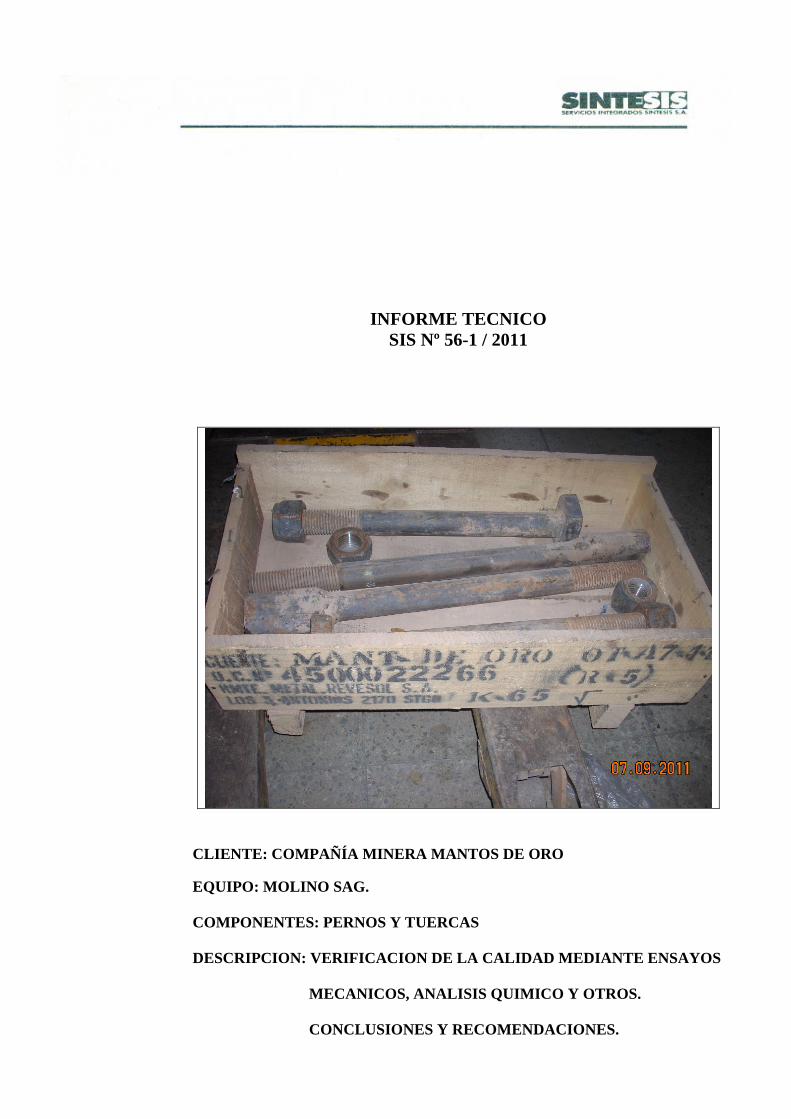
INFORME TECNICO SIS Nº 56-1 / 2011
CLIENTE: COMPAÑÍA MINERA MANTOS DE ORO EQUIPO: MOLINO SAG. COMPONENTES: PERNOS Y TUERCAS DESCRIPCION: VERIFICACION DE LA CALIDAD MEDIANTE ENSAYOS MECANICOS, ANALISIS QUIMICO Y OTROS. CONCLUSIONES Y RECOMENDACIONES.
INFORME TÉCNICO SIS Nº 56-1 / 2011
CLIENTE: COMPAÑÍA MINERA MANTOS DE ORO EQUIPO: MOLINO SAG
DESCRIPCIÓN: VERIFICACIÓN DE LA CALIDAD DE 4 CONJUNTOS DE PERNOS Y TUERCAS. CONCLUSIONES Y RECOMENDACIONES.
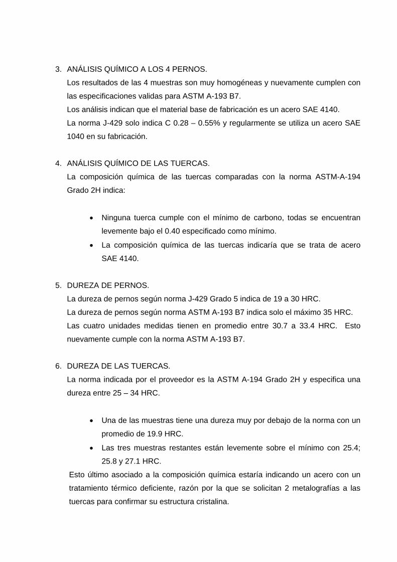
1. INTRODUCCIÓN
Mantos de Oro, ha considerado necesario verificar la calidad de los pernos y tuercas
que se estan utilizando actualmente. Esto debido a que ha observado una mayor
filtración y sospecha que algo no esta funcionando adecuadamente en el apriete de
los pernos.
Para dicha investigación Mantos de Oro procede a enviar 4 pernos 2 cabeza
ovalada y 2 cabeza cuadrada con sus correspondientes 4 tuercas. Tambien adjunta
hoja de especificaciones de TORQUE suministrada por el fabricante de los lifter.
Además informa que estos pernos se compran con especificaciones del fabricante
según las siguientes normas:
Para Perno 2”: SAE J429 Grado 5
Tuerca 2”: ASTM A-194 Grado 2H.
El presente informe detalla los resultados de los análisis químicos, ensayos
mecánicos, medición de durezas y algunas metalografías realizadas a las tuercas, e
Indica las conclusiones finales y agrega algunas recomendaciones.
2. COMENTARIOS SOBRE ENSAYOS DE TRACCIÓN A 4 PERNOS.
Realizados los ensayos mecánicos a los 4 pernos se puede observar que los
valores de: área inicial, carga de fluencia, carga máxima, tensión de fluencia, tensión
máxima, alargamiento y reducción de área: son cumplidos con largueza por las 4
unidades.
Más aun, estos pernos están en un nivel superior a la Norma J429 la cual no cubre
el diámetro 2”(solo alcanza a 1 ½”).
Los 4 pernos según sus propiedades mecánicas se clasifican en la norma
ASTM-A-193-B7.
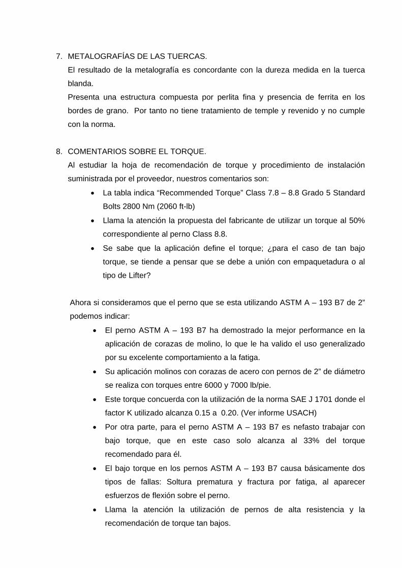
3. ANÁLISIS QUÍMICO A LOS 4 PERNOS.
Los resultados de las 4 muestras son muy homogéneas y nuevamente cumplen con
las especificaciones validas para ASTM A-193 B7.
Los análisis indican que el material base de fabricación es un acero SAE 4140.
La norma J-429 solo indica C 0.28 – 0.55% y regularmente se utiliza un acero SAE
1040 en su fabricación.
4. ANÁLISIS QUÍMICO DE LAS TUERCAS.
La composición química de las tuercas comparadas con la norma ASTM-A-194
Grado 2H indica:
• Ninguna tuerca cumple con el mínimo de carbono, todas se encuentran
levemente bajo el 0.40 especificado como mínimo.
• La composición química de las tuercas indicaría que se trata de acero
SAE 4140.
5. DUREZA DE PERNOS.
La dureza de pernos según norma J-429 Grado 5 indica de 19 a 30 HRC.
La dureza de pernos según norma ASTM A-193 B7 indica solo el máximo 35 HRC.
Las cuatro unidades medidas tienen en promedio entre 30.7 a 33.4 HRC. Esto
nuevamente cumple con la norma ASTM A-193 B7.
6. DUREZA DE LAS TUERCAS.
La norma indicada por el proveedor es la ASTM A-194 Grado 2H y especifica una
dureza entre 25 – 34 HRC.
• Una de las muestras tiene una dureza muy por debajo de la norma con un
promedio de 19.9 HRC.
• Las tres muestras restantes están levemente sobre el mínimo con 25.4;
25.8 y 27.1 HRC.
Esto último asociado a la composición química estaría indicando un acero con un
tratamiento térmico deficiente, razón por la que se solicitan 2 metalografías a las
tuercas para confirmar su estructura cristalina.
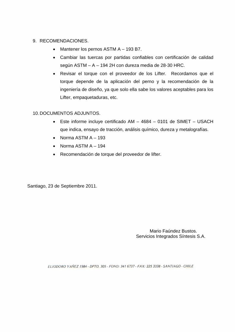
7. METALOGRAFÍAS DE LAS TUERCAS.
El resultado de la metalografía es concordante con la dureza medida en la tuerca
blanda.
Presenta una estructura compuesta por perlita fina y presencia de ferrita en los
bordes de grano. Por tanto no tiene tratamiento de temple y revenido y no cumple
con la norma.
8. COMENTARIOS SOBRE EL TORQUE.
Al estudiar la hoja de recomendación de torque y procedimiento de instalación
suministrada por el proveedor, nuestros comentarios son:
• La tabla indica “Recommended Torque” Class 7.8 – 8.8 Grado 5 Standard
Bolts 2800 Nm (2060 ft-lb)
• Llama la atención la propuesta del fabricante de utilizar un torque al 50%
correspondiente al perno Class 8.8.
• Se sabe que la aplicación define el torque; ¿para el caso de tan bajo
torque, se tiende a pensar que se debe a unión con empaquetadura o al
tipo de Lifter?
Ahora si consideramos que el perno que se esta utilizando ASTM A – 193 B7 de 2”
podemos indicar:
• El perno ASTM A – 193 B7 ha demostrado la mejor performance en la
aplicación de corazas de molino, lo que le ha valido el uso generalizado
por su excelente comportamiento a la fatiga.
• Su aplicación molinos con corazas de acero con pernos de 2” de diámetro
se realiza con torques entre 6000 y 7000 lb/pie.
• Este torque concuerda con la utilización de la norma SAE J 1701 donde el
factor K utilizado alcanza 0.15 a 0.20. (Ver informe USACH)
• Por otra parte, para el perno ASTM A – 193 B7 es nefasto trabajar con
bajo torque, que en este caso solo alcanza al 33% del torque
recomendado para él.
• El bajo torque en los pernos ASTM A – 193 B7 causa básicamente dos
tipos de fallas: Soltura prematura y fractura por fatiga, al aparecer
esfuerzos de flexión sobre el perno.
• Llama la atención la utilización de pernos de alta resistencia y la
recomendación de torque tan bajos.
9. RECOMENDACIONES.
• Mantener los pernos ASTM A – 193 B7.
• Cambiar las tuercas por partidas confiables con certificación de calidad
según ASTM – A – 194 2H con dureza media de 28-30 HRC.
• Revisar el torque con el proveedor de los Lifter. Recordamos que el
torque depende de la aplicación del perno y la recomendación de la
ingeniería de diseño, ya que solo ella sabe los valores aceptables para los
Lifter, empaquetaduras, etc.
10. DOCUMENTOS ADJUNTOS.
• Este informe incluye certificado AM – 4684 – 0101 de SIMET – USACH
que indica, ensayo de tracción, análisis químico, dureza y metalografías.
• Norma ASTM A – 193
• Norma ASTM A – 194
• Recomendación de torque del proveedor de lifter.
Santiago, 23 de Septiembre 2011.
Mario Faúndez Bustos.
Servicios Integrados Síntesis S.A.
INFORME DE RESULTADOS Fecha: 22 de Septiembre de 2011 AM-4684-0101 Revisión: 01.-
SINTESIS Página 1 de 15
UNIVERSIDAD DE SANTIAGO DE CHILE
Departamento de Ingeniería Metalúrgica Laboratorio de Ensayos e Investigación de Materiales SIMET-USACH
Av. Ecuador 3769, Estación Central-Santiago-Chile Fono-Fax: 56-2-3234780, Email: [email protected]
www.simet.usach.cl
Cliente : Servicios Integrados Síntesis. Dirección : Eliodoro Yánez Nº 1984 oficina 305, Providencia, Santiago. Tipo de Muestra : Material metálico. Cantidad : 04 Tipo de Ensayo : Ensayo de Tracción,
Químico y Dureza. Fecha de Recepción : 07-09-11
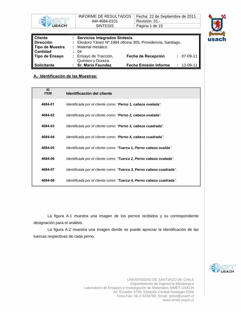
Solicitante : Sr. Mario Faundez. Fecha Emisión Informe : 12-09-11 A.- Identificación de las Muestras:
ID ITEM Identificación del cliente
4684-01 Identificada por el cliente como: “Perno 1, cabeza ovalada”.
4684-02 Identificada por el cliente como: “Perno 2, cabeza ovalada”.
4684-03 Identificada por el cliente como: “Perno 3, cabeza cuadrada”.
4684-04 Identificada por el cliente como: “Perno 4, cabeza cuadrada”.
4684-05 Identificada por el cliente como: “Tuerca 1, Perno cabeza ovalda”.
4684-06 Identificada por el cliente como: “Tuerca 2, Perno cabeza ovalada”.
4684-07 Identificada por el cliente como: “Tuerca 3, Perno cabeza cuadrada”.
4684-08 Identificada por el cliente como: “Tuerca 4, Perno cabeza cuadrada”.
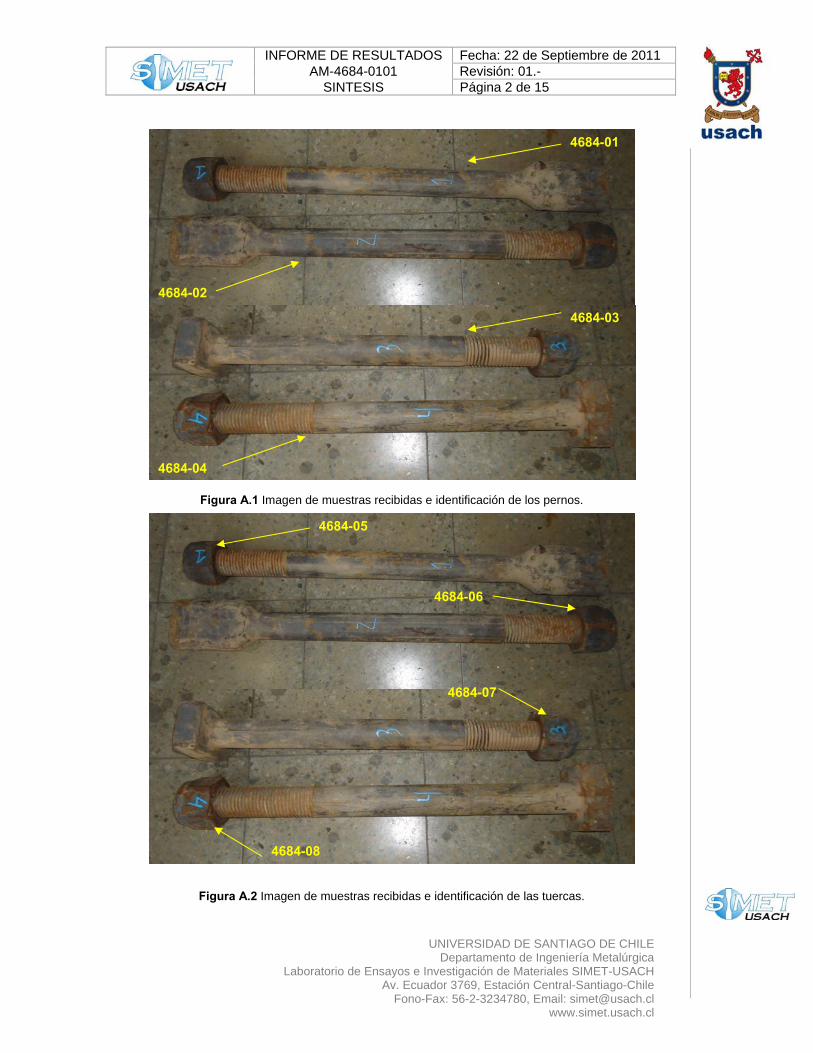
La figura A.1 muestra una imagen de los pernos recibidos y su correspondiente
designación para el análisis.
La figura A.2 muestra una imagen donde se puede apreciar la identificación de las
tuercas respectivas de cada perno.
INFORME DE RESULTADOS Fecha: 22 de Septiembre de 2011 AM-4684-0101 Revisión: 01.-
SINTESIS Página 2 de 15
UNIVERSIDAD DE SANTIAGO DE CHILE
Departamento de Ingeniería Metalúrgica Laboratorio de Ensayos e Investigación de Materiales SIMET-USACH
Av. Ecuador 3769, Estación Central-Santiago-Chile Fono-Fax: 56-2-3234780, Email: [email protected]
www.simet.usach.cl
Figura A.1 Imagen de muestras recibidas e identificación de los pernos.
Figura A.2 Imagen de muestras recibidas e identificación de las tuercas.
4684-01
4684-02
4684-03
4684-04
4684-05
4684-06
4684-07
4684-08
INFORME DE RESULTADOS Fecha: 22 de Septiembre de 2011 AM-4684-0101 Revisión: 01.-
SINTESIS Página 3 de 15
UNIVERSIDAD DE SANTIAGO DE CHILE
Departamento de Ingeniería Metalúrgica Laboratorio de Ensayos e Investigación de Materiales SIMET-USACH
Av. Ecuador 3769, Estación Central-Santiago-Chile Fono-Fax: 56-2-3234780, Email: [email protected]
www.simet.usach.cl
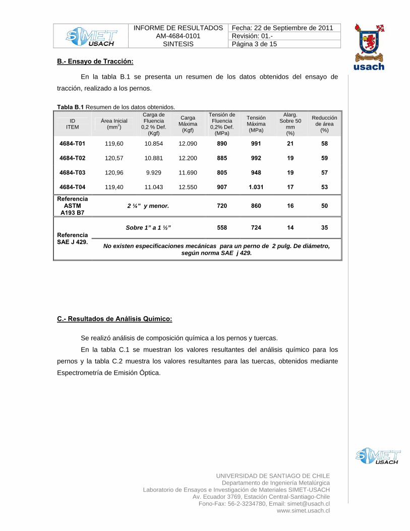
B.- Ensayo de Tracción:
En la tabla B.1 se presenta un resumen de los datos obtenidos del ensayo de
tracción, realizado a los pernos.
Tabla B.1 Resumen de los datos obtenidos.
ID ITEM
Área Inicial (mm2)
Carga de Fluencia
0,2 % Def. (Kgf)
Carga Máxima
(Kgf)
Tensión de Fluencia
0,2% Def. (MPa)
Tensión Máxima (MPa)
Alarg. Sobre 50
mm (%)
Reducción de área
(%)
4684-T01 119,60 10.854 12.090 890 991 21 58
4684-T02 120,57 10.881 12.200 885 992 19 59
4684-T03 120,96 9.929 11.690 805 948 19 57
4684-T04 119,40 11.043 12.550 907 1.031 17 53
Referencia ASTM
A193 B7 2 ¼” y menor. 720 860 16 50
Referencia SAE J 429.
Sobre 1” a 1 ½” 558 724 14 35
No existen especificaciones mecánicas para un perno de 2 pulg. De diámetro, según norma SAE j 429.
C.- Resultados de Análisis Químico:
Se realizó análisis de composición química a los pernos y tuercas.
En la tabla C.1 se muestran los valores resultantes del análisis químico para los
pernos y la tabla C.2 muestra los valores resultantes para las tuercas, obtenidos mediante
Espectrometría de Emisión Óptica.
INFORME DE RESULTADOS Fecha: 22 de Septiembre de 2011 AM-4684-0101 Revisión: 01.-
SINTESIS Página 4 de 15
UNIVERSIDAD DE SANTIAGO DE CHILE
Departamento de Ingeniería Metalúrgica Laboratorio de Ensayos e Investigación de Materiales SIMET-USACH
Av. Ecuador 3769, Estación Central-Santiago-Chile Fono-Fax: 56-2-3234780, Email: [email protected]
www.simet.usach.cl
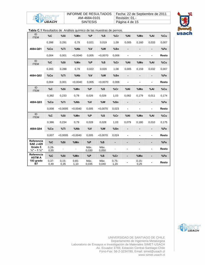
Tabla C.1 Resultados de Análisis químico de las muestras de pernos. ID
ITEM %C %Si %Mn %P %S %Cr %Ni %Mo %Al %Cu
4684-Q01
0,398 0,291 0,79 0,021 0,019 1,09 0,005 0,160 0,033 0,007
%Co %Ti %Nb %V %W %Sn - - - %Fe
0,004 0,001 <0,0040 0,005 <0,0070 0,006 - - - Resto
ID ITEM %C %Si %Mn %P %S %Cr %Ni %Mo %Al %Cu
4684-Q02
0,393 0,288 0,79 0,022 0,020 1,08 0,005 0,159 0,032 0,007
%Co %Ti %Nb %V %W %Sn - - - %Fe
0,004 0,001 <0,0040 0,005 <0,0070 0,006 - - - Resto
ID ITEM %C %Si %Mn %P %S %Cr %Ni %Mo %Al %Cu
4684-Q03
0,382 0,233 0,78 0,026 0,026 1,03 0,082 0,179 0,011 0,174
%Co %Ti %Nb %V %W %Sn - - - %Fe
0,008 <0,0005 <0,0040 0,005 <0,0070 0,023 - - - Resto
ID ITEM %C %Si %Mn %P %S %Cr %Ni %Mo %Al %Cu
4684-Q04
0,386 0,234 0,79 0,028 0,028 1,03 0,079 0,180 0,010 0,175
%Co %Ti %Nb %V %W %Sn - - - %Fe
0,007 <0,0005 <0,0040 0,005 <0,0070 0,024 - - - Resto
Referencia SAE J-429 Grado 5
¼” – 1 ½”
%C %Si %Mn %P %S - - - - %Fe
0,28-0,55 - - Máx.
0,030 Máx. 0,050 - - - - Resto
Referencia ASTM A
193 grado B7
%C %Si %Mn %P %S %Cr - %Mo - %Fe
0,37-0,49
0,15-0,35
0,65-1,10
Máx. 0,035
Máx. 0,040
0,75-1,20 - 0,15-
0,25 - Resto
INFORME DE RESULTADOS Fecha: 22 de Septiembre de 2011 AM-4684-0101 Revisión: 01.-
SINTESIS Página 5 de 15
UNIVERSIDAD DE SANTIAGO DE CHILE
Departamento de Ingeniería Metalúrgica Laboratorio de Ensayos e Investigación de Materiales SIMET-USACH
Av. Ecuador 3769, Estación Central-Santiago-Chile Fono-Fax: 56-2-3234780, Email: [email protected]
www.simet.usach.cl
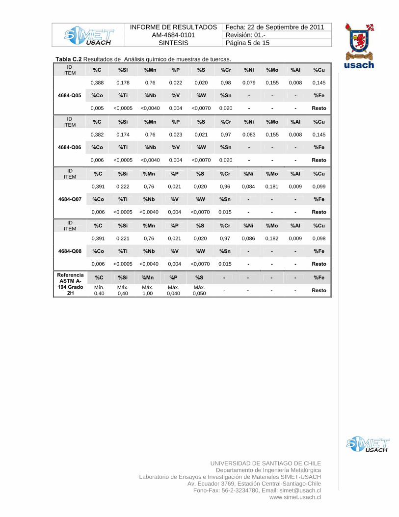
Tabla C.2 Resultados de Análisis químico de muestras de tuercas. ID
ITEM %C %Si %Mn %P %S %Cr %Ni %Mo %Al %Cu
4684-Q05
0,388 0,178 0,76 0,022 0,020 0,98 0,079 0,155 0,008 0,145
%Co %Ti %Nb %V %W %Sn - - - %Fe
0,005 <0,0005 <0,0040 0,004 <0,0070 0,020 - - - Resto
ID ITEM %C %Si %Mn %P %S %Cr %Ni %Mo %Al %Cu
4684-Q06
0,382 0,174 0,76 0,023 0,021 0,97 0,083 0,155 0,008 0,145
%Co %Ti %Nb %V %W %Sn - - - %Fe
0,006 <0,0005 <0,0040 0,004 <0,0070 0,020 - - - Resto
ID ITEM %C %Si %Mn %P %S %Cr %Ni %Mo %Al %Cu
4684-Q07
0,391 0,222 0,76 0,021 0,020 0,96 0,084 0,181 0,009 0,099
%Co %Ti %Nb %V %W %Sn - - - %Fe
0,006 <0,0005 <0,0040 0,004 <0,0070 0,015 - - - Resto
ID ITEM %C %Si %Mn %P %S %Cr %Ni %Mo %Al %Cu
4684-Q08
0,391 0,221 0,76 0,021 0,020 0,97 0,086 0,182 0,009 0,098
%Co %Ti %Nb %V %W %Sn - - - %Fe
0,006 <0,0005 <0,0040 0,004 <0,0070 0,015 - - - Resto
Referencia ASTM A-
194 Grado 2H
%C %Si %Mn %P %S - - - - %Fe
Mín. 0,40
Máx. 0,40
Máx. 1,00
Máx. 0,040
Máx. 0,050 - - - - Resto
INFORME DE RESULTADOS Fecha: 22 de Septiembre de 2011 AM-4684-0101 Revisión: 01.-
SINTESIS Página 6 de 15
UNIVERSIDAD DE SANTIAGO DE CHILE
Departamento de Ingeniería Metalúrgica Laboratorio de Ensayos e Investigación de Materiales SIMET-USACH
Av. Ecuador 3769, Estación Central-Santiago-Chile Fono-Fax: 56-2-3234780, Email: [email protected]
www.simet.usach.cl
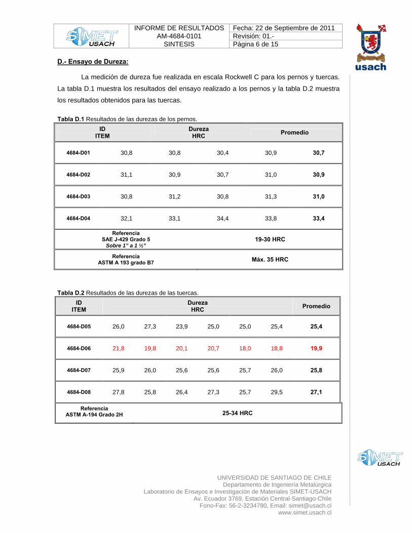
D.- Ensayo de Dureza: La medición de dureza fue realizada en escala Rockwell C para los pernos y tuercas.
La tabla D.1 muestra los resultados del ensayo realizado a los pernos y la tabla D.2 muestra
los resultados obtenidos para las tuercas.
Tabla D.1 Resultados de las durezas de los pernos.
ID ITEM
Dureza HRC Promedio
4684-D01 30,8 30,8 30,4 30,9 30,7
4684-D02 31,1 30,9 30,7 31,0 30,9
4684-D03 30,8 31,2 30,8 31,3 31,0
4684-D04 32,1 33,1 34,4 33,8 33,4
Referencia SAE J-429 Grado 5
Sobre 1” a 1 ½” 19-30 HRC
Referencia ASTM A 193 grado B7 Máx. 35 HRC
Tabla D.2 Resultados de las durezas de las tuercas.
ID ITEM
Dureza HRC Promedio
4684-D05 26,0 27,3 23,9 25,0 25,0 25,4 25,4
4684-D06 21,8 19,8 20,1 20,7 18,0 18,8 19,9
4684-D07 25,9 26,0 25,6 25,6 25,7 26,0 25,8
4684-D08 27,8 25,8 26,4 27,3 25,7 29,5 27,1
Referencia ASTM A-194 Grado 2H 25-34 HRC
INFORME DE RESULTADOS Fecha: 22 de Septiembre de 2011 AM-4684-0101 Revisión: 01.-
SINTESIS Página 7 de 15
UNIVERSIDAD DE SANTIAGO DE CHILE
Departamento de Ingeniería Metalúrgica Laboratorio de Ensayos e Investigación de Materiales SIMET-USACH
Av. Ecuador 3769, Estación Central-Santiago-Chile Fono-Fax: 56-2-3234780, Email: [email protected]
www.simet.usach.cl
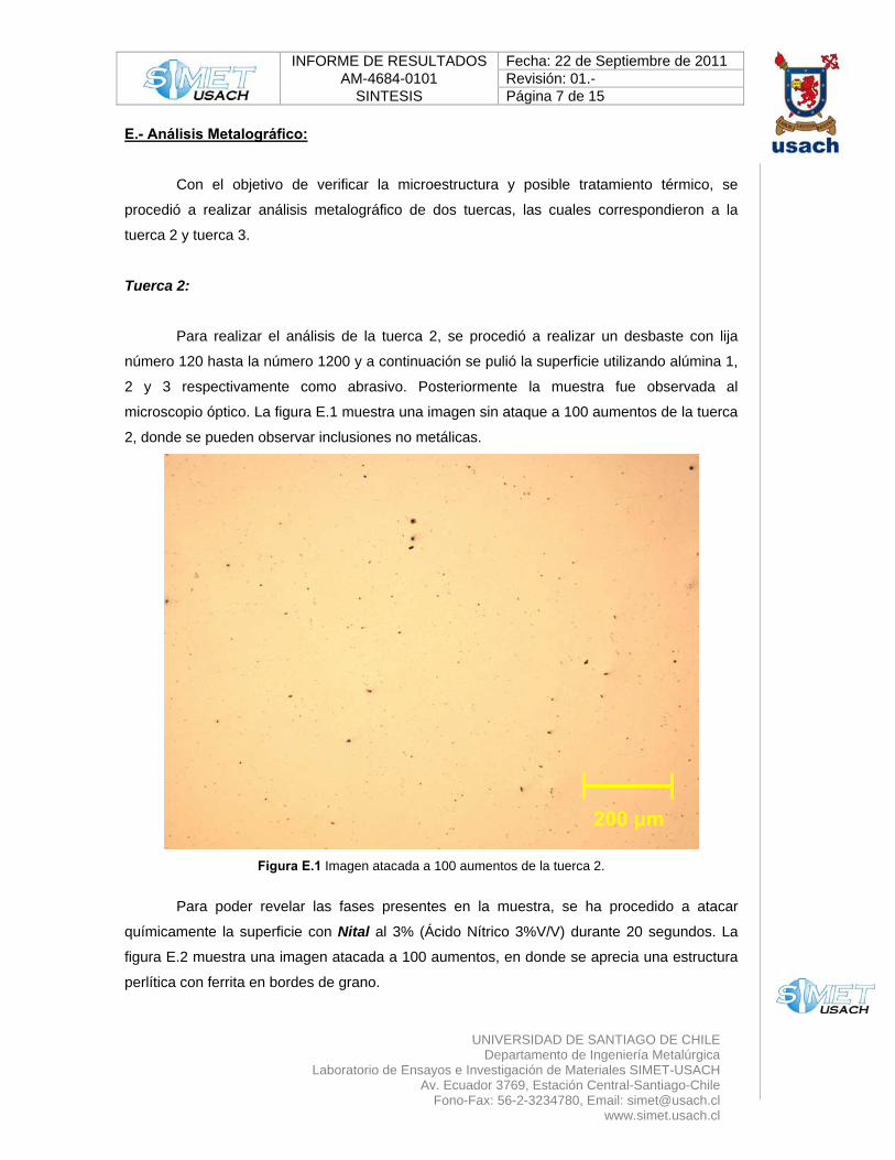
E.- Análisis Metalográfico:
Con el objetivo de verificar la microestructura y posible tratamiento térmico, se
procedió a realizar análisis metalográfico de dos tuercas, las cuales correspondieron a la
tuerca 2 y tuerca 3.
Tuerca 2: Para realizar el análisis de la tuerca 2, se procedió a realizar un desbaste con lija
número 120 hasta la número 1200 y a continuación se pulió la superficie utilizando alúmina 1,
2 y 3 respectivamente como abrasivo. Posteriormente la muestra fue observada al
microscopio óptico. La figura E.1 muestra una imagen sin ataque a 100 aumentos de la tuerca
2, donde se pueden observar inclusiones no metálicas.
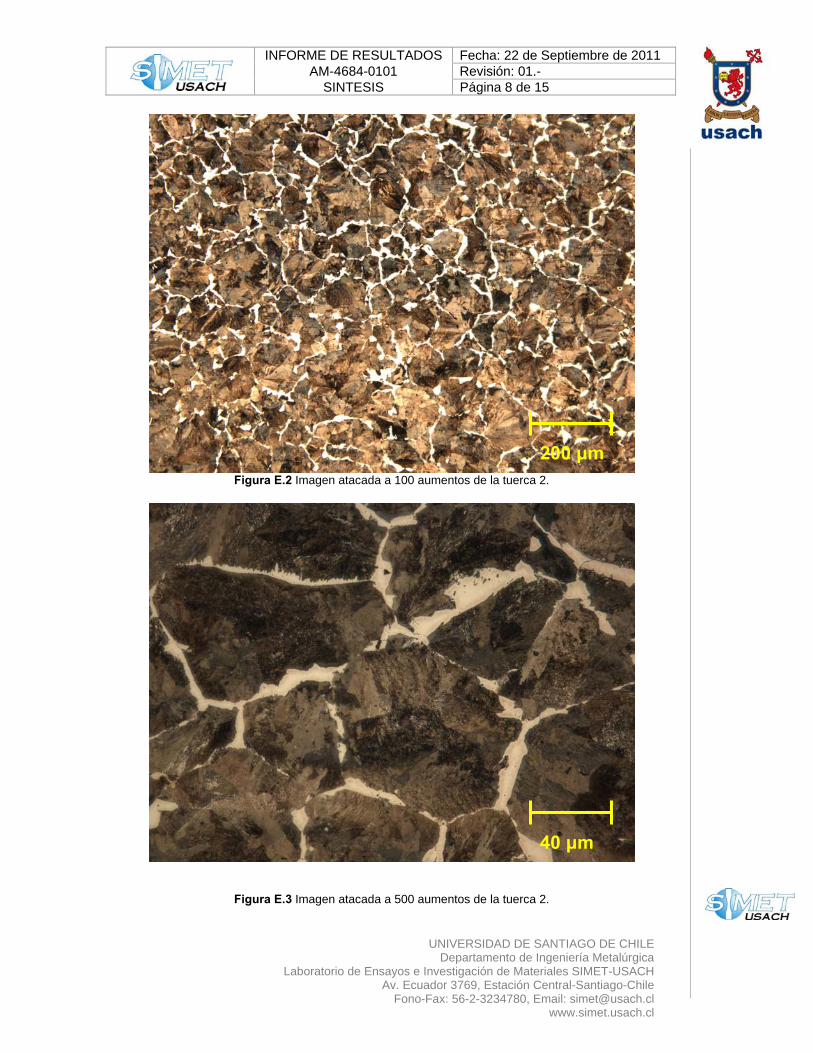
Figura E.1 Imagen atacada a 100 aumentos de la tuerca 2. Para poder revelar las fases presentes en la muestra, se ha procedido a atacar
químicamente la superficie con Nital al 3% (Ácido Nítrico 3%V/V) durante 20 segundos. La
figura E.2 muestra una imagen atacada a 100 aumentos, en donde se aprecia una estructura
perlítica con ferrita en bordes de grano.
200 μm
INFORME DE RESULTADOS Fecha: 22 de Septiembre de 2011 AM-4684-0101 Revisión: 01.-
SINTESIS Página 8 de 15
UNIVERSIDAD DE SANTIAGO DE CHILE
Departamento de Ingeniería Metalúrgica Laboratorio de Ensayos e Investigación de Materiales SIMET-USACH
Av. Ecuador 3769, Estación Central-Santiago-Chile Fono-Fax: 56-2-3234780, Email: [email protected]
www.simet.usach.cl
Figura E.2 Imagen atacada a 100 aumentos de la tuerca 2.
Figura E.3 Imagen atacada a 500 aumentos de la tuerca 2.
40 μm
200 μm
INFORME DE RESULTADOS Fecha: 22 de Septiembre de 2011 AM-4684-0101 Revisión: 01.-
SINTESIS Página 9 de 15
UNIVERSIDAD DE SANTIAGO DE CHILE
Departamento de Ingeniería Metalúrgica Laboratorio de Ensayos e Investigación de Materiales SIMET-USACH
Av. Ecuador 3769, Estación Central-Santiago-Chile Fono-Fax: 56-2-3234780, Email: [email protected]
www.simet.usach.cl
La figura E.3 muestra una imagen atacada a 500 aumentos de la tuerca 2, donde se
puede observar una microestructura compuesta por perlita fina y presencia de ferrita en los
bordes de grano.
La estructura no es coincidente con un tratamiento térmico de temple y revenido.
Tuerca 3:
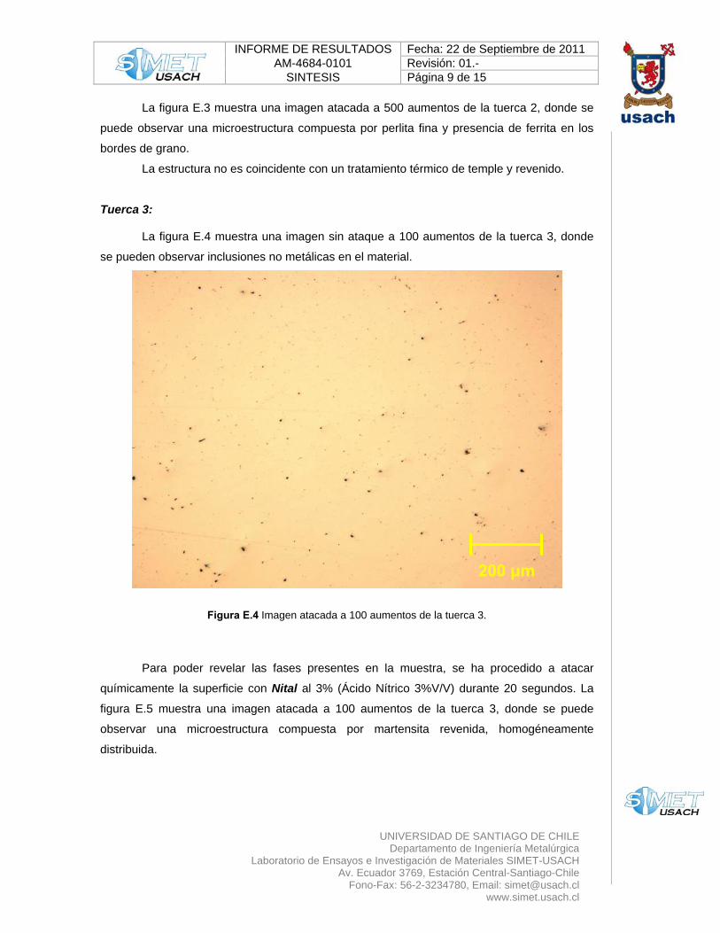
La figura E.4 muestra una imagen sin ataque a 100 aumentos de la tuerca 3, donde
se pueden observar inclusiones no metálicas en el material.
Figura E.4 Imagen atacada a 100 aumentos de la tuerca 3.
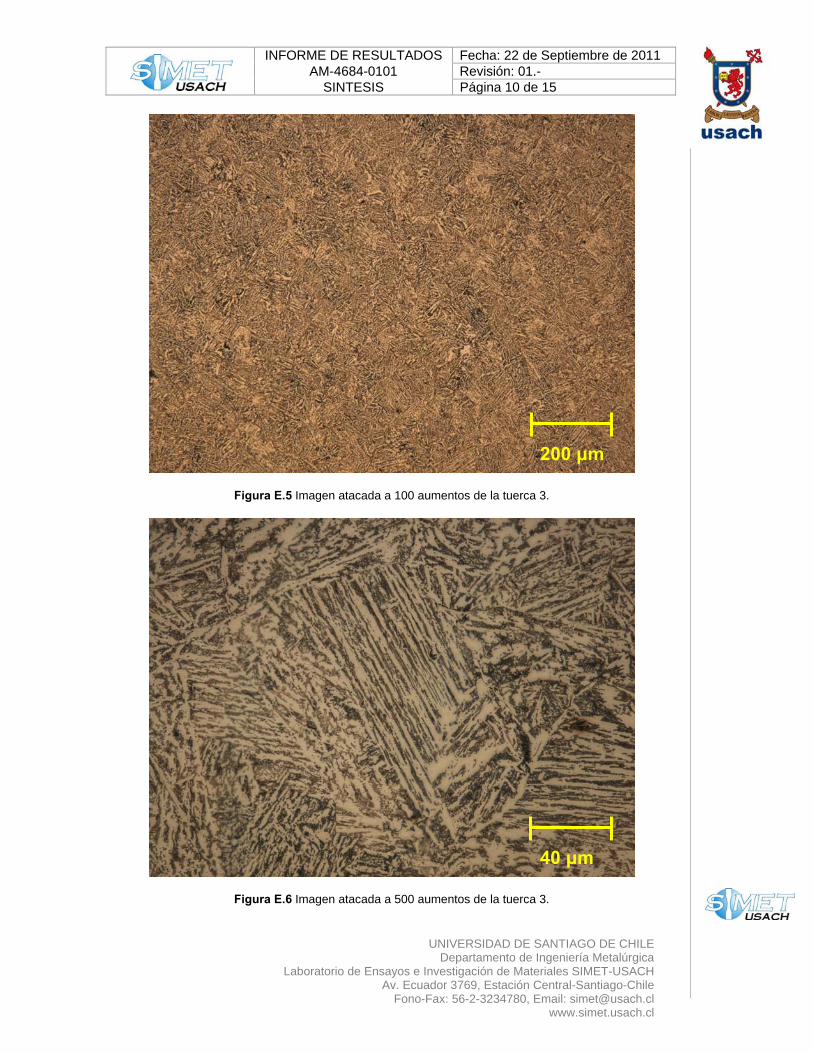
Para poder revelar las fases presentes en la muestra, se ha procedido a atacar
químicamente la superficie con Nital al 3% (Ácido Nítrico 3%V/V) durante 20 segundos. La
figura E.5 muestra una imagen atacada a 100 aumentos de la tuerca 3, donde se puede
observar una microestructura compuesta por martensita revenida, homogéneamente
distribuida.
200 μm
INFORME DE RESULTADOS Fecha: 22 de Septiembre de 2011 AM-4684-0101 Revisión: 01.-
SINTESIS Página 10 de 15
UNIVERSIDAD DE SANTIAGO DE CHILE
Departamento de Ingeniería Metalúrgica Laboratorio de Ensayos e Investigación de Materiales SIMET-USACH
Av. Ecuador 3769, Estación Central-Santiago-Chile Fono-Fax: 56-2-3234780, Email: [email protected]
www.simet.usach.cl
Figura E.5 Imagen atacada a 100 aumentos de la tuerca 3.
Figura E.6 Imagen atacada a 500 aumentos de la tuerca 3.
200 μm
40 μm
INFORME DE RESULTADOS Fecha: 22 de Septiembre de 2011 AM-4684-0101 Revisión: 01.-
SINTESIS Página 11 de 15
UNIVERSIDAD DE SANTIAGO DE CHILE
Departamento de Ingeniería Metalúrgica Laboratorio de Ensayos e Investigación de Materiales SIMET-USACH
Av. Ecuador 3769, Estación Central-Santiago-Chile Fono-Fax: 56-2-3234780, Email: [email protected]
www.simet.usach.cl
La figura E.6 muestra una imagen atacada a 500 aumentos de la tuerca 3, donde se puede
observar martensita revenida en su microestructura, característica de un tratamiento térmico
de temple y revenido.
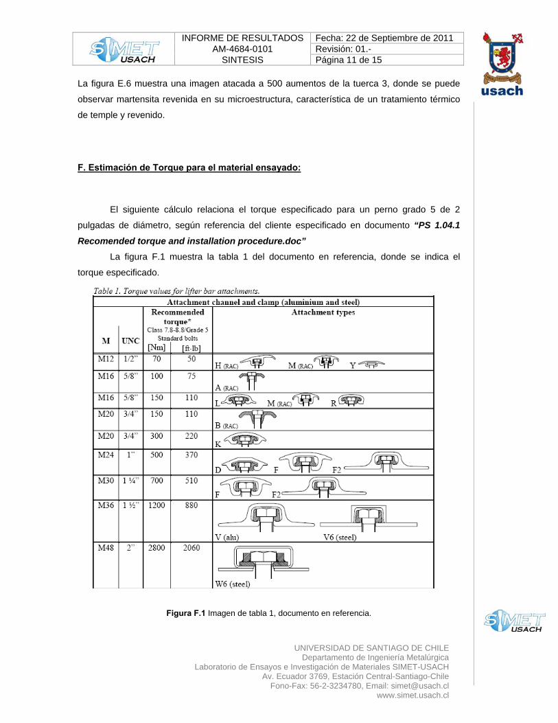
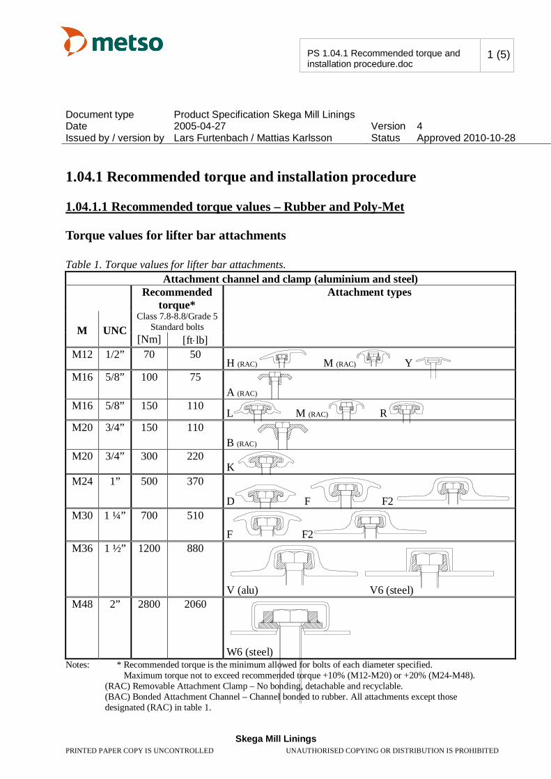
F. Estimación de Torque para el material ensayado: El siguiente cálculo relaciona el torque especificado para un perno grado 5 de 2
pulgadas de diámetro, según referencia del cliente especificado en documento “PS 1.04.1
Recomended torque and installation procedure.doc” La figura F.1 muestra la tabla 1 del documento en referencia, donde se indica el
torque especificado.
Figura F.1 Imagen de tabla 1, documento en referencia.
INFORME DE RESULTADOS Fecha: 22 de Septiembre de 2011 AM-4684-0101 Revisión: 01.-
SINTESIS Página 12 de 15
UNIVERSIDAD DE SANTIAGO DE CHILE
Departamento de Ingeniería Metalúrgica Laboratorio de Ensayos e Investigación de Materiales SIMET-USACH
Av. Ecuador 3769, Estación Central-Santiago-Chile Fono-Fax: 56-2-3234780, Email: [email protected]
www.simet.usach.cl
El documento indica según tabla que el torque recomendado correspondiente para un
perno de 2”, es equivalente a 2.800 Nm o 2060 ft·lb.
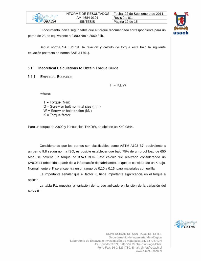
Según norma SAE J1701, la relación y cálculo de torque está bajo la siguiente
ecuación (extracto de norma SAE J 1701).
Para un torque de 2.800 y la ecuación T=KDW, se obtiene un K=0,0844. Considerando que los pernos son clasificables como ASTM A193 B7, equivalente a
un perno 9.8 según norma ISO, es posible establecer que bajo 75% de un proof load de 650
Mpa, se obtiene un torque de 3.571 N·m. Este cálculo fue realizado considerando un
K=0,0844 (obtenido a partir de la información del fabricante), lo que es considerado un K bajo.
Normalmente el K se encuentra en un rango de 0,10 a 0,15, para materiales con golilla.
Es importante señalar que el factor K, tiene importante significancia en el torque a
aplicar.
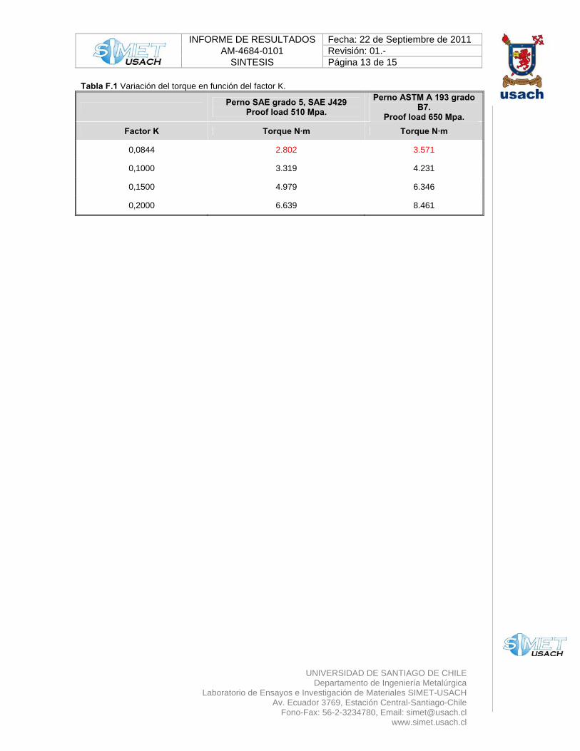
La tabla F.1 muestra la variación del torque aplicado en función de la variación del
factor K.
INFORME DE RESULTADOS Fecha: 22 de Septiembre de 2011 AM-4684-0101 Revisión: 01.-
SINTESIS Página 13 de 15
UNIVERSIDAD DE SANTIAGO DE CHILE
Departamento de Ingeniería Metalúrgica Laboratorio de Ensayos e Investigación de Materiales SIMET-USACH
Av. Ecuador 3769, Estación Central-Santiago-Chile Fono-Fax: 56-2-3234780, Email: [email protected]
www.simet.usach.cl
Tabla F.1 Variación del torque en función del factor K.
Perno SAE grado 5, SAE J429 Proof load 510 Mpa.
Perno ASTM A 193 grado B7.
Proof load 650 Mpa. Factor K Torque N·m Torque N·m
0,0844 2.802 3.571
0,1000 3.319 4.231
0,1500 4.979 6.346
0,2000 6.639 8.461
INFORME DE RESULTADOS Fecha: 22 de Septiembre de 2011 AM-4684-0101 Revisión: 01.-
SINTESIS Página 14 de 15
UNIVERSIDAD DE SANTIAGO DE CHILE
Departamento de Ingeniería Metalúrgica Laboratorio de Ensayos e Investigación de Materiales SIMET-USACH
Av. Ecuador 3769, Estación Central-Santiago-Chile Fono-Fax: 56-2-3234780, Email: [email protected]
www.simet.usach.cl
G.- Comentarios:
De los análisis realizados, es posible decir lo siguiente:
G.1 Referente a su clasificación: Respecto de los pernos:
Los pernos no son clasificable bajo norma SAE J 429 Grado 5, ya que estos
presentan diámetros superiores a lo especificado por la norma (diámetro menor a 1 ½”).
Los pernos pueden ser clasificados bajo norma ASTM A 193 grado B7, cumpliendo
con las propiedades mecánicas, composición química y dureza.
Respecto a las tuercas: Es posible decir que las cuatro muestras, no cumplen con el mínimo exigido en el
porcentaje de carbono, para la norma ASTM A 194 2H.
La tuerca identificada como tuerca 2, perno cabeza ovalada, además, no cumple con
la dureza exigida por la norma ASTM A 194 2H. G.2 Referente al análisis metalográfico de las tuercas: Es posible decir que las tuercas analizadas presentaron tratamientos térmicos
diferentes, siendo la tuerca 2 la muestra con menor dureza y una microestructura coherente
con esta baja dureza, compuesta por perlita fina y ferrita en bordes de grano. La tuerca 2 no
presenta un tratamiento térmico de temple y revenido o tratamiento térmico deficiente.
La tuerca clasificada como 3, presenta una microestructura de martensita revenida, lo
que es coherente con un tratamiento térmico de temple y revenido. G.3 Referente al torque de los pernos: Es posible decir que en revisión de los torques recomendados para un perno grado 5
según SAE J 429 y para un ASTM A193 grado B7, los torque tienen diferencias en sus
magnitudes, por lo que es posible suponer que si los pernos clasificados como ASTM A 193
grado B7 fueron torqueados bajo la especificación de un perno grado 5 SAE J429, el torque
se encontraría por debajo de lo recomendado.
No es posible establecer el grado de incidencia en la prestación ya que se
desconocen las condiciones de esfuerzos del conjunto en servicio.
INFORME DE RESULTADOS Fecha: 22 de Septiembre de 2011 AM-4684-0101 Revisión: 01.-
SINTESIS Página 15 de 15
UNIVERSIDAD DE SANTIAGO DE CHILE
Departamento de Ingeniería Metalúrgica Laboratorio de Ensayos e Investigación de Materiales SIMET-USACH
Av. Ecuador 3769, Estación Central-Santiago-Chile Fono-Fax: 56-2-3234780, Email: [email protected]
www.simet.usach.cl
NOTAS:
Los resultados obtenidos son válidos sólo para las muestras ensayadas y entregadas por el cliente. Este informe no puede ser reproducido parcial ni totalmente sin la aprobación escrita del laboratorio. El laboratorio SIMET-USACH no se responsabiliza por las muestras ensayadas a contar de 30 días de la
fecha de emisión de informe. Los ensayos de tracción fueron realizados en una máquina de tracción marca Tinius & Olsen Mod. Súper L,
con capacidad para 30 toneladas (certificado de calibración IDIC Nº F-792, con fecha 08 julio de 2010). Los ensayos fueron realizados con un espectrómetro de emisión de lectura directa, modelo
SPECTROMAXx. Las mediciones de dureza fueron realizadas en un durómetro con reporte de datos digital, marca Emco
Test tipo M4R 075.
Dr. Ing. Alfredo Artigas A.
Gerente Técnico.
Ing. Alejandro Castillo A.
Departamento de Ing. Metalúrgica.
Document type Product Specification Skega Mill Linings Date 2005-04-27 Version 4 Issued by / version by Lars Furtenbach / Mattias Karlsson Status Approved 2010-10-28
Skega Mill Linings
PRINTED PAPER COPY IS UNCONTROLLED UNAUTHORISED COPYING OR DISTRIBUTION IS PROHIBITED
PS 1.04.1 Recommended torque and installation procedure.doc
1 (5)
1.04.1 Recommended torque and installation procedure
1.04.1.1 Recommended torque values – Rubber and Poly-Met
Torque values for lifter bar attachments Table 1. Torque values for lifter bar attachments.
Attachment channel and clamp (aluminium and steel) Recommended
torque* Attachment types
M
UNC
Class 7.8-8.8/Grade 5 Standard bolts
[Nm] [ft lb] M12 1/2” 70 50
H (RAC) M (RAC) Y M16 5/8” 100 75
A (RAC) M16 5/8” 150 110
L M (RAC) R M20 3/4” 150 110
B (RAC) M20 3/4” 300 220
K M24 1” 500 370
D F F2 M30 1 ¼” 700 510
F F2 M36 1 ½” 1200 880
V (alu) V6 (steel)
M48 2” 2800 2060
W6 (steel)
Notes: * Recommended torque is the minimum allowed for bolts of each diameter specified. Maximum torque not to exceed recommended torque +10% (M12-M20) or +20% (M24-M48). (RAC) Removable Attachment Clamp – No bonding, detachable and recyclable. (BAC) Bonded Attachment Channel – Channel bonded to rubber. All attachments except those
designated (RAC) in table 1.
Document type Product Specification Skega Mill Linings Date 2005-04-27 Version 4 Issued by / version by Lars Furtenbach / Mattias Karlsson Status Approved 2010-10-28
Skega Mill Linings
PRINTED PAPER COPY IS UNCONTROLLED UNAUTHORISED COPYING OR DISTRIBUTION IS PROHIBITED
PS 1.04.1 Recommended torque and installation procedure.doc
2 (5)
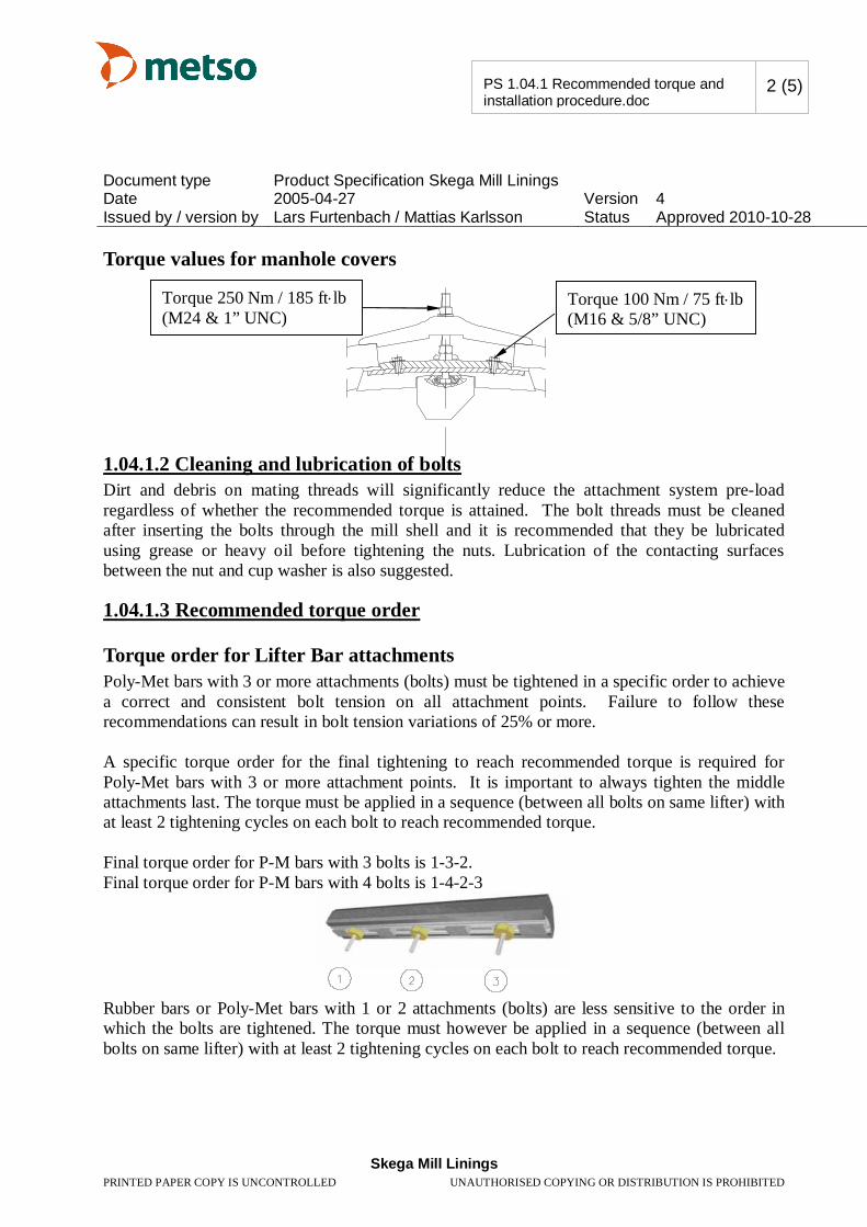
Torque values for manhole covers
1.04.1.2 Cleaning and lubrication of bolts Dirt and debris on mating threads will significantly reduce the attachment system pre-load regardless of whether the recommended torque is attained. The bolt threads must be cleaned after inserting the bolts through the mill shell and it is recommended that they be lubricated using grease or heavy oil before tightening the nuts. Lubrication of the contacting surfaces between the nut and cup washer is also suggested.
1.04.1.3 Recommended torque order
Torque order for Lifter Bar attachments Poly-Met bars with 3 or more attachments (bolts) must be tightened in a specific order to achieve a correct and consistent bolt tension on all attachment points. Failure to follow these recommendations can result in bolt tension variations of 25% or more. A specific torque order for the final tightening to reach recommended torque is required for Poly-Met bars with 3 or more attachment points. It is important to always tighten the middle attachments last. The torque must be applied in a sequence (between all bolts on same lifter) with at least 2 tightening cycles on each bolt to reach recommended torque. Final torque order for P-M bars with 3 bolts is 1-3-2. Final torque order for P-M bars with 4 bolts is 1-4-2-3
Rubber bars or Poly-Met bars with 1 or 2 attachments (bolts) are less sensitive to the order in which the bolts are tightened. The torque must however be applied in a sequence (between all bolts on same lifter) with at least 2 tightening cycles on each bolt to reach recommended torque.
Torque 250 Nm / 185 ft lb (M24 & 1” UNC)
Torque 100 Nm / 75 ft lb (M16 & 5/8” UNC)
Document type Product Specification Skega Mill Linings Date 2005-04-27 Version 4 Issued by / version by Lars Furtenbach / Mattias Karlsson Status Approved 2010-10-28
Skega Mill Linings
PRINTED PAPER COPY IS UNCONTROLLED UNAUTHORISED COPYING OR DISTRIBUTION IS PROHIBITED
PS 1.04.1 Recommended torque and installation procedure.doc
3 (5)
Torque order for manhole covers The torque must be applied in a sequence (between all pin bolts on same manhole cover) with at least 2 tightening cycles on each bolt to reach recommended torque.
Document type Product Specification Skega Mill Linings Date 2005-04-27 Version 4 Issued by / version by Lars Furtenbach / Mattias Karlsson Status Approved 2010-10-28
Skega Mill Linings
PRINTED PAPER COPY IS UNCONTROLLED UNAUTHORISED COPYING OR DISTRIBUTION IS PROHIBITED
PS 1.04.1 Recommended torque and installation procedure.doc
4 (5)
1.04.1.4 Re-torque recommendations Re-torque is required to compensate for settling & relaxation of attachment system components. In many cases it is sufficient to re-torque all nuts just prior to mill start-up, as most of the
relaxation takes place within minutes from initial tightening.
In the case of attachment systems using long bolts (as found on grate walls) additional re-torque is recommended to compensate for the self-adjustment / settling of components after the mill has been put into service. Since long bolts tend to act as torsion springs during tightening with impact tools, it is recommended that such assemblies be tightened at slow speeds and in the lubricated condition.
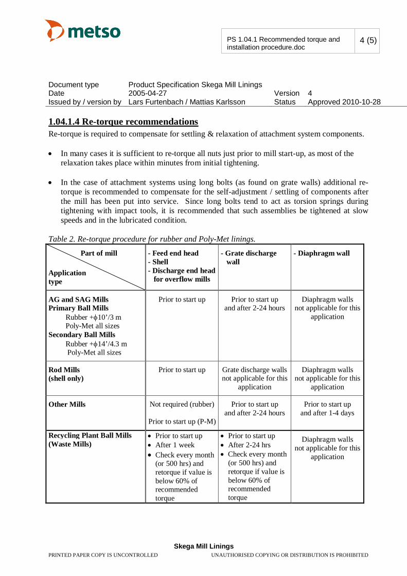
Table 2. Re-torque procedure for rubber and Poly-Met linings.
Part of mill Application type
- Feed end head - Shell - Discharge end head for overflow mills
- Grate discharge wall
- Diaphragm wall
AG and SAG Mills Primary Ball Mills Rubber + 10’/3 m Poly-Met all sizes Secondary Ball Mills Rubber + 14’/4.3 m Poly-Met all sizes
Prior to start up Prior to start up and after 2-24 hours
Diaphragm walls not applicable for this
application
Rod Mills (shell only)
Prior to start up
Grate discharge walls not applicable for this
application
Diaphragm walls not applicable for this
application
Other Mills Not required (rubber)
Prior to start up (P-M)
Prior to start up and after 2-24 hours
Prior to start up and after 1-4 days
Recycling Plant Ball Mills (Waste Mills)
Prior to start up After 1 week Check every month (or 500 hrs) and retorque if value is below 60% of recommended torque
Prior to start up After 2-24 hrs Check every month
(or 500 hrs) and retorque if value is below 60% of recommended torque
Diaphragm walls not applicable for this
application
Document type Product Specification Skega Mill Linings Date 2005-04-27 Version 4 Issued by / version by Lars Furtenbach / Mattias Karlsson Status Approved 2010-10-28
Skega Mill Linings
PRINTED PAPER COPY IS UNCONTROLLED UNAUTHORISED COPYING OR DISTRIBUTION IS PROHIBITED
PS 1.04.1 Recommended torque and installation procedure.doc
5 (5)
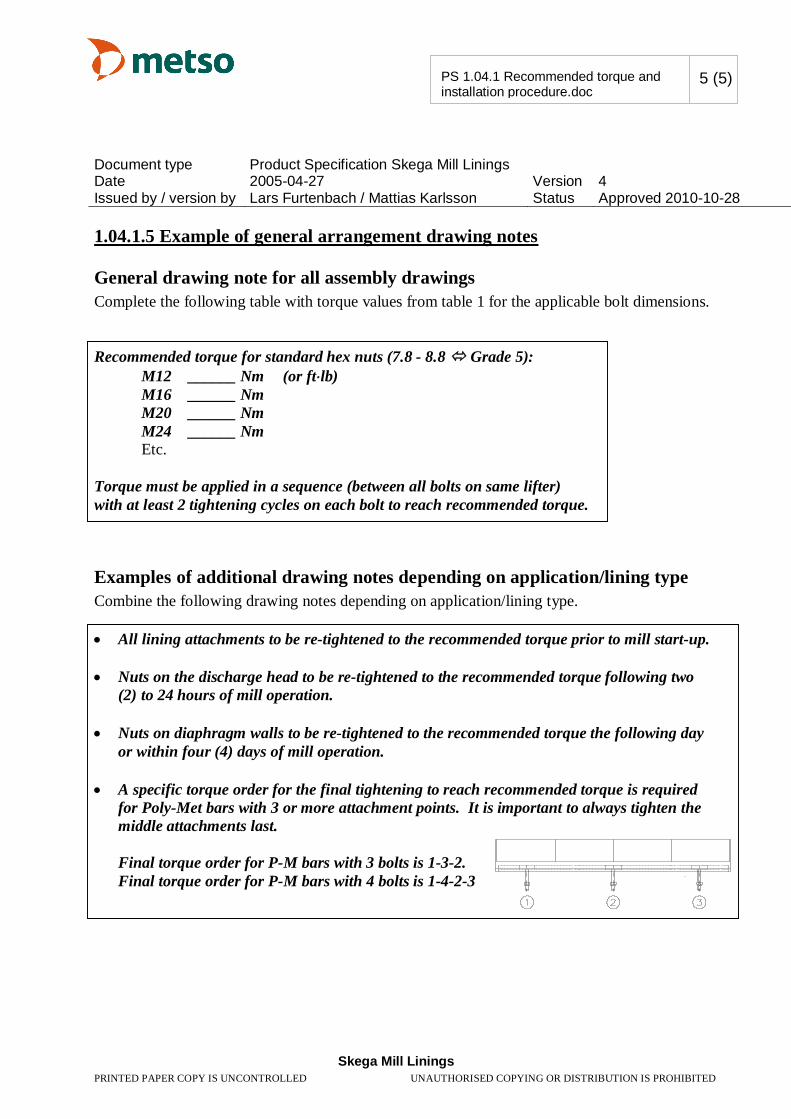
1.04.1.5 Example of general arrangement drawing notes
General drawing note for all assembly drawings Complete the following table with torque values from table 1 for the applicable bolt dimensions. Recommended torque for standard hex nuts (7.8 - 8.8 Grade 5):
M12 ______ Nm (or ft lb) M16 ______ Nm
M20 ______ Nm M24 ______ Nm
Etc. Torque must be applied in a sequence (between all bolts on same lifter) with at least 2 tightening cycles on each bolt to reach recommended torque.
Examples of additional drawing notes depending on application/lining type Combine the following drawing notes depending on application/lining type. All lining attachments to be re-tightened to the recommended torque prior to mill start-up.
Nuts on the discharge head to be re-tightened to the recommended torque following two
(2) to 24 hours of mill operation. Nuts on diaphragm walls to be re-tightened to the recommended torque the following day
or within four (4) days of mill operation. A specific torque order for the final tightening to reach recommended torque is required
for Poly-Met bars with 3 or more attachment points. It is important to always tighten the middle attachments last. Final torque order for P-M bars with 3 bolts is 1-3-2. Final torque order for P-M bars with 4 bolts is 1-4-2-3
Designation: A 193/A 193M – 08b
Standard Specification forAlloy-Steel and Stainless Steel Bolting Materials for HighTemperature or High Pressure Service and Other SpecialPurpose Applications1
This standard is issued under the fixed designation A 193/A 193M; the number immediately following the designation indicates the yearof original adoption or, in the case of revision, the year of last revision. A number in parentheses indicates the year of last reapproval.A superscript epsilon (´) indicates an editorial change since the last revision or reapproval.
This standard has been approved for use by agencies of the Department of Defense.
1. Scope*
1.1 This specification2 covers alloy and stainless steel bolt-ing material for pressure vessels, valves, flanges, and fittingsfor high temperature or high pressure service, or other specialpurpose applications. The term bolting material as used in thisspecification covers bars, bolts, screws, studs, stud bolts, andwire. Bars and wire shall be hot-wrought. The material may befurther processed by centerless grinding or by cold drawing.Austenitic stainless steel may be carbide solution treated orcarbide solution treated and strain-hardened. When strainhardened austenitic steel is ordered, the purchaser should takespecial care to ensure that Appendix X1 is thoroughly under-stood.
1.2 Several grades are covered, including ferritic steels andaustenitic stainless steels designated B5, B8, and so forth.Selection will depend upon design, service conditions, me-chanical properties, and high temperature characteristics.
1.3 The following referenced general requirements are in-dispensable for application of this specification: SpecificationA 962/A 962M.
NOTE 1—The committee formulating this specification has includedfifteen steel types that have been rather extensively used for the presentpurpose. Other compositions will be considered for inclusion by thecommittee from time to time as the need becomes apparent.
NOTE 2—For grades of alloy-steel bolting material suitable for use atthe lower range of high temperature applications, reference should bemade to Specification A 354.
NOTE 3—For grades of alloy-steel bolting material suitable for use inlow temperature applications, reference should be made to SpecificationA 320/A 320M.
1.4 Nuts for use with this bolting material are covered inSection 14.
1.5 Supplementary Requirements S1 through S14 are pro-vided for use when additional tests or inspection are desired.These shall apply only when specified in the purchase order.
1.6 This specification is expressed in both inch-pound unitsand in SI units. However, unless the order specifies theapplicable M specification designation (SI units), the materialshall be furnished to inch-pound units.
1.7 The values stated in either inch-pound units or SI unitsare to be regarded separately as standard. The values stated ineach system are not exact equivalents; therefore, each systemmust be used independently of the other. Combining valuesfrom the two systems may result in nonconformance with thespecification. Within the text, the SI units are shown inbrackets.
2. Referenced Documents
2.1 ASTM Standards: 3
A 153/A 153M Specification for Zinc Coating (Hot-Dip) onIron and Steel Hardware
A 194/A 194M Specification for Carbon and Alloy SteelNuts for Bolts for High Pressure or High TemperatureService, or Both
A 320/A 320M Specification for Alloy-Steel and StainlessSteel Bolting Materials for Low-Temperature Service
A 354 Specification for Quenched and Tempered AlloySteel Bolts, Studs, and Other Externally Threaded Fasten-ers
A 788/A 788M Specification for Steel Forgings, GeneralRequirements
A 962/A 962M Specification for Common Requirementsfor Steel Fasteners or Fastener Materials, or Both, Intendedfor Use at Any Temperature from Cryogenic to the CreepRange
B 633 Specification for Electrodeposited Coatings of Zincon Iron and Steel
1 This specification is under the jurisdiction of ASTM Committee A01 on Steel,Stainless Steel and Related Alloys and is the direct responsibility of SubcommitteeA01.22 on Steel Forgings and Wrought Fittings for Piping Applications and BoltingMaterials for Piping and Special Purpose Applications.
Current edition approved Aug. 1, 2008. Published September 2008. Originallyapproved in 1936. Last previous edition approved in 2008 as A 193/A 193M-08a.
2 For ASME Boiler and Pressure Vessel Code applications, see related Specifi-cation SA-193 in Section II of that Code.
3 For referenced ASTM standards, visit the ASTM website, www.astm.org, orcontact ASTM Customer Service at [email protected]. For Annual Book of ASTMStandards volume information, refer to the standard’s Document Summary page onthe ASTM website.
1
*A Summary of Changes section appears at the end of this standard.
Copyright © ASTM International, 100 Barr Harbor Drive, PO Box C700, West Conshohocken, PA 19428-2959, United States.
Copyright by ASTM Int'l (all rights reserved); Thu Oct 2 14:38:16 EDT 2008Downloaded/printed byUniversadad Santiago de Chile pursuant to License Agreement. No further reproductions authorized.
B 695 Specification for Coatings of Zinc MechanicallyDeposited on Iron and Steel
B 696 Specification for Coatings of Cadmium MechanicallyDeposited
B 766 Specification for Electrodeposited Coatings of Cad-mium
E 18 Test Methods for Rockwell Hardness of MetallicMaterials
E 21 Test Methods for Elevated Temperature Tension Testsof Metallic Materials
E 112 Test Methods for Determining Average Grain SizeE 139 Test Methods for Conducting Creep, Creep-Rupture,
and Stress-Rupture Tests of Metallic MaterialsE 150 Recommended Practice for Conducting Creep and
Creep-Rupture Tension Tests of Metallic Materials UnderConditions of Rapid Heating and Short Times4
E 151 Recommended Practice for Tension Tests of MetallicMaterials at Elevated Temperatures With Rapid Heatingand Conventional or Rapid Strain Rates4
E 292 Test Methods for Conducting Time-for-RuptureNotch Tension Tests of Materials
E 328 Test Methods for Stress Relaxation for Materials andStructures
E 566 Practice for Electromagnetic (Eddy-Current) Sortingof Ferrous Metals
E 709 Guide for Magnetic Particle TestingE 606 Practice for Strain-Controlled Fatigue TestingF 1940 Test Method for Process Control Verification to
Prevent Hydrogen Embrittlement in Plated or CoatedFasteners
F 1941 Specification for Electrodeposited Coatings onThreaded Fasteners (Unified Inch Screw Threads (UN/UNR))
F 2329 Specification for Zinc Coating, Hot-Dip, Require-ments for Application to Carbon and Alloy Steel Bolts,Screws, Washers, Nuts, and Special Threaded Fasteners
2.2 ANSI Standards:5
B18.2.1 Square and Hex Bolts and ScrewsB18.2.3.1M Metric Hex Cap ScrewsB18.3 Hexagon Socket and Spline Socket ScrewsB18.3.1M Metric Socket Head Cap Screws2.3 AIAG Standard:6
AIAG B-5 02.00 Primary Metals Identification Tag Appli-cation Standard
3. General Requirements and Ordering Information
3.1 The inquiry and orders shall include the following, asrequired, to describe the desired material adequately:
3.1.1 Heat-treated condition (that is, normalized and tem-pered, or quenched and tempered, for the ferritic materials, andcarbide solution treated (Class 1), carbide solution treated after
finishing (Class 1A), and carbide solution treated and strain-hardened (Classes 2, 2B and 2C), for the austenitic stainlesssteels; Classes 1B and 1C apply to the carbide solution-treatednitrogen-bearing stainless steels; Class 1D applies to materialcarbide solution treated by cooling rapidly from the rollingtemperature),
3.1.2 Description of items required (that is, bars, bolts,screws, or studs),
3.1.3 Nuts, if required by purchaser, in accordance with14.1,
3.1.4 Supplementary requirements, if any, and3.1.5 Special requirements, in accordance with 7.1.5.1,
7.2.6, 9.1, 14.1, and 15.1.3.2 Coatings—Coatings are prohibited unless specified by
the purchaser (See Supplementary Requirements S13 and S14).When coated fasteners are ordered the purchaser should takespecial care to ensure that Appendix X2 is thoroughly under-stood.
4. Common Requirements
4.1 Material and fasteners supplied to this specification shallconform to the requirements of Specification A 962/A 962M.These requirements include test methods, finish, thread dimen-sions, marking, certification, optional supplementary require-ments, and others. Failure to comply with the requirements ofSpecification A 962/A 962M constitutes nonconformance withthis specification. In case of conflict between this specificationand Specification A 962/A 962M, this specification shall pre-vail.
5. Manufacture (Process)
5.1 The steel shall be produced by any of the followingprocesses: open-hearth, basic-oxygen, electric-furnace, orvacuum-induction melting (VIM). The molten steel may bevacuum-treated prior to or during pouring of the ingot or strandcasting.
5.2 Quality—See Specification A 962/A 962M for require-ments.
6. Discard
6.1 A sufficient discard shall be made to secure freedomfrom injurious piping and undue segregation.
7. Heat Treatment
7.1 Ferritic Steels7.1.1 Ferritic steels shall be allowed to cool to a temperature
below the cooling transformation range immediately afterrolling or forging. Materials to be liquid quenched shall then beuniformly reheated to the proper temperature to refine the grain(a group thus reheated being known as a quenching charge),quenched in a liquid medium under substantially uniformconditions for each quenching charge, and tempered. Materialsto be normalized and tempered or air-quenched and temperedshall be reheated to the proper temperature to refine the grain,cooled uniformly in air to a temperature below the transfor-mation temperature range and tempered. The minimum tem-pering temperature shall be as specified in Tables 2 and 3.
4 Withdrawn.5 Available from American National Standards Institute (ANSI), 25 W. 43rd St.,
4th Floor, New York, NY 10036, http://www.ansi.org.6 Available from Automotive Industry Action Group (AIAG), 26200 Lahser Rd.,
Suite 200, Southfield, MI 48033, http://www.aiag.org.
A 193/A 193M – 08b
2Copyright by ASTM Int'l (all rights reserved); Thu Oct 2 14:38:16 EDT 2008Downloaded/printed byUniversadad Santiago de Chile pursuant to License Agreement. No further reproductions authorized.
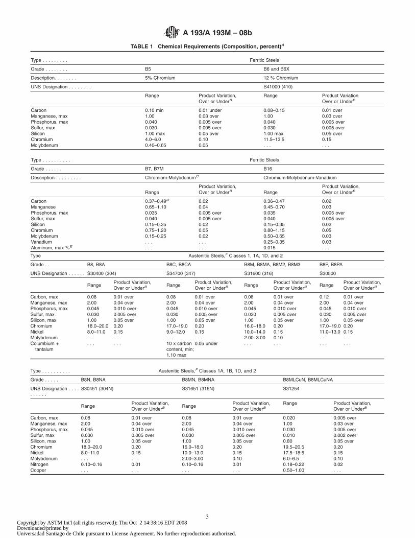
TABLE 1 Chemical Requirements (Composition, percent)A
Type . . . . . . . . . Ferritic Steels
Grade . . . . . . . . B5 B6 and B6X
Description. . . . . . . . 5% Chromium 12 % Chromium
UNS Designation . . . . . . . . S41000 (410)
Range Product Variation, Range Product VariationOver or UnderB Over or UnderB
Carbon 0.10 min 0.01 under 0.08–0.15 0.01 overManganese, max 1.00 0.03 over 1.00 0.03 overPhosphorus, max 0.040 0.005 over 0.040 0.005 overSulfur, max 0.030 0.005 over 0.030 0.005 overSilicon 1.00 max 0.05 over 1.00 max 0.05 overChromium 4.0–6.0 0.10 11.5–13.5 0.15Molybdenum 0.40–0.65 0.05 . . . . . .
Type . . . . . . . . . . Ferritic Steels
Grade . . . . . . B7, B7M B16
Description . . . . . . . . . Chromium-MolybdenumC Chromium-Molybdenum-Vanadium
Product Variation, Product Variation,Range Over or UnderB Range Over or UnderB
Carbon 0.37–0.49D 0.02 0.36–0.47 0.02Manganese 0.65–1.10 0.04 0.45–0.70 0.03Phosphorus, max 0.035 0.005 over 0.035 0.005 overSulfur, max 0.040 0.005 over 0.040 0.005 overSilicon 0.15–0.35 0.02 0.15–0.35 0.02Chromium 0.75–1.20 0.05 0.80–1.15 0.05Molybdenum 0.15–0.25 0.02 0.50–0.65 0.03Vanadium . . . . . . 0.25–0.35 0.03Aluminum, max %E . . . . . . 0.015 . . .
Type Austenitic Steels,F Classes 1, 1A, 1D, and 2
Grade . . B8, B8A B8C, B8CA B8M, B8MA, B8M2, B8M3 B8P, B8PA
UNS Designation . . . . . . S30400 (304) S34700 (347) S31600 (316) S30500
RangeProduct Variation,Over or UnderB
RangeProduct Variation,Over or UnderB
RangeProduct Variation,Over or UnderB
RangeProduct Variation,Over or UnderB
Carbon, max 0.08 0.01 over 0.08 0.01 over 0.08 0.01 over 0.12 0.01 overManganese, max 2.00 0.04 over 2.00 0.04 over 2.00 0.04 over 2.00 0.04 overPhosphorus, max 0.045 0.010 over 0.045 0.010 over 0.045 0.010 over 0.045 0.010 overSulfur, max 0.030 0.005 over 0.030 0.005 over 0.030 0.005 over 0.030 0.005 overSilicon, max 1.00 0.05 over 1.00 0.05 over 1.00 0.05 over 1.00 0.05 overChromium 18.0–20.0 0.20 17.0–19.0 0.20 16.0–18.0 0.20 17.0–19.0 0.20Nickel 8.0–11.0 0.15 9.0–12.0 0.15 10.0–14.0 0.15 11.0–13.0 0.15Molybdenum . . . . . . . . . . . . 2.00–3.00 0.10 . . . . . .Columbium + . . . . . . 10 x carbon 0.05 under . . . . . . . . . . . .
tantalum content, min;1.10 max
Type . . . . . . . . . . Austenitic Steels,F Classes 1A, 1B, 1D, and 2
Grade . . . . . B8N, B8NA B8MN, B8MNA B8MLCuN, B8MLCuNA
UNS Designation . . . .. . . . . .
S30451 (304N) S31651 (316N) S31254
RangeProduct Variation,Over or UnderB
RangeProduct Variation,Over or UnderB
Range Product Variation,Over or UnderB
Carbon, max 0.08 0.01 over 0.08 0.01 over 0.020 0.005 overManganese, max 2.00 0.04 over 2.00 0.04 over 1.00 0.03 overPhosphorus, max 0.045 0.010 over 0.045 0.010 over 0.030 0.005 overSulfur, max 0.030 0.005 over 0.030 0.005 over 0.010 0.002 overSilicon, max 1.00 0.05 over 1.00 0.05 over 0.80 0.05 overChromium 18.0–20.0 0.20 16.0–18.0 0.20 19.5–20.5 0.20Nickel 8.0–11.0 0.15 10.0–13.0 0.15 17.5–18.5 0.15Molybdenum . . . . . . 2.00–3.00 0.10 6.0–6.5 0.10Nitrogen 0.10–0.16 0.01 0.10–0.16 0.01 0.18–0.22 0.02Copper . . . . . . . . . . . . 0.50–1.00 . . .
A 193/A 193M – 08b
3Copyright by ASTM Int'l (all rights reserved); Thu Oct 2 14:38:16 EDT 2008Downloaded/printed byUniversadad Santiago de Chile pursuant to License Agreement. No further reproductions authorized.
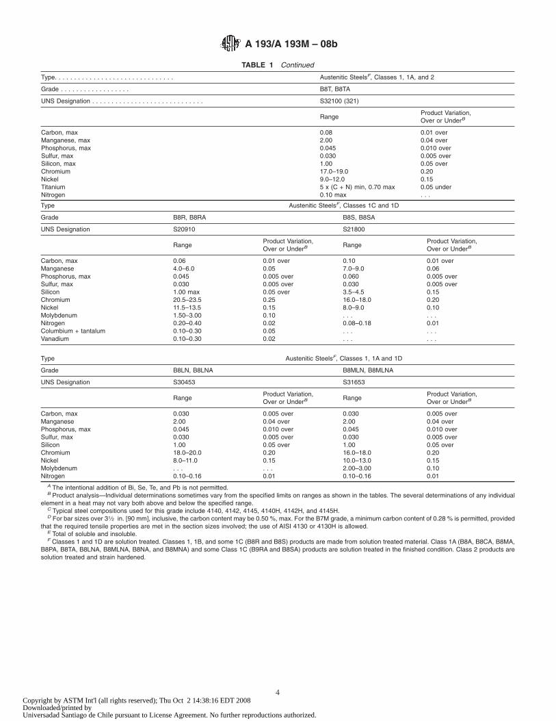
TABLE 1 Continued
Type. . . . . . . . . . . . . . . . . . . . . . . . . . . . . . . Austenitic SteelsF, Classes 1, 1A, and 2
Grade . . . . . . . . . . . . . . . . . . B8T, B8TA
UNS Designation . . . . . . . . . . . . . . . . . . . . . . . . . . . . . S32100 (321)
RangeProduct Variation,Over or UnderB
Carbon, max 0.08 0.01 overManganese, max 2.00 0.04 overPhosphorus, max 0.045 0.010 overSulfur, max 0.030 0.005 overSilicon, max 1.00 0.05 overChromium 17.0–19.0 0.20Nickel 9.0–12.0 0.15Titanium 5 x (C + N) min, 0.70 max 0.05 underNitrogen 0.10 max . . .
Type Austenitic SteelsF, Classes 1C and 1D
Grade B8R, B8RA B8S, B8SA
UNS Designation S20910 S21800
RangeProduct Variation,Over or UnderB
RangeProduct Variation,Over or UnderB
Carbon, max 0.06 0.01 over 0.10 0.01 overManganese 4.0–6.0 0.05 7.0–9.0 0.06Phosphorus, max 0.045 0.005 over 0.060 0.005 overSulfur, max 0.030 0.005 over 0.030 0.005 overSilicon 1.00 max 0.05 over 3.5–4.5 0.15Chromium 20.5–23.5 0.25 16.0–18.0 0.20Nickel 11.5–13.5 0.15 8.0–9.0 0.10Molybdenum 1.50–3.00 0.10 . . . . . .Nitrogen 0.20–0.40 0.02 0.08–0.18 0.01Columbium + tantalum 0.10–0.30 0.05 . . . . . .Vanadium 0.10–0.30 0.02 . . . . . .
Type Austenitic SteelsF, Classes 1, 1A and 1D
Grade B8LN, B8LNA B8MLN, B8MLNA
UNS Designation S30453 S31653
RangeProduct Variation,Over or UnderB
RangeProduct Variation,Over or UnderB
Carbon, max 0.030 0.005 over 0.030 0.005 overManganese 2.00 0.04 over 2.00 0.04 overPhosphorus, max 0.045 0.010 over 0.045 0.010 overSulfur, max 0.030 0.005 over 0.030 0.005 overSilicon 1.00 0.05 over 1.00 0.05 overChromium 18.0–20.0 0.20 16.0–18.0 0.20Nickel 8.0–11.0 0.15 10.0–13.0 0.15Molybdenum . . . . . . 2.00–3.00 0.10Nitrogen 0.10–0.16 0.01 0.10–0.16 0.01
A The intentional addition of Bi, Se, Te, and Pb is not permitted.B Product analysis—Individual determinations sometimes vary from the specified limits on ranges as shown in the tables. The several determinations of any individual
element in a heat may not vary both above and below the specified range.C Typical steel compositions used for this grade include 4140, 4142, 4145, 4140H, 4142H, and 4145H.D For bar sizes over 31⁄2 in. [90 mm], inclusive, the carbon content may be 0.50 %, max. For the B7M grade, a minimum carbon content of 0.28 % is permitted, provided
that the required tensile properties are met in the section sizes involved; the use of AISI 4130 or 4130H is allowed.E Total of soluble and insoluble.F Classes 1 and 1D are solution treated. Classes 1, 1B, and some 1C (B8R and B8S) products are made from solution treated material. Class 1A (B8A, B8CA, B8MA,
B8PA, B8TA, B8LNA, B8MLNA, B8NA, and B8MNA) and some Class 1C (B9RA and B8SA) products are solution treated in the finished condition. Class 2 products aresolution treated and strain hardened.
A 193/A 193M – 08b
4Copyright by ASTM Int'l (all rights reserved); Thu Oct 2 14:38:16 EDT 2008Downloaded/printed byUniversadad Santiago de Chile pursuant to License Agreement. No further reproductions authorized.
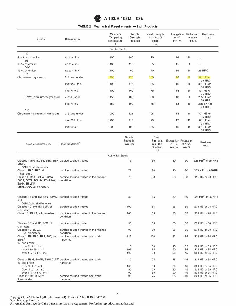
TABLE 2 Mechanical Requirements — Inch Products
Grade Diameter, in.
MinimumTempering
Temperature,°F
TensileStrength,min, ksi
Yield Strength,min, 0.2 %
offset,ksi
Elongationin 4D,min, %
Reductionof Area,min, %
Hardness,max
Ferritic Steels
B54 to 6 % chromium up to 4, incl 1100 100 80 16 50 . . .
B613 % chromium up to 4, incl 1100 110 85 15 50 . . .
B6X13 % chromium up to 4, incl 1100 90 70 16 50 26 HRC
B7Chromium-molybdenum 21⁄2 and under 1100 125 105 16 50 321 HB or
35 HRCover 21⁄2 to 4 1100 115 95 16 50 321 HB or
35 HRCover 4 to 7 1100 100 75 18 50 321 HB or
35 HRCB7MAChromium-molybdenum 4 and under 1150 100 80 18 50 235 HB or
99 HRBover 4 to 7 1150 100 75 18 50 235 BHN or
99 HRBB16
Chromium-molybdenum-vanadium 21⁄2 and under 1200 125 105 18 50 321 HB or35 HRC
over 21⁄2 to 4 1200 110 95 17 45 321 HB or35 HRC
over 4 to 8 1200 100 85 16 45 321 HB or35 HRC
Grade, Diameter, in. Heat TreatmentB
TensileStrength,min, ksi
YieldStrength,min, 0.2% offset,
ksi
Elongationin 4 D,min %
Reductionof Area,min %
Hardness,max
Austenitic Steels
Classes 1 and 1D; B8, B8M, B8P,B8LN,
carbide solution treated 75 30 30 50 223 HBC or 96 HRB
B8MLN, all diametersClass 1: B8C, B8T, all
diameterscarbide solution treated 75 30 30 50 223 HBC or 96HRB
Class 1A: B8A, B8CA, B8MA,B8PA, B8TA, B8LNA, B8MLNA,B8NA, B8MNAB8MLCuNA, all diameters
carbide solution treated in the finishedcondition
75 30 30 50 192 HB or 90 HRB
Classes 1B and 1D: B8N, B8MN,and
carbide solution treated 80 35 30 40 223 HBC or 96 HRB
B8MLCuN, all diametersClasses 1C and 1D: B8R, alldiameters
carbide solution treated 100 55 35 55 271 HB or 28 HRC
Class 1C: B8RA, all diameters carbide solution treated in the finishedcondition
100 55 35 55 271 HB or 28 HRC
Classes 1C and 1D: B8S, alldiameters
carbide solution treated 95 50 35 55 271 HB or 28 HRC
Classes 1C: B8SA, carbide solution treated in the finished 95 50 35 55 271 HB or 28 HRCall diameters condition
Class 2: B8, B8C, B8P, B8T, andB8N,D3⁄4 and under
carbide solution treated and strainhardened
125 100 12 35 321 HB or 35 HRC
over 3⁄4 to 1, incl 115 80 15 35 321 HB or 35 HRCover 1 to 11⁄4 , incl 105 65 20 35 321 HB or 35 HRCover 11⁄4 to 11⁄2 , incl 100 50 28 45 321 HB or 35 HRC
Class 2: B8M, B8MN, B8MLCuND
3⁄4 and undercarbide solution treated and strainhardened
110 95 15 45 321 HB or 35 HRC
over 3⁄4 to 1 incl 100 80 20 45 321 HB or 35 HRCOver 1 to 11⁄4 , incl 95 65 25 45 321 HB or 35 HRCover 11⁄4 to 11⁄2 , incl 90 50 30 45 321 HB or 35 HRC
Class 2B: B8, B8M2D
2 and undercarbide solution treated and strainhardened
95 75 25 40 321 HB or 35 HRC
A 193/A 193M – 08b
5Copyright by ASTM Int'l (all rights reserved); Thu Oct 2 14:38:16 EDT 2008Downloaded/printed byUniversadad Santiago de Chile pursuant to License Agreement. No further reproductions authorized.
Katherine
1100 125 105 16 50 321 HB or
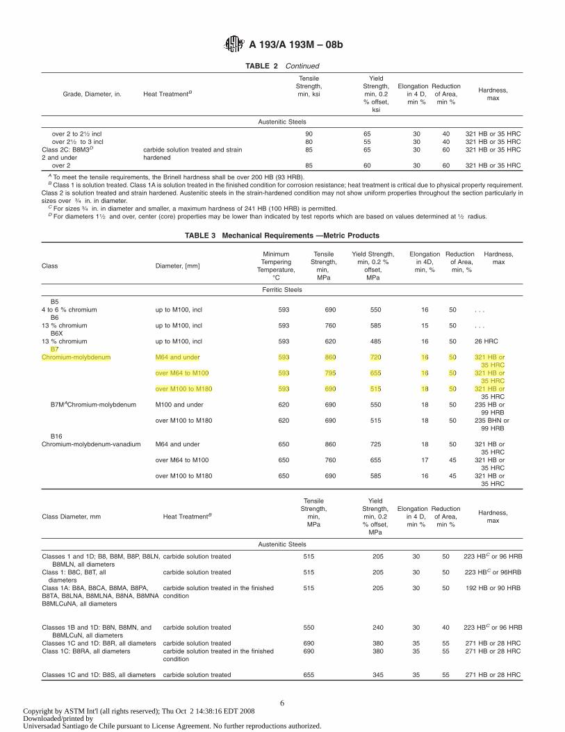
TABLE 2 Continued
Grade, Diameter, in. Heat TreatmentB
TensileStrength,min, ksi
YieldStrength,min, 0.2% offset,
ksi
Elongationin 4 D,min %
Reductionof Area,min %
Hardness,max
Austenitic Steels
over 2 to 21⁄2 incl 90 65 30 40 321 HB or 35 HRCover 21⁄2 to 3 incl 80 55 30 40 321 HB or 35 HRC
Class 2C: B8M3D
2 and undercarbide solution treated and strainhardened
85 65 30 60 321 HB or 35 HRC
over 2 85 60 30 60 321 HB or 35 HRCA To meet the tensile requirements, the Brinell hardness shall be over 200 HB (93 HRB).B Class 1 is solution treated. Class 1A is solution treated in the finished condition for corrosion resistance; heat treatment is critical due to physical property requirement.
Class 2 is solution treated and strain hardened. Austenitic steels in the strain-hardened condition may not show uniform properties throughout the section particularly insizes over 3⁄4 in. in diameter.
C For sizes 3⁄4 in. in diameter and smaller, a maximum hardness of 241 HB (100 HRB) is permitted.D For diameters 11⁄2 and over, center (core) properties may be lower than indicated by test reports which are based on values determined at 1⁄2 radius.
TABLE 3 Mechanical Requirements —Metric Products
Class Diameter, [mm]
MinimumTempering
Temperature,°C
TensileStrength,
min,MPa
Yield Strength,min, 0.2 %
offset,MPa
Elongationin 4D,min, %
Reductionof Area,min, %
Hardness,max
Ferritic Steels
B54 to 6 % chromium up to M100, incl 593 690 550 16 50 . . .
B613 % chromium up to M100, incl 593 760 585 15 50 . . .
B6X13 % chromium up to M100, incl 593 620 485 16 50 26 HRC
B7Chromium-molybdenum M64 and under 593 860 720 16 50 321 HB or
35 HRCover M64 to M100 593 795 655 16 50 321 HB or
35 HRCover M100 to M180 593 690 515 18 50 321 HB or
35 HRCB7MAChromium-molybdenum M100 and under 620 690 550 18 50 235 HB or
99 HRBover M100 to M180 620 690 515 18 50 235 BHN or
99 HRBB16
Chromium-molybdenum-vanadium M64 and under 650 860 725 18 50 321 HB or35 HRC
over M64 to M100 650 760 655 17 45 321 HB or35 HRC
over M100 to M180 650 690 585 16 45 321 HB or35 HRC
Class Diameter, mm Heat TreatmentB
TensileStrength,
min,MPa
YieldStrength,min, 0.2% offset,
MPa
Elongationin 4 D,min %
Reductionof Area,min %
Hardness,max
Austenitic Steels
Classes 1 and 1D; B8, B8M, B8P, B8LN, carbide solution treated 515 205 30 50 223 HBC or 96 HRBB8MLN, all diameters
Class 1: B8C, B8T, alldiameters
carbide solution treated 515 205 30 50 223 HBC or 96HRB
Class 1A: B8A, B8CA, B8MA, B8PA,B8TA, B8LNA, B8MLNA, B8NA, B8MNAB8MLCuNA, all diameters
carbide solution treated in the finishedcondition
515 205 30 50 192 HB or 90 HRB
Classes 1B and 1D: B8N, B8MN, and carbide solution treated 550 240 30 40 223 HBC or 96 HRBB8MLCuN, all diameters
Classes 1C and 1D: B8R, all diameters carbide solution treated 690 380 35 55 271 HB or 28 HRCClass 1C: B8RA, all diameters carbide solution treated in the finished
condition690 380 35 55 271 HB or 28 HRC
Classes 1C and 1D: B8S, all diameters carbide solution treated 655 345 35 55 271 HB or 28 HRC
A 193/A 193M – 08b
6Copyright by ASTM Int'l (all rights reserved); Thu Oct 2 14:38:16 EDT 2008Downloaded/printed byUniversadad Santiago de Chile pursuant to License Agreement. No further reproductions authorized.
Katherine
B7 Chromium-molybdenum M64 and under 593 860 720 16 50 321 HB or 35 HRC over M64 to M100 593 795 655 16 50 321 HB or 35 HRC over M100 to M180 593 690 515 18 50 321 HB or
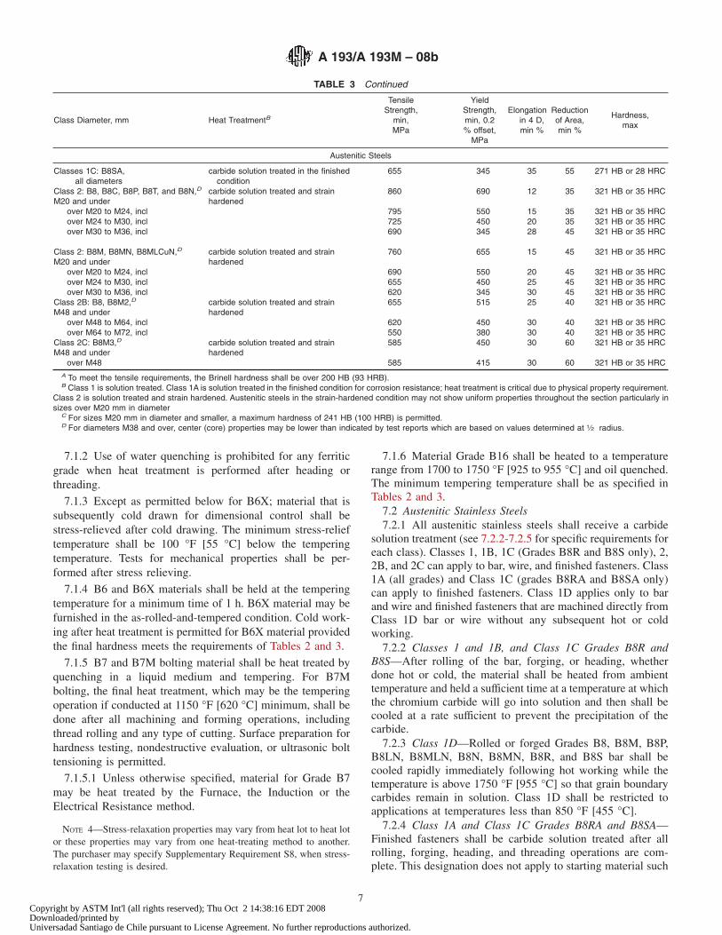
TABLE 3 Continued
Class Diameter, mm Heat TreatmentB
TensileStrength,
min,MPa
YieldStrength,min, 0.2% offset,
MPa
Elongationin 4 D,min %
Reductionof Area,min %
Hardness,max
Austenitic Steels
Classes 1C: B8SA, carbide solution treated in the finished 655 345 35 55 271 HB or 28 HRCall diameters condition
Class 2: B8, B8C, B8P, B8T, and B8N,D
M20 and undercarbide solution treated and strainhardened
860 690 12 35 321 HB or 35 HRC
over M20 to M24, incl 795 550 15 35 321 HB or 35 HRCover M24 to M30, incl 725 450 20 35 321 HB or 35 HRCover M30 to M36, incl 690 345 28 45 321 HB or 35 HRC
Class 2: B8M, B8MN, B8MLCuN,D
M20 and undercarbide solution treated and strainhardened
760 655 15 45 321 HB or 35 HRC
over M20 to M24, incl 690 550 20 45 321 HB or 35 HRCover M24 to M30, incl 655 450 25 45 321 HB or 35 HRCover M30 to M36, incl 620 345 30 45 321 HB or 35 HRC
Class 2B: B8, B8M2,D
M48 and undercarbide solution treated and strainhardened
655 515 25 40 321 HB or 35 HRC
over M48 to M64, incl 620 450 30 40 321 HB or 35 HRCover M64 to M72, incl 550 380 30 40 321 HB or 35 HRC
Class 2C: B8M3,D
M48 and undercarbide solution treated and strainhardened
585 450 30 60 321 HB or 35 HRC
over M48 585 415 30 60 321 HB or 35 HRCA To meet the tensile requirements, the Brinell hardness shall be over 200 HB (93 HRB).B Class 1 is solution treated. Class 1A is solution treated in the finished condition for corrosion resistance; heat treatment is critical due to physical property requirement.
Class 2 is solution treated and strain hardened. Austenitic steels in the strain-hardened condition may not show uniform properties throughout the section particularly insizes over M20 mm in diameter
C For sizes M20 mm in diameter and smaller, a maximum hardness of 241 HB (100 HRB) is permitted.D For diameters M38 and over, center (core) properties may be lower than indicated by test reports which are based on values determined at 1⁄2 radius.
7.1.2 Use of water quenching is prohibited for any ferriticgrade when heat treatment is performed after heading orthreading.
7.1.3 Except as permitted below for B6X; material that issubsequently cold drawn for dimensional control shall bestress-relieved after cold drawing. The minimum stress-relieftemperature shall be 100 °F [55 °C] below the temperingtemperature. Tests for mechanical properties shall be per-formed after stress relieving.
7.1.4 B6 and B6X materials shall be held at the temperingtemperature for a minimum time of 1 h. B6X material may befurnished in the as-rolled-and-tempered condition. Cold work-ing after heat treatment is permitted for B6X material providedthe final hardness meets the requirements of Tables 2 and 3.
7.1.5 B7 and B7M bolting material shall be heat treated byquenching in a liquid medium and tempering. For B7Mbolting, the final heat treatment, which may be the temperingoperation if conducted at 1150 °F [620 °C] minimum, shall bedone after all machining and forming operations, includingthread rolling and any type of cutting. Surface preparation forhardness testing, nondestructive evaluation, or ultrasonic bolttensioning is permitted.
7.1.5.1 Unless otherwise specified, material for Grade B7may be heat treated by the Furnace, the Induction or theElectrical Resistance method.
NOTE 4—Stress-relaxation properties may vary from heat lot to heat lotor these properties may vary from one heat-treating method to another.The purchaser may specify Supplementary Requirement S8, when stress-relaxation testing is desired.
7.1.6 Material Grade B16 shall be heated to a temperaturerange from 1700 to 1750 °F [925 to 955 °C] and oil quenched.The minimum tempering temperature shall be as specified inTables 2 and 3.
7.2 Austenitic Stainless Steels7.2.1 All austenitic stainless steels shall receive a carbide
solution treatment (see 7.2.2-7.2.5 for specific requirements foreach class). Classes 1, 1B, 1C (Grades B8R and B8S only), 2,2B, and 2C can apply to bar, wire, and finished fasteners. Class1A (all grades) and Class 1C (grades B8RA and B8SA only)can apply to finished fasteners. Class 1D applies only to barand wire and finished fasteners that are machined directly fromClass 1D bar or wire without any subsequent hot or coldworking.
7.2.2 Classes 1 and 1B, and Class 1C Grades B8R andB8S—After rolling of the bar, forging, or heading, whetherdone hot or cold, the material shall be heated from ambienttemperature and held a sufficient time at a temperature at whichthe chromium carbide will go into solution and then shall becooled at a rate sufficient to prevent the precipitation of thecarbide.
7.2.3 Class 1D—Rolled or forged Grades B8, B8M, B8P,B8LN, B8MLN, B8N, B8MN, B8R, and B8S bar shall becooled rapidly immediately following hot working while thetemperature is above 1750 °F [955 °C] so that grain boundarycarbides remain in solution. Class 1D shall be restricted toapplications at temperatures less than 850 °F [455 °C].
7.2.4 Class 1A and Class 1C Grades B8RA and B8SA—Finished fasteners shall be carbide solution treated after allrolling, forging, heading, and threading operations are com-plete. This designation does not apply to starting material such
A 193/A 193M – 08b
7Copyright by ASTM Int'l (all rights reserved); Thu Oct 2 14:38:16 EDT 2008Downloaded/printed byUniversadad Santiago de Chile pursuant to License Agreement. No further reproductions authorized.
as bar. Fasteners shall be heated from ambient temperature andheld a sufficient time at a temperature at which the chromiumcarbide will go into solution and then shall be cooled at a ratesufficient to prevent the precipitation of the carbide.
7.2.5 Classes 2, 2B, and 2C—Material shall be carbidesolution treated by heating from ambient temperature andholding a sufficient time at a temperature at which thechromium carbide will go into solution and then cooling at arate sufficient to prevent the precipitation of the carbide.Following this treatment the material shall then be strainhardened to achieve the required properties.
NOTE 5—Heat treatment following operations performed on a limitedportion of the product, such as heading, may result in non-uniform grainsize and mechanical properties through the section affected.
7.2.6 If a scale-free bright finish is required; this shall bespecified in the purchase order.
8. Chemical Composition
8.1 Each alloy shall conform to the chemical compositionrequirements prescribed in Table 1.
8.2 The steel shall not contain an unspecified element forthe ordered grade to the extent that the steel conforms to therequirements of another grade for which that element is aspecified element. Furthermore, elements present in concentra-tions greater than 0.75 weight/% shall be reported.
9. Heat Analysis
9.1 An analysis of each heat of steel shall be made by themanufacturer to determine the percentages of the elementsspecified in Section 8. The chemical composition thus deter-mined shall be reported to the purchaser or the purchaser’srepresentative, and shall conform to the requirements specifiedin Section 8. Should the purchaser deem it necessary to havethe transition zone of two heats sequentially cast discarded, thepurchaser shall invoke Supplementary Requirement S3 ofSpecification A 788.
10. Mechanical Properties
10.1 Tensile Properties:10.1.1 Requirements—The material as represented by the
tension specimens shall conform to the requirements pre-scribed in Tables 2 and 3 at room temperature after heattreatment. Alternatively, stainless strain hardened headed fas-teners (Class 2, 2B, and 2C) shall be tested full size after strainhardening to determine tensile strength and yield strength andshall conform to the requirements prescribed in Tables 2 and 3.Should the results of full size tests conflict with results oftension specimen tests, full size test results shall prevail.
10.1.2 Full Size Fasteners, Wedge Tensile Testing—Whenapplicable, see 13.1.3, headed fasteners shall be wedge testedfull size. The minimum full size load applied (lbf or kN) forindividual sizes shall be as follows:
W 5 Ts 3 At (1)
where:W = minimum wedge tensile load without fracture,Ts = tensile strength specified in ksi or MPa in Tables 2 and
3, and
At = stress area of the thread section, square inches orsquare milimetres, as shown in the Cone Proof LoadTables in Specification A 962/A 962M.
10.2 Hardness Requirements:10.2.1 The hardness shall conform to the requirements
prescribed in Table 2. Hardness testing shall be performed inaccordance with either Specification A 962/A 962M or withTest Methods F 606.
10.2.2 Grade B7M—The maximum hardness of the gradeshall be 235 HB or 99 HRB. The minimum hardness shall notbe less than 200 HB or 93 HRB. Conformance to this hardnessshall be ensured by testing the hardness of each stud or bolt byBrinell or Rockwell B methods in accordance with 10.2.1. Theuse of 100 % electromagnetic testing for hardness as analternative to 100 % indentation hardness testing is permissiblewhen qualified by sampling using indentation hardness testing.Each lot tested for hardness electromagnetically shall be 100 %examined in accordance with Practice E 566. Following elec-tromagnetic testing for hardness a random sample of a mini-mum of 100 pieces of each heat of steel in each lot (as definedin 13.1.1) shall be tested by indentation hardness methods. Allsamples must meet hardness requirements to permit acceptanceof the lot. If any one sample is outside of the specifiedmaximum or minimum hardness, the lot shall be rejected andeither reprocessed and resampled or tested 100 % by indenta-tion hardness methods. Product that has been 100 % tested andfound acceptable shall have a line under the grade symbol.
10.2.2.1 Surface preparation for indentation hardness test-ing shall be in accordance with Test Methods E 18. Hardnesstests shall be performed on the end of the bolt or stud. Whenthis is impractical, the hardness test shall be performedelsewhere.
11. Workmanship, Finish, and Appearance
11.1 Bolts, screws, studs, and stud bolts shall be pointed andshall have a workmanlike finish. Points shall be flat andchamfered or rounded at option of the manufacturer. Length ofpoint on studs and stud bolts shall be not less than one nor morethan two complete threads as measured from the extreme endparallel to the axis. Length of studs and stud bolts shall bemeasured from first thread to first thread.
11.2 Bolt heads shall be in accordance with the dimensionsof ANSI B18.2.1 or ANSI B18.2.3.1M. Unless otherwisespecified in the purchase order, the Heavy Hex Screws Seriesshould be used, except the maximum body diameter and radiusof fillet may be the same as for the Heavy Hex Bolt Series. Thebody diameter and head fillet radius for sizes of Heavy HexCap Screws and Bolts that are not shown in their respectivetables in ANSI B18.2.1 or ANSI B18.2.3.1M may be thatshown in the corresponding Hex Cap Screw and Bolt Tablesrespectively. Socket head fasteners shall be in accordance withANSI B18.3 or ANSI B18.3.1M.
12. Retests
12.1 If the results of the mechanical tests of any test lot donot conform to the requirements specified, the manufacturermay retreat such lot not more than twice, in which case twoadditional tension tests shall be made from such lot, all ofwhich shall conform to the requirements specified.
A 193/A 193M – 08b
8Copyright by ASTM Int'l (all rights reserved); Thu Oct 2 14:38:16 EDT 2008Downloaded/printed byUniversadad Santiago de Chile pursuant to License Agreement. No further reproductions authorized.
13. Test Specimens
13.1 Number of Tests—For heat-treated bars, one tensiontest shall be made for each diameter of each heat represented ineach tempering charge. When heat treated without interruptionin continuous furnaces, the material in a lot shall be the sameheat, same prior condition, same size, and subjected to thesame heat treatment. Not fewer than two tension tests arerequired for each lot containing 20 000 lb [9000 kg] or less.Every additional 10 000 lb [4500 kg] or fraction thereofrequires one additional test.
13.1.1 For studs, bolts, screws, and so forth, one tension testshall be made for each diameter of each heat involved in thelot. Each lot shall consist of the following:
Diameter, in. [mm] Lot Size11⁄8 [30] and under 1500 lb [780 kg] or fraction thereofOver 11⁄8 [30] to 13⁄4 [42], incl 4500 lb [2000 kg] or fraction thereofOver 13⁄4 [42] to 21⁄2 [64], incl 6000 lb [2700 kg] or fraction thereofOver 21⁄2 [64] 100 pieces or fraction thereof
13.1.2 Tension tests are not required to be made on bolts,screws, studs, or stud bolts that are fabricated from heat-treatedbars furnished in accordance with the requirements of thisspecification and tested in accordance with 13.1, provided theyare not given a subsequent heat treatment.
13.1.3 Full Size Specimens, Headed Fasteners—Headedfasteners 11⁄2 in. in body diameter and smaller, with bodylength three times the diameter or longer, and that are producedby upsetting or forging (hot or cold) shall be subjected to fullsize testing in accordance with 10.1.2. This testing shall be inaddition to tensile testing as specified in 10.1.1. The lot sizeshall be as shown in 13.1.1. Failure shall occur in the body orthreaded section with no failure, or indications of failure, suchas cracks, at the junction of the head and shank.
14. Nuts
14.1 Bolts, studs, and stud bolts shall be furnished withnuts, when specified in the purchase order. Nuts shall conformto Specification A 194/A 194M.
15. Rejection and Rehearing
15.1 Unless otherwise specified in the basis of purchase, anyrejection based on product analysis shall be reported to themanufacturer within 30 days from the receipt of samples by thepurchaser.
15.2 Material that shows defects subsequent to its accep-tance at the place of manufacture shall be rejected, and themanufacturer shall be notified.
15.3 Product Analysis—Samples that represent rejected ma-terial shall be preserved for two weeks from the date of the testreport. In the case of dissatisfaction with the results of the test,the manufacturer may make claim for a rehearing within thattime.
16. Certification
16.1 The producer of the raw material or finished fastenersshall furnish a certification to the purchaser or his representa-
tive showing the results of the chemical analysis, macroetchexamination (Carbon and Alloy Steels Only), and mechanicaltests, and state the method of heat treatment employed.
16.2 Certification shall also include at least the following:16.2.1 A statement that the material or the fasteners, or both,
were manufactured, sampled, tested, and inspected in accor-dance with the specification and any supplementary require-ments or other requirements designated in the purchase orderor contract and was found to meet those requirements.
16.2.2 The specification number, year date, and identifica-tion symbol.
17. Product Marking
17.1 The marking symbol and manufacturer’s identificationsymbol shall be applied to one end of studs 3⁄8 in. [10 mm] indiameter and larger and to the heads of bolts 1⁄4 in. [6 mm] indiameter and larger. (If the available area is inadequate, themarking symbol may be placed on one end with the manufac-turer’s identification symbol placed on the other end.) Themarking symbol shall be as shown in Table 4 and Table 5.Grade B7M, which has been 100 % evaluated in conformancewith the specification, shall have a line under the markingsymbol to distinguish it from B7M produced to previousspecification revisions not requiring 100 % hardness testing.
17.2 For bolting materials, including threaded bars, fur-nished bundled and tagged or boxed, the tags and boxes shallcarry the marking symbol for the material identification and themanufacturer’s identification symbol or name.
17.3 For purposes of product marking, the manufacturer isconsidered the organization that certifies the fastener wasmanufactured, sampled, tested, and inspected in accordancewith the specification and the results have been determined tomeet the requirements of this specification.
17.4 Bar Coding—In addition to the requirements in 17.1,17.2, and 17.3, bar coding is acceptable as a supplementaryidentification method. Bar coding should be consistent withAIAG Standard B-5 02.00. If used on small items, the bar codemay be applied to the box or a substantially applied tag.
18. Keywords
18.1 hardness; heat treatment
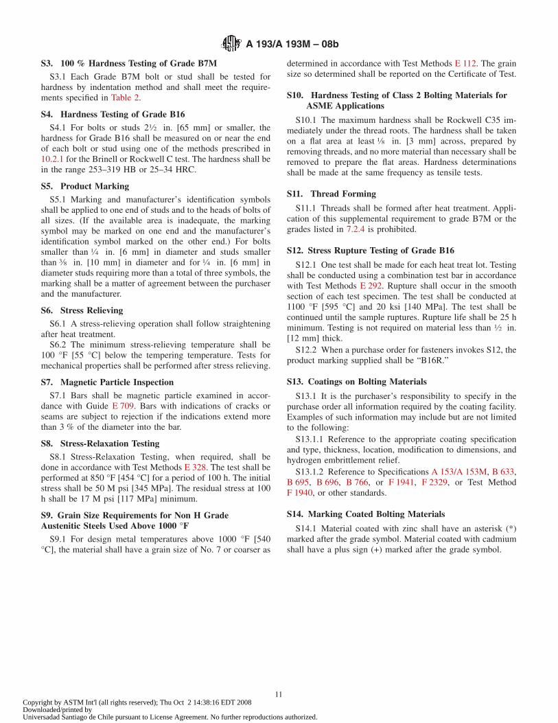
TABLE 4 Marking of Ferritic Steels
Grade Marking Symbol
B5 B5B6 B6B6X B6XB7 B7B7MA B7M
B7MB16 B16B16 +
Supplement S12B16R
A For explanations, see 10.2.2 and 17.1.
A 193/A 193M – 08b
9Copyright by ASTM Int'l (all rights reserved); Thu Oct 2 14:38:16 EDT 2008Downloaded/printed byUniversadad Santiago de Chile pursuant to License Agreement. No further reproductions authorized.
SUPPLEMENTARY REQUIREMENTS
These requirements shall not apply unless specified in the order and in the Ordering Information,in which event the specified tests shall be made before shipment of the product.
S1. High Temperature Tests
S1.1 Tests to determine high temperature properties shall bemade in accordance with Test Methods E 21, E 139, and E 292,and Practices E 150 and E 151.
S2. Charpy Impact Tests
S2.1 Charpy impact tests based on the requirements ofSpecification A 320/A 320M, Sections 6 and 7, shall be made
as agreed between the manufacturer and the purchaser. Whentesting temperatures are as low as those specified in Specifi-cation A 320/A 320M, bolting should be ordered to that speci-fication in preference to this specification.
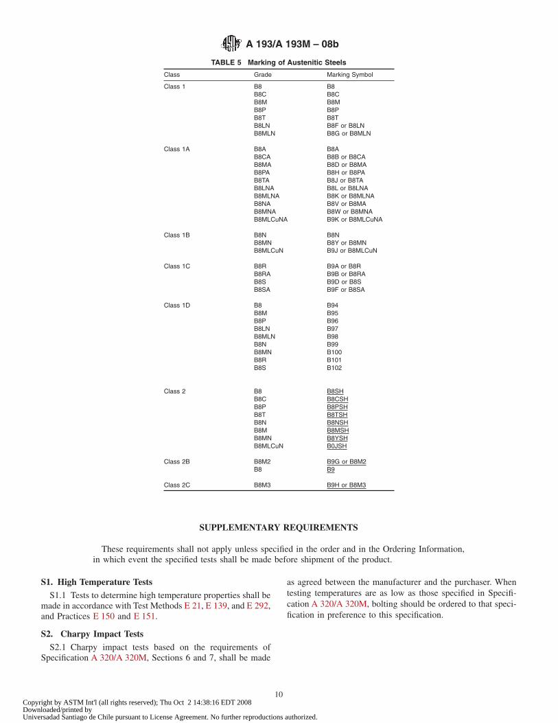
TABLE 5 Marking of Austenitic Steels
Class Grade Marking Symbol
Class 1 B8 B8B8C B8CB8M B8MB8P B8PB8T B8TB8LN B8F or B8LNB8MLN B8G or B8MLN
Class 1A B8A B8AB8CA B8B or B8CAB8MA B8D or B8MAB8PA B8H or B8PAB8TA B8J or B8TAB8LNA B8L or B8LNAB8MLNA B8K or B8MLNAB8NA B8V or B8MAB8MNA B8W or B8MNAB8MLCuNA B9K or B8MLCuNA
Class 1B B8NB8MNB8MLCuN
B8NB8Y or B8MNB9J or B8MLCuN
Class 1C B8R B9A or B8RB8RA B9B or B8RAB8S B9D or B8SB8SA B9F or B8SA
Class 1D B8 B94B8M B95B8P B96B8LN B97B8MLN B98B8N B99B8MN B100B8R B101B8S B102
Class 2 B8 B8SHB8C B8CSHB8P B8PSHB8T B8TSHB8N B8NSHB8M B8MSHB8MN B8YSHB8MLCuN B0JSH
Class 2B B8M2B8
B9G or B8M2B9
Class 2C B8M3 B9H or B8M3
A 193/A 193M – 08b
10Copyright by ASTM Int'l (all rights reserved); Thu Oct 2 14:38:16 EDT 2008Downloaded/printed byUniversadad Santiago de Chile pursuant to License Agreement. No further reproductions authorized.
S3. 100 % Hardness Testing of Grade B7M
S3.1 Each Grade B7M bolt or stud shall be tested forhardness by indentation method and shall meet the require-ments specified in Table 2.
S4. Hardness Testing of Grade B16
S4.1 For bolts or studs 21⁄2 in. [65 mm] or smaller, thehardness for Grade B16 shall be measured on or near the endof each bolt or stud using one of the methods prescribed in10.2.1 for the Brinell or Rockwell C test. The hardness shall bein the range 253–319 HB or 25–34 HRC.
S5. Product Marking
S5.1 Marking and manufacturer’s identification symbolsshall be applied to one end of studs and to the heads of bolts ofall sizes. (If the available area is inadequate, the markingsymbol may be marked on one end and the manufacturer’sidentification symbol marked on the other end.) For boltssmaller than 1⁄4 in. [6 mm] in diameter and studs smallerthan 3⁄8 in. [10 mm] in diameter and for 1⁄4 in. [6 mm] indiameter studs requiring more than a total of three symbols, themarking shall be a matter of agreement between the purchaserand the manufacturer.
S6. Stress Relieving
S6.1 A stress-relieving operation shall follow straighteningafter heat treatment.
S6.2 The minimum stress-relieving temperature shall be100 °F [55 °C] below the tempering temperature. Tests formechanical properties shall be performed after stress relieving.
S7. Magnetic Particle Inspection
S7.1 Bars shall be magnetic particle examined in accor-dance with Guide E 709. Bars with indications of cracks orseams are subject to rejection if the indications extend morethan 3 % of the diameter into the bar.
S8. Stress-Relaxation Testing
S8.1 Stress-Relaxation Testing, when required, shall bedone in accordance with Test Methods E 328. The test shall beperformed at 850 °F [454 °C] for a period of 100 h. The initialstress shall be 50 M psi [345 MPa]. The residual stress at 100h shall be 17 M psi [117 MPa] minimum.
S9. Grain Size Requirements for Non H GradeAustenitic Steels Used Above 1000 °F
S9.1 For design metal temperatures above 1000 °F [540°C], the material shall have a grain size of No. 7 or coarser as
determined in accordance with Test Methods E 112. The grainsize so determined shall be reported on the Certificate of Test.
S10. Hardness Testing of Class 2 Bolting Materials forASME Applications
S10.1 The maximum hardness shall be Rockwell C35 im-mediately under the thread roots. The hardness shall be takenon a flat area at least 1⁄8 in. [3 mm] across, prepared byremoving threads, and no more material than necessary shall beremoved to prepare the flat areas. Hardness determinationsshall be made at the same frequency as tensile tests.
S11. Thread Forming
S11.1 Threads shall be formed after heat treatment. Appli-cation of this supplemental requirement to grade B7M or thegrades listed in 7.2.4 is prohibited.
S12. Stress Rupture Testing of Grade B16
S12.1 One test shall be made for each heat treat lot. Testingshall be conducted using a combination test bar in accordancewith Test Methods E 292. Rupture shall occur in the smoothsection of each test specimen. The test shall be conducted at1100 °F [595 °C] and 20 ksi [140 MPa]. The test shall becontinued until the sample ruptures. Rupture life shall be 25 hminimum. Testing is not required on material less than 1⁄2 in.[12 mm] thick.
S12.2 When a purchase order for fasteners invokes S12, theproduct marking supplied shall be “B16R.”
S13. Coatings on Bolting Materials
S13.1 It is the purchaser’s responsibility to specify in thepurchase order all information required by the coating facility.Examples of such information may include but are not limitedto the following:
S13.1.1 Reference to the appropriate coating specificationand type, thickness, location, modification to dimensions, andhydrogen embrittlement relief.
S13.1.2 Reference to Specifications A 153/A 153M, B 633,B 695, B 696, B 766, or F 1941, F 2329, or Test MethodF 1940, or other standards.
S14. Marking Coated Bolting Materials
S14.1 Material coated with zinc shall have an asterisk (*)marked after the grade symbol. Material coated with cadmiumshall have a plus sign (+) marked after the grade symbol.
A 193/A 193M – 08b
11Copyright by ASTM Int'l (all rights reserved); Thu Oct 2 14:38:16 EDT 2008Downloaded/printed byUniversadad Santiago de Chile pursuant to License Agreement. No further reproductions authorized.
APPENDIXES
(Nonmandatory Information)
X1. STRAIN HARDENING OF AUSTENITIC STEELS
X1.1 Strain hardening is the increase in strength andhardness that results from plastic deformation below therecrystallization temperature (cold work). This effect is pro-duced in austenitic stainless steels by reducing oversized barsor wire to the desired final size by cold drawing or otherprocess. The degree of strain hardening achievable in any alloyis limited by its strain hardening characteristics. In addition, theamount of strain hardening that can be produced is furtherlimited by the variables of the process, such as the total amountof cross-section reduction, die angle, and bar size. In largediameter bars, for example, plastic deformation will occurprincipally in the outer regions of the bar so that the increasedstrength and hardness due to strain hardening is achievedpredominantly near the surface of the bar. That is, the smaller
the bar, the greater the penetration of strain hardening.
X1.2 Thus, the mechanical properties of a given strainhardened fastener are dependent not just on the alloy, but alsoon the size of bar from which it is machined. The minimum barsize that can be used, however, is established by the configu-ration of the fastener so that the configuration can affect thestrength of the fastener.
X1.3 For example, a stud of a particular alloy and size maybe machined from a smaller diameter bar than a bolt of thesame alloy and size because a larger diameter bar is required toaccommodate the head of the bolt. The stud, therefore, is likelyto be stronger than the same size bolt in a given alloy.
X2. COATINGS AND APPLICATION LIMITS
X2.1 Use of coated fasteners at temperatures above ap-proximately one-half the melting point (Fahrenheit or Celsius)of the coating is not recommended unless consideration isgiven to the potential for liquid and solid metal embrittlement,or both. The melting point of elemental zinc is approximately
780 °F [415 °C]. Therefore, application of zinc-coated fasten-ers should be limited to temperatures less than 390 °F [210 °C].The melting point of cadmium is approximately 600 °F [320°C]. Therefore, application of cadmium-coated fastenersshould be limited to temperatures less than 300 °F [160 °C].
SUMMARY OF CHANGES
Committee A01 has identified the location of selected changes to this specification since the last issue,A 193/A 193M – 08a, that may impact the use of this specification. (Approved August 1, 2008).
(1) Added new paragraph 1.3 and renumbered subsequentparagraphs.
(2) Added reference to Specifications B 633 and F 2329 toS13.1.2.
Committee A01 has identified the location of selected changes to this specification since the last issue,A 193/A 193M – 08, that may impact the use of this specification. (Approved May 1, 2008).
(1) Reorganized and edited 7.1 to clarify and separate ferriticgrades from austenitic grades. Clarified use of water quenchingfor threaded ferritic grades and intent relative to stress relief ofcold worked B6X. Added reference in Section 10 to Table 3and Specification A 962/A 962M for wedge tensile testing ofmetric product.
Committee A01 has identified the location of selected changes to this specification since the last issue,A 193/A 193M – 07, that may impact the use of this specification. (Approved April 1, 2008).
(1) Added new Supplementary Requirement S14. (2) Added Nitrogen for Grades B8T and B8TA in Table 1.
A 193/A 193M – 08b
12Copyright by ASTM Int'l (all rights reserved); Thu Oct 2 14:38:16 EDT 2008Downloaded/printed byUniversadad Santiago de Chile pursuant to License Agreement. No further reproductions authorized.
Committee A01 has identified the location of selected changes to this specification since the last issue,A 193/A 193M – 06a, that may impact the use of this specification. (Approved March 1, 2007).
(1) Deleted the space between the S and the numbers in theUNS designations in Table 1.
(2) Added permissible product variations for B8MLCuN andB8MLCuNA in Table 1.
(3) Added the requirement to report nitrogen for S32100 andchanged the order of the elements in Table 1 for this grade tobe consistent with the other stainless grades.
(4) Corrected the metric yield strength for B16 M100 to M180in Table 3.
(5) Corrected the metric conversion in S12.
(6) Added reference to Test Method F 1940 and SpecificationF 1941, and dropped reference to Specification B 633, in S13.
ASTM International takes no position respecting the validity of any patent rights asserted in connection with any item mentionedin this standard. Users of this standard are expressly advised that determination of the validity of any such patent rights, and the riskof infringement of such rights, are entirely their own responsibility.
This standard is subject to revision at any time by the responsible technical committee and must be reviewed every five years andif not revised, either reapproved or withdrawn. Your comments are invited either for revision of this standard or for additional standardsand should be addressed to ASTM International Headquarters. Your comments will receive careful consideration at a meeting of theresponsible technical committee, which you may attend. If you feel that your comments have not received a fair hearing you shouldmake your views known to the ASTM Committee on Standards, at the address shown below.
This standard is copyrighted by ASTM International, 100 Barr Harbor Drive, PO Box C700, West Conshohocken, PA 19428-2959,United States. Individual reprints (single or multiple copies) of this standard may be obtained by contacting ASTM at the aboveaddress or at 610-832-9585 (phone), 610-832-9555 (fax), or [email protected] (e-mail); or through the ASTM website(www.astm.org).
A 193/A 193M – 08b
13Copyright by ASTM Int'l (all rights reserved); Thu Oct 2 14:38:16 EDT 2008Downloaded/printed byUniversadad Santiago de Chile pursuant to License Agreement. No further reproductions authorized.
Designation: A 194/A 194M – 08b Endorsed byManufacturers Standardization Society
of the Valve and Fittings IndustryUsed in USNRC-RDT Standards
Standard Specification forCarbon and Alloy Steel Nuts for Bolts for High Pressure orHigh Temperature Service, or Both1
This standard is issued under the fixed designation A 194/A 194M; the number immediately following the designation indicates the yearof original adoption or, in the case of revision, the year of last revision. A number in parentheses indicates the year of last reapproval.A superscript epsilon (´) indicates an editorial change since the last revision or reapproval.
This standard has been approved for use by agencies of the Department of Defense.
1. Scope*
1.1 This specification2 covers a variety of carbon, alloy, andmartensitic stainless steel nuts in the size range 1⁄4 through 4in. and metric M6 through M100 nominal. It also coversaustenitic stainless steel nuts in the size range 1⁄4 in. and M6nominal and above. These nuts are intended for high-pressureor high-temperature service, or both. Grade substitutions with-out the purchaser’s permission are not allowed.
1.2 Bars from which the nuts are made shall be hot-wrought.The material may be further processed by centerless grindingor by cold drawing. Austenitic stainless steel may be solutionannealed or annealed and strain-hardened. When annealed andstrain hardened austenitic stainless steel is ordered in accor-dance with Supplementary Requirement S1, the purchasershould take special care to ensure that 8.2.2, SupplementaryRequirement S1, and Appendix X1 are thoroughly understood.
1.3 Supplementary requirements (S1 through S8) of anoptional nature are provided. These shall apply only whenspecified in the inquiry, contract, and order.
1.4 This specification is expressed in both inch-pound unitsand in SI units. However, unless the order specifies theapplicable“ M” specification designation (SI units), the mate-rial shall be furnished to inch-pound units.
1.5 The values stated in either inch-pound units or SI unitsare to be regarded separately as standard. The values stated ineach system are not exact equivalents; therefore, each systemmust be used independently of the other. Combining valuesfrom the two systems may result in nonconformance with thespecification. Within the text, the SI units are shown inbrackets.
2. Referenced Documents
2.1 ASTM Standards: 3
A 153/A 153M Specification for Zinc Coating (Hot-Dip) onIron and Steel Hardware
A 276 Specification for Stainless Steel Bars and ShapesA 320/A 320M Specification for Alloy-Steel and Stainless
Steel Bolting Materials for Low-Temperature ServiceA 962/A 962M Specification for Common Requirements
for Steel Fasteners or Fastener Materials, or Both, Intendedfor Use at Any Temperature from Cryogenic to the CreepRange
B 633 Specification for Electrodeposited Coatings of Zincon Iron and Steel
B 695 Specification for Coatings of Zinc MechanicallyDeposited on Iron and Steel
B 696 Specification for Coatings of Cadmium MechanicallyDeposited
B 766 Specification for Electrodeposited Coatings of Cad-mium
E 112 Test Methods for Determining Average Grain SizeF 1940 Test Method for Process Control Verification to
Prevent Hydrogen Embrittlement in Plated or CoatedFasteners
F 1941 Specification for Electrodeposited Coatings onThreaded Fasteners (Unified Inch Screw Threads (UN/UNR))
F 2329 Specification for Zinc Coating, Hot-Dip, Require-ments for Application to Carbon and Alloy Steel Bolts,Screws, Washers, Nuts, and Special Threaded Fasteners
2.2 American National Standards:4
B 1.1 Unified Screw ThreadsB 1.2 Gages and Gaging for Unified Inch Screw Threads
1 This specification is under the jurisdiction of ASTM Committee A01 on Steel,Stainless Steel and Related Alloys and is the direct responsibility of SubcommitteeA01.22 on Steel Forgings and Wrought Fittings for Piping Applications and BoltingMaterials for Piping and Special Purpose Applications.
Current edition approved Aug. 1, 2008. Published September 2008. Originallyapproved in 1936. Last previous edition approved in 2008 as A 194/A 194M–08a.
2 For ASME Boiler and Pressure Vessel Code applications see related Specifi-cation SA-194 in Section II of that code.
3 For referenced ASTM standards, visit the ASTM website, www.astm.org, orcontact ASTM Customer Service at [email protected]. For Annual Book of ASTMStandards volume information, refer to the standard’s Document Summary page onthe ASTM website.
4 Available from American National Standards Institute (ANSI), 25 W. 43rd St.,4th Floor, New York, NY 10036, http://www.ansi.org.
1
*A Summary of Changes section appears at the end of this standard.
Copyright © ASTM International, 100 Barr Harbor Drive, PO Box C700, West Conshohocken, PA 19428-2959, United States.
Copyright by ASTM Int'l (all rights reserved); Tue Oct 7 21:36:37 EDT 2008Downloaded/printed byUniversadad Santiago de Chile pursuant to License Agreement. No further reproductions authorized.
B 1.13M Metric Screw ThreadsB 18.2.2 Square and Hex NutsB 18.2.4.6M Metric Heavy Hex Nuts
3. Terminology
3.1 Definitions of Terms Specific to This Standard:3.1.1 Austenitic Grades—All grades with a prefix of “8” or
“9”.3.1.2 Ferritic Grades—Grades 1, 2, 2H, 2HM, 3, 4, 6, 6F, 7,
7M, and 16.3.1.3 Lot—Unless otherwise specified (see Discussion be-
low), a lot is the quantity of nuts of a single nominal size andgrade produced by the same manufacturing process.
3.1.3.1 Discussion—When Supplementary Requirement S5is invoked on the purchase order, the following definitions of alot shall apply:
3.1.3.2 For Grade 8 Nuts—The quantity of all the nuts of asingle nominal diameter and grade made from the same heat ofsteel and made by the same manufacturing process.
3.1.3.3 For All Other Grade Nuts— (see 8.2 and 8.1.2.1)—All the nuts of a single nominal diameter and grade made fromthe same heat number and heat treated in the same batch ifbatch-type heat treating equipment is used or heat treated in thesame continuous run of not more than 8 h under the sameconditions if continuous-type heat treating equipment is used.
3.1.4 Type3.1.4.1 For Grade 8 Nuts—Variations within the grade
designated by a letter and differentiated by chemistry and bymanufacturing process.
3.1.4.2 For Grade 6 Nuts—Variations within the gradedesignated by the letter F as differentiated by chemical addi-tions made for machineability.
3.1.5 Series—The dimensional relationship and geometryof the nuts as described in ANSI B 18.2.2 or B 18.2.4.6M.
4. Ordering Information
4.1 The inquiry and order for material under this specifica-tion shall include the following as required to describe thematerial adequately:
4.1.1 Specification designation, year date, and grade, issuedate and revision letter,
4.1.2 Quantity, number of pieces,4.1.3 Dimensions (see Section 9),4.1.4 Options in accordance with 8.2.2.1, 9.1, 9.2, 10.3, and
12, and4.1.5 Supplementary Requirements, if any.4.2 Coatings—Coatings are prohibited unless specified by
the purchaser (see Supplementary Requirements S7 and S8).When coated nuts are ordered, the purchaser should takespecial care to ensure that Appendix X2 is thoroughly under-stood.
4.3 See Supplementary Requirement S3 for nuts to be usedin low temperature applications (Specification A 320/A 320M).
4.4 Proof Load Testing—See Supplementary RequirementS9 for proof load testing of nuts manufactured to dimensionsand configurations other than those covered in Tables 3 and 4.
5. Common Requirements
5.1 Material and fasteners supplied to this specification shallconform to the requirements of Specification A 962/A 962M.These requirements include test methods, finish, thread dimen-sions, marking, certification, optional supplementary require-ments, and others. Failure to comply with the requirements ofSpecification A 962/A 962M constitutes nonconformance withthis specification. In case of conflict between the requirementsof this specification and Specification A 962/A 962M, thisspecification shall prevail.
6. Manufacture (Process)
6.1 Stainless steels for all types of Grade 6 and 8 nuts shallbe made by one of the following processes:
6.1.1 Electric-furnace (with separate degassing and refiningoptional),
6.1.2 Vacuum induction furnace, or6.1.3 Either of the above followed by electroslag remelting,
or consumable-arc remelting.6.2 The steel producer shall exercise adequate control to
eliminate excessive unhomogeneity, nonmetallics, pipe, poros-ity, and other defects.
6.3 Grades 1 and 2 nuts shall be hot or cold forged, or shallbe machined from hot-forged, hot-rolled, or cold-drawn bars.
6.3.1 All Grade 1 and 2 nuts made by cold forging or bymachining from cold-drawn bars shall be stress-relief annealedat a temperature of at least 1000 °F [538 °C].
6.3.2 Grade 1 and 2 nuts made by hot forging or bymachining from hot-forged or hot-rolled bars need not be givenany stress relief annealing treatment.
6.4 Grades 2H, 2HM, 3, 4, 6, 6F, 7, 7M, and 16 nuts shallbe hot- or cold-forged or shall be machined from hot-forged,hot-rolled, or cold-drawn bars and shall be heat treated to meetthe required mechanical properties. These grades shall bereheated above the critical range of the steel, quenched in asuitable medium, and then tempered at a temperature not lessthan the following:
GradeMinimum Tempering Temperature, °F
[°C]2H 850 [455]2HM 1150 [620]3 1050 [565]4 1100 [595]6 and 6F 1100 [595]7 1100 [595]7M 1150 [620]16 1200 [650]
Nuts machined from bar heat treated in accordance with thisspecification need not be reheat-treated. For Grade 2HM and7M nuts, a final stress relief shall be done at or above theminimum tempering temperature after all forming, machining,and tapping operations. This final stress relief may be thetempering operation.
6.4.1 Grade 6 and 6F nuts shall be tempered for a minimumof 1 h at the temperature.
6.5 Grades 8, 8C, 8M, 8T, 8F, 8P, 8N, 8MN, 8R, 8S, 8LN,8MLN, 8MLCuN, and 9C nuts shall be hot or cold forged, orshall be machined from hot-forged, hot-rolled or cold-drawnbars.
A 194/A 194M – 08b
2Copyright by ASTM Int'l (all rights reserved); Tue Oct 7 21:36:37 EDT 2008Downloaded/printed byUniversadad Santiago de Chile pursuant to License Agreement. No further reproductions authorized.
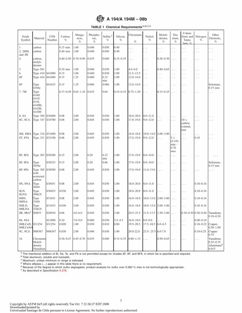
TABLE 1 Chemical RequirementsA,B,C,D
GradeSymbol
MaterialUNS
NumberCarbon,
%
Manga-nese,
%
Phospho-rus,%
Sulfur,E
%Silicon,
%
Chromium,
%
Nickel,%
Molyb-denum,
%
Tita-nium,
%
Colum-bium and
Tanta-lum, %
Nitrogen,%
OtherElements,
%
1 carbon 0.15 min 1.00 0.040 0.050 0.40 . . . . . . . . . . . . . . . . . . . . .2, 2HM,and 2H
carbon 0.40 min 1.00 0.040 0.050 0.40 . . . . . . . . . . . . . . . . . . . . .
4 carbon,molyb-denum
0.40–0.50 0.70–0.90 0.035 0.040 0.15–0.35 . . . . . . 0.20–0.30 . . . . . . . . . . . .
3 Type 501 0.10 min 1.00 0.040 0.030 1.00 4.0–6.0 . . . 0.40–0.65 . . . . . . . . . . . .6 Type 410 S41000 0.15 1.00 0.040 0.030 1.00 11.5–13.5 . . . . . . . . . . . . . . . . . .6F Type 416 S41600 0.15 1.25 0.060 0.15
min1.00 12.0–14.0 . . . . . . . . . . . . . . . . . .
6F Type416Se
S41623 0.15 1.25 0.060 0.060 1.00 12.0–14.0 . . . . . . . . . . . . Selenium,0.15 min
7, 7M Type4140/4142/4145,4140H,4142H,4145H
0.37–0.49 0.65–1.10 0.035 0.04 0.15–0.35 0.75–1.20 . . . 0.15–0.25 . . . . . . . . . . . .
8, 8A Type 304 S30400 0.08 2.00 0.045 0.030 1.00 18.0–20.0 8.0–11.0 . . . . . . . . . . . . . . .8C, 8CA Type 347 S34700 0.08 2.00 0.045 0.030 1.00 17.0–19.0 9.0–12.0 . . . . . . 10 x
carboncontent,min
. . . . . .
8M, 8MA Type 316 S31600 0.08 2.00 0.045 0.030 1.00 16.0–18.0 10.0–14.0 2.00–3.00 . . . . . . . . . . . .8T, 8TA Type 321 S32100 0.08 2.00 0.045 0.030 1.00 17.0–19.0 9.0–12.0 . . . 5 x
(C+N)min -0.70max
. . . 0.10 . . .
8F, 8FA Type 303 S30300 0.15 2.00 0.20 0.15min
1.00 17.0–19.0 8.0–10.0 . . . . . . . . . . . . . . .
8F, 8FA Type303Se
S30323 0.15 2.00 0.20 0.06 1.00 17.0–19.0 8.0–10.0 . . . . . . . . . Selenium,0.15 min
8P, 8PA Type 305withrestrictedcarbon
S30500 0.08 2.00 0.045 0.030 1.00 17.0–19.0 11.0–13.0 . . . . . . . . . . . . . . .
8N, 8NA Type304N
S30451 0.08 2.00 0.045 0.030 1.00 18.0–20.0 8.0–11.0 . . . . . . . . . 0.10–0.16
8LN,8LNA
Type304LN
S30453 0.030 2.00 0.045 0.030 1.00 18.0–20.0 8.0–11.0 . . . . . . . . . 0.10–0.16
8MN,8MNA
Type316N
S31651 0.08 2.00 0.045 0.030 1.00 16.0–18.0 10.0–13.0 2.00–3.00 . . . . . . 0.10–0.16
8MLN,8MLNA
Type316LN
S31653 0.030 2.00 0.045 0.030 1.00 16.0–18.0 10.0–13.0 2.00–3.00 . . . . . . 0.10–0.16
8R, 8RAF XM19 S20910 0.06 4.0–6.0 0.045 0.030 1.00 20.5–23.5 11.5–13.5 1.50–3.00 . . . 0.10–0.30 0.20–0.40 Vanadium,0.10–0.30
8S, 8SA S21800 0.10 7.0–9.0 0.060 0.030 3.5–4.5 16.0–18.0 8.0–9.0 . . . . . . . . . 0.08–0.188MLCuN,8MLCuNA
S31254 S31254 0.020 1.00 0.030 0.010 0.80 19.5–20.5 17.5–18.5 6.0–6.5 . . . . . . 0.18–0.22 Copper,0.50–1.00
9C, 9CA N08367 N08367 0.030 2.00 0.040 0.030 1.00 20.0-22.0 23.5- 25.5 6.0-7.0 0.18-0.25 Copper0.75
16 ChromiumMolyb-denumVanadium
0.36–0.47 0.45–0.70 0.035 0.040 0.15–0.35 0.80–1.15 . . . 0.50–0.65 . . . . . . . . . Vanadium,0.25–0.35AluminumB
0.015A The intentional addition of Bi, Se, Te, and Pb is not permitted except for Grades 6F, 8F, and 8FA, in which Se is specified and required.B Total aluminum, soluble and insoluble.C Maximum, unless minimum or range is indicated.D Where ellipses (…) appear in this table there is no requirement.E Because of the degree to which sulfur segregates, product analysis for sulfur over 0.060 % max is not technologically appropriate.F As described in Specification A 276.
A 194/A 194M – 08b
3Copyright by ASTM Int'l (all rights reserved); Tue Oct 7 21:36:37 EDT 2008Downloaded/printed byUniversadad Santiago de Chile pursuant to License Agreement. No further reproductions authorized.
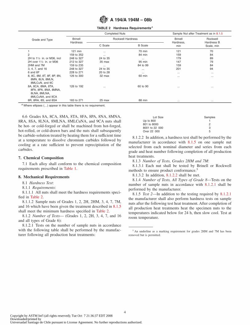
6.6 Grades 8A, 8CA, 8MA, 8TA, 8FA, 8PA, 8NA, 8MNA,8RA, 8SA, 8LNA, 8MLNA, 8MLCuNA, and 9CA nuts shallbe hot- or cold-forged or shall be machined from hot-forged,hot-rolled, or cold-drawn bars and the nuts shall subsequentlybe carbide-solution treated by heating them for a sufficient timeat a temperature to dissolve chromium carbides followed bycooling at a rate sufficient to prevent reprecipitation of thecarbides.
7. Chemical Composition
7.1 Each alloy shall conform to the chemical compositionrequirements prescribed in Table 1.
8. Mechanical Requirements
8.1 Hardness Test:8.1.1 Requirements:8.1.1.1 All nuts shall meet the hardness requirements speci-
fied in Table 2.8.1.1.2 Sample nuts of Grades 1, 2, 2H, 2HM, 3, 4, 7, 7M,
and 16 which have been given the treatment described in 8.1.5shall meet the minimum hardness specified in Table 2.
8.1.2 Number of Tests— (Grades 1, 2, 2H, 3, 4, 7, and 16and all types of Grade 6):
8.1.2.1 Tests on the number of sample nuts in accordancewith the following table shall be performed by the manufac-turer following all production heat treatments:
Lot Size SamplesUp to 800 1801 to 8000 28001 to 22 000 3Over 22 000 5
8.1.2.2 In addition, a hardness test shall be performed by themanufacturer in accordance with 8.1.5 on one sample nutselected from each nominal diameter and series from eachgrade and heat number following completion of all productionheat treatments.
8.1.3 Number of Tests, Grades 2HM and 7M:8.1.3.1 Each nut shall be tested by Brinell or Rockwell
methods to ensure product conformance.5
8.1.3.2 In addition, 8.1.2.2 shall be met.8.1.4 Number of Tests, All Types of Grade 8—Tests on the
number of sample nuts in accordance with 8.1.2.1 shall beperformed by the manufacturer.
8.1.5 Test 2—In addition to the testing required by 8.1.2.1the manufacturer shall also perform hardness tests on samplenuts after the following test heat treatment. After completion ofall production heat treatments heat the specimen nuts to thetemperatures indicated below for 24 h, then slow cool. Test atroom temperature.
5 An underline as a marking requirement for grades 2HM and 7M has beenremoved but is permitted.
TABLE 2 Hardness RequirementsA
Grade and Type
Completed Nuts Sample Nut after Treatment as in 8.1.5
BrinellHardness
Rockwell Hardness BrinellHardness,
min
RockwellHardness BScale, minC Scale B Scale
1 121 min ... 70 min 121 702 159 to 352 ... 84 min 159 842H to 11⁄2 in. or M36, incl 248 to 327 24 to 35 ... 179 892H over 11⁄2 in. or M36 212 to 327 35 max 95 min 147 792HM and 7M 159 to 235 ... 84 to 99 159 843, 4, 7, and 16 248 to 327 24 to 35 ... 201 946 and 6F 228 to 271 20 to 28 ... ... ...8, 8C, 8M, 8T, 8F, 8P, 8N,
8MN, 8LN, 8MLN,8MLCuN, and 9C
126 to 300 32 max 60 min ... ...
8A, 8CA, 8MA, 8TA,8FA, 8PA, 8NA, 8MNA,8LNA, 8MLNA,8MLCuNA, and 9CA
126 to 192 ... 60 to 90 ... ...
8R, 8RA, 8S, and 8SA 183 to 271 25 max 88 min ... ...A Where ellipses (…) appear in this table there is no requirement.
A 194/A 194M – 08b
4Copyright by ASTM Int'l (all rights reserved); Tue Oct 7 21:36:37 EDT 2008Downloaded/printed byUniversadad Santiago de Chile pursuant to License Agreement. No further reproductions authorized.
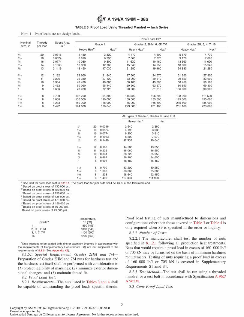
GradeATemperature,
°F [°C]1 850 [455]2, 2H, 2HM 1000 [540]3, 4, 7, 7M 1100 [590]16 1200 [650]
ANuts intended to be coated with zinc or cadmium (marked in accordance withthe requirements of Supplementary Requirement S8) are not subjected to therequirements of 8.1.5 (See Appendix X2).
8.1.5.1 Special Requirement, Grades 2HM and 7M—Preparation of Grades 2HM and 7M nuts for hardness test andthe hardness test itself shall be performed with consideration to(1) protect legibility of markings; (2) minimize exterior dimen-sional changes; and (3) maintain thread fit.
8.2 Proof Load Test:8.2.1 Requirements—The nuts listed in Tables 3 and 4 shall
be capable of withstanding the proof loads specifin therein.
Proof load testing of nuts manufactured to dimensions andconfigurations other than those covered in Table 3 or Table 4 isonly required when S9 is specified in the order or inquiry.
8.2.2 Number of Tests:8.2.2.1 The manufacturer shall test the number of nuts
specified in 8.1.2.1 following all production heat treatments.Nuts that would require a proof load in excess of 160 000 lb/for 705 kN may be furnished on the basis of minimum hardnessrequirements. Testing of nuts requiring a proof load in excessof 160 000 lb/f or 705 kN is covered in SupplementaryRequirements S1 amd S4.
8.2.3 Test Method—The test shall be run using a threadedmandrel or a test bolt in accordance with Specification A 962/A 962M.
8.3 Cone Proof Load Test:
TABLE 3 Proof Load Using Threaded Mandrel — Inch Series
NOTE 1—Proof loads are not design loads.
NominalSize, in.
Threadsper Inch
Stress Areain.2
Proof Load, lbfA
Grade 1 Grades 2, 2HM, 6, 6F, 7M Grades 2H, 3, 4, 7, 16
Heavy HexB HexC Heavy HexD HexE Heavy HexF HexG
1⁄4 20 0.0316 4 130 3 820 4 770 4 300 5 570 4 7705⁄16 18 0.0524 6 810 6 290 7 860 7 070 9 170 7 8603⁄8 16 0.0774 10 080 9 300 11 620 10 460 13 560 11 6207⁄16 14 0.1063 13 820 12 760 15 940 14 350 18 600 15 9401⁄2 13 0.1419 18 450 17 030 21 280 19 160 24 830 21 280
9⁄16 12 0.182 23 660 21 840 27 300 24 570 31 850 27 3005⁄8 11 0.226 29 380 27 120 33 900 30 510 39 550 33 9003⁄4 10 0.334 43 420 40 080 50 100 45 090 58 450 50 1007⁄8 9 0.462 60 060 55 440 69 300 62 370 80 850 69 3001 8 0.606 78 780 72 720 90 900 81 810 106 000 90 900
11⁄8 8 0.790 102 700 94 800 118 500 106 700 138 200 118 50011⁄4 8 1.000 130 000 120 000 150 000 135 000 175 000 150 00013⁄8 8 1.233 160 200 148 000 185 000 166 500 215 800 185 00011⁄2 8 1.492 194 000 170 040 223 800 201 400 261 100 223 800
All Types of Grade 8, Grades 9C and 9CA
Heavy HexH HexI
1⁄4 20 0.0316 2 540 2 3805⁄16 18 0.0524 4 190 3 9303⁄8 16 0.0774 6 200 5 8107⁄16 14 0.1063 8 500 7 9701⁄2 13 0.1419 11 350 10 640
9⁄16 12 0.182 14 560 13 6505⁄8 11 0.226 18 080 16 9503⁄4 10 0.334 26 720 25 0507⁄8 9 0.462 36 960 34 6501 8 0.606 48 480 45 450
11⁄8 8 0.790 63 200 59 25011⁄4 8 1.000 80 000 75 00013⁄8 8 1.233 98 640 92 45011⁄2 8 1.492 119 360 111 900
A See limit for proof load test in 8.2.2.1. The proof load for jam nuts shall be 46 % of the tabulated load.B Based on proof stress of 130 000 psi.C Based on proof stress of 120 000 psi.D Based on proof stress of 150 000 psi.E Based on proof stress of 135 000 psi.F Based on proof stress of 175 000 psi.G Based on proof stress of 150 000 psi.H Based on proof stress of 80 000 psi.I Based on proof stress of 75 000 psi.
A 194/A 194M – 08b
5Copyright by ASTM Int'l (all rights reserved); Tue Oct 7 21:36:37 EDT 2008Downloaded/printed byUniversadad Santiago de Chile pursuant to License Agreement. No further reproductions authorized.
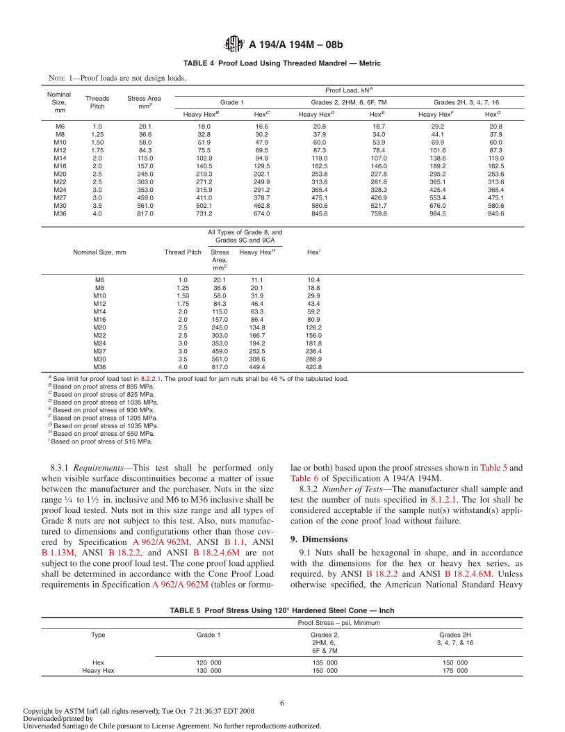
8.3.1 Requirements—This test shall be performed onlywhen visible surface discontinuities become a matter of issuebetween the manufacturer and the purchaser. Nuts in the sizerange 1⁄4 to 11⁄2 in. inclusive and M6 to M36 inclusive shall beproof load tested. Nuts not in this size range and all types ofGrade 8 nuts are not subject to this test. Also, nuts manufac-tured to dimensions and configurations other than those cov-ered by Specification A 962/A 962M, ANSI B 1.1, ANSIB 1.13M, ANSI B 18.2.2, and ANSI B 18.2.4.6M are notsubject to the cone proof load test. The cone proof load appliedshall be determined in accordance with the Cone Proof Loadrequirements in Specification A 962/A 962M (tables or formu-
lae or both) based upon the proof stresses shown in Table 5 andTable 6 of Specification A 194/A 194M.
8.3.2 Number of Tests—The manufacturer shall sample andtest the number of nuts specified in 8.1.2.1. The lot shall beconsidered acceptable if the sample nut(s) withstand(s) appli-cation of the cone proof load without failure.
9. Dimensions
9.1 Nuts shall be hexagonal in shape, and in accordancewith the dimensions for the hex or heavy hex series, asrequired, by ANSI B 18.2.2 and ANSI B 18.2.4.6M. Unlessotherwise specified, the American National Standard Heavy
TABLE 4 Proof Load Using Threaded Mandrel — Metric
NOTE 1—Proof loads are not design loads.
NominalSize,mm
ThreadsPitch
Stress Areamm2
Proof Load, kNA
Grade 1 Grades 2, 2HM, 6, 6F, 7M Grades 2H, 3, 4, 7, 16
Heavy HexB HexC Heavy HexD HexE Heavy HexF HexG
M6 1.0 20.1 18.0 16.6 20.8 18.7 29.2 20.8M8 1.25 36.6 32.8 30.2 37.9 34.0 44.1 37.9M10 1.50 58.0 51.9 47.9 60.0 53.9 69.9 60.0M12 1.75 84.3 75.5 69.5 87.3 78.4 101.6 87.3M14 2.0 115.0 102.9 94.9 119.0 107.0 138.6 119.0M16 2.0 157.0 140.5 129.5 162.5 146.0 189.2 162.5M20 2.5 245.0 219.3 202.1 253.6 227.8 295.2 253.6M22 2.5 303.0 271.2 249.9 313.6 281.8 365.1 313.6M24 3.0 353.0 315.9 291.2 365.4 328.3 425.4 365.4M27 3.0 459.0 411.0 378.7 475.1 426.9 553.4 475.1M30 3.5 561.0 502.1 462.8 580.6 521.7 676.0 580.6M36 4.0 817.0 731.2 674.0 845.6 759.8 984.5 845.6
All Types of Grade 8, andGrades 9C and 9CA
Nominal Size, mm Thread Pitch StressArea,mm2
Heavy HexH HexI
M6 1.0 20.1 11.1 10.4M8 1.25 36.6 20.1 18.8M10 1.50 58.0 31.9 29.9M12 1.75 84.3 46.4 43.4M14 2.0 115.0 63.3 59.2M16 2.0 157.0 86.4 80.9M20 2.5 245.0 134.8 126.2M22 2.5 303.0 166.7 156.0M24 3.0 353.0 194.2 181.8M27 3.0 459.0 252.5 236.4M30 3.5 561.0 308.6 288.9M36 4.0 817.0 449.4 420.8
A See limit for proof load test in 8.2.2.1. The proof load for jam nuts shall be 46 % of the tabulated load.B Based on proof stress of 895 MPa.C Based on proof stress of 825 MPa.D Based on proof stress of 1035 MPa.E Based on proof stress of 930 MPa.F Based on proof stress of 1205 MPa.G Based on proof stress of 1035 MPa.H Based on proof stress of 550 MPa.I Based on proof stress of 515 MPa.
TABLE 5 Proof Stress Using 120° Hardened Steel Cone — Inch
Proof Stress – psi, Minimum
Type Grade 1 Grades 2,2HM, 6,6F & 7M
Grades 2H3, 4, 7, & 16
Hex 120 000 135 000 150 000Heavy Hex 130 000 150 000 175 000
A 194/A 194M – 08b
6Copyright by ASTM Int'l (all rights reserved); Tue Oct 7 21:36:37 EDT 2008Downloaded/printed byUniversadad Santiago de Chile pursuant to License Agreement. No further reproductions authorized.
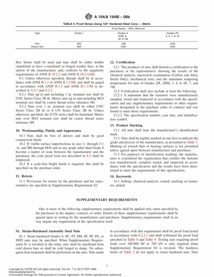
Hex Series shall be used and nuts shall be either doublechamfered or have a machined or forged washer face, at theoption of the manufacturer, and, conform to the angularityrequirements of ANSI B 18.2.2 and ANSI B 18.2.4.6M.
9.2 Unless otherwise specified, threads shall be in accor-dance with ANSI B 1.1 or ANSI B 1.13M, and shall be gagedin accordance with ANSI B 1.2 and ANSI B 1.13M as de-scribed in 9.2.1 and 9.2.2.
9.2.1 Nuts up to and including 1 in. nominal size shall beUNC Series Class 2B fit. Metric nuts up to and including M24nominal size shall be coarse thread series tolerance 6H.
9.2.2 Nuts over 1 in. nominal size shall be either UNCSeries Class 2B fit or 8 UN Series Class 2B fit. Unlessotherwise specified, the 8 UN series shall be furnished. Metricnuts over M24 nominal size shall be coarse thread seriestolerance 6H.
10. Workmanship, Finish, and Appearance
10.1 Nuts shall be free of defects and shall be goodcommercial finish.
10.2 If visible surface imperfections in size 1⁄4 through 11⁄2in. and M6 through M36 and in any grade other than Grade 8become a matter of issue between the manufacturer and thepurchaser, the cone proof load test described in 8.3 shall beemployed.
10.3 If a scale-free bright finish is required, this shall bespecified on the purchase order.
11. Retests
11.1 Provisions for retests by the purchaser and his repre-sentative are specified in Supplementary Requirement S2.
12. Certification12.1 The producer of nuts shall furnish a certification to the
purchaser or his representative showing the results of thechemical analysis, macroetch examination (Carbon and AlloySteels Only), mechanical tests, and the minimum temperingtemperature for nuts of Grades 2H, 2HM, 3, 4, 6, 6F, 7, and7M.
12.2 Certification shall also include at least the following:12.2.1 A statement that the fasteners were manufactured,
sampled, tested and inspected in accordance with the specifi-cation and any supplementary requirements or other require-ments designated in the purchase order or contract and wasfound to meet those requirements.
12.2.2 The specification number, year date, and identifica-tion symbol.
13. Product Marking13.1 All nuts shall bear the manufacturer’s identification
mark.13.2 Nuts shall be legibly marked on one face to indicate the
grade and process of the manufacturer, as presented in Table 7.Marking of wrench flats or bearing surfaces is not permittedunless agreed upon between manufacturer and purchaser.
13.3 For purposes of identification marking, the manufac-turer is considered the organization that certifies the fastenerwas manufactured, sampled, tested, and inspected in accor-dance with the specification and the results have been deter-mined to meet the requirements of this specification.
14. Keywords14.1 bolting; chemical analysis; coated; marking on fasten-
ers; plated
SUPPLEMENTARY REQUIREMENTS
One or more of the following supplementary requirements shall be applied only when specified bythe purchaser in the inquiry, contract, or order. Details of these supplementary requirements shall beagreed upon in writing by the manufacturer and purchaser. Supplementary requirements shall in noway negate any requirement of the specification itself.
S1. Strain-Hardened Austenitic Steel Nuts
S1.1 Strain hardened Grades 8, 8C, 8T, 8M, 8F, 8P, 8N, or8MN nuts may be specified. When Supplementary Require-ment S1 is invoked in the order, nuts shall be machined fromcold drawn bars or shall be cold forged to shape. No subse-quent heat treatment shall be performed on the nuts. Nuts made
in accordance with this requirement shall be proof load testedin accordance with 8.2.2.1 and shall withstand the proof loadspecified in Table 8 and Table 9. Testing nuts requiring proofloads over 160 000 lbf or 705 kN is only required whenSupplementary Requirement S4 is invoked. The hardnesslimits of Table 2 do not apply to strain hardened nuts. Nuts
TABLE 6 Proof Stress Using 120° Hardened Steel Cone — Metric
Proof Stress – MPa, Minimum
Type Grade 1 Grades 2,2HM, 6,6F & 7M
Grades 2H3, 4, 7, & 16
Hex 825 930 1035Heavy Hex 895 1035 1205
A 194/A 194M – 08b
7Copyright by ASTM Int'l (all rights reserved); Tue Oct 7 21:36:37 EDT 2008Downloaded/printed byUniversadad Santiago de Chile pursuant to License Agreement. No further reproductions authorized.
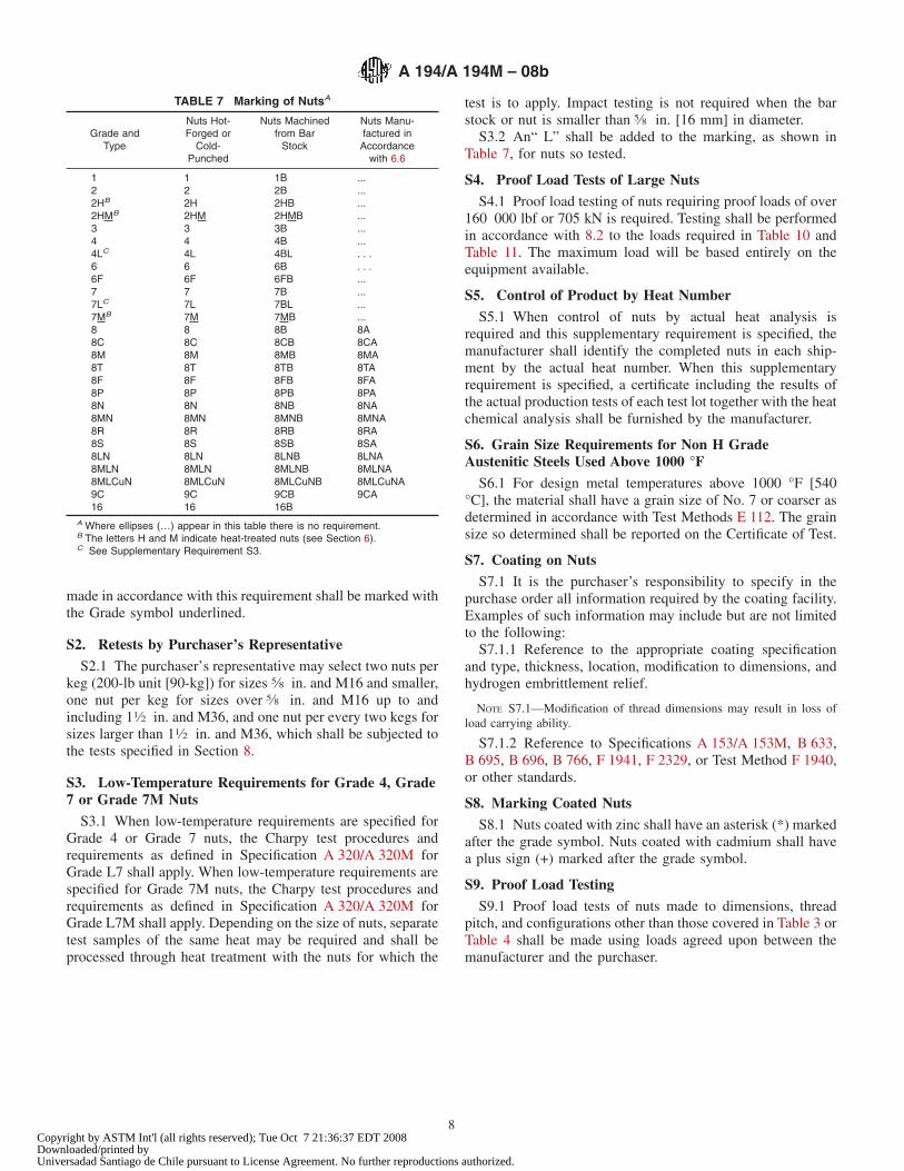
made in accordance with this requirement shall be marked withthe Grade symbol underlined.
S2. Retests by Purchaser’s Representative
S2.1 The purchaser’s representative may select two nuts perkeg (200-lb unit [90-kg]) for sizes 5⁄8 in. and M16 and smaller,one nut per keg for sizes over 5⁄8 in. and M16 up to andincluding 11⁄2 in. and M36, and one nut per every two kegs forsizes larger than 11⁄2 in. and M36, which shall be subjected tothe tests specified in Section 8.
S3. Low-Temperature Requirements for Grade 4, Grade7 or Grade 7M Nuts
S3.1 When low-temperature requirements are specified forGrade 4 or Grade 7 nuts, the Charpy test procedures andrequirements as defined in Specification A 320/A 320M forGrade L7 shall apply. When low-temperature requirements arespecified for Grade 7M nuts, the Charpy test procedures andrequirements as defined in Specification A 320/A 320M forGrade L7M shall apply. Depending on the size of nuts, separatetest samples of the same heat may be required and shall beprocessed through heat treatment with the nuts for which the
test is to apply. Impact testing is not required when the barstock or nut is smaller than 5⁄8 in. [16 mm] in diameter.
S3.2 An“ L” shall be added to the marking, as shown inTable 7, for nuts so tested.
S4. Proof Load Tests of Large Nuts
S4.1 Proof load testing of nuts requiring proof loads of over160 000 lbf or 705 kN is required. Testing shall be performedin accordance with 8.2 to the loads required in Table 10 andTable 11. The maximum load will be based entirely on theequipment available.
S5. Control of Product by Heat Number
S5.1 When control of nuts by actual heat analysis isrequired and this supplementary requirement is specified, themanufacturer shall identify the completed nuts in each ship-ment by the actual heat number. When this supplementaryrequirement is specified, a certificate including the results ofthe actual production tests of each test lot together with the heatchemical analysis shall be furnished by the manufacturer.
S6. Grain Size Requirements for Non H GradeAustenitic Steels Used Above 1000 °F
S6.1 For design metal temperatures above 1000 °F [540°C], the material shall have a grain size of No. 7 or coarser asdetermined in accordance with Test Methods E 112. The grainsize so determined shall be reported on the Certificate of Test.
S7. Coating on Nuts
S7.1 It is the purchaser’s responsibility to specify in thepurchase order all information required by the coating facility.Examples of such information may include but are not limitedto the following:
S7.1.1 Reference to the appropriate coating specificationand type, thickness, location, modification to dimensions, andhydrogen embrittlement relief.
NOTE S7.1—Modification of thread dimensions may result in loss ofload carrying ability.
S7.1.2 Reference to Specifications A 153/A 153M, B 633,B 695, B 696, B 766, F 1941, F 2329, or Test Method F 1940,or other standards.
S8. Marking Coated Nuts
S8.1 Nuts coated with zinc shall have an asterisk (*) markedafter the grade symbol. Nuts coated with cadmium shall havea plus sign (+) marked after the grade symbol.
S9. Proof Load Testing
S9.1 Proof load tests of nuts made to dimensions, threadpitch, and configurations other than those covered in Table 3 orTable 4 shall be made using loads agreed upon between themanufacturer and the purchaser.
TABLE 7 Marking of NutsA
Grade andType
Nuts Hot-Forged or
Cold-Punched
Nuts Machinedfrom Bar
Stock
Nuts Manu-factured inAccordance
with 6.6
1 1 1B ...2 2 2B ...2HB 2H 2HB ...2HMB 2HM 2HMB ...3 3 3B ...4 4 4B ...4LC 4L 4BL . . .6 6 6B . . .6F 6F 6FB ...7 7 7B ...7LC 7L 7BL ...7MB 7M 7MB ...8 8 8B 8A8C 8C 8CB 8CA8M 8M 8MB 8MA8T 8T 8TB 8TA8F 8F 8FB 8FA8P 8P 8PB 8PA8N 8N 8NB 8NA8MN 8MN 8MNB 8MNA8R 8R 8RB 8RA8S 8S 8SB 8SA8LN 8LN 8LNB 8LNA8MLN 8MLN 8MLNB 8MLNA8MLCuN 8MLCuN 8MLCuNB 8MLCuNA9C 9C 9CB 9CA16 16 16B
A Where ellipses (…) appear in this table there is no requirement.B The letters H and M indicate heat-treated nuts (see Section 6).C See Supplementary Requirement S3.
A 194/A 194M – 08b
8Copyright by ASTM Int'l (all rights reserved); Tue Oct 7 21:36:37 EDT 2008Downloaded/printed byUniversadad Santiago de Chile pursuant to License Agreement. No further reproductions authorized.
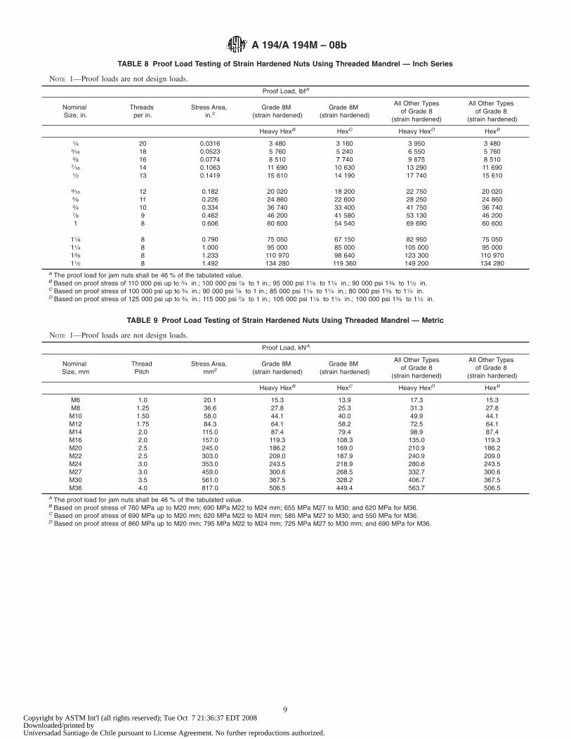
TABLE 8 Proof Load Testing of Strain Hardened Nuts Using Threaded Mandrel — Inch Series
NOTE 1—Proof loads are not design loads.
Proof Load, lbfA
NominalSize, in.
Threadsper in.
Stress Area,in.2
Grade 8M(strain hardened)
Grade 8M(strain hardened)
All Other Typesof Grade 8
(strain hardened)
All Other Typesof Grade 8
(strain hardened)
Heavy HexB HexC Heavy HexD HexB
1⁄4 20 0.0316 3 480 3 160 3 950 3 4805⁄16 18 0.0523 5 760 5 240 6 550 5 7603⁄8 16 0.0774 8 510 7 740 9 675 8 5107⁄16 14 0.1063 11 690 10 630 13 290 11 6901⁄2 13 0.1419 15 610 14 190 17 740 15 610
9⁄16 12 0.182 20 020 18 200 22 750 20 0205⁄8 11 0.226 24 860 22 600 28 250 24 8603⁄4 10 0.334 36 740 33 400 41 750 36 7407⁄8 9 0.462 46 200 41 580 53 130 46 2001 8 0.606 60 600 54 540 69 690 60 600
11⁄8 8 0.790 75 050 67 150 82 950 75 05011⁄4 8 1.000 95 000 85 000 105 000 95 00013⁄8 8 1.233 110 970 98 640 123 300 110 97011⁄2 8 1.492 134 280 119 360 149 200 134 280
A The proof load for jam nuts shall be 46 % of the tabulated value.B Based on proof stress of 110 000 psi up to 3⁄4 in.; 100 000 psi 7⁄8 to 1 in.; 95 000 psi 11⁄8 to 11⁄4 in.; 90 000 psi 13⁄8 to 11⁄2 in.C Based on proof stress of 100 000 psi up to 3⁄4 in.; 90 000 psi 7⁄8 to 1 in.; 85 000 psi 11⁄8 to 11⁄4 in.; 80 000 psi 13⁄8 to 11⁄2 in.D Based on proof stress of 125 000 psi up to 3⁄4 in.; 115 000 psi 7⁄8 to 1 in.; 105 000 psi 11⁄8 to 11⁄4 in.; 100 000 psi 13⁄8 to 11⁄2 in.
TABLE 9 Proof Load Testing of Strain Hardened Nuts Using Threaded Mandrel — Metric
NOTE 1—Proof loads are not design loads.
Proof Load, kNA
NominalSize, mm
ThreadPitch
Stress Area,mm2
Grade 8M(strain hardened)
Grade 8M(strain hardened)
All Other Typesof Grade 8
(strain hardened)
All Other Typesof Grade 8
(strain hardened)
Heavy HexB HexC Heavy HexD HexB
M6 1.0 20.1 15.3 13.9 17.3 15.3M8 1.25 36.6 27.8 25.3 31.3 27.8M10 1.50 58.0 44.1 40.0 49.9 44.1M12 1.75 84.3 64.1 58.2 72.5 64.1M14 2.0 115.0 87.4 79.4 98.9 87.4M16 2.0 157.0 119.3 108.3 135.0 119.3M20 2.5 245.0 186.2 169.0 210.9 186.2M22 2.5 303.0 209.0 187.9 240.9 209.0M24 3.0 353.0 243.5 218.9 280.6 243.5M27 3.0 459.0 300.6 268.5 332.7 300.6M30 3.5 561.0 367.5 328.2 406.7 367.5M36 4.0 817.0 506.5 449.4 563.7 506.5
A The proof load for jam nuts shall be 46 % of the tabulated value.B Based on proof stress of 760 MPa up to M20 mm; 690 MPa M22 to M24 mm; 655 MPa M27 to M30; and 620 MPa for M36.C Based on proof stress of 690 MPa up to M20 mm; 620 MPa M22 to M24 mm; 585 MPa M27 to M30; and 550 MPa for M36.D Based on proof stress of 860 MPa up to M20 mm; 795 MPa M22 to M24 mm; 725 MPa M27 to M30 mm; and 690 MPa for M36.
A 194/A 194M – 08b
9Copyright by ASTM Int'l (all rights reserved); Tue Oct 7 21:36:37 EDT 2008Downloaded/printed byUniversadad Santiago de Chile pursuant to License Agreement. No further reproductions authorized.
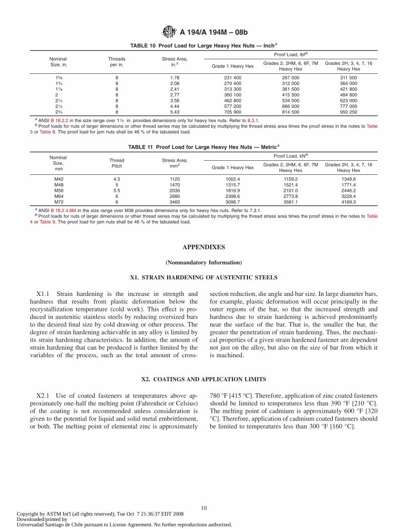
APPENDIXES
(Nonmandatory Information)
X1. STRAIN HARDENING OF AUSTENITIC STEELS
X1.1 Strain hardening is the increase in strength andhardness that results from plastic deformation below therecrystallization temperature (cold work). This effect is pro-duced in austenitic stainless steels by reducing oversized barsto the desired final size by cold drawing or other process. Thedegree of strain hardening achievable in any alloy is limited byits strain hardening characteristics. In addition, the amount ofstrain hardening that can be produced is further limited by thevariables of the process, such as the total amount of cross-
section reduction, die angle and bar size. In large diameter bars,for example, plastic deformation will occur principally in theouter regions of the bar, so that the increased strength andhardness due to strain hardening is achieved predominantlynear the surface of the bar. That is, the smaller the bar, thegreater the penetration of strain hardening. Thus, the mechani-cal properties of a given strain hardened fastener are dependentnot just on the alloy, but also on the size of bar from which itis machined.
X2. COATINGS AND APPLICATION LIMITS
X2.1 Use of coated fasteners at temperatures above ap-proximately one-half the melting point (Fahrenheit or Celsius)of the coating is not recommended unless consideration isgiven to the potential for liquid and solid metal embrittlement,or both. The melting point of elemental zinc is approximately
780 °F [415 °C]. Therefore, application of zinc coated fastenersshould be limited to temperatures less than 390 °F [210 °C].The melting point of cadmium is approximately 600 °F [320°C]. Therefore, application of cadmium coated fasteners shouldbe limited to temperatures less than 300 °F [160 °C].
TABLE 10 Proof Load for Large Heavy Hex Nuts — InchA
NominalSize, in.
Threadsper in.
Stress Area,in.2
Proof Load, lbfB
Grade 1 Heavy HexGrades 2, 2HM, 6, 6F, 7M
Heavy HexGrades 2H, 3, 4, 7, 16
Heavy Hex
15⁄8 8 1.78 231 400 267 000 311 50013⁄4 8 2.08 270 400 312 000 364 00017⁄8 8 2.41 313 300 361 500 421 8002 8 2.77 360 100 415 500 484 80021⁄4 8 3.56 462 800 534 000 623 00021⁄2 8 4.44 577 200 666 000 777 00023⁄4 8 5.43 705 900 814 500 950 250
A ANSI B 18.2.2 in the size range over 11⁄2 in. provides dimensions only for heavy hex nuts. Refer to 8.3.1.B Proof loads for nuts of larger dimensions or other thread series may be calculated by multiplying the thread stress area times the proof stress in the notes to Table
3 or Table 8. The proof load for jam nuts shall be 46 % of the tabulated load.
TABLE 11 Proof Load for Large Heavy Hex Nuts — MetricA
NominalSize,mm
ThreadPitch
Stress Area,mm2
Proof Load, kNB
Grade 1 Heavy HexGrades 2, 2HM, 6, 6F, 7M
Heavy HexGrades 2H, 3, 4, 7, 16
Heavy Hex
M42 4.5 1120 1002.4 1159.2 1349.6M48 5 1470 1315.7 1521.4 1771.4M56 5.5 2030 1816.9 2101.0 2446.2M64 6 2680 2398.6 2773.8 3229.4M72 6 3460 3096.7 3581.1 4169.3
A ANSI B 18.2.4.6M in the size range over M36 provides dimensions only for heavy hex nuts. Refer to 7.3.1.B Proof loads for nuts of larger dimensions or other thread series may be calculated by multiplying the thread stress area times the proof stress in the notes to Table
4 or Table 9. The proof load for jam nuts shall be 46 % of the tabulated load.
A 194/A 194M – 08b
10Copyright by ASTM Int'l (all rights reserved); Tue Oct 7 21:36:37 EDT 2008Downloaded/printed byUniversadad Santiago de Chile pursuant to License Agreement. No further reproductions authorized.
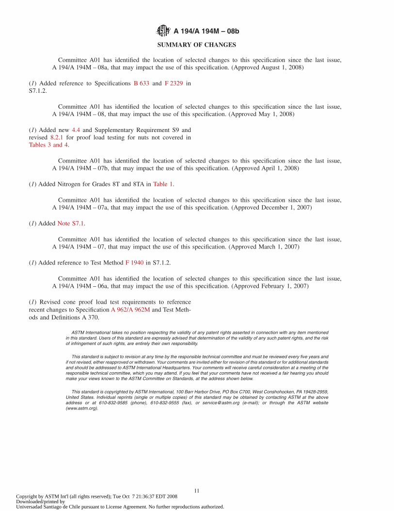
SUMMARY OF CHANGES
Committee A01 has identified the location of selected changes to this specification since the last issue,A 194/A 194M – 08a, that may impact the use of this specification. (Approved August 1, 2008)
(1) Added reference to Specifications B 633 and F 2329 inS7.1.2.
Committee A01 has identified the location of selected changes to this specification since the last issue,A 194/A 194M – 08, that may impact the use of this specification. (Approved May 1, 2008)
(1) Added new 4.4 and Supplementary Requirement S9 andrevised 8.2.1 for proof load testing for nuts not covered inTables 3 and 4.
Committee A01 has identified the location of selected changes to this specification since the last issue,A 194/A 194M – 07b, that may impact the use of this specification. (Approved April 1, 2008)
(1) Added Nitrogen for Grades 8T and 8TA in Table 1.
Committee A01 has identified the location of selected changes to this specification since the last issue,A 194/A 194M – 07a, that may impact the use of this specification. (Approved December 1, 2007)
(1) Added Note S7.1.
Committee A01 has identified the location of selected changes to this specification since the last issue,A 194/A 194M – 07, that may impact the use of this specification. (Approved March 1, 2007)
(1) Added reference to Test Method F 1940 in S7.1.2.
Committee A01 has identified the location of selected changes to this specification since the last issue,A 194/A 194M – 06a, that may impact the use of this specification. (Approved February 1, 2007)
(1) Revised cone proof load test requirements to referencerecent changes to Specification A 962/A 962M and Test Meth-ods and Definitions A 370.
ASTM International takes no position respecting the validity of any patent rights asserted in connection with any item mentionedin this standard. Users of this standard are expressly advised that determination of the validity of any such patent rights, and the riskof infringement of such rights, are entirely their own responsibility.
This standard is subject to revision at any time by the responsible technical committee and must be reviewed every five years andif not revised, either reapproved or withdrawn. Your comments are invited either for revision of this standard or for additional standardsand should be addressed to ASTM International Headquarters. Your comments will receive careful consideration at a meeting of theresponsible technical committee, which you may attend. If you feel that your comments have not received a fair hearing you shouldmake your views known to the ASTM Committee on Standards, at the address shown below.
This standard is copyrighted by ASTM International, 100 Barr Harbor Drive, PO Box C700, West Conshohocken, PA 19428-2959,United States. Individual reprints (single or multiple copies) of this standard may be obtained by contacting ASTM at the aboveaddress or at 610-832-9585 (phone), 610-832-9555 (fax), or [email protected] (e-mail); or through the ASTM website(www.astm.org).
A 194/A 194M – 08b
11Copyright by ASTM Int'l (all rights reserved); Tue Oct 7 21:36:37 EDT 2008Downloaded/printed byUniversadad Santiago de Chile pursuant to License Agreement. No further reproductions authorized.