OS-782 manual de instrucciones / user manual · 2014-12-12 · OS-782 02-2010 Página 4...
136
OS-782 OSCILOSCOPIO Y MULTÍMETRO DIGITAL DIGITAL OSCILLOSCOPE & MULTIMETER - 0 MI1737 -
Transcript of OS-782 manual de instrucciones / user manual · 2014-12-12 · OS-782 02-2010 Página 4...
OS-782
OSCILOSCOPIO Y MULTÍMETRO DIGITAL
DIGITAL OSCILLOSCOPE & MULTIMETER
- 0 MI1737 -


NOTAS SOBRE SEGURIDAD Antes de manipular el equipo leer el manual de instrucciones y muy especialmente el apartado PRESCRIPCIONES DE SEGURIDAD.
El símbolo sobre el equipo significa "CONSULTAR EL MANUAL DE INSTRUCCIONES". En este manual puede aparecer también como símbolo de advertencia o precaución. Recuadros de ADVERTENCIAS Y PRECAUCIONES pueden aparecer a lo largo de este manual para evitar riesgos de accidentes a personas o daños al equipo u otras propiedades.
SAFETY NOTES Read the user’s manual before using the equipment, mainly " SAFETY RULES " paragraph.
The symbol on the equipment means "SEE USER’S MANUAL". In this manual may also appear as a Caution or Warning symbol. Warning and Caution statements may appear in this manual to avoid injury hazard or damage to this product or other property.

SUMARIO
CONTENTS
Manual español............................................................. English manual .............................................................
Eng
lish


MANUAL DE INSTRUCCIONES. OS-782
Í N D I C E 1. GENERALIDADES .................................................................................................... 1
1.1 Descripción.......................................................................................................... 1 1.2 Especificaciones Osciloscopio ............................................................................ 2 1.3 Especificaciones Multímetro................................................................................ 5
2. PRESCRIPCIONES DE SEGURIDAD ...................................................................... 7 2.1 Generales............................................................................................................ 7 2.2 Ejemplos Descriptivos de las Categorías de Sobretensión ................................ 8
3. DESCRIPCIÓN DE MANDOS Y ELEMENTOS ........................................................ 9 4. UTILIZACIÓN DEL OSCILOSCOPIO...................................................................... 11
4.1 Encendido del osciloscopio ............................................................................... 11 4.2 Carga del osciloscopio ...................................................................................... 11 4.3 Pantalla del osciloscopio ................................................................................... 12 4.4 Navegación por los menús................................................................................ 14 4.5 Ajuste manual de los ejes vertical y horizontal y de la posición de disparo...... 15 4.6 Reiniciar el osciloscopio .................................................................................... 18 4.7 Visualización automática de una señal desconocida........................................ 18 4.8 Puesta a cero automática de la posición horizontal y el nivel de disparo ......... 19 4.9 Medidas automáticas ........................................................................................ 19 4.10 Congelación de la imagen en pantalla .............................................................. 20 4.11 Ajuste del eje vertical de CH1 y CH2. Función CANAL 1/ CANAL 2. ............... 21
4.11.1 Ajuste del acoplo del canal ......................................................................... 22 4.11.2 Configuración de activación/desactivación del canal ................................. 23 4.11.3 Ajuste de la escala de sonda ...................................................................... 23 4.11.4 Ajuste de forma de onda invertida .............................................................. 24
4.12 Funciones matemáticas “MATH”....................................................................... 24 4.13 Ajuste del sistema de disparo. Función TRIGGER ........................................... 25 4.14 Control de disparo ............................................................................................. 26
4.14.1 Disparo por Flanco...................................................................................... 27 4.14.2 Menús de disparo por video........................................................................ 28
4.15 Ajustes del modo de adquisición. FUNCIÓN ADQUIRIR.................................. 30 4.16 Ajustes de pantalla. Función DISPLAY. ............................................................ 31
Configuraciones ...................................................................................................... 31 4.16.1 Estilo de visualización................................................................................. 31 4.16.2 Persistencia ................................................................................................ 32 4.16.3 Modo XY ..................................................................................................... 32
4.17 Ajustes para guardar las formas de onda. Función MEMORIA. ....................... 33 4.18 Menú de Sistema. Función SISTEMA............................................................... 34 4.19 Medidas automáticas. Funciones MEDIDA 1 y MEDIDA 2. .............................. 35 4.20 Función CURSORES ........................................................................................ 38 4.21 Auto-Escala ....................................................................................................... 40 4.22 Menú de estado del sistema. Función ESTADO............................................... 43 4.23 Ajuste del eje horizontal. Función HORIZONTAL. ............................................ 43 4.24 Transmisión de datos al PC .............................................................................. 45

MANUAL DE INSTRUCCIONES. OS-782
5. UTILIZACIÓN DEL MULTÍMETRO.......................................................................... 47 5.1 Sobre este capítulo ........................................................................................... 47 5.2 Conexiones del multímetro................................................................................ 47 5.3 Pantalla del multímetro...................................................................................... 47 5.4 Medir con el multímetro..................................................................................... 48
5.4.1 Medición de valores de Resistencia ........................................................... 49 5.4.2 Medición de un Diodo. ................................................................................ 49 5.4.3 Prueba continuidad. .................................................................................... 50 5.4.4 Medición de una Capacitancia.................................................................... 51 5.4.5 Medición de voltaje en Corriente Continua (VDC) ...................................... 52 5.4.6 Medición de voltaje en Corriente Alterna (VAC) ......................................... 52 5.4.7 Medición de corriente en Corriente Continua (ADC) .................................. 53 5.4.8 Medición de corriente en Corriente Alterna (ACA)...................................... 55
5.5 Congelación de las lecturas en pantalla............................................................ 56 5.6 Toma de una medida relativa............................................................................ 57 5.7 Selección de rango automático/manual ............................................................ 58
6. POSIBLES PROBLEMAS Y SOLUCIONES............................................................ 59 7. MANTENIMIENTO Y LIMPIEZA.............................................................................. 61
7.1 Mantenimiento básico ....................................................................................... 61 7.2 Limpieza ........................................................................................................... 61 7.3 Almacenaje de osciloscopio .............................................................................. 61 7.4 Sustitución de la batería de litio. ....................................................................... 61

MANUAL DE INSTRUCCIONES. OS-782
Página 1 02-2010
Osciloscopio y Multímetro Portátil Digital
OS-782
1. GENERALIDADES
1.1 Descripción
El Poliscopio OS-782 integra en sí mismo dos instrumentos de medida: osciloscopio digital y multímetro digital. Su robusta construcción, tamaño, peso y alimentación mediante baterías, hacen de él un instrumento portátil apto para realizar múltiples medidas en exteriores, donde trabajar con equipos convencionales resulta muy incómodo. Es muy útil en la medida de magnitudes eléctricas y en la reparación de equipos electrónicos dada su gran diversidad de funciones, lo que hace que a su vez sea un elemento indispensable en laboratorios, ya sea de investigación y desarrollo o de enseñanza.
Las medidas realizadas por el equipo se presentan en una pantalla de cristal líquido de alta resolución con iluminación posterior.
Sus características principales en cada uno de sus modos de funcionamiento son:
• Osciloscopio de dos canales, ancho de banda de 20 MHz.
• Velocidad de muestreo de 100 MSa/s.
• Sincronísmo TV y sincronísmo por flancos.
• 20 Medidas automáticas.
• Función Autoescala.
• Profundidad de memoria de 6k puntos por canal.
• Puerto USB.
• Multímetro digital de 3 ¾ para medidas de R, V, A y C.
• Adaptador AC y batería de LI-ion.
• Pantalla LCD color de 3,8” con retroiluminación, 320 x 240 píxels.
• Cursores verticales y horizontales.

MANUAL DE INSTRUCCIONES. OS-782
02-2010 Página 2
1.2 Especificaciones Osciloscopio
Todas las especificaciones se aplican a la sonda con un ajuste de atenuación 10X y al osciloscopio digital de serie HDS. Para verificar que el osciloscopio cumple las especificaciones, éste debe cumplir las siguientes condiciones:
• El osciloscopio debe haber estado funcionando de forma continua durante treinta minutos en un ambiente con la temperatura de funcionamiento especificada.
• Debe realizar un Auto calibrado, al que se accede mediante el Menú de
funciones, si la temperatura de funcionamiento cambia en más de 5 °C.
Todas las especificaciones están garantizadas, excepto las que se indican como “típicas”. MUESTREO
Modos de muestreo Muestreo normal. Detección de picos.
Valor promedio. Velocidad de muestreo 100 MSa/s.
ENTRADA
Acoplamiento de entrada DC, AC, Tierra. Impedancia de entrada 1MΩ ± 2 % conectado en paralelo con
20pF ±5pF. Coeficiente de atenuación de sonda 1x, 10x, 100x, 1000x. Tensión máxima de entrada 400V (pico). Retraso del canal (típico) 150ps.
HORIZONTAL
Rango de velocidades de 10S/s ~ 100MS/s. muestreo Interpolación de formas de onda (sin x)/x. Longitud de registro 6 K puntos por canal Rango de velocidad de escaneo (S/div) 5ns/div ~ 100s/div, en pasos de 1 - 2.5 o 5. Precisión de velocidad de muestreo y de tiempo de retardo ±100 ppm (sobre cualquier intervalo de tiempo
de igual o mayor que 1 ms).
MANUAL DE INSTRUCCIONES. OS-782
Página 3 02-2010
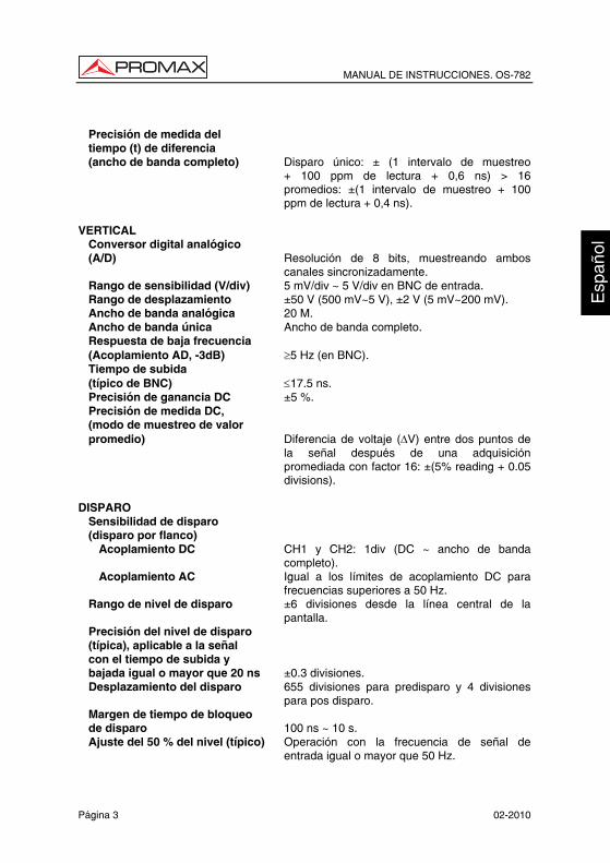
Precisión de medida del tiempo (t) de diferencia (ancho de banda completo) Disparo único: ± (1 intervalo de muestreo
+ 100 ppm de lectura + 0,6 ns) > 16 promedios: ±(1 intervalo de muestreo + 100 ppm de lectura + 0,4 ns).
VERTICAL
Conversor digital analógico (A/D) Resolución de 8 bits, muestreando ambos
canales sincronizadamente. Rango de sensibilidad (V/div) 5 mV/div ~ 5 V/div en BNC de entrada. Rango de desplazamiento ±50 V (500 mV~5 V), ±2 V (5 mV~200 mV). Ancho de banda analógica 20 M. Ancho de banda única Ancho de banda completo. Respuesta de baja frecuencia (Acoplamiento AD, -3dB) ≥5 Hz (en BNC). Tiempo de subida (típico de BNC) ≤17.5 ns. Precisión de ganancia DC ±5 %. Precisión de medida DC, (modo de muestreo de valor promedio) Diferencia de voltaje (∆V) entre dos puntos de
la señal después de una adquisición promediada con factor 16: ±(5% reading + 0.05 divisions).
DISPARO
Sensibilidad de disparo (disparo por flanco)
Acoplamiento DC CH1 y CH2: 1div (DC ~ ancho de banda completo).
Acoplamiento AC Igual a los límites de acoplamiento DC para frecuencias superiores a 50 Hz.
Rango de nivel de disparo ±6 divisiones desde la línea central de la pantalla.
Precisión del nivel de disparo (típica), aplicable a la señal con el tiempo de subida y bajada igual o mayor que 20 ns ±0.3 divisiones. Desplazamiento del disparo 655 divisiones para predisparo y 4 divisiones
para pos disparo. Margen de tiempo de bloqueo de disparo 100 ns ~ 10 s. Ajuste del 50 % del nivel (típico) Operación con la frecuencia de señal de
entrada igual o mayor que 50 Hz.

MANUAL DE INSTRUCCIONES. OS-782
02-2010 Página 4
Sensibilidad, tipo de disparo por video (típica) Amplitud de pico a pico de 2 divisiones. Formatos de señal y velocidades de campo, tipo de disparo de vídeo Admite sistemas de difusión NTSC, PAL y
SECAM para cualquier campo o línea. MEDIDA
Medida de cursores Diferencia de voltaje (∆V) y diferencia de tiempo (∆T) entre cursores.
Medida automática Valor de pico a pico, valor promedio, valor eficaz, frecuencia, ciclo, período, valor máximo, valor mínimo, valor tope, valor base, valor amplitud, valor exceso, valor defecto, tiempo de subida, tiempo de bajada, +Ancho, -Ancho, +Ciclo de funcionamiento, -Ciclo de funcionamiento, retardo de subida y retardo de bajada.
ESPECIFICACIONES GENERALES Visualización
Tipo de pantalla 3.8" pantalla LCD color. Resolución de pantalla Píxeles: 320 (horizontal) X 240 (vertical). Colores de la pantalla 4096 colores.
Características mecánicas Dimensiones 180 (A) x 115 (Al) x 40 (Pr) mm. Peso 0,645 kg.
Alimentación Interna Batería integrada recargable de Li Ion 7,4 V. Externa Adaptador de red incluido para Europa y otros
países. Entrada 100-240 VAC 50Hz / 6W. Potencia de salida 8,5 VDC. Corriente de salida 1500 mA. Batería Batería integrada de 7.4V.
Condiciones de funcionamiento Temperatura en funcionamiento De 0 a 50 °C. Con adaptador de red De 0 a 40 °C.
Temperatura de almacenamiento De -20 a +60 °C. Humedad en funcionamiento
De 0 a 10 °C Sin condensación. De 10 a 30 °C 95 %. De 30 a 40 °C 75 %. De 40 a 50 °C 45 %.
Humedad de almacenamiento De 0 a 10 °C Sin condensación.

MANUAL DE INSTRUCCIONES. OS-782
Página 5 02-2010
ACCESORIOS Dos sondas SA16 x1 x10. Puntas de prueba para el multímetro PP-013. Un cable de comunicación para puerto USB. Un módulo de extensión de medida para corrientes elevadas. Un módulo de extensión de medida para capacitancia pequeña. Un alimentador AC, para Europa y otros países AL-782. Un manual de usuario 0 MI1452. Un CD con software. 1.3 Especificaciones Multímetro Tensión máxima de los bornes de medida a tierra 400V CATII. Tensión continua (VDC)
Impedancia de entrada: 10 MΩ
Rango Precisión Resolución 400 mV 100 µV 4.000 V 1 mV 40.00 V 10 mV 400.0 V
± 1% ± 1 dígito
100 mV
Protección de entrada 1000 VDC o pico AC. Tensión alterna (VAC)
Impedancia de entrada: 10 MΩ. Rango de frecuencia: de 40 Hz a 400 Hz. Visualización: valor virtual de la forma de onda sinusoidal.
Rango Precisión Resolución 4.000 V 1 mV 40.00 V 10 mV 400.0 V
± 1% ± 3 dígitos 100 mV
Protección de entrada 750 VDC o pico AC.
MANUAL DE INSTRUCCIONES. OS-782
02-2010 Página 6
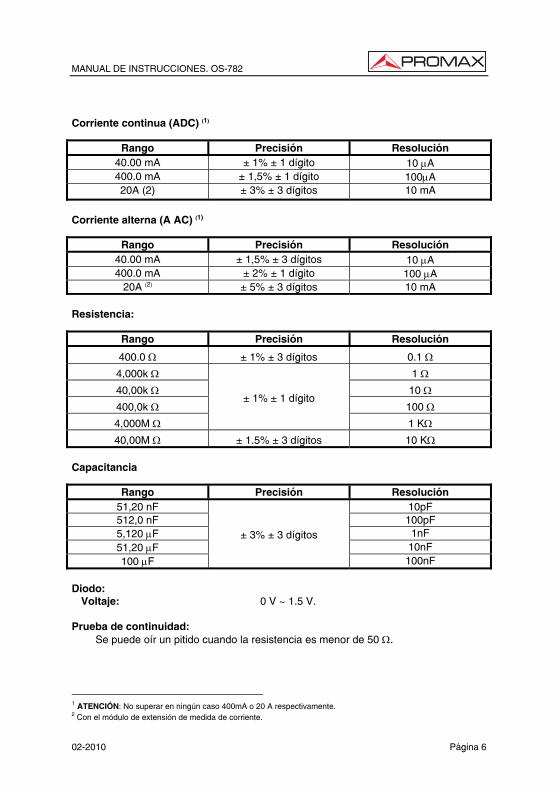
Corriente continua (ADC) (1)
Rango Precisión Resolución 40.00 mA ± 1% ± 1 dígito 10 µA 400.0 mA ± 1,5% ± 1 dígito 100µA 20A (2) ± 3% ± 3 dígitos 10 mA
Corriente alterna (A AC) (1)
Rango Precisión Resolución 40.00 mA ± 1,5% ± 3 dígitos 10 µA 400.0 mA ± 2% ± 1 dígito 100 µA
20A (2) ± 5% ± 3 dígitos 10 mA Resistencia:
Rango Precisión Resolución
400.0 Ω ± 1% ± 3 dígitos 0.1 Ω
4,000k Ω 1 Ω
40,00k Ω 10 Ω
400,0k Ω 100 Ω
4,000M Ω
± 1% ± 1 dígito
1 KΩ
40,00M Ω ± 1.5% ± 3 dígitos 10 KΩ Capacitancia
Rango Precisión Resolución 51,20 nF 10pF 512,0 nF 100pF 5,120 µF 1nF 51,20 µF 10nF 100 µF
± 3% ± 3 dígitos
100nF Diodo:
Voltaje: 0 V ~ 1.5 V. Prueba de continuidad:
Se puede oír un pitido cuando la resistencia es menor de 50 Ω.
1 ATENCIÓN: No superar en ningún caso 400mA o 20 A respectivamente. 2 Con el módulo de extensión de medida de corriente.

MANUAL DE INSTRUCCIONES. OS-782
Página 7 02-2010
2. PRESCRIPCIONES DE SEGURIDAD
2.1 Generales
* Utilizar el equipo como OSCILOSCOPIO solamente en sistemas con el negativo de medida conectado a tensiones no peligrosas respecto al potencial de tierra.
* Utilizar el equipo como MULTIMETRO solamente en puntos con un potencial máximo de 400V respecto al potencial de tierra y categoría de Sobretensión CAT II.
* Este equipo puede ser utilizado en instalaciones con Categoría de Sobretensión II y ambientes con Grado de Polución 2.
El adaptador de red puede ser utilizado solamente en interiores.
* Al emplear cualquiera de los siguientes accesorios debe hacerse sólo con los tipos especificados a fin de preservar la seguridad:
Alimentador DC externo.
Puntas de prueba (Multímetro).
Sondas de medida (Osciloscopio).
* El negativo de medida como Osciloscopio es común al potencial negativo del conector de entrada / salida de datos.
* El negativo de medida de los canales del osciloscopio es común.
* Al efectuar medidas desconectar los cables que no se utilicen.
* Revise el estado de las puntas de prueba antes de la utilización.
* Tener siempre en cuenta los márgenes especificados tanto para alimentación como para medida.
* Recuerde que las tensiones superiores a 70 V DC o 33 V AC rms son potencialmente peligrosas.
* Observar en todo momento las condiciones ambientales máximas especificadas para el aparato.
* El operador no está autorizado a intervenir en el interior del equipo. Cualquier cambio en el equipo deberá ser efectuado exclusivamente por personal especializado.
* No impedir la ventilación del equipo.
* Seguir estrictamente las recomendaciones de limpieza que se describen en el apartado Mantenimiento.
MANUAL DE INSTRUCCIONES. OS-782
02-2010 Página 8
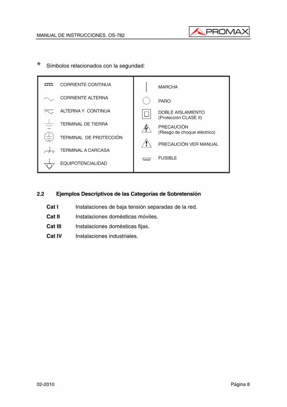
* Símbolos relacionados con la seguridad:
CORRIENTE CONTINUA
CORRIENTE ALTERNA
ALTERNA Y CONTINUA
TERMINAL DE TIERRA
TERMINAL DE PROTECCIÓN
TERMINAL A CARCASA
EQUIPOTENCIALIDAD
MARCHA
PARO
DOBLE AISLAMIENTO(Protección CLASE II)
PRECAUCIÓN(Riesgo de choque eléctrico)
PRECAUCIÓN VER MANUAL
FUSIBLE
2.2 Ejemplos Descriptivos de las Categorías de Sobretensión Cat I Instalaciones de baja tensión separadas de la red.
Cat II Instalaciones domésticas móviles.
Cat III Instalaciones domésticas fijas.
Cat IV Instalaciones industriales.

MANUAL DE INSTRUCCIONES. OS-782
Página 9 02-2010
3. DESCRIPCIÓN DE MANDOS Y ELEMENTOS
En la Figura 1 se pueden observar los distintos controles del equipo:
Figura 1.- Panel frontal del equipo. Descripción:
1. Conector alimentación DC.
2. Puerto USB.
3. Interruptor encendido / apagado de la retroiluminación.
4. POWER : Tecla de encendido / apagado.
5. A: Tecla de medida de corriente.
6. V: Tecla de medida de voltaje.

MANUAL DE INSTRUCCIONES. OS-782
02-2010 Página 10
7. R: Tecla de medida de resistencia, diodo, continuidad y capacitancia.
8. OSC : Tecla de cursor “izquierda” del osciloscopio.
9. OSC : Tecla de cursor “derecha” del osciloscopio.
10. OSC OPTION: Tecla de ajuste de osciloscopio. Combinando las cuatro teclas “OSC ”, “OSC ”, “OSC ” y “OSC ”, se pueden hacer las configuraciones siguientes pulsando “OSC OPTION”. Las configuraciones incluyen: escala vertical del Canal 1 (CH1 VOL) y Canal 2 (CH2 VOL); Base de tiempos primaria (TIME BASE); punto cero del Canal 1 (CH1 ZERO); punto cero del Canal 2 (CH2 ZERO), posición horizontal de disparo (TIME) y posición del nivel de disparo (TRIG).
• El usuario puede también ajustar la escala vertical (CHM VOL) y la
posición horizontal (CHM ZERO) de la señal resultante de una operación matemática.
• En el modo de medida con cursor, se pueden ajustar las posiciones del cursor 1 (V1 o T1) y del cursor 2 (V2 o T2).
11. OSC : Tecla de cursor “abajo” del osciloscopio.
12. OSC : Tecla de cursor “Arriba” del osciloscopio.
13. OSC / DMM: Tecla de cambio de modo Osciloscopio / Multímetro.
14. AUTOSET:
• En Modo Multímetro, al medir corriente o voltaje, se puede cambiar de medida de corriente alterna a corriente continua pulsando esta tecla; al medir resistencia, se puede seleccionar medida de resistencia, diodo, continuidad o capacitancia pulsando esta tecla.
• En Modo Osciloscopio esta tecla sirve para auto-configuración.
15. RUN/STOP: Tecla para ejecutar o detener la operación de medida.
16. MENU : Elige el elemento inferior en la lista del menú.
17. MENU: Muestra / oculta el menú en pantalla.
18. MENU : Elige el elemento superior en la lista del menú.
19. F1~F5: Permite modificar las opciones de cada menú.
20. Conectores BCN de entrada de los canales del osciloscopio: CH1 y CH2.
21. Terminales de entrada del multímetro: tres terminales tipo banana mA/A, COM, V/Ω/C y dos terminales cuadrangulares para medición de capacitancia.
22. Salida de compensación de sonda. Señal de test de 5 Vpp y 1 kHz de frecuencia.

MANUAL DE INSTRUCCIONES. OS-782
Página 11 02-2010
4. UTILIZACIÓN DEL OSCILOSCOPIO 4.1 Encendido del osciloscopio
Conecte el osciloscopio a la corriente alterna con el adaptador AC, (el osciloscopio también puede funcionar con la batería de Li-Ión incorporada, incluso sin el suministro de energía de corriente alterna).
Encienda el osciloscopio presionando la tecla de encendido y apagado “ ”.
El equipo realiza entonces una autocomprobación. Una pantalla de bienvenida y la frase “Pulse cualquier tecla para continuar” aparecerá en pantalla cuando el sistema termine la autocomprobación. Al pulsar cualquier tecla se entra en la función de medición.
Al encenderse, el osciloscopio conserva los últimos ajustes configurados. 4.2 Carga del osciloscopio
La batería de litio estará posiblemente descargada al adquirir el equipo. Para cargarla por completo, debe ser cargada durante 4 horas, estando el equipo desconectado. Una vez completamente cargada, la batería puede suministrar energía durante 4 horas.
Al utilizar el suministro de energía de la batería, un indicador de batería se visualiza en la parte superior de la pantalla, para mostrar el estado de consumo
eléctrico. Los símbolos que pueden aparecer son , , y . El símbolo muestra que a la batería sólo le quedan aproximadamente 5 minutos de funcionamiento. Para cargar la batería e iniciar el equipo, conecte el osciloscopio a un adaptador de energía, (véase la figura 1). La velocidad de carga se puede aumentar apagando el equipo. Aviso: Para evitar un sobrecalentamiento de la batería durante la carga, la
temperatura ambiente no debe exceder la recomendada en las especificaciones técnicas.
Aviso: No es peligroso mantener conectando el cargador durante mucho tiempo, ni
siquiera varios días. El equipo reducirá automáticamente la velocidad de carga.

MANUAL DE INSTRUCCIONES. OS-782
02-2010 Página 12
4.3 Pantalla del osciloscopio
En la Figura 2 se pueden observar las distintas partes de la pantalla del equipo.
Figura 2.- Pantalla del osciloscopio.
Descripción
1. Símbolos que indican el estado de carga de la batería: , , y .
2, 3 Indicadores de medidas 1 y 2. Se pueden mostrar diversos parámetros: Frecuencias “f”, valor de pico (Vp), V (valor medio), etc...
Se pueden mostrar dos parámetros de un mismo canal o un parámetro para cada canal.
4. El cursor indica la posición horizontal de disparo.

MANUAL DE INSTRUCCIONES. OS-782
Página 13 02-2010
5. Esta lectura da la diferencia de tiempo entre la posición horizontal de disparo y
la línea central de la pantalla. Marca cero cuando el cursor está en el centro de la pantalla.
6. El estado de disparo indica lo siguiente:
Auto: El osciloscopio se encuentra en modo de disparo automático y adquiere formas de onda cuando no hay disparos.
Trig’d: El osciloscopio ha enviado un disparo y recoge la información generada como consecuencia del disparo.
Ready: Se han adquirido todos los datos del antes de disparo y el osciloscopio está preparado para aceptar un disparo.
Scan: El osciloscopio adquiere y muestra continuamente datos de forma de onda en modo de exploración.
Stop: El osciloscopio ha interrumpido la adquisición de datos de forma de onda.
7. El indicador verde señala el nivel de voltaje de disparo.
8. Menú principal del osciloscopio. Pulsando el botón “MENU” se visualiza / esconde este menú.
9. Opciones del menú: hay diferentes parámetros de ajuste para cada opción del menú.
10. Muestra el valor del nivel de voltaje de disparo.
11. Muestra la fuente de señal de disparo.
12. Muestra el valor de la base de tiempo primaria.
13. Éstos gráficos presentan los modos de acoplamiento del canal CH2. “~” indica Acoplamiento AC, y “—” indica acoplamiento DC.
14. Muestra el valor V/div vertical del canal CH2.
15. Éstos gráficos presentan los modos de acoplamiento del canal CH1. “~” indica acoplamiento AC, y “—” indica acoplamiento DC.
16. Muestra el valor V/div vertical del canal CH1.
17. El indicador azul muestra la posición cero de CH2. Si el canal CH2 se desactiva, desaparece el indicador.
MANUAL DE INSTRUCCIONES. OS-782
02-2010 Página 14
18. Indicaciones OSC OPTION: Con cada pulsación de OSC OPTION se muestran parámetros modificables mediante las teclas de cursor , , y .
19. El indicador rojo muestra la posición cero de CH1. Si el canal CH1 se desactiva, desaparece el indicador.
20. Área de visualización de las formas de onda. La forma de onda roja representa CH1 y la forma de onda azul representa CH2.
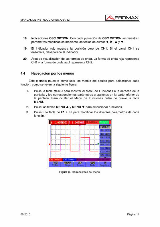
4.4 Navegación por los menús
Este ejemplo muestra cómo usar los menús del equipo para seleccionar cada función, como se ve en la siguiente figura.
1. Pulse la tecla MENU para mostrar el Menú de Funciones a la derecha de la pantalla y los correspondientes parámetros u opciones en la parte inferior de la pantalla. Para ocultar el Menú de Funciones pulse de nuevo la tecla MENU.
2. Pulse las teclas MENU y MENU para seleccionar funciones.
3. Pulse una tecla de F1 a F5 para modificar los diversos parámetros de cada función.
Figura 3.- Herramientas del menú.
MANUAL DE INSTRUCCIONES. OS-782
Página 15 02-2010
4.5 Ajuste manual de los ejes vertical y horizontal y de la posición de
disparo.
Combinando las cuatro teclas “OSC ”, “OSC ”, “OSC ” y “OSC ”, se pueden hacer las configuraciones siguientes pulsando “OSC OPTION”. Las configuraciones incluyen: escala vertical del Canal 1 (CH1 VOL); escala vertical del Canal 2 (CH2 Volts / div); Base de tiempos primaria (Tiempo / div); punto cero del Canal 1 (CH1 CERO); punto cero del Canal 2 (CH2 CERO), posición horizontal de disparo (TIEMPO) y posición del nivel de disparo (TRIG).
El siguiente ejemplo muestra como usar la tecla “OSC OPTION” para hacer ajustes.
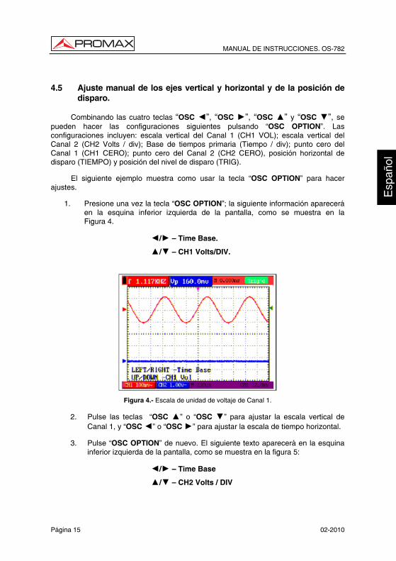
1. Presione una vez la tecla “OSC OPTION”; la siguiente información aparecerá en la esquina inferior izquierda de la pantalla, como se muestra en la Figura 4.
/ — Time Base.
/ — CH1 Volts/DIV.
Figura 4.- Escala de unidad de voltaje de Canal 1.
2. Pulse las teclas “OSC ” o “OSC ” para ajustar la escala vertical de Canal 1, y “OSC ” o “OSC ” para ajustar la escala de tiempo horizontal.
3. Pulse “OSC OPTION” de nuevo. El siguiente texto aparecerá en la esquina inferior izquierda de la pantalla, como se muestra en la figura 5:
/ — Time Base
/ — CH2 Volts / DIV

MANUAL DE INSTRUCCIONES. OS-782
02-2010 Página 16
Figura 5.- Escala de unidad de voltaje de Canal 2.
4. Pulse las teclas “OSC ” o “OSC ” para ajustar la escala vertical de Canal 2, y “OSC ” o “OSC ” para ajustar la escala de tiempo horizontal.
5. Pulse “OSC OPTION” de nuevo. El siguiente texto aparecerá en la esquina
inferior izquierda de la pantalla, como se muestra en la figura 6:
/ — Tiempo
/ — CH1 Cero
Figura 6.- Posición de punto cero del Canal 1.
6. Pulse las teclas “OSC ” o “OSC ” para ajustar la posición Cero del
Canal 1 en la dirección vertical, y “OSC ” o “OSC ” para ajustar la posición horizontal.
7. Pulse “OSC OPTION” de nuevo. El siguiente texto aparecerá en la esquina inferior izquierda de la pantalla, como se muestra en la figura 7:

MANUAL DE INSTRUCCIONES. OS-782
Página 17 02-2010
/ — Tiempo
/ — CH2 Cero
Figura 7.- Posición de punto cero del Canal 2.
8. Pulse las teclas “OSC ” o “OSC ” para ajustar la posición Cero del Canal 2 en la dirección vertical, y “OSC ” o “OSC ” para ajustar la posición horizontal.
9. Pulse “OSC OPTION” de nuevo. El siguiente texto aparecerá en la esquina
inferior izquierda de la pantalla, como se muestra en la figura 8:
/ — Tiempo. / — Trigger.
Figura 8.- Posición del nivel de disparo.
MANUAL DE INSTRUCCIONES. OS-782
02-2010 Página 18
10. Pulse las teclas “OSC ” o “OSC ” para ajustar la posición de disparo del
Canal 2, y “OSC ” o “OSC ” para ajustar la posición horizontal.
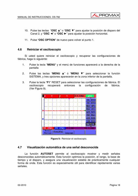
11. Pulse “OSC OPTION” de nuevo para volver al punto 1. 4.6 Reiniciar el osciloscopio
Si usted quiere reiniciar el osciloscopio y recuperar las configuraciones de fábrica, haga lo siguiente:
1. Pulse la tecla "MENU" y el menú de funciones aparecerá a la derecha de la pantalla
2. Pulse las teclas “MENU ” ó “MENU ” para seleccionar la función SISTEMA, y tres opciones aparecerán en la zona inferior de la pantalla.
3. Pulse la tecla "F1" RESET para seleccionar las configuraciones de fábrica. El osciloscopio recuperará entonces la configuración de fábrica. (Ver Figura 9).
Figura 9.- Reiniciar el osciloscopio. 4.7 Visualización automática de una señal desconocida
La función AUTOSET permite al osciloscopio mostrar y medir señales desconocidas automáticamente. Esta función optimiza la posición, el rango, la base de tiempo y el disparo, y asegura una visualización estable de prácticamente cualquier forma de onda. Esta función es especialmente útil para identificar rápidamente varias señales.
MANUAL DE INSTRUCCIONES. OS-782
Página 19 02-2010
Para habilitar la función AUTOSET, haga lo siguiente:
1. Conectar la sonda de prueba a la señal.
2. Pulse la tecla AUTOSET para poner el osciloscopio en modo de medida automática. Las señales adquiridas aparecerán en pantalla.
4.8 Puesta a cero automática de la posición horizontal y el nivel de disparo
Cuando se ajusta la posición horizontal de disparo y la posición de nivel de disparo para ser máxima pantalla, entonces se realizan los siguientes pasos para que la posición horizontal de disparo y la posición de nivel de disparo vuelvan a cero automáticamente:
1. Pulse las teclas “OSC ” y “OSC ” simultáneamente, para que la
posición horizontal de disparo vuelva automáticamente a cero.
2. Pulse las teclas “OSC ” y “OSC ” simultáneamente, para que la
posición de nivel de disparo vuelva automáticamente a cero. 4.9 Medidas automáticas
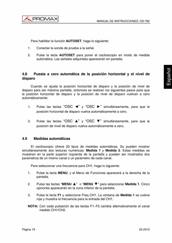
El osciloscopio ofrece 20 tipos de medidas automáticas. Su pueden mostrar simultáneamente dos lecturas numéricas: Medida 1 y Medida 2. Estas medidas se muestran en la parte superior izquierda de la pantalla y pueden ser mostrados dos parámetros de un mismo canal o un parámetro de cada canal.
Para seleccionar una frecuencia para CH1, haga lo siguiente:
1. Pulse la tecla MENU, y el Menú de Funciones aparecerá a la derecha de la pantalla.
2. Pulse las teclas “MENU ” o “MENU ” para seleccionar Medida 1. Cinco opciones aparecerán en la zona inferior de la pantalla.
3. Pulse la tecla F1 y seleccione Freq CH1. La ventana de Medida 1 se vuelve roja y muestra la frecuencia para la entrada del CH1.
NOTA: Con cada pulsación de las teclas F1∼F5 cambia alternativamente el canal medido CH1/CH2.

MANUAL DE INSTRUCCIONES. OS-782
02-2010 Página 20
Para seleccionar una medida de Pico-Pico para CH2, haga lo siguiente:
1. Pulse la tecla MENU, y el Menú de Funciones aparecerá a la derecha de la
pantalla.
2. Pulse las teclas “MENU ” o “MENU ” para seleccionar Medida 2. Cinco opciones aparecerán en la zona inferior de la pantalla.
3. Pulse la tecla F4 para seleccionar Vpp CH2 y realizar una medida de
Pico-Pico. La ventana de Medida 2 se vuelve azul y muestra el valor pico-pico para la entrada del CH2. (Ver Figura 10).
NOTA: Con cada pulsación de las teclas F1∼F5 cambia alternativamente el canal medido CH1 / CH2.
Figura 10.- Medidas automáticas del osciloscopio. 4.10 Congelación de la imagen en pantalla
La imagen en pantalla se puede congelar, con todas las lecturas y formas de onda. Para ello siga los siguientes pasos:
1. Pulse la tecla RUN/STOP para congelar la pantalla. La palabra STOP aparece en esquina superior derecha de la pantalla.
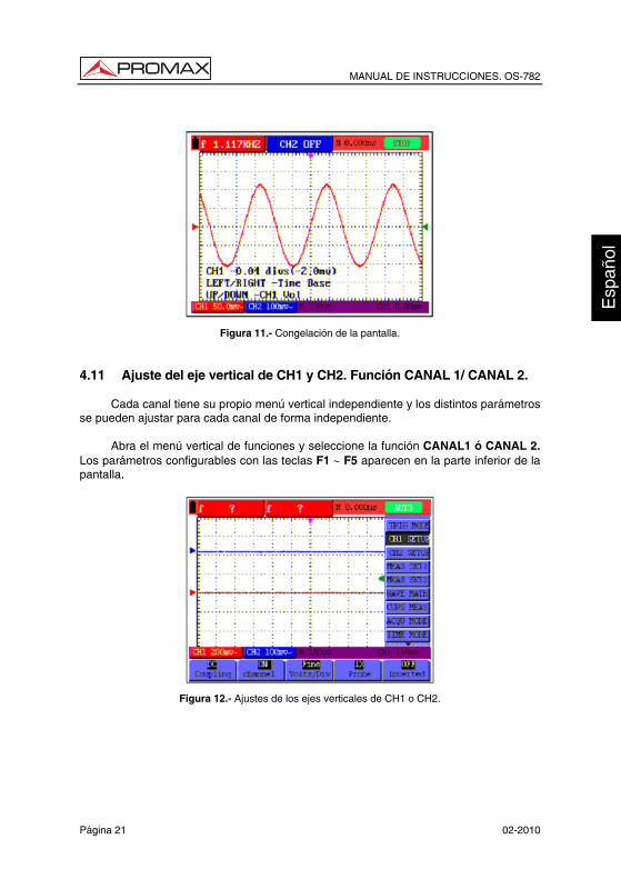
2. Pulse la tecla RUN/STOP una vez más para reanudar su medida. (Ver Figura 11).
MANUAL DE INSTRUCCIONES. OS-782
Página 21 02-2010
Figura 11.- Congelación de la pantalla. 4.11 Ajuste del eje vertical de CH1 y CH2. Función CANAL 1/ CANAL 2.
Cada canal tiene su propio menú vertical independiente y los distintos parámetros se pueden ajustar para cada canal de forma independiente.
Abra el menú vertical de funciones y seleccione la función CANAL1 ó CANAL 2. Los parámetros configurables con las teclas F1 ∼ F5 aparecen en la parte inferior de la pantalla.
Figura 12.- Ajustes de los ejes verticales de CH1 o CH2.

MANUAL DE INSTRUCCIONES. OS-782
02-2010 Página 22
La siguiente tabla describe el menú de ajustes de los ejes verticales del canal:
Menú de función Ajuste Descripción
ACOPLO AC DC Masa
El componente DC de la señal de entrada se bloquea. Los componentes AC y DC de la señal de entrada se permiten.
ACTIVADO Sí No
Activa el canal. Desactiva el canal.
SONDA 1x 10x 100x 1000x
Seleccione un ajuste, según el factor de atenuación de la sonda para asegurar una correcta lectura de la escala vertical.
INVERTIDO No Si
La forma de onda se muestra normalmente. Invierte la señal 180 °
4.11.1 Ajuste del acoplo del canal
Tomando como ejemplo CH1, la señal medida es una señal de onda sinusoidal que contiene un componente DC. Pulse F1 Acoplo y seleccione AC para ajustar acoplamiento AC. El componente DC de la señal quedará bloqueado.
Pulse F1 Acoplo y seleccione DC para ajustar acoplamiento DC. Los componentes CA y DC de la señal quedarán permitidos. (Ver Figuras 13 y 14).
Figura 13.- Acoplamiento de Corriente Alterna.

MANUAL DE INSTRUCCIONES. OS-782
Página 23 02-2010
Figura 14: Acoplamiento de Corriente Continua
4.11.2 Configuración de activación/desactivación del canal
Tomando como ejemplo CH1:
Pulse F2 Activado y seleccione No para desactivar el canal CH1.
Pulse F2 Activado y seleccione Si para activar el canal de CH1. 4.11.3 Ajuste de la escala de sonda
Hay que ajustar el factor de atenuación de la sonda proporcionalmente en el menú de operación del canal, para reflejar la atenuación de la sonda. Si la atenuación de la sonda tiene un factor de 10:1, la escala del canal de entrada del osciloscopio debería ser ajustada a 10x para evitar errores en la información visualizada.
Pulse la tecla F3 Sonda para ir a los ajustes de la sonda que se quiere configurar.
Factor de atenuación de la sonda Ajuste de menú correspondiente 1:1 1x 10:1 10x 100:1 100x 1000:1 1000x
Tabla 1.-: Factor de atenuación de la sonda y el ajuste de menú correspondiente.

MANUAL DE INSTRUCCIONES. OS-782
02-2010 Página 24
4.11.4 Ajuste de forma de onda invertida
Forma de onda invertida: la señal mostrada se invierte 180º grados en relación al potencial de toma de tierra.
Pulse la tecla F4 Invertido para invertir la señal (aparecerá Si); pulse de nuevo F4 Invertido para anular la inversión (aparecerá No). 4.12 Funciones matemáticas “MATH”
La función “MATH” muestra el resultado de sumar, restar, multiplicar o dividir las formas de onda de los canales CH1 y CH2. El resultado de las operaciones aritméticas también se puede medir con la cuadrícula de la pantalla o con el cursor. La amplitud de las formas de onda calculadas se puede ajustar con la tecla pulsando OSC OPTION y modificando el parámetro CHMath Volts/div, que es mostrado en pantalla. La amplitud se extiende de 0.001 a 10, con pasos de 1-2-5, es decir, puede ser expresado como 0.001x, 0.002x, 0.005x…10x. La posición de la forma de onda calculada se puede ajustar arriba y abajo pulsando OSC OPTION y modificado el parámetro CH Math Cero. Tabla de operaciones matemáticas:
Ajuste Descripción CH1-CH2 Forma de onda de CH1 menos forma de onda de CH2. CH2-CH1 Forma de onda de CH2 menos forma de onda de CH1. CH1+CH2 Forma de onda de CH1 mas forma de onda de CH2. CH1*CH2 Forma de onda de CH1 multiplicada por forma de onda de
CH2. CH1/CH2 Forma de onda de CH1 dividida entre forma de onda de CH2.
Para realizar el cálculo de forma de onda CH1+CH2, haga lo siguiente:
1. Pulse la tecla MENU, y el Menú de Funciones aparecerá a la derecha de la
pantalla.
2. Pulse las teclas “MENU ” o “MENU ” para seleccionar MATH. Cinco opciones aparecerán en la zona inferior de la pantalla.
3. Pulse la tecla F3 CH1+CH2 y la forma de onda obtenida aparecerá en pantalla de color verde. Pulse de nuevo F3 para desactivar la forma de onda calculada.

MANUAL DE INSTRUCCIONES. OS-782
Página 25 02-2010
4. Pulse la tecla OSC OPTION y el siguiente texto aparecerá en pantalla:
/ Time Base
/ CHMath Volts/div
5. Pulse las teclas “OSC ” o “OSC ” para ajustar la amplitud de la forma de onda MATH.
6. Pulse la tecla OSC OPTION y el siguiente texto aparecerá en pantalla:
/ Tiempo
/ - CHMATH Cero
7. Pulse las teclas “OSC ” ó “OSC ” para ajustar la posición de la forma de onda MATH. (Ver Figura 15).
Figura 15.- Cálculos matemáticos de forma de onda. 4.13 Ajuste del sistema de disparo. Función TRIGGER
El disparo determina el momento en que el osciloscopio empieza a obtener datos y a presentar una forma de onda. Cuando se configura correctamente un disparo, el osciloscopio convierte las presentaciones inestables o las pantallas en blanco en formas de onda correctamente representadas.
Comenzando la adquisición de datos, el osciloscopio recoge datos suficientes para dibujar la forma de onda a la izquierda del punto de disparo. A la espera de que se den condiciones para el disparo, el osciloscopio recopila datos continuamente. Después de detectar un disparo, el osciloscopio junta suficientes datos para dibujar la forma de onda a la derecha del punto de disparo.

MANUAL DE INSTRUCCIONES. OS-782
02-2010 Página 26
Para ajustar el modo de disparo, haga lo siguiente:
1. Pulse la tecla MENU, y el Menú de Funciones aparecerá a la derecha de la
pantalla.
2. Pulse las teclas “MENU ” o “MENU ” para seleccionar la función TRIGGER. Cinco opciones aparecerán en la zona inferior de la pantalla.
3. Seleccione y pulse una de las teclas de F1 a F5 para realizar diferentes
ajustes.
4. Pulse la tecla OSC OPTION y el siguiente texto aparecerá en pantalla:
/ — Tiempo
/ — Trigger
5. Pulse las teclas “OSC ” o “OSC ” para ajustar la posición del nivel de disparo. (Ver Figura 16).
Figura 16.- Disparo por flanco.
4.14 Control de disparo
Existen dos tipos de disparo disponibles: Por flanco y por vídeo. Hay distintas opciones de ajuste para cada tipo de disparo.
Disparo por flanco: Dispara el osciloscopio cuando el flanco ascendente o de bajada de la señal de entrada cruza el nivel de disparo (umbral).
Disparo por vídeo: Dispara el osciloscopio en líneas o campos de señales de vídeo.

MANUAL DE INSTRUCCIONES. OS-782
Página 27 02-2010
4.14.1 Disparo por Flanco.
La siguiente tabla describe menús de disparo por flanco:
Parámetros Configuraciones Descripción Pendiente Subida
Bajada
Disparo por flanco en la subida de la señal. Disparo por flanco en la bajada de la señal.
Fuente CH1 CH2
CH1 es usado como fuente de disparo. CH2 es usado como fuente de disparo.
1/2
Pasa al siguiente menú.
Bloqueo Pasa al menú de Bloqueo. Modo Auto
Normal Único
La adquisición de formas de onda es posible incluso cuando no se detectan condiciones de disparo. La adquisición de formas de onda sólo se puede efectuar cuando se detectan condiciones de disparo. El muestreo se realiza cuando hay un solo disparo.
Acoplo AC (Corriente alterna) DC (Corriente continua) Rechazo AF Supresión de la alta frecuencia Rechazo BF Supresión de la baja frecuencia
Bloquea los componentes de la DC. Pasan todos los componentes de la señal. La parte de alta frecuencia de de la señal se bloquea y sólo se permite el componente de baja frecuencia. La parte de baja frecuencia de de la señal se bloquea y sólo se permite el componente de alta frecuencia.
2/2
Vuelve al menú anterior.
Conceptos básicos
Modos de disparo: Hay tres modos de disparo disponibles para este osciloscopio que son automático, normal y disparo único.
1.- Modo de disparo automático: El osciloscopio puede adquirir la forma de onda sin que
se detecten condiciones de disparo. En este modo el disparo será provocado periódicamente si durante un período especificado del tiempo no se han dado condiciones de disparo.

MANUAL DE INSTRUCCIONES. OS-782
02-2010 Página 28
2.- Modo de disparo
normal: En este modo, el osciloscopio no puede adquirir la forma de onda si no se provoca un disparo. Cuando no hay un disparo, el osciloscopio mostrará la forma de onda de origen sin actualizar.
3.- Disparo único: En este modo, el osciloscopio detecta el disparo y
adquiera una forma de onda cada vez que el usuario pulsa la tecla RUN/STOP.
4.14.2 Menús de disparo por video
En modo de disparo por video, el osciloscopio muestra formas de onda de vídeo compuesto en estándar NTSC o PAL/SECAM. Se dispara en líneas, campos pares, campos impares o por número de línea de señal de video. (Ver Figuras 17 y 18).
Figura 17.- Disparo en campo de señal de vídeo.
Figura 18.- Disparo en línea de señal de vídeo

MANUAL DE INSTRUCCIONES. OS-782
Página 29 02-2010
La siguiente tabla describe los menús de disparo por video:
Parámetros Configuraciones Descripción Polaridad Normal
Invertida
Aplicable a la señal de vídeo en la cual el nivel negro es el nivel bajo. Aplicable a la señal de vídeo en la cual el nivel negro es el nivel alto.
Fuente CH1 CH2
CH1 es usado como fuente de disparo. CH2 es usado como fuente de disparo.
Sinc Línea Cuadro Odd field Even field Line NO
Sincroniza el disparo en línea de señal de vídeo Sincroniza el disparo en cuadro de señal de vídeo Sincroniza el disparo en cuadro impar de señal de vídeo. Sincroniza el disparo en cuadro par de señal de vídeo. Sincroniza el disparo en la línea seleccionada de señal de vídeo.
1/2
Pasa al siguiente menú.
El menú de disparo por vídeo (segunda página):
1. Cuando la sincronización es del tipo línea, cuadro, cuadro impar (Odd field) o cuadro par (Even field), la segunda página de menú se muestra tal como sigue:
Formato NTSC/PAL/SECAM Configuración formato vídeo
Bloqueo Pasa al menú de bloqueo 2/2
Vuelve al menú anterior
2. Cuando la sincronización es del tipo línea seleccionada (Line No) la segunda
página de menú se muestra tal como sigue:
Formato NTSC/PAL/SECAM Configuración formato vídeo Línea Incrementar
Decrementar Incrementa el valor de la línea Decrementa el valor de la línea
Línea No. Muestra y ajusta el número de línea. Bloqueo. Pasa al menú de bloqueo. 2/2
Vuelve al menú anterior.
MANUAL DE INSTRUCCIONES. OS-782
02-2010 Página 30
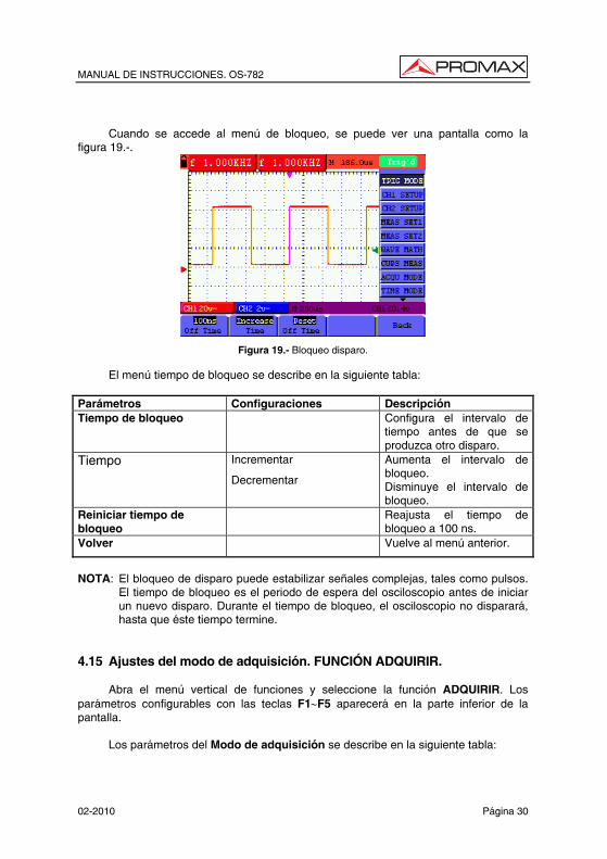
Cuando se accede al menú de bloqueo, se puede ver una pantalla como la
figura 19.-.
Figura 19.- Bloqueo disparo.
El menú tiempo de bloqueo se describe en la siguiente tabla: Parámetros Configuraciones Descripción Tiempo de bloqueo Configura el intervalo de
tiempo antes de que se produzca otro disparo.
Tiempo Incrementar
Decrementar
Aumenta el intervalo de bloqueo. Disminuye el intervalo de bloqueo.
Reiniciar tiempo de bloqueo
Reajusta el tiempo de bloqueo a 100 ns.
Volver Vuelve al menú anterior.
NOTA: El bloqueo de disparo puede estabilizar señales complejas, tales como pulsos.
El tiempo de bloqueo es el periodo de espera del osciloscopio antes de iniciar un nuevo disparo. Durante el tiempo de bloqueo, el osciloscopio no disparará, hasta que éste tiempo termine.
4.15 Ajustes del modo de adquisición. FUNCIÓN ADQUIRIR.
Abra el menú vertical de funciones y seleccione la función ADQUIRIR. Los parámetros configurables con las teclas F1∼F5 aparecerá en la parte inferior de la pantalla.
Los parámetros del Modo de adquisición se describe en la siguiente tabla:

MANUAL DE INSTRUCCIONES. OS-782
Página 31 02-2010
Parámetros Configuraciones Descripción Muestreo Modo de muestreo normal. Detección de pico
Se usa para descubrir problemas técnicos y reducir los posibles errores.
Promedio Se usa para reducir ruidos arbitrarios. Se pueden seleccionar varios factores promedios.
Factor promedio
4, 16, 64 o 128 Selección del factor promedio.
4.16 Ajustes de pantalla. Función DISPLAY.
Abra el menú vertical de funciones y seleccione la función DISPLAY. Los parámetros configurables con las teclas F1∼F5 aparecerá en la parte inferior de la pantalla.
El menú de Ajustes de pantalla se describe en la siguiente tabla:
Parámetros Configuraciones Descripción Tipo Vectores
Puntos
Se rellena el espacio entre puntos de muestra adyacentes en la pantalla. Se visualizan sólo los puntos de muestra.
Persistencia No 1s 2s 5s Infinito
Establece la cantidad de tiempo que cada punto de muestra permanece en pantalla.
Formato YT XY
El formato YT muestra el voltaje vertical con relación al tiempo (escala horizontal). Muestra el CH1 en el eje horizontal y CH2 en el eje vertical.
Gráfico Bitmap (Mapa de bits) Vectorial
Los datos transmitidos en la comunicación son mapas de bits. Los datos transmitidos en la comunicación son vectores.
4.16.1 Estilo de visualización
El estilo de visualización incluye visualizaciones de modo Vectores y Puntos, como se puede ver en las Figuras 20 y 21:

MANUAL DE INSTRUCCIONES. OS-782
02-2010 Página 32
Figura 20.- Modo de puntos.
Figura 21.- Modo de vector. 4.16.2 Persistencia
Seleccionando la función Persistencia, los datos originales mostrados pierden gradualmente color, mientras que los nuevos datos aparecen en pantalla en colores más brillantes; con el modo Persistencia Infinita seleccionado, los puntos registrados se mantendrán en pantalla hasta que el valor establecido cambie. 4.16.3 Modo XY
Este modo sólo es aplicable con los canales CH1 y CH2 activados. Con el modo XY seleccionado, CH1 se muestra en el eje horizontal y CH2 en el eje vertical. Cuando el osciloscopio está en modo de muestreo en el que no hay ningún disparo, los datos aparecen en puntos más claros.

MANUAL DE INSTRUCCIONES. OS-782
Página 33 02-2010
Funciones OSC OPTION:
• Las funciones CH1 Volts/div y CH1 Cero para CH1 se utilizan para fijar la posición y la escala horizontales.
• Las funciones CH2 Volts/div y CH2 Cero para CH2 se utilizan para
fijar la posición y la escala verticales. Las siguientes funciones no son operativas en el modo de visualización de XY:
• Forma de onda de referencia o de valor digital.
• Cursor.
• Ajuste automático.
• Control de bases de tiempo.
• Control de disparo.
4.17 Ajustes para guardar las formas de onda. Función MEMORIA.
El osciloscopio puede guardar hasta 4 formas de onda, que se pueden mostrar en pantalla con la forma de onda actual. Las formas de onda memorizadas no se pueden modificar.
El menú de Memorizar/Recuperar formas de onda se describe en la siguiente tabla:
Parámetros Configuraciones Descripción Fuente CH1
CH2 MATH
Selecciona la forma de onda visualizada que se quiere memorizar.
Onda A, B, C, D Selecciona la dirección para guardar o recuperar una forma de onda.
Guardar Almacena la forma de onda de una fuente de señal seleccionada en la dirección seleccionada.
Mostrar No / Si Cierra o inicia la visualización de las formas de onda memorizadas en las direcciones A, B, C, D.
Para guardar una forma de onda en CH1 en la dirección A, haga lo siguiente:
1. Pulse la tecla MENU, y el Menú de Funciones aparecerá a la derecha de la
pantalla.
2. Pulse las teclas “MENU ” o “MENU ” para seleccionar MEMORIA. Cuatro opciones aparecerán en la zona inferior de la pantalla.
3. Pulse la tecla F1 para seleccionar la fuente de señal de CH1.

MANUAL DE INSTRUCCIONES. OS-782
02-2010 Página 34
4. Pulse la tecla F2 para seleccionar la dirección A.
5. Pulse la tecla F3 para guardar la forma de onda de CH1 en la dirección A.
Para visualizar la forma de onda memorizada, haga lo siguiente:
6. Pulse la tecla F4 para seleccionar Si para la dirección A. La forma de onda guardada en la dirección A se mostrará en pantalla en color verde.
El color de visualización es verde, y el punto cero de la forma de onda k, el voltaje y el tiempo son de color violeta. (Ver Figura 22).
Figura 22.- Memorización de formas de onda.
4.18 Menú de Sistema. Función SISTEMA
Abra el menú vertical de funciones y seleccione la función SISTEMA. Los parámetros configurables con las teclas F1∼F5 aparecerán en la parte inferior de la pantalla.
Los parámetros de Configuración se describe en la siguiente tabla:
Parámetros Configuraciones Descripción RESET Recupera las configuraciones de fábrica. AUTOCALIBRAR Realiza autocalibración del equipo. Idiomas ESPAÑOL
INGLÉS Selecciona el idioma de visualización del sistema.
MANUAL DE INSTRUCCIONES. OS-782
Página 35 02-2010
Autocalibración:
El programa de autocalibración puede mejorar la exactitud del osciloscopio a temperatura ambiental al máximo. Si la variación de temperatura ambiente es igual o mayor de 5 °C, el programa de autocorrección se activa para lograr la máxima exactitud.
Antes de activar el programa de autocorrección, hay que desconectar la sonda y los cables del conector de entrada. Después de confirmar que todo está listo, pulse la tecla F2 y seleccione "Autocalibración" para activar el programa de autocorrección.
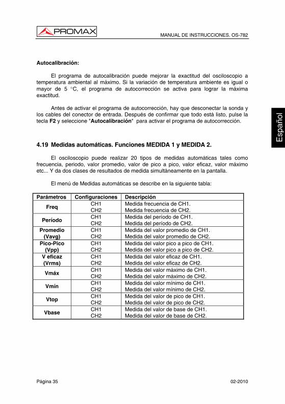
4.19 Medidas automáticas. Funciones MEDIDA 1 y MEDIDA 2.
El osciloscopio puede realizar 20 tipos de medidas automáticas tales como frecuencia, periodo, valor promedio, valor de pico a pico, valor eficaz, valor máximo etc... Y da dos clases de resultados de medida simultáneamente en la pantalla.
El menú de Medidas automáticas se describe en la siguiente tabla: Parámetros Configuraciones Descripción
Freq CH1 CH2
Medida frecuencia de CH1. Medida frecuencia de CH2.
Período CH1 CH2
Medida del período de CH1. Medida del período de CH2.
Promedio (Vavg)
CH1 CH2
Medida del valor promedio de CH1. Medida del valor promedio de CH2.
Pico-Pico (Vpp)
CH1 CH2
Medida del valor pico a pico de CH1. Medida del valor pico a pico de CH2.
V eficaz (Vrms)
CH1 CH2
Medida del valor eficaz de CH1. Medida del valor eficaz de CH2.
Vmáx CH1 CH2
Medida del valor máximo de CH1. Medida del valor máximo de CH2.
Vmín CH1 CH2
Medida del valor mínimo de CH1. Medida del valor mínimo de CH2.
Vtop CH1 CH2
Medida del valor de pico de CH1. Medida del valor de pico de CH2.
Vbase CH1 CH2
Medida del valor de base de CH1. Medida del valor de base de CH2.
MANUAL DE INSTRUCCIONES. OS-782
02-2010 Página 36
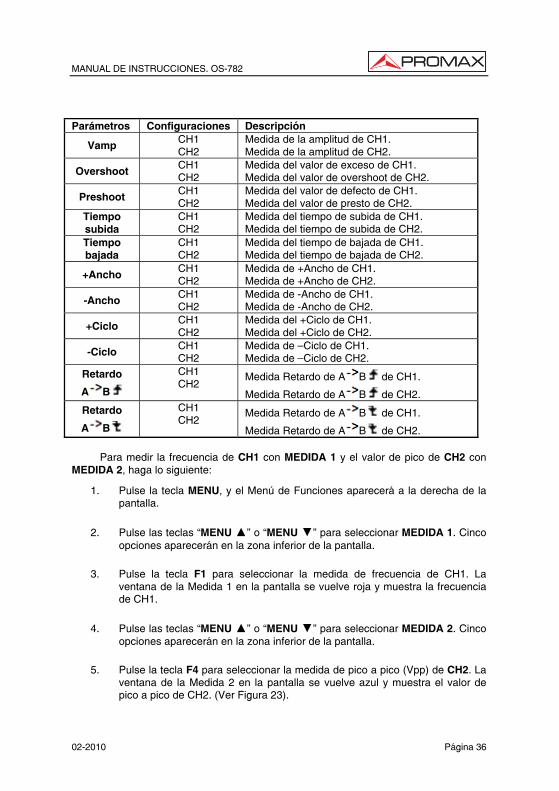
Parámetros Configuraciones Descripción
Vamp CH1 CH2
Medida de la amplitud de CH1. Medida de la amplitud de CH2.
Overshoot CH1 CH2
Medida del valor de exceso de CH1. Medida del valor de overshoot de CH2.
Preshoot CH1 CH2
Medida del valor de defecto de CH1. Medida del valor de presto de CH2.
Tiempo subida
CH1 CH2
Medida del tiempo de subida de CH1. Medida del tiempo de subida de CH2.
Tiempo bajada
CH1 CH2
Medida del tiempo de bajada de CH1. Medida del tiempo de bajada de CH2.
+Ancho CH1 CH2
Medida de +Ancho de CH1. Medida de +Ancho de CH2.
-Ancho CH1 CH2
Medida de -Ancho de CH1. Medida de -Ancho de CH2.
+Ciclo CH1 CH2
Medida del +Ciclo de CH1. Medida del +Ciclo de CH2.
-Ciclo CH1 CH2
Medida de —Ciclo de CH1. Medida de —Ciclo de CH2.
Retardo
A B
CH1 CH2
Medida Retardo de A B de CH1.
Medida Retardo de A B de CH2.
Retardo
A B
CH1 CH2
Medida Retardo de A B de CH1.
Medida Retardo de A B de CH2.
Para medir la frecuencia de CH1 con MEDIDA 1 y el valor de pico de CH2 con MEDIDA 2, haga lo siguiente:
1. Pulse la tecla MENU, y el Menú de Funciones aparecerá a la derecha de la pantalla.
2. Pulse las teclas “MENU ” o “MENU ” para seleccionar MEDIDA 1. Cinco opciones aparecerán en la zona inferior de la pantalla.
3. Pulse la tecla F1 para seleccionar la medida de frecuencia de CH1. La ventana de la Medida 1 en la pantalla se vuelve roja y muestra la frecuencia de CH1.
4. Pulse las teclas “MENU ” o “MENU ” para seleccionar MEDIDA 2. Cinco opciones aparecerán en la zona inferior de la pantalla.
5. Pulse la tecla F4 para seleccionar la medida de pico a pico (Vpp) de CH2. La ventana de la Medida 2 en la pantalla se vuelve azul y muestra el valor de pico a pico de CH2. (Ver Figura 23).

MANUAL DE INSTRUCCIONES. OS-782
Página 37 02-2010
Ahora se puede ver una pantalla parecida a la siguiente figura.
Figura 23.-: Medidas automáticas.
Definición de conceptos
Vpp: Voltaje de Pico a Pico.
Vmáx: Amplitud máxima. El voltaje de pico más positivo medido sobre la señal entera.
Vmín: Amplitud mínima. El voltaje de pico más negativo medido sobre la señal entera.
Vamp: Voltaje entre Vtop y Vbase de una señal.
Vtop: Voltaje en cumbre plana de la señal. Útil para señales cuadradas y pulsos.
Vbase: Voltaje en base de la señal. Útil para señales cuadradas y pulsos.
Over shoot: Se define como la tensión de pico post-Flanco de subida. Útil para señales cuadradas y pulsos.
Pre shoot: Se define como la tensión de pico pre-Flanco de subida. Útil para señales cuadradas y pulsos.
Vavg Promedio: La media aritmética de la señal completa.
Vrms Vef: El valor absoluto de la raíz cuadrada del voltaje de la señal.
Tiempo subida: Tiempo en el que el flanco de subida de la señal crece de 10% a 90% de su amplitud.
Tiempo de bajada: Tiempo en el que el flanco de bajada de la señal pasa de 90% a 10% de su amplitud.
+Ancho: El ancho del primer pulso positivo en el 50% de los puntos de amplitud.
MANUAL DE INSTRUCCIONES. OS-782
02-2010 Página 38
NOTA: En el manual del OD-590 hay unos dibujos que representan muy bien el significado de cada medida.
-Ancho: El ancho del primer pulso negativo en el 50% de los puntos de amplitud.
Retraso 1 → 2 : El retardo entre los dos canales en el flanco de subida.
Retraso 1 → 2 : El retardo entre dos canales en el flanco de bajada.
+Ciclo: + Ciclo de trabajo, definido como +Ancho / período.
-Ciclo: - Ciclo de trabajo, definido como —Ancho / Período.
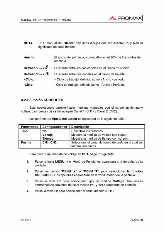
4.20 Función CURSORES
Este osciloscopio permite hacer medidas manuales con el cursor en tiempo y voltaje. Las fuentes de señal incluyen Canal 1 (CH1) y Canal 2 (CH2).
Los parámetros Ajuste del cursor se describen en la siguiente tabla: Parámetros Configuraciones Descripción Tipo No
Voltaje Tiempo
Desactiva los cursores. Muestra la medida de voltaje con cursor. Muestra la medida de tiempo con cursor.
Fuente CH1, CH2 Selecciona el canal de forma de onda en el cual se medirá con cursor.
Para hacer una medida de voltaje en CH1, haga lo siguiente:
1. Pulse la tecla MENU, y el Menú de Funciones aparecerá a la derecha de la
pantalla.
2. Pulse las teclas “MENU ” o “MENU ” para seleccionar la función CURSORES. Dos opciones aparecerán en la zona inferior de la pantalla.
3. Pulse la tecla F1 para seleccionar tipo de medida Voltage. Dos líneas interrumpidas cruzadas de color violeta (V1 y V2) aparecerán en pantalla.
4. Pulse la tecla F2 para seleccionar el canal medido (CH1).
MANUAL DE INSTRUCCIONES. OS-782
Página 39 02-2010
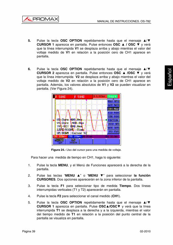
5. Pulse la tecla OSC OPTION repetidamente hasta que el mensaje / CURSOR 1 aparezca en pantalla. Pulse entonces OSC / OSC y verá que la línea interrumpida V1 se desplaza arriba y abajo mientras el valor del voltaje medido de V1 en relación a la posición cero de CH1 aparece en pantalla.
6. Pulse la tecla OSC OPTION repetidamente hasta que el mensaje / CURSOR 2 aparezca en pantalla. Pulse entonces OSC /OSC y verá que la línea interrumpida V2 se desplaza arriba y abajo mientras el valor del voltaje medido de V2 en relación a la posición cero de CH1 aparece en pantalla. Además, los valores absolutos de V1 y V2 se pueden visualizar en pantalla. (Ver Figura 24).
Figura 24.- Uso del cursor para una medida de voltaje.
Para hacer una medida de tiempo en CH1, haga lo siguiente:
1. Pulse la tecla MENU, y el Menú de Funciones aparecerá a la derecha de la pantalla.
2. Pulse las teclas “MENU ” o “MENU ” para seleccionar la función CURSORES. Dos opciones aparecerán en la zona inferior de la pantalla.
3. Pulse la tecla F1 para seleccionar tipo de medida Tiempo. Dos líneas interrumpidas verticales (T1 y T2) aparecerán en pantalla.
4. Pulse la tecla F2 para seleccionar el canal medido (CH1).
5. Pulse la tecla OSC OPTION repetidamente hasta que el mensaje / CURSOR 1 aparezca en pantalla. Pulse OSC/OSC y verá que la línea interrumpida T1 se desplaza a la derecha y a la izquierda, mientras el valor del tiempo medido de T1 en relación a la posición del punto central de la pantalla se visualiza en pantalla.

MANUAL DE INSTRUCCIONES. OS-782
02-2010 Página 40
6. Pulse la tecla OSC OPTION repetidamente hasta que el mensaje / CURSOR 2 aparezca en pantalla. Pulse entonces OSC /OSC y verá que la línea interrumpida T2 se desplaza a la derecha y a la izquierda, mientras el valor del tiempo medido de T1 en relación a la posición del punto central de la pantalla se visualiza en pantalla. También se pueden ver los valores de tiempo absolutos y las frecuencias de T1 y T2. (Ver Figura 25).
Figura 25.- Uso del cursor para una medida de tiempo.
4.21 Auto-Escala
Esta función realiza un seguimiento de las señales de forma automática, incluso cuando las señales cambian constantemente. La función Auto-escala permite al instrumento ajustar el modo de disparo, la división de voltaje y la escala de tiempo de forma automática según el tipo, amplitud y frecuencia de las señales.
El menú es el siguiente: Parámetros Configuraciones Descripción
Auto-escala
OFF
ON
Desactiva Auto-escala.
Activa Auto-escala.
Modo
Vertical
Horizontal
HOR - VERT
Seguimiento y ajuste de la escala vertical sin
afectar al ajuste horizontal.
Seguimiento y ajuste de la escala horizontal sin
afectar al ajuste vertical.
Seguimiento y ajuste de la escala horizontal y vertical.
Sólo muestra uno o dos períodos.
Muestra señales multi-período.

MANUAL DE INSTRUCCIONES. OS-782
Página 41 02-2010
Si se desea medir el voltaje del CANAL 1, se han de seguir los siguientes pasos:
1. Pulse MENU y el menú de opciones aparecerá en el lado derecho de la pantalla.
2. Pulse MENU o MENU y seleccione Auto-escala, aparecerán tres opciones en la parte inferior de la pantalla.
3. Pulse F1 y seleccione ON.
4. Pulse F2 y seleccione Hori - Vert.
5. Pulse F3 y se mostrará en la pantalla como en la siguiente figura:
Figure 26.- Auto-Escala Horizontal-Vertical multi-período.
Figure 27.- Auto-Escale Horizontal-Vertical mono-período.
MANUAL DE INSTRUCCIONES. OS-782
02-2010 Página 42
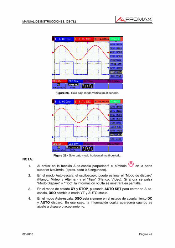
Figure 28.- Sólo bajo modo vertical multiperiodo.
Figure 29.- Sólo bajo modo horizontal multi-periodo.
NOTA:
1. Al entrar en la función Auto-escala parpadeará el símbolo en la parte superior izquierda. (aprox. cada 0,5 segundos).
2. En el modo Auto-escala, el osciloscopio puede estimar el “Modo de disparo” (Flanco, Vídeo y Alternar) y el “Tipo” (Flanco, Vídeo). Si ahora se pulsa “Modo Disparo” o “Tipo”, la información oculta se mostrará en pantalla.
3. En el modo de estado XY y STOP, pulsando AUTO SET para entrar en Auto-escala, DSO cambia a modo YT y AUTO status.
4. En el modo Auto-escala, DSO está siempre en el estado de acoplamiento DC y AUTO disparo. En ese caso, la información oculta aparecerá cuando se ajuste a disparo o acoplamiento.
MANUAL DE INSTRUCCIONES. OS-782
Página 43 02-2010
5. En el modo Auto-escala, si se ajusta la posición vertical, la división de voltaje,
el nivel de disparo o la escala de tiempo de CH1 o CH2, el osciloscopio desactivará la función Auto-escala y si pulsa AUTOSET de nuevo, el osciloscopio entra en modo Auto-escala.
6. Desactive el submenú en el menú Auto-escala. Cuando la Auto-escala está apagada, active el submenú entrando en la función.
7. Cuando se dispara en modo vídeo, la escala horizontal es 50 µs. Si un canal está mostrando una señal de flanco y el otro canal está una señal de vídeo, la escala de tiempo se refiere a 50us tanto a la señal de video como al flanco.
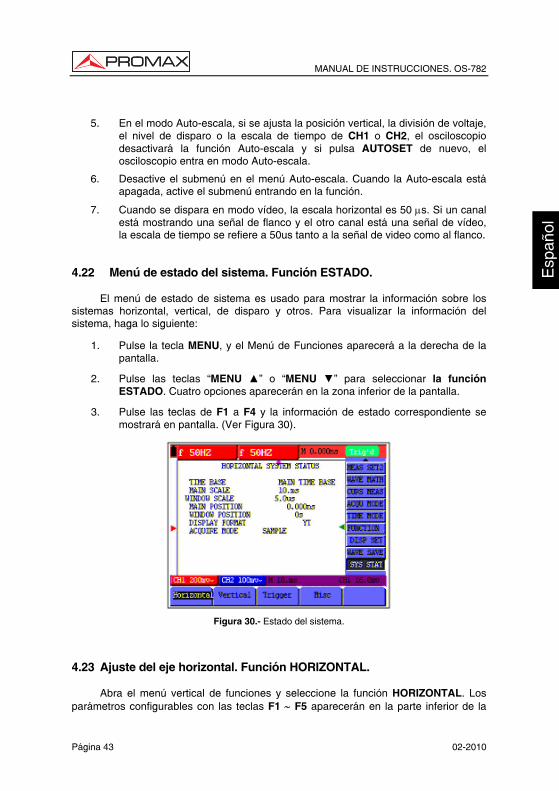
4.22 Menú de estado del sistema. Función ESTADO.
El menú de estado de sistema es usado para mostrar la información sobre los sistemas horizontal, vertical, de disparo y otros. Para visualizar la información del sistema, haga lo siguiente:
1. Pulse la tecla MENU, y el Menú de Funciones aparecerá a la derecha de la pantalla.
2. Pulse las teclas “MENU ” o “MENU ” para seleccionar la función ESTADO. Cuatro opciones aparecerán en la zona inferior de la pantalla.
3. Pulse las teclas de F1 a F4 y la información de estado correspondiente se mostrará en pantalla. (Ver Figura 30).
Figura 30.- Estado del sistema.
4.23 Ajuste del eje horizontal. Función HORIZONTAL.
Abra el menú vertical de funciones y seleccione la función HORIZONTAL. Los parámetros configurables con las teclas F1 ∼ F5 aparecerán en la parte inferior de la

MANUAL DE INSTRUCCIONES. OS-782
02-2010 Página 44
pantalla.
El menú HORIZONTAL se describe en la siguiente tabla: Parámetros Configuraciones Descripción Principal La principal base de tiempo horizontal se usa
para la visualización de ondas. Ventana Usa dos cursores para definir un área de
ventana. Zoom ventana
Amplía la ventana definida a la visualización de pantalla completa.
Para realizar una ampliación de ventana, siga los pasos siguientes:
1. Pulse la tecla MENU, y el Menú de Funciones aparecerá a la derecha de la
pantalla.
2. Pulse las teclas “MENU ” o “MENU ” para seleccionar HORIZONTAL. Tres opciones aparecerán en la zona inferior de la pantalla.
3. Pulse tecla F3 para seleccionar Ventana.
4. Pulse la tecla OSC OPTION, seleccione Time Base, y pulse OSC / OSC para ajustar el área de la ventana de base de tiempos definida por los dos cursores. El tamaño de ventana cambiará.
5. Pulse la tecla OSC OPTION, seleccione Tiempo y pulse OSC / OSC para ajustar la posición de la ventana definida por los dos cursores. La posición de la ventana es la diferencia de tiempo del centro de la ventana al indicador horizontal de la base de tiempo principal.
6. Pulse la tecla F2 para seleccionar Zoom Ventana, y la ventana definida aumentará a modo de pantalla completa.
Ver Figuras 31 y 32.

MANUAL DE INSTRUCCIONES. OS-782
Página 45 02-2010
Figura 31.- Ajuste de ventana.
Figura 32.- Extensión de ventana.
4.24 Transmisión de datos al PC
El osciloscopio OS-782 dispone de un puerto USB que permite transmitir los datos mostrados y/o memorizados de el equipo al ordenador.
Con el equipo se adjunta un CD con el programa de comunicación. Para su instalación siga los siguientes pasos.
1. Inserte el CD en el lector de discos.
2. Abra el explorador y ejecute el fichero Setup.exe y siga las instrucciones del instalador. Por defecto el programa se instala en la carpeta c\Archivos de programa\PROMAX\OS-Wave\Oscilloscope\. Acceda al menú Help del programa para cualquier consulta.

MANUAL DE INSTRUCCIONES. OS-782
02-2010 Página 46
3. Una vez instalado, conecte el cable USB entre el equipo y el PC. Encienda el equipo. Automáticamente el PC detectara un nuevo equipo y le pedirá de instalar el driver correspondiente.
4. Seleccione el método avanzado de instalación y en la siguiente pantalla seleccione la carpeta USBDRV que hay dentro del directorio donde se ha instalado el programa. Pulse “Siguiente” para instalar el driver.
5. Ahora ya puede abrir el programa DS Wave para la captura de datos en el PC.

MANUAL DE INSTRUCCIONES. OS-782
Página 47 02-2010
5. UTILIZACIÓN DEL MULTÍMETRO 5.1 Sobre este capítulo
Este capítulo es una explicación paso a paso a las funciones del multímetro del equipo. La introducción da ejemplos para mostrar cómo usar los menús y realizar operaciones básicas. 5.2 Conexiones del multímetro
Use las tres entradas de seguridad tipo banana COM, V/Ω y mA para medición de voltaje, resistencia y corriente, y las dos cuadrangulares CX para medir capacitancia. (Véase la Figura 1). 5.3 Pantalla del multímetro
Figura 33.-
Descripción
1.- Indicador del estado de carga de la batería.
2.- Indicadores de rango MANUAL/AUTO. MANUAL indica el rango de medida en modo de operación manual y AUTOMÁTICO indica el rango de medida en modo de operación automático.
MANUAL DE INSTRUCCIONES. OS-782
02-2010 Página 48
3.- Indicadores de modo de medida:
DCV: medida de voltaje en continua.
ACV: medida de voltaje en alterna.
DCA: medida de corriente en continua.
ACA: medida de corriente en alterna.
R: medida de resistencia
: medida de diodo.
: Medida con./desc.
C: medida de capacitancia
4.- Indicador de medida de magnitud relativa.
5.- Indicador del estado de actualización de la pantalla. RUN indica estado de medición continua y STOP indica congelación del último valor medido.
6.- Valor de referencia de la medida de magnitud relativa.
7.- Factor de multiplicación de la escala de medida. Multiplicándolo por la lectura de la escala de medida, se obtendrá el resultado de la medida.
8.- Unidad y valor de medida.
9.- Control automático del rango de medida. Se activa pulsando F3.
10.- Control de medida de magnitud Absoluta / Relativa: el símbolo “||” expresa una magnitud absoluta y "∆" una magnitud relativa. Control de medida manual.
11.- Control manual del rango de medida.
12.- Escala analógica de medida. Muestra el rango de medidas en el que se está trabajando. Cada modo de test se presenta en un color diferente.
5.4 Medir con el multímetro
Pulsando la tecla DMM/OSC, el osciloscopio cambiará a modo de multímetro. La pantalla mostrará la ventana del multímetro y al mismo tiempo solicitara que se inserten correctamente las puntas de prueba. A continuación pulse cualquier tecla para entrar en el modo de medición.
MANUAL DE INSTRUCCIONES. OS-782
Página 49 02-2010
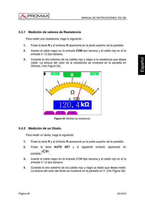
5.4.1 Medición de valores de Resistencia
Para medir una resistencia, haga lo siguiente:
1. Pulse la tecla R y el símbolo R aparecerá en la parte superior de la pantalla.
2. Inserte el cable negro en la entrada COM tipo banana y el cable rojo en el la entrada V / Ω tipo banana.
3. Conecte el otro extremo de los cables rojo y negro a la resistencia que desea medir. La lectura del valor de la resistencia se mostrará en la pantalla en Ohmios. (Ver Figura 34).
Figura 34: Medida de resistencia. 5.4.2 Medición de un Diodo.
Para medir un diodo, haga lo siguiente:
1. Pulse la tecla R y el símbolo R aparecerá en la parte superior de la pantalla.
2. Pulse la tecla AUTO SET y el siguiente símbolo aparecerá en
pantalla .
3. Inserte el cable negro en la entrada COM tipo banana y el cable rojo en el la entrada V / Ω tipo banana.
4. Conecte el otro extremo de los cables rojo y negro al diodo que desea medir. La lectura del valor del diodo se mostrará en la pantalla en V. (Ver Figura 35).

MANUAL DE INSTRUCCIONES. OS-782
02-2010 Página 50
Figura 35.- Medida de diodo.
5.4.3 Prueba continuidad.
Para hacer una prueba de continuidad, haga lo siguiente:
1. Pulse la tecla R y el símbolo R aparecerá en la parte superior de la pantalla.
2. Pulse repetidamente la tecla AUTO SET hasta que el siguiente símbolo
aparezca en pantalla .
3. Inserte el cable negro en la entrada COM tipo banana y el cable rojo en el la entrada V / Ω tipo banana.
4. Conecte el otro extremo de los cables rojo y negro al punto de prueba. Si el valor de la resistencia del punto de prueba es menor de 50 Ω, el multímetro emitirá un pitido. (Ver Figura 36).
Figura 36: Prueba de funcionamiento

MANUAL DE INSTRUCCIONES. OS-782
Página 51 02-2010
5.4.4 Medición de una Capacitancia
Para medir una capacitancia, haga lo siguiente:
1. Pulse la tecla R y el símbolo R aparecerá en la parte superior de la pantalla.
2. Pulse repetidamente la tecla AUTO SET hasta que el símbolo C aparezca en la zona superior de la pantalla.
3. Inserte la capacitancia en la entrada cuadrangular o use las puntas de prueba conectadas a los terminales COM y V/Ω, y la pantalla mostrará la lectura de la capacitancia.
NOTA: Cuando el valor de la capacitancia es menor de 5 nF, por favor use el adaptador para pequeña capacitancia de este multímetro, y el modo de medida de valor relativo para mejorar la precisión de medición. Esta operación tardará aproximadamente 30 segundos si la medida de capacitancia es mayor de 40uF.
(Ver Figura 37).
Figura 37.- Medida de capacitancia
MANUAL DE INSTRUCCIONES. OS-782
02-2010 Página 52
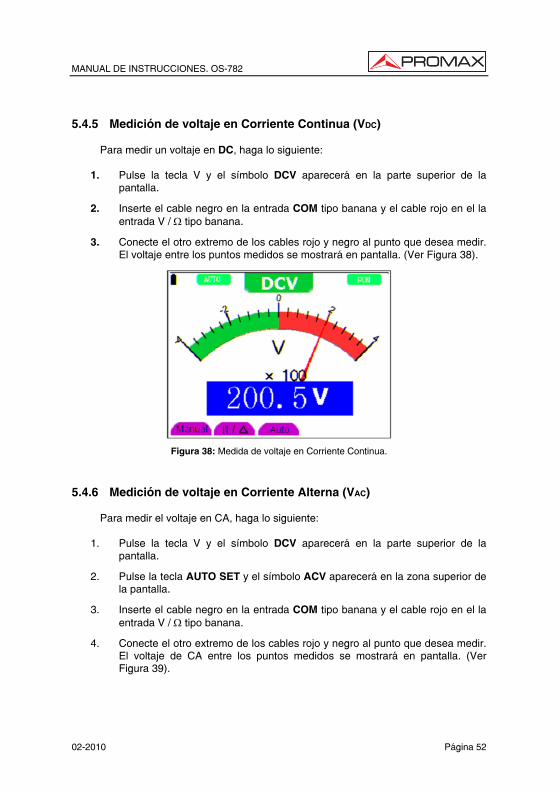
5.4.5 Medición de voltaje en Corriente Continua (VDC)
Para medir un voltaje en DC, haga lo siguiente:
1. Pulse la tecla V y el símbolo DCV aparecerá en la parte superior de la pantalla.
2. Inserte el cable negro en la entrada COM tipo banana y el cable rojo en el la entrada V / Ω tipo banana.
3. Conecte el otro extremo de los cables rojo y negro al punto que desea medir. El voltaje entre los puntos medidos se mostrará en pantalla. (Ver Figura 38).
Figura 38: Medida de voltaje en Corriente Continua.
5.4.6 Medición de voltaje en Corriente Alterna (VAC)
Para medir el voltaje en CA, haga lo siguiente:
1. Pulse la tecla V y el símbolo DCV aparecerá en la parte superior de la pantalla.
2. Pulse la tecla AUTO SET y el símbolo ACV aparecerá en la zona superior de la pantalla.
3. Inserte el cable negro en la entrada COM tipo banana y el cable rojo en el la entrada V / Ω tipo banana.
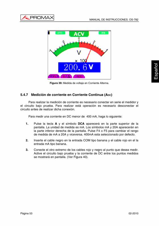
4. Conecte el otro extremo de los cables rojo y negro al punto que desea medir. El voltaje de CA entre los puntos medidos se mostrará en pantalla. (Ver Figura 39).
MANUAL DE INSTRUCCIONES. OS-782
Página 53 02-2010
Figura 39: Medida de voltaje en Corriente Alterna.
5.4.7 Medición de corriente en Corriente Continua (ADC)
Para realizar la medición de corriente es necesario conectar en serie el medidor y el circuito bajo prueba. Para realizar está operación es necesario desconectar el circuito antes de realizar dicha conexión.
Para medir una corriente en DC menor de 400 mA, haga lo siguiente:
1. Pulse la tecla A y el símbolo DCA aparecerá en la parte superior de la pantalla. La unidad de medida es mA. Los símbolos mA y 20A aparecerán en la parte inferior derecha de la pantalla. Pulse F4 o F5 para cambiar el rango de medida de mA a 20A y viceversa. 400mA esta seleccionado por defecto.
2. Inserte el cable negro en la entrada COM tipo banana y el cable rojo en el la entrada mA tipo banana.
3. Conecte el otro extremo de los cables rojo y negro al punto que desea medir. Active el circuito bajo prueba y la corriente de DC entre los puntos medidos se mostrará en pantalla. (Ver Figura 40).

MANUAL DE INSTRUCCIONES. OS-782
02-2010 Página 54
Figura 40: Medida de corriente en Corriente Continua hasta 400 mA.
Para medir una corriente en DC mayor de 400 mA, haga lo siguiente:
1. Pulse la tecla A y el símbolo DCA aparecerá en la parte superior de la
pantalla. La unidad de medida es mA.
2. Pulse F5 para cambiar el rango de medida a 20A. La unidad de medida cambiará a A.
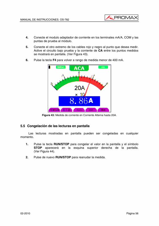
3. Conecte el modulo adaptador de corriente en los terminales mA/A, COM y las puntas de prueba al módulo.
4. Conecte el otro extremo de los cables rojo y negro al punto que desea medir. Active el circuito bajo prueba y la corriente de DC entre los puntos medidos se mostrará en pantalla. (Ver Figura 41).
5. Pulse la tecla F4 para volver a rango de medida menor de 400 mA.
Figura 41.- Medida de corriente en Corriente Continua hasta 20A.

MANUAL DE INSTRUCCIONES. OS-782
Página 55 02-2010
5.4.8 Medición de corriente en Corriente Alterna (ACA)
Para realizar la medición de corriente es necesario conectar en serie el medidor y el circuito bajo prueba. Para realizar está operación es necesario desconectar el circuito antes de realizar dicha conexión.
Para medir una corriente en CA menor de 400 mA, haga lo siguiente:
1. Pulse la tecla A y el símbolo DCA aparecerá en la parte superior de la pantalla. La unidad de medida es mA. Los símbolos mA y 20A aparecerán en la parte inferior derecha de la pantalla. Pulse F4 o F5 para cambiar el rango de medida de mA a 20A y viceversa. 400mA esta seleccionado por defecto.
2. Pulse la tecla AUTO SET y el símbolo ACA aparecerá en la zona superior de la pantalla.
3. Inserte el cable negro en la entrada COM tipo banana y el cable rojo en el la entrada mA tipo banana.
4. Conecte el otro extremo de los cables rojo y negro al punto que desea medir. Active el circuito bajo prueba y la corriente de CA entre los puntos medidos se mostrará en pantalla. (Ver Figura 42).
Figura 42.- Medida de corriente en Corriente Alterna hasta 400 mA.
Para medir una corriente en CA mayor de 400 mA, haga lo siguiente:
1. Pulse la tecla AUTO SET y el símbolo ACA aparecerá en la zona superior de
la pantalla.
2. Pulse F5 para cambiar el rango de medida a 20A. La unidad de medida cambiará a A.
3. Pulse la tecla AUTO SET y el símbolo ACA aparecerá en la zona superior de la pantalla.
MANUAL DE INSTRUCCIONES. OS-782
02-2010 Página 56
4. Conecte el modulo adaptador de corriente en los terminales mA/A, COM y las puntas de prueba al módulo.
5. Conecte el otro extremo de los cables rojo y negro al punto que desea medir. Active el circuito bajo prueba y la corriente de CA entre los puntos medidos se mostrará en pantalla. (Ver Figura 43).
6. Pulse la tecla F4 para volver a rango de medida menor de 400 mA.
Figura 43: Medida de corriente en Corriente Alterna hasta 20A.
5.5 Congelación de las lecturas en pantalla
Las lecturas mostradas en pantalla pueden ser congeladas en cualquier momento.
1. Pulse la tecla RUN/STOP para congelar el valor en la pantalla y el símbolo STOP aparecerá en la esquina superior derecha de la pantalla. (Ver Figura 44).
2. Pulse de nuevo RUN/STOP para reanudar la medida.

MANUAL DE INSTRUCCIONES. OS-782
Página 57 02-2010
Figura 44: Congelación de las lecturas en pantalla.
5.6 Toma de una medida relativa
Una medida relativa se define como el valor actual de una medida respecto al valor de una medida de referencia previamente fijada.
El siguiente ejemplo muestra como tomar una medida relativa. Primero hay que adquirir un valor de referencia. 1. Pulse la tecla R y la letra R aparecerá en la parte superior de la pantalla.
2. Pulse la tecla AUTO SET hasta que aparezca la letra C en la parte superior de la pantalla.
3. Conecte el módulo extendido de capacitancia en el conector jack de medida de capacidad.
4. Cuando la lectura se estabilice, pulse la tecla F2 y el símbolo aparece en la parte superior de la pantalla. El valor de referencia guardado aparece debajo del
símbolo .
5. Conecte la capacitancia. La lectura principal mostrada en pantalla es el valor real de la capacitancia.
En la pantalla se puede apreciar una imagen parecida a la de siguiente figura.

MANUAL DE INSTRUCCIONES. OS-782
02-2010 Página 58
Figure 45.- Medición Relativa.
5.7 Selección de rango automático/manual
El modo de selección de rango del equipo está predeterminado como automático. Para cambiar a modo manual siga los siguientes pasos:
1. Pulse la tecla F1 y el símbolo MANUAL aparecerá en la parte superior de la pantalla.
2. En modo manual, el rango de medida aumenta un nivel cada vez que se pulsa F1, y al alcanzar el nivel más alto, vuelve al nivel más bajo pulsando F1 una vez más. Multiplicando el Factor de multiplicación de la escala de medida por la lectura de la escala de medida, se obtendrá el resultado de la medida.
3. Para volver a modo automático, pulse la tecla F3 y el símbolo AUTO aparecerá en la parte superior de la pantalla. (Ver Figura 46).
Figura 46.- Selección de rango automático/manual.
ATENCIÓN Medición de la capacitancia sin modo de rango manual.

MANUAL DE INSTRUCCIONES. OS-782
Página 59 02-2010
6. POSIBLES PROBLEMAS Y SOLUCIONES
1. El osciloscopio no se enciende.
La batería puede estar agotada. En este caso, el osciloscopio no arrancará incluso si se conecta al cargador de batería. En primer lugar, cargue la batería conectando el osciloscopio al cargador. Sin embargo, no encienda el osciloscopio hasta después de 15 minutos. Si aún así el osciloscopio no puede arrancar, por favor póngase en contacto con el servicio técnico de PROMAX.
2. El osciloscopio funciona durante unos segundos y se apaga.
Probablemente la batería está agotada. Compruebe el símbolo de la batería en
la esquina superior derecha de la pantalla. El símbolo indica que la batería está agotada y debe ser cargada.
3. El mensaje ERR aparece en pantalla al encender el multímetro.
Probablemente el multímetro no está en modo de medida. En este caso, pulse cualquiera de las tres teclas V, A o R. Así, el modo de medida se mostrará en pantalla. Si el mensaje ERR no desaparece, reinicie el osciloscopio.
4. El valor de la amplitud del voltaje medido es 10 veces mayor o menor que
el real en modo de osciloscopio.
Compruebe que el factor de atenuación del canal coincida con el factor de atenuación de la sonda utilizada.
5. La forma de onda se visualiza en pantalla, pero no es estable bajo en
modo de osciloscopio.
• Compruebe que el ajuste de la señal en el menú de modo de disparo coincide con el canal en uso.
• Compruebe el modo de disparo: el modo de disparo por flanco es aplicable a una señal universal, y el modo de disparo por vídeo es aplicable a una señal de vídeo. La forma de onda solo será estable, cuando se seleccione el modo de disparo adecuado.
• Cambie el acoplamiento de disparo a HF Supresión y LF Supresión para filtrar las interferencias del ruido de disparo por HF o LF.

MANUAL DE INSTRUCCIONES. OS-782
02-2010 Página 60
6. No hay ninguna visualización en la pantalla al pulsar la tecla RUN/STOP en modo de osciloscopio. Compruebe que el modo de disparo en el menú de modo de disparo está en disparo Normal o Individual, y si el nivel de disparo está fuera del rango de la forma de onda. En este caso, seleccione la opción de modo de disparo No Automático. Pulse la tecla AUTO SET para completar los ajustes.
7. Al seleccionar el muestreo promedio en el modo de muestreo, o seleccionar un tiempo de visualización mayor en el modo de osciloscopio, la velocidad de visualización es lenta.
En este caso es lo normal.

MANUAL DE INSTRUCCIONES. OS-782
Página 61 02-2010
7. MANTENIMIENTO Y LIMPIEZA 7.1 Mantenimiento básico
No almacene o coloque el equipo en lugares donde la pantalla de cristal líquido quede directamente expuesta a la luz del sol durante mucho tiempo. Aviso: No rocíe el equipo ni las sondas con agentes líquidos o disolventes, para prevenir que se dañen. 7.2 Limpieza
Inspeccione el equipo y la sonda con frecuencia, según las condiciones de utilización. Para limpiar la superficie externa del instrumento, siga los pasos siguientes:
1. Limpie el polvo de la parte exterior del equipo y la sonda con un paño suave. Al limpiar la pantalla de cristal líquido, no raye la pantalla protectora transparente.
2. Limpie el equipo sólo cuando esté apagado, con un paño suave previamente humedecido pero no empapado. Se puede utilizar un detergente suave o agua. No use ningún detergente químico abrasivo, para evitar daños en el equipo o la sonda.
Advertencia
Antes de volver a encender y utilizar el equipo, por favor asegúrese de que se ha secado completamente, para evitar cortocircuitos y daños personales debido a la humedad.
7.3 Almacenaje de osciloscopio
Si el equipo debe permanecer almacenado durante mucho tiempo, se debe recargar la batería de litio antes del almacenaje.
7.4 Sustitución de la batería de litio.
Normalmente no es necesario cambiar la batería de litio. Si fuera necesario reemplazarla, sólo personal cualificado puede realizar esta operación. Para más información, póngase en contacto con la oficina de PROMAX más cercana o con su distribuidor.

MANUAL DE INSTRUCCIONES. OS-782
02-2010 Página 62

User’s Manual. OS-782
Eng
lish
T A B L E O F C O N T E N T S
1 GENERAL.................................................................................................................. 1 1.1 Description .......................................................................................................... 1 1.2 Specifications Oscilloscope................................................................................. 2 1.3 Specifications Multimeter .................................................................................... 5
2 SAFETY RULES........................................................................................................ 7 2.1 General................................................................................................................ 7 2.2 Descriptive Examples of Over-Voltage Categories ............................................. 9
3 DESCRIPTION FOR FRONT PANEL AND KEYS .................................................. 11 4 USING THE OSCILLOSCOPE................................................................................ 13
4.1 Power-Up the oscilloscope................................................................................ 13 4.2 Charging the oscilloscope ................................................................................. 13 4.3 Oscilloscope Operation Window ....................................................................... 14 4.4 Navigating a Menu ............................................................................................ 16 4.5 Manually Setting the Vertical System, Horizontal System and Trigger Position17 4.6 Resetting the Oscilloscope................................................................................ 20 4.7 Displaying an Unknown Signal with Auto Set ................................................... 20 4.8 Automatic zero-returning of trigger horizontal position and trigger level position..... 21 4.9 Automatic Measurements.................................................................................. 21 4.10 Freezing the Screen .......................................................................................... 22 4.11 Setting the Vertical CH1 and CH2..................................................................... 23
4.11.1 Setting the Channel Coupling ..................................................................... 24 4.11.2 Make Open and Close Settings on Channel............................................... 25 4.11.3 Adjusting the Probe Scale........................................................................... 25 4.11.4 Setting of Inverted Waveform ..................................................................... 26
4.12 MATH function “MATH” ..................................................................................... 26 4.13 Setting the Trigger System. TRIGGER Function............................................... 27 4.14 Triggering Control.............................................................................................. 28
4.14.1 Edge triggering............................................................................................ 29 Description .............................................................................................................. 29 4.14.2 Video triggering........................................................................................... 30
4.15 Acquiring Mode Setting ..................................................................................... 33 4.16 Display Setting .................................................................................................. 33
Settings ................................................................................................................... 33 4.16.1 Display Style ............................................................................................... 34 4.16.2 Persistence ................................................................................................. 34 4.16.3 XY mode ..................................................................................................... 35
4.17 Waveform Saving Setups.................................................................................. 35 4.18 Function Setting Menu ...................................................................................... 36 4.19 Making Automatic Measurements ..................................................................... 37 4.20 Setting the Cursor Measurements..................................................................... 40 4.21 Autoscale........................................................................................................... 42 4.22 System State Menu. .......................................................................................... 45 4.23 Horizontal axis setting. HORIZONTAL function ................................................ 46 4.24 Data transmission to the PC.............................................................................. 47

User’s Manual. OS-782
5 USING THE MULTIMETER..................................................................................... 49
5.1 About this chapter ............................................................................................. 49 5.2 Making Meter Connections................................................................................ 49 5.3 Multimeter Operation Window........................................................................... 49 5.4 Making Multimeter Measurements .................................................................... 51
5.4.1 Measuring Resistance Values .................................................................... 51 5.4.2 Making a Diode Measurement. ................................................................... 51 5.4.3 On-off test ................................................................................................... 52 5.4.4 Making a Capacitance Measurement ......................................................... 53 5.4.5 Making a DC voltage Measurement (VDC)................................................. 54 5.4.6 Making a AC voltage Measurement (VAC) ................................................. 54 5.4.7 Making a DC current Measurement (AAC) ................................................. 55 5.4.8 Making an AC Current Measurement ......................................................... 57
5.5 Freezing the Readings. ..................................................................................... 58 5.6 Taking a relative measurement ......................................................................... 59 5.7 Selecting automatic/manual range adjustment ................................................. 60
6 TROUBLE SHOOTING............................................................................................ 61 7 MAINTENANCE AND CLEANING........................................................................... 63
7.1 Basic maintenance ............................................................................................ 63 7.2 Cleaning ............................................................................................................ 63 7.3 Storage of oscilloscope ..................................................................................... 63 7.4 Substitution of the battery of lithium. ................................................................. 63

USER’S MANUAL. OS-782
Page 1 02-2010
Eng
lish
Oscilloscope & Multimeter Digital Storage
OS-782
1 GENERAL
1.1 Description
The OS-782 poliscope has two measurement instruments built-in: one digital oscilloscope and one multimeter. Its rugged construction, small size, lightweight and battery-powered, lead it to be a handheld instrument ideal to carry out multiple external measurements, where to work with conventional equipments it is very uncomfortable. It is very useful to measure the electrical magnitudes and to repair electronic equipments given its large diversity of functions, which causes that it become an useful tool in laboratories, as well as for R&D and training activities.
The measurement carried out by the equipment appears on a hi-resolution LCD with backlight.
Their basic characteristics in each one of their operating modes are:
• Two-channels oscilloscope with bandwidth of 20 MHz.
• Sampling rate of 100 MS/s.
• Trigger: TV and edge.
• 20 automatic measurements modes.
• Auto-scale function.
• Memory depth of 6k points by channel.
• USB port.
• Digital Multimeter of 3 ¾ for measurements of R, V, A and C.
• AC adapter and LI-ion battery.
• Display LCD colour of 3.8 " with backlight, 320x240 pixels.
• Vertical and horizontal cursors.

USER’S MANUAL. OS-782
02-2010 Page 2
1.2 Specifications Oscilloscope
Only if another instructions are provided, are all technical specifications applicable to the probe with the 10X attenuation switch setting and the HDS series digital type oscilloscope. In order to be up to these specifications, the oscilloscope should meet the following requirement.
• The instrument should operate continuously for more than 30 minutes under the specified operating temperature.
• If the operating temperature range of variation is up to or larger than 5
Celsius degrees, the system function menu must be opened to make the system perform a “self - calibration” procedure.
Except those specifications marked with the word “Typical”, all specifications can
be up to. SAMPLING
Sampling modes Normal sampling. Peak detection. Average value.
Sampling rate 100 MSa/s. INPUT
Input coupling DC, AC, Ground. Input impedance 1MΩ ± 2 % connected in parallel with 20pF
± 5 pF. Probe attenuation coefficient 1x, 10x, 100x, 1000x. Max. Input voltage 400V (peak). Channel delay time(typical) 150 ps.
HORIZONTAL
Sampling rate range 10S/s~100MS/s. Waveform interpolation (sin x)/x. Record length 6 K points on each channel. Scanning speed range (S/div) 5ns/div~100 s/div, stepping in the “1- 2.5 - 5“. Sampling rate and relay time accuracy ±100ppm(any time interval which is equal to or
larger than 1ms). Time interval (T) measurement Accuracy full bandwidth l Single: ± (1 sampling interval time+100 ppm
reading+0.6 ns)>average 16: ±(1 sampling interval time +100 ppm reading+0.4 ns).
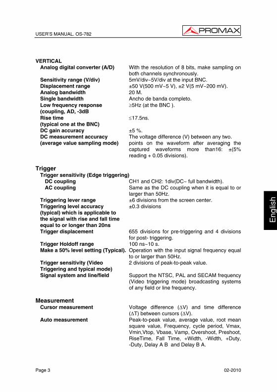
USER’S MANUAL. OS-782
Page 3 02-2010
Eng
lish
VERTICAL
Analog digital converter (A/D) With the resolution of 8 bits, make sampling on both channels synchronously.
Sensitivity range (V/div) 5mV/div~5V/div at the input BNC. Displacement range ±50 V(500 mV~5 V), ±2 V(5 mV~200 mV). Analog bandwidth 20 M. Single bandwidth Ancho de banda completo. Low frequency response ≥5Hz (at the BNC ). (coupling, AD, -3dB Rise time ≤17.5ns. (typical one at the BNC) DC gain accuracy ±5 %. DC measurement accuracy The voltage difference (V) between any two. (average value sampling mode) points on the waveform after averaging the
captured waveforms more than16: ±(5% reading + 0.05 divisions).
Trigger
Trigger sensitivity (Edge triggering) DC coupling CH1 and CH2: 1div(DC~ full bandwidth). AC coupling Same as the DC coupling when it is equal to or
larger than 50Hz. Triggering lever range ±6 divisions from the screen center. Triggering level accuracy ±0.3 divisions (typical) which is applicable to the signal with rise and fall time equal to or longer than 20ns Trigger displacement 655 divisions for pre-triggering and 4 divisions
for post- triggering. Trigger Holdoff range 100 ns~10 s. Make a 50% level setting (Typical). Operation with the input signal frequency equal
to or larger than 50Hz. Trigger sensitivity (Video 2 divisions of peak-to-peak value. Triggering and typical mode) Signal system and line/field Support the NTSC, PAL and SECAM frequency
(Video triggering mode) broadcasting systems of any field or line frequency.
Measurement
Cursor measurement Voltage difference (∆V) and time difference (∆T) between cursors (∆V).
Auto measurement Peak-to-peak value, average value, root mean square value, Frequency, cycle period, Vmax, Vmin,Vtop, Vbase, Vamp, Overshoot, Preshoot, RiseTime, Fall Time, +Width, -Width, +Duty, -Duty, Delay A B and Delay B A.
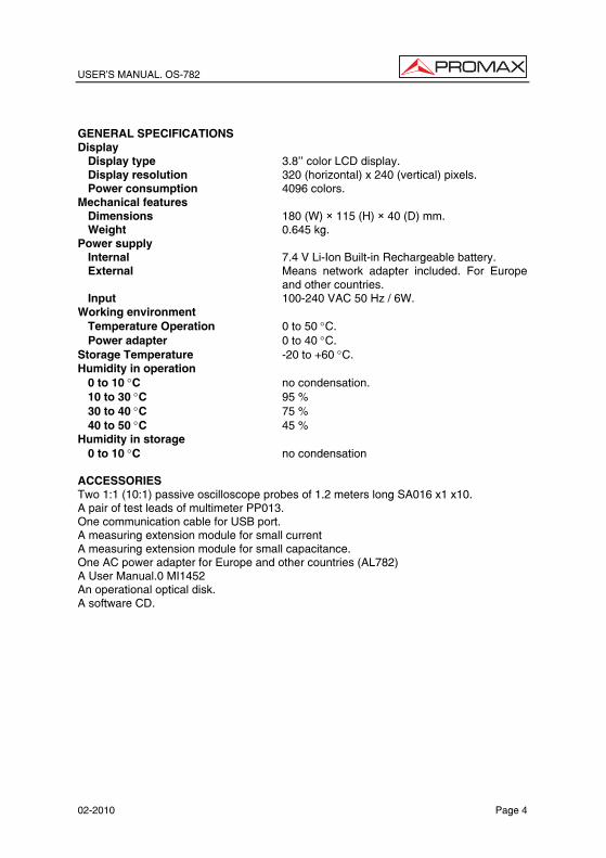
USER’S MANUAL. OS-782
02-2010 Page 4
GENERAL SPECIFICATIONS Display
Display type 3.8’’ color LCD display. Display resolution 320 (horizontal) x 240 (vertical) pixels. Power consumption 4096 colors.
Mechanical features Dimensions 180 (W) × 115 (H) × 40 (D) mm. Weight 0.645 kg.
Power supply Internal 7.4 V Li-Ion Built-in Rechargeable battery. External Means network adapter included. For Europe
and other countries. Input 100-240 VAC 50 Hz / 6W.
Working environment Temperature Operation 0 to 50 °C. Power adapter 0 to 40 °C.
Storage Temperature -20 to +60 °C. Humidity in operation
0 to 10 °C no condensation. 10 to 30 °C 95 % 30 to 40 °C 75 % 40 to 50 °C 45 %
Humidity in storage 0 to 10 °C no condensation
ACCESSORIES Two 1:1 (10:1) passive oscilloscope probes of 1.2 meters long SA016 x1 x10. A pair of test leads of multimeter PP013. One communication cable for USB port. A measuring extension module for small current A measuring extension module for small capacitance. One AC power adapter for Europe and other countries (AL782) A User Manual.0 MI1452 An operational optical disk. A software CD.

USER’S MANUAL. OS-782
Page 5 02-2010
Eng
lish
1.3 Specifications Multimeter Maximum tension of the points of measure to land 400V CAT II Voltage (VDC)
Input Impedance: 10MΩ
Range Accuracy Resolution 400 mV 100 µV 4.000 V 1 mV 40.00 V 10 mV 400.0 V
± 1% ± 1 digit
100 mV Input protection 1000 VDC or peak AC
Voltage (VAC)
Input Impedance: 10M Ω. Frequency range: from 40 Hz to 400 Hz. Display: Virtual value of the sine wave.
Range Accuracy Resolution 4.000 V 1 mV 40.00 V 10 mV 400.0 V
± 1% ± 3 digits 100 mV
Input protection 750 VDC or peak AC Direct Current (ADC)(1)
Range Accuracy Resolution 40.00 mA ± 1% ± 1 digit 10 uA 400.0 mA ± 1.5% ± 1 dígito 100uA
20A(2) ± 3% ± 3 dígitos 10 mA
Alternating Current (AAC) (1)
Range Accuracy Resolution 40.00 mA ± 1.5% ± 3 digits 10 uA 400.0 mA ± 2% ± 1 digit 100 uA
20A(2) ± 5% ± 3 digits 10 mA (1) ATENTION: Not to overcome in any case 400mA or 20A respectively. (2) With the extension module of measure of current.
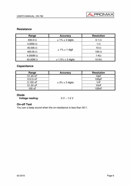
USER’S MANUAL. OS-782
02-2010 Page 6
Resistance
Range Accuracy Resolution
400.0 Ω ± 1% ± 3 digits 0.1 Ω
4.000k Ω 1 Ω
40.00k Ω 10 Ω
400.0k Ω 100 Ω
4.000M Ω
± 1% ± 1 digit
1 KΩ
40.00M Ω ± 1.5% ± 3 digits 10 KΩ Capacitance
Range Accuracy Resolution 51.20 nF 10pF 512.0 nF 100pF 5.120 uF 1nF 51.20 uF 10nF 100 uF
± 3% ± 3 digits
100nF Diode
Voltage reading: 0 V ~ 1.5 V On-off Test You can a beep sound when the on-resistance is less than 50Ω.

USER’S MANUAL. OS-782
Page 7 02-2010
Eng
lish
2 SAFETY RULES 2.1 General
* Only use this equipment as OSCILLOSCOPE in systems with their negative of measurement connected to no-dangerous voltages with respect to the ground potential.
* Only use the equipment as MULTIMETER in points with a maximum potential of 400 V with respect to the ground potential and over voltage category CAT II.
* This equipment can be used in Overvoltage Category II installations and Pollution Degree 2 environments.
The adapter of net can be used only in interiors.
* When using some of the following accessories use only the specified ones to ensure safety
Power adapter. Test leads (Multimeter) Measurement probes (Oscilloscope)
* The negative of measurement like Osciloscope is common to the negative potential of the conector of input / output of information.
* El negative of measurement of the channels of the osciloscopio is common.
* On having effected measurements to disconnect the cables that are not in use.
* Revise the condition of test leads before the utilization.
* Observe all specified ratings both of supply and measurement.
* Remember that voltages higher than 70 V DC or 33 V AC rms are dangerous.
* Use this instrument under the specified environmental conditions.
* The user not authorized to carry out the following maintenance operations. Any change on the equipment should be carrier out byqualified personnel.
* Do not obstruct the ventilation system.
* Follow the cleaning instructions described in the Maintenance paragraph.

USER’S MANUAL. OS-782
02-2010 Page 8
* Symbols related with safety: DIRECT CURRENT ALTERNATING CURRENT DIRECT AND ALTERNATING
GROUND TERMINAL
PROTECTIVE CONDUCTOR
FRAME TERMINAL
EQUIPOTENTIALITY
ON (Supply)
OFF (Supply)
DOUBLE INSULATION (Class II Protection)
CAUTION (Risk of electric shock)
CAUTION REFER TO MANUAL FUSE

USER’S MANUAL. OS-782
Page 9 02-2010
Eng
lish
2.2 Descriptive Examples of Over-Voltage Categories Cat I Low voltage installations isolated from the mains Cat II Portable domestic installations Cat III Fixed domestic installations Cat IV Industrial installations

USER’S MANUAL. OS-782
02-2010 Page 10

USER’S MANUAL. OS-782
Page 11 02-2010
Eng
lish
3 DESCRIPTION FOR FRONT PANEL AND KEYS
See the following Figure 1 :
Figure 1.- Front Pannel. Description:
1. Power adapter jack.
2. USB port.
3. Backlight switch.
4. : Power switch.
5. A: Multimeter current measurement key.

USER’S MANUAL. OS-782
02-2010 Page 12
6. V: Multimeter voltage measurement key.
7. R: Multimeter resistance, triode, On/Off and capacitance measurement key.
8. OSC : Oscilloscope left-direction adjustment key.
9. OSC : Oscilloscope right-direction adjustment key.
10. OSC OPTION: Oscilloscope setting key.
With the combination application of the four keys “OSC ”, “OSC ”, “OSC ” y “OSC ”, the users can make the following settings circularly by pressing OSC OPTION. The settings include: Voltage Unit Scale of Channel 1 (CH1 VOL); Voltage Unit Scale of Channel 2 (CH2 VOL); Primary Timebase (TIME BASE), zero point position of channel 1(CH1 ZERO), zero point position of channel 2(CH2 ZERO), trigger horizontal position (TIME) and trigger level position (TRIG).
• When performing Waveform Calculation, the users can also adjust and
calculate the Display Multiplying Factor of waveform (CHM VOL) and the vertical display position (CHM ZERO).
• In cursor measurement mode, the users can adjust the positions of Cursor 1 (V1 or T1) and Cursor 2 (V2 or T2).
11. OSC : Oscilloscope display downward adjustment key.
12. OSC : Oscilloscope display upward adjustment key.
13. OSC/DMM: Operation mode switching key between oscilloscope and multimeter.
14. AUTOSET: Oscilloscope “AUTOSET” setting key.
• Under the Multimeter Mode, when performing the current or voltage measurement, you can make a measurement switch between AC and DC with this key pressed; when performing the resistance measurement, you can select resistance, diode, On/Off or capacitance measurement circularly with this key.
• While this key is used for auto setting under the oscilloscope operation mode.
15. RUN/STOP: key for running or stopping the operation.
16. MENU : Choose the lower item on the menu list.
17. MENU: Show / Hide the menu.
18. MENU : Choose the upper item on the menu list.
19. F1~F5: Switch or Adjust options for each menu.
20. BCN input connectors for oscilloscope channels: CH1 and CH2.
21. Multimeter input terminals: Three terminals banana-type; Ma/A, COM, V/Ω/C and two socket terminals for capacitance measurement.
22. Probe compensation output. Test signal of 5 Vpp and 1 kHz frequency.
USER’S MANUAL. OS-782
Page 13 02-2010
Eng
lish
4 USING THE OSCILLOSCOPE 4.1 Power-Up the oscilloscope
Connect oscilloscope to AC power via a power adapter as shown in Figure 1. (The oscilloscope may still work with built-in Li-ion battery even without AC power supply).
Turn the oscilloscope on by pressing down the power on/off key “ “.
The instrument then performs Selfchecking after power on. A greeting window and a sentence “press any key to continue” will display on the screen when the system finishes selfchecking.
The users can press any key to enter the measuring function.
The oscilloscope is powered up in its last setup configuration. 4.2 Charging the oscilloscope
The lithium battery is possibly not charged when delivery. To make the battery with enough electric quantity, it must be charged for 4 hours (the test tool must be turned off during charging). The battery can supply power for 4 hours after being charged completely.
When supplying power by using the battery, a battery indicator is displayed on the top of the screen to show the consumption condition of electric quantity. The symbols
that are possibly appear include , , and , where shows that the battery can only be used for about 5 minutes. To charge the battery and power the instrument, connect the oscilloscope using a power adapter according to Figure 1 to charge the battery. The charging speed can be increased by turning off the test tool. NOTE To avoid superheat of battery during charging, the environment temperature is
not allowed to exceed the permissible value given in technical specification. NOTE: No hazard will occur even connecting the charger for a long time, e.g. during a
whole weekend. The instrument can automatically switch to slowly charging status.
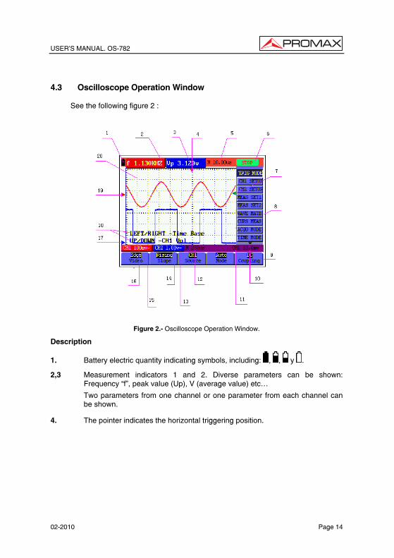
USER’S MANUAL. OS-782
02-2010 Page 14
4.3 Oscilloscope Operation Window
See the following figure 2 :
Figure 2.- Oscilloscope Operation Window.
Description
1. Battery electric quantity indicating symbols, including: , , y .
2,3 Measurement indicators 1 and 2. Diverse parameters can be shown: Frequency “f”, peak value (Up), V (average value) etc…
Two parameters from one channel or one parameter from each channel can be shown.
4. The pointer indicates the horizontal triggering position.
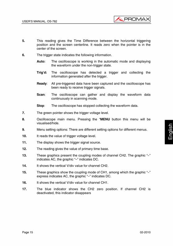
USER’S MANUAL. OS-782
Page 15 02-2010
Eng
lish
5. This reading gives the Time Difference between the horizontal triggering position and the screen centerline. It reads zero when the pointer is in the center of the screen.
6. The trigger state indicates the following information.
Auto: The oscilloscope is working in the automatic mode and displaying the waveform under the non-trigger state.
Trig’d: The oscilloscope has detected a trigger and collecting the information generated after the trigger.
Ready: All pre-triggered data have been captured and the oscilloscope has been ready to receive trigger signals.
Scan: The oscilloscope can gather and display the waveform data continuously in scanning mode.
Stop: The oscilloscope has stopped collecting the waveform data.
7. The green pointer shows the trigger voltage level.
8. Oscilloscope main menu. Pressing the “MENU button this menu will be visualised/hide.
9. Menu setting options: There are different setting options for different menus.
10. It reads the value of trigger voltage level.
11. The display shows the trigger signal source.
12. The reading gives the value of primary time base.
13. These graphics present the coupling modes of channel CH2. The graphic “∼” indicates AC, the graphic “—” indicates DC.
14. It shows the vertical V/div value for channel CH2.
15. These graphics show the coupling mode of CH1, among which the graphic “∼” express indicates AC, the graphic “—” indicates DC.
16. It shows the vertical V/div value for channel CH1.
17. The blue indicator shows the CH2 zero position. If channel CH2 is deactivated, this indicator disappears

USER’S MANUAL. OS-782
02-2010 Page 16
18. OSC OPTION indications: Whenever you press the OSC OPTION they are shown parameters to be modified by means of the cursor keys: , , and
.
19. The red indicator shows the CH1 zero position. If channel CH1 is deactivated, this indicator disappears.
20. Waveform display area. Red waveform represent CH1, blue waveform represent CH2.
4.4 Navigating a Menu
The following example shows how to use the tool’s menus to select a function, as shown in the following figure.
1. Press the MENU key to show the Functions Menu in the right side of the display and the corresponding parameters or options in the lower part of the display. In order to hide the Functions Menu press the MENU key again.
2. Press the MENU or MENU key to select different function menus.
3. Press a key from F1 to F5 to modify the diverse parameters of each function.
Figure 3.- The tool’s menus.

USER’S MANUAL. OS-782
Page 17 02-2010
Eng
lish
4.5 Manually Setting the Vertical System, Horizontal System and
Trigger Position
With the combination application of the four keys “OSC ”, “OSC ”, “OSC ” and “OSC ”, the users can make the following settings circularly by pressing OSC OPTION. The settings include: Voltage Unit Scale of Channel 1 (CH1 VOL); Voltage Unit Scale of Channel 2 (CH2 VOL); Primary Timebase (TIME BASE), zero point position of channel 1(CH1 ZERO), zero point position of channel 2(CH2 ZERO), trigger horizontal position (TIME) and trigger level position (TRIG).
The following example shows how to use “OSC OPTION” key to make a setting.
1. Press once the “OSC OPTION” key; the following is displayed at the bottom left side of the screen, as shown in the figure below.
/ — Time Base
/ — CH1 Vol
Figure 4.- Voltage Unit Scale of Channel 1.
2. Press the key “OSC ” or “OSC ” to adjust the vertical scale of Channel 1 and press , y “OSC ” “OSC ” to adjust the horizontal time scale.
3. Press “OSC OPTION” once again, the following display is visible at bottom left side of the screen, as shown in the following figure:
/ — Time Base
/ — CH2 Vol
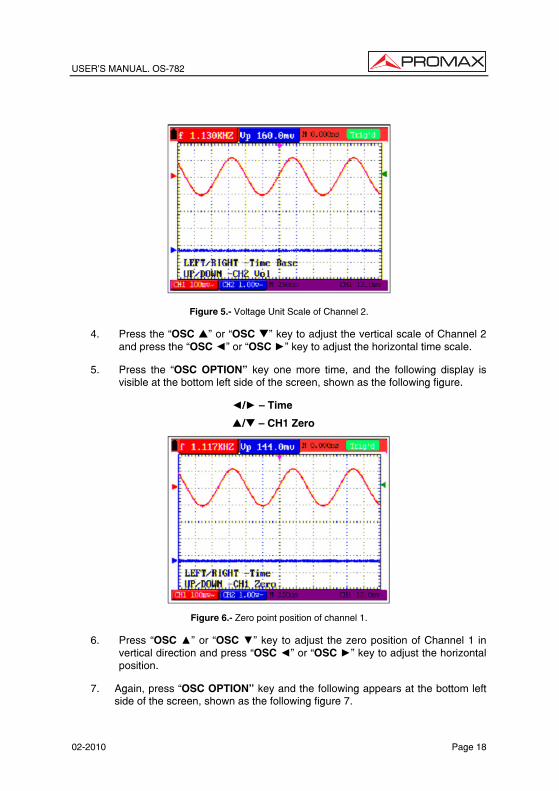
USER’S MANUAL. OS-782
02-2010 Page 18
Figure 5.- Voltage Unit Scale of Channel 2.
4. Press the “OSC ” or “OSC ” key to adjust the vertical scale of Channel 2 and press the “OSC ” or “OSC ” key to adjust the horizontal time scale.
5. Press the “OSC OPTION” key one more time, and the following display is visible at the bottom left side of the screen, shown as the following figure.
/ — Time
/ — CH1 Zero
Figure 6.- Zero point position of channel 1.
6. Press “OSC ” or “OSC ” key to adjust the zero position of Channel 1 in vertical direction and press “OSC ” or “OSC ” key to adjust the horizontal position.
7. Again, press “OSC OPTION” key and the following appears at the bottom left side of the screen, shown as the following figure 7.
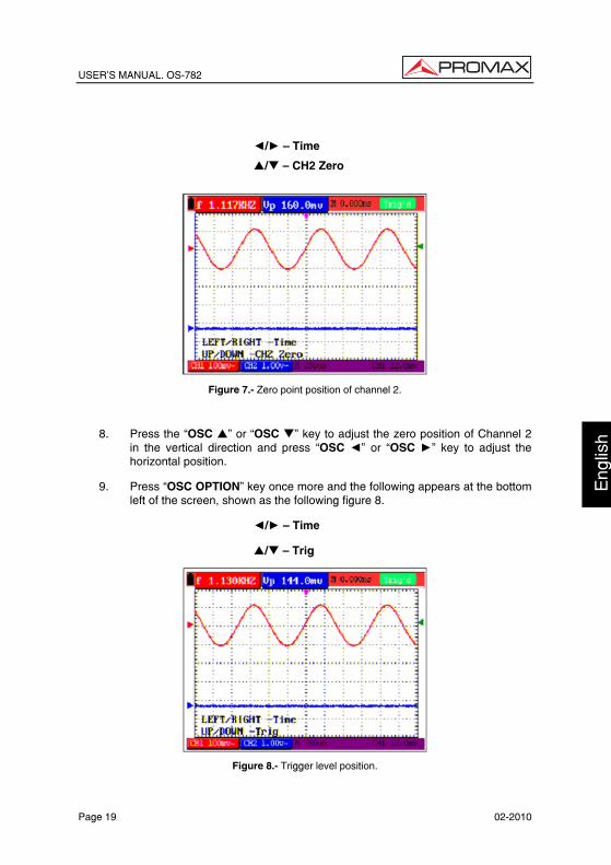
USER’S MANUAL. OS-782
Page 19 02-2010
Eng
lish
/ — Time
/ — CH2 Zero
Figure 7.- Zero point position of channel 2.
8. Press the “OSC ” or “OSC ” key to adjust the zero position of Channel 2 in the vertical direction and press “OSC ” or “OSC ” key to adjust the horizontal position.
9. Press “OSC OPTION” key once more and the following appears at the bottom left of the screen, shown as the following figure 8.
/ — Time
/ — Trig
Figure 8.- Trigger level position.

USER’S MANUAL. OS-782
02-2010 Page 20
10. Press the “OSC ” or “OSC ” key to adjust the trigger position of Channel 2
and press “OSC ” or “OSC ” key to adjust the horizontal position.
11. Press the “OSC OPTION” key again and return back to step 1.
4.6 Resetting the Oscilloscope
If you want to reset the Oscilloscope to the factory settings, do the following:
1. Press “MENU” key and the function menu appears on the right side of the screen.
2. Press the “MENU ” or “MENU ” key to select function setting and three options are visible at the bottom of the screen.
3. Press “F1” RESET key to select the factory settings. The oscilloscope is set to be the factory settings.
See the following figure 9.
Figure 9.- Reset the Oscilloscope. 4.7 Displaying an Unknown Signal with Auto Set
The Auto-Set feature lets the Oscilloscope display and measure unknown signals automatically. This function optimizes the position, range, time base, and triggering and assures a stable display of virtually any waveform. This feature is especially useful for quickly checking several signals.

USER’S MANUAL. OS-782
Page 21 02-2010
Eng
lish
To enable the Auto-Set feature, do the following:
1. Connect the test probe to the tested signals.
2. Press the AUTO SET key and the Oscilloscope is under the automatic measurement condition. The tested signals appear on the screen.
4.8 Automatic zero-returning of trigger horizontal position and trigger
level position
When we adjust the trigger horizontal position and trigger level position to be maximal to make it off the screen center remotely, then we perform the following steps to make trigger horizontal position and trigger level position return to zero automatically.
1. Press “OSC ” key and “OSC ” key simultaneously, the trigger horizontal position automatically returns to zero.
2. Press “OSC ” and “OSC ” button simultaneously, the trigger level position
automatically returns to zero. 4.9 Automatic Measurements
The Oscilloscope offers 20 ranges of automatic scope measurements. Your can display two numeric readings: measurement 1 and measurement 2. These measures are shown in the left upper part of the display and can be shown two parameters of a same channel or a parameter of each channel.
To choose a frequency for CHI1, do the following:
1. Press MENU, key and the function menu appears on the right side of the screen.
2. Press “MENU ” or “MENU ” key to select measurement 1. Five items
selectable are visible at the bottom of the screen.
3. Press F1 key and select Freq CH1 from the mean square root value item. The measurement 1 window turns its color into red and shows the frequency for input CHI.
NOTE: When pressing the F1∼F5 keys the measured channel CH1/CH2 changes
alternatively.

USER’S MANUAL. OS-782
02-2010 Page 22
To choose a Peak-Peak measurement for Input CH2, do the following:
1. Press MENU, key and the function menu is displayed on the right side of the screen.
2. Press “MENU ” or “MENU ” key and select Measurement 2, with 5 items selectable displayed at the bottom of the screen.
3. Press F4 key to select PK-PK CH2 from Peak-Peak item. The measurement 2 window turns its color to be blue and shows the peak-peak value for input CH2. (See the following figure 10).
NOTE: When pressing the F1∼F5 keys the measured channel CH1/CH2 changes alternatively.
Figure 10: Automatic scope measurements. 4.10 Freezing the Screen
You can freeze the screen (all readings and waveforms):
1. Press the RUN/STOP key to freeze the screen and STOP appears at top right side of the screen.
2. Press the RUN/STOP key once more to resume your measurement. (See the
following figure 11).

USER’S MANUAL. OS-782
Page 23 02-2010
Eng
lish
Figure 11.- Freezing the screen.
4.11 Setting the Vertical CH1 and CH2
Each channel has its own independent vertical menu and each item can be set respectively based on the specific channel.
Open the vertical menu of functions and select to CHANNEL 1 or CHANNEL 2 functions. The parameters to be modified with F1∼F5 keys appear in the lower part of the display.
Figure 12.- Setting the Vertical CH1 and CH2.
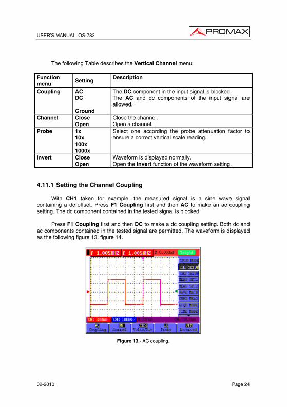
USER’S MANUAL. OS-782
02-2010 Page 24
The following Table describes the Vertical Channel menu:
Function menu
Setting Description
Coupling AC DC Ground
The DC component in the input signal is blocked. The AC and dc components of the input signal are allowed.
Channel Close Open
Close the channel. Open a channel.
Probe 1x 10x 100x 1000x
Select one according the probe attenuation factor to ensure a correct vertical scale reading.
Invert Close Open
Waveform is displayed normally. Open the Invert function of the waveform setting.
4.11.1 Setting the Channel Coupling
With CH1 taken for example, the measured signal is a sine wave signal containing a dc offset. Press F1 Coupling first and then AC to make an ac coupling setting. The dc component contained in the tested signal is blocked.
Press F1 Coupling first and then DC to make a dc coupling setting. Both dc and ac components contained in the tested signal are permitted. The waveform is displayed as the following figure 13, figure 14.
Figure 13.- AC coupling.

USER’S MANUAL. OS-782
Page 25 02-2010
Eng
lish
Figure 14.- DC coupling. 4.11.2 Make Open and Close Settings on Channel
With CH1 taken for example:
Press F2 Channel first, then Close to make a Close setting on CH1.
Press F2 Channel key first, then Open to make an Open setting on CH1. 4.11.3 Adjusting the Probe Scale
It is necessary to adjust the probe attenuation scale factor correspondingly in the channel operation menu in order to comply with the probe attenuation scale. If it is a 10:1 probe, the scale of the input channel of the oscilloscope should be selected as 10X to avoid any error occurring in the displayed scale factor information and tested data.
Press F3 Probe to jump to the relative probe:
Probe attenuation factor Corresponding Menu Setting 1:1 1x 10:1 10x 100:1 100x 1000:1 1000x
Table.- Probe attenuation factor and the corresponding menu setting
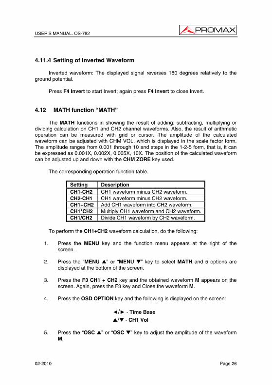
USER’S MANUAL. OS-782
02-2010 Page 26
4.11.4 Setting of Inverted Waveform
Inverted waveform: The displayed signal reverses 180 degrees relatively to the ground potential.
Press F4 Invert to start Invert; again press F4 Invert to close Invert. 4.12 MATH function “MATH”
The MATH functions in showing the result of adding, subtracting, multiplying or dividing calculation on CH1 and CH2 channel waveforms. Also, the result of arithmetic operation can be measured with grid or cursor. The amplitude of the calculated waveform can be adjusted with CHM VOL, which is displayed in the scale factor form. The amplitude ranges from 0.001 through 10 and steps in the 1-2-5 form, that is, it can be expressed as 0.001X, 0.002X, 0.005X, 10X. The position of the calculated waveform can be adjusted up and down with the CHM ZORE key used.
The corresponding operation function table.
Setting Description CH1-CH2 CH1 waveform minus CH2 waveform. CH2-CH1 CH1 waveform minus CH2 waveform. CH1+CH2 Add CH1 waveform into CH2 waveform. CH1*CH2 Multiply CH1 waveform and CH2 waveform. CH1/CH2 Divide CH1 waveform by CH2 waveform.
To perform the CH1+CH2 waveform calculation, do the following:
1. Press the MENU key and the function menu appears at the right of the
screen.
2. Press the “MENU ” or “MENU ” key to select MATH and 5 options are displayed at the bottom of the screen.
3. Press the F3 CH1 + CH2 key and the obtained waveform M appears on the
screen. Again, press the F3 key and Close the waveform M.
4. Press the OSD OPTION key and the following is displayed on the screen:
/ - Time Base
/ - CH1 Vol
5. Press the “OSC ” or “OSC ” key to adjust the amplitude of the waveform M.
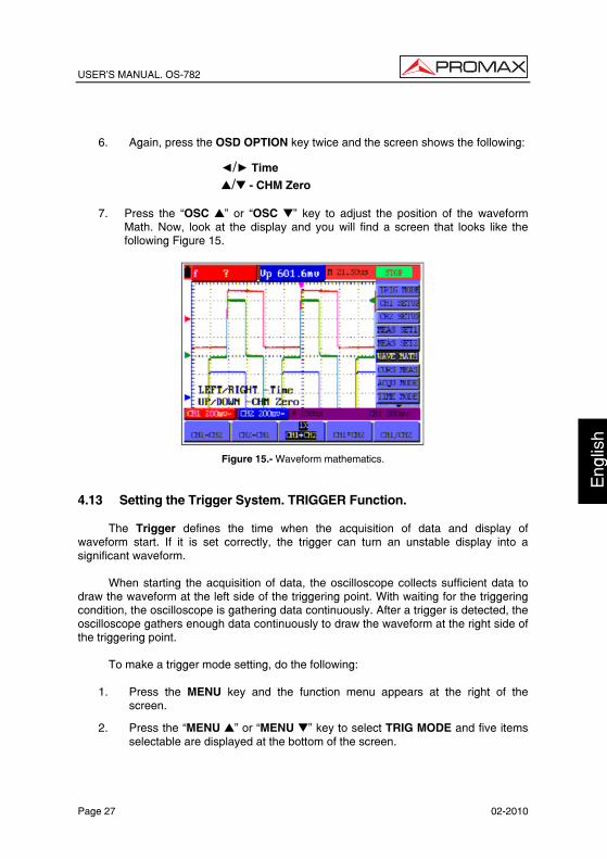
USER’S MANUAL. OS-782
Page 27 02-2010
Eng
lish
6. Again, press the OSD OPTION key twice and the screen shows the following:
/ Time
/ - CHM Zero
7. Press the “OSC ” or “OSC ” key to adjust the position of the waveform Math. Now, look at the display and you will find a screen that looks like the following Figure 15.
Figure 15.- Waveform mathematics.
4.13 Setting the Trigger System. TRIGGER Function.
The Trigger defines the time when the acquisition of data and display of waveform start. If it is set correctly, the trigger can turn an unstable display into a significant waveform.
When starting the acquisition of data, the oscilloscope collects sufficient data to draw the waveform at the left side of the triggering point. With waiting for the triggering condition, the oscilloscope is gathering data continuously. After a trigger is detected, the oscilloscope gathers enough data continuously to draw the waveform at the right side of the triggering point.
To make a trigger mode setting, do the following:
1. Press the MENU key and the function menu appears at the right of the screen.
2. Press the “MENU ” or “MENU ” key to select TRIG MODE and five items selectable are displayed at the bottom of the screen.

USER’S MANUAL. OS-782
02-2010 Page 28
3. Select and press one from F1 through F5 key to make a different setting.
4. Press the OSD OPTION key and the following is shown on the screen:
/ — Time
/ — Trig
5. Press the “OSC ” or “OSC ” key to adjust the trigger level position. Now, look at the display: you can see a screen in the following figure 16.
Figure 16.- Edge triggering.
4.14 Triggering Control
There are two triggering modes including Edge triggering and Video triggering. Each trigger mode is set by different function menu.
Edge triggering: It occurs when the trigger input passes through a given level along the specified direction.
Video triggering: Perform video field trigger or line trigger on the standard video signals.
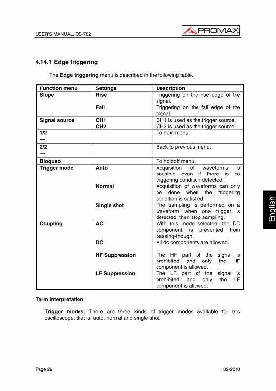
USER’S MANUAL. OS-782
Page 29 02-2010
Eng
lish
4.14.1 Edge triggering
The Edge triggering menu is described in the following table.
Function menu Settings Description Slope Rise
Fall
Triggering on the rise edge of the signal. Triggering on the fall edge of the signal.
Signal source CH1 CH2
CH1 is used as the trigger source. CH2 is used as the trigger source.
1/2
To next menu.
2/2
Back to previous menu.
Bloqueo To holdoff menu. Trigger mode Auto
Normal Single shot
Acquisition of waveforms is possible even if there is no triggering condition detected. Acquisition of waveforms can only be done when the triggering condition is satisfied. The sampling is performed on a waveform when one trigger is detected, then stop sampling.
Coupling AC DC HF Suppression LF Suppression
With this mode selected, the DC component is prevented from passing-though. All dc components are allowed. The HF part of the signal is prohibited and only the HF component is allowed. The LF part of the signal is prohibited and only the LF component is allowed.
Term interpretation
Trigger modes: There are three kinds of trigger modes available for this oscilloscope, that is, auto, normal and single shot.
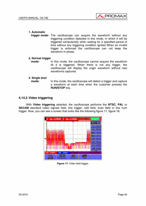
USER’S MANUAL. OS-782
02-2010 Page 30
1. Automatic
trigger mode: The oscilloscope can acquire the waveform without any triggering condition detected in this mode, in which it will be triggered compulsively when waiting for a specified period of time without any triggering condition ignited When an invalid trigger is enforced the oscilloscope can not keep the waveform in phase.
2. Normal trigger
mode: In this mode, the oscilloscope cannot acquire the waveform till it is triggered. When there is not any trigger, the oscilloscope will display the origin waveform without new waveforms captured.
3. Single shot
mode: In this mode, the oscilloscope will detect a trigger and capture a waveform at each time when the customer presses the RUN/STOP key.
4.14.2 Video triggering
With Video triggering selected, the oscilloscope performs the NTSC, PAL or SECAM standard video signals field, line trigger, odd field, even field or line num trigger. Now, you can see a screen that looks like the following figure 17, figure 18.
Figure 17: Video field trigger.
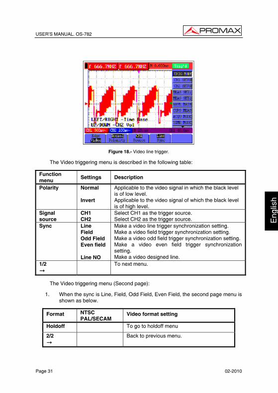
USER’S MANUAL. OS-782
Page 31 02-2010
Eng
lish
Figure 18.- Video line trigger.
The Video triggering menu is described in the following table:
Function menu
Settings Description
Polarity Normal Invert
Applicable to the video signal in which the black level is of low level. Applicable to the video signal of which the black level is of high level.
Signal source
CH1 CH2
Select CH1 as the trigger source. Select CH2 as the trigger source.
Sync Line Field Odd Field Even field Line NO
Make a video line trigger synchronization setting. Make a video field trigger synchronization setting. Make a video odd field trigger synchronization setting. Make a video even field trigger synchronization setting. Make a video designed line.
1/2
To next menu.
The Video triggering menu (Second page):
1. When the sync is Line, Field, Odd Field, Even Field, the second page menu is shown as below.
Format NTSC PAL/SECAM
Video format setting
Holdoff To go to holdoff menu
2/2
Back to previous menu.

USER’S MANUAL. OS-782
02-2010 Page 32
2. When the sync is Designed Line,the second page menu is shown as below.
Format NTSC PAL/SECAM
Video format setting
Line Increase Decrease
Set the line value to increase Set the line value to decrease
Line No. Set and Show the line valve
Holdoff To go to holdoff menu
2/2
Back to previous menu.
When you go to the holdoff menu,you can see a screen in the following figure 19.
Figure19.-Trigger Holdoff.
The Holdoff menu is described in the following table:
Function menu Settings Description Off Time Set time slot before another trigger event.
Time Increase Decrease
Set the off time to increase Set the off time to decrease.
Reset Off Time
Reset Holdoff time to 100ns.
Back Back to previous menu.

USER’S MANUAL. OS-782
Page 33 02-2010
Eng
lish
NOTE: Trigger Holdoff can stabilize complex waveform, such as the pulse
range. Holdoff time is the oscilloscope’s waiting period before starting a new trigger. During Holdoff, oscilloscope will not trigger until Holdoff ends.
4.15 Acquiring Mode Setting
Open the vertical menu of functions and select the ACQUIRE function. The parameters to be modified with F1∼F5 keys will appear in the lower part of the display.
The Acquiring Mode menu is described in the list shown as below: Function menu
Settings Description
Sampling Normal sampling mode. Peak detection
Used to detect the jamming glitch and reduce the possible blurring.
Average value
Used to reduce the random and unrelated noises. Several average factors are available for being selected.
Average factor
4, 16, 64 o 128
Select the average factor.
4.16 Display Setting
Open the vertical menu of functions and select the DISPLAY function. The parameters to be modified with F1∼F5 keys will appear in the lower part of the display.
The Display Setting menu is described in the following table:
Function menu Settings Description Type Vector
Dot
The vector is filled up spaces between neighboring sampling points in the display. Only sampling points are displayed.
Persistence Close 1s 2s 5s Infinite
Setting persistence time for each sampling point.
Display format YT XY
Display the relative relationship between vertical voltage and horizontal time. Display CH1 on the horizontal axis and CH2 on the vertical axis.
Communication Bitmap Vector
The data transmitted in communication are bitmaps. The data transmitted in communication are vectors.
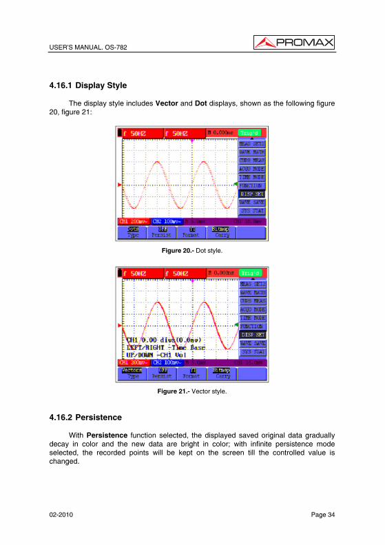
USER’S MANUAL. OS-782
02-2010 Page 34
4.16.1 Display Style
The display style includes Vector and Dot displays, shown as the following figure 20, figure 21:
Figure 20.- Dot style.
Figure 21.- Vector style.
4.16.2 Persistence
With Persistence function selected, the displayed saved original data gradually decay in color and the new data are bright in color; with infinite persistence mode selected, the recorded points will be kept on the screen till the controlled value is changed.
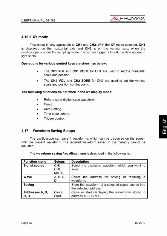
USER’S MANUAL. OS-782
Page 35 02-2010
Eng
lish
4.16.3 XY mode
This mode is only applicable to CH1 and CH2. With the XY mode selected, CH1 is displayed on the horizontal axis and CH2 is on the vertical axis; when the oscilloscope is under the sampling mode in which no trigger is found, the data appear in light spots. Operations for various control keys are shown as below:
• The CH1 VOL and CH1 ZORE for CH1 are used to set the horizontal scale and position.
• The CH2 VOL and CH2 ZORE for CH2 are used to set the vertical scale and position continuously.
The following functions do not work in the XY display mode:
• Reference or digital value waveform.
• Cursor.
• Auto Setting.
• Time base control.
• Trigger control. 4.17 Waveform Saving Setups
The oscilloscope can save 4 waveforms, which can be displayed on the screen with the present waveform. The recalled waveform saved in the memory cannot be adjusted.
The waveform saving /recalling menu is described in the following list:
Function menu Setups Description Signal source CH1
CH2 MATH
Select the displayed waveform which you want to save.
Wave A, B, C, D
Select the address for saving or recalling a waveform.
Saving Store the waveform of a selected signal source into the selected address.
Addresses A, B, C, D
Close Start
Close or start displaying the waveforms stored in address A, B, C or D.

USER’S MANUAL. OS-782
02-2010 Page 36
To save a waveform on CH1 in address A, do the following:
1. Press the MENU key and the function menu appears at the right of the
screen.
2. Press the “MENU ” or “MENU ” key to select the Waveform Saving. Four items selectable are displayed at the bottom of the screen.
3. Press the F1 key to select the signal source CH1.
4. Press the F2 key to select the address A.
5. Press the F3 key to save the waveform on CH1 in address A.
To display the saved waveform on the screen, do the following:
6. Press the F4 key to select Start for the address A. The waveform saved in
address A will be displayed on the screen in green color.
The display color is green, and the zero point of waveform k, voltage and time is purple.
Now, you can see a screen that looks like the following figure 22.
Figure 22.- Waveform Saving. 4.18 Function Setting Menu
Open the vertical menu of functions and select the SYSTEM function. The parameters to be modified with F1∼F5 keys will appear in the lower part of the display.
The function setting menu is described in the following list:

USER’S MANUAL. OS-782
Page 37 02-2010
Eng
lish
Function menu Setting Description Recall Factory Resume the instrument to its factory settings. Auto Calibration Perform the self-correcting procedure. Language SPANISH
ENGLISH Select the display language of the system.
Self-correcting
The self-correcting program can improve the accuracy of the oscilloscope under the ambient temperature to the maximum. If the ambient temperature variation is equal to or larger than 5 Celsius degrees, the self-correcting program should be performed to gain the maximum accuracy.
Before the self-correcting program is performed, the probe or lead should be disconnected with the input connector, then, select the F2 key “Self-correcting“ item. After confirming that everything is ready, press the F2 key “Self-correcting” key and enter into the self-correcting program. 4.19 Making Automatic Measurements
The oscilloscope can perform 20 types automatic measurements such as frequency, cycle, average value, peak-to-peak value , root mean square value, Vmax, Vmin, Vtop, Vbase, Vamp, Overshoot, Preshoot, RiseTime, Fall Time, +Width, -Width,
+Duty, -Duty, Delay A B and Delay A B . And gives two kinds of measurement results simultaneously on the screen.
The function menu for automatic measurements is described in the following list.
Function menu Settings Description
Freq CH1 CH2
Measure the frequency of CH1 Measure the frequency of CH2
Period CH1 CH2
Measure the Period of CH1. Measure the Period of CH2
Mean CH1 CH2
Measure the average value of CHI. Measure the average value of CH2.
Peak-Peak CH1 CH2
Measure the peak-to-peak value of CH1. Measure the peak-to-peak value of CH2.
Cyc RMS CH1 CH2
Measure root mean square (RMS) value of CH1. Measure root mean square (RMS) value of CH2.
Vmax CH1 CH2
Measure the Vmax of CH1 Measure the Vmax of CH2
Vmin CH1 CH2
Measure the Vmin of CH1 Measure the Vmin of CH2
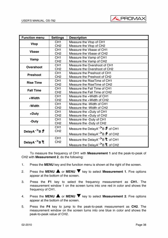
USER’S MANUAL. OS-782
02-2010 Page 38
Function menu Settings Description
Vtop CH1 CH2
Measure the Vtop of CH1 Measure the Vtop of CH2
Vbase CH1 CH2
Measure the Vbase of CH1 Measure the Vbase of CH2
Vamp CH1 CH2
Measure the Vamp of CH1 Measure the Vamp of CH2
Overshoot CH1 CH2
Measure the Overshoot of CH1 Measure the Overshoot of CH2
Preshoot CH1 CH2
Measure the Preshoot of CH1 Measure the Preshoot of CH2
Rise Time CH1 CH2
Measure the RiseTime of CH1 Measure the RiseTime of CH2
Fall Time CH1 CH2
Measure the Fall Time of CH1 Measure the Fall Time of CH2
+Width CH1 CH2
Measure the +Width of CH1 Measure the +Width of CH2
-Width CH1 CH2
Measure the -Width of CH1 Measure the -Width of CH2
+Duty CH1 CH2
Measure the +Duty of CH1 Measure the +Duty of CH2
-Duty CH1 CH2
Measure the -Duty of CH1 Measure the -Duty of CH2
DelayA B CH1 CH2
Measure the DelayA B of CH1
Measure the DelayA B of CH2
DelayA B CH1 CH2
Measure the DelayA B of CH1
Measure the DelayA B of CH2
To measure the frequency of CH1 with Measurement 1 and the peak-to-peak of CH2 with Measurement 2, do the following: 1. Press the MENU key and the function menu is shown at the right of the screen.
2. Press the MENU or MENU key to select Measurement 1. Five options appear at the bottom of the screen.
3. Press the F1 key to select the frequency measurement as CH1. The measurement window 1 on the screen turns into one red in color and shows the frequency of CH1.
4. Press the MENU or MENU key to select Measurement 2. Five options appear at the bottom of the screen.
5. Press the F4 key to jump to the peak-to-peak measurement as CH2. The measurement window on the screen turns into one blue in color and shows the peak-to-peak value of CH2.

USER’S MANUAL. OS-782
Page 39 02-2010
Eng
lish
Now, you can see a screen that looks like the following figure.
Figure 23.- Automatic Measurements.
Term interpretation
Vpp: Peak-to-Peak Voltage.
Vmax: The maximum amplitude. The most positive peak voltage measured over the entire waveform.
Vmin: The minimum amplitude. The most negative peak voltage measured over the entire waveform.
Vamp: Voltage between Vtop and Vbase of a waveform.
Vtop: Voltage of the waveform’s flat top, useful for square/pulse waveforms.
Vbase: Voltage of the waveform’s flat base, useful for square/pulse waveforms.
Overshoot: Defined as (Vmax-Vtop)/Vamp, useful for square and pulse waveforms.
Preshoot: Defined as (Vmin-Vbase)/Vamp, useful for square and pulse waveforms.
Average: The arithmetic mean over the entire waveform.
Vrms: The true Root Mean Square voltage over the entire waveform.
Rise Time: Time that the leading edge of the first pulse in the waveform takes to rise from 10% to 90% of its amplitude.
Fall Time: Time that the falling edge of the first pulse in the waveform takes to fall from 90% to 10% of its amplitude.

USER’S MANUAL. OS-782
02-2010 Page 40
+Width: The width of the first positive pulse in 50% amplitude points.
-Width: The width of the first negative pulse in the 50% amplitude points.
Delay 1→2 : The delay between the two channels at the rising edge.
Delay 1→2 : The delay between the two channels at the falling edge.
+Duty: +Duty Cycle, defined as +Width/Period.
-Duty: -Duty Cycle, defined as -Width/Period.
4.20 Setting the Cursor Measurements
This oscilloscope allows you to make manual cursor measurements on time and voltage. The signal sources include Channel 1(CH1) and Channel 2 (CH2).
The cursor measurement menus are listed and described in the following table: Function menus
Settings Description
Type Close Voltage Time
Close the cursor measurement. Display the voltage measurement cursor and menu. Display the time measurement cursor and menu.
Signal sources
CH1, CH2
Select the waveform channel on which the cursor measurement will be performed.
To make a voltage measurement on CH1, doing the following:
1. Press the MENU key and the function menus are displayed at the right of the
screen.
2. Press the “MENU ” or “MENU ” key to select Cursor Measurement. Two options are shown at the bottom of the screen.
3. Press F1 key to select the measurement type Voltage. Two purple crossing dashed lines V1 and V2 are shown on the screen.
4. Press the F2 key to select the measured channel CH1.
5. Press and hold the OSC OPTION key till the / CURSOR V1 is visible on the screen. At this time, adjust OSC or OSC and you can see that the dashed line V1 is moving up and down while the measured voltage value of V1 relative to the zero position of CH1 appears on the screen.
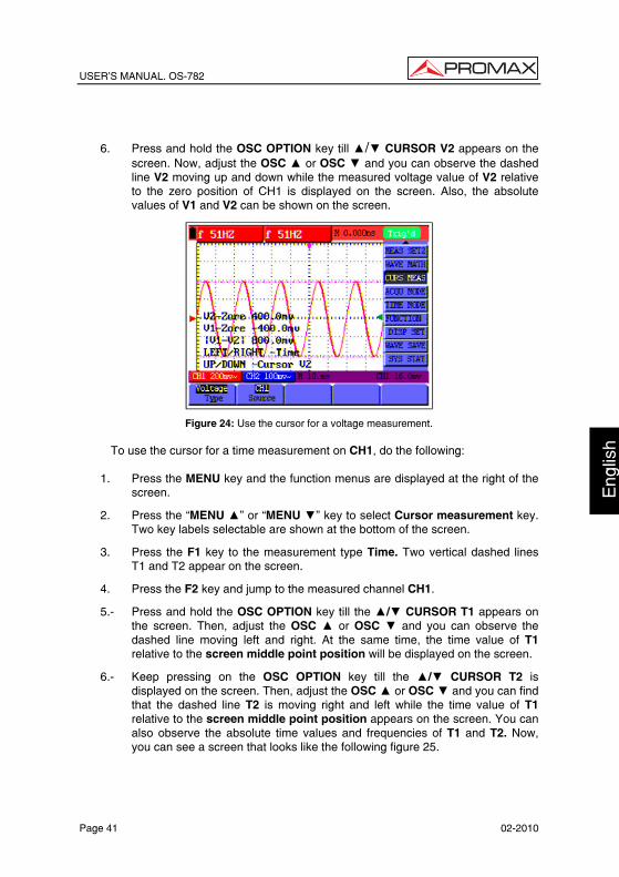
USER’S MANUAL. OS-782
Page 41 02-2010
Eng
lish
6. Press and hold the OSC OPTION key till / CURSOR V2 appears on the screen. Now, adjust the OSC or OSC and you can observe the dashed line V2 moving up and down while the measured voltage value of V2 relative to the zero position of CH1 is displayed on the screen. Also, the absolute values of V1 and V2 can be shown on the screen.
Figure 24: Use the cursor for a voltage measurement.
To use the cursor for a time measurement on CH1, do the following:
1. Press the MENU key and the function menus are displayed at the right of the
screen.
2. Press the “MENU ” or “MENU ” key to select Cursor measurement key. Two key labels selectable are shown at the bottom of the screen.
3. Press the F1 key to the measurement type Time. Two vertical dashed lines T1 and T2 appear on the screen.
4. Press the F2 key and jump to the measured channel CH1.
5.- Press and hold the OSC OPTION key till the / CURSOR T1 appears on the screen. Then, adjust the OSC or OSC and you can observe the dashed line moving left and right. At the same time, the time value of T1 relative to the screen middle point position will be displayed on the screen.
6.- Keep pressing on the OSC OPTION key till the / CURSOR T2 is displayed on the screen. Then, adjust the OSC or OSC and you can find that the dashed line T2 is moving right and left while the time value of T1 relative to the screen middle point position appears on the screen. You can also observe the absolute time values and frequencies of T1 and T2. Now, you can see a screen that looks like the following figure 25.

USER’S MANUAL. OS-782
02-2010 Page 42
Figure 25: Use the cursor for a time measurement.
4.21 Autoscale
The function is applied to follow-up signals automatically even if the signals change at any time. Autoscale enables the instrument to set up trigger mode, voltage division and time scale automatically according to the type, amplitude and frequency of the signals.
The menu is as follows: Function menus Settings Description Autoscale OFF
ON Turn off Autoscale. Turn on Autoscale.
Mode Vertical Horizontal HORI-VERT
Follow-up and adjust vertical scale without changing horizontal setting. Follow-up and adjust horizontal scale without changing vertical setting. Follow-up and adjust the vertical and horizontal settings.
Only show one or two periods. Show Multi-period waveforms.

USER’S MANUAL. OS-782
Page 43 02-2010
Eng
lish
If you want to measure voltage of Channel 1, you can do as the follows:
1. Press MENU, the function menu will appear on the right of the screen.
2. Press MENU or MENU and choose Autoscale, three options will show
at the bottom of the screen.
3. Press F1 and choose ON.
4. Press F2 and choose Hori- Vert.
5. Press F3 and displays on the screen as figure 52:
Figure 26.-: Autoscale Horizontal- Vertical multi-period waveforms.
Figure 27.- Autoscale Horizontal- Vertical mono-period waveform.

USER’S MANUAL. OS-782
02-2010 Page 44
Figure 28.- Only under vertical mode multi-period waveform.
Figure 29.- Only under horizontal mode multi-period waveform. NOTE:
1. Entering into Autoscale function and flicker will be on the top left corner. (flicker every 0.5 second).
2. At the mode of Autoscale, the oscilloscope can self-estimate “Trigger mode”
(Edge, Video, and Alternate) and “Type” (Edge, Video). If now, you press “Trigger mode” or “Type”, the forbidden information will display on the screen.
3. At the mode of XY and STOP status, pressing AUTO SET to enter into
Autoscale, DSO switches to YT mode and AUTO status.

USER’S MANUAL. OS-782
Page 45 02-2010
Eng
lish
4. At the mode of Autoscale, DSO is always in the state of DC coupling and
AUTO triggering. In this case, the forbidden information will be showing when making Triggering or Coupling settings.
5. At the mode of Autoscale, if adjust the vertical position, voltage division,
trigger level or time scale of CH1 or CH2, the oscilloscope will turn off Autoscale function and if press AUTOSET again, the oscilloscope will enter into Autoscale.
6. Turn off the submenu at the Autoscale menu, the Autoscale is off and turn on
the submenu still enters into the function.
7. When video triggering, the horizontal time scale is 50us. If one channel is showing edge signal, the other channel is showing video one, the time scale refers to 50us as video one as standard.
4.22 System State Menu.
The system state menu is used to display information about the present horizontal system, vertical system, trigger system and others. The operation steps are shown as below.
1. Press the MENU key and the function menu is displayed at the right of the screen.
2. Press the “MENU ” or “MENU ” key to select the System State. Four options appear at the bottom of the screen.
3. Sequentially press key F1 through F4 key and the corresponding state information will be shown on the screen. The screen that looks like the following figure 30 will be displayed.
Figure 30.- System State.

USER’S MANUAL. OS-782
02-2010 Page 46
4.23 Horizontal axis setting. HORIZONTAL function
Open the vertical menu of functions and select the HORIZONTAL function. The parameters to be modified with F1∼F5 keys will appear in the lower part of the display.
The time base mode menu is explained as the following table:
Function menu Setting Explanation
Main time base Horizontal main time base is used to wave display Zone Window Use two cursors to define a window area Window extensión Expand the defined window to full-screen display
For the operation of window extension, please execute the following steps:
1. Press MENU key, display the function menu on the right side of the screen.
2. Press “MENU ” or “MENU ” key to select time base mode, display three options at the bottom.
3. Press F2 key to select window setting.
4. Press OSC OPTION key, pop up TIME BASE, at this time, then press OSC /OSC key to adjust the time base window area defined by two cursors, the window size will vary.
5. Press OSC OPTION, key and call OSC / OSC to adjust the window position defined by two cursors, the window position is the time difference of the window center to main time base’s horizontal pointer.
6. Press F3 key, select window extension, the defined window extends into the full-screen display.
The screen that looks like the following figure 27, 28 will be displayed.
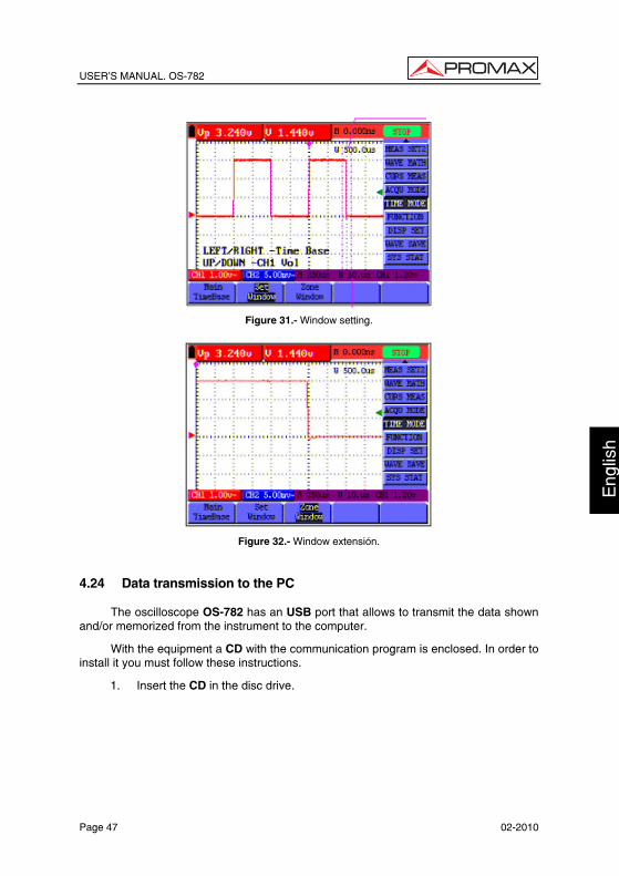
USER’S MANUAL. OS-782
Page 47 02-2010
Eng
lish
Figure 31.- Window setting.
Figure 32.- Window extensión.
4.24 Data transmission to the PC
The oscilloscope OS-782 has an USB port that allows to transmit the data shown and/or memorized from the instrument to the computer.
With the equipment a CD with the communication program is enclosed. In order to install it you must follow these instructions.
1. Insert the CD in the disc drive.

USER’S MANUAL. OS-782
02-2010 Page 48
2. Open the explorer and run the Setup.exe file and follow the installer instructions. By default the program is installed in folder: c \ Program files \ PROMAX\OS-wave.
3. Once installed, connect the USB cable between the equipment and the PC. Power on the instrument, the PC will automatically detect a new equipment and request about installing the suitable driver.
4. Select the advanced method of installation and in the following screen select the folder: USBDRIVE which there is within the directory where the program has been installed. Press “Next” to install the driver.
5. Now you can open the HDSO Wave program to capture data using the PC.

USER’S MANUAL. OS-782
Page 49 02-2010
Eng
lish
5 USING THE MULTIMETER 5.1 About this chapter
This chapter provides a step-by-step introduction to the multi-meter functions of the test tool(hereafter. The introduction gives basic examples to show how to use the menus and perform basic operations.
5.2 Making Meter Connections
Use the three 4-mm safety banana jack inputs for the Meter functions: COM, V/Ω mA. Two quadratic capacitance jacks: CX. See figure 1 for the connections.
5.3 Multimeter Operation Window
Figure 33.-

USER’S MANUAL. OS-782
02-2010 Page 50
Description
1.- Battery electric quantity indictor.
2.- MANUAL/AUTO RANGE indictors, among which the MANUAL means measuring range in manual operation mode and Auto refers to the measuring range in automatic operation mode.
3.- Measurement mode indicators:
DCV: Direct voltage measurement CC.
ACV: Alternating voltage measurement CA.
DCA: Direct current measurement CC.
ACA: Alternating current measurement CA.
R: Resistance measurement.
: Diode measurement.
: On/Off measurement.
C: Capacitance measurement.
4.- The relative magnitude measurement indicator.
5.- Running state indicators, among which RUN expresses continuous update and STOP represents the screen locking.
6.- The reference value of the relative magnitude measurement.
7.- The multiplying power of the dial indication. To multiply the reading of dial pointer by multiplying power will get the measurement result.
8.- The mail reading of measurement.
9.- Automatic control measuring range.
10.- Absolute/ relative magnitude measuring control: The sign “||” expresses the absolute magnitude measuring control and “∆” represents the relative magnitude measuring control.
11.- Manual control of the measurement range.
12.- Measurement analogue range. Test lead indicates the scale of test reading, different test modes display different colors.

USER’S MANUAL. OS-782
Page 51 02-2010
Eng
lish
5.4 Making Multimeter Measurements
Press DMM/OSC key, the oscilloscope will switch to the multimeter measure, the screen will display the multimeter windows, at the same time, prompt to correctly insert testing pen of the multimeter, at this time, then press any key to enter into multimeter measure. 5.4.1 Measuring Resistance Values
To measure a resistance, do the following:
1. Press the R key and R appears at the top of the screen.
2. Insert the black lead into the COM banana jack input and the red lead into the V/Ω banana jack input.
3. Connect the red and black test leads to the resistor. The resistor value readings are shown on the screen in Ohm. Now, you can see a screen that looks like the following figure 34.
Figure 34.- Measure resístance.
5.4.2 Making a Diode Measurement.
To make a measurement on the diode, do the following:
1. Press the R key and R appears at the top of the screen.
2. Press AUTO SET key once and the following is displayed on the screen
.

USER’S MANUAL. OS-782
02-2010 Page 52
3. Insert the black lead into the COM banana jack input and the red lead into the V/Ω banana jack input.
4. Connect the red and black leads to the resistor and the diode resistor readings are displayed on the screen in V. Now, you can see a screen that looks like the following Figure 35.
Figure 35: Diode Measurement
5.4.3 On-off test
To perform an On-off test, do the following:
1. Press the R key and R appears on the top of the screen.
2. Press the AUTO SET key three times and the following is shown on the
screen .
3. Insert the black lead into the COM banana jack input and the red lead into the V/Ω banana jack input.
4. Connect the red and black leads to the test point. If the resistance value of the tested point is less than 50 Ω, you will hear beep sound from the test tool. Now, you can see a screen that looks like the following Figure 36.

USER’S MANUAL. OS-782
Page 53 02-2010
Eng
lish
Figure 36.- On-off test.
5.4.4 Making a Capacitance Measurement
To measure a capacitance, do the following:
1. Press the R key and R appears on the top of the screen
2. Press the AUTO SET key four times and C appears at the top of the screen.
3. Insert the measured capacitance into the quadratic jack and the screen shows the capacitance reading.
NOTE: When measured value is less than 5 nF capacitance, please use small capacitance measurer of this multimeter and use relative value measuring mode to improve measuring precision. It will take about 30seconds if capacitance measurement is large than 40uF. Now, you can see a screen that looks like the following figure 36.
Figure 37.- Capacitance measurement.

USER’S MANUAL. OS-782
02-2010 Page 54
5.4.5 Making a DC voltage Measurement (VDC)
To measure a DC voltage, do the following:
1. Press the V key and DCV appears at the top of the screen.
2. Insert the black lead into the COM banana jack input and the red lead into the V/Ω banana jack input.
3. Connect the red and black leads to the measured point and the measured point voltage value is displayed on the screen. Now, you can see a screen that looks like the following Figure 38.
Figure 38.- DC voltage Measurement
5.4.6 Making a AC voltage Measurement (VAC)
To measure the AC voltage, do the following:
1. Press the V key and DCV appears at the top of the screen.
2. Press the AUTO SET key and ACV appears at the top of the screen.
3. Insert the black lead into the COM banana jack input and the red lead into the V/ / Ω banana jack input.
4. Connect the red and black leads to the measured points and the AC voltage values of measured points will be displayed on the screen.

USER’S MANUAL. OS-782
Page 55 02-2010
Eng
lish
Figure 39.- AC voltage Measurement.
5.4.7 Making a DC current Measurement (AAC)
In order to carry out the measurement of current it is necessary to connect in series the meter and the circuit under test. Make sure that the circuit is disconnected before doing this connection.
To measure a DC current which is less than 400 mA , do the following:
1. Press the A key and DCA appears at the top of the screen. The unit on the main reading screen is mA. mA and 20A will display on the right bottom of screen, press F4 or F5 to switch the measurement between Ma and 20A. 400mA is acquiescently.
2. Insert the black lead into the COM banana jack input and the red lead into the mA banana jack input.
3. Connect the red and black leads to the measured points and the DC current values of measured points will be displayed on the screen. Look at the display; you can see a screen that looks like the following figure 40.
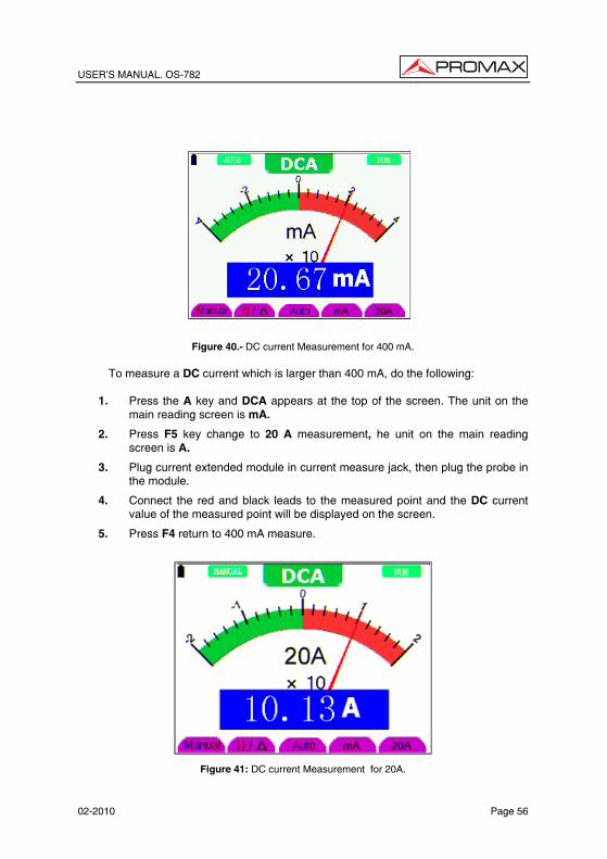
USER’S MANUAL. OS-782
02-2010 Page 56
Figure 40.- DC current Measurement for 400 mA.
To measure a DC current which is larger than 400 mA, do the following:
1. Press the A key and DCA appears at the top of the screen. The unit on the
main reading screen is mA.
2. Press F5 key change to 20 A measurement, he unit on the main reading screen is A.
3. Plug current extended module in current measure jack, then plug the probe in the module.
4. Connect the red and black leads to the measured point and the DC current value of the measured point will be displayed on the screen.
5. Press F4 return to 400 mA measure.
Figure 41: DC current Measurement for 20A.

USER’S MANUAL. OS-782
Page 57 02-2010
Eng
lish
5.4.8 Making an AC Current Measurement
In order to carry out the measurement of current it is necessary to connect in series the meter and the circuit under test. Make sure that the circuit is disconnected before doing this connection.
To measure an AC current which is less than 400 mA, do the following:
1. Press the A key and DCA appears at the top of the screen. The unit on the main reading screen is mA. mA and 20A will display on the right bottom of screen, press F4 or F5 to switch the measurement between Ma and 20A. 400 mA is acquiescently.
2. Press the AUTO SET key once and ACA is visible at the top of the screen.
3. Insert the black lead into the COM banana jack input and the red lead into the mA banana jack input.
4. Connect the red and black leads to the measured point and the AC current value of the measured point will be displayed on the screen. Look at the display; you can see a screen that looks like the following figure 38.
Figure 42.- AC current Measurement for 400 mA.
To measure an AC current which is larger than 400 mA, do the following:
1. Press the AUTO SET key once and ACA is visible at the top of the screen.
2. Press F5 to select 20A measure, the unit of main reading window is A.
3. Press the AUTO SET key once and ACA is visible at the top of the screen.

USER’S MANUAL. OS-782
02-2010 Page 58
4. Plug current extended module in current measure jack, then plug the probe in the module.
5. Connect the red and black leads to the measured point and the AC current value of the measured point will be displayed on the screen.
6. Press F4 return to 400mA measure.
Figure 43.- AC current Measurement for 20A.
5.5 Freezing the Readings.
You can freeze the displayed readings at any time.
1. Press the RUN /STOP key to freeze the screen and STOP will be displayed at the top right of the screen.
2. Again, press the RUN /STOP key, you can resume your measurement.
Look at the display; you can see a screen that looks like the following figure 40.

USER’S MANUAL. OS-782
Page 59 02-2010
Eng
lish
Figure 44: Freezing the Readings.
5.6 Taking a relative measurement
A currently measured result relative to the defined reference value is displayed in a relative measurement.
The following example shows how to take a relative measurement. At first, it is required to acquire a reference value.
1. Press R key and R is displayed on the top side of the screen.
2. Press the AUTO SET key till C appears at the top of the screen.
3. Plug capacitance extended module in capacitance measure jack.
4. When the reading leveling off, press F2 key and is displayed on the
top side of the screen. The saved reference value is displayed below .
5. Plug capacitance, the displayed major reading on the screen is actual the
capacitance value.
Look at the display, you can see a screen that looks like the following figure
32.

USER’S MANUAL. OS-782
02-2010 Page 60
Figure 45.- Relative Measurement.
5.7 Selecting automatic/manual range adjustment
The defaulted range mode of the instrument is automatic range. To switch to the manual range, perform the following steps:
1. Press F1 key and MANUAL is displayed on the top left side of the screen to enter the manual range mode.
2. Under the manual range mode, the measuring range is increased by a stage when pressing F1 key each time, and when reaching the highest stage, it jumps to the lowest stage by pressing F1 key once again. To multiply the reading of dial pointer by multiplying power and the unit of main reading on the screen will get the measurement result.
3. Press F3 key and AUTO is displayed on the top left side of the screen to switch back to the automatic range mode. Look at the display; you can see a screen that looks like the following figure 46.
Figure 46: Automatic/manual range adjustment.
ATTENTION: Capacitance measurement without manual range mode.

USER’S MANUAL. OS-782
Page 61 02-2010
Eng
lish
6 TROUBLE SHOOTING
1. The oscilloscope does not power up.
It may be caused by the dead battery. At this time, the oscilloscope will not start even if it is powered by the battery charger. Firstly, charge the battery and supply the oscilloscope with power through the battery charger. However, don’t switch on the oscilloscope till waiting for 15 minutes. If the oscilloscope still cannot start, please contact PROMAX for service.
2. The oscilloscope stops work only after operating for several seconds.
Probably the battery is dead, Check the battery symbol at the upper right of the
screen. The symbol indicates that the battery has been run out of power and must be charged.
3. The measurement type displays ERR when you switch to the multimeter
mode.
Probably you do not select the measuring mode. In this case, push down any key of the three keys V, A and R. Thus, the relative measuring mode will be shown on the screen. If the ERR is still displayed, restart the oscilloscope.
4. The measured voltage amplitude value is 10 times larger or smaller than
the actual one under the oscilloscope mode.
Check whether the channel attenuation factor matches the actual probe error ratio.
5. The waveform is displayed on the screen but is not stable under the
oscilloscope mode.
• Check whether the signal item in the trigger mode menu matches the actually used signal channel.
• Check on the trigger mode: The edge trigger mode is applicable to the universal single and the video trigger mode applicable to the video signal. Only when the proper trigger mode is applied, can the waveform be in stable.
• Try to change the trigger coupling into the HF repression and LF repression to filter the HF or LF noise trigger by the interference.
USER’S MANUAL. OS-782
02-2010 Page 62
6. There is no display on the screen when you push down RUN/STOP key under the oscilloscope mode.
Check whether the trigger mode in the trigger mode menu is in normal or single shot and whether the trigger level is out of the waveform range.
In such condition, adjust and make the trigger level in the middle or select the non-auto trigger mode. Additionally, press the AUTO SET key and complete the above setting
7. When select the average sampling in the sampling mode or select a longer display time in the display mode under the oscilloscope, the display speed is slow.
It is normal in the above case.
USER’S MANUAL. OS-782
Page 63 02-2010
Eng
lish
7 MAINTENANCE AND CLEANING 7.1 Basic maintenance
Do not store or place the instrument in locations where the liquid crystal display is exposed directly to the light of the sun during long time. Warning: Do not sprinkle the equipment or the probes with liquid or dissolvent agents, to avoid their damage. 7.2 Cleaning
Usually inspect the equipment and the probes, according to the conditions of use. In order to clean the external surface of the instrument, you must follow these instructions:
1. Clean the dust of the external parts of the instrument and the probes with a smooth cloth. When cleaning the liquid crystal display, avoid to damage the protective transparent layer.
2. Only clean the equipment when it is power off, with a previously dampened but not soaked smooth cloth. A light detergent or water can be used. Do not use any abrasive chemical detergent, to avoid damages in the equipment or the probes.
Warning
Before back to power on and to use the instrument, please make sure that it has been completely dried, to avoid short-circuits and personal hazards due to the humidity.
7.3 Storage of oscilloscope
If the equipment is stored during long time, the lithium battery must be recharged before the storage. 7.4 Substitution of the battery of lithium.
Normally it is not necessary to change the battery of lithium. If it was necessary to replace her, only qualified personnel can realize this operation. For more information, put in touch with the PROMAX most nearby office or with his distributor.

USER’S MANUAL. OS-782
02-2010 Page 64