
NMRstabilizationofaHall-controlled electromagnet · changes inthisprobeamiintherestofthecontrol...
8
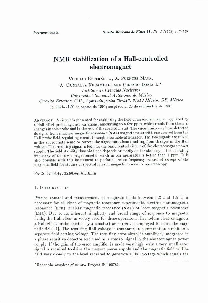
In~trumentación Rev;,ta Mexicana de Fí,ica 38, No. 1 (1992) 142-149 NMR stabilization of a Hall-controlled electromagnet VIRGILIO BELTRÁN L., A. FUENTES MAYA, .A. GONZÁLEZ NUCAMENDI AND GIORGIO LORIA L. * Instituto de Ciencias Nucleares Universidad Nacional Autónoma de México Circuito Exterior, C. U., Apartado postal 70-543, 04510 México, DF, México Recibido el 30 de agoslo de 1991; aceptado el 26 de septiembre de 1991 ABSTRACT. A circuit is presented for stabilizing the field of an electrornagnet rf'glllated by a Hal1-effect probe, against variations, arnounting to a few pprn, which result from thermal changes in this probe ami in the rest of the control circuit. The eircuit rnixes a phase-detected dc signal from a nuclear rnagnelic resonance (NMR) magnetorneter w¡th one derived fram lhe Hall probe field-regulating cireuit lbrough a suitable allenuator. The two signals are mixed in the approprialc sense to corrcct lhe signa] variations resulting from changes in the Hall vollage. The resulling signal is fed into lhe basie eonlrol eireuil of lhe e1eetromagnel power supply. The field slability thus oblained depends prirnarily on tbe stabilily of lhe operating frequeney of the NMRmagnelometer whieh in our apparalus is beller than I ppm. II is also p06siblc with lhis inslrument to perform precise frequency conlrolled sweeps of lhe magnctic ficld for sludies of spec1ral lines in magnelic resonance spectroscopy. PAes: Oi.58.+g; 35.80.+s; 61.16.lIn 1. INTRODUCTION Precise control and measurement of magnetie fields betwccn 0.3 and 1.5 T is neeessary for all kinds of magnetie resonanee experiments, electron paramagnetie resonance (El' R), nuclear magnetie resonance (NMR) or laser rnagnetie reSonance (LMR). Due to its inherent simplicity and broad range of response to magnetie fields, the Hall effeet is widely used for these operations. In modern clectromagnets a Hall-effeet probe excited by a eonstant ae eurrent is employed to sense the mag- netie field [1]. The resulting Hall voltage is compared in a summation cireuit to a separate field setting voltage. The resulting error signal is amplified, integrated in a phase sensitive detector and used as a control signal in the eleetromagnet power supply. Ir the gain of the error amplifier is made very high, only a very small error signal is required to drive lhe magnet power supply and lhe magnetic ficld will be held very closcly to the level required to generate a Hall vollage whieh equals the *Under the auspiecs of DCAPA Projeet IN 100i89.
Transcript of NMRstabilizationofaHall-controlled electromagnet · changes inthisprobeamiintherestofthecontrol...
In~trumentación Rev;,ta Mexicana de Fí,ica 38, No. 1 (1992) 142-149
NMR stabilization of a Hall-controlledelectromagnet
VIRGILIO BELTRÁN L., A. FUENTES MAYA,. A. GONZÁLEZ NUCAMENDI AND GIORGIO LORIA L. *
Instituto de Ciencias NuclearesUniversidad Nacional Autónoma de México
Circuito Exterior, C. U., Apartado postal 70-543, 04510 México, DF, MéxicoRecibido el 30 de agoslo de 1991; aceptado el 26 de septiembre de 1991
ABSTRACT. A circuit is presented for stabilizing the field of an electrornagnet rf'glllated bya Hal1-effect probe, against variations, arnounting to a few pprn, which result from thermalchanges in this probe ami in the rest of the control circuit. The eircuit rnixes a phase-detecteddc signal from a nuclear rnagnelic resonance (NMR) magnetorneter w¡th one derived fram lheHall probe field-regulating cireuit lbrough a suitable allenuator. The two signals are mixedin the approprialc sense to corrcct lhe signa] variations resulting from changes in the Hallvollage. The resulling signal is fed into lhe basie eonlrol eireuil of lhe e1eetromagnel powersupply. The field slability thus oblained depends prirnarily on tbe stabilily of lhe operatingfrequeney of the NMRmagnelometer whieh in our apparalus is beller than I ppm. II isalso p06siblc with lhis inslrument to perform precise frequency conlrolled sweeps of lhemagnctic ficld for sludies of spec1ral lines in magnelic resonance spectroscopy.
PAes: Oi.58.+g; 35.80.+s; 61.16.lIn
1. INTRODUCTION
Precise control and measurement of magnetie fields betwccn 0.3 and 1.5 T isneeessary for all kinds of magnetie resonanee experiments, electron paramagnetieresonance (El' R), nuclear magnetie resonance (NMR) or laser rnagnetie reSonance(LMR). Due to its inherent simplicity and broad range of response to magnetiefields, the Hall effeet is widely used for these operations. In modern clectromagnetsa Hall-effeet probe excited by a eonstant ae eurrent is employed to sense the mag-netie field [1]. The resulting Hall voltage is compared in a summation cireuit to aseparate field setting voltage. The resulting error signal is amplified, integrated ina phase sensitive detector and used as a control signal in the eleetromagnet powersupply. Ir the gain of the error amplifier is made very high, only a very small errorsignal is required to drive lhe magnet power supply and lhe magnetic ficld will beheld very closcly to the level required to generate a Hall vollage whieh equals the
*Under the auspiecs of DCAPA Projeet IN 100i89.
NMR STARILIZATION OF A HALL-CONTROLLED ELECTROMAGNET 143
con,''''' IPc ..••.entR
1.2 ,Hz Hall-.1¡
referenc:e
Elee~'-Supply tomoonetcoils
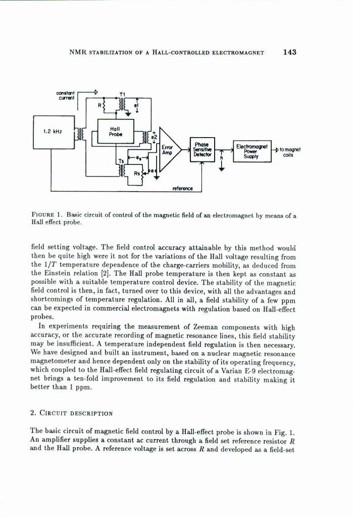
FIGURE 1. Basie eireuit oC control oC the magnetie ¡¡eld oC an eleetromagnet by means oC alIall effeet probe.
field setting voltage. The field control aeeuraey attainable by this method wouldthen be quite high were it not for the variations of the Hall voltage resulting fromthe 1fT temperature dependenee of the eharge-earriers mobility, as dedueed fromthe Einstein relation [2J. The Hall probe temperature is then kept as constant aspossible with a suitable temperature control device. The stability of the magneticfield control is then, in fae!, turned over to this device, with all the advantages andshorteomings of temperature regulation. AIl in all, a field stability of a few ppmcan be expeeted in eommercial eleetromagnets with regulation based on Hall-effeetprobes.In experiments requiring the measurement of Zeeman eomponents with high
aeeuraey, or the aeeurate reeording of magnetie resonanee lines, this field stabilitymay be insullicien!. A temperature independent field regulation is then neeessary.We have designed and built an instrument, based on a nuclear magnetic resonaneemagnetometer and henee dependent only on the stability of its operating frequeney,whieh coupled to the Hall-effee! field regulating cireuit of a Varian £-9 eleetromag-net brings a ten-fold improvement to its field regulation and stability making itbet!er than 1 ppm.
2. CIRCUIT DESCRIPTlON
The basie cireuit of magnetic field control by a Hall-effeet probe is shown in Fig. 1.An amplifier supplies a eonstant ae eurrent through a field set referenee resistor Rand the Hall probe. A referenee voltage is set aeross R and developed as a field-set

144 VIRGlLlO BELTRÁN L. ET AL.
voltage el in the secondary of transformer TI' A field-scan voltage e" developedacross a different transformer T, and a variable resistor R" may be added to el'
The resulting voltage is algebraically added to the transformed Hall voltage e2
and the resulting difference signal e is fed to the error amplifier and its output isphase-detected aud rectified at the phase sensitive detector. The rectified signal his fed as a control signal to the electgromagnet power supply in a negative feedbackconfiguration. Due to the high gain of the error amplifier, only a very small signalis necded to drive the electromagnet power supply. The thermal variations of theHall voltage will then be reproduced as proportional changes in the magnetic field.
A thermal variation in the rectified error signal h can be offEet by adding to it,at the power supply input amplifier, an opposing temperature-independent signalproportional to the change in the magnetic field induced by this variation. One suchsignal can be derived from a first-derivative nuclear magnetic resonance spectralline from a NM R magnetometer locked to the frequency of a precision oscillator(Fig. 2). If a small temperature change occurs in the Hall probe, it will induce aproportional change in the Hall voltage and in the magnetic field. This, in tum, willoffset the NMR magnetometer phase detector from its near-zero value producing adc voltage proportional to the therma! change in the magnetic field. By fecdingthis voltage into the power supply input amplifier in opposition to the originalchange in the magnetic field, this is corrected back towards the value where themagnetometer output nears zero; ¡.e., to the value determined by the rf oscillator.The magnetic field will then be as stable as the frequency from the rf oscillator.With crystal controlled oscillators the stability can be expected to be as high as0.1 ppm although still dependent in temperature in this limit through the crystalthermal properties. If, however, the radio frequency is derived from a es standardthe stability will be higher and truly independent of temperature.
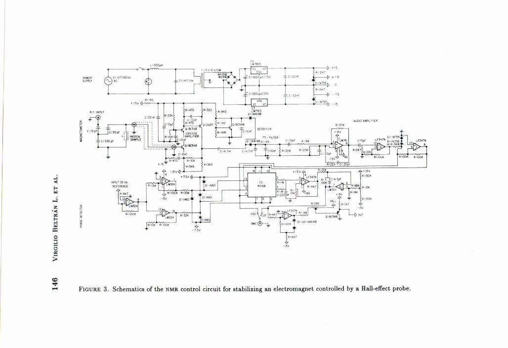
The NMR magnetometer is an improved version of one previously designed andbuilt at our laboratory [3] to which an appropriate phase detector, also of localdesign, has becn added (Fig. 3). A proton-rich liquid sample located inside the coi!of a tank circuit is the magnetic field probe. Electromagnetic power from a precisionradio frequency oscillator, at the resonance frequency f of the tank circuit, is veryloosely coupled to this basic cirenit through a very small capacitor. The magneticfield is sen sed by the power absorption which takes place when the proton Zeemanlevels are exactly a the energy separation !lE = hf required by Planck's law. Thisabsorption is reflected as a change in the rf voltage developed across the tank circuitoBy modulating the magnetic field at a low frequency around the resonance field,35 Hz in our apparatus, the radio frequency signal trasmitted by the tank circuit isamplitude modulated at the same frequency. This signal is amplified and detectedin amplitude and phase by the circuit following the tank circuit [4].
The amplitude-modulated signal is amplified by a cascode rf amplifier followed bya transistor which provides further amplification and a feedback voltage to the firststage of the cascode for stabilizing both its gain and its operating point. The loadof the second stage in the cascode is made dynamically high, and its overall gain

NMR STABILIZATIONOF A IIALL-cONTROLLEDELECTROMAGNET 145
POT PIlosoSensitiveDetector
Eleclrorro¡nelPow.rSupply
JI PIlaso delected-V N.M.R. signal
PIlosoSensitivaDetector
10magnolcoils
MagnetometerPrecisionRFOscillator
FIGURE2. Dasic ci,cuit fo, stabilization of a lIall-effect cont,olled electromagnet by mean.of a NMRsignal.
improved, by means of a bootstrap connection to the emitter of the next transistor.This results in a closed loop gain of about 26 dIl.Detection of the am signal is accomplished in a diode detector in which the
diodes operating point is optimized by polarizing with an active circuit which a!socompensates variations of voltage drop with temperature. A 1rfilter after the diodesattenuales the residual rf to more than 80 dIl.The 35 Hz demodulated audio signal from the detector is amplified by a tuned
active filter of lhe Wien bridge type with a Q of 10. The resulting signal is furtheramplified by 5 and may be observed in an oscilloscope for purposes of tuning theresonant circuitry or to rapidly check for the NMR signal from the magnetometer.The de control signal is obtained by phase detecting the 35 Hz signal from the
audio stage in synchronism with the 35 Hz field modulation. The need for a phaseadjustment, typical of this kind of detectors, is eliminated by deriving the referencesigna! from a resistor connected in series with the field modulation coils. The refer-ence signal is amplified, squared and split into two square waves shifted 1800 withrespect to each other which are, in tum, applied to the control inputs of two lineareMOS gates. A direct and an inverted NMR signa! are fed to the active inputs ofthese gates which work, then, as a full wave synchronous detector in which the deshift of the amplifiers is almost completely cancelled out. After going through twomore stages of low pass filtering and de amplification the signal may be plotted,further amplified or fed to a mixer where it is algebraically added to a signal comingfrom the Hall probe. The mixer oulput is fed to the normal control circuit oC themagnet power supply.
lt'I~O
• !~~
"'"
.,5¥
~UOIO AW9LlroE~
~'2.1-,
0'8C')48
"'~.
O' '02' '''''A8
--i> +I~
~'h722<' l;-----t> .•I~
~<¡, 2.7
22.' f------t> - 1. ~
~~.~-I~
-15V
0'11.60
<.-7.5V
;0"",n.
0"0060
~,n,.;
l'~}OH
e'12.'
. _.. -...-íO'llC~!I ------ .. ~ I, T"1 <,""
prr",~,,; 5"'3.'.•15 "'5~5
,j'L, 'PIlOTO"~ ~ SoIMPLE
11=100.
,""'Uf~H'"ErEIlENa
~"$O""
IU.J ••P\,IT
" +1 ~~ C'I~P~C'50P!
! _"330,'
~~~,
..•""¡-Col
"'"Z
'""'"t;ColelO
~;¡:>
lO••••.... FIGURE 3. Schematics of the NMR control circuit for stabilizing an electromagnet controlled by a lIall.effect probe .
NMR STABILIZATIONOF A IIALL-cONTROLLEOELECTROMAGNET 147
0.4380 T
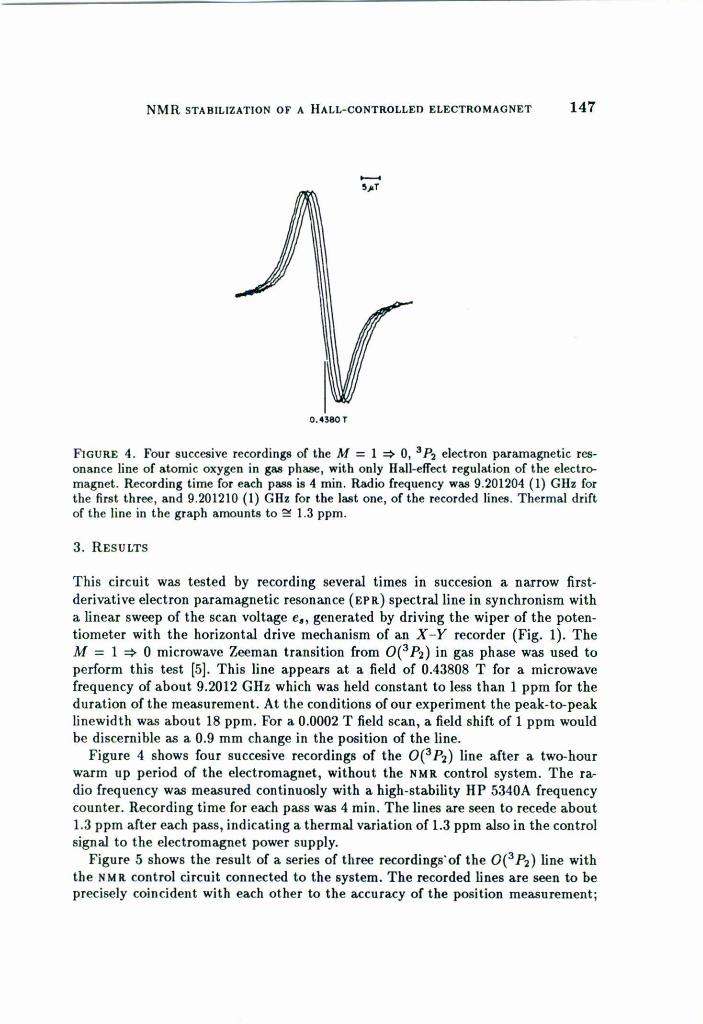
FIGURE 4. Four succesive recordings of the M = 1 ~ O, 3P, electron paramagnetic res-onance line of atomic oxygen in gas phase, with only lIall-effect regulation of the eJectre>-magneto Recording time for each pass is 4 mino Radio frequency was 9.201204 (1) Gllz forthe first three, and 9.201210 (1) Gllz for the last one, of the recorded Iines. Thermal driftof the line in the graph amounts to :!! 1.3 ppm.
3. RESULTS
This circuit was tested by recording several times in succesion a narrow lirst-derivative eleelron paramagnetic resonance (EPR) spectralJine in synchronism witha linear sweep of the sean voltage e•• generated by driving the wiper of the poten-tiometer with the horizontal drive mechanism of an X -y recorder (Fig. 1). TheM = 1 ~ O microwave Zeeman transition from OeP2) in gas phase was used toperform this test [5]. This Jine appears at a lield of 0.43808 T for a microwavefrequency of about 9.2012 GHz which was held constant to less than 1 ppm for theduration of the measurement. At the conditions of our experiment the peak-to-peakJinewidth was about 18 ppm. For a 0.0002 T lield sean, a lield shift of 1 ppm wouldbe discernible as a 0.9 mm change in the position of the Jine.Figure 4 shows four succesive recordings of the OeP2) Jine after a two-hour
warm up period of the electromagnet, without the NMR control system. The ra.dio frequency was measured continuosly with a high-stability HP 5340A frequencycounter. Recording time for each pass was 4 mino The Jines are seen to recede about1.3 ppm after each pass, indicating a thermal variation of 1.3 ppm also in the controlsignal to the electromagnet power supply.Figure 5 shows the result of a series of three recordings'of the OeP2) Jine with
the NMR control circuit connected to the system. The recorded Jines are seen to beprecisely coincident with each other to the accuracy of the position measurement;
148 VIRGILIOBELTRÁNL. ET AL.
0.4380T
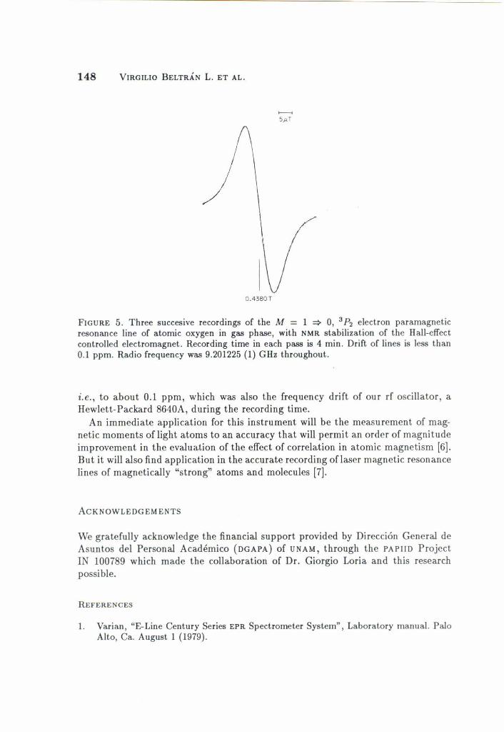
FIGURE 5. Three sueeesive reeordings of the M = 1 ~ O, 3P2 eleetron paramagneticresonanee line of atomic oxygen in gas phase, with NMRstabilization of the lIall.effeeteontrolled eleetromagnet. R.ecording time in eaeh pass is 4 mino Drift of lines is less than0.1 ppm. Radio frequeney was 9.201225 (1) Gllz throughout.
¡.e., to about 0.1 ppm, whieh was also the frequeney drift of our rf oscillator, alIewlett.Paekard 8640A, during the recording time.An immediate applieation for this instrument will be the measurement of mag-
netie moments of Iight atoms to an aeeuraey that will permit an order of magnitudeimprovement in the evalnation of the e!feet of eorrelation in atomie magnetism [6].But it will also find applieation in the aeeurate recording oflaser magnetie resonaneeIines of magnetieally "strong" atoms and moleenles [7).
ACKNOWLEOGEMENTS
\Ve gratefully aeknowledge the financial support provided by Dirección General deAsuntos del Personal Académico (OGAPA) of UNAM, through the PAPIIO ProjeetIN 100789 whieh made the eo\laboration of Dr. Giorgio Loria and this researehpossible.
ItEFERENCES
1. Varian, "E-Line Cenlury Series EPR Spectrometer System", Laboratory manual. PaloAlto, Ca. Augnst 1 (1979).
J'lMR STABILlZATIONOF A HALL-CONTROLLED ELECTROMAGNET 149
2. lIans P.R. Frederikse, In Physics Vademeeum, p. 291. American Institute of Physics,335 East 45th Street, NY (1981).
3. R. Yelarde M. y Y. Beltrán L., Rev. Mer. Fís. 31 (1984) 115.4. E.R. Andrew, in Nuclear Magnetic Resonance, Cambridge University Press (1969),
p.56.5. Y. Beltrán L., J. Rangel G., A. González-Nucamendi, J. Jiménez-Mier and A. Fuentes-
Maya, Phys. Rev. A39 (1989) 58.6. Y. Beltrán L. and J. Jiménez-Mier, Phys. Rev. A43 (1991) 4026.7. R.J. Saykally and K.M. Evenson, J. Chem. Phys. 71(4) (1979) 1564.
RESUMEN. Se presenta un circuito para estabilizar el campo de un electroimán regulado pormedio de una sonda de cfecto Hall, contra variaciones resultantes de cambios térmicos enesta sonda yen el resto del circuito de control. El circuito mezcla la señal de corriente directaproveniente del detector de fase de un magnetómetro de resonancia nuclear magnética(NMR), con la señal de regulación del campo, proveniente de la sonda lIall, convenientementeatenuada y en el sentido apropiado para que se cancelen las variaciones debidas a cambiostérmicos en esta última sonda. La señal resultante se alimenta al circuito básico de controlde la fuente de poder del electroimán. La estabilidad de campo que así se consigue dependeprimordialmente de la estabilidad de la frecuencia de operación del magnetómetro, queen nuestro instrumento es superior a 1 ppm. También es posible con este instrumentohacer barridos precisos del campo magnético controlados por la frecuencia de un oscilador,para hacer estudios de precisión sobre lineas espectrales en espectroscopia de resonanciamagnética.


![Source Controlled Semi-reliable Multimedia Streaming Using …huszak/publ/Source Controlled Semi... · 2007-11-22 · The generally used transport protocols (TCP, UDP) [1,2] were](https://static.fdocuments.ec/doc/165x107/5ec65d2e8fdc5d104a35bab2/source-controlled-semi-reliable-multimedia-streaming-using-huszakpublsource-controlled.jpg)